

Page 1
VS mini J7
Compact General Purpose Inverter
Model: CIMR-J7AZ
200V Class 3-phase 0.1 to 4.0kW
200V Class Single-phase 0.1 to 1.5kW
400V Class 3-phase 0.37 to 4.0kW
QUICK MANUAL
Manual No.
I39E-EN-01
EnglishDeutschEspañolFrançaisItalianoPortuguês
Pyccкий
Page 2

Page 3
General Precautions
z Some drawings in this manual are shown with protective covers or shields removed in
order to show detail with more clarity. Make sure all covers and shields are replaced
before operating the product.
z This manual may be modified when necessary because of improvements to the product,
modifications, or changes in specifications.
z To order a copy of this manual, or if your copy has been damaged or lost , contact your
OMRON YASKAWA Motion Control B. V. (Hereinafter called the OYMC) representatives.
z OYMC is not responsible for any modification of the product made by the user, since that
will void the guarantee.
Safety Information
The following conventions are used to indicate precautions in this document. Failure to heed precautions provided in this document can result in serious or possibly even fatal injury or damage to the
products or to related equipment and systems.
Indicates precautions that, if not heeded,
WARNING
CAUTION
could possibly result in loss of life or serious injury.
Indicates precautions that, if not heeded,
could result in relatively serious or minor injury,
damage to the product, or faulty operation.
Failure to heed a precaution classified as a caution can result in serious consequences depending on
the situation.
Precautions for UL/cUL Marking
· Do not connect or disconnect wiring, or perform signal checks while the power supply is turned ON.
· The Inverter internal capacitor is still charged even after the power supply is turned OFF. To prevent
electric shock, disconnect all power before servicing the Inverter, and then wait at least one minute
after the power supply is disconnected. Confirm that all indicators are OFF before proceeding.
· Do not perform a withstand voltage test on any part of the Inverter. The Inverter is an electronic
device that uses semiconductors, and is thus vulnerable to high voltage.
· Do not remove the Digital Operator or the blank cover unless the power supply is turned OFF.
Never touch the printed circuit board (PCB) while the power supply is turned ON.
· This Inverter is not suitable for use on a circuit capable of delivering more than 18,000RMS
symmetrical amperes, 250 volts maximum (200V class Inverters) or 480 volts maximum (400 V class
Inverters).
CAUTION
Use 75 °C copper wires or equivalent.
Low voltage wires shall be wired with Class I Wiring.
Page 4
Precautions for CE Markings
· Only basic insulation to meet the requirements of protection class I and overvoltage category II is
provided with control circuit terminals.
Additional insulation may be necessary in the end product to conform to CE requirements.
· For 400 V class Inverters, make sure to ground the supply neutral to conform to CE requirements.
· For conformance to EMC directives, refer to section 3 in this document.
For details, refer to the following document.
Document No. EZZ008390 for English version.
· Our products are tested by authorized bodies using the standards listed below.
Product standard: EN61800-3 : 1996
EN61800-3 ; A11 : 2000
Receiving
CAUTION
Do not install or operate any Inverter that is damaged or has missing parts.
Failure to observe this caution may result in injury or equipment damage.
· Verify that the part numbers match your purchase order or packing slip.
· Check the unit for physical damage that may have occurred during shipping.
Page 5
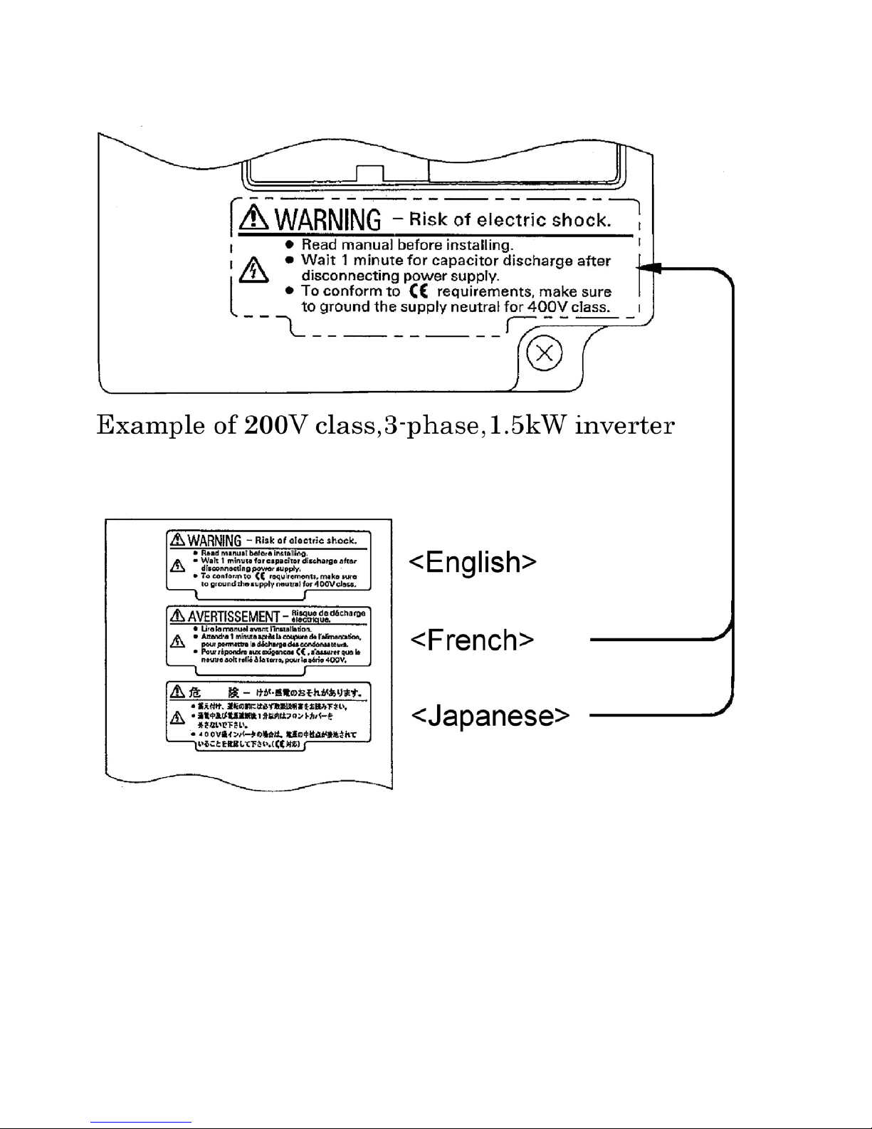
Warning Display
Japanese/French Warning Display
An English warning display is on the front panel of the inverter.
If you need Japanese or French warning display, use the stickers at the back of this manual.
Place it over the English warning display.
Page 6
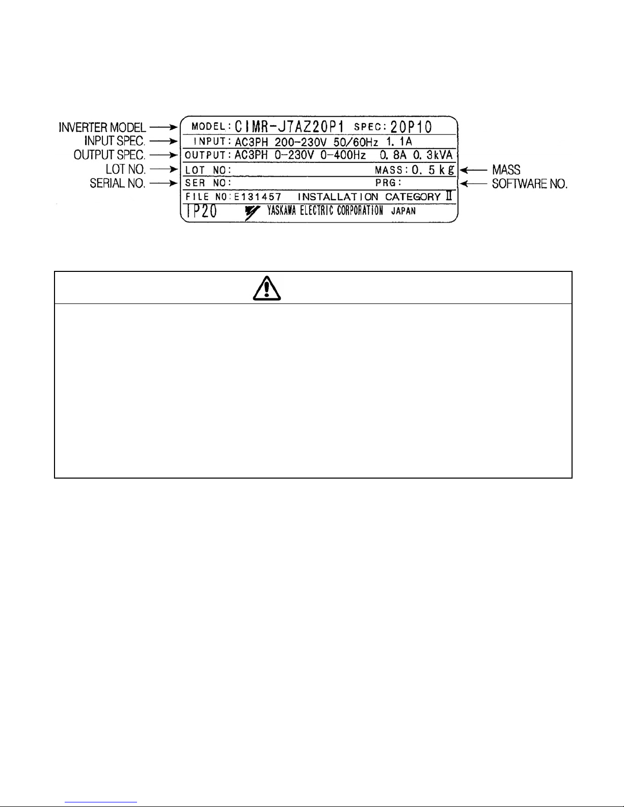
Checking the Name Plate
Example of 3-phase, 200VAC, 0.1kW (0.13HP)
Mounting
CAUTION
· Lift the cabinet by the heatsink. When moving the Inverter,
never lift it by the plastic case or the terminal covers.
Otherwise, the main unit may fall and be damaged.
· Mount the Inverter on nonflammable material (i.e., metal).
Failure to observe this caution may result in a fire.
· When mounting Inverters in an enclosure, install a fan or other cooling
device to keep the intake air temperature below 122°F (50°C)
for IP20 (open chassis type), or below 105°F(40°C) for NEMA1 (TYPE1).
Overheating may cause a fire or damage the Inverter.
· The VS mini generates heat. For effective cooling, mount it vertically.
Refer to the figure in Mounting Dimensions on section 3.
Page 7
Wiring
WARNING
· Only begin wiring after verifying that the power supply is turned OFF.
Failure to observe this warning may result in an electric shock or a fire.
· Wiring should be performed only by qualified personnel.
Failure to observe this warning may result in an electric shock or a fire.
· When wiring the emergency stop circuit, check the wiring thoroughly before operation.
Failure to observe this warning may result in injury.
· Always ground the ground terminal according to the local grounding code.
Failure to observe this warning may result in an electric shock or a fire.
· For 400V class, make sure to ground the supply neutral.
Failure to observe this warning may result in an electric shock or a fire.
· If the power supply is turned ON during the FWD(or REV) RUN command is given,
the motor will start automatically.
Turn the power supply ON after verifying that the RUN signal is OFF.
Failure to observe this warning may result in injury.
· When the 3-wire sequence is set, do not make the wiring unless the multi-function input
terminal parameter is set.
Failure to observe this warning may result in injury.
CAUTION
· Verify that the Inverter rated voltage coincides with the AC power supply voltage.
Failure to observe this caution may result in personal injury or a fire.
· Do not perform a withstand voltage test on the Inverter.
Performing withstand voltage tests may damage semiconductor elements.
· To connect a Braking Resistor, Braking Resistor Unit, or Braking Unit, follow the
Procedure described in this manual.
Improper connection may cause a fire.
· Always tighten terminal screws of the main circuit and the control circuits.
Failure to observe this caution may result in a malfunction, damage or a fire.
· Never connect the AC main circuit power supply to output terminals U/T1, V/T2 or W/T3.
The Inverter will be damaged and the guarantee will be voided.
· Do not connect or disconnect wires or connectors while power is applied to the circuits.
Failure to observe this caution may result in injury.
· Do not perform signal checks during operation.
The machine or the Inverter may be damaged.
Page 8
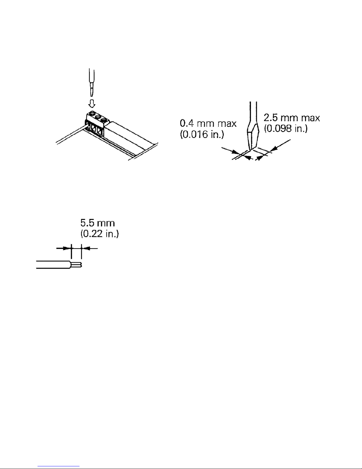
Preautions for wiring
Wiring the control circuit terminals Screwdriver blade width
Insert the wire into the lower part of the terminal block
and connect it tightly with a screwdriver.
Wire sheath strip length must be 5.5mm (0.22in).
Page 9

Operation
WARNING
· Only turn ON the input power supply after confirming the Digital Operator
or blank cover(optional) are in place. Do not remove the Digital Operator or
the covers while current is flowing.
Failure to observe this warning may result in an electric shock.
· Never operate the Digital Operator or DIP the switches with wet hands.
Failure to observe this warning may result in an electric shock.
· Never touch the terminals while current is flowing, even if the Inverter is stopping.
Failure to observe this warning may result in an electric shock.
· When the fault retry function is selected, stand clear of the Inverter or the load.
The Inverter may restart suddenly after stopping.
(Construct the system to ensure safety, even if the Inverter should restart.)
Failure to observe this warning may result in injury.
· When continuous operation after power recovery is selected, stand clear of the
Inverter or the load. The Inverter may restart suddenly after stopping.
(Construct the system to ensure safety, even if the Inverter should restart.)
Failure to observe this warning may result in injury.
· The Digital Operator stop button can be disabled by a setting in the Inverter.
Install a separate emergency stop switch.
Failure to observe this warning may result in injury.
Page 10
WARNING
· If an alarm is reset with the operation signal ON, the Inverter will restart automatically.
Reset an alarm only after verifying that the operation signal is OFF.
Failure to observe this warning may result in injury.
· When the 3-wire sequence is set, do not make the wiring unless the multi-function input
terminal parameter is set.
Failure to observe this warning may result in injury.
CAUTION
· Never touch the heatsinks, which can be extremely hot.
Failure to observe this caution may result in harmful burns to the body.
· It is easy to change operation speed from low to high. Verify the safe working
range of the motor and machine before operation.
Failure to observe this caution may result in injury and machine damage.
· Install a holding brake separately if necessary.
Failure to observe this caution may result in injury.
· If using an Inverter with an elevator, take safety measures on the elevator
to prevent the elevator from dropping.
Failure to observe this caution may result in injury.
· Do not perform signal checks during operation.
The machine or the Inverter may be damaged.
· All the constants set in the Inverter have been preset at the factory.
Do not change the settings unnecessarily.
The Inverter may be damaged.
Page 11
Maintenance and Inspection
WARNING
· Never touch high-voltage terminals on the Inverter.
Failure to observe this warning may result in an electrical shock.
· Disconnect all power before performing maintenance or inspection, and then wait at
least one minute after the power supply is disconnected. Confirm that all indicators are
OFF before proceeding.
If the indicators are not OFF, the capacitors are still charged and can be dangerous.
· Do not perform withstand voltage test on any part of the VS mini.
The Inverter is an electronic device that uses semiconductors, and is thus vulnerable to
high voltage.
· Only authorized personnel should be permitted to perform maintenance, inspections, or
parts replacement.
(Remove all metal objects (watches, bracelets, etc.) before starting work.)
Failure to observe these warnings may result in an electric shock.
CAUTION
· The control PCB board employs CMOS ICs. Do not touch the CMOS elements.
They are easily damaged by static electricity.
· Do not connect or disconnect wires, connectors, or the cooling fan while
power is applied to the circuit.
Failure to observe this caution may result in injury.
Page 12
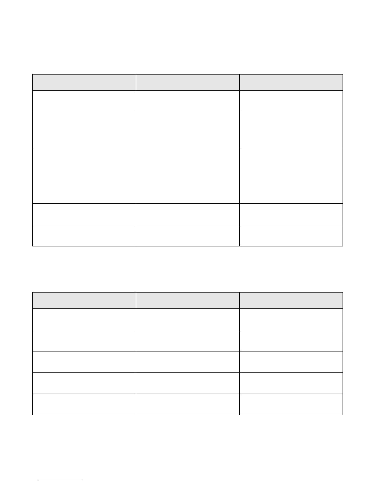
Periodical Inspection
Periodically inspect the inverter as described the following table to prevent accidents and to ensure
high performance with high-reliability.
Location to check Check for Solution
Terminals, unit mounting screws,
etc.
Connection hardware is properly
seated and securely tightened.
Properly seat and tighten
hardware.
Blow with dry compressed air:
Heatsink Built up durst, and debris
39.2 x 10
57 to 85 psi (4 to 6kg / cm
pressure.
Blow with dry compressed air:
39.2 x 10⁴ to 58.8 x 10⁴ Pa,
Printed circuit board
Accumulation of conductive
material or oil mist
57 to 85 psi (4 to 6kg / cm
pressure
If dust or oil cannot be removed,
replace the inverter unit.
Power elements and
smoothing capacitor
Abnormal odor or discoloration Replace the inverter unit.
Abnormal noise or vibration
Cooling fan
Cumulative operation time
Replace the cooling fan.
Part Replacement
Inverter’s maintenance periods are noted below. Keep them as reference.
4
to 58.8 x 10⁴ Pa,
2
)
2
)
Part Replacement Guidelines
Part Standard Replacement Period Replacement Method
Cooling fan 2 to 3 years Replace with new part.
Smoothing capacitor 5 years
Replace with new part.
(Determine need by inspection.)
Breaker relays – Determine need by inspection.
Fuses 10 years Replace with new part.
Aluminium capacitors on PCBs 5 years
Replace with new part.
(Determine need by inspection.)
Note: Usage conditions are as follows:
· Ambient temperature: Yearly average of 30°C
· Load factor: 80% max.
· Operating rate: 12 hours max. per day
Page 13
Others
WARNING
· Never modify the product.
Failure to observe this warning can result in an electric shock or injury
and will invalidate the guarantee.
CAUTION
· Do not subject the Inverter to halogen gases, such as fluorine, chlorine, bromine,
and iodine, at any time even during transportation or installation.
Otherwise, the Inverter can be damaged or interior parts burnt.
Page 14

Page 15

VS MINI J7
Quick Start Guide
1. Wiring
2. Control Circuit Terminals
ENGLISH
3. Installation
4. Start up and Trial run
5. Quick Parameter List
6. Monitors
7. Faults and Alarms
Page 16
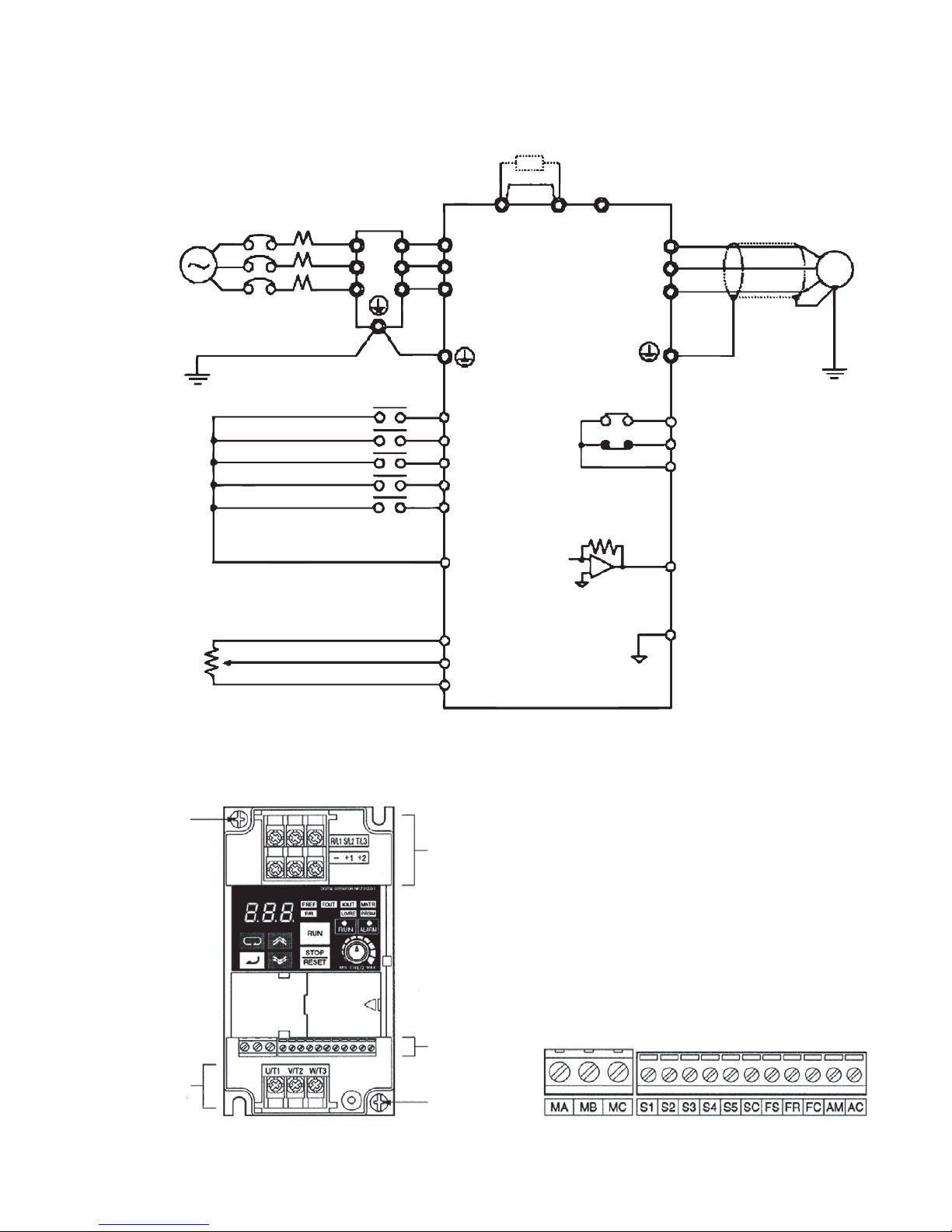
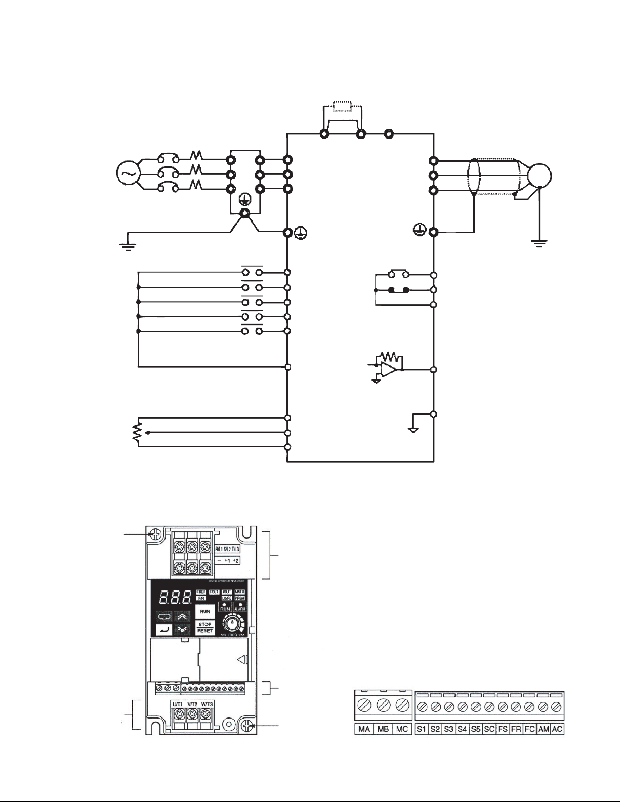
1. Wiring
3-phase 200 V AC
single-phase 200 V AC
(see note 1)
External frequency
adjuster
(2 kΩ 1/4 W min.)
3G3JV PFI @
Noise Filter
L1
L2
L3
Forward/Stop
Multi-function input 1 (S2)
Multi-function input 2 (S3)
Multi-function input 3 (S4)
Multi-function input 4 (S5)
Sequence input common
Frequency reference power
supply 20mA at +12V
Frequency reference input
Frequency reference common
L1i
L2i
L3i
+1 +2 -
R/L1
S/L2
T/L3
S1
S2
S3
S4
S5
SC
FS
FR
FC
SHORT BAR
U/T1
V/T2
W/T3
Multi-function contact output
MA
NO
MB
NC
MC
Common
AM
Analog monitor output
AC
Analogue monitor output
common
M
Note 1: Connect single-phase 200 V AC to terminals R/L1 and S/L2 of the J7AZB
Note 2: The braking resistor cannot be connected because no braking transistor is incorporated.
Ground terminal
Main circuit input
terminals
Arrangement of Control Circuit Terminals
Main circuit
output terminals
Control circuit
terminals
Ground
terminal
Page 17
2. Control Circuit Terminals
Symbol Name Function Signal Level
Input S1 Forward/Stop Forward at ON/Stops at OFF Photocoupler 8 mA
S2 Multi-function Input 1 Set by parameter n36 (Reverse/Stop)
*2
S3 Multi-function Input 2 Set by parameter n37 (External Fault: NO)
S4 Multi-function Input 3 Set by parameter n38 (Fault Reset)
S5 Multi-function Input 4 Set by parameter n39
(Multi-step reference 1)
*2
*2
at 24 V DC
*2
SC Sequence Input Common Common for S1 through S5
FS Frequency Reference Power Supply DC power supply for frequency reference use 20 mA at 12 V DC
FR Frequency Reference Input Input terminal for frequency reference use 0 to 10 V DC (20 kΩ)
FC Frequency Reference Common Common for frequency reference use 4 to 20 mA
0 to 20 mA
Output MA MBMulti-function output: NO
Multi-function output: NC
MC Multi-function output Common Common for MA and MB use
AM Analogue Monitor output Set by parameter n44 (Output frequency)
AC Analogue Monitor output Common Common for AM use
Set by parameter n40 (during running)
*2
Relay output 1 A
max. at 30 V DC and
250 V AC
*2
12 mA max. at 0 to
10 V DC
*1 NPN is the setting for these terminals. No external power supply is required. Refer to connections shown below
*2 Functions in parentheses are default settings.
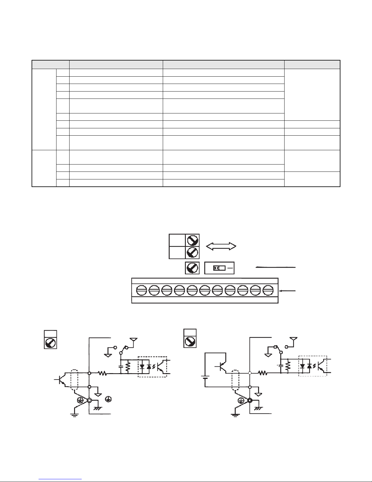
Selecting Input Method
PNP
NPN
SW7
SW7
V
SW8
I
OFF
SW8
Switches SW7and SW8, both of
which are located above the control circuit terminals, are used for input method selection.
Remove the front cover and optional cover to use these switches.
*1
Control circuit
terminal block
Selecting Sequence Input Method
By using SW7, NPN or PNP input can be selected as shown below
NPN
(Default setting)
S1 to 5
SC
GND
3.3k
0.1µ
GND
SW7
24V
360
PNP
24 V DC
(±10%)
S1 to 5
SC
GND
3.3k
0.1µ
GND
SW7
Control circuit
terminal block
24V
360
Page 18
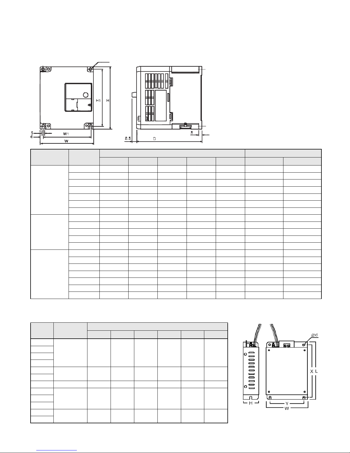
3. Installation
Two 5 dia holes
Rated
Volta ge
Three Phase
200 V AC
Single Phase
200 V AC
Three Phase
400 V AC
Model
J7AZ
20P1 68 128 70 56 118 5 2
20P2 68 128 70 56 118 5 2
20P4 68 128 102 56 118 5 2
20P7 68 128 122 56 118 10 2
21P5 108 128 129 96 118 20 2
22P2 108 128 154 96 118 20 3.5
24P0 140 128 161 128 118 30 5.5
B0P1 68 128 70 56 118 5 2
B0P2 68 128 70 56 118 5 2
B0P4 68 128 112 56 118 10 2
B0P7 108 128 129 96 118 20 3.5
B1P5 108 128 154 96 118 20 5.5
40P2 108 128 81 96 118 5 2
40P4 108 128 99 96 118 5 2
40P7 108 128 129 96 118 5 2
41P5 108 128 154 96 118 10 2
42P2 108 128 154 96 118 10 2
43P0 140 128 161 128 118 20 2
44P0 140 128 161 128 118 20 2
Dimensions (mm) Supply Recommendations
W H D W1 H1 MCCB (A) Wire (mm²)
Noise Filter Specifications
Model
J7AZ
20P1 PFI2010-SE 82 194 50 92 181 5.3
20P2
20P4
20P7
21P5 PFI2020-SE 111 169 50 91 156 5.3
22P2
24P0 PFI2030-SE 144 174 50 120 161 5.3
B0P1 PFI1010-SE 71 169 45 51 156 5.3
B0P2
B0P4
B0P7 PFI1020-SE 111 169 50 91 156 5.3
B1P5
Filter
3G3JV-
Dimensions
W L H Y X d
Page 19

Model
J7AZ
Filter
3G3JV-
Dimensions
W L H Y X d
40P2 PFI3005-SE 111 169 50 91 156 5.3
40P4
40P7 PFI3010-SE 111 169 50 91 156 5.3
41P5
42P2
43P0 PFI3020-SE 144 174 50 120 161 5.3
44P0
Installation of noise filter and J7
Shield
Cable
Control Panel Control Panel
Schaffner
RFI Filter
3 Phase
Metal Mounting
Plate
Ground
Bonds
(remove
any paint)
Schaffner
RFI Filter
3 Phase
J7Series
Inverter
Ground Bonds
(remove any paint)
Shield
Cable
Max. 20m
Motor Cable
Ground Bonds
(remove any paint)
J7Series
Inverter
Shield
Cable
Metal Mounting
Plate
Ground
Bonds
(remove
any paint)
Shield
Cable
Max. 20m
Motor Cable
CIMR-J7@@@@20P1 to 24P0 CIMR-J7@@@@B0P1 to B4P0
CIMR-J7@@@@40P2 to 44P0
Page 20
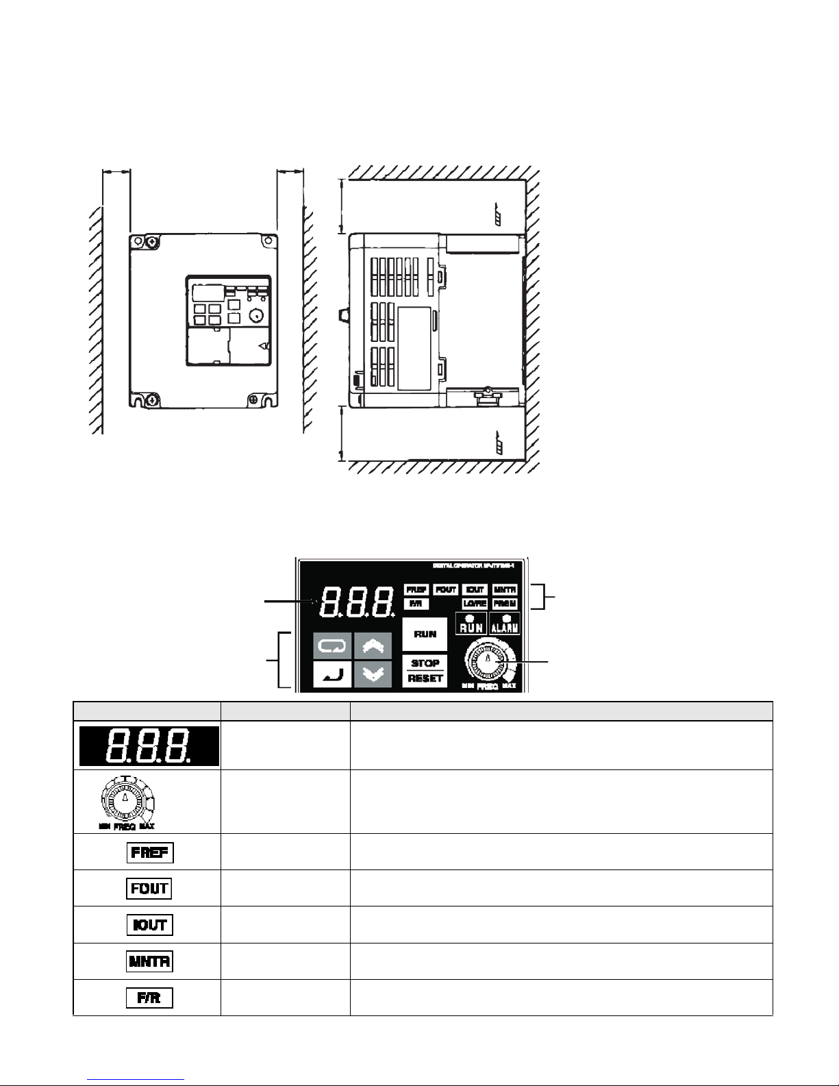
Mounting Dimensions
30mm
(1.18 in.)
OR MORE
30mm
(1.18 in.)
OR MORE
OR MORE
100mm (3.94 in.)
OR MORE
100mm (3.94 in.)
4. Start up and Trial run
AIR
AIR
Data display
Keys
Appearance Name Function
Data display Displays relevant data items, such as frequency reference,
output frequency and parameter set values.
FREQ adjuster Sets the frequency reference within a range between OHz
and the maximum frequency.
FREF indicator The frequency reference can b& monitored or set while
this indicator is lit.
FOUT indicator The output frequency of the Inverter can be monitored
or set while this indicator is lit.
IOUT indicator The output current of the inverter this indicator is lit.
MNTR indicator The values set in U01 through U10 are monitored
while this indicator is lit.
F/R idicator The direction of rotation can be selected while this indicator
is lit when operating the Inverter with the RUN Key.
Indicators
(Setting/Monitor
item indicators)
FREQ adjuster
Page 21
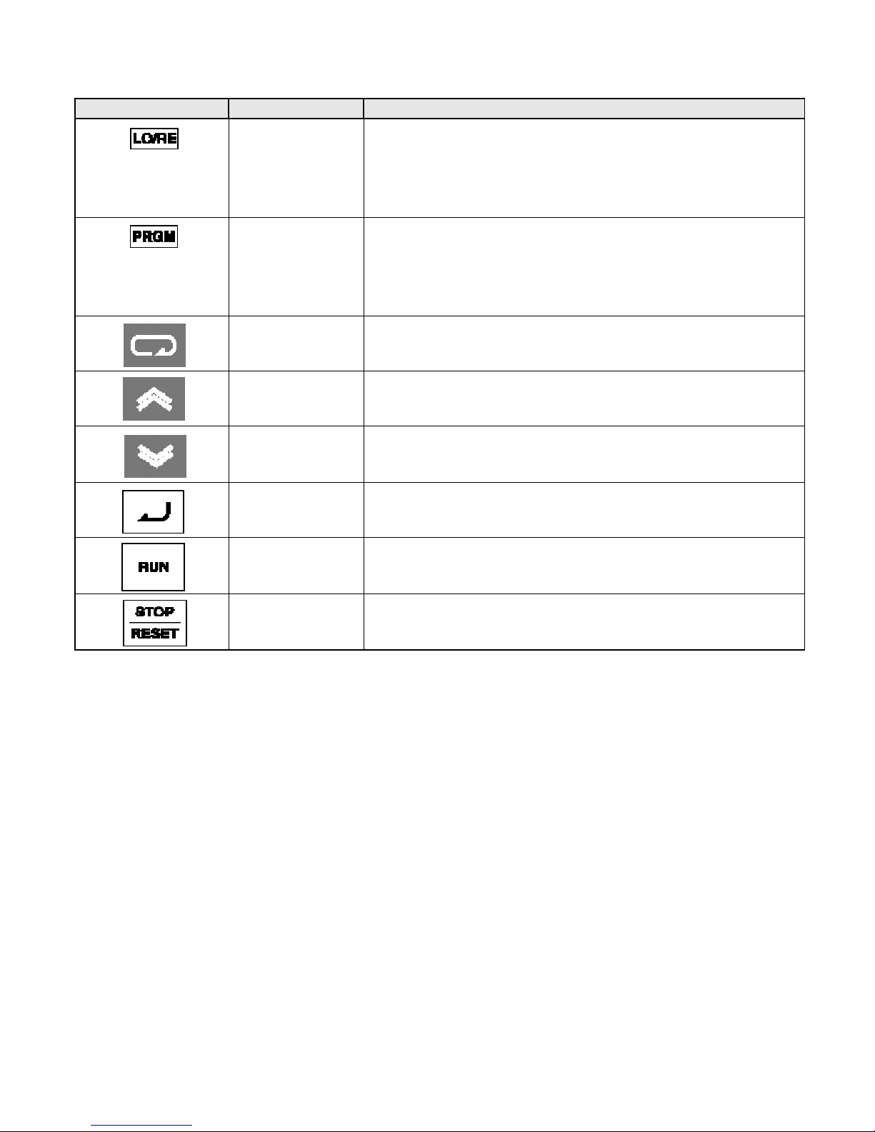
Appearance Name Function
LO/RE indicator The operation of the Inverter through the Digital Operator or
according to the sot parameteres is selectable while this
indicator is lit.
Note: The status of this indicator can be only monitored
while the Inverter is in operation. Any RUN command
input is ignored while this indicator is lit.
PRGM indicator The parameter in n01 through to n79 can be set or monitored while this
indicator is lit.
Note:
While the Inverter is in operation, the paramete can be
only monitored and only some parameti can be
changed. Any RUN command input is ignored while
this indicator is lit.
Mode Key Switches the setting and monitor item indicators in sequence.
Parameter being set will be cancelled if this key is pressed
before entering the setting.
Increment Key Increases multi-function monitor numbers, parameter
num-bers and parameter set values.
Decrement Key Decreases multi-function monitor numbers, parametei
numbers and parameter sel values.
Enter Key Enters multi-function monitor numbers, parameter numl and
internal data values after they are set or changed.
RUN Key Starts the Inverter running when the 3G3JV is in operation
with the Digital Operator.
STP/RESET Key Stops the Inverter unless parameter nO6 is not set to
disable the STOP Key.
The following seven steps describe the recommended minimum operations
to allow the J7 to control a connected motor in typical configuration, to allow
simple operation in the quickest time:
Step 1 – initial checks
1-1 Checkpoints before connecting the power supply.
Check that the power supply is as of the correct voltage.
CIMR-J7AZ2@@@: Three phase 200 to 230VAC
CIMR-J7AZB@@@: Single phase 200 to 240VAC (Wire R/L1 and S/L2)
CIMR-J7AZ4@@@: Three phase 380 to 460VAC
1-2 Make sure that the motor output terminals (U/T1, V/T2, W/T3) are connected to the motor.
1-3 Ensure that the control circuit terminals and the control device are wired correctly.
1-4 Make sure that all control terminals are turned off.
1-5 Set the motor to no-load status (i.e. not connected to the mechanical system)
Step 2 – Connecting the power supply and check the display status
2-1 After conducting the checks in step-1, connect the power supply.
2-2 If the display is normal when the power is connected it will read as follows;
Page 22
RUN indicator: flashes
ALARM indicator: off
Setting/monitor indicators: FREF, FOUT or IOUT is lit.
Data display: displays the corresponding data for the indicator that is lit.
When fault has occurred, the details of the fault will be displayed. In that case, refer to user’s
manual and take necessary action.
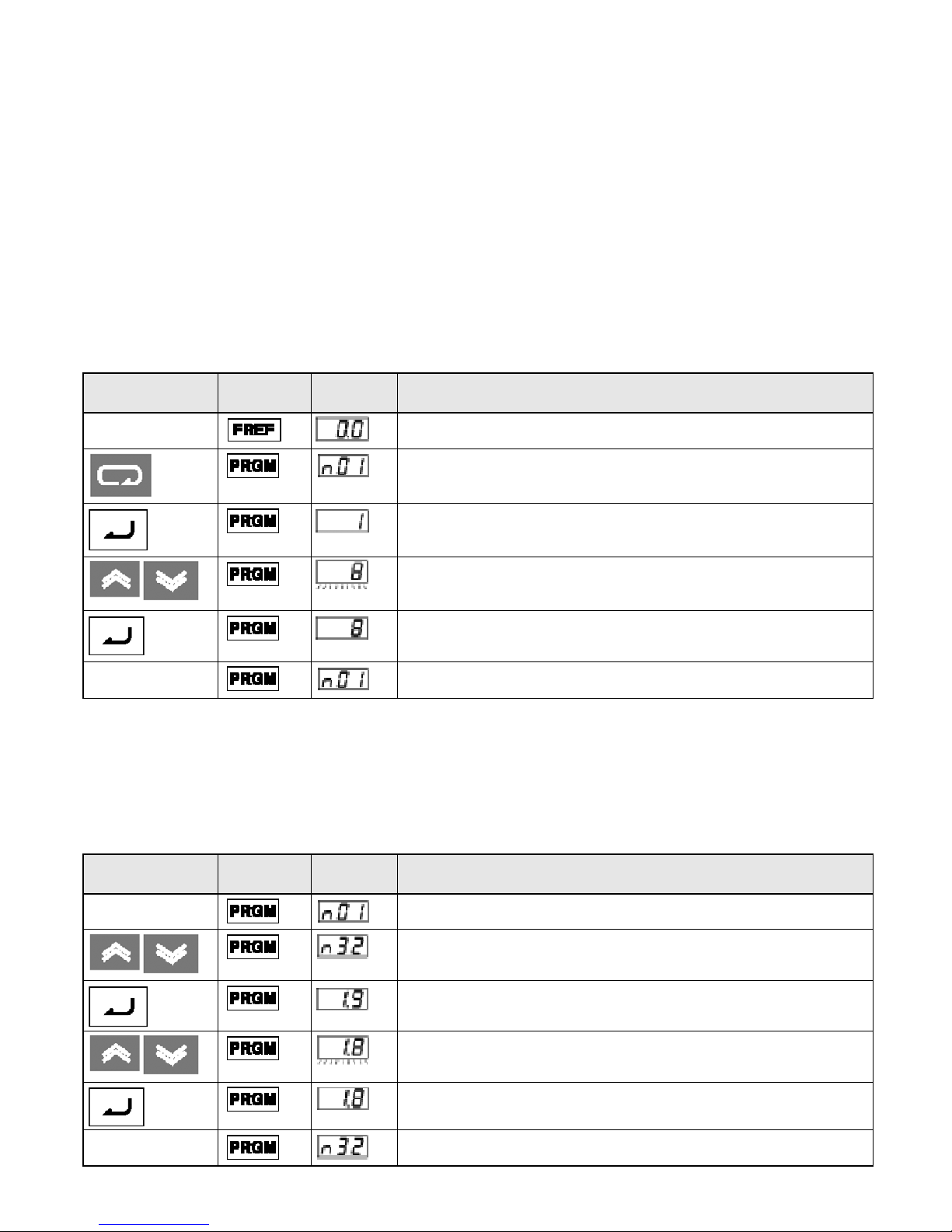
Step 3 – Initializing parameters
To initialize the drive parameters to factory defaults, set parameter n01 = 8. This will set the J7 to
accept start/stop commands in what in termed “2-wire control”, i.e. 1 wire for a motor forward/stop
command, and 1 wire for a motor reverse/stop command.
Key
Sequence
In approximately
1s.
Indicator
Display
example
Explanation
Power On
Press the Mode Key repeatedly until the PRGM indicator is lit.
Press the Enter Key. The data of n01 will be displayed.
Use the Increment or Decrement Key to set n01 to 8. The display will
flash.
Press the Enter Key so that the set value will be entered and the data
display will be lit.
The parameter number will be displayed.
Step 4 – Set the motor rated current
This parameter is used for the electronic thermal function for motor overload detection (OL1). By correctly setting this, the J7 will protect an overloaded motor from burning out.
Read the rated current (in amps) on the motor nameplate, and enter this into parameter n32. The
example to the below shows entering a value of 1.8Amps.
Key
Sequence
In approximately1s. The parameter number will be displayed.
Indicator
Display
example
Explanation
Displays the parameter number
Use the Increment or Decrement Key until n32 is displayed.
Press the Enter Key. The data of n32 will be displayed.
Use the Increment or Decrement Key to set the rated motor current. The
display will flash.
Press the Enter Key so that the set value will be entered and the data
display will be lit.
Page 23

Step 5 – Set the motor rated frequency
This is the maximum frequency the motor can run and allows the J7 to properly control the motor.
Read the rated frequency (in Hz) on the motor nameplate, and enter this into parameters n09 and n11
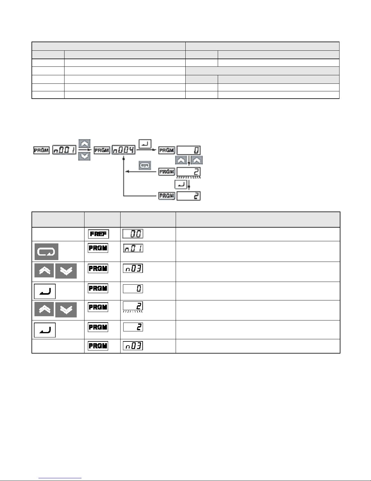
Step 6 – Set the operation command
This is the method for motor run and stop commands (i.e. how the inverter will start and stop the
motor). The two basic operations are for the RUN and STOP/RESET keys on the Digital Operator, or
for one of multi-function inputs through the control circuit terminals.
To set the operation command, enter the appropriate value into parameter n02:
0 = RUN and STOP/RESET keys on the Digital Operator are enabled.
1 = Multi-function inputs through the control circuit terminals.
The diagram to the below shows how to connect a switch to start/stop the motor in the forward direction in “2-wire control”. Set parameter n02=1. To enable a separate switch for reverse rotation on control terminal S2, set parameter n36=2 (this is actually the factory default setting for n36).
FWD RUN/STOP
REV RUN/STOP
.
Step 7 – Set the frequency reference
This is the method for selecting the source for the motor speed command. The factory default is for the
potentiometer on the digital Operator (FREF adjuster), in which case no setting is required.
Frequency reference can also come from an external potentiometer, an analog output from a PLC, or
up to 8 pre-programmed speeds held in the inverter and selected via the multi-function inputs.
For example, to accept frequency reference from an external potentiometer, or a 0-10V analog out
from a PLC, set parameter n03=2.
FS
( )
FREQUENCY
SETTING
MASTER SPEED
FREQUENCY
REFERENCE
(0 TO +10V)
POWER
+12V, 20mA
FR
FC(0V)
Page 24
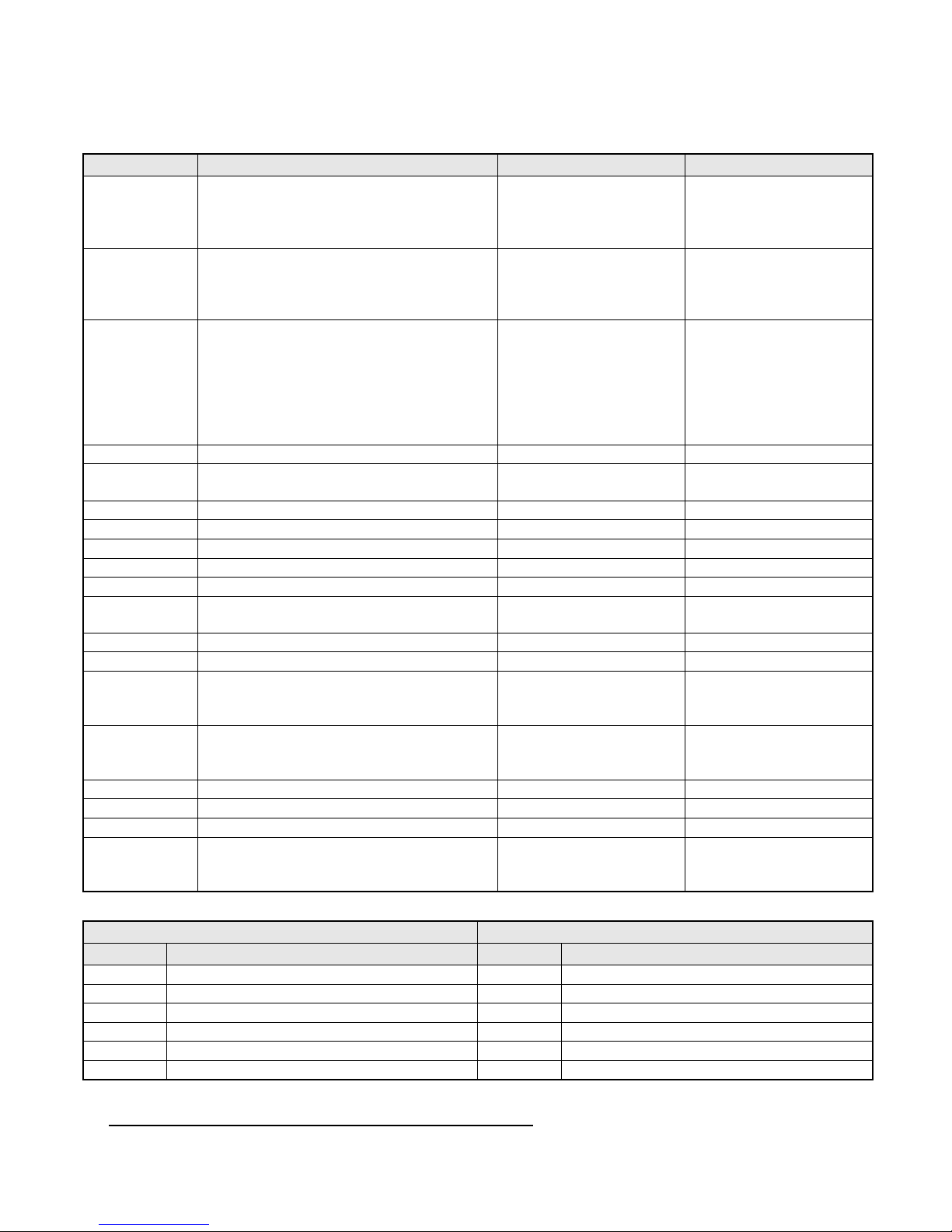
5. Quick Parameter List
*1
Parameter No. Description Range Default
n01 Parameter access:
0: Limited parameter access
1: Full parameter access
8: Factory parameter initialise
n02 Run command selection:
0: Digital operator
1: Control circuit terminal
2: Communication (option)
n03 Frequency reference selection:
0: Digital operator (potentiometer)
1: Frequency reference 1 (n21)
2: Control circuit terminal (0 to 10V)
3: Control circuit terminal (4 to 20mA)
4: Control circuit terminal (0 to 20mA)
6: Communication (option)
n09 Maximum output frequency 50 to 400Hz
n10 Maximum output voltage 1 to 255V (200V class)
N11 Maximum voltage output frequency 50 to 400Hz
n16 Acceleration time 1 0.0 to 999sec 10sec
n17 Deceleration time 2 0.0 to 999sec 10sec
n21 Frequency reference 1 0.0 to 400Hz 50Hz
n22 - n28 Frequency reference 2 - 8 0.0 to 400Hz 0Hz
n32 Motor rated current Depending on model 0 to 120% of inverter rated
n36 - n39 Multi-function input (S2 -S5) 0 to 35 -n40 Multi-function output (MA-MB-MC) 0 to 18 1
n44 Multi-function analog output (AM-AC):
0: Output frequency (10V/Max, freq.)
1: Output current (10V/Inverter rated current)
n46 Carrier frequency 1 to 4 (2.5 - 10kHz)
n52 DC injection braking current 0 to 100% 50%
n53 DC injection braking at stop 0 to 100% 50%
n54 DC injection braking at start 0 to 100% 50%
n55 Stall prevention during deceleration:
0: Enabled
1: Disabled
0 to 9 1
0 to 2 0
0 to 4, 6 0
200 (200V class)
1 to 510V (400V class)
0,1 0
7 to 9 (Proportional to
output freq.)
0,1 0
400 (400V class)
output current
Depending on model
Multi-function Inputs Multi-function Outputs
*1
Value
2 Reverse/Stop 0 Fault Output
3 External Fault (NO) 1 During Run
4 External Fault (NC) 2 Frequency agree
5 Faul reset 6 Overtorque being monitored (NO)
6 Multi-step speed reference 1 12 RUN mode
7 Multi-step speed reference 2 13 Inverter ready
Function Value
*1 Refer to user’s manual for complete list
*1
Function
Page 25
Multi-function Inputs Multi-function Outputs
*1
Value
8 Multi-step speed reference 3 15 Undervoltage in progress
10 Inching Command
12 External base block (NO)
13 External Base block (NC) 0 Otput frequency
17 Local/Remote selection 1 Output current
*1 Refer to user’s manual for full set value
Function Value
*1
Function
Analogue Output Functionsts
*1
Value
Function
Example of Parameter Settings
Cancels
Set Data
In approximately 1s.
Key
Sequence
In approximately
1s.
Indicator Display example Explanation
Power On
Press the Mode Key repeatedly until the PRGM indicator
is lit.
Use the Increment or Decrement Key to set the parameter
number.
Press the Enter Key. The data of the selected parameter
number will be displayed.
Use the Increment or Decrement Key to set the data.
At that time, the display will flash.
Press the Enter Key so that the set value will be entered and the
data display will be lit (see note 1)
The parameter number will be displayed.
Note 1: To cancel the set value, press the Mode Key instead, The parameter number will be
displayed.
2: There are parameters that cannot be changed while the Inverter is in operation. Refer to the
list of parameters. When attempting to change such parameters, the data display will not
change by pressing the Increment or Decrement Key.
Page 26
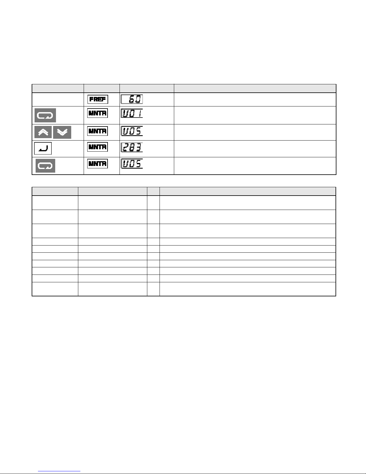
6. Monitors
The Vs mini J7 allows you to monitor various conditions, such as output current and status of multifunction inputs.
This monitoring is performed via the “U” parameters.
Key Secuence Indicator Display example Explanation
Power On
Press the Mode Key repeatedly until the MNTR indicator
is lit. U01 will be displayed.
Use the Increment or Decrement Key to select the monitor
item to be displayed..
Press the Enter Key so that the data of the selected
monitor item will be displayed.
The monitor number display will appear again by
pressing the mode key.
Constant No. Name Description
U01 Frequency Reference
(FREF)
U02 Output frequency
(FOUT)
U03 Output Current
(IOUT)
U04 Output Voltage V Output voltage can be monitored
U05 DC Voltage V Main circuit DC voltage can be monitored
U06 Input Terminal Status -- Input terminal status of control circuit terminals can be monitored
U07 Output Terminal Status -- Output terminal status of control circuit terminals can be monitored
U09 Fault History -- Last four fault history is displayed
U10 Software No. -- Software No. can be checked
U15 Data Reception Error -- Contents of MEMOBUS communication data reception error can be
Hz Frequency reference can be moitored. (Same as FREF)
Hz Output frequency can be monitored. (Same as FOUT)
A Output current can be monitored. (Same as IOUT)
checked. (contents of transmission register No. 003DH are the same)
Page 27
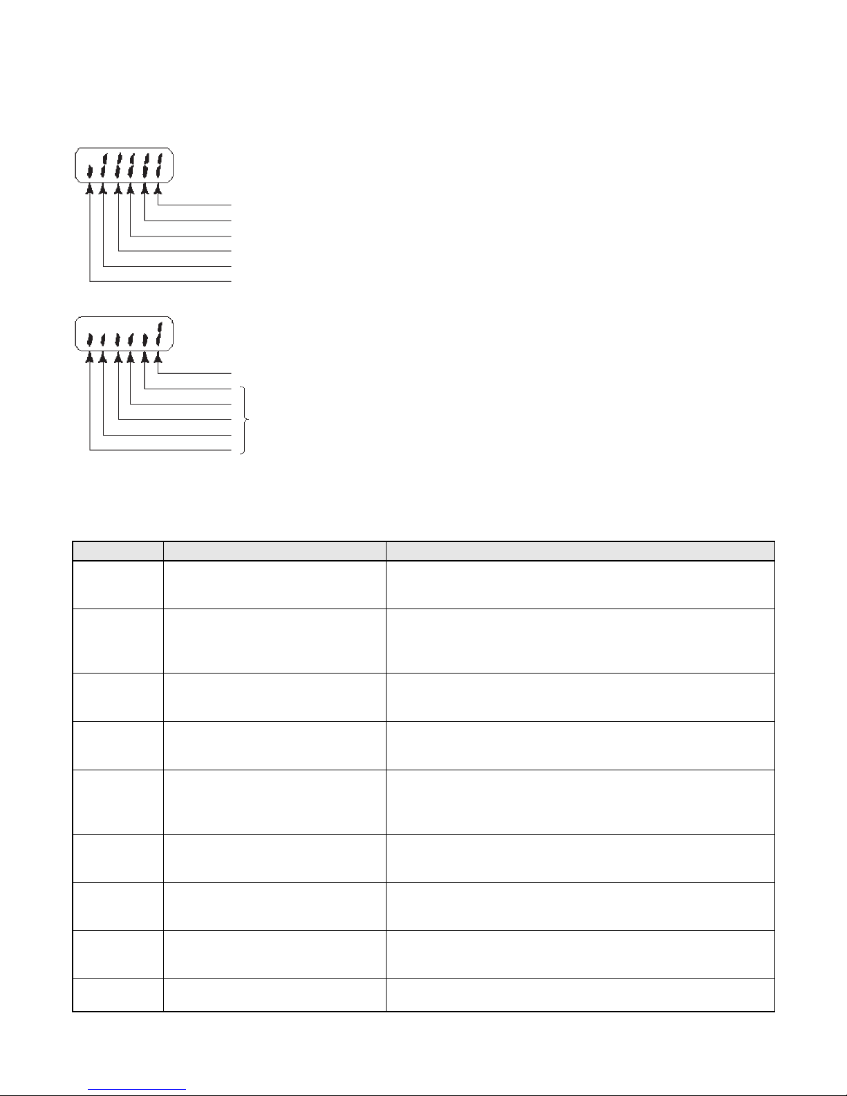
Input/Output terminal status
Input Terminal Status
1: Terminal S1 is “closed”
1: Terminal S2 is “closed”
1: Terminal S3 is “closed”
1: Terminal S4 is “closed”
1: Terminal S5 is “closed”
Not Used
Output Terminal Status
1: Terminal MA-MC is “closed”
Not Used
7. Faults and Alarms
Fault Display Fault name and meaning Possible cause and remedy
OC Overcurrent
Output current is higher than 250% of
inverter rated current.
OV Overvoltage
DC bus voltage has exceeded
detection level.
uV1 Main circuit undervoltage
DC bus voltage is below detection
level.
OH Unit overheated
Temperature inside the inverter has
exceeded 110°C.
OL1 Motor overload
The inverter is protecting the motor
from overload based on an internal IT
*1
EF
SER
(flashing)
bb
(flashing)
EF
(flashing)
calculation using n036 setting.
External fault
An external fault has been input.
Sequence error
Sequence input when inverter
running.
External baseblock
An external baseblock command has
been input.
Sequence error has occured Forward and reverse run signal have been applied simultaneously.
Check output for short circuit or ground fault.
The Load is too large, reduce it ore use larger Inverter.
Check motor FLA rating compared to inverter and V/F setting.
Load inertia is too large and the motor is regenerating.
Increase deceleration time (n020 or n022).
Connect an external braking resistor and set n092 to 1.
Check braking resistor and wiring.
Check mains power supply voltage and connections.
Check correct supply for Inverter being used.
Monitor for mains dips or interruptions.
Refer to manual for installation guidelines and recommendations.
Check cooling fan (if fitted).
Check V/F characteristic ore reduce Carrier frequency.
Check and reduce the load.
Check V/F characteristic (V
Increase the running speed of the motor.
Increase acceleration/decelleration times.
Check your control terminal wiring.
A multi-functional digital input has been set to 3 or 4.
Run signal must be removed before this can be reset.
Inverter must be stopped when Local/Remote switching attempted.
Inverter must be stopped when Comms/Remote switching
attempted
Check your control terminal wiring.
A multi-functional digital input has been set to 12 or 13.
max
and F
max
).
*1 Refer to user’s manual for full fault code listings
Page 28

Page 29

VS MINI J7
Kurzanleitung
1. Anschlussplan
2. Steuerklemmen
DEUTSCH
3. Installation
4. Inbetriebnahme und Testlauf
5. Parameterübersicht
6. Überwachungsanzeige
7. Fehler und Alarme
Page 30
1. Anschlussplan
200 V AC (Drehstrom
oder Wechselstrom,
siehe Hinweis 1)
Externer
Frequenzeinsteller
(Potentiometer)
(2 kΩ min. 1/4 W)
3G3JV PFI @
Entstörfilter
L1
L2
L3
Vorwärts/Stopp
Multifunktionseingang 1 (S2)
Multifunktionseingang 2 (S3)
Multifunktionseingang 3 (S4)
Multifunktionseingang 4 (S5)
Bezugspotenzial
Frequenzsollwert-Spannungsversorgung
(20 mA bei 12 V DC)
Frequenzsollwerteingang
Frequenzsollwert-Bezugspotenzial
L1i
L2i
L3i
+1 +2 -
R/L1
S/L2
T/L3
S1
S2
S3
S4
S5
SC
FS
FR
FC
Brücke
W/T3
U/T1
V/T2
MA
MB
MC
AM
Multifunktionskontaktausgang
Schließer
Öffner
Bezugspunkt
Analoger
Überwachungsausgang
AC
Bezugspotenzial analoger
Überwachungsausgang
M
Hinweis 1: 200 V Wechselspannung: Anschluss an die Klemmen R/L1 und S/L2.
Hinweis 2: Der Frequenzumrichter verfügt über keinen Bremstransistor, daher kann kein Bremswiderstand
angeschlossen werden.
Erdungsklemme
Versorgungsspannungseingangsklemmen
Steuerklemmen
Anordnung der Steuerklemmen
Motorausgangsklemmen
Erdungsklemme
Page 31

2. Steuerklemmen
Symbol Bezeichnung Funktion Signalspezifikation
Eingänge
Ausgänge
*1 Werkseinstellung: NPN-Spannungseingänge. Keine externe Spannungsversorgung erforderlich (siehe nachstehende
*2 Bei den Funktionsangaben in Klammern handelt es sich um die Standardeinstellungen.
S1 Vorwärts/Stopp EIN: Vorwärtslauf / AUS: Stopp Optokoppler (8 mA
S2 Multifunktionseingang 1 Bestimmt durch Parameter n36 (Rückwärtslauf/Stopp)
S3 Multifunktionseingang 2 Bestimmt durch Parameter n37 (Externer Fehler,
Schließer)
S4 Multifunktionseingang 3 Bestimmt durch Parameter n38 (Fehlerrücksetzung)
S5 Multifunktionseingang 4 Bestimmt durch Parameter n39 (Multistep-Sollwert 1)
SC Bezugspotenzial
Multifunktionseingänge
FS Frequenzsollwert-
Spannungsversorgung
FR Frequenzsollwert-Eingang Eingangsklemme für die Einstellung des
FC Bezugspotenzial Frequenzsollwert Bezugspotenzial für die Einstellung des
MA MBMultifunktionsausgang: Schließer
Multifunktionsausgang: Öffner
MC Multifunktionsausgang-Bezugspunkt Bezugspunkt für MA und MB
AM Analoger Überwachungsausgang Bestimmt durch Parameter n44 (Ausgangsfrequenz)
AC Bezugspotenzial analoger
Überwachungsausgang
Gemeinsames Bezugspotenzial für die Eingänge S1
bis S5
DC-Spannungsversorgung für die Einstellung des
Frequenzsollwerts
Frequenzsollwerts
Frequenzsollwerts
Bestimmt durch Parameter n40 (während des Betriebs)
Bezugspotenzial für die Klemme AM
*2
*2
bei 24 V DC
*2
*2
20 mA bei 12 V DC
0 bis 10 V DC (20 kΩ)
4 bis 20 mA
0 bis 20 mA
*2
Relaisausgang
(max. 1 A bei 30 V DC
bzw. 250 VAC)
*2
0 bis 10 V DC,
max. 12 mA
Anschlussdiagramme)
*1
)
Auswahl der Eingangspolarität
Mithilfe der Schalter SW7 und SW8
oberhalb des Steuerklemmenblocks
SW7
PNP
kann die Eingangspolarität und die Art
des Eingangs (Strom- oder Spannungs-
NPN
eingang) umgeschaltet werden.
Diese Schalter befinden sich hinter der
SW7
Frontabdeckung.
Auswahl der Eingangspolarität
Mithilfe des Schalters SW7 kann die Eingangspolarität wie dargestellt
zwischen NPN und PNP umgeschaltet werden.
NPN
(Standardeinstellung)
S1 bis S5
SC
GND
3,3 k
0,1µ
GND
SW7
24 V
360
PNP
24 V DC
(±10 %)
U
OFF
SW8
I
SW8
S1 bis S5
SC
GND
3,3 k
0,1µ
GND
SW7
Steuerklemmenblock
Steuerklemmenblock
24 V
360
Page 32

3. Installation
Zwei Bohrungen Ø 5
,
Nennspannung
Drehstrom
200 V AC
Wechselstrom
200 V AC
Drehstrom
400 V AC
Modell
J7AZ
20P1 68 128 70 56 118 5 2
20P2 68 128 70 56 118 5 2
20P4 68 128 102 56 118 5 2
20P7 68 128 122 56 118 10 2
21P5 108 128 129 96 118 20 2
22P2 108 128 154 96 118 20 3,5
24P0 140 128 161 128 118 30 5,5
B0P1 68 128 70 56 118 5 2
B0P2 68 128 70 56 118 5 2
B0P4 68 128 112 56 118 10 2
B0P7 108 128 129 96 118 20 3,5
B1P5 108 128 154 96 118 20 5,5
40P2 108 128 81 96 118 5 2
40P4 108 128 99 96 118 5 2
40P7 108 128 129 96 118 5 2
41P5 108 128 154 96 118 10 2
42P2 108 128 154 96 118 10 2
43P0 140 128 161 128 118 20 2
44P0 140 128 161 128 118 20 2
Abmessungen (mm) Zuleitungen
B H T B1 H1
Leistungsschalter (A)
Draht (mm²)
Entstörfilter
Modell
J7AZ
20P1 PFI2010-SE 82 194 50 92 181 5,3
20P2
20P4
20P7
21P5 PFI2020-SE 111 169 50 91 156 5,3
22P2
24P0 PFI2030-SE 144 174 50 120 161 5,3
B0P1 PFI1010-SE 71 169 45 51 156 5,3
B0P2
B0P4
B0P7 PFI1020-SE 111 169 50 91 156 5,3
B1P5
Filter
3G3JV-
Abmessungen
B L H Y X d
Page 33

Modell
J7AZ
Filter
3G3JV-
Abmessungen
B L H Y X d
40P2 PFI3005-SE 111 169 50 91 156 5,3
40P4
40P7 PFI3010-SE 111 169 50 91 156 5,3
41P5
42P2
43P0 PFI3020-SE 144 174 50 120 161 5,3
44P0
Installation von Entstörfilter und Frequenzumrichter
Schaltschrank Schaltschrank
Schaffner
DrehstromEntstörfilter
Frequenzumrichter
der
J7-Serie
Montageplatte
(Metall)
Erdungs-
flächen
(sämtliche
Farbe vor
der
Montage
entfernen)
Schaffner
DrehstromEntstörfilter
Frequenzumrichter
der
J7-Serie
KabelschirmKabelschirm
Montageplatte
(Metall)
Erdungs-
flächen
(sämtliche
Farbe vor
der
Montage
entfernen)
Erdungsflächen (sämtliche
Farbe vor der Montage entfernen)
Kabelschirm
Motorzuleitung
(max. 20 m)
Erdungsflächen (sämtliche
Farbe vor der Montage entfernen)
Kabelschirm
Motorzuleitung
(max. 20 m)
CIMR-J7@@@@20P1 bis 24P0 CIMR-J7@@@@B0P1 bis B4P0
CIMR-J7@@@@40P2 bis 44P0
Page 34

Einbauabmessungen
min. 30 mmmin. 30 mm
Luft
Luft
min. 100 mm min. 100 mm
4. Inbetriebnahme und Testlauf
Datenanzeige
Tasten
Anzeige Bezeichnung Funktion
Datenanzeige Anzeige relevanter Daten wie Frequenzsollwert, Ausgangsfrequenz und
eingestellte Parameterwerte.
FREQ-Einsteller Einstellung des Frequenzsollwerts auf einen zwischen 0 Hz und der
Maximalfrequenz liegenden Wert.
FREF-Anzeige Wenn diese Anzeige leuchtet, wird der Frequenzsollwert angezeigt und
kann eingestellt werden.
FOUT-Anzeige Wenn diese Anzeige leuchtet, wird die Ausgangsfrequenz des
Frequenzumrichters angezeigt und kann eingestellt werden.
IOUT-Anzeige Wenn diese Anzeige leuchtet, wird der Ausgangsstrom des
Frequenzumrichters angezeigt.
MNTR-Anzeige Wenn diese Anzeige leuchtet, können die durch U01 bis U10 bestimmten
Betriebsparameterwerte angezeigt werden.
F/R-Anzeige Wenn diese Anzeige leuchtet, kann die Drehrichtung ausgewählt werden,
die bei Aktivierung des Frequenzumrichters mit der RUN-Taste verwendet
wird.
Anzeigen
(Einstellung/
Anzeige)
FREQ-Einsteller
Page 35

Anzeige Bezeichnung Funktion
LO/RE-Anzeige Wenn diese Anzeige leuchtet, kann ausgewählt werden, ob der Betrieb
des Frequenzumrichters über die digitale Bedienkonsole oder gemäß der
eingestellten Parameter erfolgt.
Hinweis: Der Status dieser Einstellung kann nur bei laufendem
PRGM-Anzeige Wenn diese Anzeige leuchtet, können die Parameter n01 bis n79 ange-
zeigt und eingestellt werden.
Hinweis: Während des Frequenzumrichterbetriebs können die Parameter
Betriebsarten-Taste Wechselt der Reihe nach durch die o. a. Anzeige- und Einstellungsanzeigen.
Ungespeicherte Änderungen an Parametereinstellungen werden
verworfen, wenn diese Taste gedrückt wird.
Erhöhen-Taste Erhöhen von Parameternummern (Anzeige und Einstellung) und
Parameter-Einstellungen.
Verringern-Taste Verringern von Parameternummern (Anzeige und Einstellung) und
Parameter-Einstellungen.
Eingabetaste Übernahme von Parameternummern (Anzeige und Einstellung),
Übernahme geänderter Parametereinstellungen.
Frequenzumrichterbetrieb angezeigt werden. RUN-Befehle werden
ignoriert, solange diese Anzeige leuchtet.
lediglich angezeigt werden. Nicht alle Parameter können eingestellt
werden. RUN-Befehle werden ignoriert, solange diese Anzeige
leuchtet.
RUN-Taste Starten des Frequenzumrichters, sofern diese Taste nicht durch eine
entsprechende Parametereinstellung gesperrt ist.
STOP/RESET-Taste Stoppen des Frequenzumrichters, sofern die STOP-Taste nicht durch eine
entsprechende Einstellung des Parameters n06 deaktiviert wurde.
Die folgenden sieben Schritte beschreiben die Vorgehensweise zur Inbetriebnahme des Frequenzumrichters, um in kürzester Zeit den einfachen
Betrieb eines Motors in einer typischen Konfiguration zu ermöglichen:
Schritt 1 – Grundüberprüfungen
1-1 Vor dem Anschluss der Versorgungsspannung durchzuführende Überprüfungen.
Kontrollieren Sie die Versorgungsspannung:
CIMR-J7AZ2@@@: Drehstrom 200 bis 230 V AC
CIMR-J7AZB@@@: Wechselstrom 200 bis 240 V AC (Anschluss an R/L1 und S/L2)
CIMR-J7AZ4@@@: Drehstrom 380 bis 460 V AC
1-2 Kontrollieren Sie den korrekten Anschluss des Motors an die Motorausgangsklemmen (U/T1,
V/T2, W/T3).
1-3 Kontrollieren Sie den korrekten Anschluss des Steuerschaltkreises an die Steuerklemmen.
1-4 Stellen Sie sicher, dass alle Steuerklemmen auf AUS geschaltet sind.
1-5 Trennen Sie den Motor von der Last.
Schritt 2 – Anschließen der Spannungsversorgung und Überprüfen des
Anzeigestatus
2-1 Schließen Sie nach Durchführen der Überprüfungen in Schritt 1 die Spannungsversorgung an
den Frequenzumrichter an.
2-2 Treten beim Anschließen und Einschalten der Spannungsversorgung keine Fehler auf, zeigt die
Anzeige das folgende Verhalten:
Page 36

RUN-Anzeige: blinkt.
ALARM-Anzeige: aus
Sonstige Anzeigen (Einstellung/Anzeige): FREF, FOUT oder IOUT leuchtet.
Datenanzeige: zeigt die entsprechenden Daten (Frequenzsollwert, Ausgangsfrequenz oder
Ausgangsstrom) an.
Trat beim Einschalten der Versorgungsspannung ein Fehler auf, werden die Details des Fehlers
angezeigt. Konsultieren Sie in diesem Fall die Bedienungsanleitung, und ergreifen Sie die erforderlichen Maßnahmen.
Schritt 3 – Initialisieren der Parameter
Zum Zurücksetzen der Frequenzumrichter-Parameter auf die Werkseinstellungen setzen Sie den
Parameter n01 auf 8. In dieser Einstellung erfolgt die Ansteuerung des Frequenzumrichters im so
genannten Zweidrahtbetrieb, d. h. ein Multifunktionseingang („Draht“) fungiert als Vorwärts/StoppBefehl, ein weiterer als Rückwärts/Stopp-Befehl.
Tastenfolge
Nach etwa einer
Sekunde
Anzeige
Datenanzeige
(Beispiel)
Erläuterung
Spannung EIN
Drücken Sie wiederholt die Mode Key, bis die PRGM-Anzeige
leuchtet.
Drücken Sie die Eingabetaste. Nun wird die aktuelle Einstellung des
Parameters n01 angezeigt.
Stellen Sie mithilfe der Erhöhen- oder Verringern-Taste den Wert 8
ein. Dabei blinkt die Datenanzeige.
Drücken Sie die Eingabetaste, damit der geänderte Wert
übernommen wird. Anschließend wird der Wert nicht mehr blinkend,
sondern konstant leuchtend angezeigt.
Die Parameternummer wird wieder angezeigt.
Schritt 4 – Einstellung des Motornennstroms
Dieser Parameter regelt das Verhalten des elektronischen Thermorelais für den Motorüberlastschutz
(OL1). Bei korrekter Einstellung dieses Parameters verhindert der Frequenzumrichter das Durchbrennen des Motors bei Überlastung.
Lesen Sie den auf dem Typenschild des Motors angegebenen Nennstrom (A) ab, und stellen Sie den
Parameter n32 auf diesen Wert. Das folgende Beispiel zeigt die Einstellung des Werts 1,8 A.
Tastenfolge
Nach etwa einer
Sekunde
Anzeige
Datenanzeige
(Beispiel)
Erläuterung
Anzeige der Parameternummer.
Stellen Sie mithilfe der Erhöhen- oder Verringern-Taste den
Parameter n32 ein.
Drücken Sie die Eingabetaste. Nun wird die aktuelle Einstellung des
Parameters n32 angezeigt.
Stellen Sie mithilfe der Erhöhen- oder Verringern-Taste den
Motornennstrom ein. Dabei blinkt die Datenanzeige.
Drücken Sie die Eingabetaste, damit der geänderte Wert übernommen wird. Anschließend wird der Wert nicht mehr blinkend, sondern
konstant leuchtend angezeigt.
Die Parameternummer wird wieder angezeigt.
Page 37

Schritt 5 – Einstellung der Motornennfrequenz
Die Motornennfrequenz gibt die maximale Betriebsfrequenz des Motors an. Der Frequenzumrichter
benötigt diese Angabe, um den Motor ordnungsgemäß ansteuern zu können. Lesen Sie die auf dem
Typenschild des Motors angegebene Nennfrequenz (Hz) ab, und stellen Sie die Parameter n09 und
n11 auf diesen Wert.
Schritt 6 – Einstellen der Befehlsquelle
Legen Sie fest, wie die Start- und Stoppbefehle gegeben werden. Dies kann wahlweise über die RUNund die STOP/RESET-Taste oder über entsprechende Signale an Multifunktionseingängen erfolgen.
Die Einstellung der Befehlsquelle erfolgt durch Setzen des Parameters n02 auf den entsprechenden
Wert:
0: Die RUN- und die STOP/RESET-Taste sind aktiviert.
1: Start- und Stoppbefehle werden über Steuerklemmen gegeben.
Das nachstehende Diagramm zeigt den Anschluss eines Schalters zum Starten/Stoppen des Motors
im Vorwärtslauf im so genannten Zweidrahtbetrieb. Dazu muss der Parameter n02 auf 1 gesetzt sein.
Um mit einem weiteren Schalter an Steuerklemme S2 den Rückwärtslauf zu aktivieren, muss zusätzlich der Parameter n36 auf 2 gesetzt sein (Standardeinstellung).
Vorwärts
Start/Stopp
Rückwärts
Start/Stopp
Schritt 7 – Einstellen des Frequenzsollwerts
Legen Sie fest, wie die Drehzahl des Motors eingestellt wird. Standardmäßig erfolgt dies mithilfe des
FREQ-Einstellers, bei dessen Verwendung keine weiteren Einstellungen erforderlich sind.
Der Frequenzsollwert kann auch mittels eines externen Potenziometers oder eines analogen SPSAusgangs geregelt oder auf einen von acht im Frequenzumrichter vorprogrammierten und vermittels
der Multifunktionseingänge ausgewählten Werten gesetzt werden.
Um beispielsweise den Frequenzsollwert mittels eines externen Potenziometers oder eines analogen
SPS-Ausgangs zu regeln, muss der Parameter n03 auf 2 gesetzt werden.
Frequenz-
( )
einstellungsSpannungsversorgung
+12 V, 20 mA
FR
Drehzahlsollwert
(0 bis +10 V)
FC (0 V)
Page 38

5. Parameterübersicht
*1
Parameter-Nr. Beschreibung Bereich Standardeinstellung
n01 Parameterschutz:
0: Beschränkter Zugriff auf die Parameter
1: Vollständiger Zugriff auf die Parameter
8: Zurücksetzen der Parameter auf die
Werkseinstellungen
n02 Befehlsquelle:
0: Bedientasten
1: Steuerklemmen
2: Kommunikation (Option)
n03 Frequenzsollwertquelle:
0: FREQ-Einsteller
1: Frequenzsollwert 1 (n21)
2: Steuerklemme (0 bis 10 V)
3: Steuerklemme (4 bis 20 mA)
4: Steuerklemme (0 bis 20 mA)
6: Kommunikation (Option)
n09 Maximale Ausgangsfrequenz 50 bis 400 Hz
n10 Maximale Ausgangsspannung 1 bis 255V (200-V-Klasse)
n11 Maximale Ausgangsfrequenz 50 bis 400 Hz
n16 Beschleunigungszeit 1 0,0 bis 999 s 10 s
n17 Verzögerungszeit 2 0,0 bis 999 s 10 s
n21 Frequenzsollwert 1 0,0 bis 400 Hz 50 Hz
n22 bis n28 Frequenzsollwert 2 bis 8 0,0 bis 400 Hz 0 Hz
n32 Motornennstrom Modellabhängig 0 bis 120 % des Frequenz-
n36 bis n39 Multifunktionseingänge S2 bis S5 0 bis 35 -n40 Multifunktionsausgänge (MA/MB) 0 bis 18 1
n44 Analoger Multifunktionsausgang (AM):
0: Ausgangsfrequenz (10 V = Maximalfrequenz)
1: Ausgangsstrom (10 V = Frequenzumrichter-
nennstrom)
n46 Trägerfrequenz 1 bis 4 (2,5 bis 10 kHz)
n52 DC-Bremsstrom 0 bis 100 % 50 %
n53 DC-Bremsstrom beim Stopp 0 bis 100 % 50 %
n54 DC-Bremsstrom beim Start 0 bis 100 % 50 %
n55 Blockierschutz bei Verzögerung:
0: Aktiviert
1: Deaktiviert
0 bis 9 1
0 bis 2 0
0 bis 4, 6 0
200 V (200-V-Klasse)
1 bis 510V (400-V-Klasse)
0,1 0
7 bis 9 (proportional zur
Ausgangsfrequenz)
0,1 0
400 V (400-V-Klasse)
umrichternennstroms
Modellabhängig
Multifunktionseingänge Multifunktionsausgänge
Einstellung*1Funktion Einstellung*1Funktion
2 Rückwärts/Stopp 0 Fehlerausgang
3 Externer Fehler (Schließer) 1 In Betrieb
4 Externer Fehler (Öffner) 2 Frequenzübereinstimmung
5 Fehlerrücksetzung 6 Drehmomentüberschreitung wird überwacht
6 Multistep-Drehzahlsollwert 1 12 RUN-Betriebsart
*1 Eine vollständige Liste finden Sie in der Bedienungsanleitung.
(Schließer)
Page 39

Multifunktionseingänge Multifunktionsausgänge
Einstellung*1Funktion Einstellung*1Funktion
7 Multistep-Drehzahlsollwert 2 13 Frequenzumrichter bereit
8 Multistep-Drehzahlsollwert 3 15 Unterspannung
10 Tippbetrieb
12 Externe Endstufensperre (Schließer)
13 Externe Endstufensperre (Öffner) 0 Ausgangsfrequenz
17 Umschaltung Lokal / Dezentral 1 Ausgangsstrom
*1 Eine vollständige Liste finden Sie in der Bedienungsanleitung.
Analoger Überwachungsausgang
Einstellung*1Funktion
Parametereinstellungen (Beispiel)
Änderungen
verwerfen
Nach etwa einer Sekunde
TastenFolge
Nach etwa einer
Sekunde
Anzeige
Datenanzeige
(Beispiel)
Erläuterung
Spannung EIN
Drücken Sie wiederholt die Mode Key, bis die PRGM-Anzeige
leuchtet.
Stellen Sie mithilfe der Erhöhen- oder Verringern-Taste die
Parameternummer ein.
Drücken Sie die Eingabetaste. Nun wird die aktuelle Einstellung
des ausgewählten Parameters angezeigt.
Stellen Sie mithilfe der Erhöhen- oder Verringern-Taste den
gewünschten Wert ein.
Dabei blinkt die Datenanzeige.
Drücken Sie die Eingabetaste, um den geänderten Wert zu
übernehmen. Anschließend wird der Wert nicht mehr blinkend,
sondern konstant leuchtend angezeigt (siehe Hinweis 1).
Die Parameternummer wird wieder angezeigt.
Hinweis1: Wenn Sie die geänderte Parametereinstellung nicht übernehmen, sondern verwerfen
möchten, drücken Sie einfach stattdessen die Betriebsartentaste. Anschließend wird
wieder die Parameternummer angezeigt.
2: Bestimmte Parameter können während des laufenden Frequenzumrichterbetriebs nicht
geändert werden (siehe Parameterliste). Wenn Sie versuchen, einen dieser Parameter zu
ändern, zeigt die Datenanzeige beim Drücken der Erhöhen- oder Verringern-Taste keine
Änderung.
Page 40

6. Überwachungsanzeige
Der Frequenzumrichter VS Mini J7 ermöglicht die kontinuierliche Anzeige bestimmter Betriebsparameter (z. B. Ausgangsstrom oder Status der Multifunktionseingänge).
Diese Überwachung erfolgt mithilfe der „U“-Parameter.
Tastenfolge Anzeige
Einstellung Bezeichnung Beschreibung
U01 Frequenzsollwert
(FREF)
U02 Ausgangsfrequenz
(FOUT)
U03 Ausgangsstrom
(IOUT)
U04 Ausgangsspannung V Anzeige der Ausgangsspannung
U05 Zwischenkreisspannung V Anzeige der Zwischenkreisspannung
U06 Eingangsklemmenstatus -- Anzeige des Status der Steuerklemmen
U07 Ausgangsklemmenstatus -- Anzeige des Status der Ausgangsklemmen
U09 Fehlerspeicher -- Anzeige der letzten vier Fehler
U10 Software-Nummer -- Anzeige der Software-Nummer
U15 Datenempfangsfehler -- Anzeige des Inhalt des MEMOBUS-Kommunikations-Datenempfangs-
Datenanzeige
(Beispiel)
Hz Anzeige des Frequenzsollwerts (entspricht FREF)
Hz Anzeige der Ausgangsfrequenz (entspricht FOUT)
A Anzeige des Ausgangsstroms (entspricht IOUT)
Erläuterung
Spannung EIN
Drücken Sie wiederholt die Betriebsartentaste, bis die MNTRAnzeige leuchtet. Nun wird U01 angezeigt.
Stellen Sie mithilfe der Erhöhen- oder Verringern-Taste den
anzuzeigenden/zu überwachenden Betriebsparameter ein.
Drücken Sie die Eingabetaste. Nun wird der Wert des
ausgewählten Betriebsparameters kontinuierlich angezeigt.
Durch erneutes Drücken der Betriebsartentaste wird wieder die
Nummer des angezeigten Betriebsparameters angezeigt.
fehler-Registers (entspricht dem Übertragungsregisters 003Dh)
Page 41

Eingangs-/Ausgangsklemmenstatus
Eingangsklemmenstatus
1: Klemme S1 ist auf EIN gesetzt
1: Klemme S2 ist auf EIN gesetzt
1: Klemme S3 ist auf EIN gesetzt
1: Klemme S4 ist auf EIN gesetzt
1: Klemme S5 ist auf EIN gesetzt
Nicht verwendet
Ausgangsklemmenstatus
1: Kontakt MA-MC ist geschlossen
Nicht verwendet
7. Fehler und Alarme
Fehleranzeige Bezeichnung und Bedeutung Mögliche Ursachen und Abhilfemaßnahmen
OC Überstrom
OV Überspannung
UV1 Zwischenkreisunterspannung
OH Überhitzung
OL1 Motorüberlastung
*1
EF
SER
(blinkend)
bb
(blinkend)
EF
(blinkend)
Der Ausgangsstrom beträgt mehr
als 250 % des Frequenzumrichternennstroms.
Die Zwischenkreisspannung
übersteigt den ÜberspannungsErkennungspegel.
Die Zwischenkreisspannung
unterschreitet den UnterspannungsErkennungspegel.
Die Temperatur im Inneren des Frequenzumrichters hat 110 °C überschritten.
Der Frequenzumrichter schützt den
Motor mittels interner, auf dem Wert
des Parameters n036 basierender
Berechnungen vor Überlastung.
Externer Fehler
Dem Frequenzumrichter wurde ein
externer Fehler signalisiert.
Sequenzfehler
Sequenzeingabe bei laufendem
Frequenzumrichter.
Externe Endstufensperre
Ein externer Endstufensperrbefehl
wurde gegeben.
Sequenzfehler Vorwärts- und Rückwärtslaufsignal wurden gleichzeitig angelegt.
Ausgang auf Kurz- oder Erdschluss überprüfen.
Die Last ist zu groß. Last reduzieren oder leistungsfähigeren Frequenzumrichter einsetzen.
Maximalen Motorstrom in Hinsicht auf maximalen Frequenzumrichterausgangsstrom und U/f-Einstellung überprüfen.
Beim generatorischen Betrieb des Motors ist die Massenträgheit
der Last zu groß. Verzögerungszeit (n020 oder n022) vergrößern.
Externe Bremseinheit anschließen und n092 auf 1 setzen.
Bremswiderstand und Verdrahtung überprüfen.
Versorgungsspannung und Anschlüsse überprüfen.
Eignung der Versorgungsspannung für den Frequenzumrichter
überprüfen. Versorgungsspannung auf Spannungseinbrüche und unterbrechungen überwachen.
Richtlinien und Empfehlungen der Bedienungsanleitung beachten.
Kühllüfter (sofern vorhanden) überprüfen.
U/f-Kennlinie überprüfen oder Trägerfrequenz reduzieren.
Last überprüfen und ggf. reduzieren.
U/f-Kennlinie (U
Motordrehzahl erhöhen.
Beschleunigungs-/Verzögerungszeiten erhöhen.
Verdrahtung des Steuerschaltkreises überprüfen.
Einer der Parameter für die Funktion der Multifunktionseingänge
wurde auf 3 oder 4 gesetzt. Dieser Fehlerzustand kann erst nach
Aufheben des RUN-Signals gelöscht werden.
Umschaltung zwischen lokaler und dezentraler Steuerung kann nur
bei angehaltenem Frequenzumrichter erfolgen.
Umschaltung zwischen Kommunikations- und dezentraler Steuerung kann nur bei angehaltenem Frequenzumrichter erfolgen.
Verdrahtung des Steuerschaltkreises überprüfen.
Einer der Parameter für die Funktion der Multifunktionseingänge
wurde auf 12 oder 13 gesetzt.
max
und f
) überprüfen.
max
*1 Eine vollständige Fehlercode-Liste finden Sie in der Bedienungsanleitung.
Page 42

Page 43

VARIADOR DE VELOCIDAD J7
Guía rápida
1. Cableado
2. Terminales del circuito de control
ESPAÑOL
3. Instalación
4. Inicio y prueba de funcionamiento
5. Lista rápida de parámetros
6. Monitorización
7. Fallos y alarmas
Page 44

1. Cableado
Trifásica de 200 V c.a.;
monofásica de 200 V
c.a. (ver nota 1)
Potenciómetro
externo de ajuste
de frecuencia
3G3JV PFI @
Filtro de ruido
L1
L2
L3
Marcha directa/parada
Entrada multifuncional 1 (S2)
Entrada multifuncional 2 (S3)
Entrada multifuncional 3 (S4)
Entrada multifuncional 4 (S5)
Común de entrada de secuencia
Alimentación de referencia de
frecuencia 20 mA a +12 V
Entrada de referencia de frecuencia
Común de referencia de frecuencia
L1i
L2i
L3i
+1 +2 -
R/L1
S/L2
T/L3
S1
S2
S3
S4
S5
SC
FS
FR
FC
PUENTE
U/T1
V/T2
W/T3
Salida de contacto multifuncional
MA
NA
MB
NC
MC
Común
AM
Salida de monitorización analógica
AC
Común de salida de
monitorización analógica
M
Nota 1: Conecte la alimentación monofásica de 200 V c.a. a los terminales R/L1 y S/L2 del J7AZB
Nota 2: La resistencia de freno no puede conectarse porque no hay incorporado un transistor de freno.
Terminal
de masa
Terminales de entrada
del circuito principal
Disposición de los terminales del circuito
Terminales de
salida del
circuito principal
Terminales del
circuito de
control
Terminal
de masa
de control
Page 45

2. Terminales del circuito de control
Símbolo Nombre Función Nivel de la señal
Entrada S1 Marcha directa/Parada Marcha directa: ON, Parada: OFF Fotoacoplador de
S2 Entrada multifuncional 1 Configurada mediante el parámetro n36
(Inversa/Parada)
S3 Entrada multifuncional 2 Configurada mediante el parámetro n37
(Fallo externo: NA)
S4 Entrada multifuncional 3 Configurada mediante el parámetro n38
(Reset de fallo)
S5 Entrada multifuncional 4 Configurada mediante el parámetro n39
(Referencia de multivelocidad 1)
*2
*2
*2
*2
SC Común de entrada de secuencia Común para S1 hasta S5
FS Alimentación eléctrica de referencia
de frecuencia
Alimentación eléctrica de c.c. para uso de
referencia de frecuencia
FR Entrada de referencia de frecuencia Terminal de entrada para uso de referencia de
frecuencia
FC Común de referencia de frecuencia Común para uso de referencia de frecuencia 4 a 20 mA
Salida MA MBSalida multifuncional: NA
Salida multifuncional: NC
Configurada por el parámetro n40 (durante el
funcionamiento)
*2
MC Común de salida multifuncional Común para uso de MA y MB
AM Salida de monitorización analógica Configurada mediante el parámetro n44
(Frecuencia de salida)
AC Común de salida de monitorización
Común para uso de AM
*2
analógica
8mA a 24Vc.c.
20 mA a 12 V c.c.
0 a 10 V c.c. (20 kΩ)
0 a 20 mA
Salida de relé 1 A
máx. a 30 V c.c. y
250 V c.a.
12 mA máx. a 0
hasta 10 V c.c.
*1
*1 La configuración de estos terminales es NPN. No se requiere una fuente de alimentación externa. Consulte las
conexiones que se indican a continuación
*2 Las funciones entre paréntesis indican la configuración predeterminada.
Selección del método de entrada
PNP
NPN
SW7
SW7
V
OFF
SW8
I
SW8
Bloque de
terminales del
circuito de control
Bloque de
terminales del
circuito de control
Los interruptores SW7 y SW8, ambos situados sobre los terminales
del circuito de control, se utilizan
para la selección del método de
entrada.
Para utilizar estos interruptores, retire la cubierta delantera y la cubierta opcional.
Selección de entrada de secuencia
La entrada puede seleccionarse empleando SW7, NPN o PNP, tal y como se indica a continuación
NPN
(Configuración
predeterminada)
S1 a 5
SC
GND
3,3 k
0,1 µ
GND
SW7
24 V
360
PNP
24 V c.c.
(± 10%)
S1 a 5
SC
GND
3,3 k
0,1 µ
GND
SW7
24 V
360
Page 46

3. Instalación
Dos orificios de 5 de diá.
,
Tensión
nominal
Trifásica de
200 V c.a.
Monofásica de
200 V c.a.
Trifásica de
400 V c.a.
Modelo
J7AZ
20P1 68 128 70 56 118 5 2
20P2 68 128 70 56 118 5 2
20P4 68 128 102 56 118 5 2
20P7 68 128 122 56 118 10 2
21P5 108 128 129 96 118 20 2
22P2 108 128 154 96 118 20 3.5
24P0 140 128 161 128 118 30 5.5
B0P1 68 128 70 56 118 5 2
B0P2 68 128 70 56 118 5 2
B0P4 68 128 112 56 118 10 2
B0P7 108 128 129 96 118 20 3.5
B1P5 108 128 154 96 118 20 5.5
40P2 108 128 81 96 118 5 2
40P4 108 128 99 96 118 5 2
40P7 108 128 129 96 118 5 2
41P5 108 128 154 96 118 10 2
42P2 108 128 154 96 118 10 2
43P0 140 128 161 128 118 20 2
44P0 140 128 161 128 118 20 2
Dimensiones (mm)
A H F A1 H1 MCCB (A) Hilo (mm²)
Línea y protección
recomendada
Especificaciones del filtro de ruido
Modelo
J7AZ
20P1 PFI2010-SE 82 194 50 92 181 5,3
20P2
20P4
20P7
21P5 PFI2020-SE 111 169 50 91 156 5,3
22P2
24P0 PFI2030-SE 144 174 50 120 161 5,3
B0P1 PFI1010-SE 71 169 45 51 156 5,3
B0P2
B0P4
B0P7 PFI1020-SE 111 169 50 91 156 5,3
B1P5
Filtro
3G3JV-
Dimensiones
A L H Y X f
Page 47

Modelo
J7AZ
Filtro
3G3JV-
Dimensiones
A L H Y X f
40P2 PFI3005-SE 111 169 50 91 156 5,3
40P4
40P7 PFI3010-SE 111 169 50 91 156 5,3
41P5
42P2
43P0 PFI3020-SE 144 174 50 120 161 5,3
44P0
Instalación del filtro de ruido y J7
Cable
apantallado
Panel de control Panel de control
Filtro trifásico
Schaffner
RFI
Placa de mon-
taje metálica
Conexio-
nes a ma-
sa (quite
la pintura)
Filtro trifásico
Schaffner
RFI
Variador
serie J7
Conexiones a masa (quite la pintura)
Cable
apantallado
Cable del motor:
máx. 20 m
Conexiones a masa (quite la pintura)
Variador
serie J7
Cable
apantallado
Placa de mon-
taje metálica
Conexio-
nes a ma-
sa (quite
la pintura)
Cable
apantallado
Cable del motor:
máx. 20 m
CIMR-J7@@@@20P1 hasta 24P0 CIMR-J7@@@@B0P1 hasta B4P0
CIMR-J7@@@@40P2 hasta 44P0
Page 48

Dimensiones de instalación
30 mm
(1,18 pulg.)
O MÁS
30 mm
(1,18 pulg.)
O MÁS
100 mm (3,94
100 mm (3,94
AIRE
pulg.) O MÁS
AIRE
pulg.) O MÁS
4. Inicio y prueba de funcionamiento
Display de datos
Teclas
Aspecto Nombre Función
Display de datos Muestra los elementos de datos pertinentes, como referencia de
frecuencia, frecuencia de salida y valores seleccionados de parámetro.
Potenciómetro de
ajuste de frecuencia
(FREQ)
Indicador de
referencia de
frecuencia (FREF)
Indicador de salida
de frecuencia (FOUT)
Indicador de salida
del variador (IOUT)
Indicador de
monitorización
(MNTR)
Indicador de directa/
inversa (F/R)
Selecciona la referencia de frecuencia en un intervalo entre 0 Hz
y la frecuencia máxima.
La referencia de frecuencia se puede monitorizar o seleccionar mientras
este indicador esté iluminado.
La frecuencia de salida del variador se puede monitorizar
o seleccionar mientras este indicador esté iluminado.
La corriente de salida del variador se puede monitorizar mientras este
indicador esté iluminado.
Mientras este indicador esté iluminado,
se monitorizan los valores seleccionados en U01 hasta U10.
La dirección de rotación se puede seleccionar mientras este indicador
esté iluminado, cuando el variador esté funcionando con la tecla RUN
Indicadores (indicadores
de elemento de
selección/monitorización)
Potenciómetro de ajuste
de frecuencia (FREQ)
Page 49

Aspecto Nombre Función
Indicador de local/
remota (LO/RE)
Indicador PRGM Los parámetros de n01 hasta n79 pueden seleccionarse o monitorizarse
Tecla Modo Alterna secuencialmente los indicadores de elemento de selección y
Tecla Más Aumenta los números de monitorización multifuncional, los números de
Tecla Menos Disminuye los números de monitorización multifuncional, los números de
Tecla Enter Permite introducir números de monitorización multifuncional, números de
Tecla RUN Pone en marcha el variador cuando el 3G3JV está funcionando
Mientras este indicador esté iluminado, se puede seleccionar la operación del
variador a través del operador digital o según los parámetros seleccionados.
Nota: El estado de este indicador sólo puede monitorizarse mientras el
mientras este indicador esté iluminado.
Nota
: Mientras el variador esté en funcionamiento, los parámetros sólo podrán
monitorización.
El parámetro que se esté configurando quedará cancelado
si se pulsa esta tecla antes de introducir la selección.
parámetros y los valores seleccionados de parámetro.
parámetros y los valores seleccionados de parámetro.
parámetro y valores de datos internos después de haber sido
seleccionados o modificados.
con el operador digital
variador esté en funcionamiento. Cualquier entrada de comando
RUN será ignorada mientras este indicador esté iluminado.
ser monitorizados, y sólo algunos modificados. Cualquier entrada de
comando RUN será ignorada mientras este indicador esté iluminado.
Tecla STOP/RESET Detiene el funcionamiento del variador, siempre y cuando el parámetro
nO6 no esté configurado para inhabilitar la tecla STOP.
Los siete pasos siguiente describen las operaciones mínimas recomendadas
que permiten que el J7 controle un motor conectado en una configuración
típica, con el objeto de permitir un funcionamiento sencillo en el menor tiempo:
Paso 1 – Comprobaciones iniciales
1-1 Comprobaciones a realizar antes de conectar la fuente de alimentación.
Compruebe que la tensión de la fuente de alimentación es la correcta.
CIMR-J7AZ2@@@: Trifásica de 200 a 230 Vc.a.
CIMR-J7AZB@@@: Monofásica de 200 a 240 Vc.a. (hilo R/L1 y S/L2)
CIMR-J7AZ4@@@: Trifásica de 380 a 460 Vc.a.
1-2 Asegúrese de que los terminales de salida del motor (U/T1, V/T2, W/T3) estén conectados al
motor.
1-3 Asegúrese de que los terminales del circuito de control y el dispositivo de control estén
cableados correctamente.
1-4 Asegúrese de que todos los terminales de control estén desconectados.
1-5 Ajuste el motor para funcionar en vacío (es decir, no conectado al sistema mecánico)
Paso 2 – Conexión de la fuente de alimentación y comprobación del
estado del display
2-1 Una vez realizadas las comprobaciones del paso 1, conecte la fuente de alimentación.
Page 50

2-2 Si el display es normal al conectar la alimentación, presentará la siguiente información:
indicador RUN: parpadea
indicador ALARM: apagado
Indicadores de selección/monitorización: FREF, FOUT o IOUT iluminado.
Display de datos: muestra los datos correspondientes al indicador iluminado.
En caso de haberse producido un fallo, presentará los detalles del mismo. En tal caso, consulte
el manual del usuario y adopte las medidas pertinentes.
Paso 3 – Inicialización de parámetros
Para inicializar los parámetros a los valores predeterminados de fábrica, configure el parámetro n01 = 8.
De este modo, el J7 quedará configurado para aceptar comandos de inicio/parada en lo que se denomina
“control de 2 hilos”. Es decir, un hilo para el comando de marcha directa/parada y el otro para un comando
de marcha inversa/parada de un motor.
Secuencia
de teclas
En aproximadamente 1 s.
Indicador
Display
ejemplo
Explicación
Alimentación ON
Pulse varias veces la tecla Modo hasta que se ilumine el indicador
PRGM.
Pulse la tecla Enter. De este modo se visualizarán los datos del
parámetro n01.
Utilice las teclas Más o Menos para configurar el parámetro n01 con el
valor 8. El display parpadeará.
Pulse la tecla Enter para introducir el valor seleccionado, tras lo cual se
iluminará el display de datos.
Se mostrará número de parámetro.
Paso 4 – Configuración de la corriente nominal del motor
Este parámetro se utiliza para la función termolectrónica de detección de sobrecarga del motor (OL1).
Si lo configura correctamente, el J7 impedirá que un motor sobrecargado se queme.
Lea la corriente nominal (en amperios) en la placa de referencia del motor, y especifique este valor en
el parámetro n32. En el siguiente ejemplo se ha especificado un valor de 1,8 amperios.
Secuencia
de teclas
En aproximadamente 1 s.
Indicador
Display
ejemplo
Explicación
Muestra el número del parámetro
Pulse las teclas Más o Menos hasta que aparezca n32.
Pulse la tecla Enter. De este modo se visualizarán los datos del
parámetro n32.
Utilice las teclas Más o Menos para seleccionar la corriente nominal del
motor. El display parpadeará.
Pulse la tecla Enter para introducir el valor seleccionado, tras lo cual se
iluminará el display de datos.
Se mostrará número de parámetro.
Page 51

Paso 5 – Configuración de la frecuencia nominal del motor
Es la frecuencia máxima a la que puede funcionar el motor, y permite al J7 controlarlo correctamente.
Lea la frecuencia nominal (en Hz) en la placa de referencia del motor, y especifique este valor en los
parámetros n09 y n11
.
Paso 6 – Configuración del comando de operación
Es el método correspondiente a los comandos de funcionamiento y parada del motor (es decir, el
modo en que el variador pondrá en marcha y parará el motor). Las dos operaciones básicas
corresponden a las teclas RUN y STOP/RESET del operador digital, o bien a una de las entradas
multifuncionales de los terminales del circuito de control.
Para seleccionar el comando de operación, especifique el valor adecuado en el parámetro n02:
0 = las teclas RUN y STOP/RESET del operador digital están habilitadas.
1 = Entradas multifuncionales a través de los terminales del circuito de control.
El siguiente diagrama muestra cómo conectar un interruptor para poner en marcha directa/parar el
motor, con el “control de 2 hilos”. Configure el parámetro n02=1. Para habilitar un interruptor
independiente para la rotación inversa en el terminal de control S2, configure el parámetro n36=2
(que es la configuración predeterminada de fábrica del parámetro n36).
MARCHA
DIRECTA/PARADA
MARCHA
INVERSA/PARADA
Paso 7 – Configuración de la referencia de frecuencia
Es el método para seleccionar el origen del comando de velocidad del motor. La configuración
predeterminada de fábrica es para el potenciómetro del operador digital (potenciómetro de ajuste de
frecuencia, FREF), en cuyo caso no será necesaria ninguna configuración.
La referencia de frecuencia también puede proceder de un potenciómetro externo, de la salida
analógica de un autómata programable o de hasta 8 velocidades preprogramadas guardadas en el
variador y seleccionadas a través de las entradas multifuncionales.
Por ejemplo, para aceptar la referencia de frecuencia de un potenciómetro externo, o bien de la salida
analógica de 0-10 V de un autómata programable, configure el parámetro n03=2.
AJUSTE DE
( )
FRECUEN-
REFERENCIA
PRINCIPAL DE
FRECUENCIA DE
VELOCIDAD
(0 a +10 V)
CIA FS
+12 V, 20 mA
FR
FC (0 V)
Page 52

5. Lista rápida de parámetros
*1
Nº de
parámetro
n01 Acceso al parámetro:
n02 Selección del comando Run:
n03 Selección de la referencia de frecuencia:
n09 Frecuencia de salida máxima 50 a 400 Hz
n10 Tensión máxima de salida 1 a 255 V (categoría 200 V)
N11 Frecuencia de salida de tensión máxima 50 a 400 Hz
n16 Tiempo de aceleración 1 0,0 a 999 seg 10 seg
n17 Tiempo de deceleración 2 0,0 a 999 seg 10 seg
n21 Referencia de frecuencia 1 0,0 a 400 Hz 50 Hz
n22 - n28 Referencia de frecuencia 2 - 8 0,0 a 400 Hz 0 Hz
n32 Corriente nominal del motor Según el modelo Del 0 al 120% de la
n36 - n39 Entrada multifuncional (S2 -S5) 0 a 35 -n40 Salida multifuncional (MA-MB-MC) 0 a 18 1
n44 Salida analógica multifuncional (AM-AC)
n46 Frecuencia de portadora 1 a 4 (2,5 - 10 kHz)
n52 Corriente de freno de inyección de c.c. 0 a 100% 50%
n53 Freno de inyección de c.c. a la parada 0 a 100% 50%
n54 Freno de inyección de c.c. al inicio 0 a 100% 50%
n55 Prevención de bloqueo durante deceleración:
Descripción Intervalo Valor predeterminado
0 a 9 1
0: acceso limitado al parámetro
1: acceso pleno al parámetro
8: inicializar parámetro predeterminado de
fábrica
0 a 2 0
0: operador digital
1: terminal del circuito de control
2: comunicaciones (opcional)
0 a 4, 6 0
0: operador digital (potenciómetro)
1: referencia de frecuencia 1 (n21)
2: terminal del circuito de control (0 a 10 V)
3: terminal del circuito de control (4 a 20 mA)
4: terminal del circuito de control (0 a 20 mA)
6: comunicaciones (opcional)
200 (categoría 200 V)
1 a 510 V (categoría 400 V)
0,1 0
0: salida de frecuencia (10 V/frec. máx.)
1: corriente de salida (10 V/corriente nominal
del variador)
7 a 9 (proporcional a la frec.
de salida)
0,1 0
0: habilitada
1: inhabilitada
400 (categoría 400 V)
corriente de salida nominal
del variador
Según el modelo
Entradas multifuncionales Salidas multifuncionales
*1
Valor
2 Marcha inversa/parada 0 Salida de fallo
3 Fallo externo (NA) 1 Durante Run
4 Fallo externo (NC) 2 Frecuencia alcanzada
5 Reset de fallo 6 Monitorización de sobrepar (NA)
6 Referencia de multivelocidad 1 12 Modo RUN
7 Referencia de multivelocidad 2 13 Variador preparado
Función Valor
*1 Consulte la lista completa en el manual del usuario
*1
Función
Page 53

Entradas multifuncionales Salidas multifuncionales
*1
Valor
8 Referencia de multivelocidad 3 15 Infratensión en curso
10 Comando Marcha por impulsos
12 Base block externo (NA)
13 Base block externo (NC) 0 Frecuencia de salida
17 Selección local/remota 1 Corriente de salida
*1 Consulte en el manual del usuario los valores completos
Función Valor
*1
Ajustes de funciones de salida analógica
*1
Valor
Función
Función
Ejemplo de configuración de parámetros
Cancela datos
seleccionados
En aproximadamente 1 s.
Secuencia
de teclas
En aproximadamente 1 s.
Indicador
Ejemplo
de display
Explicación
Alimentación ON
Pulse varias veces la tecla Modo hasta que se ilumine el
indicador PRGM.
Utilice las teclas Más o Menos para seleccionar el número
de parámetro.
Pulse la tecla Enter. Podrán verse los datos del número del
parámetro seleccionado.
Utilice las teclas Más o Menos para configurar los datos.
En ese momento, el display parpadeará.
Pulse la tecla Enter para introducir el valor seleccionado, tras lo
cual se iluminará el display de datos (ver nota 1)
Se mostrará número de parámetro.
Nota 1: Para cancelar el valor seleccionado, pulse la tecla Modo. De este modo se visualizará el
número del parámetro.
2: Existen parámetros que no pueden modificarse mientras el variador está en funcionamiento.
Consulte la lista de parámetros. Si se intentan modificar dichos parámetros, el display de
datos no cambiará al pulsar las teclas Más o Menos.
Page 54

6. Monitorización
El variador de velocidad J7 permite monitorizar diversas situaciones, como por ejemplo la corriente
de salida y el estado de las entradas multifunción.
La monitorización se realiza mediante los parámetros “U”.
Secuencia de
teclas
Nº constante Nombre Descripción
U01 Referencia de frecuencia
U02 Frecuencia de salida
U03 Corriente de salida
U04 Tensión de salida V La tensión de salida puede monitorizarse.
U05 Tensión de c.c. V La tensión de c.c. del circuito principal puede monitorizarse.
U06 Estado de terminal de
U07 Estado de terminal de
U09 Histórico de fallos -- Muestra los cuatro último fallos del histórico de fallos
U10 Nº de software -- Es posible verificar el nº de software
U15 Error de recepción de
Indicador
(FREF)
(FOUT)
(IOUT)
entrada
salida
datos
Ejemplo de
display
Hz La referencia de frecuencia puede monitorizarse. (Idéntico a FREF)
Hz La frecuencia de salida puede monitorizarse. (Idéntico a FOUT)
A La corriente de salida puede monitorizarse. (Idéntico a IOUT)
-- El estado del terminal de entrada de los terminales del circuito de
-- El estado del terminal de salida de los terminales del circuito de
-- Es posible verificar el contenido de errores de recepción de datos de
Explicación
Alimentación ON
Pulse varias veces la tecla Modo hasta que se ilumine el
indicador MNTR. El display indicará U01.
Utilice las teclas Más o Menos para seleccionar el elemento
monitorizado que desee visualizar.
Pulse la tecla Enter para visualizar los datos del elemento
monitorizado seleccionado.
El número de monitorización volverá a aparecer
pulsando la tecla Modo.
control puede monitorizarse.
control puede monitorizarse.
las comunicaciones MEMOBUS. (el contenido del nº de registro de
transmisión 003DH es idéntico)
Page 55

Estado de terminal de entrada/salida
Estado de terminal de entrada
1: Terminal S1 “cerrado”
1: Terminal S2 “cerrado”
1: Terminal S3 “cerrado”
1: Terminal S4 “cerrado”
1: Terminal S5 “cerrado”
No se utiliza
Estado de terminal de salida
1: Terminal MA-MC “cerrado”
No se utiliza
7. Fallos y alarmas
Visualización
de fallos
OC Sobrecorriente
OV Sobretensión
uV1 Infratensión del circuito principal
OH Unidad recalentada
OL1 Sobrecarga del motor
*1
EF
SER
(parpadea)
bb
(parpadea)
EF
(parpadea)
Nombre y significado del fallo Posible causa y solución
La corriente de salida es superior al 250%
de la corriente nominal del variador.
La tensión del bus de c.c. ha excedido del
nivel de detección.
La tensión del bus de c.c. está por debajo
del nivel de detección.
La temperatura interior del variador
supera los 110 °C.
El variador protege al motor contra
sobrecargas basándose en el cálculo de
la temperatura interna mediante la
configuración del parámetro n036.
Fallo externo
Se ha producido un fallo externo.
Error de secuencia
Entrada de secuencia mientras el
variador está funcionando.
Base block externo
Se ha especificado un comando
baseblock externo.
Se ha producido un error de secuencia Se ha aplicado simultáneamente la señal RUN de directa e inversa.
Verifique la salida para comprobar que no se haya producido un
cortocircuito o un error de puesta a tierra.
La carga es demasiado grande: redúzcala o utilice un variador más grande.
Compruebe el valor FLA (amperaje a plena carga) del motor y compárelo
con el ajuste de V/F del variador.
La inercia de carga es demasiado grande y el motor está regenerando.
Incremente el tiempo de deceleración (n020 ó n022).
Conecte una resistencia de freno externa y configure el parámetro n092 a 1.
Compruebe la resistencia de freno y el cableado.
Compruebe la tensión y las conexiones de la fuente de alimentación de red.
Compruebe que la alimentación del variador utilizado sea la correcta.
Verifique los interruptores DIP de la fuente de alimentación principal.
Consulte las directrices y recomendaciones del manual de instalación.
Compruebe el ventilador (si procede).
Compruebe las características de V/F o reduzca la frecuencia de portadora.
Compruebe la carga y redúzcala.
Verifique las características de V/F (V
Incremente la velocidad de funcionamiento del motor.
Incremente los tiempos de aceleración/deceleración.
Compruebe el cableado del terminal de control.
Una entrada digital multifuncional ha sido configurada como 3 ó 4.
Para poder modificar esta configuración, primero debe cancelarse la señal
RUN.
Al intentar un cambio entre Local y Remoto, primero debe interrumpirse el
funcionamiento del variador.
Al intentar un cambio entre Comunicaciones y Remoto, primero debe
interrumpirse el funcionamiento del variador.
Compruebe el cableado del terminal de control.
Una entrada digital multifuncional ha sido configurada como 12 ó 13.
máx
y F
máx
).
*1 Consulte en el manual del usuario la lista completa de códigos de fallos
Page 56

Page 57

VS MINI J7
Guide de démarrage rapide
1. Câblage
FRANCAIS
2. Bornes de circuit de contrôle
3. Installation
4. Démarrage et essai
5. Aperçu de la liste des paramètres
6. Moniteurs
7. Erreurs et alarmes
Page 58

1. Câblage
Triphasé 200 Vc.a.
monophasé 200 Vc.a.
(voir remarque 1)
3G3JV PFI @
Filtre antiparasite
L1
L2
L3
L1i
L2i
L3i
+1 +2 -
R/L1
S/L2
T/L3
CAVALIER DE
COURT CIRCUIT
U/T1
V/T2
W/T3
M
Sortie de contact multifonction
MA
NO
MB
NC
MC
Commun
AM
Sortie moniteur analogique
AC
Commun de sortie
moniteur analogique
Ajusteur de
fréquence externe
(2 kΩ 1/4 W min.)
Avant/arrêt
Entrée multifonction 1 (S2)
Entrée multifonction 2 (S3)
Entrée multifonction 3 (S4)
Entrée multifonction 4 (S5)
Commun d'entrée de séquence
Alimentation de référence de
fréquence 20 mA à +12 V
Entrée de référence fréquence]
Commun de référence de fréquence
S1
S2
S3
S4
S5
SC
FS
FR
FC
Remarque 1 : Connectez le monophasé 200 Vc.a. aux bornes R/L1 et S/L2 du J7AZB
Remarque 2 : La résistance de freinage ne peut être connectée car aucun transistor de freinage
n'est incorporé.
Connecteur
terre
Bornes d'entrée du
circuit principal
Bornes de
sortie du circuit
principal
Bornes du
circuit de
contrôle
Connecteur
terre
Disposition des bornes du circuit
de contrôle
Page 59

2. Bornes de circuit de contrôle
Symbole Nom Fonction Niveau du signal
Entrée S1 Avant/arrêt Marche sur ON/Arrêt sur OFF Optocoupleur 8 mA
*2
S2 Entrée multifonction 1 Définie par le paramètre n36 (Inversion/arrêt)
S3 Entrée multifonction 2 Définie par le paramètre n37
(Erreur externe : NO)
S4 Entrée multifonction 3 Définie par le paramètre n38
(réinitialisation de l’erreur)
S5 Entrée multifonction 4 Définie par le paramètre n39
(Référence à étapes multiples 1)
*2
*2
*2
à 24 Vc.c.
SC Commun d’entrée de séquence Commun pour S1 à S5
FS Alimentation de la référence de
fréquence
Alimentation c.c. pour la référence de
fréquence
20 mA à 12 Vc.c.
FR Entrée de référence de fréquence Borne d’entrée pour la référence de fréquence 0 à 10 V c.c. (20 kΩ)
FC Commun de référence de fréquence Commun pour l’utilisation de la référence de
Sortie MA MBSortie multifonction : NO
Sortie multifonction : NC
MC Commun de sortie multifonction Commun pour l’utilisation de MA et MB
AM Sortie moniteur analogique Définie par le paramètre n44
c.a. Commun de sortie moniteur
fréquence
Définie par le paramètre n40
(pendant le fonctionnement)
(fréquence de sortie)
*2
Commun pour l’utilisation AM
*2
4 à 20 mA
0 à 20 mA
Sortie relais 1 A
max. à 30 Vc.c.
250 Vc.a.
12 mA max. à 0 à
10 Vc.c.
analogique
*1
*1 NPN est le paramètre de ces bornes. Aucune alimentation externe n’est nécessaire. Consultez les connexions illus-
trées ci-après
*2 Les fonctions entre parenthèses sont les paramètres par défaut.
Choix de la méthode d'entrée
PNP
NPN
SW7
SW7
V
OFF
SW8
I
SW8
Bornier du
circuit de
contrôle
Bornier du
circuit de
Les commutateurs SW7 et SW8,
tous deux situés au-dessus des
bornes du circuit de contrôle, servent à la sélection de la méthode
d'entrée.
Enlevez le capot avant et le capot
en option pour pouvoir utiliser ces
commutateurs.
contrôle
Choix de la méthode d'entrée de séquence
Si vous utilisez SW7, NPN ou PNP, vous pouvez choisir les entrées de la manière suivante.
NPN
(paramètre par défaut)
GND
SW7
24 V
PNP
GND
SW7
24 V
S1 à 5
SC
0,1 µ
3,3 k
GND
360
24 Vc.c.
(±10 %)
S1 à 5
SC
3,3 k
0,1 µ
360
GND
Page 60

3. Installation
Deux trous de 5 de diamètre
,
Tension
nominale
Triphasé
200 Vc.a.
Monophasé
200 Vc.a.
Triphasé
400 Vc.a.
Modèle
J7AZ
20P1 68 128 70 56 118 5 2
20P2 68 128 70 56 118 5 2
20P4 68 128 102 56 118 5 2
20P7 68 128 122 56 118 10 2
21P5 108 128 129 96 118 20 2
22P2 108 128 154 96 118 20 3,5
24P0 140 128 161 128 118 30 5,5
B0P1 68 128 70 56 118 5 2
B0P2 68 128 70 56 118 5 2
B0P4 68 128 112 56 118 10 2
B0P7 108 128 129 96 118 20 3,5
B1P5 108 128 154 96 118 20 5,5
40P2 108 128 81 96 118 5 2
40P4 108 128 99 96 118 5 2
40P7 108 128 129 96 118 5 2
41P5 108 128 154 96 118 10 2
42P2 108 128 154 96 118 10 2
43P0 140 128 161 128 118 20 2
44P0 140 128 161 128 118 20 2
Dimensions (mm) Conseil d’alimentation
l H P L1 H1 MCCB (A) Câble (mm²)
Caractéristiques du filtre d’entrée
Modèle
J7AZ
20P1 PFI2010-SE 82 194 50 92 181 5,3
20P2
20P4
20P7
21P5 PFI2020-SE 111 169 50 91 156 5,3
22P2
24P0 PFI2030-SE 144 174 50 120 161 5,3
B0P1 PFI1010-SE 71 169 45 51 156 5,3
B0P2
B0P4
B0P7 PFI1020-SE 111 169 50 91 156 5,3
B1P5
Filtre
3G3JV-
Dimensions
l L H Y X d
Page 61

Modèle
J7AZ
Filtre
3G3JV-
Dimensions
l L H Y X d
40P2 PFI3005-SE 111 169 50 91 156 5,3
40P4
40P7 PFI3010-SE 111 169 50 91 156 5,3
41P5
42P2
43P0 PFI3020-SE 144 174 50 120 161 5,3
44P0
Installation du filtre d’entrée et J7
Câble
blindé
Panneau de commande Panneau de commande
Filtre
Schaffner
FRI triphasé
Variateur
de la
série J7
Protections au sol
(enlevez la peinture)
Plaque de
montage en
métal
Protections
au sol
(enlevez la
peinture)
Câble
blindé
Câble moteur
20 m max.
Filtre
Schaffner
FRI
Variateur
de la
série J7
Protections au sol
(enlevez la peinture)
Câble
blindé
Plaque de
montage en
métal
Protections
au sol
(enlevez la
peinture)
Câble
blindé
Câble moteur
20 m max.
CIMR-J7@@@@20P1 à 24P0 CIMR-J7@@@@B0P1 à B4P0
CIMR-J7@@@@40P2 à 44P0
Page 62

Dimensions de montage
30 mm
(1,18 in.)
OU PLUS
30 mm
(1,18 in.)
OU PLUS
100 mm (3,94 in.)
OU PLUS
100 mm (3,94 in.)
OU PLUS
4. Démarrage et essai
AIR
AIR
Affichage des données
Touches
Présentation Nom Fonction
Affichage des
données
Ajusteur FREQ Définit la référence de fréquence dans une plage entre 0 Hz
Voyant FREF La référence de fréquence peut être surveillée ou définie quand ce
Voyant FOUT La fréquence de sortie du variateur peut être surveillée
Voyant IOUT Le courant de sortie du variateur lorsque ce voyant est allumé.
Voyant MNTR Les valeurs définies dans U01 à U10 sont surveillées
Voyant F/R Le sens de rotation peut être sélectionné quand ce voyant est allumé
Affiche les données pertinentes, telles que la référence de fréquence,
la fréquence de sortie et les valeurs définies des paramètres.
et la fréquence maximale
voyant est allumé.
ou définie quand ce voyant est allumé.
quand ce voyant est allumé.
pendant le fonctionnement du variateur via la touche RUN
Voyants (voyants
de réglage /
surveillance)
Ajusteur FREQ
Page 63

Présentation Nom Fonction
Voyant LO/RE Le fonctionnement du variateur via la console numérique ou selon les
paramètres définis peut être sélectionné quand ce voyant est allumé.
Remarque : Le statut de cet indicateur ne peut être surveillé que
Voyant PRGM Le paramètre dans n01 à n79 peut être défini ou surveillé quand ce
voyant est allumé.
Remarque:
Touche Mode Commute les voyants de réglage et de surveillance de manière
séquentielle. Le paramètre en cours de réglage est annulé en cas
d'actionnement de cette touche avant l'entrée du paramètre.
Touche
d'augmentation
Touche de diminution Diminue les numéros de surveillance multifonction, les numéros de
Touche Entrée Entre les numéros de surveillance multifonction, les numéros de
Touche RUN Démarre le variateur quand le 3G3MV fonctionne avec la
Augmente les numéros de surveillance multifonction, les numéros de
paramètres et les valeurs de définition des paramètres.
paramètres et les valeurs de définition des paramètres.
paramètres et les valeurs de données internes après leur définition ou
modification.
console numérique
lorsque le variateur fonctionne. Toute entrée de commande
RUN est ignorée quand l’indicateur est allumé
Pendant le fonctionnement du variateur, les paramètres
peuvent
modifier que certains paramètres. Toute entrée de
commande RUN est ignorée quand ce voyant est allumé
seulement être surveillés et il n'est possible de
Bouton Stop/Reset Arrête le variateur sauf si le paramètre n06 n’est pas configuré pour
désactiver la touche STOP.
Les sept étapes suivantes décrivent les opérations minimales recommandées afin
que le J7 puisse contrôler un moteur connecté en mode de configuration standard
et pour permettre un fonctionnement simple le plus rapidement possible :
Etape1 – vérification initiales
1-1 Points de contrôle avant de connecter l’alimentation.
Vérifiez que l'alimentation reçoit la bonne tension.
CIMR-J7AZ2@@@: Triphasé 200 à 230 Vc.a.
CIMR-J7AZB@@@: Monophasé 200 à 240 Vc.a. (Câble R/L1 et S/L2)
CIMR-J7AZ4@@@: Triphasé 380 à 460 Vc.a.
1-2 Veillez à ce que les bornes de sortie du moteur (U/T1, V/T2, W/T3) soient correctement connec-
tées au moteur.
1-3 Veillez à ce que la borne du circuit de contrôle et l'appareil de contrôle soient correctement
câblés.
1-4 Veillez à ce que toutes les bornes de contrôle soient hors tension.
1-5 Affectez le statut sans charge au moteur (c-à-d. pas connecté au système mécanique)
Etape2 – Connexion de l’alimentation et vérification de l’état de l’affichage
2-1 Lorsque les vérifications de l’étape 1 sont terminées, connectez l’alimentation.
2-2 Si l’affichage est normal lors de la connexion de l’alimentation, il apparaîtra comme suit :
Page 64

voyant RUN : clignote
Voyant ALARM : off
Voyants réglage/surveillance : FREF, FOUT ou IOUT est allumé.
Affichage des données : affiche les données correspondant au voyant allumé.
Lorsqu’une erreur s’est produite, les détails de l’erreur s’affichent. Dans ce cas, consultez le
manuel de l’utilisateur et prenez les mesures nécessaires.
Etape3 – Initialisation des paramètres
Pour initialiser les paramètres du variateur aux valeurs par défaut définies en usine, définissez le paramètre n01 = 8. Le J7 acceptera ainsi les commandes marche/arrêt pour ce que nous avons appelé le
« contrôle à 2 câbles », c-à-d. 1 câble pour la commande marche/arrêt d’un moteur et 1 câble pour la
commande inversion/arrêt d’un moteur.
Touche
Séquence
Environ en 1s. Le chiffre du paramètre s'affiche.
Voya nt
Exemple
d’affichage
Explication
Sous tension
Appuyez plusieurs fois sur la touche Mode jusqu’à ce que le voyant
PRGM s’allume.
Appuyez sur la touche Entrée. Les données de n01 s’affichent.
Utilisez la touche Augmenter ou Diminuer pour attribuer la valeur 8 à
n01. L'affichage clignotera.
Appuyez sur la touche Entrée pour valider la valeur définie et l’affichage
des données s’allumera.
Etape4 – Définition du courant nominal du moteur
Ce paramètre est utilisé pour la fonction thermique électronique de détection de surcharge du moteur
(OL1). Lorsqu’il est correctement paramétré, le J7 empêche un moteur surchargé de brûler.
Vérifiez la valeur du courant nominal (en ampères) sur la plaque d’identification du moteur et saisissez-la pour le paramètre n32. L’exemple ci-dessous illustre la saisie de la valeur 1,8 Amp.
Touche
Séquence
Environ en 1s Le chiffre du paramètre s'affiche.
Voya nt
Exemple
d’affichage
Explication
Affiche le numéro du paramètre.
Utilisez la touche Augmenter ou Diminuer jusqu’à ce que n32 s’affiche.
Appuyez sur la touche Entrée. Les données de n32 s’affichent.
Utilisez la touche Augmenter ou Diminuer pour définir le courant nominal
du moteur. L'affichage clignotera.
Appuyez sur la touche Entrée pour valider la valeur définie et l’affichage
des données s’allumera.
Page 65

Etape5 – Définition de la fréquence nominale du moteur
Il s’agit de la fréquence maximale à laquelle peut tourner le moteur. Elle permet également au J7 de
contrôler correctement le moteur. Vérifiez la fréquence nominale (en Hz) sur la plaque d’identification
du moteur et saisissez-la pour les paramètres n09 et n11
.
Etape6 – Définition de la commande de fonctionnement
Il s’agit de la méthode de commande de marche et d’arrêt du moteur (c-à-d la manière dont le variateur démarrera et arrêtera le moteur). Les deux opérations de base sont pour les touches RUN et
STOP/RESET de l’opérateur numérique ou pour l’une des entrées multifonctions via les bornes du circuit de contrôle.
Pour définir la commande de fonctionnement, saisissez la valeur adéquate pour le paramètre n02 :
0 = les touches RUN et STOP/RESET de l’opérateur numérique sont activées.
1 = Entrées multifonctions via les bornes du circuit de contrôle.
Le diagramme ci-dessous illustre la manière de connecter un interrupteur pour démarrer/arrêter le
moteur en avant en mode « contrôle par 2 câbles ». Définissez le paramètre n02=1. Pour activer un
autre interrupteur pour le fonctionnement en marche arrière sur la borne de contrôle S2, définissez le
paramètre n36=2 (en fait, la valeur définie par défaut en usine).
MARCHE AVANT/
ARRET
INVERSER/
ARRETER
Etape7 – Réglage de la référence de fréquence
Il s’agit de la méthode de sélection de la source pour la commande de vitesse du moteur. La valeur
par défaut d’usine est définie pour le potentiomètre sur l’opérateur numérique (ajusteur FREF). Dans
ce cas, aucun réglage n’est nécessaire.
La référence de fréquence peut également provenir d’un potentiomètre externe, d’une sortie analogique d’un API ou de 8 vitesses maximum pré-programmées dans le variateur et sélectionnées via les
entrées multifonctions.
Par exemple, pour accepter la référence de fréquence en provenance d’un potentiomètre externe ou
d’une sortie analogique de 0-10 V d’un API, définissez le paramètre n03=2.
( )
ALIMENTATION
REGLAGE
REFERENCE DE
FREQUENCE
VITESSE
MAITRE
(0 A +10 V)
FREQUENCE
+12 v, 20 Ma
FR
FC(0V)
Page 66

5. Aperçu de la liste des paramètres
*1
N° du
paramètre
n01 Accès aux paramètres :
n02 Sélection de la commande d'exécution :
n03 Sélection de la référence de fréquence :
n09 Fréquence de sortie maximale 50 à 400 Hz
n10 Tension de sortie maximale 1 à 255 V (classe 200 V)
N11 Fréquence de sortie de tension maximale 50 à 400 Hz
n16 Temps d'accélération 1 0,0 à 999 sec 10 sec
n17 Temps de décélération 2 0,0 à 999 sec 10 sec
n21 Référence de fréquence 1 0,0 à 400 Hz 50Hz
n22 - n28 Référence de fréquence 2 - 8 0,0 à 400 Hz 0 Hz
n32 Courant nominal du moteur Dépend du modèle 0 à 120% du courant de
n36 - n39 Entrée multifonction (S2 - S5) 0 à 35 -n40 Sortie multifonction (MA-MB-MC) 0 à 18 1
n44 Sortie analogique multifonction (AM-AC) :
n46 Fréquence porteuse 1 à 4 (2,5 – 10 kHz)
n52 Courant de freinage injection c.c. 0 à 100% 50%
n53 Freinage c.c. à injection à l'arrêt 0 à 100% 50%
n54 Freinage c.c. à injection au démarrage 0 à 100% 50%
n55 Protection anticalage lors de la décélération
Description Plage Par défaut
0 à 9 1
0: Accès limité au paramètre
1: Accès complet au paramètre
8: Initialisation du paramètre en usine
0 à 2 0
0: Opérateur numérique
1: Borne de circuit de contrôle
2: Communication (option)
0 à 4, 6 0
0: Opérateur numérique (potentiomètre)
1: Référence de fréquence 1 (n21)
2: Borne du circuit de contrôle (0 à 10 V)
3: Borne du circuit de contrôle (4 à 20 mA)
4: Borne du circuit de contrôle (0 à 20 mA)
6: Communication (option)
200 (classe 200 V)
1 à 510 V (classe 400 V)
0,1 0
0: Fréquence de sortie (10 V/max, fréq.)
1: Courant de sortie (10 V/courant nominal
du variateur)
7 à 9 (Proportionnel à la
fréquence de sortie)
0,1 0
0: Activé
1: Désactivé
400 (classe 400 V)
sortie nominal du variateur
Dépend du modèle
Entrées multifonctions Sorties multifonctions
*1
Valeur
2 Inverse/arrêt 0 Sortie d’erreur
3 Erreur externe (NO) 1 Pendant fonctionnement
4 Erreur externe (NC) 2 Acceptation de la fréquence
5 Réinitialisation erreur 6 Surcouplage surveillé (NO)
6 Référence de vitesse à étapes multiples 1 12 mode RUN
7 Référence de vitesse à étapes multiples 2 13 Variateur prêt
Fonction Valeur
*1 Consultez le manuel de l’utilisateur pour la liste complète
*1
Fonction
Page 67

Entrées multifonctions Sorties multifonctions
*1
Valeur
8 Référence de vitesse à étapes multiples 3 15 Sous-tension en cours
10 Commande pas à pas
12 Commande du circuit externe (NO)
13 Commande du circuit externe (NC) 0 Fréquence de sortie
17 Sélection Local/distant 1 Courant de sortie
*1 Consultez le manuel de l’utilisateur pour connaître toutes les valeurs définies
Fonction Valeur
*1
Fonction
Fonctions de sortie analogique
*1
Valeur
Fonction
Exemple de réglage de paramètres
Annule les
données
définies
Environ en 1s.
Touche
Séquence
Environ en 1s. Le chiffre du paramètre s'affiche.
Voy an t
Exemple
d’affichage
Explication
Sous tension
Appuyez plusieurs fois sur la touche Mode jusqu’à ce que le
voyant PRGM s’allume.
Utilisez la touche Augmenter ou Diminuer pour définir le numéro
du paramètre.
Appuyez sur la touche Entrée. Les données du numéro de
paramètre sélectionné s’afficheront.
Utilisez la touche Augmenter ou Diminuer pour définir les
données.
A ce moment, l’affichage clignote.
Appuyez sur la touche Entrée pour valider la valeur définie et
l’affichage des données s’allumera (cfr remarque 1)
Remarque 1 : Pour annuler la valeur définie, appuyez sur la touche Mode. Le numéro du paramètre
s’affichera.
2 : Certains paramètres ne peuvent pas être modifiés pendant que le variateur
fonctionne. Consultez la liste des paramètres. Si vous essayez de modifier ces
paramètres, l’affichage des données ne changera pas en appuyant sur la touche
Augmenter ou Diminuer.
Page 68

6. Moniteurs
Le Vs mini J7 vous permet de surveiller plusieurs situations telles que le courant de sortie et le statut
des entrées multifonctions.
Cette surveillance est possible grâce aux paramètres « U ».
Séquence clé Voya nt
Exemple
d’affichage
Explication
Sous tension
Appuyez plusieurs fois sur la touche Mode jusqu’à ce que le
voyant MNTR s’allume. U01 doit s’afficher.
Utilisez la touche Augmenter ou Diminuer pour choisir l’élément
du moniteur à afficher.
Appuyez sur la touche Entrée pour afficher les données de
l’élément du moniteur choisi.
L’affichage du numéro du moniteur réapparaîtra en
appuyant sur la touche de mode.
N° de
constante
U01 Référence de fréquence
U02 Fréquence de sortie
U03 Courant de sortie
U04 Tension de sortie V La tension de sortie peut être contrôlée.
U05 Tension c.c. V La tension c.c. du circuit principal peut être contrôlée.
U06 État de la borne d'entrée -- L’état de la borne d’entrée des bornes du circuit de contrôle peut être
U07 État de la borne de sortie -- L’état de la borne de sortie des bornes du circuit de contrôle peut être
U09 Historique des erreurs -- L’historique des quatre dernières erreurs est affiché.
U10 N° logiciel -- Le n° de logiciel peut être vérifié.
U15 Erreur de réception de
Nom Description
Hz La référence de fréquence peut être contrôlée. (comme FREF)
(FREF)
Hz La référence de sortie peut être contrôlée. (comme FOUT)
(FOUT)
A Le courant de sortie peut être contrôlé. (comme IOUT)
(IOUT)
contrôlé.
contrôlé.
-- Le contenu de l’erreur de réception de données de communication
données
MEMOBUS peut être vérifié. (le contenu du registre de transmission
N° 003DH est identique)
Page 69

État de la borne d’entrée/sortie
État de la borne d'entrée
1: La borne S1 est « fermée »
1: La borne S2 est « fermée »
1: La borne S3 est « fermée »
1: La borne S4 est « fermée »
1: La borne S5 est « fermée »
Non utilisé
État de la borne de sortie
1: La borne MA-MC est « fermée »
Non utilisé
7. Erreurs et alarmes
Affichage de
l’erreur
OC Surintensité
OV Surtension
uV1 Sous-tension du circuit principal
OH Surchauffe de l’unité
OL1 Surcharge du moteur
*1
EF
SER
(clignotement)
bb
(clignotement)
EF
(clignotement)
Nom et signification de l’erreur Cause possible et solution
Le courant de sortie est supérieur à
250 % du courant nominal du
variateur.
La tension c.c. du bus a dépassé le
niveau de détection.
La tension c.c. du bus a inférieure au
niveau de détection.
La température à l’intérieur du
variateur a dépassé 110 °C.
Le variateur protège le moteur d’une
surcharge d’après un calcul IP
interne sur le paramètre n036.
Erreur externe
Une erreur externe a été entrée.
Erreur de séquence
Entrée de séquence pendant le
fonctionnement du variateur.
Etage de sortie bloqué externe
Une commande d’étage de sortie
bloqué externe a été entrée.
Une erreur de séquence s’est
produite
Vérifiez s’il n’y a pas un court-circuit ou une erreur de terre à la
sortie. La charge est trop importante. Diminuez-la ou utilisez un
plus grand variateur. Vérifiez la valeur nominale FLA du moteur par
rapport au variateur et au paramètre V/F.
L’inertie de la charge est trop importante et le moteur se régénère.
Augmentez le temps de décélération (n020 ou n022).
Connectez une résistance de freinage externe et attribuez la
valeur 1 à n092. Vérifiez la résistance de freinage et le câblage.
Vérifiez la tension d’alimentation principale ainsi que les
connexions.
Vérifiez que l’alimentation est correcte pour le variateur utilisé.
Surveillez les DIP du circuit ou les interruptions.
Consultez le manuel pour les instructions et recommandations
d’installation. Contrôlez le ventilateur (s’il est fixé). Contrôlez les
caractéristiques V/F ou diminuez la fréquence porteuse.
Vérifiez et diminuez la charge.
Vérifiez les caractéristiques V/F (V
Augmentez la vitesse de fonctionnement du moteur.
Augmentez les temps d’accélération/décélération.
Vérifiez le câblage de votre borne de contrôle.
Une entrée numérique multifonction a été définie à 3 ou 4.
Il faut supprimer le signal d’exécution avant de pouvoir réinitialiser
cette entrée.
Il faut arrêter le variateur en cas de tentative de commutation
Local/Distant. Il faut arrêter le variateur en cas de tentative de
commutation Comm/Distant.
Vérifiez le câblage de votre borne de contrôle.
Une entrée numérique multifonction a été définie à 12 ou 13.
Un signal de fonctionnement avant et inverse a été demandé en
même temps.
max
and F
max
).
*1 Consultez le manuel de l’utilisateur pour connaître toute la liste des code d’erreur
Page 70

Page 71

VS MINI J7
Guida di avvio rapido
1. Cablaggio
2. Terminali circuito di controllo
ITALIANO
3. Installazione
4. Avvio e collaudo
5. Elenco dei parametri principali
6. Funzioni di monitoraggio
7. Errori e allarmi
Page 72

1. Cablaggio
Frequenza di
riferimento
(2 kΩ 1/4 W min.)
Filtro antidisturbo
Trifase 200 V c.a.
monofase 200 V c.a.
(vedere nota 1)
Marcia avanti/Arresto
Ingresso multifunzione 1 (S2)
Ingresso multifunzione 2 (S3)
Ingresso multifunzione 3 (S4)
Ingresso multifunzione 4 (S5)
Comune ingresso sequenza
Alimentazione frequenza di
riferimento 20mA a +12V
Ingresso frequenza di riferimento
Comune frequenza di riferimento
3G3JV PFI @
L1
L2
L3
L1i
L2i
L3i
+1 +2 -
R/L1
S/L2
T/L3
S1
S2
S3
S4
S5
SC
FS
FR
FC
BARRA DI CORTOCIRCUITO
U/T1
V/T2
W/T3
Uscita a contatto multifunzione
MA
NA
MB
NC
MC
Comune
AM
Uscita analogica di monitor
AC
Comune uscita
analogica di monitor
M
Nota 1: Collegare il circuito monofase 200 V c.a. ai terminali R/L1 e S/L2 del J7AZB
Nota 2: Non è possibile collegare la resistenza di frenatura perché non è integrato alcun transistor di frenatura.
Terminale di
messa a terra
Terminali d'ingresso
circuito principale
Disposizione dei terminali del circuito
Terminali d'uscita
circuito principale
Terminali
circuito di
controllo
Terminale
di messa a terra
di controllo
Page 73

2. Terminali circuito di controllo
Simbolo Descrizione Funzione Livello del segnale
Ingresso S1 Marcia avanti/Arresto Fotoaccoppiatore
S2 Ingresso multifunzione 1 Impostato con il parametro n36
(Marcia indietro/Stop)
S3 Ingresso multifunzione 2 Impostato con il parametro n37
(Errore esterno: NA)
S4 Ingresso multifunzione 3 Impostato con il parametro n38
(Sblocco errore)
S5 Ingresso multifunzione 4 Impostato con il parametro n39
(Multivelocità di riferimento 1)
*2
*2
*2
*2
8mA a 24Vc.c.
SC Comune ingressi multifunzione Comune per S1… S5
FS Alimentazione frequenza di
riferimento
FR Ingresso frequenza di riferimento Terminale di ingresso per l'utilizzo della
Alimentazione c.c. per l'utilizzo della frequenza
di riferimento
20 mA a 12 V c.c.
0 a 10 V c.c. (20 kΩ)
frequenza di riferimento
FC Comune frequenza di riferimento Comune per l'utilizzo della frequenza di
Uscita MA MBUscita multifunzione: NA
Uscita multifunzione: NC
MC Comune uscita multifunzione Comune per l'utilizzo di MA e MB
AM Uscita analogica di monitor Impostata dal parametro n44
riferimento
Impostata dal parametro n40
(durante il funzionamento)
(frequenza di uscita)
*2
*2
4 a 20 mA
Da 0 a 20 mA
Uscita relè 1 A max.
a 30 V c.c. e
250 V c.a.
12 mA max. da 0 a
10 V c.c.
AC Comune uscita analogica di monitor Comune per l'utilizzo di AM
*1
*1 L'impostazione di questi terminali è NPN. Non è necessaria alcuna alimentazione esterna. Fare riferimento ai
collegamenti mostrati qui di seguito
*2 Le funzioni tra parentesi sono impostazioni predefinite.
Selezione del metodo di ingresso
PNP
NPN
SW7
SW7
V
OFF
SW8
I
SW8
Blocco terminali
del circuito di
controllo
Gli interruttori SW7 e SW8, entrambi
posizionati sopra i terminali del circuito
di controllo, servono per selezionare il
metodo di ingresso.
Per utilizzare questi interruttori occorre
rimuovere la copertura frontale e quella opzionale.
Blocco terminali
del circuito di
controllo
Selezione del metodo di ingresso sequenza
Utilizzando SW7, è possibile selezionare l'ingresso NPN o PNP come mostrato qui di seguito
NPN
(Impostazione
predefinita)
S1 a 5
SC
GND
3,3k
0,1µ
GND
SW7
24V
360
PNP
24 V c.c.
(±10%)
S1 a 5
SC
GND
3,3k
0,1µ
GND
SW7
24V
360
Page 74

3. Installazione
Due fori diametro 5
,
Tensione
nominale
Trifase
200 V c.a.
Monofase
200 V c.a.
Trifase
400 V c.a.
Modello
J7AZ
20P1 68 128 70 56 118 5 2
20P2 68 128 70 56 118 5 2
20P4 68 128 102 56 118 5 2
20P7 68 128 122 56 118 10 2
21P5 108 128 129 96 118 20 2
22P2 108 128 154 96 118 20 3,5
24P0 140 128 161 128 118 30 5,5
B0P1 68 128 70 56 118 5 2
B0P2 68 128 70 56 118 5 2
B0P4 68 128 112 56 118 10 2
B0P7 108 128 129 96 118 20 3,5
B1P5 108 128 154 96 118 20 5,5
40P2 108 128 81 96 118 5 2
40P4 108 128 99 96 118 5 2
40P7 108 128 129 96 118 5 2
41P5 108 128 154 96 118 10 2
42P2 108 128 154 96 118 10 2
43P0 140 128 161 128 118 20 2
44P0 140 128 161 128 118 20 2
Dimensioni (mm)
W H D W1 H1 MCCB (A) Filo (mm²)
Raccomandazioni per
l'alimentazione
Caratteristiche del filtro antidisturbo
Modello
J7AZ
20P1 PFI2010-E 82 194 50 92 181 5,3
20P2
20P4
20P7
21P5 PFI2020-E 111 169 50 91 156 5,3
22P2
24P0 PFI2030-E 144 174 50 120 161 5,3
B0P1 PFI1010-E 71 169 45 51 156 5,3
B0P2
B0P4
B0P7 PFI1020-E 111 169 50 91 156 5,3
B1P5
Filtro
3G3JV-
Dimensioni
W L H Y X d
Page 75

Modello
J7AZ
Filtro
3G3JV-
Dimensioni
W L H Y X d
40P2 PFI3005-E 111 169 50 91 156 5,3
40P4
40P7 PFI3010-E 111 169 50 91 156 5,3
41P5
42P2
43P0 PFI3020-E 144 174 50 120 161 5,3
44P0
Installazione del filtro antidisturbo e del J7
Cavo
schermato
Pannello di comando Pannello di comando
Trifase con
filtro RFI
Piastra metallica
di montaggio
Collegamenti
elettrici di
messa a terra
(eliminare
qualsiasi traccia
di vernice)
Trifase con
filtro RFI
Inverter
serie J7
Collegamenti elettrici
di messa a terra
(eliminare qualsiasi traccia di vernice)
Cavo
schermato
Cavo motore
max 20m
Collegamenti elettrici
di messa a terra
(eliminare qualsiasi traccia di vernice)
Inverter
serie J7
Cavo
schermato
Piastra metallica
di montaggio
Collegamenti
elettrici di
messa a terra
(eliminare
qualsiasi traccia
di vernice)
Cavo
schermato
Cavo motore
max 20m
CIMR-J7@@@@ da 20P1 a 24P0 CIMR-J7@@@@ da B0P1 a B4P0
CIMR-J7@@@@ da 40P2 a 44P0
Page 76

Dimensioni di montaggio
30 mm
(1,18”) O
SUPERIORE
30 mm
(1.18”) O
SUPERIORE
100 mm (3,94") O
100 mm (3,94") O
SUPERIORE
SUPERIORE
4. Avvio e collaudo
ARIA
ARIA
Visualizzazione
dati
Tasti
Aspetto Nome Funzione
Visualizzazione dati Visualizza dati rilevanti, quali frequenza di riferimento,
frequenza di uscita e valori impostati per parametri.
Potenziometro FREQ Imposta la frequenza di riferimento all'interno della gamma compresa
tra 0 Hz e la frequenza massima.
Spia FREF Quando questa spia è accesa, è possibile monitorare o impostare la
frequenza di riferimento.
Spia FOUT Quando questa spia è accesa, è possibile monitorare
o impostare la frequenza di uscita dell'inverter.
Spia IOUT Quando questa spia è accesa, è possibile monitorare la corrente di uscita
dell'inverter.
Spia MNTR Quando questa spia è accesa, vengono monitorati i valori impostati nei
parametri U01 ... U10.
Spia F/R Quando questa spia è accesa, è possibile selezionare la direzione di
rotazione se l'inverter è stato azionato tramite il tasto RUN.
Spie (spie dei
parametri da
impostare/
monitorare)
Potenziometro FREQ
Page 77

Aspetto Nome Funzione
Spia LO/RE Quando questa spia è accesa, è possibile selezionare se il funzionamento
dell'inverter è controllato mediante la console di programmazione o in base
ai parametri impostati.
Nota Lo stato di questa spia può essere monitorato solo quando l'inverter
è in funzione. Qualsiasi comando di marcia viene ignorato se questa
spia è accesa.
Spia PRGM Quando questa spia è accesa, è possibile impostare o monitorare i
parametri n01 ... n79
Nota:
Tasto di selezione
modalità
Tasto di incremento Incrementa i numeri dei parametri e i valori impostati dei parametri.
Tasto di decremento Decrementa i numeri dei parametri e i valori impostati dei parametri.
Tasto di invio Permette di inserire i numeri dei parametri e i valori dei dati interni dopo
Scorre in sequenza le spie di impostazione e monitoraggio.
Premendo questo tasto prima dell'inserimento dell'impostazione, è possibile
cancellare le modifiche apportate al parametro.
che sono stati impostati o modificati.
Quando l'inverter è in funzione, è possibile
ma solo alcuni di essi possono essere modificati. Qualsiasi
comando di marcia viene ignorato se questa spia è accesa.
monitorare i parametri,
Tasto RUN Avvia la marcia dell'inverter quando il 3G3JV viene azionato mediante
la console di programmazione
Tasto STOP/RESET Arresta l'inverter a meno che il parametro n06 non sia impostato per
la disabilitazione del tasto STOP.
Le sette fasi descritte qui di seguito rappresentano le operazioni minime raccomandate per consentire al J7 di controllare un motore collegato nella configurazione tipica, così da garantire la massima semplicità di funzionamento
nel minor tempo possibile.
Fase 1 – Controlli iniziali
1-1 Verifiche da effettuare prima di collegare l'alimentazione.
Verificare che la tensione di alimentazione sia appropriata.
CIMR-J7AZ2@@@: Trifase tra 200 e 230V c.a.
CIMR-J7AZB@@@: Monofase tra 200 e 240V c.a. (Filo R/L1 e S/L2)
CIMR-J7AZ2@@@: Trifase tra 380 e 460V c.a.
1-2 Verificare che i terminali di uscita del motore (U/T1, V/T2, W/T3) siano collegati al motore.
1-3 Verificare che i terminali del circuito di controllo e il dispositivo di controllo siano collegati
correttamente.
1-4 Verificare che tutti i terminali di controllo siano disattivati.
1-5 Impostare il motore in stato di assenza di carico (ossia non collegato al sistema meccanico).
Fase 2 – Collegamento dell'alimentazione e verifica dello stato del
display
2-1 Dopo aver effettuato le verifiche descritte nella fase 1, collegare l'alimentazione.
Page 78

2-2 In caso di funzionamento normale, una volta collegata l'alimentazione il display apparirà come segue:
Spia di MARCIA: lampeggiante
Spia di ALLARME: spenta
Spie dei parametri da impostare/monitorare: FREF, FOUT o IOUT accesa.
Visualizzazione dati: visualizzazione dei dati relativi alla spia accesa.
Se si è verificato un errore, i relativi dettagli verranno visualizzati sul display. In tal caso, fare
riferimento al manuale per l'utente e adottare le misure consigliate.
Fase 3 – Inizializzazione dei parametri
Per inizializzare i parametri secondo le impostazioni di fabbrica, occorre impostare il parametro n01 = 8.
In tal modo, il J7 accetterà i comandi di avvio/arresto nel cosiddetto "controllo a 2 fili", cioè 1 filo per il
comando marcia avanti/arresto e 1 filo per il comando marcia indietro/arresto.
Tasto
Sequenza
Approssimativamente in 1s.
Spia
Visualizzazione
Esempio
Spiegazione
Accensione
Premere ripetutamente il tasto di selezione modalità fino all'accensione
della spia PRGM.
Premere il tasto ENTER. Verranno visualizzati i dati del parametro n01.
Premere il tasto di incremento o decremento per impostare il parametro n01
a 8. Il display inizierà a lampeggiare.
Premere il tasto ENTER per inserire il valore impostato e visualizzarlo
sul display.
Il numero del parametro verrà visualizzato.
Fase 4 – Impostazione della corrente nominale del motore.
Questo parametro viene utilizzato per attivare la funzione termica elettronica di rilevamento di sovraccarico
motore (OL1). La corretta impostazione di questo parametro permette a J7 di evitare la fusione di un
motore sovraccarico.
Leggere il valore della corrente nominale (in A) sulla targa del motore e inserirlo nel n32. L'esempio riportato qui di seguito illustra l'inserimento di un valore di 1,8 A.
Tasto
Sequenza
Approssimativamente in 1 s.
Spia
Visualizzazione
Esempio
Spiegazione
Visualizza il numero del parametro.
Utilizzare il tasto di incremento o decremento per visualizzare il
parametro n32.
Premere il tasto ENTER. Verranno visualizzati i dati del parametro n32.
Premere il tasto di incremento o decremento per impostare la corrente
nominale del motore. Il display inizierà a lampeggiare.
Premere il tasto ENTER per inserire il valore impostato e visualizzarlo
sul display.
Il numero del parametro verrà visualizzato.
Page 79

Fase 5 – Impostazione della frequenza nominale del motore.
Questo valore rappresenta la frequenza massima di funzionamento del motore. La sua impostazione
consente al J7 di controllare correttamente il motore. Leggere il valore della frequenza nominale (in Hz)
sulla targa del motore e inserirlo nei parametri n09 e n11
.
Fase 6 – Impostazione del metodo di funzionamento.
Si tratta dell'impostazione del metodo di funzionamento dei comandi di avvio e arresto del motore
(cioè in che modo l'inverter avvia e arresta il motore). Le due modalità di base prevedono l'utilizzo dei
tasti RUN e STOP/RESET della console di programmazione o di uno degli ingressi multifunzione
tramite i terminali del circuito di controllo.
Per impostare il comando di funzionamento, inserire il valore appropriato nel parametro 02:
0 = attivazione dei tasti RUN e STOP/RESET nella console di programmazione.
1 = attivazione degli ingressi multifunzione tramite i terminali del circuito di controllo.
Il diagramma riportato qui di seguito illustra come collegare un interruttore per avviare e arrestare il motore
in marcia avanti nel "controllo a 2 fili". Impostare il parametro n02=1. Per abilitare un interruttore a parte per
la marcia indietro sul terminale di controllo S2, impostare il parametro n36=2
(è già l'impostazione predefinita in fabbrica del parametro n36).
MARCIA AVANTI/
ARRESTO
MARCIA INDIETRO/
ARRESTO
Fase 7 – Impostazione della frequenza di riferimento.
Permette di selezionare la provenienza del comando di velocità del motore. Se si sceglie di utilizzare
l'impostazione predefinita in fabbrica che utilizza il potenziometro della console di programmazione
(potenziometro FREF), non è necessario inserire alcuna impostazione.
La frequenza di riferimento può provenire anche da un potenziometro esterno, da un'uscita analogica
di un PLC, o da una delle 8 velocità predefinite memorizzate nell'inverter e selezionabili mediante gli
ingressi multifunzione.
Ad esempio, per selezionare la frequenza di riferimento proveniente da un potenziometro esterno o da
un'uscita analogica 0-10V di un PLC, impostare il parametro n03=2.
( )
ALIMENTAZIONE
IMPOSTAZIONE
FREQUENZA FS
FREQUENZA DI
RIFERIMENTO
VELOCITÀ
(DA 0 A +10V)
+12 V, 20 mA
FR
FC(0V)
Page 80

5. Elenco dei parametri principali
*1
N. parametro Descrizione Range (Ambito) Valore predefinito
n01 Accesso ai parametri
0: Accesso limitato ai parametri
1: Accesso completo ai parametri
8: Inizializzazione parametri di fabbrica
n02 Selezione comando di marcia
0: Console di programmazione:
1: Terminale del circuito di controllo
2: Comunicazione (opzionale)
n03 Selezione della frequenza di riferimento
0: Console di programmazione (potenziometro)
1: Frequenza di riferimento 1 (n21)
2: Terminale del circuito di controllo
(da 0 a 10V)
3: Terminale del circuito di controllo
(da 4 a 20mA)
4: Terminale del circuito di controllo
(da 0 a 20mA)
6: Comunicazione seriale (opzionale)
n09 Frequenza di uscita massima Da 50 a 400Hz
n10 Tensione di uscita massima 1 a 255V (classe 200V)
N11 Frequenza di uscita della tensione massima Da 50 a 400Hz
n16 Tempo di accelerazione 1 Da 0,0 a 999sec 10sec
n17 Tempo di decelerazione 2 Da 0,0 a 999sec 10sec
n21 Frequenza di riferimento 1 Da 0,0 a 400Hz 50Hz
n22 - n28 Frequenza di riferimento 2 - 8 Da 0,0 a 400Hz 0Hz
n32 Corrente nominale motore In base al modello 0 a 120% della corrente di
n36 - n39 Ingresso multifunzione (S2 - S5) 0 a 35 -n40 Uscita multifunzione (MA-MB-MC) 0 a 18 1
n44 Uscita analogica multifunzione (AM-AC):
0: Frequenza di uscita (10V/freq. max)
1: Corrente di uscita
(10V/Corrente nominale dell'inverter)
n46 Frequenza portante 1 a 4 (2,5 - 10kHz)
n52 Corrente di frenatura ad iniezione c.c. 0 a 100% 50%
n53 Corrente di frenatura a iniezione c.c. all'arresto 0 a 100% 50%
n54 Corrente di frenatura a iniezione c.c. all'avvio 0 a 100% 50%
n55 Prevenzione dello stallo durante la
decelerazione
0: Attivata
1: Disattivata
Da 0 a 9 1
Da 0 a 2 0
da 0 a 4, 6 0
Da 1 510V (classe 400V)
0,1 0
da 7 a 9 (proporzionale alla
frequenza di uscita)
0,1 0
200 (classe 200V)
400 (classe 400V)
uscita nominale dell'inverter
In base al modello
Ingressi multifunzione Uscite multifunzione
*1
Valore
2 Marcia indietro/arresto 0 Uscita d'errore
3 Errore esterno (NA) 1 Durante la marcia
4 Errore esterno (NC) 2 Raggiungimento frequenza di riferimento
5 Sblocco errore 6 Monitoraggio superamento del momento di
6 Multivelocità di riferimento 1 12 Modalità RUN
Funzione Valore
*1 Per conoscere l'elenco completo, fare riferimento al manuale per l'utente
*1
Funzione
rotazione (NA)
Page 81

Ingressi multifunzione Uscite multifunzione
*1
Valore
7 Multivelocità di riferimento 2 13 Inverter pronto
8 Multivelocità di riferimento 3 15 Caduta di tensione in corso
10 Comando a impulsi
12 Blocco delle basi esterno (NA)
13 Blocco delle basi esterno (NC) 0 Frequenza di uscita
17 Selezione locale/remota 1 Corrente d'uscita
*1 Per conoscere il valore impostato completo, fare riferimento al manuale per l'utente
Funzione Valore
*1
Funzione
Funzioni uscita analogica
*1
Valore
Funzione
Esempio di impostazione dei parametri
Cancella
Dati
Impostati
Approssimativamente in 1s.
Tasto
Sequenza
Approssimativamente in 1s.
Spia
Esempio di
visualizzazione
Spiegazione
Accensione
Premere ripetutamente il tasto di selezione modalità fino
all'accensione della spia PRGM.
Premere il tasto di incremento o decremento per impostare il
numero del parametro.
Premere il tasto ENTER. Verrà visualizzato il dato relativo al
numero del parametro selezionato.
Utilizzare il tasto di incremento o decremento per impostare il dato.
A questo punto, il display inizierà a lampeggiare.
Premere il tasto ENTER per inserire il valore impostato e
visualizzarlo sul display (vedere nota 1)
Il numero del parametro verrà visualizzato.
Nota 1: Se invece si desidera cancellare il valore impostato, premere il tasto di selezione modalità.
Verrà visualizzato il numero del parametro.
2: Alcuni parametri non possono essere modificati quando l'inverter è in funzione. Fare
riferimento all'elenco dei parametri. Se si cerca di modificare tali parametri, il dato
visualizzato non cambia nonostante venga premuto il tasto di incremento o decremento.
Page 82

6. Funzioni di monitoraggio
Il J7 permette di monitorare varie condizioni, quali la corrente di uscita e lo stato degli ingressi
multifunzione.
Tale monitoraggio viene effettuato mediante i parametri a "U".
Sequenza di tasti Spia
N. costante Nome Descrizione
U01 Frequenza di riferimento
(FREF)
U02 Frequenza di uscita
(FOUT)
U03 Corrente di uscita
(IOUT)
U04 Tensione di uscita V È possibile monitorare la tensione di uscita
U05 Tensione c.c. V È possibile monitorare la tensione c.c. del circuito principale
U06 Stato terminali di ingresso -- È possibile monitorare lo stato dei terminali d'ingresso del circuito di
U07 Stato terminali di uscita -- È possibile monitorare lo stato dei terminali di uscita del circuito di
U09 Storico anomalie -- Viene visualizzato lo storico delle ultime quattro anomalie
U10 N. software -- È possibile verificare il n. di software
U15 Errore di ricezione dati -- È possibile verificare il contenuto degli errori di ricezione dei dati di
Esempio di
visualizzazione
Hz È possibile monitorare la frequenza di riferimento. (Come FREF)
Hz È possibile monitorare la frequenza di uscita. (Come FOUT)
A È possibile monitorare la corrente di uscita. (Come IOUT)
Spiegazione
Accensione
Premere ripetutamente il tasto di selezione modalità fino
all'accensione della spia MNTR. Verrà visualizzato U01.
Utilizzare il tasto di incremento o decremento per selezionare
l'elemento monitorato da visualizzare.
Premere il tasto ENTER per visualizzare il dato relativo
all'elemento monitorato selezionato.
Per visualizzare nuovamente il dato dell'elemento monitorato,
premere il tasto di selezione modalità.
controllo
controllo
comunicazione di Modbus (uguale al contenuto del registro di
trasmissione N. 003DH)
Page 83

Stato terminali d'ingresso/uscita
Stato terminali di ingresso
1: Il terminale S1 è "chiuso"
1: Il terminale S2 è "chiuso"
1: Il terminale S3 è "chiuso"
1: Il terminale S4 è "chiuso"
1: Il terminale S5 è "chiuso"
Non utilizzato
Stato terminali di uscita
1: Il terminale MA-MC è "chiuso"
Non utilizzato
7. Errori e allarmi
Visualizzazione
dell'errore
OC Sovracorrente
OV Sovratensione
uV1 Caduta di tensione del circuito
OH Surriscaldamento unità
OL1 Sovraccarico motore
*1
EF
SER
(lampeggiante)
bb
(lampeggiante)
EF
(lampeggiante)
Nome e significato dell'errore Possibile causa e rimedio
La corrente di uscita supera del
250% la corrente nominale
dell'inverter
La tensione del bus in corrente
continua ha superato il livello di
rilevamento.
principale
La tensione del bus in corrente continua è inferiore al livello di rilevamento.
La temperatura interna dell'inverter
ha superato i 110°C.
L'inverter sta proteggendo il motore
dal sovraccarico sulla base di un
calcolo interno utilizzando
l'impostazione n036.
Errore esterno
È stato introdotto un errore esterno
Sequenza di errore
Ingresso sequenza durante il
funzionamento dell'inverter
Blocco delle basi esterno
È stato introdotto un comando di
blocco delle basi esterno.
Si è verificata una sequenza di
errore
Controllare l'uscita per rilevare eventuali cortocircuiti o errori di messa
a terra. Il carico è troppo grande, ridurlo o utilizzare un inverter più
potente. Verificare i valori di correzione nominale del motore rispetto
all'inverter e all'impostazione V/F.
L'inerzia del carico è troppo grande e il motore si sta riavviando.
Aumentare il tempo di decelerazione (n020 o n022).
Controllare la tensione e i collegamenti della rete di alimentazione
principale. Verificare che l'alimentazione utilizzata per l'inverter sia
adeguata. Verificare l'assenza di interruzioni nella rete di alimentazione principale.
Fare riferimento alle istruzioni e alle raccomandazioni d'installazione
contenute nel manuale per l'utente.
Controllare il ventilatore di raffreddamento (se installato).
Verificare le caratteristiche V/f o ridurre la frequenza portante.
Controllare e ridurre il carico.
Verificare le caratteristiche V/f (V
Aumentare la velocità di funzionamento del motore.
Aumentare i tempi di accelerazione/decelerazione.
Controllare il cablaggio dei terminali del circuito di controllo.
Un ingresso digitale multifunzione è stato impostato a 3 o 4.
Per sbloccare questo errore, è necessario prima eliminare il segnale
di marcia.
Prima di tentare una commutazione locale/remoto, è necessario
arrestare l'inverter.
Prima di tentare una commutazione comune/remoto, è necessario
arrestare l'inverter.
Controllare il cablaggio dei terminali del circuito di controllo.
Un ingresso digitale multifunzione è stato impostato a 12 o 13.
I segnali di marcia avanti e indietro sono stati attivati contemporaneamente.
max
e F
max
).
*1 Per conoscere l'elenco completo dei codici di errore, fare riferimento al manuale per l'utente
Page 84

Page 85

VS MINI J7
Breve Guia de Introdução
1. Cablagem
PORTUGUÊS
2. Terminais do circuito de controlo
3. Instalação
4. Arranque e funcionamento experimental
5. Breve lista de parâmetros
6. Monitores
7. Falhas e alarmes
Page 86

1. Cablagem
trifásico 200 V CA
monofásico 200 V CA
(ver nota 1)
Regulador externo
de frequência
(2 kΩ 1/4 W min.)
3G3JV PFI @
Filtro de ruído
L1
L2
L3
Directo/Paragem
Entrada multifunções 1 (S2)
Entrada multifunções 2 (S3)
Entrada multifunções 3 (S4)
Entrada multifunções 4 (S5)
Comum de entrada
Fonte de alimentação de frequência
de referência 20mA a +12V
Entrada de referência de frequência
Comum de referência de frequência
L1i
L2i
L3i
+1 +2 -
R/L1
S/L2
T/L3
S1
S2
S3
S4
S5
SC
FS
FR
FC
SHUNT
W/T3
U/T1
V/T2
MA
MB
MC
AM
Saída de contacto multifunções
NO
NC
Comum
Saída analógica
AC
Comum da saída
analógica
M
Nota 1: Ligue a tensão monofásica de 200 V CA aos terminais R/L1 e S/L2 de J7AZB
Nota 2: Não é possível ligar a resistência de frenagem, uma vez que não existe qualquer transístor
de frenagem incorporado.
Terminal de
terra
Terminais de entrada
do circuito principal
Disposição dos terminais do circuito
Terminais de
saída do circuito
principal
Terminais do
circuito de
controlo
Terminal
de terra
de controlo
Page 87

2. Terminais do circuito de controlo
Símbolo Nome Função Nível do sinal
Entrada S1 Directo/Paragem Directo em ON/ Paragem em OFF Fotoacoplador 8 mA
*2
S2 Entrada multifunções 1 Definida pelo parâmetro n36 (Inverso/Paragem)
S3 Entrada multifunções 2 Definida pelo parâmetro n37 (Falha externa:
NO)
*2
S4 Entrada multifunções 3 Definida pelo parâmetro n38 (Reset de falha)
S5 Entrada multifunções 4 Definida pelo parâmetro n39
(Referência multi- step 1)
*2
a 24 V CC
*2
SC Comum de entrada Comum de S1 até S5
FS Fonte de alimentação da frequência
de referência
FR Entrada de frequência de referência Terminal de entrada para utilização da
Fonte de alimentação CC para utilização na
frequência de referência
20 mA a 12 V CC
0 a 10 V CC (20 kΩ)
frequência de referência
FC Comum de frequência de referência Comum para utilização da frequência de
Saída MA MBSaída multifunções: NO
Saída multifunções: NC
MC Comum de saída multifunções Comum para utilização MA e MB
AM Saída analógica Definida pelo parâmetro n44
referência
Definida pelo parâmetro n40
(durante o funcionamento)
(Frequência de saída)
*2
*2
4 a 20 mA
0 a 20 mA
Saída por relé 1 A
máx. a 30 V CC e
250 V CA
12 mA máx. de 0 a
10 V CC
AC Comum da saída analógica Comum para utilização de AM
*1 A definição para estes terminais é NPN. Não é necessária qualquer fonte de alimentação externa.
Consulte as ligações mostradas abaixo.
*2 As funções entre parênteses constituem as predefinições.
*1
Seleccionar o método
PNP
NPN
SW7
SW7
V
SW8
I
OFF
SW8
de entrada
Os switches SW7 e SW8, localizados acima dos terminais do circuito
de controlo, são utilizados para a
selecção do tipo de entrada.
Remova a cobertura da frente e a
cobertura opcional para aceder a
estes switches.
Seleccionar o método de entrada
Ao utilizar SW7, é possível seleccionar a entrada tipo NPN ou PNP conforme mostrado abaixo
NPN
(Predefinição)
S1 a 5
SC
GND
3,3k
0,1µ
GND
SW7
24V
360
PNP
24 V CC
(±10%)
S1 a 5
SC
GND
3,3k
SW7
0,1µ
360
GND
Bloco de
terminais do
circuito de
controlo
Bloco de
terminais do
circuito de
controlo
24V
Page 88

3. Instalação
Dois orifícios de 5 dia
,
Tensão
nominal
Trifásica
200 V CA
Monofásica
200 V CA
Trifásica
400 V CA
Modelo
J7AZ
20P1 68 128 70 56 118 5 2
20P2 68 128 70 56 118 5 2
20P4 68 128 102 56 118 5 2
20P7 68 128 122 56 118 10 2
21P5 108 128 129 96 118 20 2
22P2 108 128 154 96 118 20 3,5
24P0 140 128 161 128 118 30 5,5
B0P1 68 128 70 56 118 5 2
B0P2 68 128 70 56 118 5 2
B0P4 68 128 112 56 118 10 2
B0P7 108 128 129 96 118 20 3,5
B1P5 108 128 154 96 118 20 5,5
40P2 108 128 81 96 118 5 2
40P4 108 128 99 96 118 5 2
40P7 108 128 129 96 118 5 2
41P5 108 128 154 96 118 10 2
42P2 108 128 154 96 118 10 2
43P0 140 128 161 128 118 20 2
44P0 140 128 161 128 118 20 2
Dimensões (mm)
W H D W1 H1 MCCB (A) Fio (mm²)
Recomendações de
alimentação
Especificações do filtro de ruído
Modelo
J7AZ
20P1 PFI2010-SE 82 194 50 92 181 5,3
20P2
20P4
20P7
21P5 PFI2020-SE 111 169 50 91 156 5,3
22P2
24P0 PFI2030-SE 144 174 50 120 161 5,3
B0P1 PFI1010-SE 71 169 45 51 156 5,3
B0P2
B0P4
B0P7 PFI1020-SE 111 169 50 91 156 5,3
B1P5
Filtro
3G3JV-
Dimensões
W L H Y X d
Page 89

Modelo
J7AZ
Filtro
3G3JV-
Dimensões
W L H Y X d
40P2 PFI3005-SE 111 169 50 91 156 5,3
40P4
40P7 PFI3010-SE 111 169 50 91 156 5,3
41P5
42P2
43P0 PFI3020-SE 144 174 50 120 161 5,3
44P0
Instalação do filtro de ruído e J7
Cabo
blindado
Painel de controlo Painel de controlo
Filtro
Schaffner
RFI trifásico
Placa de fixação
de metal
Terra de
protecção
(remover a
tinta
existente)
Filtro
Schaffner
RFI trifásico
Variador
Série J7
Terra de protecção
(remover a tinta existente)
Cabo
blindado
Cabo do motor
Máx. 20 m
Terra de protecção
(remover a tinta existente)
Variador
Série J7
Cabo
blindado
Placa de fixação
de metal
Terra de
protecção
(remover a
tinta
existente)
Cabo
blindado
Cabo do motor
Máx. 20 m
CIMR-J7@@@@20P1 a 24P0 CIMR-J7@@@@B0P1 a B4P0
CIMR-J7@@@@40P2 a 44P0
Page 90

Dimensões de montagem
30mm
(1,18 in.)
OU MAIS
30mm
(1,18 in.)
OU MAIS
100mm (3,94 in.)
OU MAIS
100mm (3,94 in.)
OU MAIS
AR
AR
4. Arranque e funcionamento experimental
Visor de apresentação
de dados
Teclas
Aspecto Nome Função
Visor de apresentação de dados
Regulador de FREQ Define a frequência de referência num intervalo entre Ohz
Indicador FREF É possível monitorizar ou definir a frequência de referência
Indicador FOUT É possível monitorizar ou definir a frequência de saída
Indicador IOUT É possível monitorizar a corrente de saída do variador
Indicador MNTR Os valores definidos de U01 a U10 são monitorizados
Indicador F/R É possível seleccionar o sentido de rotação quando este indicador
Apresenta itens de dados relevantes, tais como a frequência
de referência, a frequência de saída e valores de parâmetros definidos.
e a frequência máxima.
quando este indicador está iluminado.
do Variador quando este indicador está iluminado.
quando este indicador está iluminado.
quando este indicador está iluminado.
está iluminado ao utilizar o Variador recorrendo à tecla RUN.
Indicadores
(Indicadores
dos itens de
monitorização/
definição)
Regulador de FREQ
Page 91

Aspecto Nome Função
Indicador LO/RE É possível seleccionar o funcionamento do Variador utilizando a Consola
digital ou de acordo com os parâmetros definidos quando este indicador
está iluminado.
Nota: Só é possível monitorizar o estado deste indicador quando o Varia-
Indicador PRGM É possível monitorizar ou definir o parâmetro entre n01 e n79 quando este
indicador está iluminado.
Nota:
Tecla de modo Alterna entre os indicadores de itens do monitor e definição em sequência.
O parâmetro que está a ser definido é cancelado se esta tecla for premida
antes de introduzir a definição.
Tecla de incrementar Incrementa os valores de parâmetros definidos, os números dos parâmetros
as posições de monitorização de U01 a U10.
Tecla de decrementar Decrementa os valores dos parâmetros definidos, os números dos parâme-
tros e as posições de monitorização de U01 a U10.
Tecla Enter Valida os valores de dados internos, números de parâmetros e as posições
de monitorização de U01 a U10 após serem definidos ou alterados.
dor está em funcionamento. Qualquer entrada do comando RUN é
ignorada quando este indicador está iluminado.
Quando o Variador está em funcionamento,
parâmetros e apenas alguns podem ser alterados. Qualquer entrada
do comando RUN é ignorada quando este indicador está iluminado.
é possível monitorizar os
Tecla RUN Inicia o funcionamento do Variador quando o J7 está a funcionar com a
Consola digital.
Tecla STP/RESET Pára o Variador a menos que o parâmetro nO6 esteja definido para
desactivar a tecla STOP.
Os sete passos que se seguem descrevem as operações mínimas recomendadas que permitem que o J7 controle um motor ligado numa configuração típica,
para um funcionamento simples e de forma rápida:
Passo 1 – Verificações iniciais
1-1 Verificações antes de ligar a alimentação.
Verifique se a alimentação tem a tensão correcta.
CIMR-J7AZ2@@@: Trifásica de 200 a 230VCA
CIMR-J7AZB@@@: Monofásica de 200 a 240VCA (Fio R/L1 e S/L2)
CIMR-J7AZ4@@@: Trifásica de 380 a 460VCA
1-2 Certifique-se de que os terminais de saída do motor (U/T1, V/T2, W/T3) estão ligados ao motor.
1-3 Certifique-se de que os terminais do circuito de controlo e o dispositivo de controlo estão ligados
correctamente.
1-4 Certifique-se de que todos os terminais de controlo estão desactivados.
1-5 Defina o estado do motor para sem carga (ex: sem estar ligado ao sistema mecânico)
Passo 2 – Ligar a alimentação e verificar o estado do visor
2-1 Após realizar as verificações no passo 1, ligue de alimentação.
2-2 Caso o visor esteja a funcionar normalmente, quando a alimentação é ligada apresenta as
seguintes informações:
Indicador RUN: a piscar
Page 92

Indicador ALARM: desligado
Indicadores de monitorização/definição: FREF, FOUT ou IOUT está iluminado.
Visor de apresentação de dados: apresenta os dados correspondentes ao indicador iluminado.
Quando ocorre uma falha, os detalhes da falha são apresentados. Neste caso, consulte o
manual do utilizador e tome as medidas necessárias.
Passo 3 – Inicializar parâmetros
Para inicializar os parâmetros para os predefinidos de fábrica, defina o parâmetro n01 = 8. Este procedimento parametriza o J7 para aceitar os comandos de arranque/paragem conhecidos por “controlo a 2 fios”, ou seja, 1 fio para o comando directo/paragem do motor e um fio para o comando
inverso/paragem do motor.
Sequência
de teclas
Em aproximadamente 1s.
Indicador
Exemplo
de visor
Explicação
Ligado
Prima a tecla de modo repetidamente até que o indicador PRGM fique
iluminado.
Prima a tecla Enter. São apresentados os dados de n01.
Utilize a tecla de incrementar ou a tecla de decremenrtar para definir n01
para 8. O visor fica a piscar.
Prima a tecla Enter para que o valor definido seja introduzido e o visor
de apresentação de dados fique iluminado.
O número do parâmetro é apresentado.
Passo 4 – Definir a corrente nominal do motor
Este parâmetro é utilizado para a função térmica electrónica de detecção de sobrecarga do motor (OL1).
Ao parametrizar correctamente esta definição, o J7 protege um motor em sobrecarga de queimar.
Consulte a indicação de corrente nominal (em amperes) na placa de identificação do motor e introduza esta informação no parâmetro n32. O exemplo abaixo mostra a introdução de um valor de 1,8 A.
Sequência
de teclas
Em aproximadamente 1s.
Indicador
Exemplo
de visor
Explicação
Apresenta o número do parâmetro
Utilize a tecla de incrementar ou a tecla de decrementar até que seja
apresentado o parâmetro n32.
Prima a tecla Enter. São apresentados os dados de n32.
Utilize a tecla de incremtar ou a tecla de decrementar para definir a
corrente nominal do motor. O visor é apresentado a piscar.
Prima a tecla Enter para que o valor definido seja introduzido e o visor
de apresentação de dados fique iluminado.
O número do parâmetro é apresentado.
Page 93

Passo 5 – Definir a frequência nominal do motor
Trata-se da frequência máxima de funcionamento do motor e permite ao J7 controlar de forma correcta o motor. Consulte a indicação de frequência nominal (em Hz) na placa de identificação do motor
e introduza estas informações nos parâmetros n09 e n11
.
Passo 6 – Definir o comando de operação
Trata-se do método de comandos para arranque e paragem do motor (ou seja, o modo como o variador arranca e pára o motor). As duas operações básicas são executadas utilizando as teclas RUN e
STOP/RESET na Consola digital ou utilizando umas das entradas multifunções através dos terminais
do circuito de controlo.
Para definir o comando da operação, introduza o valor apropriado no parâmetro n02:
0 = As teclas RUN e STOP/RESET na Consola digital são activadas.
1 = Entradas multifunções através dos terminais do circuito de controlo.
O diagrama abaixo mostra como ligar um interruptor para arrancar/parar o motor na direcção directa
de funcionamento no “controlo a dois fios”. Defina o parâmetro n02=1. Para activar um interruptor em
separado para rotação inversa no terminal de controlo S2, defina o parâmetro n36=2 (trata-se na realidade da predefinição de fábrica de n36).
FUNC DIR/
PA RA GE M
FUNC INV/
PA RA GE M
Passo 7 – Definir a frequência de referência
Trata-se do método de selecção da origem para o comando de velocidade do motor. A predefinição
de fábrica corresponde ao potenciómetro na Consola digital (regulador FREF), não sendo neste caso
necessária qualquer definição.
A frequência de referência também pode ser dada a partir de um potenciómetro externo, uma saída
analógica a partir de um PLC ou até 8 velocidades pré-programadas existentes no variador e seleccionadas através das entradas multifunções.
Por exemplo, para aceitar a frequência de referência de um potenciómetro externo ou de uma saída
analógica de 0-10V a partir de um PLC, defina o parâmetro n03=2.
FS
ALIMENTAÇÃO
( )
DE DEFINIÇÃO
DE
FREQUÊNCIA
DE
REFERÊNCIA
(0 A +10V)
FREQUÊNCIA
+12V, 20mA
FR
FC(0V)
Page 94

5. Breve lista de parâmetros
*1
Nº do
parâmetro
n01 Acesso a parâmetros:
n02 Selecção do comando de arranque:
n03 Selecção de frequência de referência:
n09 Frequência máxima de saída 50 a 400Hz
n10 Tensão máxima de saída 1 a 255V (classe de 200V)
n11 Frequência de saída de tensão máxima 50 a 400Hz
n16 Tempo de aceleração 1 0,0 a 999 seg 10 seg
n17 Tempo de desaceleração 2 0,0 a 999 seg 10 seg
n21 Frequência de referência 1 0,0 a 400Hz 50Hz
n22 - n28 Frequência de referência 2 - 8 0,0 a 400Hz 0Hz
n32 Corrente nominal do motor Em função do modelo 0 a 120% da corrente de
n36 - n39 Entrada multifunções (S2 -S5) 0 a 35 -n40 Saída multifunções (MA-MB-MC) 0 a 18 1
n44 Saída analógica multifunções (AM-AC):
n46 Frequência portadora 1 a 4 (2,5 - 10kHz)
n52 Corrente de frenagem por injecção de CC 0 a 100% 50%
n53 Frenagem por injecção de CC na paragem 0 a 100% 50%
n54 Frenagem por injecção de CC no arranque 0 a 100% 50%
n55 Prevenção contra frenagem durante a
Descrição Intervalo Predefinição
0 a 9 1
0: Acesso limitado a parâmetros
1: Acesso total a parâmetros
8: Inicialização dos parâmetros
0 a 2 0
0: Consola digital
1: Terminal do circuito de controlo
2: Comunicação (opção)
0 a 4, 6 0
0: Consola digital (potenciómetro)
1: Frequência de referência 1 (n21)
2: Terminal do circuito de controlo (0 a 10V)
3: Terminal do circuito de controlo (4 a 20mA)
4: Terminal do circuito de controlo (0 a 20mA)
6: Comunicação (opção)
200 (classe de 200V)
1 a 510V (classe de 400V)
0,1 0
0: Frequência de saída (10V/Máx, freq.)
1: Corrente de saída (10V/Corrente nominal
do variador)
7 a 9 (Proporcional à freq.
de saída)
0,1 0
desaceleração:
0: Activada
1: Desactivada
400 (classe de 400V)
saída nominal do variador
Em função do modelo
Entradas multifunções Saídas multifunções
*1
Valor
2 Inverso/Paragem 0 Saída de falha
3 Falha externa (NO) 1 Durante o funcionamento
4 Falha externa (NC) 2 Frequência coincidente
5 Reset de falha 6 BMonitorização de sobrebinário (NO)
6 Velocidade de referência multi- step 1 12 Modo RUN
Função Valor
*1 Consulte o manual de utilizador para obter a lista completa
*1
Função
Page 95

Entradas multifunções Saídas multifunções
*1
Valor
7 Velocidade de referência multi-step 2 13 Variador preparado
8 Velocidade de referência multi-step 3 15 Subtensão em curso
10 Comando por impulsos
12 Base block externo (NO)
13 Base block externo (NC) 0 Frequência de saída
17 Selecção local/remota 1 Corrente de saída
*1 Consulte o manual de utilizador para obter todos os valores das definições
Função Valor
*1
Funções de saída analógica
*1
Valor
Função
Função
Exemplo de definição de parâmetros
Cancela
dados
definidos
Em aproximadamente1s.
Sequência
de teclas
Em aproximadamente 1s.
Indicador Exemplo de visor Explicação
Ligado
Prima a tecla de modo repetidamente até que o indicador
PRGM fique iluminado.
Utilize a tecla de incrementar ou a tecla de decrementar para
definir o número do parâmetro.
Prima a tecla Enter. São apresentados os dados do
parâmetro seleccionado.
Utilize a tecla de incrementar ou a tecla de decrementar para
definir os dados.
Nesta altura, o visor começa a piscar.
Prima a tecla Enter para que o valor definido seja introduzido e
o visor de apresentação de dados fique iluminado (consulte a
nota 1)
O número do parâmetro é apresentado.
Nota 1: Para cancelar o valor definido, prima, em alternativa, a tecla de modo. O número do
parâmetro é apresentado.
2: Não é possível alterar determinados parâmetros quando o Variador está em funcionamento.
Consulte a lista de parâmetros. Quando tentar alterar estes parâmetros, o visor de
apresentação de dados não se altera ao premir na tecla de incrementar ou na tecla de
decrementar.
Page 96

6. Monitores
O VS mini J7 permite monitorizar várias condições, tais como a corrente de saída e o estado das
entradas multifunções.
Esta monitorização é efectuada através dos parâmetros “U”.
Sequência
de teclas
Indicador Exemplo de visor Explicação
Ligado
Prima a tecla de modo repetidamente até que o indicador
MNTR fique iluminado. É apresentada a informação U01.
Utilize a tecla de incrementar ou a tecla de decrementar para
seleccionar o item a ser apresentado.
Prima a tecla Enter para que os dados do item
seleccionado sejam apresentados.
O item seleccionado é apresentado
novamente ao premir a tecla de modo.
Nº da
constante
U01 Frequência de referência
U02 Frequência de saída
U03 Corrente de saída
U04 Tensão de saída V É possível monitorizar a tensão de saída.
U05 Tensão CC V É possível monitorizar a tensão CC do circuito principal
U06 Estado do terminal de
U07 Estado do terminal de
U09 Histórico de falhas -- É apresentado o histórico com as últimas quatro falhas
U10 Nº de versão de software -- É possível verificar o nº de versão de software
U15 Erro de recepção de
Nome Descrição
Hz É possível monitorizar a frequência de referência. (Idêntica a FREF)
(FREF)
Hz É possível monitorizar a referência de saída. (Idêntica a FOUT)
(FOUT)
A É possível monitorizar a corrente de saída. (Idêntica a IOUT)
(IOUT)
-- É possível monitorizar o estado do terminal de entrada dos terminais
entrada
saída
dados
do circuito de controlo
-- É possível monitorizar o estado do terminal de saída dos terminais do
circuito de controlo
-- É possível verificar o conteúdo do erro de recepção de dados de
comunicação de MEMOBUS. (O conteúdo do registo de transmissão
nº 003DH é idêntico)
Page 97

Estado do terminal de saída/entrada
Estado do terminal de entrada
1: O terminal S1 está “fechado”
1: O terminal S2 está “fechado”
1: O terminal S3 está “fechado”
1: O terminal S4 está “fechado”
1: O terminal S5 está “fechado”
Não utilizado
Estado do terminal de saída
1: O terminal MA-MC está “fechado”
Não utilizado
7. Falhas e alarmes
Visor de
falhas
OC Sobrecorrente
OV Sobretensão
uV1 Subtensão do circuito principal
OH Unidade sobreaquecida
OL1 Sobrecarga do motor
*1
EF
SER
(a piscar)
bb
(a piscar)
EF
(a piscar)
Designação e significado da falha Causa provável e medida a aplicar
Verifique se ocorreu um curto circuito na saída ou uma falha na ligaA saída de corrente é superior a 250%
da corrente nominal do variador.
A tensão do bus CC excedeu o nível
de detecção.
A tensão do bus CC encontra-se
abaixo do nível de detecção.
A temperatura no interior do variador
excedeu os 110°C.
O variador está a proteger o motor contra sobrecarga com base num cálculo
IT interno utilizando a definição n036.
Falha externa
Deu entrada uma falha externa.
Erro de sequência
Entrada em sequência com o
variador em funcionamento.
Base block externo
Deu entrada um comando de Base
block externo.
Ocorreu um erro de sequência Foi aplicado simultaneamente um sinal de funcionamento directo ou
ção à terra. Existe demasiada carga, reduza a mesma ou utilize um
Variador mais potente. Verifique a corrente nominal FLA do motor em
comparação com a definida no variador e a definição de V/F.
A inércia da carga á demasiado grande e o motor está em regenera-
ção. Aumente o tempo de desaceleração (n020 ou n022).
Ligue uma resistência de frenagem externa e defina n092 para 1.
Verifique a resistência de frenagem e a cablagem.
Verifique as ligações e a tensão de alimentação. Verifique se está a
ser utilizada a alimentação adequada ao Variador. Efectue a monitori-
zação relativamente a interrupções ou falhas de energia.
Consulte o manual para obter directrizes e recomendações de insta-
lação. Verifique o ventilador (se aplicável). Verifique as características
de V/F ou reduza a frequência da portadora.
Verifique e reduza a carga.
Verifique a característica de V/F (V
Aumente a velocidade de funcionamento do motor.
Aumente os tempos de aceleração/desaceleração.
Verifique a cablagem do terminal de controlo. Foi definida uma entra-
da digital multifunções para 3 ou 4. É necessário que o sinal de fun-
cionamento seja removido antes do reset desta falha.
É necessário parar o variador quando é tentada a comutação local/
remota. É necessário parar o variador quando é tentada a comutação
de comunicações/remota.
Verifique a cablagem do terminal de controlo.
Foi definida uma entrada digital multifunções para 12 ou 13.
inverso.
máx
e F
máx
).
*1 Consulte o manual de utilizador para obter listagens de códigos de falhas
Page 98

Page 99

VS MINI J7
Инструкция по быстрому
запуску
1. Подключение цепей
2. Клеммы схемы управления
3. Монтаж
РУССКИЙ
4. Пробный запуск
5. Список основных параметров
6. Контролируемые параметры
7. Коды неисправностей
Page 100

1. Подключение цепей
Внешняя
регулировка
частоты
(2 кОм, мин. 1/4 Вт)
3G3JV PFI @
Фильтр подавления
помех
L1
L2
L3
200 В~, 3-фазн.
200 В~, 1-фазн.
(см. прим. 1)
Вперед/стоп
Многофункцион. вход 1 (S2)
Многофункцион. вход 2 (S3)
Многофункцион. вход 3 (S4)
Многофункцион. вход 4 (S5)
Общая цепь дискретных входов
Напряжение питания аналогового
входа опорной частоты
+ 12 В, 20 мА
Вход опорной частоты
Общая цепь входа опорной частоты
L1i
L2i
L3i
+1 +2 -
R/L1
S/L2
T/L3
S1
S2
S3
S4
S5
SC
FS
FR
FC
Перемычка
U/T1
V/T2
W/T3
Многофункциональные
дискретные (контакторные)
выходы
MA
NO
MB
NC
MC
Общая цепь
AM
Аналоговый выход
контроля
AC
Общая цепь аналогового
выхода контроля
M
Примечание 1: Однофазное напряжение 200 В~ подается на клеммы R/L1 и S/L2 инвертора
J7AZB.
Примечание 2: Тормозной резистор подключить нельзя, поскольку отсутствует тормозной
транзистор.
Клемма
заземления
Клеммы
выходных
силовых цепей
(питание двигателя)
Клеммы входных
силовых цепей
(ввод высокого напряжения)
Клеммы схемы
управления
Клемма
заземления
Расположение клемм схемы управления
 Loading...