

Page 1
VARISPEED E7
Variable Torque Frequency Inverter
USER’S MANUAL
Manual No.
TOE-S616-56.1-03-OY
Page 2

I
Table of Content
Warnings ............................................................................................... VII
Safety Precautions and Instructions for Use........................................ VIII
EMC Compatibility................................................................................. X
Line Filters ............................................................................................ XII
Registered Trademarks......................................................................... XV
1 Handling Inverters.................................................................. 1-1
Varispeed E7 Introduction ...........................................................................1-2
Varispeed E7 Applications .............................................................................................1-2
Varispeed E7 Models .....................................................................................................1-2
Confirmations upon Delivery .......................................................................1-4
Checks ...........................................................................................................................1-4
Nameplate Information ..................................................................................................1-4
Inverter Software Version ..............................................................................................1-5
Component Names ........................................................................................................1-6
Exterior and Mounting Dimensions ..............................................................1-9
IP00 Inverters ................................................................................................................1-9
NEMA 1 / IP20 Inverters ..................................................................... ... ... ...................1-10
IP54 Inverters ..............................................................................................................1-10
Checking and Controlling the Installation Site ...........................................1-13
Installation Site ......................................... ... ....................................... ... ......................1-13
Controlling the Ambient Temperature .......................................................................... 1-13
Protecting the IP00 or NEMA 1 Inverter from Foreign Matter ......................................1-13
Additional Installation Precautions for the IP54 Inverters ............................................1-14
Keeping the IP54 protection ........................................................................................1-14
Installation Orientation and Space .............................................................1-15
Accessing the Inverter Terminals ..............................................................1-16
Removing the Terminal Cover (IP00 and NEMA 1 / IP20 Inverters) ...........................1-16
Attaching the Terminal Cover ......................................................................................1-16
Opening the Door (IP54 Inverters) ............................................................................ ..1-17
Closing the Door (IP54 Inverters) ...............................................................................1-17
Removing/Attaching the Digital Operator and Front Cover .......................1-18
Inverters of 18.5 kW or Less ........................................................................................1-18
Inverters of 22 kW or More ..........................................................................................1-20
2 Wiring....................................................................................... 2-1
Connection Diagrams ..................................................................................2-2
Circuit Descriptions ........................................................................................................2-4
Terminal Block Configuration ......................................................................2-5
Wiring Main Circuit Terminals ......................................................................2-7
Applicable Wire Sizes and Crimp Terminals ..................................................................2-7
Main Circuit Terminal Functions ..................................................................................2-15
Main Circuit Configurations ..........................................................................................2-16
Standard Connection Diagrams ...................................................................................2-18
Wiring the Main Circuits ...............................................................................................2-20
Page 3

II
Wiring Control Circuit Terminals ...............................................................2-27
Wire Sizes ...................................................................................................................2-27
Control Circuit Terminal Functions ..............................................................................2-31
Control Circuit Terminal Connections ..........................................................................2-35
Control Circuit Wiring Precautions ..............................................................................2-36
Wiring Check .............................................................................................2-37
Checks ........................................................................................................................2-37
Installing and Wiring Option Cards ............................................................2-38
Option Card Models ........................................................... ....................................... ..2-38
Installation in IP00 and NEMA 1 / IP20 Inverters ........................................................2-38
Installation in IP54 Inverters ........................................................................................2-39
3 Digital Operator and Modes....................................................3-1
Digital Operator ...........................................................................................3-2
Digital Operator Display ............................................................. ... ................................3-2
Digital Operator Keys ................................................... ... ... ...........................................3-3
Modes .........................................................................................................3-5
Inverter Modes ..............................................................................................................3-5
Switching Modes ...........................................................................................................3-6
Drive Mode ....................................................................................................................3-8
Quick Programming Mode .............................................................................................3-9
Advanced Programming Mode ................................................. ...................................3-11
Verify Mode .................................................................................................................3-15
Autotuning Mode ............................................... ....................................... ... ................3-17
4 Trial Operation.........................................................................4-1
Trial Operation Procedure ...........................................................................4-2
Trial Operation ............................................................................................4-3
Application Confirmation ...............................................................................................4-3
Setting the Power Supply Voltage Jumper
(400 V Class Inverters of 75 kW or Higher) ...................................................................4-3
Power ON ......................................................................................................................4-3
Checking the Display Status .........................................................................................4-4
Basic Settings ............................................................... ... ........................................ .. ....4-5
Selecting the V/f pattern ................................................................................................4-7
Autotuning .....................................................................................................................4-7
Application Settings .......................................................................................................4-9
No-load Operation .........................................................................................................4-9
Loaded Operation ..........................................................................................................4-9
Check and Recording User Parameters ......................................................................4-10
Adjustment Suggestions ...........................................................................4-11
5 User Parameters......................................................................5-1
User Parameter Descriptions ......................................................................5-2
Description of User Parameter Tables .......................................................................... 5-2
Digital Operation Display Functions and Levels ..........................................5-3
User Parameters Available in Quick Programming Mode .............................................5-4
Page 4

III
User Parameter Tables ...............................................................................5-6
Setup Settings: A ...........................................................................................................5-6
Application Parameters: b ..............................................................................................5-8
Tuning Parameters: C ................................................... ... ... .........................................5-15
Reference Parameters: d .............................................................................................5-18
Motor Parameters: E ........................................................ ... .........................................5-20
Option Parameters: F ..................................................................................................5-22
Terminal Function Parameters: H ................................................................................5-23
Protection Function Parameters: L ..............................................................................5-29
Special Adjustments: n ................................................................................................5-35
Digital Operator Parameters: o ....................................................................................5-36
Motor Autotuning: T .....................................................................................................5-40
Monitor Parameters: U .................................................................................................5-41
Setting Values that Change with the V/f Pattern Selection (E1-03) .............................5-46
Factory Settings that Change with the Inverter Capacity (o2-04) ................................5-47
6 Parameter Settings by Function............................................ 6-1
Carrier Frequency Selection ........................................................................6-2
Setting the Carrier Frequency ........................................................................................6-2
Frequency Reference ..................................................................................6-5
Selecting the Frequency Reference Source .............................................................. ....6-5
Using Multi-Step Speed Operation ................................................................................6-7
Run Command ............................................................................................6-9
Selecting the Run Command Source ............................................................................6-9
Stopping Methods ......................................................................................6-11
Selecting the Stopping Method when a Stop Command is Input .................................6-11
Using the DC Injection Brake .......................................................................................6-13
Using an Emergency Stop ...........................................................................................6-14
Acceleration and Deceleration Characteristics ..........................................6-15
Setting Acceleration and Deceleration Times ..............................................................6-15
Preventing the Motor from Stalling During Acceleration
(Stall Prevention During Acceleration Function) ..........................................................6-17
Stall Prevention During Deceleration Function ............................................................6-19
Adjusting Frequency References ..............................................................6-21
Adjusting Analog Frequency References ....................................................................6-21
Jump Frequency Function (Operation Avoiding Resonance) ...................................... 6-23
Speed Limit
(Frequency Reference Limit Function) ......................................................6-24
Limiting Maximum Output Frequency ..........................................................................6-24
Limiting Minimum Frequency .......................................................................................6-24
Frequency Detection .................................................................................6-25
Speed Agreement Function .................................................. .......................................6-25
Improved Operating Performance .............................................................6-27
Torque Compensation for Sufficient Torque at Start
and Low-speed Operation ...........................................................................................6-27
Hunting Prevention Function .......................................................................................6-28
Machine Protection ....................................................................................6-29
Preventing Motor Stalling During Operation ................................................................6-29
Load Detection .............................................................................................................6-30
Motor Overload Protection ...........................................................................................6-33
Page 5

IV
Motor Overheat Protection Using PTC Thermistor Inputs ...........................................6-35
Limiting Motor Rotation Direction and Output Phase Rotation ....................................6-37
Automatic Restart ......................................................................................6-38
Restarting Automatically After Momentary Power Loss ..............................................6-38
Speed Search ............................................................... ... ........................................ ....6-39
Continuing Operation at Constant Speed When Frequency Reference Is Lost .......... 6-44
Restarting Operation After Transient Fault (Auto Restart Function) ................. ... ... ....6-45
Inverter Protection .....................................................................................6-47
Inverter Overheat Protection .......................................................................................6-47
Input Phase Loss Detection Level ...............................................................................6-48
Ground Fault Protection ..............................................................................................6-48
Cooling Fan Control ....................................................................................................6-49
Setting the Ambient Temperature ........................................................................ .......6-49
OL2 Characteristics at Low Speed ..............................................................................6-50
Soft CLA Selection ......................................................................................................6-51
Input Terminal Functions ...........................................................................6-52
Temporarily Switching Operation between Digital Operator
and Control Circuit Terminals ......................................................................................6-52
Blocking the Inverter Output (Baseblock Command) .................................................. 6-53
Multifunction Analog Input A2 Disable/Enable ............................................................6-53
Drive Enable/Disable ...................................................................................................6-54
Bypass Drive Enable ...................................................................................................6-54
Stopping Acceleration and Deceleration
(Acceleration/Deceleration Ramp Hold) ...................................................................... 6-54
Raising and Lowering Frequency References Using
Digital Input Signals (UP/DOWN) ................................................................................6-55
Trim Control Function ..................................................................................................6-58
Analog Frequency Reference Sample/Hold ................................................................6-59
Switching Operation Source to Communication Option Card .....................................6-60
Switching Operation Source to MEMOBUS communication .......................................6-60
AUTO/HAND Mode Switching by Digital Input ............................................................6-61
Jog Frequency Operation without Forward and Reverse Commands (FJOG/RJOG) 6-62
Stopping the Inverter on External Faults (External Fault Function) .............................6-63
Output Terminal Functions ........................................................................6-64
Monitor Parameters ...................................................................................6-67
Using the Analog Monitor Parameters ........................................................................6-67
Individual Functions ..................................................................................6-69
Using MEMOBUS Communications ............................................................................6-69
Using the Timer Function ............................................................................................6-86
Using PI Control ..........................................................................................................6-87
Energy-saving .............................................................................................................6-98
Setting Motor Parameters ................ ... ... .......................................... ...........................6-99
Setting the V/f Pattern ...............................................................................................6-100
Motor Preheat Function .............................................................................................6-106
Emergency Override Function ...................................................................................6-108
High Slip Braking .......................................................................................................6-109
Digital Operator Functions ......................................................................6-110
Setting Digital Operator Functions ............................................................................6-110
Copying Parameters ..................................................................................................6-113
Prohibiting Writing Parameters from the Digital Operator .........................................6-117
Setting a Password ...................................................................................................6-117
Displaying User-set Parameters Only ....................................................................... 6-118
Page 6

V
7 Troubleshooting ..................................................................... 7-1
Protective and Diagnostic Functions ...........................................................7-2
Fault Detection ..................................... ... ....................................... ... .............................7-2
Alarm Detection .............................................................................................................7-8
Operator Programming Errors .....................................................................................7-11
Autotuning Faults ............................. ... ....................................... ... ... ...........................7-13
Digital Operator Copy Function Faults .........................................................................7-13
Troubleshooting .........................................................................................7-15
If Parameters Cannot Be Set .......................................................................................7-15
If the Motor Does Not Operate .....................................................................................7-16
If the Direction of the Motor Rotation is Reve rsed .......................................................7-17
If the Motor Does Not Put Out Torque or If Acceleration is Slow .................................7-17
If the Motor Operates at Higher Speed than the Fre quency Reference ......................7-17
If Motor Deceleration is Slow .......................................................................................7-18
If the Motor Overheats .................................................................................................7-18
If peripheral devices like PLCs or other are influenced
by the starting or running inverter 7-........................................................................... ... ..19
If the Earth Leakage Breaker Operate s when a RUN Command is Input ...................7-19
If There is Mechanical Oscillation ................................................................................7-19
If the Motor Rotates Even When Inverte r Output is Stopped .......................................7-20
If OV (Overvoltage) or OC (Overcurrent) is Detected
When a Fan is Started, or a Fan Stalls ........................................................................7-20
If Output Frequency Does Not Rise to Frequency Reference .....................................7-20
8 Maintenance and Inspection.................................................. 8-1
Maintenance and Inspection ........................................................................8-2
Periodic Inspection .................................................... .......................................... ..........8-2
Periodic Maintenance of Parts .............................................. ... ......................................8-4
Cooling Fan Replacement Outline .................................................................................8-5
Removing and Mounting the Control Circuit Terminal Card ..........................................8-7
9 Specifications ......................................................................... 9-1
Standard Inverter Specifications ..................................................................9-2
Specifications by Model ................................................ ... .......................................... ....9-2
Common Specifications .................................................................................................9-5
10 Appendix ............................................................................... 10-1
Inverter Application Precautions ................................................................10-2
Selection ......................................................................................................................10-2
Installation ....................................................................................................................10-2
Settings ........................................................................................................................10-3
Handling .......................................................................................................................10-3
Motor Application Precautions ...................................................................10-4
Using the Inverter for an Existing Standard Motor ................................. ... ... ... .............10-4
Using the Inverter for Special Motors ..........................................................................10-5
Power Transmission Mechanism (Speed Reducers, Belts and Chains) .....................10-5
User Parameters .......................................................................................10-6
Page 7

VI
Page 8

VII
Warnings
CAUTION
Cables must not be connected or disconnected, nor signal tests carried out, while the power is
switched on.
The Varispeed E7 DC bus capacitor remains charged even after the power has been switched off. To
avoid an electric shock hazard, disconnect the frequency inverter from the mains before carrying out
maintenance. Then wait for at least 5 minutes after all LEDs have gone out.
Do not perform a withstand voltage test on any part of the Varispeed. The frequency inverter contains semiconductors, which are not designed for such high voltages.
Do not remove the digital operator while the mains supply is switched on. The printed circuit board
must also not be touched while the inverter is connected to the power.
Never connect general LC/RC interference suppression filters, capacitors or overvoltage protection devices to
the inverter input or output.
To avoid unnecessary overcurrent faults, etc. being displayed, the signaling contacts of any contactor or switch fitted between inverter and motor must be integrated into the inverter control logic
(e.g. baseblock).
This is absolutely imperative!
This manual must be read thoroughly before connecting and operating the inverter. All safety precautions and instructions for use must be followed.
The inverter may must be operated with the appropriate line filters, following the installation
instructions in this manual and with all covers closed and terminals covered.
Only then will adequate protection be provided. Please do not connect or operate any equipment
with visible damage or missing parts. The operating company is responsible for any injuries or
equipment damage resulting from failure to heed the warnings in this manual.
Page 9

VIII
Safety Precautions and Instructions for Use
General
Please read these safety precautions and instructions for use thoroughly before installing and operating this
inverter. Also read all of the warning signs on the inverter and ensure they are never damaged or removed.
Live and hot inverter components may be accessible during operation. Removal of housing components, the
digital operator or terminal covers runs the risk of serious injuries or damage in the event of incorrect installation or operation. The fact that frequency inverters control rotating mechanical machine components can give
rise to other dangers.
The instructions in this manual must be followed. Installation, operation and maintenance may only be carried
out by qualified personnel. For the purposes of the safety precautions, qualified personnel are defined as individuals who are familiar with the installation, starting, operation and m aintenance of frequency inverters and
have the proper qualifications for this work. Safe operation of these units is only possible if they are used
properly for their intended purpose.
The DC bus capacitors can remain live for about 5 minutes after the inverter is disconnected from the power.
It is therefore necessary to wait for this time before opening its covers. All of the main circuit terminals may
still carry dangerous voltages.
Children and other unauthorized persons must not be allowed access to these inverters.
Keep these Safety Precautions and Instructions for Use readily accessible and supply them to all persons with
any form of access to the inverters.
Intended Use
Frequency inverters are intended for installation in electrical systems or machinery.
Their installation in machinery and systems must conform to the following product standards of the Low Volt-
age Directive:
EN 50178, 1997-10, Equipping of Power Systems with Electronic Devices
EN 60204-1, 1997-12Machine Safety and Equipping with Electrical Devices
Part 1: General Requirements (IEC 60204-1:1997)/
Please note: Includes Corrigendum of September 1998
EN 61010-1, A2, 1995Safety Requirements for Information Technology Equipment
(IEC 950, 1991 + A1, 1992 + A2, 1993 + A3, 1995 + A4, 1996, modified)
CE marking is carried out to EN 50178, using the line filters specified in this manual and following the appro-
priate installation instructions.
Transportation and storage
The instructions for transportation, storage and proper handling must be followed in accordance with the technical data.
Installation
Install and cool the inverters as specified in the documentation. The cooling air must flow in the specified
direction. The inverter may therefore only be operated in the specified position (e.g. upright). Maintain the
specified clearances. Protect the inverters against impermissible loads. Components must not be bent nor insulation clearances changed. To avoid damage being caused by static electricity, do not touch any electronic
components or contacts.
Page 10

IX
Electrical Connection
Carry out any work on live equipment in compliance with the national safety and accident prevention regulations. Carry out electrical installation in compliance with the relevant regulations. In particular, follow the
installation instructions ensuring electromagnetic compatibility (EMC), e.g. shielding, grounding, filter
arrangement and laying of cables. This also applies to equipment with the CE mark. It is the responsibility of
the manufacturer of the system or machine to ensure conformity with EMC limits.
Your suppli er or Omron Yaskawa Motion Control representative must be contacted when using leakage current circuit breaker in conjunction with frequency inverters.
In certain systems it may be necessary to use additional monitoring and safety devices in compliance with the
relevant safety and accident prevention regulations. The frequency inverter hardware must not be modified.
Notes
The Varispeed E7 frequency inverters are certified to CE, UL, and cUL except the IP54 version which is certified to CE only.
Page 11

X
EMC Compatibility
Introduction
This manual was compiled to help system manufacturers using OMRON YASKAWA Motion Control
(OYMC) frequency inverters design and install electrical switch gear. It also describes the measures necessary
to comply with the EMC Directive. The manual's installation and wiring instructions must therefore be followed.
Our products are tested by authorized bodies using the standards listed below.
Product standard: EN 61800-3:1996
EN 61800-3; A11:2000
Measures to Ensure Conformity of OYMC Frequency inverters to the EMC Directive
OYMC frequency inverters do not necessarily have to be installed in a switch cabinet.
It is not possible to give detailed instructions for all of the possible types of installation. This manual therefore
has to be limited to general guidelines.
All electrical equipment produces radio and line-borne interference at various frequencies. The cables pass
this on to the environment like an aerial.
Connecting an item of electrical equipment (e.g. drive) to a supply without a line filter can therefore allow HF
or LF interference to get into the mains.
The basic countermeasures are isolation of the wiring of control and power components, proper grounding and
shielding of cables.
A large contact area is necessary for low-impedance grounding of HF interference. The use of grounding
straps instead of cables is therefore definitely advisable.
Moreover, cable shields must be connected with purpose-made ground clips.
Laying Cables
Measures Against Line-Borne Interference:
Line filter and frequency inverter must be mounted on the same metal plate. Mount the two components as
close to each other as possible, with cables kept as short as possible.
Use a power cable with well-grounded shield. For motor cables up to 50 meters in length use shielded cables.
Arrange all grounds so as to maximize the area of the end of the lead in contact with the ground terminal (e.g.
metal plate).
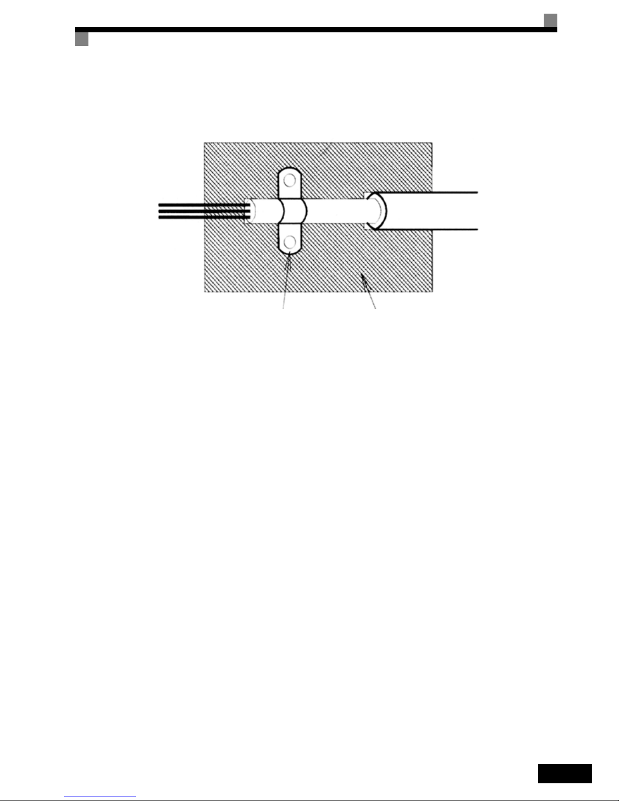
Shielded Cable:
– Use a cable with braided shield.
– Ground the maximum possible area of the shield. It is advisable to ground the shield by connecting the cable
to the ground plate with metal clips (see following figure).
Page 12
XI
The grounding surfaces must be highly conductive bare metal. Remove any coats of varnish and paint.
– Ground the cable shields at both ends.
– Ground the motor of the machine.
Further informations can be found in the document EZZ006543 which can be ordered at Omron Yaskawa
Motion Control.
Ground clip Ground plate
Page 13

XII
Line Filters
The IP54 version is already equipped with a internal EMC filter. For the IP00 and NEMA 1 / IP20 versions of
the Varispeed E7 the recommended line filters are as follows:
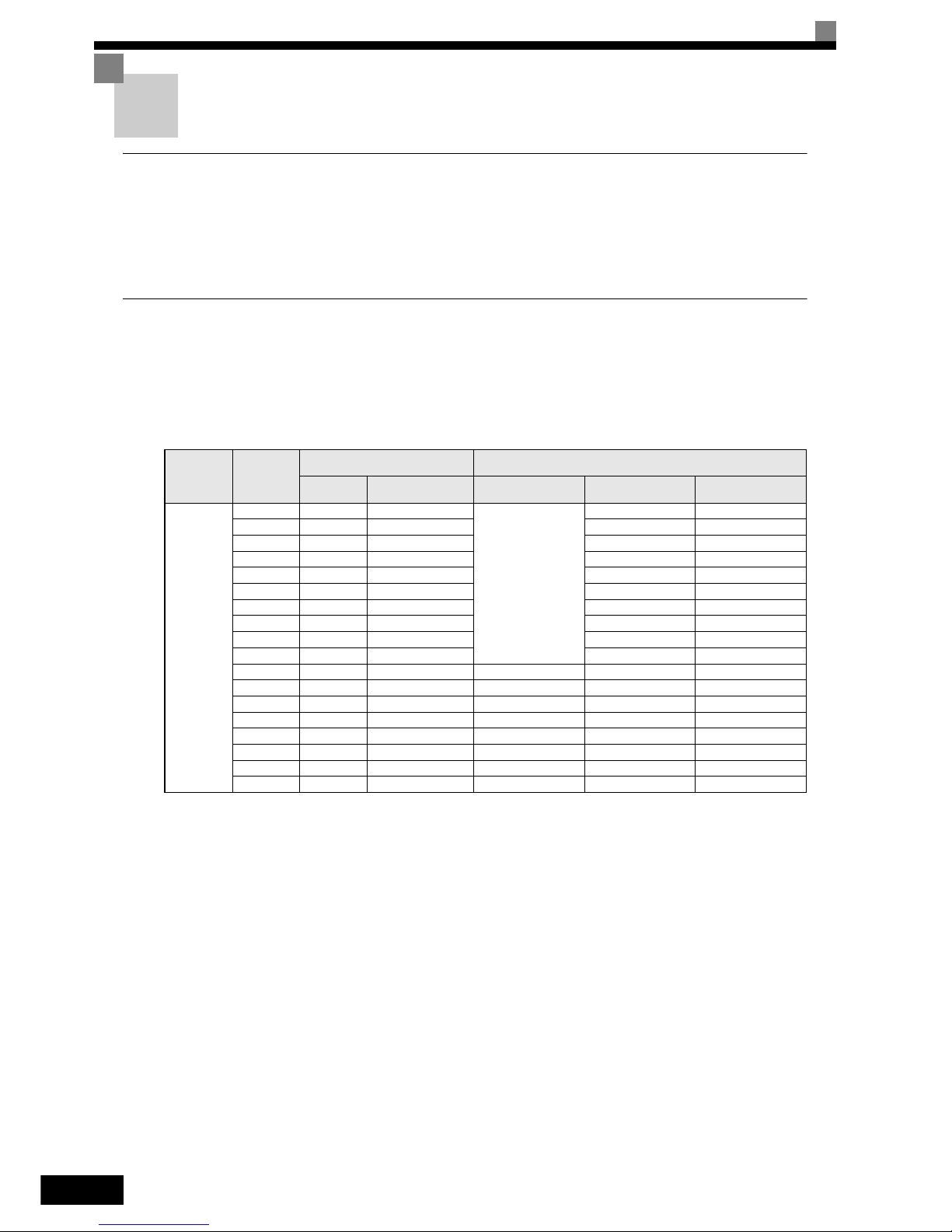
Recommended Line Filters for Varispeed E7 (IP00 and NEMA 1 / IP20)
Permissible emission of power drive systems for commercial and light environment (EN6 1800-3, A11)
(general availability, 1st environment)
Inverter Model Line Filter
Varispeed E7
(IP00/20)
Model
EN
55011 Clas s
Current
(A)
Weight
(kg)
Dimensions
W x D x H
CIMR-E7Z40P4
3G3RV-PFI3010-SE
B, 25 m
*1
*1. Class A, 100 m
10 1.1 141 x 46 x 330
CIMR-E7Z40P7
CIMR-E7Z41P5
CIMR-E7Z42P2
CIMR-E7Z43P7
3G3RV-PFI3018-SE 18 1.3 141 x 46 x 330CIMR-E7Z44P0
CIMR-E7Z45P5
CIMR-E7Z47P5
3G3RV-PFI3035-SE 35 2.1 206 x 50 x 355
CIMR-E7Z4011
CIMR-E7Z4015
3G3RV-PFI3060-SE 60 4.0 236 x 65 x 408
CIMR-E7Z4018
CIMR-E7Z4022
3G3RV-PFI3070-SE
A, 100 m
70 3.4 80 x 185 x 329
CIMR-E7Z4030
CIMR-E7Z4037
3G3RV- PFI3130-SE 130 4.7 90 x 180 x 366CIMR-E7Z4045
CIMR-E7Z4055
CIMR-E7Z4075 3G3RV- PFI3170-SE 170 6.0 120 x 170 x 451
CIMR-E7Z4090
3G3RV-PFI3200-SE 250 11 130 x 240 x 610
CIMR-E7Z4110
CIMR-E7Z4132
3G3RV-PFI3400-SE 400 18.5 300 x 160 x 610
CIMR-E7Z4160
CIMR-E7Z4185
3G3RV-PFI3600-SE 600 11,0 260 x 135 x 386
CIMR-E7Z4220
CIMR-E7Z4300 3G3RV-PFI3800-SE 800 31.0 300 x 160 x 716
Page 14

XIII
EMC Specifications of Varispeed E7 (IP54)
The Varispeed E7 IP54 is already equipped with an internal EMC filter. The Varispeed E7 IP54 complies with
EN55011 class A with a motor cable length up to 25m.
For the wiring methods to comply with the EMC regulations for t he Varispeed E7 (IP54) refer to page Chap-
ter 2, Wiring.
Inverter Model Line Filters
Varispeed E7
(IP00/20)
Type
EN
55011
Class
Current
(A)
Weight
(kg)
Dimensions
W x D x H
CIMR-E7Z20P4
3G3RV-PFI3010-SE
B, 25 m
*1
*1. Class A, 100 ambient temperature: 45°C max
10 1.1 141 x 45 x 330CIMR-E7Z20P7
CIMR-E7Z21P5
CIMR-E7Z22P2 3G3RV-PFI3018-SE 18 1.3 141 x 46 x 330
CIMR-E7Z23P7
3G3RV-PFI2035-SE 35 1.4 141 x 46 x 330
CIMR-E7Z25P5
CIMR-E7Z27P5
3G3RV-PFI2060-SE 60 3 206 x 60 x 355
CIMR-E7Z2011
CIMR-E7Z2015
3G3RV-PFI2100-SE 100 4.9 236 x 80 x 408
CIMR-E7Z2018
CIMR-E7Z2022
3G3RV-PFI2130-SE
A, 100 m
130 4.3 90 x 180 x 366
CIMR-E7Z2030
CIMR-E7Z2037 3G3RV-PFI2160-SE 160 6.0 120 x 170 x 451
CIMR-E7Z2045
3G3R V-PFI2200-SE 200 11.0 130 x 240 x 610
CIMR-E7Z2055
CIMR-E7Z2075
3G3R V-PFI3400-SE 400 18.5 300 x 160 x 564
CIMR-E7Z2090
CIMR-E7Z2110 3G3RV-PFI3600-SE 600 11.0 260 x 135 x 386
Page 15
XIV
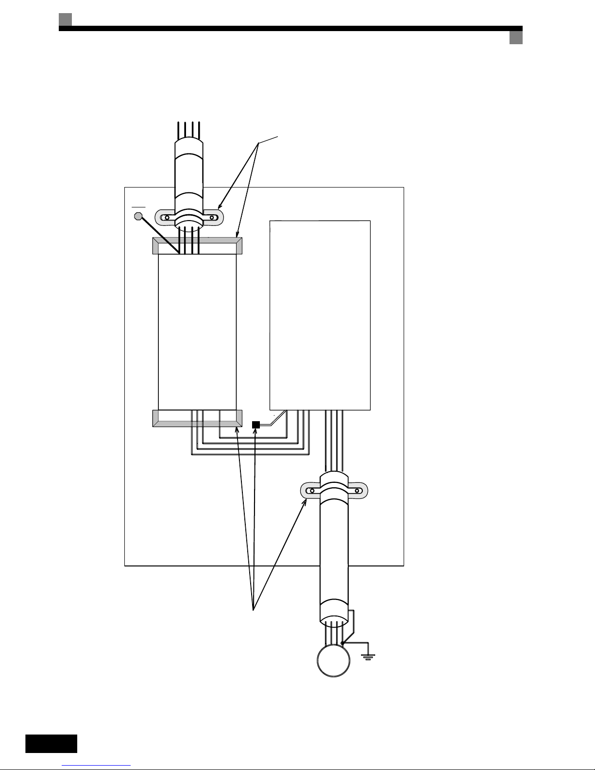
Installation inverters and EMC filters
L1 L3
L2
3~
M
U
PE
L1L2L3
V
W
PE
Filter
Inverter
Line
Load
Ground Bonds
( remove any paint )
Cable Length
as short as possible
Ground Bonds
( remove any paint )
Metal Plate
Motor cable
screened
PE
PE
Page 16

XV
Registered Trademarks
The following registered trademarks are used in this manual.
• DeviceNet is a registered trademark of the ODVA (Open DeviceNet Vendors Association, Inc.).
• InterBus is a registered trademark of Phoenix Contact Co.
• ControlNet is a registered trademark of ControlNet International, Ltd.
• LONworks is a registered trademark of the Echelon.
• Metasys is a registered trademark of Johnson Controls Inc.
• CANopen is a registered trademark of CAN in Automation e.V.
Page 17

XVI
Page 18

1
Handling Inverters
This chapter describes the checks required upon receiving or installing an Inverter.
Varispeed E7 Introduction..................................................1-2
Confirmations upon Delivery..............................................1-4
Exterior and Mounting Dimensions....................................1-9
Checking and Controlling the Installation Site .................1-13
Installation Orientation and Space...................................1-15
Accessing the Inverter Terminals.....................................1-16
Removing/Attaching the Digital Operator and Front Cover1-18
Page 19
1-2
Varispeed E7 Introduction
Varispeed E7 Applications
The Varispeed E7 is ideal for the following applications.
• Fan, blower and pump applications with variable torque characteristics.
Settings must be adjusted to the application for optimum operation. Refer to page 4-1, Trial Operation.
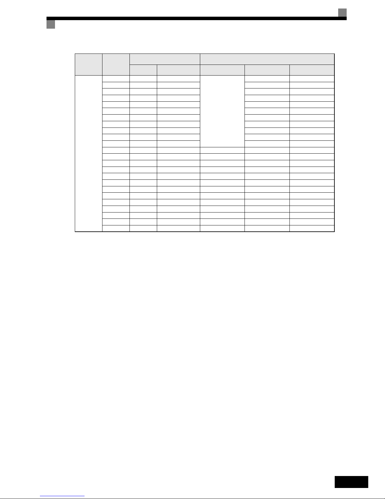
Varispeed E7 Models
The Varispeed E7 Series includes Inverters in two voltage classes: 200 V and 400 V. The maximum motor capacities
vary from 0.55 to 300 kW. The inverter is available in protection classes IP00, IP20 and IP54 according to the
following table:
Table 1.1 Varispeed E7 Models
Voltage Class
Maximum
Motor
Capacity
kW
Varispeed E7
Specifications
(Always specify through the protective structure when ordering.)
Output
Capacity kVA
Basic Model Number
IEC IP00
CIMR-E7Z
NEMA 1 (IEC IP20)
CIMR-E7Z
IEC IP54
CIMR-E7Z
200 V class
0.55 1.2 CIMR-E7Z20P4
Remove the top and bot-
tom covers from the IP20
model.
20P41 -
0.75 1.6 CIMR-E7Z20P7 20P71 -
1.5 2.7 CIMR-E7Z21P5 21P51 -
2.2 3.7 CIMR-E7Z22P2 22P21 -
3.7 5.7 CIMR-E7Z23P7 23P71 -
5.5 8.8 CIMR-E7Z25P5 25P51 -
7.5 12 CIMR-E7Z27P5 27P51 -
11 17 CIMR-E7Z2011 20111 -
15 22 CIMR-E7Z2015 20151 -
18.5 27 CIMR-E7Z2018 20181 -
22 32 CIMR-E7Z2022 20220 20221 -
30 44 CIMR-E7Z2030 20300 20301 -
37 55 CIMR-E7Z2037 20370 20371 -
45 69 CIMR-E7Z2045 20450 20451 -
55 82 CIMR-E7Z2055 20550 20551 -
75 110 CIMR-E7Z2075 20750 20751 -
90 130 CIMR-E7Z2090 20900 --
110 160 CIMR-E7Z2110 21100 --
Page 20
Varispeed E7 Introduction
1-3
400 V class
0.55 1.4 CIMR-E7Z40P4
Remove the top and bot-
tom covers from the IP20
model.
40P41 -
0.75 1.6 CIMR-E7Z40P7 40P71 -
1.5 2.8 CIMR-E7Z41P5 41P51 -
2.2 4.0 CIMR-E7Z42P2 42P21 -
3.7 5.8 CIMR-E7Z43P7 43P71 -
4.0 6.6 CIMR-E7Z44P0 44P01 -
5.5 9.5 CIMR-E7Z45P5 45P51 -
7.5 13 CIMR-E7Z47P5 47P51 47P52
11 18 CIMR-E7Z4011 40111 40112
15 24 CIMR-E7Z4015 40151 40152
18.5 30 CIMR-E7Z4018 40181 40182
22 34 CIMR-E7Z4022 40220 40221 40222
30 46 CIMR-E7Z4030 40300 40301 40302
37 57 CIMR-E7Z4037 40370 40371 40372
45 69 CIMR-E7Z4045 40450 40451 40452
55 85 CIMR-E7Z4055 40550 40551 40552
75 110 CIMR-E7Z4075 40750 40751 -
90 140 CIMR-E7Z4090 40900 40901 -
110 160 CIMR-E7Z4110 41100 41101 -
132 200 CIMR-E7Z4132 41320 41321 -
160 230 CIMR-E7Z4160 41600 41601 -
185 280 CIMR-E7Z4185 41850 -220 390 CIMR-E7Z4220 42200
--
300 510 CIMR-E7Z4300 43000 --
Voltage Class
Maximum
Motor
Capacity
kW
Varisp eed E7
Specifications
(Always specify through the protective structure when ordering.)
Output
Capacity kVA
Basic Model Number
IEC IP00
CIMR-E7Z
NEMA 1 (IEC IP20)
CIMR-E7Z
IEC IP54
CIMR-E7Z
Page 21
1-4
Confirmations upon Delivery
Checks
Check the following items as soon as the Inverter is delivered.
Additionally check that following parts are delivered in the package with the IP54 inverter:
If any irregularities in the above items are found, contact the agency from which the Inverter was purchased or
your Omron Ya skawa Motion Control representative immediately.
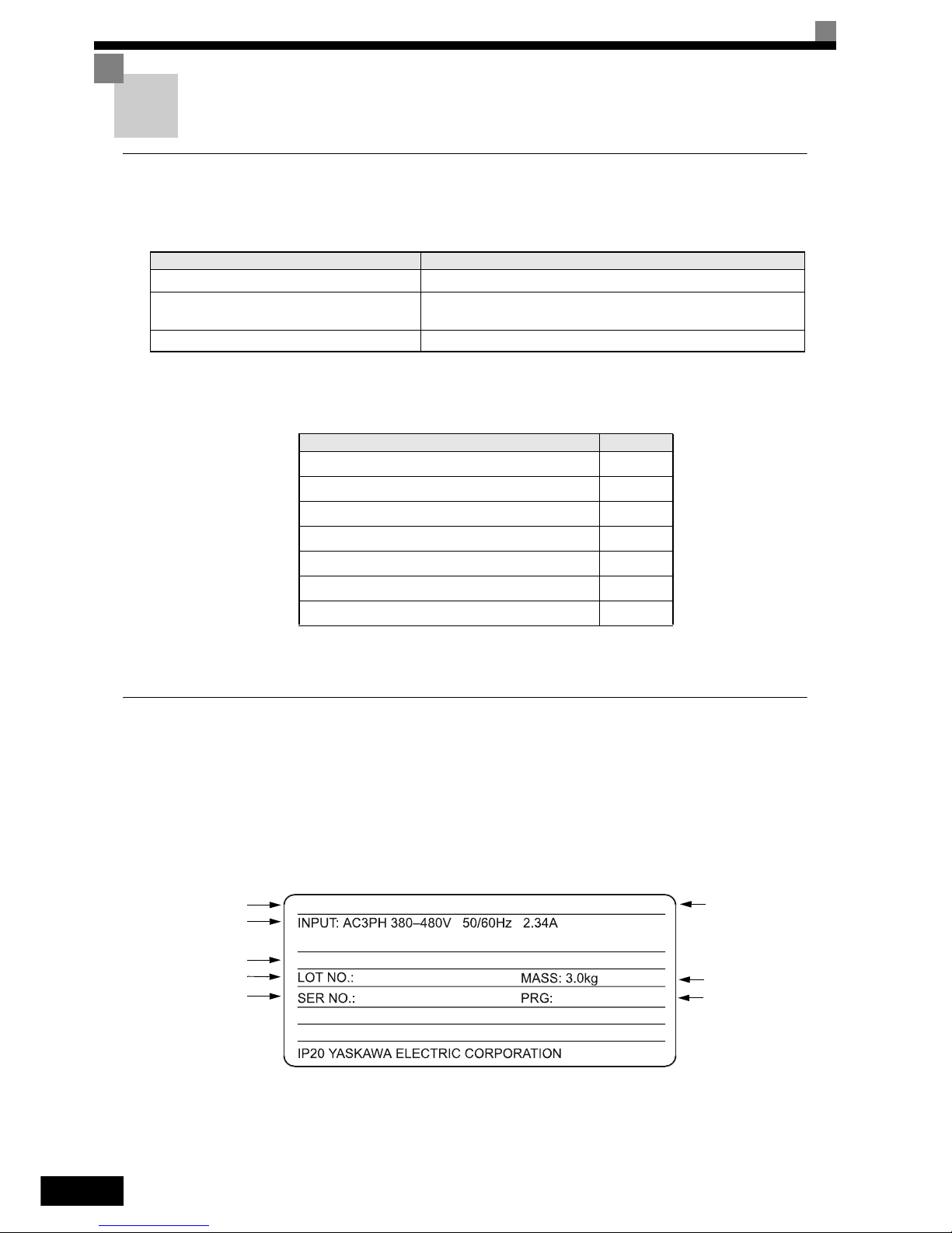
Nameplate Information
There is a nameplate attached to the side of each Inverter. The nameplate shows the model number, specifications, lot number, serial number, and other information on the Inverter.
Example Nameplate
The following nameplate is an example for a standard European Inverter: 3-phase, 400 VAC, 0.55 kW,
NEMA 1 / IP20 standards
Fig 1.1 Nameplate Example
Table 1.2 Checks upon delivery
Item Method
Has the correct Inverter model been delivered? Check the model number on the nameplate on the side of the Inverter.
Is the Inverter damaged in any way?
Inspect the entire exterior of the Inverter to see if there are any
scratches or other damage resulting from shipping.
Are any screws or other components loose? Use a screwdriver or other tools to check for tightness.
Table 1.3 Additional Deliveries with IP54 Inverters
Part Name Qty.
Cable Gland (for Input) 1
Cable Gland (for Motor Output) 1
Cable Gland (for Control) 1
Cable Gland (for Fieldbus) 1
Door Key 1
Blind Plug (Control Cable Entry) 1
Blind Plug (Fieldbus Cable Entry) 1
OUTPUT: AC3PH 0-480V 0-200Hz 1.8A 1.4kVA
MODEL: CIMR-E7Z40P4
SPEC: 40P41A
Inverter model
Input specifications
Output specifications
Lot number
Serial number
Inverter
specifications
Mass
Software Number
Page 22
Confirmations upon Delivery
1-5
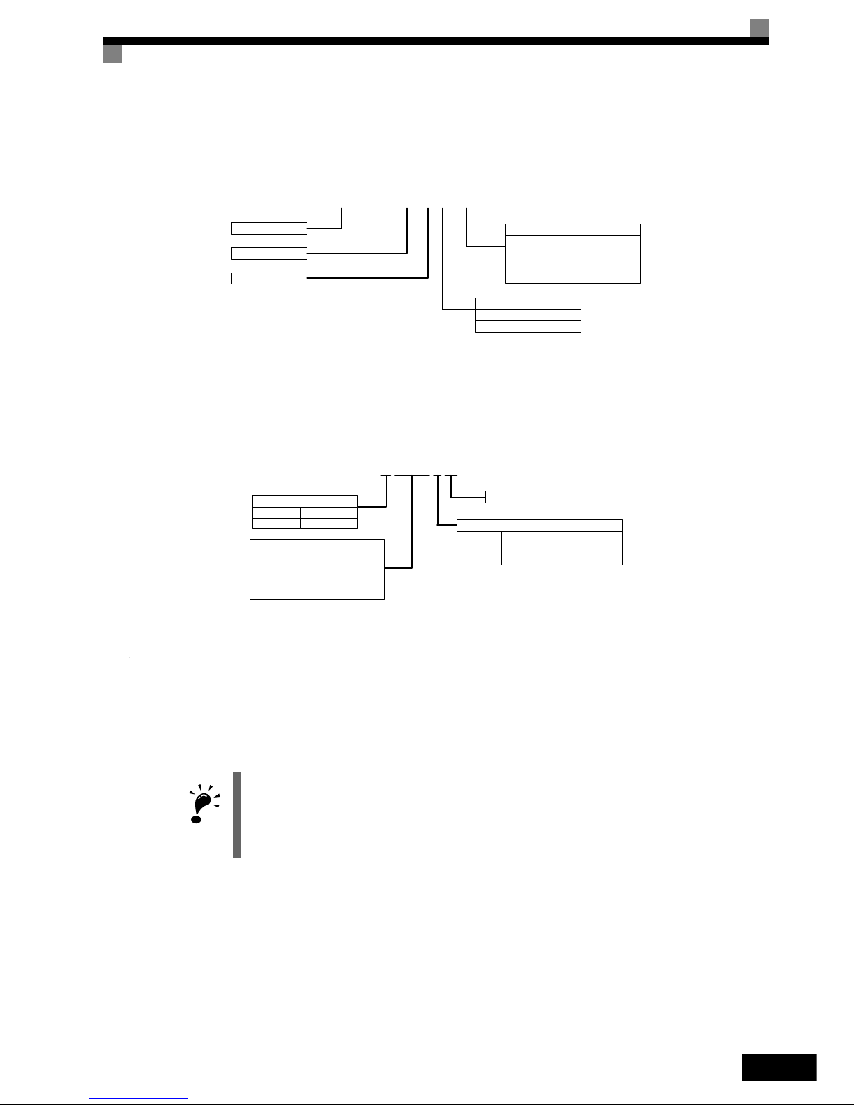
Inverter Model Numbers
The model number of the Inverter on the nameplate indicates the specification, voltage class, and maximum
motor capacity of the Inverter in alphanumeric codes.
Fig 1.2 Inverter Model Numbers
Inverter Specifications
The Inverter specifications (“SPEC”) on the nameplate indicate the voltage class, maximum motor capacity,
the protective structure, and the revision of the Inverter in alphanumeric codes.
Fig 1.3 Inverter Specifications
Inverter Software Version
The Inverter software version can be read out from the monitor parameter U1-14. The parameter shows the
last four digits of the software number (e.g. display is “3021” for the software version VSE103021).
IMPORTAN
T
This manual describes the functionality of the inverter software version VSE103021.
Older software versions do not support all described functions. Check the software versions before
starting to work with this manual.
CIMR – E7Z40P4
Inverter
Varispeed E7
European Spec.
Max. Motor Power
0P4 0.55 kW
0P7 0.75 kW
to to
300 300 kW
Voltage Class
2 200 V
4 400 V
40P41A
Revision
Protection
0 IP00
1 IP20
2 IP54
Voltage Class
2 200 V
4 400 V
Max. Motor Power
0P4 0.55 kW
0P7 0.75 kW
to to
300 300 kW
Page 23

1-6
Component Names
Inverters of 18.5 kW or Less
The external appearance and component names of the Inverter are shown in Fig 1.4, the terminal arrangement
in Fig 1.5
Fig 1.4 NEMA 1 Inverter Appearance (18.5 kW or Less)
Fig 1.5 Terminal Arrangement (18.5 kW or less)
IMPORTANT
The top cover is a protection against foreign bodies (screws, metal scrap from drilling etc.), which could fall
into the inverter during the installation in the cabinet.
Remove the top cover when the installation is finished!
Top cover
Front cover
Digital Operator
Terminal cover
Bottom protective cover
Diecast case
Nameplate
Mounting hole
AC
AC
S6
-V
AM
R+M5RPAC
S1 S4SPS7 M4
+V
S3
SCIGA2
M2
SN M6
FM
A1
E(G)
E(G)
MCMB
S5 M1
MP
MA
M3S2
S+
R-
S-
NOTUSED
Control Circuit Terminals
Main Circuit Terminals
Charge Indicator
Ground Terminal
Page 24
Confirmations upon Delivery
1-7
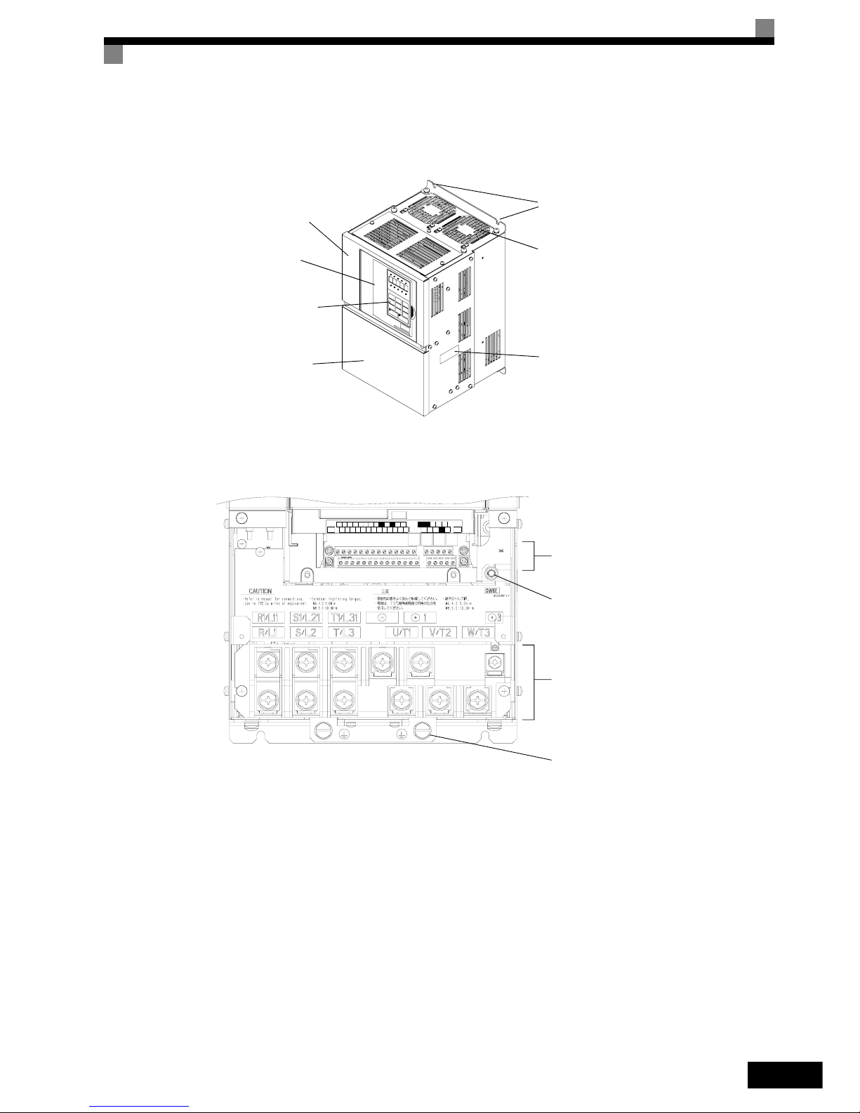
Inverters of 22 kW or More
The external appearance and component names of the Inverter are shown in Fig 1.6, the terminal arrangement
in Fig 1.7
Fig 1.6 Inverter Appearance (22 kW or More)
Fig 1.7 Terminal Arrangement (22kW or More)
Mounting holes
Cooling fan
Nameplate
Inverter cover
Front cover
Digital Operator
Terminal cover
AC
ACS6-VAM
R+M5RPAC
S1 S4SPS7 M4
+VS3SCIGA2M2SN
M6
FM
A1
E(G)
E(G)
MCMB
S5 M1
MP
MA
M3S2 S+
R-
S-
Control Circuit Terminals
Carge Indicator
Main Circuit Terminals
Ground Terminals
Page 25
1-8
Protection Class IP54
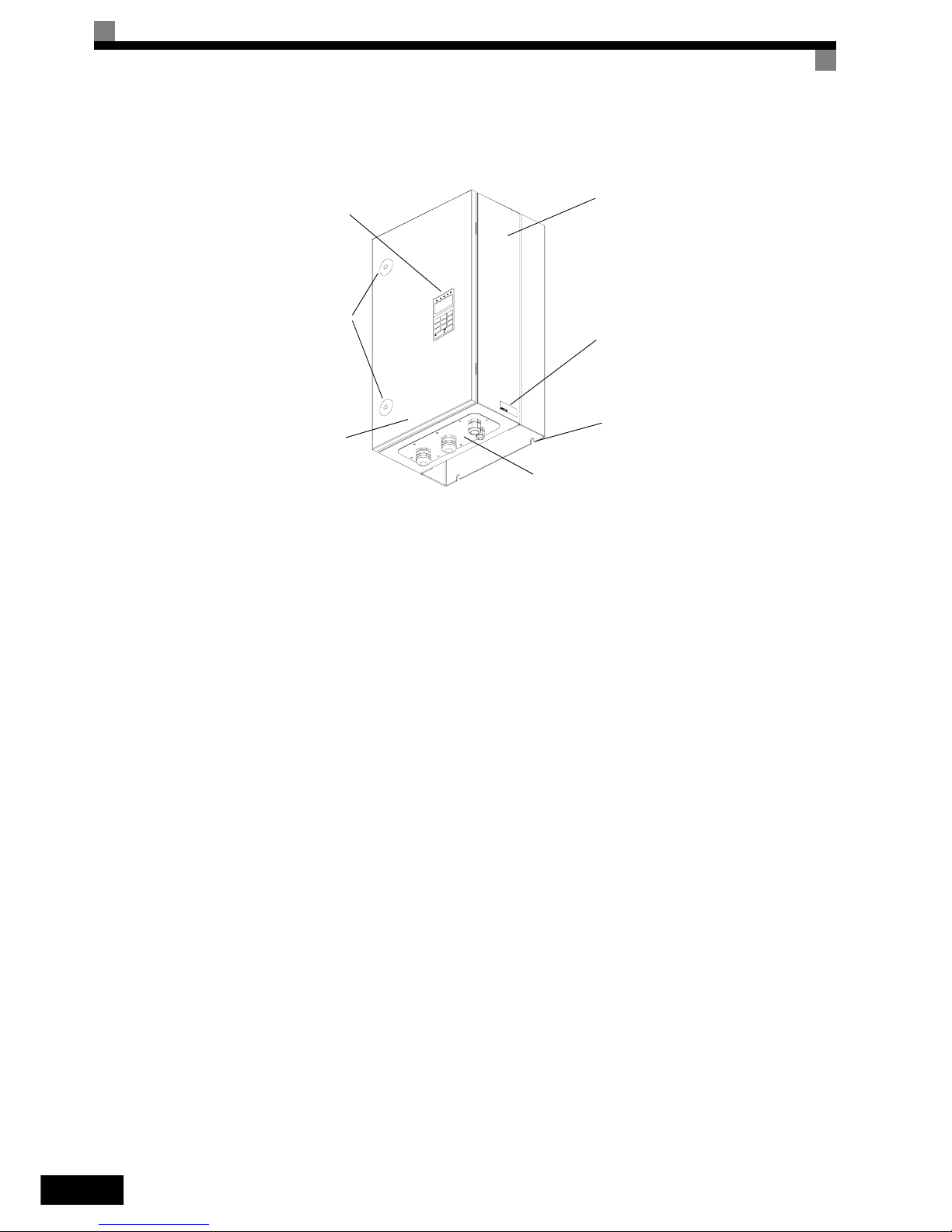
The external appearance and component names of the Inverter are shown in Fig 1.8.
Fig 1.8 IP54 Inverter Appearance
Nameplate
Inverter enclosure
Mounting Holes
Cable Entry Plate
Digital Operator
Door Locks
Door
Page 26
Exterior and Mounting Dimensions
1-9
Exterior and Mounting Dimensions
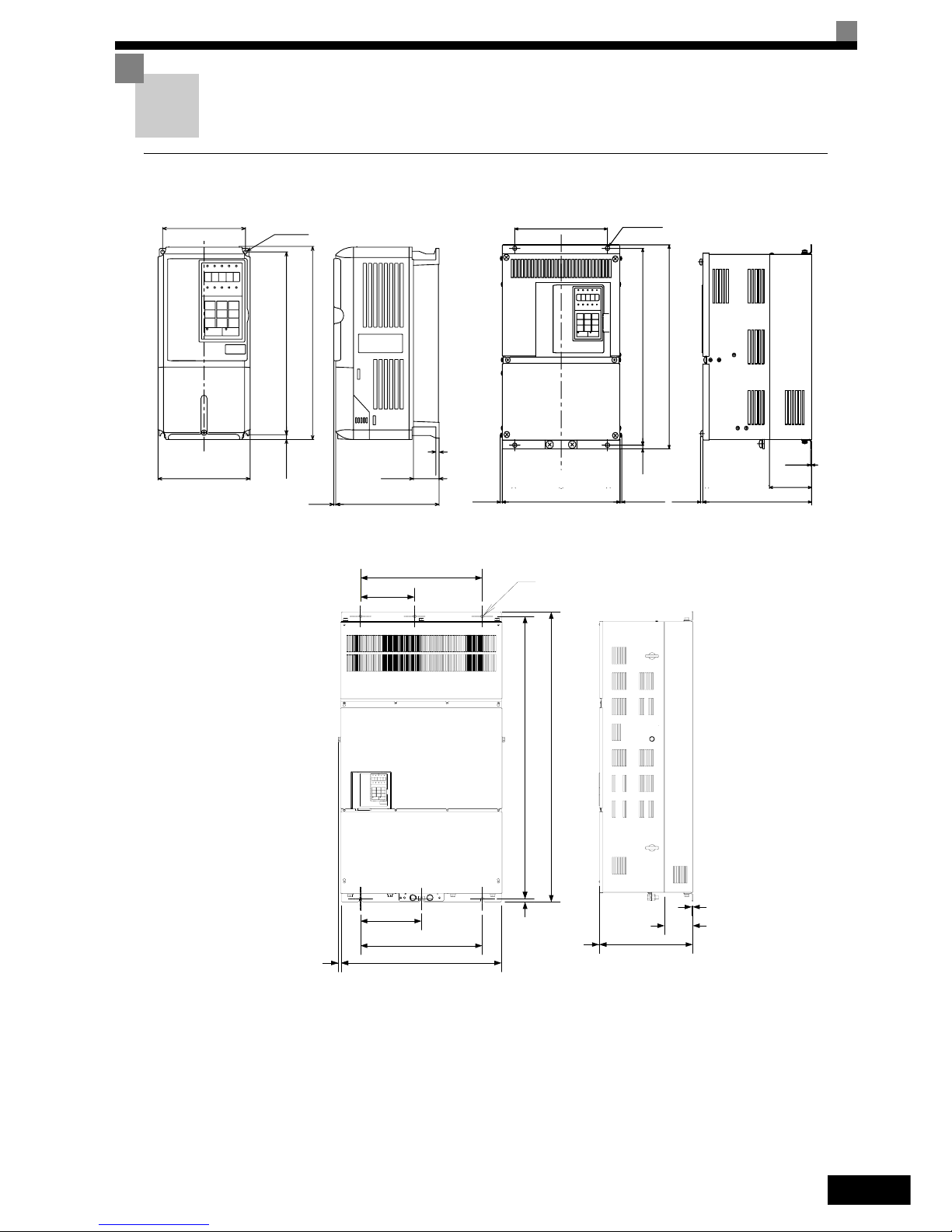
IP00 Inverters
Fig 1.9 Exterior Diagrams of IP00 Inverters
W
W1
3
H1H2DH
D1
4-d
t1
W
W1
4-d
H2
5
D1
D
H1
H
t1
Max.10
Max.10
W2
W1
Ø
W1
W3
W
15
H1
H
H2
D1
D
t1
5
200 V Class Inverters of 22 or 110 kW
400 V Class Inverters of 22 to 160 kW
200 V/400 V Class Inverters of 0.55 to 18.5 kW
400 V Class Inverters of 185 to 300 kW
Page 27
1-10
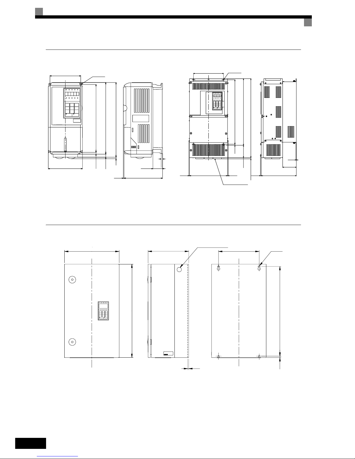
NEMA 1 / IP20 Inverters
Fig 1.10 Exterior Diagrams of NEMA 1 / IP20 Inverters
IP54 Inverters
Fig 1.11 Exterior Diagrams of IP54 Inverters
W
W1
3
H1H2DH0
D1
H3
4 H
4-d
t1
W
W1
H3
H0
H1
H2
D1
D5
4-d
t1
Max.10
H
Grommet
Max.10
Max.10
200 V Class Inverters of 22 to 75 kW
400 V Class Inverters of 22 to 160 kW
200 V/400 V Class Inverters of 0.55 to 18.5 kW
WW1
H
H1H2
t1
D
4-d
2 - lifting holes
Page 28
Exterior and Mounting Dimensions
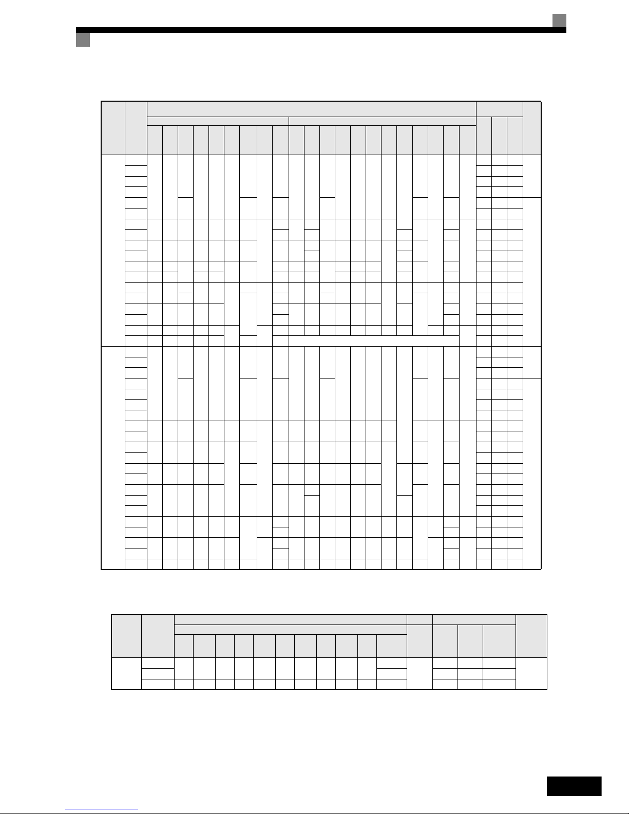
1-11
Table 1.4 Inverter Dimensions (mm) and Masses (k g) from 0.4 to 160 kW, IP00 and NEMA 1 / IP20
Table 1.5 Inverter Dimensions (mm) and Masses (kg) of 400V Class Inverters of 185 kW to 300 kW, IP00
Voltage
Class
Max.
Appli-
cable
Motor
Output
[kW]
Dimensions (mm)
Caloric Value
(W)
Cool-
ing
Metho
d
Protection Class IP00 Protection Class NEMA 1 / IP20
Exter
nal
Inter-
nal
Total
Heat
Gen-
eration
W H D W1 H1 H2 D1 t1
Appr
ox.
Mass
W H D W1 H0 H1 H2 H3 D1 t1
Appr
ox.
Mass
Moun
ting
Holes
d*
200 V
(3-
phase)
0.55
140 280
157
126 266 7
39
5
3
140 280
157
126 280 266 7
0
39
5
3
M5
20 39 59
Natu-
ral
0.75 27 42 69
1.5 50 50 100
2.2 70 59 129
3.7
177 59 4 177 59 4
112 74 186
Fan
5.5 164 84 248
7.5
200 300 197 186 285 7.5 65.5
2.3
6
200
300
197 186 300 285 8 65.5
2.3
6
M6
219 113 332
11 7 310 10 7 374 170 544
15
240 350 207 216 335 8 78 11 240
350
207 216 350 335
7.5
0
78 11
429 183 612
18.5 380 30 501 211 712
22 250 400
258
195 385
7.5 100
21 254 535
258
195 400 385 135
100
24 586 274 860
30 275 450 220 435 24 279 615 220 450 435 165 27 865 352 1217
37
375 600
298
250 575
12.5
100
3.2
57
380 809
298
250 600 575
12.5
209
100
3.2
62
M10
1015 411 1426
45 328
130
63 328
130
68 1266 505 1771
55
450 725 348 325 700
86
453 1027 348 325 725 700 302
94 1588 619 2207
75 87 95 2019 838 2857
90 500 850 358 370 820
15 4.5
108 504 1243 358 370 850 820 15 390 4.5 114
M12
2437 997 3434
110 575 885 378 445 855 140 150 --- 2733 1242 3975
400 V
(3-
phase)
0.55
140 280
157
126 266 7
39
5
3
140 280
157
126 266 266 7
0
39
5
3
M5
14 39 53
Natu-
ral
0.75 17 41 58
1.5 36 48 84
2.2
177 59 4 177 59 4
59 56 115
Fan
3.7 80 68 148
4.0 91 70 161
5.5 127 82 209
7.5
200 300 197 186 285 8 65.5
2.3
6 200 300 197 186 300 285 8 65.5
2.3
6
M6
193 114 307
11 252 158 410
15
240 350 207 216 335
7.5
78 10 240 350 207 216 350 335
7.5
78 10
326 172 498
18.5 426 208 634
22
279 450 258 220 435 100 21 279 535 258 220 450 435
85
100 24
466 259 725
30 678 317 995
37
325 550 283 260 535 105 36 329
635
283 260 550 535 105 40
784 360 1144
45
715 165
901 415 1316
55 1203 495 1698
75
450 725 348 325 700 12.5
130
3.2
88
453 1027 348 325 725 700 12.5 302
130
3.2
96
M10
1399 575 1974
90 89 97 1614 671 2285
110
500 850 358 370 820 15
4.5
102
504 1243 358 370 850 820 15 393
4.5
122
M12
2097 853 2950
132 120 130 2388 1002 3390
160 575 916 378 445 855 45.8 140 160 579 1324 378 445 916 855 46 408 140 170 2791 1147 3938
Voltage
Class
Max.
Applica-
ble Motor
Output
[kW]
Dimensions (mm) Caloric Value (W)
Cooling
Method
Protection Class IP00
Mount-
ing
Holes d
Exter-
nal
Internal
Total
Heat
Genera-
tion
W H D W1 W2 W3 H1 H2 D1 t1
Approx.
Mass
400V
(3-phase)
185
710 1305 413 540 240 270 1270 15 125.5 4.5
260
M12
3237 1372 4609
Fan220 280 3740 1537 5277
300 916 1475 413 730 365 365 1440 15 125.5 4.5 405 5838 2320 8158
Page 29

1-12
Table 1.6 Inverter Dimensions (mm) and Masses (kg) of 400V class inverters 7.5 to 55 kW, IP54
Voltage
Class
Max.
Applica-
ble Motor
Output
[kW]
Dimensions (mm)
Cooling
Method
W H D W1 H1 H2 t1
Approx.
Mass
Mount-
ing
Holes d
Total
Heat
Genera-
tion
400V
(3-phase)
7.5
350 600
240
260 576 9 2.5
25
∅ 10
M8
302
Fan
11 423
15
260 30
531
18.5 655
22
410 650 300 270 620 12 2.5 43
∅ 12
M10
754
30 989
37
580 750 330 410 714 11 2.5 71
∅ 14
M10
1145
45 1317
55 1701
Page 30

Checking and Controlling the Installation Site
1-13
Checking and Controlling the Installation Site
Install the Inverter in the installation site described below and maintain optimum conditions.
Installation Site
Install the Inverter under the following conditions in a pollution degree 2 environment.
Protection covers are attached to the top and bottom of the NEMA 1 and IP00 Inverters. Be sure to remove the
top cover before operating a 200 or 400 V Class Inverter with an output of 18.5 kW or less inside a panel.
• Observe the following precautions when mounting the Inverter.
• Install the Inverter in a clean location which is free from oil mist and dust. It can be installed in a totally
enclosed panel that is completely shielded from floating dust.
• When installing or operating the Inverter, always take special care so that metal powder, oil, water, or
other foreign matter does enter the Inverter.
• Do not install the Inverter on combustible material, such as wood.
• Install the Inverter in a location free from radioactive materials and combustible materials.
• Install the Inverter in a location free from harmful gasses and liquids.
• Install the Inverter in a location without excessive oscillation.
• Install the Inverter in a location free from chlorides.
• Install the Inverter in a location without in direct sunlight.
• The IP54 Inverters provide protection from non-conductive dust and splashing water from all directions.
Install the Inverter indoors in a heated and controlled environment to avoid condensation inside the
Inverter.
• Keep any water or dust outside of the IP54 Inverter when wiring.
Controlling the Ambient Temperature
To enhance the reliability of operation, the Inverter should be installed in an environment free from extreme
temperature increases. If the IP00 or NEMA 1 Inverter is installed in an enclosed environment, such as a box,
use a cooling fan or air conditioner to maintain the internal air temperature below 45°C.
When the IP54 Inverter is installed in a environment with low temperatures or when the Invert er remains
switched off for a long time, condensation may occur inside the Inverter. In that case additional heaters may
effectively prevent condensation inside the inverter.
Protecting the IP00 or NEMA 1 Inverter from Foreign Matter
Place a cover over the Inverter during installation to shield it from metal power produced by drilling.
Always remove the cover from the Inverter after completing installation. Otherwise, ventilation will be
reduced, causing the Inverter to overheat.
Type Ambient Operating Temperature Humidity
Protection Class IP20 and IP54 -10 to + 40 °C 95% RH or less (no condensation)
Protection Class IP00 -10 to + 45 °C 95% RH or less (no condensation)
Page 31

1-14
Additional Installation Precautions for the IP54 Inverters
• Ensure that the door locks are closed before carrying the Inverter. Always hold the case when carrying the
Inverter, do not carry it holding the door or the cable glands. If the door locks are open or the Inverter is
held by the door (or cable glands) when carrying the main body of the Inverter may fall, possibly resulting
injury.
• Pay attention not to damage the cable glands when lifting. Otherwise the equip ment may be damaged by
ingress of water or dust.
Keeping the IP54 protection
• Mount the blind plugs attached for option and control entry if these terminals are not connected
• Pay attention not to damage the cable glands during the installation
Page 32

Installation Orientation and Space
1-15
Installation Orientation and Space
Install the Inverter vertically so as not to reduce the cooling effect. When installing the Inverter, always provide the following installation space to allow normal heat dissipation.
Fig 1.12 Inverter Installation Orientation and Space
IMPORTANT
1. The same space is required horizontally and vertically for Inverters of all protection classes, either
IP00, NEMA 1 / IP20 and IP54 Inverters.
2. Always remove the top cover after installing a 200 or 400 V Class Inverter with an output of 18.5 kW
or less in a panel.
3. Always provide enough space for suspension eye bolts and the main circuit lines when installing a
200 or 400 V Class Inverter with an output of 22 kW or more in a panel.
4. When IP54 Inverters are installed side by side provide a distance of 60mm or more between the
Inverters
30mm min.
30mm min.
A
50mm
min.
Horizontal Space
B
120mm min.
Air
Air
Vertical Space
A B
200V class inverter, 0.55 to 90 kW
400V class inverter, 0.55 to 132 kW
50 mm 120 mm
200V class inverter, 110 kW
400V class inverter, 160 to 220 kW
120 mm 120 mm
400V class inverter, 300 kW 300 mm 300 mm
Page 33

1-16
Accessing the Inverter Terminals
Removing the Terminal Cover (IP00 and NEMA 1 / IP20 Inverters)
Inverters of 18.5 kW or Less
Loosen the screw at the bottom of the terminal cover, press in on the sides of the terminal cover in the directions of arrows 1, and then lift up on the terminal in the direction of arrow 2.
Fig 1.13 Removing the Terminal Cover (Model CIMR-E7Z25P51 Shown Above)
Inverters of 22 kW or More
Loosen the screws on the left and right at the top of the terminal cover, pull out the terminal cover in the direction of arrow 1 and then lift up on the terminal in the direction of arrow 2.
Fig 1.14 Removing the Terminal Cover (Model CIMR-E7Z20220 Shown Above)
Attaching the Terminal Cover
When wiring the terminal block has been completed, attach the terminal cover by reversing the removal procedure.
For Inverters with an output of 18.5 kW or less, insert the tab on the top of the terminal cover into th e groove
on the Inverter and press in on the bottom of the terminal cover until it clicks into place.
1
2
1
1
2
Page 34

Accessing the Inverter Terminals
1-17
Opening the Door (IP54 Inverters)
Unlock the door locks with the provided key by pushing and rotating it 90 degrees in the directions of arrow 1
and open the door in the direction of arrow 2.
When opening the door, always take special care so that powder, oil, water or other foreign materials do not
enter the Inverter.
Fig 1.15 Opening the door on a IP54 inverter
Closing the Door (IP54 Inverters)
Close and lock the door tightly by reversing the opening procedure.
IMPORTANT
Max. permitted door opening angle is approx. 135 degrees.
Opening the door over 135 degrees may damage the door hinges.
If the inverter is put into horizontal orientation for wiring or maintenance, the door should be supported
and operation should be finished quickly to avoid stress to the door hinges.
1
1
2
OPEN
CLOSE
Page 35

1-18
Removing/Attaching the Digital Operator and
Front Cover
The digital operator can only be removed on Inverters in protection class IP00 and NEMA 1 / IP20
Inverters of 18.5 kW or Less
To attach optional cards or change the terminal board, remove the Digital Operator and front cover in addition
to the terminal cover. Always remove the Digital Operator from the front cover before removing the front
cover itself.
The removal and attachment procedures are described below.
Removing the Digital Operator
Press the lever on the side of the Digital Operator in the direction of arrow 1 to unlock the Digital Operator
and lift the Digital Operator in the direction of arrow 2 to remove the Digital Operator as shown in the following illustration.
Fig 1.16 Removing the Digital Operator (Model CIMR-E7Z45P5 Shown Above)
1
2
Page 36

Removing/Attaching the Digital Operator and Front Cover
1-19
Removing the Front Cover
Press the left and right sides of the front cover in the directions of arrows 1 and lift the bottom of the cover in
the direction of arrow 2 to remove the front cover as shown in the following illustration.
Fig 1.17 Removing the Front Cover (Model CIMR-E7Z45P5 Shown Above)
Mounting the Front Cover
After wiring the terminals, mount the front cover to the Inverter by performing the steps to remove the front
cover in reverse order.
1. Do not mount the front cover with the Digital Operator attached to the front cover; otherwise, Digital
Operator may malfunction due to imperfect contact.
1. Insert the tab of the upper part of the front cover into the groove of the Inverter and press the lower part of
the front cover onto the Inverter until the front cover snaps shut.
Mounting the Digital Operator
After attaching the terminal cover, mount the Digital Operator onto the Inverter using the following procedure.
1. Hook the Digital Operator at A (two locations) on th e front cover in the direction of arrow 1 as shown in
the following illustration.
1. Press the Digital Operator in the direction of arrow 2 until it snaps in place at B (two locations).
Fig 1.18 Mounting the Digital Operator
1
2
A
B
Page 37

1-20
Inverters of 22 kW or More
For inverters with an output of 22 kW or more, remove the terminal cover and then use the following procedures to remove the Digital Operator and front cover.
Removing the Digital Operator
Use the same procedure as for Inverters with an output of 18.5 kW or less.
Removing the Front Cover
Lift up at the location label 1 at the top of the control circuit terminal card in the direction of arrow 2.
Fig 1.19 Removing the Front Cover (Model CIMR-E7Z2022 Shown Above)
Attaching the Front Cover
After completing required work, such as mounting an optional card or setting the terminal card, attach the
front cover by reversing the procedure to remove it.
1. Confirm that the Digital Operator is not mounted on the front cover. Contact faults can occur if the cover is
attached while the Digital Operator is mounted to it.
2. Insert the tab on the top of the front cover into the slot on the Inverter and press in on the cover until it
clicks into place on the Inverter.
Attaching the Digital Operator
Use the same procedure as for Inverters with an output of 18.5 kW or less.
IMPORTANT
1. Do not remove or attach the Digital Operator or mount or remove the front cover using methods other
than those described above, otherwise the Inverter may break or malfunction due to imperfect contact.
2. Never attach the front cover to the Inverter with the Digital Operator attached to the front cover. Imperfect
contact can result.
Always attach the front cover to the Inverter by itself first, and then attach the Digital Operator to the front
cover.
1
2
Page 38

2
Wiring
This chapter describes wiring terminals, main circuit termin al co nn ections, main circuit terminal
wiring specifications, control circuit terminals, and control circuit wiring specifications.
Connection Diagrams ........................................................2-2
Terminal Block Configuration.............................................2-5
Wiring Main Circuit Terminals............................................2-7
Wiring Control Circuit Terminals......................................2-27
Wiring Check....................................................................2-37
Installing and Wiring Option Cards ..................................2-38
Page 39

2-2
Connection Diagrams
The connection diagrams of the Inverters are shown in Fig 2.1 and Fig 2.2
When using the Digital Operator, the motor can be operated by wiring only the main circuits.
Fig 2.1 Connection Diagram of IP20 Inverters (Model CIMR-E7Z47P51 Shown Above)
M2
M1
MC
MB
MA
L1
L2
L3
PE
M
R/L1
S/L2
T/L3
U/T1
V/T2
W/T3
E(G)
1 2
UX
Motor
1
2
Line
Filter
Main
contactor
3-phase power
supply
380 to 480 V
50/60 Hz
DC reactor to improve input
power factor (optional)
Short-circuit bar
M4
M3
Fault contact output
250 VAC, 1 A max.
30 VDC, 1 A max.
Contact output 1
[Default: During run]
Contact output 2
[Default: Zero speed]
Multi-function digital
output
250 VAC, 1 A max.
30 VDC, 1 A max.
Fuse
Shield
terminal
Varispeed E7
CIMR-
E7Z47P51
S2
S3
S4
S5
S6
S7
SN
SC
SP
24V
+V
AC
A2
A1
0V
E(G)
PP
4 to 20mA
0 to 10V
3
2k
2
1
-V
Ω
2k
Ω
Reverse Run/Stop
External faul t
Fault reset
Multi-step speed setting 1
Multi-step speed setting 2
Jog frequency selection
Multi-function
digital inputs
[Factory se ttin gs]
Analog input 1: Master
frequency reference
0 to 10 V (20 k )
Analog input power supply
+15 V, 20 mA
Multi-function analog input 1:
[Default: Frequency Bias
4 to 20 mA (250 )]ΩΩ
Analog input power supply
-15 V, 20 mA
Shield
terminal
Adjustment
Forward Run/Stop S1
FM
+
-
AC
FM
Multi-function analog output 1
(0 to 10 V, 2 mA)
[Default: Output frequency, 0 to 10 V]
Multi-function analog output 2
(0 to 10 V, 2 mA)
[Default: Output power, 0 to 10 V]
Ω
Adjustment,
20 k
Ω
+
-
AM
AM
P
Shielded wires
Twisted-pair
shielded wire s
Input Option Cards
2CN
R+
R-
S+
S-
IG
P
P
Terminating
resistance
MEMOBUS
communication
RS-485/422
3
Adjustment,
20 k
Page 40

Connection Diagrams
2-3
Fig 2.2 Connection Diagram of IP54 Inverters (Model CIMR-E7Z47P52 Shown Above)
M2
M1
MC
MB
MA
L1
L2
L3
PE
M
R/L1
S/L2
T/L3
U/T1
V/T2
W/T3
E(G)
1 2
UX
Motor
1
2
Main
contactor
3-phase power
supply
380 to 480 V
50/60 Hz
DC reactor to improve input
power factor (optional)
Short-circuit bar
M4
M3
Fault contact output
250 VAC, 1 A max.
30 VDC, 1 A max.
Contact output 1
[Default: During run]
Contact output 2
[Default: Zero speed]
Multi-function digital
output
250 VAC, 1 A max.
30 VDC, 1 A max.
Fuse
Shield
terminal
Varispeed E7
S2
S3
S4
S5
S6
S7
SN
SC
SP
24V
+V
AC
A2
A1
0V
E(G)
PP
4 to 20mA
0 to 10V
3
2k
2
1
-V
Ω
2k
Ω
Reverse Run/Stop
External fault
Fault reset
Multi-step speed setting 1
Multi-step speed setting 2
Jog frequency selection
Multi-function
digital inputs
[Factory settings]
Analog input 1: Master
frequency reference
0 to 10 V (20 k )
Analog input power supply
+15 V, 20 mA
Multi-function analog input 1:
[Default: Frequency Bias
4 to 20 mA (250 )]ΩΩ
Analog input power supply
-15 V, 20 mA
Shield
terminal
Adjustment
Forward Run/Stop S1
FM
+
-
AC
FM
Multi-function analog output 1
(0 to 10 V, 2 mA)
[Default: Output frequency, 0 to 10 V]
Multi-function analog output 2
(0 to 10 V, 2 mA)
[Default: Output power, 0 to 10 V]
Ω
Adjustment,
20 k
Ω
+
-
AM
AM
P
Shielded wires
Twisted-pair
shielded wires
Input Option Cards
2CN
R+
R-
S+
S-
IG
P
P
Terminating
resistance
MEMOBUS
communication
RS-485/422
3
Adjustment,
20 k
CIMR-E7Z47P52
Page 41

2-4
Circuit Descriptions
Refer to the numbers indicated in Fig 2.1 and Fig 2.2.
1 These circuits are hazardous and are separated from accessible surfaces by protective separation.
2 These circuits are separated from all other circuits by protective separation consisting of double and
reinforced insulation. These circuits may be interconnected with SELV (or equivalent) or nonSELV
*
circuits, but not both.
3 Inverter supplied by four-wire-system source (neutral grounded)
These circuits are SELV
*
circuits and are separated from all other circuits by protective separation
consisting of double and reinforced insulation. These circuits may only be interconnected with
other SELV
*
(or equivalent) circuits.
Inverter supplied by three-wire-system source (ungrounded or corner grounded)
These circuits are not separated from hazardous circuits by protective separation, but only with
basic insulation. These circuits must not be interconnected with any circuits which are accessible,
unless they are isolated from accessible circuits by supplemental insulation.
* SELV (Safety Extra Low Voltage) circuits have no direct connection to the primary power and are supplied
by a transformer or equivalent isolating device. The circuits are designed and protected, so that, under normal
and fault condition, its voltage does not exceed a safe value. (See IEC 61010)
IMPORTANT
1. Control circuit terminals are arranged as shown below.
2. The output current capability of the +V terminal is 20 mA.
3. Main circ uit terminals are indicated with double circles and control circuit terminals are indicated with single circles.
4. The wiring of the digital inputs S1 to S7 is shown for the connection of relay contacts or NPN transistors (0V common and sinking mode). This is the default setting.
For the connection of PNP transistors or for using a 24V external power supply, refer to page 2-33, Sinking/Sourc-
ing Mode.
5. The master speed fre quency reference can be input either at terminal A1 or at terminal A2 by changing the setting
of parameter H3-13. The default setting is terminal A2.
6. DC reactors to improve the input power factor are built into 200 V Class Inverters from 22 up to 110 kW and 400
V Class Inverters from 22 up to 300 kW. A DC reactor is an option only for Inverters of 18.5 kW or less. Remove
the short circuit bar when connecting a DC reactor.
Page 42

Terminal Block Configuration
2-5
Terminal Block Configuration
The terminal arrangements are shown in Fig 2.3 and Fig 2.4.
Fig 2.3 Terminal Arrangement (200V / 400V Class Inverter of 0.4 kW)
Fig 2.4 Terminal Arrangement (200V / 400V Class Inverter of 22 kW or more)
AC
ACS6
-V
A
M
R+M5RPAC
S1 S4SPS7
M4
+V
S3
SCIGA2
M2
SN M6
F
M
A1
E(G)
E(G
)
M
CMB
S5
M1
M
P
MA
M3
S2 S+
R-
S-
NOTUSED
Control Circuit Terminals
Main Circuit Terminals
Charge Indicator
Ground Terminal
AC
ACS6-VAM
R+M5RPAC
S1 S4SPS7 M4
+V
S3
SCIGA2M2SN
M6
FM
A1
E(G)
E(G)
MCMB
S5 M1
MP
MA
M3S2 S+
R-
S-
Control Circuit Terminals
Carge Indicator
Main Circuit Terminals
Ground Terminals
Page 43

2-6
Fig 2.5 Terminal Arrangement (IP54 Inverter of 18.5kW)
Fig 2.6 Terminal Arrange ment (IP54 Inverter of 37kW)
M5:2.5N.m
Refer to manual for connections.
R/L1 S /L2 T/L3
Use 75°C Cu wires or equivalent.
NPJU30012-1-1
M6:4.0-5.0N.m
Terminal tightening torque;
CAUTION
MOTOR
W/T3
NOT USED-
V/T2U/T1+2+1
Outp u t T e rminals
Control Terminals
Ground Terminals
Input Terminals
R/L1 S/L2 S /L3
Output Terminals
Ground Terminals
Input Terminals
Shielding Clamp
for Control Cables
Con trol T e rm in a ls
Shie ld in g Clamp
for Motor Cables
Page 44

Wiring Main Circuit Terminals
2-7
Wiring Main Circuit Terminals
Applicable Wire Sizes and Crimp Terminals
Select the appropriate wires and crimp terminals from the following tables.
Table 2.1 200 V Class Wire Sizes
Inverter
Model
CIMR-
Terminal Symbol
Termi-
nal
Screws
Tightening
Torque
(N•m)
Possible
Wire Sizes
mm
2
(AWG)
Recom-
mended
Wire Size
mm
2
(AWG)
Wire Type
E7Z20P4
R/L1, S/L2, T/L3, , 1, 2, B1, B2,
U/T1, V/T2, W/T3
M4 1.2 to 1.5
1.5 to 4
(14 to 10)
2.5
(14)
Power cables,
e.g., 600 V vinyl
power cables
E7Z20P7
R/L1, S/L2, T/L3, , 1, 2, B1, B2,
U/T1, V/T2, W/T3
M4 1.2 to 1.5
1.5 to 4
(14 to 10)
2.5
(14)
E7Z21P5
R/L1, S/L2, T/L3, , 1, 2, B1, B2,
U/T1, V/T2, W/T3
M4 1.2 to 1.5
1.5 to 4
(14 to 10)
2.5
(14)
E7Z22P2
R/L1, S/L2, T/L3, , 1, 2, B1, B2,
U/T1, V/T2, W/T3
M4 1.2 to 1.5
1.5 to 4
(14 to 10)
2
(14)
E7Z23P7
R/L1, S/L2, T/L3, , 1, 2, B1, B2,
U/T1, V/T2, W/T3
M4 1.2 to 1.5
4
(12 to 10)
4
(12)
E7Z25P5
R/L1, S/L2, T/L3, , 1, 2, B1, B2,
U/T1, V/T2, W/T3
M4 1.2 to 1.5
6
(10)
6
(10)
E7Z27P5
R/L1, S/L2, T/L3, , 1, 2, B1, B2,
U/T1, V/T2, W/T3
M5 2.5
10
(8 to 6)
10
(8)
E7Z2011
R/L1, S/L2, T/L3, , 1, 2, B1, B2,
U/T1, V/T2, W/T3
M5 2.5
16
(6 to 4)
16
(6)
E7Z2015
R/L1, S/L2, T/L3, , 1, 2, U/T1, V/
T2, W/T3
M6 4.0 to 5.0
25
(4 to 2)
25
(4)
B1, B2 M5 2.5
10
(8 to 6)
-
M6 4.0 to 5.0
25
(4)
25
(4)
E7Z2018
R/L1, S/L2, T/L3, , 1, 2, U/T1, V/
T2, W/T3
M8 9.0 to 10.0
25 to 35
(3 to 2)
25
(3)
B1, B2 M5 2.5
10
(8 to 6)
-
M6 4.0 to 5.0
25
(4)
25
(4)
E7Z2022
R/L1, S/L2, T/L3, , 1, U/T1, V/T2,
W/T3, R1/L11, S1/L21, T1/L31
M8 9.0 to 10.0
25 to 35
(3 to 1)
25
(3)
3
M6 4.0 to 5.0
10 to 16
(8 to 4)
-
M8 9.0 to 10.0
25 to 35
(4 to 2)
25
(4)
E7Z2030
R/L1, S/L2, T/L3, , 1 U/T1,
V/T2, W/T3, R1/L11, S1/L21, T1/L31
M8 9.0 to 10.0
50
(1 to 1/0)
50
(1)
3
M6 4.0 to 5.0
10 to 16
(8 to 4)
-
M8 9.0 to 10.0
25 to 35
(4 to 2)
25
(4)
Page 45

2-8
The wire thickness is set for copper wires at 75°C.The wire thickness is set for copper wires at 75°
E7Z2037
R/L1, S/L2, T/L3, , 1 U/T1,
V/T2, W/T3, R1/L11, S1/L21, T1/L31
M10 17.6 to 22.5
70 to 95
(2/0 to 4/0)
70
(2/0)
Power cables,
e.g., 600 V vinyl
power cables
3
M8 8.8 to 10.8
6 to 16
(10 to 4)
–
M10 17.6 to 22.5
35 to 70
(2 to 2/0)
35
(2)
r/l1, Δ/l2 M4 1.3 to 1.4
0.5 to 4
(20 to 10)
1.5
(16)
E7Z2045
R/L1, S/L2, T/L3, , 1 U/T1,
V/T2, W/T3, R1/L11, S1/L21, T1/L31
M10 17.6 to 22.5
95
(3/0 to 4/0)
95
(3/0)
3
M8 8.8 to 10.8
6 to 16
(10 to 4)
–
M10 17.6 to 22.5
50 to 70
(1 to 2/0)
50
(1)
r/l1,
Δ/l2 M4 1.3 to 1.4
0.5 to 4
(20 to 10)
1.5
(16)
E7Z2055
R/L1, S/L2, T/L3, , 1
M12 31.4 to 39.2
50 to 95
(1/0 to 4/0)
50 × 2P
(1/0 × 2P)
U/T1, V/T2, W/T3, R1/L11, S1/L21, T1/L31 M10 17.6 to 22 .5
90
(4/0)
90
(4/0)
3
M8 8.8 to 10.8
6 to 70
(10 to 2/0)
–
M10 17.6 to 22.5
35 to 95
(3 to 4/0)
50
(1/0)
r/l1,
Δ/l2 M4 1.3 to 1.4
0.5 to 4
(20 to 10)
1.5
(16)
E7Z2075
R/L1, S/L2, T/L3, , 1
M12 31.4 to 39.2
95 to 122
(3/0 to 250)
95 × 2P
(3/0 × 2P)
U/T1, V/T2, W/T3, R1/L11, S1/L21, T1/L31 M10 17.6 to 22 .5
95
(3/0 to 4/0)
95 × 2P
(3/0 × 2P)
3
M8 8.8 to 10.8
6 to 70
(10 to 2/0)
–
M10 17.6 to 22.5
95 to 185
(3/0 to 400)
95
(3/0)
r/l1,
Δ/l2 M4 1.3 to 1.4
0.5 to 4
(20 to 10)
1.5
(16)
E7Z2090
R/L1, S/L2, T/L3, , 1
M12 31.4 to 39.2
150 to 185
(250 to 400)
150 × 2P
(250 × 2P)
U/T1, V/T2, W/T3, R1/L11, S1/L21, T1/L31
95 to 150
(4/0 to 300)
95 × 2P
(4/0 × 2P)
3
M8 8.8 to 10.8
6 to 70
(10 to 2/0)
–
M12 31.4 to 39.2
70 to 150
(2/0 to 300)
70 × 2P
(2/0 × 2P)
r/l1,
Δ/l2 M4 1.3 to 1.4
0.5 to 4
(20 to 10)
1.5
(16)
E7Z2110
R/L1, S/L2, T/L3, , 1
M12 31.4 to 39.2
240 to 300
(350 to 600)
240 × 2P, or
50 × 4P
(350 × 2P , or
1/0 × 2P)
U/T1, V/T2, W/T3, R1/L11, S1/L21, T1/L31
150 to 300
(300 to 600)
150 × 2P, or
50 × 4P
(300 × 2P, or
1/0 × 4P)
3
M8 8.8 to 10.8
6 to 70
(10 to 2/0)
–
M12 31.4 to 39.2
150
(300)
150 × 2P
(300 × 2P)
r/l1,
Δ/l2 M4 1.3 to 1.4
0.5 to 4
(20 to 10)
1.5
(16)
Table 2.1 200 V Class Wire Sizes
Inverter
Model
CIMR-
Terminal Symbol
Termi-
nal
Screws
Tightening
Torque
(N•m)
Possible
Wire Sizes
mm
2
(AWG)
Recom-
mended
Wire Size
mm
2
(AWG)
Wire Type
Page 46

Wiring Main Circuit Terminals
2-9
Table 2.2 400 V Class Wire Sizes, NEMA 1/ IP20 and IP00 Inverters
Inverter
Model
CIMR-
Terminal Symbol
Termi-
nal
Screws
Tightening
Torque
(N•m)
Possible
Wire Sizes
mm
2
(AWG)
Recommended
Wire Size
mm
2
(AWG)
Wire Type
E7Z40P4
R/L1, S/L2, T/L3, , 1, 2, B1, B2,
U/T1, V/T2, W/T3
M4 1.2 to 1.5
1.5 to 4
(14 to 10)
2.5
(14)
Power cables,
e.g., 600 V vinyl
power cables
E7Z40P7
R/L1, S/L2, T/L3, , 1, 2, B1, B2,
U/T1, V/T2, W/T3
M4 1.2 to 1.5
1.5 to 4
(14 to 10)
2.5
(14)
E7Z41P5
R/L1, S/L2, T/L3, , 1, 2, B1, B2,
U/T1, V/T2, W/T3
M4 1.2 to 1.5
1.5 to 4
(14 to 10)
2.5
(14)
E7Z42P2
R/L1, S/L2, T/L3, , 1, 2, B1, B2,
U/T1, V/T2, W/T3
M4 1.2 to 1.5
1.5 to 4
(14 to 10)
2.5
(14)
E7Z43P7
R/L1, S/L2, T/L3, , 1, 2, B1, B2,
U/T1, V/T2, W/T3
M4 1.2 to 1.5
2.5 to 4
(14 to 10)
4
(12)
2.5
(14)
E7Z44P0
R/L1, S/L2, T/L3, , 1, 2, B1, B2,
U/T1, V/T2, W/T3
M4 1.2 to 1.5
2.5 to 4
(14 to 10)
4
(12)
2.5
(14)
E7Z45P5
R/L1, S/L2, T/L3, , 1, 2, B1, B2,
U/T1, V/T2, W/T3
M4 1.2 to 1.5
4
(12 to 10)
4
(12)
2.5 to 4
(14 to 10)
2.5
(14)
E7Z47P5
R/L1, S/L2, T/L3, , 1, 2, B1, B2,
U/T1, V/T2, W/T3
M4 1.2 to 1.5
6
(10)
6
(10)
4
(12 to 10)
4
(12)
E7Z4011
R/L1, S/L2, T/L3, , 1, 2, B1, B2,
U/T1, V/T2, W/T3
M5 2.5
6 to 10
(10 to 6)
10
(8)
6
(10)
E7Z4015
R/L1, S/L2, T/L3, , 1, 2, B1, B2,
U/T1, V/T2, W/T3
M5 2.5
10
(8 to 6)
10
(8)
M5
(M6)
2.5
(4.0 to 5.0)
6 to 10
(10 to 6)
6
(10)
E7Z4018
R/L1, S/L2, T/L3, , 1, 2, U/T1, V/
T2, W/T3
M6 4.0 to 5.0
10 to 35
(8 to 2)
10
(8)
B1, B2 M5 2.5
10
(8)
10
(8)
M6 4.0 to 5.0
10 to 16
(8 to 4)
10
(8)
E7Z4022
R/L1, S/L2, T/L3, , 1, 3, U/T1, V/
T2, W/T3, R1/L11, S1/L21, T1/L31
M6 4.0 to 5.0
16
(6 to 4)
16
(6)
M8 9.0 to 10.0
16 to 25
(6 to 2)
16
(6)
E7Z4030
R/L1, S/L2, T/L3, , 1, 3, U/T1, V/
T2, W/T3, R1/L11, S1/L21, T1/L31
M6 4.0 to 5.0
25
(4)
25
(4)
M8 9.0 to 10.0
25 to 35
(4 to 2)
25
(4)
Page 47

2-10
E7Z4037
R/L1, S/L2, T/L3, , 1, U/T1, V/T2, W/
T3, R1/L11, S1/L21, T1/L31
M8 9.0 to 10.0
25 to 50
(4 to 1/0)
35
(2)
Power cables,
e.g., 600 V vinyl
power cables
3
M6 4.0 to 5.0
10 to 16
(8 to 4)
-
M8 9.0 to 10.0
25 to 35
(4 to 2)
25
(4)
E7Z4045
R/L1, S/L2, T/L3, , 1, U/T1, V/T2, W/
T3, R1/L11, S1/L21, T1/L31
M8 9.0 to 10.0
35 to 50
(2 to 1/0)
35
(2)
3
M6 4.0 to 5.0
10 to 16
(8 to 4)
-
M8 9.0 to 10.0
25 to 35
(4 to 2)
25
(4)
E7Z4055
R/L1, S/L2, T/L3, , 1, U/T1, V/T2,
W/T3, R1/L11, S1/L21, T1/L31
M8 9.0 to 10.0
50
(1 to 1/0)
50
(1)
3
M6 4.0 to 5.0
10 to 16
(8 to 4)
-
M8 9.0 to 10.0
25 to 35
(4 to 2)
25
(4)
E7Z4075
R/L1, S/L2, T/L3, , 1
M10 31.4 to 39.2
70 to 95
(2/0 to 4/0)
70
(2/0)
U/T1, V/T2, W/T3, R1/L11, S1/L21, T1/L31 M10 17.6 to 22.5
50 to 100
(1/0 to 4/0)
50
(1/0)
3
M8 8.8 to 10.8
6 to 16
(10 to 4)
-
M10 31.4 to 39.2
35 to 70
(2 to 2/0)
35
(2)
r/l1, Δ200/
l2
200, Δ400/l2400
M4 1.3 to 1.4
0.5 to 4
(20 to 10)
1.5
(16)
E7Z4090
R/L1, S/L2, T/L3, , 1
M10 31.4 to 39.2
95
(3/0 to 4/0)
95
(4/0)
U/T1, V/T2, W/T3, R1/L11, S1/L21, T1/L31 M10 17.6 to 22.5
95
(3/0 to 4/0)
95
(4/0)
3
M8 8.8 to 10.8
10 to 16
(8 to 4)
-
M10 31.4 to 39.2
50 to 95
(1 to 4/0)
50
(1)
r/l1, Δ200/
l2
200, Δ400/l2400
M4 1.3 to 1.4
0.5 to 4
(20 to 10)
1.5
(16)
E7Z4110
R/L1, S/L2, T/L3, , 1
U/T1, V/T2, W/T3, R1/L11, S1/L21, T1/L31
M10 31.4 to 39.2
50 to 95
(1/0 to 4/0)
50 × 2P
(1/0 × 2P)
3
M8 8.8 to 10.8
10 to 70
(8 to 2/0)
-
M12 31.4 to 39.2
70 to 150
(2/0 to 300)
70
(2/0)
r/l1, Δ200/
l2
200, Δ400/l2400
M4 1.3 to 1.4
0.5 to 4
(20 to 10)
1.5
(16)
E7Z4132
R/L1, S/L2, T/L3, , 1
M10 31.4 to 39.2
95
(3/0 to 4/0)
95 × 2P
(3/0 × 2P)
U/T1, V/T2, W/T3, R1/L11, S1/L21, T1/L31
75 to 95
(2/0 to 4/0)
75 × 2P
(2/0 × 2P)
3
M8 8.8 to 10.8
10 to 70
(8 to 2/0)
-
M12 31.4 to 39.2
95 to 150
(4/0 to 300)
95
(4/0)
r/l1, Δ200/
l2
200, Δ400/l2400
M4 1.3 to 1.4
0.5 to 4
(20 to 10)
1.5
(16)
Table 2.2 400 V Class Wire Sizes, NEMA 1/ IP20 and IP00 Inverters
Inverter
Model
CIMR-
Terminal Symbol
Termi-
nal
Screws
Tightening
Torque
(N•m)
Possible
Wire Sizes
mm
2
(AWG)
Recommended
Wire Size
mm
2
(AWG)
Wire Type
Page 48

Wiring Main Circuit Terminals
2-11
E7Z4160
R/L1, S/L2, T/L3, , 1
M12 31.4 to 39.2
95 to 185
(4/0 to 400)
95 × 2P
(4/0 × 2P)
Power cables,
e.g., 600 V vinyl
power cables
U/T1, V/T2, W/T3, R1/L11, S1/L21, T1/L31
95 to 185
(3/0 to 400)
95 × 2P
(3/0 × 2P)
3
M8 8.8 to 10.8
10 to 70
(8 to 2/0)
-
M12 31.4 to 39.2
50 to 150
(1/0 to 300)
50 × 2P
(1/0 × 2P)
r/l1, Δ200/
l2
200, Δ400/l2400
M4 1.3 to 1.4
0.5 to 4
(20 to 10)
1.5
(16)
E7Z4185
R/L1, S/L2, T/L3
M16 78.4 to 98
95 to 300
(4/0 to 600)
150 × 2P
(300 × 2P)
U/T1, V/T2, W/T3, R1/L11, S1/L21, T1/L33
120 × 2P
(250 × 2P)
, 1
300 × 2P
(600 × 2P)
3
–
95 × 2P
(3/0 × 2P
r/l1, Δ200/
l2
200, Δ400/l2400
M4 1.3 to 1.4
0.5 to 4
(20 to 10)
1.5
(16)
E7Z4220
R/L1, S/L2, T/L3
M16 78.4 to 98
95 to 300
(4/0 to 600)
240 × 2P
(500 × 2P)
U/T1, V/T2, W/T3, R1/L11, S1/L21, T1/L33
240 × 2P
(400 × 2P)
, 1
120 × 4P
(250 × 4P)
3
–
120 × 2P
(250 × 2P)
r/l1, Δ200/
l2
200, Δ400/l2400
M4 1.3 to 1.4
0.5 to 4
(20 to 10)
1.5
(16)
E7Z4300
R/L1, S/L2, T/L3
M16 78.4 to 98
95 to 300
(4/0 to 600)
120 × 4P
(250 × 4P)
R1/L11, S1/L21, T1/L31
U/T1, V/T2, W/T3
120 × 4P
(4/0 × 4P)
, 1
240 × 4P
(400 × 4P)
3
–
120 × 2P
(250 × 2P
r/l1, Δ200/
l2
200, Δ400/l2400
M4 1.3 to 1.4
0.5 to 4
(20 to 10)
1.5
(16)
Table 2.2 400 V Class Wire Sizes, NEMA 1/ IP20 and IP00 Inverters
Inverter
Model
CIMR-
Terminal Symbol
Termi-
nal
Screws
Tightening
Torque
(N•m)
Possible
Wire Sizes
mm
2
(AWG)
Recommended
Wire Size
mm
2
(AWG)
Wire Type
Page 49

2-12
Table 2.3 400 V Class Wire Sizes, IP54 Inverters
Inverter Model
CIMR-
Terminal Symbol
Termi-
nal
Screws
Tightening
Torque
(N•m)
Recommended
Wire Size
mm
2
(AWG)
Cable Gland
size
Possible
Clamp-
ing Cable
Diam.
(mm)
Minimum
Diam Over
Braid Shield
(mm)
E7Z47P52
INPUT (R/L1, S/L2, T/L3, )
M5 2.5 6 M32 (Plastic) 11 to 21 -
OUTPUT (U/T1, V/T2, W/T3, )
M4 1.8 6 M32 (Metal) 11 to 21 9.0
, 1
M4 1.8 6 - - -
E7Z40112
INPUT (R/L1, S/L2, T/L3, )
M5 2.5 10 M32 (Plastic) 11 to 21 -
OUTPUT (U/T1, V/T2, W/T3, )
M5 2.5 10 M32 (Metal) 11 to 21 9.0
, 1
M5 2.5 10 - - -
E7Z40152
INPUT (R/L1, S/L2, T/L3, )
M5 2.5 10 M32 (Plastic) 11 to 21 -
OUTPUT
U/T1, V/T2, W/T3 M5 2.5
10 M32 (Metal) 11 to 21 9.0
()
M6 4.0 to 5.0
, 1
M5 2.5 10 - - -
E7Z40182
INPUT (R/L1, S/L2, T/L3, )
M5 2.5 10 M32 (Plastic) 11 to 21 -
OUTPUT (U/T1, V/T2, W/T3, )
M6 4.0 to 5.0 10 M32 (Metal) 11 to 21 9.0
, 1
M6 4.0 to 5.0 10 - - -
E7Z40222
INPUT (R/L1, S/L2, T/L3, )
M6 4.0 to 5.0 16 M40 (Plastic) 19 to 28 -
OUTPUT
(U/T1, V/T2, W/T3) M6 4.0 to 5.0
16 M40 (Metal) 19 to 28 15.0
()
M8 9.0 to 10.0
, 1
M6 4.0 to 5.0 16 - - -
E7Z40302
INPUT (R/L1, S/L2, T/L3, )
M6 4.0 to 5.0 25 M40 (Plastic) 19 to 28 -
OUTPUT
(U/T1, V/T2, W/T3) M6 4.0 to 5.0
25 M40 (Metal) 19 to 28 15.0
()
M8 9.0 to 10.0
, 1
M6 4.0 to 5.0 25 - - -
E7Z40372
INPUT (R/L1, S/L2, T/L3, )
M8 9.0 to 10.0 35 M50 (Plastic) 19 to 28 -
OUTPUT
(U/T1, V/T2, W/T3) M8 9.0 to 10.0
35 M50 (Metal) 19 to 28 -
()
M8 9.0 to 10.0
, 1
M8 9.0 to 10.0 35 - - -
E7Z40452
INPUT (R/L1, S/L2, T/L3, )
M8 9.0 to 10.0 35 M50 (Plastic) 19 to 28 -
OUTPUT
(U/T1, V/T2, W/T3) M8 9.0 to 10.0
35 M50 (Metal) 19 to 28 -
()
M8 9.0 to 10.0
, 1
M8 9.0 to 10.0 35 - - -
E7Z40552
INPUT (R/L1, S/L2, T/L3, )
M8 9.0 to 10.0 50 M50 (Plastic) 19 to 28 -
OUTPUT
(U/T1, V/T2, W/T3) M8 9.0 to 10.0
50 M50 (Metal) 19 to 28 -
()
M8 9.0 to 10.0
, 1
M8 9.0 to 10.0 50 - - -
Table 2.4 Recommended Wire Types for IP54 Inverters
INPUT
4-core Power Cable
*1
*1. 4-core power cables or 4-core shielded power cables are available e.g. Lappkabel (Ölflex) or Pirelli
OUTPUT
4-core shielded Power Cable
*1
(-), (+1) e.g. 600V Vinyl Power Cable
Page 50

Wiring Main Circuit Terminals
2-13
Table 2.5 Tightening Torques for Cable Gland
Cable Gland Size
Tightening Torque (Nm)
Plastic Metal
M16 3.0 10.0
M20 6.0 12.0
M25 8.0 12.0
M32 10.0 18.0
M40 13.0 18.0
M50 15.0 20.0
IMPORTANT
Determine the wire size for the main circuit so that line voltage dro p is withi n 2% of th e rated voltage.
Line voltage drop is calculated as follows:
Line voltage drop (V) =
x wire resistance (W/km) x wire length (m) x current (A) x 10
-3
3
Page 51

2-14
Recommended Crimp Terminals
Table 2.6 Recommended Crimp Terminals
Wire Cross Section
(mm²)
Terminal Screw s
Recommended Crimp Terminals
Klaukey
JST
a b
0.5-1.0 M4 620/4 1620/4 GS4-1
1.5 M4 630/4 1620/4 GS4-1
2.5 M4 630/4 1630/4 GS4-2.5
4 M4 650/4 1650/4 GS4-6
6
M4 650/4 1650/4 GS4-6
M5 101 R/5 1650/5 GS5-6
M6 101 R/6 1650/6 GS6-6
M8 101 R/8 1650/8 GS8-6
10
M5 102 R/5 1652/5 GS5-10
M6 102 R/6 1652/6 GS6-10
M8 102 R/8 1652/8 GS8-10
16
M5
103 R/5
*1
*1. not applicable for E7Z2011
1653/5 GS5-16
M6 103 R/6 1653/6 GS6-16
M8 103 R/8 1653/8 GS8-16
25
M6 104 R/6 1654/6 GS6-25
M8 104 R/8 1654/8 GS8-25
35
M6 105 R/6 1655/6 GS6-35
M8 105 R/8 1655/8 GS8-35
M10 1 0 5 R/ 10 1655/10 GS10-35
50
M8 106 R/8 1656/8 GS8-50
M10 1 0 6 R/ 10 1656/10 GS10-50
M12 1 0 6 R/ 12 1656/12 GS12-50
70
M8 107 R/8 1657/8 GS8-70
M10 1 0 7 R/ 10 1657/10 GS10-70
M12 1 0 7 R/ 12 1657/12 GS12-70
95
M10 1 0 8 R/ 10 1658/10 GS10-95
M12 1 0 8 R/ 12 1658/12 GS12-95
M16 1 0 8 R/ 16 1658/16 GS16-95
120
M12 109 R/12 1659/12 GS12-120
M16 109 R/16 1659/16 GS16-120
150
M12 110 R/12 1660/12 GS12-150
M16 110 R/16 1660/16 GS16-150
240
M12 112 R/12 1662/12 GS12-240
M16 112 R/16 1662/16 GS16-240
300 M16 113 R/16 - -
Page 52

Wiring Main Circuit Terminals
2-15
Main Circuit Terminal Functions
Main circuit terminal functions are summarized according to terminal symbols in Table 2.7. Wire the termi-
nals correctly for the desired purposes.
Table 2.7 Main Circuit Terminal Functions
Purpose Terminal Symbol
Model: CIMR-E7Z
200 V Class 400 V Class
Main circuit power input
R/L1, S/L2, T/L3 20P4 to 2110 40P4 to 4300
R1/L11, S1/L21, T1/L31 2022 to 2110 4022 to 4300
Inverter outputs U/T1, V/T2, W/T3 20P4 to 2110 40P4 to 4300
DC bus terminals
1,
20P4 to 2110 40P4 to 4300
DC reactor connection
1, 2
20P4 to 2018 40P4 to 4018
Braking Unit connection
3,
2022 to 2110 4022 to 4300
Ground 20P4 to 2110 40P4 to 4300
Page 53

2-16
Main Circuit Configurations
The main circuit configurations of the Inverter are shown in Table 2.8
Note: Consult your Omron Yaskawa Motion Control representative before using 12-phase rectification.
Table 2.8 Inverter Main Circuit Configurations (IP00, NEMA 1/IP20 Inverters)
200 V Class 400 V Class
Power
Supply
Control
Circuit
B1 B2
1
+
+
2
R
S
T
-
U
V
W
CIMR-E7Z20P4 to 2018
Power
Supply
Control
Circuit
B1 B2
1
+
+
2
R
S
T
-
U
V
W
CIMR-E7Z40P4 to 4018
Power
Supply
Control
Circuit
1
R
S
T
R1
S1
T1
-
3
U
V
W
+
+
CIMR-E7Z2022 to 2030
Power
Supply
Control
Circuit
1
R
S
T
R1
S1
T1
-
3
U
V
W
+
+
CIMR-E7Z4022 to 4055
Power
Supply
Control
Circuit
+
1
R/L1
S/L2
T/L3
R1/L11
S1/L21
T1/L31
-
+3
U/T1
V/T2
W/T3
r/l
1
s200/l2200
CIMR-E7Z2037 to 2110
400/200
Power
Supply
Control
Circuit
+
1
R/L1
S/L2
T/L3
R1/L11
S1/L21
T1/L31
-
+3
U/T1
V/T2
W/T3
r/l
1
s200/l2200
s400/l2400
CIMR-E7Z4075 to 4300
Page 54

Wiring Main Circuit Terminals
2-17
Table 2.9 Main Circuit Configurations (IP54 Inverters)
400 V class
S/L2
T/L3
R/L1
Control
circuits
V/T2
W/T3
U/T1
EMC
filter
1
2
Power
supply
CIMR-E7Z47P52 to 40182
S/L2
T/L3
R/L1
Power
Supply
Control
Circuits
V/T2
W/T3
U/T1
EMC
Filter
1
3
CIMR-E7Z40222 to 40552
Page 55

2-18
Standard Connection Diagrams
Standard Inverter (NEMA 1 / IP20) connection diagrams are shown in Fig 2.7. These are the same for both
200 V Class and 400 V Class Inverters. Fig 2.8 shows t he standard Inverter connectio n diagrams fo r the IP54
Inverters. The connections depend on the Inverter capacity.
Control power is supplied internally from the DC bus at all inverter models.
Fig 2.7 Main Circuit Terminal Connections for NEMA 1 / IP20 Inverters
CIMR-E7Z20P4 to 2018
and 40P4 to 4018
Be sure to remove the short-circuit bar before connecting the DC reactor.
CIMR-E7Z2022, 2030
and 4022 to 4055
The DC reactor is built in.
CIMR-E7Z2037 to 2110 CIMR-E7Z4075 to 4300
+1+
2
R/L1
S/L2
T/L3
U/T1
V/T2
W/T3
M
3 Phase 200VAC or
400VAC
DC reactor
(optional)
CDBR Braking
Unit (optional)
Braking
Resistor (optional)
-
+
1-+3
R/L1
S/L2
T/L3
U/T1
V/T2
W/T3
M
3 Phase 200VAC or
400VAC
CDBR Braking
Unit (optional)
Braking
Resistor (optional)
R1/L11
S1/L21
T1/L31
+
1-+3
R/L1
S/L2
T/L3
U/T1
V/T2
W/T3
M
3 Phase 200VAC or
400VAC
CDBR Braking
Unit (optional)
Braking
Resistor (optional)
R1/L11
S1/L21
T1/L31
r / l1
/ l2
+
1-+3
R/L1
S/L2
T/L3
U/T1
V/T2
W/T3
M
3 Phase 200VAC or
400VAC
CDBR Braking
Unit (optional)
Braking
Resistor (optional)
R1/L11
S1/L21
T1/L31
r / l1
400 / l2 400
200 / l2 200
Page 56

Wiring Main Circuit Terminals
2-19
Fig 2.8 Main Circuit Terminal Connections for IP54 Inverters
CIMR-E7Z47P72 to 4055
Be sure to remove the short-circuit bar before connecting the DC reactor.
+1+
2
R/L1
S/L2
T/L3
U/T1
V/T2
W/T3
M
3 Phase 400VAC
DC reactor
(optional)
CDBR Braking
Unit (optional)
Braking
Resistor (optional)
-
Page 57

2-20
Wiring the Main Circuits
This section describes wiring connections for the main circuit inputs and outputs.
Wiring Main Circuit Inputs
Observe the following precautions for the main circuit power supply input.
Installing Fuses
To protect the inverter, it is recommended to use semiconductor fuses like they are shown in the table below.
Table 2.10 Input Fuses
Inverter Type
Rated Inverter
Output
Current (A)
Fuse Selection Selection Example (Ferraz)
Voltage (V) Current (A)
I2t (A2s)
Model Rating
I2t (A2s)
20P4 3.2 240 10 12~25 A60Q12-2 600V / 12A 17
20P7 4.1 240 10 12~25 A60Q12-2 600V / 12A 17
21P5 7.0 240 15 23~55 A60Q15-2 600V / 15A 26
22P2 9.6 240 20 34~98 A60Q20-2 600V / 20A 41
23P7 15 240 30 82~220 A60Q30-2 600V / 30A 132
25P5 23 240 40 220~610 A50P50-4 500V / 50A 250
27P5 31 240 60 290~1300 A50P80-4 500V / 80A 640
2011 45 240 80 450~5000 A50P80 -4 500V / 80A 640
2015 58 240 100 1200~7200 A50P125-4 500V / 125A 1600
2018 71 240 130 1800~7200 A50P150-4 500V / 150A 2200
2022 85 240 150 870~16200 A50P150-4 500V / 150A 2200
2030 115 240 180 1500~23000 A50P200-4 500V / 200A 4000
2037 145 240 240 2100~19000 A50P250-4 500V/ 250A 6200
2045 180 240 300 2700~55000 A50P300-4 500V / 300A 9000
2055 215 240 350 4000~55000 A50P350-4 500V / 350A 12000
2075 283 240 450 7100~64000 A50P450-4 500V / 450A 20000
2090 346 240 550 11000~64000 A50P600-4 500V / 600A 36000
2110 415 240 600 13000~83000 A50P600-4 500V / 600A 36000
40P4 1.8 480 5 6~55 A60Q10-2 600V / 10A 10
40P7 2.1 480 5 6~55 A60Q10-2 600V / 10A 10
41P5 3.7 480 10 10~55 A60Q12-2 600V / 12A 17
42P2 5.3 480 10 18~55 A60Q15-2 600V / 15A 26
43P7 7.6 480 15 34~72 A60Q20-2 600V / 20A 41
44P0 8.7 480 20 50~570 A60Q30-2 600V / 30A 132
45P5 12.5 480 25 100~570 A60Q30-2 600V / 30A 132
47P5 17 480 30 100~640 A60Q30-2 600V / 30A 132
4011 24 480 50 150~1300 A70P50 -4 700V / 50A 300
4015 31 480 60 400~1800 A70P70-4 700V / 70A 590
4018 39 480 70 700~4100 A70P80-4 700V / 80A 770
4022 45 480 80 240~5800 A70P80-4 700V / 80A 770
4030 60 480 100 500~5800 A70P100-4 700V / 100A 1200
4037 75 480 125 750~5800 A70P125-4 700V / 125A 1900
4045 91 480 150 920~13000 A70P150-4 700V / 150A 2700
4055 112 480 150 1500~13000 A70P200-4 700V / 200A 4800
4075 150 480 250 3000~55000 A70P250-4 700V / 250A 7500
4090 180 480 300 3800~55000 A70P300-4 700V / 300A 11000
4110 216 480 350 5400~23000 A70P350-4 700V / 350A 15000
4132 260 480 400 7900~64000 A70P400-4 700V / 400A 19000
4160 304 480 450 14000~250000 A70P450-4 700V / 450A 24000
4185 370 480 600 20000~250000 A70P600-4 700V / 600A 43000
4220 506 480 700 34000~400000 A70P700-4 700V / 700A 59000
4300 675 480 900 52000~920000 A70P900-4 700V / 900A 97000
Page 58

Wiring Main Circuit Terminals
2-21
Installing a Moulded-case Circuit Breaker
When connecting the power input terminals (R/L2, S/L2, and T/L3) to the power supply using a moulded-case
circuit breaker (MCCB) observe that the circuit breaker is suitable for the Inverter.
• Choose an MCCB with a capacity of 1.5 to 2 times of the inverter's rated current.
• For the MCCB's time characteristics, be sure to consider the inverter's overload protection (one minute at
150% of the rated output current).
Installing an Earth Leakage Breaker
Inverter outputs use high-speed switching, so high-frequency leakage current is generated. If an earth leakage
breaker should be used, select a breaker that detects only the leakage current which is in the frequency range
that is hazardous to humans but not high-frequency leakage currents.
• For a special-purpose earth leakage breaker for Inverters, choose a ground fault interrupter with a sensitiv-
ity amperage of at least 30 mA per Inverter.
• When using a general earth leakage breaker, choose one with a sensitivity amperage of 200 mA or more
per Inverter and with an operating time of 0.1 s or more.
Installing a Magnetic Contactor
If the power supply for the main circuit is to be shut off by a control circuit, a magnetic contactor can be used.
The following things should be considered:
• The Inverter can be started and stopped by opening and closing the magnetic contactor on the primary side.
Frequently opening and closing the magnetic contactor, however, may cause the Inverter to break down.
Do not exceed one power up per hour.
• When the Inverter is operated with the Digital Operator, automatic operation cannot be performed after
recovery from a power interruption.
Connecting Input Power Supply to the Terminal Block
Input power supply can be connected to any terminal R, S or T on the terminal block; the phase sequence of
input power supply is irrelevant to the output phase sequence.
Installing an Input AC Reactor
If the Inverter is connected to a large-capacity power transformer (600 kW or more) or a phase advancing
capacitor is switched nearby, an excessive peak current may flow through the input power circuit, causing the
inverter unit to break down.
To prevent this, install an optional AC Reactor on the input side of the Inverter or a DC reactor to the DC reactor connection terminals.
This also improves the power factor on the power supply side.
Installing a Surge Absorber
Always use a surge absorber or diode for inductive loads near the Inverter. These inductive loads include magnetic contactors, electromagnetic relays, solenoid valves, solenoids, and magnetic brakes.
Page 59

2-22
Wiring the Output Side of Main Circuit
Observe the following precautions when wiring the main output circuits.
Connecting the Inverter and Motor
Connect output terminals U/T1, V/T2, and W/T3 respective to the motor lead wires U, V, and W.
Check that the motor rotates forward with the forward run command. Switch over any two of the output termi-
nals to each other and reconnect if the motor rotates in reverse with the forward run command.
Never Connect a Power Supply to Output Terminals
Never connect a power supply to output terminals U/T1, V/T2, and W/T3. If voltage is applied to the output
terminals, the internal circuits of the Inverter will be damaged.
Never Short or Ground Output Terminals
If the output terminals are touched with bare hands or the output wires come into contact with the Inverter casing, an electric shock or grounding may occur. This is extremely hazardous. Do not short the output wires.
Do Not Use a Phase Advancing Capacitor
Never connect a phase advancing capacitor to an output circuit. The high-frequency components of the
Inverter output may overheat and be damaged and may cause other parts to burn.
Using a Magnetic Contactor
Check the control sequence to make sure, that the magnetic contactor (MC) between the Inverter and motor is
not turned ON or OFF during inverter operation. If the MC is turned ON while the Inverter is operating, a
large inrush current will be created and the inverter’s overcurrent protection may operate. If the MC is turned
OFF while the Inverter is operating a large induced voltage may occur and damage the inverter output parts.
Installing a Thermal Overload Relay Contact for Motor Protection
This Inverter has an electronic thermal protection function to protect the motor from overheating. If, however,
more than one motor is operated with one Inverter or a multi-polar motor is used, always install a thermal
relay (THR) between the Inverter and the motor and set L1-01 to 0 (no motor protection). The control circuit
should be designed so that the contacts of the thermal overload relay turn OFF the magnetic contactor on the
main circuit inputs.
Cable Length between Inverter and Motor
If the cable between the Inverter and the motor is long, the high -fr equ ency leakage current will increase, causing the Inverter output current to increase as well. This may affect peripheral devices. To prevent this, adjust
the carrier frequency (set in C6-02) as shown in T able 2. 11. (For details, refer to Chapter 5, User Parameters.)
Table 2.11 Cable Length between Inverter and Motor
Cable length 50 m max. 100 m max. More than 100 m
Carrier frequency 15 kHz max. 10 kHz max. 5 kHz max.
Page 60

Wiring Main Circuit Terminals
2-23
Ground Wiring
Observe the following precautions when wiring the ground line.
• Always use the ground terminal of the 200 V Inverter with a ground resistance of less than 100 Ω and that
of the 400 V Inverter with a ground resistance of less than 10 Ω.
• Do not share the ground wire with other devices, such as welding machines or power tools.
• Always use a ground wire that complies with technical standards on electrical equipment and minimize the
length of the ground wire.
Leakage current flows through the Inverter. Therefore, if the distance between the ground electrode and
the ground terminal is too long, potential on the ground terminal of the Inverter will become unstable.
• When using more than one Inverter, be careful not to loop the ground wire.
Fig 2.9 Ground Wiring
Connecting a Braking Unit (CDBR) and a Braking Resistor Unit (LKEB)
Connect a Braking Unit and a Braking Resistor Unit to the Inverter as shown in the Fig 2.10.
The Braking Resistor Unit will not work if L3-04 is set to 1 (i.e., if stall prevention is enabled for decelera-
tion). Hence the deceleration time may be longer than the set time (C1-02/04).
To prevent the braking unit/braking resistor unit from overheating, design the control circuit to turn OFF the
inverter output using the thermal overload relay of the Unit as shown in Fig 2.10.
Fig 2.10 Connecting the Braking Resistor Unit and Braking Unit
OK
NO
Thermal Overload
Relay Contact
Thermal
Overload
Relay Contact
-
+
-
+
3
+
3
-
0
Inverter
CDBR
Braking Unit
Braking Resistor
Page 61

2-24
Connecting Braking Units in Parallel
When connecting two or more Braking Units in parallel, use the wiring and jumper settings like shown in Fig
2.11. There is a jumper for selecting whether each Braking Unit is to be a master or slave. Select “Master” for
the first Braking Unit only, and select “Slave” for all other Braking Units (i.e., from the second Unit onwards).
Fig 2.11 Connecting Braking Units in Parallel
Wiring the Power Cables of IP54 Inverters
Special attention has to be paid for wiring the motor cables of the IP54 inverters. The smaller capacities feature an EMC cable gland which is used to earth the motor cable shield easily.
Installing the Metal (EMC) Cable Gland on IP54 Inverters 7.5 to 30kW
1. With the Standard Contacting:
Thermal overload relay contact Thermal overload r elay contact Thermal overload relay contact
Braking
Resistor
Unit
Braking
Resistor
Unit
Braking
Resistor
Unit
Inverter
Braking Unit #2 Braking Unit #3
Braking Unit #1
Thermal overload relay contact Thermal overload relay contact
Thermal overload relay contact
appr. 15 mm
Make a round cut into the outer sheath,
with a length of appr. 14mm from the end
of the sheath but do not remove the sheath.
Guide the cable through the gland.
Pull off the cut-off outer sheath, remove
some part of the shield and pull the cable
back until the shield has proper contact to
the springs of the cable gland.
Page 62

Wiring Main Circuit Terminals
2-25
2. With thin wires and without an inner sheath
Note:
To ensure conformity to EMC regulations the shielded cable has to be locked tightly by the metal cable gland.
Confirm the cable length and the terminal specifications before fitting the metal cable gland.
Close the cable gland.
appr. 15 to 20 mm
Make a round cut into the sheath, with a
length of appr. 15 to 20mm and remove it.
Pull back the braided shield over the outer
sheath, the inner shield should be kept for
easier guiding through the gland.
Guide the cable through the gland until the
shield has proper contact to the springs of
the cable gland and close the cable gland.
Page 63

2-26
Special Considerations for IP54 Inverters of 22 and 30kW capacity
Install the shielded output cable as shown in the Fig 2.12.
Remove the braided shield on the output cable entirely from the entry hole to the terminal end to avoid short
circuit to the input terminals or the filter.
Fig 2.12 Motor Cable Installation for IP54 Inverters of 22 and 30kW
Installing the Motor Cable at IP54 Inverters of 37 to 55kW capacity
Install the shielded output cable as shown in the figure below. Remove the outer sheath and clamp the braided
shield by the earth clamp.
Fig 2.13 Motor Cable Installation for IP54 Inverters of 37 to 55kW
Remove the braided shield entirely
from the entry hole to the terminal end.
Input Cable
Output Cable
(Shielded Cable)
Output Cable
Earth Plate
Remove the outer sheath
and clamp the braided
shield by the earth clamp
.
Earth Clamp
Page 64

Wiring Control Circuit Terminals
2-27
Wiring Control Circuit Terminals
Wire Sizes
For remote operation using analog signals, keep the control line length between the Analog Operator or operation signals and the Inverter to 50 m or less, and separate the lines from main power lines or other control circuits to reduce induction from peripheral devices.
When setting frequencies from an external frequency source (and not from a Digital Operator), use shielded
twisted-pair wires and ground the shield for the largest area of contact between shield and ground.
Terminal numbers and wire sizes are shown in Table 2.12.
Table 2.12 Terminal Numbers and Wire Sizes (Same for all models)
Terminals
Termi-
nal
Screws
Tighten-
ing Torque
(N•m)
Possible
Wire
Sizes
mm
2
(AWG)
Recommended
Wire Size
mm
2
(AWG)
IP54 Inverters Only
Wire Type
Cable
Gland
Size
Possible
Clamping
Cable
Diam.
(mm)
FM, AC, AM, SC, SP,
SN, A1, A2, +V, -V,
S1, S2, S3, S4,
S5, S6, S7
MA, MB, MC, M1,
M2, M3, M4,
R+, R-, S+, S-, IG
Phoenix
type
0.5 to 0.6
Single wire
*1
:
0.14 to 2.5
Stranded
wire:
0.14 to 1.5
(26 to 14)
*1. We recommend using cable-end sleeves on signal lines to simplify wiring and to improve reliability.
0.75
(18)
M25
*2
*2. Refer to Table 2.5 for tightening torques for the cable glands.
9 to 17
• Shielded, twistedpair wire
*3
• Shielded, polyethylene-covered,
vinyl sheath cable
*3. Use shielded twisted-pair cables to input an external frequency reference.
E (G) M3.5 0.8 to 1.0
0.5 to 2
(20 to 14)
1.25
(12)
--
Page 65

2-28
Cable-End Sleeves for Signal Lines
Models and sizes of straight solderless terminals are shown in the following table.
Fig 2.14 Cable-End Sleeve Size
Wiring Method
Use the following procedure to connect wires to the terminal block.
1. Loosen the terminal screws with a thin-slot screwdriver.
2. Insert the wires from underneath the terminal block.
3. Tighten the terminal screws firmly
Fig 2.15 Connecting Wires to Termina l Block
Table 2.13 Straight Solderless Terminal Sizes
Wire Size mm2 (AWG)
Model d1 d2 L Manufacturer
0.25 (24) AI 0.25 - 8YE 0.8 2 12.5
Phoenix Contact
0.5 (20) AI 0.5 - 8WH 1.1 2.5 14
0.75 (18) AI 0.75 - 8GY 1.3 2.8 14
1.25 (16) AI 1.5 - 8BK 1.8 3.4 14
2 (14) AI 2.5 - 8BU 2.3 4.2 14
L
Screwdriver
Strip the end for
7 mm if no cableend sleeve is
used.
Blade of screwdriver
Wires
3.5 mm max.
Blade thickness: 0.6 mm max.
Solderless terminal or wire
without soldering
Control circuit
terminal block
Page 66

Wiring Control Circuit Terminals
2-29
Earthing the Control Cable Shield in IP54 Inverters
For a appropriate shielding earth clamps have been mounted in the IP54 inverters. Fig 2.16 and Fig 2.17 show
where the earth clamps can be found.
Fig 2.16 Earth Clamp of IP54 Inverters with 7.5 to 18.5kW capacity
Fig 2.17 Earth clamp of IP54 Inverters with 22 to 55kW
Control Terminal
Earth Clamp
Cable Mounting Base
Control
Terminal
Earth Clamp
Cable
Mounting
Base
Earth Clamp
Control Cable
Cable Gland
Cable Tie
(optional)
Page 67

2-30
Use the following procedure to clamp and shield the control cables in the IP54 Inverters.
Loosen
both mounting screws for the earth clamp
Insert the shielded cable for control between earth clamp and cable mounting base
Tighten the screws alternately until screws are fixed to the end.
Page 68

Wiring Control Circuit Terminals
2-31
Control Circuit Terminal Functions
The functions of the control circuit terminals are shown in Table 2.14.
Table 2.14 Control Circuit Terminals with Default Settings
Type No. Signal Name Function Signal Level
Digital input signals
S1 Forward run/stop command Forward run when ON; stopped when OFF.
24 VDC, 8 mA
Photocoupler isolation
S2 Reverse run/stop command Reverse run when ON; stopped when OFF.
S3
External fault input
*1
Fault when ON.
Functions are
selected by setting H1-01 to
H1-05.
S4
Fault reset
*1
Reset when ON
S5
Multi-step speed reference 1
*1
(Master/auxiliary switch)
Auxiliary frequency reference when ON.
S6
Multi-step speed reference 2
*1
Multi-step speed 2 when
ON.
S7
Jog frequency reference
*1
Jog frequency when ON.
SC Digital input common – –
SN Digital Input Neutral – –
SP Digital Input Power Supply +24VDC power supply for digital inputs
24 VDC, 250 mA max.
*2
Analog input signals
+V 15 V power output 15 V power supply for analog references 15 V (Max. curr.: 20mA)
A1 Frequency reference 0 to +10 V/100% 0 to +10 V (20 kΩ)
A2 Auxiliary Frequency Reference
Auxiliary analog frequency reference;
4 to 20 mA (250Ω)
Function is
selected by setting H3-09.
4 to 20 mA (250Ω)
0 V to +10 V (20kΩ)
0 to 20 mA (250Ω)
-V -15 V power output -15 V power supply for analog references
AC Analog reference common – –
E(G)
Shield wire, optional ground
line connection point
––
Digital output signals
M1
During run
(1NO contact)
Closed during Run
Function selected
by H2-01 and
H2-02
Relay contacts
Contact capacity:
1 A max. at 250 VAC
1 A max. at 30 VDC
*3
M2
M3
Zero speed
(1NO contact)
CLOSED when output
frequency at zero level
(b2-01) or below
M4
MA
Fault output signal
CLOSED across MA and MC during faults
OPEN across MB and MC during faults
MB
MC
analog output
signals
FM Output frequency
Analog output frequency
signal;
0 to 10 V; 10V=FMAX
Function selected
by H4-01
0 to +10 V max. ±5%
2 mA max.
AC Analog common –
AM Inverter output power
Analog output power signal;
0 to 10V; 10V=max.
appl. motor capacity
Function selected
by H4-04
Page 69

2-32
Fig 2.18 Flywheel Diode Connection
Switch S1 - Standard Terminal Board
The Switch S1 can be used to terminate the internal RS422/485 port and for selecting the input signal type for
analog input A2. See Fig 2.19 for details.
Fig 2.19 Standard terminal board - Switch S1 function
The settings of switch S1 is shown in the following table.
RS-485/
422
R+
MEMOBUS communications
input
For 2-wire RS-485, short R+ and S+ as well
as R- and S-.
Differential input, PHC
isolation
RS+
MEMOBUS communications
output
Differential input, PHC
isolation
SIG Signal common – –
*1. The default settings are given for terminals S3 to S7. For a 3-wire sequence, the default settings are a 3-wire sequence for S5, multi-step speed setting
1 for S6 and multi-step speed setting 2 for S7.
*2. Do not use this power supply for supplying any external equipment.
*3. When driving a reactive load, such as a relay coil with DC power supply, always insert a flywheel diode as shown in
Fig 2.18
Name Function Setting
S1-1
RS-485 and RS-422 terminating resistance
OFF: No terminating resistance
ON: Terminating resistance of 110 Ω
S1-2 Input method for analog input A2
V: 0 to 10 V (internal resistance: 20 kΩ)
I: 4 to 20 mA (internal resistance: 250 Ω)
Table 2.14 Control Circuit Terminals with Default Settings
Type No. Signal Name Function Signal Level
External power:
30 VDC max.
Coil
Flywheel diode
1 A max.
The rating of the flywheel diode
must be at least as high as the circuit voltage.
RS422/485 Port Termination Resistance
Analog Input A2 Current/Voltage Signal Selection
S1
Off On
V I
Page 70

Wiring Control Circuit Terminals
2-33
Switch S1 and Jumper CN15 - Optional Terminal Board
An optional terminal board which supports switching the signal type of the analog outputs FM and AM
between voltage and current is available.The switch over can be performed using jumper CN15. The switch
S1 has the same function like on the standard terminal board. See Fig 2.20 for details.
Fig 2.20 Optional terminal board - Switch S1 and jumper CN15 function
The settings of switch S1 and jumper CN15 are described in the following table.
Sinking/Sourcing Mode
The input terminal logic can be switched between sinking mode (0-V common, NPN) and sourcing mode
(+24V common, PNP) by using the terminals SN, SC, and SP. An external power supply is also supported,
providing more freedom in signal input methods.
Name Function Setting
S1-1
RS-485 and RS-422 terminating resistance
OFF: No terminating resistance
ON: Terminating resistance of 110 Ω
S1-2 Input method for analog input A2
V: 0 to 10 V (internal resistance: 20 kΩ)
I: 4 to 20 mA (internal resistance: 250 Ω)
CN15-
CH1
Multifunction analog output FM voltage/
current switch
I: Current output
V: Voltage output
CN15-
CH2
Multifunction analog output AM voltage/
current switch
I: Current output
V: Voltage output
Table 2.15 Sinking / Sourcing Mode and Input Signals
CN15
Ch1
Ch2
VI
RS422/485 Port Termination Resistance
Analog Input A2 Current/Voltage Signal Selection
Analog Output FM Current/Voltage Signal Selection
Analog Output AM Current/Voltage Signal Selection
S1
Off On
V I
Internal Power Source - Sinking Mode (NPN
)
External +24V
External Power Source - Sinking Mode (NPN
)
Page 71

2-34
Table 2.15 Sinking / Sourcing Mode and Input Signals
Internal Power Source - Sourcing Mode (PNP
)
External +24V
External Power Source - Sourcing Mode (PNP
)
Page 72

Wiring Control Circuit Terminals
2-35
Control Circuit Terminal Connections
Connections to Inverter control circuit terminals are shown in Fig 2.21.
Fig 2.21 Control Circuit Terminal Connections
M2
M1
MC
MB
MA
S1
S3
S4
S5
S6
S7
SN
SC
SP
24V
+V
AC
A2
A1
0V
E(G)
PP
4 to 20mA
0 to 10V
3
2k
E(G)
FM
+
-
AM
+
-
AC
AM
FM
R+
R-
S+
S-
IG
P
P
P
2
1
-V
M4
M3
Ω
2k
Ω
Reverse Run/Stop
External fault
Fault reset
Multi-step speed setting 1
Multi-step speed setting 2
Jog frequency selection
Multi-function
digital inputs
[Factory settings]
Analog input 1: Master
frequency reference
0 to 10 V (20 k )
Analog input power supply
+15 V, 20 mA
Multi-function analog input 1:
[Default: Frequency Bias
4 to 20 mA (250 )]
Ω
Ω
Analog input power supply
-15 V, 20 mA
Terminating
resistance
MEMOBUS
communication
RS-485/422
Shielded wires
Twisted-pair
shielded wires
Multi-function analog output 1
(0 to 10 V, 2 mA)
[Default: Output frequency, 0 to 10 V]
Multi-function analog output 2
(0 to 10 V, 2 mA)
[Default: Output current, 0 to 10 V]
Fault contact output
250 VAC, 1 A max.
30 VDC, 1 A max.
Contact output 1
[Default: During run]
Contact output 2
[Default: Zero speed]
Multi-function digital
output
250 VAC, 1 A max.
30 VDC, 1 A max.
Adjustment,
20 k
Ω
Adjustment,
20 k
Ω
Shield
terminal
Shield
terminal
Adjustment
Forward Run/Stop
S2
≈
≈
Varispeed E7
CIMR-E7Z47P5
Page 73

2-36
Control Circuit Wiring Precautions
Observe the following precautions when wiring control circuits.
• Separate control circuit wiring from main circuit wiring (terminals R/L1, S/L2, T/L3, U/T1, V/T2, W/T3,
, 1, 2, and 3) and other high-power lines.
• Separate wiring for control circuit terminals MA, MB, MC, M1, M2, M3, and M4 (relay outputs) from
wiring to other control circuit terminals.
• If using an optional external power supply, it shall be a UL Listed Class 2 power supply source.
• Use twisted-pair or shielded twisted-pair cables for control circuits to prevent operating faults.
• Ground the cable shields so as to maximize the contact area of the shield and ground.
• Cable shields have to be grounded on bot h cable ends.
Page 74

Wiring Check
2-37
Wiring Check
Checks
Check all wiring after wiring has been completed. Do not perform continuity check on control circuits. Perform the following checks on the wiring.
• Is all wiring correct?
• Have no wire clippings, screws, or other foreign material been left?
• Are all screws tight?
• Are any wire ends contacting other terminals?
CAUTION
• Ensure that the door locks are closed and the cable glands are tightened after wiring. Otherwise the
equipment may be damaged by the ingress of water or dust.
• Keep any water or dust outside of the Inverter when wiring. Otherwise the equipment may be damaged
by the ingress of water or dust.
• Use the proper cable gland for each cable. Otherwise the equipment may be damaged by the ingress of
water or dust.
• Mount the blind plugs attached for option and control card entry if these terminals are not connected.
This will keep IP54 protection for the inverter. Otherwise the equipment may be damaged by the ingress
of water or dust.
• Be sure to ground the grounding terminal. Moreover be sure to ground the shield of motor cable on the
motor side. Otherwise an electric shock can occur.
WARNING
Page 75

2-38
Installing and Wiring Option Cards
Option Card Models
Option cards for field bus communications can be mounted in the Inverter like shown in Fig 2.22.
Table 2.16 lists the type of Option Cards and their specifications.
Installation in IP00 and NEMA 1 / IP20 Inverters
Before mounting an Option Card, remove the terminal cover and be sure that the charge indicator inside the
Inverter does not glow anymore. After that remove the Digital Operator, front cover and the option clip. Then
mount the Option Card.
Preventing Option Card Connectors from Rising
After installing the Option Card insert the Option Clip to prevent th e si de with t he con nector from ri sing. The
Option Clip can be easily removed before installing the card by holding onto the protruding portion of the Clip
and pulling it out.
Fig 2.22 Mounting Option Cards
Table 2.16 Option Cards
Card Model Specifications
Communication cards
3G3RV-PDRT2 Intelligent DeviceNet option card
SI-P1 Option card for Profibus-DP fieldbus
SI-R1 Option card for InterBus-S fieldbus
SI-S1 Option card for CANopen fieldbus
SI-J Option card for LONworks
PLC Option Card
3G3R V-P10ST8-E PLC option card
3G3RV-P10ST8-DRT-E
PLC option card with DeviceNet communications
port (Slave)
CN2
C Option Card connector
Option Clip
(To prevent raising of
C Option Card)
C Option Card mounting space
r
C Option Card
Page 76

Installing and Wiring Option Cards
2-39
Installation in IP54 Inverters
Before mounting an Option Card, open the inverter door and be sure that the charge indicator inside the
Inverter does not glow anymore. After that remove the option clip and mount the Option Card like with th e
IP00 or NEMA 1 Inverter.
Cable Gland Size for Option Cards
Refer to the terminal specification in each option card’s manual..
Wiring Method for Option Cards
For the wiring refer to page 2-29 and to Fig 2.23 below.
Fig 2.23 Option Card Wiring for Inverters with 22 to 55kW
Table 2.17 Cable Gland Size for Option Cards
Cable Gland Size
Possible Clamping
Cable Diameter (mm)
Wire Type
M16
*1
*1. Refer to Table 2.5 for tightening torques for the cable glands.
4.5 to 7
• Shielded twisted-pair wire
• Shielded, PVC multi-core cable
(e.g. Lappkabel Ölflex)
Option Card
Option Cable
Cable Tie
(optional)
Cable Mounting Base
Earth Clamp
Page 77

2-40
Page 78

3
Digital Operator and
Modes
This chapter describes Digital Operator displays and functions, and provides an overview of operating modes and
switching between modes.
Digital Operator..................................................................3-2
Modes................................................................................3-5
Page 79

3-2
Digital Operator
This section describes the displays and functions of the Digital Operator.
Digital Operator Display
The key names and functions of the Digital Operator for the IP00 and NEMA 1 / IP20 inverters are described
below. This operator is referred to as “LED Digital Operator” or JVOP-161-OY
Fig 3.1 LED Digital Operator Component Names and Functions
Drive Mode Indicators
FWD: Lights up when a forward run command is
input.
REV: Lights up when a reverse run command is
input.
SEQ: Lights up when the run command from the
control circuit terminal is enabled.
REF: Lights up when the frequency reference from
control circuit terminals A1 and A2 is enabled.
ALARM:Lights up when an error or alarm has
occurred.
Data Display
Displays monitor data, parameter numbers, and settings.
Mode Display
DRIVE: Lights up in Drive Mode.
QUICK: Lights up in Quick Programming Mode.
ADV: Lights up in Advanced Programming Mode.
VERIFY:Lights up in Verify Mode.
A. TUNE:Lights up in Autotuning Mode.
Keys
Execute operations such as setting user parameters,
monitoring, jogging, and autotuning.
Page 80

Digital Operator
3-3
The IP54 Inverter is equipped with a different type of digital operator, the LCD Digital Operator or JVOP160-OY. This Operator features a clear text display with 5 lines while the key names an d functions are the
same, see Fig 3.2. This operator is also available as an option for IP00 and NEMA 1 / IP20 Inverters.
Fig 3.2 LCD Digital Operator Component Names and Functions
Digital Operator Keys
The names and functions of the Digital Operator Keys are described in Table 3.1.
Table 3.1 Key Functions
Key Name Function
LOCAL/REMOTE Key
Switches between operation via the Digital Operator (LOCAL) and
the settings in b1-01 and b1-02 (REMOTE).
This key can be enabled or disabled by setting parameter o2-01.
MENU Key Selects the modes.
ESC Key Returns to the status before the DATA/ENTER Key was pressed.
JOG Key
Enables jog operation when the Inverter is being operated from the
Digital Operator.
FWD/REV Key
Selects the rotation direction of the motor when the Inverter is being
operated from the Digital Operator.
Shift/RESET Key
Sets the active digit when programming user parameters.
Also acts as the Reset key when a fault has occurred.
Drive Mode Indicators
FWD: Lights up when a forward run command is
input.
REV: Lights up when a reverse run command is
input.
SEQ: Lights up when the run command from the
control circuit terminal is enabled.
REF: Lights up when the frequency reference from
control circuit terminals A1 and A2 is enabled.
ALARM:Lights up when an error or alarm has
occurred.
Data Display
Displays monitor data, parameter numbers, and settings.
Keys
Execute operations such as setting user parameters,
monitoring, jogging, and autotuning.
Page 81

3-4
Except in diagrams, Keys are referred to the Key names listed in the above table.
There are indicators on the upper left of the RUN and STOP keys on the Digital Operator. These indicators
will light and flash to indicate the operating status.
The RUN key indicator will flash and the STOP key indicator will light while a D C current is injected i n the
motor. The relationship between the indicators on the RUN and STOP keys and the Inverter status is shown in
Fig 3.3.
Fig 3.3 RUN and STOP Indicators
Increment Key
Selects user parameter numbers and increments parameter settings.
Used to move to the next item or data.
Decrement Key
Selects user parameter numbers and decrements parameter settings.
Used to move to the previous item or data.
DATA/ENTER Key Enters menus and parameters and validates parameter settings.
RUN Key
Starts operation when the Inverter is being controlled by the Digital
Operator (LOCAL Mode).
STOP Key
Stops Inverter operation (LOCAL and REMOTE Mode).
This key can be enabled or disabled when operating from a source
different tan the operator by setting parameter o2-02.
Table 3.1 Key Functions
Key Name Function
RUN
STOP
Lit up
Blinking
Not lit up
Output
Frequency
Frequency
Reference
RUN command
Page 82

Modes
3-5
Modes
This section describes the Inverter's modes and switching between modes.
Inverter Modes
The Inverter's user parameters and monitoring functions are organized in groups called modes that m ake it
easier to read and set user parameters. The Inverter is equipped with 5 modes.
The 5 modes and their primary functions are shown in the Table 3.2.
Table 3.2 Modes
Mode Primary function(s)
Drive mode
The Inverter can be run in this mode.
Use this mode for monitoring values such as frequency references or output current,
displaying fault information and the fault history.
Quick programming mode Use this mode to read and set the basic user parameters to operate the Inverter.
Advanced programming mode Use this mode to reference and set all user parameters.
Verify mode
Use this mode to read/set user parameters that have been changed from their fac-
tory-set values.
Autotuning mode
Use this mode when running a motor with unknown motor parameters. During
Autotuning the line-to-line resistance is measured and set automatically.
Page 83

3-6
Switching Modes
The mode selection display will appear when the MENU key is pressed from any other operator display. Press
the MENU key to switch between the different modes.
When the DATA/ENTER key is pressed the monitor display is entered. Depending on the entered menu the
monitor data or parameters are displayed.
Example Operations with LED Digital Operator
Fig 3.4 shows the mode transition appearance with the LED digital operator.
Fig 3.4 Mode Transitions with LED Digital Operator
ESC
MENU
MENU
MENU
MENU
MENU
ESC
ESC
ESC
ESC
ESC
ESC
ESC
Power ON
Drive Mode
Quick Programming Mode
Advanced Programming Mode
Verify Mode
Autotuning Mode
Setting DisplayMode Selection Display Monitor Display
Lit Up Blinking Not lit up
(Operation
possible)
Page 84

Modes
3-7
Example Operations with LCD Digital Operator
Fig 3.5 shows the mode transition appearance with the LCD digital operator.
Fig 3.5 Mode Transitions with LCD Digital Operator
U1
-01
Select Language
-QUICK-
A1-00= 0
None Modified
-VERIFY-
Frequency Ref
-DRIVE- Rdy
U1
-01
= 00.00Hz
Select Language
-ADV-
A1 00 = 0
*0*
English
Monitor Display Setting Display
Mode Selection
Display
Display at Startup
English
Mtr. Rated Power
-A.TUNE-
(0.00 ~ 650.00)
"0.40 kW"
Mtr. Rated Power
-A.TUNE-
(0.00 ~ 650.00)
"0.40kW"
T1-02
= 0.40kW
*0*
T1-02=
00.40kW
Monitor
-DRIVE-
U1-02= 0.00Hz
U1-03= 0.00A
Rdy
= 0.00Hz
Frequency Ref
-DRIVE-
U1-02= 60.00Hz
U1-03= 10.05A
Rdy
U1- 01=60.00Hz
Frequency Ref
-DRIVE-
U1-02= 0.00Hz
U1-03= 0.00A
Rdy
U1- 01= 0.00Hz
0
~
Select Language
-QUICK-
A1-00=
English
*0*
"0"
0
Select Language
-ADV-
A1-00=
English
*0*
"0"
0
ESC
ESC
ESC
ESC
ESC
ESC
ESC
ESC
ESC
ESC
ESC
"0"
0
** Main Menu **
-ADV-
Programming
** Main Menu **
-VERIFY-
Modified Consts
** Main Menu **
-A.TUNE-
Auto-Tuning
** Main Menu **
-DRIVE-
Operation
** Main Menu **
-QUICK-
Quick Setting
Initialization
-ADV-
- 00= 0
Select Language
A1
MENU
MENU
MENU
MENU
MENU
RESET
RESET
Page 85

3-8
Drive Mode
The Inverter can be operated in the Drive Mode. Monitor parameters, fault information and the fault history
parameters can be displayed.
When b1-01 (Reference selection is set to 0, the frequency reference can be changed from the frequency setting display. Use the Increment, Decrement and Shift/RESET keys to change it. The set value will be accepted
when the DATA/ENTER key has been pressed.
Example Operations with LED Digital Operator
Fig 3.6 shows mode transition examples with the LED digital operator.
Fig 3.6 Operations in Drive Mode with LED Digital Operator
Drive Mode
Frequency reference
Output frequency
Output current
Monitor setting for o1-01
Status Monitor
Fault Trace
Fault History
Frequency reference setting/
display unit 01-03
Frequency reference
Fan operating time
Current error
Operating time at error
1st previous error
ESC
MENU
RESET
ESC
ESC
ESC
ESC
ESC
ESC
ESC
RESET
RESET
ESC
ESC
ESC
ESC
ESC
ESC
ESC
ESC
ESC
ESC
Power ON
ESC
Mode Selection Display Monitor Parameter Display Frequency Setting Display
Frequency Reference
Output Frequency
Output Current
Monitor setting set by o1-01
Status Monitor
Fault Trace
Fault History
Operating time at 4th latest
error
Previous error
Operating time at error
Current error
PI Feedback 2
Frequency Reference
Frequency Reference Setting /
Display unit set by 01-03
Page 86

Modes
3-9
Example Operations with LCD Operator
Fig 3.7 shows mode transition examples with the LCD digital operator.
Fig 3.7 Operations in Drive Mode with LCD Digital Operator
Quick Programming Mode
In Quick Programming Mode, the basic parameters required for Inverter trial opera tion can be monit ored and
set.
The parameters can be changed in the setting displays. Use the Increment, Decrement and Shift/RESET keys
to change the settings. The setting will be saved and the display will return to the monitor display when the
DATA/Enter key is pressed.
Refer to Chapter 5, User Parameters for details on the parameters displayed in Quick Programming Mode.
IMPORTANT
To run the Inverter after viewing/changing parameters press the MENU key and the DATA/ENTER key
in sequence to enter the Drive mode. A Run command is not accepted as long as the Inverter in any other
display.
To enable Run commands from other sources during programming set parameter b1-08 to “1”.
Monitor Display
Frequency Setting Display
Mode Selection
Display
Display at Startup
1 2
1 2
5 6
5 6
A B
A B
3 4
3 4
U2 - 02= OC
Over Current
U3 - 01= OC
Over Current
U3 - 02= OV
DC Bus Overvolt
The Frequency Setting
Display will not be displayed
when an frequency
reference source different
than the digital operator is
used.
Rdy
Rdy
Rdy
ESC
ESC
ESC
ESC
ESC
ESC
ESC ESC
ESC ESC
ESC ESC
Frequency Ref
-DRIVE-
U1-02= 60.00Hz
U1-03= 10.05A
Rdy
U1- 01=60.00Hz
Monitor
-DRIVE-
U1-03= 10.05A
U1-06= 203.5VAC
Rdy
- 02
=60.00Hz
U1
Monitor
-DRIVE-
U1-01= 60.00Hz
U1-02= 60.00Hz
Rdy
- 53
=13.17%
U1
Fault Trace
-DRIVE-
U2-02= OC
U2 -01= None
Rdy
U2-03= 60.00Hz
Fault History
-DRIVE-
U3-02= OV
U3 -01= OC
Rdy
U3-03= OH
Fault Trace
-DRIVE-
U2-03= 60.00Hz
U2 -02= OC
Rdy
U2-04= 60.00Hz
Fault History
-DRIVE-
U3-03= OH
U3 -02= OV
Rdy
U3-04= UV
U1-03= 10.05A
Frequency Ref
-DRIVE-
U1-02= 60.00Hz
U1
- 01
=60.00Hz
Rdy
Output Freq
-DRIVE-
U1
- 02
=60.00Hz
Rdy
U1-03= 10.05A
U1-06= 203.5VAC
PI Feedback 2
-DRIVE-
U1-01= 60.00Hz
U1-02= 60.00Hz
Rdy
- 53
=13.17%
U1
Current Fault
-DRIVE-
U2-02= OC
U2
- 01= None
Rdy
U2-03= 60.00Hz
Last Fault
-DRIVE-
U2
- 02= OC
Rdy
U2-04= 60.00Hz
U2-03= 60.00Hz
Fault History
-DRIVE-
U3-02= OV
U3
-
= OC
Rdy
U3-03= OH
01
Fault History
-DRIVE-
U3-03= OH
U3
-
= OV
Rdy
U3-04= UV
02
** Main Menu **
-DRIVE-
Operation
** Main Menu **
-QUICK-
Quick Setting
** Main Menu **
-ADV-
Programming
** Main Menu **
-VERIFY-
Modified Consts
** Main Menu **
-A.TUNE-
Auto-Tuning
U1-03= 10.05A
Monitor
-DRIVE-
U1-02= 60.00Hz
U1 - 01=60.00Hz
Rdy
Frequency Ref
-DRIVE- Rdy
U1
-01
= 60.00Hz
0
~
(0.00 60.00)
"0.00Hz"
MENU
MENU
MENU
MENU
MENU
RESET
RESET
RESET
RESET
RESET
RESET
RESET
Page 87

3-10
Example Operations with LED Digital Operator
Fig 3.8 shows example operations in Quick Programming Mode with the LED Digital Operator.
Fig 3.8 Operations in Quick Programming Mode with LED Digital Operators
Example Operations with LCD Operator
Fig 3.9 shows example operations in Quick Programming Mode using the LCD Digital Operator.
Fig 3.9 Operations in Quick Programming Mode with LCD Digital Operators
ESC
MENU
ESC
ESC
ESC
ESC ESC
Reference Source
RUN Command Source
Motor Rated Current
Quick Programming Mode
Mode Selection Display Monitor Display
** Main Menu **
-DRIVE-
Operation
** Main Menu **
-QUICK-
Quick Setting
ESC
ESC
ESC
"1.90A"
ESC
** Main Menu **
-ADV-
Programming
** Main Menu **
-VERIFY-
Modified Consts
** Main Menu **
-A.TUNE-
Auto-Tuning
-QUICK-
-QUICK-
Motor Rated FLA
E2-01=
1.90A
(0.32 ~ 6.40)
A
B
A
B
MENU
MENU
MENU
MENU
MENU
"1"
-QUICK-
Reference Source
b1-01=
*1*
Terminals
"1"
Reference Source
b1-01= 1
*1*
Terminals
"1"
-QUICK-
Run Source
b1-02=
Terminals
*1*
"1"
Run Source
b1-02= 1
*1*
Terminals
-QUICK-
"1.90A"
-QUICK-
Motor Rated FLA
E2-01=
001.90A
(0.32 ~ 6.40)
Page 88

Modes
3-11
Advanced Programming Mode
In Advanced Programming Mode all parameters can be monitored and set.
The parameters can be changed from the setting display. Use the Increment, Decrement, and Shift/RESET
keys to change the settings. The setting will be saved and t he display will ret urn to the monito r display when
the DATA/Enter key is pressed.
Refer to Chapter 5, User Parameters for details on the parameters.
Example Operations with LED Digital Operator
Fig 3.10 shows example operations in Advanced Programming Mode with the LED Digital Operator.
Fig 3.10 Operations in Advanced Programming Mode with LED Digital Operator
ESC
MENU
RESET
ESC
ESC
ESC
ESC
ESC
ESC
ESC
ESC
ESC
ESC
ESC
ESC
ESC
ESC
ESC
ESC
RESET
RESET
ESC
ESC
Setting Display
Mode Selection Display
Monitor Display
Function Selection Display
Initialize Mode: A1-xx
PI Control: b5-xx
Copy Function: o3-xx
Language Selection
Access Level
Initialize
PI Control Mode Selection
Proportional Gain
PI Unit Selection
Copy Function Selection
Read Permission Selection
Page 89

3-12
Example Operations with LCD Digital Operator
Fig 3.11 shows example operations in Advanced Programming Mode using the LCD Digital Operator.
Fig 3.11 Operations in Advanced Programming Mode with LCD Digital Operator
** Main Menu **
-DRIVE-
Operation
** Main Menu **
-QUICK-
Quick Setting
** Main Menu **
-ADV-
Programming
** Main Menu **
-VERIFY-
Modified Consts
** Main Menu **
-A.TUNE-
Auto-Tuning
"0"
"0"
"0"
ESC
ESC
ESC
ESC
ESC
ESC
ESC
ESC
ESC
A
B
Select Language
-ADV-
English
Initialization
-ADV-
Select Language
Select Language
-ADV-
English
Init Parameters
- 00= 0
A1
- 03= 0
A1
Initialization
-ADV-
PI Control
-ADV-
- 01= 0
b5
PI Control
-ADV-
PI Mode
PI Fb SqRt Gain
- 29= b5
1.00
A
B
Init Parameters
-ADV-
"0"
"0"
1 2
1 2
3
4
-ADV-
PI Mode
- 03 = 0
A1
*0*
- 01 = 0
b5
*0*
Disabled
"0"
PI Fb SqRt Gain
-ADV-
- 29 = 1.00
b5
(0.00 2.00)
"1.00"
3 4
-ADV-
(0.00 2.00)
"1.00"
PI Fb SqRt Gain
Disabled
PI Mode
-ADV-
- 01 = 0
b5
*0*
-ADV-
Init Parameters
- 03 = 0
A1
*0*
No Initialize
No Initialize
- 01 = 0
A1
*0*
- 00 = 0
A1
*0*
Mode Selection Display Monitor Display Setting Display
MENU
MENU
MENU
MENU
MENU
RESET
RESET
RESET
RESET
-29= 1.00
b5
Page 90

Modes
3-13
Setting User Parameters using the LED Digital Operator
Below in Table 3.3 the procedure to change C1-01 (Acceleration Time 1) from 10 sec. to 20 sec. is shown
using the LED Digital Operator
.
Table 3.3 Setting User Parameters in Advanced Programming Mode using the LED Digital Operator
Step
No.
Digital Operator Display Description
1 Power supply turned ON.
2
Press the MENU key to enter the Mode Selection Display.
3
Press the MENU key to scroll through the
Mode Selection Display.
4
5
Press the DATA/ENTER key to access the
Monitor Display in Advanced Programming
Mode.
6
Press the Increment or Decrement key until
C1-01 (Acceleration Time 1) is displayed.
7
Press the DATA/ENTER key to access the setting display. The setting can be changed now.
8
Press the Shift/RESET key to move the flashing digit to the right.
9
Press the Decrement key to change the value to
20.00sec.
10
Press the DATA/ENTER key to validate the
new setting. “End” is displayed for 1 sec., then
the new parameter setting for 0.5 sec.
11 The display returns to the Monitor Display.
Page 91

3-14
Setting User Parameters using the LCD Digital Operator
Below in Table 3.4 the procedure to change C1-01 (Acceleration Time 1) from 10 sec. to 20 sec. is shown
using the LCD Digital Operator.
Table 3.4 Setting User Parameters in Advanced Programming Mode using the LCD Digital Operator
Step
No.
Digital Operator Display Description
1
Display after power supply has been turned ON.
2
Press the MENU key to enter the mode selection
display.
3
Press the MENU key to scroll to the position of
the advanced programming Menu.
4
5
Press the DATA/ENTER key to access the monitor display.
6
Press the Increment or Decrement key until C101 (Acceleration Time 1) is displayed.
7
Press the DATA/ENTER key to access setting
display. The setting can be changed now.
8
Press the Shift/RESET key to move the flashing
digit to the right.
9
Press the Decrement key to change the value to
20.00 s.
10
Press the DATA/ENTER key to validate the new
setting.
11
“Entry Accepted” is displayed for appr. 1.0 sec.
after the data setting has been confirmed with
the DATA/ENTER key. The display returns to
the C1-01 monitor display.
Frequency Ref
-DRIVE-
U1-02= 0.00Hz
U1-03= 0.00A
Rdy
U1- 01=50.00Hz
** Main Menu **
-DRIVE-
Operation
** Main Menu **
-QUICK-
Quick Setting
** Main Menu **
-ADV-
Programming
Initialization
-ADV-
Select Language
0
A1 -01=
Accel/Decel
-ADV-
Accel Time 1
10.0sec
C1 -01=
Accel/Decel
-ADV-
(0.0~6000.0)
0010.0secC1 -01=
10.0sec
Accel/Decel
-ADV-
(0.0~6000.0)
0010.0secC1 -01=
10.0sec
Accel/Decel
-ADV-
(0.0~6000.0)
C1 -01=
10.0sec
0010.0sec
Accel/Decel
-ADV-
(0.0~6000.0)
0020.0secC1 -01=
10.0sec
Accel/Decel
-ADV-
(0.0~6000.0)
20.0secC1 -01=
10.0sec
Entry Accepted
-ADV-
Page 92

Modes
3-15
Verify Mode
Verify mode is used to display an y parameters that have been changed from their default settings, either by
programming or autotuning. If no parameter setting has been changed the display will show “NONE” with the
LED operator or “None Modified” with the LCD operator.
In Verify Mode the same procedures as in the programming modes can be used to change paramet er settin gs.
Example Operations with LED Digital Operator
Fig 3.12 shows an example of operations in the Verify Mode. In that example following parameters have been
changed from their default settings: Reference Selection (b1-01), Acceleration Time 1 (c1-01), Input Voltage
Setting (E1-01) and Motor Rated Current (E2-01).
Fig 3.12 Operations in Verify Mode with LED Digital Operator
ESC
MENU
ESC
ESC ESC
ESC ESC
ESC ESC
Setting DisplayMode Selection Display
Monitor Display
Frequency Reference Selection
Acceleration Time 1
Input Voltage Setting
Motor Rated Current
Frequency Reference Selection
Acceleration Time 1
Input Voltage Setting
Motor Rated Current
Verify Mode
Page 93

3-16
Example Operations with LCD Digital Operator
Fig 3.13 shows an example of operations in the Verify Mode using the LCD Digital Operator. The same
parameters have been modified like in Fig 3.12
Fig 3.13 Operations in Verify Mode with LCD Digital Operator
** Main Menu **
-ADV-
Programming
** Main Menu **
-VERIFY-
Modified Consts
** Main Menu **
-A.TUNE-
Auto-Tuning
** Main Menu **
-DRIVE-
Operation
** Main Menu **
-QUICK-
Quick Setting
ESC
Mode Selection Display Monitor Display
Setting Display
A
B
Operator
Reference Source
-VERIFY-
- 01 = 0
b1
*0*
"1"
(0.0 6000.0sec)
Accel Time 1
-VERIFY-
-01 = 20.0secC1
"10.0sec"
(310 510)
Input Voltage
-VERIFY-
- 01 = 380VACE1
"400VAC"
(0.32 6.40)
Motor Rated FLA
-VERIFY-
- 01 = 2.00A
E2
"1.90A"
A B
"1"
Reference Source
Terminals
- 01 = 0
b1
*0*
-VERIFY-
"10.0sec"
Accel Time 1
(0.0 6000.0sec)
- 01 =0020.0secC1
-VERIFY-
(310 510)
Input Voltage
-VERIFY-
-01 = 380VACE1
"400VAC"
(0.32 6.40)
Motor Rated FLA
-VERIFY-
- 01 =002.00A
E2
"1.90A"
MENU
MENU
MENU
MENU
MENU
MENU
ESC
ESC
ESC
ESC
Page 94

Modes
3-17
Autotuning Mode
Autotuning automatically measures and sets the motor line-to-line resistance parameter including the motor
cable in order to compensate the voltage drop and to achieve the best performance.
Example Operations with LED Digital Operator
Set the motor rated output power (in kW ) and the motor rated current, specified on the motor nameplate and
then press the RUN key. The motor is automatically run and the line-to-line resistance is measured.
Fig 3.14 shows an example for an Autotuning procedure.
Fig 3.14 Operation in Autotuning Mode with LED Digital Operator
ESC
MENU
ESC
ESC
ESC
RUN
Setting Display
Mode Selection Display
Autotuning Monitor Display
Autotuning Motor Output Power
Motor Rated Current
Autotuning Start
Motor Output Power
Motor Rated Current
Autotuning Stop Command Input
Autotuning Completed
STOP
Page 95

3-18
Example Operations with LCD Digital Operator
Fig 3.15 shows an example for an Autotuning procedure with LCD Digital Operator
Fig 3.15 Operation in Autotuning Mode with LCD Digital Operator
IMPORTANT
If a fault occurs during autotuning, refer to Chapter 7, Troubl eshooting.
ESC
ESC
ESC
Mode Selection Display
Autotuning
Monitor Display
Setting Display
MENU
MENU
MENU
MENU
MENU
** Main Menu **
-QUICK-
Quick Setting
** Main Menu **
-DRIVE-
Operation
** Main Menu **
-A.TUNE-
Auto-Tuning
** Main Menu **
-VERIFY-
Modified Consts
** Main Menu **
-ADV-
Programming
Rated Current
-A. TUNE-
(0.32~6.40)
- 04 = 1.90A
T1
"1.90A"
Mtr Rated Power
-A. TUNE-
(0.00~650.00)
- 02= 0.40kW
T1
"0.40kW"
Mtr Rated Power
-A. TUNE-
(0.00~650.00)
- 02=000.40kW
T1
"0.40kW"
Rated Current
-A. TUNE-
(0.32~6.40)
- 04 =001.90A
T1
"1.90A"
ESC
Auto-Tuning
-A. TUNE-
Tuning Ready ?
Press RUN key
0Hz/ 0.00A
Rdy
Auto-Tuning
-A. TUNE-
START > > > GOAL
0Hz/ 0.38A
Rdy
RUN
STOP
Tune Aborted
-A. TUNE-
STOP key
Tune Successful
-A. TUNE-
0Hz/ 0.00A
Page 96

4
Trial Operation
This chapter describes the procedures for trial operation of the Inverter and provides an example of trial operation.
Trial Operation Procedure..................................................4-2
Trial Operation...................................................................4-3
Adjustment Suggestions..................................................4-11
Page 97

4-2
Trial Operation Procedure
Perform trial operation according to the following flowchart.
Fig 4.1 Trial Operation Flowchart
START
Installation
Wiring
Turn ON power.
Confirm status.
Basic settings
(Quick programming mode)
Set power supply voltage jumper.
Application settings
(Advanced programming mode)
No-load operation
Loaded operation
Optimum adjustments and
parameter settings
Check/record parameters.
END
YES
NO
Motor cable over
50 m or heavy load possibly
causing motor to stall or
overload?
*1
Set E1-03.
V/f default: 400V/50Hz
*1: Set the jumper for 400V class Inverters
of 75kW and more
Non-rotating autotuning
for line-to-line resistance
Page 98

Trial Operation
4-3
Trial Operation
The procedure for the trial operation is described in order in this section.
Application Confirmation
First, confirm the application before using the Inverter. It is designed for:
• Fan, blower, pump
Setting the Power Supply Voltage Jumper
(400 V Class Inverters of 75 kW or Higher)
The power supply voltage jumper must be set for 400 V Class Inverters of 75 kW or higher. Insert the jumper
into the voltage connector nearest to the actual power supply voltage.
The jumper is factory-set to 440 V when shipped. If the power supply voltage is not 440 V, use the
following procedure to change the setting.
1. Turn OFF the power supply and wait for at least 5 minutes.
2. Confirm that the CHARGE indicator has gone out.
3. Remove the terminal cover.
4. Insert the jumper at the position for the voltage supplied to the Inverter (see Fig 4.2).
5. Return the terminal cover to its original position.
Fig 4.2 Power Supply Voltage Setting
Power ON
Confirm all of the following items and then turn ON the power supply.
• Check that the power supply is of the correct voltage.
• 200 V class: 3-phase 200 to 240 VDC, 50/60 Hz
• 400 V class: 3-phase 380 to 480 VDC, 50/60 Hz
• Make sure that the motor output terminals (U, V, W) and the motor are connected correctly.
• Make sure that the Inverter control circuit terminal and the control device are wired correctly.
• Set all Inverter control circuit terminals to OFF.
• Make sure that the motor is not connected to the mechanical system (no-load status) if possible.
Connector
Jumper (factory-set position)
CHARGE indicator
200 V class power supply
400V class power supply
Power supply input terminals
Page 99

4-4
Checking the Display Status
After normal power up without any faults the operator display will show the following depending on the
operator.
Display with LED Digital Operator
After normal power up without any faults the operator display will show the following:
When a fault has occurred, the details of the fault will be displayed instead of the above display. In that case,
refer to Chapter 7, Troubleshooting. The following display is an example of a display for faulty operation.
Display with LCD Digital Operator
After normal power up without any faults the operator display will show the following:
When a fault has occurred, the details of the fault will be displayed instead of the above display. In that case,
refer to Chapter 7, Troubleshooting. The following display is an example of a display for faulty operation.
Display for normal operation
The frequency reference monitor is displayed in the data display section.
Display for fault operation
The display will differ depending on the
type of fault.
A low voltage alarm is shown at left.
Display for normal operation
The frequency reference monitor is displayed in the data display section.
Display for fault operation
The display will differ depending on the
type of fault.
A low voltage alarm is shown at left.
Frequency Ref
-DRIVE-
U1-02= 0.00Hz
U1-03= 0.00A
Rdy
U1- 01=50.00Hz
-DRIVE-
UV
Main Power Loss
Page 100

Trial Operation
4-5
Basic Settings
Before starting the Inverter ensure that it is initialized, i.e. all parameters are set to their factory defaults.
Therefor set parameter A1-03 to 2220 for 2-wire initialization or to 3330 for 3-wire initiali zation. Refer to
page 6-9, Run Command for details about 2-wire and 3-wire initialization.
Refer to Chapter 3, Digital Operator and Modes for Digital Operator operating procedures. Find a list of the
Quick Programming Parameters on page 5-4, User Parameters Available in Quick Programming Mode and
details of the parameters in Chapter 6, Parameter Settings by Function.
Table 4.1 Basic Parameter Settings
: Must be set. : Set as required.
Class
Parameter
Number
Name Description
Setting
Range
Factory
Setting
Page
b1-01
Reference selection
Sets the frequency reference input
method.
0: Digital Operator
1: Control circuit terminal
(analog input)
2: MEMOBUS communications
3: Option Card
0 to 3 1
6-5
6-52
b1-02
Operation method
selection
Sets the run command input method.
0: Digital Operator
1: Control circuit terminal (digital input)
2: MEMOBUS communications
3: Option Card
0 to 3 1
6-9
6-52
b1-03
Stopping method
selection
Selects stopping method when stop command is sent.
0: Deceleration to stop
1: Coast to stop
2: DC braking stop
3: Coast to stop with timer
0 to 3 0 6-11
C1-01
Acceleration
time 1
Sets the acceleration time in seconds for
the output frequency to climb from 0% to
100%.
0.0 to 6000.0 10.0 s
4-11
6-15
C1-02
Deceleration
time 1
Sets the deceleration time in seconds for
the output frequency to fall from 100% to
0%.
0.0 to 6000.0 10.0 s
4-11
6-15
d1-01 to
d1-04 and
d1-17
Frequency references 1 to 4 and
jog frequency reference
Sets the required speed references for
multi-step speed operation or jogging.
0 to 200.00 Hz
d1-01 to
d1-04: 0.00
Hz
d1-17: 6.00
Hz
6-7
E1-01
Input voltage setting
Sets the Inverter's nominal input voltage
in volts.
155 to
255 V
*1
200 V
*1
6-19
6-100
E2-01
Motor rated current
Sets the motor rated current.
0.32 to 6.40
*2
1.90 A
*3
6-33
6-99
L1-01
Motor protection
selection
Used to enable or disable the motor overload protection function.
0: Disabled
1: Protection for general purpose motor
(fan cooled)
2: Protection for inverter motor (exter-
nally cooled motor)
3: Vector motor protection
0 to 3 1 6-33
 Loading...