

Page 1

C500-ASC04 ASCII Unit
Operation Manual
Revised February 2001
Page 2

No. 6182
OMRON Corporation
Read and Understand this Manual
Please read and understand this manual before using the product. Please consult your OMRON
representative if you have any questions or comments.
Warranty and Limitations of Liability
WARRANTY
OMRON's exclusive warranty is that the products are free from defects in materials and workmanship for a
period of one year (or other period if specified) from date of sale by OMRON.
OMRON MAKES NO WARRANTY OR REPRESENTATION, EXPRESS OR IMPLIED, REGARDING NONINFRINGEMENT, MERCHANTABILITY, OR FITNESS FOR PARTICULAR PURPOSE OF THE
PRODUCTS. ANY BUYER OR USER ACKNOWLEDGES THAT THE BUYER OR USER ALONE HAS
DETERMINED THAT THE PRODUCTS WILL SUITABLY MEET THE REQUIREMENTS OF THEIR
INTENDED USE. OMRON DISCLAIMS ALL OTHER WARRANTIES, EXPRESS OR IMPLIED.
LIMITATIONS OF LIABILITY
OMRON SHALL NOT BE RESPONSIBLE FOR SPECIAL, INDIRECT, OR CONSEQUENTIAL DAMAGES,
LOSS OF PROFITS OR COMMERCIAL LOSS IN ANY WAY CONNECTED WITH THE PRODUCTS,
WHETHER SUCH CLAIM IS BASED ON CONTRACT, WARRANTY, NEGLIGENCE, OR STRICT
LIABILITY.
In no event shall the responsibility of OMRON for any act exceed the individual price of the product on which
liability is asserted.
IN NO EVENT SHALL OMRON BE RESPONSIBLE FOR WARRANTY, REPAIR, OR OTHER CLAIMS
REGARDING THE PRODUCTS UNLESS OMRON'S ANALYSIS CONFIRMS THAT THE PRODUCTS
WERE PROPERLY HANDLED, STORED, INSTALLED, AND MAINTAINED AND NOT SUBJECT TO
CONTAMINATION, ABUSE, MISUSE, OR INAPPROPRIATE MODIFICATION OR REPAIR.
1
Page 3

No. 6182
Application Considerations
SUITABILITY FOR USE
OMRON shall not be responsible for conformity with any standards, codes, or regulations that apply to the
combination of products in the customer's application or use of the products.
At the customer's request, OMRON will provide applicable third party certification documents identifying
ratings and limitations of use that apply to the products. This information by itself is not sufficient for a
complete determination of the suitability of the products in combination with the end product, machine,
system, or other application or use.
The following are some examples of applications for which particular attention must be given. This is not
intended to be an exhaustive list of all possible uses of the products, nor is it intended to imply that the uses
listed may be suitable for the products:
• Outdoor use, uses involving potential chemical contamination or electrical interference, or conditions or
uses not described in this manual.
• Nuclear energy control systems, combustion systems, railroad systems, aviation systems, medical
equipment, amusement machines, vehicles, safety equipment, and installations subject to separate
industry or government regulations.
• Systems, machines, and equipment that could present a risk to life or property.
Please know and observe all prohibitions of use applicable to the products.
NEVER USE THE PRODUCTS FOR AN APPLICATION INVOLVING SERIOUS RISK TO LIFE OR
PROPERTY WITHOUT ENSURING THAT THE SYSTEM AS A WHOLE HAS BEEN DESIGNED TO
ADDRESS THE RISKS, AND THAT THE OMRON PRODUCTS ARE PROPERLY RATED AND INSTALLED
FOR THE INTENDED USE WITHIN THE OVERALL EQUIPMENT OR SYSTEM.
PROGRAMMABLE PRODUCTS
OMRON shall not be responsible for the user's programming of a programmable product, or any
consequence thereof.
2
Page 4

No. 6182
Disclaimers
CHANGE IN SPECIFICATIONS
Product specifications and accessories may be changed at any time based on improvements and other
reasons.
It is our practice to change model numbers when published ratings or features are changed, or when
significant construction changes are made. However, some specifications of the products may be changed
without any notice. When in doubt, special model numbers may be assigned to fix or establish key
specifications for your application on your request. Please consult with your OMRON representative at any
time to confirm actual specifications of purchased products.
DIMENSIONS AND WEIGHTS
Dimensions and weights are nominal and are not to be used for manufacturing purposes, even when
tolerances are shown.
PERFORMANCE DATA
Performance data given in this manual is provided as a guide for the user in determining suitability and does
not constitute a warranty. It may represent the result of OMRON's test conditions, and the users must
correlate it to actual application requirements. Actual performance is subject to the OMRON Warranty and
Limitations of Liability.
ERRORS AND OMISSIONS
The information in this manual has been carefully checked and is believed to be accurate; however, no
responsibility is assumed for clerical, typographical, or proofreading errors, or omissions.
3
Page 5

iv
Page 6

Notice:
OMRON products are manufactured for use according to proper procedures by a qualified operator
and only for the purposes described in this manual.
The following conventions are used to indicate and classify warnings in this manual. Always heed the
information provided with them.
DANGER Indicates information that, if not heeded, is likely to result in loss of life or serious injury.
!
WARNING Indicates
!
Caution Indicates
!
age to the product, or faulty operation.
information that, if not heeded, could possibly result in loss of life or serious injury
information that, if not heeded, could result in relatively serious or
OMRON Product References
All OMRON products are capitalized in this manual. The word “Unit” is also capitalized when it refers
to an OMRON product, regardless of whether or not it appears in the proper name of the product.
The abbreviation “Ch,” which appears in some displays and on some OMRON products, often means
“word” and is abbreviated “Wd” in documentation in this sense.
The abbreviation “PC” means Programmable Controller and is not used as an abbreviation for anything else.
Visual Aids
The following headings appear in the left column of the manual to help you locate different types of
information.
Note Indicates
of the product.
information of particular interest for ef
minor injury
ficient and convenient operation
, dam
.
-
OMRON, 1991
All rights reserved. No part of this publication may be reproduced, stored in a retrieval system, or transmitted, in any
form, or by any means, mechanical, electronic, photocopying, recording, or otherwise, without the prior written permission of OMRON.
No patent liability is assumed with respect to the use of the information contained herein. Moreover, because OMRON is
constantly striving to improve its high-quality products, the information contained in this manual is subject to change
without notice. Every precaution has been taken in the preparation of this manual. Nevertheless, OMRON assumes no
responsibility for errors or omissions. Neither is any liability assumed for damages resulting from the use of the information contained in this publication.
1, 2, 3...
1. Indicates lists of one sort or another, such as procedures, checklists, etc.
v
Page 7

vi
Page 8

TABLE OF CONTENTS
PRECAUTIONS . . . . . . . . . . . . . . . . . . . . . . . . . . . . . . . . .
1 Intended Audience . . . . . . . . . . . . . . . . . . . . . . . . . . . . . . . . . . . . . . . . . . . . . . . . . . . . . . . . . . .
2 General Precautions . . . . . . . . . . . . . . . . . . . . . . . . . . . . . . . . . . . . . . . . . . . . . . . . . . . . . . . . . .
3 Safety Precautions . . . . . . . . . . . . . . . . . . . . . . . . . . . . . . . . . . . . . . . . . . . . . . . . . . . . . . . . . . .
4 Operating Environment Precautions . . . . . . . . . . . . . . . . . . . . . . . . . . . . . . . . . . . . . . . . . . . . .
5 Application Precautions . . . . . . . . . . . . . . . . . . . . . . . . . . . . . . . . . . . . . . . . . . . . . . . . . . . . . .
SECTION 1
Hardware . . . . . . . . . . . . . . . . . . . . . . . . . . . . . . . . . . . . . .
1-1 Front Panel . . . . . . . . . . . . . . . . . . . . . . . . . . . . . . . . . . . . . . . . . . . . . . . . . . . . . . . . . . . . .
1-2 Back Panel . . . . . . . . . . . . . . . . . . . . . . . . . . . . . . . . . . . . . . . . . . . . . . . . . . . . . . . . . . . . .
1-3 ASCII Unit Internal Configuration . . . . . . . . . . . . . . . . . . . . . . . . . . . . . . . . . . . . . . . . . .
1-4 System Configuration . . . . . . . . . . . . . . . . . . . . . . . . . . . . . . . . . . . . . . . . . . . . . . . . . . . . .
1-5 Mounting . . . . . . . . . . . . . . . . . . . . . . . . . . . . . . . . . . . . . . . . . . . . . . . . . . . . . . . . . . . . . .
SECTION 2
Data Allocations . . . . . . . . . . . . . . . . . . . . . . . . . . . . . . . . .
2-1 Bits and Words . . . . . . . . . . . . . . . . . . . . . . . . . . . . . . . . . . . . . . . . . . . . . . . . . . . . . . . . . .
2-2 Data Configuration . . . . . . . . . . . . . . . . . . . . . . . . . . . . . . . . . . . . . . . . . . . . . . . . . . . . . . .
SECTION 3
Programming and Communications . . . . . . . . . . . . . . . .
3-1 Programs . . . . . . . . . . . . . . . . . . . . . . . . . . . . . . . . . . . . . . . . . . . . . . . . . . . . . . . . . . . . . . .
3-2 Program Transfer . . . . . . . . . . . . . . . . . . . . . . . . . . . . . . . . . . . . . . . . . . . . . . . . . . . . . . . .
3-3 Running the BASIC Program . . . . . . . . . . . . . . . . . . . . . . . . . . . . . . . . . . . . . . . . . . . . . . .
3-4 Assembly Routines . . . . . . . . . . . . . . . . . . . . . . . . . . . . . . . . . . . . . . . . . . . . . . . . . . . . . . .
SECTION 4
BASIC Programming . . . . . . . . . . . . . . . . . . . . . . . . . . . .
4-1 Program Configuration . . . . . . . . . . . . . . . . . . . . . . . . . . . . . . . . . . . . . . . . . . . . . . . . . . . .
4-2 Commands, Statements, and Functions . . . . . . . . . . . . . . . . . . . . . . . . . . . . . . . . . . . . . . .
SECTION 5
Assembly Programming . . . . . . . . . . . . . . . . . . . . . . . . . .
5-1 Assembly Language Programming . . . . . . . . . . . . . . . . . . . . . . . . . . . . . . . . . . . . . . . . . .
5-2 Terminology and Formatting . . . . . . . . . . . . . . . . . . . . . . . . . . . . . . . . . . . . . . . . . . . . . . .
5-3 Monitor Mode Commands . . . . . . . . . . . . . . . . . . . . . . . . . . . . . . . . . . . . . . . . . . . . . . . . .
SECTION 6
Program Examples . . . . . . . . . . . . . . . . . . . . . . . . . . . . . .
6-1 Timing Considerations . . . . . . . . . . . . . . . . . . . . . . . . . . . . . . . . . . . . . . . . . . . . . . . . . . . .
6-2 Programs in Two-word Mode . . . . . . . . . . . . . . . . . . . . . . . . . . . . . . . . . . . . . . . . . . . . . . .
6-3 Programs in Four-word Mode . . . . . . . . . . . . . . . . . . . . . . . . . . . . . . . . . . . . . . . . . . . . . .
6-4 Assembly Language Examples . . . . . . . . . . . . . . . . . . . . . . . . . . . . . . . . . . . . . . . . . . . . .
Appendices
A Standard Models . . . . . . . . . . . . . . . . . . . . . . . . . . . . . . . . . . . . . . . . . . . . . . . . . . . . . . . . . . .
B Specifications . . . . . . . . . . . . . . . . . . . . . . . . . . . . . . . . . . . . . . . . . . . . . . . . . . . . . . . . . . . . . .
C PC Statements and Refresh Timing . . . . . . . . . . . . . . . . . . . . . . . . . . . . . . . . . . . . . . . . . . . . .
D Formatting and Data Conversion . . . . . . . . . . . . . . . . . . . . . . . . . . . . . . . . . . . . . . . . . . . . . . .
E Memory Map . . . . . . . . . . . . . . . . . . . . . . . . . . . . . . . . . . . . . . . . . . . . . . . . . . . . . . . . . . . . . .
F Troubleshooting . . . . . . . . . . . . . . . . . . . . . . . . . . . . . . . . . . . . . . . . . . . . . . . . . . . . . . . . . . . .
G BASIC Commands, Statements, and Functions . . . . . . . . . . . . . . . . . . . . . . . . . . . . . . . . . . .
Glossary . . . . . . . . . . . . . . . . . . . . . . . . . . . . . . . . . . . . . . .
Index . . . . . . . . . . . . . . . . . . . . . . . . . . . . . . . . . . . . . . . . . .
Revision History . . . . . . . . . . . . . . . . . . . . . . . . . . . . . . . . .
vii
Page 9

About this Manual:
This
manual describes the installation and operation of the C500-ASC04 ASCII Unit. The ASCII Unit can
be mounted to a C500, C1000H, C2000H, or CV-series PC to control ASCII data I/O through a BASIC
program
and I/O WRITE instructions (READ(88) and WRIT(87) or READ(190) and WRIT(191)).
It has been assumed in the writing of this manual that the reader is already familiar with the hardware,
programming,
should refer to the appropriate OMRON PC manuals for assistance.
stored in the ASCII Unit. The C500-ASC04
and terminology of OMRON PC’
must be used with a PC that supports the I/O READ
s. If a review of this information is necessary
, the
reader
manual contains the following sections. Please read this
This
stand the information provide before attempting to install and operation the ASCII Unit.
Section 7
Section
ASCII Unit and the PC exchange data.
Section
load, save, and run an BASIC program for the ASCII Unit.
Section
commands
ers already proficient in BASIC pay careful attention to this section.
Section 11
Unit’s
Section 12
ented
the PC work together in various applications. Also in this section are several examples used to illustrate
the execution sequence of the hardware during execution of the ASCII Unit and PC programs.
Detailed technical information not immediately necessary for the understanding of a particular section
has
of the appendices, see the table of contents.
Note In this manual, ladder diagram instructions are given by mnemonics with the function codes in
explains the external hardware of the ASCII Unit and how it connects to a PC system.
8
explains the format of the PC memory area accessed by the ASCII Unit. This area is where the
9
explains how the ASCII Unit program and the PC program communicate as well as how to write,
10
presents the BASIC programming language used by the ASCII Unit. Since many of the BASIC
are nonstandard and peculiar to an ASCII Unit-PC system, it
explains the
BASIC program. It also explains in detail how to write, edit, and run an assembly language program.
presents programming examples that are meant to bring together all of the concepts pres-
in this manual. Most of the programs deal with data transfer and illustrate
been put into one of the seven appendices and should be used for reference
parentheses
code is for CV-series PCs. For example, in MOV(21/030) (the MOVE instruction), the function
code for C-series PCs is 21; for CV-series PCs, 030.
assembly language programming environment and how it relates to the ASCII
following them. The first function code is for C-series PCs and the second function
manual completely and be sure you under
is recommended that even read
how the ASCII Unit and
when needed. For a list
-
-
!
WARNING Failure to read and understand the information provided in this manual may result in
personal injury or death, damage to the product, or product failure. Please read each
section
and related sections before attempting any of the procedures or operations given.
in its entirety and be sure you understand the information provided
in the section
ix
Page 10

PRECAUTIONS
This section provides general precautions for using the Programmable Controller (PC) and related devices.
The
information contained in this section is important for the safe and r
this section and understand the information contained before attempting to set up or operate a PC system.
1 Intended Audience . . . . . . . . . . . . . . . . . . . . . . . . . . . . . . . . . . . . . . . . . . . . . . . . . . . . . . . . . . . .
2 General Precautions . . . . . . . . . . . . . . . . . . . . . . . . . . . . . . . . . . . . . . . . . . . . . . . . . . . . . . . . . . .
3 Safety Precautions . . . . . . . . . . . . . . . . . . . . . . . . . . . . . . . . . . . . . . . . . . . . . . . . . . . . . . . . . . . .
4 Operating Environment Precautions . . . . . . . . . . . . . . . . . . . . . . . . . . . . . . . . . . . . . . . . . . . . . .
5 Application Precautions . . . . . . . . . . . . . . . . . . . . . . . . . . . . . . . . . . . . . . . . . . . . . . . . . . . . . . . .
eliable application of the PC. Y
ou must read
xi
Page 11

1 Intended Audience
This
manual is intended for the following personnel, who must also have knowl
edge of electrical systems (an electrical engineer or the equivalent).
• Personnel in charge of installing FA systems.
• Personnel in charge of designing FA systems.
• Personnel in charge of managing FA systems and facilities.
2 General Precautions
The
user must operate the product according to the performance specifications
described in the operation manuals.
Before
using the product under conditions which are
or applying the product to nuclear control systems, railroad systems, aviation
systems, vehicles, combustion systems, medical equipment, amusement
machines,
may
your OMRON representative.
Make sure that the ratings and performance characteristics of the product are
sufficient
systems, machines, and equipment with double safety mechanisms.
This
Be
sure
manual close at hand for reference during operation.
safety equipment, and other systems, machines,
have a serious influence on lives and property if
for
manual provides
to read this manual before attempting to use the software and keep this
4Operating Environment Precautions
-
not described in the manual
and equipment that
used improperly
the systems, machines, and equipment, and be sure to provide the
information for programming and operating OMRON PCs.
, consult
WARNING It is extreme important that a PC and all PC Units be used for the specified
!
purpose
directly or indirectly affect human life. You must consult with your OMRON
representative before applying a PC System to the abovementioned
applications.
and under the specified conditions, especially in applications that can
3 Safety Precautions
WARNING Do
!
WARNING Do not touch any of the terminals or terminal blocks while the power is being
!
WARNING Do
!
not attempt to take any Unit apart while the power is being supplied. Doing
may result in electric shock.
supplied. Doing so may result in electric shock.
not
attempt to disassemble, repair
may result in malfunction, fire, or electric shock.
, or modify any Units. Any attempt to do so
4 Operating Environment Precautions
Caution Do not operate the control system in the following locations:
!
so
xii
• Locations subject to direct sunlight.
• Locations subject to temperatures or humidity outside the range specified in
the specifications.
• Locations
ture.
subject to condensation as the result of severe changes in tempera
-
Page 12

• Locations subject to corrosive or flammable gases.
• Locations subject to dust (especially iron dust) or salts.
• Locations subject to exposure to water, oil, or chemicals.
• Locations subject to shock or vibration.
5Application Precautions
Caution Take
!
Caution The
!
appropriate and suf
following locations:
• Locations subject to static electricity or other forms of noise.
• Locations subject to strong electromagnetic fields.
• Locations subject to possible exposure to radioactivity.
• Locations close to power supplies.
operating environment of the PC system can
gevity
and reliability of the system. Improper operating environments can lead to
malfunction,
sure
that the operating environment is within the specified conditions at installa
tion and remains within the specified conditions during the life of the system.
failure,
5 Application Precautions
Observe the following precautions when using the PC system.
WARNING Always heed these precautions. Failure to abide by the following precautions
!
could lead to serious or possibly fatal injury.
• Always
necting to a ground of 100 Ω or less may result in electric shock.
• Always
lowing.
shock.
ground the system to 100 Ω or less when installing the Units. Not con
turn OFF the power supply to the PC before attempting any of the fol
Not turning OFF the power supply may result in malfunction or
• Mounting
ply Units, or any other Units.
• Assembling the Units.
• Setting DIP switches or rotary switches.
• Connecting cables or wiring the system.
• Connecting or disconnecting the connectors.
or dismounting I/O Units, CPU Units, Memory Units Power Sup
ficient countermeasures when installing systems in the
have a large ef
and other unforeseeable problems with the PC system. Be
fect on the lon
electric
-
-
-
-
-
Caution Failure
!
PC
cautions.
• Fail-safe measures must be taken by the customer to ensure safety in the
• Always use the power supply voltages specified in this manual. An incorrect
• Take
• Install
to abide by the following precautions could lead to faulty operation of the
or the system, or
of incorrect, missing, or abnormal signals caused by broken signal lines,
event
momentary power interruptions, or other causes.
voltage may result in malfunction or burning.
appropriate measures to ensure that the specified power with the rated
voltage
power
ing
result in burning.
and frequency is supplied. Be particularly careful in places where the
supply is unstable. An incorrect power supply may result in malfunction.
external breakers and take other safety measures against short-circuit
in external wiring. Insuf
could damage the PC or PC Units. Always heed these pre
ficient safety measures against short-circuiting may
-
-
xiii
Page 13

• Do not apply voltages to the Input Units in excess of the rated input voltage.
Excess voltages may result in burning.
• Do not apply voltages or connect loads to the Output Units in excess of the
maximum switching capacity. Excess voltage or loads may result in burning.
• Disconnect
tests.
• Be sure that all the mounting screws, terminal screws, and cable connector
screws
ing torque may result in malfunction.
• Leave
sult in malfunction if foreign matter enters the Unit.
• Remove
tion. Leaving the label attached may result in malfunction.
• Double-check
ply. Incorrect wiring may result in burning.
• Wire correctly. Incorrect wiring may result in burning.
• Mount Units only after checking terminal blocks and connectors completely.
• Be
sure that the terminal blocks, Memory
items with locking devices are properly locked into place. Improper locking
may result in malfunction.
• Check
Unit. Not checking the program may result in an unexpected operation.
• Confirm
the following. Not doing so may result in an unexpected operation.
• Changing the operating mode of the PC.
• Force-setting/force-resetting any bit in memory.
• Changing the present value of any word or any set value in memory.
• Resume
the DM Area, HR Area, and other data required for resuming operation. Not
doing so may result in an unexpected operation.
• Do
not pull on the cables or bend the cables beyond their natural limit.
either of these may break the cables.
• Do
not place objects on top of the cables or other wiring lines. Doing so may
break the cables.
• Use
crimp terminals for wiring. Do not connect bare stranded wires directly to
terminals. Connection of bare stranded wires may result in burning.
• When
Not doing so may result in malfunction or burning.
• Before
to
discharge any
age.
the functional ground terminal when
Not disconnecting the functional ground terminal may result in burning.
are tightened to the torque specified
the label attached to
the label after the completion of wiring to ensure proper heat dissipa
all wiring and switch settings before turning ON the power sup
the user program for proper execution before actually running it on the
that no adverse ef
operation only after transferring to the new CPU Unit the contents of
replacing parts, be sure to confirm that the
touching a Unit, be sure to first touch a
static built-up. Not doing so may result in malfunction or dam
the Unit when wiring. Removing the label may re
fect will occur in the system before attempting any of
performing withstand voltage
in this manual. Incorrect tighten
Units, expansion cables, and other
Doing
rating of a new part is correct.
grounded metallic object in order
5Application Precautions
-
-
-
-
-
xiv
Page 14

SECTION 1
Hardware
This
section describes the external hardware of the ASCII Unit. The front and back panels of the ASCII Unit contain switches,
buttons,
Unit’s internal configuration as well as a typical system configuration are also illustrated.
connectors, and indicators which
1-1 Front Panel . . . . . . . . . . . . . . . . . . . . . . . . . . . . . . . . . . . . . . . . . . . . . . . . . . . . . . . . . . . . . .
1-2
Back Panel
1-3 ASCII Unit Internal Configuration . . . . . . . . . . . . . . . . . . . . . . . . . . . . . . . . . . . . . . . . . . .
1-4 System Configuration . . . . . . . . . . . . . . . . . . . . . . . . . . . . . . . . . . . . . . . . . . . . . . . . . . . . . .
1-5 Mounting . . . . . . . . . . . . . . . . . . . . . . . . . . . . . . . . . . . . . . . . . . . . . . . . . . . . . . . . . . . . . . .
enable the user to setup, control, and monitor ASCII Unit operations. The ASCII
. . . . . . . . . . . . . . . . . . . . . . . . . . . . . . . . . . . . . . . . . . . . . . . . . . . . . . . . . . . . . .
1
Page 15
Front Panel Section 1-1
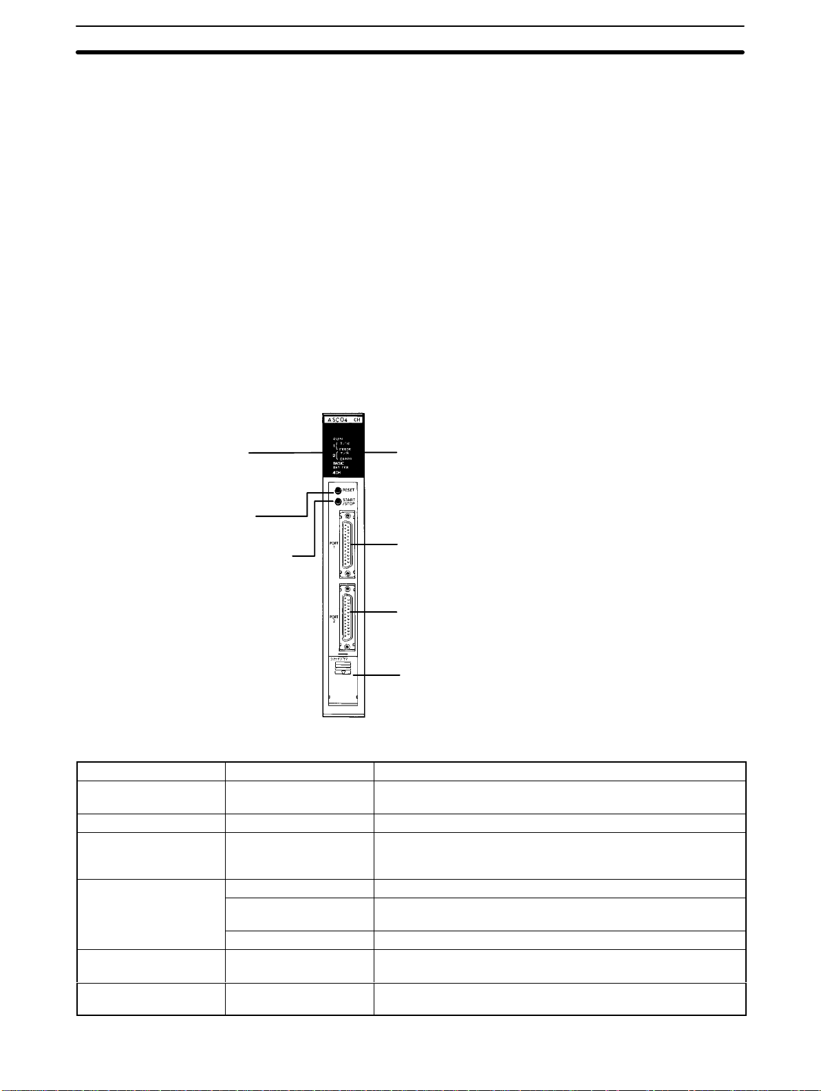
1-1 Front Panel
On the front panel of the ASCII Unit, there are six indicator lights, the reset
switch,
the ST
partment.
for setting various control parameters.
Ports The front panel of the ASCII Unit contains two RS-232C ports. These ports
are used for connecting peripheral I/O devices to the ASCII Unit. Both ports
can be used for communication devices such as printers, terminals, and modems. Only port 1 can be used for uploading or downloading a BASIC program. The standard configuration is a personal computer connected to port 1
and a printer or other I/O device connected to port 2.
Switches The START/STOP switch is a toggle switch and is used for initiating and halt-
ing execution of the ASCII Unit program.
RESET
The
Battery Compartment The battery compartment holds the C500-BAT08 Battery.
Front Panel
ART/ST
OP switch, two RS-232C
connectors, and a battery com
In addition, behind the LED Display Panel, is an 8-pin DIP switch used
switch is used for resetting the ASCII Unit.
-
LED display
Indicates the operating
status of the ASCII Unit.
RESET switch
Resets the ASCII Unit
START/STOP switch
Starts/stops BASIC
program execution.
Indicator LEDs
Name Indication Function
RUN Lit (green) Lit when the ASCII Unit is operating normally. Unlit if an error
T/R for ports 1 and 2 Blinking (green) Blinks during data transmission (port 1 and port 2).
ERROR 1 (port 1)
ERROR 2 (port 2)
BASIC
BAT ERR Blinking (red) Blinks when the battery voltage has fallen below the rated level or
4CH Lit (green) Lit when the ASCII Unit is set for 4-word mode. Unlit when the
Lit (red) Lit if a reception buffer overflows or an error such as parity error
Lit (green) Lit while the BASIC program is running.
Blinking (green) Blinks when the BASIC program stops, or when the ASCII Unit is
Unlit (green) Unlit when in monitor mode.
The following table describes the ASCII Unit’s indicators.
DIP switch
DIP switch is visible when the
indicator panel is removed.
RS-232C connector port 1
Connects peripheral devices. Is generally
used to input the BASIC program but can be
used for other peripheral devices as well.
RS-232C connector port 2
Connects peripheral devices. Cannot be
used to input a BASIC program. Is generally
used for a printer or other RS-232C devices.
Battery compartment
Holds the C500-BAT08 Battery.
occurs.
occurs (see note), or while the ASCII Unit is waiting for specific
transmission conditions to be satisfied.
waiting for input while the BASIC program is running.
if the battery is not inserted correctly.
ASCII Unit is set for 2-word mode.
2
Page 16
Front Panel Section 1-1
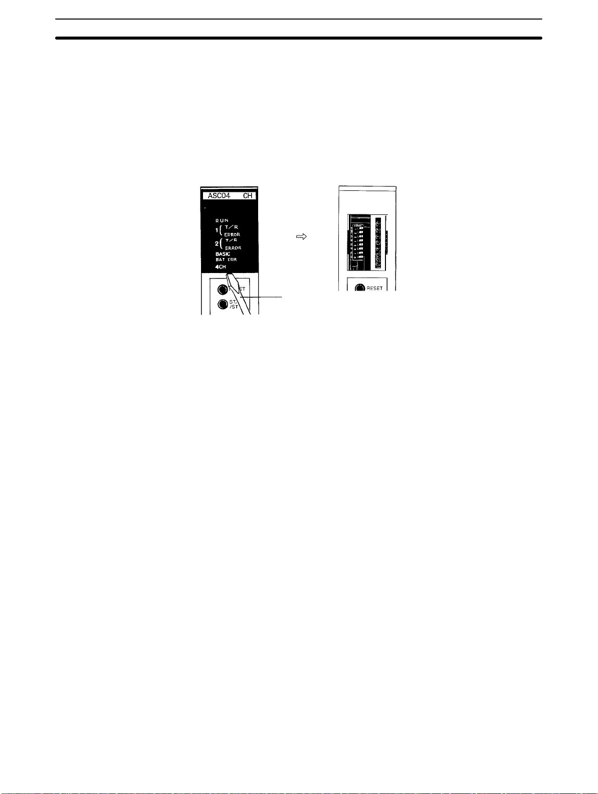
Front Panel DIP Switch
Note When
a reception buf
is
lit and will not be turned of
overflow
tor, execute the CLOSE instruction or stop the program.
In order to access the front panel DIP switch, the indicator cover must be removed
DIP
before
when mounting the ASCII Unit.
is corrected, because the error log must be kept. To turn of
with a standard screwdriver as shown in the illustration below
switch, the power
the ASCII Unit is mounted to the PC. Make sure the power to the PC is of
fer overflows or transmission error occurs, the red indicator
f even if the transmission error
to the ASCII Unit must be OFF
Standard
Screwdriver
. The DIP switch must be set
or reception buf
fer
f the indica
. T
o set the
-
f
3
Page 17
Front Panel Section 1-1
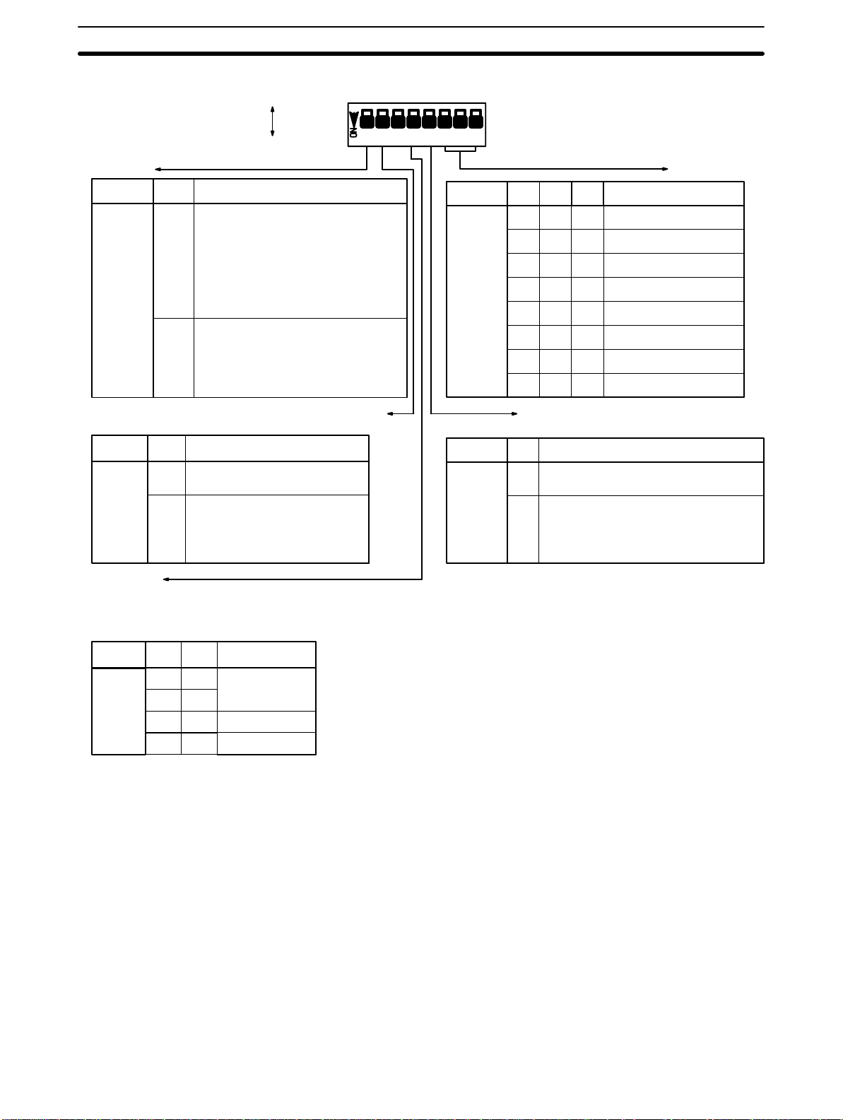
DIP Switch Settings
OFFON: 0
: 1
12345678
Start mode
Pin No. 1 Function
Setting
Automatic program transfer from EEPROM to RAM
Pin No. Function
Setting
0
1
Manual start mode
In this mode, the BASIC program is
not started upon power application.
0
To start the program, either press
the START/STOP switch or issue a
start command from the personal
computer connected to port 1.
Automatic start mode
In this mode, the BASIC program
1
is started automatically on power
application.
2
Set this pin to “0” if only the
RAM is to be used.
Set this pin to “1” to automatically transfer the program
from the EEPROM to RAM on
power application or reset.
Screen size
Pin No. Screen Size
Setting
Pin No. Function5
Setting
678
000
1
00
1
11
00
0
1
11
0
Specifies 2 or 4 word setting for
the Data Section.
Two word setting. Choose this setting
0
to use WRIT(87/191)/READ(88/190)
Four word setting. This setting is used
when the ASCII Unit is mounted to a
1
Slave Rack or when the PC does not
support WRIT(87/191)/READ(88/190).
40 columns x 7 lines
40 columns x 8 lines
40 columns x 15 lines
00
40 columns x 16 lines
0
80 columns x 15 lines
1
80 columns x 16 lines
1
80 columns x 24 lines
80 columns x 25 lines
111
Program No.
These pins select which program will be executed on power
application or reset. The program number can be changed
later with the PGEN command.
Pin No. Function34
Setting
00
10
01
11
No. 1
No. 2
No. 3
4
Page 18
Back Panel Section 1-2
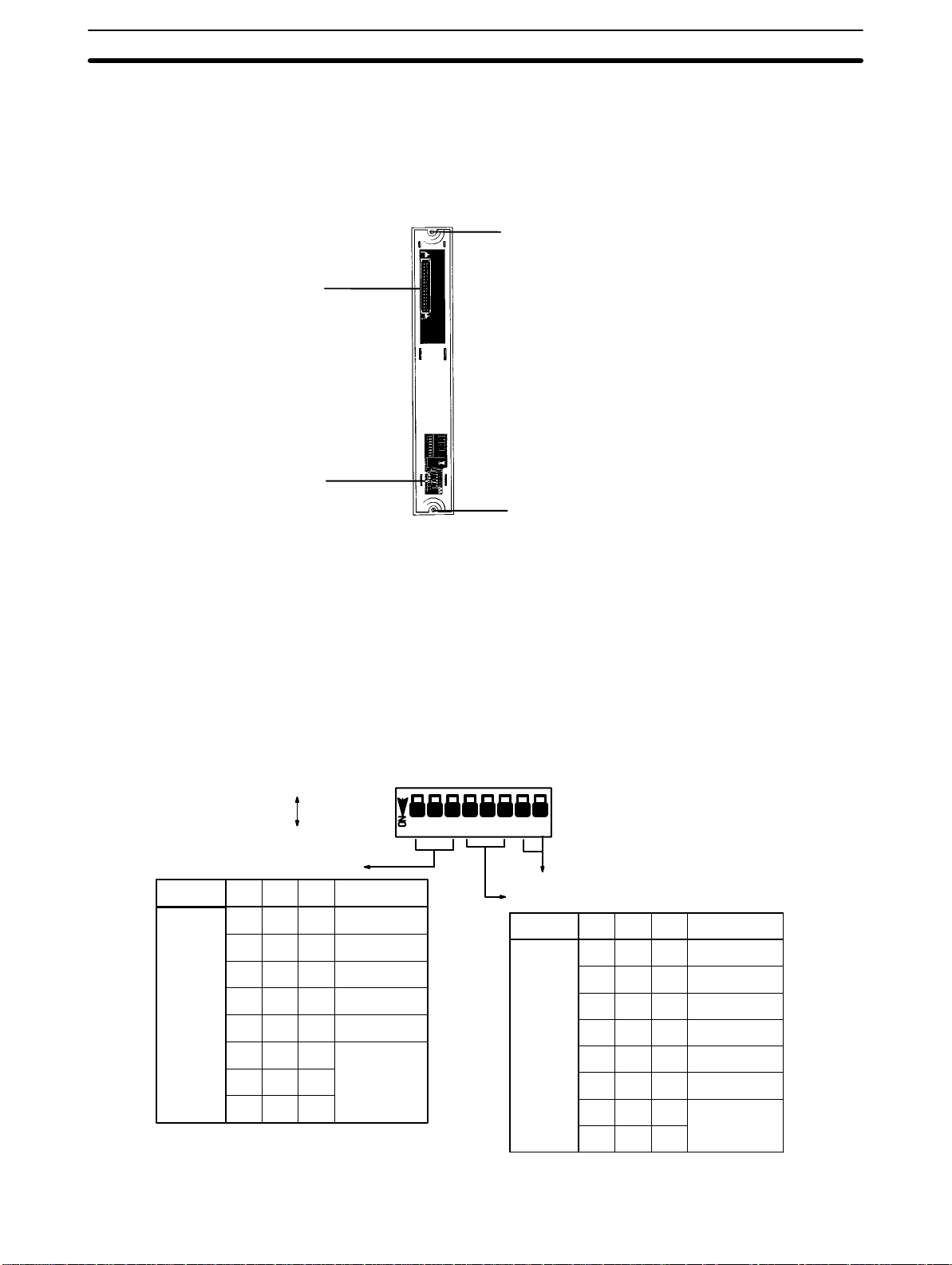
1-2 Back Panel
The back panel of the ASCII Unit houses the PC connector and an 8-pin DIP
switch used for setting the communication parameters.
Back Panel
Mounting Screw
For mounting the ASCII Unit
to the PC Rack
Connector
Connects the ASCII Unit
to the PC
DIP Switch
For setting the communication parameters
Mounting Screw
For mounting the ASCII Unit
to the PC Rack
Back Panel DIP Switch
Baud rate selection for port 1
Pin No.
Setting
123
000
1
1
0
• Pins 1, 2, and 3 are used for setting the baud rate of port 1.
• Pins 4, 5, and 6 are used for setting the baud rate of port 2.
• Pins
7 and 8 are not used but must be set to OFF
. If they are left ON, the Hard
ware Test program will be executed and all RAM data will be lost.
The DIP switch settings are described in more detail in the following diagram.
OFFON: 0
00
1
00
11
0
1
00
1
0
11
111
: 1
Baud Rate
300 bps
600 bps
1,200 bps
2,400 bps
4,800 bps
9,600 bps
12345678
Not used (Always set these pins to OFF.)
Baud rate selection for port 2
Pin No.
Setting
456
000
1
00
1
00
11
0
1
00
1
0
1
11
0
111
Baud Rate
300 bps
600 bps
1,200 bps
2,400 bps
4,800 bps
9,600 bps
19,200 bps
-
5
Page 19
ASCII Unit Internal Configuration Section 1-3
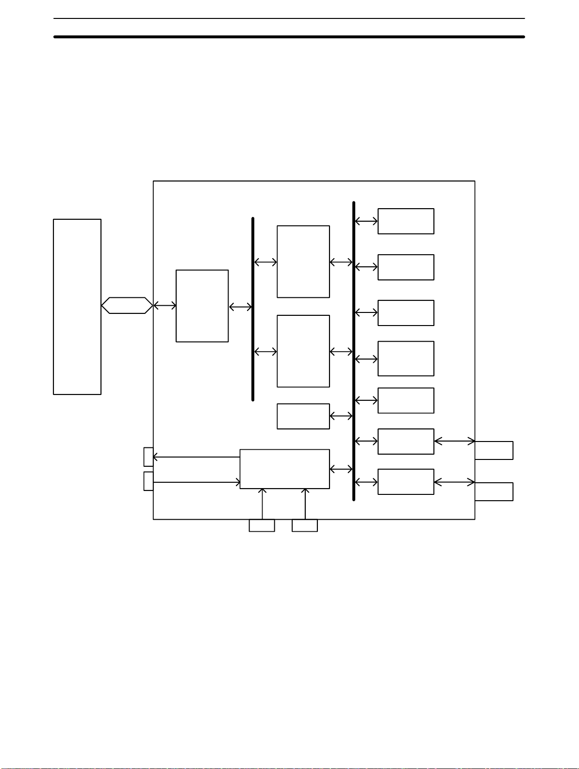
1-3 ASCII Unit Internal Configuration
The
Common Memory can be accessed using the ASCII Unit’
WRITE
READ(88/190)
statements. It can also be accessed using the PC’
instructions. I/O data can be accessed using the ASCII Unit’
GET, PC PUT, and ON PC statements. It can also be accessed using the
MOV(21/030) instruction.
The following figure illustrates these instructions and their relationship to the
Common Memory and the I/O data.
ASCII Unit
s PC READ or PC
s WRIT(87/191) and
s PC
PC
CPU
LED Indicators
DIP Switches
I/O Bus
Interface
Circuit
Common
Memory
Data
I/O
EEPROM
I/O
CPU
System
Memory
Work
Memory
BASIC
Program
Memory
BASIC Data
Memory
RS-232C
Interface
RS-232C
Interface
RS-232C
Port 1
Connectors
Port 2
RESET
START
/STOP
6
Page 20

Mounting Section 1-5
1-4 System Configuration
The ASCII Unit can be mounted to any slot on the CPU Backplane. Before
mounting
er
supply to the PC is turned OFF during installation of the ASCII Unit. A personal
computer
and
connected
tion on peripheral interface connections and timing, refer to
C500/C1000H/C2000H CV SeriesC120
the ASCII Unit, the DIP switches must be set. Make sure that the
used for entering the BASIC program should be connected to Port
other peripheral I/O devices such as a printer or a display terminal can be
to Port 2 (refer to the following diagram). For more detailed informa
Appendix B
C500
Expansion
I/O Rack
pow
.
-
1
-
1-5 Mounting
Personal Computer
The ASCII Unit can be mounted to any I/O slot. The control panel must allow
enough space for the connectors, as shown in the figure below.
Bar-code Reader
Plasma Display
*1. Height
*2. Height of the ASCII Unit with an RS-232C con-
of the ASCII Unit including the base (100
mm)
nector attached (approximately 160 to 180 mm)
Printer
7
Page 21

This section explains the words of the PC used to communicate with the ASCII Unit.
2-1
Bits and W
2-2 Data Configuration . . . . . . . . . . . . . . . . . . . . . . . . . . . . . . . . . . . . . . . . . . . . . . . . . . . . . . . .
2-2-1 Two-word Configuration . . . . . . . . . . . . . . . . . . . . . . . . . . . . . . . . . . . . . . . . . . . .
2-2-2 Four-Word Configuration . . . . . . . . . . . . . . . . . . . . . . . . . . . . . . . . . . . . . . . . . . .
ords . . . . . . . . . . . . . . . . . . . . . . . . . . . . . . . . . . . . . . . . . . . . . . . . . . . . . . . . . . .
SECTION 2
Data Allocations
9
Page 22

Data Configuration Section 2-2
2-1 Bits and Words
The
PC’
s memory is divided up into many sections, each of which has its own
unique name and purpose. The ASCII Unit can access any of these memory
using
areas
detail
IR data area that are uniquely assigned to each ASCII Unit.
The PC’s memory is organized into units called
stored in word or multiple word units. Each word has a unique address in the
computer memory and can be accessed by specifying its address.
Each
stored
one (OFF or ON). Certain bits can be accessed individually and are used as
flags.
computer or to enable or disable certain operations. Bits can also be set or
cleared
the
CPU.
For
example, when the ASCII Unit program requests data to be sent from the PC
using
that
the ASCII Unit must wait while the PC prepares the data. When the PC has
collected
proceed to read the data.
the BASIC READ and WRITE statements (this is explained in more
in
Section
word contains 16 bits. A bit is the smallest piece of information that can be
or accessed by a computer
A
flag
by the programmer to communicate certain parameters or conditions to
the BASIC GET statement, the PC’
the data,
4 BASIC Programming
is turned ON and OFF by the hardware to indicate some state of the
it turns ON the W
). However
. A bit is always
s W
rite Flag, signaling the ASCII Unit that it may
, there
are words in the PC’
words
. Information is usually
in one of two states: zero or
rite Flag is turned OFF
, indicating
s
2-2 Data Configuration
Each
ASCII Unit is assigned a section of memory in the PC. The data has two
configurations,
pin 5 of the front panel
setting
Unit.
The
basic dif
in
two-word mode the WRIT(87/191)/READ(88/190) instructions are supported
for
data transfer while in four-word mode they are not supported. The structure
and application of the words in each of the two modes is explained next.
2-2-1 Two-word Configuration
WRIT(87/191)
WRIT(87/191) is the PC’
I/O READ instruction.
When
the PC uses
can be transferred at one time. In order to transfer multiple data words at the
same
time, however
or PC WRITE statements. In addition the A or S formats
Appendix D
The following PCs support WRIT(87/191)/READ(88/190):
C500: 3G2C3-CPU11-EV1
C120: 3G2C4-SC024-EV1
All C1000H, C2000H, CV-series PCs.
When WRIT(87/191)/READ(88/190) are not supported or not used, data is
transferred
used, only one word of data is transferred at a time.
To output (word n) data using the MOV(21/030), set bits 00, 01, 02 and 03 to
zero.
for more information on formats.
using the PC’
two-word
ference between the two-word
and READ(88/190) are supported in the two-word configuration.
and
four-word
DIP switch before power is applied to the ASCII
s I/O WRITE instruction and READ(88/190)
these instructions for data transfer
, the ASCII
Unit must be programmed to use the PC READ
s MOV(21/030) instruction. When
. The data configuration is selected by
and four-word configurations is that
, up to 255 words of data
must be used. Refer to
is the PC’
the MOV(21/030) is
s
Data Bit Definitions
10
The
following table identifies the individual bits in the two words allocated to the
ASCII
Unit. In the following Bit Definition table, entries in the
Bit
column enclosed
Page 23

Data Configuration Section 2-2
in parentheses are reserved for use by WRIT(87/191)/READ(88/190) and are
not available for general programming application.
Word Bit Function Description
n (00) PC busy Reserved for WRIT(87/191)/READ(88/190)
(01) PC WRITE complete
(02) PC READ complete
03 Restart The ASCII Unit is activated when this bit goes OFF
04 to 07
08 to 15
n+1 (00) ASCII busy Reserved for WRIT(87/191)/READ(88/190)
(01) PC READ complete
(02) PC WRITE complete
03 ASCII error Turns ON when an error occurs in the ASCII Unit, when the RESET
04 Port 1 error Turns ON when a buffer overflows or transmission error occurs in Port 1.
05 Port 2 error Turns ON when a reception buffer overflows or transmission error occurs in
06 Battery error Turns ON when the battery is low or removed
07 BASIC RUN Turns ON when a BASIC program is running
08 to 15
--- Not Used
Output data bits 0 to7Data output from the PC to the ASCII Unit. Read by the PC GET statement.
activates, or when the ASCII Unit restarts.
Turns OFF when the CLOSE statement is executed or the program is
stopped.
Port 2. Turns OFF when the CLOSE statement is executed or the program is
stopped.
Input data bits 0 to 7 Data output from the ASCII Unit to the PC. Written by the PC PUT
statement.
Program Execution
PC
Application
Program
Note When
the reset switch is turned ON, the data in word n+1 will be $FFF9. Restart
ing can be checked using bit 03 of word n+1.
When the ASCII Unit is restarted, the data of word n+1 will be 0000.
following diagram illustrates how the words and bits allocated to the ASCII
The
Unit relate to program execution.
WRIT(87/191) is executed when the data communication condition for
WRIT(87/191)
is
satisfied and the ASCII busy flag is cleared. If these conditions
are not met, the WRIT(87/191) is treated as a NOP.
READ(88/190)
and
the ASCII busy flag and ASCII write
is executed when the data communication condition is
tions are not met, the READ(88/190) is treated as a NOP.
WRIT(87/191)
(n)
Common
Memory
READ(88/190)
(n+1)
MOV(21/030)/OUT Output Data
(n) 08 to 15
MOV(21/030)/LD/OR
(n+1) 08 to 15
Write Data in n
PC READ
Read data in n+1
PC WRITE
PC GET
Input Data PC PUT
complete flag are OFF
ASCII Unit
BASIC
Program
satisfied
. If these condi
-
-
Timing
The WRIT(87/191) and READ(88/190) instructions are executed
and the com
mon memory is refreshed every time the PC completes one cycle of the program. I/O data, however, does not use the common memory (see above diagram) and is refreshed when the PC refreshes all the I/O data. Consequently
11
-
Page 24
Data Configuration Section 2-2
there
is a time dif
I/O
data is set. This time dif
paring both the ASCII Unit and PC programs.
ference between when common memory data is set and when
ference must be taken into consideration when pre
-
1 cycle
MOV(21/030) WRIT(87/191)
With WRIT(87/191)
Data set in common
memory
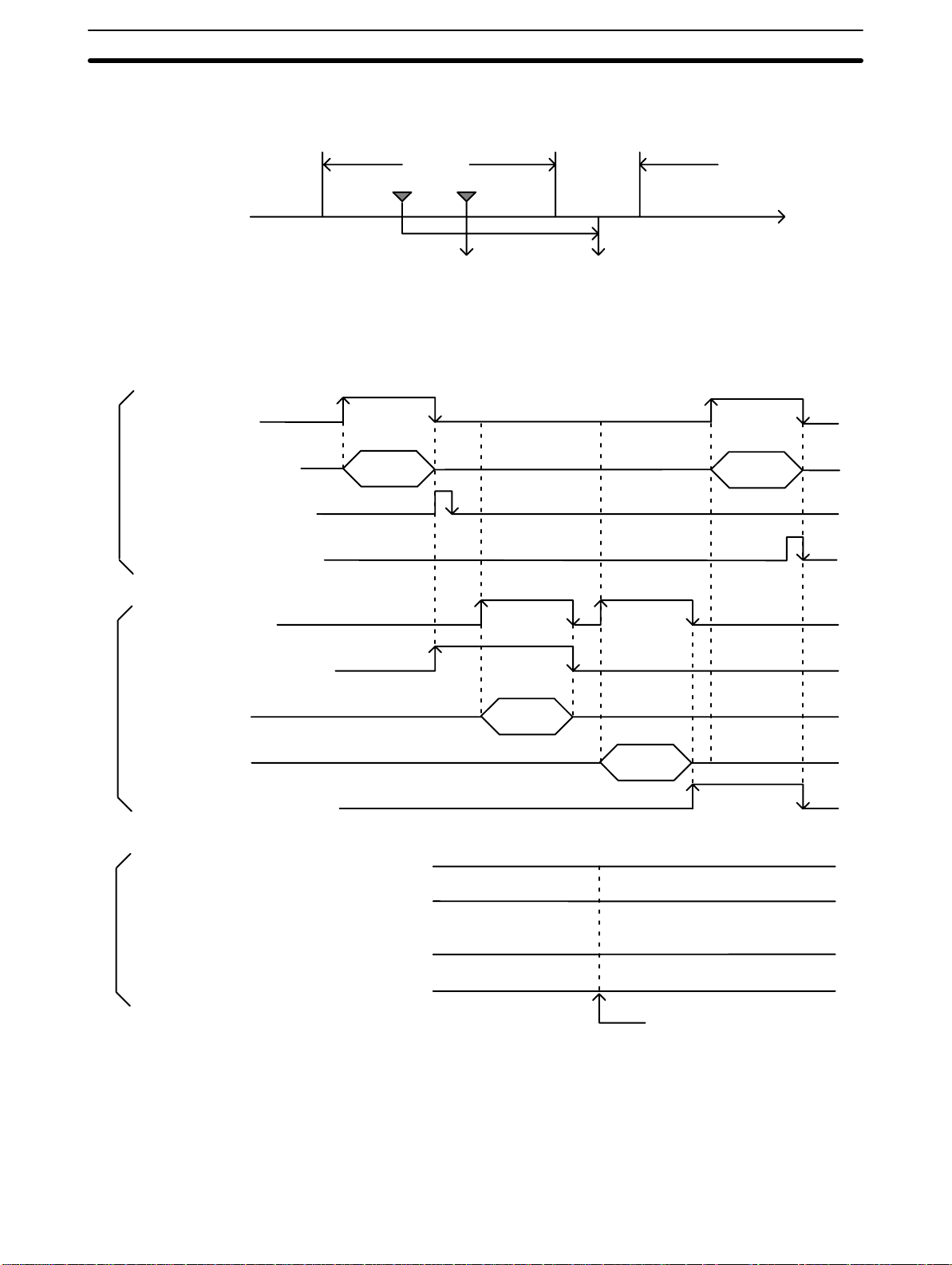
The following diagram illustrates the various timing relationships between the
PC and ASCII Unit during data transfer.
Relationship between READ and WRITE Timing
Application Program
PC busy: n (00)
Write/Read data: n or n+1
PC Unit
PC write complete: n (01)
PC read complete: n (02)
BASIC Program
ASCII busy n+1 (00)
↔ common memory
PC WRITE PC READ
PC
→ ASCII
I/O refresh
Output data set
ASCII
→ PC
time
ASCII read complete: n+1 (01)
Read data
common memory
data
Write
ASCII → common memory
ASCII write complete: n+1 (02)
→ ASCII
Relationship between Output and Input Timing
Output
data
PC → ASCII: n (08 to 15)
Input data
ASCII → PC: n+1 (08 to 15)
2-2-2 Four-Word Configuration
In four-word mode, WRIT(87/191) and READ(88/190) instructions cannot be
used.
The ASCII Unit can be
panel DIP switch to ON.
Bit Allocation The
following two tables identify the individual bits in the four words allocated to
the
ASCII Unit. Notice that words n and n+1 are used for output and words n+2
PC READ
PC → ASCII
ASCII → PC
set to four-word mode by setting pin 5 of the front
PC WRITE
PC → ASCII
ASCII → PC
I/O refresh
12
Page 25

Data Configuration Section 2-2
and n+3 are used for input. In this case, input and output are from the point of
view of the PC.
Bit Word n (OUT) Word n+1 (OUT) Word n+2 (IN) Word n+3 (IN)
00
Write Data 00 Read Data 00PC busy
01
Write Data 01
02
Write Data 02
Write Data 03
03
Write Data 04
04
Write Data 05
05
Write Data 06
06
Write Data 07
07
Write Data 08
08
Write Data 09
09
Write Data 10
10
Write Data 11
11
Write Data 12
12
Write Data 13
13
Write Data 14
14
Write Data 15
15
PC write complete
PC read complete
Restart
Interrupt No. 00
Interrupt No. 01
Interrupt No. 02
Interrupt No. 03
Output Data 00
Output Data 01
Output Data 02
Output Data 03
Output Data 04
Output Data 05
Output Data 06
Output Data 07
Read Data 01
Read Data 02
Read Data 03
Read Data 04
Read Data 05
Read Data 06
Read Data 07
Read Data 08
Read Data 09
Read Data 10
Read Data 11
Read Data 12
Read Data 13
Read Data 14
Read Data 15
ASCII busy
ASCII read complete
ASCII write complete
ASCII error
Port 1 error
Port 2 error
Battery error
BASIC RUN
Input Data 00
Input Data 01
Input Data 02
Input Data 03
Input Data 04
Input Data 05
Input Data 06
Input Data 07
13
Page 26

Data Configuration Section 2-2
Bit Definitions
Word Bit Function Description
n 00
n+1 00 PC busy Set by the PC program when the PC accesses common memory, and cleared
n+2
n+3 00 ASCII busy Set when the ASCII Unit accesses the common memory and cleared when
to 15
01 PC write
02 PC read
03 Restart The ASCII Unit is activated at the trailing edge of this flag (when the flag goes
04 to 07
08 to 15
00 to 15
01 ASCII read
02 ASCII write
03 ASCII error Set when an ASCII Unit error occurs, when RESET is activated, or when the
04 Port 1 error Set when a reception buffer overflows or transmission error occurs at Port 1.
05 Port 2 error Set when a reception buffer overflows or transmission error occurs at Port 2.
06 Battery error Set when the battery is low or removed.
07 BASIC RUN Set when the BASIC program is running.
08 to 15
Write data bits
00 to 15
complete
complete
Interrupt number
bits 00 to 03
Output data bits
00 to 07
Read data bits
00 to 15
complete
complete
Input data bits
00 to 07
Data that will be written to the common memory from the PC by the MOV(21/030)
and read with the PC READ statement.
when memory access is terminated. The ASCII Unit cannot access the common
memory while this bit is set.
Momentarily set by the PC program when the PC has completed writing data to
the common memory. When this bit goes ON, the ASCII Unit read complete flag
n+3 (01) goes ON as well.
Momentarily set by the PC program when the PC has completed reading data
from the common memory. When this bit goes ON, the ASCII Unit write complete
flag n+3 (02) goes OFF as well.
OFF). A differentiated signal must be used for the Restart signal.
Serves as an interrupt number when the ON PC statement is used.When bits 00
to 03 are converted into hexadecimal 00 to 15, 00 is ignored and 01 to 15 are
used as valid interrupt numbers.
Data output from the PC to the ASCII Unit, written by the MOV and read with the
PC GET statement.
Data that will be written to the common memory from the ASCII Unit with the PC
WRITE statement and read with the MOV.
memory access is terminated. The PC cannot access common memory while this
bit is set.
Momentarily set when the PC write complete flag goes ON enabling the ASCII
Unit to read from common memory. This flag is cleared when the ASCII Unit
terminates the read operation.
Set at the time the ASCII Unit terminates a write operation to the common
memory and cleared when the PC read complete flag goes ON.
ASCII Unit restarts.
Turns OFF when the CLOSE statement is executed or the program is stopped.
Turns OFF when the CLOSE statement is executed or the program is stopped.
Data written with the PC PUT statement and read with the MOV.
14
Note 1. Apart
08
to 15 of word n+2 can be used for program control
ting the 8-bit data to the PC.
2. When
starting can be checked using bit 03 of word n+1.
When the ASCII Unit is restarted, the data of word n+1 will be 0000.
from the data used to
read bit 00 to 15 of word n+2, the input data of bit
of the PC by transmit
the reset switch is turned ON, the data in word n+1 will
be $FFF9. Re
-
-
Page 27
Data Configuration Section 2-2
The
Program Execution
following diagram illustrates how the words and bits allocated to the ASCII
Unit relate to program execution.
rite data in n
W
PC READ
Read data in n+2
PC WRITE
PC GET
ASCII Unit
BASIC
Program
PC
Application
Program
MOV(21/030)
MOV(21/030)
MOV/OUT Output Data
MOV/LD/OR
Common
Memory
n+1 08 to 15
Input Data PC PUT
n+3 08 to 15
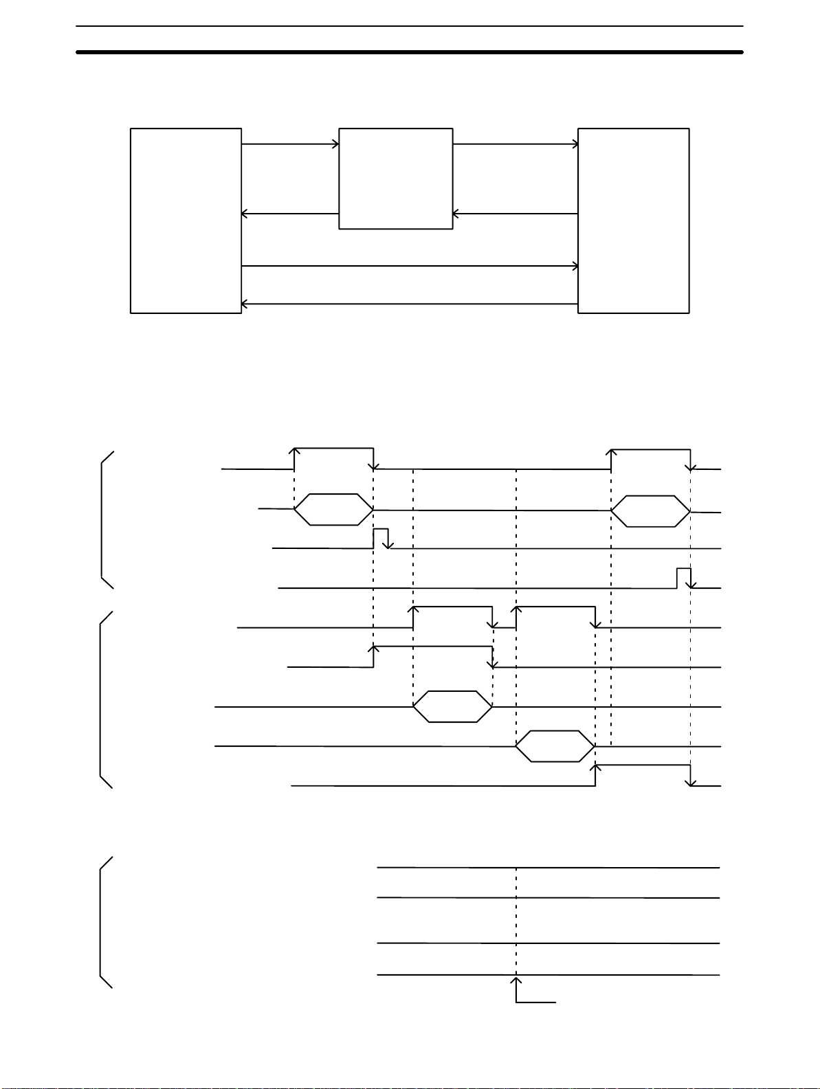
Timing The following diagram illustrates the various timing relationships between the
PC and ASCII Unit during data transfer.
Relationship between READ and WRITE Timing
Application program
PC busy: n+1 (00)
Write/Read data: n or n+2
PC Unit
PC write complete: n+1 (01)
↔ common memory
PC WRITE PC READ
PC
→ ASCII ASCII → PC
PC read complete: n+1 (02)
BASIC Program
ASCII busy n+3 (00)
ASCII read complete: n+3 (01)
Read data: n
common memory
Write data: n+2
→ common memory
ASCII
ASCII write complete: n+3 (02)
→ ASCII
Relationship between Output and Input Timing
Output
data
PC → ASCII: n+1 (08 to 15)
Input data
ASCII → PC: n+3 (08 to 15)
ASCII READ
PC READ
PC → ASCII
ASCII
→ PC
ASCII WRITE
PC WRITE
→ ASCII
PC
ASCII
→ PC
I/O refresh
15
Page 28

SECTION 3
Programming and Communications
The first part of this section explains how the ASCII Unit and the PC exchange information.
The
second part of this section explains how to transfer programs from one device to another
is written on a personal computer
gram
Unit
program can be permanently stored in the ASCII Unit’
also be transferred back to the personal computer or other storage device.
The last part of this section explains how to run a BASIC program once it has been transferred to the ASCII Unit.
3-1 Programs . . . . . . . . . . . . . . . . . . . . . . . . . . . . . . . . . . . . . . . . . . . . . . . . . . . . . . . . . . . . . . . .
3-2 Program Transfer . . . . . . . . . . . . . . . . . . . . . . . . . . . . . . . . . . . . . . . . . . . . . . . . . . . . . . . . .
3-3 Running the BASIC Program . . . . . . . . . . . . . . . . . . . . . . . . . . . . . . . . . . . . . . . . . . . . . . . .
3-4
Assembly Routines
. T
o run the program, it must be transferred to the RAM of the ASCII Unit. The ASCII
s EEPROM and also loaded from the EEPROM. The program can
. The ASCII Unit’
s BASIC pro
. . . . . . . . . . . . . . . . . . . . . . . . . . . . . . . . . . . . . . . . . . . . . . . . . . . . . . . .
-
17
Page 29
Program Transfer Section 3-2
3-1 Programs
To
use the ASCII
in
BASIC is needed. A data exchange routine must also be incorporated into the
PC program. The PC data exchange routine must set the number of words to be
transferred,
using the PC’s MOV(21/030) instruction.
There are two ways the ASCII Unit can communicate with the PC. In the first
method,
the PC controls the timing of the data transfer between
The ASCII Unit “requests” access to the PC data memory area using the PC
READ,
respond
performs
PC WRITE, PC GET
by setting either the read or write flag. The PC data exchange routine
the designated operations. When the PC is ready
is set and the ASCII Unit proceeds with the data transfer.
In the second method, the WRIT(87/191) and READ(88/190) instructions are
used
in conjunction with the PC READ, PC WRITE, PC GET
ments to transfer data.
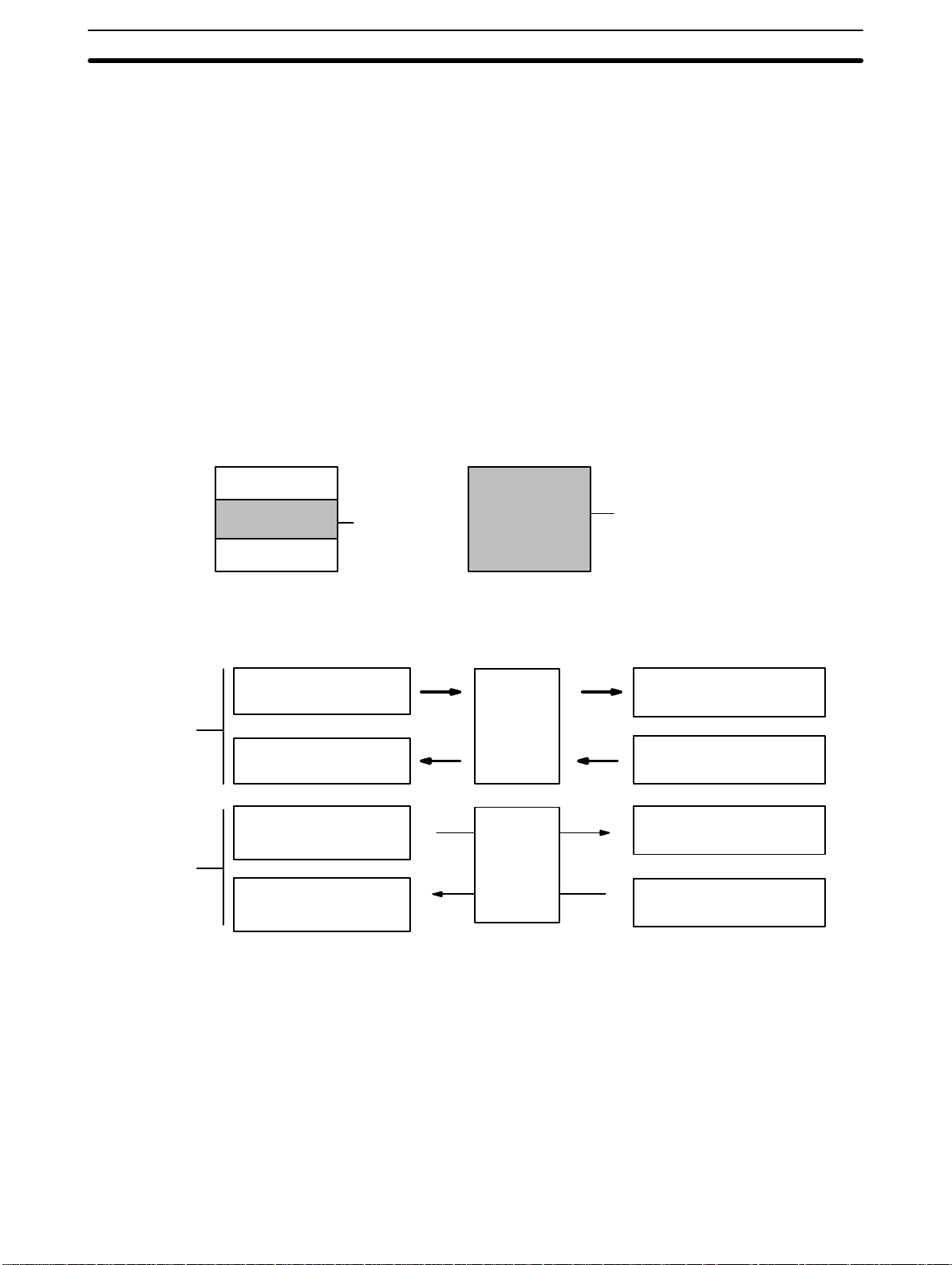
This diagram illustrates the PC and ASCII Unit programs.
Unit in conjunction with the PC, an ASCII Unit program written
the base address, and the specific memory area. This can be done
the two devices.
, or PC
PUT statements, and then waits for the PC to
, the appropriate flag
, and PC PUT
state
-
Write/read
data
exchange
I/O data
exchange
PC program
General Program
General Program
This diagram illustrates the relationship between the PC data exchange code
and the ASCII Unit program.
PC program
MOV(21/030)
MOV(21/030)
MOV(21/030), OUT, etc.
MOV(21/030), OUT, etc.
Data exchange
code
ASCII Unit program
Data exchange
processing or I/O
program
ASCII Unit program
PC READ command
Common
memory
PC WRITE command
PC GET command
I/O
memory
PC PUT command
3-2 Program Transfer
Preparation For
18
the personal computer to communicate with the ASCII Unit, set the comput
er communication software as follows:
Baud rate: same as ASCII Unit
Data length: 8 bits
Parity: none
No. stop bits: 2
Full duplex, no echo, no XON/XOFF buf
Also:
Set
the ASCII Unit DIP
Hardware
-
fer busy control, no auto line
switches to the desired configuration (refer to
feed.
Section
1
).
Page 30
Program Transfer Section 3-2
Transfer
The ASCII Unit’s BASIC or assembly language program must be written on a
personal computer which is connected to port 1 of the ASCII Unit through an
RS-232C
sonal
interface. A program can be transferred to the ASCII Unit from the per
computer or any other storage device connected to one of the communi
cation ports with the BASIC LOAD command or the S and L commands. Programs can also be transferred from the ASCII Unit’s EEPROM to the ASCII
Unit’s RAM using the LOAD command.
Programs
personal
can be transferred
computer or other storage device connected to one of the communica
from the ASCII Unit’
s RAM to the EEPROM or to a
tion ports using the BASIC SAVE command.
ASCII Unit can be booted on
The
power up by a program stored in the EEPROM.
To do this set pin 2 of the front panel DIP switch on the ASCII Unit to ON.
Note 1. During
data transfer
baud
rate settings of the computer and the
overflow
error does occur
, an overflow may occur if
, set either a slower baud rate or specify XON with
the buf
fering capacity of the
ASCII Unit are not matched. If an
the OPEN command.
2. Programs
executing
The
FIT or LSS can be used to back up BASIC programs onto
named with PNAME cannot be transferred. Delete the name
PNAME “ ” if necessary before attempting to transfer a program.
floppy disks, con
sult the FIT or LSS Operation Manual.
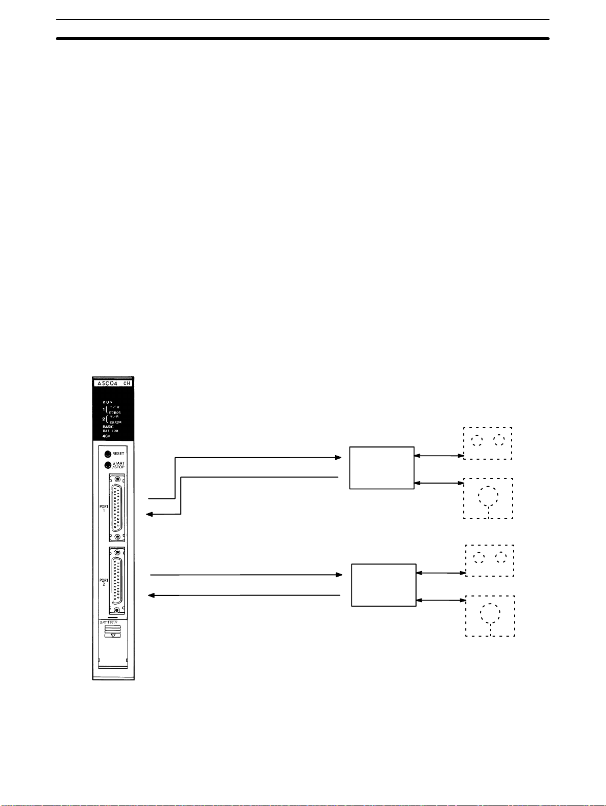
The following figure illustrates the direction of data transfer when using the
SAVE and LOAD commands.
-
-
-
by
-
SAVE #1, “COMU:”
LOAD #1, “COMU:”
SAVE #2, “COMU:”
LOAD #2, “COMU:”
Note 1. The
Refer to the explanation of the OPEN statement for details on
2.
COMU.
EEPROM’
(1)
Computer or
other peripheral device
(2)
Computer or
other peripheral device
sn lifetime is limited to 5,000 write operations.
19
Page 31

Assembly Routines Section 3-4
3-3 Running the BASIC Program
The ASCII Unit can store and access three separate BASIC programs. Each
program
gram
be done before the Unit is activated.
There are three ways to execute the specified BASIC program:
• Enter
• Press the START/STOP switch. Press it again to stop the program.
• If
has an associated program number
is to be used by setting pins 3 and 4 of the front panel DIP switch. This must
the RUN
in CTRL+X will abort the program.)
pin 1 of the front panel DIP switch is set
gram will be executed automatically when the Unit is turned ON or reset.
command from the keyboard of the personal computer
. The user can specify which pro
. (Keying
to the ON position, the specified pro
3-4 Assembly Routines
Use
the
monitor mode of the ASCII Unit for writing assembly language routines
to execute operations that cannot be processed with BASIC programs. The
ASCII Unit incorporates the Hitachi HD6303 CPU.
Assembly language routines can be written for the ASCII Unit and called from
the BASIC program with the USR statement. An assembly program can be
saved
to the
personal computer with the S command and loaded from the per
sonal computer with the L command. Assembly programs are stored in the S
format.
-
-
-
20
Page 32

SECTION 4
BASIC Programming
This
section contains an explanation of the terminology
on
the ASCII Unit. Even those familiar with BASIC should study this section carefully as many of the ASCII Unit BASIC
commands,
attention to the explanations of statements
cial
statements, and functions are non-standard, especially those that control I/O operations. Readers should pay spe
that are prefixed with “PC.” Also pay special attention to the OPEN statement.
4-1 Program Configuration . . . . . . . . . . . . . . . . . . . . . . . . . . . . . . . . . . . . . . . . . . . . . . . . . . . . .
4-2
Commands, Statements, and Functions
4-2-1 BASIC Format . . . . . . . . . . . . . . . . . . . . . . . . . . . . . . . . . . . . . . . . . . . . . . . . . . . .
4-2-2 Commands . . . . . . . . . . . . . . . . . . . . . . . . . . . . . . . . . . . . . . . . . . . . . . . . . . . . . . .
4-2-3
4-2-4
4-2-5 Arithmetic Operation Functions . . . . . . . . . . . . . . . . . . . . . . . . . . . . . . . . . . . . . .
4-2-6 Character String Functions . . . . . . . . . . . . . . . . . . . . . . . . . . . . . . . . . . . . . . . . . .
4-2-7
General Statements
Device Control Statements
Special Functions
, components, structure, and use of the BASIC programming language
. . . . . . . . . . . . . . . . . . . . . . . . . . . . . . . . . . . . . . . .
. . . . . . . . . . . . . . . . . . . . . . . . . . . . . . . . . . . . . . . . . . . . . . . .
. . . . . . . . . . . . . . . . . . . . . . . . . . . . . . . . . . . . . . . . . .
. . . . . . . . . . . . . . . . . . . . . . . . . . . . . . . . . . . . . . . . . . . . . . . . . .
-
21
Page 33

Program Configuration Section 4-1
4-1 Program Configuration
A BASIC program consists of commands, statements, and functions.
General statement
Statement
Device control statement
BASIC
Language
Command
Arithmetic operation function
Lines and Statements
Function
Basic
Statements
used
in
program lines within a program. Statements are usually created as pro
grams and executed by the RUN command. Statements can be directly input
and executed from the keyboard.
Commands
Basic
ations
external to the program such as printing and listing. Commands must be
directly
into programs and executed
into programs and executed, the commands may not work properly.
Examples: print, list, run
Functions are self-contained programs which accept one or more arguments,
perform predefined calculations, and return a result(s). There are predefined
BASIC functions for arithmetic and string operations as well as user defined
functions.
Examples: INT(x), LOG(x), SQR(x)
A
more
separated
quote marks (’) to separate comments.
Example of four statements on a line:
10 FOR L=1 TO 100: J=L*I: PRINT J: NEXT L
input and executed from the keyboard. Commands cannot be inserted
program written in BASIC is a series of lines, each of which consists of one or
statements. If several statement are written on the same line, they must be
with colons(:). A line can be no longer than 255
designate and control
are
Character string function
Special function
the flow of programs and are generally
usually entered from the command line and control oper
by
the RUN command. If commands are inserted
characters. Use single
-
-
Line Numbers Every
Character Set The
BASIC program line begins with
order
in which the program
erences for branching and editing. Line numbers must be in the range of 0 to
63999.
refer to the current line.
Examples: LIST. EDIT. AUTO DEL 100–
acters, and special characters.
The
the alphabet. The numeric characters in BASIC are the digits 0 through 9.
The following special characters are recognized by BASIC:
SP (space) ! ” # $ & ’ ( ) * + , – . / : ; < = > ? [ \ } ^ _
A period may be used in AUT
BASIC character set is comprised
alphabetic characters in BASIC are the upper case and lower case letters of
lines are stored in memory and are also used as ref
a line number
O, DELETE, EDIT
of alphabetical characters, numeric char
Constants The following can be used as constants:
22
. Line numbers indicate the
-
, and LIST commands to
-
Page 34

Program Configuration Section 4-1
Constants Character
A
Character Constants
Integers Constants
character constant is a
(”).
It can be up to 255 characters long. If it has no character
character string” or a null string.
Example: “CF-BASIC”
Whole
sign (%) can be added to specifically indicate an integer constant. Integer con
stants do not have decimal points.
Examples: 1234 –1234 12
Octal Constants Octal
to &177777 can be used.
Examples: &0127 &7777
Hexadecimal
Constants
Hexadecimal
in the range &H0000 to &HFFFF can be used.
Examples:
Numeric Integer
Real Number
character string enclosed by double quotation marks
numbers between –32768 and 32767 can be used.
numbers from 0 to 7 beginning with the prefix “&” and within the range of &0
numbers with the prefix “&H”, from
&H5E &HBF4
Decimal
Octal
Hexadecimal
Single-precision
Double-precision
, it is called an “empty
An optional percent
-
0 to F (0 to 9,A,B,C,D,E,F) and
Floating Point
Constants
1, 2, 3...
1, 2, 3...
precision: This type of constant is stored with seven-digit
output as a six-digit constant with
by one of the following methods:
1. As a number with seven or less digits: 1234.5
2. As a number in exponential form using E: 1.2E+3
3. As a number with the character “!” at the end: 2.34!
Double precision: This type of constant is stored with 16-digit precision and is
output as 16 digits or less. It is represented by one of the following methods:
1. As a number with 8 or more valid digits: 1.23456789
2. As a number in exponential form using D: –1.2D–3
3. As a number with the character “#” at the end: 2.34#
the
seventh digit rounded of
precision and is
f. It is represented
Single
Variables Variables are names used to represent values that are used in a BASIC pro-
gram. The value of a variable may be assigned as the result of calculations or
explicitly by the programmer with an assignment statement. If no value is assigned
Variable Name A
Note A
to a numeric variable, it is assumed to
character variable, it is assumed to be a null string.
variable may be up to 255 alphanumeric characters long, but only the first 16
characters are actually valid. No variable can start with “FN” or a valid BASIC
command name.
syntax error will occur if a variable begins with a reserved word (i.e., in the case
of TOT
AL or ABSOL, a syntax error will occur because T
words).
be zero. If no value is assigned to a
O and ABS are reserved
Type Declarator The
is placed after the variable name. Even if two variables have the same name,
they
Integer: Uses 2 bytes per variable.
variable TYPE must be declared. This is done using a type declarator
will be treated dif
ferently if they are declared as dif
ferent types of variables.
which
23
Page 35

Program Configuration Section 4-1
! Single-precision real: Uses 4 bytes per variable.
# Double-precision real: Uses 8 bytes per variable.
$ Character: Uses a maximum of 255 characters.
There is a second way to declare variable types. The BASIC statements DE-
FINT, DEFSTR, DEFSNG, and DEFDBL may be used to declare the types for
certain variable names.
Variable Array An
array is a group of values of the same TYPE that is
unit
by the same variable name. Each element in an array has
and
is referenced by the name of the array subscripted with an integer or
expression.
There
can be many dimensions to an array
two,
and three dimensional
sion in the array.
For example, T(4) would reference the fourth element in the one-dimensional
array T. R(2,3) would reference the value located in the second row and third
column of the two-dimensional array R.
maximum number of
The
of
elements per dimension is 32767. The array
must be declared with
of the first element
tion
TYPE.
arrays. An array has one subscript for each dimen
dimensions of an array is 255. The maximum number
the
DIM statement. The subscript value zero is the posi
in an array
. All elements of an array must be of the same
. The most common types are one,
stored and referenced as a
a unique position
integer
size and number of dimensions
Type Conversion When necessary, BASIC will convert a numeric constant from one TYPE to
another. The following rules and examples apply:
1, 2, 3...
1. If
the numeric data on
the
type of data on the
However,
sa.
Example: A = 12.3: if A is an integer then, “12” is assigned to A.
2. Double-precision
to a single-precision variable.
Example:
IF “A” is a single-precision variable and the statement:
LET
verted to a single-precision number and then assigned to “A.”
3. When
double-precision values, the single-precision value is converted to
double-precision first, and then the operation is performed. Therefore, the
result is a double-precision value.
Example: 0#/3 (double-precision)
4. In
logic operations, all numeric data is first converted into integer data. If any
value cannot be converted into an integer within the range of –32768 to
32767, an error will occur.
Example: LET A = NOT 12.34, –13 is assigned as A.
5. When
the decimal point is rounded off.
Example: A = 12.3: “12” is assigned to A.
character data cannot be converted to numerical data, or vice ver
A = 12.3456789# occurs in a program, then 12.3456789# will be con
an arithmetic operation is performed using both single-precision
a real number is converted into an integer
the right side of an assignment statement dif
left side, the right side is converted to match the left.
data is converted to single-precision data when assigned
, everything to the right of
fers from
and
-
-
-
-
Expressions Expressions refer to constants, variables, and functions that have been com-
bined by operators. Numeric values, variables, or characters alone can also
form expressions. There are four types of expressions:
• Arithmetic
24
Page 36

Program Configuration Section 4-1
• Relational
• Logical
• Character
Of
these,
the first three produce numeric values as a result, and are thus called,
“numeric expressions.” The last type is called a “character expression.”
An
Arithmetic Operators
Arithmetic Operator Example Operation
arithmetic expression is made up of constants, variables, and functions com
using arithmetic operators. A list of valid arithmetic operators is shown
bined
the following table.
in
-
+
–
*
/
\
MOD
^
Relational Operators
Relational Operator Example Operation
=
<>,><
A + B
A – B, –A
A * B
A / B
A \ B
A MOD B
A ^ B
Note If A or B is a real number in an expression using the \ or MOD operator
mal
part is first rounded up to convert the real number into an integer, and then
Addition
Subtraction or negation
Multiplication
Real number division
Integer division
Remainder after integer division
Exponentiation
, the deci
the operation is performed.
Relational
operators
compare two values. The output is “–1” (&HFFFF) if the two
values are equal and “0” if they are not.
A = B
A <> B
Equal
Not equal
-
<
>
≤
≥
Character Operator A
character expression is made up of character constants and variables that are
linked with the character operator
“+” operator links the characters together to form one character value.
Input: A$=“CF” B$=“BASIC” PRINT A$+“–”+B$
Output: “CF–BASIC” is displayed.
Logical Operators Logical
ean
operations. The logical operator returns a bit result which is either “true”
0)
or
“false” (0). In an expression, logical operations are performed after arithme
and relational operations. The outcome of a logical operation is determined
tic
A < B
A > B
A
≤ B
A
≥ B
Less than
Greater than
Less than or equal to
Greater than or equal to
“+”. Instead of adding characters together
, the
Operators perform tests on multiple relations, bit manipulation, or bool
(not
25
-
-
Page 37

Program Configuration Section 4-1
as shown in the following table. The operators are listed in the order of precedence.
Logical Operator Description, Example, and Result
NOT (negation)
AND (logical product)
OR (logical sum)
XOR (exclusive-OR)
A
1
0
A B A AND B
1 1
1 0
0 1
0 0
A B A OR B
1 1
1 0
0 1
0 0
A B A XOR B
1 1
1 0
0 1
0 0
NOT A
0
1
1
0
0
0
1
1
1
0
0
1
1
0
IMP (implication)
EQV (equivalence)
A B A IMP B
1 1
1 0
0 1
0 0
A B A EQV B
1 1
1 0
0 1
0 0
1
0
1
1
1
0
0
1
Operator Priority Arithmetic and logical operations are performed in the following order. Note,
however, that an expression or function enclosed by parentheses is executed
first, irrespective of operator priority.
1. ^ (exponentiation) 8. NOT
2. – (negation) 9. AND
3.
4. \ 11. XOR
5. MOD 12. EQV
6. +. – 13. IMP
7. Relational operators
*, /
10. OR
26
Page 38

Commands, Statements, and Functions Section 4-2
Calculation Examples of Logical Expressions
NOT (negation)
A =1= 0000000000000001
NOT 1 = 1111111111111110 = –2
NOT A = –2
AND (logical product)
A = 5 = 0000000000000101
B = 6 = 0000000000000110
A AND B = 0000000000000100 = 4
OR (logical sum)
A = 4 = 0000000000000100
B = 3 = 0000000000000011
A OR B = 0000000000000111 = 7
XOR (exclusive OR)
A = –4 = 1111111111111100
B = 5 = 0000000000000101
A XOR B = 1
EQV (equivalent)
A = –4 =1111111111111100
B = 5 = 0000000000000101
A EQV B = 0000000000000110 = 6
IMP (implication)
A = –4 = 1111111111111100
B = 5 = 0000000000000101
A IMP B = 0000000000000111 = 7
111111111111001 = –7
4-2 Commands, Statements, and Functions
This section explains, in detail, the BASIC commands, statements and functions.
They are presented in alphabetical order by section. Each description is
formatted as described below.
4-2-1 BASIC Format
Purpose: Explains the purpose or use of the instruction
Format: Shows the correct format for the instruction
The following rules apply to the format descriptions of all commands, instructions, and functions:
• Items in CAPITAL LETTERS must be input as shown.
• Items
• Items in square brackets ([ ]) are optional.
• All punctuation marks except angle and square brackets (i.e., comas, hy-
• Arguments to functions are always enclosed in parentheses. In the formats
in lower case letters enclosed in angle brackets (< >) are to be supplied
by the user.
phens, semicolons, parentheses, and equal signs) must be included where
shown.
for the functions in this chapter
given
follows:
x and y : represent numeric expressions
I and J : represent integer expressions
A$ and B$ : represent string expressions
, the arguments have
been abbreviated as
27
Page 39

Commands, Statements, and Functions Section 4-2
Remarks: Explain in detail how to use the instruction
Examples: Show sample code to demonstrate the use of the instruction
4-2-2 Commands
This section describes all of the BASIC commands for the ASCII Unit.
AUTO Command
CONT Command
Purpose: To automatically generate line numbers for each line of the pro-
gram
Format
Examples: AUTO 100, 10
Remarks:
Auto
by <increment>. The default value for both <line> and <increment> is 10.
The AUTO Command can be canceled by entering CTRL+C.
If
diately
the
line number unchanged.
Purpose: To resume execution of a program after a Ctrl+Break has been
: AUTO [<line>][,[<increment>]]
<line> is a an integer from 0 to 63999.
<increment> is an integer value that specifies the increment of
the generated line numbers.
AUTO 500, 100
begins numbering at <line> and increments each subsequent line number
an already existing line number is specified, an asterisk (*) is displayed imme
after the line number
new line number will be used instead. Pressing only the CR key leaves the
typed, a STOP or END statement has been executed, or an error
has occurred
. If a new line number is input followed by a CR key
,
DEL Command
Format
Remarks:
Execution
during
gram cannot be resumed.
If the program is modified after execution has been stopped, the program can
not be resumed.
CONT is usually used in conjunction with STOP for debugging.
Purpose: To Delete the specified program lines
Format: DEL [<first>] [-<last>] or DEL <first> -
Examples
DEL 100 Deletes line 100
DEL 100- Deletes all lines from line 100
DEL -150 Deletes all lines up to line 150
DEL 100-150 Deletes all lines between 100 and 150
: CONT
resumes at the point where
data exchange with an external device, execution is aborted and the pro
<first> is the first line number deleted.
<last> is the last line number deleted.
:
the break occurred. If CTRL+X is pressed
-
28
Page 40

Commands, Statements, and Functions Section 4-2
Remarks:
A period may be used in place of the line number to indicate the current line.
EDIT Command
LIST Command
Purpose: To Edit one line of the program
Format: EDIT <line>
<line> is the line number to be edited.
Remarks:
The
EDIT Command is used to display a specified line and to position the cursor
at
the beginning of that line. The cursor can then be moved within the specified
line
and characters can be inserted or
the previously entered program line. “.” refers to the last line referenced by an
EDIT statement, LIST statement, of error message.
Purpose: To list the program currently in memory on the screen or other
specified device
Format: LIST [<line>] [-[<line>]]
LLIST [<line>] [-[<line>]]
<line> is a valid line number from 0 to 63339.
deleted. Executing “EDIT .” will bring up
LOAD Command
1, 2, 3...
Remarks:
LIST
displays a program or
vice.
If the line range is omitted, the entire program is listed. “LIST
the line that was last input or was last displayed.
can be aborted by entering CTRL+B or CTRL+X. If CTRL+B is used, list
Output
ing can be resumed by entering CTRL+B again.
LIST/LLIST
ment
tus.
The LIST Command automatically outputs to port 1 and the LLIST Command
automatically outputs to port 2.
The LLIST Command outputs data to the device “LPRT” independently of the
OPEN statement.
When the dash (-) is used in a line range, three options are available:
1. If
listed.
2. If only the second number is given, all lines from the beginning of the program through the given line are listed.
3. If both numbers are given, the inclusive range is listed.
Examples
LIST -500 List everything up to line 500
LIST 10-100 List all lines ranging from 10 through 100
LIST 200- List everything from line 200 on
Purpose: To load a program from the EPROM into memory
Commands can be written into the program, but
will not be executed and the ASCII Unit will enter command input wait sta
only the first number is given, that line and all higher numbered lines are
:
a range of lines on the screen or other specified de
.” displays or prints
the following state
-
-
-
-
Format
Remarks
The contents of the program area specified with the MSET Command are
loaded from the EEPROM.
: LOAD
:
29
Page 41

Commands, Statements, and Functions Section 4-2
Purpose: To load a program sent from an RS-232C device to the current
program area
MON Command
Format
Example: LOAD #1,”COMU:(43)
Remarks:
When this command is executed, the BASIC indicator LED will begin blinking
rapidly. Make sure the RS-232C device is connected at this time.
During
put from port 1 will not be acknowledged.
The program area currently used is cleared immediately after the LOAD command is executed.
For
the OPEN instruction.
Purpose: To change to monitor mode
Format: MON
: LOAD #<port>,“COMU:[<spec>,<vsl>]
<port> is either port 1 or port 2.
<spec>: see OPEN statement tables.
<vsl>: valid signal line––refer to the OPEN statement tables.
execution of the LOAD command, the ST
details on communication parameters, valid signal lines, and COMU refer to
ART/ST
OP switch and key in
-
MSET Command
Remarks:
This Command passes control from BASIC mode to monitor mode.
To return to BASIC mode, enter CTRL+B.
In monitor mode, all Roman characters used must be in upper case.
Purpose
Format: MSET [<address>]
Example
Remarks
When
special memory space must be reserved for the assembly program.
The MSET command sets the lowest possible address that a BASIC program
can
memory.
“fit”.
If
no MSET address is specified, the default MSET boundary address will be set
at
will be overwritten.
The
turned OFF. To cancel the effect of this command, execute MSET &H2000.
: To reserve memory space for an assembly program
<address> is a hexadecimal number between &H200 and
&H7FFF.
: MSET &H5000
:
an assembly program is to be used in conjunction with a BASIC program,
occupy
&H2000. Do not specify an address higher than &H7FFF or the system
address specified by this command is maintained even if system power is
. The assembly program is then stored “below” the BASIC program in
It is necessary to reserve enough space for the assembly program to
stack
30
Page 42

Commands, Statements, and Functions Section 4-2
This diagram illustrates the PC memory map before and after the MSET command is executed.
&H0000
&H0020
&H2000
&H8000
&HFFFF
NEW Command
Under normal conditions
I/O Area
System area
Basic text area
System stack area
Character String area
System area
Purpose: To delete the program currently in memory and clear all variables
Format: NEW
Remarks:
New
is used to clear memory before a new program
files and ports to be closed.
Programs
therefore
executed.
When MSET is executed
&H0000
&H0020
&H2000
&H5000
(Standard 1K byte)
&H8000
&HFFFF
I/O Area
System area
Assembly language
program area
Basic text area
System stack area
Character String area
System area
(Standard 1K byte)
is entered. New causes all
named with
the PNAME command cannot be erased. The name must
be erased first by executing PNAME “ ” before the NEW command is
PGEN Command
PINF Command
Purpose
: To select one of three program areas for the current program
Format: PGEN <num>
<num> is an integer of value 1, 2, or 3.
Remarks
The
:
occupied capacity of the selected program area
will be displayed. (Refer to
the discussion of the PINF command.)
Purpose
: To display memory area information
Format: PINF [<arg>]
<arg> is either an integer of value 1, 2, or 3 or the character
string “ALL”. ALL is entered without quotes.
Examples
: PINF 1
PINF ALL
Remarks
This
the
:
Command displays the amount of program
area currently being used and
program names that have been assigned by the PNAME command. Specify
1, 2, or 3 as <arg> for a specific program area.
31
Page 43

Commands, Statements, and Functions Section 4-2
If <arg> is not specified, information on the area currently being used is displayed.
If ALL is specified, information on all three program areas will be displayed.
PNAME Command
Purpose: To assign a name to a program stored in the area specified with
the PGEN command or to cancel a previously assigned program
name
Format: PNAME <string>
<string> is the chosen name (enclosed in quotes) for the program or the null string, “ ”.
RENUM Command
Examples
Remarks
The chosen name must be eight characters or less.
Program
execution of the LOAD and NEW commands which erase program area contents.
command before execution of the LOAD or NEW commands.
Purpose: To renumber program lines
Format: RENUM [<new number>] [,[<old number>][,<inc>]]
Examples
: PNAME “PROG1”
PNAME “ ”
:
areas assigned a name with the PNAME command are protected from
It is necessary to erase all assigned program names with the PNAME “ ”
<new number> is the first line number to be used in the new sequence. The default is 10.
<old number> is the line in the current program where the renumbering is to begin. The default is the first line of the program.
<inc> is the increment to be used in the new sequence. The default is 10.
: RENUM 200
RENUM 500, 200, 10
RUN Command
32
Remarks:
RENUM
THEN, ELSE, ON ... GOTO, ON ... GOSUB, RESTORE, RENAME, and ERL
statements to reflect the new line numbers.
Statement numbers greater than 63999 cannot be used.
Purpose
Format: RUN [<line>]
Remarks
If
a line number is specified, execution begins from that line. If the line number is
omitted, execution starts from the first line of the program.
The
ing the designated program.
Program
Program
STOP statement.
will also change all line number references following GOT
: To execute a program
<line> is any line number less than 63999.
:
RUN
command clears all variables and closes all open files before execut
execution can be aborted with CTRL+X, or the ST
execution can also be aborted from within the program by an END or
ART/ST
O, GOSUB,
OP switch.
-
Page 44

Commands, Statements, and Functions Section 4-2
SAVE Command
TRON and TROFF Commands
Purpose: To write the program area to the EEPROM
Format
Remarks:
The
area reserved with the MSET command are written to the EEPROM.
If
the process will be aborted.
Purpose: To write a program in the current program area to a storage de-
Format: SAVE #<port>,“COMU:[(<valid signal line>)]”
Example
Remarks
When
blink
When the device is set, press the START/STOP switch.
During execution of this command the START/STOP switch and key input
through port 1 are inhibited.
For further details on COMU refer to the OPEN command.
Purpose: To trace execution of a program
:SAVE
contents of the BASIC program area and the assembly language
the ST
ART/ST
: SAVE #1,“COMU:(43)”
:
this command is executed, the BASIC LED indicator
rapidly warning the user to prepare the peripheral device for data transfer
OP switch is pressed during execution of the SAVE command,
vice connected to one of the ports.
<port> is one of the two ports (1,2).
<valid signal line>: refer to the OPEN statement tables.
on the ASCII Unit will
program
.
Format
Remarks
The
TRON command is a debugging tool that enables the programmer to follow
the execution of a program line by line. Execution of the TRON command will
cause
the screen as they are executed.
trace
The
turning off the power or, with the RESET switch.
VERIFY Command
Purpose: To verify the contents of the EEPROM by comparing them to the
Format: VERIFY
Remarks
If the contents of the program area are identical to those of the EEPROM, the
message
is displayed.
4-2-3 General Statements
CLEAR Statement
Purpose: To initialize numeric and character variables and set the size of
: TRON
:
the line
numbers of subsequent program statements to be displayed on
can be canceled with the TROFF command, the NEW command, by
contents of the program area
:
“READY” will be displayed;
the character memory area
otherwise, the message “PROM ERROR”
Example
: CLEAR [<size>]
<size> is the size of memory area used to process character
strings and is specified in byte units.
33
Page 45

Commands, Statements, and Functions Section 4-2
Remarks:
This command initializes numeric variables to zero and character strings to
empty. It also clears all user functions defined by the DEF FN statement.
This statement must be executed before the ON ERROR GOTO statement.
<size> is automatically set to 200 bytes upon power application or after reset.
COM Statement
Purpose: To enable, disable, or stop an interrupt defined by the ON COM
GOSUB statement.
Format: COM[<port number>] ON/OFF/STOP
<port number> is an integer (1 or 2).
Example: COM1 ON
Remarks
The
statement.
After
data
ecution
ment.
The COM OFF statement disables the com port interrupts. Even if data
to a com port buffer, branching will not take place.
The COM STOP statement stops the com port interrupts from branching program
branching
terrupt will then take place.
If no port number is specified, port 1 is selected as the default port.
Execute the COM OFF statement at the end of the program.
The COM ON/OFF/STOP statement can be executed only after the ON COM
GOSUB statement has been executed.
Program Example:
10 OPEN #2, “COMU:”
20 ON COM2 GOSUB 100
30 COM2 ON
40 GOTO 40
100 IF LOC(2)<>0 THEN A$=INPUT$ (LOC(2), #2)
110 RETURN
:
COM ON statement enables an interrupt defined by the ON COM GOSUB
this statement has been executed, an interrupt will be generated each time
is written to the specified port buf
to branch to a routine defined by the associated ON COM GOSUB state
execution. However
to the specified interrupt
, if
the COM ON statement is subsequently executed,
fer
. The interrupt will cause program ex
service routine based on the “ST
is
written
OPPED” in
-
-
-
DATA Statement
34
Purpose: Defines numeric and character constants to be specified in a
subsequent READ statement
Format: DATA <constant>[,<constant>]...
<constant> may be a numeric constant in any format; i.e.,
fixed-point, floating-point, or integer. <constant> can also be a
character string. Quotes are only necessary if the constant contains comas, colons, or spaces.
Example
Remarks
Any
access
: DATA CF, 10, 2.5, “A.:B”
:
number of DATA statements can be used in a program. READ statements
DATA statements in order (by line
number). The data contained therein
Page 46

Commands, Statements, and Functions Section 4-2
may
be thought of as one continuous list of items, regardless of how many items
are on a line or where the lines are placed in the program.
DATA statements are non-executable and can be placed anywhere in a pro-
gram. A data statement can contain as many constants as will fit on one line
(separated by comas).
variable type given in the READ statement must agree with the correspond
The
ing constant in the DATA statement.
DATA
DEF FN statement
statements may be re-read from the beginning by use
statement.
No comment (with “:” or “’”) can be written after the DATA statement.
Purpose
Format: DEF FN<name>[(<arg1>[,<arg2>]...)] = <def>
: To define and name a function written by the user
<name>, which must be a legal variable name, is the name of
the function.
<argn> is a list of variable names called parameters that will be
replaced with values calculated when the function is called. The
items in the list are separated by comas.
<def> is an expression that performs the operation of the function and is limited to one line.
of the REST
ORE
-
Example
Remarks:
A user function must be defined with the DEF FN statement before it can be
called. To call a user function once it has been defined, append FN to the assigned name of the function and set it equal to some variable.
distance = FNA(X,5,5)
Variable
function; they do not affect program variables that have the same name.
The variables in the parameter list represent, on a one-to-one basis, the
argument variables or values that will be given in the function call.
This
fied
it is returned to the calling statement.
If
a type is specified in the function name and the argument type does not match,
an error will occur.
DEF INT/SNG/DBL/STR Statement
Purpose
Format: DEF <type><letter>[-<letter>]
: DEF FNA (X, Y, Z) = SQR(X**2 + Y**2 + Z**2)
names that appear in the defining expression serve only to define the
statement may define either
in the function name, the value of the expression is
: To declare variable types as integer, single-precision,
double-precision, or string
[<letter>[-<letter>]]...
<type> is INT, SNG, DBL, or STR
numeric or string functions. If a type is speci
forced to that type before
-
Remarks:
Any
variable names beginning with
signed to the specified variable type.
The
“”, “!”, and “$” declaration characters take precedence over a DEF <type>
statement.
If
no type declaration statements are encountered, BASIC
without declaration characters to be single-precision variables.
the <letter(s)> listed will automatically be as
assumes all variables
-
35
Page 47

Commands, Statements, and Functions Section 4-2
DEF USER Statement
Example: DEFINT
All variables beginning with A, B, C, D, and X will be integer variables.
Purpose: To specify the starting address of an assembly language subrou-
tine that will be called via the USR function
Format: DEF USR [<digit>] = <offset>
<digit> is an integer from 0 to 9. The digit corresponds to the
USR routine number whose address is being specified. If <digit>
is omitted, DEF USR0 is assumed.
<offset> is the starting address of the USR routine.
Remarks:
Any
number of DEF USR
routine
essary.
Program Example:
starting addresses,
100 DEF USR1=&H2100
110
120 A=USR1 (A)
130
POKE &H2100, &H39
PRINT A
A-D, X
statements may appear in a program to redefine sub
thus allowing access to as many subroutines as nec
-
-
DIM Statement
END Statement
Purpose: To specify the maximum values for array variable subscripts and
allocate storage accordingly
Format: DIM <variable>(<subscripts>)
[ ,<variable>(<subscripts>)]...
<variable> is a legal variable name.
<subscripts> are the maximum number of elements for each di-
mension of the array. There can be up to 255 subscripts but the
maximum size of the array cannot exceed the amount of memory
available.
Example
Remarks:
If
an array variable name is used without a DIM statement, the maximum value of
the
than
script is zero.
The
array elements are initialized to NULL.
Purpose: To terminate program execution, close all files, and return to
: DIM A (10,20), B$(30)
array’
s subscript(s) is assumed
the maximum specified, an error will occur
DIM
statement initializes all the elements of numeric arrays to zero. String
command level
to be 10. If a subscript is used that is greater
. The minimum value
for a sub
-
36
Format: END
Remarks:
END statements may be placed anywhere in the program to terminate execution.
Unlike the ST
statement
mand level after an END is executed.
at the end of the program
OP statement, END closes all open
is optional. BASIC always returns to com
files or devices. An END
-
Page 48

Commands, Statements, and Functions Section 4-2
ERROR Statement
FOR and NEXT Statements
Purpose: To simulate the occurrence of an error, or to allow error codes to
be defined by the user
Format
Remarks:
Error code numbers 1 to 255 are predefined and reserved by BASIC. Higher
numbers
codes
program to an error handling routine.
When
GOTO
ber
ROR is displayed if an undefined error occurs.
The
error occurred is assigned to the variable ERL.
Purpose
Format
: ERROR <n>
<n> is the error code to be simulated.
can be used for user-defined error code messages. User-defined error
can be used together with the ON ERROR GOT
the ERROR statement is executed without an accompanying ON ERROR
statement,
is output and program execution is stopped. The message UNDEFINED ER
error
number is assigned to the variable ERR and the line number where the
: To allow a series of instructions to be performed in a loop a given
: For <var>=<x> TO <y> [STEP<z>]
the error message corresponding to the specified error num
number of times
O statement to branch the
-
-
<x>, <y>, and <z> are numeric expressions.
Example: 100 FOR Y = base TO 10 STEP 2
1
10 NEXT Y
Remarks:
<var>
is used as a counter
of the counter. The second numeric expression (<y>) is the final value of the
counter.
The program lines following the FOR statement are executed until the NEXT
statement
cified
A
check is performed to see if the value of the counter is now
final value (<y>). If it is not greater, execution branches back to the first statement
tion continues with the statement following the NEXT statement. This is a
FOR...NEXT loop.
STEP is not specified, the increment is assumed to be
If
the
until the counter is less than the final value.
The
er than the final value.
NESTED LOOPS
FOR...NEXT
loop.
counter. The NEXT statement for the inside loop must come before the NEXT
statement for the outer loop.
If
nested loops have the same end point, the same NEXT statement can be used
for both of them.
If a NEXT statement is encountered before its corresponding FOR statement,
an error message is issued and execution is terminated.
is encountered. Then the counter is incremented by the amount spe
by STEP
after the FOR statement and the process is repeated. If it
counter will count down instead of up. In this case, the loop will be executed
body of the loop will never be executed if the initial value of the loop is great
When loops are nested, each loop must have a unique variable name for its
.
loops may be nested, that
. The first numeric expression (<x>) is the initial value
greater than the
is greater
one. If STEP is negative,
is, a loop can be placed inside of another
, execu
-
-
-
37
Page 49

Commands, Statements, and Functions Section 4-2
GOSUB and RETURN Statements
Purpose: To branch to and return from a subroutine
Format: GOSUB <line>
Remarks
A
subroutine may be called any number of times in
may be called from within another subroutine.
The
the statement following the most recent GOSUB statement.
subroutine may contain more than one RETURN statement should logic dic
A
tate a return at different points in the subroutine.
Subroutines can appear anywhere in the program, but it is recommended that
subroutines be readily distinguishable from the main program.
To
by a STOP, END, or GOTO statement to direct program execution around the
subroutine.
Program Example
10 T = Time
20 GOSUB 100
30 {stuff}
40 .
50 .
60 .
90 GOTO 150
100
110 T = T + TIME
120 RETURN
130 {stuff}
<line> is the first line number of the subroutine.
:
a program, and a subroutine
RETURN statement(s) in a subroutine causes execution to branch back to
-
prevent inadvertent entry into a subroutine, the subroutine may be preceded
:
GOTO Statement
IF...THEN Statements
38
Purpose
Format: GOTO <line>
Remarks:
If <line> is a non-executable statement, execution will proceed at the first ex-
ecutable statement encountered after <line>.
Purpose
Format
Example: IF B=10 THEN PRINT “hello” ELSE 500
: To unconditionally branch program execution to the specified line
number
<line> is a valid line number.
: To control program flow based on the results returned by an
arithmetic or logical expression
: IF <expression> [ , ] THEN <statement(s)> or <line>
[ELSE <statement(s)> or <line>]
IF <expression> [ , ] GOTO <line>
[[ , ] ELSE <statement(s)> or <line>]
Page 50

Commands, Statements, and Functions Section 4-2
Remarks:
If
INPUT Statement
the result of <expression> is not zero, the THEN or
(GOT
ecuted
either a line number for branching or one or more statements to be executed.
If
the result of <expression> is zero, the THEN or GOT
and
the ELSE clause, if present, will be executed. IF there is no ELSE clause,
execution will continue with the next executable statement.
Purpose: To allow input from the keyboard during program execution
O is always followed by a line number).
GOT
O clause will be ex
THEN may be followed by
O clause will be ignored
-
KEY(n) Statement
Format
Examples: INPUT “DATA” : A$
Remarks:
When
tion
included,
continue execution until the user has entered the required data.
A
the question mark.
Data
Therefore input can be edited with the backspace and delete keys.
When
The
The
the INPUT statement.
The
subscripted
agree with the type specified by the variable name.
Strings input to an INPUT statement need not be surrounded by quotation
marks.
Responding
sage to be displayed prompting the user to re-enter the data.
If a peripheral device other than TERM or COMU is selected by the OPEN state
ment, neither the prompt statement nor “?” is displayed.
To
LINE INPUT command.
The
omitted, port 1 is assumed as the default port.
Purpose: To enable, disable, or stop an interrupt invoked by key input and
: INPUT [;] [#<port>][<“prompt”>;]<variable>
[,<variable>]...
#<port> is the port number (1 or 2).
<“prompt”> is a message that will be displayed when the INPUT
statement is executed.
INPUT #2, “DATA” , A$, B$
an INPUT statement is executed, program execution pauses and a ques
mark is displayed to indicate the program is waiting for data. If <“prompt”> is
the string is displayed before the question mark. The program will not
coma may be used instead of a semicolon after the prompt string to
is not excepted by the INPUT statement until a carriage return is entered.
more than two variables
data entered is assigned to the variables specified by the INPUT statement.
number of values entered must be the same as the number of variables in
variable names in the list may be numeric or string variable types as well as
variables (array variable). The type of each entered data item must
to INPUT with too many or too few items will cause an error mes
eliminate “?” when COMU, etc., is selected by the OPEN statement, use the
INPUT statement cannot be executed in direct mode. If the port number is
defined by the ON KEY GOTO or ON KEY GOSUB statements
are input, they must be delimited by a coma(s).
suppress
-
-
-
Format
Example: KEY(4) ON
: KEY(<n>) ON/OFF/STOP
<n> is the key number (1-8).
39
Page 51

Commands, Statements, and Functions Section 4-2
Remarks:
The KEY ON statement enables an interrupt invoked by keyboard input. After
this statement has been executed, an interrupt will be triggered each time the
specified
routine defined with the ON KEY GOTO or ON KEY GOSUB statements.
The
interrupt.
The
subsequently enabled with the KEY ON statement, execution will then branch to
the
statements.
Execute the KEY OFF statement at the end of the program.
Program Example:
10 OPEN #1, “TERM:(42)”
20
30
40 A=0
50
60 GOTO 60
100 PC READ “14”;A
110 RETURN
200 PC WRITE “14”;A
210 RETURN
key is input. Program execution then branches to an interrupt service
KEY OFF statement disables
KEY ST
interrupt service routine defined by the ON KEY GOT
OP statement also disables
ON KEY 1 GOSUB 100
On KEY 2 GOSUB 200
KEY ON
the interrupt; key input will no longer trigger an
the interrupt. However
, if the interrupt is
O or ON KEY GOSUB
LET Statement
LINE INPUT Statement
Purpose: To assign the value of an expression on the right side of an equal
sign to the variable on the left side
Format: [LET] <variable>=<expression>
Example: LET A = 1.2
Remarks:
Notice
the word
an expression to a variable name.
Assignment
not permitted.
When
assigning unmatched types of numeric variables, the variable type on the
right
side
ment is performed.
String assignments should be enclosed in double quotation marks.
Purpose
Format: LINE INPUT [#<port>,] [“<prompt>”;]<string>
: To input an entire line of characters (up to 255) from the key-
LET is optional, i.e., the equal sign is suf
of a character variable to a numeric variable, and
of the equal sign is converted into the type on the left before the assign
board or other input device without the use of delimiters
<port> is the port number (1 or 2).
“<prompt>” is a message displayed on the screen prompting the
user for input.
ficient when assigning
the reverse, are
-
40
Example
<string> is a string variable that is assigned to the input charac-
ter string.
: LINE INPUT #2,”DATE”;A$
Page 52

Commands, Statements, and Functions Section 4-2
Remarks:
All
of the characters input from the end of the prompt to the carriage return are
assigned
also treated as character data.)
A question mark is not displayed unless it is part of the prompt string.
The
COMU is selected with the OPEN statement.
The
pressed.
ing that the Unit is waiting for input of a carriage return.
If the port number is omitted, port 1 is assumed as the default port.
MID$ Statement
Purpose
Format: MID$(<string 1>,<n>[,<m>]) = <string 2>
to the character variable
prompt statement is not displayed if a peripheral
character
string is not assigned to the variable until the carriage return key is
Until then,
: To replace a portion of one string with another string
<string 1> is a string variable.
<n> is an integer expression from 1 to 255.
<m> is an integer expression from 0 to 255.
<string 2> is a string expression.
the BASIC LED indicator on the ASCII Unit will blink indicat
as a series of data. (Comas and colons are
device other than TERM or
-
ON COM GOSUB Statement
Example: MID$(A$,2,4) = “ABCDEFGH”
Remarks:
The
characters in <string 1>, beginning at position <n> are replaced by the
acters in <string 2>.
The
optional <m> refers to the number of characters from
used in the replacement. If <m> is omitted, all of <string 2> is used. However,
regardless of whether <m> is included or not, the replacement of characters
never goes beyond the original length of <string 1>.
Refer to the discussion of the MID$ function
Purpose
Format: ON COM(<n>) GOSUB <line>
Example
Remarks:
This
opened.
An
interrupt
the
interrupt
timing, nothing may be in the buffer when execution branches to the interrupt
routine.
ing the LOC or EOF Command at the beginning of the interrupt routine.
All subroutines must end with a RETURN statement.
If
a statement specified by the branch line number
will
: Defines an interrupt service routine to handle data coming into a
com port buffer
<n> is the port number (1 or 2).
<line> is the line number of the first statement of the interrupt
service routine.
: ON COM1 GOSUB 1000
statement
interrupt
new interrupt will not take place until after the RETURN statement
It is therefore necessary to check whether
begin with the first
is not valid unless it is executed after the specified port has been
service routine cannot be interrupted by another interrupt. If a new
occurs during processing of a previous interrupt, branching to handle
service routine is executed. This means
executable statement following the branch line number
that, depending on the branch
data is in the buf
is non-executable, execution
<string 2> that will be
fer by execut
char
of the first
-
-
.
41
Page 53

Commands, Statements, and Functions Section 4-2
If
ON ERROR Statement
zero is specified as the branch line number
statement has been executed.
If the port number is omitted, port 1 is selected.
The
ON COM GOT
abled with the COM OFF statement.
Program Example:
10 OPEN #1, “COMU:(40)”
20 ON COM GOSUB 100
30 COM ON
40
PC READ “2I4”;A,B
50
PRINT A, B
60 GOTO 30
100 IF LOC (1)=0 THEN 120
110 PRINT INPUT$ (LOC(1),#1)
120 RETURN
Program Remarks
If an interrupt from port 1 is detected, the buffer contents are displayed.
Purpose: To enable error processing and to specify the first line number of
O statement is enabled with the COM ON statement and
:
the error handling routine
, it is assumed that the COM OFF
dis
-
Format
Remarks
When
ing
able ERR and the line number where the error occurred is assigned to ERL.
To
will cause an error message to be printed and execution to be halted.
If
ror message will be printed and execution terminated.
Refer
tions.
ON GOSUB and ON GOTO Statements
Purpose: To branch to one of several specified line numbers, depending
Format: ON <expression> GOTO <list>
Example
: ON ERROR GOTO <line>
an error occurs, this statement directs execution to the proper error handl
routine. When an error is detected, the error number is assigned to the vari
disable error processing, execute ON ERROR GOTO 0. Subsequent errors
an error occurs during execution of an error handling subroutine, a BASIC er
to the discussion of the RESUME Command, and the ERR and ERL func
<line> is any valid line number.
:
-
-
-
-
on the resultant evaluation of a numeric or logical expression
ON <expression> GOSUB <list>
<expression> is any valid expression.
<list> is a list of valid line numbers separated by comas.
: ON X–2 GOSUB 50,100,150
42
Remarks:
The
value of <expression> determines which line number in the list will be
for
branching. For example, if
list
will be chosen for branching. If the resultant value is not an integer
tional part is rounded off.
In
the ON...GOSUB statement, each line number in the list
number of a subroutine.
the result is 2, then the second line number in the
must be the first line
used
, the frac
-
Page 54

Commands, Statements, and Functions Section 4-2
If
the value of <expression> is zero or greater than the number of items in the list,
execution
sion> is negative or greater than 255, an error message will be displayed.
continues with the next executable statement.
If the value of <expres
-
ON KEY GOSUB Statement
Purpose: Defines an interrupt service subroutine to handle specific key-
board input
Format: ON KEY(<n>) GOSUB <line>
<n> is a numeric expression from one to eight indicating a specific key.
:
Example
Remarks:
An
interrupt
interrupt
the
new interrupt will not take place until after the RETURN statement
interrupt service routine is executed.
If
a statement specified by the branch line number
will
begin with the first
If
zero is specified as the branch line number
statement has been executed.
If the port number is omitted, port 1 is selected.
There should be only one ON KEY GOTO statement for each key number.
Key
input will not be processed during execution of an assembly language pro
gram.
The
ON KEY GOSUB statement is enabled with the KEY ON statement and dis
abled with the KEY OFF statement.
Program Example:
10 OPEN #1,“TERM:(42)”
20
30
40
50
100
110 RETURN
200
210 RETURN
300 PRINT C
310 RETURN
ON KEY 1 GOSUB 1000
service routine cannot be interrupted by another interrupt. If a new
occurs during processing of a previous interrupt, branching to handle
of the first
is non-executable, execution
executable statement following the branch line number
, it is assumed that the KEY OFF
ON KEY 1 GOSUB 100
ON KEY 2 GOSUB 200
ON KEY 3 GOSUB 300
KEY ON
PRINT A
PRINT B
.
-
-
ON KEY GOTO Statement
Program Remarks:
“A”,
“B”, and “C” are displayed by pressing keys 1, 2, and 3, respectively
cel the specification, write 0 as the branch destination.
Purpose: To branch program execution to a specified line number in re-
sponse to a specific key input
Format
: ON KEY<n> GOTO <line>
<n> is an integer in the range of 1 to 8.
<line> is any valid line number.
. T
o can
-
43
Page 55

Commands, Statements, and Functions Section 4-2
Example: ON KEY 1 GOTO 1000
ON PC ... GOSUB Statement
Remarks
a statement specified by the branch line number
If
will
If
zero is specified as the branch line number
statement has been executed.
If the port number is omitted, port 1 is selected.
There should be only one ON KEY GOTO statement for each key number.
Key
gram.
The
abled with the KEY OFF statement.
Program Example
10 OPEN #1,“TERM:(42)”
20 ON KEY 1 GOTO 100
30 ON KEY 2 GOTO 200
40 ON KEY 3 GOTO 300
50
100 PRINT “A”
110 GOTO 500
200 PRINT “B”
210 GOTO 5000
300 PRINT “C”
500 {cont. processing}
Program Remarks
“A”,
cel the specification, write 0 as the branch destination.
Purpose
:
is non-executable, execution
begin with the first
input will not be processed during execution of an assembly language pro
ON KEY GOT
KEY ON
“B”, and “C” are displayed by pressing keys 1, 2, and 3, respectively
: Defines an interrupt service routine invoked by the PC
executable statement following the branch line number
, it is assumed that the KEY OFF
O statement is enabled with the KEY ON statement and dis
:
:
. T
o can
.
-
-
-
44
Format
Example
Remarks
In
to
ber is indicated with bits 00 to 07 of word n.
An
another
rupt,
TURN statement of the first interrupt service routine is executed.
If
tion
ber.
If
statement has been executed.
If
interrupt numbers, 1 to 15.
: ON PC [<int num>] GOSUB <line>
<int num> is an integer from 1 to 15.
<line> is a valid line number.
: ON PC 3 GOSUB 1000
:
four-word mode, the interrupt source number is indicated with bits 04 to 07 (1
F in hexadecimal) of word n+1. In two-word mode, the
interrupt routine invoked by the ON PC
interrupt.
branching to handle the new interrupt will not take place until after the RE
the statement specified by the branch line number is non-executable,
will begin with the first
zero is specified as the branch line number
the interrupt number is omitted, the same branch destination is assumed for all
If a new interrupt occurs during processing of a previous inter
executable statement following the branch line num
statement cannot be interrupted by
, it is assumed that the KEY OFF
interrupt source num
execu
-
-
-
-
-
Page 56

Commands, Statements, and Functions Section 4-2
The ON PC GOSUB statement is enabled with the PC ON statement and disabled with the PC OFF statement.
Program Example:
10 ON PC 1 GOSUB 100
20 ON PC 2 GOSUB 200
30
PC ON
40 GOTO 40
100 PC READ “H4,I2”;I, J
110 PRINT I, J
120 RETURN
200
210 PC READ “H4,I2”;K,L
220 PC WRITE “14”; A
230 RETURN
Program Remarks
When interrupt 1 is invoked, program execution branches to statement 100,
reads two words of data from the PC, and displays them on the CRT.
When
writes data entered through the keyboard to the PC.
PC GET Statement
Purpose
INPUT A
:
interrupt 2 is invoked,
: To read output data from the PC
program execution branches to statement 200 and
PC ... ON/STOP Statements
Format
Example
Remarks
In
to
same bits are assigned from word (n+1).
The
fore assigning it to the specified variables.
Purpose: To enable or stop a PC interrupt defined with an ON PC GOSUB
Format: PC [<num>] ON/STOP
Remarks:
The
ment.
After this statement has been executed, each PC interrupt will cause program
execution
ment.
The PC ST
tion.
branch
rupt.
The
statement has been executed.
If there is more than one interrupt routine in the program the specific interrupt
number
: PC GET <var 1>[,<var 2>]
: PC GET I,J
:
two-word mode, bits 0 to 7 of word (n) are read and assigned to <var 1>. Bits 8
15 of data word (n) are read and assigned to <var 2>. In four-word mode, the
ASCII Unit converts the hexadecimal data into decimal data (0 to 255)
statement
<num> is a specific interrupt number.
PC ON
However
PC ON/ST
statement enables an interrupt defined by the ON PC GOSUB state
to branch to a routine defined by the associated ON PC GOSUB state
OP statement disables PC interrupts from branching program execu
, if the PC ON statement is subsequently
to the specified interrupt service routine based on the “ST
OP statements can be executed only after the ON PC GOSUB
should be specified. If there are two or more routines and the interrupt
executed, execution will
OPPED” inter
be
-
-
-
-
-
45
Page 57

Commands, Statements, and Functions Section 4-2
PC PUT Statement
PC READ Statement
number
highest line number will be executed regardless of which interrupt is invoked.
After
the following example.
Program Example
30 GOTO 30
100 PC READ “3I2”; A, B, C
110
120 RETURN
Purpose: To write data to the PC’s ASCII Unit Data Memory Area
Format
Examples: PC PUT I
Remarks
In
data is written to bits 8 to 15 of word n+3.
If
nally
greater than 255, zero is written to the PC.
Purpose: To read data from the PC
is not specified, the routine closest to the end of the program or at the
the ON PC GOSUB statement is
:
10 ON PC GOSUB 100
20
PC ON
PRINT A, B, C
: PC PUT <num exp>
<num exp> is a valid numeric expression between 0 and 255.
PC PUT 123
:
two-word mode, data is written to bits 8 to 15 of word n+1.
the value of the numeric expression
executed to round it of
f. If the value
executed, PC ON becomes valid. Refer to
In four-word mode,
is not an integer
of the numeric expression is negative or
, the INT function is inter
-
Format
Examples
PC READ “2H1, A3, I4, O2”; X, Y, A$, I, J
Remarks:
When
executed.
If
data, and the PC READ statement is not executed until the data comes.
If
format parameters, the excess part of the output data will be ignored.
The maximum number of data items that can be transferred with one READ
statement specification is 255 in the S or A formats.
If
READ statement, a FORMAT ERROR will occur.
The PC READ statement’s formatting parameters can
character variable and that variable may then be used in the PC READ statement.
Refer to Appendix C for details on READ and WRITE statement formatting.
Example
A$ = “2H1, A3, I4, O2”
PC READ A$;X, Y
: PC READ “<format>[,<format>,<format>, ...]”;
<var1>[,<var2>,]...
<format> specifies how the data will be read. For specific format
information, refer to Appendix C.
:
the PC has written the data to the ASCII Unit, the PC READ statement is
the PC has not written the data to the ASCII Unit, the ASCII Unit will wait for
the number of data items
an amount of memory greater than the actual memory area is specified by the
:
, A$, I, J
output by the PC is greater than that specified by the
be assigned to a single
the
46
Page 58

Commands, Statements, and Functions Section 4-2
PC WRITE Statement
POKE Statement
Purpose: To write data to the PC
Format: PC WRITE “<format>[,<format> ...]”;<exp1>
[,<exp2>, ...]
Note For parameter definitions, refer to the PC READ instruction.
Examples
PC WRITE “H4, A2, I3, O4”; 1234, “AB”, K, L
Remarks:
If
the data of the previous PC WRITE statement has not been read by the PC, the
next PC WRITE statement cannot be executed until the previous one is completed.
The maximum number of data items that can be transferred with one WRITE
statement specification is 255 in the S or A formats.
If
an amount of memory greater than the actual memory area is specified by the
WRITE instruction, a FORMAT ERROR will occur.
the value of <exp> is not an integer
If
round it off.
Single-precision
verted into integer expressions.
The
character
ment.
Example
A$=“H4, A2, I3, O4”
PC WRITE A$; 1234, “AB”, K, L
Purpose: To write one byte to a specified memory address
:
, the INF function is internally executed to
and double-precision
PC WRITE
statement’
variable and that variable may then be used in the PC WRITE state
:
s formatting parameters can be assigned to a single
numeric expressions are internally con
-
-
PRINT Statement
Format: POKE <address>,<data>
<address> is the memory location where data will be POKEd.
<data> is an integer from 0 to 255.
:
Example
Remarks:
The
address must be a 2-byte integer ranging from 0 to 65535 (&HFFFF). Do not
write
data to addresses &H0000 to &H1FFF
reserved for system use.
Purpose: To output data and text to the screen or printer
Format: PRINT [#<port>,] [<list of exp>][;]
Example
Remarks:
The list of expressions must be separated by comas, semicolons, or blanks.
When
POKE &H2000,&H39
, and &H8000 to &HFFFF; they are
LPRINT
<port> is an integer (1 or 2).
<list of exp> can be numeric or character expressions. Character
expressions should be enclosed in double quotation marks.
: PRINT #1,A,B$;“BASIC”
the expressions are separated with blanks or semicolons, the next value
47
Page 59

Commands, Statements, and Functions Section 4-2
is
LPRINT USING Statement
output immediately after the preceding value. When the
arated with comas, the values are output at intervals of nine characters.
If
the list of
appended after the last expression.
If
numeric expressions are used, a blank is output before and after the resultant
value. The blank before the value is used for a minus sign, if one is required.
If
<list of exp> is omitted, execution of this statement causes a carriage return to
be output.
If
the port specification is omitted, port
and port 2 for the LPRINT statement.
The LPRINT statement outputs data under control of the device connected to
port 2, irrespective of the OPEN statement directives.
Purpose: To output strings or numbers according to a specified format
Format: PRINT [#<port>,] USING “<format>”; <list of exp>
Example: PRINT #1, USING “####,# \\###”;A;B
expressions is not terminated with a semicolon, a carriage return is
1 is assumed for the PRINT statement,
expressions are sep
-
Remarks
The following characters control the format of the output:
! Outputs the first character only.
& &
@ Outputs the corresponding character string.
# Outputs the corresponding character string.
. Inserts a decimal point at any desired place.
+ Places a plus sign before and after a numeric value.
- Places a minus sign before and after a numeric value. (Write this
** Places two asterisks in the blank, upper digit positions of a nu-
\\ Places one \ in the blank digit position immediately before a nu-
**\ Combines the functions of ** and \\.
’ Delimits an integer at every third digit position from the right.
^^^^ Indicates the output in exponential format (E+nn). Add this char-
:
Outputs the characters enclosed by &.
character at the end of the format character string.)
meric value.
meric value.
acter after #.
RANDOM Statement
48
”” is output before the numeric value if the specified number of dig-
its is too great.
the
port number is omitted, port 1 is assumed for the PRINT USING statement
If
and port 2 for the LPRINT USING statement.
The
LPRINT statement outputs data
nected to port 2 irrespective of the OPEN statement directives.
Purpose: To reseed the random number generator
Format
: RANDOM [<exp>]
<exp> is a single or double-precision integer that is used as the
random number seed.
under control of the peripheral device con
-
Page 60

Commands, Statements, and Functions Section 4-2
Example: RANDOM 5649
READ Statement
Remarks
The
a message requesting the random number seed will be displayed.
If
the random number generator is not reseeded,
same sequence of random numbers each time the program is run. To change
the
DOM
RUN.
For more information, refer to the explanation of RND.
Purpose: To read values from a DATA statement and assign them to the
Format
Example
Remarks:
A read statement must always be used in conjunction with a DATA statement.
READ
basis.
must
tax error will occur.
single
A
be
statement.
If
the number of variables in <list
DATA statement(s), an error message will be displayed. If the number of variables
subsequent READ statements will begin reading data at the first unread element. If there are no subsequent READ statements, the extra data is ignored.
To
:
value of <exp> should be from -32768 to 32767. If the expression is omitted,
the RND function returns the
sequence of random numbers each time the program is RUN, place a RAN
statement at the beginning of the program and
specified variables
: READ <list of var>
:
READ A,B$
statements assign variables to DATA statement values on a one-to-one
READ statement variables
be the same type as the corresponding variable. If they
READ statement may access one or more DATA statements (they will
accessed in order), or several READ statements may access the same DA
specified is fewer than the number of elements in the DATA statement(s),
reread
DATA statements from the beginning, use the REST
may be numeric or string, and the values read
of var> exceeds the number of elements in the
change the seed with each
do not agree, a syn
TA
ORE statement.
-
-
REM Statement
RESTORE Statement
Purpose: To insert non-executable comments in a program
Format: REM <remark>
<remark> text does not need to be enclosed in quotes.
Example:
Remarks:
The REM statement is used to provide titles to programs and to insert helpful
comments to be used during program debugging or modification.
Remarks
quotation mark instead of REM.
Do not use a REM statement in a DATA statement as it will be taken as legal
data.
Purpose
Format: RESTORE [<line>]
Example: RESTORE 1000
REM SAMPLE PROGRAM
may be added to the end of a line by preceding the remark with a single
: To allow DATA statements to be reread from a specified line
<line> should be the line number of a valid DATA statement.
49
Page 61

Commands, Statements, and Functions Section 4-2
Remarks:
This
statement causes the next READ statement to read the first element in
first DATA statement that exists in the program. If <line> is specified, the next
READ statement accesses the first item in the specified DATA statement.
RESUME Statement
Purpose: To resume program execution after an error handling procedure
has been performed
Formats: RESUME [0]: execution resumes at the statement which caused
the error.
the
STOP Statement
WAIT Statement
RESUME NEXT
ly following the one which caused the error.
RESUME <line>: execution resumes at <line>.
Example:
Remarks: Any one of the above formats may be used.
Purpose: To terminate program execution and return to the BASIC com-
Format:STOP
Remarks:
Execution of this statement causes the message “BREAK IN xxxx” to be displayed and the ASCII Unit to return to the command level.
The ports will not be closed.
Program execution can be resumed with the CONT command.
Purpose: Sets a time limit for the execution of a specific statement
Format
RESUME 100
mand level
: WAIT “<wait time>”[,<line number>]
<wait time> is the allowable time for the monitored statement to
be executed.
: execution resumes at the statement immediate-
50
<line number> is any valid line number.
Example: WAIT “10:30.5”,100
Remarks:
The delay time is set in the form MM.SS.F, where:
MM is the number of minutes - up to 59
SS is the number of seconds
F is tenths of seconds.
The
statement immediately following the W
If execution of this statement is not completed within the set wait time, pro
ment.
gram execution will branch to <line number>.
Interrupts
will
has been processed.
The WAIT statement can monitor the following statements:
INPUT,
USING, LPRINT USING
If
a statement other than one of those listed above is specified to be monitored by
a WAIT statement, and if execution of
set time of the WAIT statement, an error will occur.
invoked by the ON COM, ON KEY
not be recognized until after the W
INPUT$,
LINE INPUT
, PC READ, PC WRITE, PRINT
AIT statement is the monitored state
, ON
PC, or ON ERROR statements
AIT statement or the monitored statement
, LPRINT
that statement is not completed within the
, PRINT
-
-
Page 62

Commands, Statements, and Functions Section 4-2
Program Example:
10 WAIT “10.0”, 100
20 PC READ “3I4”; A, B, C,
30
PRINT A, B, C
40 END
100 PRINT “PC ERR”
110 GOTO 40
Program Remarks
This
example will display the message “PC ERR” if the PC READ statement is
not executed within 10 seconds.
:
4-2-4 Device Control Statements
This
section describes statements that control hardware and communications.
CLOSE Statement
Purpose: To close a port
CLS Statement
OPEN Statement
Format
Remarks:
If the port number is omitted, both ports will be closed.
Once the port has been closed, it cannot be used for data transfer until it is
opened again.
Be sure to execute the CLOSE statement to correctly end the output process.
CLOSE
not dump data from input operations.
To
to
ment.
The END statement and the NEW command automatically close the ports,
the STOP statement does not.
Purpose
Format
Remarks:
This
the port number is omitted, port 1 is assumed.
Purpose: To allow input/output operations to take place through the speci-
: CLOSE [#<port>]
<port> is an integer (1 or 2).
dumps any data remaining in the buf
turn OFF the error indicators at Port 1 and Port 2 or error
a transmission error or reception buf
: To clear the screen
: CLS [#<port>]
<port> is an integer (1 or 2).
statement clears the screen and moves the cursor to the home position. If
fied port
fer from output operations. It does
bits that are ON due
fer overflow
, execute the CLOSE
state
but
-
Format: OPEN #<port>, “<device name>:[(<com spec. or vsl>)]”
<port> is an integer (1 or 2).
<device name> identifies the device.
<com spec> stands for the communication specifications.
<vsl> stands for valid signal line.
Examples
:
OPEN #1,“KYBD:”
OPEN #2,“COMU:(14)”
51
Page 63

Commands, Statements, and Functions Section 4-2
The
following three tables define the communication parameters for the OPEN
Statement.
Peripheral Device Name Output from
ASCII Unit
Terminal TERM: YES YES
Keyboard KYBD: NO YES
Display SCRN: YES NO
Printer LPRT: YES NO
RS-232C device COMU: YES YES
Note TERM cannot be used with port 2.
Input to ASCII
Unit
Communication
Specifications
0 7 bits Even 2 bits
1 7 bits Odd 2 bits
2 7 bits Even
3 7 bits Odd
4 8 bits None 2 bits
5 8 bits None
6 8 bits Even
7 8 bits Odd
Signal Line CTS DSR RTS XON / XOFF
0 Valid Valid Valid Invalid
1 Valid Valid Invalid
2 Valid Invalid Valid
3 Valid Invalid Invalid
4 Invalid Valid Valid
5 Invalid Valid Invalid
6 Invalid Invalid Valid
7 Invalid Invalid Invalid
8 Valid Valid Valid Valid
9 Valid Valid Invalid
A Valid Invalid Valid
B Valid Invalid Invalid
C Invalid Valid Valid
D Invalid Valid Invalid
E Invalid Invalid Valid
F Invalid Invalid Invalid
Character Length Parity Stop Bit
1 bit
1 bit
1 bit
1 bit
1 bit
52
Note To
make the CTS signal invalid
at port 2, pull the CTS line high or connect it to the
RTS line.
When
the R
TS is specified to be ON (valid), the R
port
is opened and remains high until
the port is closed. When the R
TS signal goes high when the
specified to be OFF (invalid), the RTS signal remains low unless an I/O statement such as PRINT or INPUT is executed.
If
XON is designated, the XOFF
request
data
the
the interruption of transmission when the buf
reception. The
XON code will be transmitted and the ASCII Unit will request
restart of transmission
code will be transmitted and the ASCII Unit will
fer is 3/4 full at the time of
if the buf
fer becomes 1/4 full. Data transmission will
be interrupted if the XOFF code is received and data transmission will restart
when
the XON code is received. If XOFF is designated, control is not possible.
This means, if the buffer is full, no more data can be received.
TS signal is
Page 64

Commands, Statements, and Functions Section 4-2
If
the communication specification and the valid signal line are omitted, their de
faults are:
-
Peripheral Device Communication
Conditions
Terminal 4 3
Keyboard 4 3
Display 4 3
RS-232C device 4 3
Printer 4 3
Valid Signal Line
Ports already open cannot be opened again. When the OPEN and CLOSE
statements are used, port 1 is assumed to be for a terminal and port 2 is assumed to be for a printer. Port 2 cannot be selected for a terminal.
statements specifying #<port> cannot be used to transfer data through a port
I/O
that
has not been opened with the OPEN statement. T
case
where the OPEN statement has
not been executed, use the I/O statements
o input/output data in the
without the #<port> specification.
The
following
two tables illustrate peripheral device output levels during execu
tion of the OPEN statement.
Device When Opened During Operation
RTS DTR RTS DTR
TERM LOW HIGH HIGH No change
SCRN LOW LOW HIGH No change
KEYB LOW HIGH HIGH No change
COMU LOW HIGH HIGH No change
LPRT LOW LOW HIGH No change
-
Device When Closed
RTS DTR
1 LOW HIGH
2 LOW LOW
Note The default selection for the ports is as follows:
Port 1: Terminal device
Port 2: Printer
The following table presents the output control codes for the terminal, printer,
and COMU device.
SCRN TERM Clears the screen buffer when code &H0C (CLR) is output.The column position is set to 0 (i.e., the
LPRT Set the column position to 0 (i.e., the leftmost position) when code &H0A, &H0D, &H0B, or &H0C is
COMU If characters are input to the buffer, they are output.
leftmost position) when code &H0A (LF), &H0D (CR), &H0B (HOME), or &H08 (BS) is output. The
cursor is moved as specified on the screen when code &H08 (BS), &H1C (->), or &H1D (<-) is
output. Codes &H00 to &H09 and &H0E to &H1B are ignored (no output) at Port 1 but are output at
Port 2.
When Closed: Nothing is executed.
output. Characters exceeding 80th character are output with code &H0A (LF) appended.
When Closed: If characters (80 characters or less) remain in the buffer, they are output along with
&H0A (LF).
When Closed: If characters remain in the buffer, they are output.
53
Page 65

Commands, Statements, and Functions Section 4-2
4-2-5 Arithmetic Operation Functions
ABS Function
ACOS Function
ASIN Function
Purpose: To return the absolute value of the numeric expression specified
by the argument
Format
Example: A = ABS (-1.5)
Purpose: To return the arc cosine of the numeric expression given by the
Format: ACOS(<x>)
Example: A = ACOS (1)
Remarks
Purpose
Format
Example: A = ASIN (1)
Remarks
: ABS(<x>)
argument
<x> is a number in the range of -1 to 1.
: The arc cosine is given in radian units in the range of 0 to pi.
: To return the arc sine of the value given by the argument
: ASIN(<x>)
<x> is a number in the range of -1 to 1.
: The arc sine is given in radian units in the range of -pi/2 to pi/2.
ATN Function
CDBL Function
CINT Function
COS Function
Purpose
Format
Example:
Remarks
Purpose
Format: CDBL(<x>)
Example
Purpose
Format: CINT(<x>)
Example
Purpose
: To return the arc tangent of the value given by the argument
: ATN(<x>)
<x> is a number in the range of -1 to 1.
A = A
TN (1)
: The arc tangent is given in radian units in the range of -pi/2 to
pi/2.
: To convert a single-precision numeric value into double-precision
: CDBL (2/3)
: To round off a numeric value at the decimal point and convert it
into an integer
: A = CINT(B#)
: To return the cosine of the numeric value given by the argument
54
Format
Example: A = COS(pi/2)
: COS(<x>)
<x> is an expression in radian units.
Page 66

Commands, Statements, and Functions Section 4-2
CSNG Function
FIX Function
INT Function
Purpose: To convert a numeric value into a single-precision real number
Format: CSNG(<x>)
Example
Purpose: To return the integer part of the expression specified by the argu-
Format: FIX(<x>)
Example
Remarks: If the value of the argument is negative, this function returns a
Purpose: To return the truncated integer of a numeric value
Format
Example
Remarks: Returns the largest integer value less than or equal to the value
: B = CSNG(C#)
ment
: A = FIX(B/3)
different value than the INF function returns.
: INT(<x>)
: A = INT(B)
specified by the argument.
If the value of the argument is negative, this function returns a
different value than the FIX function returns.
LOG Function
RND Function
SGN Function
Purpose
Format
Example: A = LOG(5)
Purpose: To return a random number between 0 and 1.
Format: RND [<x>]
Example: A = RND(1)
Remarks
If <x> is negative, a new random number is generated.
If
<x> is omitted, or if it is positive, the next random number of the sequence is
generated.
If <x> is 0, the last generated random number is repeated.
The sequence can be changed by executing the RANDOM statement.
Purpose
Format: SIGN(<x>)
: To return the natural logarithm of the argument
: LOG(<x>)
<x> must be greater than 0.
:
: To return the sign of an argument
Example
Remarks:
If the value of <x> is positive, SGN returns 1.
If the value of <x> is negative, SGN returns -1.
If the the value of <x> is 0, SGN returns 0.
: B = SGN(A)
55
Page 67

Commands, Statements, and Functions Section 4-2
SIN Function
TAN Function
Purpose: To return the sine of the numeric value given by the argument
Format: SIN(<x>)
<x> is an expression in radian units.
Example: A = SIN(pi)
Purpose: To return the tangent of the numeric value given by the argument
Format: TAN(<x>)
<x> is an expression in radian units.
Example: A = TAN(3.141592/2)
4-2-6 Character String Functions
ASC Function
Purpose: To return the ASCII character code of the first character of the
given string
Format: ASC(<x$>)
Example: A = ASC(A$)
Remarks:
CHR$ Function
HEX$ Function
INSTR Function
An
empty string cannot be specified.
operation.
Purpose: To return a character corresponding to the specified character
code
Format
Example: A$ = word R$(&H41)
Remarks
<i>
verted into an integer. The ASC function performs the inverse operation.
Purpose: To return a string which represents the hexadecimal value of the
Format: HEX$(<x>)
Example
Remarks
Purpose
: CHR$(<i>)
:
must be from 0 to 255. If <i> is a real number
decimal argument
: A$ = HEX$(52)
: If the value of the decimal number includes a decimal point, the
INF function is internally executed to round it off to an integer.
: To return the position of the first occurrence of string <y$> within
string <$x>
The word R$ function performs the inverse
, it will be rounded of
f and con
-
56
Format: INSTR([<i>,]<x$>,<y$>)
<i> is the position from where the search starts. <i> must be be-
tween one and 255.
<x$> is the string to be searched.
<y$> is the desired string.
Page 68

Commands, Statements, and Functions Section 4-2
Example: A = INSTR(5,B$,“BASIC”)
Remarks: If <i> is omitted, the search begins with the first character in
<x$>. If the data cannot be found, 0 is returned as the function
value. If <y$> is an empty string, INSTR returns <i> or 1.
LEFT$ Function
LEN Function
MID$ Function
Purpose
Format: LEFT$(<x$>,<i>)
Example
Remarks: <i> must be an integer from 0 to 255. If <i> is 0, an empty string
Purpose
Format: LEN(<x$>)
Example: A = LEN(A$)
Remarks
Purpose
: To return the specified number of characters beginning from the
leftmost character of the character string
<x$> is the string to be searched.
<i> is the number of characters to be returned.
: A$ = LEFT$(B$,5)
is returned as the function value. If <i> is greater than the num-
ber of characters in <x$>, the entire character string is returned.
: To return the number of characters in a character string
: A value of 0 is returned if the “character expression” is an empty
string.
: To return the requested part of a given string
OCT$ Function
Format: MID$(<x$>,<i>[,<j>])
<x$> is the given string.
<i> is the position of the first character to be returned.
<j> is the number of characters to be returned.
Example
Remarks:
<i> must be from 1 to 255.
<j> must be from 0 to 255.
If
<j> is 0, or if the value of the specified character position (<i>) is greater
the
turned.
If <j> is omitted, or if <j> exceeds the number of characters to the right of the
specified
are returned.
Purpose: To convert the specified decimal number into an octal character
Format
:B$ = MID$(A$,2,5)
number of characters in the character
position (<i>) in the character expression, all the characters to the right
string
: OCT$(<x>)
<x> is a numeric expression in the range of -32768 to 32767.
expression (x$), an empty string is re
than
-
Example: A$ = OCT$(B)
57
Page 69

Commands, Statements, and Functions Section 4-2
Remarks:
If the value of <x> includes a decimal point, the INT function is internally ex-
ecuted to round it off.
RIGHT$ Function
Purpose: To return the specified number of characters from the rightmost
character of the character string
Format: RIGHT$(<x$>,<i>)
<x$> is the string to be searched.
<i> is the number of characters to be returned.
SPACE$ Function
STR$ Function
Example
Remarks
<i>
function
character string is returned.
Purpose: To return a string of spaces of the specified length
Format: SPACE$(<x>)
Example: A$ = “CF”+SPACE$(5)+“BASIC”
Remarks:
<x>
specified, an empty character string is returned.
Purpose: Converts the specified numeric value into a character string
Format: STR$(<x>)
Example: B$ = “A”+STR$(123)
Remarks: The VAL function performs the inverse operation.
: A$ = RIGHT$(B$,5)
:
must be an integer from 0 to 255. If <i> is 0, an empty string is returned as the
value. If <i> is greater than the
<x> is the number of spaces.
must be from 0 to 255. If <x> is not an integer
number of characters in <x$>, the entire
, it will be rounded of
f. If 0 is
STRING$ Function
TAB Function
58
Purpose: To return a character string of the specified character and length
Formats: STRING$(<i>,<j>)
STRING$(<i>,<x$>)
<i> is the number of characters to be returned.
<j> is the ASCII code of some character.
<x$> is a given string.
Example
Remarks:
<i> and <j> must be from 0 to 255.
An empty string is returned if the <i> is 0.
the <x$> is made up of two or more
If
Purpose
Format: TAB(<i>)
: A$ = STRING$(10,“A”)
characters, only the first character is used.
: To move the cursor to a specific position on the terminal display
Page 70

Commands, Statements, and Functions Section 4-2
<i> is the cursor position counting from the leftmost side of the
display.
Example: PRINT “CF” TAB (10) “BASIC”
Remarks:
The “column position” must be from 1 to 255.
If
the current print position is already beyond <i>, the cursor moves to the <i>th
position on the next line. TAB is only valid for the PRINT and LPRINT statements.
VAL Function
Purpose: To convert a character string into a numeric value
Format: VAL(<x$>)
Example:
Remarks:
The VAL function also
ment string. If the first character of <x$> is not numeric, zero is returned.
4-2-7 Special Functions
DATE$ Function
Purpose: To set or display the current date
Format: As a statement: DATE$ = <x$>
Example
A = V
AL(A$)
strips leading blanks, tabs, and linefeeds from the argu
As a variable: <y$> = DATE$
<x$>: the date in one of the following formats:
mm-dd-yy
mm-dd-yyyy
mm/dd/yy
mm/dd/yyyy
<y$>: A ten character string in mm-dd-yyyy format:
mm: two digit value for the month (01-12)
dd: two digit value for the day (01-31)
yy: two digit value for the year
yyyy: for digit value for the year
: DATE$ = “89/05/23”
-
DAY Function
Remarks
If
DA
ment,
side
new
message will be displayed.
Purpose: To give or set the current day of the week
Format: DAY = <num>
Remarks:
In the first format, DAY returns a number between 0 and 6, corresponding to
Sunday
to
DA
:
TE$ is on the right side of the assignment statement or in a PRINT state
the current date is assigned or printed, respectively
of the assignment, the right side of the assignment statement becomes the
current date. If any of the values are out
I = DAY
through Saturday
Y.
. In the second format, the day of the
of range or are missing, an error
. If DA
TE$ is
week is assigned
on the left
59
-
Page 71

Commands, Statements, and Functions Section 4-2
EOF Function
ERR and ERL Variables
FRE Function
Purpose: To check whether the specified port buffer is empty
Format: EOF (<port#>)
Example: IF EOF (2) THEN CLOSE#1 ELSE GOTO 100
Remarks:
This
function returns true (-1) if the specified port is empty. If not, it returns false
(0).
Note that the port specified by <port#> must
mode.
Purpose: To return the error code and the location (line number) of the
error
Format: x = ERL
y = ERR
Remarks:
When an error occurs, the error code is assigned to the variable ERR and the
statement number is assigned to ERL.
If the statement that caused the error was executed in direct mode, statement
number 65535 is assigned to ERL.
ERL and ERR can be used in error handling routines to control the execution
flow of the program.
Purpose
: To return the amount of unused memory
already be open and in the input
INKEY$ Function
INPUT$ Function
Format
Example: PRINT FRE (0)
Remarks:
If
given.
If the argument is a character expression, the number of unused bytes in the
character variable area is given.
When
To avoid long interruption times, execute this instruction intermittently so that
each interruption will be a short one.
Purpose: To return the character code of the key being pressed
Format: INKEY$ [#<port>]
Example:
Remarks:
A null string is returned if no key is being pressed. Any key input other than
CTRL+X is valid. Port 1 is the default port.
Purpose
: FRE(0)
FRE(<x$>)
the
argument is numeric, the number of unused bytes in the program area is
this instruction is executed, the unnecessary parameter area will be filled.
A$ = INKEY$
: To Read a string of characters from the keyboard or from a pe-
ripheral device
60
Format
: INPUT$ (<num>[,#<port>])
<num> is the number of characters to be input. <num> must be
from 1 to 255.
Page 72

Commands, Statements, and Functions Section 4-2
<port> is the port number (1 or 2).
Example: A$ = INPUT$(10,#1)
Remarks:
All characters except CTRL+X can be read, including CR and LF: CR and LF
cannot be read with the LINE INPUT statement.
The BASIC LED indicator on the ASCII Unit will blink indicating that
waiting
is entered.
Example Program:
for input. It
10 CLS
20 A$ = INPUT$ (1)
30 A$ = HEX$ (ASC(A$))
40 PRINT A$
50 GOTO 20
will continue blinking until the specified number of characters
the unit is
LOC Function
PEEK Function
Remarks
displays key character codes.
Purpose: To return the number of data items in the specified port buffer.
Format
Example: A = LOC(2)
Remarks:
The
items in the buffer of the specified port is given in byte units.
Purpose: To read the contents of a specified memory address
Format: PEEK(<I>)
Example
Remarks:
If the specified address is not an integer, it is converted into one.
Do
to HFFFF.
:
: x = LOC(<port#>)
port specified must already be open and in input mode. The number of data
<I> is the memory location and must be in the range of 0 to
65535 (&HFFFF).
:
A = PEEK(&H3000)
not try to read reserved system addresses &H0000 to &H1FFF and &H8000
TIME$ Function
Purpose: Sets or gives the time
Format: TIME$ = <x$>
<y$> = TIME$
<x$> is a string expression indicating the time to be set. The fol-
lowing formats may be used:
hh: sets the hour (minutes and seconds 00)
hh:mm: sets the hours and minutes (seconds 00)
hh:mm:ss: sets the hours, minutes, and seconds
<y$> is a string variable to which the current value of the time is
to be assigned.
61
Page 73

Commands, Statements, and Functions Section 4-2
Example: TIME$ = “09:10:00”
PRINT TIME$
Remarks:
In the form <y$> = TIME$, TIME$ returns an eight character string in the
form:
hh:mm:ss. If <x$> is not a valid string, an error message
will be displayed.
USR Function
Purpose: To call a user-written assembly language program.
Format: USR [<number>](<argument>)[,W]
<number> is a digit from 1 to 9 that was previously assigned to
the given assembly program with the DEF USR statement.
<x> is an argument used to pass data from the BASIC program
to the assembly program.
Example
: J = USR2(I),W
Remarks:
If <number> is omitted, the default value is zero.
If
the W parameter in the USR statement is not specified then the watchdog timer
refresh
will be performed as usual. If the
W parameter is specified, then the user
must include a watchdog timer refresh routine in the assembly program.
The
watchdog timer
has
run out, the ASCII Unit is reset, and the message “I/O ERR” is displayed on
prevents the program from overrunning. When the set time
the programming console of the PC.
By
refreshing the watchdog timer before its set
value is up, the program can be
continuously executed.
To refresh the watchdog timer in the assembly program, execute the following
two steps every 90 milliseconds when, W has been designated:
AIM #DF,03
OIM #20,03
The
following table lists the Argument type and its corresponding Accumulator
code number.
62
Accumulator
Value
2
3
4
5
Integer
Character
Single-precision, real number
Double-precision, real number
Argument Type
Index register X contains the memory address where the argument is stored.
The address differs as shown below depending on the type of the argument.
Page 74

Commands, Statements, and Functions Section 4-2
Integer Type
Higher 8 bits
Lower 8 bits
Single-Precision, Real
Number Type
Exponent
Higher 8 bits of mantissa
Middle 8 bits of mantissa
Lower 8 bits of mantissa
← X
Character Type
Length of character string
Address storing argument (higher)
Address storing argument (lower)
Double-Precision, Real
Number Type
← X
(MSB is always 1.)
Exponent
Higher 8 bits of mantissa
Lower 8 bits of mantissa
← X
← X
(MSB is always 1.)
Sign (most significant bit)
Sign (most significant bit)
Program Example:
BASIC Program
:
100 A$ = &H1234
110 DEF USR0 = &H2000
120
130
A = USER (A)
PRINT A
140 END
Assembly Language Program:
2000 PSHA
2001 PSHX
2002 LDD 2,X
2004 ADD #10
2007 STD 2,X
2009 PULX
2010 PULA
2011 RTS
Program Remarks
When
program execution branches to the
of
<argument> is stored in the accumulator A, and the memory address where
the
argument is stored is input to the index
is
stored in the accumulator D, to whose contents 10 will
:
assembly language routine, the TYPE
register X. The value of the argument
be added. The result of
the addition is written to the address of <argument>
VARPTR Function
Purpose
: Returns the memory address of the variable argument
63
Page 75

Commands, Statements, and Functions Section 4-2
Format: <x> = VARPTR(<variable>)
<variable> is a number, string, or array variable.
Integer Type
0010 V
V
ariable name
Example:
Remarks:
V
ARPTR function returns the address of
The
the
variable. A value must be assigned to the variable prior to the call to V
or an error will result. Any type variable name may be used (numeric, string,
array).
that all simple variables should be assigned before calling V
Note
array
because addresses of arrays
assigned.
VARPTR is used to obtain the address of a variable or array so that it may be
passed to an assembly language subroutine. A function call of the form
VARPTR(A(0))
element of the array is returned.
The
following figure illustrates the relationship between
address indicated by VARPTR.
ariable name length -1
B = V
ARPTR (A)
change whenever a new simple variable is
is specified when passing an array
Character Type
0011 V
V
ariable name
ariable name length -1
the first byte of data identified with
ARPTR
ARPTR for an
, so that the lowest addressed
the variable type and the
≈
Higher 8 bits
Lower 8 bits
Single-precision, Real Number Type
0100 V
V
ariable name
Exponent
Sign and higher 7 bits of mantissa
Middle 8 bits of mantissa
Lower 8 bits of mantissa
ariable name length -1
≈
← Address
≈≈ ≈≈
← Address
Length of character string
Storage address of variable (MSB)
Storage address of variable (LSB)
Double-precision, Real Number Type
1000 V
V
ariable name
Exponent
Sign and higher 7 bits of mantissa
ariable name length -1
≈≈
← Address
← Address
64
Lower 8 bits of mantissa
Page 76

Commands, Statements, and Functions Section 4-2
Subscript
information
Actual
data
Integer Array Type
Variable
0010
V
ariable name
name length -1
≈≈
Higher 8 bits of total data length
Lower 8 bits of total data length
Number of subscripts
(Dimension number of array)
Size of subscript n (MSB)
Size of subscript n (LSB)
≈≈
Size of subscript 2 (MSB)
Size of subscript 2 (LSB)
Size of subscript 1 (MSB)
Size of subscript 1 (LSB)
Element data (0,0---0) (MSB)
Element data (0,0---0) (LSB)
Element data (1,0---0) (MSB)
Element data (1,0---0) (LSB)
Element data (2,0---0) (MSB)
Element data (2,0---0) (LSB)
Address→
← Address
← Address
Address→
← Address
Address→
≈≈
Element data (a,b---x) (MSB)
Element data (a,b---x) (LSB)
*Each element of array requires to be specified.
← Address
Character Array Type
Variable
0011
V
ariable name
Higher
8 bits of total data length
Lower 8 bits of total data length
Number of subscripts (Dimension number of array)
Size of subscript n (MSB)
Size of subscript n (LSB)
Size of subscript 2 (MSB)
Size of subscript 2 (LSB)
Size of subscript 1 (MSB)
Size of subscript 1 (LSB)
Length of character string of element (0, 0--0))
Storage address of element (0, 0--0) (MSB)
Storage address of element (0, 0--0) (LSB)
Length of character string of element (1, 0--0)
Storage address of element (1, 0--0) (MSB)
Storage address of element (1, 0--0) (LSB)
Length of character string of element (2, 0--0)
Storage address of element 2 (MSB)
Storage address of element 2 (LSB)
name length -1
≈
≈≈
≈≈
≈
Subscript
information
Actual
data
in
-
formation
Address→
Element (a, b---x) The subscripts will be stored one
.
. . . . . . . . .
Subscript
Subscript 2
Subscript 1
after
another when they change.
3
Note The
total number of bytes from the higher 8 bits of total data length (in the above
diagram) to element data (a,b---x) comprise the total length of the data.
Length of character string of element (a, b--x)
Storage address of element (a, b--x) (MSB)
Storage address of element (a, b--x) (LSB)
*Each element of array requires specification.
65
Page 77

SECTION 5
Assembly Programming
This
section explains how to create, edit, transfer
use
memory more ef
bly
routines instead of BASIC to perform specialized functions. An assembly routine can be called from the BASIC program
and
used in much the same way as a BASIC subroutine.
Assembly
ples of their use are presented in this section.
programs are written, edited, and tested in what is called Monitor
5-1 Assembly Language Programming . . . . . . . . . . . . . . . . . . . . . . . . . . . . . . . . . . . . . . . . . . .
5-2 Terminology and Formatting . . . . . . . . . . . . . . . . . . . . . . . . . . . . . . . . . . . . . . . . . . . . . . . .
5-3
ficiently than higher level programs such as BASIC. In certain situations it is advantageous to use assem
Monitor Mode Commands
, and use an assembly language program. Assembly programs are faster and
Mode
. The monitor mode
commands and exam
. . . . . . . . . . . . . . . . . . . . . . . . . . . . . . . . . . . . . . . . . . . . . . . . . .
-
-
67
Page 78

Assembly Language Programming Section 5-1
5-1 Assembly Language Programming
The
Hitachi HD6303X CPU is incorporated into the ASCII Unit. Mnemonics used
are those found in the HD6303X operation manual.
Memory Area Special
the MSET command. When programming in assembly language, you cannot
use
the BASIC program area to store the assembly program. The MSET
mand will move an existing BASIC program to another part of memory.
Writing an Assembly
Program
1, 2, 3...
There are two ways to write an assembly language program:
• By using the monitor functions
• By directly writing the program to the memory using the POKE statement in
BASIC.
most cases the first method is quicker and easier
In
od can be used to create short programs consisting of only a few steps.
Assembly
and
L commands, respectively
PROM by using the SAVE and LOAD commands, respectively.
Addresses &H0000 to &H1FFF and &H8000 to &HFFFF are reserved for the
ASCII Unit operating system and must not be altered by the user.
Note When
the
input terminal connected
dure
described below.
1. Enter the command and key in a carriage return.
2. Disconnect
3. Press the START/STOP switch on the ASCII Unit to start data transfer.
4. Reconnect the input terminal and key in CTRL+x.
memory
it is necessary to load or save data using a peripheral device other than
space for assembly language programs must be reserved with
com
, however, the second meth
language programs can be written to and read from RAM using the S
. They can also be written to or read from the EE
to port 1, follow the
the input terminal from port 1 and connect the peripheral
peripheral
data transfer proce
device.
-
-
-
-
The Assembly Language
Program
assembly language program can be called from BASIC with the USR func
An
tion:
USR [<number>][<argument>]
Before the USR function can be used, the DEF USR statement must be ex-
ecuted
to reserve space for the assembly routine. When the USR function is
ecuted,
in the BASIC program.
Variables other than the argument specified by the USR function can also be
passed to the assembly language program by using the VARPTR function.
The following arguments are passed to the assembly program:
The RTS command should be the last command of the assembly routine; it re
turns execution back to the BASIC program.
The value of the stack pointer must not be altered by the assembly routine.
Therefore,
and then pulled off before executing the RTS command.
The
same
tions. Any data passed back
as the USR or VARPTR Function argument(s).
Do not disable any interrupts in the assembly language program.
It
nal storage device or in the EEPROM for safety.
it calls the specified assembly routine and passes it an argument defined
Accumulator A contents: type of <argument>
Index register X contents: address of <argument>
the data should be pushed on the
assembly routine must store
address as that of the argument(s) passed by the USR or V
is
recommended that the assembly language program be saved on an exter
any data needed by the BASIC program in the
to
the BASIC program must be of the same TYPE
stack at the beginning of the routine
ARPTR func
ex
-
-
-
-
-
68
Page 79

Monitor Mode Commands Section 5-3
Monitor Mode
To
enter monitor mode from BASIC mode, key in “mon” followed by a
return when the message “READY” is displayed on the console:
READY
mon
*
When in monitor mode a “*” is displayed on the left-side of the screen. Also,
when in monitor mode, the BASIC LED on the ASCII Unit front panel is unlit.
To return to BASIC mode, key in CTRL+B.
carriage
5-2 Terminology and Formatting
Terminology Start
in consecutive memory locations is stored: e.g., an array or a block of data.
For some monitor mode commands, indicating a start address is optional. For
these
dress
the current monitor command. To simplify following explanations, this address
will be called the base address.
An
assembly language program can be edited, traced, and debugged in
tor mode.
Note
displaying and writing data when using the monitor commands.
Format The
denote
as actual operators in monitor mode. Therefore, whenever you see an arrow
bracket character in a monitor mode command, it must be entered as such.
The arrow character is used to delineate address ranges.
For
denote user supplied text.
Brackets
must be entered as such whenever indicated.
The carriage return key is indicated with ↵. Whenever this appears in a command, a carriage return must be entered by the user.
Do not insert spaces within a monitor command unless explicitly indicated.
address refers to the first memory address where a group of values stored
commands, the address immediately following the highest or largest ad
used by the
that the address held in the
left and right arrow brackets “<” and “>” that
“user supplied text” in BASIC programming format statements are used
monitor format statements only
“[ ]” still indicate optional entry
previous monitor command is taken to be the start address for
moni-
program counter
, left
and right parentheses “( )” will be used to
. Pay close attention to periods “.”;
is the base
have been previously used to
address used for
they
-
In
the following examples and also on the actual terminal the “*” character indi
cates
that the user must enter a
are generated by the computer in response to a user command.
5-3 Monitor Mode Commands
The
following table lists the monitor mode commands with a short description of
each
command’
planation can be found.
To enter monitor mode, type mon and carriage return at the READY prompt.
Note Enter all command in all-caps while in monitor mode. Do not use lower case.
s function as well as the page number on which its detailed
-
command. Lines of text that do not start with a “
ex
*”
-
69
Page 80

Monitor Mode Commands Section 5-3
Page Command Purpose
70 address Displays/changes memory contents at the specified
address.
71 M Transfers memory contents.
72 C Compares memory contents.
72 R Displays/changes register contents.
73 BP Sets/displays break points.
73 N Clears break points.
73 I Disassembler
74 S Outputs data to a port.
74 L Loads data from a port.
75 V Verifies data.
75 G Executes a program.
75 T Single-step program execution
76 Mini-assembler Single-line assembly
76 Arithmetic Addition/subtraction of hexadecimal numbers.
DUMP Command
Purpose: To display the contents of memory in hexadecimal
Format: [(display start address)].[(display end address)]
1, 2, 3...
Remarks
If
the carriage return ↵ is input by itself, eight bytes of data, starting from the base
:
address will be displayed (refer to example 2.)
If an address is entered preceded by a dot, e.g., “.3000”, data stored in all the
addresses
from the base address to the entered
address will be displayed (refer
to examples 3 and 4.)
New
data can be stored in memory as well; this data will overwrite existing data.
Input data must be in hexadecimal. Upper case characters must be used for the
alphanumeric values of A to F (hex). When the leftmost digit is a “0”, it can be
omitted.
There are two ways to poke data (directly store data to a specific address).
1. Specify
the data (1 or 2 byte hexadecimal values only) separated
the first address followed by a colon. Directly after the colon, enter
by spaces. Then
type a carriage return (refer to example 5.)
2. Enter
a colon followed by the data and type a carriage return. Data will be
stored starting from the base address (refer to example 6.)
Examples:
1. Enter: *4000 ↵
Displayed: 4000–10
• Displays 1 byte of data from the specified address.
2. Enter:
Displayed: *20 30 50 60 70 80 90 9F
*
↵
• Displays 8 bytes of data, starting from the base address.
3. Enter: *.4010A ↵
Displayed: 4008–A0 B0 C0 D0 E0 F0 00 10
4010–01 02 03 04 05 06 07 08
4018–12 34 56
• Displays all of the data from the base address to the specified address.
70
Page 81

Monitor Mode Commands Section 5-3
4. Enter: *.3000 ↵
Displayed: 401B–78
• If
the “dot” address format is used and the
the base address, the contents of the specified address will not be displayed. The contents of the base address will be displayed instead.
5. Enter: *3000:9 8 7 6 5 4 3 2 1
*3000.3007 ↵
Displayed: 3000–09 08 07 06 05 04 03 21
• Pokes
6. Enter: *:11 22 33 44 55 ↵
Displayed: 3000–11 22 33 44 55 04 03 21
data in a series of addresses starting from the specified
*3000.3007 ↵
entered address is lower than
↵
address.
• Pokes data in a series of addresses starting from the base address.
Move Command
Purpose: To transfer the data stored in a consecutive range of addresses
to another place in memory
Format: M(destination start address)< (source start address). (source
end address)
Remarks
This
and
source address range must not overlap the destination address range; otherwise, the data will not be transferred correctly.
Example:
Enter: *M3000<4000.4007
Displayed: 4000–01 02 03 04 05 06 07 08
Enter: *3000.3007
Displayed: 3000–01 02 03 04 05 06 07 08
Example Remarks:
In
the above example, the contents of addresses 4000 to 4007 are transferred to
an address range starting at address 3000.
The
mand.
:
command will transfer a block of data starting from (source start address)
ending at (source end address) to (destination start address). Note that the
↵
*4000.4007 ↵
↵
following diagram illustrates correct and incorrect usage of the Move com
-
71
Page 82

Monitor Mode Commands Section 5-3
Source start
address
Source end
address
Source start
address
Source end
address
Destination
address
Proper Data Movement
Source start
address
Source end
address
In
this example, the source start address
smaller than the destination address and
the destination address is equal to or
smaller than the source end address.
Consequently, the data is not transferred
Destination
address
correctly.
has
not been overlapped and transfer the
data again.
Improper Data Movement
T
ransfer the data to an area
Destination
address
is
that
Compare Command
Purpose: To compare two blocks of data
Format: (start address 1)<(start address 2).(end address 2)
Remarks:
Compares
data
the data stored from
(start address 2) to (end address 2) to a block of
of the same size starting at (start
address 1). If the contents of the two ad
dress ranges differ, the corresponding address(es) where the data is not the
same is displayed with its contents.
Example
:
Enter: *C3000<4000.4007 ↵
Displayed: 4003–FF (03)
Enter: *3000.3007 ↵
Displayed: 3000–00 01 02 03 04 05 06 07
Enter: *4000.4007
↵
Displayed: 4000–00 01 02 FF 04 05 06 07
Example Remarks:
In
the above example, data stored in addresses 3000 to 3007 is compared with
data
stored in addresses 4000 to
dress
3003 has been found to dif
sequently,
the data stored in address 4003
4007. In this example, the data stored in ad
fer from
the data stored in address 4003. Con
(FF) and the data stored in address
3003 (03) are displayed.
-
-
-
Register Command
72
Purpose: To display or change the contents of a register.
Format: R(register) = (data)
(register) is one of the hardware registers: C, A, B, X, S, or P.
(data) is a one or two digit hexadecimal number.
Page 83

Monitor Mode Commands Section 5-3
Remarks:
If
R is entered by itself, all of the registers and their contents will be displayed.
Examples:
1. Enter: *R
Displayed: C–C0 A–00 B–01 X–ABCD S–2EFF P–5000
↵
• The contents of all the registers are displayed.
Break Point Command
2. Enter:
Displayed: C–C0 A–12 B–01 X–FF00 S–2EFF P–5000
• The
Purpose: To set a break point at a specified address
contents of the specified registers (A and
fied.
*A=12
*X=FF00 ↵
*R
↵
↵
X) are rewritten as speci
-
New Command
Format
Remarks
Up
current
break point will be set at that address.
Examples:
1. Enter:
2. Enter:
: BP[(address)]
:
to two break points can be set
break point(s) will be displayed. If BP is followed
*BP3000
•
Sets a Break point.
*BP
↵
Displayed: BP=3000
at the same time. If BP is entered by itself, the
↵
• Displays the currently set bread points.
3. Enter:
Displayed: BP=5000 3000
*BP5000
*BP
↵
↵
• Up to two bread points can be set.
Purpose: To clear all bread points.
Format:N
by an address, a new
Disassembler Command
Example:
Enter:
Displayed: BP=0000 0000
Example Remarks:
Clears all the bread points currently set.
Purpose: To disassemble and display 20 lines of code starting from the
Format
*N
↵
*BP
↵
specified address.
: I(address)
73
Page 84

Monitor Mode Commands Section 5-3
Examples:
1. Enter: *I 3000
Displayed: 3000–CE 10 00 LDX #$1000
3003–FF 40 00 STX $4000
3006–86 80 LDAA #$80
...
...
3030–81 12 CMPA #$12
• Disassembles and displays 20 lines of code starting from the specified
address.
2. Enter: *I, I ↵
Displayed: 3032–26 02 BNE $3036
3034–A7 00 STAA $00, X
3036–39 RTS
..
..
3080–08 INX
• Each
time I,I is subsequently entered, the next 20 lines
played.
of code will be dis
-
Save Command
Load Command
Purpose: To transfer the specified block of data to port 1 in S format
Format: S(start address).(end address)
Remarks:
Transfers
port 1 buffer.
Example
Step 1: *S3000.300F ↵
Step 2: Press the START/STOP switch.
Example Remarks
The
eral device other than the input terminal needs to be connected for the data
transfer, follow the peripheral data transfer procedure explained at the beginning of this section.
Purpose
Format: L[(offset)]
Examples:
1. Enter:
2. Enter: *3100.310F
the data stored from (start address) to (end address) in S format to
:
:
data stored from &H3000 to &H300F will be transferred to port 1. If a periph
: To load a data file in S format through port 1
*L
↵
Enter: *L100 ↵
Press the START/STOP switch.
• Loads
a data file in S format through port 1 and stores the file in memory
the
↵
Displayed: 3100–CE 00 00 08 26 FD 08 26
3108–FD 86 55 97 17 CE 00 00
• When
starting
an of
fset address is specified, the loaded file is stored in memory
from an address whose value is the
specified address
plus the
-
.
74
Page 85

Monitor Mode Commands Section 5-3
offset.
Data transfer will not start until the ASCII Unit ST
is pressed.
Verify Command
Purpose: To verify whether data sent through port 1 is the same as data
stored in the specified memory locations
ART/ST
OP switch
Go Command
Format
Example:
Enter:
Displayed: 3120–12
Remarks
The
The
If
therein are both displayed. Data will not be verified until the ASCII Unit ST
STOP switch is pressed.
If a peripheral device other than the input terminal needs to be connected for
data
ginning of this section.
Purpose: To execute a program
Format
Example
Enter: *I3000 ↵
Displayed: 3000–86 80
Enter:
Displayed: C–C8 A–80 B–FF X–0000 S–2EFF P–3005
Remarks:
If an address is specified, the user program is executed starting from that ad-
dress.
by the program counter.
If
register contents will be displayed.
If
not execute correctly.
: V[(offset)]
*V100
Press the START/STOP switch.
:
input data
base address for data comparison is the specified address
a discrepancy is found, the address at which it occurs and the data contained
transfer
: G[(address)]
If no address is specified, execution will start from the address indicated
program execution is aborted due to a bread point, SW1, or an interrupt,
the
stack pointer is not set to the assembly language area, this command will
is compared with the data stored in the specified address range.
, follow the peripheral data transfer procedure explained at the be
:
3002–B7 40 00 STAA $4000
3005–20 F9 BRA $3000
*BP3005
*G3000 ↵
↵
LDAA
plus the of
#$80
fset.
ART/
↵
the
-
Step Command
Purpose: To execute a program one step at a time. This command is used
for debugging.
Format
Example:
Enter: *T3000 ↵
Displayed: 3000–86 80
: T[(address)]
C–C8 A–80 B–00 X–0000 S–2EFF P–3002
LDAA
#$80
75
Page 86

Monitor Mode Commands Section 5-3
Remarks:
When (address) is specified, the instruction stored starting at (address) is ex-
ecuted. If (address) is not specified, the instruction stored at the address indicated by the program counter is executed. To execute several program steps,
execute the Step command as many times as required.
When Step is executed, the instruction stored at the specified address is displayed as well as the contents of all the hardware registers.
Mini-assembler
Purpose
: To assemble one line of the program at a time.
Note Mnemonics
Procedure:
1, 2, 3...
1. Key in CTRL+A
2. Type in one line of code and a carriage return.
3. To stop, key in X followed by a carriage return.
Remarks:
Keying
code
will
carriage return.
Note Always
es. Always enter a space between operands.
Example:
Enter: *CTRL+A
Displayed: 3000–86 80
Enter: !_LDAB_#$7F ↵
Displayed: 3002–C6 7F
Enter: !_STD_$4000
Displayed: 3004–FD 40 00 STD $4000
Enter:
Displayed: 3007 48 ASLA
Enter: !_BNE_$3000 ↵
Displayed: 3008 26 F6
Enter:
used in Hitachi’
in CTRL+A puts the monitor in mini-assembler mode. Each time
followed by a carriage return is subsequently entered, the mini-assembler
assemble and display it. To exit
enter a space after the prompt (!) when using command without
s HD6303X CPU operation manual
mini-assembler mode enter “x” followed by a
are used here.
a line of
address
↵
!_3000:LDAA_ #$80 ↵
LDAA
LDAB
#$80
#$7F
↵
!_ASLA
!X
↵
BNE
$3000
↵
-
Arithmetic Using Hexadecimal
76
Purpose: To add or subtract 4-digit hexadecimal data.
Format: (hex data)+(hex data)
(hex data)–(hex data)
Examples:
Enter: *1234+5678
Displayed: 1234+5678=68AC
Enter:
Displayed: ABCD+EF01=9ACE
Enter:
Displayed: AB–12=0099
*ABCD+EF01
*AB–12
↵
↵
↵
Page 87

SECTION 6
Program Examples
In
order for the PC
PC
program must be prepared. These two programs work with each other to coordinate the timing of communications and data
transfer
between the two devices.
The ASCII Unit can be set in one of two modes: two-word mode or four
mode, the PC can use READ(88/190) and WRIT(87/191) for data transfer with the ASCII Unit. If the
four-word mode, the PC must use the MOV(21/030) instruction to transfer data with the ASCII Unit.
The
first part of this section presents an explanation of the timing between the
and
WRIT(87/191) are used with the PC READ, PC WRITE, PC GET, and PC PUT statements. In order to understand the
programming
section carefully before going on to the examples.
The second part of this section presents example programs written for the ASCII Unit and PC with the ASCII Unit set in
two-word mode.
The third part of this section presents example programs written for the ASCII Unit and PC with the ASCII Unit set in
four-word mode.
The fourth and last part of this section presents an assembly language programming example.
Some
of the examples also present detailed explanations of what the PC and ASCII Unit are doing during
devices respective programs. When this material is present, it is listed under the heading Execution Sequence.
and the ASCII Unit to communicate with each other
examples in this section,
it is necessary to fully understand the timing explained in this section. Please study this
, both an ASCII Unit program written in BASIC and a
-word mode. If the ASCII Unit is set in two-word
ASCII Unit is set in
ASCII Unit and the PC when READ(88/190)
execution of each
6-1 T
6-2 Programs in Two-word Mode . . . . . . . . . . . . . . . . . . . . . . . . . . . . . . . . . . . . . . . . . . . . . . .
6-3 Programs in Four-word Mode . . . . . . . . . . . . . . . . . . . . . . . . . . . . . . . . . . . . . . . . . . . . . . .
6-4
iming Considerations
Assembly Language Examples
. . . . . . . . . . . . . . . . . . . . . . . . . . . . . . . . . . . . . . . . . . . . . . . . . . . . .
. . . . . . . . . . . . . . . . . . . . . . . . . . . . . . . . . . . . . . . . . . . . . .
77
Page 88

Timing Considerations Section 6-1
6-1 Timing Considerations
READ(88/190)
struction.
diagram program. READ(88/190) and WRIT(87/191) give the PC the ability to
transfer
MOV(21/030) instruction can only transfer one word of data per cycle.
Because variable sized blocks of data can be transferred with one
READ(88/190)/WRIT(87/191) instruction, the amount of time needed to complete execution of the READ(88/190)/WRIT(87/191) instruction will vary depending on how many words of data are being transferred. Therefore, the PC
must
tion
in
turned OFF. When the READ(88/190)/WRIT(87/191) instruction finishes executing, this flag is turned ON.
The
READ(88/190) and the PC WRITE statement and WRIT(87/191) and the PC
READ statement.
Whenever
reading data with READ(88/190) and whenever the PC is writing data with
WRIT(87/191),
illustrates two important points:
• Whenever
• The device which is writing data always initiates data transfer.
The following rules are illustrated in the diagram on the next page:
B. If
large blocks of data during one cycle time: up to 255 words at a time. The
have a method of
is completed. The PC uses the
the midst of
diagram on the following page illustrates the timing relationships between
the other one is writing.
is the I/O READ instruction and WRIT(87/191) is I/O WRITE in
These are PC commands and are executed from within the PC ladder
informing the ASCII Unit when the data transfer opera
Equals Flag for this purpose. When the PC is
executing a READ(88/190)/WRIT(87/191) instruction, this flag is
the ASCII Unit is writing
the ASCII Unit is reading data with the PC READ statement.
the ASCII Unit and the PC communicate, one of them is reading and
a READ(88/190) is executed before its
statement, it is treated as a NOP.
data with the PC WRITE statement, the PC is
This
corresponding PC WRITE
-
-
3. If a PC WRITE statement is executed before processing of a previous
PC WRITE statement is completed, it must wait for execution
of the next READ(88/190) before data transfer can begin.
6. If a PC READ statement is executed before processing of a previous PC READ statement is completed, it must wait for the next
WRIT(87/191).
H. If
a WRIT(87/191) instruction is executed before processing of the
previous WRIT(87/191) instruction is completed, it is treated as a
NOP.
78
Page 89

Timing Considerations Section 6-1
Timing Between PC and ASCII Unit Instructions
READ(88/190) ← PC WRITE, WRIT(87/191) → PC
1 cycle
UM
Execution
EXECUTABLE YES YES YES YES YES YESNO NO
A
READ(88/190)
PC
No data in
common memory
EQ=1 EQ=1 EQ=1 EQ=1 EQ=1 EQ=1
End
Refresh
BCDEFGH
READ(88/190) READ(88/190) READ(88/190) WRIT(87/191) WRIT(87/191) WRIT(87/191)WRIT(87/191)
EQ=0
XX
ASCII
UNIT
3. Waits until data previously written to the
common memory is written to the PC.
123 56 7
PC WRITE PC WRITE PC WRITE PC READ PC READ PC READ
1 cycle 1 cycle 1 cycle
UM
Execution
wait
End
Refresh
6. Waits until the data being read is transferred to
UM
Execution
the common memory
End
Refresh
wait
READ
UM
Execution
End
Refresh
Common Memory
is full
PC
ASCII
UNIT
1 cycle
UM
Execution
K
MOV(21/030)
(or OUT)
bit 08 to 15
PC GET
(previous
data)
MOV(21/030) ← PC GET, MOV(21/030) → PC PUT
1 cycle 1 cycle 1 cycle
End
Refresh
PC
GET
data
K
UM
Execution
PC
GET
K
End
Refresh
MOV(21/030)
(or OUT)
bit 08 to 15
(Previous Data)
data
UM
Execution
LMN
13
PC PUT
End
Refresh
Same Same
(Previous Data)
UM
Execution
Same
13 Data
O
13 Data
End
Refresh
79
Page 90

Programs in Two-word Mode Section 6-2
6-2 Programs
Example 1
PC Program
Execution condition
#0005:
DM000:
00:
Number of words to be transferred
First word to transfer (DM 000)
Destination word address
in T
wo-word Mode
The
following programs are executed with the ASCII Unit set in two-word mode.
For all of the following examples:
• printer is connected to port 2
• 8 bits/ no parity/ 2 stop bits
Purpose: To write data from the PC using WRIT(87/191) and to the
ASCII Unit using the PC READ statement.
ASCII Unit Program
WRIT(87/191)
#0005
DM000
Equals
Flag
To next process
00
PC READ “5I4” ;A, B, C, D, E
Example 2
PC Program
#0003:
01:
DM010:
Number of words to be transferred
Destination word address
First word to transfer
Remarks:
When
the execution condition
Unit
reads five words of data starting at DM 000, converts them into BCD, and
assigns
them
to the variables A through E. When execution of WRIT(87/191) is
goes ON, WRIT(87/191) is executed. The ASCII
completed, the Equals Flag is turned ON.
Purpose: To write data from the ASCII Unit using the PC WRITE
statement to the PC using the READ(88/190) instruction.
ASCII Unit Program
READ(88/190)
#0003
01
Equals
Flag
To next process
DM010
PC WRITE “3I4”;P,Q,R
80
Remarks:
When
the ASCII Unit executes the PC WRITE statement, the variables P
R are converted into BCD and stored in DM 010, 011, and 012.
, Q,
and
Page 91

Programs in Two-word Mode Section 6-2
Example 3
Purpose: To enter characters from the keyboard and write them to
the PC using the PC WRITE statement and
READ(88/190).
PC Program
Equals
Flag
To next process
READ(88/190)
#0002
01
DM020
ASCII Unit Program
OPEN #2, “KYBD:”
INPUT #2, A$
PC WRITE “2A2”; A$
Example 4
#0002:
01:
DM020:
PC Program
Number of words to be transferred
Destination word address
First word to transfer
Remarks:
When
the PC WRITE statement is
executed, the first four characters of charac
ter string A$ are converted into ASCII code and stored in DM 0020 and 0021.
Purpose
Equals
: The
MOV(21/030)
#0003
DM
WRIT(87/191)
#0005
DM000
Flag
To next process
PC uses interrupt number 3 to direct the ASCII Unit to
read
five words of data from the specified DM
ASCII Unit Program
000
00
50 ON PC 3 GOSUB 200
60 PC 3 ON
200 PC READ “5H4” ; A, B, C, D, E
addresses.
-
Example 5
#0005:
DM000:
00:
Number of words to be transferred
First word to transfer (DM 000)
Destination word address
Remarks:
When
the Interrupt Input goes ON, the PC writes the interrupt number to DM
with the MOV(21/030) instruction and the ASCII Unit branches to the interrupt
service routine at line 200. WRIT(87/191) then writes 5 words of data to the
ASCII Unit which stores them in variables “A” through “E”.
Purpose
: To
read and print PC data at
specific times using the ASCII
Unit PC READ statement and WRIT(87/191)
000
81
Page 92

Programs in Two-word Mode Section 6-2
PC Program ASCII Unit Program
0108
3200
Equals
Flag
To next process
DIFU 3200
WRIT(87/191)
#0001
DM000
00
10 OPEN #2,“LPRT:(47)”
20 A$ = “00:00”
30 B$ = MID$ (TIME$, 4, 5)
40 IF B$ <:> A$ GOTO 30
50 PC PUT 1
60 PC READ, “I4” ; X
70 PC PUT 0
80 PRINT #2, “DM=” ; X
90 GOTO 30
Example 6
Example 7
#0001:
DM000:
00:
PC Program
#0001:
01:
DM000:
Number of words to be transferred
First word to transfer (DM 000)
Destination word address
Number of words to be transferred
Destination word address
First word to transfer
Purpose: To
READ(88/190)
Equals
Flag
DM 000
To next process
Purpose: To
accept
input from the keyboard and write it to the PC us
ing the PC WRITE statement and READ(88/190)
ASCII Unit Program
#0001
01
10 INPUT I
20 PC WRITE “I4”; I
30 GOTO 10
display the state of PC bit 1000 on a display device con
nected to port 2
-
-
82
PC Program
#0001:
DM000:
00:
WRIT(87/191)
#0001
DM000
00
Equals
Flag
To next process
Number of words to be transferred
First word to transfer (DM 000)
Destination word address
ASCII Unit Program
10 OPEN #2, “SCRN:(40)”
20 PC READ “B0”; R
30 RS$ = “ON”
40 IF R = 0 THEN RS$ = “OFF”
50 PRINT #2, “RELAY = ”; RS$
60 GOTO 20
Page 93

Programs in Two-word Mode Section 6-2
Example 8
Purpose
PC Program ASCII Unit Program
: To
ing the PC GET statement and WRIT(87/191)
retrieve and print several types of
data from the PC us
-
SW1
SW1
Start 3200
Equals Flag
3200
Start
MOV(21/030)
#0100
00
MOV(21/030)
#0200
00
WRIT(87/191)
#0002
DM000
00
3200
10 OPEN #2, “LPRT : (47)”
20 PC READ “2I4” ; X, Y
30 PC GET I, J
40 IF J = 1 THEN GOTO 100
50 IF J = 2 THEN GOTO 200
60 GOTO 30
100 PRINT #2, “DATA1 = ” ;X
200 PRINT #2, “DATA2 = ” ;Y
Remarks:
The two MOV(21/030) instructions place the data in the memory locations that
will
be read by the PC READ statement. After the MOV(21/030) instructions are
executed, the Start flag is turned ON and WRIT(87/191) is executed.
Two lot size areas, stored in PC DM 000 and 001, are retrieved and printed.
83
Page 94

Programs in Two-word Mode Section 6-2
Example 9
Purpose
PC Program ASCII Unit Program
: To use PC interrupts to direct execution of the ASCII Unit
Start 1Start 2 Start 3
Start 2 Start 1 Start 3
Start 3 Start 1 Start 2
Always ON
WRIT(87/191)
#0002
DM000
00
WRIT(87/191)
#0003
DM010
00
WRIT(87/191)
#0004
DM100
00
MOV(21/030)
#0001
DM 000
MOV(21/030)
#0002
DM 010
10 OPEN #2, “LPRT: (47)”
20 ON PC 1 GOSUB 100
30 ON PC 2 GOSUB 200
40 ON PC 3 GOSUB 300
50 PC ON
60 GOTO 60
100 PC READ “2I4” ; X1, X2
110 PRINT #2, “DM1 = ”; X2
120 RETURN
200 PC READ “3I4” ; X1, X2, X3
210 PRINT #2, “DM11 = ” ; X2
220 PRINT #2, “DM12 = ” ; X3
230 RETURN
300 PC READ “4I4” ; X1, X2, X3, X4
310 PRINT #2, “DM101 = ” ; X2
320 PRINT #2, “DM102 = ” ; X3
330 PRINT #2, “DM103 = ” ; X4
340 RETURN
84
MOV(21/030)
#0003
DM 100
Remarks:
Three
ON PC GOSUB statements are used to direct program execution to
different
the
interrupts.
interrupt service routines.
After the branch destinations are defined by
ON PC GOSUB statements, the ON PC statement is executed enabling the
The statement “GOT
O 60” at line 60 causes the program to “sit and
wait” for a PC interrupt to initiate further action.
If
PC interrupt 1 interrupts the ASCII Unit, the contents of DM 000 will be
If PC interrupt 2 interrupts the ASCII Unit,
printed.
If PC interrupt 3 interrupts the ASCII
the contents of DM 010 and 01
Unit, the contents of DM 100, 101,
printed.
1 will be
and 102 will be printed.
Connect the printer to port 2 and set the baud rate to 4,800 bps.
The lot sizes are stored in DM words as follows:
three
Page 95

Programs in Two-word Mode Section 6-2
122
Example 10
DM0000 DM0010
Lot size Lot size
Purpose: To print PC data and the time of data transfer
PC Program
Start condition
Equals Flag
#0002:
DM100:
00:
Number of words to be transferred
First word to transfer (DM 000)
Destination word address
DM0011
WRIT(87/191)
#0002
DM100
00
To next process
DM0100
Lot size
10 OPEN #2, “LPRT: (47)”
20 C READ “2I4 ” ; D1, D2
30 PRINT #2, “DATA1 = ” ; D1,
40 GOTO 20
DM100
DM101
DM0101
DM0102
ASCII Unit Program
“DATA2 = ” ; D2, “TIME = ” ; TIME$
Data 1
Data 2
Lot size
Lot size
Lot size
Example 11
STX Data
Remarks:
When
the start condition is activated, PC data and the time of transfer are output
to a printer connected to port 2 of the ASCII Unit. The PC read statement and
WRIT(87/191) are used to obtain the data from the PC.
Output:
DATA1 = 5678
DATA1 = 3249
Purpose: To
DATA2 = 9876
DATA2 = 12
TIME = 13:45:03
TIME = I4:02:51
input data from a bar code reader using the PC
statement
Remarks: Connect the bar code reader to port 2.
The following figure defines the output format of the bar code reader.
1
Data 2 Data 3 Data 4 Data 5 Data 6 Data 7 Data 8 Data 9
Data 10
ETX
WRITE
85
Page 96

Programs in Two-word Mode Section 6-2
PC Program
#0005:
01:
DM000:
DM000
DM001
DM002
DM003
READ(88/190)
#0005
Equals
Flag
To next process
Number of words to be transferred
Destination word address
First word to transfer
Data 1
Data 3
Data 5
Data 7
Data 2
Data 4
Data 6
Data 8
DM000
01
ASCII Unit Program
10 OPEN #2, “COMU:(22)”
20 A$ = INPUT$ (1, #2)
30 IF A$ = CHR$(2) GOTO 50
40 GOTO 20
50 B$ = INPUT$(11, #2)
60 IF CHR$(3) = RIGHT$ (B$, 1)
THEN B$ = MID$(B$, 1, 10)
ELSE GOTO 20
70 PC WRITE “5A3” ; B$
80 GOTO 20
Example 12
DM004
Data 9
Data 10
Purpose: To transfer data from the PC to the ASCII Unit with the
ASCII Unit maintaining control
PC Program ASCII Unit Program
0108
3200
3201
3201
3202
Equals Flag
DIFU(13/013) 3200
3201
WRIT(87/191)
#0005
DM100
00
3202
100 PC PUT 1
110 PC READ “5I4” ; A1, A2, A3, A4, A5
120 PC PUT 0
130 PRINT A1, A2, A3, A4, A5
Execution Sequence:
86
1.
2.
ASCII:
PC:
The PC PUT 1 statement turns ON bit 0108
The
self-holding bit (3201) is set on the positive edge tran
sition of bit 0108.
3. PC: WRIT(87/191) is executed.
-
Page 97

Programs in Two-word Mode Section 6-2
Example 13
4. PC: When
execution of
WRIT(87/191) is complete, the Equals
Flag is turned ON and the self-holding bit is turned OFF.
5.
ASCII:
The data is read from the PC using PC READ
6. ASCII: Turns OFF bit 0108 using the PC PUT 0 statement
7.
ASCII:
Displays the data which is read in step 5.
Purpose: To transfer data from the ASCII Unit to the PC with the
ASCII Unit maintaining control
PC Program ASCII Unit Program
0109
3400
3401
3401
3402
DIFU(13/013) 3400
3401
READ(88/190)
#0005
01
DM300
100 PC PUT 2
10 PC WRITE “5I4” ; A1, A2, A3, A4, A5
1
120 FOR J = 1 T
130 PC PUT 0
O 100 : NEXT J
Execution Sequence:
Equals
Flag
3402
1. ASCII: Turns ON bit 0109 with the PC PUT 2 statement and executes the PC WRITE statement.
2. PC: The
self-holding bit (3401) is set on the positive edge tran
sition of bit 0109.
3. PC: Executes READ(88/190) when the self-holding bit (3401)
is turned ON.
4. PC: Turns ON the Equals Flag after execution of
READ(88/190) is completed and then turns OFF the
self-holding bit (3401).
5. ASCII: Waits
at line 120 until bit 0109 is turned ON by
wait time should be adjusted to the cycle time of the PC.
6. ASCII: Turns OFF bit 0109 with the PC PUT 0 statement.
Remarks
:
-
the PC. The
If
the
time required to transfer data from the ASCII Unit to the PC is shorter than
one
PC scan cycle, the PC cannot execute READ(88/190). In the above exam
ple, the ASCII Unit waits for the PC signal to be received at line 120.
-
87
Page 98

Programs in Two-word Mode Section 6-2
Example 14
Purpose
:To
transfer data from the PC
maintaining control.
to the ASCII Unit with the PC
PC Program
Start
Input
3300
3301
3301
Execution Sequence:
3302
Equals Flag
1. PC: The
2. PC: WRIT(87/191) is executed.
3.
4. ASCII: When the PC interrupts the ASCII Unit, execution
5. ASCII: Displays
DIFU(13/013) 3300
3301
WRIT(87/191)
3302
PC:
#0005
DM200
00
ASCII Unit Program
10 ON PC 1 GOSUB 100
20 PC 1 ON
90 GOTO 20
100 PC READ SUBROUTINE
110 PC READ “5I4” ; A1, A2, A3, A4, A5
120 PRINT A1, A2, A3, A4, A5
130 RETURN
self-holding bit
(3301) is set on the leading edge of the
start statement signal.
When
execution of
WRIT(87/191) is complete, the Equals
Flag is turned ON and the self-holding bit is turned OFF.
branches
to line 100 of the BASIC program and the data is
read by the PC READ statement.
the data and processing returns to line 20 to await
the next interrupt.
88
Page 99

Programs in Two-word Mode Section 6-2
Example 15
Purpose
:To
transfer data from the ASCII
maintaining control.
Unit to the PC with the PC
PC Program
Start
Input
3500
3501
3501
0009
3501
3502
TIM000
Equals Flag
DIFU(13/013) 3500
3501
TIM
000
#0005
0009
READ(88/190)
#0005
01
DM100
3502
ASCII Unit Program
100 PC GET I, J
110 K = J AND 2
120 IF K <> 2 THEN GOTO 100
130 PC WRITE “5I4” ; A1, A2, A3, A4,
A5
Execution Sequence:
Example 16
1. PC: The
self-holding bit
(3501) is set on the leading edge of the
Start Input signal.
2. PC: Turns
ON bit 0009 for 0.5 seconds with
the TIM command
after the self-holding bit has been turned ON.
3. PC: Executes READ(88/190)
4. PC: Turns ON the Equals Flag after READ(88/190) has been
executed and then turns OFF the self-holding bit (3501).
5. ASCII: Monitors the setting of bit 0009 at lines 100 to 120.
6. ASCII: Executes the PC WRITE statement.
Purpose: To process data with the ASCII Unit
Remarks:
This
program transfers 10 words of data from the PC to the ASCII Unit (starting
from PC DM 100) each time bit 1000 is turned ON. The ASCII Unit performs
some calculations with the data and the results are sent back to the PC and
stored in DM 200 to 214.
89
Page 100

Programs in Two-word Mode Section 6-2
PC Program
Start
Input
3200
0008
3200
3201
3201
6306
Equals
Flag
3201
3202
0108
3202
3203
DIFU(13/013) 3200
0008
3201
WRIT(87/191)
#0010
DM100
00
3202
ASCII Unit Program
100 PC GET J, K
110 L = K AND 1
120 IF L=1 THEN GOSUB 1000
( other processing )
990 GOT
1000 SUBROUTINE
1010 PC PUT 1
1020 PC READ “10H4” ; A1, A2, . . . . , A10
1030 (computation processing: assigns the
values to B1 through B10 )
1090
1
100 PC WRITE “15H4” ; B1, B2, . . . , B15
1110 PC GET J, K
1
120 L = K AND 1
1
130 IF L = 0 THEN GOT
1
140 GOT
1
150 PC PUT 0
1160 RETURN
O 100
O 1150
O 1110
3202
Execution Sequence:
6306
Equals Flag
1. PC: Detects
2. PC: Executes WRIT(87/191) when bit 3201 is turned ON.
3. PC: Turns ON the Equals Flag after the execution of
4. ASCII: Reads the status of bit 0008 with the PC GET statement.
5. ASCII: If
6. ASCII: Turns ON bit 0108 with the PC PUT 1 statement at line
7. ASCII: Executes the PC READ statement at line 1020 which as-
8. ASCII: Performs computations on variables A1 through A10 and
9. ASCII: Writes B1 through B15 to the PC at line 1100.
10.ASCII: Waits
11.ASCII: Turns OFF bit 0108 with the PC PUT 0 statement at line
12.PC: Transfers data written from the ASCII Unit to DM 200
READ(88/190)
#0015
01
DM200
3203
the positive edge transition of Start
Input and turns
ON bit 0008.
WRIT(87/191) is completed.
bit 0008 has been turned ON, execution branches to the
subroutine beginning at line 1000.
1010 and the self-holding bit (0008) is turned OFF.
signs the PC data to variables A1 through A10.
assigns the results to B1 through B15.
for bit 0008 to be cleared at lines 1110 through 1
140.
1150.
through 214 using the READ(88/190).
90
 Loading...