


CS1 Series, C200HX/HG/HE, C200HS, C200H
C200HW-NC113, C200HW-NC213, and C200HW-NC413
Position Control Unit
Specification Sheets
Product Specifications
C200H Special I/O Unit
CS1 Series, C200HX/HG/HE, C200HS, C200H
Position Control Unit
C200HW-NC113, C200HW-NC213, and C200HW-NC413
One-axis, Two-axis, and Four-axis
Postion Control Units Capable of
Memory Operation or Direct Operation
The C200HW-NC113, C200HW-NC213, and
C200HW-NC413 are one-axis, two-axis, and
four-axis Position Control Units for the CS1-Series,
C200HX/HG/HE, C200HS, and C200H PCs. These
Units receive instructions from the CPU Unit and
output pulses to various motor drivers for
positioning.
Memory operation
Position
Control
Unit
operations
control
Position
Speed control
Other operations
Direct operation
Interrupt feeding
Origin search
Jogging
Teaching
Override
Present position change
Backlash compensation
Zone setting
Deceleration stop
Independent
Automatic
Continuous
Input
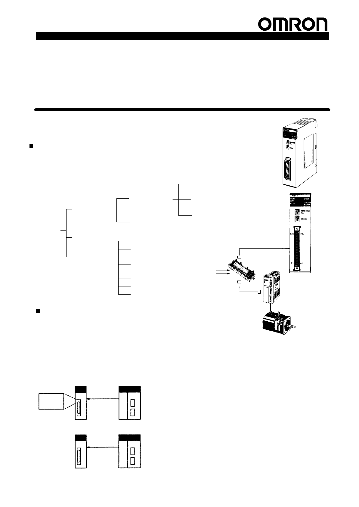
C200HWNC113/NC213/NC413
J System
Configuration
Example
Servo Relay Unit
Pulse Input
Servodriver
Features
Memory Operation and Direct Operation
Operation can be controlled through memory operation, where data for positioning is transferred to the
Position Control Unit and then specified for position
control,
or through direct operation,
tions and speeds are set each time from the CPU Unit.
Combining
these methods is also possible, allowing a
Position Control Unit to perform flexible positioning
operations ranging from easy to complicated.
Memory Operation
Position data
Speed data
Direct Operation
“Programmable Controller” is abbreviated as “PC” in these
Position Control Unit
Data transfer bits
Start sequence No.
specification
Position Control Unit
Data transfer bits
Position data
Speed data
Direct start
command
where target posi
CPU Unit
CPU Unit
-
Specification Sheets.
Servomotor
Various Basis Functions
The C200HW-NC113, C200HW-MC213, and C200HW-413 sup-
various basic functions, such
port
ing, speed controls, jogging, teaching, overrides (speed coefficients), backlash compensation, present position changes, zone
settings,
and deceleration stops.
as origin searches, interrupt feed
Enhanced Functions
The C200HW-NC113, C200HW-MC213, and C200HW-413 support the following functions that the previous models (C200HNC211
and C200H-NC1
•
Direct operation is possible.
12) do not support.
• S-curve acceleration/declaration is possible in addition to
trapezoidal
•
Speed control is possible.
•
Backlash compensation speed can be specified.
acceleration/declaration.
• Forced intervention is possible (specified position data can be
forcibly
executed).
•
Flash memory operation is possible.
-
1
Position Control Unit
CS , C 00 / G/ ,
C00 Seca /OU
use a u d e o
PC
e
words
Product Specifications
Compact Size
The
single-axis, two-axis, and four-axis models are all one compact
size.
Special Support Software for CS1-Series and
C200HX/HG/HE PCs)
Special
Support
dows
95, allows the user to easily create
tion Control Unit. It can also be used for writing data to the PCU,
data from the PCU, saving data, and printing data.
reading
Software, the SYSMAC-NCT
various data for the Posi
, which runs on Win
Models
Applicable PCs
CS1, C200HX/HG/HE,
C200HS, and C200H
s
Support Software (Sold Separately)
Name System
SYSMAC-NCT
Connecting
Cable
Unit classification
C200H Special I/O Unit
Personal computer: IBM AT or
compatible
Operating system: Windows 95
Minimum memory: 16 MB
A
vailable disk space: 10 MB min.
For connecting the RS-232C port on
the CPU Unit
Number of control axes
1 axis
2 axes
4 axes C200HW-NC413
requirements
Easy Data Transfer
Position
data used for
Position Control Unit by using the NC Support Software (for
CS1-Series
the
structions (for CS1-Series and C200HX/HG/HE PCs only).
-
ROM Operation by Flash Memory
Position
memory in the Position Control Unit. It is retained even when the
power
and C200HX/HG/HE PCs only), data transfer bits, and
Intelligent I/O W
data used for memory operation can be stored in the flash
is turned OFF
Pulse-train input driver or
stepping motor driver
Applicable PCs
CS1-Series and
C200HX/HG/HE
PCs only
(Cannot be used
with C200H or
C200HS PCs.)
2.0 m, 5.0 m
memory operation can be transferred to the
rite (IOWR) and Intelligent I/O Read (IORD)
. So, there is no need
Controlled driver
Specifications Model
Creating
positioning data
and parameter
data, transferring
data to the Unit,
writing data to
the flash
memory
printing Unit
status monitor
data, positioning
data, and
parameter data
for battery maintenance.
Model number
C200HW-NC113
C200HW-NC213
WS01-NCTF1-E
, and
XW2Z-jjjj
(For details, refer
to
parts.)
j optional
in
-
Specifications
Item
C200HW-NC113 C200HW-NC213 C200HW-NC413
Applicable PCs CS1-Series, C200HX/HG/HE, C200HS, C200H
Unit classification
Mounting location
Maximum number of Units
that can be mounted
Unit numbers
Data
exchange
area with
CPU Unit
Controlled driver
Control
Control unit
Words
allocated in
the Special
I/O Unit Area
DM area
words
allocated to
Special I/O
Units
Control
system
Number of
control axes
C200H Special I/O Unit
CPU Rack, C200H Expansion I/O Rack, CS1 Expansion Rack, SYSMAC BUS Remote I/O Slave Unit
16 or 10 Units depending on the CPU Unit model (refer to
Connectable CPU Unit Models
0 to F or 0 to 9 depending on the CPU Unit model (refer to
Connectable CPU Unit Models
5 words/Unit
CPU Unit →
Position Control Unit → CPU Unit: Status (positioning completed, present position, etc.)
100 words/Unit
CPU Unit →
mode selection, start speed, origin search speed, acceleration/deceleration time, etc.)
Pulse-train input type Servodriver or stepping motor driver
Open-loop control by pulse train output (automatic trapezoidal or S-curve acceleration/deceleration)
1 axis 2 axes 4 axes
Pulse
Position Control Unit: Operating commands (sequence numbers, start, origin search, etc.)
Position Control Unit: Common parameters and axis parameters (I/O selection, operation
).
).
10 words/Unit 20 words/Unit
Specifications
8 or 5 Units depending on the
CPU Unit model (refer to
Connectable CPU Unit Models
0 to 8, or 0 to 8 and A to E
depending on the CPU Unit
model (refer to
CPU Unit Models
Connectable
).
).
2

Product Specifications
os o g o e a o s
os o s
S eeds
and
Item SpecificationsItem
Positioning
Positions
Speeds
Acceleration
and
deceleration
times
operations
Independent 1 axis
Linear
interpolation
Speed control
Interrupt
feeding
Range
Data items
Range
Data items
Range
Data items
T
wo types: Memory operation and direct operation
Memory operation: T
Control Unit beforehand, and executes positioning in ascending order of sequence numbers by
specifying the start sequence number from the CPU Unit.
Completion code of each sequence for memory operation: Independent, automatic, continuous, bank
end, speed control (continuous output), or interrupt feeding (continuos output with positioning) can be
specified.
Direct operation: W
executes positioning by outputting the data to the Position Control Unit through I/O refresh.
Speed control and interrupt feeding are also possible.
– 2 axes max. 4 axes max.
1 axis
1 axis
–9,999,999 to 9,999,999 pulses
100/axis
1 pps to 500 Kpps
100/axis
0 to 250 s, until maximum speed is reached.
9/axis for acceleration and deceleration each.
Position Control Unit
C200HW-NC413C200HW-NC213C200HW-NC113
ransfers sequence data such as position data and speed data to the Position
rites position data and speed data to the specified area in the CPU Unit and
2 independent axes 4 independent axes
2 independent axes 4 independent axes
2 independent axes 4 independent axes
3

Position Control Unit
Item SpecificationsItem
Functions
Origin search
Origin search
operation
mode
Jogging
Dwell times
Acceleration/
deceleration
curves
Zones
Software limit
Backlash
compensation
Teaching
Forced
intervention
Deceleration
stop
Present
position
change
Override
Pulse output
prohibited
Data transfer
(data
read/write)
Data saving
Product Specifications
C200HW-NC413C200HW-NC213C200HW-NC113
Origin proximity input signal: selectable (absent, N.O. or N.C. contact).
Origin input signal: selectable (N.O. or N.C. contact)
Origin compensation: –9,999,999 to 9,999,999 pulses
Origin search speed: High-speed or proximity-speed can be set.
Origin search method: May be set to stop upon origin input signal after proximity input signal has turned
ON, to stop upon origin input signal after proximity input signal has turned OFF
signal without using proximity input signal, or to stop upon origin input signal after limit input signal has
turned OFF
0
(Mode 0)
1
(Mode 1)
2
(Mode 2)
3
(Mode 3)
Jogging can be executed at a specified speed.
19/axis can be set from 0 to 9.99 s (unit: 0.01 s).
T
rapezoidal or S-curve (Can be set separately for each axis.)
Zone Flag turns ON when present position is within a specified zone. Three zones can be set for each
axis.
Can be set within a range of –9,999,999 to 9,999,999 pulses.
0 to 9,999 pulses. Compensation speed can also be set.
With a command from the CPU Unit, the present position can be taken as the position data.
Stops the active sequence and executes the specified sequence No. (V
only)
The ST
time.
The PRESENT POSITION CHANGE command can be used to change the present position to a
specified value.
When the override enabling command is executed during positioning, the target speed is changed by
applying the override coef
Prohibits pulse output when emergency stop, CW limit, CCW limit, or CW/CCW software limit input
turns ON.
V
arious data can be transferred to the memory in the Position Control Unit, using either of the following
methods:
1) Data transfer bits
2) Intelligent I/O W
C200HX/HG/HE PCs only)
3) SYSMAC-NCT Support Software (for CS1 Series and C200HX/HG/HE PCs only)
V
arious data can be saved in the internal flash memory
If data is saved, the Position Control Unit can be operated using the saved data when it is turned ON or
restarted. There is no need to transfer data to the Unit each time.
Note: Flash memory life expectancy: 100,000 times (reads/writes)
.
N.O. = Normally open
N.C. = Normally closed
Stepping motors are used and external sensor signals are used as origin input signals. In
this case, error counter reset output and origin-adjustment command output can be used
as general-purpose outputs.
Servodrivers are used and encoder phase-Z signals are used as origin input signals. The
Servodriver’
Servodrivers are used and encoder phase-Z signals are used as origin input signals. The
Servodriver’
Servodrivers such as OMRON H-Series and M-Series are used. The Servodriver’s
origin-adjustment command is used to complete origin search. The Servodriver
positioning completed signals are used.
OP command causes positioning to decelerate to a stop according to the specified deceleration
s positioning completed signals are not used.
s positioning completed signals are used.
ficient.
rite (IOWR) and Intelligent I/O Read (IORD) instructions (for CS1-Series and
.
, to stop upon origin input
’s
alid during memory operation
4

Product Specifications
( rovided as
C
Item SpecificationsItem
External I/O Inputs
Outputs
Pulse output distribution
period
Self-diagnostic function
Error detection function
Unit number setting switch
LED indicators
Connections on the front
panel
Internal current consumption
(provided from Power Supply
Unit)
Dimensions
W
eight (excluding
connectors)
Standard accessories
Cat. No. W334 (W324 for SYSMAC-NCT Support Software)
Prepare the following inputs for each axis:
CW and CCW limit input signals, origin proximity input signal, origin input signal (see note), emergency
stop input signal, positioning completed signal, interrupt input signal
V
oltage: 24 VDC
Current: 4.3 mA (at 24 V) typ.
ON voltage: 17.4 VDC min.
OFF voltage: 5.0 VDC max.
ON response time: 1 ms max. (0.1 ms max.: Interrupt input)
OFF response time: 1 ms. max.
The following information applies to origin input only
External signal is open-collector signal: Same as above, except for response time (N.O. contact: 0.1 ms
max.; N.C. contact: 1 ms max.)
External signal is line-driver signal: Corresponds to line driver signals equivalent to Am26LS31, except
for response time (N.O. contact: 0.1 ms max.; N.C. contact: 1 ms max.)
Prepare the following outputs for each axis:
Pulse outputs (open collector outputs)
CW/CCW pulses, pulse outputs and direction outputs can be switched.
Either error counter reset or origin-adjustment command outputs can be selected depending on the
mode.
Maximum switching capacity: 30 mA at 4.75 to 26.4 VDC (NPN open collector)
(16 mA: T
Minimum switching capacity: 7 mA at 4.75 to 26.4 VDC (NPN open collector)
Leakage current: 0.1 mA max.
Residual voltage: 0.6 V max.
External power supply:
4 ms
Flash memory check, memory loss check, I/O bus check
Overtravel, CPU error
Rotary switch: Unit number (0 to F) (Dif
CPU Unit Models
Number of indicators: 5 (NC113), 6 (NC213), 8 (NC413)
Show the PCU’
state.
X-axis connector X/Y-axis connector X/Y-axis connector
Use the FCN-361J048-AU Connector (soldered) and the FCN-360C048-D Connector Cover provided.
Also, use OMRON’
300 mA max. at 5 VDC 300 mA max. at 5 VDC 500 mA max. at 5 VDC
130 x 34.5 x 100.5 mm (H x W x D)
The height including the Backplane is 230 mm when the attached connector or OMRON’
Cable is used.
250 g max. 300 g max. 350 g max.
Fujitsu FCN-361J048-AU Connector (soldered) and FCN-360C048-D Connector Cover: 1 set
±10%
erminals with 1.6-kΩ limit resistance)
24 VDC ±10%
C200HW-NC1
C200HW
C200HW
, software limit over
.)
s status such as running state, error state, input signal state, data state, and each axis
s Servodriver Connecting Cables.
13: 30 mA max.
-NC213: 50 mA max.
-NC413: 90 mA max.
, emergency stop
fers depending on the CPU Unit model. Refer to
Position Control Unit
C200HW-NC413C200HW-NC213C200HW-NC113
.
Connectable
,
Z/U-axis connector
s Servodriver
Options (Sold Separately)
Item Specifications Model
Connectors for each axis Soldered
(provided as
standard on this
Unit)
Crimp
number
Soldered connector
Connector cover FCN-360C048-D
Crimp-type housing
Contact FCN-363J-AU/S
Connector cover FCN-360C048-D
FCN-361J048-AU
FCN-363J048
5
Position Control Unit
C
USeesoy
C
d
(T
q
USees
oy
Software Connecting
RS 232C ort on the
Product Specifications
Item Model
The following cables and Servo Relay Units can be used
to connect OMRON’s Servodrivers.
1 axis Connecting
2 axes Connecting
Item Connection port
SYSMAC-NCT Support
Software Connecting
Cable
Connects to the
RS-232C port on the
CPU Unit (in Host Link
Mode).
able H-Series,
Servo Relay Unit
able
Servo Relay Unit
Applicable CPU Units
PC CPU
Position Control Unit C200HW-NC113/NC213 C200HW-NC413
CS1 Series CS1H-CPUjjj
CS1G-CPUjjj
C200HX/HG/HE
C200HS C200HS-CPU01(-j)/21
C200H C200H-CPU01/02/03/11/21/2
C200HE-CPU1
C200HG-CPU33/43 (-ZE)
C200HX-CPU34/44 (-ZE)
C200HG-CPU53/63 (-ZE)
C200HX-CPU54/64 (-ZE)
C200HX-CPU65-ZE/85-ZE
(-j)/31/03/23/33
2/23/31
Unit model
1/32/42 (-ZE)
CPU Racks, Expansion Racks, and SYSMAC BUS
16 (Unit No.: 0 to F) 8 (Unit No.: 0 to 8, A to E)
10 (Unit No.: 0 to 9) 5 (Unit No.: 0 to 8)
16 (Unit No.: 0 to F) 8 (Unit No.: 0 to 8, A to E)
10 (Unit No.: 0 to 9) 5 (Unit No.: 0 to 8)
10 (Unit No.: 0 to 9) 5 (Unit No.: 0 to 8)
Specifications
Applicable
Position Control
Unit
C200HW-NC113 U-Series,
Connects to the above cable.
C200HW-NC213
an
C200HW-NC413
wo
cables are
required for
C200HW-NC413.)
Connects to the above cable. (T
for C200HW
Personal computer Cable length
IBM A
T or compatible
T
otal number of PCUs that can be mounted on
Remote I/O Slave Units (see note).
-NC413.)
Applicable
OMRON
Servodriver
M-Series
UEP-Series only
U-Series,
H-Series,
M-Series
UEP-Series
only
wo Units are required
2.0 m
5.0 m
Cable length
50 cm
100 cm
50 cm
100 cm
50 cm XW2Z-050J-A7
100 cm XW2Z-100J-A7
50 cm
100 cm
number
---
XW2Z-050J-A6
XW2Z-100J-A6
XW2Z-050J-A8
XW2Z-100J-A8
XW2B-20J6-1B
XW2Z-050J-A9
XW2Z-100J-A9
XW2B-40J6-2B
Model
XW2Z-200S-V
XW2Z-500S-V
Unit mounting
restrictions
None
None
None
None
Cannot be mounted in
the two rightmost slots
on the CPU Rack.
Note: Restrictions in Using SYSMAC BUS Remote I/O Slave Units
The
maximum number of C200H Special I/O Units that can be mounted
the
Units as shown below
Units
that can be mounted.
Group A B C D
Units
Maximum number of
Units that can be
mounted in each group
under one Master Unit
Maximum number of
Units that can be
mounted in all groups
. C200H Special I/O Units can be divided into the following four groups according to the maximum number of
ASCII Unit,
High-speed Counter
Unit, Position Control
Unit
(NC111/112/113/213),
Analog I/O Unit, ID
Sensor Unit, Fuzzy
Logic Unit
4 Units 8 Units 6 Units 2 Units
3A + B + 2C + 6D x 12, AND A + B + C + D
High-density I/O Unit,
T
emperature Control
Unit, PID Control Unit,
Heating/Cooling
Control Unit, Cam
Positioner Unit
on a SYSMAC BUS Remote I/O Slave Unit dif
T
emperature Sensor
Unit, Voice Unit
x 8
Position Control Unit
(NC21
1/413), Motion
Control Unit
fers according to
6

Product Specifications
System Configuration
Control System: Open-loop System
Position
Position Control Unit
Control Unit
Connection Configuration
Position Control
Unit
Tachogenerator
Rotary encoder
CPU Unit
Power Supply
Unit
SYSMAC-NCT
Note: The
Position Control Unit does not in
position feedback signals.
put
Pulse output
Servodriver or stepping driver
Servomotor or stepping motor
Item 1-axis 2/4-axis
Connecting
on PCU end
Servo Relay Unit
cable
-
XW2Z-jjjJ-Aj XW2Z-jjjJ-Aj
XW2B-20J6-1B XW2B-40J6-2B
CCW limit input, CW
limit input, origin
proximity input,
emergency stop input,
etc.
Connecting cable on PCU end
Servo Relay Unit
Connecting cable on Servodriver
end
Pulse output
Servodriver
Servomotor
or
Host link
Stepping driver
Stepping motor
+
Item Connection
Connecting cable on
Servodriver end
to U-Series
XW2Z-jjj
J-B1
Connection
to M-Series
XW2Z-jjj
J-B2
Connection
to H-Series
XW2Z-jjj
J-B3
+
Servodriver U-Series M-Series H-Series
R88D-UPjjj R88D-MTjjj R88D-Hjjj
7
Position Control Unit
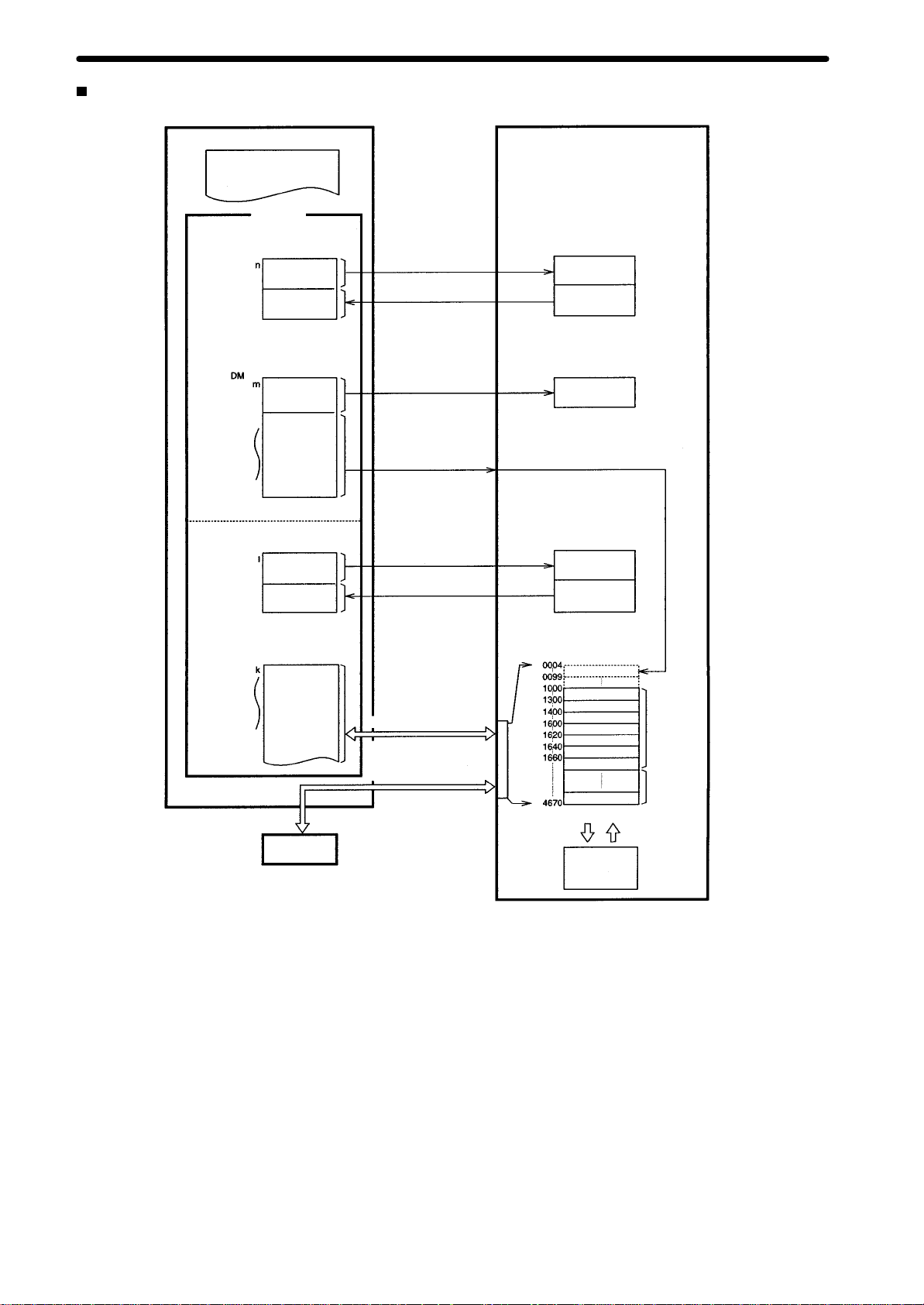
Exchanging Data
CPU Unit
Ladder program
MOV
I/O memory
IR/CIO area (operating memory area)
n+7
n+8
n+19
DM area (parameter area)
m+3
m+4
m+99
, LD, etc.
Operation
commands
Status inputs
Common
parameters
Axis
parameters
I/O refresh
At power-up or restart
At power-up or restart
Product Specifications
Position Control Unit (C200HW-NC413)
Command
interpretation
Status
such as
positioning completed
or present position
Common
parameters
DM or EM area
I+25
I+26
I+33
Operating data area
Data
transfer data,
operation data, etc.
Status inputs
Data transfer area
Data for memory
operation
SYSMAC-NCT
I/O refresh
When data transfer
commands are executed
When IOWR or IORD
is executed
When data transfer
commands are executed
Settings analysis
and execution
Status such as
I/O signals and
error codes
Internal memory
Address
Saving data Startup restart
Data area
Axis parameters
Sequence data
Speed data
Position data
Acceleration time data
Deceleration time data
Dwell time data
Zone data
Flash memory
Data for
X axis
Data for Y
to U axes
8

Product Specifications
Components
C200HW-NC413
LED indicators
Show the PCU’s
operating status.
Position Control Unit
C200HW-NC213 C200HW-NC113
X/Y axis connector
(see note)
Connects stepping
motor driver or
Servodriver. (2-axis
control)
LED Indicators
Name Color Status Explanation
RUN Green
ERR Red
SENS Red
DATA Red
X Orange
Y Orange
Z Orange
U Orange
Unit number
setting switch
Set the unit number
for the PCU (0 to F).
Z/U axis connector
(see note)
Connects stepping
motor driver or
Servodriver. (2-axis
control)
Lit
Not
lit
Lit
/ flashing
Not
lit
Lit
Flashing
Not
lit
Flashing
Lit
Not
lit
Lit
Flashing
Not
lit
Lit
Flashing
Not
lit
Lit
Flashing
Not
lit
Lit
Flashing
Not
lit
X-,
Y-axis
connect
or
Lit
during normal operation.
X-axis connector (see note)
Note: The Unit is provided with a Fujitsu
FCN-361J048-AU Connector (soldered) and
FCN-360C048-D Connector Cover.
Hardware error, or PC notified of PCU error.
An error has occurred.
No error has occurred.
Either a CW/CCW limit signal or an emergency stop
input signal is being input. At this time the LED indicator
for the relevant axis (X to U) will flash.
Either a parameter loss, a data loss, or an operating
data area designation error has occurred.
None of the above has occurred.
The check of all data (parameters, positions, etc.)
following power up shows that data is lost or corrupted.
Data is incorrect (e.g., the parameters or positions
transferred are out of the permissible range). At this time
the LED indicator for the relevant axis (X to U) will flash.
None of the above has occurred.
Pulses are being output to the X axis (either forward or
reverse).
An error has occurred, such as incorrect cable type for
the X axis or faulty data.
None of the above has occurred.
Pulses are being output to the Y axis (either forward or
reverse).
An error has occurred, such as incorrect cable type for
the Y axis or faulty data.
None of the above has occurred.
Pulses are being output to the Z axis (either forward or
reverse).
An error has occurred, such as incorrect cable type for
the Z axis or faulty data.
None of the above has occurred.
Pulses are being output to the U axis (either forward or
reverse).
An error has occurred, such as incorrect cable type for
the U axis or faulty data.
None of the above has occurred.
9

Position Control Unit
External I/O Connectors
Connector Pin Numbers
Outline of connector (rear
side)
Product Specifications
X/Y axis Z/U axis X/Y axis X axis
C200HW-NC413 C200HW-NC213 C200HW-NC113
Connector
Pin
No.
A1 IN
A2 IN
A3 -A4 -A5 OUT
A6 OUT
A7 OUT
A8 OUT
A9 -A10 OUT
A11 OUT
A12 IN
A13 -A14 IN
A15 IN
A16 IN
A17 -A18 -A19 IN
A20 IN
A21 IN
A22 IN
A23 IN
A24 IN
Pin number marks
(Viewed from soldered side)
Pin Arrangement for X and Z Axes
I/O Name
Output power supply
Output GND, 24 VDC
Not used
Not used
CW pulse output
CW pulse/pulse output with 1.6 KΩ resistance
CCW pulse/direction output
CCW pulse/direction output with 1.6 KΩ resistance
Not used
Error counter reset output Origin-adjustment
command output
Error counter reset output with 1.6 KΩ resistance
Origin-adjustment command output with 1.6 K
resistance
Positioning completed input signal
Not used
Origin common
Origin input signal (24 V)
Origin input signal (5 V)
Not used
Not used
Interrupt input signal
Emergency stop input signal
Origin proximity input signal
CW limit input signal
CCW limit input signal
Input common
, 24 VDC
Connector
Pin
B1 IN
B2 IN
B3 -B4 -B5 OUT
B6 OUT
B7 OUT
B8 OUT
B9 -B10 OUT
Ω
B11 OUT
B12 IN
B13 -B14 IN
B15 IN
B16 IN
B17 -B18 -B19 IN
B20 IN
B21 IN
B22 IN
B23 IN
B24 IN
Pin Arrangement for Y and U Axes
No.
I/O Name
Output power supply
Output GND, 24 VDC
Not used.
Not used.
CW pulse output
CW pulse/pulse output with 1.6 KΩ resistance
CCW pulse/direction output
CCW pulse/direction output with 1.6 KΩ resistance
Not used.
Error counter reset output Origin-adjustment
command output
Error counter reset output with 1.6 KΩ resistance
Origin-adjustment command output with 1.6 K
resistance
Positioning completed input signal
Not used.
Origin common
Origin input signal (24 V)
Origin input signal (5 V)
Not used.
Not used.
Interrupt input signal
Emergency stop input signal
Origin proximity input signal
CW limit input signal
CCW limit input signal
Input common
, 24 VDC
Ω
10
Product Specifications
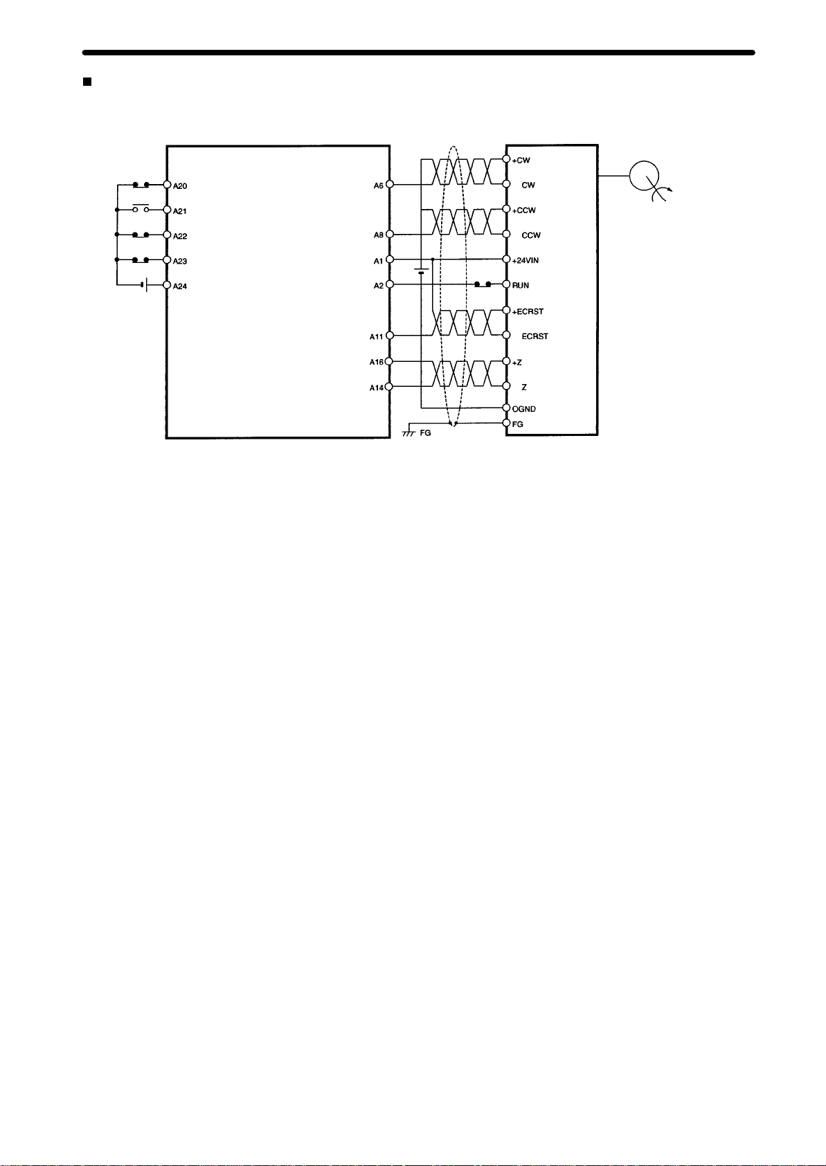
External Connection Diagram
This
example shows the use of a Servodriver
as
origin input signals.
with encoder phase-Z
OMRON R88D-UPjjj
Servodriver
Position Control Unit
R88M-U Servomotor
–
+
24 VDC
Note: N.O.
Emergency stop input
Origin proximity input (see note)
CW limit input (see note)
CCW limit input (see note)
Input common
Error counter reset output,
origin-adjustment command output
or N.C. contact can be selected
using axis parameters.
CW pulse output
CCW pulse output/
direction output with
1.6 KΩ resistance
24-V power supply
for output
24 V GND for output
Origin input signal (5 V)
Origin common
24 VDC
–
–
+
–
N.C.
contact
–
–
11

Position Control Unit
Product Specifications
Combinations of Servo Relay Units, Servodrivers, and Position Control Units
Connecting cable on
Servodriver end
(See note 2)
Servodriver
Position Control Unit
Single-axis Position
Control Unit for C200HS
C200HW-NC113
2/4-axis Position Control
Unit for C200HS
C200HW-NC213/413
Connecting cable on
PCU end
Connecting cable
for C200H-NC113
XW2Z-jjjJ-Aj
Connecting cable for
C200H-NC213/413
(see note 1)
XW2Z-jjjJ-Aj
Note: 1. Two
4-axis PCUs.
Servo Relay Unit
Servo Relay Unit
for C200H-NC113
XW2B-20J6-1B
Servo Relay Unit for
C200H-NC213/413
(see note 1)
XW2B-40J6-2B
cables or Units are requIred for
Connecting cable
for U-Series
XW2Z-jjjJ-B1
(See note 2)
Connecting cable
for M-Series
XW2Z-jjjJ-B2
(See note 2)
U-Series Servodriver
R88D-UPjjj
M-Series Servodriver
R88D-MTjjj
Connecting cable
for H-Series
XW2Z-jjjJ-B3
2. When
the Servodriver is combined with the C200HW
connecting
cables are required on the Servodriver end. When the Servo
driver is combined with the C200HW-NC413 (4-axis), four connecting
cables are required on the Servodriver end.
H-Series Servodriver
R88D-Hjjj
-NC213 (2-axis), two
-
12

Product Specifications
Connection Diagram for Position Control Unit
and Servo Relay Unit
XW2Z-jjjJ-A6/A8
Connecting
For C200HW-NC113
Power supply for output
Error
origin-adjustment command output
Positioning completed input
Emergency stop input
Origin input (24 V)
XW2Z-jjjJ-A7/A9
Connecting
For C200HW-NC213/NC413
Cable:
24-V GND for output
CCW
pulse output/direction
output with 1.6 KΩ resistance
CW pulse output with
1.6 KΩ resistance
counter reset output,
Origin input (5 V)
Origin common
Input common
Origin proximity input
CCW limit input
CW limit input
Interrupt input
F.G. (crimp terminal)
(Lead: 500 mm)
Cable:
1 axis, U/H/M-Series Servodriver 1 axis, UEP-Series Servodriver
Position Control
Unit NC113
Connecting cable
XW2Z-jjjJ-A6
Servo Relay Unit
XW2B
24 V
GND
+ CCW
– CCW
+ CW
– CW
+ ECRST
– ECRST
+ Z
– Z
24 V
INP
Origin proximity
CCW limit
CW limit
External interrupt
Emergency stop input
FG
Origin input (24 V)
Origin common
F.G. (crimp terminal)
(Lead: 500 mm)
Position Control
Unit NC113
Position Control Unit
Connecting cable
XW2Z-jjjJ-A8
Servo Relay Unit
XW2B
24 V
GND
+ CCW
– CCW
+ CW
– CW
+ ECRST
– ECRST
HRET
+ Z
– Z
24 V
INP
Origin proximity
CCW limit
CW limit
External interrupt
Emergency stop input
Origin input (24 V)
Origin common
FG
24-V power supply for output
24-V GND for output
CCW pulse output/direction
output with 1.6 KΩ resistance
CW pulse output with
1.6 KΩ resistance
Error counter reset output,
origin-adjustment command
output
X-axis emergency stop input
CCW pulse output/direction
output with 1.6 KΩ resistance
Positioning completed input
Y-axis emergency stop input
Origin input (5 V)
Origin common
Input common
Interrupt input
Origin proximity input
Positioning completed input
CCW limit input
CW limit input
CW limit input
CW pulse output with
1.6 KΩ resistance
Error counter reset
output, origin-adjustment
command output
Origin input (5 V)
Origin common
CCW limit input
CW limit input
Origin proximity input
Interrupt input
F.G. (crimp terminal)
(Lead: 500 mm)
2 axes, U/H/M-Series Servodriver
Position Control Unit
NC213/NC413
Connecting cable
XW2Z-jjjJ-A7
Servo Relay Unit
XW2B
24 V
GND
+ CCW
– CCW
+ CW
– CW
+ ECRST
– ECRST
HRET
+ Z
– Z
24 V
External interrupt
Origin proximity
INP
CCW limit
CW limit
Emergency stop input
+ CCW
– CCW
+ CW
– CW
+ ECRST
– ECRST
HRET
+ Z
– Z
CCW limit
CW limit
Origin proximity
External interrupt
INP
FG
Origin input (24 V)
F.G. (crimp terminal)
(Lead: 500 mm)
2 axes, UEP-Series Servodriver
Position Control Unit
NC213/NC413
Connecting cable
XW2Z-jjjJ-A9
Servo Relay Unit
XW2B
24 V
GND
+ CCW
– CCW
+ CW
– CW
+ ECRST
– ECRST
HRET
+ Z
– Z
24 V
External interrupt
Origin proximity
INP
CCW limit
CW limit
Emergency stop input
+ CCW
– CCW
+ CW
– CW
+ ECRST
– ECRST
HRET
+ Z
– Z
CCW limit
CW limit
Origin proximity
External interrupt
INP
Origin input (24 V)
FG
13
Position Control Unit
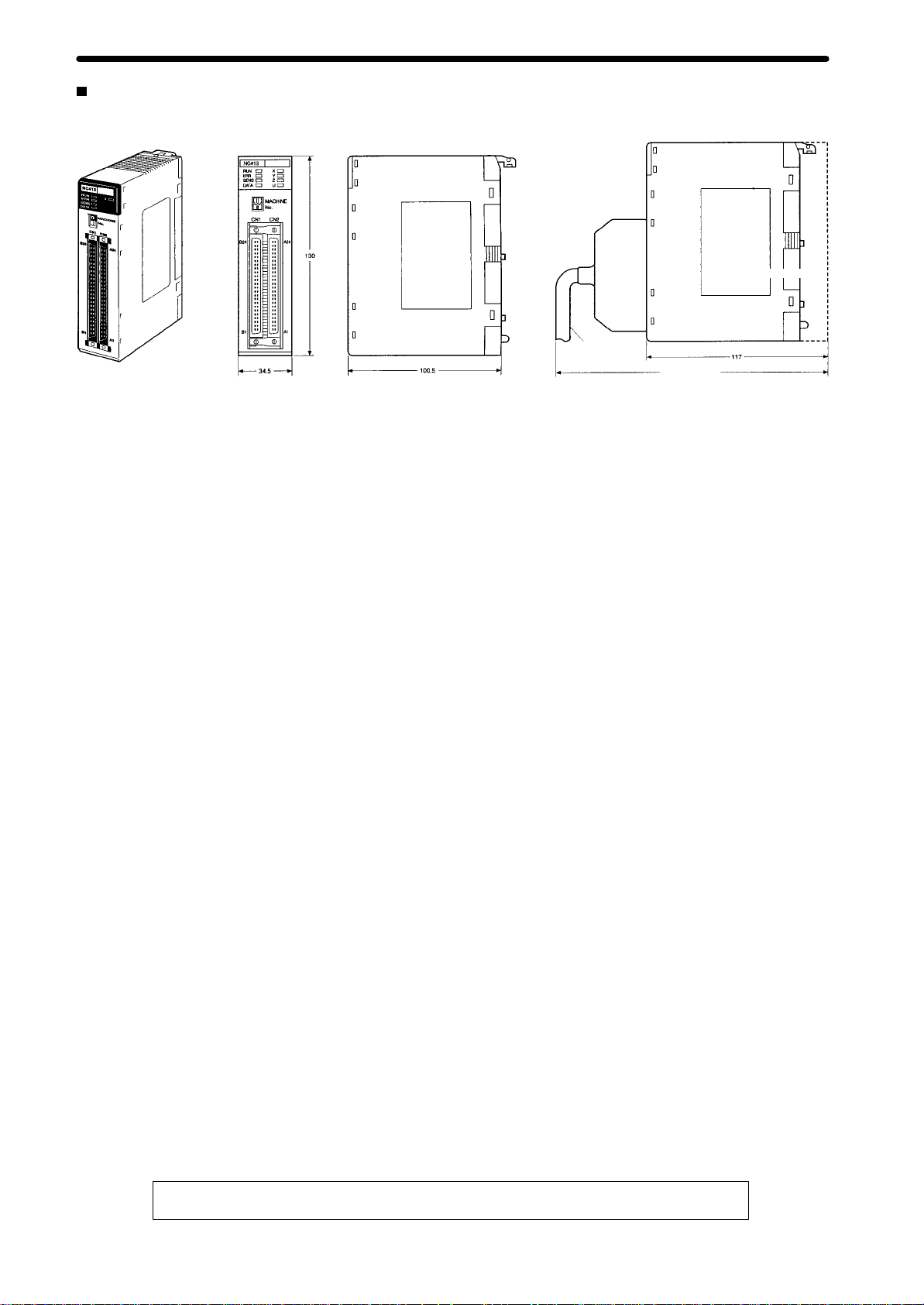
Dimensions (Unit: mm)
Product Specifications
Connection
cable
Mounted
Approx. 230
Dimensions
Backplane
14
ALL DIMENSIONS SHOWN ARE IN MILLIMETERS.
To
convert millimeters into inches, multiply by 0.03937. T
o convert grams into ounces, multiply by 0.03527.

OMRON Corporation
Systems Components Division
66 Matsumoto
Mishima-city
, Shizuoka 41
1-851
Japan
T
el: (81)559-77-9633
Fax: (81)559-77-9097
Regional Headquarters
OMRON EUROPE B.V.
W
egalaan 67-69, NL-2132 JD Hoofddorp
1
The Netherlands
T
el: (31)2356-81-300/Fax: (31)2356-81-388
OMRON ELECTRONICS, INC.
1 East Commerce Drive, Schaumburg, IL 60173
U.S.A.
T
el: (1)847-843-7900/Fax: (1)847-843-8568
OMRON ASIA PACIFIC PTE. LTD.
83 Clemenceau Avenue,
#1
1-01, UE Square,
Singapore 239920
T
el: (65)835-301
1/Fax: (65)835-271
1
Authorized Distributor:
Note:
Specifications subject to change without notice.
Cat.
No. R060-E1-1
Printed in Japan
0100-0.7M
 Loading...