

Page 1
C200H-TV| W240-E3-1 Cat. No.
Temperature Control Units
OMRON
SYSMAC -SystemC200H
Presented by - MRO Electric and Supply Company, Inc.
ForProduct Needs:
Email: sales@MROELECTRIC.COM
Call: 1-800-691-8511 Fax: 919-415-1614
http://www.MROELECTRIC.com/
OMRON System C200H MRO ELECTRIC & SUPPLY Company mroelectric.com
Page 2
C200H-TV
Heat/Cool
Temperature Control Unit
Operation Manual
Cat. No. W240-E3-1
Page 3

Notice:
OMRON products are manufactured for use according to proper procedures by a qualified operator
and only for the purposes described in this manual.
The following conventions are used to indicate and classify precautions in this manual. Always heed
the information provided with them. Failure to head precautions can result in injury to people or damage to the product.
DANGER! Indicates information that, if not heeded, is likely to result in loss of life or serious
injury.
WARNING Indicates information that, if not heeded, could possibly result in loss of life or
serious injury.
Caution Indicates information that, if not heeded, could result in relative serious or minor
injury, damage to the product, or faulty operation.
OMRON Product References
All OMRON products are capitalized in this manual. The word “Unit” is also capitalized when it refers
to an OMRON product, regardless of whether or not it appears in the proper name of the product.
The abbreviation “Ch,” which appears in some displays and on some OMRON products, often means
“word” and is abbreviated “Wd” in documentation in this sense.
The abbreviation “PC” means Programmable Controller and is not used as an abbreviation for anything else.
Visual Aids
The following headings appear in the left column of the manual to help you locate different types of
information.
OMRON, 1998
All rights reserved. No part of this publication may be reproduced, stored in a retrieval system, or transmitted, in any
form, or by any means, mechanical, electronic, photocopying, recording, or otherwise, without the prior written permission of OMRON.
No patent liability is assumed with respect to the use of the information contained herein. Moreover, because OMRON is
constantly striving to improve its high-quality products, the information contained in this manual is subject to change
without notice. Every precaution has been taken in the preparation of this manual. Nevertheless, OMRON assumes no
responsibility for errors or omissions. Neither is any liability assumed for damages resulting from the use of the information contained in this publication.
Note Indicates information of particular interest for efficient and convenient operation
of the product.
1, 2, 3...
1. Indicates lists of one sort or another, such as procedures, checklists, etc.
v
Page 4

TABLE OF CONTENTS
MROELECTRIC.COM
SECTION 1
System Configuration and Features 1. . . . . . . . . . . . . . . . .
1-1 Features 2. . . . . . . . . . . . . . . . . . . . . . . . . . . . . . . . . . . . . . . . . . . . . . . . . . . . . . . . . . . . . . .
1-2 Basic System Configuration 3. . . . . . . . . . . . . . . . . . . . . . . . . . . . . . . . . . . . . . . . . . . . . . . .
SECTION 2
Connections and Settings 5. . . . . . . . . . . . . . . . . . . . . . . . . .
2-1 Nomenclature 6. . . . . . . . . . . . . . . . . . . . . . . . . . . . . . . . . . . . . . . . . . . . . . . . . . . . . . . . . . .
2-2 Switch Settings 7. . . . . . . . . . . . . . . . . . . . . . . . . . . . . . . . . . . . . . . . . . . . . . . . . . . . . . . . . .
2-3 Wiring 10. . . . . . . . . . . . . . . . . . . . . . . . . . . . . . . . . . . . . . . . . . . . . . . . . . . . . . . . . . . . . . . . .
2-3-1 Input Wiring 10. . . . . . . . . . . . . . . . . . . . . . . . . . . . . . . . . . . . . . . . . . . . . . . . . . . . .
2-3-2 Output Wiring 13. . . . . . . . . . . . . . . . . . . . . . . . . . . . . . . . . . . . . . . . . . . . . . . . . . .
2-3-3 Data Setting Console Cables 17. . . . . . . . . . . . . . . . . . . . . . . . . . . . . . . . . . . . . . . .
SECTION 3
Data Setting Console Operation 19. . . . . . . . . . . . . . . . . . . .
3-1 Operating Procedure 20. . . . . . . . . . . . . . . . . . . . . . . . . . . . . . . . . . . . . . . . . . . . . . . . . . . . . .
3-2 Data Flow 21. . . . . . . . . . . . . . . . . . . . . . . . . . . . . . . . . . . . . . . . . . . . . . . . . . . . . . . . . . . . . .
3-3 Nomenclature and Features 22. . . . . . . . . . . . . . . . . . . . . . . . . . . . . . . . . . . . . . . . . . . . . . . .
3-3-1 Nomenclature 22. . . . . . . . . . . . . . . . . . . . . . . . . . . . . . . . . . . . . . . . . . . . . . . . . . . .
3-3-2 Features 23. . . . . . . . . . . . . . . . . . . . . . . . . . . . . . . . . . . . . . . . . . . . . . . . . . . . . . . .
3-4 Parameter Displays and Settings 24. . . . . . . . . . . . . . . . . . . . . . . . . . . . . . . . . . . . . . . . . . . .
3-4-1 Table of Parameters 24. . . . . . . . . . . . . . . . . . . . . . . . . . . . . . . . . . . . . . . . . . . . . . .
3-4-2 How to Display and Set Parameter Data 26. . . . . . . . . . . . . . . . . . . . . . . . . . . . . . .
SECTION 4
PC Memory Allocation and Programming 35. . . . . . . . . . .
4-1 Memory Allocation 36. . . . . . . . . . . . . . . . . . . . . . . . . . . . . . . . . . . . . . . . . . . . . . . . . . . . . .
4-1-1 Memory Allocation Table 37. . . . . . . . . . . . . . . . . . . . . . . . . . . . . . . . . . . . . . . . . .
4-1-2 Memory Contents 38. . . . . . . . . . . . . . . . . . . . . . . . . . . . . . . . . . . . . . . . . . . . . . . . .
4-1-3 Table of Commands 41. . . . . . . . . . . . . . . . . . . . . . . . . . . . . . . . . . . . . . . . . . . . . . .
4-2 Data Flow 43. . . . . . . . . . . . . . . . . . . . . . . . . . . . . . . . . . . . . . . . . . . . . . . . . . . . . . . . . . . . . .
4-3 Programming 43. . . . . . . . . . . . . . . . . . . . . . . . . . . . . . . . . . . . . . . . . . . . . . . . . . . . . . . . . . .
4-3-1 Example with SW2-1 in the Fixed Position 43. . . . . . . . . . . . . . . . . . . . . . . . . . . .
4-3-2 Example 1: Write with SW2-1 in the Normal Position 44. . . . . . . . . . . . . . . . . . . .
4-3-3 Example 2: Read with SW2-1 in the Normal Position 47. . . . . . . . . . . . . . . . . . . .
4-3-4 Operation Timing 50. . . . . . . . . . . . . . . . . . . . . . . . . . . . . . . . . . . . . . . . . . . . . . . . .
SECTION 5
Troubleshooting 53. . . . . . . . . . . . . . . . . . . . . . . . . . . . . . . . .
Error Detection 54. . . . . . . . . . . . . . . . . . . . . . . . . . . . . . . . . . . . . . . . . . . . . . . . . . . . . . . . . . . . . . .
A Specifications 57. . . . . . . . . . . . . . . . . . . . . . . . . . . . . . . . . . . . . . . . . . . . . . . . . . . . . . . . . . . . . .
B Sensor Temperature Measurement Ranges 59. . . . . . . . . . . . . . . . . . . . . . . . . . . . . . . . . . . . . . .
C Heater Burnout Detection 61. . . . . . . . . . . . . . . . . . . . . . . . . . . . . . . . . . . . . . . . . . . . . . . . . . . .
D Parameters and Key Operations 67. . . . . . . . . . . . . . . . . . . . . . . . . . . . . . . . . . . . . . . . . . . . . . . .
Index 69. . . . . . . . . . . . . . . . . . . . . . . . . . . . . . . . . . . . . . . . . .
Revision History 71. . . . . . . . . . . . . . . . . . . . . . . . . . . . . . . . .
vii
Page 5

About this Manual:
MROELECTRIC.COM
This manual describes the installation and operation of the C200H-TV Heat/Cool Temperature
Control Unit and includes the sections described below. Also briefly described is the basic operation and
installation of the C200H-DSC01 Data Setting Console.
Please read this manual carefully and be sure you understand the information provided before attempting
to install and operate the Heat/Cool Temperature Control Unit and Data Setting Console.
Section 1
ration.
Section 2
Unit.
Section 3
tings and displays.
Section 4
programming procedures and examples are also provided.
Section 5
The five Appendices provide references dealing with specifications, sensor temperature measurement
ranges, heater burnout detection, and dimensions, and a table of Data Setting Console key operations.
provides Heat/Cool Temperature Control Unit features and describes its basic system configu-
provides information on the connections and settings of the Heat/Cool Temperature Control
provides the basic operating procedures of the Data Setting Console including parameter set-
provides the C200H PC’s memory allocation for the Heat/Cool Temperature Control Unit. Basic
provides possible errors and error remedies.
WARNING Failure to read and understand the information provided in this manual may result in
personal injury or death, damage to the product, or product failure. Please read each
section in its entirety and be sure you understand the information provided in the section
and related sections before attempting any of the procedures or operations given.
ix
Page 6

SECTION 1
MROELECTRIC.COM
System Configuration and Features
This section provides Heat/Cool Temperature Control Unit features and describes its basic system configuration.
1-1 Features 2. . . . . . . . . . . . . . . . . . . . . . . . . . . . . . . . . . . . . . . . . . . . . . . . . . . . . . . . . . . . . . . .
1-2 Basic System Configuration 3. . . . . . . . . . . . . . . . . . . . . . . . . . . . . . . . . . . . . . . . . . . . . . . . .
1
Page 7

Features Section 1-1
MROELECTRIC.COM
1-1 Features
The Heat/Cool Temperature Control Unit measures the temperature of an object
with a connected temperature sensor (thermocouple or platinum resistance
thermometer) and controls the temperature according to preset parameters.
Advanced PID Control
Stable temperature control is achieved using advanced PID control and an autotuning feature.
ON/OFF control can also be selected.
Units Available According to Type of Temperature Sensor
Two types of Temperature Control Unit are available, according to the temperature sensor used. The C200H-TV00 uses a thermocouple, and the
C200H-TV10 uses a platinum resistance thermometer.
Two Heat/Cool Control Loops with a Single Unit
Two heating and cooling control loops are possible with one Unit.
Comprehensive Output Specifications
Three types of output specification versions are available: C200H-TV1 for
transistor output, C200H-TV2 for voltage output, and C200H-TV3 for
current output.
Heater Burnout Detection
A Current Transformer (with a detection current range of 0.1 to 49.9 A and a minimum detection current difference of 2.5 A) can be connected to each of the two
control loops to facilitate rapid heater burnout detection and prompt correction of
problems.
Eight Banks of Data Settings
Eight data values such as set point (SP) and alarm set values can be preset in
eight data banks for easy selection.
Data Input and Display
The C200H-DSC01 Data Setting Console (sold separately) is used to input data
and to display process values (PV) and set values (SV).
The easy-to-read display can be panel-mounted.
User Programs Allow Reading and Writing of Data
Data can be set and retrieved by means of C200H user programs.
2
Page 8
Basic System Configuration
MROELECTRIC.COM
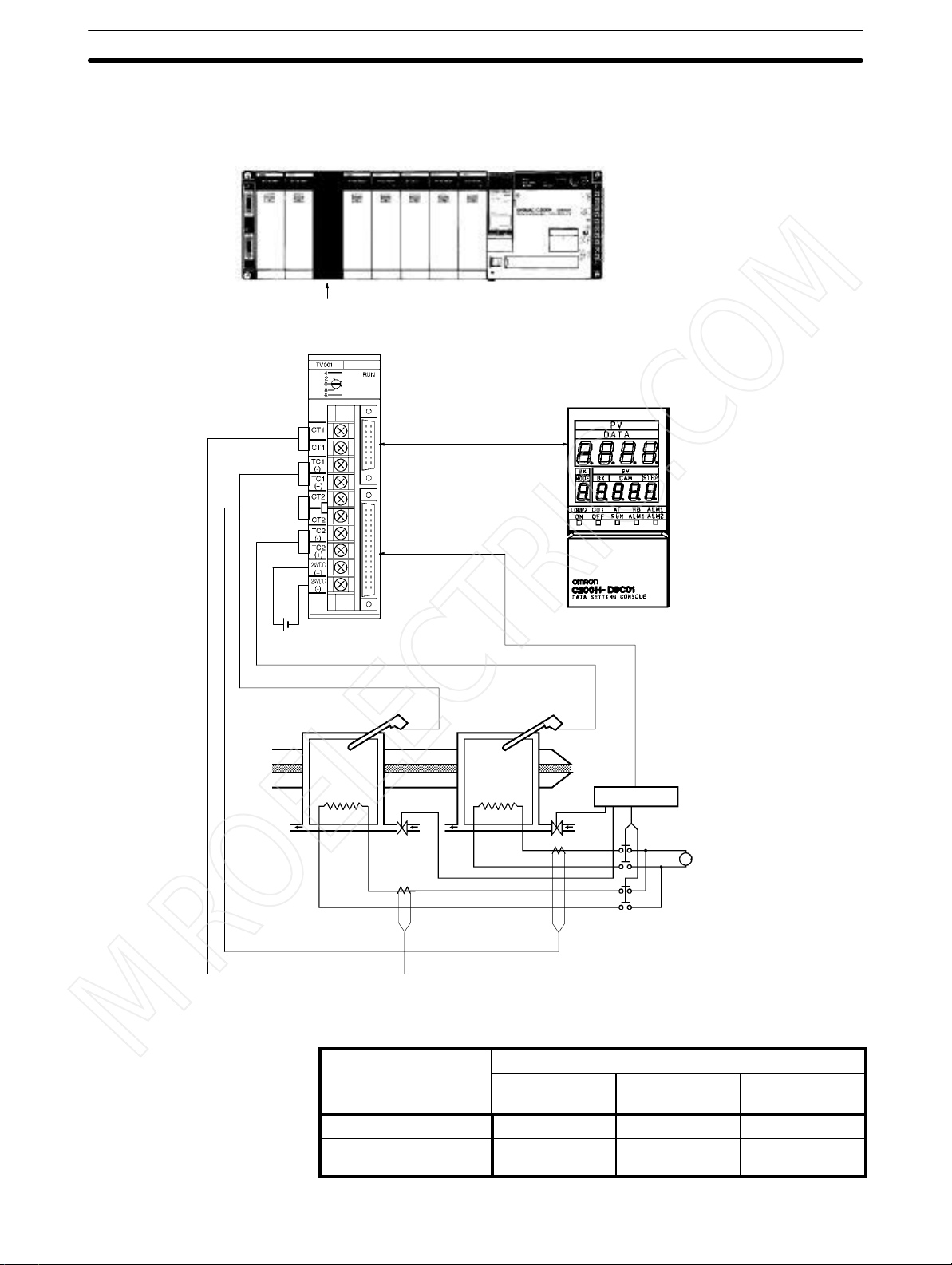
1-2 Basic System Configuration
C200H PC
Heat/Cool Temperature Control Unit:
C200H-TV00 (for thermocouples)
C200H-TV10 (for platinum resistance thermometers)
Connecting cables:
C200H-CN225 (2 m)
C200H-CN425 (4 m)
Recommended cable:
ES1000-CA021-051 (0.5 m)
ES1000-CA021-102 (1 m)
ES1000-CA021-202 (2 m)
Section 1-2
Data Setting Console
C200H-DSC01
24 VDC
Temperature
sensor
Loop 1 Loop 2
Extruder
Heater Heater
Valve
Coolant
Current
Transformer
(CT)
Heat/Cool Temperature Control Unit Models
Sensor
Thermocouple C200H-TV001 C200H-TV002 C200H-TV003
Platinum resistance
thermometer
Temperature
sensor
Remote I/O Terminal or
Connector Terminal
Block Converter Unit
(Refer to page 16)
Valve
Current Transformer
(CT)
Transistor
output
C200H-TV101 C200H-TV102 C200H-TV103
Relay box
Coolant
Solenoid switch
Output type
Voltage output Current output
3
Page 9
Basic System Configuration
MROELECTRIC.COM
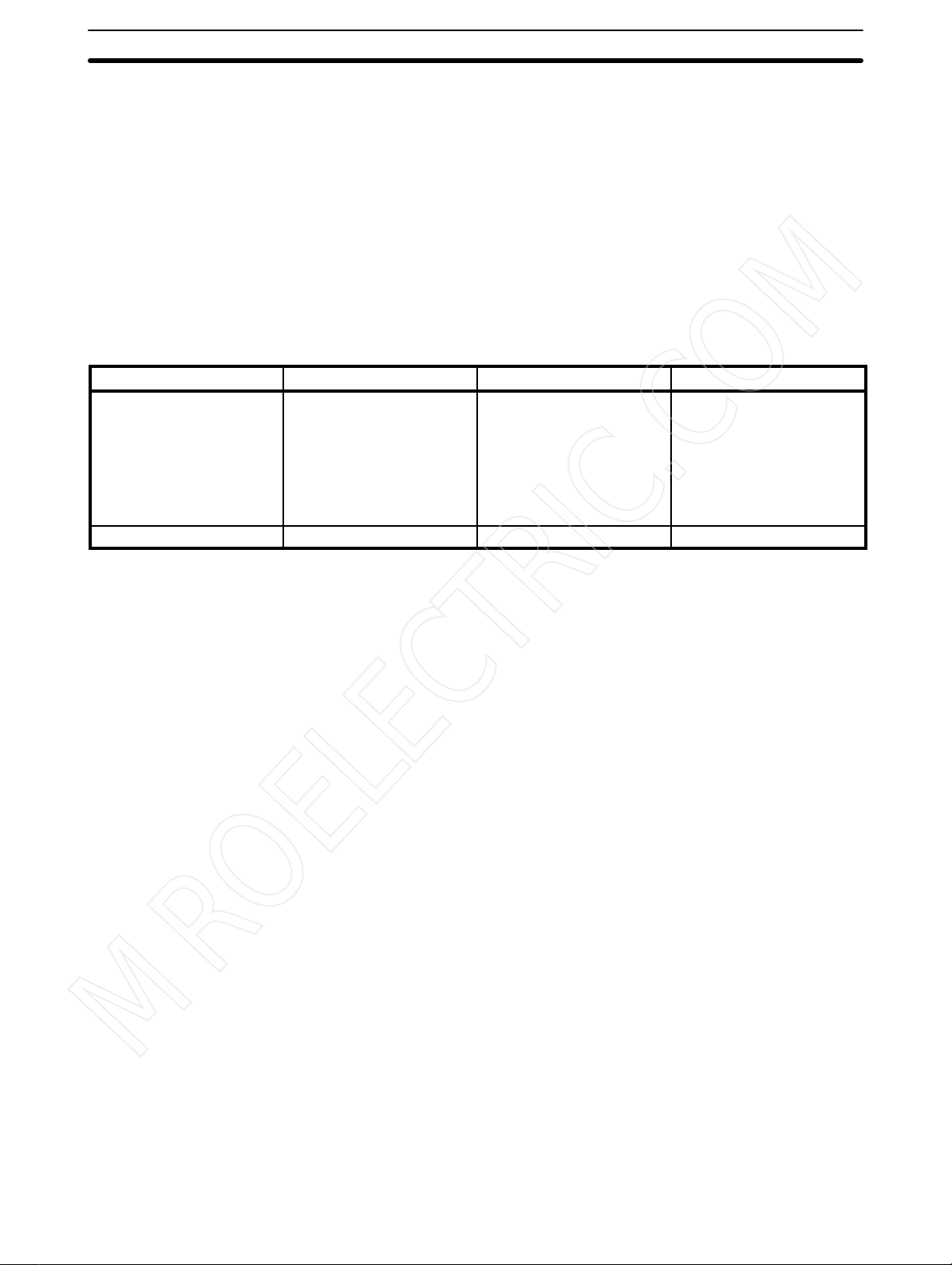
Number of Units The Heat/Cool Temperature Control Unit belongs to the C200H Special I/O Unit
group. A maximum of ten Special I/O Units (including PC Link Units) can be
mounted on each of the following Racks: CPU Rack, Expansion I/O Rack, and
Slave Rack.
Note Configure the Units such that the maximum current supplied for each Rack is
greater than or equal to the total current consumption for the Units.
Refer to the
C200H PC Operation Manuals
.
Section 1-2
Number of Units Mountable
on Slave Rack
A B C D
High-speed Counter Units
Position Control Units
(NC111/112)
ASCII Units
ID Sensor Units
Fuzzy Logic Units
4 units max. 8 units max. 6 units max. 2 units max.
The number of Special I/O Units used with a Slave Rack is limited by data transmission considerations, as shown in the table below. The numbers in the table
indicate the maximum number of Units of groups A, B, C, or D which can be used
with a single Slave Rack.
High-density and Mixed I/O
Units
Temperature Control Units
Heat/Cool Temperature
Control Units
PID Control Units
Cam Positioner Units
Note 1. When a combination of Units from groups A, B, C, and D is used, the number
from each group must satisfy both the following equations:
3A + B + 2C + 6D ≤ 12
A + B + C + D ≤ 8
2. Other Units can be added until the total number of Units reaches ten. If PC
Link Units are used, the number of Units including the PC Link Units must
not exceed ten.
Temperature Sensor Units
Voice Units
Position Control Units
(NC211)
Precautions The IR area of the C200H Special I/O Unit is allocated according to the setting of
not
the unit number switch on the front panel,
unit is mounted. Refer to
area.
Leave the two slots next to the CPU free. It is not possible to use devices connected to the CPU (such as the Programming Console) if these slots are occupied.
If the C200H Slave Rack is connected to another SYSMAC model Remote I/O
Master Unit, such as the C120, C500, C1000H, or C2000H, it is not possible to
use a Special I/O Unit with the C200H Slave Rack.
WARNING Always turn the C200H power off before connecting or disconnecting a Unit,
terminal block, or output connector.
Caution Connect thermocouples with the appropriate compensating conductor.
Wire I/O leads in separate ducts from power leads to prevent noise problems.
4
4-1 Memory Allocation
the address of the slot where the
for the allocation of the memory
Page 10

SECTION 2
MROELECTRIC.COM
Connections and Settings
This section provides information on the connections and settings of the Heat/Cool Temperature Control Unit.
2-1 Nomenclature 6. . . . . . . . . . . . . . . . . . . . . . . . . . . . . . . . . . . . . . . . . . . . . . . . . . . . . . . . . . . .
2-2 Switch Settings 7. . . . . . . . . . . . . . . . . . . . . . . . . . . . . . . . . . . . . . . . . . . . . . . . . . . . . . . . . . .
2-3 Wiring 10. . . . . . . . . . . . . . . . . . . . . . . . . . . . . . . . . . . . . . . . . . . . . . . . . . . . . . . . . . . . . . . . . .
2-3-1 Input Wiring 10. . . . . . . . . . . . . . . . . . . . . . . . . . . . . . . . . . . . . . . . . . . . . . . . . . . . . .
2-3-2 Output Wiring 13. . . . . . . . . . . . . . . . . . . . . . . . . . . . . . . . . . . . . . . . . . . . . . . . . . . .
2-3-3 Data Setting Console Cables 17. . . . . . . . . . . . . . . . . . . . . . . . . . . . . . . . . . . . . . . . .
5
Page 11
Nomenclature Section 2-1
MROELECTRIC.COM
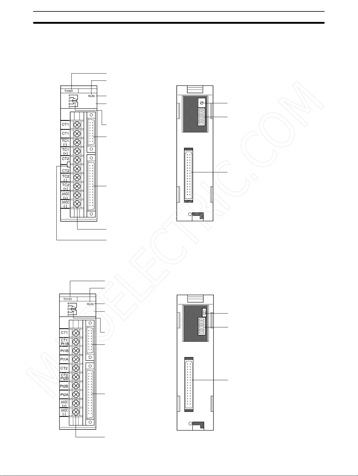
2-1 Nomenclature
C200H-TV00 (For Thermocouple)
Front Panel
Model label
Cover
RUN indicator
SW2
(switching memory contents
and setting direction under
the cover)
SW1
(Unit number setting)
Data Setting Console
connector
Output connector
Sensor input terminal block
Rear Panel
SW202
(input type setting)
SW203
(operation and function settings)
Rack connector
Cold junction compensator
C200H-TV10 (For Platinum Resistance Thermometer)
Front Panel Rear Panel
Model label
Cover
RUN indicator
SW2
(switching memory contents
and setting direction under
the cover)
SW1
(Unit number setting)
Data Setting Console
connector
Output connector
SW202
(input type setting)
SW203
(operation and function settings)
Rack connector
Sensor input terminal block
6
Page 12
Switch Settings
MROELECTRIC.COM
Indicators
RUN Lit when the Heat/Cool Temperature Control Unit is operating normally.
2-2 Switch Settings
The function and setting of switches are identical for all models, except SW202.
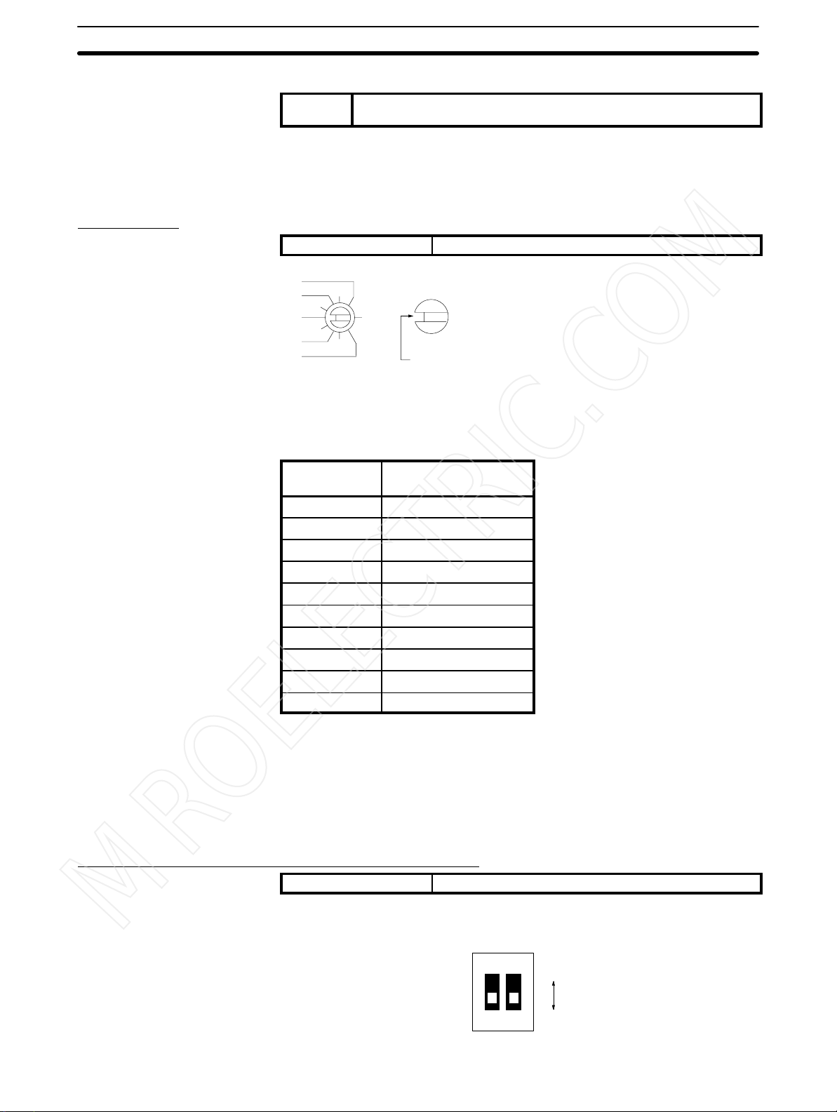
Unit Number
SW1 Unit number setting
Section 2-2
Unlit when an alarm occurs, and Unit operation stops.
4
2
0
8
6
The addresses are allocated as shown in the following table according to the
Unit number setting.
0 Wd 100 to 109
1 Wd 110 to 119
2 Wd 120 to 129
3 Wd 130 to 139
4 Wd 140 to 149
5 Wd 150 to 159
6 Wd 160 to 169
7 Wd 170 to 179
8 Wd 180 to 189
9 Wd 190 to 199
(3)
(1)
(9)
(7)
Unit no.
setting
(5)
The cut-out indicates the selected position. Negative numbers
are not indicated. Turn the switch with a flat-blade screwdriver.
Turn the switch until it clicks in position. Do not leave the switch
between two settings.
Allocated address
The switch is factory-set to 0.
Note If the Unit number is set to an existing Unit number, an alarm occurs and the
C200H does not operate.
Turn the C200H power off before setting the Unit number. If the setting is
changed with the power on, the new setting is not valid until the power is turned
off and back on again.
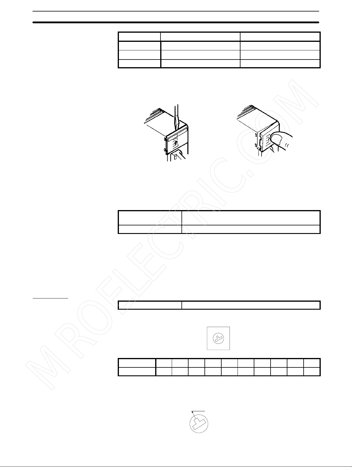
Switching Memory Contents and Setting Direction
SW2 Switching memory contents and setting direction
Remove the cover and set the switch with the tip of a ballpoint pen or a similar
object.
1
2
ON
OFF
OFF
7
Page 13
Switch Settings
MROELECTRIC.COM
Switch no. Pin 1 Pin 2
Function Switching memory contents Setting direction
ON Normal C200H PC
OFF Fixed Data Setting Console
The new setting is valid immediately after the switch setting is changed.
Removing and Attaching the Cover
Section 2-2
Removing the Cover Attaching the Cover
Insert a small flat-blade screwdriver between the case and
the cover at the top of the Unit
and lever off the cover.
Switching Memory Contents The methods for designating parameters differ as shown below.
Normal Parameters can be designated as required using
Fixed Parameters are allocated in advance.
Refer to
Setting Direction Selector Selects whether the data settings are made from the Data Setting Console or
from the C200H PC, using a user program or Programming Console.
Executed Bank Number
The setting of the executed bank number is made from the C200H PC, regardless of the ON/OFF setting of this switch.
4-1 Memory Allocation
commands. (Refer to
for details of the memory contents.
Place the right edge of the
cover against the case and
press into position.
4-1 Memory Allocation
).
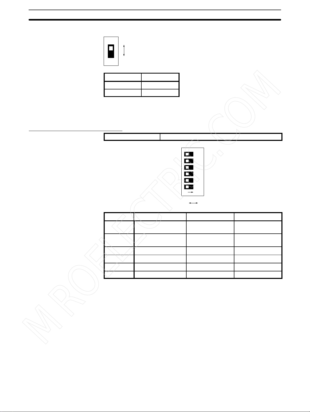
Input Type
SW202 Input type setting
C200H-TV00
3
2
4
1
0
5
9
6
7
8
Setting 0 1 2 3 4 5 6 7 8 9
Sensor type R S K J T E B N L U
The switch is factory-set to 2.
The selected position is shown by the arrow. Turn the switch with a small flat-
blade screwdriver.
Selected position
8
Page 14
Switch Settings
MROELECTRIC.COM
C200H-TV10
Setting Input type
OFF JPt 100
ON Pt 100
The switch is factory-set to OFF.
Appendix B Sensor Temperature Measurement Range
See
temperature range.
Operation and Function Setting
SW203 Operation and Function Setting
Section 2-2
OFF
ON
for the measurable
134562
NO
OFF ON
Pin no. Function OFF ON
6 Loop 1
Cooling control output
5 SP write mode Write to EEPROM
4 Loop 2 Enabled Disabled or not used
3 Display unit °C °F
2 Not used. --- --1 Control method PID control ON/OFF control
The switch is factory-set to OFF.
Loop 1 Cooling Control
Output
SP Write Mode
Loop 2 Set to “enabled” to use input loop 2, or to “disabled” to use only input loop 1. It is
This setting is valid when the heating output type is “current,” and input loop 2 is
not used (i.e., when pin no. 4 of switch 203 is ON).
This setting selects the SP storage memory. Set it to ON if the writing is to be
frequently changed.
not possible to use only input loop 2.
Pulses Current output
Write to RAM only
and RAM
Note Always set this switch to the ON (disabled) position when input loop 2 is not
used. A sensor error occurs if this switch is set to the OFF (enabled) position
when no temperature sensor is connected to loop 2.
Display Unit Selects whether displays and set values are shown on the Data Setting Console
in Celsius or in Fahrenheit.
Control Method Selects the method of control.
9
Page 15
Wiring
MROELECTRIC.COM
2-3 Wiring
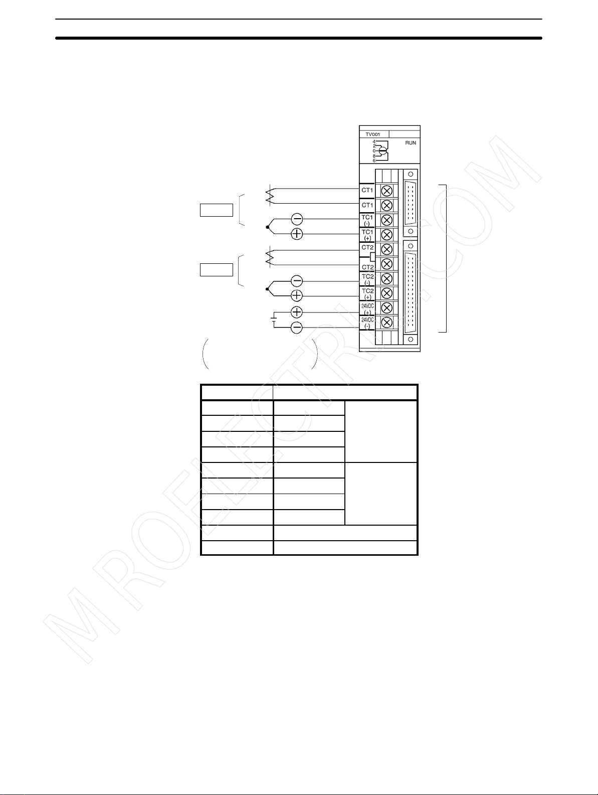
2-3-1 Input Wiring
C200H-TV00 Thermocouple
CT: Current Transformer
TC:Thermocouple
Section 2-3
CT
Loop 1
TC
CT
Loop 2
TC
24 VDC
0.2 A
The 24-VDC output from the
C200H CPU or the Power
Supply Units is convenient.
Terminal no. Terminal name
A0 CT Loop 1
A1 CT
A2 TC (–)
A3 TC (+)
A4 CT Loop 2
A5 CT
A6 TC (–)
A7 TC (+)
A8 24 VDC
A9 GND
A0
A1
A2
A3
A4
A5
A6
A7
A8
A9
Refer to the
table below.
10
Page 16
Wiring
MROELECTRIC.COM
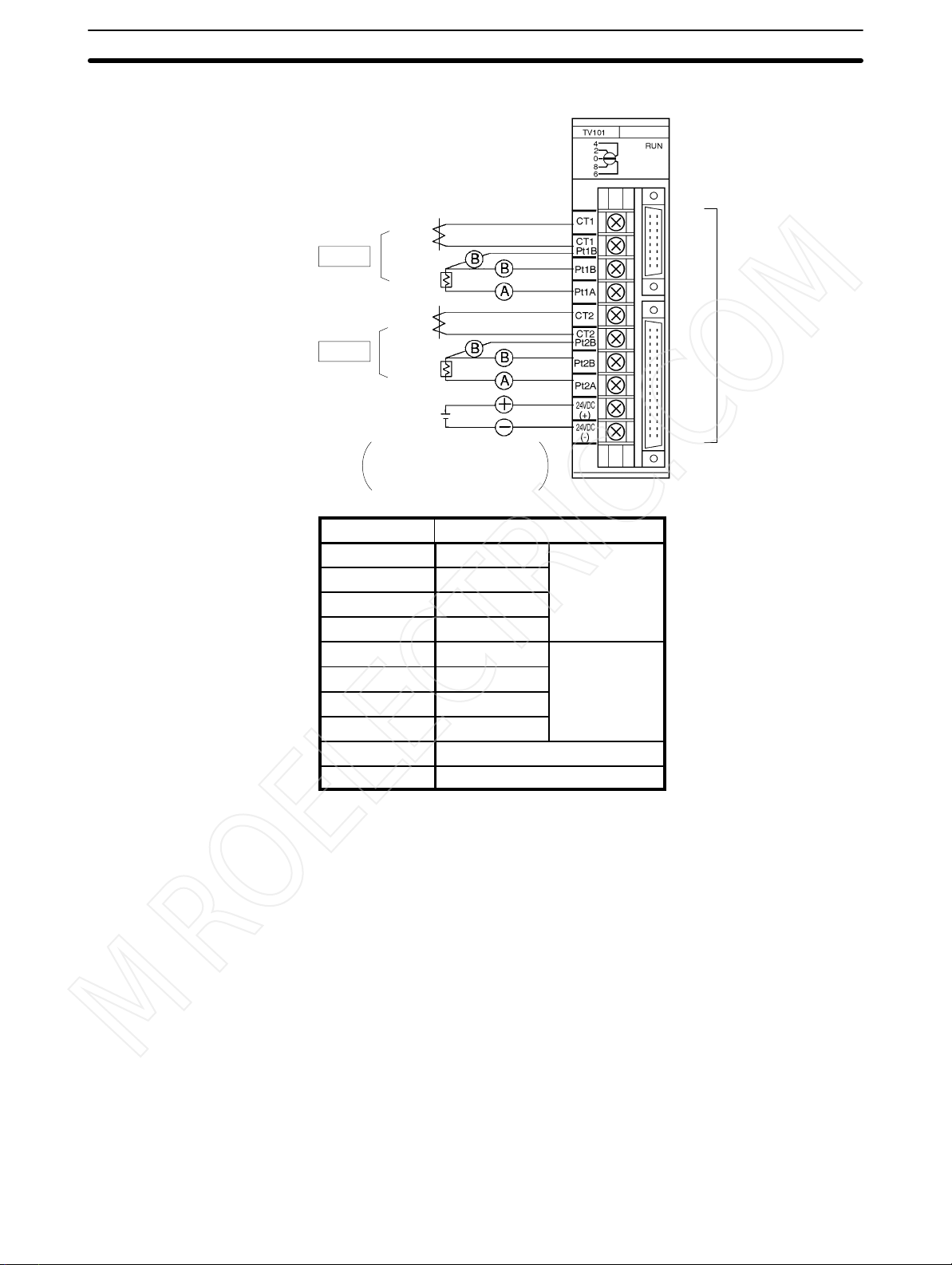
C200H-TV10 Platinum Resistance Thermometer
CT: Current Transformer
Pt: Platinum resistance thermometer
Section 2-3
Heater wire
CT
Loop 1
Pt
CT
Loop 2
Pt
24 VDC
0.2 A
The 24-VDC output from the
C200H CPU or the Power
Supply Units is convenient.
Terminal no. Terminal name
A0 CT Loop 1
A1 CT/Pt (B)
A2 Pt (B)
A3 Pt (A)
A4 CT Loop 2
A5 CT/Pt (B)
A6 Pt (B)
A7 Pt (A)
A8 24 VDC
A9 GND
A0
A1
A2
A3
A4
A5
A6
A7
A8
A9
Refer to the
table below.
Screw down Pt(B) and CT together at terminals A1 and A5.
Input Wiring Precautions
1, 2, 3...
1. Set the type of temperature sensor to thermocouple or platinum resistance
thermometer with SW202 on the rear of the Unit.
The Unit will not operate correctly if the switch setting does not match the
type of temperature sensor connected.
Do not connect different types of temperature sensors to Loop 1 and Loop 2.
2. If no input lead is connected to Loop 2, turn SW203-4 on the rear of the Unit
ON to disable Loop 2. A sensor error occurs if this switch is set to the OFF
(enabled) position when no temperature sensor is connected to Loop 2.
3. Be sure to connect (+) and (–), and (A) and (B) correctly.
4. Wire I/O leads in separate ducts from power leads to prevent noise problems.
5. A voltage of 24 VDC is used for the voltage output, current output and Data
Setting Console power supply.
6. The terminal block is removable. Make sure that it is attached correctly after
the input wiring connections are completed.
11
Page 17
y
y
y
j
y
major
j
Wiring
MROELECTRIC.COM
Section 2-3
Terminal Block
Connections
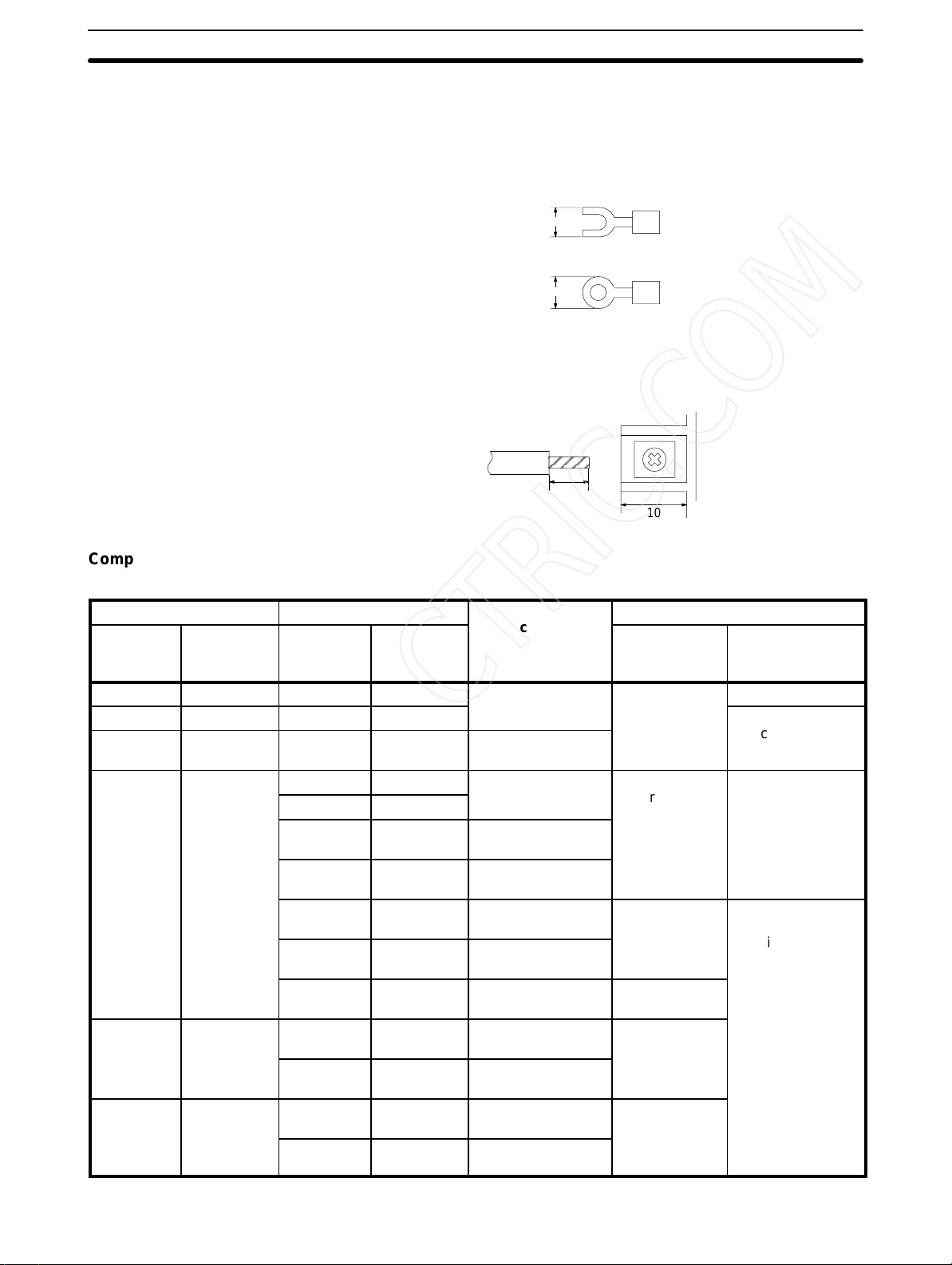
Crimp terminals are recommended for the wiring. Take care not to overtighten
the terminal screws. Tightening torque must not exceed 78 N cm (8 kg cm).
Crimp Terminals
The screws on the terminal block are M3.5 self-rising terminal screws. Use the
following types of M3.5 crimp terminals.
7 mm max.
7 mm max.
Soldered Lead
Strip insulation from 7 to 10 mm at the end of the wire and carefully solder the
lead.
7 to 10 mm
10
Compensating Conductors Connect a thermocouple with the appropriate compensating conductor from the
table below.
Type of thermocouple Compensating conductor
Symbol Previous
symbol
(reference)
B --- BX-G --R --- RX-G, SX-G --S --- RX-H, SX-H --- Heat-resistant,
K CA KX-G WCA-G
E CRC EX-G WCRC-G General-purpose,
J IC JX-G WIC-G General-purpose,
Symbol Previous
symbol
(reference)
KX-GS WCA-GS
KX-H WCA-H Heat-resistant,
KX-HS WCA-HS Heat-resistant,
WX-G WCA-G General-purpose,
WX-H WCA-H Heat-resistant,
VX-G WCA-G General-purpose,
EX-H WCRC-H Heat-resistant,
JX-H WIC-H Heat-resistant,
Classification by
application and
tolerance
General-purpose,
standard class
standard class
General-purpose,
standard class
standard class
precision class
standard class
standard class
standard class
standard class
standard class
standard class
standard class
Constituent materials
+ conductor – conductor
Copper Copper
Alloy with copper
or nickel as major
constituent
Alloy with nickel
or chrome as
or
ma
constituent
Iron
Copper
Alloy with nickel
or chrome as
major
constituent
Iron
Alloy with nickel as
major constituent
Alloy with copper
or nickel as major
constituent
12
Page 18
j
Wiring
MROELECTRIC.COM
Section 2-3
Type of thermocouple Constituent materialsClassification by
Symbol – conductor+ conductor
symbol
(reference)
T CC TX-G WCC-G General-purpose,
Wiring Platinum Resistance
Thermometers
Current Transformer Use an E54-CT1 or E54-CT3 Current Transformer (CT). Refer to
Compensating conductor
SymbolPrevious
TX-GS --- General-purpose,
TX-H WCC-H Heat-resistant,
TX-HS --- Heat-resistant,
Connect a platinum resistance thermometer with copper wire. All three leads
should have the same thickness and the same length to give them identical resistances. Do not branch the two (B) leads near the terminal block as this increases measurement errors.
Heater Burnout Detection
and installation dimensions.
Previous
symbol
(reference)
Classification by
application and
application and
tolerance
tolerance
Copper
standard class
precision class
standard class
precision class
for details of the Current Transformer specifications
Alloy with copper
or nickel as major
constituent
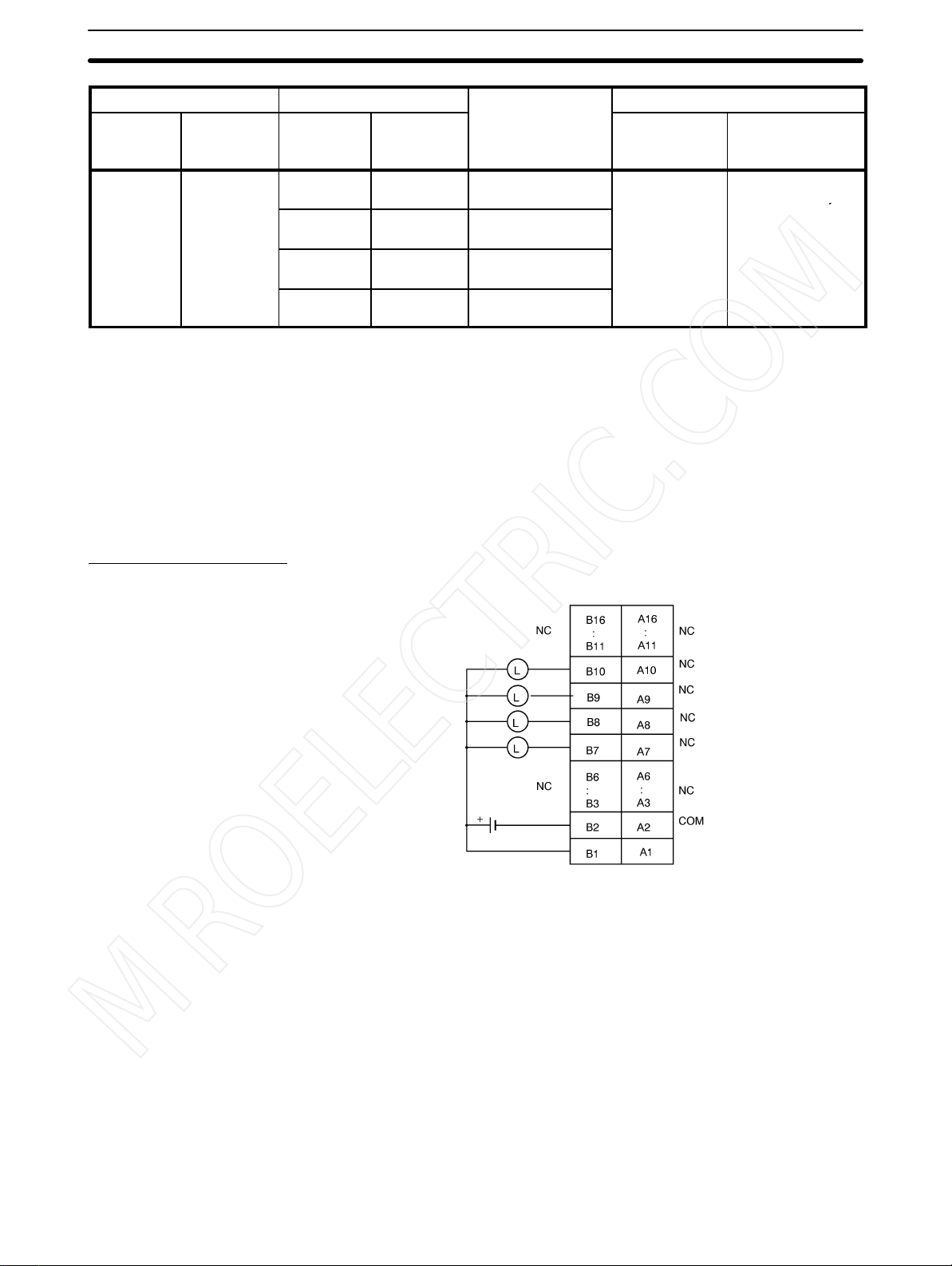
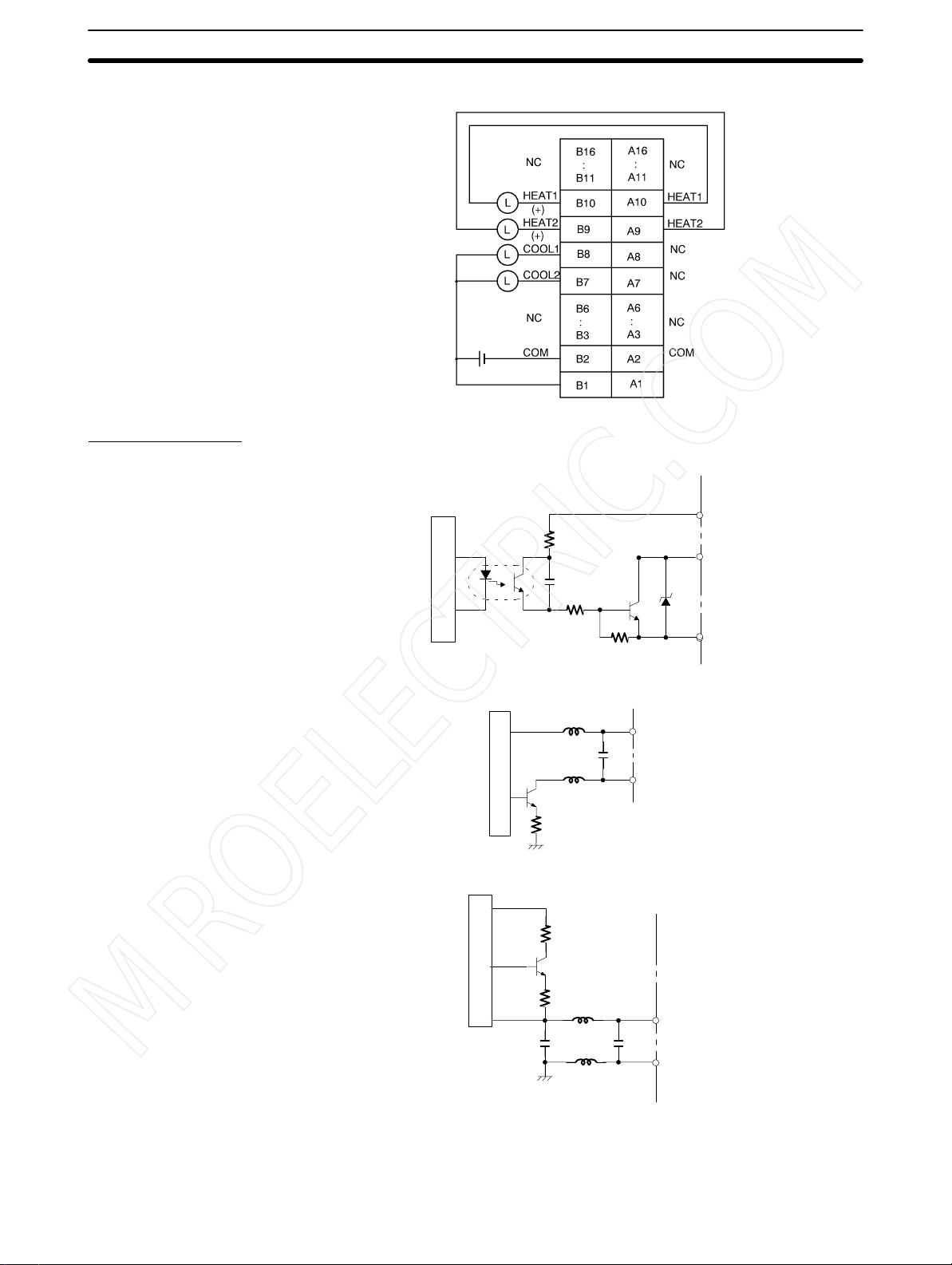
2-3-2 Output Wiring
Connection Diagrams
C200H-TV01 Transistor Output
Appendix C
HEAT1
HEAT2
COOL1
COOL2
COM
24 VDC
NC: Not connected
The pairs of terminals B2 to A2 and B1 to A1 are shorted internally. Always supply power to the 24-VDC terminal (B1) as this drives the internal circuits.
24 VDC
13
Page 19
Wiring
MROELECTRIC.COM
C200H-TV02/TV03 Voltage/Current Output
Section 2-3
(–)
(–)
+
Circuit Diagrams
C200H-TV01 Transistor Output
C200H-TV02 Voltage Output
24 VDC
Internal circuits
Internal circuits
24 VDC
24 VDC
OUT
COM
OUT (+)
OUT (–)
C200H-TV03 Current Output
Internal circuits
OUT (+)
OUT (–)
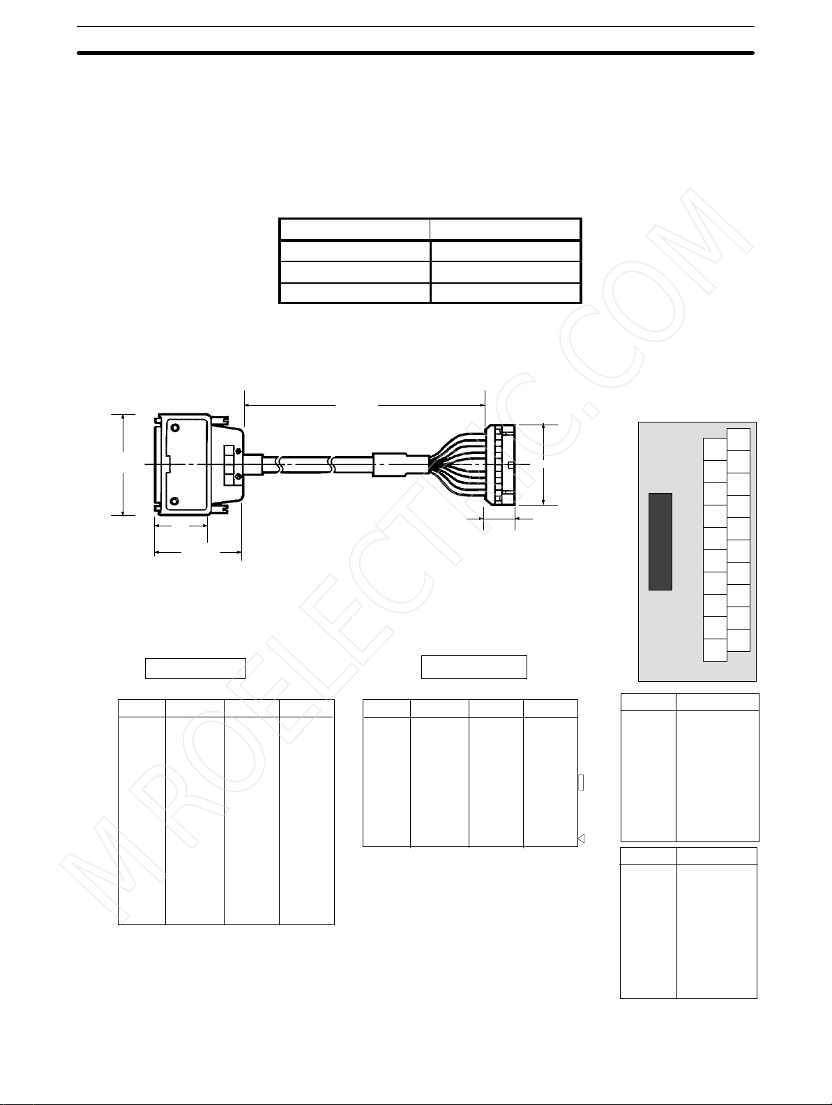
Applicable Connectors The following connector set manufactured by Fujitsu is included with the Unit:
FCN-361J032-AU (soldering connector)
FCN-360C032-B (cover)
14
Page 20
Wiring
MROELECTRIC.COM
Section 2-3
Connector Wiring
Precautions
Connection Precautions
After soldering the lead to each pin, insulate with heat-shrink tube to prevent
shorting with the adjacent terminal.
Tighten the screws after inserting the connector into the Unit. Push the connector firmly into the Remote I/O Terminal or Connector Terminal Block Converter
Unit until it fully locks.
Output Cable The output cables in the table below are recommended.
Model Cable length (L)
ES1000-CA021-051 0.5 m
ES1000-CA021-102 1 m
ES1000-CA021-202 2 m
32-pin connector
(manufactured by Fujitsu)
FCN-361J032-AU
63
28
46
L
20-pin connector
(manufactured by OMRON)
XG4M-2030
30
16.1
Wiring Diagrams
32-pin connector
20-pin connector
XW2B-20G
19
17
15
13
11
9
7
5
3
1
20
18
16
12
14
10
8
6
4
2
Pin no. Wire no. Pin no. Wire no.
B16
B15
B14
B13
B12
B11
B10
B9
B8
B7
B6
B5
B4
B3
B2
B1
#1
#2
#3
#4
#5
#6
#7
#8
#9
#10
A16
A15
A14
A13
A12
A11
A10
A9
A8
A7
A6
A5
A4
A3
A2
A1
#11
#12
#13
#14
#15
#16
#17
#18
#19
#20
Pin no. Wire no. Pin no. Wire no.
1
2
3
4
5
6
7
8
9
10
#1
#2
#3
#4
#5
#6
#7
#8
#9
#10
11
12
13
14
15
16
17
18
19
20
#11
#12
#13
#14
#15
#16
#17
#18
#19
#20
Note The pin numbers of the 20-pin con-
nector are marked for convenience.
Refer to them from the ∆ mark.
Note Pins A11 through A16 and B11
through B16 are not connected.
Pin no. Terminal no.
1
2
3
4
5
6
7
8
9
10
Pin no. Terminal no.
11
12
13
14
15
16
17
18
19
20
20
18
16
14
12
10
8
6
4
2
19
17
15
13
11
9
7
5
3
1
15
Page 21
Wiring
MROELECTRIC.COM
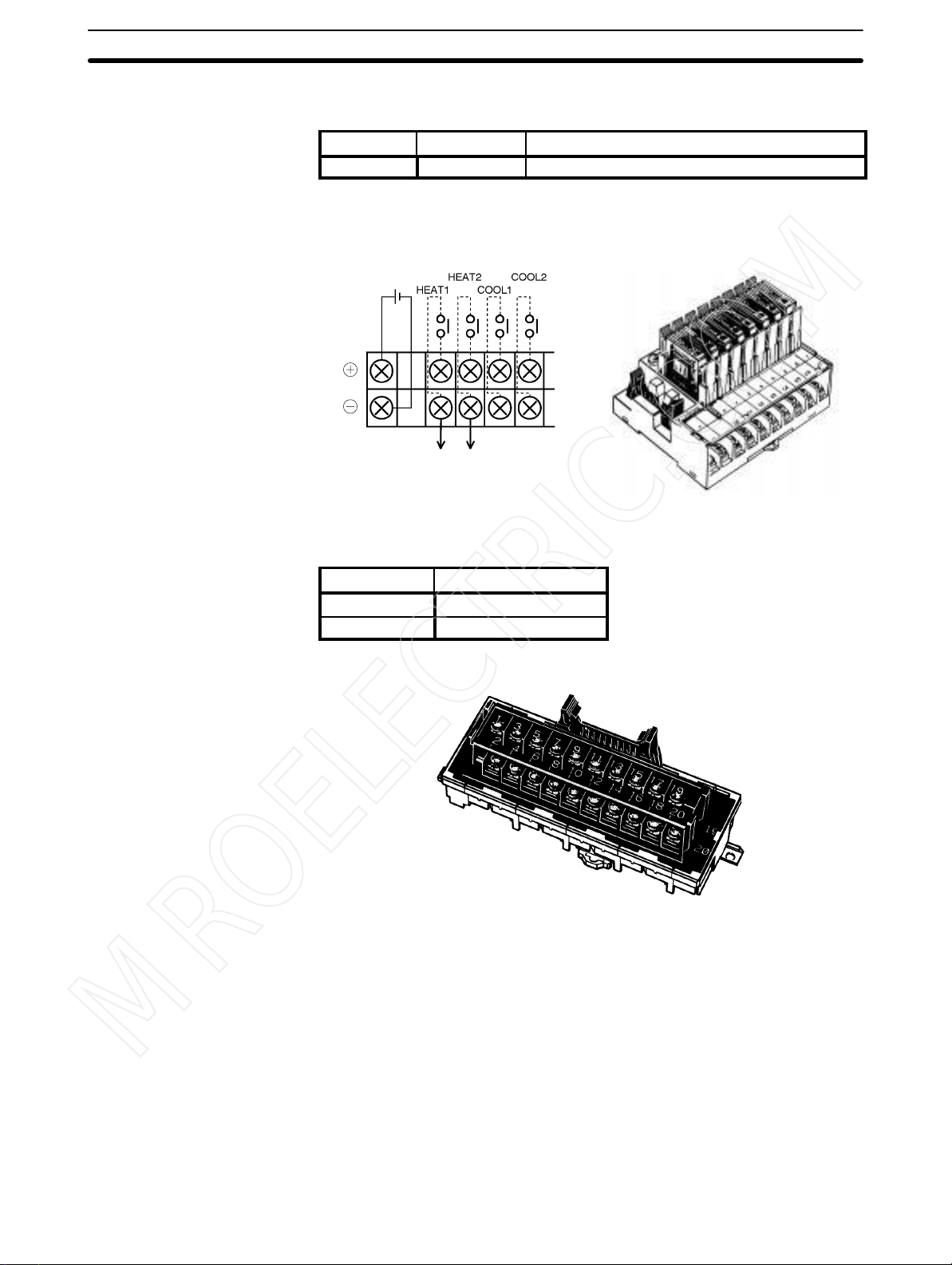
Remote I/O Terminal The Remote I/O Terminal in the table below is recommended for transistor out-
put.
Model Specification Relays used
G7TC-OC08 Common (+) 8 x G7T-1112S (max. resistive load: 220 VAC, 2A)
Note One P7TF-OS08 I/O Terminal and two G7T-1112S Relays may be
purchased separately and used.
Wiring Diagram External View
24 VDC
Wiring to the heater
Section 2-3
Connector Terminal Block
Converter Unit
External View
The Connector Terminal Block Converter Units in the table below are recommended for voltage output and current output type.
Model Terminal screw size
XW2B-20G4 M 2.4
XW2B-20G5 M 3.5
16
Page 22
Wiring
MROELECTRIC.COM
Section 2-3
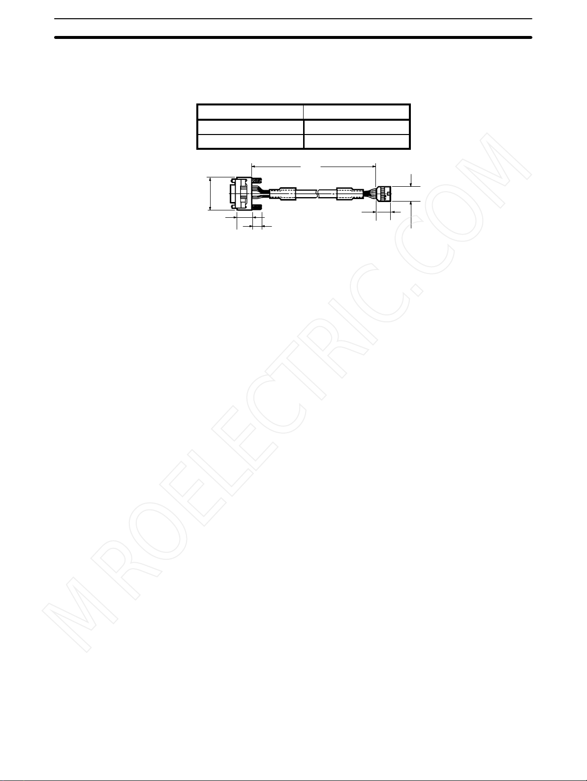
2-3-3 Data Setting Console Cables
Connecting Cable Use the connecting cables in the table below (sold separately) to connect the
Unit to the Data Setting Console.
Model Cable length (L)
C200H-CN225 2 m
C200H-CN425 4 m
L
Connection Precautions
1, 2, 3...
39
17.5
10
1. Tighten the lock screws after inserting the connector into the Unit.
2. Push the connector firmly into the Data Setting Console until the clips fully
lock.
3. Power is supplied through the connecting cable from the Heat/Cool Temperature Control Unit. Nothing appears on the Data Setting Console display if
no power is supplied to input terminals A8 and A9 of the Heat/Cool Temperature Control Unit.
4. Install the supplied connector cover when the Data Setting Console is not in
use.
17.3
16.1
17
Page 23

SECTION 3
MROELECTRIC.COM
Data Setting Console Operation
This section provides the basic operating procedures of the Data Setting Console including parameter settings and displays.
3-1 Operating Procedure 20. . . . . . . . . . . . . . . . . . . . . . . . . . . . . . . . . . . . . . . . . . . . . . . . . . . . . . .
3-2 Data Flow 21. . . . . . . . . . . . . . . . . . . . . . . . . . . . . . . . . . . . . . . . . . . . . . . . . . . . . . . . . . . . . . .
3-3 Nomenclature and Features 22. . . . . . . . . . . . . . . . . . . . . . . . . . . . . . . . . . . . . . . . . . . . . . . . .
3-3-1 Nomenclature 22. . . . . . . . . . . . . . . . . . . . . . . . . . . . . . . . . . . . . . . . . . . . . . . . . . . . .
3-3-2 Features 23. . . . . . . . . . . . . . . . . . . . . . . . . . . . . . . . . . . . . . . . . . . . . . . . . . . . . . . . .
3-4 Parameter Displays and Settings 24. . . . . . . . . . . . . . . . . . . . . . . . . . . . . . . . . . . . . . . . . . . . .
3-4-1 Table of Parameters 24. . . . . . . . . . . . . . . . . . . . . . . . . . . . . . . . . . . . . . . . . . . . . . . .
3-4-2 How to Display and Set Parameter Data 26. . . . . . . . . . . . . . . . . . . . . . . . . . . . . . . .
19
Page 24

Operating Procedure Section 3-1
MROELECTRIC.COM
3-1 Operating Procedure
After preparing the C200H PC, follow the procedure below to use the Heat/Cool
Temperature Control Unit.
1, 2, 3...
1. Set the switches on the front and rear panels according to the operating conditions. (Refer to
Set SW2-2 under the display cover to the OFF position to enable data setting from the Data Setting Console.
2. Mount to Rack.
Turn off the C200H power supply before mounting or dismounting the
C200H on the Rack.
3. Connect the input wiring. (Refer to
The 24-VDC power supply must be connected. The Data Setting Console
will not operate unless the 24-VDC power supply is connected. The sensors
can be connected immediately before the system is tested.
4. Connect the Data Setting Console. (Refer to
Cables
5. Turn on the 24-VDC and the C200H power supplies.
Set the C200H to PROGRAM mode.
6. Use the Data Setting Console to make the settings for the parameters that
need to be changed. (Refer to the rest of this section.)
7. Test operation and adjust data. (Refer to the rest of this section.)
Connect the output wiring and turn on the heater power . To start the test op-
eration, turn ON the RUN bit of the loop that is to be controlled with a device
such as the Programming Console. Monitor the control conditions and adjust the data until the required control is achieved. During operation, the
“bank no.” is switched to “executed bank no.” and cannot be changed from
the Data Setting Console. To change it, use a device such as the Programming Console, or use the user program.
8. Create the user programs. (Refer to
Programming.
Arrange the data for the test operation, and create the user programs for
data setting, monitoring, switching the bank number, and so on. Set SW2-2
under the display cover to the ON position to enable data setting from the
C200H PC.
9. Start operation.
.)
2-2 Switch Settings.
)
)
2-3 Wiring.
Section 4 PC Memory Allocation and
)
2-3-3 Data Setting Console
20
Page 25

Data Flow
MROELECTRIC.COM
3-2 Data Flow
Section 3-2
The data flow in the Heat/Cool Temperature Control Unit is shown in the diagram
below.
Read
Heating and
Cooling Temperature Control Unit
Write executed
bank no.
C200H PC
Write
Read
The read operation and setting the executed bank number are possible from a
user program or from a device, such as the Programming Console, regardless of
the ON/OFF setting of SW2-2.
Data written from the Data Setting Console and data written with write command
when SW2-1 (switching memory contents) is set to Normal are written to the
Heat/Cool Temperature Control Unit EEPROM and are consequently retained
when the power supply is turned off.
The SP value set when SW2-1 (switching memory contents) is set to Fixed and
executed bank number settings made from the C200H PC are written directly to
RAM and are not saved to EEPROM. This data is lost when the power supply is
turned off. The same data can be written to the RAM when the power is next
turned on and executes a user program. Settings made from the Programming
Console must be repeated each time the power is turned on.
ON
SW2-2
OFF
Data Setting Console
Data Settings from Data
Setting Console
Set SW2-2 under the display cover to the OFF position to enable data setting
from the Data Setting Console.
The “bank no.” can be set when operation is stopped (i.e., when the RUN bit is
OFF). During operation it is switched to “executed bank no.” and cannot be
changed from the Data Setting Console. To change the executed bank number,
use a user program or a device such as the Programming Console.
Operation begins when the RUN bit of the output relay turns ON. (For information on output relays, refer to
ming
.)
Section 4 PC Memory Allocation and Program-
21
Page 26

Nomenclature and Features
MROELECTRIC.COM
3-3 Nomenclature and Features
3-3-1 Nomenclature
Section 3-3
Display Key
Front View
(With cover open)
Data display
Operation indicators
Cover
Down Key
Up Key
Operation keys
Select parameters
Set data
Switch Loops
Side View
Panel mounting bracket
(Refer to
panel mounting.)
Appendix D Dimensions
Rear View
for details about
Level Key Loop Key
Heat/Cool Temperature Control Unit connector
Connecting cable (sold separately)
C200H-CN225 (2 m)
C200H-CN425 (4 m)
The bottom row of the operation keys have upper and lower labels. The upper
labels apply to Heat/Cool Temperature Control Unit operation. The lower labels
are for the Cam Positioner Unit.
Two display sheets are supplied: one for the Heat/Cool Temperature Control
Unit and one for the Cam Positioner Unit. If the Data Setting Console is to be
used with the Temperature Control Unit only, stick on the display sheet for the
Heat/Cool Temperature Control Unit.
Note The Data Setting Console will not operate unless a 24-VDC power supply is con-
nected to the Heat/Cool Temperature Control Unit input terminals.
22
Page 27

yy
Nomenclature and Features
MROELECTRIC.COM
3-3-2 Features
Data Display
Note Operation begins when the RUN bit of the output relay turns ON.
Operation Indicators
Section 3-3
Name Function
PV (Process
Value)
SV (Set Value) The display is as follows, according to the PV display contents.
BK (Bank
Number)
Name Function
LOOP2 Indicates whether the displayed settings relate to Loop 1 or Loop
OUT (Output) Turns ON when the heating output is ON
AT
(Auto-tuning)
HB (Heater
Burnout)
ALM1 (Alarm) Turns ON to indicate the temperature is in
Displays the PV or the parameter symbol selected with the Level
or Display Key (Refer to next page).
PV (process value): SV (set value) is displayed.
Parameter symbol: Setting/monitor data is displayed.
Displays the bank number of the data presently being displayed.
During operation, the executed bank number is displayed. (See
note)
2. Press the Loop Key and hold down for approximately 2
seconds to switch between Loop 1 and Loop 2.
Indicator OFF: Loop 1
Indicator ON: Loop 2
These indicators
for transistor output or voltage output
types.
Blinks at approximately 1 second intervals
during auto-tuning.
Turns ON to indicate a heater burnout
alarm.
the alarm range set with Alarm SV 1
(upper- and lower-limit alarm). Refer to the
following page.
relate to the
currently displayed
loop.
Display Patterns
Display Pattern 1 Display Pattern 2
Process
value
Executed bank number or displayed
bank number
Indicator OFF: Loop 1
Indicator ON: Loop 2
Set point
Executed
bank number
or displayed
bank number
Indicator OFF: Loop 1
Indicator ON: Loop 2
Parameter symbol
SV (Set value)
Monitored value
Execution status
23
Page 28

999 to 9999 C
Parameter Displays and Settings
MROELECTRIC.COM
Operation Keys
Level Key The parameter items are divided into three display groups (Refer
Display Key Press this key to select the required parameter from the selected
Section 3-4
Name Function
to display levels 0 to 2 on the next page). Press this key to switch
from one group to another. The display levels automatically cycle
in the sequence 0 –> 1 –> 2 –> 0 when the key is held down for
approximately 2 seconds.
display level 0 to 2 (Refer to table below).
The parameters cycle automatically when the key is held down.
3-4 Parameter Displays and Settings
3-4-1 Table of Parameters
0 Set point
1 SP lower limit
1 SP upper limit
Display
level
Parameter Display
Bank number
Alarm SV 1 (see
note 4)
Alarm SV 2 (see
note 4)
Input shift value
Proportional band
(see note 1)
Integral (reset)
time (see note 1)
Derivative (rate)
time (see note 1)
Loop Key Press this key for approximately two seconds to switch between
Up Key Press this key to increment SV.
Down Key Press this key to decrement an SV.
Write Read Loop
symbol
Yes Yes Yes Yes SP lower limit to
---
See
bk
note 5
al-1
al-2
in-5
sl-l
sl-h
Yes Yes Yes Yes
Yes Yes Yes Yes
Yes Yes Yes Yes –99.9° to
Yes Yes Yes Yes 0.0° to 999.9°C 40.0°C
p
Yes Yes Yes Yes 0 to 9999 s 240 s
i
Yes Yes Yes Yes 0 to 9999 s 40 s
d
Yes Yes Yes No Sensor measur-
Yes Yes Yes No (Sensor measur-
Loop 1 and Loop 2.
The SV increment continuously while the key is held down. The
SV display blinks when the value reaches its upper limit.
The SV decreases continuously while the key is held down. The
SV display blinks when the value reaches its lower limit.
Bank
no.
Yes Yes No 1 to 8 1 26
no.
Data range Default value Page
0°C 26
SP upper limit
Alarm mode
TC 1, 4, 5:
0° to 9999°C
Other TCs:
–999° to 9999°C
Pt 1, 4, 5:
0.0° to 999.9°C
Other Pts:
–99.9° to
999.9°C
999.9°C
ing range lower
limit to (SP upper
limit – 1 digit)
ing range lower
limit + 1 digit) to
SP upper limit
0°C
0°C
0.0°C 27
TC: –200°C
Pt: –99.9°C
TC: 1,300°C
Pt: 450.0°C
27
27
28
28
24
Page 29

Parameter Displays and Settings
MROELECTRIC.COM
Section 3-4
Display
level
2 Heating output
Parameter
Dead band (see
note 1)
Cooling coefficient (see note 1)
Heating control
period (see notes
1 and 3)
Cooling control
period (see notes
1 and 3)
Hysteresis (see
note 2)
Alarm hysteresis
(see note 4)
Heater current
monitor (see
note 3)
Heater burnout
current (see
note 3)
variable monitor
Cooling output
variable monitor
Auto-tuning start/
stop (see note 1)
Copy bank
Input-type monitor
Alarm 1 mode
Alarm 2 mode
symbol
c-db
c-sc
cp
c-cp
hys
hysa
ct
hb
h-o
c-o
at
bcpy
in-t
alt1
alt2
ReadWriteDisplay
Yes Yes Yes No TC: –999 to
Yes Yes Yes No 0.01 to 99.99 1.00 29
Yes Yes Yes No 1 to 99 s 20 s 29
Yes Yes Yes No 1 to 99 s 20 s 29
Yes Yes Yes Yes 0.0° to 999.9°C 0.8°C 29
Yes Yes Yes No 0.0° to 999.9°C 0.2°C 30
No Yes Yes No 0.0 to 55.0 A 0.0 A
Yes Yes Yes No 0.0 to 50.0
No Yes Yes No 0.0% to 100.0% 0.0 % 31
No Yes Yes No 0.0% to 100.0% 0.0 % 31
Yes Yes Yes No --- --- 31
Yes Yes Yes No --- --No Yes No No 0 to 9 Setting for
Yes Yes Yes No
Yes Yes Yes No 2
Loop
no.
no.
9999°C
Pt: –99.9 to
999.9°C
0.0: No heater
burnout detection, alarm signal
OFF
50.0: No heater
burnout detection, alarm signal
ON
0 to 9
0°C 28
0.0 A
SW202
2
PageDefault valueData rangeBank
30
31
32
Yes: Possible.
No: Not possible or not required.
Note 1. Only when advanced PID control is selected. (switch 203-1 = OFF)
2. Only when ON/OFF control is selected. (switch 203-1 = ON)
3. Valid only for C200H-TV03 (current output type).
4. Does not apply when Alarm Mode = 0.
5. Writing is not possible during operation (i.e., when RUN is ON).
6. Thermocouple = TC
Platinum Resistance Thermometer = Pt
25
Page 30

Parameter Displays and Settings
MROELECTRIC.COM
3-4-2 How to Display and Set Parameter Data
Basic Operation
When not specifically explained, use the keys as described in the following.
Changing the Display Level
When the Level Key is pressed, the leading parameter for each level is displayed.
Changing Parameters
When the Display Key is pressed, the parameters are displayed in order. There
may be skips depending on the model and DIP switch settings.
Changing the SV
Pressing the Up Key or the Down Key changes the SV. The SV is retrieved automatically.
Changing the Loop
The loop is switched each time the Loop Key is pressed. It can be confirmed by
means of the LOOP 2 indicator.
PV and SV (Display Level 0)
Section 3-4
Bank Number (Display Level 0)
PV
PV
SV
Valid SV Range
Set the set point in the range between the SV lower limit and the SV upper limit.
Error Display
When a sensor error occurs, one of the codes below and the detected temperature blink alternately in the PV display.
ser1
ser2
serr
Bank number parameter symbol
Temperature is out of the range: (sensor measurement range +
10%FS). That is, 10%FS below the lower limit or 10%FS above
the upper limit. Includes broken or incorrect sensor wiring.
ser1: Loop1 or Loop1 and Loop2 simultaneously.
ser2: Loop2
Abnormality in the cold junction compensating circuit. Applies to
thermocouple type only .
Process temperature (monitored every 500 ms)
Set point of currently selected bank and loop (unit: °C or °F)
pp
SV
Settings
• The bank number can be changed.
• The changed SV is reflected in the bank number display (BK).
Bank Number and Executed Bank Number
The executed bank number cannot be changed from the Data Setting Console.
26
Currently set bank number.
During control operation: Executed bank number
Control operation interrupted: Currently displayed bank number
Page 31

Parameter Displays and Settings
MROELECTRIC.COM
When changing these parameters from the Data Setting Console, stop operation. While operation is stopped, the bank number setting can be changed.
Alarm SV 1 (Display Level 0)
Section 3-4
PV
SV
Alarm SV 2 (Display Level 0)
Input Shift Value (Display Level 0)
If the displayed temperature value differs from the actual temperature value due
to the sensor position or some other conditions, set the input shift value such that
the correct temperature is displayed.
Not valid when Alarm mode = 0.
PV
SV
Not valid when Alarm mode = 0.
PV
SV
Alarm 1 parameter symbol
Alarm SV of currently selected bank and loop (unit: °C or °F)
Alarm 2 parameter symbol
Alarm SV of currently selected bank and loop (unit: °C or °F)
Input shift value parameter symbol
Input shift value of currently selected bank and loop (unit:
°C or °F)
Proportional Band (Display Level 0)
PV
SV
• This sets the proportional band. It is valid only when SW203-1 is set to OFF
(i.e., PID control).
• This value is reflected even when auto-tuning (AT) is executed.
• If this value is set to “0.0,” ON/OFF control is executed.
Integral (Reset) Time (Display Level 0)
PV
SV
• This sets the integral time. It is valid only when SW203-1 is set to OFF (i.e., PID
control).
• This value is reflected even when auto-tuning (AT) is executed.
Derivative (Rate) Time (Display Level 0)
PV
Proportional band parameter symbol
Proportional band of currently selected bank and loop
(unit: °C or °F)
Integral time parameter symbol
Integral time of currently selected bank and loop (unit: second)
Derivative time parameter symbol
SV
Derivative time of currently selected bank and loop
(unit: second)
27
Page 32

Parameter Displays and Settings
MROELECTRIC.COM
• This sets the integral time. It is valid only when SW203-1 is set to OFF (i.e., PID
control).
• This value is reflected even when auto-tuning (AT) is executed.
SP Lower Limit (Display Level 1)
Section 3-4
• Settings can be made within the following range:
• When powering up or starting, the lower limit of the measuring range for sen-
SP Upper Limit (Display Level 1)
• Settings can be made within the following range:
• When powering up or starting, the upper limit of the measuring range for sen-
PV
SV
Sensor measuring range lower limit to (SP upper limit – 1 digit)
sors set by the rear-panel SW202 (sensor type) is set automatically. For example, if SW202 is set to “2,” the thermocouple type is set to “–200.” However, the
SP lower limit will not be changed if the current SV lies inside the sensor measuring range.
PV
SV
(SP limit + 1 digit) to sensor measuring range upper limit
sors set by the rear-panel SW202 (sensor type) is set automatically. For example, if SW202 is set to “2,” the thermocouple type is set to “1300.” However, the
SP upper limit will not be changed if the current SV lies inside the sensor measuring range.
SP lower limit parameter symbol
SP lower limit of currently selected loop
(unit: °C or °F)
SP upper limit parameter symbol
SP upper limit of currently selected loop
(unit: °C or °F)
Dead Band (Display Level 1)
PV
SV
• This sets the cooling output dead band, and it is valid when SW203-1 (PID control) is OFF.
• The relation between the dead band and the set temperature is as shown in the
illustration below.
Output volume
Heating output
100%
0%
Dead band parameter symbol
Dead band of currently selected loop (unit: °C or °F)
Dead band
Cooling output
Temperature
Set value
28
Page 33

Parameter Displays and Settings
MROELECTRIC.COM
Cooling Coefficient (Display Level 1)
Section 3-4
Control Period (Display Level 1)
PV
SV
• This sets the coefficient for finding the cooling P constant. It is valid when
SW203-1 is OFF (PID control). The formula for calculating the cooling P
constant is as follows:
Cooling P constant = heating P constant x cooling coefficient
• The I/D constant is the same for cooling as for heating.
PV
SV
PV
SV
• This sets the control period. It is valid when SW203-1 is OFF (PID control), and
only when the heater model is not the C200H-TV03 (current output type).
• Cooling loop 1 is invalid when SW203-6 is ON (current output).
• The control period is the time required to complete one transistor output or volt-
age output ON/OFF cycle.
Cooling coefficient parameter symbol
Cooling coefficient of currently selected loop
Heating control period parameter symbol
Heating control period of currently selected loop
(Unit: seconds)
Cooling control period parameter symbol
Cooling control period of currently selected loop
(Unit: seconds)
Hysteresis (Display Level 1)
ON
OFF
ON time
Control period
PV
SV
• Hysteresis prevents control output chattering and eliminates noise influences.
• When switching from ON to OFF, operation proceeds at the set point. When
switching from OFF to ON, operation proceeds at a lower point determined by
the hysteresis SV, as shown in the following illustration.
ON
Hysteresis parameter symbol
Hysteresis of currently selected bank and loop
(Unit: °C or °F)
Hysteresis
OFF
Set point
29
Page 34

Parameter Displays and Settings
MROELECTRIC.COM
Hysteresis is applied in the following situations.
• When ON/OFF control is selected (i.e., when SW203-1 is ON).
• When advanced PID control is selected (i.e., when SW203-1 is OFF) and P
(proportional band) is 0.
Alarm Hysteresis (Display Level 1)
Section 3-4
PV
SV
• Alarm hysteresis prevents alarm output chattering and eliminates noise influences. It is invalid when both alarm mode 1 and alarm mode 2 are “0.”
• When switching from OFF to ON, operation proceeds at the set point. When
switching from ON to OFF, a hysteresis SV operating band is provided which
may be either higher or lower than the set point, depending on the alarm mode.
Hysteresis
OFF
The alarm output is OFF if the present temperature lies within the hysteresis
band when the Unit is turned on.
Heater Current Monitor (Display Level 1)
Alarm hysteresis parameter symbol
Alarm hysteresis of currently selected loop
(Unit: °C or °F)
Upper Limit Mode Lower Limit Mode
ON
Set point Set point
ON
Hysteresis
OFF
PV
SV
Note Cannot be set.
• Valid for C200H-TV03 (current output type).
Heater Burnout Detection Current (Display Level 1)
PV
SV
• Invalid for C200H-TV03 (current output type).
• Make the setting using one of the two values shown in the table below. Refer to
Appendix C Heater Burnout Detection
0.0 No heater burnout detection. Alarm signal OFF.
50.0 No heater burnout detection. Alarm signal ON.
Heater current monitor parameter symbol
Heater current of currently selected loop
(Unit: Ampere). Monitored every 500 ms.
Heater burnout detection current parameter
symbol
Heater burnout detection current of currently
selected loop (Unit: Ampere)
The setting can be changed from this display.
for more details about the alarm SVs.
30
Page 35

Parameter Displays and Settings
MROELECTRIC.COM
Control Output Variable Monitor (Display Level 2)
Section 3-4
PV
SV
PV
SV
The relationship between the control output variable and control period is defined by the formula below:
Control output variable (%) = x 100
The control output variable during ON/OFF control (when SW203-1 on the rear
panel is ON) is ON = 100% and OFF = 0%.
Auto-tuning Start/Stop (Display Level 2)
PV
SV
AT start/stop parameter symbol
Heating control output variable monitor parameter
symbol
Heating output variable of currently selected loop
(Unit: %). Monitored every 500 ms.
Cooling control output variable monitor parameter
symbol
Cooling output variable of currently selected loop
(Unit: %). Monitored every 500 ms.
ON time
Control period
Process temperature
Set point
AT indicator blinks
• The auto-tuning operation begins when the Up Key is pressed. The PV and SV
return to the respective present temperature and set point displays. While
auto-tuning is in progress the AT indicator blinks.
• To interrupt, press the Level and Display Keys again to display at. When at
appears, press the Up Key. When the interrupt is executed, the A T display disappears and the process temperature is displayed.
• When auto-tuning is completed, the AT indicator stops blinking and the P, I, an d
D data is written to EEPROM.
Copy Bank (Display Level 2)
PV
SV
Copy bank parameter symbol
Input-type Monitor (Display Level 2)
Execute bank copy
• When the Up Key is pressed, the data other than the set point is copied from
bank number 1 to banks 2 through 8.
• Use this method to create data in banks 2 through 8 by slightly modifying the
data in bank number 1.
PV
Bank being copied
Input-type monitor parameter symbol
Bank copy completed
SV
Note Cannot be set.
Input type currently set with SW202 on the rear panel.
Thermocouple: Setting no.
Platinum resistance thermometer: 0: JPt (OFF), 1: Pt (ON)
31
Page 36

Parameter Displays and Settings
MROELECTRIC.COM
Alarm 1 and Alarm 2 Modes (Display Level 2)
Section 3-4
PV
SV
PV
SV
Select the desired alarm type from the following chart and set the number (X: set
value)
Alarm
Mode
0No alarm
1 Upper- and lower-limit alarm
2 Upper-limit alarm
Alarm Type Alarm Range
Alarm 1 Mode parameter symbol
Alarm 1 Mode of currently selected loop
Alarm 2 Mode parameter symbol
Alarm 2 Mode of currently selected loop
0SP
x x
x
3 Lower-limit alarm
4 Upper- and lower-limit range alarm
5 Upper- and lower-limit alarm with
standby sequence
6 Upper-limit alarm with standby
sequence
7 Lower-limit alarm with standby
sequence
8 Absolute-value upper-limit alarm
9 Absolute-value lower-limit alarm
Standby Sequence
When the power is turned on, the temperature is below the set point, so alarm
output status occurs with regard to the lower limit alarm. In this situation, if “lower
limit alarm with standby sequence” is selected, the standby sequence recognizes that the value is out of the alarm range and then outputs an alarm when the
value enters the alarm range once more.
x
x x
x x
x
x
x
x
32
Page 37

Parameter Displays and Settings
MROELECTRIC.COM
Lower Limit Alarm with Standby Sequence
The standby sequence is restarted in the following situations.
• When the power is turned on.
• When the set point is changed.
• When the executed bank number is changed.
• When the alarm mode is changed.
• When changing from stop to run.
Hysteresis
OFF point
Alarm SV
0°C
Alarm output
Standby sequence
cancel point
Section 3-4
33
Page 38

SECTION 4
MROELECTRIC.COM
PC Memory Allocation and Programming
This section provides the C200H PC’s memory allocation for the Heat/Cool Temperature Control Unit. Basic programming
procedures and examples are also provided.
4-1 Memory Allocation 36. . . . . . . . . . . . . . . . . . . . . . . . . . . . . . . . . . . . . . . . . . . . . . . . . . . . . . .
4-1-1 Memory Allocation T able 37. . . . . . . . . . . . . . . . . . . . . . . . . . . . . . . . . . . . . . . . . . .
4-1-2 Memory Contents 38. . . . . . . . . . . . . . . . . . . . . . . . . . . . . . . . . . . . . . . . . . . . . . . . .
4-1-3 Table of Commands 41. . . . . . . . . . . . . . . . . . . . . . . . . . . . . . . . . . . . . . . . . . . . . . . .
4-2 Data Flow 43. . . . . . . . . . . . . . . . . . . . . . . . . . . . . . . . . . . . . . . . . . . . . . . . . . . . . . . . . . . . . . .
4-3 Programming 43. . . . . . . . . . . . . . . . . . . . . . . . . . . . . . . . . . . . . . . . . . . . . . . . . . . . . . . . . . . .
4-3-1 Example with SW2-1 in the Fixed Position 43. . . . . . . . . . . . . . . . . . . . . . . . . . . . .
4-3-2 Example 1: Write with SW2-1 in the Normal Position 44. . . . . . . . . . . . . . . . . . . . .
4-3-3 Example 2: Read with SW2-1 in the Normal Position 47. . . . . . . . . . . . . . . . . . . . .
4-3-4 Operation Timing 50. . . . . . . . . . . . . . . . . . . . . . . . . . . . . . . . . . . . . . . . . . . . . . . . . .
35
Page 39

Memory Allocation Section 4-1
MROELECTRIC.COM
4-1 Memory Allocation
Memory Allocation According to the Unit number switch setting on the front of the C200H Heat/Cool
Temperature Control Unit, 10 words are allocated for each Unit number in the
Special I/O Unit IR area between IR100 to IR199, which is used as the I/O
refresh data area. The IR area used by the C200H Temperature Control Unit is
refreshed on each C200H PC I/O refresh cycle.
C200H PC
IR area
Unit#0 IR100 to IR109
Unit#1 IR110 to IR119
Unit#2 IR120 to IR129
Unit#3 IR130 to IR139
Unit#4 IR140 to IR149
Unit#5
Unit#6 IR160 to IR169
Unit#7 IR170 to IR179
Unit#8 IR180 to IR189
Unit#9 IR190 to IR199
Selecting Allocated Data The data allocated to each IR word due to the Unit number setting is determined
IR150 to IR159
Note A Duplicate I/O Unit error occurs if the set Unit number corresponds to the num-
During the PC’s I/O refresh,
each cycle is executed for
the outputs (PC to Heat/Cool
Temperature Control Unit)
followed by the inputs (Heat/
Cool Temperature Control
Unit to PC).
ber of an existing Special I/O Unit.
by the setting of SW2-1 on the front of the Unit.
ON Normal All data can be set using commands.
OFF Fixed Parameters are fixed for the set point (SP).
OUT
IN
Heat/Cool Temperature Control Unit
I/O refresh data area
Wd (n)
to
Wd (n+2)
Wd (n+3)
to
Wd (n+9)
(n=100 + 10 x Unit number)
The terms “output” and
“input” are defined from
the C200H PC side.
Output
refresh
Input
refresh
This setting becomes valid immediately when the switch is set.
36
Page 40

Memory Allocation Section 4-1
MROELECTRIC.COM
4-1-1 Memory Allocation Table
SW2-1 in Fixed Position
(n=100 + 10 x Unit number)
I/O Word
Output n
n+1
n+2 Loop 1 executed bank
Input n+3
n+4
n+5
n+6
n+7
n+8 Loop 1 status data
n+9 Loop 2 status data
Bit
15 14 13 12 11 10 09 08 07 06 05 04 03 02 01 00
Loop 1 SP (see note)
0 to 9, F 0 to 9 0 to 9 0 to 9
Loop 2 SP (see note)
0 to 9, F 0 to 9 0 to 9 0 to 9
Loop 2 executed bank
number number
Loop 1 PV (see note)
0 to 9, F 0 to 9 0 to 9 0 to 9
Loop 2 PV (see note)
0 to 9, F 0 to 9 0 to 9 0 to 9
Loop 1 SP (see note)
0 to 9, F 0 to 9 0 to 9 0 to 9
Loop 2 SP (see note)
0 to 9, F 0 to 9 0 to 9 0 to 9
Loop 1 executed bank
number number
0 Sen-
0 Sen-
sor
error
sor
error
CT
overflow
CT
overflow
Loop 2 executed bank
0 0
0 0
Loop 1 Loop 2 0
RUN
0
0 0 0
RUN
0 0 Coo
RUN
0 0 Coo
0
ling
output
ling
output
RUN
0
Hea
AT HB AL1 AL2
ting
output
Hea
AT HB AL1 AL2
ting
output
SW2
2 1
Note For four-digit BCD and platinum resistance thermometer data, the least
significant digit = 0.1, and the most significant digit (F) = minus (–). For example,
“F200” represents –20.0°C for a platinum resistance thermometer.
SW2-1 in Normal Position
(n=100 + 10 x Unit number)
I/O Word
15 14 13 12 11 10 09 08 07 06 05 04 03 02 01 00
Output
Input n+3
n Read/write instruction
Read/write Loop no. Bank no. Instruction
n+1
n+2 Loop 1 executed bank
Write data (see note)
0 to 9, F 0 to 9 0 to 9 0 to 9
number
Loop 1 PV (see note)
0 to 9, F 0 to 9 0 to 9 0 to 9
Loop 2 executed bank
number
Bit
Loop
0
1
RUN
0 Loop 2
RUN
0 0 0 Write
request
37
Page 41

digit is 0.1. S
ifi
Memory Allocation Section 4-1
MROELECTRIC.COM
I/O BitWordI/O
Input n+4
Word
n+5
n+6 0 Write
n+7
n+8 Loop 1 status data
n+9 Loop 2 status data
Loop 2 PV (see note)
0 to 9, F 0 to 9 0 to 9 0 to 9
Read data (see note)
0 to 9, F 0 to 9 0 to 9 0 to 9
error
Loop 1 executed bank
number number
0 Sen-
0 Sen-
sor
error
sor
error
CT
overflow
CT
overflow
Loop 2 executed bank
0 0
0 0
0 0 Write
0 0 0 0 Read
complete
0 0 0
RUN
RUN
0 0 Co
0 0 Co
oling
output
oling
output
Heat-
AT HB AL1 AL2
ing
output
Heat-
AT HB AL1 AL2
ing
output
00010203040506070809101112131415
com-
plete
SW2
2 1
Note For four-digit BCD and platinum resistance thermometer data, the least
significant digit = 0.1, and the most significant digit (F) = minus (–). For example,
“1000” represents 100.0°C for a platinum resistance thermometer.
4-1-2 Memory Contents
SW2-1 in Fixed Position
I/O Address Data item Data contents
Word Bit
Output n 15 to 00 Loop 1 SP
n+1 15 to 00 Loop 2 SP
n+2 15 to 12 Loop 1
executed
bank
number
11 to 08 Loop 2
executed
bank
number
07 --- Not used. Set to 0.
06 Loop 1
RUN
05 --- Not used. Set to 0.
04 Loop 2
RUN
03 to 00 --- Not used. Set to 0.
Sets the Loop 1 and Loop 2 SP (set point) as 4-digit BCD data.
For platinum resistance thermometer data, the least significant
et the most sign
Note These specified values apply to the bank number set with Wd
(n+2) and can are written directly to RAM. (Refer
Sets the bank number executed for Loop 1 and Loop 2 as 1-digit
BCD data. Set executed bank numbers from 1 to 8. If the value is
set out of this range, the bank number reverts to the previous
value.
This the Loop 1 Run/Stop bit. When it is set to 1, operation starts;
when it is set to 0, operation stops.
This the Loop 2 Run/Stop bit. When it is set to 1, operation starts;
when it is set to 0, operation stops.
(n=100 + 10 x Unit number)
cant digit to F for minus (–).
page 43
)
38
Page 42

BCD dat
t
dat
t
Memory Allocation Section 4-1
MROELECTRIC.COM
I/O Data contentsData itemAddress
BitWord
Input n+3 15 to 00 Loop 1 PV
n+4 15 to 00 Loop 2 PV
n+5 15 to 00 Loop 1 SP
n+6 15 to 00 Loop 2 SP
n+7 15 to 12 Loop 1
executed
bank
number
11 to 08 Loop 2
executed
bank
number
07 to 02 --- Not used. Each bit is set to 0.
01 SW2-2 Outputs the ON/OFF status of SW2-2 (setting direction).
00 SW2-1 Outputs the ON/OFF status of SW2-1 (switching memory
n+8 Loop 1
n+9 Loop 2
15 --- Not used. Set to 0.
14 Sensor
error
13 CT
overflow
12 to 09 --- Not used. Each bit is set to 0.
08 RUN Bit set to 1 during operation.
07 and 06 --- Not used. Each bit is set to 0.
05 Cooling
control
output
04 Heating
control
output
03 AT Bit set to 1 during auto-tuning (AT).
02 HB Bit set to 1 if the detected heater current drops
01 AL1
00 AL2
Outputs the Loop 1 and Loop 2 PV (process value) as 4-digit
p
a. For platinum resistance thermometer data, the leas
significant digit is 0.1. The most significant digit is F for minus (–).
Outputs the Loop 1 and Loop 2 SP (set point) as 4-digit BCD
p
a. For platinum resistance thermometer data, the leas
significant digit is 0.1. The most significant digit is F for minus (–).
Outputs the bank number currently executed for Loop 1 and Loop
2 as 1-digit BCD data.
0: Data Setting Console
1: C200H PC
contents).
0: Fixed
1: Normal
Loop 1/2
status data
Bit set to 1 if the sensor is not connected, a sensor
wire is broken, or the input data exceeds the
operational temperature range.
Bit set to 1 when the detected heater current
exceeds 55.0 A.
Bit set to 1 when the control output (transistor or
voltage output) is ON.
below the set heater burnout current value. (HB:
heater burnout)
Bit set to 1 when the temperature enters the set
alarm range (Refer to page 23).
Note If the setting direction of the Temperature Control Unit is set to the C200H PC
and the C200H is in program mode, all word data will be 0. Therefore, if the
C200H in program mode has been set to continuous control, the Temperature
Control Unit executes temperature control when the C200H stops operating,
judging that the SP has been changed to 0°C. To prevent this, set SW2-2 of the
Temperature Control Unit to OFF (i.e., the setting direction is set to the Data Setting Console) before the C200H stops operating and reset SW2-2 after the
C200H restarts.
39
Page 43

BCD data. For latinum resistance thermometer data, the least
Memory Allocation Section 4-1
MROELECTRIC.COM
SW2-1 in Normal Position
(n=100 + 10 x Unit number)
I/O Address Data item Data contents
Word Bit
Output n 15 and 14 Read/Write The data bit sets operation to read or write.
Write = 01 Read = 00
13 and 12 Loop no. The data bit sets the Loop Number to which the
read or write operation applies.
Loop 1 = 01, Loop 2 = 10
11 to 08 Bank no. Sets the bank number to which the read or write
operation applies as 1-digit BCD data. Set executed
bank numbers from 1 to 8.
07 to 00 Command Sets the command code (Refer to page 41) for the
read or write operation as 2-digit BCD data.
n+1 15 to 00 Write data Set the SP for a write operation as 4-digit BCD data. The least
significant digit of the actual data matches the least significant
digit of the set value. Set the most significant digit to F for minus
(–) values. The write operation commences when the write
request flag (Wd (n+2), bit 00) turns ON.
n+2 15 to 12 Loop 1
executed
bank
number
11 to 08 Loop 2
executed
bank
number
07 --- Not used. Set to 0.
06 Loop 1
RUN
05 --- Not used. Set to 0.
04 Loop 2
RUN
03 to 01 --- Not used. Set to 0.
00 Write
request
Input n+3 15 to 00 Loop 1 PV
n+4 15 to 00 Loop 2 PV
n+5 15 to 00 Read data Outputs the data read with the commands set with Wd (n). The
n+6 15 to 12 --- Not used. Each bit is set to 0.
11 Write error Bit set to 1 when the write data exceeds the set permissible
10 and 09 --- Not used. Each bit is set to 0.
08 Write
complete
Set the bank number currently executed for Loop 1 and Loop 2 as
1-digit BCD data. Executed bank numbers are from 1 to 8. If the
value is set out of this range, the bank number reverts to the
previous value.
This the Loop 1 Run/Stop bit. When it is set to 1, operation starts;
when it is set to 0, operation stops.
This the Loop 2 Run/Stop bit. When it is set to 1, operation starts;
when it is set to 0, operation stops.
Turn this bit ON to write the data in Wd (n+1), by means of this
command.
Turn this bit OFF after the Write Complete Flag (Wd (n+6), bit 08)
turns ON.
Outputs the Loop 1 and Loop 2 PV (process value) as 4-digit
BCD data. For platinum resistance thermometer data, the least
significant digit is 0.1. Set the most significant digit to F for minus
(–) values.
least significant digit of the actual data matches the least
significant digit of the set value. Set the most significant digit to F
for minus (–) values.
range. The bit is automatically set to 0 when the Write Request
Flag (Wd (n+2), bit 00) turns OFF.
Bit set to 1 when the write operation executed by means of the
command set with Wd (n) ends normally. The bit is automatically
set to 0 when the Write Request Flag (Wd (n+2), bit 00) turns
OFF.
Read/Write
command
Read/Write
command
40
Page 44

Memory Allocation Section 4-1
MROELECTRIC.COM
I/O Data contentsData itemAddress
BitWord
Input n+6 07 to 01 --- Not used. Each bit is set to 0.
n+7
n+8 Loop 1
n+9 Loop 2
00 Read
complete
15 to 12 Loop 1
executed
bank
number
11 to 08 Loop 2
executed
bank
number
07 to 02 --- Not used. Each bit is set to 0.
01 SW2-2 Outputs the ON/OFF status of SW2-2 (setting direction).
00 SW2-1 Outputs the ON/OFF status of SW2-1 (switching memory
15 --- Not used. Set to 0.
14 Sensor
error
13 CT
overflow
12 to 09 --- Not used. Each bit is set to 0.
08 RUN Bit set to 1 during operation.
07 and 06 --- Not used. Each bit is set to 0.
05 Cooling
control
output
04 Heating
control
output
03 AT Bit set to 1 during auto-tuning (AT).
02 HB Bit set to 1 if the detected heater current drops
01 AL1
00 AL2
Bit set to 1 when the read operation executed by means of the
command set with Wd (n) ends normally. The bit is automatically
set to 0 when the next command is set.
Outputs the bank number currently executed for Loop 1 and Loop
2 as 1-digit BCD data.
0: Data Setting Console
1: C200H PC
contents).
0: Fixed
1: Normal
Loop 1/2
Bit set to 1 if the sensor is not connected, a sensor
wire is broken, or the input data exceeds the
operational temperature range.
Bit set to 1 when the detected heater current
exceeds 55.0 A.
Bit set to 1 when the control output (transistor or
voltage output) is ON.
below the set heater burnout current value. (HB:
heater burnout)
Bit set to 1 when the temperature enters the set
alarm range (Refer to page 23).
status data
4-1-3 Table of Commands
The command codes shown below are set in bits (n Wd) 07 to 00 when the
SW2-1 (switching memory contents) on the front panel is set in the Normal position.
Parameter Com-
mand
Set point 0 0 Yes Yes Yes Yes SV lower limit to SV upper
Executed bank number 0 2 Yes Yes Yes No 1 to 8 0001 to
Write Read Loop
no.
Bank
no.
Actual data
range
limit
Write/Read
data range
0008
Default value
0°C
1
41
Page 45

9999°C
()
Memory Allocation Section 4-1
MROELECTRIC.COM
Alarm SV 1 (see note 4) 0 3 Yes Yes Yes Yes
Alarm SV 2 (see note 4) 0 4 Yes Yes Yes Yes
Input shift value 0 5 Yes Yes Yes Yes –99.9 to
Proportional band (see
note 1)
Integral (reset) time
(see note 1)
Derivative (rate) time
(see note 1)
SP lower limit 1 0 Yes Yes Yes No Sensor measuring range
SP upper limit 1 1 Yes Yes Yes No (SP lower limit + 1 digit) to
Dead band (see note 1) 1 C Yes Yes Yes No
Cooling coefficient (see
note 1)
Heating control period
(see notes 1 and 3)
Cooling control period
(see notes 1 and 3)
Hysteresis (see note 2) 1 8 Yes Yes Yes Yes 0.0 to 999.9°C 0000 to
Alarm hysteresis (see
note 4)
Heater current monitor
(see note 3)
Heater burnout current
(see note 3)
Heating control output
variable monitor
Cooling control output
variable monitor
Auto-tuning start/stop
(see note 1)
Copy bank 2 2 Yes No Yes No --- 0001 --Input-type monitor 2 3 No Yes No No 0 to 9 0000 to
Parameter Default valueWrite/Read
mand
0 6 Yes Yes Yes Yes 0.0 to 999.9°C 0000 to
0 7 Yes Yes Yes Yes 0 to 9999 s 0000 to
0 8 Yes Yes Yes Yes 0 to 9999 s 0000 to
1 D Yes Yes Yes No 0.01 to 99.99 0001 to
1 7 Yes Yes Yes No 1 to 99 s 0001 to
1 6 Yes Yes Yes No 1 to 99 s 0001 to
1 9 Yes Yes Yes No 0.0 to 999.9°C 0000 to
1 A No Yes Yes No 0.0 to 55.0 A 0000 to
1 B Yes Yes Yes No 0.0 to 50.0 A 0000 to
2 0 No Yes Yes No 0.0 to 100.0% 0000 to
2 6 No Yes Yes No 0.0 to 100.0% 0000 to
2 1 Yes No Yes No ---
ReadWriteCom-
Loop
no.
Bank
no.
Actual data
range
Alarm mode
TC 1, 4, 5:
0 to 9999°C
Other TCs:
–999 to
°
Pt 1, 4, 5:
0.0 to 999.9°C
Other Pts:
–99.9 to
999.9°C
999.9°C
lower limit to (SP upper limit
value – 1 digit)
sensor measuring range upper limit
TC: –999 to 9999°C
Pt: –99.9 to 999.9°C
0.0: No heater burnout
detection, alarm signal OFF
50.0: No heater burnout
detection, alarm signal ON
data range
0000 to
9999
F999 to
9999
F999 to
9999
9999
9999
9999
F999 to
9999
9999
99
99
9999
9999
0550
0050
1000
1000
Start = 0001
Stop = 0000
0009
0°C
0°C
0.0°C
40.0°C
240 s
40 s
TC: –200°C
Pt: –99.9°C
TC: 1,300°C
Pt: 450.0°C
0°C
1.00
20 s
20 s
0.8°C
0.2°C
0.0 A
0.0 A
0.0%
0.0%
---
Setting for
SW202
42
Page 46

Programming
MROELECTRIC.COM
Section 4-3
Parameter Default valueWrite/Read
mand
Alarm 1 mode 2 4
Alarm 2 mode 2 5
Note 1. Only when advanced PID control is selected. (switch 203-1 = OFF)
Yes Yes Yes No 0 to 9 0000 to
Yes: Possible.
No: Not possible or not required.
2. Only when ON/OFF control is selected. (switch 203-1 = ON)
3. Invalid only for C200H-TV03 (current output type).
4. Does not apply when Alarm Mode = 0.
5. Thermocouple = TC
ReadWriteCom-
Platinum Resistance Thermometer = Pt
Loop
no.
Bank
no.
Actual data
range
data range
2
0009
4-2 Data Flow
Refer to
Unit.
Data Settings Before setting data with a user program or the Programming Console, turn ON
SW2-2 of the Unit to enable data setting from the C200H PC. However, the
executed bank number can be set with a user program or from the Programming
Console regardless of the ON/OFF setting of SW2-2.
SW2-1 (switching memory contents) may be set in either the OFF (Fixed) or ON
(Normal) position, but care is required as the setting of this switch changes the
stored data contents.
3-2 Data Flow
for the data flow in the Heat/Cool Temperature Control
4-3 Programming
4-3-1 Example with SW2-1 in the Fixed Position
Description and Conditions
Sample Program
1 cycle ON
(C200H)
Example: The user program makes the following settings:
Conditions:C200H-TV001 (thermocouple)
1070023515 10701
Fixed
Loop 1 SP = 80°C
Loop 2 SP = 200°C
Loop 1 executed bank number = 1
Loop 2 executed bank number = 3
SW203 set to 2 (K).
Unit number set to 0 (allocated memory: IR100 to IR109).
SW2-1 set OFF (Fixed) and SW2-2 set ON (C200H PC).
MOV (21)
MOV (21)
MOV (21)
END (01)
Set #0080 for word 100 (Loop 1 SP).
#0080
100
Set #0200 for word 101 (Loop 2 SP).
#0200
101
Set #1350 for word 102 (executed bank number).
#1350
102
#1350 run bit ON
Loop 1, loop 2 begin operation
Loop 2 executed bank number
Loop 1 executed bank number
43
Page 47

Programming
MROELECTRIC.COM
Be sure to set the correct values for the Loop 1 and Loop 2 SP.
The SV value is #0000 (0°C) if no data is set. If the executed bank number is set
to a value out of the range from 1 to 8 the bank number reverts to the previous
value (default value = 1).
Reading Monitored Data Read monitored data into the program using Wd (n+3) to (n+9).
4-3-2 Example 1: Write with SW2-1 in the Normal Position
Description and Conditions
Example The user program makes the following settings:
Loop 1 SP = 200°C (Bank no. = 1)
Loop 2 SP = 250°C (Bank no. = 2)
Loop 1 executed bank number = 1
Loop 2 executed bank number = 2
Loop 1 heater burnout current value = 2.0 A
Loop 2 heater burnout current value = 2.5 A
Conditions C200H-TV001 (thermocouple)
SW203 set to 2 (K).
Unit number set to 0 (allocated memory: IR100 to IR109).
SW2-1 set ON (Normal) and SW2-2 set ON (C200H PC).
Section 4-3
44
Page 48

Programming
MROELECTRIC.COM
Sample Program
10701
10700
(C200H)
Normal
DIFU (13)
SW2-2 (10701) switch ON detection
(C200H PC)
23200
Section 4-3
25315 10701
1 cycle ON Normal
23200
23201
23202
23201
10608
(C200H)
Write complete
10700
MOV (21)
MOV (21)
MOV (21)
DIFD (14)
S
R
23201
#1250
102
#5100
100
#0200
101
23203
KEEP(11)
23202
Program runs when operation is started or
SW2-2 turned ON
#1250
Loop 1, loop 2 begin operation
Loop 2 executed bank number
Loop 1 executed bank number
#5100
SP setting instruction
Bank number
Bit data : 0101
Loop 1
Write data (200°C)
Write
Waits for write completion, then
proceeds to next step.
23203
23204
23203
10608
23205
Next page
Write complete
MOV (21)
MOV (21)
DIFD (14)
MOV (21)
MOV (21)
S
R
#6200
100
#0250
101
23205
KEEP(11)
23204
#501B
100
#0020
101
#6200
SP setting instruction
Bank number
Bit data:
Write data (250°C)
Waits for write completion, then
proceeds to next step.
#501B
Heater burnout current
value command
Bank number not required
Bit data:
Write data (2A)
0110
Loop 2
Write
0101
Loop 1
Write
45
Page 49

Programming
MROELECTRIC.COM
Section 4-3
23206
23205
10608
Write complete
23207
23201
23203
23205
23207
10608
Write complete
DIFD (14)
MOV (21)
MOV (21)
S
R
S
R
23207
KEEP(11)
23206
#601B
100
#0025
101
KEEP(11)
10200
Waits for write completion, then
proceeds to next step.
#601B
Write data (2.5A)
Write request
Heater burnout current
value command
Bank number not required
Bit data:
0110
Loop 2
Write
END (01)
46
Page 50

Programming
MROELECTRIC.COM
Timing Chart
Section 4-3
1 cycle
25315
(1 cycle ON)
23201
23202
23203
23204
23205
23206
23207
10200
(Write request)
(Write complete)
In addition to the timing above, 23201 turns ON for one cycle on the ON rising
edge of SW2-2 (10701).
10608
j: Point of Write command execution
4-3-3 Example 2: Read with SW2-1 in the Normal Position
Description and Conditions
Example: The following data is read from the indicated addresses:
Conditions:C200H-TV001 (thermocouple)
Loop 1 PV: DM0000
Loop 1 heating control output variable: DM0001
Loop 2 heater current: DM0002
This read program is to be executed after writing the data with program
example 1.
SW203 set to 2 (K).
Unit number set to 0 (allocated memory: IR100 to IR109.
SW2-1 set ON (Normal) and SW2-2 set ON (C200H PC).
47
Page 51

Programming
MROELECTRIC.COM
Sample Program
Section 4-3
Insert the program below before the END instruction in the program on page 46.
(A)
25313
Normally ON
23208
23207
Write complete
10608
23300
23307
23301
23302
10701
(C200H)
10700
Normal
MOV (21)
DIFD (14)
S
R
MOV (21)
DIFD (14)
S
103
DM0000
23300
KEEP(11)
23208
23301
#1020
100
23302
KEEP(11)
23303
Read Loop 1 PV from IR103 to DM 0000.
Read operation is not affected by SW2-1
and SW2-2 settings.
Runs next Read command
when final write complete is
detected.
23307 repeatedly executes the Read
command when each Read Complete
is detected.
#1020
Wait for Read Complete
to read data
Heating control output variable
monitor command
Bank number not required
Bit data:
0001
Loop 1
Read
10600
Read complete
23303
Next page
R
DIFD (14)
23304
48
Page 52

Programming
MROELECTRIC.COM
Section 4-3
23304
23305
10600
23306
23307
Read complete
MOV (21)
MOV (21)
DIFD (14)
S
R
DIFD (14)
MOV (21)
105
DM0001
#201A
100
23305
KEEP(11)
23306
23307
105
DM0002
Read data from IR105 to DM 0001.
Execute next Read command.
#201A
Wait for Read Complete
to read data
Read data from IR105 to DM 0002.
Heater Current
Monitor command
Bank number not required
Bit data
0010
Loop 2
Read
(B)
(C200H)
25315
1 cycle
ON
23200
1070010701
Normal
10701
(C200H)
10700
Normal
Change the above program as shown below if only reading is to be carried out.
Replace part (A) of the program with the following program.
DIFU (13)
23200
23300
SW2-2 (10701) switch ON
detection (C200H PC)
Program runs when operation is
started or SW2-2 turned ON
Add an END instruction (01) at position (B) of the program.
49
Page 53

Programming
MROELECTRIC.COM
Timing Chart
23301
23302
23303
23304
23305
23306
23307
Wd 105
(Read data)
10600
(Read complete)
Section 4-3
1 cycle
4-3-4 Operation Timing
Write Operation Timing
Command (Wd n)
Write data (Wd n+1)
Write request
(Wd n+2), bit 00
Write complete
(Wd n+2), bit 08
1, 2, 3...
ON
OFF
ON
OFF
1. The data is written to the Heat/Cool Temperature Control Unit EEPROM
2. The Write Complete Flag turns ON when the data writing operation is com-
3. The Write Complete Flag automatically turns OFF when the Write Request
: Point of Read command execution
1
: Point where data (1) is read.
: Point where data (2) is read.
2
Data (1) Data (2) Data (3) Data (4)
Approx.
140 ms
when the Write Request Flag turns ON.
pleted. It takes approximately 140 ms to write the data.
Flag turns OFF.
Check the Write Complete Flag is ON before turning OFF the W rite Request
Flag. If the W rite Request Flag is set to OFF before the W rite Complete Flag
turns ON the Write Complete Flag will not subsequently turn ON.
Temporarily turn the Write Request Flag OFF before executing the second
and subsequent write operations. Writing is enabled on the ON rising edge
of the Write Request Flag.
50
Page 54

Programming
MROELECTRIC.COM
Timing for a Read Operation
Section 4-3
The Loop 1 and 2 executed bank number (Wd n+2) sets data directly . The
data is written to the Heat/Cool Temperature Control Unit RAM. If the value
is set out of this range, the bank number reverts to the previous value (default value = 1).
I/O Refresh
1, 2, 3...
Command (n)
Read complete
(Wd n+6), bit 00
Read data
(Wd n+5)
1. The read data is output to Wd (n+5) approximately 140 ms after the Read
command is executed.
2. The read data is updated every 100 ms.
3. When the Read command is modified, turn OFF the Read Complete Flag to
execute the next read operation.
Heating and cooling control will not be executed properly unless there are at
least 8 ms between I/O refresh operations. When creating the program, be
sure that all of the conditions described below are satisfied.
• The cycle time must be a minimum of 8 ms. If the program processing time is
short, it is recommended that the fixed cycle time instruction, SCAN(18), be
used.
• When IORF(97) is executed for the Temperature Control Unit, there must be
an interval of at least 8 ms between prior and subsequent end refreshes.
• The time interval for executing IORF(97) must be a minimum of 8 ms.
ON
OFF
Command (A) Command (B)
Approx.
140 ms
Read data (A) Read data (B)
Normal I/O refresh
Normal I/O refresh
IORF(97)
IORF(97)
Normal I/O refresh
(End refresh)
8 ms min. (cycle time)
(End refresh)
8 ms min.
(I/O refresh instruction)
8 ms min.
(I/O refresh instruction)
8 ms min.
(End refresh)
51
Page 55

This section provides possible errors and error remedies.
MROELECTRIC.COM
Error Detection 54. . . . . . . . . . . . . . . . . . . . . . . . . . . . . . . . . . . . . . . . . . . . . . . . . . . . . . . . . . . . . . . .
SECTION 5
Troubleshooting
53
Page 56

The alarm is out ut
Broken or incorrect in ut
Error Detection Section 5
MROELECTRIC.COM
Error Detection
When an error occurs in an input or in the Unit, details of the error are output to
the Data Setting Console and input relays (words n+8 and n+9).
Sensor Input Errors
The following table shows the Data Setting Console display and error contents.
Display Error name Output status after
error
ser1
ser2
serr
Data Setting Console When a sensor error occurs, one of the codes above and the detected tempera-
Loop 1 sensor error
Loop 2 sensor error
Cold junction
compensating circuit
error
(C200H-TC00)
Control output:
The transistor output or
voltage output turns OFF
or the current output falls
below 2 mA.
Alarm output:
The alarm is output
assuming the input is
+10%FS.
Control output:
The transistor output or
voltage output turns OFF
or the current output falls
below 2 mA.
ture are displayed alternately.
If a Loop 1 sensor error ser1 and a Loop 2 sensor error ser2 occur simultaneously,
ser1 is displayed preferentially. Even if a sensor error is detected in one Loop, the
other Loop continues to operate normally. Control operation restarts automatically five seconds after the cause of the error is corrected. If a cold junction compensating circuit error occurs, reset the power supply.
The following bits are set when a sensor input error occurs.
Reading is + 10%FS out
of sensor measurement
range (i.e., 10%FS
below the lower limit or
10%FS above the upper
limit).
Broken or incorrect input
wiring
Defective input sensor
Defective Unit
SW203-4 is OFF (Loop
2 enabled) but no sensor
connected to Loop 2
Abnormality in cold
junction compensating
circuit.
Cause Remedy
Check the sensor wiring.
Replace the sensor.
Replace the Unit.
Correctly set switch
SW203-4.
Replace the Unit.
CT Input Overflow
54
Loop 1 sensor error Wd. n+8, bit 14 = 1; Wd. n+9, bit 14 = 0
Loop 2 sensor error Wd. n+8, bit 14 = 0; Wd. n+9, bit 14 = 1
Cold junction
compensating circuit error
Display Error name Cause Remedy
ct
ffff
The information is displayed as heater current monitor data. It cannot be
checked while other parameter data is being displayed. The display returns to
normal after the cause of the error is removed.
The following bits are set when a CT overflow error occurs.
Wd (n+8), bit 13 = 1 Loop 1 CT overflow
Wd (n+9), bit 13 = 1 Loop 2 CT overflow
CT input overflow The detected heater
Wd. n+8, bit 14 = 1; Wd. n+9, bit 14 = 1
Check the CT and
current exceeds 55.0 A.
heater wiring.
Page 57

Error Detection Section 5
MROELECTRIC.COM
Heater Burnout Alarm
Display Error name Cause Remedy
HB
indicator lit
Error displayed when an abnormality occurs in the loop currently being displayed.
The following bits are set when a heater burnout alarm occurs.
Wd (n+8), bit 02 = 1 Loop 1 heater burnout alarm
Wd (n+9), bit 02 = 1 Loop 2 heater burnout alarm
Use one of the methods below to reset a heater burnout alarm.
a) Turn the Special I/O Unit restart flag (AR0100 to AR0109) ON and then
b) Turn the C200H power supply OFF then back ON.
c) Set the heater burnout current limit to 00 then back to its original value.
Temperature Alarm
Display Error name Cause Remedy
ALM1
indicator lit
––– Temperature alarm 2 The temperature is in
Heater burnout The detected heater
current is below the
heater burnout current
value.
back OFF.
Temperature alarm 1 The temperature is in
the alarm range set
with Alarm 1 SV.
the alarm range set
with Alarm 2 SV.
Check the heater
and heater wiring.
Replace heater if
necessary.
Check the
controlled conditions
“ALM1” displays the temperature alarm 1 for the loop current selected. No indicator is provided to show an ALM2 alarm.
The bits shown in the table below are set to 1 when a temperature alarm occurs.
Wd (n+8) Bit 01 =1 Temperature alarm 1 Loop 1
Bit 00 =1 Temperature alarm 2
Wd (n+9) Bit 01 =1 Temperature alarm 1 Loop 2
Bit 00 =1 Temperature alarm 2
EEPROM Error
Display Error
name
e111
The RUN indicator turns off when an EEPROM error occurs.
Duplicate I/O Unit The Unit number duplicates the number of another Special I/O Unit. The SR bit
25415 turns ON when an Duplicate I/O Unit error occurs. Refer to AR0000 to
AR0011 for the duplicated Unit number. The C200H PC will not operate during a
duplicate I/O error.
Set the Unit number to a separate number.
EEPROM
error
Output status after error Cause Remedy
Control output:
The transistor output or
voltage output is OFF or the
current output is less than
2 mA.
Alarm output is OFF.
Defective
EEPROM
Replace
the Unit
Special I/O Unit Error I/O refresh not operating correctly between the CPU Unit and Temperature Con-
trol Unit. The Heat/Cool Temperature Control Unit is operating based on the con-
55
Page 58

Error Detection Section 5
MROELECTRIC.COM
tents of the previous refresh. Refer to AR0000 to AR0015 for the Unit number
where the error occurred. After correcting the cause of the error , set the Special
I/O Unit Restart Flag (AR0100 to AR0109) to restart operation.
RUN Indicator Unlit The C200H power supply is turned on but the RUN indicator is not lit. None of the
errors described previously are detected. Replace the Unit.
No Data Setting Console
Display
• No 24 VDC power supply is connected to the Heat/Cool Temperature Control
Unit input terminals A8 and A9.
• The connecting cable is disconnected.
• The connecting cable is broken.
• A circuit in the Data Setting Console is defective.
• A circuit in the Heat/Cool Temperature Control Unit is defective.
After determining the cause of the error , correct the problem or replace the Unit.
56
Page 59

General Specifications
MROELECTRIC.COM
Conforms to the C200H PC specifications.
Appendix A
Specifications
Item
Connectable temperature
sensor (see note 1)
Current Transformer detection
current
No. of input points (loops) Two points (two loops, each of which consists of a temperature sensor and a CT)
Temperature control mode PID, ON/OFF (selectable with a switch on the rear panel)
Setting/designation accuracy
(See notes 2 and 3.)
Hysteresis 0.0 to 999.9°C/°F (in units of 0.1 °C/°F) (during ON/OFF control action)
Proportional band 0.0 to 999.9°C/°F (in units of 0.1 °C/°F)
Integral (reset) time 0 to 9999 s (in units of 1 s)
Derivative (rate) time 0 to 9999 s (in units of 1 s)
Control period 1 to 99 s (in units of 1 s)
Sampling period 500 ms
Output refresh period 500 ms
Display refresh period 500 ms
Input shift range –99.9 to 999.9°C/°F (in units of 0.1 °C/°F)
Alarm output setting range –999 to 9,999°C/°F (in units of 1 °C/°F) –99.9 to 999.9°C/°F (in units of 0.1 °C/°F)
No. of banks 8 banks
Internal current consumption 5 VDC, 0.33 A max.
External supply voltage 24 VDC
Dimensions (see note 4) 34.5 mm (W) x 130 mm (H) x 120.5 mm (D)
Weight 360 g
Thermocouple (R, S, K, J, T, E, B, N, L, U) Platinum resistance thermometer (JPt100,
0.1 to 49.9 A (with a heater burnout detecting current difference of 2.5 A min.)
Indication accuracy: ±5% FS ±1 digit max.
(advanced PID control with auto-tuning)
±0.5% of set (designated) value or ±2°C
(whichever is larger) ±1 digit max.
C200H-TV00 C200H-TV10
Pt100)
±0.5% of set (designated) value or ±1°C
(whichever is larger) ±1 digit max.
+10%
/
, 0.2 A min.
–15%
Note 1. Set with the switch on the rear panel. See
measurable temperature range.
2. The set value and designated value coincide with each other.
3. The indication accuracy of thermocouples R and S at a temperature of 200°C max., that of thermocouples K and T at a temperature of –100°C max, and that of thermocouple U are all ±4°C, ±1 digit max. The
indication accuracy of thermocouple B at a temperature of 400°C or below is not guaranteed.
4. See
Appendix D Dimensions
.
Appendix B Sensor Temperature Measurement Range
for the
57
Page 60

Output Characteristics
MROELECTRIC.COM
Transistor Output (Pulse) C200H-TV01
Appendix ASpecifications
External supply voltage 24 VDC
Max. load voltage 24 VDC ( collector supplied voltage) max.
Max. load current 100 mA max.
Residual voltage when ON 3 V max.
Leakage current when OFF 0.3 mA max.
Voltage Output (Pulse) C200H-TV02
Output voltage 12 VDC
Max. load current 40 mA (with short-protective circuit)
Current Output (Linear) C200H-TV03
Output current 4 to 20 mA
Permissible load impedance 600 Ω max.
Current value accuracy 4±0.3 to 20±1 mA
+10%
/
–15%
58
Page 61

Appendix B
MROELECTRIC.COM
Sensor Temperature Measurement Ranges
C200H-TV00 Thermocouple
3
2
4
1
0
5
9
6
7
8
Set the thermocouple type with the switch on the rear panel.
This switch is factory-set to 2 (K).
The Data Setting Console can display the range from 10%FS below the lower limit to 10%FS above the upper limit.
Input R
Range °C 0 to 1,700 0 to 1,700 –200 to
Switch
setting
Platinum
vs.
platinum
rhodium
13%
°F 0 to 3,000 0 to 3,000 –300 to
0 1 2 3/8 4/9 5 6 7
S
Platinum
vs.
platinum
rhodium
10%
K (CA)
Chromel vs.
alumel
1,300
2,300
J/L (IC)
Iron vs.
constantan
–100 to
850
–100 to
1,500
T/U (CC)
Copper vs.
constantan
–200 to
400
–300 to
700
E (CRC)
Chromel vs.
constantan
0 to 600 100 to
0 to 1,100 300 to
Platinum
rhodium
30% vs.
platinum
rhodium 6%
1,800
3,200
B
N
Nichrosil
vs. nisil
0 to 1,300
0 to 2,300
C200H-TV10 Platinum Resistance Thermometer
OFF
ON
Set the platinum resistance thermometer type with the switch on the rear panel.
This switch is factory-set to OFF (JPt100).
The Data Setting Console can display the range from 10%FS below the lower limit to 10%FS above the upper limit.
Input JPt100 Pt100
Range °C –99.9 to 450.0 –99.9 to 450.0
°F –99.9 to 800.0 –99.9 to 800.0
Switch
setting
OFF ON
59
Page 62

Appendix C
MROELECTRIC.COM
Heater Burnout Detection
Heater Burnout Detection System
The heater wiring is connected through the Current Transformer (CT). As a current flows through the heater wiring, an alternating current is induced in the CT
which is dependent on the size of the current flowing. This induced current drops
to zero if the heater burns out. The heater burnout alarm signal is output when
the induced current is compared to the set current value.
Heater Burnout Alarm Precautions
• Turn on the heater power supply and the input terminal 24-VDC power supply
at the same time as or before the C200H PC power supply. The heater burnout
signal is output if the heater power supply or the input terminal 24-VDC power
supply is turned on after the C200H PC power supply.
• Temperature Control Unit operation continues if a burned-out heater causes a
heater burnout alarm. Control signal output continues according to the control
parameters. Take measures to detect the heater burnout alarm signal to allow
early repair.
• The heater burnout alarm is output when the control output is ON. Once the
heater burnout alarm is output, it remains ON. Use one of the methods below to
reset a heater burnout alarm.
1. Turn the Special I/O Unit Restart Flag (AR0100 to AR0109) ON and then
back OFF.
2. Turn the C200H PC power supply OFF then back ON.
3. Set the heater burnout current limit to 0.0 then back to its original value.
• Make sure that the current difference between normal operation and heater
burnout is at least 2.5 A. Stable detection is difficult with a current difference
less than 2.5 A.
• Heater burnout detection is not possible with the current output type (C200HTV03) or with 3-phase heaters.
• Set the heater burnout current to 0.0 when heater burnout detection is not required because the CT input wiring is not detected.
Determining the Heater Burnout Detection Current
• Determine the SV from the following equation:
SV =
• If more than one heater is connected through the CT, take the heater burnout
current as the value when the heater with the smallest current consumption is
burned out. If all heaters consume equal current, take the heater burnout current as the value when any one heater is burned out.
• Make sure that the current difference between normal operation and heater
burnout is at least 2.5 A. Stable detection is difficult with a current difference
less than 2.5 A.
• Set the SV in the range between 0.1 A and 49.9 A. Heater burnout detection is
not carried out if the SV is set to 0.0 A or 50.0 A. The alarm signal is always OFF
if the SV is set to 0.0 or always ON if the SV is set to 50.0.
• The total heater current during normal operation should not exceed 50 A. If the
current exceeds 55.0 A, a CT Input Overflow error occurs and ffff is displayed if the heater current monitor is selected.
Normal current value + heater burnout current
2
61
Page 63

Measure each current with the heater current monitor . In some cases the calcu-
MROELECTRIC.COM
lated current may differ from the actual measured value.
Sample SV Calculations
Example 1 Using one 200 VAC, 1 kW heater
Normal current = = 5 A
Burnout current = 0 A
1000
200
Appendix CHeater Burnout Detection
SV = = 2.5 A (≤ 49.9 A)
Example 2 Using three 200 VAC, 1 kW heaters
Normal current = x 3 = 15 A
Burnout current with one heater burned out = x 2 = 10 A
SV = = 12.5 A (≤ 49.9 A)
Difference between normal and burnout current = 15 – 10 = 5 A (≥ 2.5 A)
5 + 0
2
1000
200
1000
200
15 + 10
2
Specifications
Heater Burnout Detection Characteristics
Heater burnout detection setting range 0.1 to 49.9 A (in units of 0.1 A) (see note 1)
Current difference required for heater
burnout detection
Heater current monitor range 0.0 to 55.0 A
Monitor accuracy of input current +5% of FS +1 digit max.
Min. detectable ON time 200 ms (see note 2)
Note 1. If the heater burnout detection setting value is set to 0.0 or 50.0 A, no heater burnout detection is pos-
sible. The alarm signal is turned OFF if the heater burnout detection setting value is set to 0.0 A and
turned ON if it is set to 50.0 A.
2. If the heating control output is turned ON for less than 200 ms, no heater burnout detection or heater
current measurement is possible.
2.5 A min. (normal time – burnout time)
E54-CT1/CT3 Current Transformer
Max. continuous heater current 50 A
Dielectric strength 1,000 VAC (1 min)
Vibration resistance 50 Hz (approx. 10G)
Weight E54-CT1: approx. 11.5 g; E54-CT3: approx. 50 g
Accessories (E54-CT3 only) Contact: 2; Plug: 2
62
Page 64

Current Transformer Dimensions
MROELECTRIC.COM
Appendix CHeater Burnout Detection
E54-CT1
E54-CT3
7.5
25
10.5
21
15
5.8 dia.
3
10
30
40
30
9
40
12 dia.
2.8
Two 3.5-dia. holes
2.36 dia.
15
30
Two M3 holes with a depth of 4 mm
40
63
Page 65

Current Transformer Circuit Diagram
MROELECTRIC.COM
Control output
CT
Heater
To Temperature Control Unit
CT input terminal
To Temperature Control
Unit CT input terminal
(no polarity)
Appendix CHeater Burnout Detection
AC power supply
Heater cable
Current Transformer
64
Page 66

Appendix D
MROELECTRIC.COM
Dimensions
Heat/Cool Temperature Control Unit
Unit Dimensions
130
Mounting Dimensions
Data Setting Console
Unit Dimensions
34.5
20
Approx. 200
100.5
120.5
131.5
11
Base unit
17
Weight: 360 g
96
48
12
3
45
57
44
Weight: 120 g
91
65
Page 67

Mounting Dimensions
MROELECTRIC.COM
Panel Cutout Clearance
45
Appendix DDimensions
+0.8
92
0
+0.6
0
Panel thickness 1 to 4 mm
Clearance of at least 150 mm
Allow a clearance of at least 150 mm behind the Data Setting Console when it is installed in the panel to allow cable
connectors to be inserted. A clearance of 50 mm is sufficient if the rear panel can be opened.
66
Page 68

Appendix E
MROELECTRIC.COM
Parameters and Key Operations
The Data Setting Console key operations and their relation to parameters are shown in the following table.
Power on
Display Level 0 Display Level 1
LVL LVL LVL
PV
SP
bk
Bank number
al-1
Alarm 1 SV
al-2
Alarm 2 SV
in-s
Input shift value
p
Proportional band
sl-l
SP lower limit
sl-h
SP upper limit
c-db
Dead band
c-sc
Cooling coefficient
cp
Heating control
period
c-cp
Cooling control
period
Display Level 2
h-o
Heating output
monitor
c-o
Cooling output
monitor
at
Auto-tuning
start/stop
bcpy
Copy bank
in-t
Input-type monitor
alt1
Alarm 1 mode
i
Integral time
d
Derivative time
hys
Hysteresis
hysa
Alarm hysteresis
ct
Heater current
monitor
hb
Heater burnout
current
alt2
Alarm 2 mode
67
Page 69

Index
MROELECTRIC.COM
AB
advanced PID control, 2
alarm hysteresis setting, 30
alarm mode setting. See settings
alarm SV 1 setting, 27
alarm SV 2 setting, 27
allocating memory, 36
auto-tuning start/stop setting, 31
See also settings
bank number setting, 26
C
command codes, settings, 41
compensating conductors, specifications, 12
connections, 12
Connector Terminal Block Converter Unit, 16
control output variable monitor setting, 31
See also settings
control period setting, 29
cooling coefficient setting, 29
copy bank setting. See settings
cover, removal and replacement, 8
CT input overflow error, 54
Current Transformer, 13
EH
EEPROM error alarm, 55
error display, 26
errors, data setting, 54
features, 2
function setting, 9
Heater Burnout Alarm, 55
heater burnout current setting. See settings
heater burnout detection, precautions and current ranges, 61
heater current monitor, 30
hysteresis setting, 29
I
I/O refresh, 51
indicators, 7, 23
input shift value setting, 27
input wiring
Platinum Resistance Thermometer, 11, 13
precautions, 11
thermocouple, 10
input-type monitor. See settings
integral time setting, 27
KM
key operations, 67
memory contents, 38
D
O
data flow, 21
data setting, 21
operating procedure, 20
Data Setting Console
connecting cable and precautions, 17
features, 23
mounting, 66
parameter and setting tables, 24
physical features, 22
data settings, 43
dead band setting, 28
derivative time setting, 27
detecting errors, 54
Duplicate I/O Unit, 55
operation setting, 9
operation timing, 50
output wiring, 13
circuit diagrams, 14
connection diagrams, 13
connectors and cable, 15
diagrams, 15
precautions, 15
P
parameters, 67
precautions, 4
programming, examples, 43, 44, 47
69
Page 70

Index
MROELECTRIC.COM
proportional band setting, 27
PV setting, 26
RS
read operation timing, 51
Remote I/O Terminal, 16
selecting allocated memory, 36
sensor-type setting, 31
sensors, setting type, 8
setting and displaying parameters, method, 26
settings, source, 8
Slave Rack, number of mountable Units, 4
SP lower limit setting, 28
SP upper limit setting, 28
Special I/O Unit error, 55
specifications, general, table, 57
SV setting, 26
switch settings, 7
switching memory contents, 8
switching memory contents and setting direction, 7
system configuration, 3
T U
temperature alarm, 55
temperature measurements, ranges, 59
troubleshooting
CT input overflow, 54
data setting errors, 54
duplicate I/O unit, 55
EEPROM error, 55
Heater Burnout Alarm, 55
power supply, 56
RUN Indicator Unlit, 56
Special I/O Unit error, 55
temperature alarm, 55
Unit, models, 3
Unit components, dimensions, 65
Unit nomenclature, 6
70
Page 71

Revision History
MROELECTRIC.COM
C200H-TV
Heat/Cool
Temperature Control Unit
Operation Manual
A manual revision code appears as a suffix to the catalog number on the front cover of the manual.
Cat. No. W240-E3-1
Revision
code
The following table outlines the changes made to the manual during each revision.
Revision code Date Revised content
W240-E1-1 November 1993 Original production
W240-E3-1 February 1998 Page 15: Table added to Secton 2–3
Page 42: Write/Read data range correcton in Heating and Cooling Control
Period rows in the Table of Commands.
71
 Loading...