

Omron C200H-PID01, SYSMAC C200H-PID0, C200H-PID02, C200H-PID03, SYSMAC C200H-PID01 Operation Manual
...Page 1
Cat. No. W241-E1-2
SYSMAC
C200H–PID0_
PID Control Unit
Page 2
C200H-PID0j
PID Control Unit
Operation Manual
Revised March 2000
Page 3

Notice:
OMRON products are manufactured for use according to proper procedures by a qualified operator
and only for the purposes described in this manual.
The following conventions are used to indicate and classify precautions in this manual. Always heed
the information provided with them. Failure to heed precautions can result in injury to people or damage to property.
DANGER Indicates an imminently hazardous situation which, if not avoided, will result in death or
!
serious injury.
WARNING Indicates a potentially hazardous situation which, if not avoided, could result in death or
!
serious injury.
Caution Indicates a potentially hazardous situation which, if not avoided, may result in minor or
!
moderate injury, or property damage.
OMRON Product References
All OMRON products are capitalized in this manual. The word “Unit” is also capitalized when it refers
to an OMRON product, regardless of whether or not it appears in the proper name of the product.
The abbreviation “Ch,” which appears in some displays and on some OMRON products, often means
“word” and is abbreviated “Wd” in documentation in this sense.
The abbreviation “PC” means Programmable Controller and is not used as an abbreviation for anything else.
Visual Aids
The following headings appear in the left column of the manual to help you locate different types of
information.
OMRON, 1993
All rights reserved. No part of this publication may be reproduced, stored in a retrieval system, or transmitted, in any
form, or by any means, mechanical, electronic, photocopying, recording, or otherwise, without the prior written permission of OMRON.
No patent liability is assumed with respect to the use of the information contained herein. Moreover, because OMRON is
constantly striving to improve its high-quality products, the information contained in this manual is subject to change
without notice. Every precaution has been taken in the preparation of this manual. Nevertheless, OMRON assumes no
responsibility for errors or omissions. Neither is any liability assumed for damages resulting from the use of the information contained in this publication.
Note Indicates information of particular interest for efficient and convenient operation
of the product.
1, 2, 3...
1. Indicates lists of one sort or another, such as procedures, checklists, etc.
ii
Page 4

About this Manual:
This manual describes the installation and operation of the C200H-PID0j PID Control Unit and includes
the sections described below. Also briefly described is the basic operation and installation of the
C200H-DSC01 Data Setting Console.
Please read this manual carefully and be sure you understand the information provided before attempting
to install and operate the C200H-PID0j PID Control Unit and Data Setting Console.
Section 1
Section 2
Section 3
tings and displays.
Section 4
cedures and examples are also provided.
Section 5
The three Appendices provide references dealing with specifications, dimensions, and key operations.
provides PID Control Unit features and describes its basic system configuration.
provides information on the connections and settings of the PID Control Unit.
provides the basic operating procedures of the Data Setting Console including parameter set-
provides the C200H PC’s memory allocation for the PID Control Unit. Basic programming pro-
describes possible errors and provides measures for dealing with them.
!
WARNING Failure to read and understand the information provided in this manual may result in
personal injury or death, damage to the product, or product failure. Please read each
section in its entirety and be sure you understand the information provided in the section
and related sections before attempting any of the procedures or operations given.
iii
Page 5

TABLE OF CONTENTS
PRECAUTIONS vii . . . . . . . . . . . . . . . . . . . . . . . . . . . . . . . . . . . . . . . . . . . . . . . .
1 Intended Audience viii . . . . . . . . . . . . . . . . . . . . . . . . . . . . . . . . . . . . . . . . . . . . . . . .
2 General Precautions viii . . . . . . . . . . . . . . . . . . . . . . . . . . . . . . . . . . . . . . . . . . . . . . .
3 Safety Precautions viii . . . . . . . . . . . . . . . . . . . . . . . . . . . . . . . . . . . . . . . . . . . . . . . .
4 Operating Environment Precautions ix . . . . . . . . . . . . . . . . . . . . . . . . . . . . . . . . . . .
5 Application Precautions ix . . . . . . . . . . . . . . . . . . . . . . . . . . . . . . . . . . . . . . . . . . . .
SECTION 1 – System Configuration and Features 1 . . . . . . . . . . . . . . . . . . .
1-1 Features 2 . . . . . . . . . . . . . . . . . . . . . . . . . . . . . . . . . . . . . . . . . . . . . . . . . . . . . . . . .
1-2 Basic System Configuration 3 . . . . . . . . . . . . . . . . . . . . . . . . . . . . . . . . . . . . . . . . .
SECTION 2 – Connections and Settings 7 . . . . . . . . . . . . . . . . . . . . . . . . . . . .
2-1 Nomenclature 8 . . . . . . . . . . . . . . . . . . . . . . . . . . . . . . . . . . . . . . . . . . . . . . . . . . . .
2-2 Switch Settings 8 . . . . . . . . . . . . . . . . . . . . . . . . . . . . . . . . . . . . . . . . . . . . . . . . . . .
2-3 Wiring 12 . . . . . . . . . . . . . . . . . . . . . . . . . . . . . . . . . . . . . . . . . . . . . . . . . . . . . . . . . .
2-3-1 Input Wiring 12 . . . . . . . . . . . . . . . . . . . . . . . . . . . . . . . . . . . . . . . . . . . . .
2-3-2 Output Wiring 13 . . . . . . . . . . . . . . . . . . . . . . . . . . . . . . . . . . . . . . . . . . .
2-3-3 Data Setting Console Cables 16 . . . . . . . . . . . . . . . . . . . . . . . . . . . . . . . .
SECTION 3 – Data Setting Console Operation 19 . . . . . . . . . . . . . . . . . . . . . .
3-1 Operating Procedure 20 . . . . . . . . . . . . . . . . . . . . . . . . . . . . . . . . . . . . . . . . . . . . . . .
3-2 Data Flow 21 . . . . . . . . . . . . . . . . . . . . . . . . . . . . . . . . . . . . . . . . . . . . . . . . . . . . . . .
3-3 Nomenclature and Features 22 . . . . . . . . . . . . . . . . . . . . . . . . . . . . . . . . . . . . . . . . .
3-3-1 Nomenclature 22 . . . . . . . . . . . . . . . . . . . . . . . . . . . . . . . . . . . . . . . . . . . .
3-3-2 Features 23 . . . . . . . . . . . . . . . . . . . . . . . . . . . . . . . . . . . . . . . . . . . . . . . .
3-4 Parameter Displays and Settings 24 . . . . . . . . . . . . . . . . . . . . . . . . . . . . . . . . . . . . .
3-4-1 Table of Parameters 24 . . . . . . . . . . . . . . . . . . . . . . . . . . . . . . . . . . . . . . .
3-4-2 How to Display and Set Parameter Data 25 . . . . . . . . . . . . . . . . . . . . . . .
SECTION 4 – PC Memory Allocation and Programming 33 . . . . . . . . . . . . .
4-1 Memory Allocation 34 . . . . . . . . . . . . . . . . . . . . . . . . . . . . . . . . . . . . . . . . . . . . . . . .
4-1-1 Memory Allocation Table 35 . . . . . . . . . . . . . . . . . . . . . . . . . . . . . . . . . .
4-1-2 Memory Contents 36 . . . . . . . . . . . . . . . . . . . . . . . . . . . . . . . . . . . . . . . .
4-1-3 Table of Commands 40 . . . . . . . . . . . . . . . . . . . . . . . . . . . . . . . . . . . . . . .
4-2 Data Flow 42 . . . . . . . . . . . . . . . . . . . . . . . . . . . . . . . . . . . . . . . . . . . . . . . . . . . . . . .
4-3 Programming 42 . . . . . . . . . . . . . . . . . . . . . . . . . . . . . . . . . . . . . . . . . . . . . . . . . . . .
4-3-1 Example with SW2-1 in the Fixed Position 42 . . . . . . . . . . . . . . . . . . . .
4-3-2 Example 1: Write with SW2-1 in the Normal Position 43 . . . . . . . . . . . .
4-3-3 Example 2: Read with SW2-1 in the Normal Position 46 . . . . . . . . . . . .
4-3-4 Operation Timing 49 . . . . . . . . . . . . . . . . . . . . . . . . . . . . . . . . . . . . . . . . .
SECTION 5 – Troubleshooting 51 . . . . . . . . . . . . . . . . . . . . . . . . . . . . . . . . . . . .
Error Detection 52 . . . . . . . . . . . . . . . . . . . . . . . . . . . . . . . . . . . . . . . . . . . . . . . . . . . . . . . . .
Appendix 55 . . . . . . . . . . . . . . . . . . . . . . . . . . . . . . . . . . . . . . . . . . . . . . . . . . . . . .
A – Specifications 55 . . . . . . . . . . . . . . . . . . . . . . . . . . . . . . . . . . . . . . . . . . . . . . . . . . . . . .
B – Dimensions 57 . . . . . . . . . . . . . . . . . . . . . . . . . . . . . . . . . . . . . . . . . . . . . . . . . . . . . . . .
C – Parameters and Key Operations 59 . . . . . . . . . . . . . . . . . . . . . . . . . . . . . . . . . . . . . . . .
Index 61 . . . . . . . . . . . . . . . . . . . . . . . . . . . . . . . . . . . . . . . . . . . . . . . . . . . . . . . . .
v
Page 6

PRECAUTIONS
This section provides general precautions for using the C200H-PID0j PID Control Unit and related devices.
The information contained in this section is important for the safe and reliable application of the C200H-PID0j PID
Control Unit. You must read this section and understand the information contained before attempting to set up or
operate the C200H-PID0j PID Control Unit.
1 Intended Audience viii . . . . . . . . . . . . . . . . . . . . . . . . . . . . . . . . . . . . . . . . . . . . . . . . .
2 General Precautions viii . . . . . . . . . . . . . . . . . . . . . . . . . . . . . . . . . . . . . . . . . . . . . . . .
3 Safety Precautions viii . . . . . . . . . . . . . . . . . . . . . . . . . . . . . . . . . . . . . . . . . . . . . . . . .
4 Operating Environment Precautions ix . . . . . . . . . . . . . . . . . . . . . . . . . . . . . . . . . . .
5 Application Precautions ix . . . . . . . . . . . . . . . . . . . . . . . . . . . . . . . . . . . . . . . . . . . . .
vii
Page 7

1 Intended Audience
This manual is intended for the following personnel, who must also have knowledge of electrical systems (an electrical engineer or the equivalent).
• Personnel in charge of installing FA systems.
• Personnel in charge of designing FA systems.
• Personnel in charge of managing FA systems and facilities.
2 General Precautions
The user must operate the product according to the performance specifications
described in the relevant manuals.
Before using the product under conditions which are not described in the manual
or applying the product to nuclear control systems, railroad systems, aviation
systems, vehicles, combustion systems, medical equipment, amusement machines, safety equipment, and other systems, machines, and equipment that
may have a serious influence on lives and property if used improperly, consult
your OMRON representative.
Make sure that the ratings and performance characteristics of the product are
sufficient for the systems, machines, and equipment, and be sure to provide the
systems, machines, and equipment with double safety mechanisms.
This manual provides information for programming and operating the Unit. Be
sure to read this manual before attempting to use the Unit and keep this manual
close at hand for reference during operation.
3Safety Precautions
WARNING It is extremely important that a PC and all PC Units be used for the specified
!
purpose and under the specified conditions, especially in applications that can
directly or indirectly affect human life. You must consult with your OMRON
representative before applying a PC system to the above-mentioned
applications.
3 Safety Precautions
WARNING Do not attempt to take any Unit apart while the power is being supplied. Doing so
!
may result in electric shock.
WARNING Do not touch any of the terminals or terminal blocks while the power is being
!
supplied. Doing so may result in electric shock.
WARNING Do not attempt to disassemble, repair, or modify any Units. Any attempt to do so
!
may result in malfunction, fire, or electric shock.
WARNING Provide safety measures in external circuits (i.e., not in the Programmable
!
Controller), inclu d i n g t h e f o l l o w i n g i tems, in order to ensure safety in the system
if an abnormality occurs due to malfunction of the PC or another external factor
affecting the PC operation. Not doing so may result in serious accidents.
viii
• Emergency stop circuits, interlock circuits, limit circuits, and similar safety
measures must be provided in external control circuits.
• The PC will turn OFF all outputs when its self-diagnosis function detects any
error or when a severe failure alarm (FALS) instruction is executed. As a countermeasure for such errors, external safety measures must be provided to ensure safety in the system.
Page 8

• The PC outputs may remain ON or OFF due to deposition or burning of the
output relays or destruction of the output transistors. As a countermeasure for
such problems, external safety measures must be provided to ensure safety in
the system.
• When the 24-VDC output (service power supply to the PC) is overloaded or
short-circuited, the voltage may drop and result in the outputs being turned
OFF . As a countermeasure for such problems, external safety measures must
be provided to ensure safety in the system.
4 Operating Environment Precautions
Caution Do not operate the control system in the following locations:
!
• Locations subject to direct sunlight.
• Locations subject to temperatures or humidity outside the range specified in
the specifications.
• Locations subject to condensation as the result of severe changes in temperature.
• Locations subject to corrosive or flammable gases.
• Locations subject to dust (especially iron dust) or salts.
• Locations subject to exposure to water, oil, or chemicals.
• Locations subject to shock or vibration.
5Application Precautions
Caution Take appropriate and sufficient countermeasures when installing systems in the
!
following locations:
• Locations subject to static electricity or other forms of noise.
• Locations subject to strong electromagnetic fields.
• Locations subject to possible exposure to radioactivity.
• Locations close to power supplies.
Caution The operating environment of the PC system can have a large effect on the lon-
!
gevity and reliability of the system. Improper operating environments can lead to
malfunction, failure, and other unforeseeable problems with the PC system. Be
sure that the operating environment is within the specified conditions at installation and remains within the specified conditions during the life of the system.
5 Application Precautions
Observe the following precautions when using the PC system.
WARNING Always heed these precautions. Failure to abide by the following precautions
!
could lead to serious or possibly fatal injury.
• Always ground the system to 100 Ω or less when installing the Units. Not con-
necting to a ground of 100 Ω or less may result in electric shock.
• Always turn OFF the power supply to the PC before attempting any of the following. Not turning OFF the power supply may result in malfunction or electric
shock.
• Mounting or dismounting I/O Units, CPU Units, Memory Units, or any other
Units.
• Assembling the Units.
• Setting DIP switches or rotary switches.
• Connecting cables or wiring the system.
• Connecting or disconnecting the connectors.
ix
Page 9

Caution Failure to abide by the following precautions could lead to faulty operation of the
!
PC or the system, or could damage the PC or PC Units. Always heed these precautions.
• Fail-safe measures must be taken by the customer to ensure safety in the
event of incorrect, missing, or abnormal signals caused by broken signal lines,
momentary power interruptions, or other causes.
• Always use the power supply voltages specified in this manual. An incorrect
voltage may result in malfunction or burning.
• Take appropriate measures to ensure that the specified power with the rated
voltage and frequency is supplied. Be particularly careful in places where the
power supply is unstable. An incorrect power supply may result in malfunction.
• Install external breakers and take other safety measures against short-circuiting in external wiring. Insufficient safety measures against short-circuiting may
result in burning.
• Do not apply voltages to the Input Units in excess of the rated input voltage.
Excess voltages may result in burning.
• Do not apply voltages or connect loads to the Output Units in excess of the
maximum switching capacity. Excess voltage or loads may result in burning.
• Disconnect the functional ground terminal when performing withstand voltage
tests. Not disconnecting the functional ground terminal may result in burning.
• Be sure that all the mounting screws, terminal screws, and cable connector
screws are tightened to the torque specified in this manual. Incorrect tightening torque may result in malfunction.
• Leave the label attached to the Unit when wiring. Removing the label may result in malfunction if foreign matter enters the Unit.
• Remove the label after the completion of wiring to ensure proper heat dissipation. Leaving the label attached may result in malfunction.
• Double-check all wiring and switch settings before turning ON the power supply. Incorrect wiring may result in burning.
• Wire correctly. Incorrect wiring may result in burning.
• Mount Units only after checking terminal blocks and connectors completely.
• Be sure that the terminal blocks, Memory Units, expansion cables, and other
items with locking devices are properly locked into place. Improper locking
may result in malfunction.
• Check the user program for proper execution before actually running it on the
Unit. Not checking the program may result in an unexpected operation.
• Confirm that no adverse ef fect will occur in the system before attempting any of
the following. Not doing so may result in an unexpected operation.
• Changing the operating mode of the PC.
• Force-setting/force-resetting any bit in memory.
• Changing the present value of any word or any set value in memory.
• Resume operation only after transferring to the new CPU Unit the contents of
the DM Area, HR Area, and other data required for resuming operation. Not
doing so may result in an unexpected operation.
• Do not pull on the cables or bend the cables beyond their natural limit. Doing
either of these may break the cables.
• Do not place objects on top of the cables or other wiring lines. Doing so may
break the cables.
• Use crimp terminals for wiring. Do not connect bare stranded wires directly to
terminals. Connection of bare stranded wires may result in burning.
• When replacing parts, be sure to confirm that the rating of a new part is correct.
Not doing so may result in malfunction or burning.
5Application Precautions
x
Page 10

• Before touching a Unit, be sure to first touch a grounded metallic object in order
to discharge any static built-up. Not doing so may result in malfunction or damage.
5Application Precautions
xi
Page 11

System Configuration and Features
This section provides PID Control Unit features and the basic system configuration.
1-1 Features 2 . . . . . . . . . . . . . . . . . . . . . . . . . . . . . . . . . . . . . . . . . . . . . . . . . . . . . . . . .
1-2 Basic System Configuration 3 . . . . . . . . . . . . . . . . . . . . . . . . . . . . . . . . . . . . . . . . . .
SECTION 1
1
Page 12

Features Section 1-1
1-1 Features
The PID Control Unit scales inputs from connected sensors and then carries out
PID control according to preset parameters.
Advanced PID Control
Stable PID control is achieved using advanced PID control and an auto-tuning
feature. ON/OFF control can also be selected.
Two PID Control Loops with a Single Unit
Two PID control loops are possible with one Unit.
High-speed Sampling Period of 100 ms
A sampling period of 100 ms is achieved with two loops, enabling high-speed
PID control.
Input Noise Reduction with Digital Filter
Mitigation of sudden input fluctuations makes the PID Control Unit effective in
quick-response systems.
Comprehensive Output Specifications
Three types of output specification versions are available: C200H-PID01 for
transistor output, C200H-PID02 for voltage output, and C200H-PID03 for current output.
Eight Banks of Data Settings
Eight data values such as set point (SP) and alarm set values can be preset in
eight data banks for easy selection.
Data Input and Display
The C200H-DSC01 Data Setting Console (sold separately) is used to input data
and display present values (PV) and set values (SV). The easy-to-read display
can be panel-mounted.
User Programs Allows Reading and Writing of Data
Data can be set and retrieved by means of C200H user programs.
2
Page 13
Basic System Configuration
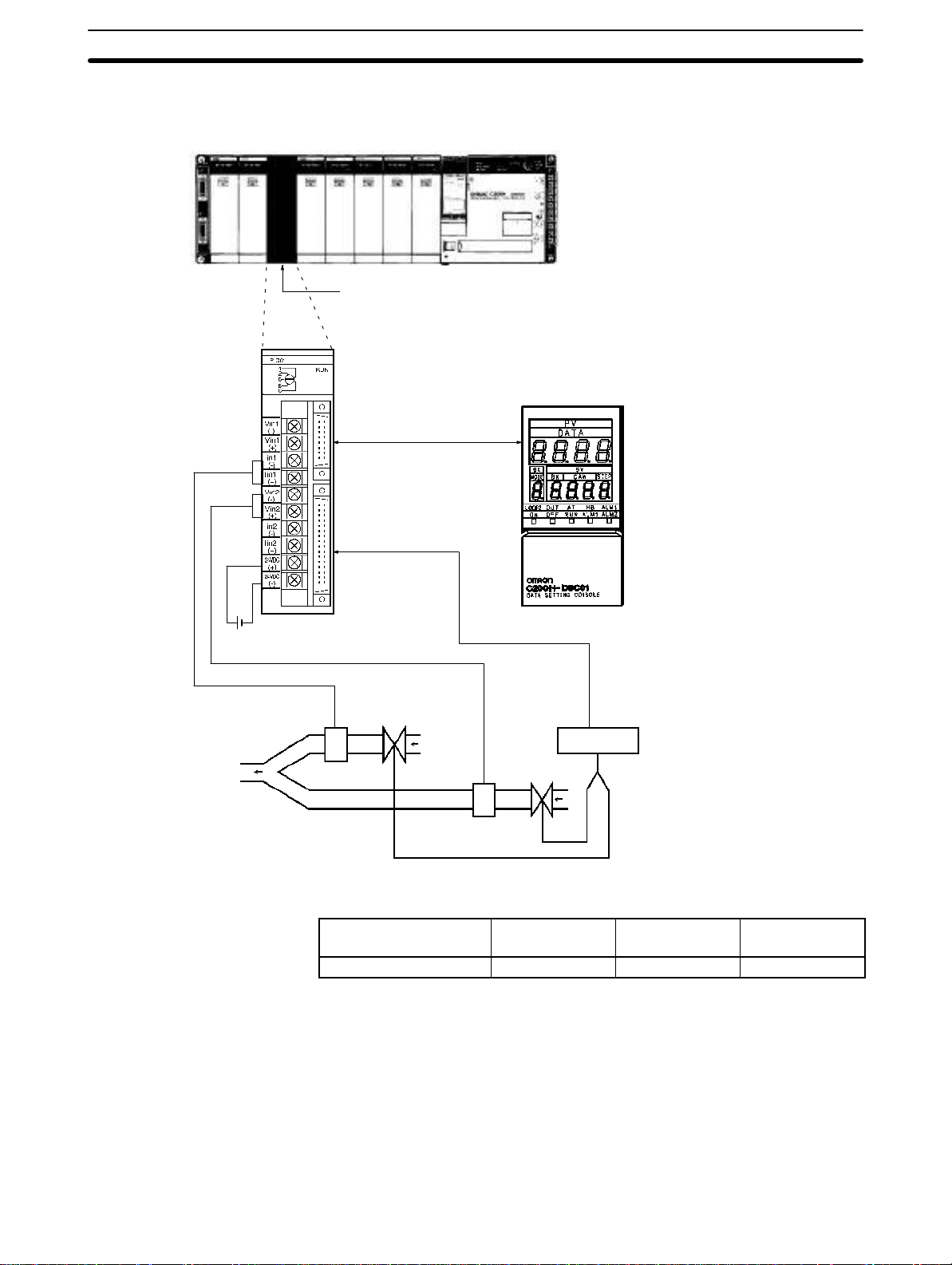
1-2 Basic System Configuration
SYSMAC C200H/C200HS PC
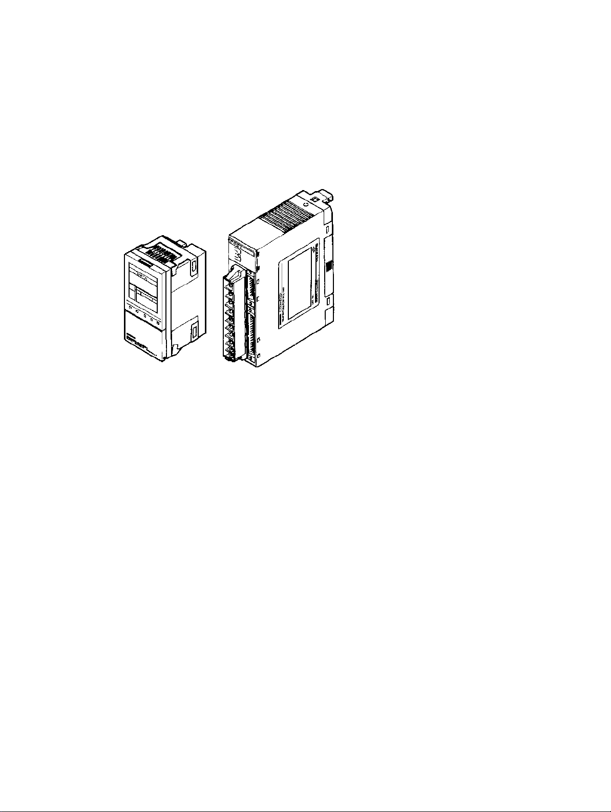
C200H-PID0j
PID Control Unit
Connecting cables:
C200H-CN225 (2 m)
C200H-CN425 (4 m)
Recommended cable:
ES1000-CA021-051 (0.5 m)
ES1000-CA021-102 (1 m)
ES1000-CA021-202 (2 m)
Section 1-2
Data Setting Console
C200H-DSC01
24 VDC
Remote I/O Terminal or
Connector Terminal
Block Converter Unit
(Refer to page 15)
Relay box
Gas
Mixture
Loop 1 Loop 2
Air
Flow sensor
Valve
Flow sensor Valve
PID Control Unit Models
Output type Transistor
output
Model C200H-PID01 C200H-PID02 C200H-PID03
Voltage output Current output
Number of Units The PID Control Unit belongs to the C200H Special I/O Unit group. A maximum
of ten Special I/O Units (including PC Link Units) can be mounted on the CPU
Rack, Expansion I/O Rack, and Slave Rack.
Note Configure the Units such that the maximum current supplied for each Rack is
greater than or equal to the total current consumption for the Units.
Refer to the
C200H PC Operation Manuals
for details on configuring systems.
Number of Units Mountable
on Slave Rack
The number of Special I/O Units used with a Slave Rack is limited by data transmission considerations, as shown in the table below. The numbers in the table
3
Page 14

Basic System Configuration
Section 1-2
indicate the maximum number of Units of groups A, B, C, or D which can be used
with a single Slave Rack.
A B C D
High-speed Counter Units
Position Control Units
(NC111/112)
ASCII Unit
Analog I/O Units
ID Sensor Units
Fuzzy Logic Unit
4 units max. 8 units max. 6 units max. 2 units max.
High-density and Mixed I/O
Units
Temperature Control Units
Heat/Cool Temperature
Control Units
PID Control Units
Cam Positioner Unit
Temperature Sensor Units
Voice Unit
Position Control Unit
(NC211)
Note 1. When a combination of Units from groups A, B, C, and D is used, the number
from each group must satisfy both the following equations:
3A + B + 2C + 6D ≤ 12
A + B + C + D ≤ 8
2. Other Units can be added until the total number of units reaches ten. If PC
Link Units are used, the number of Units including the PC Link Units must
not exceed ten.
Precautions The IR area of the C200H Special I/O Unit is allocated according to the setting of
not
the unit number switch on the front panel,
unit is mounted. Refer to
4-1 Memory Allocation
the address of the slot where the
for the allocation of the memory
area.
With the C200 H, leave the two slots next to the CPU free. It is not possible to use
devices connected to the CPU (such as the Programming Console) if these slots
are occupied.
If the C200H Slave Rack is connected to another SYSMAC model Remote I/O
Master Unit, such as the C120, C500, C1000H, or C2000H, it is not possible to
use a Special I/O Unit with the C200H Slave Rack.
WARNING Always turn the C200H power off before connecting or disconnecting a Unit,
Caution Connect thermocouples with the appropriate compensating conductor.
Additional Function
Description of Function
terminal block, or output connector.
Wire I/O leads in separate ducts from power leads to prevent noise problems.
The function described below has been added to products with the following lot
number and later ones.
07 Z 4 O
1994 (last digit of the year)
December (X: October, Y: November, Z: December)
07 (7th day of the month)
RAM Write Commands
• Previous commands allowed reading and writing to the EEPROM only. These
new commands allow writing to the RAM.
• When various settings require frequent rewriting, write to the RAM and, after
confirming the setting values, save the data by writing it to the EEPROM. The
data written to the RAM is deleted when the power is turned off.
4
Page 15

Basic System Configuration
Section 1-2
• List of RAM Write Commands
Parameter Command Write Read
Set point 4 0 Yes No
Execution bank number 4 2 Yes No
Alarm SV 1 4 3 Yes No
Alarm SV 2 4 4 Yes No
Input shift value 4 5 Yes No
Proportional band 4 6 Yes No
Integral (reset) time 4 7 Yes No
Derivative (rate) time 4 8 Yes No
Decimal point position 5 2 Yes No
Scaling lower limit 5 3 Yes No
Scaling upper limit 5 4 Yes No
Control period 5 7 Yes No
Hysteresis 5 8 Yes No
Alarm hysteresis 5 9 Yes No
Digital filter 5 E Yes No
Alarm 1 mode 6 4 Yes No
Alarm 2 mode 6 5 Yes No
5
Page 16

Connections and Settings
This section provides information on the connections and settings of the PID Control Unit.
2-1 Nomenclature 8 . . . . . . . . . . . . . . . . . . . . . . . . . . . . . . . . . . . . . . . . . . . . . . . . . . . . .
2-2 Switch Settings 8 . . . . . . . . . . . . . . . . . . . . . . . . . . . . . . . . . . . . . . . . . . . . . . . . . . . .
2-3 Wiring 12 . . . . . . . . . . . . . . . . . . . . . . . . . . . . . . . . . . . . . . . . . . . . . . . . . . . . . . . . . . .
2-3-1 Input Wiring 12 . . . . . . . . . . . . . . . . . . . . . . . . . . . . . . . . . . . . . . . . . . . . .
2-3-2 Output Wiring 13 . . . . . . . . . . . . . . . . . . . . . . . . . . . . . . . . . . . . . . . . . . . .
2-3-3 Data Setting Console Cables 16 . . . . . . . . . . . . . . . . . . . . . . . . . . . . . . . . .
SECTION 2
7
Page 17
Switch Settings
2-1 Nomenclature
C200H-PID0j
Section 2-2
Front Panel
Model label
Cover
RUN indicator
SW2
(Switching memory contents
and setting direction under
the cover)
SW1
(Unit number setting)
Data Setting Console
connector
Output connector
Input terminal block
Rear Panel
SW202
(Input type setting)
SW203
(Operation and function settings)
Rack connector
Indicators
RUN Lit when the PID Control Unit is operating normally.
2-2 Switch Settings
The function and setting of switches are identical for all models, except for
SW202.
Unit Number
SW1 Unit number setting
4
2
0
8
6
The addresses are allocated as shown in the following table according to the
Unit number setting.
(3)
(1)
(9)
(5)
(7)
The cut-out indicates the selected position. Negative numbers
are not indicated. Turn the switch with a flat-blade screwdriver.
Turn the switch until it clicks in position. Do not leave the switch
between two settings.
8
Page 18
Switch Settings
Section 2-2
Unit no.
setting
0 Wd 100 to 109
1 Wd 1 10 to 119
2 Wd 120 to 129
3 Wd 130 to 139
4 Wd 140 to 149
5 Wd 150 to 159
6 Wd 160 to 169
7 Wd 170 to 179
8 Wd 180 to 189
9 Wd 190 to 199
Allocated address
The switch is factory-set to 0.
Note If the Unit number is set to an existing Unit number, an alarm occurs and the
C200H does not operate.
Turn the C200H power off before setting the Unit number. If the setting is
changed with the power on, the new setting is not valid until the power is turned
off and back on again.
Switching Memory Contents and Setting Direction
SW2 Switching memory contents and setting direction
Remove the cover and set the switch with the tip of a ballpoint pen or similar object.
Switch no. Pin 1 Pin 2
Function Switching memory contents Setting direction
ON Normal C200H PC
OFF Fixed Data Setting Console
The new setting is valid immediately after the switch setting is changed.
Removing and Attaching the Cover
1
2
ON
OFF
Removing the Cover Attaching the Cover
OFF
Insert a small flat-blade screwdriver between the case and
the cover at the top of the Unit
and lever off the cover.
Place the right edge of the
cover against the case and
press into position.
Switching Memory Contents The contents of the allocated memory differ according to the Unit number set-
ting.
9
Page 19
Switch Settings
Section 2-2
Normal Parameters can be designated as required using
Fixed Parameters are allocated in advance.
Refer to
4-1 Memory Allocation
commands (Refer to
for details of the memory contents.
4-1 Memory Allocation
).
Setting Direction Selects whether the data settings are made from the Data Setting Console or
from the C200H PC, using a user program or Programming Console.
Executed Bank Number
The setting of the executed bank number is made from the C200H PC, regardless of the ON/OFF setting of this switch.
Input Type
SW202 Input type setting
3
2
4
1
0
5
9
6
7
8
Switch number Loop 1 Loop 2
0 4 to 20 mA 4 to 20 mA
1 1 to 5 V 1 to 5 V
2 0 to 5 V 0 to 5 V
3 0 to 10 V 0 to 10 V
4 4 to 20 mA 1 to 5 V
5 4 to 20 mA 0 to 5 V
6 4 to 20 mA 0 to 10 V
7 1 to 5 V 0 to 5 V
8 1 to 5 V 0 to 10 V
9 0 to 5 V 0 to 10 V
The switch is factory-set to 0.
The selected position is shown by the arrow. Turn the switch with a small flat-
blade screwdriver.
The permissible setting range for measurement is –999 to 9999 (EU).
Operation and Function Setting
SW203 Operation and Function Setting
10
134562
NO
OFF ON
Page 20

Switch Settings
Pin no. Function OFF ON
6 Loop 2
Input approximation
5 Loop 1
Input approximation
4 Loop 2 Enabled Disabled or not used
3 SP write mode EEPROM and RAM RAM
2 Control action Reverse Normal
1 Control method PID control ON/OFF control
Straight line Square root
Straight line Square root
Section 2-2
approximation
approximation
The switch is factory-set to OFF.
Input Approximation Set each loop to either straight line (no approximation) or square root approxi-
mation.
Loop 2 Set to “enabled” to use input loop 2, or to “disabled” to use only input loop 1. It is
not possible to use only input loop 2.
Note Always set this switch to the ON (disabled) position when input loop 2 is not
used. A sensor error occurs if this switch is set to the OFF (enabled) position
when no temperature sensor is connected to loop 2.
SP Write Mode This setting selects the SP storage memory. Set it to ON or use RAM Write com-
mands if the writing is to be frequently changed.
Display Units Selects whether setting and SVs displayed on the Data Setting Console are in
Celsius or Fahrenheit.
Control Action Reverse:
The output is increased when the measured temperature is below the SP (i.e., a
negative temperature difference).
Normal:
The output is increased when the measured temperature is above the SP (i.e., a
positive temperature difference).
Control Method Selects the method of control.
11
Page 21
Wiring
2-3 Wiring
2-3-1 Input Wiring
C200H-PID0j
Section 2-3
Voltage input
Loop 1
Current input
Voltage input
Loop 2
Current input
24 VDC
0.2 A
The 24-VDC output from the C200H
CPU or the Power Supply Units is
convenient.
Terminal no. T erminal name
A0 Vin (–) Loop 1
A1 Vin (+)
A2 lin (–)
A3 lin (+)
A4 Vin (–) Loop 2
A5 Vin (+)
A6 lin (–)
A7 lin (+)
A8 24 VDC
A9 GND
A0
A1
A2
A3
A4
A5
A6
A7
A8
A9
Refer to the
table below.
Input Wiring Precautions
1, 2, 3...
12
1. The PID Control Unit will not operate correctly if the SW202 setting does not
match the type of inputs that are connected. In addition, each loop can be
connected to either voltage inputs or current inputs, but not to both. For example, if Loop 1 is set for voltage input, then current input will not work.
2. If no input lead is connected to Loop 2, turn SW203-4 on the rear of the Unit
ON to disable Loop 2. A sensor error occurs if this switch is set to the OFF
(enabled) position when no sensor is connected to Loop 2.
3. Be sure to wire the polarity correctly for each input.
4. Wire I/O leads in separate ducts from power leads to prevent noise problems.
5. A voltage of 24 VDC is used for the voltage output, current output and Data
Setting Console power supply.
6. The terminal block is removable. Make sure that it is attached correctly after
the input wiring connections are completed.
Page 22

Wiring
Section 2-3
Terminal Block
Connections
Use crimp terminals for wiring. T ake care not to overtighten the terminal screws.
Tighten the screws to a torque of 0.8 N S m.
Crimp Terminals
The screws on the terminal block are M3.5 self-rising terminal screws. Use the
following types of M3.5 crimp terminals.
7 mm max.
7 mm max.
Soldered Lead
Strip insulation from 7 to 10 mm at the end of the wire and carefully solder the
lead.
2-3-2 Output Wiring
Connection Diagrams
C200H-PID01 Transistor Output
7 to 10 mm
+
10
24 VDC 24 VDC
NC: Not connected
The pairs of terminals B2 to A2 and B1 to A1 are shorted internally. Always supply power to the 24-VDC terminal (B1) as this drives the internal circuits.
13
Page 23

Wiring
C200H-PID02/PID03 Voltage/Current Output
Circuit Diagrams
C200H-PID01 Transistor Output
Section 2-3
C200H-PID02 Voltage Output
C200H-PID03 Current Output
24 VDC
OUT
Internal circuits
COM
OUT (+)
OUT (–)
Internal circuits
14
Internal circuits
OUT (+)
OUT (–)
Page 24

Wiring
Section 2-3
Applicable Connectors The following connector set manufactured by Fujitsu is included with the Unit:
FCN-361J032-AU (soldering connector)
FCN-360C032-B (cover)
Connector Wiring
Precautions
Connection Precautions
After soldering the lead to each pin, insulate with heat-shrink tube to prevent
shorting with the adjacent terminal.
Tighten the screws after inserting the connector into the Unit. Push the connector firmly into the Remote I/O Terminal or Connector Terminal Block Converter
Unit until it fully locks.
Output Cable The output cables in the table below are recommended.
Model Cable length (L)
ES1000-CA021-051 50 cm
ES1000-CA021-102 1 m
ES1000-CA021-202 2 m
32-pin connector
(manufactured by Fujitsu)
FCN-361J032-AU
63
L
20-pin connector
(manufactured by OMRON)
XG4M-2030
30
Wiring Diagrams
Pin no. Wire no. Pin no. Wire no.
B16
B15
B14
B13
B12
B11
B10
B9
B8
B7
B6
B5
B4
B3
B2
B1
28
46
32-pin connector 20-pin connector
Pin no. Wire no. Pin no. Wire no.
1
2
3
4
5
6
7
8
9
10
Note The pin numbers of the 20-pin con-
nector are marked for convenience.
Refer to them from the ∆ mark.
#1
#2
#3
#4
#5
#6
#7
#8
#9
#10
A16
A15
A14
A13
A12
A11
A10
A9
A8
A7
A6
A5
A4
A3
A2
A1
#11
#12
#13
#14
#15
#16
#17
#18
#19
#20
16.1
#1
#2
#3
#4
#5
#6
#7
#8
#9
#10
11
12
13
14
15
16
17
18
19
20
#11
#12
#13
#14
#15
#16
#17
#18
#19
#20
Note Pins A11 through A16 and B11
through B16 are not connected.
15
Page 25

Wiring
Section 2-3
Remote I/O Terminal The Remote I/O Terminal in the table below is recommended for transistor out-
put.
Model Specification Relays used
G7TC-OC08 Common (+) 8 x G7T-1112S (max. resistive load: 220 VAC, 2A)
Note One P7TF-OS08 I/O Terminal and two G7T-1112S Relays may be
purchased separately and used.
Wiring Diagram External View
24 VDC
Connector Terminal Block
Converter Unit
The Connector Terminal Block Converter Units in the table below are recommended for voltage output and current output type.
Model Terminal screw size
XW2B-20G4 M 2.4
XW2B-20G5 M 3.5
External View
2-3-3 Data Setting Console Cables
Connecting Cable Use the connecting cables in the table below (sold separately) to connect the
Unit to the Data Setting Console.
16
Model Cable length (L)
C200H-CN225 2 m
C200H-CN425 4 m
L
39
17.5
10
17.3
16.1
Page 26

Wiring
Connection Precautions
1, 2, 3...
Section 2-3
1. Tighten the lock screws after inserting the connector into the Unit.
2. Push the connector firmly into the Data Setting Console until the clips fully
lock.
3. The Data Setting Console uses power from input terminals A8 and A9 of the
PID Control Unit, supplied through the connecting cable.
4. Install the supplied connector cover when the Data Setting Console is not
used.
17
Page 27

SECTION 3
Data Setting Console Operation
This section provides the basic operating procedures of the Data Setting Console including parameter settings and displays.
3-1 Operating Procedure 20 . . . . . . . . . . . . . . . . . . . . . . . . . . . . . . . . . . . . . . . . . . . . . . . .
3-2 Data Flow 21 . . . . . . . . . . . . . . . . . . . . . . . . . . . . . . . . . . . . . . . . . . . . . . . . . . . . . . . .
3-3 Nomenclature and Features 22 . . . . . . . . . . . . . . . . . . . . . . . . . . . . . . . . . . . . . . . . . .
3-3-1 Nomenclature 22 . . . . . . . . . . . . . . . . . . . . . . . . . . . . . . . . . . . . . . . . . . . .
3-3-2 Features 23 . . . . . . . . . . . . . . . . . . . . . . . . . . . . . . . . . . . . . . . . . . . . . . . . .
3-4 Parameter Displays and Settings 24 . . . . . . . . . . . . . . . . . . . . . . . . . . . . . . . . . . . . . .
3-4-1 Table of Parameters 24 . . . . . . . . . . . . . . . . . . . . . . . . . . . . . . . . . . . . . . . .
3-4-2 How to Display and Set Parameter Data 25 . . . . . . . . . . . . . . . . . . . . . . . .
19
Page 28

Operating Procedure Section 3-1
3-1 Operating Procedure
After preparing the C200H PC, follow the procedure below to use the PID Control Unit.
1, 2, 3...
1. Set the switches on the front and rear panels according to the operating conditions. (Refer to
Set SW2-2 under the display cover to the OFF position to enable data setting from the Data Setting Console.
2. Mount to Rack.
Turn off the C200H power supply before mounting or dismounting the
C200H on the Rack.
3. Connect the input wiring. (Refer to
The 24-VDC power supply must be connected. The Data Setting Console
will not operate unless the 24-VDC power supply is connected. The sensors
can be connected immediately before the system is tested.
4. Connect the Data Setting Console. (Refer to
Cables
5. Turn on the 24-VDC and the C200H power supplies.
Set the C200H to PROGRAM mode.
6. Use the Data Setting Console to make the settings for the parameters that
need to be changed. (Refer to the rest of this section.)
7. Test operation and adjust data. (Refer to the rest of this section.)
Connect the output wiring and turn on the heater power . To start the test op-
eration, turn ON the RUN bit of the loop that is to be controlled with a device
such as the Programming Console. Monitor the control conditions and adjust the data until the required control is achieved. During operation, the
“bank no.” is switched to “executed bank no.” and cannot be changed from
the Data Setting Console. To change it, use a device such as the Programming Console, or else use the user program.
8. Create the user programs. (Refer to
Programming.
Arrange the data for the test operation, and create the user programs for
data setting, monitoring, switching the bank number, and so on. Set SW2-2
under the display cover to the ON position to enable data setting from the
C200H PC.
9. Start operation.
.)
2-2 Switch Settings.
)
)
2-3 Wiring.
Section 4 PC Memory Allocation and
)
2-3-3 Data Setting Console
20
Page 29

Data Flow
3-2 Data Flow
Section 3-2
The data flow in the PID Control Unit is shown in the diagram below.
Read
PID Control Unit
Write executed bank no.
Write
Read
ON
SW2-2
OFF
C200H PC
Data Setting Console
The read operation and setting the executed bank number are possible from a
user program or from a device, such as the Programming Console, regardless of
the ON/OFF setting of SW2-2.
Data written from the Data Setting Console and data written with the EEPROM
write commands when SW2-1 (switching memory contents) is set to Normal are
written to the PID Control Unit EEPROM and are consequently retained when
the power supply is turned OFF.
Data written with RAM write commands when SW2-1 (switching memory contents) is set to Normal, the SP value set when SW2-1 is set to Fixed, and
executed bank number settings made from the C200H PC are written directly to
RAM and are not saved to EEPROM. This data is lost when the power supply is
turned OFF.
Data Settings from Data
Setting Console
Set SW2-2 under the display cover to the OFF position to enable data setting
from the Data Setting Console.
The “bank no.” can be set when operation is stopped (i.e., when the RUN bit is
OFF). During operation it is switched to “executed bank no.” and cannot be
changed from the Data Setting Console. To change the executed bank number,
use a user program or a device such as the Programming Console.
Operation begins when the RUN bit of the output relay turns ON. (For information on output relays, refer to
.
ming
Section 4 PC Memory Allocation and Program-
21
Page 30

Nomenclature and Features
3-3 Nomenclature and Features
3-3-1 Nomenclature
Section 3-3
Display Key
Front View
(With cover open)
Data display
Operation indicators
Display for Cam
Positioner
Cover
Down Key
Up Key
Operation keys
Select parameters
Set data
Switch Loops
Side View
Panel mounting bracket
(Refer to
panel mounting.)
Appendix B Dimensions
Rear View
for details about
Level Key Loop Key
PID Control Unit connector
Connecting cable (sold separately)
C200H-CN225 (2 m)
C200H-CN425 (4 m)
The bottom row of the operation keys have upper and lower labels. The upper
labels apply to PID Control Unit operation. The lower labels are for the Cam Positioner Unit.
Two display sheets are supplied: one for the PID Control Unit and one for the
Cam Positioner Unit. If the Data Setting Console is to be used with the PID Control Unit only, attach the display sheet for the PID Control Unit.
Note The Data Setting Console will not operate unless a 24-VDC power supply is con-
nected to the PID Control Unit input terminals.
22
Page 31

Nomenclature and Features
3-3-2 Features
Data Display
Note Operation begins when the RUN bit of the output relay turns ON.
Operation Indicators
Section 3-3
Name Function
PV (Process
Value)
SV (Set Value) The display is as follows, according to the PV display contents.
BK (Bank
Number)
Name Function
LOOP2 Indicates whether the displayed settings relate to Loop 1 or Loop
OUT (Output) Turns ON when the output is ON for
AT
(Auto-tuning)
HB (Heater
Burnout)
ALM1 (Alarm) Turns ON to indicate the temperature is in
Displays the PV or the parameter symbol selected with the Level
or Display Key (Refer to next page).
PV (process value): SV (set value) is displayed.
Parameter symbol: Setting/monitor data is displayed.
Displays the bank number of the data presently being displayed.
During operation, the executed bank number is displayed. (See
note)
2. Press the Loop Key and hold down for approximately 2
seconds to switch between Loop 1 and Loop 2.
Indicator OFF: Loop 1
Indicator ON: Loop 2
These indicators
transistor output or voltage output types.
Blinks at approximately 1 second intervals
during auto-tuning.
relate to the
currently displayed
loop.
Turns ON to indicate a heater burnout
alarm.
the alarm range set with Alarm SV 1
(upper- and lower-limit alarm). Refer to the
following page.
Display Patterns
Executed bank number or displayed
bank number
Display Pattern 1 Display Pattern 2
Process
value
Set point
Executed
bank number
or displayed
Indicator OFF: Loop 1
Indicator ON: Loop 2
bank number
Indicator OFF: Loop 1
Indicator ON: Loop 2
Parameter symbol
SV (Set value)
Monitored value
Execution status
23
Page 32

Parameter Displays and Settings
Operation Keys
Level Key The parameter items are divided into three display groups (Refer
Display Key Press this key to select the required parameter from the selected
Section 3-4
Name Function
to display levels 0 to 2 in the table below). Press this key to
switch from one group to another. The display levels
automatically cycle in the sequence 0 –> 1 –> 2 –> 0 when the
key is held down for approximately 2 seconds.
display level 0 to 2 (Refer to table below).
The parameters cycle automatically when the key is held down.
Loop Key Press this key for approximately two seconds to switch between
Up Key Press this key to increment SV.
Down Key Press this key to decrement an SV.
Loop 1 and Loop 2.
The SV increment continuously while the key is held down. The
SV display blinks when the value reaches its upper limit.
The SV decreases continuously while the key is held down. The
SV display blinks when the value reaches its lower limit.
3-4 Parameter Displays and Settings
3-4-1 Table of Parameters
Display
level
0
Parameter Display
PV monitor
(see note 3)
Manual output
volume
(see note 6)
Set point (see
note 3)
Bank number
Alarm SV 1 (see
notes 3, 4)
Alarm SV 2 (see
notes 3, 4)
Input shift value
(see note 3)
Proportional band
(see note 1)
Integral (reset)
time (see note 1)
Derivative (rate)
time (see note 1)
symbol
---
---
bk
al–1
al–2
in–5
Write Read Loop
no.
No Yes Yes No Scaling lower
Yes Yes Yes No -5 to 105% 0% 26
o
Yes Yes Yes Yes Scaling lower
See
note 5
Yes Yes Yes Yes
Yes Yes Yes Yes
Yes Yes Yes Yes –999 to 9999 0 EU 27
Yes Yes Yes Yes 0.0 to 999.9% FS 10.0% FS
p
Yes Yes Yes Yes 0 to 9999 s 240 s
i
Yes Yes Yes Yes 0 to 9999 s 40 s
d
Yes Yes No 1 to 8 1 26
Bank
no.
Data range Default value Page
(Unit: EU) 26
limit –10% to
scaling upper
limit +10%
0 EU 26
limit to scaling
upper limit
Alarm mode
1, 4, 5:
0 to 9999
Other:
–999 to 9999
0 EU 27
27
24
Page 33

Parameter Displays and Settings
Section 3-4
Display
level
1
2 Control output
Parameter
Decimal point
position
Scaling lower limit
Scaling upper limit
Digital filter
Control period
(see note 1)
Hysteresis (see
note 2)
Alarm hysteresis
(see note 4)
variable monitor
Auto-tuning start/
stop (see note 1)
Copy bank
Input-type monitor
Alarm 1 mode
Alarm 2 mode
symbol
dp
inl
inh
df
cp
hys
hysa
bcpy
in-t
alt1
alt2
ReadWriteDisplay
Yes Yes Yes No 0 to 3 1 28
Yes Yes Yes No -999 to (scaling
Yes Yes Yes No (Scaling lower
Yes Yes Yes No 0 to 100 s 0 s 28
Yes Yes Yes No 1 to 99 s 20 s 29
Yes Yes Yes Yes 0.0 to 100.0% FS 0.2% FS 29
Yes Yes Yes No 0.0 to 100.0% FS 0.1% FS 29
No Yes Yes No 0.0 to 100.0% 0.0% 30
o
Yes Yes Yes No --- --- 30
at
Yes Yes Yes No --- --- 30
No Yes No No 0 to 9 Setting for
Yes Yes Yes No 0 to 9 2 31
Loop
no.
no.
0 28
upper limit – 1
digit)
1000 28
limit + 1) to 9999
SW202
PageDefault valueData rangeBank
31
Yes: Possible.
No: Not possible or not required.
Note 1. Only when advanced PID control is selected. (Switch 203-1 = OFF)
2. Only when ON/OFF control is selected. (Switch 203-1 = ON)
3. The decimal point position is set by the “decimal point position” parameter.
4. Does not apply when Alarm Mode = 0.
5. Writing is not possible during operation (i.e., when RUN is ON).
6. Only when the output relay “MAN” bit = 1.
3-4-2 How to Display and Set Parameter Data
Basic Operation
When not specifically explained, use the keys as described below.
Changing the Display Level
When the Level Key is pressed, the leading parameter for each level is displayed.
Changing Parameters
When the Display Key is pressed, the parameters are displayed in order. There
may be skips depending on the model and DIP switch settings.
Changing the SV
Pressing the Up Key or the Down Key changes the SV. The SV is retrieved automatically.
Changing the Loop
The loop is changed each time the Loop Key is pressed. It can be confirmed by
means of the LOOP 2 indicator.
25
Page 34

Parameter Displays and Settings
Manual Output Volume (Display Level 0)
Section 3-4
PV and SV (Display Level 0)
PV
SV
Process value (monitored every 100 ms)
Manual output volume of currently selected loop (Unit: %)
Parameter signal of manual output volume
Settings
• This is used to manually manipulate the output volume. It is valid when the output relay “MAN” bit is ON.
• The “MAN” bit can be turned ON and OFF by means of a device such as the
Programming Console, or by means of the user program. For details, refer to
Section 4 PC Memory Allocation and Programming
PV
SV
Process value (monitored every 100 ms)
Set point of currently selected bank and loop (unit:EU)
.
Bank Number (Display Level 0)
PV
SV
Valid SV Range
Set the set point in the range between the scaling lower limit and the scaling upper limit.
Error Display
When a sensor error occurs, one of the codes below and the detected temperature blink alternately in the PV display.
ser1
ser2
Bank number parameter symbol
Currently set bank number.
During control operation: Executed bank number
Control operation interrupted: Currently displayed bank number
The analog input is out of the range: (input measurement range +
10%FS). That is, 10%FS below the lower limit or 10%FS above
pp
the upper limit. Includes broken or incorrect input wiring.
ser1 : Loop1 or Loop1 and Loop2 simultaneously.
ser2 : Loop2
p
Settings
• The bank number can be changed.
• The changed SV is reflected in the bank number display (BK).
Bank Number and Executed Bank Number
The executed bank number cannot be changed from the Data Setting Console.
When changing these parameters from the Data Setting Console, stop operation. While operation is stopped, the bank number setting can be changed.
26
Page 35

Parameter Displays and Settings
Alarm SV 1 (Display Level 0)
Section 3-4
Alarm SV 2 (Display Level 0)
Input Shift Value (Display Level 0)
If the displayed value differs from the actual value due to the sensor position or
some other conditions, set the input shift value such that the correct value is displayed.
PV
SV
Invalid if ALARM mode = 0.
PV
SV
Invalid if ALARM mode = 0.
PV
SV
Alarm 1 parameter symbol
Alarm SV of currently selected bank and loop (unit: EU)
Alarm 2 parameter symbol
Alarm SV of currently selected bank and loop (unit: EU)
Input shift value parameter symbol
Input shift value of currently selected bank and loop (unit:
EU)
Proportional Band (Display Level 0)
PV
SV
• This sets the proportional band. It is valid only when SW203-1 is set to OFF
(i.e., PID control).
• This value is reflected even when auto-tuning (AT) is executed.
• If this value is set to “0.0,” ON/OFF control is executed with PID control se-
lected.
Integral (Reset) Time (Display Level 0)
PV
SV
• This sets the integral time. It is valid only when SW203-1 is set to OFF (i.e., PID
control).
• This value is reflected even when auto-tuning (AT) is executed.
Derivative (Rate) Time (Display Level 0)
Proportional Band parameter symbol
Proportional band of currently selected bank and loop
(unit: %FS)
Integral time parameter symbol
Integral time of currently selected bank and loop
(unit: second)
PV
SV
Derivative time parameter symbol
Derivative time of currently selected bank and loop
(unit: second)
27
Page 36

Parameter Displays and Settings
• This sets the integral time. It is valid only when SW203-1 is set to OFF (i.e., PID
control).
• This value is reflected even when auto-tuning (AT) is executed.
Decimal Point Position (Display Level 1)
Section 3-4
PV
SV
The decimal point position setting applies to the following parameters:
PV monitor, SV, alarm SV, and input shift value.
Scaling Lower Limit (Display Level 1)
PV
SV
This sets the scaling lower limit. The default value is 0%.
Scaling Upper Limit (Display Level 1)
PV
SV
Decimal point position parameter symbol
Decimal point position of currently selected loop
Scaling lower limit parameter symbol
Scaling lower limit of currently selected loop
Scaling upper limit parameter symbol
Scaling upper limit of currently selected loop
Digital Filter (Display Level 1)
This sets the scaling upper limit. The default value is 1000%.
PV
SV
Digital filter parameter symbol
Time constant of currently selected loop (unit: seconds)
This delays the response to sudden input changes. The SV is designated by “T”
in the illustration below.
Input
After Passing Through the Filter of Set Value “T”
100%
63%
0
T0
(s)
→
28
Page 37

Parameter Displays and Settings
Control Period (Display Level 1)
Section 3-4
Hysteresis (Display Level 1)
PV
SV
Control period parameter symbol
Control period of currently selected loop
(Unit: seconds)
• This sets the control period. It is valid when SW203-1 is OFF (PID control).
• The control period is the time required to complete one transistor output or volt-
age output ON/OFF cycle.
ON
OFF
ON time
Control period
PV
SV
Hysteresis parameter symbol
Hysteresis of currently selected bank and loop
(Unit: %FS)
• Hysteresis prevents control output chattering and eliminates noise influences.
• When switching from ON to OFF, operation proceeds at the set point. When
switching from OFF to ON, operation proceeds at a lower point determined by
the hysteresis SV, as shown in the illustration below.
Hysteresis is applied in the following situations.
• When ON/OFF control is selected (i.e., when SW203-1 is ON).
• When advanced PID control is selected (i.e., when SW203-1 is OFF) and P
(proportional band) is 0.
Alarm Hysteresis (Display Level 1)
PV
SV
Hysteresis
ON
OFF
Set point
Alarm hysteresis parameter symbol
Alarm hysteresis of currently selected loop
(Unit: %FS)
• Alarm hysteresis prevents alarm output chattering and eliminates noise influences. It is invalid when both ALARM mode 1 and ALARM mode 2 are set to
“0.”
• When switching from OFF to ON, operation proceeds at the set point. When
switching from ON to OFF, a hysteresis SV operating band is provided which
29
Page 38

Parameter Displays and Settings
may be either higher or lower than the set point, depending on the ALARM
mode.
Section 3-4
Upper Limit Mode Lower Limit Mode
Hysteresis
OFF
Alarm SV Alarm SV
The alarm output is OFF if the present value lies within the hysteresis band when
the Unit is turned on.
Control Output Variable Monitor (Display Level 2)
PV
SV
The relationship between the control output variable and control period is defined by the formula below:
Control output variable (%) = x 100
The control output variable during ON/OFF control (when SW203-1 on the rear
panel is ON) is ON = 100% and OFF = 0%.
Auto-tuning Start/Stop (Display Level 2)
ON
Hysteresis
ON
OFF
Control output variable monitor parameter symbol
Control output variable of currently selected loop
(Unit: %) Monitored every 100 ms.
ON time
Control period
PV
SV
AT start/stop parameter symbol
Copy Bank (Display Level 2)
PV
SV
Copy bank parameter symbol
Process value
Set point
AT indicator blinks
• The auto-tuning operation begins when the Up Key is pressed. The PV and SV
return to the respective present value and set point displays. While auto-tuning
is in progress the AT indicator blinks.
• To interrupt, press the Level and Display Keys again to display at. When at
appears, press the Up Key. When the interrupt is executed, the A T display disappears and the process value is displayed.
• When auto-tuning is completed, the AT indicator stops blinking and the P, I, a nd
D data is written to EEPROM.
Execute bank copy
Bank being copied
Bank copy completed
• When the Up Key is pressed, the data other than the set point is copied from
bank number 1 to banks 2 through 8.
• Use this method to create data in banks 2 through 8 by slightly modifying the
data in bank number 1.
30
Page 39

Parameter Displays and Settings
Input-type Monitor (Display Level 2)
Section 3-4
PV
SV
Note Cannot be set.
Alarm 1 and Alarm 2 Modes (Display Level 2)
PV
SV
PV
SV
Select the desired alarm type from the following chart and set the number (X: set
value)
ALARM
mode
0No alarm
Input-type monitor parameter symbol
SW202 set value
Alarm 1 Mode parameter symbol
Alarm 1 Mode of currently selected loop
Alarm 2 Mode parameter symbol
Alarm 2 Mode of currently selected loop
Alarm Type Alarm Range
0SP
1 Upper- and lower-limit alarm
2 Upper-limit alarm
3 Lower-limit alarm
4 Upper- and lower-limit range alarm
5 Upper- and lower-limit alarm with
standby sequence
6 Upper-limit alarm with standby
sequence
7 Lower-limit alarm with standby
sequence
8 Absolute-value upper-limit alarm
9 Absolute-value lower-limit alarm
x x
x
x
x x
x x
x
x
x
x
Standby Sequence
When the power is turned on, the value is below the set point, so alarm output
status occurs with regard to the lower limit alarm. In this situation, if “lower limit
31
Page 40

Parameter Displays and Settings
alarm with standby sequence” is selected, the standby sequence recognizes
that the value is out of the alarm range and then outputs an alarm when the value
enters the alarm range once more.
Lower Limit Alarm with Standby Sequence
The standby sequence is restarted in the following situations.
• When the power is turned on.
• When the set point is changed.
• When the executed bank number is changed.
• When the ALARM mode is changed.
• When changing from stop to run.
Hysteresis
OFF point
Alarm SV
0°C
Alarm output
Standby sequence
cancel point
Section 3-4
32
Page 41

SECTION 4
PC Memory Allocation and Programming
This section provides the C200H PC’s memory allocation for the PID Control Unit. Basic programming procedures and
examples are also provided.
4-1 Memory Allocation 34 . . . . . . . . . . . . . . . . . . . . . . . . . . . . . . . . . . . . . . . . . . . . . . . .
4-1-1 Memory Allocation Table 35 . . . . . . . . . . . . . . . . . . . . . . . . . . . . . . . . . . .
4-1-2 Memory Contents 36 . . . . . . . . . . . . . . . . . . . . . . . . . . . . . . . . . . . . . . . . .
4-1-3 Table of Commands 40 . . . . . . . . . . . . . . . . . . . . . . . . . . . . . . . . . . . . . . . .
4-2 Data Flow 42 . . . . . . . . . . . . . . . . . . . . . . . . . . . . . . . . . . . . . . . . . . . . . . . . . . . . . . . .
4-3 Programming 42 . . . . . . . . . . . . . . . . . . . . . . . . . . . . . . . . . . . . . . . . . . . . . . . . . . . . .
4-3-1 Example with SW2-1 in the Fixed Position 42 . . . . . . . . . . . . . . . . . . . . .
4-3-2 Example 1: Write with SW2-1 in the Normal Position 43 . . . . . . . . . . . . .
4-3-3 Example 2: Read with SW2-1 in the Normal Position 46 . . . . . . . . . . . . .
4-3-4 Operation Timing 49 . . . . . . . . . . . . . . . . . . . . . . . . . . . . . . . . . . . . . . . . .
33
Page 42

Memory Allocation Section 4-1
4-1 Memory Allocation
Memory Allocation According to the Unit number switch setting on the front of the C200H PID Con-
trol Unit, 10 words are allocated for each Unit number in the Special I/O Unit IR
area between IR100 to IR199, which is used as the I/O refresh data area. The IR
area used by the C200H PID Control Unit is refreshed on each C200H PC I/O
refresh scan.
C200H PC
IR area
Unit#0 IR100 to IR109
Unit#1 IR110 to IR119
Unit#2 IR120 to IR129
Unit#3 IR130 to IR139
Unit#4 IR140 to IR149
Unit#5
Unit#6 IR160 to IR169
Unit#7 IR170 to IR179
Unit#8 IR180 to IR189
Unit#9 IR190 to IR199
IR150 to IR159
OUT
IN
During PC I/O refresh, each
scan is executed for the outputs (PC to PID Control Unit)
followed by the inputs (PID
Control Unit to PC).
PID Control Unit
I/O refresh data area
Wd (n)
to
Wd (n+2)
Wd (n+3)
to
Wd (n+9)
(n=100 + 10 x Unit number)
The terms “output” and “input” are defined from the C200H PC side.
Output
refresh
Input
refresh
Note A Duplicate I/O Unit error occurs if the set Unit number corresponds to the num-
ber of an existing Special I/O Unit.
Selecting Allocated Data The data allocated to each IR word due to the Unit number setting is determined
by the setting of SW2-1 on the front of the Unit.
ON Normal All data can be set using commands.
OFF Fixed Parameters are fixed for the set point (SV).
This setting becomes valid immediately when the switch is set.
34
Page 43

number
number
re
Memory Allocation Section 4-1
4-1-1 Memory Allocation Table
SW2-1 in Fixed Position
(n=100 + 10 x Unit number)
I/O Word
Output n
n+1
n+2 Loop 1 executed bank
Input n+3
n+4
n+5
n+6
n+7
n+8 Loop 1 status data
n+9 Loop 2 status data
Bit
15 14 13 12 11 10 09 08 07 06 05 04 03 02 01 00
Loop 1 SP (see note)
0 to 9, F 0 to 9 0 to 9 0 to 9
Loop 2 SP (see note)
0 to 9, F 0 to 9 0 to 9 0 to 9
Loop 2 executed bank
number number
Loop 1 PV (see note)
0 to 9, F 0 to 9 0 to 9 0 to 9
Loop 2 PV (see note)
0 to 9, F 0 to 9 0 to 9 0 to 9
Loop 1 SP (see note)
0 to 9, F 0 to 9 0 to 9 0 to 9
Loop 2 SP (see note)
0 to 9, F 0 to 9 0 to 9 0 to 9
Loop 1 executed bank
number number
0 Sen-
0 Sen-
0 0 0 MAN
sor
error
0 0 0 MAN
sor
error
Loop 2 executed bank
Loop 1 Loop 2
MAN RUN MAN RUN
0 0 0
RUN
0 0 0 Con-
RUN
0 0 0 Con-
0
SW 2
2 1
AT 0 AL1 AL2
trol
output
AT 0 AL1 AL2
trol
output
SW2-1 in Normal Position
I/O Word
15 14 13 12 11 10 09 08 07 06 05 04 03 02 01 00
Output
Input n+3
n Read/write instruction
Read/write Loop no. Bank no. Instruction
n+1
n+2 Loop 1 executed bank
Write data (see note)
0 to 9, F 0 to 9 0 to 9 0 to 9
Loop 1 PV (see note)
0 to 9, F 0 to 9 0 to 9 0 to 9
Note Four digits BCD and the decimal point position are designated by the “decimal
point position” parameter. The most significant digit (F) = minus (–).
(n=100 + 10 x Unit number)
Bit
Loop 2 executed bank
Loop 1 Loop 2
MAN RUN MAN RUN
0 0 Write
-
-
quest
35
Page 44

N
ified
Wd
aue
Memory Allocation Section 4-1
I/O BitWordI/O
Word
00010203040506070809101112131415
Input n+4
n+5
n+6 0 Write
n+7
n+8 Loop 1 status data
n+9 Loop 2 status data
Loop 2 PV (see note)
0 to 9, F 0 to 9 0 to 9 0 to 9
Read data (see note)
0 to 9, F 0 to 9 0 to 9 0 to 9
error
Loop 1 executed bank
number number
0 Sen-
0 Sen-
0 0 0 MAN
sor
error
0 0 0 MAN
sor
error
Loop 2 executed bank
0 0 Write
0 0 0 0 Read
complete
0 0 0
RUN
0 0 0 Con-
RUN
0 0 0 Con-
AT 0 AL1 AL2
trol
output
AT 0 AL1 AL2
trol
output
com-
plete
SW2
2 1
Note Four digits BCD and the decimal point position are designated by the “decimal
point position” parameter. The most significant digit (F) = minus (–).
4-1-2 Memory Contents
SW2-1 in Fixed Position
I/O Address Data item Data contents
Word Bit
Output n 15 to 00 Loop 1 SP
n+1 15 to 00 Loop 2 SP
n+2 15 to 12 Loop 1
executed
bank
number
11 to 08 Loop 2
executed
bank
number
07 Loop 1
MAN
06 Loop 1
RUN
05 Loop 2
MAN
04 Loop 2
RUN
03 to 00 --- Not used. Set to 0.
Sets the Loop 1 and Loop 2 SP (set point) as 4-digit BCD data.
Set the most significant digit to F for minus (–).
oteThese spec
(n+2) and can are written directly to RAM. (Refer to
gramming.
Sets the bank number executed for Loop 1 and Loop 2 as 1-digit
BCD data. Set executed bank numbers from 1 to 8. If the value is
set out of this range, the bank number reverts to the previous
value.
This is the Loop 1 Manual Output Mode bit. When it is set to 1,
the Unit goes into Manual Output Mode.
This is the Loop 1 Run/Stop bit. When it is set to 1, operation
starts; when it is set to 0, operation stops.
This is the Loop 2 Manual Output Mode bit. When it is set to 1,
the Unit goes into Manual Output Mode.
This is the Loop 2 Run/Stop bit. When it is set to 1, operation
starts; when it is set to 0, operation stops.
p
values apply to the bank number set with
)
(n=100 + 10 x Unit number)
pp
4-3 Pro-
36
Page 45

gg ()
()g
Memory Allocation Section 4-1
I/O Data contentsData itemAddress
BitWord
Input n+3 15 to 00 Loop 1 PV
n+4 15 to 00 Loop 2 PV
n+5 15 to 00 Loop 1 SP
n+6 15 to 00 Loop 2 SP
n+7 15 to 12 Loop 1
executed
bank
number
11 to 08 Loop 2
executed
bank
number
07 to 02 --- Not used. Each bit is set to 0.
01 SW2-2 Outputs the ON/OFF status of SW2-2 (setting direction).
00 SW2-1 Outputs the ON/OFF status of SW2-1 (switching memory
n+8 Loop 1
n+9 Loop 2
15 --- Not used. Set to 0.
14 Sensor
error
13 to 10 --- Not used. Each bit is set to 0.
09 MAN ON (set to 1) for Manual Output Mode.
08 RUN ON (set to 1) during operation.
07 to 05 --- Not used. Each bit is set to 0.
04 Control
output
03 AT Bit set to 1 during auto-tuning (AT).
02 --- Not used. Set to 0.
01 AL1
00 AL2
Outputs the Loop 1 and Loop 2 PV (process value) as 4-digit
BCD data. The most significant digit is F for minus (–).
Outputs the Loop 1 and Loop 2 SP (set point) as 4-digit BCD
data. The most significant digit is F for minus (–).
Outputs the bank number currently executed for Loop 1 and Loop
2 as 1-digit BCD data.
0: Data Setting Console
1: C200H PC
contents).
0: Fixed
1: Normal
Loop 1/2
status data
Bit set to 1 if the sensor is not connected, a sensor
wire is broken, or the input data exceeds the
operational temperature range.
Bit set to 1 when the control output (transistor or
voltage output) is ON.
Bit set to 1 when the value enters the set alarm
range. (Refer to page 23.)
SW2-1 in Normal Position
(n=100 + 10 x Unit number)
I/O Address Data item Data contents
Word Bit
Output n 15 and 14 Read/Write The data bit sets operation to read or write.
Write = 01 Read = 00
13 and 12 Loop no. The data bit sets the Loop Number to which the
read or write operation applies.
Loop 1 = 01, Loop 2 = 10
11 to 08 Bank no. Sets the bank number to which the read or write
operation applies as 1-digit BCD data. Set executed
bank numbers from 1 to 8.
07 to 00 Command Sets the command code (Refer to page 40) for the
read or write operation as 2-digit BCD data.
Read/Write
command
37
Page 46

e ous a ue
BCD data. The decimal oint osition is designated by the
Memory Allocation Section 4-1
I/O Data contentsData itemAddress
BitWord
Output n+1 15 to 00 Write data Set the SP for a write operation as 4-digit BCD data. The least
significant digit of the actual data matches the least significant
digit of the set value. Set the most significant digit to F for minus
(–) values. The write operation commences when the write
request flag (Wd (n+2), bit 00 ) turns ON.
n+2 15 to 12 Loop 1
executed
bank
number
11 to 08 Loop 2
executed
bank
number
07 Loop 1
MAN
06 Loop 1
RUN
05 Loop 2
MAN
04 Loop 2
RUN
03 to 01 --- Not used. Set to 0.
00 Write
request
Input n+3 15 to 00 Loop 1 PV
n+4 15 to 00 Loop 2 PV
n+5 15 to 00 Read data Outputs the data read with the commands set with Wd (n). The
n+6 15 to 12 --- Not used. Each bit is set to 0.
11 Write error Bit set to 1 when the write data exceeds the set permissible
10 and 09 --- Not used. Each bit is set to 0.
08 Write
complete
07 to 01 --- Not used. Each bit is set to 0.
00 Read
complete
Set the bank number currently executed for Loop 1 and Loop 2 as
1-digit BCD data. Executed bank numbers are from 1 to 8. If the
value is set out of this range, the bank number reverts to the
previous value.
This is the Loop 1 Manual Output Mode bit. When it is set to 1,
the Unit goes into Manual Output Mode.
This the Loop 1 Run/Stop bit. When it is set to 1, operation starts;
when it is set to 0, operation stops.
This is the Loop 2 Manual Output Mode bit. When it is set to 1,
the Unit goes into Manual Output Mode.
This the Loop 2 Run/Stop bit. When it is set to 1, operation starts;
when it is set to 0, operation stops.
Turn this bit ON to write the data in Wd (n+1), by means of this
command.
Turn this bit OFF after the Write Complete Flag (Wd (n+6), bit 08)
turns ON.
Outputs the Loop 1 and Loop 2 PV (process value) as 4-digit
BCD data. The decimal point position is designated by the
“decimal point position” parameter. Set the most significant digit
to F for minus (–) values.
decimal point position is designated by the “decimal point position
” parameter. Set the most significant digit to F for minus (–)
values.
range. The bit is automatically set to 0 when the Write Request
Flag (Wd (n+2), bit 00) turns OFF.
Bit set to 1 when the write operation executed by means of the
command set with Wd (n) ends normally. The bit is automatically
set to 0 when the Write Request Flag (Wd (n+2), bit 00) turns
OFF.
Bit set to 1 when the read operation executed by means of the
command set with Wd (n) ends normally. The bit is automatically
set to 0 when the next command is set.
38
Page 47

Memory Allocation Section 4-1
I/O Data contentsData itemAddress
BitWord
Input n+7
n+8 Loop 1
n+9 Loop 2
15 to 12 Loop 1
executed
bank
number
11 to 08 Loop 2
executed
bank
number
07 to 02 --- Not used. Each bit is set to 0.
01 SW2-2 Outputs the ON/OFF status of SW2-2 (setting direction).
00 SW2-1 Outputs the ON/OFF status of SW2-1 (switching memory
15 --- Not used. Set to 0.
14 Sensor
error
13 to 10 --- Not used. Each bit is set to 0.
09 MAN ON (set to 1) for Manual Output Mode.
08 RUN ON (set to 1) during operation.
07 to 05 --- Not used. Each bit is set to 0.
04 Control
output
03 AT Bit set to 1 during auto-tuning (AT).
02 --- Not used. Set to 0.
01 AL1
00 AL2
Outputs the bank number currently executed for Loop 1 and Loop
2 as 1-digit BCD data.
0: Data Setting Console
1: C200H PC
contents).
0: Fixed
1: Normal
Loop 1/2
Bit set to 1 if an input is not connected, an input wire
is broken, or the input data exceeds the operational
range.
Bit set to 1 when the control output (transistor or
voltage output) is ON.
Bit set to 1 when the value enters the set alarm
range (Refer to page 23).
status data
39
Page 48

9999
Memory Allocation Section 4-1
4-1-3 Table of Commands
The command codes shown below are set in bits (Wd n) 07 to 00 when the
SW2-1 (switching memory contents) on the front panel is set in the Normal position.
EEPROM Write/Read Commands
Parameter Com-
mand
Set point (see note 3) 0 0 Yes Yes Yes Yes Scaling lower limit to scaling
Manual output volume
(see note 6)
Execution bank number 0 2 Yes Yes Yes No 1 to 8 0001 to
Alarm SV 1 (see notes
3, 4)
Alarm SV 2 (see notes
3, 4)
Input shift value (see
note 3)
Proportional band (see
note 1)
Integral (reset) time
(see note 1)
Derivative (rate) time
(see note 1)
Decimal point position 1 2 Yes Yes Yes No 0 to 3 0000 to
Scaling lower limit 1 3 Yes Yes Yes No -999 to (scaling upper limit
Scaling upper limit 1 4 Yes Yes Yes No (Scaling lower limit + 1 digit)
Control period (see note1)1 7 Yes Yes Yes No 1 to 99 s 0001 to
Hysteresis (see note 2) 1 8 Yes Yes Yes Yes 0.0 to 100.0 0000 to
Alarm hysteresis (see
note 4)
Digital filter 1 E Yes Yes Yes No 0 to 100 0000 to
Control output variable
monitor
Auto-tuning start/stop
(see note 1)
Copy bank 2 2 Yes No Yes No --- --Input-type monitor 2 3 No Yes No No 0 to 9 0000 to
Alarm 1 mode 2 4
Alarm 2 mode 2 5
0 1 Yes Yes Yes No -5 to 105% F005 to
0 3 Yes Yes Yes Yes
0 4 Yes Yes Yes Yes
0 5 Yes Yes Yes Yes –999 to 9999 F999 to
0 6 Yes Yes Yes Yes 0.0 to 999.9 0000 to
0 7 Yes Yes Yes Yes 0 to 9999 s 240 s
0 8 Yes Yes Yes Yes 0 to 9999 s 40 s
1 9 Yes Yes Yes No 0.0 to 100.0 0000 to
2 0 No Yes Yes No –5.0 to
2 1 Yes No Yes No --- AT start =
Write Read Loop
no.
Yes Yes Yes No 0 to 9 0000 to
Bank
no.
Actual data
range
upper limit
Alarm mode
1, 4, 5:
0 to 9999
Other:
–999 to 9999
value – 1 digit)
to 9999
105.0%
SV data
range
0105
0008
0000 to
F999 to
9999
9999
9999
0003
0099
1000
1000
0100
F050 to
1050
0001
AT stop =
0000
0009
0009
Default value
0 EU
0%
1
0 EU
0 EU
0 EU
10.0 %FS
1
0
100.0
20 s
0.2 %FS
0.1 %FS
0 s
0.0%
---
Setting for
SW202
2
Yes: Possible.
No: Not possible or not required.
Note 1. Only when advanced PID control is selected. (Switch 203-1 = OFF)
2. Only when ON/OFF control is selected. (Switch 203-1 = ON)
40
Page 49

9999
Memory Allocation Section 4-1
3. The decimal point position is designated by the “decimal point position” parameter.
4. Does not apply when Alarm Mode = 0.
5. Writing is not possible during operation (i.e., when RUN is ON).
6. Only when the output relay “MAN” bit is 1.
7. When writing to the EEPROM with the set point command “00”, set the
SW203-3 to OFF.
RAM Write Commands
Parameter Com-
mand
Set point (see note 3) 4 0 Yes No Yes Yes Scaling lower limit to scaling
Execution bank number 4 2 Yes No Yes No 1 to 8 0001 to
Alarm SV 1 (see notes
3, 4)
Alarm SV 2 (see notes
3, 4)
Input shift value (see
note 3)
Proportional band (see
note 1)
Integral (reset) time
(see note 1)
Derivative (rate) time
(see note 1)
Decimal point position 5 2 Yes No Yes No 0 to 3 0000 to
Scaling lower limit 5 3 Yes No Yes No -999 to (scaling upper limit
Scaling upper limit 5 4 Yes No Yes No (Scaling lower limit + 1 digit)
Control period (see note1)5 7 Yes No Yes No 1 to 99 s 0001 to
Hysteresis (see note 2) 5 8 Yes No Yes Yes 0.0 to 100.0 0000 to
Alarm hysteresis (see
note 4)
Digital filter 5 E Yes No Yes No 0 to 100 0000 to
Alarm 1 mode 6 4
Alarm 2 mode 6 5
4 3 Yes No Yes Yes
4 4 Yes No Yes Yes
4 5 Yes No Yes Yes –999 to 9999 F999 to
4 6 Yes No Yes Yes 0.0 to 999.9 0000 to
4 7 Yes No Yes Yes 0 to 9999 s 240 s
4 8 Yes No Yes Yes 0 to 9999 s 40 s
5 9 Yes No Yes No 0.0 to 100.0 0000 to
Write Read Loop
no.
Yes No Yes No 0 to 9 0000 to
Bank
no.
Actual data
range
upper limit
Alarm mode
1, 4, 5:
0 to 9999
Other:
–999 to 9999
value – 1 digit)
to 9999
SV data
range
0008
0000 to
F999 to
9999
9999
9999
0003
0099
1000
1000
0100
0009
Default value
0 EU
1
0 EU
0 EU
0 EU
10.0 %FS
1
0
100.0
20 s
0.2 %FS
0.1 %FS
0 s
2
Yes: Possible.
No: Not possible or not required.
Note 1. Only when advanced PID control is selected. (Switch 203-1 = OFF)
2. Only when ON/OFF control is selected. (Switch 203-1 = ON)
3. The decimal point position is designated by the “decimal point position” parameter.
4. Does not apply when Alarm Mode = 0.
5. RAM write commands write data only to the RAM regardless of the setting of
the Switch 203-3 (SP write mode).
6. Any data written using RAM write commands is deleted when the power is
turned OFF.
41
Page 50

Programming
4-2 Data Flow
Section 4-3
7. RAM write commands cannot be used to read data.
Refer to
3-2 Data Flow
for the data flow in the PID Control Unit.
Data Settings Before setting data with a user program or the Programming Console, turn ON
SW2-2 of the Unit to enable data setting from the C200H PC. However, the
executed bank number can be set with a user program or from the Programming
Console regardless of the ON/OFF setting of SW2-2.
SW2-1 (switching memory contents) may be set in either the OFF (Fixed) or ON
(Normal) position, but care is required as the setting of this switch changes the
stored data contents.
4-3 Programming
4-3-1 Example with SW2-1 in the Fixed Position
Description and Conditions
Example: The user program makes the following settings:
Conditions:C200H-PID01
Loop 1 SP = 80.0
Loop 2 SP = 90.0
Loop 1 executed bank number = 1
Loop 2 executed bank number = 3
Unit number set to 0 (allocated memory: IR100 to IR109).
SW2-1 set OFF (Fixed) and SW2-2 set ON (C200H PC).
Sample Program
1 cycle ON
(C200H)
1070025315 10701
Fixed
MOV (21)
MOV (21)
MOV (21)
END (01)
Set #0800 for word 100 (Loop 1 SP).
#0800
100
Set #0900 for word 101 (Loop 2 SP).
#0900
101
Set #1350 for word 102 (executed bank number).
#1350
102
#1350
Run bit ON
Loop 2 executed bank number
Loop 1 executed bank number
Be sure to set the correct values for the Loop 1 and Loop 2 SP.
The SV value is #0000 (0%) if no data is set. If the executed bank number is set to
a value out of the range from 1 to 8 the bank number reverts to the previous value
(default value = 1).
Reading Monitored Data Read monitored data into the program using Wd (n+3) to (n+9).
42
Page 51

Programming
4-3-2 Example 1: Write with SW2-1 in the Normal Position
Description and Conditions
Example Before running the program, make the following parameter settings:
Loop 1 SP = 20.0 (Bank no. = 1)
Loop 2 SP = 8.05 (Bank no. = 2)
Loop 1 executed bank number = 1; decimal point position = 1
Loop 2 executed bank number = 2; decimal point position = 2
This is an example of a program that writes data to the EEPROM.
When writing to the RAM, add 4 to the leftmost digit of the command.
Conditions C200H-PID01
Unit number set to 0 (allocated memory: IR100 to IR109).
SW2-1 set ON (Normal) and SW2-2 set ON (C200H PC).
Section 4-3
43
Page 52

Programming
Sample Program
10701
10700
(C200H)
Normal
DIFU (13)
SW2-2 (10701) switch ON detection
(C200H PC)
23200
Section 4-3
25315 10701
1 cycle ON Normal
23200
23201
23202
23201
10608
(C200H)
Write complete
10700
MOV (21)
MOV (21)
MOV (21)
DIFD (14)
S
R
23201
#1250
102
#5100
100
#0200
101
23203
KEEP(11)
23202
Program runs when operation is started or
SW2-2 turned ON
#1250
Run bit ON
Loop 2 executed bank number
Loop 1 executed bank number
#5100
SP setting instruction
Bank number
Bit data : 0101
Loop 1
Write data (20.0)
Write
Wait for completion of write,
and then proceed to next step
23203
23204
23203
10608
23205
Next page
Write complete
MOV (21)
MOV (21)
DIFD (14)
MOV (21)
MOV (21)
S
R
#6200
100
#0805
101
23205
KEEP(11)
23204
#5012
100
#0001
101
#6200
SP setting command
Bank number
Bit data:
Write data (8.05)
Wait for completion of write,
and then proceed to next step
#5012
Decimal point position
command
Bank number not required
Bit data:
Write data (1st digit)
0110
Loop 2
Write
0101
Loop 1
Write
44
Page 53

Programming
23206
Section 4-3
DIFD (14)
23207
23205
10608
Write complete
23207
23208
10608
Write complete
23201
23203
23205
23207
MOV (21)
MOV (21)
DIFD (14)
S
R
S
R
KEEP(11)
23206
#6012
100
#0002
101
KEEP(11)
10200
23208
Wait for completion of write,
and then proceed to next step
#6012
Decimal point position
command
Bank number not required
Bit data:
Write data (2nd digit)
Write request
0110
Loop 2
Write
END (01)
45
Page 54

Programming
Timing Chart
Section 4-3
1 cycle
25315
(1 cycle ON)
23201
23202
23203
23204
23205
23206
23207
10200
(Write request)
(Write complete)
10608
↑: Point of Write command execution
In addition to the timing above, 23201 turns ON for one cycle on the ON rising
edge of SW2-2 (10701) and a write request (10200) turns ON at a timing one
cycle behind 23208.
4-3-3 Example 2: Read with SW2-1 in the Normal Position
Description and Conditions
Example: After writing is completed, the following data is read to the DM area:
Conditions:C200H-PID01
Loop 1 PV: →DM0000
Loop 1 control output variable: →DM0001
Unit number set to 0 (allocated memory: IR100 to IR109.
SW2-1 set ON (Normal) and SW2-2 set ON (C200H PC).
46
Page 55

Programming
Sample Program
Section 4-3
Insert the program below before the END instruction in the program on page 45.
(A)
25313
Normally ON
23208
23207
Write complete
10608
23300
23307
23301
23302
10701
(C200H)
10700
Normal
MOV (21)
DIFD (14)
S
R
MOV (21)
DIFD (14)
S
103
DM0000
23300
KEEP(11)
23208
23301
#1020
100
23302
KEEP(11)
23303
Read Loop 1 PV from IR103 to DM
0000.
Read operation is not affected by
SW2-1 and SW2-2 settings.
Runs next Read command
when final write complete is
detected.
23307 repeatedly executes the Read
command when each Read Complete
is detected.
#1020
Control output variable
monitor command
Bank number not required
Bit data:
0001
Loop 1
Read
Wait for Read Complete
to read data
10600
Read complete
23303
23304
(B)
R
DIFD (14)
MOV (21)
MOV (21)
DIFD (14)
23304
Read data from IR105 to DM 0001.
105
DM0001
#0000
2000
23307
47
Page 56

Programming
Section 4-3
Change the above program as shown below if only reading is to be carried out.
Replace part (A) of the program with the following program.
(C200H)
25315
1 cycle
ON
23200
Timing Chart
1070010701
Normal
10701
(C200H)
10700
Normal
DIFU (13)
23200
23300
SW2-2 (10701) switch ON
detection (C200H PC)
Program runs when operation is
started or SW2-2 turned ON
Add an END instruction (01) at position (B) of the program.
1 cycle
23301
23302
23303
23304
23307
Wd 105
(Read data)
10600
(Read complete)
140 ms min. (see note)
↑: Point of Read command execution
Note It takes more than 140 ms for the Read Complete Flag (10600) to turn ON again
after it is turned OFF.
48
Page 57

Programming
4-3-4 Operation Timing
Write Operation Timing
Section 4-3
Command (Wd n)
Write data (Wd n+1)
Write request
(Wd n+2), bit 00
Write complete
(Wd n+6), bit 08
1, 2, 3...
Data (1) Data (2) Data (3) Data (4)
ON
OFF
ON
OFF
Approx.
140 ms
1. The data is written to the PID Control Unit EEPROM when the Write Request
Flag turns ON.
2. The Write Complete Flag turns ON when the data writing operation is completed. It takes approximately 140 ms to write the data.
3. The Write Complete Flag automatically turns OFF when the Write Request
Flag turns OFF.
Check to b e sure that the W rite Complete Flag has turned ON before turning
OFF the Write Request Flag. If the Write Request Flag is set to OFF before
the Write Complete Flag turns ON, the write operation will not be successful.
Temporarily turn the Write Request Flag OFF before executing the second
and subsequent write operations. Writing is enabled on the ON rising edge
of the Write Request Flag.
The Loop 1 and 2 executed bank number (Wd n+2) sets data directly . The
data is written to the PID Control Unit RAM. If the value is set out of this
range, the bank number reverts to the previous value (default value = 1).
Timing for a Read Operation
1, 2, 3...
I/O Refresh
Command (n) Command (A) Command (B)
Read complete
(Wd n+6),
bit 00
Read data
(Wd n+5)
ON
OFF
Approx.
140 ms
Read data (A) Read data (B)
1. The read data is output to Wd (n+5) approximately 140 ms after the Read
command is executed.
2. The read data is updated every 100 ms.
3. When the Read command is modified, turn OFF the Read Complete Flag to
execute the next read operation.
PID control will not be executed properly unless there are at least 20 ms between I/O refresh operations. When creating the program, be sure that all of
the conditions descried below are satisfied.
• The cycle time must be a minimum of 20 ms. If the program processing time is
short, it is recommended that the fixed cycle time instruction (SCAN18) be
used.
• When IORF(97) is executed for the PID Control Unit, there must be an interval
of at least 20 ms between prior and subsequent end refreshes.
49
Page 58

Programming
Section 4-3
• The time interval for executing IORF(97) must be a minimum of 20 ms.
Normal I/O refresh
Normal I/O refresh
IORF(97)
IORF(97)
Normal I/O refresh
(End refresh)
20 ms min. (cycle time)
(End refresh)
20 ms min.
(I/O refresh instruction)
20 ms min.
(I/O refresh instruction)
20 ms min.
(End refresh)
50
Page 59

This section describes possible errors and provides measures for dealing with them.
Error Detection 52 . . . . . . . . . . . . . . . . . . . . . . . . . . . . . . . . . . . . . . . . . . . . . . . . . . . . . . . . .
SECTION 5
Troubleshooting
51
Page 60

The alarm is out ut
Broken or incorrect in ut
Error Detection Section 5
Error Detection
When an error occurs in an input or in the Unit, details of the error are output to
the Data Setting Console and input relays (words n+8 and n+9).
Sensor Input Errors
The following table shows the Data Setting Console display and error contents.
Display Error name Output status after
error
ser1
ser2
Loop 1 sensor error
Loop 2 sensor error
Control output:
The transistor output or
voltage output turns OFF
or the current output falls
below 2 mA.
Alarm output:
The alarm is output
assuming the input is
±10%FS.
Reading is ±10%FS out
of sensor measurement
range (i.e., 10%FS
below the lower limit or
10%FS above the upper
limit).
Broken or incorrect input
wiring
Defective input sensor
Defective Unit
SW203-4 is OFF (Loop
2 enabled) but no sensor
connected to Loop 2.
Data Setting Console When a sensor error occurs, one of the codes above and the detected value are
displayed alternately.
If a Loop 1 sensor error ser1 and a Loop 2 sensor error ser2 occur simultaneously,
ser1 is displayed preferentially. Even if a sensor error is detected in one Loop, the
other Loop continues to operate normally. Control operation restarts automatically five seconds after the cause of the error is corrected.
The following bits are set when a sensor input error occurs.
Loop 1 sensor error Wd. n+8, bit 14 = 1
Loop 2 sensor error Wd. n+9, bit 14 = 1
Cause Remedy
Check the sensor wiring.
Replace the sensor.
Replace the Unit.
Correctly set switch
SW203-4.
Alarm
EEPROM Error
Display Error name Cause Remedy
ALM1
indicator lit
ALM2
indicator lit
Alarm 1 The value is in the
alarm range set with
Alarm SV 1.
Alarm 2 The value is in the
alarm range set with
Alarm SV 2.
Check the object
being controlled.
Error displayed when an abnormality occurs in the loop currently being displayed. No indicator is provided to show an ALM2 alarm.
The bits shown in the table below are set to 1 when an alarm occurs.
Wd (n+8) Bit 01 = 1 Alarm 1 Loop 1
Bit 00 = 1 Alarm 2
Wd (n+9) Bit 01 = 1 Alarm 1 Loop 2
Bit 00 = 1 Alarm 2
Display Error
name
e111 EEPROM
error
Output status after error Cause Remedy
Control output:
The transistor output or
voltage output is OFF or the
current output is less than
2 mA.
Alarm output is OFF.
Defective
EEPROM
Replace
the Unit
52
Page 61

Error Detection Section 5
The RUN indicator turns off when an EEPROM error occurs.
Duplicate I/O Unit The Unit number duplicates the number of another Special I/O Unit. The SR bit
25415 turns ON when an Duplicate I/O Unit error occurs. Refer to AR0000 to
AR0011 for the duplicated Unit number. The C200H PC will not operate during a
duplicate I/O error.
Set the Unit number to a separate number.
Special I/O Unit Error I/O refresh not operating correctly between the CPU Unit and PID Unit. The PID
Control Unit is operating based on the contents of the previous refresh. Refer to
AR0000 to AR0015 for the Unit number where the error occurred. After correcting the cause of the error, set the Special I/O Unit Restart Flag (AR0100 to
AR0109) to restart operation.
RUN Indicator Unlit The C200H power supply is turned on but the RUN indicator is not lit. None of the
errors described previously are detected. Replace the Unit.
No Data Setting Console
Display
• No 24-VDC power supply is connected to the PID Control Unit input terminals
A8 and A9.
• The connecting cable is disconnected.
• The connecting cable is broken.
• A circuit in the Data Setting Console is defective.
• A circuit in the PID Control Unit is defective.
After determining the cause of the error , correct the problem or replace the Unit.
53
Page 62

Appendix A
Specifications
General Specifications
Conforms to the C200H PC specifications.
Item C200H-PID0j Specifications
Input signal refresh 4 to 20 mA, 1 to 5 V, 0 to 5 V, 0 to 10 V
No. of input points (loops) Two points (two loops, each of which consists of a voltage and a current)
Control mode PID, ON/OFF (selectable with a switch on the rear panel)
Setting/designation accuracy ±0.5% FS ±1 digit max. The SV and displayed value match. There is no relative error.
Hysteresis 0.0 to 100.0% FS (in units of 0.1 %FS)
Alarm hysteresis 0.0 to 100.0% FS (in units of 0.1 %FS)
Proportional band 0.0 to 999.9 (in units of 0.1)
Integral (reset) time 0 to 9999 s (in units of 1 s)
Derivative (rate) time 0 to 9999 s (in units of 1 s)
Control period 1 to 99 s (in units of 1 s)
Sampling period 100 ms
Output refresh period 100 ms
Display refresh period 100 ms
Input shift range –999 to 9999 (see note 1)
Scaling setting range –999 to 9999 (see note1)
Digital filter setting range 0 to 100 s (in units of 1 s)
Alarm output setting range –999 to 9,999
Manual output setting range –5 to 105%
No. of banks 8 banks
Internal current consumption 5 VDC, 0.33 A max.
External supply voltage 24 VDC
Dimensions (see note 2) 34.5 mm (W) x 130 mm (H) x 120.5 mm (D)
Weight 360 g
(advanced PID control with auto-tuning)
+10%
/
, 0.2 A min.
–15%
Note 1. The decimal point position is designated by a parameter setting.
2. Refer to
Appendix B Dimensions.
55
Page 63

Output Characteristics
Transistor Output (Pulse) C200H-PID01
Appendix ASpecifications
External supply voltage 24 VDC
Max. load voltage 24 VDC ( collector supplied voltage) max.
Max. load current 100 mA max.
Residual voltage when ON 3 V max.
Leakage current when OFF 0.3 mA max.
Voltage Output (Pulse) C200H-PID02
Output voltage 12 VDC
Max. load current 40 mA (with short-protective circuit)
Current Output (Linear) C200H-PID03
Output current 4 to 20 mA
Permissible load impedance 600 Ω max.
Current value accuracy 4±0.3 to 20±1 mA
+10%
/
–15%
56
Page 64

PID Control Unit
Weight: 360 g
Unit Dimensions
Appendix B
Dimensions
130
Mounting Dimensions
Data Setting Console
Weight: 120 g
Unit Dimensions
34.5
20
Approx. 200
100.5
120.5
131.5
11
Base unit
17
48
96
91
12
3
45
57
44
57
Page 65

Mounting Dimensions
Panel Cutout Clearance
45
Appendix BDimensions
+0.8
92
0
+0.6
0
Panel thickness 1 to 4 mm
Clearance of at least 150 mm
Allow a clearance of at least 150 mm behind the Data Setting Console when it is installed in the panel to allow cable
connectors to be inserted. A clearance of 50 mm is sufficient if the rear panel can be opened.
58
Page 66

Appendix C
Parameters and Key Operations
The Data Setting Console key operations and their relation to parameters are shown in the following table.
Power on
Display Level 0 Display Level 1
(MAN)
0
1
o
PV
PV
SP
bk
Bank number
al–1
Alarm 1 SV
al–2
Alarm 2 SV
LVL LVL LVL
dp
Decimal point
position
inl
Scaling lower limit
inh
Scaling upper limit
df
Digital filter
cp
Control period
hys
Hysteresis
Display Level 2
o
Output variable
monitor
at
Auto-tuning
start/stop
bcpy
Copy bank
in–t
Input-type monitor
alt1
Alarm 1 mode
alt2
Alarm 2 mode
in–s
Input shift value
p
Proportional band
i
Integral time
d
Derivative time
hysa
Alarm hysteresis
59
Page 67

Index
A
advanced PID control, 2
alarm indicators, 52
allocating memory, 34
applications, precautions, ix
autotuning start/stop setting, 30
B
bank number setting, 26
C
command codes, settings, 40
Connector Terminal Block Converter Unit, 16
control output variable monitor setting, 30
control period setting, 29
cover, removal and replacement, 9
D
data flow, 21
data setting, 21
operating procedure, 20
Data Setting Console
connecting cable and precautions, 16
features, 23
mounting, 58
parameter and setting tables, 24
physical features, 22
data settings, 42
decimal point position, 28
derivative time setting, 27
detecting errors, 52
Duplicate I/O Unit, 53
E
EEPROM error alarm, 52
error display, 26
errors, data setting, 52
F
features, 2
integral time setting, 27
M
memory contents, 36
O
operating environment, precautions, ix
Operation and Function Setting, 10
operation timing, 49
output wiring, 13
circuit diagrams, 14
connectors and cable, 15
diagrams, 15
precautions, 15
P
precautions, vii , 4
applications, ix
general, viii
operating environment, ix
safety, viii
programming, examples, 42 , 46
proportional band setting, 27
R
read operation timing, 49
Remote I/O Terminal, 16
S
safety precautions. See precautions
selecting allocated memory, 34
sensortype setting, 30
sensors, setting type, 10
setting and displaying parameters, method, 25
settings, source, 10
Slave Rack, number of mountable Units, 3
Special I/O Unit error, 53
specifications, general, table, 55
switch settings, 8
switching memory contents, 9
switching memory contents and setting direction, 9
system configuration, 3
I
indicators, 8
input shift value setting, 27
input wiring, precautions, 12
installation, precautions, ix
T
troubleshooting
alarm, 52
data setting errors, 52
duplicate I/O unit, 53
61
Page 68

EEPROM error, 52
power supply, 53
RUN Indicator Unlit, 53
Special I/O Unit error, 53
U
Unit, models, 3
Unit components, dimensions, 57
Index
62
 Loading...