

Omron C200HG-CPU33, C200HG-CPU63, C200HG-CPU43, C200HG-CPU53, C200HE-CPU32 Installation Manual
...
C200HX-CPUjj-E/-ZE
C200HG-CPUjj-E/-ZE
C200HE-CPUjj-E/-ZE
Programmable Controllers
Installation Guide
Revised November 2001

iv

Notice:
OMRON products are manufactured for use according to proper procedures by a qualified operator
and only for the purposes described in this manual.
The following conventions are used to indicate and classify precautions in this manual. Always heed
the information provided with them. Failure to heed precautions can result in injury to people or damage to the product.
DANGER Indicates information that, if not heeded, is likely to result in loss of life or serious injury.
!
WARNING Indicates information that, if not heeded, could possibly result in loss of life or serious injury.
!
Caution Indicates information that, if not heeded, could result in relatively serious or minor injury, dam-
!
age to the product, or faulty operation.
OMRON Product References
All OMRON products are capitalized in this manual. The word “Unit” is also capitalized when it refers
to an OMRON product, regardless of whether or not it appears in the proper name of the product.
The abbreviation “Ch,” which appears in some displays and on some OMRON products, often means
“word” and is abbreviated “Wd” in documentation in this sense.
The abbreviation “PC” means Programmable Controller and is not used as an abbreviation for anything else.
Visual Aids
The following headings appear in the left column of the manual to help you locate different types of
information.
OMRON, 1996
All rights reserved. No part of this publication may be reproduced, stored in a retrieval system, or transmitted, in any
form, or by any means, mechanical, electronic, photocopying, recording, or otherwise, without the prior written permission of OMRON.
No patent liability is assumed with respect to the use of the information contained herein. Moreover, because OMRON is
constantly striving to improve its high-quality products, the information contained in this manual is subject to change
without notice. Every precaution has been taken in the preparation of this manual. Nevertheless, OMRON assumes no
responsibility for errors or omissions. Neither is any liability assumed for damages resulting from the use of the information contained in this publication.
Note Indicates information of particular interest for efficient and convenient operation
of the product.
1, 2, 3... 1. Indicates lists of one sort or another, such as procedures, checklists, etc.
v

vi

TABLE OF CONTENTS
PRECAUTIONS xi. . . . . . . . . . . . . . . . . . . . . . . . . . . . . . . . .
1 Intended Audience xii. . . . . . . . . . . . . . . . . . . . . . . . . . . . . . . . . . . . . . . . . . . . . . . . . . . . . . . . . . .
2 General Precautions xii. . . . . . . . . . . . . . . . . . . . . . . . . . . . . . . . . . . . . . . . . . . . . . . . . . . . . . . . . .
3 Safety Precautions xii. . . . . . . . . . . . . . . . . . . . . . . . . . . . . . . . . . . . . . . . . . . . . . . . . . . . . . . . . . .
4 Operating Environment Precautions xiii. . . . . . . . . . . . . . . . . . . . . . . . . . . . . . . . . . . . . . . . . . . . .
5 Application Precautions xiv. . . . . . . . . . . . . . . . . . . . . . . . . . . . . . . . . . . . . . . . . . . . . . . . . . . . . .
6 Conformance to EC Directives xv. . . . . . . . . . . . . . . . . . . . . . . . . . . . . . . . . . . . . . . . . . . . . . . . .
SECTION 1
Introduction 1. . . . . . . . . . . . . . . . . . . . . . . . . . . . . . . . . . . .
1-1 What is a Control System? 2. . . . . . . . . . . . . . . . . . . . . . . . . . . . . . . . . . . . . . . . . . . . . . . . .
1-2 The Role of the PC 4. . . . . . . . . . . . . . . . . . . . . . . . . . . . . . . . . . . . . . . . . . . . . . . . . . . . . . .
1-3 How Does a PC Work? 5. . . . . . . . . . . . . . . . . . . . . . . . . . . . . . . . . . . . . . . . . . . . . . . . . . . .
SECTION 2
System Configuration and Units 9. . . . . . . . . . . . . . . . . . . .
2-1 Basic Configuration 10. . . . . . . . . . . . . . . . . . . . . . . . . . . . . . . . . . . . . . . . . . . . . . . . . . . . . .
2-2 Units 14. . . . . . . . . . . . . . . . . . . . . . . . . . . . . . . . . . . . . . . . . . . . . . . . . . . . . . . . . . . . . . . . . .
2-3 Peripheral Devices 31. . . . . . . . . . . . . . . . . . . . . . . . . . . . . . . . . . . . . . . . . . . . . . . . . . . . . . .
2-4 Expanded System Configurations 33. . . . . . . . . . . . . . . . . . . . . . . . . . . . . . . . . . . . . . . . . . .
SECTION 3
Installation and Wiring 49. . . . . . . . . . . . . . . . . . . . . . . . . . .
3-1 Installation Environment 50. . . . . . . . . . . . . . . . . . . . . . . . . . . . . . . . . . . . . . . . . . . . . . . . . .
3-2 Wiring 63. . . . . . . . . . . . . . . . . . . . . . . . . . . . . . . . . . . . . . . . . . . . . . . . . . . . . . . . . . . . . . . . .
SECTION 4
Programming Console Operation 79. . . . . . . . . . . . . . . . . . .
4-1 Using the Programming Console 80. . . . . . . . . . . . . . . . . . . . . . . . . . . . . . . . . . . . . . . . . . . .
4-2 Checking Initial Operation 82. . . . . . . . . . . . . . . . . . . . . . . . . . . . . . . . . . . . . . . . . . . . . . . . .
SECTION 5
Troubleshooting, Inspections, and Maintenance 83. . . . . . .
5-1 Troubleshooting 84. . . . . . . . . . . . . . . . . . . . . . . . . . . . . . . . . . . . . . . . . . . . . . . . . . . . . . . . .
5-2 Inspection and Maintenance 87. . . . . . . . . . . . . . . . . . . . . . . . . . . . . . . . . . . . . . . . . . . . . . . .
5-3 Inspections 92. . . . . . . . . . . . . . . . . . . . . . . . . . . . . . . . . . . . . . . . . . . . . . . . . . . . . . . . . . . . .
Appendices
A Standard Models 95. . . . . . . . . . . . . . . . . . . . . . . . . . . . . . . . . . . . . . . . . . . . . . . . . . . . . . . . . . .
B Specifications 113. . . . . . . . . . . . . . . . . . . . . . . . . . . . . . . . . . . . . . . . . . . . . . . . . . . . . . . . . . . . . .
C Unit Current and Power Consumption 205. . . . . . . . . . . . . . . . . . . . . . . . . . . . . . . . . . . . . . . . . . .
D Dimensions and Mounting Methods 211. . . . . . . . . . . . . . . . . . . . . . . . . . . . . . . . . . . . . . . . . . . .
Glossary 221. . . . . . . . . . . . . . . . . . . . . . . . . . . . . . . . . . . . . . .
Index 225. . . . . . . . . . . . . . . . . . . . . . . . . . . . . . . . . . . . . . . . . .
Revision History 229. . . . . . . . . . . . . . . . . . . . . . . . . . . . . . . . .
vii

About this Manual:
This manual describes the installation of C200HX, C200HG, and C200HE Programmable Controllers,
and it includes the sections described below. Programming and operating information is provided in the
C200HX/C200HG/C200HE Operation Manual.
Please read this manual completely and be sure you understand the information provided before attempting to install a C200HX/C200HG/C200HE PC. Be sure to read the precautions in the following sec-
tion.
Section 1 is an introduction to Programmable Controllers (or PCs). General information is provided on
PCs and how they work.
Section 2 provides a description of all the components of the C200HX/C200HG/C200HE. The names of
the parts of each Unit are given. Expanded systems, including networks and Special I/O Units are also
introduced.
Section 3 describes how to install and wire a PC System.
Section 4 provides general information about the Programming Console.
Section 5 provides information on hardware and software errors that occur during PC operation. It also
covers maintenance and inspection, and explains how to replace consumable components such as
fuses, relays, and batteries.
Appendix A provides tables of standard models.
Appendix B provides tables of Unit specifications.
Appendix C provides the current/power consumptions for the Units and calculations of the total con-
sumption of a PC.
Appendix D provides Unit dimensions and mounting information.
A Glossary, and an Index are also provided.
WARNING Failure to read and understand the information provided in this manual may result in
!
personal injury or death, damage to the product, or product failure. Please read each
section in its entirety and be sure you understand the information provided in the section
and related sections before attempting any of the procedures or operations given.
ix

PRECAUTIONS
This section provides general precautions for using the Programmable Controller (PC) and related devices.
The information contained in this section is important for the safe and reliable application of the PC. You must read
this section and understand the information contained before attempting to set up or operate a PC system.
1 Intended Audience xii. . . . . . . . . . . . . . . . . . . . . . . . . . . . . . . . . . . . . . . . . . . . . . . . . . . . . . . . . . . .
2 General Precautions xii. . . . . . . . . . . . . . . . . . . . . . . . . . . . . . . . . . . . . . . . . . . . . . . . . . . . . . . . . . .
3 Safety Precautions xii. . . . . . . . . . . . . . . . . . . . . . . . . . . . . . . . . . . . . . . . . . . . . . . . . . . . . . . . . . . .
4 Operating Environment Precautions xiii. . . . . . . . . . . . . . . . . . . . . . . . . . . . . . . . . . . . . . . . . . . . . .
5 Application Precautions xiv. . . . . . . . . . . . . . . . . . . . . . . . . . . . . . . . . . . . . . . . . . . . . . . . . . . . . . . .
6 Conformance to EC Directives xv. . . . . . . . . . . . . . . . . . . . . . . . . . . . . . . . . . . . . . . . . . . . . . . . . .
xi

1 Intended Audience
This manual is intended for the following personnel, who must also have knowledge of electrical systems (an electrical engineer or the equivalent).
• Personnel in charge of installing FA systems.
• Personnel in charge of designing FA systems.
• Personnel in charge of managing FA systems and facilities.
2 General Precautions
The user must operate the product according to the performance specifications
described in the operation manuals.
Before using the product under conditions which are not described in the manual
or applying the product to nuclear control systems, railroad systems, aviation
systems, vehicles, combustion systems, medical equipment, amusement
machines, safety equipment, and other systems, machines, and equipment that
may have a serious influence on lives and property if used improperly, consult
your OMRON representative.
Make sure that the ratings and performance characteristics of the product are
sufficient for the systems, machines, and equipment, and be sure to provide the
systems, machines, and equipment with double safety mechanisms.
This manual provides information for programming and operating OMRON PCs.
Be sure to read this manual before attempting to use the software and keep this
manual close at hand for reference during operation.
5Safety Precautions
WARNING It is extremely important that a PC and all PC Units be used for the specified
!
purpose and under the specified conditions, especially in applications that can
directly or indirectly affect human life. You must consult with your OMRON
representative before applying a PC System to the abovementioned
applications.
3 Safety Precautions
WARNING Do not attempt to take any Unit apart while the power is being supplied. Doing so
!
may result in electric shock.
WARNING Do not touch any of the terminals or terminal blocks while the power is being
!
supplied. Doing so may result in electric shock.
WARNING Do not attempt to disassemble, repair, or modify any Units. Any attempt to do so
!
may result in malfunction, fire, or electric shock.
WARNING Do not touch the Power Supply Unit while power is being supplied or
!
immediately after power has been turned OFF. Doing so may result in electric
shock.
xii
WARNING Provide safety measures in external circuits (i.e., not in the Programmable
!
Controller), including the following items, to ensure safety in the system if an
abnormality occurs due to malfunction of the PC or another external factor
affecting the PC operation. Not doing so may result in serious accidents.

• Emergency stop circuits, interlock circuits, limit circuits, and similar safety
measures must be provided in external control circuits.
• The PC will turn OFF all outputs when its self-diagnosis function detects any
error or when a severe failure alarm (FALS) instruction is executed. As a countermeasure for such errors, external safety measures must be provided to ensure safety in the system.
• The PC outputs may remain ON or OFF due to deposition or burning of the
output relays or destruction of the output transistors. As a countermeasure for
such problems, external safety measures must be provided to ensure safety in
the system.
• When the 24-VDC output (service power supply to the PC) is overloaded or
short-circuited, the voltage may drop and result in the outputs being turned
OFF. As a countermeasure for such problems, external safety measures must
be provided to ensure safety in the system.
Caution Execute online edit only after confirming that no adverse effects will be caused
!
by extending the cycle time. Otherwise, the input signals may not be readable.
Caution Confirm safety at the destination node before transferring a program to another
!
node or changing contents of the I/O memory area. Doing either of these without
confirming safety may result in injury.
4Operating Environment Precautions
Caution Tighten the screws on the terminal block of the AC Power Supply Unit to the
!
torque specified in the operation manual. The loose screws may result in burning
or malfunction.
Caution When using the C200HW-PA209R Power Supply Unit with an 8-slot or 10-slot
!
CPU Backplane or Expansion I/O Backplane, be sure to use only Backplanes
with “-V1” at the end of the model number. Using an 8-slot or 10-slot Backplane
without “-V1” at the end of the model number may result in malfunction due to
deterioration of the base or pattern burnout. The 3-slot and 5-slot Backplanes do
not come in “-V1” models, and models without “-V1” can be used.
4 Operating Environment Precautions
Caution Do not operate the control system in the following locations:
!
• Locations subject to direct sunlight.
• Locations subject to temperatures or humidity outside the range specified in
the specifications.
• Locations subject to condensation as the result of severe changes in temperature.
• Locations subject to corrosive or flammable gases.
• Locations subject to dust (especially iron dust) or salts.
• Locations subject to exposure to water, oil, or chemicals.
• Locations subject to shock or vibration.
Caution Take appropriate and sufficient countermeasures when installing systems in the
!
following locations:
• Locations subject to static electricity or other forms of noise.
xiii

• Locations subject to strong electromagnetic fields.
• Locations subject to possible exposure to radioactivity.
• Locations close to power supplies.
Caution The operating environment of the PC system can have a large effect on the lon-
!
gevity and reliability of the system. Improper operating environments can lead to
malfunction, failure, and other unforeseeable problems with the PC system. Be
sure that the operating environment is within the specified conditions at installation and remains within the specified conditions during the life of the system.
5 Application Precautions
Observe the following precautions when using the PC system.
WARNING Always heed these precautions. Failure to abide by the following precautions
!
could lead to serious or possibly fatal injury.
• Always ground the system to 100 Ω or less when installing the Units. Not connecting to a ground of 100 Ω or less may result in electric shock.
• Always turn OFF the power supply to the PC before attempting any of the following. Not turning OFF the power supply may result in malfunction or electric
shock.
• Mounting or dismounting I/O Units, CPU Units, Memory Cassettes, Power
Supply Units, or any other Units.
• Assembling the Units.
• Setting DIP switches or rotary switches.
• Connecting cables or wiring the system.
• Connecting or disconnecting the connectors.
5Application Precautions
Caution Failure to abide by the following precautions could lead to faulty operation of the
!
PC or the system, or could damage the PC or PC Units. Always heed these precautions.
• Fail-safe measures must be taken by the customer to ensure safety in the
event of incorrect, missing, or abnormal signals caused by broken signal lines,
momentary power interruptions, or other causes.
• Always use the power supply voltages specified in this manual. An incorrect
voltage may result in malfunction or burning.
• Take appropriate measures to ensure that the specified power with the rated
voltage and frequency is supplied. Be particularly careful in places where the
power supply is unstable. An incorrect power supply may result in malfunction.
• Install external breakers and take other safety measures against short-circuiting in external wiring. Insufficient safety measures against short-circuiting may
result in burning.
• Do not apply voltages to the Input Units in excess of the rated input voltage.
Excess voltages may result in burning.
• Do not apply voltages or connect loads to the Output Units in excess of the
maximum switching capacity. Excess voltage or loads may result in burning.
• Disconnect the functional ground terminal when performing withstand voltage
tests. Not disconnecting the functional ground terminal may result in burning.
• Be sure that all the mounting screws, terminal screws, and cable connector
screws are tightened to the torque specified in this manual. Incorrect tightening torque may result in malfunction.
xiv

• Leave the label attached to the Unit when wiring. Removing the label may result in malfunction if foreign matter enters the Unit.
• Remove the label after the completion of wiring to ensure proper heat dissipation. Leaving the label attached may result in malfunction.
• Double-check all wiring and switch settings before turning ON the power supply. Incorrect wiring may result in burning.
• Wire correctly. Incorrect wiring may result in burning.
• Mount Units only after checking terminal blocks and connectors completely.
• Be sure that the terminal blocks, Memory Units, expansion cables, and other
items with locking devices are properly locked into place. Improper locking
may result in malfunction.
• Check the user program for proper execution before actually running it on the
Unit. Not checking the program may result in an unexpected operation.
• Confirm that no adverse effect will occur in the system before attempting any of
the following. Not doing so may result in an unexpected operation.
• Changing the operating mode of the PC.
• Force-setting/force-resetting any bit in memory.
• Changing the present value of any word or any set value in memory.
• Resume operation only after transferring to the new CPU Unit the contents of
the DM Area, HR Area, and other data required for resuming operation. Not
doing so may result in an unexpected operation.
• Do not pull on the cables or bend the cables beyond their natural limit. Doing
either of these may break the cables.
• Do not place objects on top of the cables or other wiring lines. Doing so may
break the cables.
• Use crimp terminals for wiring. Do not connect bare stranded wires directly to
terminals. Connection of bare stranded wires may result in burning.
• When replacing parts, be sure to confirm that the rating of a new part is correct.
Not doing so may result in malfunction or burning.
• Before touching a Unit, be sure to first touch a grounded metallic object in order
to discharge any static built-up. Not doing so may result in malfunction or damage.
6Conformance to EC Directives
6 Conformance to EC Directives
Observe the following precautions when installing the C200HX/HG/HE PCs that
conform to the EC Directives.
1, 2, 3... 1. Since the C200HX/HG/HE PC is defined as an open type, be sure to install it
inside a panel.
2. Provide reinforced insulation or double insulation for the DC power source
connected to the DC I/O Unit and for a CPU Unit with a DC Power Supply
Unit.
3. The C200HX/HG/HE PC that conforms to the EC Directives also conforms,
as an individual unit, to the Common Emission Standard (EN50081-2) of the
EC Directives. When incorporated into a device, however, the C200HX/HG/
HE PC may not satisfy this Standard due to the noise produced by the contact output when it switches on and off. In such a case, it will be necessary to
take countermeasures such as connecting a surge or arc killer, or providing
an external means of protection for the PC. The countermeasures taken to
satisfy the Standard vary depending on the load devices, wiring, machinery
configuration, etc. Described on page 137 are examples of countermeasures to be taken to reduce the noise.
xv

Criteria for Taking Countermeasures
(Refer to EN50081-2 for details.)
Countermeasures are not required if the frequency of load switching for the
whole system with the PC included is less than 5 times per minute.
Countermeasures are not required if the frequency of load switching for the
whole system with the PC included is more than 5 times per minute.
6Conformance to EC Directives
xvi

SECTION 1
Introduction
This section provides general information about Programmable Controllers (PCs) and how they fit into a Control System.
1-1 What is a Control System? 2. . . . . . . . . . . . . . . . . . . . . . . . . . . . . . . . . . . . . . . . . . . . . . . . . .
1-2 The Role of the PC 4. . . . . . . . . . . . . . . . . . . . . . . . . . . . . . . . . . . . . . . . . . . . . . . . . . . . . . . .
1-2-1 Input Devices 4. . . . . . . . . . . . . . . . . . . . . . . . . . . . . . . . . . . . . . . . . . . . . . . . . . . . .
1-2-2 Output Devices 4. . . . . . . . . . . . . . . . . . . . . . . . . . . . . . . . . . . . . . . . . . . . . . . . . . .
1-3 How Does a PC Work? 5. . . . . . . . . . . . . . . . . . . . . . . . . . . . . . . . . . . . . . . . . . . . . . . . . . . . .
1
What is a Control System? Section 1-1
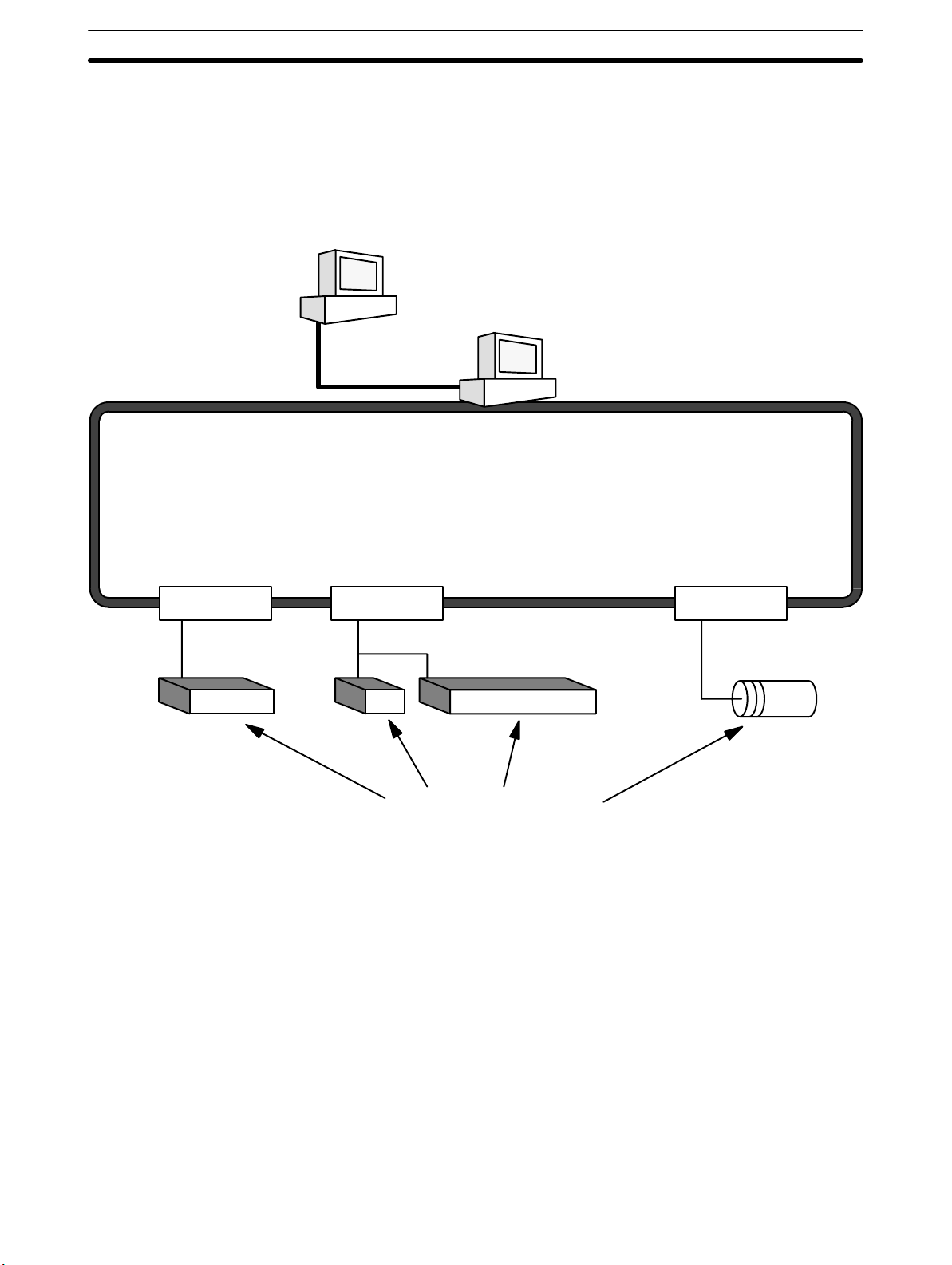
1-1 What is a Control System?
A Control System is the electronic equipment needed to control a particular process. It may include everything from a process control computer, if one is used,
to the factory computer, down through the PCs (and there may be many of them
networked together) and then on down through the network to the control components: the switches, stepping motors, solenoids, and sensors which monitor
and control the mechanical operations.
Process Control Computer
Factory Computer
PCs
PC PC PC
Control Components
A Control System can involve very large applications where many different models of PC are networked together or it could be an application as small as a single
PC controlling a single output device.
2
What is a Control System? Section 1-1
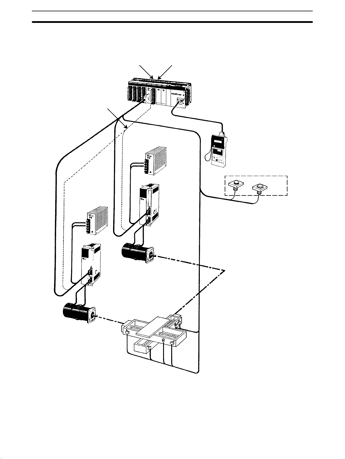
A Position Control System
Position Control Unit
Signal line for
Servomotor
driver control
Power
source
Input Unit
Power
source
DC Servomotor
Driver
PC
Hand-held Programming
Console
Control panel
Control switch
DC Servomotor Driver
DC Servomotor
In the typical Control System example shown above, a PC controls the movement of the workpiece bed across two horizontal axes using Limit Switches and
Servomotors to monitor and control movement.
DC Servomotor
3
The Role of the PC Section 1-2
1-2 The Role of the PC
The Programmable Controller, or PC, is the part of the Control System that
directly controls the manufacturing process. According to the program stored in
its memory, the PC accepts data from the input devices connected to it, and uses
this data to monitor the controlled system. When the program calls for some
action to take place, the PC sends data to the output devices connected to it, to
cause that action to take place. The PC may be used to control a simple, repetitive task, or it may be connected to other PCs, or to a host computer in order to
integrate the control of a complex process.
1-2-1 Input Devices
PCs can receive input from either automated or manual devices. The PC could
receive data from the user via a pushbutton switch, keyboard, or similar device.
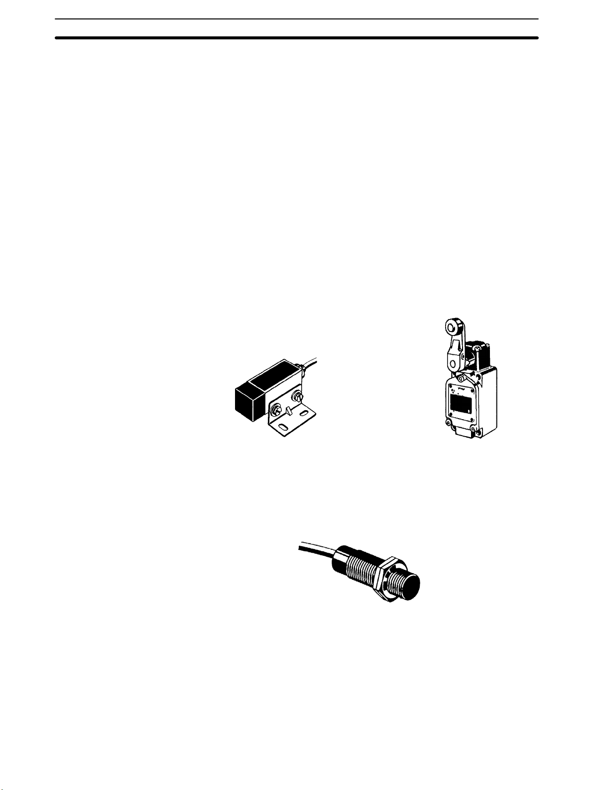
Automated input could come from a variety of devices: microswitches, timers,
encoders, photosensors, and so on. Some devices, like the Limit Switch shown
below, turn ON or OFF when the equipment actually makes contact with it. Other
devices, like the Photoelectric Switch and Proximity Switch shown below, use
other means, such as light or inductance, in order to get information about the
equipment being monitored.
1-2-2 Output Devices
Photoelectric switch Limit switch
Proximity switch
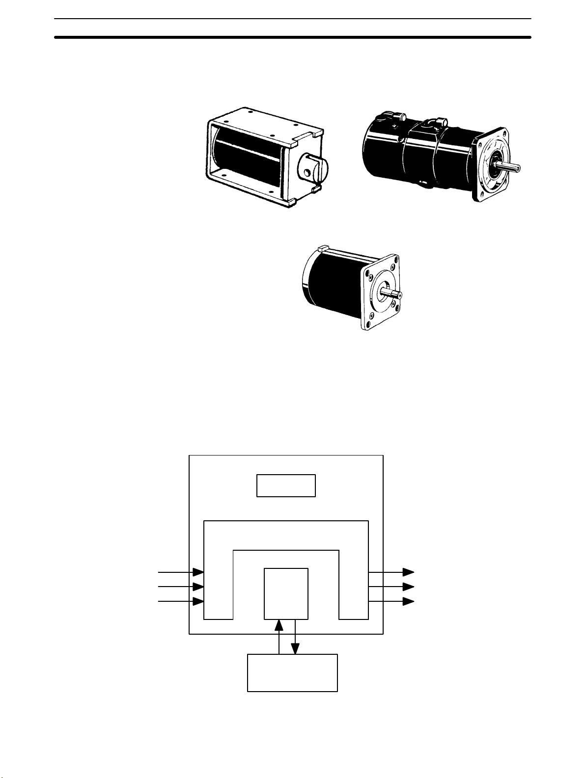
A PC can output to a myriad of devices for use in automated control. Almost anything that you can think of could be controlled (perhaps indirectly) by a PC. Some
of the most common devices are motors, Solenoids, Servomotors, Stepping
Motors, valves, switches, indicator lights, buzzers, and alarms. Some of these
output devices; such as the motors, Solenoids, Servomotors, Stepping Motors,
4
How Does a PC Work? Section 1-3
and valves; affect the controlled system directly. Others; such as the indicator
lights, buzzers, and alarms; provide output to notify personnel.
Solenoid
1-3 How Does a PC Work?
PCs operate by monitoring input signals and providing output signals. When
changes are detected in the signals, the PC reacts, through the user-programmed internal logic, to produce output signals. The PC continually scans the
program in its memory to achieve this control.
Block Diagram of PC
Servomotor
Stepping motor
Power Supply
Signals
from
switches,
sensors,
etc.
Memory
Signals to
Input Output
CPU
Programming
Device
Solenoids,
motors,
etc.
A program for your applications must be designed, and stored in the PC. This
program is then executed as part of the cycle of internal operations of the PC.
5

How Does a PC Work? Section 1-3
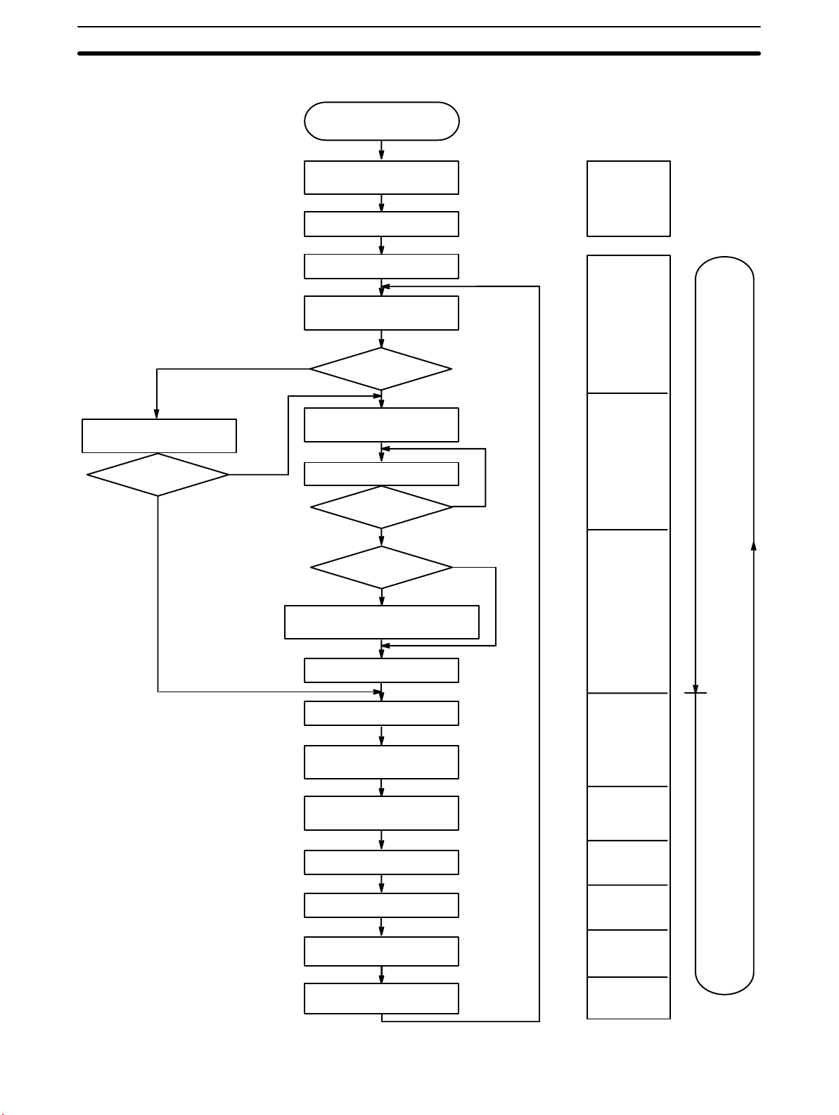
Cycle When a PC operates, that is, when it executes its program to control an external
system, a series of operations are performed inside the PC. These internal
operations can be broadly classified into the following four categories:
1, 2, 3... 1. Common (or overseeing) processes, such as watchdog timer operation and
testing the program memory.
2. Data input and output.
3. Instruction execution.
4. Peripheral device servicing.
Cycle Time The total time required for a PC to perform all these internal operations is called
the cycle time. The flowchart and diagram on the following page illustrate these
internal operations for a typical PC.
Timing is one of the most important factors in designing a Control System. For
accurate operations, it is necessary to have answers to such questions as these:
• How long does it take for the PC to execute all the instructions in its memory?
• How long does it take for the PC to produce a control output in response to a
given input signal?
The cycle time of the PC can be automatically calculated and monitored, but it is
necessary to have an understanding of the timing relationships within the PC for
effective system design and programming.
6
How Does a PC Work? Section 1-3
Flowchart of CPU Operation
Sets error flags and turns
ON or flashes indicator
ALARM/ERROR
ERROR
(Solid ON)
ALARM
(Flashing)
Power application
Clears IR area and
resets all timers
Checks I/O Unit connections
Resets watchdog timer
Checks hardware and
Program Memory
NO
Check OK?
Resets watchdog timer and
program address counter
Executes program
End of program?
Initialization on
power-up
Overseeing
processes
YES
Program
execution
NO
YES
SCAN(18)
executed?
NO
YES
Resets watchdog timer and waits
until the set cycle time has elapsed
Calculates cycle time
Resets watchdog timer
Refreshes input bits
and output signals
Services RS-232C
connector
Services Host Link Units
Services Peripheral devices
Services Communications
Boards
Services SYSMAC LINK and
SYSMAC NET Link Units
Cycle time
calculation
I/O refreshing
RS-232C
connector
servicing
Host Link Unit
servicing
Peripheral
device
servicing
Communicatio
ns Board
servicing
SYSMAC LINK
and SYSMAC
NET servicing
PC
cycle
time
7


SECTION 2
System Configuration and Units
This section describes the system configuration used for the C200HX/C200HG/C200HE PCs and the individual Units used in
the system configuration.
2-1 Basic Configuration 10. . . . . . . . . . . . . . . . . . . . . . . . . . . . . . . . . . . . . . . . . . . . . . . . . . . . . . .
2-1-1 CPU Rack 10. . . . . . . . . . . . . . . . . . . . . . . . . . . . . . . . . . . . . . . . . . . . . . . . . . . . . . .
2-1-2 Expansion I/O Racks 13. . . . . . . . . . . . . . . . . . . . . . . . . . . . . . . . . . . . . . . . . . . . . . .
2-1-3 I/O Connecting Cable 14. . . . . . . . . . . . . . . . . . . . . . . . . . . . . . . . . . . . . . . . . . . . . .
2-2 Units 14. . . . . . . . . . . . . . . . . . . . . . . . . . . . . . . . . . . . . . . . . . . . . . . . . . . . . . . . . . . . . . . . . . .
2-2-1 CPU Units 14. . . . . . . . . . . . . . . . . . . . . . . . . . . . . . . . . . . . . . . . . . . . . . . . . . . . . . .
2-2-2 Memory Cassettes 17. . . . . . . . . . . . . . . . . . . . . . . . . . . . . . . . . . . . . . . . . . . . . . . . .
2-2-3 Communications Boards 18. . . . . . . . . . . . . . . . . . . . . . . . . . . . . . . . . . . . . . . . . . . .
2-2-4 Power Supply Units 19. . . . . . . . . . . . . . . . . . . . . . . . . . . . . . . . . . . . . . . . . . . . . . . .
2-2-5 Backplanes 24. . . . . . . . . . . . . . . . . . . . . . . . . . . . . . . . . . . . . . . . . . . . . . . . . . . . . . .
2-2-6 Standard I/O Units 25. . . . . . . . . . . . . . . . . . . . . . . . . . . . . . . . . . . . . . . . . . . . . . . . .
2-2-7 Group-2 High-density I/O Units 27. . . . . . . . . . . . . . . . . . . . . . . . . . . . . . . . . . . . . .
2-2-8 High-density I/O Units Classified as Special I/O Units 30. . . . . . . . . . . . . . . . . . . .
2-3 Peripheral Devices 31. . . . . . . . . . . . . . . . . . . . . . . . . . . . . . . . . . . . . . . . . . . . . . . . . . . . . . . .
2-3-1 Programming Consoles 31. . . . . . . . . . . . . . . . . . . . . . . . . . . . . . . . . . . . . . . . . . . . .
2-3-2 Ladder Support Software (LSS) 31. . . . . . . . . . . . . . . . . . . . . . . . . . . . . . . . . . . . . .
2-3-3 SYSMAC Support Software (SSS) 32. . . . . . . . . . . . . . . . . . . . . . . . . . . . . . . . . . . .
2-3-4 SYSMAC-CPT Support Software 32. . . . . . . . . . . . . . . . . . . . . . . . . . . . . . . . . . . . .
2-4 Expanded System Configurations 33. . . . . . . . . . . . . . . . . . . . . . . . . . . . . . . . . . . . . . . . . . . .
2-4-1 Required Mounting Conditions 33. . . . . . . . . . . . . . . . . . . . . . . . . . . . . . . . . . . . . . .
2-4-2 Special I/O Units 33. . . . . . . . . . . . . . . . . . . . . . . . . . . . . . . . . . . . . . . . . . . . . . . . . .
2-4-3 Link Systems and Networks 40. . . . . . . . . . . . . . . . . . . . . . . . . . . . . . . . . . . . . . . . .
9
Basic Configuration Section 2-1
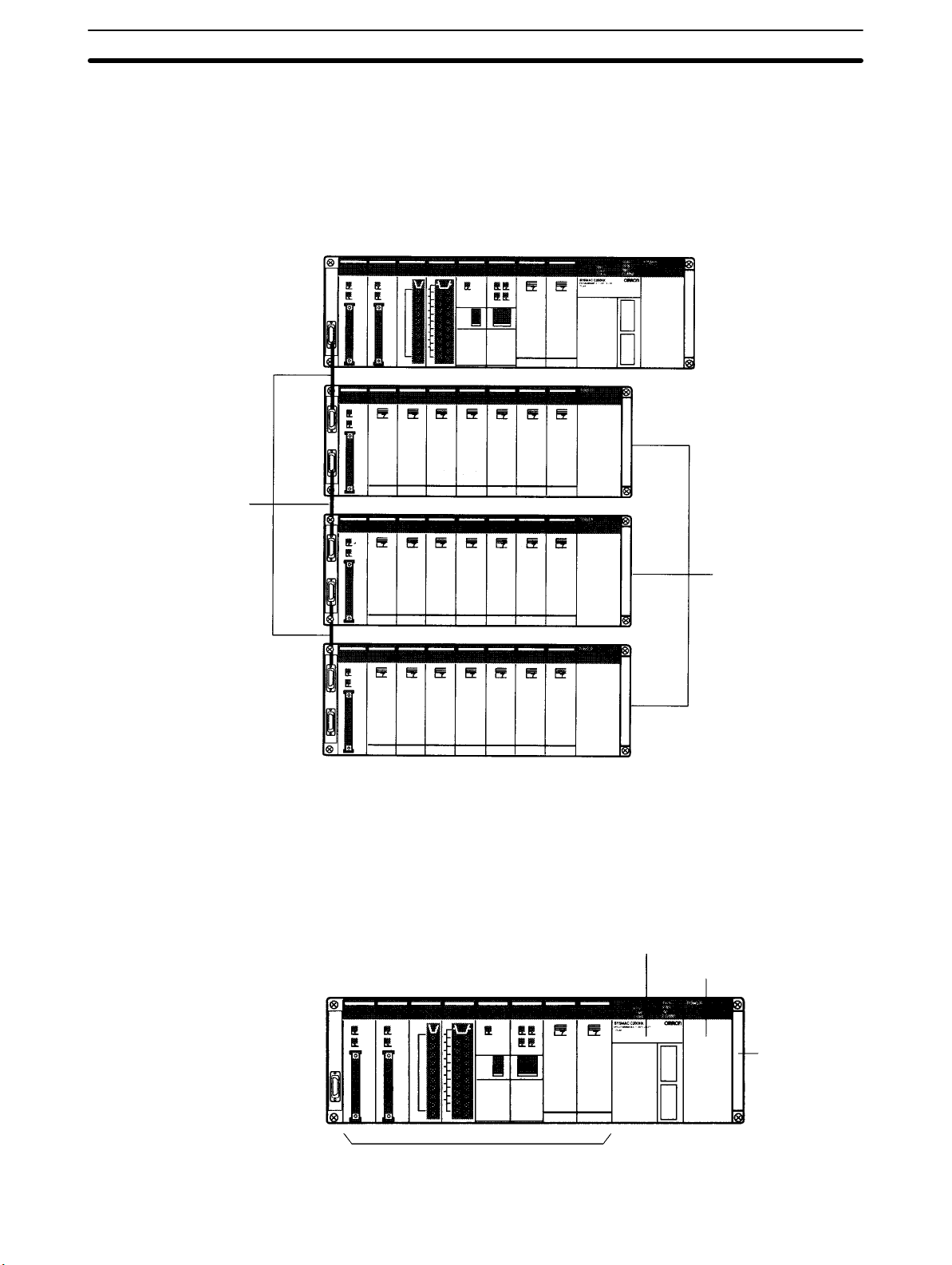
2-1 Basic Configuration
The basic configuration of the PC is shown below. With the C200HX/
C200HG/C200HE, up to two or up to three Expansion I/O Racks (depending on
the CPU Unit) can be connected to the CPU Rack, depending on the number of
I/O points required in the system.
CPU Rack
I/O Connecting Cables
2-1-1 CPU Rack
Expansion I/O Racks
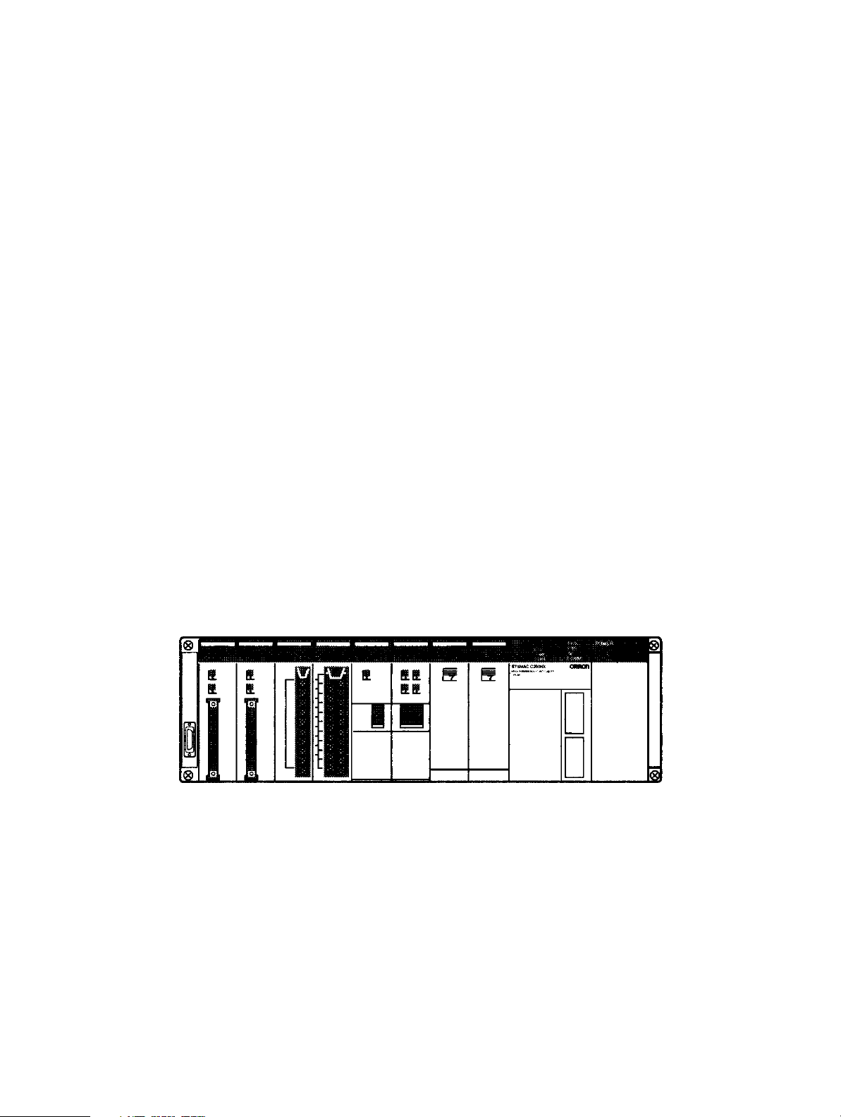
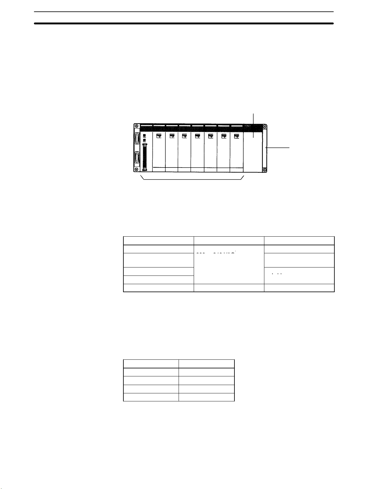
An example of a CPU Rack is shown below. The CPU Rack consists of a CPU
Backplane, CPU Unit, Power Supply Unit, I/O Units, and other special Units.
CPU Unit
Power Supply Unit
10
CPU Backplane
Other Units

,
Basic Configuration Section 2-1
Power Supply Units The Power Supply Unit supplies power to the CPU Rack. The Power Supply
Units listed in the following table are available. Refer to 2-2-4 Power Supply
Units for further details.
Model Supply voltage Remarks
C200HW-PA204
C200HW-PA204S
C200HW-PA204R/PA209R
(See note.)
C200HW-PD024 24 VDC ---
Note The C200HW-PA204R/PA209R cannot be used with all combinations of CPU
Units and Backplanes. Refer to page 23, Restrictions for the C200HW-PA204R/
PA209R, for details.
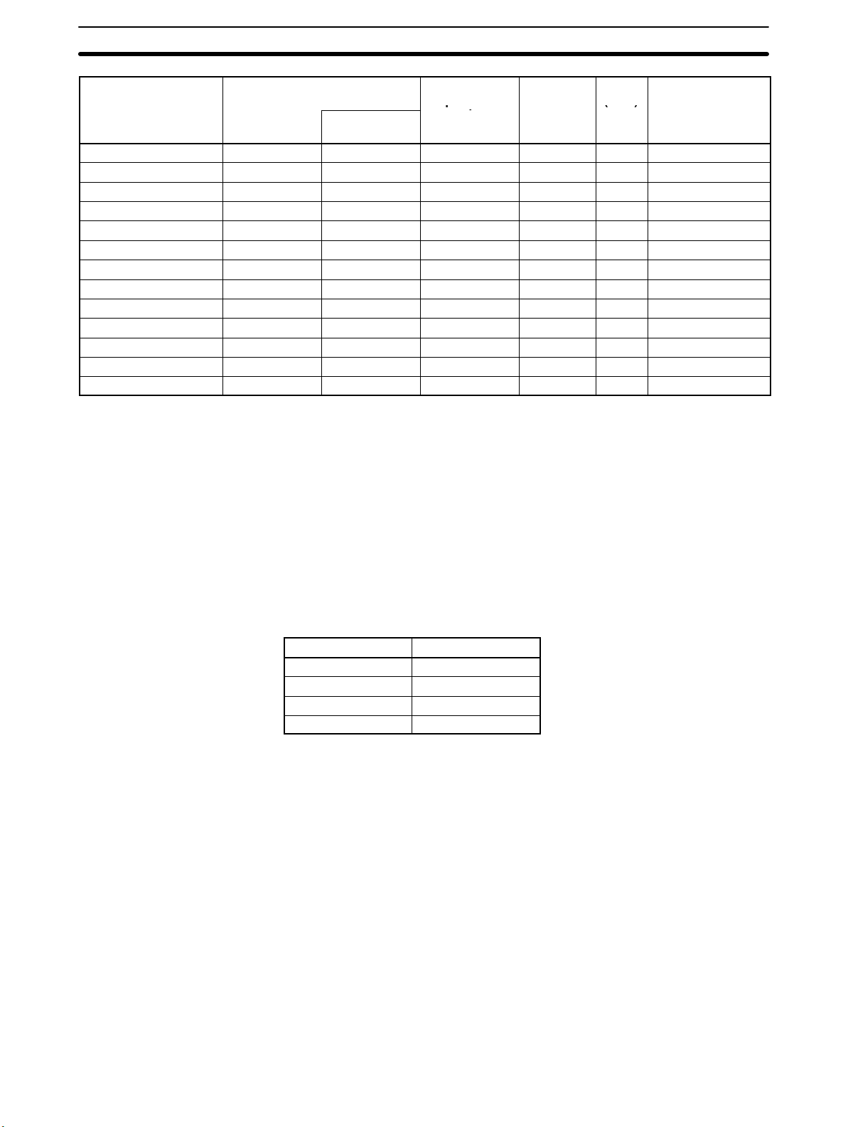
CPU Units The CPU Units listed in the following tables are available. Refer to 2-2-1 CPU
Units for further details on the CPU Units.
100 to 120 VAC,
200 to 240 VAC
---
Provides 24-VDC output
terminals.
Equipped with RUN output
contacts.
Model User
program
memory
C200HE-CPU11-E/ZE 3.2K words 4K words --- 0.3 µs min. 640 points 2 Racks
C200HE-CPU32-E/ZE 7.2K words 6K words --- 0.3 µs min. 880 points 2 Racks
C200HE-CPU42-E/ZE 7.2K words 6K words --- 0.3 µs min. 880 points 2 Racks
C200HG-CPU33-E/ZE 15.2K words 6K words 6K words 0.15 µs min. 880 points 2 Racks
C200HG-CPU43-E/ZE 15.2K words 6K words 6K words 0.15 µs min. 880 points 2 Racks
C200HG-CPU53-E/ZE 15.2K words 6K words 6K words 0.15 µs min. 1,184 points 3 Racks
C200HG-CPU63-E/ZE 15.2K words 6K words 6K words 0.15 µs min. 1,184 points 3 Racks
C200HX-CPU34-E/ZE 31.2K words 6K words 6K words x 3
C200HX-CPU44-E/ZE 31.2K words 6K words 6K words x 3
C200HX-CPU54-E/ZE 31.2K words 6K words 6K words x 3
C200HX-CPU64-E/ZE 31.2K words 6K words 6K words x 3
C200HX-CPU65-ZE 63.2K words 6K words 6K words x 8
C200HX-CPU85-ZE 63.2K words 6K words 6K words x 16
Data
memory
Extended
data memory
(EM)
(18K words)
(18K words)
(18K words)
(18K words)
(48K words)
(96K words)
Instruction
processing
time (basic
instructions)
0.1 µs min. 880 points 2 Racks
0.1 µs min. 880 points 2 Racks
0.1 µs min. 1,184 points 3 Racks
0.1 µs min. 1,184 points 3 Racks
0.1 µs min. 1,184 points 3 Racks
0.1 µs min. 1,184 points 3 Racks
Max. real I/O
points
supported
Max. No. of
Expansion
I/O Racks
11
Spec a /O
(C)
oa d
Basic Configuration Section 2-1
Model
C200HE-CPU11-E/ZE Not supported Not supported 10 Units No No No
C200HE-CPU32-E/ZE 10 Units 5 Units 10 Units No Yes Ye s
C200HE-CPU42-E/ZE 10 Units 5 Units 10 Units Yes Yes Yes
C200HG-CPU33-E/ZE 10 Units 5 Units 10 Units No Ye s Yes
C200HG-CPU43-E/ZE 10 Units 5 Units 10 Units Ye s Yes Ye s
C200HG-CPU53-E/ZE 16 Units 8 Units 16 Units No Ye s Yes
C200HG-CPU63-E/ZE 16 Units 8 Units 16 Units Ye s Yes Ye s
C200HX-CPU34-E/ZE 10 Units 5 Units 10 Units No Yes Ye s
C200HX-CPU44-E/ZE 10 Units 5 Units 10 Units Yes Yes Yes
C200HX-CPU54-E/ZE 16 Units 8 Units 16 Units No Yes Ye s
C200HX-CPU64-E/ZE 16 Units 8 Units 16 Units Yes Yes Yes
C200HX-CPU65-ZE 16 Units 8 Units 16 Units Ye s Yes Ye s
C200HX-CPU85-ZE 16 Units 8 Units 16 Units Ye s Yes Ye s
Max. No. of Group-2
High-density I/O Units
64-point Units
(see note 1)
Max. No. of
Special I/O
Units
(see note 2)
RS-232C Clock
(RTC)
Communications
Note 1. Each 64 I/O Unit is treated as two Units.
2. Special I/O Units like the C200H-NC211 that are allocated the words for two
Units are treated as two Units.
3. Unit number settings for Group-2 Units for the following CPU Units must be
between 0 and 9:
C200HE-CPU32/42-E/ZE
C200HG-CPU33/43-E/ZE
C200HX-CPU34/44-E/ZE
Board
CPU Backplane The CPU Backplane is required to mount the CPU Unit and other Units compos-
ing the CPU Rack. The following CPU Backplanes are available depending on
the number of slot required for Units. Refer to 2-2-5 Backplanes for further
details.
Model Number of slots
C200HW-BC031 3
C200HW-BC051 5
C200HW-BC081-V1 8
C200HW-BC101-V1 10
Note When using the C200HW-PA209R Power Supply Unit with an 8-slot or 10-slot
CPU Backplane or Expansion I/O Backplane, be sure to use the C200HWBC081-V1 or C200HW-BC101-V1.
Other Units The other Units that can be mounted to the CPU Rack include the Standard I/O
Units, High-density I/O Units, and Special I/O Units.
12
,
qpp
Basic Configuration Section 2-1
2-1-2 Expansion I/O Racks
An example of an Expansion I/O Rack is shown in the following diagram. Expansion I/O Racks consist of and I/O Backplane, Power Supply Unit, I/O Units, and
other Units. Expansion I/O Racks are connected to the CPU Rack to increase
the number of I/O Units and other Units that can be used by the PC. You can
connect up to 2 or up to 3 Expansion I/O Racks to a CPU Rack, the number
depending on the CPU Unit that is used.
Power Supply Unit
I/O Backplane
Other Units
Power Supply Unit The Power Supply Unit supplies power to the Expansion I/O Rack. The Power
Supply Units listed in the following table are available. Refer to 2-2-4 Power Sup-
ply Units for further details.
Model Supply voltage Remarks
C200HW-PA204
C200HW-PA204S
C200HW-PD204R
C200HW-PD209R
C200HW-PD024 24 VDC
100 to 120 VAC,
200 to 240 VAC
---
Provides 24-VDC output
terminals.
Equipped with RUN
output contacts.
Note RUN output contacts cannot be used with Expansion I/O Racks.
I/O Backplane The I/O Backplane is required to mount the Power Supply Unit and other Units
composing the Expansion I/O Rack. The following I/O Backplanes are available
depending on the number of slot required for Units. Refer to 2-2-5 Backplanes
for further details.
Model Number of slots
C200HW-BI031 3
C200HW-BI051 5
C200HW-BI081-V1 8
C200HW-BI101-V1 10
Note When using the C200HW-PA209R Power Supply Unit with an 8 or 10-slot Back-
plane, be sure to use the C200HW-BC081-V1 or C200HW-BC101-V1.
Other Units The other Units that can be mounted to an Expansion I/O Rack include the Stan-
dard I/O Units, High-density I/O Units, and Special I/O Units.
13
Units
2-1-3 I/O Connecting Cable
The first Expansion I/O Rack is connected to the CPU Rack, and the second and
third Expansion I/O Racks are connected to the previous Expansion I/O Rack
through I/O Connecting Cable. There are five different lengths of cable available, which can be used as desired to provide the desired distance between
each Rack. The sum of the lengths of all the I/O Connecting Cables connected
within one PC, however, but be 12 m or less.
Model Cable length
C200H-CN311 30 cm
C200H-CN711 70 cm
C200H-CN221 2 m
C200H-CN521 5 m
C200H-CN131 10 m
Section 2-2
2-2 Units
2-2-1 CPU Units
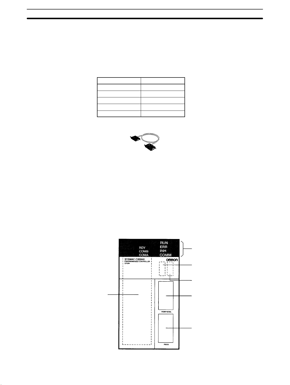
6. Communications Board
compartment
The following diagram shows the components of the CPU Unit as viewed from
the front cover. The numbers in the diagram correspond to the numbers of the
following items in the description.
1. Indicators
2. Memory Casette
compartment
3. DIP Switch
4. Peripheral port
14
5. RS-232C port

Units
Section 2-2
1, 2, 3... 1. Indicators
The indicators (LEDs) on the front cover of the CPU Unit operate as
described in the following table.
LED Contents
RUN (green) Lights when the PC is operating normally in MONITOR
or RUN mode.
ERR (red) Flashes if an error occurs that does not stop the CPU
Unit (a non-fatal error).
Lights if an error occurs that stops the CPU Unit (a fatal
error). If a fatal error occurs, the RUN indicator will turn
OFF and the outputs from all Output Units will turn OFF.
INH (orange) Lights when the Load OFF Bit (SR 25215) turns ON. If
the Load OFF Bit is turned ON, the outputs from all
Output Units will turn OFF.
COMM (orange) Lights when the CPU Unit is communicating via the
peripheral or RS-232C port.
2. Memory Casette Compartment
The Memory Cassette compartment contains the built-in RAM and can be
used to mount an optional Memory Cassette. Refer to 3-1-8 Mounting
Memory Cassettes for the mounting methods.
15

Units
3. DIP Switch
The DIP switch is used to make various settings that determine who the PC
will operate. The C200HX/C200HG/C200HE CPU Unit has a 6-pin DIP
switch, as shown in the following diagram. The settings of these pins are
listed in the following table.
Pin no. Setting Function
1
ON Writing disabled for user memory.
OFF Writing enabled for user memory.
2
ON Contents of the Memory Cassette automatically read when power is turned on.
OFF Contents of the Memory Cassette not automatically read when power is turned on.
3
ON Programming Console messages displayed in English.
OFF Programming Console messages displayed in the language stored in system ROM. (Messages
displayed in Japanese with the Japanese version of system ROM.)
4
ON Setting function for special instructions enabled.
OFF Setting function for special instructions disabled (default).
5
ON Standard communications parameters (see note) will be set for the following serial communications
ports.
• Built-in RS-232C port
• Peripheral port (only when a CQM1-CIF01/-CIF02 Cable is connected. Does not apply to Program-
ming Console.)
Note 1. Standard communications parameters are as follows:
Serial communications mode: Host Link or peripheral bus; start bits: 1; data length: 7 bits;
parity: even; stop bits: 2; baud rate: 9,600 bps
2. The CX-Programmer running on a personal computer can be connected to the peripheral
port via the peripheral bus using the above standard communications parameters.
OFF The communications parameters for the following serial communications ports will be set in PC
Setup as follows:
• Built-in RS-232C port: DM 6645 and DM 6646
• Peripheral port: DM 6650 and DM 6651
Note When the CX-Programmer is connected to the peripheral port with the peripheral bus, either set
bits 00 to 03 of DM 6650 to 0 Hex (for standard parameters), or set bits 12 to 15 of DM 6650 to 0
Hex and bits 00 to 03 of DM 6650 to 1 Hex (for Host Link or peripheral bus) separately.
6
ON Expansion TERMINAL mode for the Programming Console; AR 0712: ON
OFF Console mode for the Programming Console; AR 0712: OFF
Section 2-2
16
Note All pins are set to OFF for the factory defaults.
4. Peripheral Port
The peripheral port is connected to peripheral devices, such as the Programming Console.
5. RS-232C Port
The RS-232C port is connected to external devices that support an
RS-232C interface, such as personal computers.
6. Communications Board Compartment
The Communications Board compartment is used to mount a Communica-

Units
Section 2-2
tions Board. Refer to 3-1-9 Mounting a Communications Board for the
mounting methods.
2-2-2 Memory Cassettes
Memory Cassettes can be optionally mounted to increase memory capacity
over just the built-in RAM. There are two types of Memory Cassette available.
These are shown in the following diagram.
EEPROM Memory Cassette EPROM Memory Cassette
Notch
C200HW-ME
EEPROM Memory Cassette When an EEPROM Memory Cassette is installed in the CPU Unit, the user
memory (UM) and I/O data can be directly read and written. There is no need for
a backup power supply. The Memory Cassette can also be removed from the
CPU Unit and used for storing data.
Model Capacity
C200HW-ME04K 4K words
C200HW-ME08K 8K words
C200HW-ME16K 16K words
C200HW-ME32K 32K words
C200HW-ME64K 64K words
Note The C200HW-ME64K can be used with the C200HX-CPU65-ZE/CPU85-ZE
CPU Units only. It cannot be used with other CPU Units.
EPROM Memory Cassette With an EPROM Memory Cassette, the program is written using a PROM Writer.
The ROM is mounted to the Memory Casette and then installed in the CPU Unit.
I/O data cannot be stored.
Model Capacity
C200HS-MP16K 16K words/32K words
Memory Cassette Settings
EEPROM Memory Cassette Set the DIP switch. For an EEPROM Memory Cassette, set pin no. 1 (write pro-
tect) to either ON or OFF. Setting it to ON will protect the program in the memory
from being overwritten. Setting it to OFF will allow the program to be overwritten.
(The factory setting is OFF.)
EPROM Memory Cassette For an EPROM Memory Cassette, set pin no. 1 (ROM Type Selector) according
to the type of ROM that is mounted.
Pin no. 1 ROM type Model Capacity Access speed
OFF 27256 ROM-JD-B 16K words 150 ns
ON 27512 ROM-KD-B 32K words 150 ns
17
Units
2-2-3 Communications Boards
An optional Communications Board can be mounted in the CPU Unit to provide
communications with the following types of devices/systems through the communications port: SYSMAC LINK Systems, SYSMAC NET Systems, personal
computers, Programmable Terminals (PTs), bar code readers, temperature
controllers, devices with RS-232C or RS-422 interfaces, etc.
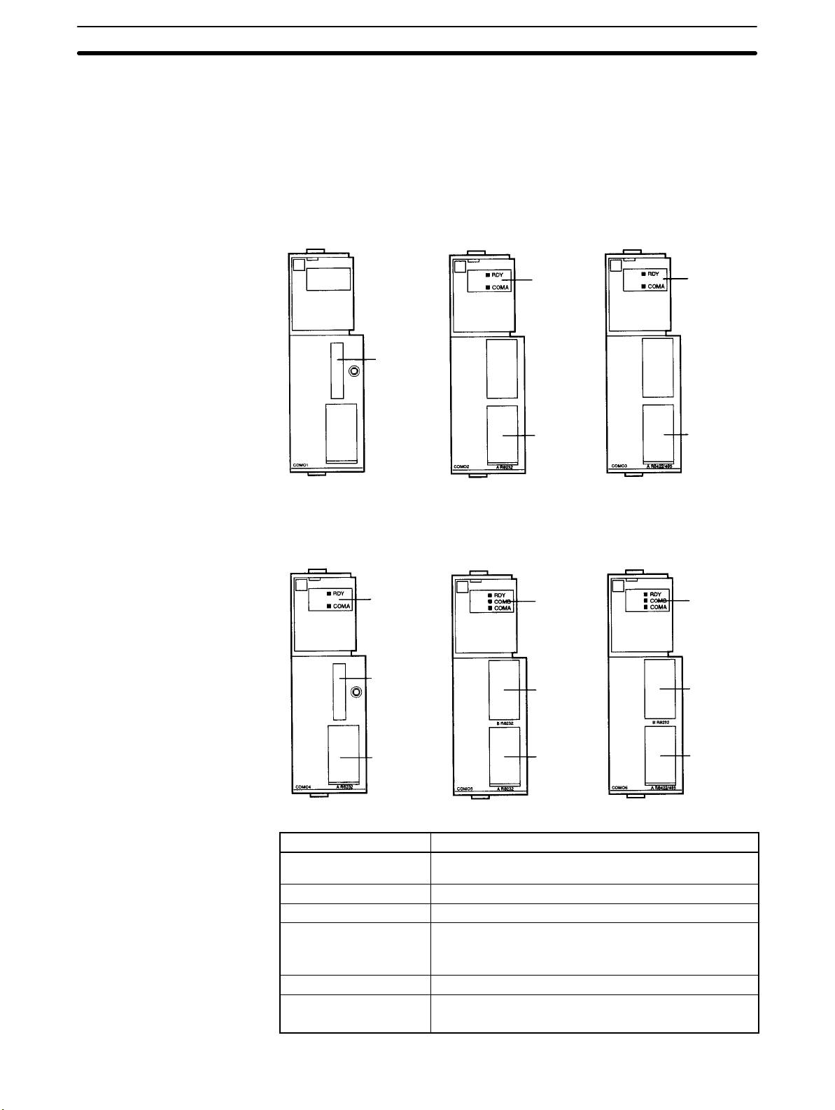
The following Communications Boards are available.
C200HW-COM01 C200HW-COM02-V1 C200HW-COM03-V1
Section 2-2
Indicators Indicators
Bus
Connecting
Unit
connector
Port A
(RS-232C)
Port A
(RS-422/
RS-485)
C200HW-COM04-EV1 C200HW-COM05-EV1 C200HW-COM06-EV1
Indicators
Bus
Connecting
Unit
connector
Port A
(RS-232C)
Indicators Indicators
Port B
(RS-232C)
Port A
(RS-232C)
Port B
(RS-232C)
Port A
(RS-422/
RS-485)
18
Model
Specifications
C200HW-COM01 Connection port for SYSMAC LINK, SYSMAC NET, or
other Communications Units.
C200HW-COM02-V1 RS-232C port x 1
C200HW-COM03-V1 RS-422/485 port x 1
C200HW-COM04-EV1 Connection port for SYSMAC LINK, SYSMAC NET, or
other Communications Units.
RS-232C port x 1 (supports protocol macros)
C200HW-COM05-EV1 RS-232C port x 2 (supports protocol macros)
C200HW-COM06-EV1 RS-422/485 port x 1 (supports protocol macros)
RS-232C port x 1 (supports protocol macros)
 Loading...