

Omron C1000H-SLK11, C200HW-SLK14, C1000H-SLK21-V1, C200HW-SLK23, C200HW-SLK24 System Manual
...
Cat. No. W174-E1-07
SYSMAC
C-Series
SYSMAC LINK
SYSTEM MANUAL

C-series SYSMAC LINK
System Manual
Revised September 2003
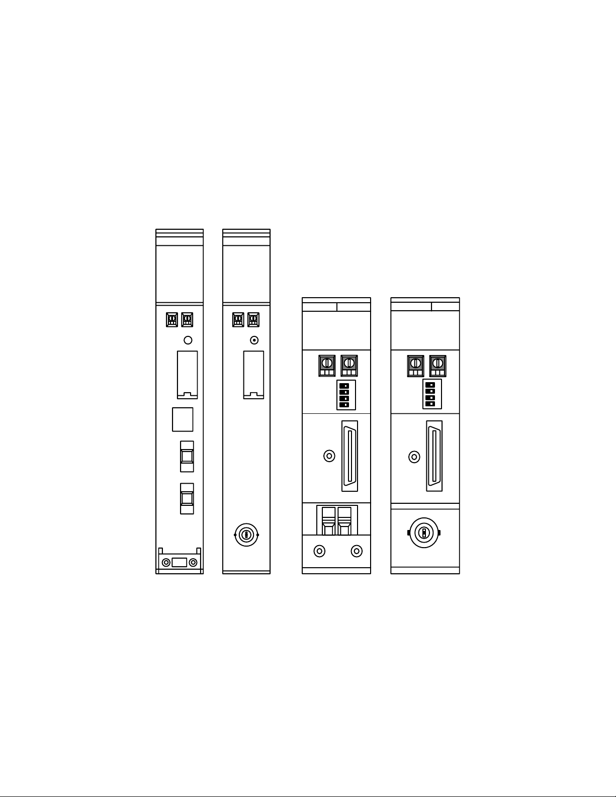
SLK11
RUN
ERC
INS
SD
TS
P/S
ERH
M/S
RD
LNK
SLK21-V1
RUN
ERC
INS
SD
TS
ERH
M/S
RD
LNK
SLK14
RUN
ERC
INS
SD
P/S
ERH
M/S
RD
TS
LNK
SLK24
RUN
ERC
INS
SD
ERH
M/S
RD
TS
LNK

Terms and Conditions of Sale
1. Offer; Acceptance. These terms and conditions (these "Terms") are deemed
part of all quotes, agreements, purchase orders, acknowledgments, price lists,
catalogs, manuals, brochures and other documents, whether electronic or in
writing, relating to the sale of products or services (collectively, the "Products
by Omron Electronics LLC and its subsidiary companies (“Omron”). Omron
objects to any terms or conditions proposed in Buyer’s purchase order or other
documents which are inconsistent with, or in addition to, these Terms.
2. Prices; Payment Terms.
out notice by Omron. Omron reserves the right to increase or decrease prices
on any unshipped portions of outstanding orders. Payments for Products are
due net 30 days unless otherwise stated in the invoice.
3. Discounts.
sent to Buyer after deducting transportation charges, taxes and duties, and will
be allowed only if (i) the invoice is paid according to Omron’s payment terms
and (ii) Buyer has no past due amounts.
4. Interest.
the maximum legal rate, whichever is less, on any balance not paid within the
stated terms.
5. Orders
6. Governmental Approvals.
costs involved in, obtaining any government approvals required for the importation or sale of the Products.
7. Taxes
real property and income taxes), including any interest or penalties thereon,
imposed directly or indirectly on Omron or required to be collected directly or
indirectly by Omron for the manufacture, production, sale, delivery, importation, consumption or use of the Products sold hereunder (including customs
duties and sales, excise, use, turnover and license taxes) shall be charged to
and remitted by Buyer to Omron.
8. Financial.
to Omron, Omron reserves the right to stop shipments or require satisfactory
security or payment in advance. If Buyer fails to make payment or otherwise
comply with these Terms or any related agreement, Omron may (without liability and in addition to other remedies) cancel any unshipped portion of Products sold hereunder and stop any Products in transit until Buyer pays all
amounts, including amounts payable hereunder, whether or not then due,
which are owing to it by Buyer. Buyer shall in any event remain liable for all
unpaid accounts.
9. Cancellation; Etc.
unless Buyer indemnifies Omron against all related costs or expenses.
10. Force Majeure
resulting from causes beyond its control, including earthquakes, fires, floods,
strikes or other labor disputes, shortage of labor or materials, accidents to
machinery, acts of sabotage, riots, delay in or lack of transportation or the
requirements of any government authority.
11. Shipping; Delivery.
a. Shipments shall be by a carrier selected by Omron; Omron will not drop ship
b. Such carrier shall act as the agent of Buyer and delivery to such carrier shall
c. All sales and shipments of Products shall be FOB shipping point (unless oth-
d. Delivery and shipping dates are estimates only; and
e. Omron will package Products as it deems proper for protection against nor-
12. Claims.
Products occurring before delivery to the carrier must be presented in writing
to Omron within 30 days of receipt of shipment and include the original transportation bill signed by the carrier noting that the carrier received the Products
from Omron in the condition claimed.
13. Warranties
Products will be free from defects in materials and workmanship for a period of
twelve months from the date of sale by Omron (or such other period expressed
in writing by Omron). Omron disclaims all other warranties, express or implied.
(b) Limitations
EXPRESS OR IMPLIED, ABOUT NON-INFRINGEMENT, MERCHANTABIL-
Cash discounts, if any, will apply only on the net amount of invoices
Omron, at its option, may charge Buyer 1-1/2% interest per month or
. Omron will accept no order less than $200 net billing.
. All taxes, duties and other governmental charges (other than general
If the financial position of Buyer at any time becomes unsatisfactory
except in “break down” situations.
constitute delivery to Buyer;
erwise stated in writing by Omron), at which point title and risk of loss shall
pass from Omron to Buyer; provided that Omron shall retain a security interest in the Products until the full purchase price is paid;
mal handling and extra charges apply to special conditions.
Any claim by Buyer against Omron for shortage or damage to the
. (a) Exclusive Warranty. Omron’s exclusive warranty is that the
All prices stated are current, subject to change with-
Buyer shall be responsible for, and shall bear all
Orders are not subject to rescheduling or cancellation
. Omron shall not be liable for any delay or failure in delivery
Unless otherwise expressly agreed in writing by Omron:
. OMRON MAKES NO WARRANTY OR REPRESENTATION,
ITY OR FITNESS FOR A PARTICULAR PURPOSE OF THE PRODUCTS.
BUYER ACKNOWLEDGES THAT IT ALONE HAS DETERMINED THAT THE
PRODUCTS WILL SUITABLY MEET THE REQUIREMENTS OF THEIR
")
INTENDED USE. Omron further disclaims all warranties and responsibility of
any type for claims or expenses based on infringement by the Products or otherwise of any intellectual property right. (c) Buyer Remedy
gation hereunder shall be, at Omron’s election, to (i) replace (in the form
originally shipped with Buyer responsible for labor charges for removal or
replacement thereof) the non-complying Product, (ii) repair the non-complying
Product, or (iii) repay or credit Buyer an amount equal to the purchase price of
the non-complying Product; provided that in no event shall Omron be responsible for warranty, repair, indemnity or any other claims or expenses regarding
the Products unless Omron’s analysis confirms that the Products were properly handled, stored, installed and maintained and not subject to contamination, abuse, misuse or inappropriate modification. Return of any Products by
Buyer must be approved in writing by Omron before shipment. Omron Companies shall not be liable for the suitability or unsuitability or the results from the
use of Products in combination with any electrical or electronic components,
circuits, system assemblies or any other materials or substances or environments. Any advice, recommendations or information given orally or in writing,
are not to be construed as an amendment or addition to the above warranty.
See http://oeweb.omron.com or contact your Omron representative for published information.
14. Limitation on Liability; Etc
FOR SPECIAL, INDIRECT, INCIDENTAL, OR CONSEQUENTIAL DAMAGES,
LOSS OF PROFITS OR PRODUCTION OR COMMERCIAL LOSS IN ANY
WAY CONNECTED WITH THE PRODUCTS, WHETHER SUCH CLAIM IS
BASED IN CONTRACT, WARRANTY, NEGLIGENCE OR STRICT LIABILITY.
Further, in no event shall liability of Omron Companies exceed the individual
price of the Product on which liability is asserted.
15. Indemnities
their employees from and against all liabilities, losses, claims, costs and
expenses (including attorney's fees and expenses) related to any claim, investigation, litigation or proceeding (whether or not Omron is a party) which arises
or is alleged to arise from Buyer's acts or omissions under these Terms or in
any way with respect to the Products. Without limiting the foregoing, Buyer (at
its own expense) shall indemnify and hold harmless Omron and defend or settle any action brought against such Companies to the extent based on a claim
that any Product made to Buyer specifications infringed intellectual property
rights of another party.
16. Property; Confidentiality.
sive property of Omron Companies and Buyer shall not attempt to duplicate it
in any way without the written permission of Omron. Notwithstanding any
charges to Buyer for engineering or tooling, all engineering and tooling shall
remain the exclusive property of Omron. All information and materials supplied
by Omron to Buyer relating to the Products are confidential and proprietary,
and Buyer shall limit distribution thereof to its trusted employees and strictly
prevent disclosure to any third party.
17. Export Controls.
licenses regarding (i) export of products or information; (iii) sale of products to
“forbidden” or other proscribed persons; and (ii) disclosure to non-citizens of
regulated technology or information.
18. Miscellaneous
and no course of dealing between Buyer and Omron shall operate as a waiver
of rights by Omron. (b) Assignment
without Omron's written consent. (c) Law.
law of the jurisdiction of the home office of the Omron company from which
Buyer is purchasing the Products (without regard to conflict of law principles). (d) Amendment
Buyer and Omron relating to the Products, and no provision may be changed
or waived unless in writing signed by the parties. (e) Severability
sion hereof is rendered ineffective or invalid, such provision shall not invalidate
any other provision. (f) Setoff
against the amount owing in respect of this invoice. (g) Definitions
herein, “including” means “including without limitation”; and “Omron Companies” (or similar words) mean Omron Corporation and any direct or indirect
subsidiary or affiliate thereof.
. Buyer shall indemnify and hold harmless Omron Companies and
Buyer shall comply with all applicable laws, regulations and
. (a) Waiver. No failure or delay by Omron in exercising any right
. OMRON COMPANIES SHALL NOT BE LIABLE
Any intellectual property in the Products is the exclu-
. Buyer may not assign its rights hereunder
These Terms are governed by the
. These Terms constitute the entire agreement between
. Buyer shall have no right to set off any amounts
. Omron’s sole obli-
. If any provi-
. As used
Certain Precautions on Specifications and Use
1. Suitability of Use. Omron Companies shall not be responsible for conformity
with any standards, codes or regulations which apply to the combination of the
Product in the Buyer’s application or use of the Product. At Buyer’s request,
Omron will provide applicable third party certification documents identifying
ratings and limitations of use which apply to the Product. This information by
itself is not sufficient for a complete determination of the suitability of the Product in combination with the end product, machine, system, or other application
or use. Buyer shall be solely responsible for determining appropriateness of
the particular Product with respect to Buyer’s application, product or system.
Buyer shall take application responsibility in all cases but the following is a
non-exhaustive list of applications for which particular attention must be given:
(i) Outdoor use, uses involving potential chemical contamination or electrical
interference, or conditions or uses not described in this document.
(ii) Use in consumer products or any use in significant quantities.
(iii) Energy control systems, combustion systems, railroad systems, aviation
systems, medical equipment, amusement machines, vehicles, safety equipment, and installations subject to separate industry or government regulations.
(iv) Systems, machines and equipment that could present a risk to life or property. Please know and observe all prohibitions of use applicable to this Product.
NEVER USE THE PRODUCT FOR AN APPLICATION INVOLVING SERIOUS
RISK TO LIFE OR PROPERTY OR IN LARGE QUANTITIES WITHOUT
ENSURING THAT THE SYSTEM AS A WHOLE HAS BEEN DESIGNED TO
iv
ADDRESS THE RISKS, AND THAT THE OMRON’S PRODUCT IS PROPERLY RATED AND INSTALLED FOR THE INTENDED USE WITHIN THE
OVERALL EQUIPMENT OR SYSTEM.
2. Programmable Products.
user’s programming of a programmable Product, or any consequence thereof.
3. Performance Data
and other materials is provided as a guide for the user in determining suitability and does not constitute a warranty. It may represent the result of Omron’s
test conditions, and the user must correlate it to actual application requirements. Actual performance is subject to the Omron’s Warranty and Limitations
of Liability.
4. Change in Specifications
changed at any time based on improvements and other reasons. It is our practice to change part numbers when published ratings or features are changed,
or when significant construction changes are made. However, some specifications of the Product may be changed without any notice. When in doubt, special part numbers may be assigned to fix or establish key specifications for
your application. Please consult with your Omron’s representative at any time
to confirm actual specifications of purchased Product.
5. Errors and Omissions.
checked and is believed to be accurate; however, no responsibility is assumed
for clerical, typographical or proofreading errors or omissions.
Omron Companies shall not be responsible for the
. Data presented in Omron Company websites, catalogs
. Product specifications and accessories may be
Information presented by Omron Companies has been

Notice:
OMRON products are manufactured for use according to proper procedures by a qualified operator
and only for the purposes described in this manual.
The following conventions are used to indicate and classify precautions in this manual. Always heed
the information provided with them. Failure to heed precautions can result in injury to people or damage to the product.
DANGER Indicates an imminently hazardous situation which, if not avoided, will result in death or
!
serious injury.
WARNING Indicates a potentially hazardous situation which, if not avoided, could result in death or
!
serious injury.
Caution Indicates a potentially hazardous situation which, if not avoided, may result in minor or
!
moderate injury, or property damage.
OMRON Product References
All OMRON products are capitalized in this manual. The word “Unit” is also capitalized when it refers
to an OMRON product, regardless of whether or not it appears in the proper name of the product.
The abbreviation “Ch,” which appears in some displays and on some OMRON products, often means
“word” and is abbreviated “Wd” in documentation in this sense.
The abbreviation “PC” means Programmable Controller and is not used as an abbreviation for anything else.
Visual Aids
The following headings appear in the left column of the manual to help you locate different types of
information.
© OMRON, 1990
All rights reserved. No part of this publication may be reproduced, stored in a retrieval system, or transmitted, in any
form, or by any means, mechanical, electronic, photocopying, recording, or otherwise, without the prior written permission of OMRON.
No patent liability is assumed with respect to the use of the information contained herein. Moreover, because OMRON is
constantly striving to improve its high-quality products, the information contained in this manual is subject to change
without notice. Every precaution has been taken in the preparation of this manual. Nevertheless, OMRON assumes no
responsibility for errors or omissions. Neither is any liability assumed for damages resulting from the use of the information contained in this publication.
Note Indicates information of particular interest for efficient and convenient operation
of the product.
1, 2, 3...
1. Indicates lists of one sort or another, such as procedures, checklists, etc.
v

vi

TABLE OF CONTENTS
PRECAUTIONS xi. . . . . . . . . . . . . . . . . . . . . . . . . . . . . . . . .
1 Intended Audience xii. . . . . . . . . . . . . . . . . . . . . . . . . . . . . . . . . . . . . . . . . . . . . . . . . . . . . . . . . . .
2 General Precautions xii. . . . . . . . . . . . . . . . . . . . . . . . . . . . . . . . . . . . . . . . . . . . . . . . . . . . . . . . . .
3 Safety Precautions xii. . . . . . . . . . . . . . . . . . . . . . . . . . . . . . . . . . . . . . . . . . . . . . . . . . . . . . . . . . .
4 Operating Environment Precautions xiii. . . . . . . . . . . . . . . . . . . . . . . . . . . . . . . . . . . . . . . . . . . . .
5 Application Precautions xiii. . . . . . . . . . . . . . . . . . . . . . . . . . . . . . . . . . . . . . . . . . . . . . . . . . . . . .
SECTION 1
Introduction 1. . . . . . . . . . . . . . . . . . . . . . . . . . . . . . . . . . . .
1-1 OMRON Network Systems 2. . . . . . . . . . . . . . . . . . . . . . . . . . . . . . . . . . . . . . . . . . . . . . . .
1-2 SYSMAC LINK System Features 3. . . . . . . . . . . . . . . . . . . . . . . . . . . . . . . . . . . . . . . . . . .
1-3 System Configuration 4. . . . . . . . . . . . . . . . . . . . . . . . . . . . . . . . . . . . . . . . . . . . . . . . . . . . .
1-4 Unit Compatibility 6. . . . . . . . . . . . . . . . . . . . . . . . . . . . . . . . . . . . . . . . . . . . . . . . . . . . . . .
1-5 Precautions 8. . . . . . . . . . . . . . . . . . . . . . . . . . . . . . . . . . . . . . . . . . . . . . . . . . . . . . . . . . . . .
SECTION 2
Unit Components and Switch Settings 9. . . . . . . . . . . . . . .
2-1 C1000H-SLK11/SLK21-V1 Components 10. . . . . . . . . . . . . . . . . . . . . . . . . . . . . . . . . . . . .
2-2 C200HW-SLK13/14/23/24 Components 12. . . . . . . . . . . . . . . . . . . . . . . . . . . . . . . . . . . . . .
2-3 Indicators 13. . . . . . . . . . . . . . . . . . . . . . . . . . . . . . . . . . . . . . . . . . . . . . . . . . . . . . . . . . . . . .
2-4 Switches 14. . . . . . . . . . . . . . . . . . . . . . . . . . . . . . . . . . . . . . . . . . . . . . . . . . . . . . . . . . . . . . .
2-5 Setting Switches 15. . . . . . . . . . . . . . . . . . . . . . . . . . . . . . . . . . . . . . . . . . . . . . . . . . . . . . . . .
SECTION 3
Installation 17. . . . . . . . . . . . . . . . . . . . . . . . . . . . . . . . . . . . .
3-1 Mounting Position 18. . . . . . . . . . . . . . . . . . . . . . . . . . . . . . . . . . . . . . . . . . . . . . . . . . . . . . .
3-2 Power Supply Unit Connection 20. . . . . . . . . . . . . . . . . . . . . . . . . . . . . . . . . . . . . . . . . . . . .
3-3 Bus Connector (C200HX/HG/HE/HS/H only) 25. . . . . . . . . . . . . . . . . . . . . . . . . . . . . . . . .
3-4 Cable Connection 26. . . . . . . . . . . . . . . . . . . . . . . . . . . . . . . . . . . . . . . . . . . . . . . . . . . . . . . .
3-5 Dimensions 33. . . . . . . . . . . . . . . . . . . . . . . . . . . . . . . . . . . . . . . . . . . . . . . . . . . . . . . . . . . . .
SECTION 4
Basic Communications 35. . . . . . . . . . . . . . . . . . . . . . . . . . .
4-1 SYSMAC LINK System Communications 36. . . . . . . . . . . . . . . . . . . . . . . . . . . . . . . . . . . .
4-2 Setting Node Numbers 37. . . . . . . . . . . . . . . . . . . . . . . . . . . . . . . . . . . . . . . . . . . . . . . . . . . .
4-3 Operating Levels 38. . . . . . . . . . . . . . . . . . . . . . . . . . . . . . . . . . . . . . . . . . . . . . . . . . . . . . . .
4-4 PC Mode at Start-up (C1000H only) 38. . . . . . . . . . . . . . . . . . . . . . . . . . . . . . . . . . . . . . . . .
4-5 Polling Unit Setting 39. . . . . . . . . . . . . . . . . . . . . . . . . . . . . . . . . . . . . . . . . . . . . . . . . . . . . .
4-6 Setting Network Parameters 40. . . . . . . . . . . . . . . . . . . . . . . . . . . . . . . . . . . . . . . . . . . . . . . .
4-7 Network Parameter Initialization 41. . . . . . . . . . . . . . . . . . . . . . . . . . . . . . . . . . . . . . . . . . . .
4-8 Active Node Flags 42. . . . . . . . . . . . . . . . . . . . . . . . . . . . . . . . . . . . . . . . . . . . . . . . . . . . . . .
SECTION 5
Data Links 43. . . . . . . . . . . . . . . . . . . . . . . . . . . . . . . . . . . . .
5-1 Data Link Overview 44. . . . . . . . . . . . . . . . . . . . . . . . . . . . . . . . . . . . . . . . . . . . . . . . . . . . . .
5-2 Creating Data Links 45. . . . . . . . . . . . . . . . . . . . . . . . . . . . . . . . . . . . . . . . . . . . . . . . . . . . . .
5-3 Automatic Generation of Data Link Tables 46. . . . . . . . . . . . . . . . . . . . . . . . . . . . . . . . . . . .
5-4 Manual Generation of Data Link Tables 48. . . . . . . . . . . . . . . . . . . . . . . . . . . . . . . . . . . . . .
5-5 Data Link Table Examples 51. . . . . . . . . . . . . . . . . . . . . . . . . . . . . . . . . . . . . . . . . . . . . . . . .
5-6 Restrictions on C200HW-SLK13/14/23/24 Data Link Areas 55. . . . . . . . . . . . . . . . . . . . . .
5-7 Controlling Data Links 58. . . . . . . . . . . . . . . . . . . . . . . . . . . . . . . . . . . . . . . . . . . . . . . . . . . .
5-8 Data Link Precautions 59. . . . . . . . . . . . . . . . . . . . . . . . . . . . . . . . . . . . . . . . . . . . . . . . . . . .
5-9 Data Link Status 60. . . . . . . . . . . . . . . . . . . . . . . . . . . . . . . . . . . . . . . . . . . . . . . . . . . . . . . . .
5-10 Data Link Characteristics 63. . . . . . . . . . . . . . . . . . . . . . . . . . . . . . . . . . . . . . . . . . . . . . . . . .
vii

TABLE OF CONTENTS
SECTION 6
Data Read/Write Services 73. . . . . . . . . . . . . . . . . . . . . . . . .
6-1 About Data Read/Write Services 74. . . . . . . . . . . . . . . . . . . . . . . . . . . . . . . . . . . . . . . . . . . .
6-2 NETWORK READ/WRITE Instructions 74. . . . . . . . . . . . . . . . . . . . . . . . . . . . . . . . . . . . .
6-3 CV-mode Command/Response Format 86. . . . . . . . . . . . . . . . . . . . . . . . . . . . . . . . . . . . . . .
6-4 Memory Area Designations 88. . . . . . . . . . . . . . . . . . . . . . . . . . . . . . . . . . . . . . . . . . . . . . . .
6-5 CV-mode Commands for PCs 90. . . . . . . . . . . . . . . . . . . . . . . . . . . . . . . . . . . . . . . . . . . . . .
6-6 CV-mode Commands for SYSMAC LINK Units 103. . . . . . . . . . . . . . . . . . . . . . . . . . . . . . .
SECTION 7
Special Services 111. . . . . . . . . . . . . . . . . . . . . . . . . . . . . . . . .
7-1 Remote Programming and Monitoring 112. . . . . . . . . . . . . . . . . . . . . . . . . . . . . . . . . . . . . . .
7-2 RAS Functions 113. . . . . . . . . . . . . . . . . . . . . . . . . . . . . . . . . . . . . . . . . . . . . . . . . . . . . . . . . .
SECTION 8
Error Processing 117. . . . . . . . . . . . . . . . . . . . . . . . . . . . . . . .
8-1 Troubleshooting 118. . . . . . . . . . . . . . . . . . . . . . . . . . . . . . . . . . . . . . . . . . . . . . . . . . . . . . . . .
8-2 Network Troubleshooting 124. . . . . . . . . . . . . . . . . . . . . . . . . . . . . . . . . . . . . . . . . . . . . . . . . .
SECTION 9
Inspection and Maintenance 129. . . . . . . . . . . . . . . . . . . . . . .
9-1 Periodic Inspection 130. . . . . . . . . . . . . . . . . . . . . . . . . . . . . . . . . . . . . . . . . . . . . . . . . . . . . . .
9-2 Replacing SYSMAC LINK Units 131. . . . . . . . . . . . . . . . . . . . . . . . . . . . . . . . . . . . . . . . . . .
Appendices
A Standard Models 133. . . . . . . . . . . . . . . . . . . . . . . . . . . . . . . . . . . . . . . . . . . . . . . . . . . . . . . . . . .
B Specifications 137. . . . . . . . . . . . . . . . . . . . . . . . . . . . . . . . . . . . . . . . . . . . . . . . . . . . . . . . . . . . . .
C Internal Configuration 139. . . . . . . . . . . . . . . . . . . . . . . . . . . . . . . . . . . . . . . . . . . . . . . . . . . . . . .
Glossary 141. . . . . . . . . . . . . . . . . . . . . . . . . . . . . . . . . . . . . . .
Index 153. . . . . . . . . . . . . . . . . . . . . . . . . . . . . . . . . . . . . . . . . .
Revision History 157. . . . . . . . . . . . . . . . . . . . . . . . . . . . . . . . .
viii

About this Manual:
This manual describes the installation and operation of C-series SYSMAC LINK Units and includes the
sections described below.
Please read this manual completely and be sure you understand the information provide before attempting to install and operate a C-series SYSMAC LINK System.
Section 5 Introduction
describes the possible system configurations and compatibility with PCs and other Link Units.
Section 6 Unit Components and Switch Settings
LINK Units’ components and the switch settings.
Section 7 Installation
Section 8 Basic Communications
MAC LINK Systems and explains the basic settings necessary for operation.
Section 9 Data Links
and methods of monitoring data link operations.
Section 10 Data Read/Write Services
mission between nodes and distributed control. The data read/write services include the NETWORK
READ (RECV(98)) and NETWORK WRITE (SEND(90)) and instructions and CV-mode commands.
Section 11 Special Services
functions.
Section 12 Error Processing
the System.
Section 13 Inspection and Maintenance
how to replace a SYSMAC LINK Unit.
introduces the features and operations possible with SYSMAC LINK Units. It also
presents the names and functions of the SYSMAC
explains how to install SYSMAC LINK Systems.
introduces the token bus method of communications used in SYS-
describes the operation of data links, procedures required to establish data links,
describes the data read/write services, which provide data trans-
provides information on remote programming and monitoring and RAS
provides information to help identify and correct errors that might occur in
describes periodic maintenance required by the System and
!
WARNING Failure to read and understand the information provided in this manual may result in
personal injury or death, damage to the product, or product failure. Please read each
section in its entirety and be sure you understand the information provided in the section
and related sections before attempting any of the procedures or operations given.
ix


PRECAUTIONS
This section provides general precautions for using the Programmable Controller and related devices.
The information contained in this section is important for the safe and reliable application of the PC. You must read
this section and understand the information contained before attempting to set up or operate a PC system.
1 Intended Audience xii. . . . . . . . . . . . . . . . . . . . . . . . . . . . . . . . . . . . . . . . . . . . . . . . . . . . . . . . . . . .
2 General Precautions xii. . . . . . . . . . . . . . . . . . . . . . . . . . . . . . . . . . . . . . . . . . . . . . . . . . . . . . . . . . .
3 Safety Precautions xii. . . . . . . . . . . . . . . . . . . . . . . . . . . . . . . . . . . . . . . . . . . . . . . . . . . . . . . . . . . .
4 Operating Environment Precautions xiii. . . . . . . . . . . . . . . . . . . . . . . . . . . . . . . . . . . . . . . . . . . . . .
5 Application Precautions xiii. . . . . . . . . . . . . . . . . . . . . . . . . . . . . . . . . . . . . . . . . . . . . . . . . . . . . . . .
xi

1 Intended Audience
This manual is intended for the following personnel, who must also have knowledge of electrical systems (an electrical engineer or the equivalent).
• Personnel in charge of installing FA systems.
• Personnel in charge of designing FA systems.
• Personnel in charge of managing FA systems and facilities.
2 General Precautions
The user must operate the product according to the performance specifications
described in the relevant manuals.
Before using the product under conditions which are not described in the manual
or applying the product to nuclear control systems, railroad systems, aviation
systems, vehicles, combustion systems, medical equipment, amusement machines, safety equipment, and other systems, machines, and equipment that
may have a serious influence on lives and property if used improperly, consult
your OMRON representative.
Make sure that the ratings and performance characteristics of the product are
sufficient for the systems, machines, and equipment, and be sure to provide the
systems, machines, and equipment with double safety mechanisms.
This manual provides information for programming and operating the Unit. Be
sure to read this manual before attempting to use the Unit and keep this manual
close at hand for reference during operation.
5Safety Precautions
WARNING It is extremely important that a PC and all PC Units be used for the specified
!
purpose and under the specified conditions, especially in applications that can
directly or indirectly affect human life. You must consult with your OMRON
representative before applying a PC system to the above-mentioned
applications.
3 Safety Precautions
WARNING Do not attempt to take any Unit apart while the power is being supplied. Doing so
!
may result in electric shock.
WARNING Do not touch any of the terminals or terminal blocks while the power is being
!
supplied. Doing so may result in electric shock.
WARNING Do not attempt to disassemble, repair, or modify any Units. Any attempt to do so
!
may result in malfunction, fire, or electric shock.
xii

4 Operating Environment Precautions
Caution Do not operate the control system in the following locations:
!
• Locations subject to direct sunlight.
• Locations subject to temperatures or humidity outside the range specified in
the specifications.
• Locations subject to condensation as the result of severe changes in temperature.
• Locations subject to corrosive or flammable gases.
• Locations subject to dust (especially iron dust) or salts.
• Locations subject to exposure to water, oil, or chemicals.
• Locations subject to shock or vibration.
Caution Take appropriate and sufficient countermeasures when installing systems in the
!
following locations:
• Locations subject to static electricity or other forms of noise.
• Locations subject to strong electromagnetic fields.
• Locations subject to possible exposure to radioactivity.
• Locations close to power supplies.
5Application Precautions
Caution The operating environment of the PC system can have a large effect on the lon-
!
gevity and reliability of the system. Improper operating environments can lead to
malfunction, failure, and other unforeseeable problems with the PC system. Be
sure that the operating environment is within the specified conditions at installation and remains within the specified conditions during the life of the system.
5 Application Precautions
Observe the following precautions when using the PC system.
WARNING Always heed these precautions. Failure to abide by the following precautions
!
could lead to serious or possibly fatal injury.
• Always ground the system to 100 Ω or less when installing the Units. Not connecting to a ground of 100 Ω or less may result in electric shock.
• Always turn OFF the power supply to the PC before attempting any of the following. Not turning OFF the power supply may result in malfunction or electric
shock.
• Mounting or dismounting Power Supply Units, I/O Units, CPU Units,
Memory Units, or any other Units.
• Assembling the Units.
• Setting DIP switches or rotary switches.
• Connecting cables or wiring the system.
• Connecting or disconnecting the connectors.
Caution Failure to abide by the following precautions could lead to faulty operation of the
!
PC or the system, or could damage the PC or PC Units. Always heed these precautions.
• Fail-safe measures must be taken by the customer to ensure safety in the
event of incorrect, missing, or abnormal signals caused by broken signal lines,
momentary power interruptions, or other causes.
xiii

5Application Precautions
• Always use the power supply voltages specified in this manual. An incorrect
voltage may result in malfunction or burning.
• Take appropriate measures to ensure that the specified power with the rated
voltage and frequency is supplied. Be particularly careful in places where the
power supply is unstable. An incorrect power supply may result in malfunction.
• Install external breakers and take other safety measures against short-circuiting in external wiring. Insufficient safety measures against short-circuiting may
result in burning.
• Do not apply voltages to the Input Units in excess of the rated input voltage.
Excess voltages may result in burning.
• Do not apply voltages or connect loads to the Output Units in excess of the
maximum switching capacity. Excess voltage or loads may result in burning.
• Disconnect the functional ground terminal when performing withstand voltage
tests. Not disconnecting the functional ground terminal may result in burning.
• Be sure that all the mounting screws, terminal screws, and cable connector
screws are tightened to the torque specified in this manual. Incorrect tightening torque may result in malfunction.
• Leave the label attached to the Unit when wiring. Removing the label may result in malfunction if foreign matter enters the Unit.
• Remove the label after the completion of wiring to ensure proper heat dissipation. Leaving the label attached may result in malfunction.
• Double-check all wiring and switch settings before turning ON the power supply. Incorrect wiring may result in burning.
• Wire correctly. Incorrect wiring may result in burning.
• Mount Units only after checking terminal blocks and connectors completely.
• Be sure that the terminal blocks, Memory Units, expansion cables, and other
items with locking devices are properly locked into place. Improper locking
may result in malfunction.
• Check the user program for proper execution before actually running it on the
Unit. Not checking the program may result in an unexpected operation.
• Confirm that no adverse effect will occur in the system before attempting any of
the following. Not doing so may result in an unexpected operation.
• Changing the operating mode of the PC.
• Force-setting/force-resetting any bit in memory.
• Changing the present value of any word or any set value in memory.
• Resume operation only after transferring to the new CPU Unit the contents of
the DM Area, HR Area, and other data required for resuming operation. Not
doing so may result in an unexpected operation.
• Do not pull on the cables or bend the cables beyond their natural limit. Doing
either of these may break the cables.
• Do not place objects on top of the cables or other wiring lines. Doing so may
break the cables.
• Use crimp terminals for wiring. Do not connect bare stranded wires directly to
terminals. Connection of bare stranded wires may result in burning.
• When replacing parts, be sure to confirm that the rating of a new part is correct.
Not doing so may result in malfunction or burning.
• Before touching a Unit, be sure to first touch a grounded metallic object in order
to discharge any static built-up. Not doing so may result in malfunction or damage.
xiv

SECTION 1
Introduction
This section introduces the features and operations of the SYSMAC LINK Units. It also describes the possible system configurations and compatibility with PCs and other Link Units.
1-1 OMRON Network Systems 2. . . . . . . . . . . . . . . . . . . . . . . . . . . . . . . . . . . . . . . . . . . . . . . . .
1-2 SYSMAC LINK System Features 3. . . . . . . . . . . . . . . . . . . . . . . . . . . . . . . . . . . . . . . . . . . .
1-3 System Configuration 4. . . . . . . . . . . . . . . . . . . . . . . . . . . . . . . . . . . . . . . . . . . . . . . . . . . . . .
1-3-1 Single-level Systems 4. . . . . . . . . . . . . . . . . . . . . . . . . . . . . . . . . . . . . . . . . . . . . . .
1-3-2 Multilevel System 5. . . . . . . . . . . . . . . . . . . . . . . . . . . . . . . . . . . . . . . . . . . . . . . . .
1-4 Unit Compatibility 6. . . . . . . . . . . . . . . . . . . . . . . . . . . . . . . . . . . . . . . . . . . . . . . . . . . . . . . .
1-4-1 Compatibility with PCs 6. . . . . . . . . . . . . . . . . . . . . . . . . . . . . . . . . . . . . . . . . . . . .
1-4-2 Compatibility with Other Link Units 6. . . . . . . . . . . . . . . . . . . . . . . . . . . . . . . . . . .
1-5 Precautions 8. . . . . . . . . . . . . . . . . . . . . . . . . . . . . . . . . . . . . . . . . . . . . . . . . . . . . . . . . . . . . .
1
OMRON Network Systems Section 1-1
1-1 OMRON Network Systems
As production processes become more complex and diversified, it is necessary to develop networks that link control components such as PCs to more
powerful host computers in LANs that control entire production processes.
OMRON provides 3 types of network systems for large, medium, and smallscale networks.
SYSMAC NET Link System The SYSMAC NET Link System is a high-speed, high-capacity LAN. It can be
used as a gateway to a general LAN composed of different kinds of computers or
to an Ethernet to create a large-scale network.
SYSMAC LINK System The SYSMAC LINK System provides high-speed, high-capacity communica-
tions between any nodes (PCs, or IBM-PC/AT or compatible running SSS) in the
network, as well as remote monitoring and programming functions and automatic data transfer via data links.
SYSMAC BUS System The SYSMAC BUS Remote I/O System is used to link a single PC to remote
racks called Slave Racks and/or components (e.g., I/O Terminals or Programmable Terminals) to form a small, decentralized control network.
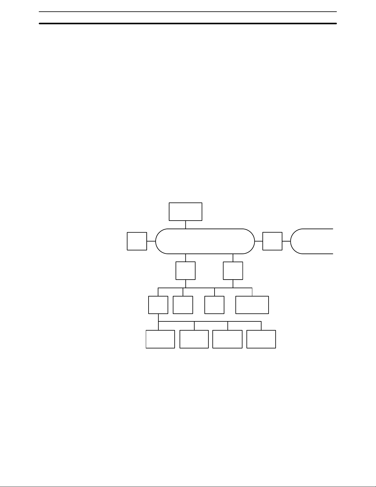
Depending on the size and complexity of the production process, these systems can be used alone or in combination as shown below.
PC
Host
computer
SYSMAC NET Link System
PC
PCPC
SYSMAC BUS Remote I/O System
Expansion
I/O Rack
Expansion
I/O Rack
PC
I/O Terminal
PC
Bridge
SYSMAC LINK System
Host
computer
Expansion
I/O Rack
SYSMAC NET
Link System
2

SYSMAC LINK System Features Section 1-2
1-2 SYSMAC LINK System Features
SYSMAC LINK Units are equipped with a variety of special features.
High Speed, Reliability, and
Flexibility
Distributed Control with
Data Links
The specialized communications LSIs used in all SYSMAC LINK Units deliver
high speed, reliability, and flexibility in an advanced data link system, while optical fiber cable systems provide high-speed communications with unparalleled
immunity to noise.
In the event of an error or failure in the polling unit, another node automatically takes over management of the SYSMAC LINK System without stopping
the entire network. SSS or CVSS running on an IBM-PC/AT or compatible
can monitor and/or program PCs anywhere in the network via the SYSMAC
LINK System.
The data link function transfers data to and from other nodes automatically,
establishing simple but powerful peer-to-peer links between nodes. Data links
can be generated automatically between 2, 4, 8, or 16 nodes by changing the
value of just one byte in the AR Area of the start-up node. Or the user can use the
flexibility of manually generating data links to eliminate unused link words,
improve data link I/O response time, and to even create several data link groups
in one network.
The data link communications cycle time can be fixed at a constant value, so
even simultaneous remote programming/monitoring and NETWORK READ/
WRITE instruction (RECV(98)/SEND(90)) execution have no effect on the
data link I/O response time.
Active PC Transmission PCs can communicate actively with other PCs in the network. The four functions
listed below can be performed from the PC’s program using the SEND(90) and
RECV(98) instructions (SEND(192), RECV(193), and CMND(194) in the CVseries).
1, 2, 3...
RAS Functions SYSMAC LINK Units are equipped with three RAS functions (RAS is an acro-
Improvements on the
C200HS-SLK12/SLK22
(C200HW-SLK13/SLK14/
SLK23/SLK24)
1. Broadcast transmission
2. Response monitoring time setting (response time-out setting)
3. Transmit retry setting
4. Enabling/disabling response
nym for reliability, availability, and serviceability). The Polling Unit Backup and
Failed Node Bypass (optical systems only) functions prevent the network from
failing when one Unit fails. The Internode Echo Test function aids in communications troubleshooting.
Remote monitoring of the network’s operating status also aids in troubleshooting and quick correction of communications problems.
Up to 2,966 words can be linked using the data link function with the C200HWSLK14/SLK24.
The input interrupt response time is 1 ms maximum when the new SYSMAC
LINK Units are mounted to a C200HX, C200HG, or C200HE PC.
3
System Configuration Section 1-3
1-3 System Configuration
Up to 62 nodes (including all PCs and, in coaxial systems, computers) can be
connected in a SYSMAC LINK Network via SYSMAC LINK Units or Network
Service Boards. One of the Units in the network will function as the polling
unit and the remainder will be polled units. The polling unit manages the System communications during and after configuration.
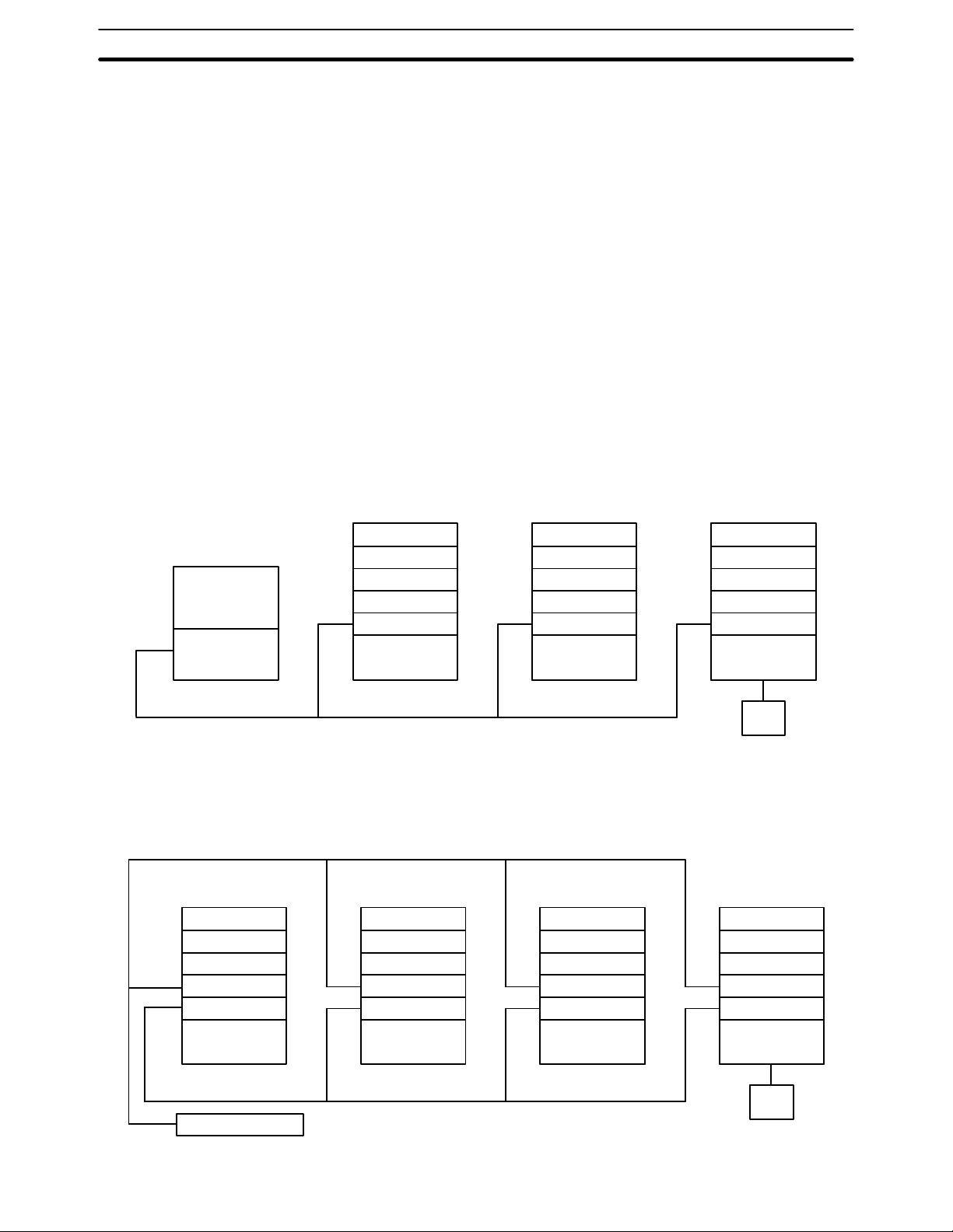
1-3-1 Single-level Systems
The following diagrams show the general configuration of Single-level SYSMAC LINK Systems connected with coaxial and optical fiber cables. The Systems are considered single-level because each PC has only one SYSMAC
LINK Units mounted to it.
The SSS/CVSS connection is not a required part of the System. It is shown
here because of its usefulness in monitoring and controlling not only the
operation of the SYSMAC LINK System itself, but the general operation of all
the PCs connected in the System.
Coaxial System The abbreviation NSB indicates a SYSMAC LINK Network Service Board.
Computer
NSB
CPU Rack
SYSMAC LINK Unit
CPU Unit
CPU Rack
SYSMAC LINK Unit
CPU Unit
CPU Rack
SYSMAC LINK Unit
CPU Unit
CVSS
Note Terminators must be connected to the Units on the ends of the network.
Optical System The abbreviation APS indicates an Auxiliary Power Supply Unit.
CPU Rack
CPU Rack
CPU Rack
CPU Rack
SSS/
APS APSAPS APS
SYSMAC LINK Unit
CPU Unit
Backup Power Supply
SYSMAC LINK Unit
CPU Unit
SYSMAC LINK Unit
CPU Unit
SYSMAC LINK Unit
CPU Unit
SSS/
CVSS
4

System Configuration Section 1-3
1-3-2 Multilevel System
Each PC can have up to two SYSMAC LINK Units mounted. Each SYSMAC
LINK Unit will connect it to a SYSMAC LINK Network, i.e., if a PC has two
SYSMAC LINK Units mounted, it is part of two SYSMAC LINK Networks and
the overall system is considered a Multilevel SYSMAC LINK System. Operating levels, which are described later in this manual, are used to differentiate
between the two Networks to which one PC might belong.
The SSS/CVSS connection is not a required part of the System. It is shown
here because of its usefulness in monitoring and controlling not only the
operation of the SYSMAC LINK System itself, but the general operation of all
the PCs connected in the same Network(s) as the PC to which the SSS/
CVSS is connected.
The abbreviation SLK indicates a SYSMAC LINK Unit.
Subsystem 1
operating level 1
CPU Rack
SYSMAC LINK Unit
SYSMAC LINK Unit
CPU Unit
Subsystem 2
operating level 0
SSS/
CVSS
CPU Rack
SYSMAC LINK Unit
CPU Unit
CPU Rack
SYSMAC LINK Unit
CPU Unit
CPU Rack
SYSMAC LINK Unit
CPU Unit
CPU Rack
SYSMAC LINK Unit
SYSMAC LINK Unit
CPU Unit
CPU Rack
SYSMAC LINK Unit
CPU Unit
SSS/
CVSS
Subsystem 3
operating level 1
CPU Rack
SYSMAC LINK Unit
CPU Unit
Note Terminators must be connected to the Units on the ends of networks connected
by coaxial cable.
5

C200HG CPU33 E
Unit Compatibility Section 1-4
1-4 Unit Compatibility
There are some restrictions regarding the models and versions of PCs to
which SYSMAC LINK Units can be mounted. There are also limitations in
using SYSMAC LINK Units together with other Link Units. These limitations
are described in this section.
1-4-1 Compatibility with PCs
The following table shows which CPU Units are compatible with which SYSMAC LINK Units. The SYSMAC LINK Units cannot be used with other CPU
Units or with a C2000H Duplex System (even one set for Simplex operation.)
A Communications Board equipped with a Link Interface (C200HWCOM01/04-EV1) is required to mount a SYSMAC LINK Unit to a C200HX,
C200HG, or C200HE PC.
SYSMAC LINK Unit Cable Applicable CPU Unit(s)
C1000H-SLK21-V1 Coaxial C1000H-CPU01-EV1 or
C1000H-SLK11 Optical fiber
C200HW-SLK23
C200HW-SLK24
C200HW-SLK13
C200HW-SLK14
Coaxial
Optical fiber
C2000H-CPU01-EV1
C200H-CPU11-E
C200H-CPU31-E
C200HS-CPU31-E
C200HS-CPU33-E
C200HE-CPU32-E
C200HE-CPU42-E
C200HG-CPU33-E
C200HG-CPU43-E
C200HG-CPU53-E
C200HG-CPU63-E
C200HX-CPU34-E
C200HX-CPU44-E
C200HX-CPU54-E
C200HX-CPU64-E
1-4-2 Compatibility with Other Link Units
C1000H-SLK11 and C1000H-SLK21-V1
6
1, 2, 3...
The following combinations of Units can be mounted on a single C1000H or
C2000H PC.
1. Two SYSMAC LINK Units
2. One SYSMAC LINK Unit and one SYSMAC NET Link Unit
3. One SYSMAC LINK Unit and one Rack-mounting Host Link Unit
In addition to the Units in the above combinations you may also mount one
CPU Unit-mounting Host Unit or up to two PC Link Units. Only one PC Link
Unit can be mounted on the C500-BC081 and C500-BC051 Backplanes,
because these Backplanes have only 3 linkable slots.

Unit Compatibility Section 1-4
When combining Units as shown above, use the following models.
Name Model Remarks
SYSMAC LINK Unit C1000H-SLK11 Optical type
C1000H-SLK21-V1 Coaxial type
SYSMAC NET Link Unit C500-SNT31-V4 Other versions cannot
be used.
Rack-mounting Host Link Units C500-LK103
C500-LK103-P
C500-LK203
CPU Unit-mounting Host Link
Units
PC Link Units C500-LK009-V1
Caution Be sure to set a unique operating level for each system when combining SYS-
!
3G2A6-LK101-EV1
3G2A6-LK101-PEV1
3G2A6-LK201-EV1
3G2A6-LK202-EV1
C500-LK009
MAC LINK Units, SYSMAC NET Link Units, and/or Host Link Units (SYSMAC
WAY) on the same PC.
Other versions cannot
be used.
---
---
C200HW-SLK13, C200HW-SLK14, C200HW-SLK23, and C200HW-SLK24
The following combinations of Units can be mounted on a single PC. Some
power supplies might not have sufficient capacity for all system configurations; be sure to check power supply requirements and capacities carefully.
1, 2, 3...
1. Two SYSMAC LINK Units
2. One SYSMAC LINK Unit and one SYSMAC NET Link Unit
In addition to the Units in the above combinations you may also mount one
CPU Unit-mounting Host Link Unit, up to two rack-mounting Host Link Units,
or up to two PC Link Units. For the C200HX, C200HG, or C200HE PC, one
SYSMAC LINK Unit and one PC Card Unit may be mounted.
When combining Units as shown above, use the following models.
Name Model Remarks
SYSMAC LINK Unit C200HW-SLK13
C200HW-SLK14
C200HW-SLK23
C200HW-SLK24
SYSMAC NET Link Unit C200HS-SNT32 ---
PC Card Unit C200HW-PCU01 Can be used only with
Rack-mounting Host Link Units C200H-LK101 (-PV1)
C200H-LK201-V1
C200H-LK202-V1
CPU Unit-mounting Host Link
Units
PC Link Units C200H-LK401 ---
3G2A6-LK101-EV1
3G2A6-LK101-PEV1
3G2A6-LK201-EV1
3G2A6-LK202-EV1
Optical type
Coaxial type
with the C200HX,
C200HG, or C200HE.
---
Cannot be used with
the C200HS, C200HX,
C200HG, or C200HE.
Note Be sure to set a unique operating level for each system when combining SYS-
MAC LINK Systems, SYSMAC NET Link Systems, and the PC Card Unit on the
same PC.
7

Precautions Section 1-5
1-5 Precautions
• A Bus Connector is required to mount the C200HW-SLK13, C200HW-SLK14,
C200HW-SLK23, or C200HW-SLK24. Refer to
details.
• Be sure to set different operating levels when mounting a SYSMAC LINK Unit
on the same PC with a SYSMAC NET Link Unit, Host Link Unit (Rack-mounting type), or PC Card Unit. Refer to
Settings
• The input interrupt response speed is 1 ms max. for the C200HW-SLK13,
C200HW-SLK14, C200HW-SLK23, or C200HW-SLK24 when mounted to the
C200HX/HG/HE and 10 ms max. when mounted to the C200H or C200HS.
• The C200HW-SLK13, C200HW-SLK14, C200HW-SLK23, or C200HWSLK24 are totally upwardly compatible from the C200HS-SLK12 and
C200HS-SLK22.
• The power supply capacity depends on the CPU Unit that is being used. Refer
to you PC’s
capacity.
for details.
Installation Guide
for details and do not run over the power supply
Section 2 Unit Components and Switch
Section 3 Installation
for
8

SECTION 2
Unit Components and Switch Settings
The names and functions of the SYSMAC LINK Units’ components and switch settings are described in this section.
2-1 C1000H-SLK11/SLK21-V1 Components 10. . . . . . . . . . . . . . . . . . . . . . . . . . . . . . . . . . . . . .
2-2 C200HW-SLK13/14/23/24 Components 12. . . . . . . . . . . . . . . . . . . . . . . . . . . . . . . . . . . . . . .
2-3 Indicators 13. . . . . . . . . . . . . . . . . . . . . . . . . . . . . . . . . . . . . . . . . . . . . . . . . . . . . . . . . . . . . . .
2-4 Switches 14. . . . . . . . . . . . . . . . . . . . . . . . . . . . . . . . . . . . . . . . . . . . . . . . . . . . . . . . . . . . . . . .
2-4-1 C1000H-SLK11/SLK21-V1 14. . . . . . . . . . . . . . . . . . . . . . . . . . . . . . . . . . . . . . . . .
2-4-2 C200HW-SLK13/14/23/24 14. . . . . . . . . . . . . . . . . . . . . . . . . . . . . . . . . . . . . . . . . .
2-5 Setting Switches 15. . . . . . . . . . . . . . . . . . . . . . . . . . . . . . . . . . . . . . . . . . . . . . . . . . . . . . . . . .
2-5-1 Node Number Switches 15. . . . . . . . . . . . . . . . . . . . . . . . . . . . . . . . . . . . . . . . . . . . .
2-5-2 C1000H-SLK11/SLK21-V1 DIP Switch 1 16. . . . . . . . . . . . . . . . . . . . . . . . . . . . . .
2-5-3 C200HW-SLK13/14/23/24 DIP Switches 1 and 2 16. . . . . . . . . . . . . . . . . . . . . . . .
9
C1000H-SLK11/SLK21-V1 Components Section 2-1
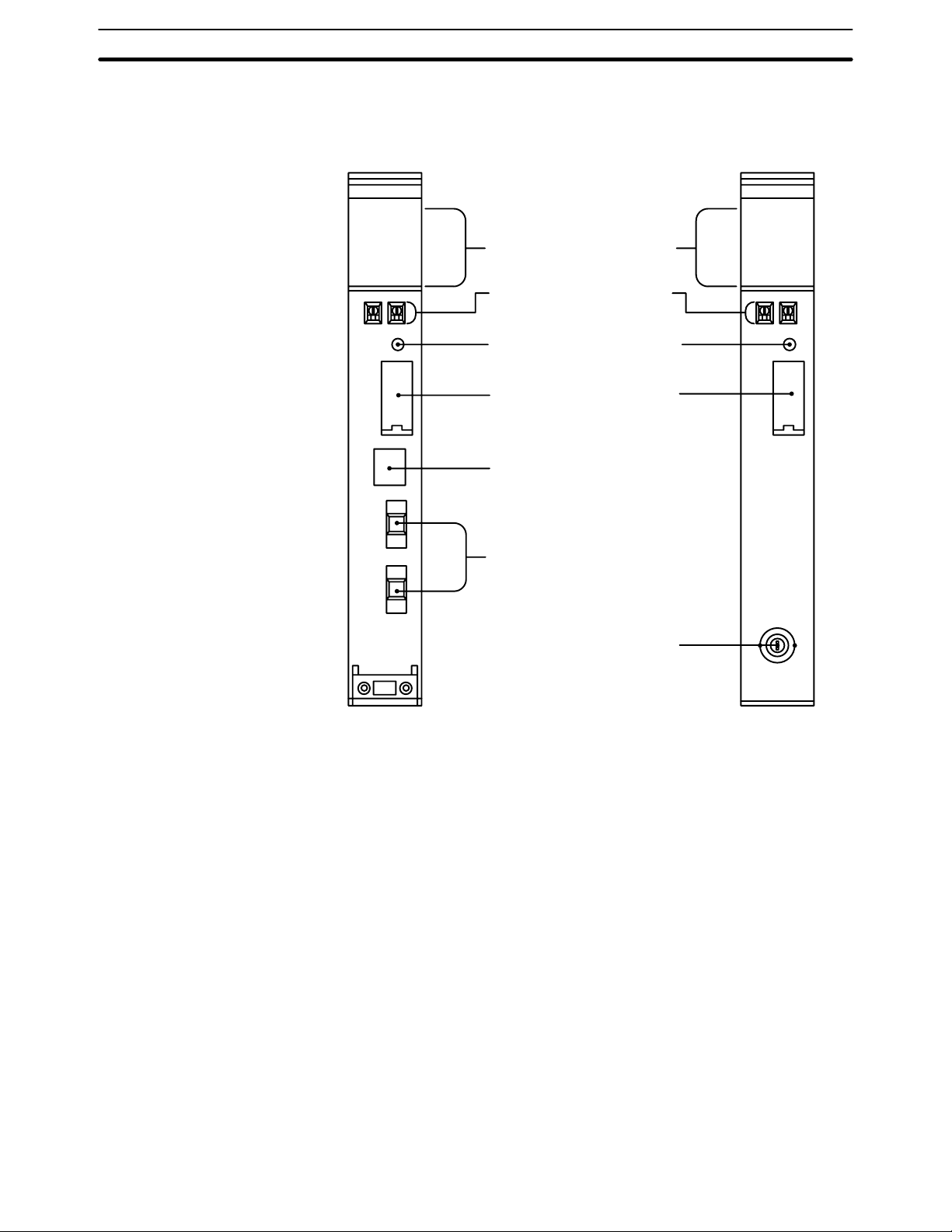
2-1 C1000H-SLK11/SLK21-V1 Components
Front
C1000H-SLK11 C1000H-SLK21-V1
SLK11
RUN
ERC
INS
SD
TS
P/S
ERH
M/S
RD
LNK
Indicators
Indicate operational status.
Node number switches
Used to set the node number.
Reset switch
Used to reinitialize the SYSMAC
LINK Unit.
DIP switch 1
Remove this cover to gain access to
DIP switch 1. The switch is used to set
a variety of operating parameters.
Power supply connector
Connect to the Auxiliary Power
Supply Unit.
Optical fiber connectors
Used to connect optical fiber cables.
SLK21-V1
RUN
ERC
INS
SD
TS
ERH
M/S
RD
LNK
Coaxial connector
Used to connect coaxial cable.
Note Do not push the Reset Switch on SYSMAC LINK Units when the RUN indicator is
not lit (watchdog timer error).
10
C1000H-SLK11/SLK21-V1 Components Section 2-1
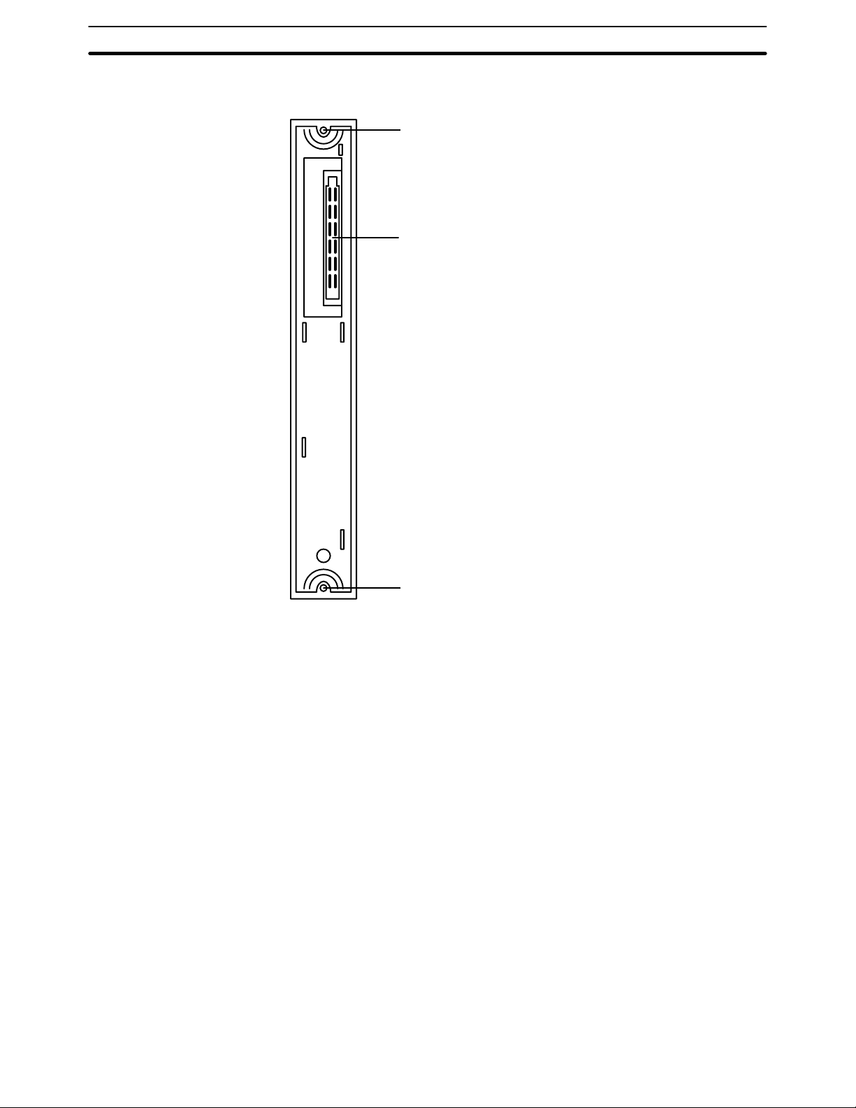
Back
The backs of the C1000H-SLK11 and C1000H-SLK21-V1 are identical.
Mounting screw
Secures Unit to Backplane
Connector
Used to connect the SYSMAC
LINK Unit to the Rack.
Mounting screw
Secures Unit to Backplane
11
C200HW-SLK13/14/23/24 Components Section 2-2
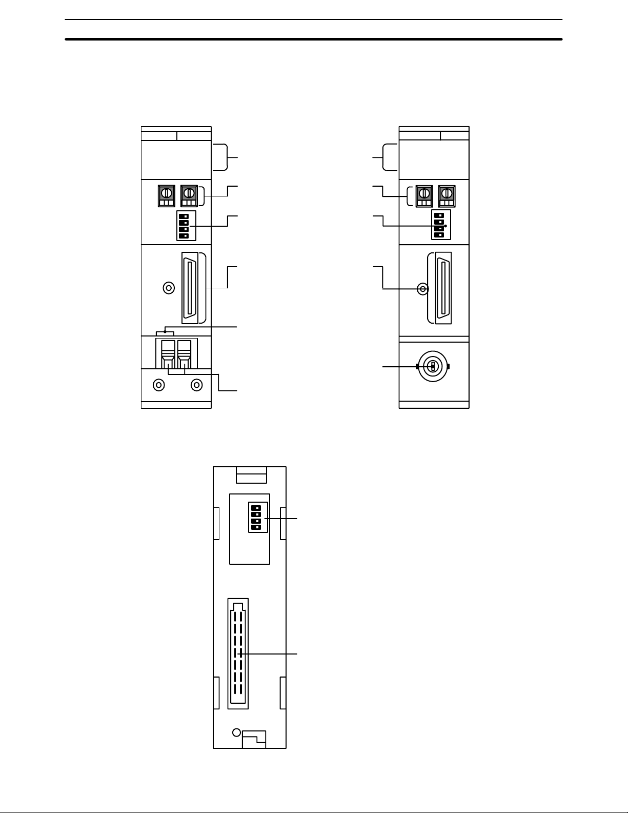
2-2 C200HW-SLK13/14/23/24 Components
Front
C200HW-SLK13/14 C200HW-SLK23/24
SLK14
RUN
ERC
INS
SD
P/S
ERH
M/S
RD
TS
LNK
Indicators
Indicate operational status.
Node number switches
Used to set node number.
DIP switch 1
Remove this cover to gain access to
DIP switch 1. The switch is used to set
a variety of operating parameters.
SYSMAC LINK Unit Connector
Used to connect the SYSMAC
LINK Unit to the CPU Unit.
Power supply connector
Connect to the Auxiliary Power
Supply Unit.
Coaxial connector
Used to connect coaxial cable.
Optical fiber connectors
Used to connect optical fiber cables.
SLK24
RUN
ERC
INS
SD
ERH
M/S
RD
TS
LNK
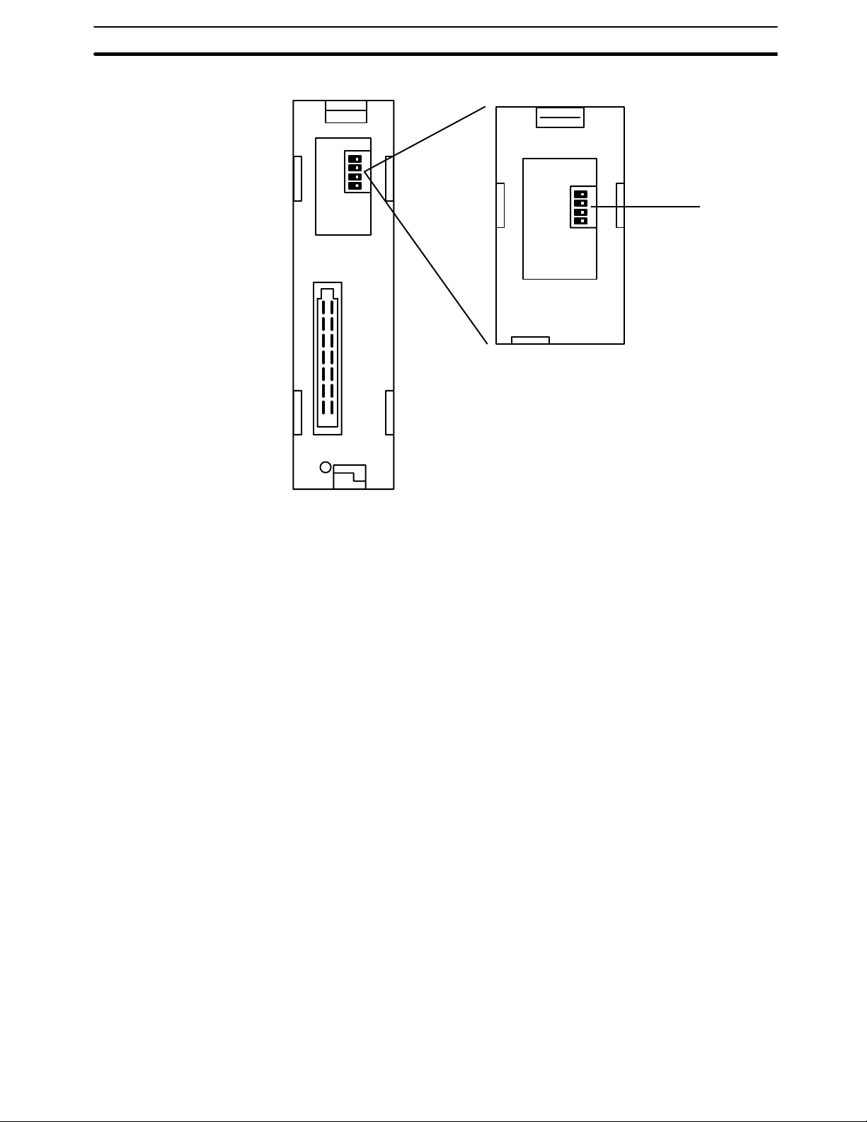
Back The backs of the C200HW-SLK13/14 and C200HW-SLK23/24 are identical.
DIP switch 2
Used to set a variety of
operating parameters.
Connector
Used to connect the
SYSMAC LINK Unit
to the Rack.
12
Indicators Section 2-3
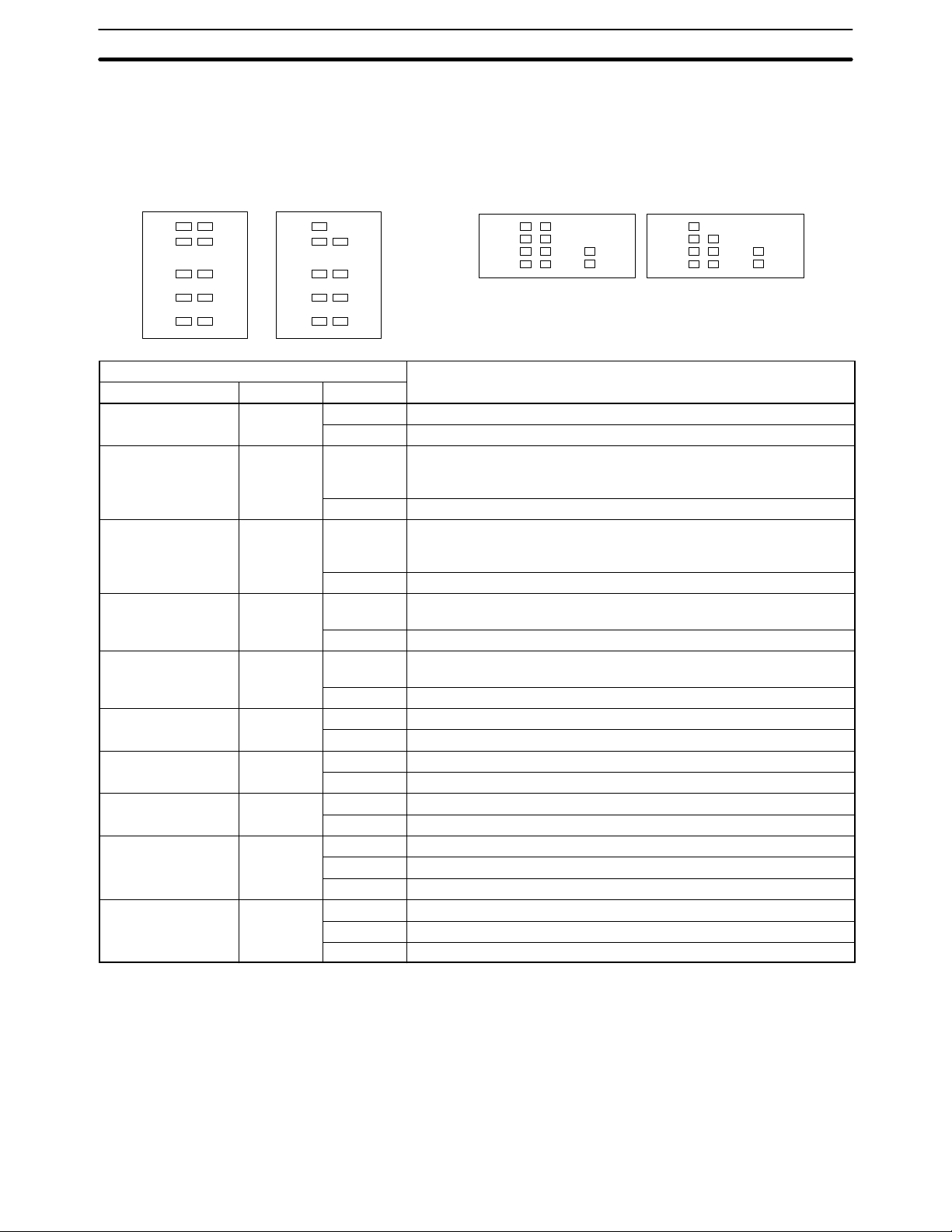
2-3 Indicators
The status of the SYSMAC LINK Unit is indicated by the indicators shown below.
The Units that use coaxial cables (C1000H-SLK21-V1 and C200HW-SLK23/24)
are not equipped with the P/S indicator.
C1000H-SLK11 C1000H-SLK21-V1
RUN
ERC
INS
SD
TS
P/S
ERH
M/S
RD
LNK
RUN
ERC
INS
SD
TS
ERH
M/S
RD
LNK
C200HW-SLK13/14 C200HW-SLK23/24
RUN
ERC
INS
SD
P/S
ERH
M/S
RD
TS
LNK
RUN
ERC
INS
SD
ERH
M/S
RD
TS
LNK
Indicator Meaning
Name Color Condition
RUN Green Lit Unit is operating normally.
Not lit Watchdog timer error has occurred.
P/S
Green Lit Power is being supplied from the Auxiliary Power Supply Unit.
(power supply on,
optical units only)
Not lit Power is not being supplied from the Auxiliary Power Supply Unit.
ERC
(communications
Red Lit Communications error has occurred, node number setting is incorrect,
or same node number has been set twice.
error)
Not lit None of the above errors has occurred.
ERH (PC error) Red Lit PC CPU, PC model, PC version, PC interface, or EEPROM error has
occurred.
Not lit None of the above errors has occurred.
INS (Network
Orange Lit Unit is part of Network.
inclusion)
Not lit Unit is not part of Network.
M/S (polling unit) Orange Lit Unit is polling unit.
Not lit Unit is not part of Network or is polled unit.
SD (transfer) Orange Lit Unit is sending data.
Not lit Unit is not sending data.
RD (receive) Orange Lit Unit is receiving data.
Not lit Unit is not receiving data
TS (test) Orange Lit Test is being executed.
Flashing Test setting error has occurred.
Not lit Test is not being executed.
LNK (data link) Orange Lit Unit is part of active data link.
Flashing Data link error has occurred.
Not lit Unit is not part of active data link.
13
Switches Section 2-4
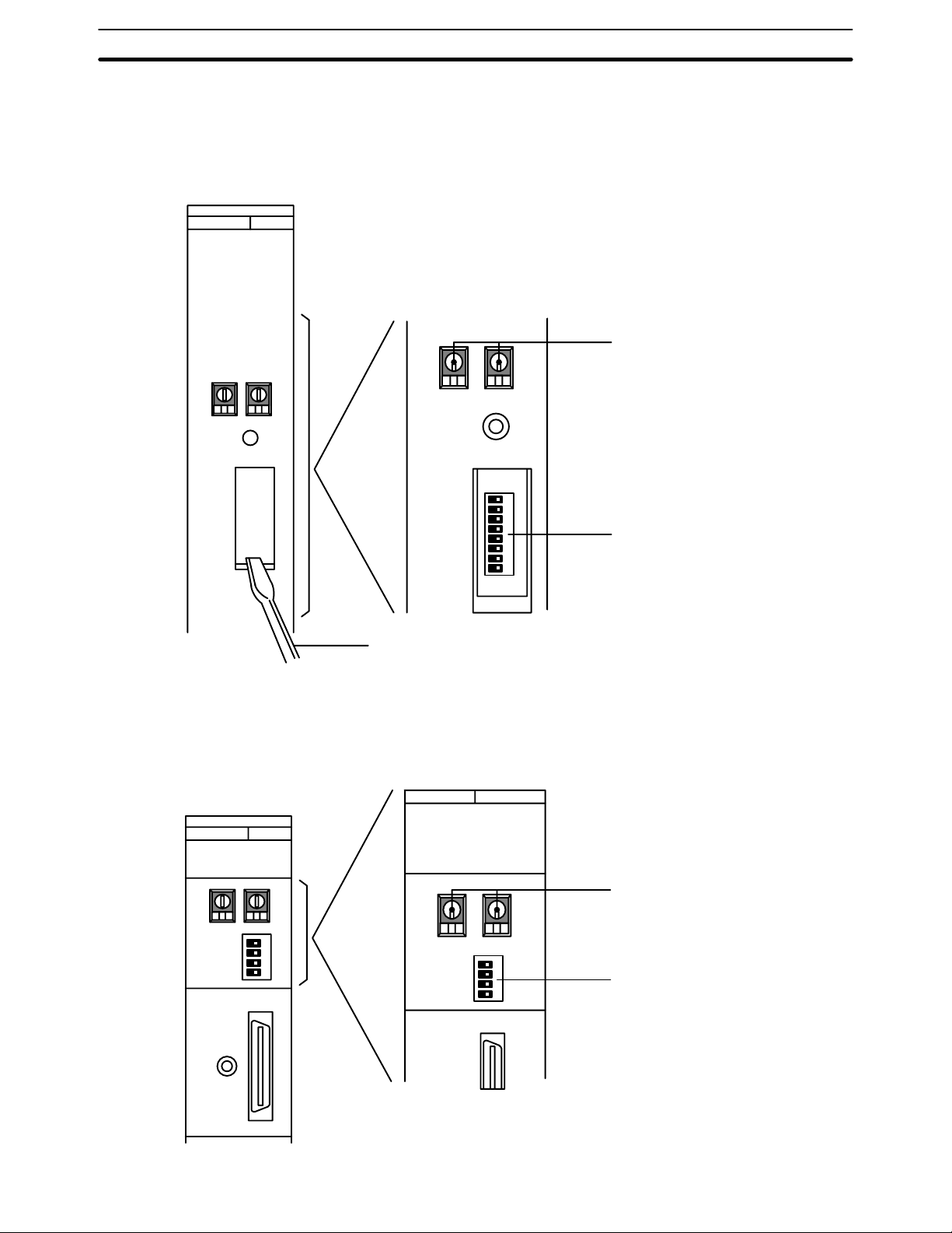
2-4 Switches
2-4-1 C1000H-SLK11/SLK21-V1
DIP switch 1 can be accessed by removing the cover from the front of the
Unit with a standard screwdriver.
Standard screwdriver
2-4-2 C200HW-SLK13/14/23/24
The node number switches and DIP switch 1 are located on the front of the
Unit, and DIP switch 2 is located on the back.
Front
x10
NODE NO.
1
RESET
SW
Node number switches
0
x10
8
7
6
5
4
3
2
1
Used to set node number.
DIP switch 1
14
x10
NODE NO.
1
SW
Node number switches
0
x10
4
3
2
1
Used to set node number.
DIP switch 1
Setting Switches Section 2-5
Back
4
3
2
1
DIP switch 2
2-5 Setting Switches
Switch settings determine how the SYSMAC LINK Units will work together in
a Network. Be sure to turn the power off to the PC before setting the
switches. Errors in switch settings, which may not always be detected by the
System, can cause faulty data communications. Set and check all switch settings carefully.
2-5-1 Node Number Switches
Turn off the power to the PC before setting the node number switches. Node
number switches determine the node number. The left switch sets the tens
digit; the right switch sets the ones digit. The node number must be between
01 and 62. Each SYSMAC LINK Unit in a Network must have a unique node
number.
Use a small flat-blade screwdriver to set node number switches, being careful not to damage them.
Note Units in the same network must have unique node numbers.
15

Setting Switches Section 2-5
2-5-2 C1000H-SLK11/SLK21-V1 DIP Switch 1
Turn off the power to the PC before setting the DIP switch. DIP switch 1 is
used to control the communications test, data link activation, operating level,
PC operating mode when power is applied, network parameter initialization,
and polling/polled unit operation. Refer to the pages indicated in the table for
more details on these settings.
Pin Function Page
When ON When OFF
1 Test activated. Test stopped. 111
2 Data link activated. Data link stopped. 58
3 Operating level 0 Operating level 1 38
1
4
5 PC enters MONITOR mode at
1
6
2
7
2
8
For maintenance use only. Leave this switch set to OFF. ---
PC enters usual mode at
start-up.
Not used. Leave this switch set to OFF. ---
Network Parameters initialized. Network Parameters not initial-
Polled unit Polling unit 39
start-up.
ized.
38
40
Note 1. Pins 4 and 6 should always be OFF.
2. Pins 7 and 8 are normally OFF.
2-5-3 C200HW-SLK13/14/23/24 DIP Switches 1 and 2
Turn off the power to the PC before setting the DIP switches. DIP switch 1 is
used to control the communications test, data link activation, and operating
level. DIP switch 2 is used to control network parameter initialization and polling/polled unit operation Refer to the pages indicated in the tables for more
details on these settings.
DIP Switch 1
(Front of the Unit)
Note *Pin 4 should always be OFF.
DIP Switch 2
(Back of the Unit)
Pin Function Page
When ON When OFF
1 Test activated. Test stopped. 111
2 Data link activated. Data link stopped. 58
3 Operating level 0 Operating level 1 38
4* For maintenance use only. Leave this switch set to OFF. ---
Pin Function Page
When ON When OFF
1
1
1
2
2
3
2
4
Not used. Leave this switch set to OFF. ---
Not used. Leave this switch set to OFF. ---
Network Parameters initialized. Network Parameters not initial-
ized.
Polled unit Polling unit 39
40
16
Note 1. Pins 1 and 2 should always be OFF.
2. Pins 3 and 4 are normally OFF.
 Loading...