

Page 1

Cat. No. W139-E1-04
SYSMAC
Programmable Controllers
C1000H/C2000H
INSTALLATION GUIDE
Page 2

C1000H/C2000H
Programmable Controllers
Installation Guide
Revised June 2000
Page 3

Terms and Conditions of Sale
1. Offer; Acceptance. These terms and conditions (these "Terms") are deemed
part of all quotes, agreements, purchase orders, acknowledgments, price lists,
catalogs, manuals, brochures and other documents, whether electronic or in
writing, relating to the sale of products or services (collectively, the "Products
by Omron Electronics LLC and its subsidiary companies (“Omron
objects to any terms or conditions proposed in Buyer’s purchase order or other
documents which are inconsistent with, or in addition to, these Terms.
2. Prices; Payment Terms.
out notice by Omron. Omron reserves the right to increase or decrease prices
on any unshipped portions of outstanding orders. Payments for Products are
due net 30 days unless otherwise stated in the invoice.
3. Discounts.
sent to Buyer after deducting transportation charges, taxes and duties, and will
be allowed only if (i) the invoice is paid according to Omron’s payment terms
and (ii) Buyer has no past due amounts.
4. Interest.
the maximum legal rate, whichever is less, on any balance not paid within the
stated terms.
5. Orders
6. Governmental Approvals.
costs involved in, obtaining any government approvals required for the importation or sale of the Products.
7. Taxes
real property and income taxes), including any interest or penalties thereon,
imposed directly or indirectly on Omron or required to be collected directly or
indirectly by Omron for the manufacture, production, sale, delivery, importation, consumption or use of the Products sold hereunder (including customs
duties and sales, excise, use, turnover and license taxes) shall be charged to
and remitted by Buyer to Omron.
8. Financial.
to Omron, Omron reserves the right to stop shipments or require satisfactory
security or payment in advance. If Buyer fails to make payment or otherwise
comply with these Terms or any related agreement, Omron may (without liability and in addition to other remedies) cancel any unshipped portion of Products sold hereunder and stop any Products in transit until Buyer pays all
amounts, including amounts payable hereunder, whether or not then due,
which are owing to it by Buyer. Buyer shall in any event remain liable for all
unpaid accounts.
9. Cancellation; Etc.
unless Buyer indemnifies Omron against all related costs or expenses.
10. Force Majeure
resulting from causes beyond its control, including earthquakes, fires, floods,
strikes or other labor disputes, shortage of labor or materials, accidents to
machinery, acts of sabotage, riots, delay in or lack of transportation or the
requirements of any government authority.
11. Shipping; Delivery.
a. Shipments shall be by a carrier selected by Omron; Omron will not drop ship
b. Such carrier shall act as the agent of Buyer and delivery to such carrier shall
c. All sales and shipments of Products shall be FOB shipping point (unless oth-
d. Delivery and shipping dates are estimates only; and
e. Omron will package Products as it deems proper for protection against nor-
12. Claims.
Products occurring before delivery to the carrier must be presented in writing
to Omron within 30 days of receipt of shipment and include the original transportation bill signed by the carrier noting that the carrier received the Products
from Omron in the condition claimed.
13. Warranties
Products will be free from defects in materials and workmanship for a period of
twelve months from the date of sale by Omron (or such other period expressed
in writing by Omron). Omron disclaims all other warranties, express or implied.
(b) Limitations
EXPRESS OR IMPLIED, ABOUT NON-INFRINGEMENT, MERCHANTABIL-
Cash discounts, if any, will apply only on the net amount of invoices
Omron, at its option, may charge Buyer 1-1/2% interest per month or
. Omron will accept no order less than $200 net billing.
. All taxes, duties and other governmental charges (other than general
If the financial position of Buyer at any time becomes unsatisfactory
except in “break down” situations.
constitute delivery to Buyer;
erwise stated in writing by Omron), at which point title and risk of loss shall
pass from Omron to Buyer; provided that Omron shall retain a security interest in the Products until the full purchase price is paid;
mal handling and extra charges apply to special conditions.
Any claim by Buyer against Omron for shortage or damage to the
. (a) Exclusive Warranty. Omron’s exclusive warranty is that the
All prices stated are current, subject to change with-
Buyer shall be responsible for, and shall bear all
Orders are not subject to rescheduling or cancellation
. Omron shall not be liable for any delay or failure in delivery
Unless otherwise expressly agreed in writing by Omron:
. OMRON MAKES NO WARRANTY OR REPRESENTATION,
”). Omron
ITY OR FITNESS FOR A PARTICULAR PURPOSE OF THE PRODUCTS.
BUYER ACKNOWLEDGES THAT IT ALONE HAS DETERMINED THAT THE
PRODUCTS WILL SUITABLY MEET THE REQUIREMENTS OF THEIR
")
INTENDED USE. Omron further disclaims all warranties and responsibility of
any type for claims or expenses based on infringement by the Products or otherwise of any intellectual property right. (c) Buyer Remedy
gation hereunder shall be, at Omron’s election, to (i) replace (in the form
originally shipped with Buyer responsible for labor charges for removal or
replacement thereof) the non-complying Product, (ii) repair the non-complying
Product, or (iii) repay or credit Buyer an amount equal to the purchase price of
the non-complying Product; provided that in no event shall Omron be responsible for warranty, repair, indemnity or any other claims or expenses regarding
the Products unless Omron’s analysis confirms that the Products were properly handled, stored, installed and maintained and not subject to contamination, abuse, misuse or inappropriate modification. Return of any Products by
Buyer must be approved in writing by Omron before shipment. Omron Companies shall not be liable for the suitability or unsuitability or the results from the
use of Products in combination with any electrical or electronic components,
circuits, system assemblies or any other materials or substances or environments. Any advice, recommendations or information given orally or in writing,
are not to be construed as an amendment or addition to the above warranty.
See http://oeweb.omron.com or contact your Omron representative for published information.
14. Limitation on Liability; Etc
FOR SPECIAL, INDIRECT, INCIDENTAL, OR CONSEQUENTIAL DAMAGES,
LOSS OF PROFITS OR PRODUCTION OR COMMERCIAL LOSS IN ANY
WAY CONNECTED WITH THE PRODUCTS, WHETHER SUCH CLAIM IS
BASED IN CONTRACT, WARRANTY, NEGLIGENCE OR STRICT LIABILITY.
Further, in no event shall liability of Omron Companies exceed the individual
price of the Product on which liability is asserted.
15. Indemnities
their employees from and against all liabilities, losses, claims, costs and
expenses (including attorney's fees and expenses) related to any claim, investigation, litigation or proceeding (whether or not Omron is a party) which arises
or is alleged to arise from Buyer's acts or omissions under these Terms or in
any way with respect to the Products. Without limiting the foregoing, Buyer (at
its own expense) shall indemnify and hold harmless Omron and defend or settle any action brought against such Companies to the extent based on a claim
that any Product made to Buyer specifications infringed intellectual property
rights of another party.
16. Property; Confidentiality.
sive property of Omron Companies and Buyer shall not attempt to duplicate it
in any way without the written permission of Omron. Notwithstanding any
charges to Buyer for engineering or tooling, all engineering and tooling shall
remain the exclusive property of Omron. All information and materials supplied
by Omron to Buyer relating to the Products are confidential and proprietary,
and Buyer shall limit distribution thereof to its trusted employees and strictly
prevent disclosure to any third party.
17. Export Controls.
licenses regarding (i) export of products or information; (iii) sale of products to
“forbidden” or other proscribed persons; and (ii) disclosure to non-citizens of
regulated technology or information.
18. Miscellaneous
and no course of dealing between Buyer and Omron shall operate as a waiver
of rights by Omron. (b) Assignment
without Omron's written consent. (c) Law.
law of the jurisdiction of the home office of the Omron company from which
Buyer is purchasing the Products (without regard to conflict of law principles). (d) Amendment
Buyer and Omron relating to the Products, and no provision may be changed
or waived unless in writing signed by the parties. (e) Severability
sion hereof is rendered ineffective or invalid, such provision shall not invalidate
any other provision. (f) Setoff
against the amount owing in respect of this invoice. (g) Definitions
herein, “including
nies” (or similar words) mean Omron Corporation and any direct or indirect
subsidiary or affiliate thereof.
. Buyer shall indemnify and hold harmless Omron Companies and
Buyer shall comply with all applicable laws, regulations and
. (a) Waiver. No failure or delay by Omron in exercising any right
. OMRON COMPANIES SHALL NOT BE LIABLE
Any intellectual property in the Products is the exclu-
. Buyer may not assign its rights hereunder
These Terms are governed by the
. These Terms constitute the entire agreement between
. Buyer shall have no right to set off any amounts
” means “including without limitation”; and “Omron Compa-
. Omron’s sole obli-
. If any provi-
. As used
Certain Precautions on Specifications and Use
1. Suitability of Use. Omron Companies shall not be responsible for conformity
with any standards, codes or regulations which apply to the combination of the
Product in the Buyer’s application or use of the Product. At Buyer’s request,
Omron will provide applicable third party certification documents identifying
ratings and limitations of use which apply to the Product. This information by
itself is not sufficient for a complete determination of the suitability of the Product in combination with the end product, machine, system, or other application
or use. Buyer shall be solely responsible for determining appropriateness of
the particular Product with respect to Buyer’s application, product or system.
Buyer shall take application responsibility in all cases but the following is a
non-exhaustive list of applications for which particular attention must be given:
(i) Outdoor use, uses involving potential chemical contamination or electrical
interference, or conditions or uses not described in this document.
(ii) Use in consumer products or any use in significant quantities.
(iii) Energy control systems, combustion systems, railroad systems, aviation
systems, medical equipment, amusement machines, vehicles, safety equipment, and installations subject to separate industry or government regulations.
(iv) Systems, machines and equipment that could present a risk to life or property. Please know and observe all prohibitions of use applicable to this Product.
NEVER USE THE PRODUCT FOR AN APPLICATION INVOLVING SERIOUS
RISK TO LIFE OR PROPERTY OR IN LARGE QUANTITIES WITHOUT
ENSURING THAT THE SYSTEM AS A WHOLE HAS BEEN DESIGNED TO
iv
ADDRESS THE RISKS, AND THAT THE OMRON’S PRODUCT IS PROPERLY RATED AND INSTALLED FOR THE INTENDED USE WITHIN THE
OVERALL EQUIPMENT OR SYSTEM.
2. Programmable Products.
user’s programming of a programmable Product, or any consequence thereof.
3. Performance Data
and other materials is provided as a guide for the user in determining suitability and does not constitute a warranty. It may represent the result of Omron’s
test conditions, and the user must correlate it to actual application requirements. Actual performance is subject to the Omron’s Warranty and Limitations
of Liability.
4. Change in Specifications
changed at any time based on improvements and other reasons. It is our practice to change part numbers when published ratings or features are changed,
or when significant construction changes are made. However, some specifications of the Product may be changed without any notice. When in doubt, special part numbers may be assigned to fix or establish key specifications for
your application. Please consult with your Omron’s representative at any time
to confirm actual specifications of purchased Product.
5. Errors and Omissions.
checked and is believed to be accurate; however, no responsibility is assumed
for clerical, typographical or proofreading errors or omissions.
Omron Companies shall not be responsible for the
. Data presented in Omron Company websites, catalogs
. Product specifications and accessories may be
Information presented by Omron Companies has been
Page 4

Notice:
OMRON products are manufactured for use according to proper procedures by a qualified operator
and only for the purposes described in this manual.
The following conventions are used to indicate and classify precautions in this manual. Always heed
the information provided with them. Failure to heed precautions can result in injury to people or damage to property.
DANGER Indicates an imminently hazardous situation which, if not avoided, will result in death or
!
serious injury.
WARNING Indicates a potentially hazardous situation which, if not avoided, could result in death or
!
serious injury.
Caution Indicates a potentially hazardous situation which, if not avoided, may result in minor or
!
moderate injury, or property damage.
OMRON Product References
All OMRON products are capitalized in this manual. The word “Unit” is also capitalized when it refers
to an OMRON product, regardless of whether or not it appears in the proper name of the product.
The abbreviation “Ch,” which appears in some displays and on some OMRON products, often means
“word” and is abbreviated “Wd” in documentation in this sense.
The abbreviation “PC” means Programmable Controller and is not used as an abbreviation for anything else.
Visual Aids
The following headings appear in the left column of the manual to help you locate different types of
information.
©OMRON, 1988
All rights reserved. No part of this publication may be reproduced, photocopied or recorded, stored in a retrieval system or
transmitted in any form or by any means mechanical, electronic, or otherwise, without the prior written permission of OMRON.
No patent liability is assumed with respect to the use of the information contained herein. Moreover, because OMRON is con-
stantly striving to improve its high−quality products, the information contained in this manual is subject to change without no-
tice. Every precaution has been taken in the preparation of this manual; nevertheless, OMRON assumes no responsibility for
errors or omissions. Neither is any liability assumed for damages resulting from the use of the information contained in this
publication.
Note Indicates information of particular interest for efficient and convenient operation
of the product.
1, 2, 3... 1. Indicates lists of one sort or another, such as procedures, checklists, etc.
v
Page 5

vi
Page 6

TABLE OF CONTENTS
PRECAUTIONS xi. . . . . . . . . . . . . . . . . . . . . . . . . . . . . . . . .
1 Intended Audience xii. . . . . . . . . . . . . . . . . . . . . . . . . . . . . . . . . . . . . . . . . . . . . . . . . . . . . . . . . . .
2 General Precautions xii. . . . . . . . . . . . . . . . . . . . . . . . . . . . . . . . . . . . . . . . . . . . . . . . . . . . . . . . . .
3 Safety Precautions xii. . . . . . . . . . . . . . . . . . . . . . . . . . . . . . . . . . . . . . . . . . . . . . . . . . . . . . . . . . .
4 Operating Environment Precautions xii. . . . . . . . . . . . . . . . . . . . . . . . . . . . . . . . . . . . . . . . . . . . .
5 Application Precautions xiii. . . . . . . . . . . . . . . . . . . . . . . . . . . . . . . . . . . . . . . . . . . . . . . . . . . . . .
SECTION 1
Introduction 1. . . . . . . . . . . . . . . . . . . . . . . . . . . . . . . . . . . .
1-1 What is a Control System? 2. . . . . . . . . . . . . . . . . . . . . . . . . . . . . . . . . . . . . . . . . . . . . . . . .
1-2 The Role of the PC 3. . . . . . . . . . . . . . . . . . . . . . . . . . . . . . . . . . . . . . . . . . . . . . . . . . . . . . .
1-3 How Does a PC Work? 5. . . . . . . . . . . . . . . . . . . . . . . . . . . . . . . . . . . . . . . . . . . . . . . . . . . .
1-4 Available Manuals 7. . . . . . . . . . . . . . . . . . . . . . . . . . . . . . . . . . . . . . . . . . . . . . . . . . . . . . .
SECTION 2
Description of All Components 9. . . . . . . . . . . . . . . . . . . . .
2-1 CPU Rack 10. . . . . . . . . . . . . . . . . . . . . . . . . . . . . . . . . . . . . . . . . . . . . . . . . . . . . . . . . . . . . .
2-2 CPU Power Supply 13. . . . . . . . . . . . . . . . . . . . . . . . . . . . . . . . . . . . . . . . . . . . . . . . . . . . . . .
2-3 I/O Backplane 15. . . . . . . . . . . . . . . . . . . . . . . . . . . . . . . . . . . . . . . . . . . . . . . . . . . . . . . . . . .
2-4 Expansion I/O Backplane 16. . . . . . . . . . . . . . . . . . . . . . . . . . . . . . . . . . . . . . . . . . . . . . . . . .
2-5 I/O Power Supply 16. . . . . . . . . . . . . . . . . . . . . . . . . . . . . . . . . . . . . . . . . . . . . . . . . . . . . . . .
2-6 Duplex Unit (C2000H Duplex) 18. . . . . . . . . . . . . . . . . . . . . . . . . . . . . . . . . . . . . . . . . . . . .
2-7 I/O Control Unit 18. . . . . . . . . . . . . . . . . . . . . . . . . . . . . . . . . . . . . . . . . . . . . . . . . . . . . . . . .
2-8 I/O Interface Unit 18. . . . . . . . . . . . . . . . . . . . . . . . . . . . . . . . . . . . . . . . . . . . . . . . . . . . . . . .
2-9 File Memory Unit 19. . . . . . . . . . . . . . . . . . . . . . . . . . . . . . . . . . . . . . . . . . . . . . . . . . . . . . . .
2-10 Space Unit 19. . . . . . . . . . . . . . . . . . . . . . . . . . . . . . . . . . . . . . . . . . . . . . . . . . . . . . . . . . . . .
2-11 I/O Remove Unit 19. . . . . . . . . . . . . . . . . . . . . . . . . . . . . . . . . . . . . . . . . . . . . . . . . . . . . . . .
2-12 I/O Units 20. . . . . . . . . . . . . . . . . . . . . . . . . . . . . . . . . . . . . . . . . . . . . . . . . . . . . . . . . . . . . . .
2-13 Memory Packs 23. . . . . . . . . . . . . . . . . . . . . . . . . . . . . . . . . . . . . . . . . . . . . . . . . . . . . . . . . .
SECTION 3
Assembly 25. . . . . . . . . . . . . . . . . . . . . . . . . . . . . . . . . . . . . . .
3-1 Mounting the Units 26. . . . . . . . . . . . . . . . . . . . . . . . . . . . . . . . . . . . . . . . . . . . . . . . . . . . . . .
3-2 C2000H Duplex System 29. . . . . . . . . . . . . . . . . . . . . . . . . . . . . . . . . . . . . . . . . . . . . . . . . . .
3-3 C2000H Simplex System 32. . . . . . . . . . . . . . . . . . . . . . . . . . . . . . . . . . . . . . . . . . . . . . . . . .
3-4 Memory Packs 32. . . . . . . . . . . . . . . . . . . . . . . . . . . . . . . . . . . . . . . . . . . . . . . . . . . . . . . . . .
3-5 System Configurations 34. . . . . . . . . . . . . . . . . . . . . . . . . . . . . . . . . . . . . . . . . . . . . . . . . . . .
SECTION 4
System Connections 39. . . . . . . . . . . . . . . . . . . . . . . . . . . . . .
4-1 Current Consumption 40. . . . . . . . . . . . . . . . . . . . . . . . . . . . . . . . . . . . . . . . . . . . . . . . . . . . .
4-2 I/O Connections 43. . . . . . . . . . . . . . . . . . . . . . . . . . . . . . . . . . . . . . . . . . . . . . . . . . . . . . . . .
SECTION 5
Installation Environment 47. . . . . . . . . . . . . . . . . . . . . . . . .
5-1 Cooling 48. . . . . . . . . . . . . . . . . . . . . . . . . . . . . . . . . . . . . . . . . . . . . . . . . . . . . . . . . . . . . . . .
5-2 Mounting Requirements 48. . . . . . . . . . . . . . . . . . . . . . . . . . . . . . . . . . . . . . . . . . . . . . . . . . .
5-3 Duct Work 50. . . . . . . . . . . . . . . . . . . . . . . . . . . . . . . . . . . . . . . . . . . . . . . . . . . . . . . . . . . . .
5-4 Preventing Noise 51. . . . . . . . . . . . . . . . . . . . . . . . . . . . . . . . . . . . . . . . . . . . . . . . . . . . . . . .
vii
Page 7

TABLE OF CONTENTS
SECTION 6
Power Considerations 53. . . . . . . . . . . . . . . . . . . . . . . . . . . .
SECTION 7
Safety Considerations 59. . . . . . . . . . . . . . . . . . . . . . . . . . . .
Appendices
A Inspection and Maintenance 63. . . . . . . . . . . . . . . . . . . . . . . . . . . . . . . . . . . . . . . . . . . . . . . . . .
B Specifications 67. . . . . . . . . . . . . . . . . . . . . . . . . . . . . . . . . . . . . . . . . . . . . . . . . . . . . . . . . . . . . .
C Standard Models 109. . . . . . . . . . . . . . . . . . . . . . . . . . . . . . . . . . . . . . . . . . . . . . . . . . . . . . . . . . .
Glossary 117. . . . . . . . . . . . . . . . . . . . . . . . . . . . . . . . . . . . . . .
Index 121. . . . . . . . . . . . . . . . . . . . . . . . . . . . . . . . . . . . . . . . . .
Revision History 125. . . . . . . . . . . . . . . . . . . . . . . . . . . . . . . . .
viii
Page 8

About this Manual...
This manual explains how to install C1000H and C2000H C-series Programmable Controllers.
Section 1 is an introduction to Programmable Controllers. General information about what a Programmable Controller can do and how a Programmable Controller works is provided.
Section 2 provides a description of all the components of the C1000H and C2000H. The names of all the
individual parts of each Unit are given.
Section 3 explains how to assemble the C1000H and C2000H. A detailed description of how to mount
each Unit is provided.
Section 4 outlines the system connections involved in installing a C1000H and C2000H Programmable
Controller Systems.
Section 5 contains the requirements for the installation environment of the C1000H and C2000H. Suggestions for preventing electrical noise are included.
Section 6 explains the power considerations involved in installing the C1000H and C2000H.
Section 7 lists safety considerations that should be kept in mind while installing the C1000H and
C2000H.
Appendixes, a Glossary, and an Index are also included.
!
WARNING Failure to read and understand the information provided in this manual may result in
personal injury or death, damage to the product, or product failure. Please read each
section in its entirety and be sure you understand the information provided in the section
and related sections before attempting any of the procedures or operations given.
ix
Page 9

Page 10

PRECAUTIONS
This section provides general precautions for using the Wired Remote I/O System and related devices.
The information contained in this section is important for the safe and reliable application of the SYSMAC
C1000H/C2000H Programmable Controllers. You must read this section and understand the information contained
before attempting to set up or operate the SYSMAC C1000H/C2000H Programmable Controllers.
1 Intended Audience xii. . . . . . . . . . . . . . . . . . . . . . . . . . . . . . . . . . . . . . . . . . . . . . . . . . . . . . . . . . . .
2 General Precautions xii. . . . . . . . . . . . . . . . . . . . . . . . . . . . . . . . . . . . . . . . . . . . . . . . . . . . . . . . . . .
3 Safety Precautions xii. . . . . . . . . . . . . . . . . . . . . . . . . . . . . . . . . . . . . . . . . . . . . . . . . . . . . . . . . . . .
4 Operating Environment Precautions xii. . . . . . . . . . . . . . . . . . . . . . . . . . . . . . . . . . . . . . . . . . . . . .
5 Application Precautions xiii. . . . . . . . . . . . . . . . . . . . . . . . . . . . . . . . . . . . . . . . . . . . . . . . . . . . . . . .
xi
Page 11

1 Intended Audience
This manual is intended for the following personnel, who must also have knowledge of electrical systems (an electrical engineer or the equivalent).
• Personnel in charge of installing FA systems.
• Personnel in charge of designing FA systems.
• Personnel in charge of managing FA systems and facilities.
2 General Precautions
The user must operate the product according to the performance specifications
described in the relevant manuals.
Before using the product under conditions which are not described in the manual
or applying the product to nuclear control systems, railroad systems, aviation
systems, vehicles, combustion systems, medical equipment, amusement machines, safety equipment, and other systems, machines, and equipment that
may have a serious influence on lives and property if used improperly, consult
your OMRON representative.
Make sure that the ratings and performance characteristics of the product are
sufficient for the systems, machines, and equipment, and be sure to provide the
systems, machines, and equipment with double safety mechanisms.
This manual provides information for programming and operating the Unit. Be
sure to read this manual before attempting to use the Unit and keep this manual
close at hand for reference during operation.
4Operating Environment Precautions
WARNING It is extremely important that a PC and all PC Units be used for the specified
!
purpose and under the specified conditions, especially in applications that can
directly or indirectly affect human life. You must consult with your OMRON
representative before applying a PC system to the above-mentioned
applications.
3 Safety Precautions
WARNING Do not attempt to take any Unit apart while the power is being supplied. Doing so
!
may result in electric shock.
WARNING Do not touch any of the terminals or terminal blocks while the power is being
!
supplied. Doing so may result in electric shock.
Caution Tighten the screws on the terminal block of the AC Power Supply Unit to the
!
torque specified in the operation manual. The loose screws may result in burning
or malfunction.
Caution Execute online edit only after confirming that no adverse effects will be caused
!
by extending the cycle time. Otherwise, the input signals may not be readable.
WARNING Do not attempt to disassemble, repair, or modify any Units. Any attempt to do so
!
may result in malfunction, fire, or electric shock.
4 Operating Environment Precautions
Caution Do not operate the control system in the following locations:
!
• Locations subject to direct sunlight.
• Locations subject to temperatures or humidity outside the range specified in
the specifications.
• Locations subject to condensation as the result of severe changes in temperature.
xii
Page 12

• Locations subject to corrosive or flammable gases.
• Locations subject to dust (especially iron dust) or salts.
• Locations subject to exposure to water, oil, or chemicals.
• Locations subject to shock or vibration.
Caution Take appropriate and sufficient countermeasures when installing systems in the
!
following locations:
• Locations subject to static electricity or other forms of noise.
• Locations subject to strong electromagnetic fields.
• Locations subject to possible exposure to radioactivity.
• Locations close to power supplies.
Caution The operating environment of the PC system can have a large effect on the lon-
!
gevity and reliability of the system. Improper operating environments can lead to
malfunction, failure, and other unforeseeable problems with the PC system. Be
sure that the operating environment is within the specified conditions at installation and remains within the specified conditions during the life of the system.
5 Application Precautions
Observe the following precautions when using the PC system.
5Application Precautions
WARNING Always heed these precautions. Failure to abide by the following precautions
!
could lead to serious or possibly fatal injury.
• Always ground the system to 100 Ω or less when installing the Units. Not con-
necting to a ground of 100 Ω or less may result in electric shock.
• Always turn OFF the power supply to the PC before attempting any of the fol-
lowing. Not turning OFF the power supply may result in malfunction or electric
shock.
• Mounting or dismounting I/O Units, CPU Units, Memory Units, or any other
Units.
• Assembling the Units.
• Setting DIP switches or rotary switches.
• Connecting cables or wiring the system.
• Connecting or disconnecting the connectors.
Caution Failure to abide by the following precautions could lead to faulty operation of the
!
PC or the system, or could damage the PC or PC Units. Always heed these precautions.
• Fail-safe measures must be taken by the customer to ensure safety in the
event of incorrect, missing, or abnormal signals caused by broken signal lines,
momentary power interruptions, or other causes.
• Interlock circuits, limit circuits, and similar safety measures in external circuits
(i.e., not in the Programmable Controller) must be provided by the customer.
• Always use the power supply voltages specified in this manual. An incorrect
voltage may result in malfunction or burning.
• Take appropriate measures to ensure that the specified power with the rated
voltage and frequency is supplied. Be particularly careful in places where the
power supply is unstable. An incorrect power supply may result in malfunction.
• Install external breakers and take other safety measures against short-circuiting in external wiring. Insufficient safety measures against short-circuiting may
result in burning.
xiii
Page 13

5Application Precautions
• Do not apply voltages to the Input Units in excess of the rated input voltage.
Excess voltages may result in burning.
• Do not apply voltages or connect loads to the Output Units in excess of the
maximum switching capacity. Excess voltage or loads may result in burning.
• Disconnect the functional ground terminal when performing withstand voltage
tests. Not disconnecting the functional ground terminal may result in burning.
• Be sure that all the mounting screws, terminal screws, and cable connector
screws are tightened to the torque specified in this manual. Incorrect tightening torque may result in malfunction.
• Double-check all wiring and switch settings before turning ON the power supply. Incorrect wiring may result in burning.
• Mount Units only after checking terminal blocks and connectors completely.
• Be sure that the terminal blocks, Memory Units, expansion cables, and other
items with locking devices are properly locked into place. Improper locking
may result in malfunction.
• Check the user program for proper execution before actually running it on the
Unit. Not checking the program may result in an unexpected operation.
• Confirm that no adverse effect will occur in the system before attempting any of
the following. Not doing so may result in an unexpected operation.
• Changing the operating mode of the PC.
• Force-setting/force-resetting any bit in memory.
• Changing the present value of any word or any set value in memory.
• Resume operation only after transferring to the new CPU Unit the contents of
the DM Area, HR Area, and other data required for resuming operation. Not
doing so may result in an unexpected operation.
• Do not pull on the cables or bend the cables beyond their natural limit. Doing
either of these may break the cables.
• Do not place objects on top of the cables or other wiring lines. Doing so may
break the cables.
• Use crimp terminals for wiring. Do not connect bare stranded wires directly to
terminals. Connection of bare stranded wires may result in burning.
• When replacing parts, be sure to confirm that the rating of a new part is correct.
Not doing so may result in malfunction or burning.
• Before touching a Unit, be sure to first touch a grounded metallic object in order
to discharge any static built-up. Not doing so may result in malfunction or damage.
• Check the direction and polarity of all terminal blocks and connectors before
attempting to connect them.
xiv
Page 14

SECTION 1
Introduction
This section provides general information about Programmable Controllers (Systems) and how they fit into a Control System.
1-1 What is a Control System? 2. . . . . . . . . . . . . . . . . . . . . . . . . . . . . . . . . . . . . . . . . . . . . . . . . .
1-2 The Role of the PC 3. . . . . . . . . . . . . . . . . . . . . . . . . . . . . . . . . . . . . . . . . . . . . . . . . . . . . . . .
1-2-1 Input Devices 4. . . . . . . . . . . . . . . . . . . . . . . . . . . . . . . . . . . . . . . . . . . . . . . . . . . . .
1-2-2 Output Devices 4. . . . . . . . . . . . . . . . . . . . . . . . . . . . . . . . . . . . . . . . . . . . . . . . . . .
1-3 How Does a PC Work? 5. . . . . . . . . . . . . . . . . . . . . . . . . . . . . . . . . . . . . . . . . . . . . . . . . . . . .
1-4 Available Manuals 7. . . . . . . . . . . . . . . . . . . . . . . . . . . . . . . . . . . . . . . . . . . . . . . . . . . . . . . .
1
Page 15
What is a Control System? Section 1-1
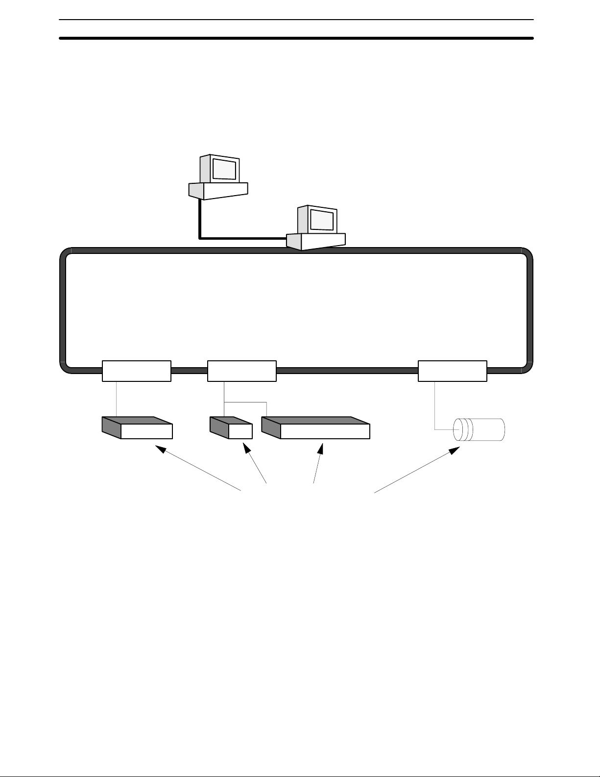
1-1 What is a Control System?
A Control System is the electronic equipment needed to control a particular process. It may include everything from a process control computer, if one is used,
to the factory computer, down through the PCs (and there may be many of them
networked together), and then on down through the network to the control components: the switches, stepping motors, solenoids, and sensors which monitor
and control the mechanical operations.
Process Control Computer
Factory Computer
PCs
PC PC PC
Control Components
A Control System can involve very large applications where many different models of PC are networked together or it could be an application as small as a single
PC controlling a single output device.
2
Page 16

The Role of the PC Section 1-2
A Position Control System
Position Control Unit Input Unit
PC
Signal line for
Servomotor
driver control
Power
source
DC Servomotor
Driver
DC Servomotor
Power
source
DC Servomotor
Driver
DC Servomotor
Handheld
Programming
Console
Control panel
Control switch
In the typical Control System example shown above, a PC controls the movement of the workpiece bed across two horizontal axes using Limit Switches and
Servomotors to monitor and control movement.
1-2 The Role of the PC
The PC is the part of the Control System that directly controls the manufacturing
process. According to the program stored in its memory, the PC accepts data
from the input devices connected to it, and uses this data to monitor the controlled system. When the program calls for some action to take place, the PC
sends data to the output devices connected to it to cause that action to take
place. The PC may be used to control a simple, repetitive task, or it may be connected to other PCs, or to a host computer in order to integrate the control of a
complex process.
3
Page 17

The Role of the PC Section 1-2
1-2-1 Input Devices
PCs can receive input from either automated or manual devices. The PC could
receive data from the user via a pushbutton switch, keyboard, or similar device.
Automated input could come from a variety of devices: micro-switches, timers,
encoders, photosensors, and so on. Some devices, like the Limit Switch shown
below, turn ON or OFF when the equipment actually makes contact with them.
Other devices, like the Photoelectric Switch and Proximity Switch shown below,
use other means, such as light or inductance, in order to get information about
the equipment being monitored.
1-2-2 Output Devices
Photoelectric Switch
Proximity Switch
Limit Switch
A PC can output to a myriad of devices for use in automated control. Almost anything that you can think of could be controlled (perhaps indirectly) by a PC. Some
of the most common devices are motors, Solenoids, Servomotors, Stepping
Motors, valves, switches, indicator lights, buzzers, and alarms. Some of these
output devices, such as the motors, Solenoids, Servomotors, Stepping Motors,
and valves, affect the controlled system directly. Others, such as the indicator
lights, buzzers, and alarms, provide output to notify personnel.
Solenoid
Stepping Motor
Servomotor
4
Page 18
How Does a PC Work? Section 1-3
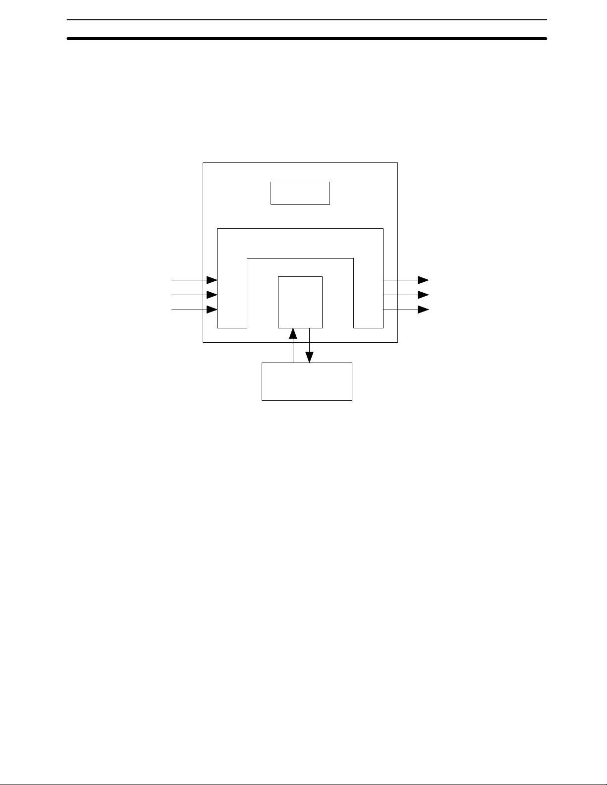
1-3 How Does a PC Work?
PCs operate by monitoring input signals and providing output signals. When
changes are detected in the signals, the PC reacts, through the user-programmed internal logic, to produce output signals. The PC continually scans the
program in its memory to achieve this control.
Block Diagram of PC
Power Supply
Memory
Signals
from
switches,
sensors,
etc.
Input Output
CPU
Programming
Device
Signals to
Solenoids,
motors,
etc.
A program for your applications must be designed, and stored in the PC. This
program is then executed as part of the cycle of internal operations of the PC.
Scanning Cycle When a PC operates, that is, when it executes its program to control an external
system, a series of operations are performed inside the PC. These internal
operations can be broadly classified into the following four categories:
1, 2, 3... 1. Common (or overseeing) processes, such as watchdog timer operation and
testing the program memory.
2. Data input and output.
3. Instruction execution.
4. Peripheral device servicing.
Cycle Time The total time required for a PC to perform all these internal operations is called
the cycle time. The flowchart and diagram on the following page illustrate these
internal operations for a typical PC.
Timing is one of the most important factors in designing a Control System. For
accurate operations, it is necessary to have answers to such questions as these:
• How long does it take for the PC to execute all the instructions in its memory?
• How long does it take for the PC to produce a control output in response to a
given input signal?
The cycle time of the PC can be automatically calculated and monitored, but it is
necessary to have an understanding of the timing relationships within the PC for
effective System design and programming.
5
Page 19

How Does a PC Work? Section 1-3
PC Operation Flowchart
Power application
Initial
Clears data areas and
resets System counters
Checks I/O Unit connection
Resets watchdog timer
Checks hardware and
program memory
processing
on
power
application
Sets error flag and
lights indicator
Error or alarm?
Error
Alarm
No
Check OK?
IR data to Output Units
Processes Remote I/O
Resets watchdog timer
Services peripheral devices
Has the applica-
tion program been completely
executed?
Resets watchdog
timer and application
program counter
Executes the program
End of Program?
No
Yes
No
Common
processes
Out
refresh
Remote
I/O
processes
Servicing
peripheral
devices
PC
cycle
time
Yes
Mathematical
Resets watchdog timer
processes
In refresh
Data from Input
Units to IR Area
6
Page 20

Available Manuals Section 1-4
1-4 Available Manuals
The following table lists other manuals that may be required to program
and/or operate the C1000H and C2000H. Operation Manuals and/or Opera-
tion Guides are also provided with individual Units and are required for wiring
and other specifications.
Name Cat. No. Contents
C1000H/C2000H Operation Manual W140 Software specifications
GPC Operation Manual W084 Programming procedures for the GPC (Graphics
Programming Console)
FIT Operation Manual W150 Programming procedures for using the FIT (Factory
Intelligent Terminal
LSS Operation Manual W237 Programming procedures for using LSS (Ladder Support
Software)
SSS Operation Manuals:
Basics W247 Introduction to programming procedures for using SSS
(SYSMAC Support Software)
C Series W248 C-series programming procedures for using SSS
(SYSMAC Support Software)
Data Access Console Operation Guide W173 Data area monitoring and data modification procedures for
the Data Access Console
Printer Interface Unit Operation Guide W107 Procedures for interfacing a PC to a printer
PROM Writer Operation Guide W155 Procedures for writing programs to EPROM chips
Floppy Disk Interface Unit Operation Guide W119 Procedures for interfacing a PC to a floppy disk drive
Wired Remote I/O System Manual W120 Information on building a Wired Remote I/O System to
enable remote I/O capability
Optical Remote I/O System Manual W136 Information on building an Optical Remote I/O System to
enable remote I/O capability
PC Link System Manual W135 Information on building a PC Link System to automatically
transfer data between PCs
Host Link System Manual W143 Information on building a Host Link System to manage
PCs from a ‘host’ computer
SYSMAC NET Link System Manual W114 Information on building a SYSMAC NET Link System and
thus create an optical LAN integrating PCs with
computers and other peripheral devices
SYSMAC LINK System Manual W174 Information on building a SYSMAC LINK System to
enable automatic data transfer, programming, and
programmed data transfer between the PCs in the System
7
Page 21

Page 22

SECTION 2
Description of All Components
This section provides information about the individual Units that make up the C1000H and the C200H Simplex and Duplex
Systems. First the names of all the parts of the three systems are given, followed by any details that apply to the Units that make
up the PC. For a description of how the Units fit together to become a PC, refer to Section 3-5 System Configurations. For
information about the model numbers of any of the parts described in this section, refer to Appendix C Standard Models.
2-1 CPU Rack 10. . . . . . . . . . . . . . . . . . . . . . . . . . . . . . . . . . . . . . . . . . . . . . . . . . . . . . . . . . . . . . .
2-2 CPU Power Supply 13. . . . . . . . . . . . . . . . . . . . . . . . . . . . . . . . . . . . . . . . . . . . . . . . . . . . . . .
2-3 I/O Backplane 15. . . . . . . . . . . . . . . . . . . . . . . . . . . . . . . . . . . . . . . . . . . . . . . . . . . . . . . . . . . .
2-4 Expansion I/O Backplane 16. . . . . . . . . . . . . . . . . . . . . . . . . . . . . . . . . . . . . . . . . . . . . . . . . . .
2-5 I/O Power Supply 16. . . . . . . . . . . . . . . . . . . . . . . . . . . . . . . . . . . . . . . . . . . . . . . . . . . . . . . . .
2-6 Duplex Unit (C2000H Duplex) 18. . . . . . . . . . . . . . . . . . . . . . . . . . . . . . . . . . . . . . . . . . . . . .
2-7 I/O Control Unit 18. . . . . . . . . . . . . . . . . . . . . . . . . . . . . . . . . . . . . . . . . . . . . . . . . . . . . . . . . .
2-8 I/O Interface Unit 18. . . . . . . . . . . . . . . . . . . . . . . . . . . . . . . . . . . . . . . . . . . . . . . . . . . . . . . . .
2-9 File Memory Unit 19. . . . . . . . . . . . . . . . . . . . . . . . . . . . . . . . . . . . . . . . . . . . . . . . . . . . . . . . .
2-10 Space Unit 19. . . . . . . . . . . . . . . . . . . . . . . . . . . . . . . . . . . . . . . . . . . . . . . . . . . . . . . . . . . . . .
2-11 I/O Remove Unit 19. . . . . . . . . . . . . . . . . . . . . . . . . . . . . . . . . . . . . . . . . . . . . . . . . . . . . . . . .
2-12 I/O Units 20. . . . . . . . . . . . . . . . . . . . . . . . . . . . . . . . . . . . . . . . . . . . . . . . . . . . . . . . . . . . . . . .
2-13 Memory Packs 23. . . . . . . . . . . . . . . . . . . . . . . . . . . . . . . . . . . . . . . . . . . . . . . . . . . . . . . . . . .
9
Page 23

CPU Rack Section 2-1
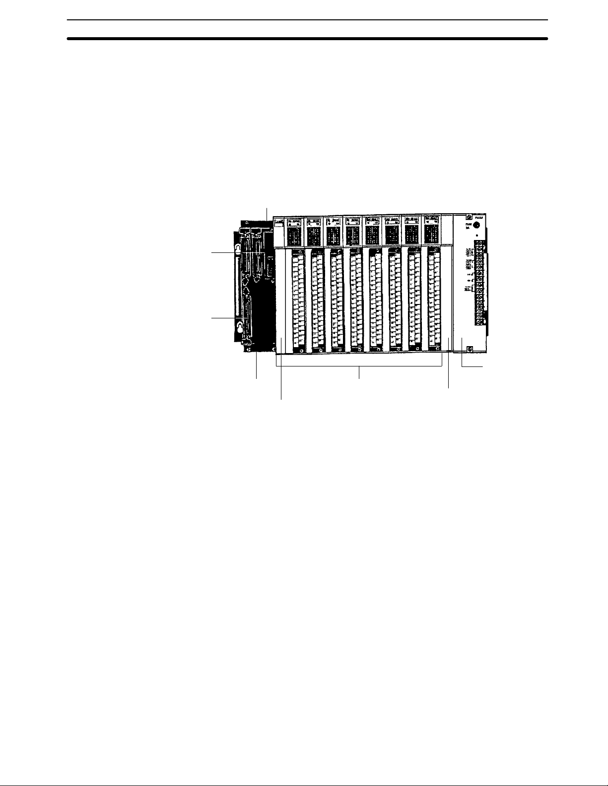
2-1 CPU Rack
The following figures show the names of all the parts of the CPU Racks used in
C1000H and C2000H Systems. Note that the Backplanes used for each system
are different.
C1000H System There are seven models of CPU Racks available for C1000H systems. Choose
a Backplane with 3, 5 (2 models), 6, 8 (2 models), or 9 I/O slots, depending on
your application. Connect the CPU Backplane to an Expansion I/O Rack via the
Expansion I/O Connector.
CPUBackplane
Expansion I/O Connector
Connects the CPU Rack to an
Expansion I/O Rack. When not
used, cover with cap.
I/O Control Unit
An I/O Control Unit must be
mounted to the Rack in order
to connect the CPU Rack to an
Expansion I/O Rack.
I/O Units
(3, 5, 6, 8, or 9 I/O Units depending
on the Backplane used)
CPU Power Supply
C2000H Simplex System The C2000H Simplex CPU Rack is different from the C1000H CPU Rack in that
there are six slots available for I/O Units rather than eight. The CPU Rack for the
Simplex and Duplex Systems have a special slot, to the left of the I/O Units, for
an I/O Remove Unit. Connect the CPU Rack to an Expansion I/O Rack via the
Expansion I/O connector. For more details concerning the Simplex System,
refer to Section 3-3 C2000H Simplex System.
CPU
I/O Remove Unit
When mounted to Rack, standard I/O Units can be
mounted or removed during
CPU operation.
Expansion I/O Connector
Connects the CPU Rack to
an Expansion I/O Rack.
When not used, cover with
cap.
10
I/O Control Unit
An I/O Control Unit must be
mounted to the Rack in order
to connect the CPU Rack to
an Expansion I/O Rack.
Backplane I/O Units (6 I/O Units) CPU Power Supply
Page 24

CPU Rack Section 2-1
C2000H Duplex System The C2000H Duplex CPU Rack is different from both the C1000H and C2000H
Simplex CPU Racks. The CPU Rack houses two CPUs and a Duplex Unit, learning no room for I/O Units. An additional Rack connected to the CPU Rack via the
Expansion I/O Connectors accommodates the I/O Units which would normally
be mounted to the CPU Rack. Note that two connecting cables are required to
connect the CPU Rack to the accompanying I/O Rack that houses the I/O Units.
Just like the Simplex System, the Duplex CPU Rack has a special slot for an I/O
Remove Unit, located on the I/O Backplane.
CPU
Expansion I/O Connectors
Connects the CPU Rack to the
I/O Rack. Use two connecting
cables.
Backplane Duplex Unit CPU Power Supply
11
Page 25

CPU Rack Section 2-1
CPU Two models of CPUs are available. One is used for C1000H Systems and the
other is used for C2000H Systems. The figure below shows the CPU that is used
with C2000H Duplex and Simplex Systems. The CPUs available for the
C1000H/C2000H Systems do not have built-in Power Supplies or Memory
Packs. Choose the Power Supply and memory pack suitable for your application.
Indicators
Peripheral device
mounting screw
Memory Pack
and Battery
Compartment
Peripheral device
connector cover
CPU mounting
screw
mounting screw
Peripheral device
connector cover
Cover storage slotPeripheral device
Peripheral Device Connector The CPU is equipped with one connector for peripheral devices. A peripheral
device, such as the CPU-Mounting Programming Console, can be mounted
directly to the CPU and does not require a connecting cable. To mount the CPUMounting Programming Console or any other peripheral device directly to the
CPU, follow these steps:
12
1, 2, 3... 1. Detach the cover of the peripheral device connector with a standard screw-
driver. Insert the detached cover into the cover storage slot provided at the
bottom of the CPU.
2. Connect the CPU-Mounting Programming Console to the peripheral device
connector.
3. To ensure a positive connection, secure the Programming Console to the
CPU by tightening the mounting screws located on the surface of the CPU.
Page 26
pp y
p
p
to240 VAC
p
CPU Power Supply Section 2-2
2-2 CPU Power Supply
The CPU Power Supply is mounted to the rightmost slot of the CPU Rack. Three
models of Power Supplies are available: 100 to 120 VAC, 200 to 240 VAC, and
24 VDC. Any one of the three models can be used in the C1000H or C2000H
Simplex Systems: however, the 3G2A5-PS221-E/PS211-E Power Supplies
cannot be used in the C2000H Duplex System. The table below summarizes the
output capacity of the three models and the current available for I/O Units
mounted on the CPU Rack.
Model Supply
3G2A5-PS221-E
3G2A5-PS223-E
3G2A5-PS211-E
Voltage
100 to 120/200
(selectable)
24 VDC
Output
Capacity
C1000H C2000H Simplex C2000H Duplex
7 A 5 VDC 4 A 3 A --- Provided
12 A 5 VDC 9 A 8 A --- Not provided
7 A 5 VDC 4 A 3 A ---
Available Current for I/O Units
24 VDC Output
Terminal
Not provided
C500-PS213-E 9 A 5 VDC 6 A 5 A ---
Note Be sure to keep the total power consumed by all the Units mounted on a Rack
within the value stated in the table above. For example, do not mount I/O Units
with a total current consumption of 5 A to a Rack supplied by a 4 A Power Supply.
As shown in the table above, the available current for I/O Units is only 5 A. For
details concerning current consumption, refer to Section 4 System Connections
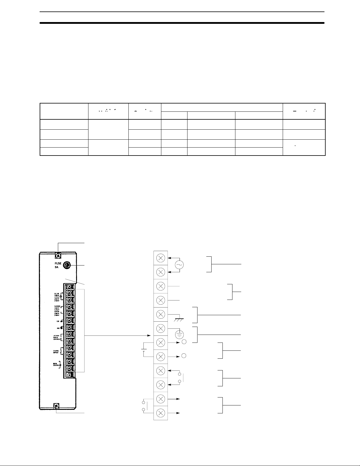
3G2A5-PS221-E This Power Supply is used in C1000H and C2000H Simplex Systems.
Mounting screw
Do not loosen this screw.
Fuse holder
Contains a MF61NR fuse
•
(3 A, 250 V, 6.35-dia. x32)
POWER indicator
Lights when power is supplied.
AC input
Voltage selector
Short: 100 to 120 V
Open: 200 to 240 V
Connect a 100 to 120 VAC or 200 to
240 VAC power source.
Short these terminals to select 100 to
120 VAC. Open them to select 200 to
240 VAC.
Ground this terminal at a resistance of
less than 100 W to improve noise
immunity or prevent electric shock.
Ground this terminal at a resistance
of less than 100 W to prevent electric
shock.
Use these terminals to supply power
to DC Input Units. Use a separate
Power Supply if the I/O Unit requires
more than 0.8 A. If a current higher
than 0.8 A is output, the PC stops.
These terminals are short-circuited as
a factory-set condition. Remove the
short-circuit bracket to start or stop
the PC with an external signal. Normally, leave them short-circuited.
These terminals are turned ON during RUN operation.
Terminals for
external connections
Mounting screw
Do not loosen this screw.
LG
GR
+
+
0.8 A, 24 VDC output
-
START input
RUN output
13
Page 27
CPU Power Supply Section 2-2
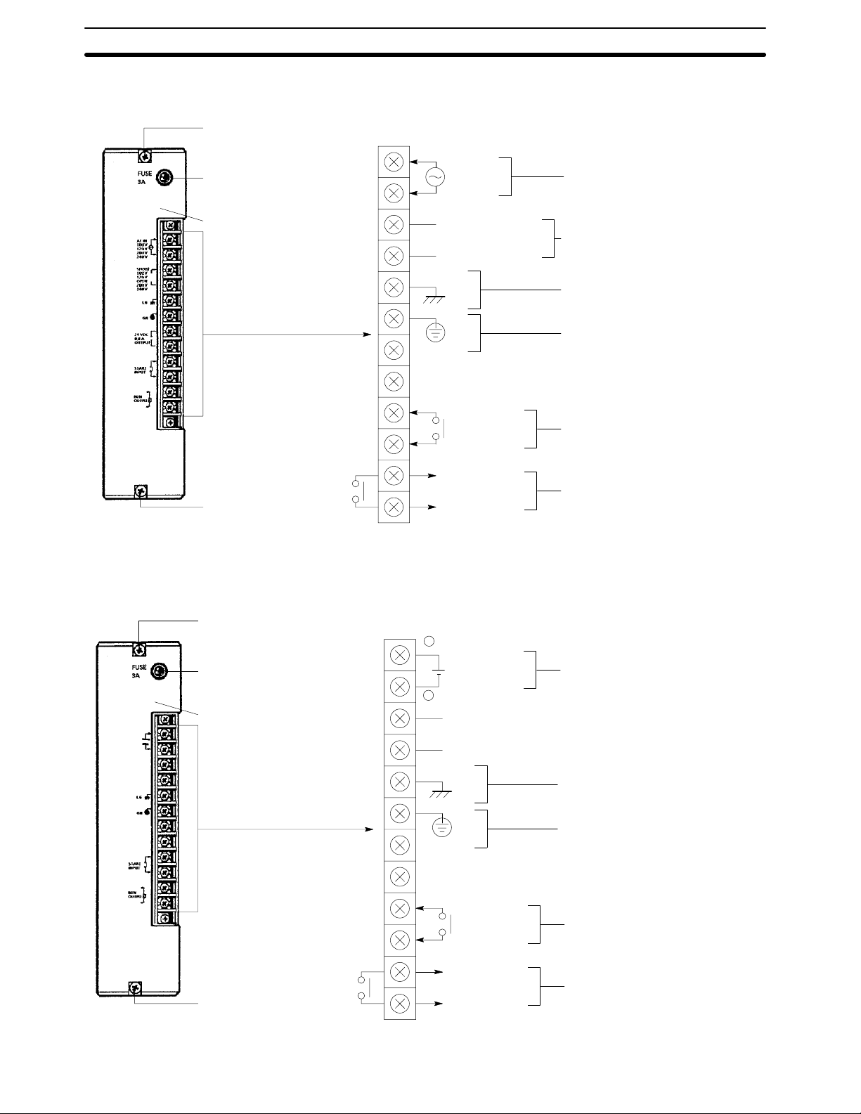
3G2A5-PS223-E This Power Supply is used in C1000H, C2000H Duplex and Simplex Systems.
Mounting screw
Do not loosen this screw.
•
3G2A5-PS211-E
C500-PS213-E
Fuse holder
Contains a MF61NR fuse
(3 A, 250 V, 6.35-dia. x32)
POWER indicator
Lights when power is supplied.
Terminals for
external connections
Mounting screw
Do not loosen this screw.
This Power Supply is used in C1000H and C2000H Simplex Systems.
AC input
Voltage selector
Short: 100 to 120 V
Open: 200 to 240 V
LG
GR
START input
RUN output
Connect a 100 to 120 VAC or 200
to 240 VAC power source.
Short these terminals to select 100
to 120 VAC. Open them to select
200 to 240 VAC.
Ground this terminal at a resistance of less than 100 W to
improve noise immunity or prevent
electric shock.
Ground this terminal at a resistance of less than 100 W to prevent
electric shock.
24 VDC output terminals are not
provided.
These terminals are short-circuited
as a factory-set condition. Remove
the short-circuit bracket to start or
stop the PC with an external signal.
Normally, leave them short-circuited.
These terminals are turned ON
during RUN operation.
Mounting screw
Do not loosen this screw.
Fuse holder
Contains a MF61NR fuse
(6.35-dia. x32)
PS211-E: 125 V, 4 A
•
PS213-E: 125 V, 6.3 A
POWER indicator
Lights when power is supplied.
Terminals for
external connections
Mounting screw
Do not loosen this screw.
+
-
24 VDC input
LG
GR
START input
RUN output
Connect a 24 VDC power source
(2.3 A min.)
Ground this terminal at a resistance
of less than 100 W to improve noise
immunity or prevent electric shock.
Ground this terminal at a resistance
of less than 100 W to prevent electric shock.
24 VDC output terminals are not
provided.
These terminals are short-circuited
as a factory-set condition. Remove
the short-circuit bracket to start or
stop the PC with an external signal.
Normally, leave them short-circuited.
These terminals are turned ON during RUN operation.
14
Page 28
I/O Backplane Section 2-3
2-3 I/O Backplane
The I/O Backplane is always paired with the CPU Rack in a C2000H Duplex system. The I/O Backplane houses the I/O Units, which cannot be mounted to the
CPU Rack. Use two cables to connect the I/O Backplane to the CPU Rack. Two
PC Link Units and one Host Link Unit can be mounted to any of the six rightmost
slots on the I/O Backplane. Similar to the C2000H CPU Backplane, the I/O Backplane also has a special slot for an I/O Remove Unit. Use one cable to connect
the I/O Remove Unit on the I/O Backplane to the I/O Remove Unit on the Expansion I/O Rack.
I/O Remove Unit
When mounted to the Rack, I/O Units can be
removed or mounted while the PC is operating.
CPU Connectors
Connects the CPU Rack to the I/O
Rack. Use two connecting cables.
Expansion I/O Backplane Connector
Connects the I/O Rack to an Expansion
I/O Rack. When not used, cover with a
cap.
I/O Units (8 Units max.)I/O Backplane
I/O Control Unit
An I/O Control Unit must be mounted to
the I/O Backplane in order to connect the
I/O Backplane to Expansion I/O Racks.
Expansion I/O
Power Supply
3G2A5-SP001 I/O Cover Unit
When mounting an I/O Cover
Unit, attach the fitting on the I/O
Backplane and the fitting on the
back of the I/O Cover Unit.
15
Page 29

I/O Power Supply Section 2-5
2-4 Expansion I/O Backplane
The Expansion I/O Backplane shown in the following diagram, can be used to
expand the C1000H and C2000H Simplex and Duplex Systems. An Expansion
I/O Rack is just like a CPU Rack, except a CPU is not mounted. However, a
Power Supply is needed for each Expansion I/O Rack. There are three models
of Expansion I/O Backplane available. The Expansion I/O Rack shown below
can only be used with C2000H Systems. This Backplane has a special slot for
the I/O Remove Unit, which allows on-line I/O Unit exchange. two models are
available for C1000H PCs, with either five or eight slots.
I/O Remove Unit
When mounted to the Rack, I/O Units can be
removed or mounted while the PC is operating.
Expansion I/O Power Supply
I/O Units
I/O Interface Unit
An I/O Interface Unit must be mounted to an Expansion
I/O Rack in order to connect the Expansion I/O Rack to
another Expansion I/O Rack.
Expansion I/O Backplane
2-5 I/O Power Supply
Just as a Power Supply must be mounted to the CPU Rack, a Power Supply
must also be mounted to the I/O Backplane and Expansion I/O Backplanes.
There are two Power Supplies available; 100 to 120/200 to 240 VAC and 24
VDC, both of which are explained below. For details, refer to Appendix B Specifi-
cations. Either Power Supply can be used in the C1000H or C2000H Simplex
Systems; however, the 24-VDC Power Supply can not be used in the C2000H
Duplex System.
Model Supply Voltage Output Capacity Available Current for I/O
Units
3G2A5-PS222-E 100 to 120/200 to 240
VAC (selectable)
3G2A5-PS212-E 24 VDC 7 A 5 VDC 6.5 A Not provided
7A 5 VDC 6.5 A Provided
24 VDC Output Terminal
16
Note Be sure to keep the total power consumed by all the Units mounted on a Rack
within the value stated in the table above. For example, do not mount I/O Units
with a total current consumption of 7A to a Rack supplied by a 7 A Power Supply.
As shown in the table above, the available current for I/O Units is only 6.5 A. For
details concerning current consumption, refer to Section 4 System Connections.
Page 30

I/O Power Supply Section 2-5
3G2A5-PS222-E
Mounting screw
Do not loosen this screw.
Fuse holder
Contains a MF61NR fuse
•
(3 A, 250 V, 6.35-dia. x32)
POWER indicator
Lights when power is supplied.
Terminals for
external connections
Mounting screw
Do not loosen this screw.
AC input
Voltage selector
Short: 100 to 120 V
Open: 200 to 240 V
LG
GR
+
0.8 A, 24 VDC output
-
Connect a 100 to 120 VAC or 200 to
240 VAC power source
Short these terminals to select 100 to
120 VAC. Open them to select 200 to
240 VAC.
Ground this terminal at a resistance
of less than 100 W to improve noise
immunity or prevent electric shock.
Ground this terminal at a resistance
of less than 100 W to prevent electric
shock.
Use these terminals to supply power
to DC Input Units. Use a separate
Power Supply if the I/O Unit operate
on more than 0.8 A. If a current higher
than 0.8 A is output, the PC stops.
These terminals are used to supply
external DC Input Units. If the Unit
requires more than 0.8 A a separate
supply must be used. The PC shuts off
automatically if a current of more than
0.8 A is drawn from the supply.
3G2A5-PS212-E
•
Mounting screw
Do not loosen this screw.
Fuse holder
Contains a MF61NR fuse
(4 A, 125 V, 6.35-dia. x32)
POWER indicator
Lights when power is supplied.
Terminals for
external connections
+
-
24 VDC input
LG
GR
Connect a 24-VDC power source
(2.3 A min.)
Ground this terminal at a resistance
of less than 100 W to improve noise
immunity or prevent electric shock.
Ground this terminal at a resistance
of less than 100 W to prevent electric
shock.
Mounting screw
Do not loosen this screw.
17
Page 31

I/O Interface Unit Section 2-8
2-6 Duplex Unit (C2000H Duplex)
The Duplex Unit shown below must be mounted to the CPU Rack in order to
operate the Duplex System. The following indicators and switches are located
on the front panel.
DUPLEX RUN (Green)
Lit during normal duplex
operation
DUPLEX BUS ERROR (Red)
Lit if an error occurs in the Duplex
System. When a DUPLEX BUS
ERROR occurs the active CPU
switches the system from a Duplex
System to a Simplex System.
VERIFY ERROR (Red)
Lit if the programs in both CPUs are
not the same. When a VERIFY
ERROR occurs, the active CPU
switches the system from a Duplex
System to a Simplex System.
ACTIVE CPU (Green)
Indicates which CPU is active.
CPU RUN (Green)
Lit when the active CPU is
operating normally.
WAITING (Green)
This indicator is lit on three different
occasions:
(1) While the program in the Duplex
System is being verified (1 to 20
seconds)
(2) When the start input is not applied
to the CPU
(3) When there is a failure in starting
the Duplex System
CPU ON/OFF switches
Use these switches to supply power to
each of the CPUs. To operate the CPU,
move the corresponding switch to the
ON position. When replacing the CPU,
move the corresponding switch to the
OFF position, and remove the CPU
from the Rack. Note that power is not
supplied to the CPU whose corresponding switch is OFF.
INITIAL SET
2-7 I/O Control Unit
An I/O Control Unit must be mounted to the CPU Rack in order to connect the
CPU Rack to an Expansion I/O Rack. In C1000H and C2000H Simplex Systems, the I/O Control Unit is mounted to the CPU Rack. In the C2000H Duplex
System, the I/O Control Unit is mounted to the I/O Rack. An I/O Control Unit can
be mounted even if no Expansion I/O Rack is used.
PROGRAM (Green)
Lit when both CPUs are in the
PROGRAM mode
CPU ERROR (Red)
Lit when an error occurs in the
CPU. Operation stops and the
RUN indicator is not lit.
MEMORY ERROR
Lit if an error is found in the PC
program
ACTIVE SYSTEM
2-8 I/O Interface Unit
An I/O Interface Unit is needed on each Expansion I/O Rack, in order to expand
the PC. If there is not an I/O Interface Unit on each Expansion I/O Rack, data
communication cannot take place. The I/O Interface Unit is mounted to the leftmost I/O position on the Expansion I/O Backplane.
18
Page 32

I/O Remove Unit Section 2-11
2-9 File Memory Unit
When a File Memory Unit is connected to the PC, contents of the Program
Memory and data areas can be transferred to and from File Memory (FM). For
details on operating the File Memory Unit, refer to the C1000H/C2000H Opera-
tion Manual.
The Unit can be mounted to either of the six rightmost slots on the Rack.
2-10 Space Unit
The Space Unit is included with the I/O Backplane to fill the space between the
Power Supply and the rightmost Unit mounted on the Backplane. This Unit only
applies to the I/O Backplane used in C2000H Duplex Systems. When mounting
this Unit be sure to remove the bracket on the Backplane first.
2-11 I/O Remove Unit
The I/O Remove Unit is unique to C2000H Systems. When mounted to a Rack of
a C2000H System, the I/O Remove Unit allows standard I/O Units to be removed
or mounted while the CPU is operating. The I/O Remove Units on each Rack are
connected by an I/O Remove Unit Connecting Cable.
In order to mount an I/O Unit to or remove an I/O Unit from any of the Racks in the
PC system, a Programming Console must be used to release the I/O Unit from
the control of the CPU. For details, refer to the PC Operation Manual.
Depending on the combination of I/O Units, a failed standard I/O Unit can be
replaced without affecting the other Units in the system.
When mounting or removing the I/O Units, the terminal block does not need to be
rewired. Simply mount the I/O Unit to the Backplane and then the terminal block
to the I/O Unit. When removing the I/O Unit, remove the terminal block first and
then remove the I/O Unit from the Backplane.
When an I/O Unit is mounted or removed while the CPU is operating on a Backplane which has an Interrupt Input Unit mounted to it, the Interrupt Input
(mounted only to C1000H and C2000H Simplex PCs) will be ignored.
Note 1. Remember that only a standard I/O Unit can be mounted or removed during
operation.
2. An I/O Remove Unit must be mounted on every Rack that will require I/O
units to be mounted or removed during operation. Even if none of the I/O
Units on the CPU Rack will be removed or mounted during operation, an I/O
Remove Unit is needed if I/O substitution is to take place on an Expansion
I/O Rack connected to the CPU Rack.
19
Page 33

I/O Units Section 2-12
Special I/O Units, such as the A/D Conversion Input Unit or the High-speed
Counter Unit, cannot be removed or mounted during operation. In addition, if
Special I/O Units and standard I/O Units are mounted on the same Rack, none of
the Units on that Rack can be removed or mounted without affecting the other
Units. However, there are combinations with other I/O Units that allow substitution during PC operation. The following table explains the instances in which
standard I/O Units, when used in combination with other I/O Units, can be
removed or mounted during PC operation. The groups defined in the table are
used only in this section and do not apply to groups of similar nature in other
manuals.
Group I/O Unit Mounted to 3G2C5-BI082 and 3G2C5-BI083 Backplane
Group A 16-/32-/64-point I/O When only Units from Group A are mounted to a Backplane the I/O Units can
be removed or mounted during PC operation.
Group B PC Link Unit
Host Link Unit
Group C A/D Conversion Unit
D/A Conversion Unit
Remote I/O Master
Remote I/O Slave
Others
When Units from Group B are mounted on the same Backplane as Units from
Group A, only the Units from Group A can be removed or mounted during PC
operation. However, this does not apply when using 3G2C5-BI083.
When Units from Group C are mounted on the same Backplane as Units from
Group A, neither Group a Units nor Group C Units can be removed or
mounted during PC operation.
Caution When removing or mounting an I/O Unit while the CPU is operating, be sure to
!
2-12 I/O Units
A-shape
remove the terminal block from the I/O Unit first and then remove the I/O Unit
from the Backplane. If the entire I/O Unit is removed from the Backplane, output
signals are not cleanly disconnected, but may be sent to external devices, causing a sudden pulse to go the external device. This may in turn cause the device to
shudder. Also, when remounting the I/O Unit to the Backplane, fir st mount the
I/O unit and then the terminal Block to the I/O Unit.
I/O Units come in 5 shapes; A-shape, B-shape, C-shape, D-shape, and
E-shape. Refer to Appendix B Specifications for the dimensions of each Unit.
Mounting screw
Provided at top and bottom
Nameplate
Fuse blowout alarm indicator
Provided on OD411/OD217/OA121/OA222
I/O indicators
Indicate ON/OFF status points
Terminal block mounting screw
Provided at top and bottom
20
20-terminal terminal block
Removable
Page 34

I/O Units Section 2-12
B-shape
Mounting screw
Provided at top and bottom
Nameplate
I/O indicators
Indicate ON/OFF status of I/O signal
Terminal block mounting screw
Provided at top and bottom
38-terminal terminal block
Removable
C-shape
Mounting screw
Provided at top and bottom
Nameplate
I/O indicators
Indicate ON/OFF status of points
Terminal block mounting screw
Provided at top and bottom
38-terminal terminal block
Removable
21
Page 35

I/O Units Section 2-12
D-shape
Mounting screw
Provided at top and bottom
Nameplate
I/O indicators
Indicate ON/OFF status of points
Two 40-terminal terminal
block connectors
Removable
E-shape
Mounting screw
Provided at top and bottom
Nameplate
I/O indicators
Indicate ON/OFF status of points
Two 24-terminal terminal block connectors
4-terminal terminal block
22
Page 36

Memory Packs Section 2-13
2-13 Memory Packs
The Memory Pack fits into the slot located on the right side of the CPU. Because
the Memory Pack is not provided with the PC upon delivery, a Memory Pack
must be selected and installed in the CPU. There are two Memory Packs available, either RAM or ROM, that can be used for both the C1000H and C2000H
Systems.
Note Mount a Memory Pack to the CPU on the left and another Memory Pack to the
CPU on the right. These Memory Packs must have the same specifications.
When using the RAM Pack, there must not be any difference in write-protect
switch settings for the left and right CPUs, otherwise a collation error will result
and the PC will not operate.
RAM Pack Data can be randomly written to and read from the RAM Pack, making it possible
to enter your own program into the CPU. However, because this is not a fixed
program, the memory of the RAM Pack is erased when power is not supplied to
the CPU or when the RAM Pack is removed from the CPU without first being connected to a backup battery.
Caution
!
1. When removing the RAM Pack from the CPU, be sure to connect the RAM
Pack to a backup battery before removing it from the CPU or the data will be
lost. Do not use the backup battery located in the compartment above the
Memory Unit Compartment. It is used to backup memory in the CPU.
2. Do not remove the battery in the CPU when the RAM Pack has been
removed from the CPU.
There is a write-protect switch and a write-protect indicator on the RAM Pack, as
shown in the following diagram. Setting the write-protect switch to OFF allows
data to be written to the RAM Pack. Use a peripheral device, such as a Programming Console, to write to the RAM Pack.
Battery connector
RAM Pack
To write data to the RAM Pack, move the write-protect switch to the OFF position. After data is written to the RAM Pack, be sure to move the write-protect
switch to the ON position to protect the data from further alterations. If you try to
write data to the Memory Pack while the write-protect switch is in the ON position, the message DISABLED ROM will appear on the Programming Console.
Four models of RAM Packs are available, which vary in memory capacity: 8K,
16K, 24K, and 32K words. Refer to Appendix C Standard Models for model numbers.
Write-protect LED indicator
Write-protect switch
OFF
ON
23
Page 37

Memory Packs Section 2-13
ROM Pack Data contained in the ROM Pack is stored on EPROM chips and cannot be
altered or erased during the CPU’s operation. The ROM Pack can accept four
EPROM chips, which can be programmed for your particular application with the
PROM Writer. The EPROM chip is mounted to the Memory Pack and the entire
pack is installed in the CPU. Once the data is written to the chip the data will not
be lost when the power to the PC is OFF.
IC Sockets
SW1 No.
Selector
RAM Pack
24
Page 38

SECTION 3
Assembly
When we speak of a PC, we usually think of it as a single object. But actually even the simplest PCs are usually composed of
several different devices. In fact a single PC can be physically spread throughout a building, but we still call it one PC.
In this section, we will start with a Backplane and use all the Units discussed in Section 2 to build a PC.
3-1 Mounting the Units 26. . . . . . . . . . . . . . . . . . . . . . . . . . . . . . . . . . . . . . . . . . . . . . . . . . . . . . . .
3-2 C2000H Duplex System 29. . . . . . . . . . . . . . . . . . . . . . . . . . . . . . . . . . . . . . . . . . . . . . . . . . . .
3-3 C2000H Simplex System 32. . . . . . . . . . . . . . . . . . . . . . . . . . . . . . . . . . . . . . . . . . . . . . . . . . .
3-4 Memory Packs 32. . . . . . . . . . . . . . . . . . . . . . . . . . . . . . . . . . . . . . . . . . . . . . . . . . . . . . . . . . .
3-5 System Configurations 34. . . . . . . . . . . . . . . . . . . . . . . . . . . . . . . . . . . . . . . . . . . . . . . . . . . . .
25
Page 39

Mounting the Units Section 3-1
3-1 Mounting the Units
There is no single Unit that can be said to constitute a Rack PC. To build a Rack
PC, we start with a Backplane. The Backplane for the C1000H/C2000H is shown
below.
C1000H/C2000H Backplane
The Backplane is a simple device having two functions. The first is to provide
physical support for the Units to be mounted to it. The second is to provide the
connectors and electrical pathways necessary for connecting the Units
mounted to it.
The first device we will add to the Backplane is a Power Supply. The Power Supply fits into the rightmost position on the Backplane and provides electricity at the
voltages required by the other Units of the PC. It can also be used to power devices other than the PC if necessary.
Power Supply
The core of the PC is the CPU. The CPU contains the program consisting of the
series of steps necessary for the control task. The CPU fits into the position directly to the left of the Power Supply.
26
CPU
Page 40

Mounting the Units Section 3-1
Unlike the CPU of the Package-type PC, the CPU of the Rack PC has no I/O
points built in. So, in order to complete this kind of PC we need to mount one or
more I/O Units to the Backplane. Mount the I/O Units to the Backplane by pressing the I/O Unit firmly into position, making sure the connectors are properly
mated. Secure the Unit by tightening the mounting screws located on the top and
bottom of the Unit.
Mounting screws
Provided at the top and
bottom of the Unit
Connector
Make sure the connectors
are properly mated.
The figure below shows one I/O Unit mounted directly to the left slot of the CPU
Rack.
I/O Unit
I/O Units are where the control connections are made from the PC to all the various input devices and output devices. As you can see from the figure, there is
still some space available on the right side of the I/O Unit. This space is for any
additional I/O Units that may be required.
27
Page 41

Mounting the Units Section 3-1
The figure above shows a total of six I/O Units mounted to the Backplane. Backplanes are available in different lengths, and can hold a different number of I/O
Units accordingly. Of course, not all I/O Units look exactly alike, but the ones in
the figure show their typical appearance. This configuration of Backplane,
Power Supply, CPU, and I/O Units is called a CPU Rack. This term refers to the
Backplane and all the Units mounted to it. However, if we want to include more
than six I/O Units in our configuration we can add an additional Backplane. First,
though, we have to mount an I/O Control Unit to the leftmost slot of the CPU
Rack.
I/O Control Unit
Now we can use a cable to connect the CPU Rack to another Backplane. This
Backplane has a Power Supply and I/O Units mounted to it, but it has no CPU of
its own. The additional Backplane must also have an I/O Interface Unit mounted
to its leftmost position. This configuration of additional Backplane, Power Supply, I/O Units, and I/O Interface Unit is called an Expansion I/O Rack.
CPU Rack
Expansion I/O Rack
28
I/O Interface Unit
The CPU Rack and Expansion I/O Rack shown above are connected by a cable.
Remember that this whole configuration is still referred to as one PC. It is possible to keep adding Expansion I/O Racks in this way until the maximum number of
I/O points for the system is reached. Each Expansion I/O Rack needs an I/O Interface Unit.
Page 42

C2000H Duplex System Section 3-2
3-2 C2000H Duplex System
The C2000H has a unique feature. The C2000H lets you build a PC that uses
two CPUs. This is called a Duplex System. Either CPU, which is mounted to the
CPU Rack, is capable of assuming the system function. One CPU controls the
system while the other CPU assumes a standby status. Consequently, if a failure
occurs in one of the CPUs, the other CPU can take over the system function,
preventing the entire system from halting, The figure below shows a Duplex System. Note that the CPU Rack is connected to the I/O Rack by two cables.
CPUs
CPU Rack
Duplex Unit
I/O Rack
While the Duplex System is in operation, one of the two CPUs has “active” status
and the other CPU has “standby” status. The active CPU executes the program
and controls the I/O Units while the standby CPU merely executes the program,
but does not control the I/O Units. The status of the CPUs can be determined by
setting the selector switch on the front panel of the Duplex Unit.
If an error occurs in the active CPU, making further operation impossible, the
standby CPU automatically becomes active and takes over operation. The
failed CPU can be repaired or replaced without having to shut down the entire
CPU.
Operating Mode The operating mode is set through the active CPU. Once the operating mode of
the active CPU is set, the standby CPU is automatically set in same operating
mode as the active CPU.
Peripheral Devices As mentioned, the operating mode can only be set through the active CPU. How-
ever, peripheral devices such as the Programming Console can be mounted to
the standby CPU to monitor operations.
Initial Settings Take the following steps to prepare the Duplex System for operation.
1, 2, 3... 1. Be sure to install identical Memory Packs in both CPUs. Because one of the
CPUs in the Duplex System acts as a standby system, make sure that identical Memory Packs are installed in both CPUs. IF the active CPU can no
longer control the system, the standby CPU can take over the System using
an identical program.
ROM Packs When using ROM Packs, make sure that the same number and
same type of EPROM chips are mounted to both ROM Packs. In addition,
the same program must be written to both ROM Packs.
RAM Packs When using RAM Packs, make sure the Units have the same
memory capacity. Write the program to the RAM Unit installed in the active
CPU. The program written to the active CPU is automatically written to the
memory of the standby CPU when the Duplex System is put into operation.
29
Page 43

C2000H Duplex System Section 3-2
Note All information previously stored in the RAM Pack of the standby CPU
will be erased when a new program is written to the RAM Pack of the
active CPU.
2. Set the System Switch, located on the front panel of the Duplex Unit, to DPL
(Duplex System) or SPL (Simplex System). As shown below, the switch is
set to DPL to indicate a Duplex System.
CPU ON/OFF switches
Use these switches to supply power to
each of the CPUs. To operate the CPU,
move the corresponding switch to the
ON position. When replacing the CPU,
move the corresponding switch to the
OFF position, and remove the CPU
from the Rack. Note that power is not
supplied to the CPU whose corresponding switch is OFF.
ACTIVE SYSTEM
DPL (Duplex)
SPL (Simplex)
INITIAL SET
3. Next, select the active CPU by setting the Active Switch to RIGHT or LEFT.
In the example above, the right CPU is the active CPU.
4. To complete the initial settings, set both CPU ON/OFF selectors on the front
panel of the Duplex Unit to the ON position. If both CPU selectors are not in
the ON position, the Duplex System cannot operate.
When an Error Occurs in
the Duplex System
30
When the Duplex System is put into operation, both CPUs are in the ON position
and an active CPU, either the right CPU or the left CPU, is selected. A Duplex
System is a control system with two operable CPUs, an active CPU and a standby CPU, either of which can take over system operation at any time. However, if
an error occurs causing one of the CPUs to fail, the system automatically
changes to a Simplex System, regardless of the switch settings on the front panel of the Duplex Unit. For example, if an error occurs in the standby CPU causing
Page 44

C2000H Duplex System Section 3-2
it to be inoperable, it can no longer be a Duplex System and therefore automatically changes to a Simplex System, with only the active CPU controlling the system.
If there is an error that causes the active CPU to fail, the system again automatically changes to a Simplex System, switching control to the operable CPU (the
standby CPU). For example, the switches on the front panel of the Duplex Unit
indicate that the right CPU is active and controlling the I/O Units in a Duplex System. If the active CPU fails, the system changes from a Duplex System to a Simplex System and the operable standby CPU (in this example, the left CPU) takes
over the system operation and becomes the active CPU. The change from Duplex to Simplex and from active CPU to standby CPU takes place regardless of
the settings on the front panel of the Duplex Unit.
Switching from Duplex to
Simplex
Select the active CPU and set the ACTIVE switch to LEFT or RIGHT depending on which CPU is to be active.
Set the CPU ON/OFF switch which corresponds to the active CPU to the ON
position.
The SYSTEM switch is
set to SPL for Simplex
If you are using a Duplex System but want to use only one CPU to write a program to the memory of the CPU or test the program in the CPU, switch the Duplex System to a Simplex System.
The flow chart below illustrates how the Duplex System can be changed to Simplex operation. The switches referred to in the flow chart are on the front panel of
the Duplex Unit. Assume that there is a Programming Console already mounted
to the active CPU.
The SYSTEM switch is
set to DPL for Duplex
Supple power
Supple power
Set the SYSTEM
switch to SPL
Press INITIAL SET Move the MODE SELEC-
Simplex System operation begins
Enter password
TOR switch on the Programming Console from
RUN/MONITOR to PROGRAM and then back to
RUN/MONITOR.
31
Page 45

Memory Packs Section 3-4
3-3 C2000H Simplex System
The C2000H Simplex System is a PC that operates with only one CPU. The operation of the Simplex System is quite similar to that of the C1000H, in that a
maximum of seven Expansion I/O Racks can be utilized to access a maximum of
2,048 I/O points.
One difference can be seen in the CPU Rack. Only six I/O Units can be mounted
to the CPU Rack of the C2000H Simplex System. Also, an I/O Remove Unit, a
feature unique to the C2000H Systems, can be mounted to the CPU and Expansion I/O Racks to allow on-line exchange.
3-4 Memory Packs
The CPU has a removable Memory Pack that stores the user program. Two
Memory Packs are available, in either RAM or ROM. You can write your own program into the RAM Pack or you can copy a program that has already been written to an EPROM chip and mount it in the ROM Pack. The EPROM Chip must be
mounted to the PROM Writer in order for the program to be written to it. Then the
EPROM Chip must be mounted to the ROM Pack.
Mounting the EPROM Chip
to the ROM Pack
Switch Setting IC Socket
SW1 No. Selection CHIP 0 CHIP 1 CHIP 2 CHIP 3
16K words 2 Two 27128 ---
32K words 4 Two 27128 Two 27128
5 Two 27256 (see note) ---
6 Two 27512 ---
Depending on the memory required for your application, choose either two chips
for 16K words or four chips for 32K words. Only one model of EPROM chip can
be used in the C1000H and C2000H PCs. Refer to Appendix B Specifications for
specifications of the EPROM chips.
Using the diagram and the table below as a reference, mount the EPROM chips
to the correct IC sockets.
Use a standard
screwdriver to set
the SW1 switch for
either 16K words or
32K words.
The table below summarizes the programming capacity.
Up to 16K words 16K to 32K words
Upper 8 Bits Lower 8 Bits Upper 8 Bits Lower 8 Bits
32
Note EPROM 27256 has to be 150 ns.
Page 46

Memory Packs Section 3-4
How to Install the Memory
Pack
1, 2, 3... 1. Turn the power to the PC OFF.
Caution Do not attempt to install the Memory Pack in the CPU while the power to the PC
!
Take the following steps to install the Memory Pack in the CPU.
is ON. Doing so may cause data to be lost, or may damage the CPU or Memory
Pack.
2. Using a standard screwdriver, remove the Memory Pack compartment
cover located on the front panel of the CPU. Push in the latch on the cover
and slide the cover upward.
Use a standard screwdriver to remove the Memory
Pack compartment cover.
3. When using the RAM Pack, make sure the write-protect switch is set before
installing the Unit in the CPU. Refer to the following table for the status of the
write-protect function.
Write enabled Write disabled
Write-protect switch OFF ON
Write-protect LED indicator Unlit Lit
4. Insert the Memory Pack (component side facing left) into the Memory compartment. When the Unit is almost completely inserted into the CPU, there
may be a slight resistance as the Memory Pack connector mates with the
connector inside the CPU. Continue pushing on the Memory Pack until it is
inserted completely into the CPU.
Memory Unit guide
Memory Pack
(ROM or RAM
Pack)
Memory Unit holding brackets
Mounting screws for Memory
Unit holding bracket
5. Reattach the memory compartment cover.
33
Page 47

System Configurations Section 3-5
How to Remove the
Memory Pack
Follow the steps below to remove the Memory Pack from the CPU.
1, 2, 3... 1. Turn the power to the PC OFF.
2. Using a standard screwdriver, remove the Memory Pack compartment
cover located on the front panel of the CPU. Push in the latch on the cover
and slide the cover upward.
3. When removing the RAM Pack from the CPU, be sure to connect the RAM
Pack to a back-up battery before removing it from the Memory Compartment, or the data will be lost.
Note Do not use the back-up battery located in the compartment above the
Memory Unit. This battery is used to back-up the internal memory of
the CPU. If this battery is disconnected, the contents of the internal
memory will be lost.
4. Pull the white tabs of the Memory Pack up and out. The tabs push against
the guide rail provided for the Memory Pack and force the Memory Pack out
of the Memory Pack compartment.
Note When moving the C1000H or C2000H PCs, secure the Memory Pack
with holding brackets.
3-5 System Configurations
This section provides illustrations of assembled C1000H and C2000H Systems.
C1000H System The following figure shows an assembled C1000H CPU Rack and one Expan-
sion I/O Rack. When 7 Expansion I/O Racks are connected to a CPU Rack, a
maximum of 1,024 I/O points are available. When Remote I/O Units are used in
the system, the maximum number of I/O points available increases to 2,048.
CPU
CPU
Power Supply
I/O Control Unit
CPU Rack
Connecting Cable
I/O Interface Unit
Programming
Console
Expansion I/O
Power Supply
C2000H Simplex System The C2000H Simplex System is similar to the C1000H except that the C2000H
Simplex CPU Rack has a maximum of six slots instead of eight. When seven
Expansion I/O Racks are connected to a CPU Rack, a maximum number of
34
Page 48

System Configurations Section 3-5
2,048 points are available, regardless of whether Remote I/O Units are used in
the system.
CPU
I/O Remove Unit
I/O Control Unit
Connecting Cable
I/O Interface Unit
Connecting Cable for I/O Remove Unit
CPU
Power Supply
CPU Rack
(C2000H Simplex System)
Programming Console
Expansion I/O
Power Supply
Expansion I/O Racks
A maximum of seven
Expansion I/O Racks
can be connected to
the CPU Rack.
C2000H Duplex System The CPU Rack for the C2000H Duplex System, unlike the C1000H and the
C2000H Simplex Systems, has two CPUs and a Duplex Unit mounted to it. The
C2000H Duplex System is configured differently from the Simplex System, because it has an additional I/O Rack connected to the CPU Rack to accommodate
the I/O Units. Note that there are two connecting cables that connect the CPU
Rack to the I/O Rack. A maximum of seven Expansion I/O Racks can be connected to the I/O Rack, making 1,024 the maximum number of points available
when 16-point I/O Units are used. The number of I/O points is increased to 2,048
when the system is configured with 32-point I/O Units.
Duplex Unit
Monitors and controls the
CPUs
CPU
CPU
CPU Power Supply
CPU Rack (Duplex System)
I/O Remove Unit
Necessary in order to remove
or mount standard I/O Units
during CPU operation.
I/O Control Unit
Necessary in order to expand
the CPU Rack
I/O Remove Unit
Necessary in order to remove
or mount standard I/O Units
during CPU operation.
I/O Interface Unit
Must be mounted to each Expansion I/O Rack
Programming Console
Connecting Cable
Expansion I/O Power Supply
Must be mounted to each Expansion I/O Rack.
I/O Rack (used only for Duplex System)
Connecting Cable for I/O Remove Unit
Expansion I/O Power Supply
Must be mounted to each Expansion I/O Rack.
Expansion I/O Rack
A maximum of seven Expansion I/O
Racks can be connected to the CPU
and I/O Racks
35
Page 49

System Configurations Section 3-5
Where I/O Units Can be
Mounted
Special I/O
Units
Host Link
Units
I/O Units Standard I/O Units are available with 16, 32, or 64 points. These Units can be mounted to or removed
Memory Packs RAM or ROM Packs are available. The ROM Pack requires a separately available EPROM chip.
Remote I/O
Master Unit
The number of Special I/O Units that can be used depends upon the number of points available and
the number of points the Special I/O Unit requires. Be sure to check the current capacity for each I/O
Unit and the CPU.
When using 3G2A5-LK103(-P)/LK203 Host Link Units, a maximum of two Rack-mounting Host Link
Units can be mounted to the CPU Rack or I/O Rack. An additional CPU-mounting Host Link Unit can
be mounted to the CPU, making the total number of Host Link Units three.
When using 3G2A5-LK101-(P)EV1/LK201-EV1 Host Link Units, only one Rack-mounting Host Link
Unit can be mounted to the CPU Rack or I/O Rack. An additional CPU-mounting Host Link Unit can
be mounted to the CPU, making the total number of Host Link Units two.
These Host Link Units cannot be mounted on Expansion I/O Rack.
If the SYSMAC Net Link Unit is mounted, either 3G2A5-LK103(-P) or 3G2A5-LK203 can be mounted
as Rack-mounting Host Link Unit. Both models cannot be mounted at the same time.
from the Rack if there is an I/O Remove Unit mounted to the Rack. Refer to Section 2 Description of
All Components for details.
Install identical Memory Packs in both CPUs, if you are using a C2000H Duplex PC.
Up to eight Remote I/O Master Units can be mounted to both the I/O Rack and the Expansion I/O
Racks. When the Remote I/O Unit is mounted to a Rack, a Rack number must be set so that the CPU
can identify the Remote I/O Unit. Mount the Remote I/O Slave Unit to the leftmost position (the I/O
Interface Unit position) on the Slave Rack. For details, refer to the C1000H/C2000H Operation
Manual.
The table below summarizes the Units that can be used in the systems described in this manual.
The table below summarizes specific Units that can and cannot be mounted in
the CPU and Expansion Racks and the number that can be used in each PC. For
detailed information about the Units listed below, refer to the Operation Manual
for the individual Unit.
Unit C1000H and C2000H Simplex C2000H Duplex
CPU Rack Expansion I/O Rack I/O Rack Expansion I/O Rack
16-, 32-, 64-point I/O YES YES YES YES
Interrupt Input YES (4 max.) NO NO NO
Special I/O YES YES YES YES
I/O Link YES YES YES YES
PC Link YES (2 max.) NO YES (2 max.) NO
Host Link (see note 1) YES
SYSMAC Link YES
SYSMAC Net Link YES NO YES NO
File memory YES (1 max.) NO YES NO
Remote I/O Master YES YES YES YES
Remote I/O Slave NO YES NO YES
Total: 2
max.
NO YES
NO NO
Total: 2
max.
NO
NO
Note 1. A CPU-mounting Host Link Unit can be mounted, in addition to the Rack-
mounting Host Link Unit.
2. The Position Control Unit (3G2A5-NC103-E) and the PID Unit each require
two I/O slots on the CPU Rack and the Expansion I/O Racks
36
3. The following Units can only be mounted to one of the three or five rightmost
slots on the CPU Backplane, depending on which Backplane is used.
PC Link
Host Link
SYSMAC Net Link
File Memory
SYSMAC Link
Page 50

System Configurations Section 3-5
4. When two or more PCs are linked by the PC Link Unit, a maximum of 32 PC
Link Units can be used (linking 31 PCs), in any number of subsystems.
5. When mounting two Host Link, SYSMAC Link, or SYSMAC Net Link Units to
a C200H PC, use CPU01-EV1.
37
Page 51

Page 52

SECTION 4
System Connections
In the preceding sections we have covered all the parts of a PC and how they should be assembled. This section provides
detailed information on PC connections.
4-1 Current Consumption 40. . . . . . . . . . . . . . . . . . . . . . . . . . . . . . . . . . . . . . . . . . . . . . . . . . . . . .
4-2 I/O Connections 43. . . . . . . . . . . . . . . . . . . . . . . . . . . . . . . . . . . . . . . . . . . . . . . . . . . . . . . . . .
39
Page 53

pp y
pp y
Current Consumption Section 4-1
4-1 Current Consumption
The Power Supplies are limited in the total current they can supply to I/O Units.
The following table shows the maximum currents allowed.
Power Supplies
CPU Power Supply
(C1000H)
CPU Power Supply
(C2000H Simplex)
I/O Power Supply 3G2A5-PS222-E 7 A 5 VDC 6.5 A
Note Do not exceed the maximum current ratings for each of the voltages supplied by
any single Unit listed above. In addition, do not exceed the total maximum power
output for any single Unit listed above. Refer to the tables on the following page
for the current consumption of individual I/O Units.
Unit Model Output Capacity Current Available
for I/O Units
3G2A5-PS221-E 7 A 5 VDC 4 A
C500-PS213-E 9 A 5 VDC 6 A
3G2A5-PS223-E 12 A 5 VDC 9 A
3G2A5-PS211-E 7 A 5 VDC 4 A
3G2A5-PS221-E 7 A 5 VDC 3 A
C500-PS213-E 9 A 5 VDC 5 A
3G2A5-PS223-E 12 A 5 VDC 8 A
3G2A5-PS211-E 7 A 5 VDC 3 A
3G2A5-PS212-E
Input Units
Unit Model Current Consumption
(A)
DC Input 3G2A5-ID112 0.01
C500-ID114 0.34
3G2A5-ID213 0.02
3G2A5-ID215 0.16
3G2A5-ID218 0.26
C500-ID218CN 0.2
3G2A5-ID212 0.3
3G2A5-ID219 0.34
Interrupt Input Unit
(see note)
AC Input 3G2A5-IA121 0.18
TTL Input C500-ID501CN 0.2
AC/DC Input 3G2A5-IM211 0.01
C2000-ID216 0.1
3G2A5-IA222 0.18
C500-IA223 0.18
3G2A5-IA122 0.18
3G2A5-IM212 0.2
Note The Interrupt Input Unit is used only in C1000H and C2000H Simplex Systems.
40
Page 54

Current Consumption Section 4-1
Output Units
Unit Model Current Consumption
Contact Output 3G2A5-OC221 0.1
3G2A5-OC223 0.1
3G2A5-OC224-E 0.2
Transistor Output 3G2A5-OD411 0.16
3G2A5-OD215 0.2
3G2A5-OD412 0.23
3G2A5-OD414 0.23
3G2A5-OD212 0.23
3G2A5-OD211 0.3
3G2A5-OD213 0.46
3G2A5-OD217 0.16
C500-OD218 0.23
C500-OD219 0.16
3G2A5-OD415CN 0.23
Triac Output 3G2A5-OA121 0.3
3G2A5-OA222 0.3
3G2A5-OA223 0.45
C500-OA225 0.2
C500-OA226 0.45
TTL Output C500-OD501CN 0.25
DC Input/Transistor
Output Unit
Dummy I/O 3G2A5-DUM01 0.035
C500-MD211CN 0.26
(A)
41
Page 55

Current Consumption Section 4-1
Special I/O Units
Unit Model Current Consumption
(A)
A/D Converter Input 3G2A5-AD001 to -AD005 0.3 each
3G2A5-AD006 0.75 each
3G2A5-AD007
C500-AD101 0.88
C500-AD501 1.2
D/A Converter Output 3G2A5-DA001 to -DA005 0.55 each
C500-DA101 1.3
C500-DA103 1.3
High-speed Counter 3G2A5-CT001 0.3
3G2A5-CT012 0.55
C500-CT021 0.35
C500-CT041 1.0
Magnetic Card Reader 3G2A5-MGC01-E 1.0
PID 3G2A5-PID01-E 1.4
Position Control 3G2A5-NC103-E Total 1.4
3G2A5-TU001-E
3G2A5-NC111-EV1 Total 1.0
3G2A5-TU001-E
3G2A5-NC222-E Total 1.3
3G2A5-TU002-E
ASCII C500-ASC04 0.5
ID Sensor C500-IDS01-V2/02-V1 0.4 each
C500-IDS21/22
Ladder Program I/O 3G2A5-LDP01-V2 0.8
File Memory C1000H-FMR11 0.35 each
C1000H-FMR21
Cam Positioner C500-CP131 0.35
Link Units and Remote I/O
Units
Note The SYSMAC Link Unit is used only in C1000H and C2000H Simplex Systems.
42
Unit Model Current Consumption
(A)
I/O Link 3G2A5-LK010-(P)E 0.6
PC Link C500-LK009-V1 0.9
Host Link C500-LK103 (-P) 1.0 each
C500-LK203
Remote I/O Master 3G2A5-RM001-(P)EV1 0.7
Remote I/O Slave 3G2A5-RT001-(P)EV1 0.5 each
3G2A5-RT002-(P)EV1
SYSMAC Net Link C500-SNT31-V4 1.4
SYSMAC Link (see note) C1000H-SLK11 0.8 each
C1000H-SLK21-V1
Wired Remote I/O Master C500-RM201 0.3
Wired Remote I/O Slave C500-RT201 0.5
Page 56

I/O Connections Section 4-2
4-2 I/O Connections
Connect the I/O Devices to the I/O Units using AWG (cross-sectional area:
2
0.3 mm
tional area: 0.3 to 0.75 mm
) for 19-terminal terminal blocks and AWG 22 to lead wire (cross-sec-
2
) for 10-terminal terminal blocks. The terminals have
screws with 3.5-mm diameter heads and self-raising pressure plates. Connect
the lead wires to the terminals as shown. Tighten the screws to a torque of 0.8
NSm.
Use ring crimp terminals for wiring. Do not connect bare stranded wires directly
to terminal blocks.
7 mm max.7 mm max.
Terminal Block The terminal block of an I/O Unit can be removed by loosening the mounting
screws. You do not have to remove the lead wires from the terminal block in order to remove it from an I/O Unit.
Note Putting I/O Lines and high-tension lines or power lines in the same duct or con-
duit may cause the I/O Lines to be affected by noise. This may cause a malfunction in the I/O Unit or may cause damage to the I/O Unit or I/O devices.
Terminal block mounting screws
Loosen the terminal block mounting screws to remove
the terminal block from the I/O Unit. Make sure the
mounting screws on the terminal block are tightened after wiring is complete, and the terminal block is remounted to the I/O Unit.
Note When a Triac Output Unit is used to drive a low-current load, the load may not
turn completely OFF due to a leakage current. To compensate for the leakage
current, connect a bleeder resistor in parallel with the load.
43
Page 57

I/O Connections Section 4-2
Wiring Examples The following are examples of how to connect I/O devices to I/O Units. During
wiring, work slowly and carefully. If an input device is connected to an Output
Unit, damage may result. Check all I/O devices to make sure they meet the
specifications (refer to Appendix B Specifications). Be sure to allow for leakage
current and load inductance.
DC Input Units
Contact output
IN DC input
COM
When using the following configurations, the sensor and Input Unit should receive their power from the same supply.
NPN current output
+
Current
regulator
Output
7 mA
0 V
IN DC input
COM
NPN open-collector output
+
Output
7 mA
0 V
PNP current output
+
Output
7 mA
0 V
Sensor
Power
Supply
IN DC input
COM
Sensor
Power
Supply
IN AC/DC input
COM
44
Page 58

I/O Connections Section 4-2
AC Input
Contact output
IN AC input
COM
AC Switching
IN AC input
Prox.
switch
main
circuit
Note If a reed switch is used as the input contact of the AC Input Unit, the reed switch
must have a permissible current capacity of 1 A minimum, otherwise contact
weld may result due to inrush current.
COM
Output Units A fuse placed in the output circuit will protect the output element, circuit board,
etc., in the event of a short circuit in the output circuit.
OUT
COM
Relay,
solenoid, etc.
+
45
Page 59

Page 60

SECTION 5
Installation Environment
This section details the necessary environment and conditions for installation of the PC. For specific instructions on mounting
Units and wiring for I/O and power, refer to Section 3-5 System Configurations and 4-2 I/O Connections.
Caution Static electricity can cause damage to PC components. Your body can carry an
!
electrostatic charge, especially when the humidity is low. Before touching the PC
be sure to first touch a grounded metallic object, such as a water pipe, in order to
discharge any static build-up.
5-1 Cooling 48. . . . . . . . . . . . . . . . . . . . . . . . . . . . . . . . . . . . . . . . . . . . . . . . . . . . . . . . . . . . . . . . .
5-2 Mounting Requirements 48. . . . . . . . . . . . . . . . . . . . . . . . . . . . . . . . . . . . . . . . . . . . . . . . . . . .
5-3 Duct Work 50. . . . . . . . . . . . . . . . . . . . . . . . . . . . . . . . . . . . . . . . . . . . . . . . . . . . . . . . . . . . . .
5-4 Preventing Noise 51. . . . . . . . . . . . . . . . . . . . . . . . . . . . . . . . . . . . . . . . . . . . . . . . . . . . . . . . .
47
Page 61

Mounting Requirements Section 5-2
5-1 Cooling
There are two points to consider in order to ensure that the PC does not overheat. The first is the clearance between the Racks, and the second is installation
of a cooling fan.
Clearance Between Racks The Racks need to have sufficient room between each other to allow for I/O wir-
ing, and additional room to ensure that the I/O wiring does not hamper cooling.
However, the Racks must be mounted so that the length of the connecting cable
does not exceed 2 m, and the total length of the Connecting Cables between all
Racks does not exceed 12 m. For details about cable lengths, refer to Appendix
C Standard Models. As a general rule, about 70 to 120 mm should be left between any two Racks (50 to 100 mm should be left between any two Racks in the
Duplex System).
Cooling Fan A cooling fan is not always necessary, but may be needed in some installations.
Try to avoid mounting the PC in a warm area, or over a source of heat. A cooling
fan is needed if the ambient temperature may become higher than that specified
(refer to Appendix B Specifications). If the PC is mounted in an enclosure install
a cooling fan, as shown in the following diagram, to maintain the ambient temperature within specifications.
PC
Louver
5-2 Mounting Requirements
The PC consists of from one to eight Racks, or from one to nine Racks if you are
using the C2000H Duplex System. Each Rack must be mounted vertically, that
is with the printing on the front panels oriented as it would normally read. The
Racks should be mounted one above the other with the CPU Rack uppermost.
Fan
48
The PC may be directly mounted to any sturdy support meeting the environmental specifications (refer to Appendix B Specifications).
The duct work shown in the following diagram is not used for mounting the
Racks. Although optional, the duct work can be used to house the wires from the
I/O Units that run along the sides of the Racks, keeping the wires from becoming
entangled with other machines. The figures illustrate the correct way to mount
the Racks.
Page 62

Mounting Requirements Section 5-2
C1000H System
CPU Rack
Expansion I/O Rack
C2000H Duplex
CPU Rack
I/O Backplane
(for C2000H
Duplex only)
49
Page 63

Duct Work Section 5-3
The following figure shows a side view of a mounted CPU and two Expansion I/O
Racks. There should be a distance of 70 to 120 mm between the mounted Units.
CPU
Duct
70 to 120 mm
I/O
Duct
70 to 120 mm
I/O
Approx. 100 mm
5-3 Duct Work
If power cables carrying more than 10 A 400 V, or 20 A 220 V must be run alongside the I/O wiring (that is, parallel to it), leave at least 300 mm between the
power cables and the I/O wiring as shown below.
Low current cable
1
Control cable
2
300 mm min.
300 mm min.
Power cable
3
Grounding at resistance
of less than 100 W
1 = I/O wiring
2 = General control wiring
3 = Power cables
50
Page 64

Preventing Noise Section 5-4
If the I/O wiring and power cables must be placed in the same duct (for example,
where they are connected to the equipment), shield them from each other using
grounded metal plates.
Metal plate (iron)
200 mm min.
123
Grounding at resistance
of less than 100 W
1 = I/O wiring
2 = General control wiring
3 = Power cables
5-4 Preventing Noise
In order to prevent noise from interfering with the operation of the PC, use AWG
2
14 twisted-pair cables (cross-sectional area: 2 mm
min.). Avoid mounting the
PC close to high-power equipment, and make sure the point of installation is at
least 200 mm away from power cables as shown below.
Power lines
200 mm min.
PC
200 mm min.
Whenever possible, use wiring conduit to hold the I/O wiring. Standard wiring
conduit should be used, and it should be long enough to completely contain the
I/O wiring and keep it separated from other cables.
51
Page 65

Page 66

SECTION 6
Power Considerations
Use a commercially available 100 to 120 VAC, 200 to 240 VAC, or 24 VDC power source, according to the model of PC you
are using (refer to Appendix B Specifications). Expansion I/O Racks, if used, must also be connected to the power source. If
possible, use independent power sources for the PC, input devices, and output devices. All Racks of the PC may be connected
to one power source.
53
Page 67

Power Considerations Section 6
Grounding The Line Ground (LG) terminal is a noise-filtered neutral terminal that does not
normally require grounding. If electrical noise is a problem, however, this terminal should be connected to the Ground (GR) terminal.
To avoid electrical shock, attach a grounded (earth ground) AWG 14 wire (crosssectional area: 2 mm
be less than 100 W. Do not use a wire longer than 20 m. Care must be taken,
because ground resistance is affected by environmental conditions such as soil
composition, water content, time of year, and the length of time since the wire
was laid underground.
PC operation may be adversely affected if the ground wire is shared with other
equipment, or if the ground wire is attached to the metal structure of a building.
When using an Expansion I/O Rack, the Rack must also be grounded to the GR
terminal. The same ground can be used for all connections.
Power Failure A sequential circuit is built into the PC to handle power interruptions. This circuit
prevents malfunctions due to momentary power loss or voltage drops. A timing
diagram for the operation of this circuit is shown below.
OFF ON
Power Supply
Power failure
detection signal
2
min.) to the GR terminal. The resistance to ground must
Momentary power
failure detection time
CPU voltage (5 V)
Power reset
Approx. 1 s
Run monitor outputs
The PC ignores all momentary power failures if the interruption lasts no longer
than 10 ms. If the interruption lasts between 10 and 25 ms, the interruption may
or may not be detected. If the supply voltage drops below 85% of the rated voltage for longer that 25 ms (less for the DC Power Supply), the PC will stop operating and the external outputs will be automatically turned OFF. Operation is resumed automatically when the voltage is restored to more than 85% of the rated
value.
Wiring The following diagrams show the proper way to connect the power source to the
PC. The terminals marked “NC” are not connected internally.
54
Page 68

Power Considerations Section 6
AC Connections
3G2A5-PS221-E/223-E
Screw (4 mm head with
self-raising pressure plate)
Breaker
+
1:1 isolation
transformer
-
Voltage selector
Short: 100 to 120 VAC
Open: 200 to 240 VAC
Short-circuit these terminals with the shorting
bracket supplied as an
accessory to select 100
to 120 VAC supply voltage. For 200 to 240 VAC
leave them open.
Isolation transformer
• Noise between the PC
and ground can be significantly reduced by
connecting a 1-to-1 isolation transformer. Do
not ground the secondary coil of the transformer.
AC power source
• Supply 100 to 120
or 200 to 240 VAC
• Keep voltage fluc-
tuations within the
specified range (refer
to Appendix B Speci-
fications)
3G2A5-PS222-E
Screw (4 mm head with
self-raising pressure plate)
+
-
Voltage selector
Short: 100 to 120 VAC
Open: 200 to 240 VAC
Short-circuit these terminals
with the shorting bracket
supplied as an accessory to
select 100 to 120 VAC supply voltage. For 200 to 240
VAC, leave them open.
Caution Tighten the terminal block screws of the AC
!
Power line
• Use AWG 14 twisted-
pair cable (cross-sectional area: 2 mm
Be sure to use a wire of at least 1.25 mm2in
thickness. Use ring crimp terminals for wiring. Do not connect bare stranded wires directly to terminal blocks. Use M4 screws for
tightening crimp terminals.
8.6 mm max.
2
min.)
Power Supply to a torque of 1.2 NSm. Loose
screws may result in burning or malfunction.
55
Page 69

Power Considerations Section 6
DC Connections
C500-PS213-E
3G2A5-PS211-E (C1000H and C2000H Simplex Systems)
Screw (4 mm head with
self-raising pressure plate)
+
-
z
Breaker
• Supply 24 VDC
• Keep voltage fluctuations
within the specified range
(refer to Appendix B Specifi-
cations)
3G2A5-PS212-E
Screw (4 mm head with
self-raising pressure plate)
Power line
• Use AWG 14 twisted-pair cable
(cross-sectional area: 2 mm
+
-
Be sure to use a wire of at least 1.25 mm2 in thickness. Use crimp
terminals for wiring. Do not connect bare stranded wires directly to
terminal blocks. Use M4 screws for tightening crimp terminals.
8.6 mm max.
Caution Tighten the terminal block screws to a torque of
!
8.6 mm max.
1.2 NSm. Loose screws may result in burning or
malfunction.
2
min.)
56
Page 70

Power Considerations Section 6
Grounding Connections
3G2A5-PS223-E/221-E/211-E
C500-PS213-E
Be sure to use a wire of at least 1.25 mm2 in thickness. Use crimp
terminals for wiring. Do not connect bare stranded wires directly to
terminal blocks. Use M4 screws for tightening crimp terminals.
8.6 mm max.
Screw (4 mm head with
self-raising pressure plate)
!
3G2A5-PS222-E/212-E
8.6 mm max.
Caution Tighten the terminal block screws to a torque of
1.2 NSm. Loose screws may result in burning or
malfunction.
For grounding use 2mm2 cable.
Be sure to keep the length of the
cable less than 20 meters.
Screw (4 mm head with selfraising pressure plate)
Caution Ground the Power Supplies separately from peripheral devices.
!
57
Page 71

Page 72

SECTION 7
Safety Considerations
There are certain safety requirements to be considered when installing the PC. Some of these, such as the emergency stop
circuit (refer to Power Supply), are part of the initial wiring. The considerations described below should be kept in mind when
operating the PC and when connecting I/O devices to the PC.
59
Page 73

Safety Considerations Section 7
Interlock Circuits When the PC controls an operation such as the clockwise and counterclockwise
operation of a motor, provide an external interlock such as the one shown below
to prevent both the forward and reverse outputs from turning ON at the same
time.
Interlock circuit
00501
PC
00502
MC2
MC1
Motor clockwise
MC1
Motor counterclockwise
MC2
This circuit prevents outputs MC1 and MC2 from both being ON at the same
time. Even if the PC is programmed improperly or malfunctions, the motor is protected.
Power Supply Output The 24 VDC output of the CPU and Expansion I/O Power Supply may be used to
power other devices. The output current of these supplies is limited to 0.3 A. A
separate Power Supply must be provided if the devices being powered require a
higher current.
Input Leakage Current When two-wire sensors, such as photoelectric sensors, proximity sensors or
limit switches with LEDs are connected to the PC as input devices, the input bit
may be turned ON erroneously by leakage current. In order to prevent this, connect a bleeder resistor across the input as shown below.
Input
power
supply
Sensor
Bleeder
resistor
R
PC
If the leakage current is less than 1.3 mA, there should be no problem. If the leakage current is greater than 1.3 mA, determine the value and rating for the
bleeder resistor using the following formulas.
I = leakage current in mA
R =
W =
7.2
2.4 x I - 3
2.3
R
kW max.
W min.
Output Leakage Current If there is a possibility of leakage current causing a transistor or triac to malfunc-
tion, connect a bleeder resistor across the output as shown below.
OUT
PC
COM
L
R
Bleeder resistor
Load Power Supply
60
Page 74

Safety Considerations Section 7
Determine the value and rating for the bleeder resistor using the following formula.
E
ON
R
I
Where
= ON voltage of the load
E
on
I = leakage current in mA
R = bleeder resistance
Output Surge Current When connecting a transistor or triac Output Unit to an output device having a
high surge current (such as an incandescent lamp), care must be taken to avoid
damage to the Output Unit. The transistor and triac Output Units are capable of
withstanding a surge current of ten times the rated current. If the surge current
for a particular device exceeds this amount, use the circuit shown below to protect the Output Unit.
Transistor Output Residual
Voltage
OUT
L
+
R
COM
Another way of protecting the Output Unit lets the load draw a small current
(about one third the rated current) while the output is OFF, significantly reducing
the surge current. This circuit (shown below) not only reduces the surge current,
but also reduces the voltage across the load at the same time.
R
OUT
L
+
COM
When connecting TTL circuits to transistor Output Units, connect a pull-up resistor and a CMOS IC between the two. This is because of the residual voltage left
on the transistor output after the output turns OFF.
61
Page 75

Safety Considerations Section 7
Inductive Load Surge
Suppressor
When an inductive load is connected to an I/O Unit, connect a surge suppressor
or diode in parallel with the load as shown in the following diagram. This is so that
the back electromagnetic field generated by the load will be absorbed.
Resistor: 50 W
Capacitor: 0.47 F
Voltage: 200 V
Diode: Must withstand voltages of more
than three times the load voltage and an average current of 1 A
IN
Relay Output Unit
Triac Output Unit
L
OUT
Diode
COM
L
Surge suppressor
DC Input
COM
OUT
Relay Output Unit
Transistor Output Unit
COM
L
+
Diode
Electrical Noise Take appropriate measures when any electrical device likely to produce noise is
connected to the PC as a load. Devices generating noise of more than 1,200 V
(such as electromagnetic relays and valves) require noise suppression. For
noise sources running on AC power, connect a diode in parallel with the coil of
each device.
When mounting a CPU Rack and an Expansion I/O Rack together on a mounting
plate, provide a solid ground to the mounting plate. The mounting plate must be
plated with a highly conductive surface in order to ensure noise immunity.
62
Page 76

Appendix A
Inspection and Maintenance
Certain consumable items in a PC (such as fuses, relays, or batteries) need occasional replacement. This Appendix explains how to replace each of these items. Refer to Appendix B Specifications for the specifications of individual consumable items. Always keep spare items on hand so that they can be used as immediate replacements.
CPU and Power Supply Fuses
To replace a fuse in the CPU or Power Supply, follow the steps below.
1. Turn OFF the power to the PC.
2. Remove the fuse holder by turning it approximately 50° counterclockwise with a standard screwdriver.
3. Remove the fuse from the holder.
Turn counterclockwise
to remove, clockwise to
attach
Standard screwdriver
4. Insert a new fuse.
Reattach the fuse holder by turning it approximately 50° clockwise with a standard screwdriver.
5.
Output Unit Fuses
To replace a fuse in an Output Unit, follow the steps below.
1. Turn OFF the power to the PC.
2. Detach the terminal block from the Output Unit, by removing the screws located at the top and bottom of the
terminal block.
Mounting screws
Located at the top and bottom.
Terminal block mounting screws
Located at the top and bottom of
the terminal block.
Cover mounting screws (8)
3. Remove the screws that mount the Output Unit to the Backplane. Pulling the Unit toward you, remove the Output Unit from the Backplane.
4. There are eight screws on each side of the Output Unit. Remove these screws to detach the case from the
cover.
63
Page 77

Appendix AInspection and Maintenance
5. Pull out the printed circuit board.
6. Insert a new fuse.
7. Reassemble in reverse order.
Output Unit Relays
To replace a Relay in an Output Unit, follow the steps below.
1. Turn OFF the power to the PC.
2. Detach the terminal block from the Output Unit, by removing the screws located at the top and bottom of the
terminal block.
Mounting screws
Located at the top and bottom.
Terminal block mounting screws
Located at the top and bottom of
the terminal block.
Cover mounting screws (8)
3. Remove the screws that mount the Output Unit to the Backplane. Pulling the Unit toward you remove the Output Unit from the Backplane.
4. There are eight screws on each side of the Output Unit. Remove these screws to detach the case from the
cover.
5. Pull out the printed circuit board. Place the Relays on the circuit board.
6. Use the Relay Puller to pull out the Relay. Insert a new Relay.
7. Reassemble in reverse order.
Batteries
When the battery is nearly discharged, the ALARM indicator blinks and the message “BATT LOW” appears on the
Programming Console. When this occurs, replace the battery within one week to avoid loss of data. The battery
comes with its own connector as a set. To replace the Battery Set follow the steps below. The entire replacement
must be completed within five minutes to ensure that the data will not be lost.
Caution Do not attempt to short circuit, charge, disassemble, or heat the battery. The battery fluid is flam-
!
mable and explosive and if mishandled, may cause a fire or explosion. Do not incinerate the battery after use.
1. Turn OFF the power to the PC. (If the power was not already ON, turn the power ON for at least one minute
before turning the power OFF.)
2. Remove the cover from the battery compartment.
3. Remove the old Battery Set.
64
Page 78

Appendix AInspection and Maintenance
4. Install the new Battery Set as shown below.
Battery connector
Battery Set
5. Replace the cover of the battery compartment.
6. When a Programming Console is mounted to the CPU after the battery has been replaced, “BATT LOW” will be
displayed. This message can be cleared by pressing CLR, FUN, MONTR, or just turning the power to the PC
OFF and the ON again to clear the error message on the Programming Console.
Note The service life of the battery is four years at 25°C.
65
Page 79

Page 80

Appendix B
Specifications
Power Supply Model 3G2A5-PS221-E/PS222-E/PS223-E 3G2A5-PS211-E/PS212-E,
C500-PS213-E
Supply Voltage 100 to 120/200 to 240 VAC (selectable)
50/60 Hz
Operating Voltage Range 85 to 132/170 to 264 VAC 20.4 to 28.8 VDC
Power Consumption 150 VA max. 55 W max.
Output Capacity PS221-E: 7 A 5 VDC
PS223-E: 12 A 5 VDC
PS222-E: 7 A 5 VDC
24 VDC Output (see note 1)
Insulation Resistance
Dielectric Strength (see note 2) 1,500 VAC 50/60 Hz for 1 minute
Noise Immunity
Vibration Resistance Mechanical durability: 10 to 25 Hz, 2 mm double amplitude, in X, Y, and Z
Shock resistance 98 m/s2 each in X, Y, and Z direction, 3 times
Ambient Temperature Operating: 0°C to 55°C Storage: −20°C to 65°C
Ambient humidity 35% to 85% (without condensation)
Atmosphere Must be free from corrosive gasses
Grounding
Degree of Protection Mounted in a panel
Weight C1000H 8 kg max.
C2000H Simplex 9 kg max.
C2000H Duplex 10 kg max.
0.8 A, 24 VDC 10%
5 MW min. (at 500 VDC) between AC terminals
(between AC and GR terminals) leakage
current 10 m A max.
1,000 Vp-p, pulse width: 1 ms, rise time: 1 ns
directions, for 2 hours each
Electrical durability: 16.7 Hz, 1 mm double amplitude, in X, Y, and Z directions, for
10 minutes each
Less than 100 W
24 VDC
PS211-E: 7 A 5 VDC
PS213-E: 9 A 5 VDC
PS212-E: 7 A 5 VDC
Not provided
500 VAC 50/60 Hz for 1 minute
(between DC and GR terminals) leakage
current 1 mA max.
Note 1. This output is not provided on PS223-E.
2. When performing the dielectric strength test or the insulation resistance test be sure to disconnect the
LG terminals from the GR (ground) terminals to protect the internal parts from damage.
67
Page 81

Appendix BSpecifications
CPU Specifications
Programming Method Ladder diagram
Instruction Length 1 address/instruction, (1 to 4 words/instruction)
Number of Instructions 174 (12 basic instructions + 162 special instructions)
Execution Time C1000H
C2000H
Memory Capacity 32K words
I/O bits C1000H 1,024 (00000 through 06315) (see note)
C2000H 2,048 (00000 through 12715)
IR bits C1000H 2,768 (06400 through 23615)
C2000H 1,744 (12800 through 23615)
SR bits C1000H 304 (23700 through 25507)
C2000H 296 (23700 through 25507)
TR bits 8 (0 through 7)
HR bits 1,600 (0000 through 9915)
AR bits 448 (0000 through 2715)
LR bits 1,024 (0000 through 6315) PC Link: max. configuration 32 PCs x 32 points
Timers/Counters 512 (TIM/CNT 000 through 511)
DM words C1000H 4,096 (0000 through 4095)
C2000H 6,656 (0000 through 6655)
Control Input Signal START INPUT (in RUN mode, PC operates when contacts are closed and stops
Control Output Signal RUN INPUT (Contacts are closed while PC is in RUN mode)
Memory Protection Status of HR bits, preset value of counters (CNT), and contents of data memory
Battery Life 4 years at 25°C, battery life is shortened at temperatures higher than 25°C. Replace
Self-diagnostic Functions CPU failure (watchdog timer)
Program Check Program check (executed on start of RUN operation):
0.4 to 2.4 ms (basic instructions)/8 to 68 ms (special instructions)
0.4 to 2.4 ms (basic instructions)/5 to 45 ms (special instructions)
TIMs: 0 through 999.9 s
TIMHs: 0 through 99.99 s
CNT: 0 through 9999 counts
when contacts are opened)
Input Voltage: 24 mA 24 VDC
Max. switching capacity: 2 A 250 VAC (resistive load)
0.5 A 250 VAC (inductive load, cos of phase angle= 0.4)
2 A 24 VDC
(DM) are retained during power failure. Length of memory protection depends on
the Memory Pack model being used (refer to 3-4 Memory Packs).
battery with new one within 1 week when ALARM indicator blinks.
Battery failure
Cycle time error
Memory failure
I/O bus failure, etc.
END missing
JMP-JME error
Coil duplication
Circuit error
DIFU/DIFD over error
IL/ILC error
(Program can be checked by Programming Console or GPC.)
Note The number of points is increased to 2,048 when Remote I/O Units are used.
68
Page 82

DC Input Units
3G2A5-ID112 3G2A5-ID213
Input Voltage 5 to 12 VAC
Input Impedance
560 W 2.2 kW
+10%
/
−15%
12 to 24 VAC
Input Current 16 mA typical (at 12 VDC) 10 mA typical (at 24 VDC)
ON Voltage 4.0 VDC min. 10.2 VDC min.
OFF Voltage 1.5 VDC max. 3.0 VDC max.
ON Response Time 1.5 ms max. 1.5 ms max.
OFF Response
1.5 ms max. 1.5 ms max.
Time
No. of Points 16 (8 points/common, 2 circuits) 16 (8 points/common, 2 circuits)
Internal Current
10 mA 5 VDC max. 20 mA 5 VDC max.
Consumption
Weight 450 grams max. 450 grams max.
Circuit Configuration
+10%
/
−15%
Appendix BSpecifications
COM
COM
6.8
kW
IN 00
to
IN 06
IN 07
COM
560W
Internal
Circuit
IN 00
to
IN 06
IN 07
COM
6.8
kW
IN 08
to
IN 14
IN 15
560W
IN 08
to
IN 14
IN 15
Two-wire sensors cannot be connected.
COM
10
11
12
13
14
15
COM
NC
NC
0
0
1
1
2
2
3
3
4
4
5
5
6
6
7
7
8
8
9
9
10
11
12
13
14
15
16
17
18
19
Terminal
Connections
5 to 12 VDC
+
5 to 12 VDC
+
Dimensions A-shape A-shape
1.8
kW
2.2 kW
1.8
kW
2.2 kW
12 to 24 VDC
12 to 24 VDC
Internal
Circuit
0
0
1
1
2
2
3
3
COM
10
11
12
13
14
15
COM
NC
NC
4
4
5
5
6
6
7
7
8
8
9
9
10
11
12
13
14
15
16
17
18
19
+
+
69
Page 83

DC Input Units Continued
3G2A5-ID212 (Input) 3G2A5-ID212 (Output)
Input Voltage 24 VDC
Input Impedance
2.2 kW
Input Current 10 mA typical (at 24 VDC) Residual Voltage 1.5 V max.
ON Voltage 10.2 VDC min. ON Response Time 0.2 ms max.
OFF Voltage 3.0 VDC max. OFF Response
ON Response Time 1.5 ms max. Power for External
OFF Response
1.5 ms max.
Time
Circuit Configuration
+10%
/
−15%
Max. Switching
0.1 A 24 VDC
Capacity
Leakage Current 0.1 mA max.
0.3 ms max.
Time
24 VDC 10 %
Supply
Terminal Connections
+10%
Appendix BSpecifications
/
−15%
COM
(24 V)
DATA 0
to
DATA 7
2.2 kW
2.2 kW
560
W
560
W
24 V
STB 0
to
STB 7
Internal
Circuit
COM
(0 V)
No. of Points 64
Internal Current
300 mA 5 VDC max.
Consumption
Weight 450 grams max.
Dimensions A-shape
Internal
Circuit
0
DATA 0
1
DATA 1
2
DATA 2
3
A
+
24 VDC
4
5
6
7
8
9
10
11
12
13
14
15
16
17
18
19
DATA 3
DATA 4
DATA 5
DATA 6
DATA 7
COM (24 V)
STB 0
STB 1
STB 2
STB 3
STB 4
STB 5
STB 6
STB 7
COM (0 V)
24 V
NC
Refer to page 71 for connection.
70
Page 84

Appendix BSpecifications
DC Input Unit 3G2A5-ID212
In the case where a large number of bits must be controlled, an ID212 DC Input Unit can simplify wiring by controlling up to 64 bits through only 16 points. Using digital switches or a specially wired keyboard, different combinations of points can access specific bits and words. Two examples of connections using digital switches or a keyboard are given.
Connection Example 1 (Keyboard)
The table below shows how the ID212 DC Input Unit can be wired using a specially wired keyboard. For example, if
A on the keyboard is pressed, the combination of DATA0 and STB9 turn ON bit 00, word n. Similarly, the combination of DATA 7 and STB7 turn ON bit 15, word n+3. The value of word n depends on where the Unit is mounted on
the Rack. For details, refer to the C1000H/C2000H Operation Manual.
A
B
C
D
E
X
Y
Z
+
24 VDC
0
1
2
3
4
5
6
7
8
9
10
11
12
13
14
15
16
17
18
19
DATA 0
DATA 1
DATA 2
DATA 3
DATA 4
DATA 5
DATA 6
DATA 7
COM (24 V)
STB 0
STB 1
STB 2
STB 3
STB 4
STB 5
STB 6
STB 7
COM (0 V)
24 VDC
NC
The table below shows the combinations made possible when the keyboard is wired as shown in the figure above.
Point Number
word n
word n + 1
word n + 2
word n + 3
15 14 13 12 11 10 09 08 07 06 05 04 03 02 01 00
ABCDE
ZYX
Note Because the DC Input Unit is operated on an extremely small current, make sure there is adequate distance
between the DC Input Unit wires and high-tension equipment or power lines. If this cannot be avoided, use
shielded cables when wiring the DC Input Unit. Be sure to keep the total length of the wires less than 10 m.
Connection Example 2 (Digital Switches)
This example shows how the ID212 DC Input Unit can be wired using digital switches. Just as the keys on the
keyboard can access different combinations of words and bits, the digital switches can access different combinations of words and bits. For example, the combination of switch no. 1 and point 00 access word bit 00, word n.
71
Page 85

Appendix BSpecifications
However, for the sake of simplicity the figure below shows the digital switches wired to control 32 bits instead of 64
bits as was shown in Example 1. Wire STB4, STB5, STB6, and STB7 to access an additional 32 bits.
0
DATA 0
1
DATA 1
2
DATA 2
3
DATA 3
4
DATA 4
5
DATA 5
6
DATA 6
7
DATA 7
8
COM (+24)
9
STB 0
10
STB 1
11
STB 2
12
STB 3
13
STB 4
14
STB 5
15
STB 6
16
17
18
19
STB 7
COM (0 V)
+24 VDC
NC
+
24 VDC
D C B A COM
−
−
−
−
−
−
−
−
87654321
+
+
+
+
+
+
+
+
Switch no. 87654321
The table below shows the combinations made possible when the digital switches are wired as shown in the figure
above.
Point Number
word n
word n + 1
15 14 13 12 11 10 09 08 07 06 05 04 03 02 01 00
Switch no. 4 Switch no. 3 Switch no. 2 Switch no. 1
01
0000
0011 110001
STB 1 STB 0
Switch no. 8 Switch no. 7 Switch no. 6 Switch no. 5
0000
1 11101100101
STB 2STB 3
Timing
These pulses are input as data to bits 0 through 7 of word n.
Data 0 through 7
STB 0
STB 1
STB 2
STB 3
STB 4
STB 5
STB 6
STB 7
4 ms
32 ms
72
Page 86

DC Input Units Continued
3G2A5-ID215 3G2A5-ID218
Input Voltage 12 to 24 VDC
Input Impedance
2.2 kW
Input Current 10 mA typical (at 24 VDC)
ON Voltage 10.2 VDC min.
OFF Voltage 3.0 VDC max.
ON Response Time 15 ms max. 1.5 ms max.
OFF Response Time 15 ms max. 1.5 ms max.
No. of Points 32 (8 points/common, 4 circuits)
Internal Current Consumption 160 mA 5 VDC max. 260 mA 5 VDC max.
Weight 450 grams max.
Circuit Configuration
+10%
I
II
/
−15%
IN 00
to
IN 07
COM
IN 08
to
IN 15
COM
IN 00
to
IN 07
COM
IN 08
to
IN 15
COM
2.2 kW
ID215: 560 W
ID218: 750 W
2.2 kW
ID215: 680 W
ID218: 750 W
Appendix BSpecifications
Internal
Circuit
Terminal Connections
Dimensions B-shape
12 to 24 VDC
12 to 24 VDC
B
10
11
12
13
14
15
16
17
18
II
0
0
1
1
2
2
3
3
4
4
5
5
6
6
7
7
COM
8
8
9
9
10
11
12
13
14
15
COM
NC
+
+
12 to 24 VDC
+
12 to 24 VDC
+
A
I
0
0
1
1
2
2
3
COM
10
11
12
13
14
15
COM
NC
3
4
4
5
5
6
6
7
7
8
8
9
9
10
11
12
13
14
15
16
17
18
+
+
+
+
73
Page 87

Appendix BSpecifications
DC Input Units Continued
3G2A5-ID219
COM
IN 00
to
IN 07
COM
IN 08
to
IN 15
COM
IN 00
COM
IN 08
COM
IN 00
COM
IN 08
COM
IN 00
COM
IN 08
+10%
/
−15%
3.3 kW
3.3 kW
470 W
470 W
Internal
Circuit
No. of points that can be turned ON vs.
temperature
(Points)
No. of
points
that
can be
turned
ON
60
50
40
30
20
10
Up to 35
points can be
turned ON at
55°C.
Temperature is
38°C when 64
points can be
turned ON.
0
0
20 30 40 50 60
10
Temperature
Input Voltage 24 VDC
Input Impedance
3.3 kW
Input Current 7 mA typical (at 24 VDC)
ON Voltage 16.0 VDC min.
OFF Voltage 5.0 VDC max.
ON Response Time 1.5 ms max.
OFF Response
1.5 ms max.
Time
No. of Points 64 (8 points/common, 8 circuits) (No. of contacts that can be turned ON changes depending on
ambient temperature. See the characteristic data below.)
Internal Current
340 mA 5 VDC max.
Consumption
Weight 600 grams max.
Circuit Configuration
I
II
III
IV
(°C
)
Note: Components within the dashed lines were
added to Units from lot no. jj52 (May 1992)
onwards.
Terminal
Connections
24
VDC
24
VDC
Note: Components within the dashed lines were added to Units from lot no. jj52 (May 1992)
onwards.
Dimensions D-shape
74
AB
20
19
18
17
16
15
14
13
12
10
NC
20
NC
19
COM
18
15
17
14
16
13
15
12
14
11
13
10
12
9
11
11
8
10
COM
9
9
7
8
8
6
7
7
5
6
6
4
5
5
3
4
4
2
3
3
1
2
2
0
1
1
I
+
+
+
24
VDC
+
24
VDC
+
+
24
VDC
+
+
24
VDC
NC
NC
II
COM
15
14
+
+
+
+
13
12
11
10
9
8
COM
7
6
5
4
3
2
1
0
AB
III IV
0
1
2
3
4
5
6
7
COM
8
9
10
11
12
13
14
15
COM
NC
NC
10
11
12
13
14
15
16
17
18
19
20
0
1
1
1
2
2
2
3
3
3
4
4
4
5
5
5
6
6
6
7
7
7
8
8
COM
9
9
8
10
9
11
10
12
11
13
12
14
13
15
14
16
15
17
COM
18
NC
19
NC
20
+
+
24
VDC
+
+
24
VDC
Page 88

DC Input Units Continued
Input Voltage 12 VDC
Input Impedance
1.5 kW
Input Current 7 mA typical (at 12 VDC)
ON Voltage 8.0 VDC min.
OFF Voltage 3.0 VDC max.
ON Response Time 1.5 ms max.
OFF Response
1.5 ms max.
Time
No. of Points 64 (8 points/common, 8 circuits)
Internal Current
340 mA 5 VDC max.
Consumption
Weight 600 grams max.
Circuit Configuration
+10%
/
−15%
COM
IN 00
to
I
IN 07
COM
IN 15
COM
IN 00
II
COM
IN 08
COM
IN 00
III
COM
IN 08
COM
IN 00
IV
COM
IN 08
IN 08
to
1.5 kW
1.5 kW
470 W
470 W
Appendix BSpecifications
3G2A5-ID114
Note: Components within the dashed
lines were added to Units from lot no.
jj52 (May 1992) onwards.
Internal
Circuit
Terminal
Connections
+
12
VDC
+
12
VDC
Note: Components within the dashed lines were added to Units from lot no. jj52 (May 1992)
onwards.
Dimensions D-shape
AB
20
19
18
17
16
15
14
13
12
11
10
NC
20
NC
19
COM
18
15
17
14
16
13
15
12
14
11
13
10
12
9
11
8
10
COM
9
9
7
8
8
6
7
7
5
6
6
4
5
5
3
4
4
2
3
3
1
2
2
0
1
1
I
+
+
12
VDC
+
+
12
VDC
12
VDC
+
+
12
VDC
+
+
NC
NC
II
COM
15
14
+
+
13
12
11
10
9
8
COM
7
6
5
4
3
2
1
0
AB
III IV
0
1
2
3
4
5
6
7
COM
8
9
10
11
12
13
14
15
COM
NC
NC
10
11
12
13
14
15
16
17
18
19
20
0
1
1
1
2
2
2
3
3
3
4
4
4
5
5
5
6
6
6
7
7
7
8
8
COM
9
9
8
10
9
11
10
12
11
13
12
14
13
15
14
16
15
17
COM
18
NC
19
NC
20
+
+
12
VDC
+
+
12
VDC
75
Page 89

DC Input Units Continued
Input Voltage 12 to 24 VAC
Input Impedance
2.2 kW
Input Current 10 mA typical (at 24 VDC)
ON Voltage 10.2 VDC min.
OFF Voltage 3.0 VDC max.
ON Response Time 1.5 ms max.
OFF Response Time 1.5 ms max.
No. of Points 32 (8 points/common, 4 circuits)
Internal Current Consumption 200 mA 5 VDC max.
Weight 450 grams max.
Circuit Configuration
Terminal Connections
Dimensions E-shape, with no 4-terminal block
+10%
II
I
/
−15%
IN 00
to
IN 07
COM
IN 08
to
IN 15
COM
IN 00
to
IN 07
COM
IN 08
to
IN 15
COM
+
+
3G2A5-ID218CN
2.2 kW
0.047
mF
470
W
2.2 kW
0.047
mF
COM
NC
NC
NC
470
W
B
A
1
0
1
2
1
2
3
2
3
4
3
4
5
4
5
6
5
6
7
6
7
8
7
8
9
9
10
10
11
11
12
12
8
9
10
11
12
13
14
15
COM
NC
NC
NC
12 to
24 VDC
+
+
Appendix BSpecifications
Internal
Circuit
76
Page 90

TTL Input Units
Input Voltage
Input Impedance
Input Current 3.5 mA typical (at 24 VDC)
ON Voltage 3 VDC min.
OFF Voltage 1 VDC max.
ON Response Time 1.5 ms max.
OFF Response Time 1.5 ms max.
No. of Points 32 (8 points/common, 4 circuits)
Internal Current Consumption 200 mA 5 VDC max.
Weight 450 grams max.
Circuit Configuration
Terminal Connections
5 VDC 10%
1 kW
IN 00
to
IN 07
COM
I
IN 08
to
IN 15
COM
IN 00
to
IN 07
II
COM
IN 08
to
IN 15
COM
5 VDC
+
Use a synchronous TTL buffer.
3G2A5-ID501CN
1 kW
3.3 kW
1 kW
3.3 kW
B
A
8
1
0
1
9
2
1
2
10
3
2
3
11
4
3
4
12
5
4
5
13
6
5
6
14
7
6
7
15
8
7
8
COM
NC
NC
NC
10
11
12
9
9
10
NC
11
NC
12
NC
COM
Appendix BSpecifications
Internal
Circuit
5 VDC
+
+
(TTL/LS-TTL/CMOS buffer)
+
COM
Dimensions E-shape, with no 4-terminal block
1 kW
IN
3.3
k
W
77
Page 91

Interrupt Input Unit
Input Voltage 12 to 24 VDC
Input Impedance
1.5 kW
Input Current 13 mA typical (at 24 VDC)
ON Voltage 10.2 VDC min.
OFF Voltage 3.0 VDC max.
ON Response Time 1 ms max.
OFF Response Time 1.5 ms max.
No. of Points 8 (independent common)
Internal Current Consumption 5 VDC 200 mA max.
Weight 450 grams max.
Circuit Configuration
+10%
/
−15%
IN 0
IN 0
to
IN 7
(nonpolar)
1.5 kW
1.5 kW
3G2C5-ID216
1.8 kW
Appendix BSpecifications
Internal
Circuit
Terminal Connections
Dimensions A-shape
IN 7
12 to 24 VDC
12 to 24 VDC
12 to 24 VDC
12 to 24 VDC
12 to 24 VDC
12 to 24 VDC
12 to 24 VDC
12 to 24 VDC
1.8 kW
NC
NC
NC
NC
0
IN 0
1
2
IN 1
3
4
IN 2
5
6
IN 3
7
8
IN 4
9
10
IN 5
11
12
13
14
15
16
17
18
19
IN 6
IN 7
!
Caution Up to 4 Units can
be mounted to the
CPU Rack of the
C1000H or the
C2000H Simplex.
Do not mount to
the C2000H Duplex or Expansion
Racks.
78
Page 92

AC Input Units
3G2A5-IA121 3G2A5-IA222
Input Voltage 100 to 120 VAC
Input Impedance
9.7 kW (50 Hz), 8 kW (60 Hz) 22 kW (50 Hz), 18 kW (60 Hz)
+10%
/
50/60 Hz 200 to 240 VAC
−15%
Input Current 10 mA typical (at 100 VAC) 10 mA typical (at 200 VAC)
ON Voltage 60 VAC min. 120 VAC min.
OFF Voltage 20 VAC max. 40 VAC max.
ON Response Time 35 ms max. 35 ms max.
OFF Response
55 ms max. 55 ms max.
Time
No. of Points 16 (8 points/common, 2 circuits) 16 (8 points/common, 2 circuits)
Internal Current
180 mA 5 VDC max. 180 mA 5 VDC max.
Consumption
Weight 450 grams max. 450 grams max.
Circuit Configuration
IN 00
560 W
0.33 mF
IN 00
680 W
+10%
/
−15%
0.15 mF
50/60 Hz
Appendix BSpecifications
Terminal
Connections
to
IN 07
COM
IN 08
to
IN 15
COM
330
kW
560 W
330
kW
100 to 120VAC
100 to 120 VAC
220
W
0.33 mF
220
W
to
Internal
Circuit
IN 07
COM
IN 08
to
IN 15
COM
0
0
1
1
2
2
3
3
4
COM
10
11
12
13
14
15
COM
NC
NC
4
5
5
6
6
7
7
8
8
9
9
10
11
12
13
14
15
16
17
18
19
~
~
Dimensions A-shape A-shape
1 MW
680 W
0.15 mF
1 MW
200 to 240VAC
200 to 240 VAC
220
W
220
W
Internal
Circuit
0
0
1
1
2
2
3
3
4
COM
COM
NC
NC
4
5
5
6
6
7
7
8
8
9
9
10
10
11
11
12
12
13
13
14
14
15
15
16
17
18
19
~
~
79
Page 93

AC Input Units Continued
3G2A5-IA122 3G2A5-IA223
Input Voltage 100 to 120 VAC
Input Impedance
9.7 kW (50 Hz), 8 kW (60 Hz) 22 kW (50 Hz), 18 kW (60 Hz)
+10%
/
50/60 Hz 200 to 240 VAC
−15%
Input Current 10 mA typical (at 100 VAC) 10 mA typical (at 200 VAC)
ON Voltage 60 VAC min. 120 VAC min.
OFF Voltage 20 VAC max. 40 VAC max.
ON Response Time 35 ms max. 35 ms max.
OFF Response
55 ms max. 55 ms max.
Time
No. of Points 32 (8 points/common, 4 circuits) 32 (8 points/common, 4 circuits)
Internal Current
180 mA 5 VDC max. 180 mA 5 VDC max.
Consumption
Weight 600 grams max. 600 grams max.
Circuit Configuration
Terminal
Connections
I
COM
II
100 to
120 VAC
100 to
120 VAC
IN 00
to
IN 07
COM
IN 08
to
IN 15
COM
IN 00
to
IN 07
IN 08
to
IN 15
COM
~
~
330 W 0.33 mF
330
220
kW
W
330 W 0.33 mF
330
220
kW
W
B
A
I
COM
COM
NC
0
0
0
1
1
1
2
2
2
3
3
3
4
4
4
5
5
5
6
6
6
7
7
7
8
8
8
9
8
9
9
10
9
10
10
11
10
11
12
11
12
12
13
12
13
13
14
13
14
14
15
14
15
15
16
17
18
16
17
18
15
NC
0
1
2
3
4
5
6
7
COM
11
COM
IN 00
to
IN 07
COM
I
IN 08
to
Internal
Circuit
IN 15
COM
IN 00
to
IN 07
COM
II
IN 08
to
IN 15
COM
II
~
100 to
120 VAC
~
100 to
120 VAC
200 to
240 VAC
200 to
240 VAC
Dimensions C-shape C-shape
+10%
560 W 0.15 mF
1 MW
560 W 0.15 mF
1 MW
I
0
1
2
3
~
~
4
5
6
7
COM
8
9
10
11
12
13
14
15
COM
NC
/
−15%
A
0
1
2
3
4
5
6
7
8
9
10
11
12
13
14
15
16
17
18
270
W
270
W
50/60 Hz
B
0
1
2
3
4
5
6
7
8
8
9
9
10
10
11
11
12
12
13
13
14
14
15
15
16
17
NC
18
0
1
2
3
4
5
6
7
COM
COM
Appendix BSpecifications
Internal
Circuit
II
~
200 to
240 VAC
~
200 to
240 VAC
80
Page 94

AC/DC Input Units
3G2A5-IM211 3G2A5-IM212
Input Voltage 12 to 24 VAC/DC
Input Impedance
1.8 W 2.2 kW
+10%
/
50/60 Hz 12 to 24 VAC/DC
−15%
Input Current 10 mA typical (at 24 VDC) 10 mA typical (at 24 VDC)
ON Voltage 10.2 VDC min. 10.2 VDC min.
OFF Voltage 3.0 VDC max. 3.0 VDC max.
ON Response Time 15 ms max. 15 ms max.
OFF Response
15 ms max. 15 ms max.
Time
No. of Points 16 (8 points/common, 2 circuits) 32 (8 points/common, 4 circuits)
Internal Current
10 mA 5 VDC max. 200 mA 5 VDC max.
Consumption
Weight 450 grams max. 500 grams max.
Circuit Configuration
IN 00
to
IN 06
IN 07
COM
IN 08
to
1.8 kW
1.8 kW
1.8
kW
Internal
Circuit
IN 00
to
IN 07
COM
I
IN
08
to
IN 15
COM
IN 00
to
IN 07
1.8
COM
II
IN 15
COM
+
12 to 24
VAC/VDC
+
12 to 24
VAC/VDC
IN
08
to
~
+
~
+
Terminal
Connections
IN 14
IN 15
COM
12 to 24
VAC/VDC
12 to 24
VAC/VDC
kW
0
0
1
1
2
2
3
COM
10
11
12
13
14
15
COM
NC
NC
3
4
4
5
5
6
6
7
7
8
8
9
9
10
11
12
13
14
15
16
17
18
19
+
~
+
+
~
+
Dimensions A-shape A-shape
+10%
2.2 kW
680 W
2.2
kW
680 W
I
COM
10
11
12
13
14
15
COM
NC
/
50/60 Hz
−15%
B
A
0
0
0
1
1
1
2
2
2
3
3
3
4
4
4
5
5
5
6
6
6
7
7
7
8
8
9
8
9
10
9
10
11
11
12
12
13
13
14
14
15
15
16
16
17
17
18
18
0
1
2
3
4
5
6
7
COM
8
9
10
11
12
13
14
15
COM
NC
Appendix BSpecifications
Internal
Circuit
II
+
~
+
12 to 24
VAC/VDC
+
~
+
12 to 24
VAC/VDC
81
Page 95

Appendix BSpecifications
Contact Output Units
3G2A5-OC221 3G2A5-OC223
Max. switching
Capacity
Min. switching
Capacity
Power for External
Supply
Bit G6B-114P-FD-US-M (24 VDC) w/socket G6B-114P-FD-US-M (24 VDC) w/socket
Service Life of
Relay
ON Response Time 15 ms max. 15 ms max.
OFF Response
Time
No. of Points 16 (8 points/common, 2 circuits) 16 (independent common)
Internal Current
Consumption
Weight 450 grams max. 450 grams max.
Circuit Configuration
Terminal
Connections
Dimensions A-shape B-shape
2 A 250 VAC (cos of phase angle= 1),
0.5 A 250 VAC (cos of phase angle= 0.4),
2 A 24 VDC (8 A/common,16 A/Unit)
2 A 250 VAC (cos of phase angle= 1),
0.5 A 250 VAC (cos of phase angle= 0.4),
2 A 24 VDC (32 A/Unit)
10 mA 5 VDC 10 mA 5 VDC
Voltage: 24 VDC 10 %
Current: 10 mA/point, 160 mA/Unit
Electrical: 300,000 operations (resistive load)
100,000 operations (inductive load)
Mechanical: 50,000,000 operations
Voltage: 24 VDC 10 %
Current: 10 mA/point, 160 mA/Unit
Electrical: 300,000 operations (resistive load)
100,000 operations (inductive load)
Mechanical: 50,000,000 operations
15 ms max. 15 ms max.
100 mA 5 VDC max. 100 mA 5 VDC max.
x
Internal
Internal
Circuit
x
Circuit
Relays are mounted on sockets
and are replaceable.
0
L
1
L
2
L
3
L
4
L
~
~
+
L
L
L
L
L
L
L
L
L
L
L
COM
10
11
12
13
14
15
COM
5
6
7
8
9
10
11
12
13
14
15
16
17
18
19
250 VAC
24 VDC
max.
250 VAC
24 VDC
max.
+
+
+
+
OUT 00
to
OUT 07
COM
Inter-
OUT 08
to
OUT 15
COM
24 VDC
0 V
nal
Circuit
Relays are mounted on sockets
and are replaceable.
0
1
2
3
4
5
6
7
8
9
250 VAC
24 VDC
max.
24 VDC
Internal
Circuit
~
+
~
+
~
+
~
+
~
+
~
+
~
+
~
~
+
~
+
~
+
~
+
~
+
~
+
~
+
~ 16
24 VDC
x
x
NC
NC
B
A
0
0
0
1
1
1
2
2
2
3
3
3
4
4
4
5
5
5
6
6
6
7
7
7
NC
8
8
9
8
9
10
9
10
11
10
11
12
11
12
13
12
13
14
13
14
15
14
15
16
15
NC
17
17
18
18
+
L
L
L
L
L
L
L
L
L
L
L
L
L
L
L
L
+
+
OUT 00
COM
to
OUT 07
COM
OUT 08
COM
to
OUT 15
COM
24 VDC
0 V
82
Page 96

Contact Output Units Continued
Max. switching
Capacity
Min. switching
Capacity
Power for External
Supply
Bit G6B-114P-FD-US-M (24 VDC) w/socket
Service Life of
Relay
ON Response Time 15 ms max.
OFF Response
Time
No. of Points 32 (8 points/common, 4 circuits)
Internal Current
Consumption
Weight 600 grams max.
Circuit Configuration
2 A 250 VAC (cos of phase angle= 1), 0.5 A 250 VAC (cos of phase angle= 0.4),
2 A 24 VDC (8 A/common, 32 A/Unit)
10 mA 5 VDC
Voltage: 24 VDC 10% Current: 10 mA/point, 320 mA/Unit
Electrical: 300,000 operations (resistive load) 100,000 operations (inductive load)
Mechanical: 50,000,000 operations
15 ms max.
200 mA 5 VDC max.
Internal
Circuit
3G2A5-OC224-E
x
Internal
Circuit
x
OUT 00
to
OUT 07
COM
OUT 08
OUT 15
COM
OUT 00
to
Appendix BSpecifications
I
Terminal
Connections
Dimensions C-shape
250 VAC
24 VDC
max.
250 VAC
24 VDC
max.
250 VAC
24 VDC
max.
+
250 VAC
24 VDC
max.
+
II
OUT 07
COM
OUT 08
OUT 15
COM
24 VDC
0 V
B
A
I
0
0
L
1
1
L
2
2
L
3
+
~
+
+
+
~
+
24 VDC
L
L
L
L
L
L
L
L
L
L
L
L
L
COM
COM
3
4
4
5
5
6
6
7
7
8
8
9
9
10
10
10
11
11
12
12
12
13
13
13
14
14
14
15
15
15
16
16
17
17
18
18
II
0
0
L
1
1
L
2
2
L
3
3
L
4
4
L
5
5
L
6
6
L
7
7
L
COM
8
8
9
L
9
L
10
11
L
11
L
12
L
13
L
14
L
15
L
COM
+
~
+
~
83
Page 97

Appendix BSpecifications
Triac Output Units
3G2A5-OA121 3G2A5-OA222
Max. switching
Capacity
Min. switching
Capacity
Leakage Current 3 mA (100 VAC) max. 3 mA (100 VAC) max., 6 mA (200 VAC) max.
Residual Voltage 1.2 V max. 1.2 V max.
ON Response Time 1 ms max. 1 ms max.
OFF Response
Time
No. of Points 16 (8 points/common, 2 circuits) 16 (8 points/common, 2 circuits)
Internal Current
Consumption
Fuse Capacity 5 A 250 V (two fuses) 5 A 250 V (two fuses)
Weight 500 grams max. 500 grams max.
Circuit Configuration
1 A 132 VAC, 50/60 Hz (4 A/common, 5 A/Unit) 1 A 250 VAC, 50/60 Hz (4 A/common, 5 A/Unit)
10 mA (resistive load)
40 mA (inductive load) 10 VAC
10 mA (resistive load)
40 mA (inductive load) 10 VAC
1/2 of load frequency max. 1/2 of load frequency max.
300 mA 5 VDC max. 300 mA 5 VDC max.
22
W
OUT 00
22
W
to
OUT 00
to
0.022 mF
Internal
Circuit
Fuse/fuse blowout
detection circuit
22
W
OUT 06
OUT 07
COM
OUT 08
Internal
Circuit
to
0.022 mF
Fuse/fuse blowout
detection circuit
OUT 14
OUT 15
COM
Terminal
Connections
The fuse used in this diagram is 5 A 250 V
6.35 dia. x 32.
0
0
L
1
1
L
2
2
L
3
3
L
4
4
132 VAC max.
132 VAC max.
L
~
~
5
5
L
6
6
L
7
7
L
COM
8
8
9
L
9
10
L
10
11
L
11
12
L
12
13
L
13
14
L
14
15
L
15
16
L
COM
17
18
NC
19
NC
The fuse used in this diagram is 5 A 250 V
6.35 dia. x 32.
250 VAC max.
250 VAC max.
Dimensions A-shape A-shape
0.022 mF
Fuse/fuse blowout
detection circuit
22
W
0.022 mF
Fuse/fuse blowout
detection circuit
0
L
1
L
2
L
3
L
4
L
~
~
L
L
L
L
L
L
L
L
L
L
L
5
6
7
COM
8
9
10
11
12
13
14
15
COM
NC
NC
OUT 06
OUT 07
COM
OUT 08
to
OUT 14
OUT 15
COM
0
1
2
3
4
5
6
7
8
9
10
11
12
13
14
15
16
17
18
19
84
Page 98

Appendix BSpecifications
2
2
Triac Output Units Continued
3G2A5-OA223 C500-OA225
Max. switching
Capacity
Min. switching
Capacity
Leakage Current 3 mA (100 VAC) max., 6 mA (200 VAC) max. 2 mA (100 VAC) max., 5 mA (200 VAC) max.
Residual Voltage 1.2 V max. 1.6 V max.
ON Response Time 1 ms max. 1 ms max.
OFF Response
Time
No. of Points 24 (8 points/common, 3 circuits) 32 (8 points/common, 4 circuits)
Internal Current
Consumption
Fuse Capacity 5 A 250 V (three fuses) Not provided
Power for External
Supply
Weight 600 grams max. 600 grams max.
Circuit Configuration
1 A 250 VAC, 50/60 Hz (4 A/common, 5 A/unit) 1 A 250 VAC, 50/60 Hz (4 A/common, 5 A/unit)
10 mA (resistive load)
40 mA (inductive load) 10 VAC
10 mA (resistive load)
40 mA (inductive load) 10 VAC
1/2 of load frequency max. 1/2 of load frequency max.
450 mA 5 VDC max. 200 mA 5 VDC max.
---
Internal
Circuit
Fuse/fuse blowout
detection circuit
Fuse/fuse blowout
detection circuit
Fuse/fuse blowout
detection circuit
x
OUT 00
to
OUT 06
OUT 07
COM
OUT 04
to
OUT 14
OUT 15
COM
OUT 00
to
OUT 06
OUT 07
COM
Fuse
blowout
output
320 mA 5 VDC 10% max.
I
Internal
Circuit
II
Internal
Circuit
*
*
OUT 00
to
OUT 07
COM
OUT 08
to
OUT 15
COM
OUT 00
to
OUT 07
COM
OUT 08
to
OUT 15
COM
24 VDC
0 V
I
II
* G3S-201PL 24 VDC
Terminal
Connections
250 VAC
max.
250 VAC
max.
I
L
L
L
L
L
~
L
L
L
COM
L
L
L
L
L
~
L
L
L
COM
L
V
~
B
0
0
1
1
2
2
3
3
4
4
5
5
6
6
7
7
8
9
NC
NC
NC
NC
NC
NC
NC
NC
NC
II
L
L
L
L
L
L
L
L
250 VAC
max.
~
COM
Fuse blowout
output 2A
250 VAC/
24 VDC
50 VAC
max.
50 VAC
max.
I
L
L
L
L
L
~
L
L
L
COM
L
L
L
L
L
~
L
L
L
COM
0 V
A
0
0
1
1
2
2
3
3
4
4
5
5
6
6
7
7
8
8
9
10
9
10
11
10
11
12
11
12
13
12
13
14
13
14
15
14
15
16
15
16
17
17
18
18
+
B
0
1
2
3
4
5
6
7
8
9
0
1
2
3
4
5
6
7
COM
8
9
10
11
12
13
14
15
COM
24 VDC
II
L
L
L
L
L
L
L
L
L
L
L
L
L
L
L
L
250 VAC
max.
~
250 VAC
max.
~
A
0
0
1
1
2
2
3
3
4
4
5
5
6
6
7
7
8
8
9
10
9
10
11
10
11
12
11
12
13
12
13
14
13
14
15
14
15
16
15
16
17
17
18
18
+
24 VDC
Dimensions C-shape C-shape
85
Page 99

Triac Output Units Continued
C500-OA226
Max. Switching Capacity 1.2 A 250 VAC, 50/60 Hz (4 A/common, 5 A/unit)
Max. Surge Current 15 A for 100 ms pulse width, 30 A for 10 ms pulse width
Min. Switching Capacity 100 mA at 10 VAC, 50 mA at 24 VAC
10 mA at 100 VAC, 10 mA at 240 VAC
Leakage Current 1.5 mA (120 VAC, 60 Hz) max., 3.0 mA (240 VAC, 60 Hz) max.
Residual Voltage 1.5 VAC max. for 100 to 600 mA, 1.5 VAC for 50 to 100 mA,
5.0 VAC for 10 to 50 mA
ON Response Time 1 ms max.
OFF Response Time 1/2 of load frequency + 1 ms max.
No. of Points 16 (8 points/common, 2 circuits)
Internal Current Consumption 450 mA at 5 VDC max.
Fuse Capacity 5 A, 250 V; 6.35 mm dia. x 32 mm (two fuses)
Power for External Supply −
Weight 600 grams max.
Circuit Configuration
OUT 00
to
OUT 06
OUT 07
COM
OUT 08
to
OUT 14
OUT 15
COM
Internal
Circuit
47 Ω
47 Ω
0.022 μF
Fuse/fuse blowout
detection circuit
47 Ω
47 Ω
0.022 μF
Fuse/fuse blowout
detection circuit
Appendix BSpecifications
Terminal Connections
Dimensions C-shape
250 VAC
max.
250 VAC
max.
0
L
0
1
L
1
2
L
2
3
L
3
4
L
~
COM
~
COM
4
5
L
5
6
L
6
7
L
7
8
8
L
9
9
L
10
10
L
11
11
L
12
12
L
13
13
L
14
14
L
15
15
L
16
17
NC
18
19
NC
86
Page 100

Appendix BSpecifications
Special Considerations for C500-OA225
The maximum current value allowed per point differs depending on the ambient temperature and the number of
points per common that are ON simultaneously. The graph below shows the relationship between the allowable
current per point and the number of points ON per common. Be sure not to exceed the values depicted in the
graph.
Environment temperature
25°C
40°C
55°C
Current
value
per
point (A)
1.0
0.8
0.6
0.4
0.2
01 2 3456 78
Number of points per common
that can be turned ON simultaneously.
Number of Points Per Common Turned ON Simultaneously
The graph below shows the value of an surge current and the time it takes the current to level to a steady stream of
current (current-carrying time). The curved line in the graph represents the maximum value of surge current at
which the Unit can operate properly. It is suggested that when opening and closing a load with a large surge current, to keep the value of the surge current to half the value shown the graph (within the shaded area).
Inrush
Current
(A. Peak)
15
10
5
0
10 30 50 100 200 500 1,000 5.000
Current-carrying time (ms)
87
 Loading...