

Page 1

• This manual provides important safety-related information. Thoroughly read and understand
this manual before installing and using the product.
• Keep this manual in a convenient location so that you can refer to it whenever necessary.
• The contents of this manual are subject to change without notice.
中文使用说明书请参照“10. Notes of Chinese”。
Uninterruptible Power Supply (UPS/200-240V model)
Instruction Manual
使用说明书
BU2002RWL/BU3002RWL/BU5002RWL
ESC
ESC
BU2002RWL/BU3002RWL
BU5002RWL
Page 2

i
Introduction
Features of this product
Thank you for purchasing Omron's Uninterruptible Power Supply (UPS).
●
The UPS protects computers and other devices from power failures, voltage variations, in-
stantaneous voltage drops, and surge voltage such as that caused by lightning (a phenomenon in which extraordinary high voltage occurs instantaneously).
●
Under normal conditions, a stable sine wave AC voltage is output by raising the voltage (when
the input voltage is low) or lowering the voltage (when the input voltage is high) according
to the input voltage status, in synchronization with commercial power input. In addition, a
full-time inverter supply method (high efciency) is employed; when abnormalities in commercial power are detected, such as in a power failure or when there are large changes in
voltage, power supply is uninterruptedly shifted to the battery, and sine wave output is continued.
●
Output capacity is 2000VA/1400W for BU2002RWL, 3000VA/2100W for BU3002RWL and
5000VA/3500W for BU5002RWL.
©OMRON Corporation. 2013 All Rights Reserved.
Notes on the use of the Backup Power Supply
●
This product is designed and manufactured for use with FA or OA equipment such as per-
sonal computers.
Do not use it when very high reliability and safety are required as listed below.
• Medical equipment that may cause death directly
• Applications that may cause injury (applications that directly affect the operation and control of planes, ships, railroads, elevators, and so on)
• Applications that are always subjected to vibration such as cars and ships
• Applications in which a failure of this product may cause signicant damage or effect to
the society and public (important computer systems, main communication equipment,
public transportation systems, and so on)
• Equipment with the same level of importance
●
For equipment that greatly affects the safety of people and maintaining public functions,
special considerations related to operation, maintenance, and management must be taken
such as duplicating the system and emergency power generation facilities.
●
Observe the contents of this manual such as the use conditions and environments.
●
When you want to use this product for an important system that requires very high reliability,
contact us; ___________________________
●
Do not modify/alter this product.
Disclaimers
We are not liable for any damage or secondary damage resulting from the use of our product,
including malfunction and failure of equipment, connected devices, or software.
●
Make sure to read the safety precautions before using the unit.
●
In the event you transfer or sell this unit to a third party, please include all of the documenta-
tion that came with this unit. This is to ensure that the unit is used in line with the conditions
described in the included documentation.
• This manual contains important safety-related information. Please read and understand
the contents of the manual before beginning operation.
If you discover any omissions or errors in the manual, please contact the shop of pur-
chase.
●
Windows is the registered trademark of Microsoft Corporation in the United States and/or other
countries.
●
The names of other companies and products mentioned herein are the trademarks or regis-
tered trademarks of their respective owners.
Page 3

ii
IMPORTANT SAFETY INSTRUCTION
1. SAVE THESE INSTRUCTIONS.
This manual contains important instructions for BU60RE/BU100RE
that should be followed when using the UPS and batteries.
2. SYMBOL
This symbol indicates earth ground.
This symbol indicates turning on UPS.
This symbol indicates turning off UPS.
3. INTERNAL BATTERY
Internal battery voltage is 48VDC for BU2002RWL and 72VDC for
BU3002RWL/BU5002RWL.
4. TEMPERATURE RATING
The maximum ambient temperature of the UPS is 40°C.
5. ENVIRONMENT
The unit is intended for installation in a temperature controlled, indoor
area free of conductive contaminants.
Page 4
iii
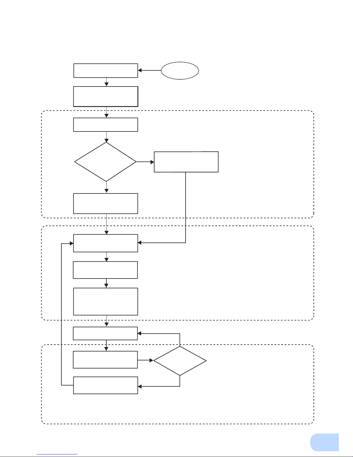
Procedure from installation to operation
Start
Installation/connection
Preparation for operation
Maintenance/
inspection
Yes
No
No
Yes
Read “Safety precautions”
Page v
Remove the product from the
package and check the contents
Page 1
Perform installation and
connection Page 5
Check the operation and
displays Pages 21
Charge the battery
Page 23
Measure the backup time
Page 34
Read “Using the UPS
monitoring software and
contact signal” Page 38
Operate Page 24
Deteriorated
battery?
Perform maintenance
and inspection Page 36
Replace the battery
Are you
using UPS monitoring
software or contact
signal?
Charge the battery again
Page 23
* Preparation for operation is
complete.
Page 5

Table of Contents
iv
Table of Contents
Introduction .........................................................................................................................................i
IMPORTANT SAFETY INSTRUCTION ................................................................................................ ii
Safety precautions .............................................................................................................................v
1. Preparation .....................................................................................................................................1
1-1 Unpacking the product ........................................................................................................................ 1
1-2 Checking the contents ......................................................................................................................... 1
1-3 Name of each part ............................................................................................................................... 2
1-4 Explanation of symbols used on unit................................................................................................... 4
2. Installation and connection ............................................................................................................5
2-1 Precautions and notes on installation and connection ........................................................................5
2-2 Installation ........................................................................................................................................... 9
2-3 Connecting the equipment ................................................................................................................ 14
2-4 Connecting the AC input ................................................................................................................... 18
2-5 Checking the operation ..................................................................................................................... 21
2-6 Charging the battery .......................................................................................................................... 23
2-7 Measuring the initial value of backup time ........................................................................................ 23
2-8 Recharging the battery ......................................................................................................................23
3. Operation ...................................................................................................................................... 24
3-1 Precautions and notes for operation .................................................................................................24
3-2
Start and stop procedures and basic operation ........................................................................................ 26
3-3
Interpreting beeps and displays ................................................................................................................ 29
4. UPS functions ..............................................................................................................................30
4-1 Suspending a beep ............................................................................................................................ 30
4-2 Self-diagnosis test ............................................................................................................................. 30
4-3 Battery life counter function .............................................................................................................. 31
4-4 Operation panel setting ..................................................................................................................... 31
5. Measuring the backup time .......................................................................................................... 34
5-1 How to measure backup time............................................................................................................34
5-2 Estimated backup time ...................................................................................................................... 34
6. Maintenance and Inspection ........................................................................................................36
6-1 Checking the battery ......................................................................................................................... 36
6-2 Cleaning ............................................................................................................................................. 37
7. Using the UPS monitoring software and contact signal ..............................................................38
7-1 When using the included UPS monitoring software to perform auto shutdown ............................... 40
7-2 When performing auto-save functions using the UPS service in
Windows Server 2003/XP/2000 + UPS service driver ....................................................................... 42
7-3 When performing auto-save functions using the standard UPS service in
Windows Server 2003/XP/2000 ......................................................................................................... 43
7-4 Contact signal .................................................................................................................................... 48
8. Using an SNMP/Web card ........................................................................................................... 52
8-1 Adding an SNMP/Web card............................................................................................................... 52
9. Troubleshooting ............................................................................................................................ 53
10. Notes of Chinese ........................................................................................................................ 54
References .......................................................................................................................................66
A. Specifications ......................................................................................................................................... 66
B. Dimensions ............................................................................................................................................. 67
C. Circuit block diagram ............................................................................................................................. 71
D. Related products .................................................................................................................................... 71
Page 6
v
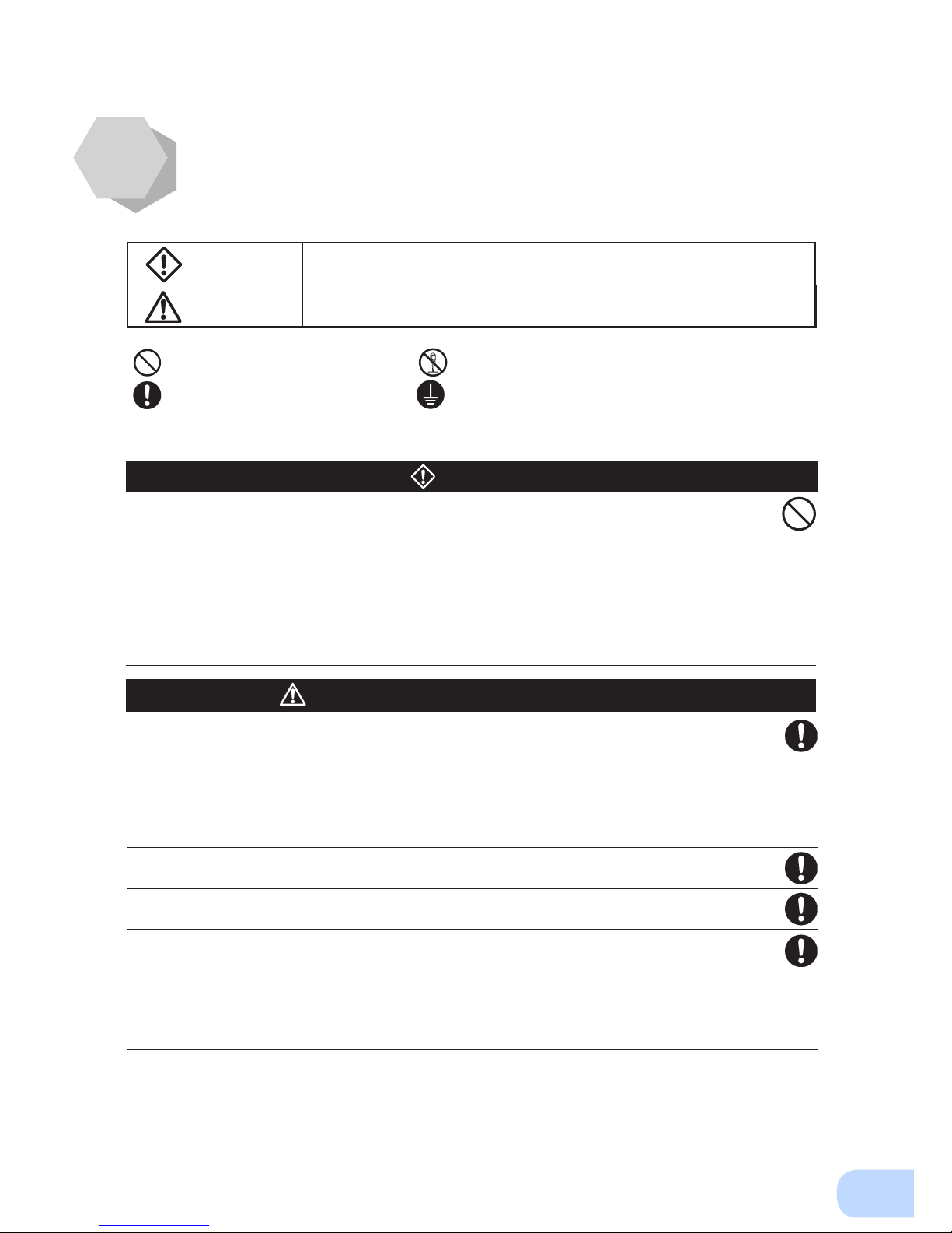
: Indicates prohibition. For example, indicates that disassembly is prohibited.
: Indicates obligation. For example,
indicates that grounding is necessary.
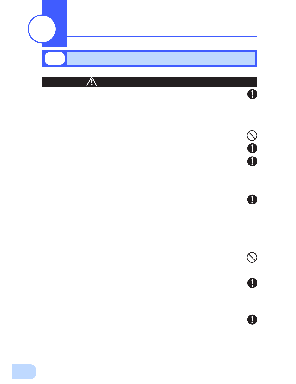
Misuse may cause death or serious injury.
Warning
Caution
Safety precautions
●
The safety symbols and their meaning used in this manual are as follows:
* Property damage means damage to houses/household effects, livestock, and pets.
Note that events categorized as a caution required matter also may cause more serious results under
certain conditions.
Do not use this unit when very high reliability and safety are required as
listed below. This unit is designed and manufactured for use with FA or
OA equipment such as personal computers.
●
Medical equipment or system that may cause death directly.
●
Applications that directly affect the safety of people (For example, the operation and control of
cars and elevators).
●
Applications in which a failure of the unit may cause signicant damage to the society and public
(For example, essential computer systems and main communication equipment.)
●
Applications with the same level of import
ance.
Warning
Important information for safe operation is described.
Be sure to read it before installation and start of use.
Misuse may cause injury or property damage.
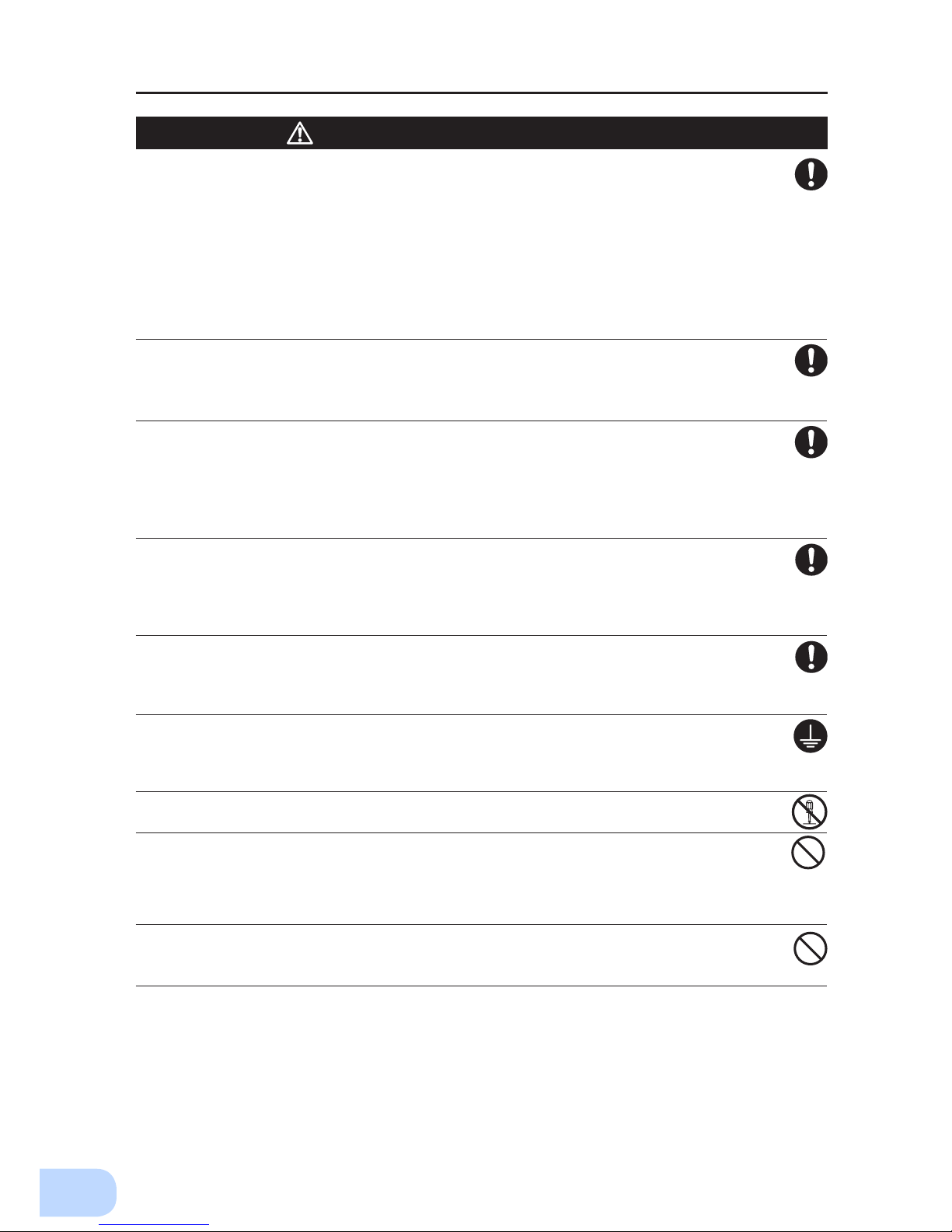
Carry the unit considering its weight and balance, and place it on a stable
and robust base.
●
Dropping or toppling the unit may cause injury.
●
The approximate weights of the units are 28kg (BU2002RWL), 33kg (BU3002RWL) and 61kg
(BU5002RWL).
●
If you drop the unit, stop using it and have it inspected and repaired.
For repair, contact us; ____
Do not hold the side of the front panel when lifting.
●
Injury may result if the panel comes off and falls.
Keep plastic package bags out of reach of children.
●
Children may suffocate if they place their heads into plastic bags.
Make sure to connect the unit’s AC input plug to a commercial power
source with rated input voltage (200/208/220/230/240VAC) and 50/60 Hz
frequency.
●
Connecting to a commercial power source with a different rated input voltage or frequency may
result in a re.
●
The unit may fail.
Caution
(for installation and connection)
Page 7
Safety precautions
vi
For BU5002RWL, when an abnormality (unusual sound or smell) occurs,
disconnect the AC input plug from the wall outlet, or turn OFF the INPUT
PROTECTION switch (input overcurrent protection switch) on the back of
the unit. The socket-outlet shall be installed near the equipment and shall
be easily accessible.
For BU2002RWL and BU3002RWL, turn OFF the external breaker installed
on the input side.
●
When performing maintenance on the connected devices, follow the above instructions to ensure
safety.
Do not connect devices such as dryers, some solenoid valves, etc., which
have a half-wave rectifier that allows only half-cycle AC power to flow
through.
●
Overcurrent may damage the UPS.
Connect the unit to a wall outlet (commercial power) with the appropriate
capacity (11A or greater for BU2002RWL, 16A or greater for BU3002RWL
and 27A or greater for BU5002RWL).
●
Otherwise, the power cord may be heated.
●
When equipment with the maximum output capacity is connected, a maximum current of 11A
(BU2002RWL), 16A (BU3002RWL), or 27A (BU5002RWL) ows.
When changing the input cable, make sure to perform the connection as
specied.
●
When connecting a cable to the terminal block, use a cable that complies with the input current
specication of the UPS.
●
Failure to do so may result in electric shock or ground fault.
When in use, make sure the output terminal block cover is attached. Do
not turn ON the power switch when it is detached.
●
Voltage is applied to the output terminal block when the power switch is ON, which can result in
electric shock.
Provide secure grounding.
●
For AC input plug connection, connect the plug directly to a commercial power source. For termi-
nal block connection, connect the cable to a commercial power source and ground it. A failure or
leak that occurs when the unit is not properly grounded may result in electric shock.
Do not disassemble, repair, or modify the unit.
●
Doing so may cause an electric shock or a re.
Do not install the unit in other than specied orientations.
●
Dropping or toppling the unit may cause injury.
●
If you install the unit in an orientation other than specied, the unit cannot be protected from a
battery uid leakage.
●
Use the included vertical stand when positioning the unit vertically.
Do not use the unit where the maximum temperature exceeds 40°C.
●
The battery deteriorates rapidly.
●
Doing so may cause a failure or malfunction of the unit.
Caution
(for installation and connection)
Page 8
vii
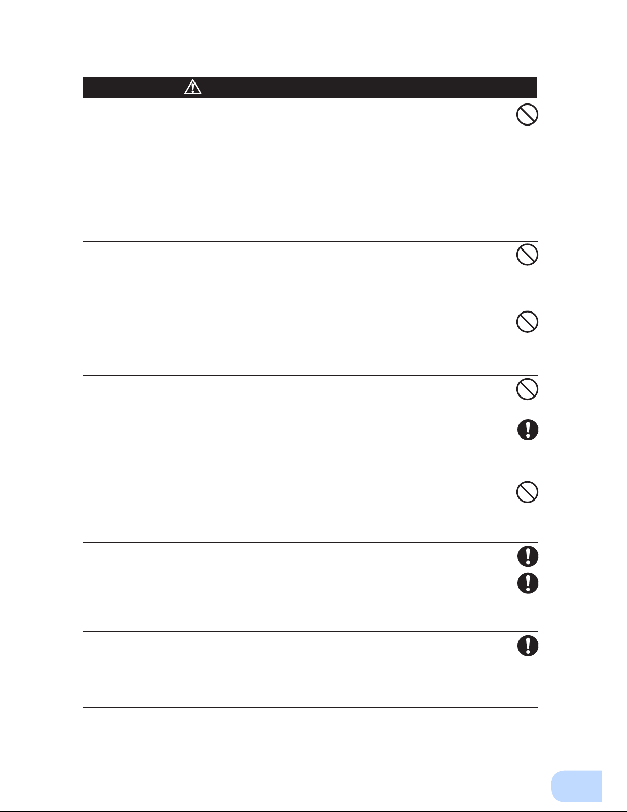
Do not exceed the ranges specied for environmental conditions during
use/storage.
Do not install or store the unit in the places listed below.
●
Do not store in places where the humidity is lower than 10% or higher than 90%.
●
Do not use the unit in places where the ambient temperature is lower than 0°C or higher than
40°C. (With no condensation)
●
Do not use in places where the humidity is lower than 10% or higher than 90%.
●
Do not install/store the unit in closed places such as cabinets with no clearance, places where
there is ammable or corrosive gas, places with large amounts of dust, places exposed to direct
sunlight, places exposed to shock or vibration, salty or wet places, or outdoors.
●
Installation or storing the unit in such a place may cause a re.
Do not connect equipment that exceeds the output capacity of the unit.
You can use plug strip to connect additional devices, but do not connect
devices that exceed the current capacity of the plug strip.
●
The current protection of the unit may operate, which may stop the output.
●
The wiring of the plug strip heats up, which may cause a re.
Do not pinch or sharply bend the cable.
Do not fold or knot the cable.
●
Doing so may cause the cable to be damaged or heated, which may cause an electric shock or a re.
●
If the cable is damaged, stop using the unit and have the cable repaired.
●
For repair, contact us; ____
All of the included accessories are designed to be used exclusively with
the unit. Do not use the accessories with other devices.
●
Doing so may compromise the safety of devices.
Do not block the air vents (front and rear).
●
Doing so will cause the internal temperature to rise, which may cause the unit to fail and the bat-
tery to deteriorate.
●
Leave at least 5 cm of space between the front vent and the wall, and at least 10 cm of space
between the rear vent and the wall.
Do not connect devices that cannot be used with commercial power
supply.
●
When the unit’s power switch is turned ON and an error occurs with the connected device, by-
pass operation is performed and commercial power supply is supplied as is to the connected
devices.
When installing the unit on a rack, place it on the lower shelf.
●
Injury may result if the unit falls.
Make sure to use the mounting screws included with the brackets.
●
Mounting screws other than those included may not be strong enough to support the unit, caus-
ing it to fall.
●
If you attach the case using long screws other than those included with the product, you may
damage the internal parts of the unit.
When using the unit in the 100V output mode, check that the output
voltage is set to 100V, and then turn ON the power switch.
●
Connecting a 100V device to the unit while outputting in the 200V mode may cause a failure of
the device or a re.
●
The output voltage can be set with “Settings” - “In/Out Settings” - “Output Voltage” in the menu
on the LCD.
Caution
(for installation and connection)
Page 9
Safety precautions
viii
Do not allow the unit to come in contact with water.
If you drop the unit, stop using it.
●
Doing so may cause an electric shock or a re.
●
If the unit becomes wet or is dropped, immediately stop using it, disconnect the AC input cable
from commercial power and have the unit inspected and repaired.
●
For repair, contact us; ____.
When the battery is dead, replace it immediately or stop using the unit.
●
Continuing the use of it may cause re or electric shock due to liquid leaks.
Using a dry cloth, periodically wipe the dust from the AC input plug, input
terminal block and power supply output receptacles.
●
Accumulated dust may cause a re.
Do not use the unit in a closed place and do not cover the unit.
●
Doing so may cause abnormal heating or a re.
●
Depending on the operating environment, hydrogen gas may be generated from the battery, re-
sulting in a rupture or explosion. Ventilate the area around the unit.
If you notice an abnormal sound or smell, smoke, or leaking fluid,
immediately turn OFF the unit's power switch and stop the supply of
commercial power.
●
Using the unit under such conditions may cause a re.
●
If you notice such a condition, stop using the unit and contact us at _____ for inspection and repairs.
●
Position the unit in such a way that you can immediately disconnect the AC input plug from the
wall outlet (commercial power) in the event a problem occurs.
If uid leaks from the unit, do not touch the uid.
●
Doing so may cause blindness or burns.
●
If the uid contacts your eyes or skin, wash it out with lots of clean water and consult your doctor.
Do not place objects heavier than 25 kg on the unit, and do not drop
heavy objects onto the unit.
●
Doing so may cause distortion/damage to the case or a failure of the internal circuit, which may
cause a re.
The unit is equipped with a bypath circuit which is able to supply electric
power to connected devices even when the inner control circuit is broken
down by defects or malfunctions
●
Output is continuing even when all indicators of the front panel are off.
●
If you want to stop the output, either stop the source of commercial power or disconnect the AC
input plug from the wall outlet (commercial power).
Do not sit or stand on top of the product, use it as a step ladder, or lean
against it.
●
Doing so may cause the unit to fail or to fall over and result in injury.
* The values in the table are the expected life under stan-
dard use conditions and are not guaranteed.
Caution
(for use)
Ambient temperature Expected life
25°C 5 years
35°C 2.5 years
Page 10
ix
When maintaining the connected equipment, turn OFF the unit’s power
switch to stop the output, and stop the supply of commercial power.
●
Even if commercial power to the UPS is stopped while it is in operation, the power output of this
unit does not stop and power is supplied from the receptacle.
Do not disassemble, repair, or modify the unit.
●
Doing so may cause an electric shock or a re.
If uid leaks from the unit, do not touch the uid.
●
Doing so may cause blindness or burns.
●
If the uid contacts your eyes or skin, wash it out with lots of clean water and consult your doctor.
Do not throw the unit into re.
●
The lead battery in the unit may explode, or leak dilute sulfuric acid.
Do not insert metal objects into the power supply output receptacle of the
UPS.
●
Doing so may result in electric shock.
Do not insert metal objects into the battery connectors.
Do not create a short between the connector terminals.
●
Doing so may result in electric shock.
Perform replacement on a stable and at place.
●
Handle the battery carefully so that you do not drop it.
●
Not doing so could cause injury or burns due to liquid (acid) leakage.
Use a specied battery for replacement.
●
Not doing so may cause a re.
●
Replacement battery pack for
BU2002RWL: BUB2002RW
BU3002RWL: BUB3002RW
BU5002RWL: BUB3002RW (2PCS.)
Do not replace the battery in a place where there is ammable gas.
●
Spark may occur when connecting the battery, which may cause an explosion or re.
If uid (dilute sulfuric acid) leaks from the battery, do not touch the uid.
●
Doing so may cause blindness or burns.
●
If it contacts your eyes or skin, wash it out with lots of clean water and consult your doctor.
Do not disassemble or modify the battery.
●
Doing so could cause dilute sulfuric acid leak, which could cause blindness and burns.
Do not drop the battery and do not expose it to strong impact.
●
Dilute sulfuric acid may leak.
Do not short the battery with metal objects.
●
Doing so could cause an electric shock, re or burn.
●
Some electrical energy still remains inside the spent battery.
Do not put the battery into re and do not break it.
●
The battery may explode or leak dilute sulfuric acid.
Do not use a new battery and an old battery at the same time.
●
Dilute sulfuric acid may leak.
Caution
(for maintenance)
Caution
(for battery replacement)
Page 11

Safety precautions
x
Notes
When moving the unit from a cold place to a warm place, leave it for several
hours before using it.
●
If the unit is promptly turned ON after being moved to a warmer place, condensation may form inside the
unit and cause it to fail.
Charge the battery soon after purchasing the unit.
●
If you do not use the unit for a long time after the purchase, the battery may deteriorate and the battery
may become unusable.
●
The battery can be charged once the AC input plug is connected to commercial power.
Recharge the battery for at least 8 hours every 6 months when the storage
temperature is 25°C or less, or every 2 months when the storage temperature is
40°C or less.
●
The battery self-discharges even when it not being used, and it goes into over-discharge state if it is left
for a long period of time. The backup time may become shorter or the battery may become unusable.
●
We recommend keeping the temperature 25°C or less when storing the unit for long periods of time.
●
Turn OFF the unit’s power switch when storing it.
Do not short the output lines of the unit to each other, and do not short the
output lines to the ground.
●
The unit may fail.
Do not connect the AC input terminal of the unit to its Power Supply Output
terminal during the Battery Mode.
●
The unit may fail.
Do not connect a page printer (such as a laser printer) to the unit.
●
The unit repeatedly and frequently switches between Commercial Power Mode and Battery Mode, which
may shorten the life of the battery.
●
The page printer has a large peak current, so an excess of the connection capacity or a power failure due
to instantaneous voltage drop may be detected.
Do not install or store the unit in a place exposed to direct sunlight.
●
The rise of temperature may cause the built-in battery to deteriorate rapidly and become unusable.
Do not perform withstand voltage tests.
●
Performing withstand voltage tests may damage the surge absorption element built into the power supply
input circuit.
●
When performing an insulation resistance test, use the 400 VDC range.
Before stopping the commercial power to the unit, turn OFF the power switch of
the unit.
●
The unit enters Battery Mode when commercial power is stopped. If you frequently use the unit in Battery
Mode, the battery life may be signicantly shortened.
If this unit is used for an inductive device such as a coil or motor, check the
operation beforehand.
●
With some types of devices, the effect of inrush current may cause this unit to stop operating properly.
Page 12
xi
Explanation
Usual operation
●
You may either leave the power switch of the unit ON (operation status) or turn it OFF each time when
stopping the connected system. Choose whichever operation method is more convenient. We recommend
turning OFF the power switch when you do not use connected devices for a long time.
●
The battery can be charged once the unit is connected to a commercial power source.
Quitting Battery Mode
●
If a power failure lasts for an extended period of time, the battery discharges completely and power output
from the unit stops. Shut down your computer after performing appropriate procedures (for example, saving data) while the unit is still supplying power.
Rebooting
●
If the battery discharges completely during a power failure, the output stops. After recovery from the
power failure, the unit automatically restarts and output begins. If you do not want to restart the connected
devices, disable the “Settings” - “Boot Settings” - “Auto reboot” setting in the menu on the unit’s LCD, or
turn OFF the power switch of the connected devices.
Scheduled operation using the UPS monitoring software
●
When performing scheduled operation in which the UPS is stopped and a device such as a breaker is
used to stop the UPS at the same time that commercial power stops, specify a period of no more than 3
months for the start of the next operation.
If
you specify a period longer than 3 months, the internal timer is reset and the scheduled operation does
not start. Note that this period reduces to approximately half when the battery needs to be replaced. If a
period of 3 months is exceeded, you start operation by supplying commercial power and pressing the start
switch. However, if the battery needs to be replaced, you may not be able to start operation.
In this case, replace the battery
.
Pb
Notes
Check system operation beforehand if the unit is used in combination with a
device whose power supply voltage and frequency uctuate widely, such as a
generator.
●
If the generator’s output voltage/frequency falls out of the input voltage/frequency range, the unit will enter
Battery Mode.
●
Even if the input frequency is within the range, the unit will enter Battery Mode when a rapid change (5
Hz/sec or greater) occurs.
In the event you transfer or sell this unit to a third party, please include all of the
documentation that came with the unit. This is to ensure that the unit is used in
line with the conditions described in the included documentation.
●
This manual contains important safety-related information. Please read and understand the contents of
the manual before beginning operation.
This unit uses lead acid batteries,
●
Which are a valuable recyclable resource. Please recycle.
Take measures for handling unforeseen accidents, such as data backup and
system redunda
ncy.
●
The output may stop when there is a circuit failure in the UPS.
Page 13
1
Open the package box and take out the UPS and accessories.
The approximate masses of the units are 28kg (BU2002RWL), 33kg
(BU3002RWL) and 61kg (BU5002RWL) . Since the unit is heavy, be
careful not to hurt yourself when lifting or transporting it.
Hold the handle of the inner packaging when taking out the product
from the package box.
●
Hold the handle of the inner packaging when taking out the product from the package box.
●
Dropping may cause injury.
Caution
Warranty
Instruction manual
(Japanese/English
edition)
Label (How to
determine
operating status)
Rubber feet Battery
replacement
date label
User registration
card/sheet
OMRON
contact
info label
EIA/JIS 19-inch rack
mount support angles
Ear BracketTerminal
block cover
(with cable
clamp)
Upright stand
CD-ROM
<Accessories related to main unit> <UPS monitoring software>
Connection cable(RS-232C)
(Approx. 2.2 m)
1-1
Unpacking the product
Preparation
1
1-2
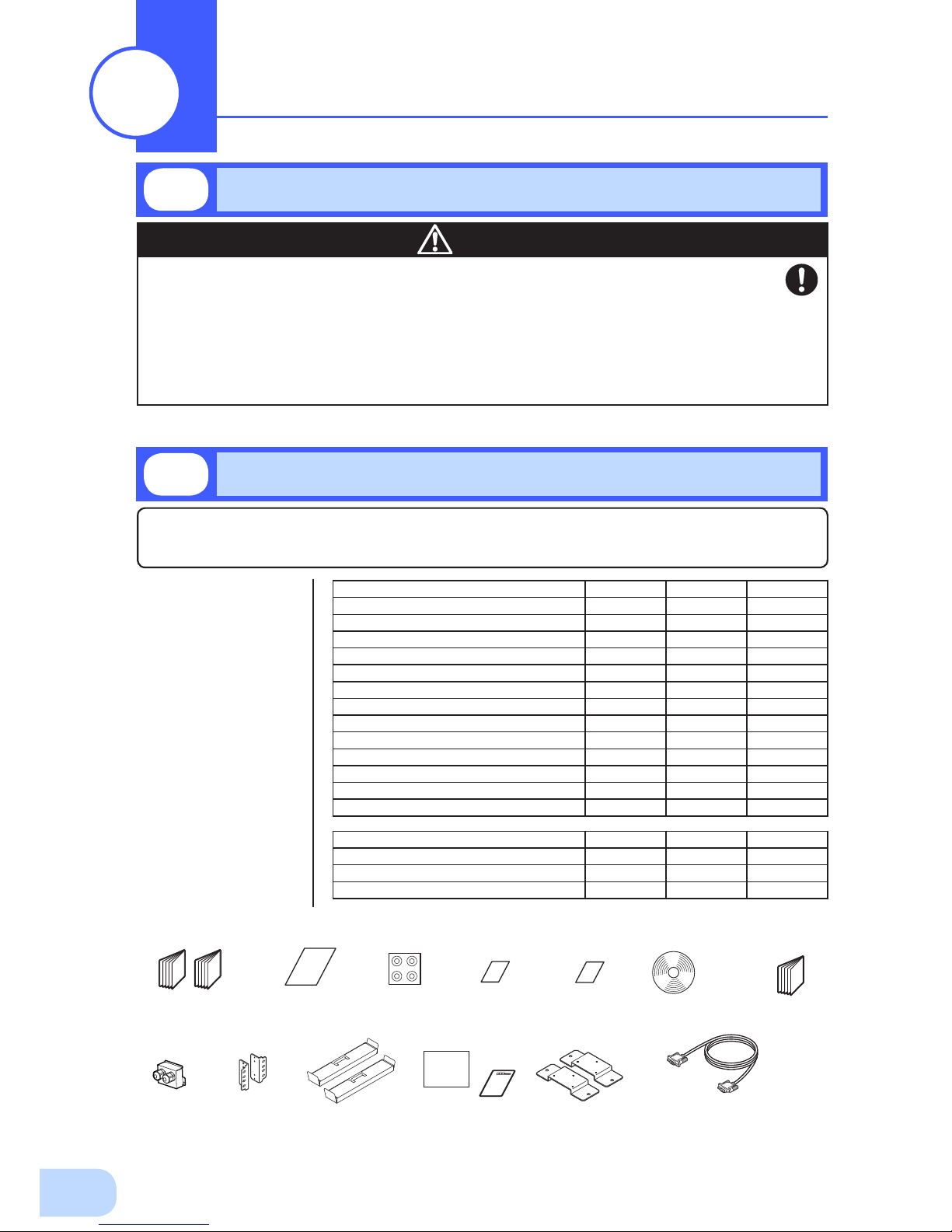
Checking the contents
Check whether all the package contents are included and there is no damage found on their appearance.
If you should notice defects or anything wrong, contact us; OMRON Electronic Systems & Equipments
Customer Support Center.
(1)
Accessories
related to the
main unit
(2) UPS
monitoring
software
related items
Quick installation
guide
BU2002RW BU3002RW BU5002RW
Instruction manual (Japanese/English) 1 each 1 each 1 each
Warranty card (Japanese/Chinese) 1 each 1 each 1 each
User registration card/sheet 1 each 1 each 1 each
Vertical stand 2 per set 2 per set 2 per set
Support angles compatible with EIA/JIS 19-inch racks
1 set 1 set 1 set
Omron contact info label 1 1 1
Battery replacement date label 1 1 1
Rubber feet 6 per set 6 per set 6 per set
Serial number label 4 4 4
Ear bracket
2 per set 2 per set 2 per set
Terminal block cover (with cable clamp)
1 1 1
SC20G (included accessory)
- - 1 set
Bracket screws
1 set 1 set 1 set
BU2002RW BU3002RW BU5002RW
Quick Install Guide
1 1 1
CD-ROM
1 1 1
Connection cable (RS232C)
1 1 1
Page 14
BU2002RWL/BU3002RWL/BU5002RWL
1
2
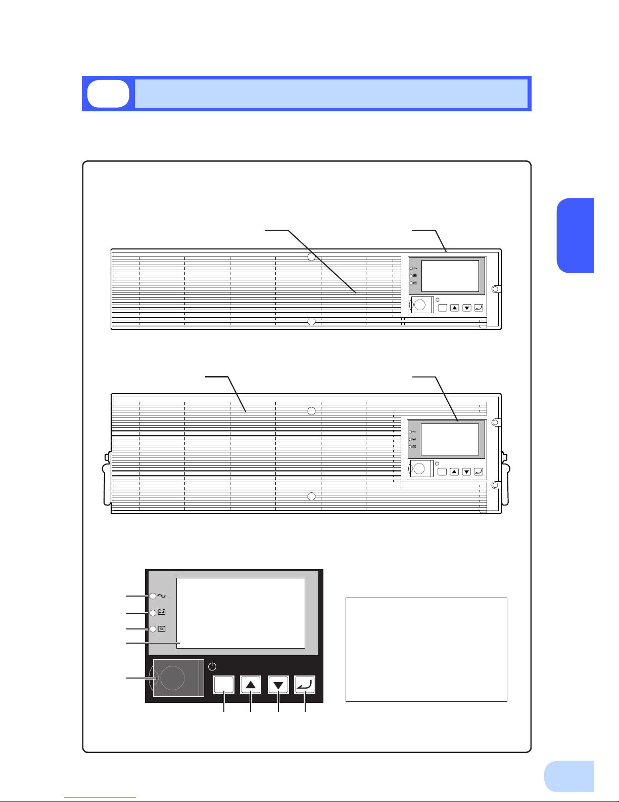
This section describes the name of each part of the UPS.
For information on the function of each part, refer to "2. Installation and connection" on page 5 and
"3. Operation" on page 24 that provides the details.
Front view
< Enlarged view of the operation panel >
A. Power supply output lamp
B. Battery mode lamp
C. Battery replacement lamp
D. LCD for status and setting display
E. Power switch
F. ESC switch
G. Up switch
H. Down switch
I. Enter switch
1-3
Name of each part
< BU2002RWL/BU3002RWL >
< BU5002RWL >
ESC
<Air vent> <Operation panel>
ESC
ESC
A
B
C
D
E
F G H I
<Operation panel><Air vent>
Page 15
1.Preparation
3
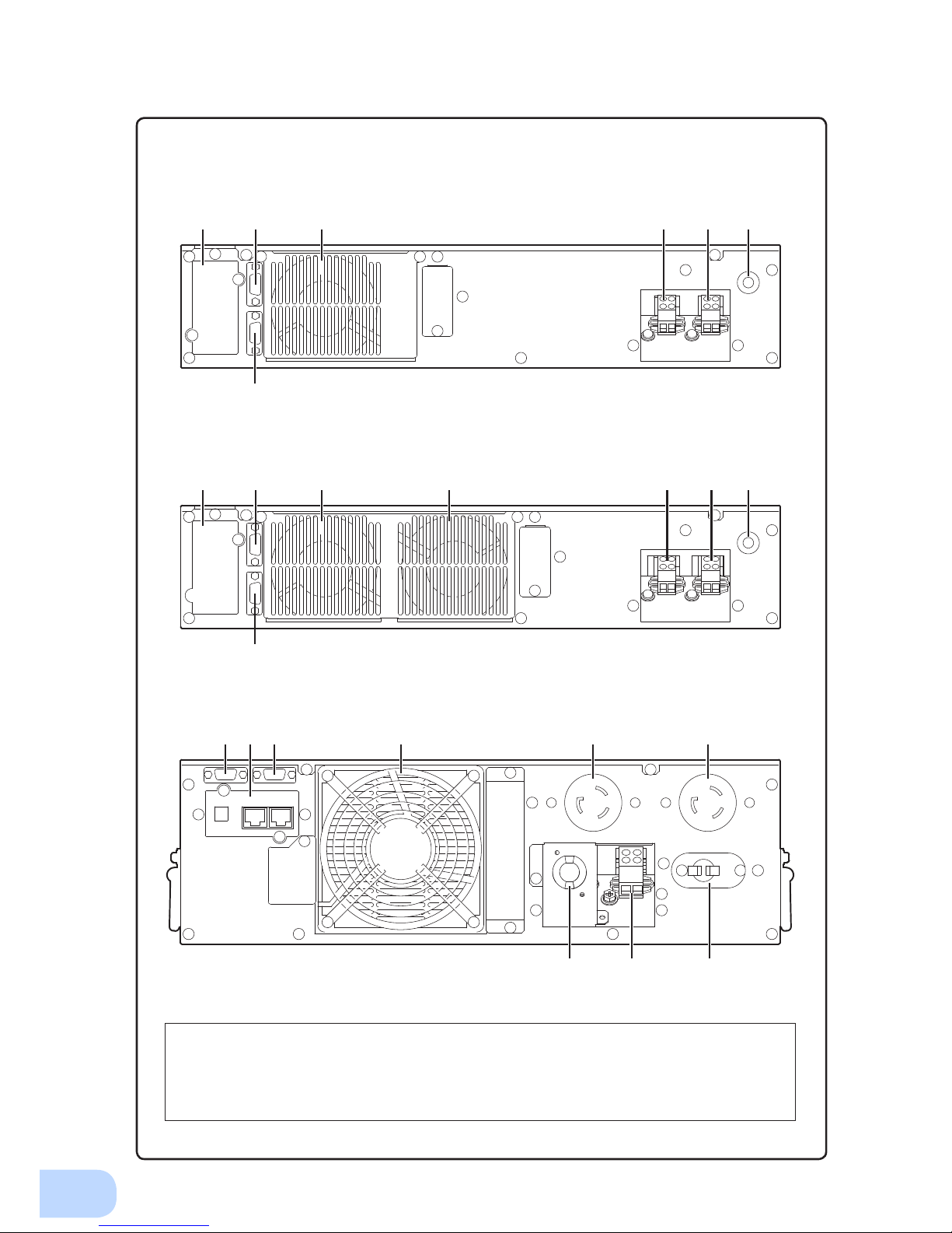
Rear view
A. Option slot
B. Contact signal port
C. RS-232C port
D. Cooling fan
E. AC input terminal block
F. AC output terminal block
G. AC input overcurrent protection switch
H. AC input cable
I. AC output receptacle
< BU2002RWL >
< BU3002RWL >
< BU5002RWL >
A B D D E F G
C
A B D E F G
C
I IB
F G
A C D
H
Page 16
BU2002RWL/BU3002RWL/BU5002RWL
1
4
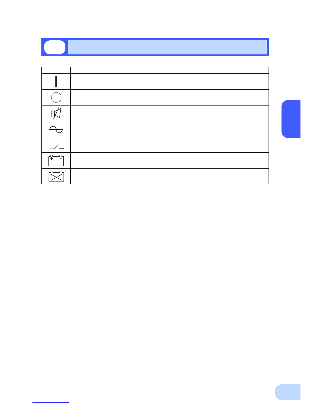
1-4
Explanation of symbols used on unit
Symbol Description
Start the UPS.
Stop the UPS.
Suspend a beep.
UPS output power enabled, supplied by operating on line mode, battery mode.
Bypass output “ON”.
UPS output power enabled, supplied by operating on battery mode.
Batteries at end of useful life, necessary to replace the batteries.
Page 17
5
Carry the unit considering its weight and balance, and place it on a stable
and robust base.
●
Dropping or toppling the unit may cause injury.
●
The approximate weights of the units are 28kg (BU2002RWL), 33kg (BU3002RWL) and 61kg
(BU5002RWL).
●
If you drop the unit, stop using it and have it inspected and repaired.
For repair, contact us; ____
Do not hold the side of the front panel when lifting.
●
Injury may result if the panel comes off and falls.
Keep plastic package bags out of reach of children.
●
Children may suffocate if they place their heads into plastic bags.
Make sure to connect the unit’s AC input plug to a commercial power
source with rated input voltage (200/208/220/230/240VAC) and 50/60Hz
frequency.
●
Connecting to a commercial power source with a different rated input voltage or frequency may
result in a re.
●
The unit may fail.
For BU5002RWL, when an abnormality (unusual sound or smell) occurs,
disconnect the AC input plug from the wall outlet, or turn OFF the INPUT
PROTECTION switch (input overcurrent protection switch) on the back of
the unit. The socket-outlet shall be installed near the equipment and shall
be easily accessible.
For BU2002RWL and BU3002RWL, turn OFF the external breaker installed
on the input side.
●
When performing maintenance on the connected devices, follow the above instructions to
ensure safety
.
Do not connect devices such as dryers, some solenoid valves, etc. ,
which have a half-wave rectier that allows only half-cycle AC power to
ow through.
●
Overcurrent may damage the UPS.
Connect the unit to a wall outlet (commercial power) with the appropriate
capacity (11A or greater for BU2002RWL, 16A or greater for BU3002RWL
and 27A or greater for BU5002RWL).
●
Otherwise, the power cord may be heated.
●
When equipment with the maximum output capacity is connected, a maximum current of 11A
(BU2002RWL), 16A (BU3002RWL), or 27A (BU5002RWL) ows.
When changing the input cable, make sure to perform the connection as
specied.
●
When connecting a cable to the terminal block, use a cable that complies with the input current
specication of the UPS.
●
Failure to do so may result in electric shock or ground fault.
2-1
Precautions and notes on installation and connection
Installation and connection
2
Caution
(for installation and connection)
Page 18
BU2002RWL/BU3002RWL/BU5002RWL
2
6
When in use, make sure the output terminal block cover is attached. Do
not turn ON the power switch when it is detached.
●
Voltage is applied to the output terminal block when the power switch is ON, which can result in
electric shock.
Provide secure grounding.
●
For AC input plug connection, connect the plug directly to a commercial power source. For termi-
nal block connection, connect the cable to a commercial power source and ground it. A failure or
leak that occurs when the unit is not properly grounded may result in electric shock.
Do not disassemble, repair, or modify the unit.
●
Doing so may cause an electric shock or a re.
Do not install the unit in other than specied orientations.
●
Dropping or toppling the unit may cause injury.
●
If you install the unit in an orientation other than specied, the unit cannot be protected from a
battery uid leakage.
Do not use the unit where the maximum temperature exceeds 40°C.
●
The battery becomes weak rapidly, which may cause a re.
●
Doing so may cause a failure or malfunction of the unit.
Do not exceed the ranges specied for environmental conditions during
use/storage.
Do not install or store the unit in the places listed below.
●
Do not store in places where the humidity is lower than 10% or higher than 90%.
●
Do not use the unit in places where the ambient temperature is lower than 0°C or higher than
40°C. (With no condensation)
●
Do not use in places where the humidity is lower than 10% or higher than 90%.
●
Do not install/store the unit in closed places such as cabinets with no clearance, places where
there is ammable or corrosive gas, places with large amounts of dust, places exposed to direct
sunlight, places exposed to shock or vibration, salty or wet places, or outdoors.
●
Installation or storing the unit in such a place may cause a re.
Do not connect equipment that exceeds the output capacity of the unit.
You can use a plug strip to connect additional devices, but do not connect
devices that exceed the current capacity of the plug strip.
●
The current protection of the unit may operate, which may stop the output.
●
The wiring of the plug strip heats up, which may cause a re.
Do not pinch or sharply bend the cable.
Do not fold or knot the cable.
Doing so may cause the cable to be damaged or heated, which may cause
an electric shock or a re.
●
If the cable is damaged, stop using the unit and have the cable repaired.
For repair
, contact us; ____
The accessories are designed exclusively for use with this unit.
Do not use any of the included accessories with other devices.
●
Doing so may compromise the safety of devices.
Do not block the air vents (front and rear).
●
Doing so will cause the internal temperature to rise, which may cause the unit to fail and the bat-
tery to deteriorate.
●
Leave at least 5 cm of space between the front vent and the wall, and at least 10 cm of space
between the rear vent and the wall.
Caution
(for installation and connection)
Page 19
2.Installation and connection
7
Do not connect devices that cannot be used with commercial power
supply.
●
When the unit’s power switch is turned ON and an error occurs with the connected device, by-
pass operation is performed and commercial power supply is supplied as is to the connected
devices.
When installing the unit on a rack, place it on the lower shelf.
●
Injury may result if the unit falls.
Make sure to use the mounting screws included with the brackets.
●
Mounting screws other than those included may not be strong enough to support the unit, caus-
ing it to fall.
●
If you attach the case using long screws other than those included with the product, you may
damage the internal parts of the unit.
When using the unit in the 100V output mode, check that the output
voltage is set to 100V, and then turn ON the power switch.
●
Connecting a 100V device to the unit while outputting in the 200V mode may cause a failure of
the device or a re.
●
The output voltage can be set with “Settings” - “In/Out Settings” - “Output Voltage” in the menu
on the LCD.
Caution
(for installation and connection)
Page 20

BU2002RWL/BU3002RWL/BU5002RWL
2
8
Notes
When moving the unit from a cold place to a warm place, leave it for several
hours before using it.
●
If the unit is promptly turned ON after being moved to a warmer place, condensation may form inside the
unit and cause it to fail.
Charge the battery soon after purchasing the unit.
●
The battery self-discharges even when it not being used, and it goes into over-discharge state if it is left
for a long period of time.
●
The battery can be charged once the AC input plug is connected to a commercial power source.
When storing the unit, charge the battery for at least 8 hours and turn OFF the
power switch.
●
Even if the unit is not used, the battery gradually discharges, and if it is left for a long time, it goes into an
over discharge state.
The backup time may become shorter or the battery may become unusable.
●
Connect the unit to a commercial power source for at least 12 hours every 6 months when the storage
temperature is 25°C or less, or every 2 months when the storage temperature is 40°C or less.
●
Turn off the power switch of the unit during storage.
Do not short the output lines of the unit to each other, and do not short the
output lines to the ground.
●
The unit may fail.
Do not connect the AC input plug of the unit to its Power Supply Output
Receptacle during the Battery Mode.
●
The unit may fail.
Do not connect a page printer (such as a laser printer) to the unit.
●
The unit repeatedly and frequently switches between Commercial Power Mode and Battery Mode, which
may shorten the life of the battery.
●
The page printer has a large peak current, so an excess of the connection capacity or a power failure due
to instantaneous voltage drop may be detected.
Do not install or store the unit in a place exposed to direct sunlight.
●
The rise of temperature may cause the built-in battery to deteriorate rapidly and become unusable.
Do not perform withstand voltage tests.
●
Performing withstand voltage tests may damage the surge absorption element built into the power supply
input circuit.
●
When performing an insulation resistance test, use the 400 VDC range.
Before stopping the commercial power to the unit, turn OFF the power switch of
the unit.
●
The unit enters Battery Mode when commercial power is stopped. If you frequently use the unit in Battery
Mode, the battery life may be signicantly shortened.
If this unit is used for an inductive device such as a coil or motor, check the
operation beforehand.
●
With some types of devices, the effect of inrush current may cause this unit to stop operating properly.
The battery contains dilute sulfuric acid which is a toxic substance. If uid leaks
from the battery, do not let it contact your skin or clothes. If contacted, wash
it out with clean water. In particular, if the uid gets in your eyes, immediately
wash them with clean water and seek medical treatment.
Check system operation beforehand if the unit is used in combination with a
device whose power supply voltage and frequency uctuate widely, such as a
generator.
●
If the generator’s output voltage/frequency falls out of the input voltage/frequency range, the unit will enter
Battery Mode.
●
Even if the input frequency is within the range, the unit will enter Battery Mode when a rapid change (5
Hz/sec or greater) occurs.
Page 21
2.Installation and connection
9
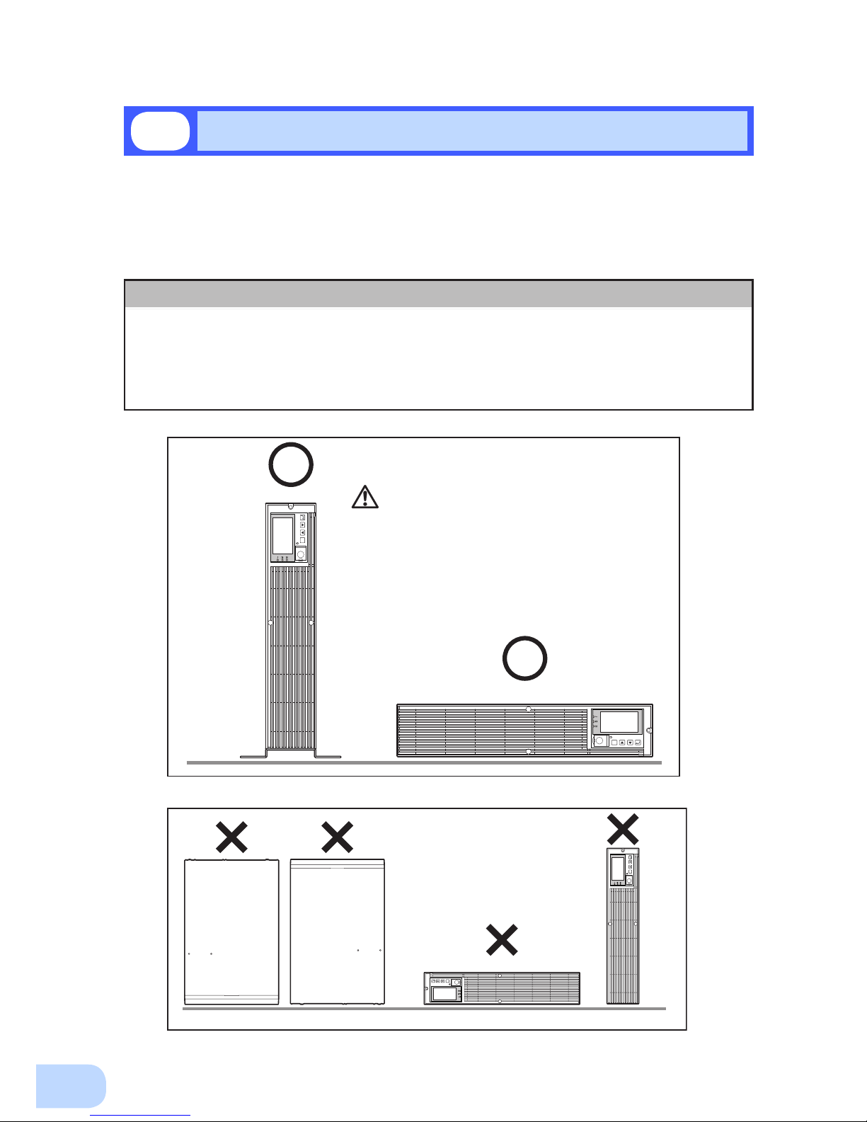
Do not use this unit in any position other than the “correct positions” indicated in the illustration below.
Note
Before installing this device, make a record of the serial number of this device.
The product serial number is required when contacting us about the device.
The serial number (S/N) is inscribed on the bottom left side of the rear panel.
The product serial number is inscribed on the bottom left side of the rear
panel. The product serial number label is also included.
2-2
Installation
Correct Positions
Be careful not to get your fingers caught
when arranging the unit.
ESC
ESC
ESC
ESC
IncorrectPositions
The UPS permits the following installing methods. Choose the one best suited for the environment.
2-2-1. Rackmount installation
2-2-2. Stationary installation
●
Horizontal
●
Upright intatllation
Page 22
BU2002RWL/BU3002RWL/BU5002RWL
2
10
When performing rack installation, ensure that the UPS is supported and
stabilized by using both the support angles and the table clamps that
were included.
●
When installing on a rack, make sure that the UPS is supported by the each unit individually.
●
When installing on a rack, make sure to use the support angles and table clamps included with the
product. Without the support angles, the front clamp alone cannot support the weight of the UPS.
●
The mass of each unit: BU2002RWL: Approx. 28kg BU3002RWL: Approx. 33kg
BU5002R
WL: Approx. 61kg
In a case where the UPS is to be mounted on a rack, place it on the lower
part of the rack.
●
Dropping it may result in injury.
Be sure to use the supplied mounting screws.
●
Use of long screws other than those supplied for case mounting may damage inside the unit.
●
Screws other than those supplied may not be strong enough to support the UPS, causing it to fall.
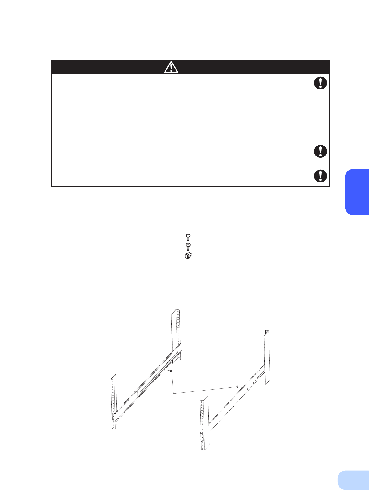
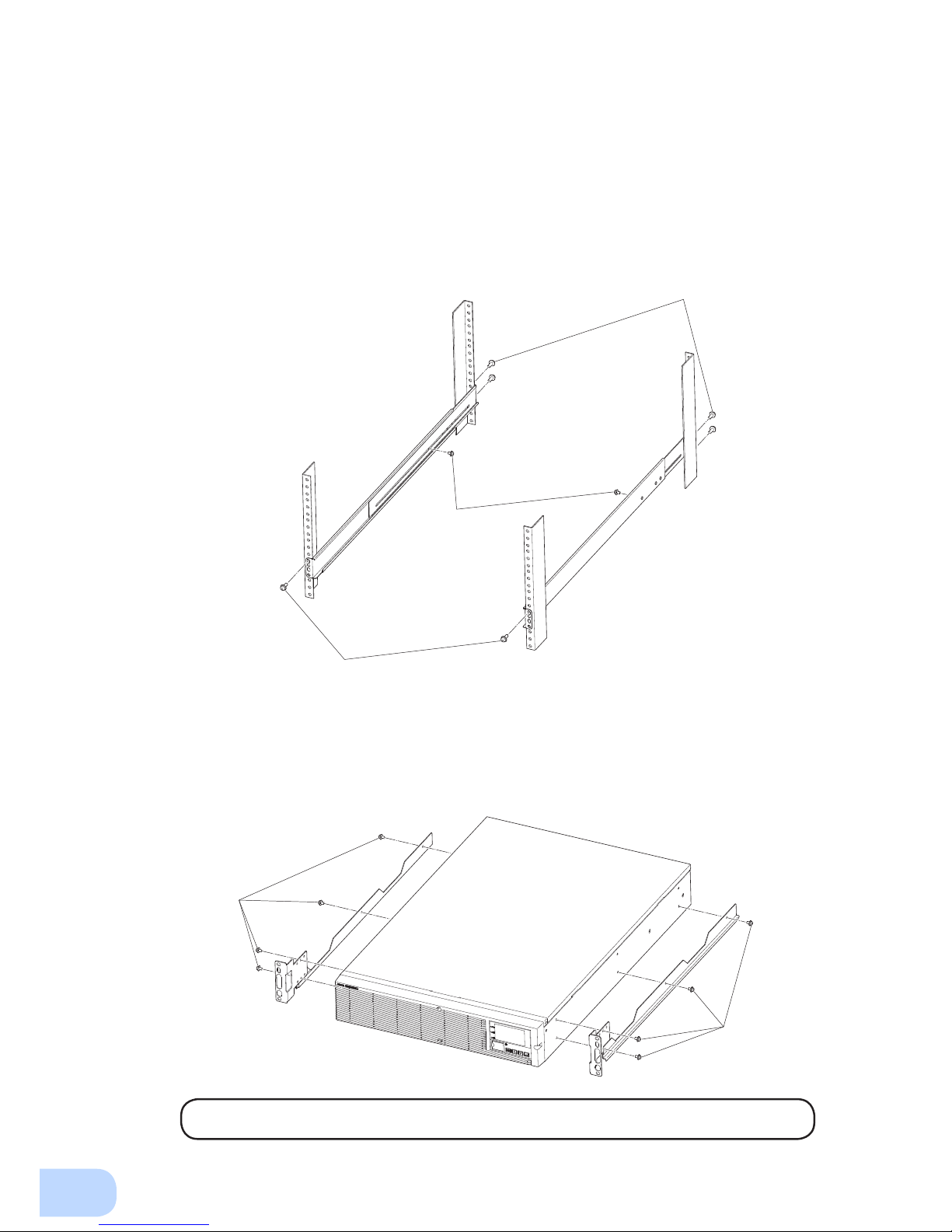
2-2-1. Rackmount installation (EIA /JIS 19-inch rack/server rack)
●
Rack mounting procedure
(1) Insert the 2 included bracket mounting screws (M4) and half-tighten them to hold the front
and rear rack rails in place.
①
There are two types of front and rear rack rails: left (L) and right (R).
Caution
●
Items included in the 19-inch rack support angle mounting bracket set
Rack rail (front) L/R ........................................ 1 each
Rack rail (rear) L/R .........................................1 each
Unit guide rail L/R ..........................................1 each
Ear bracket L/R ..............................................1 each
Spacers .................................................................. 2
Bracket mounting screws (M4) ................ ............ 10
EIA/JIS rack fixing screws (M5) ........................... 10
EIA rack fixing nuts (M5) ...................................... 10
2 bracket fixing
screws (M4)
①
Page 23
2.Installation and connection
11
(3) For EIA standard-compliant installation, use the included EIA rack xing nuts (M5) and EIA/
JIS rack xing screws (M5) to securely fasten the front and the back of the rack rails to the
server rack. ③ The screw hole positions are as follows.
• EIA rack : Topmost one for the front, topmost and bottommost ones for the rear
• JIS rack : One at the second from the bottom for both front and rear
(4) Use the 8 included bracket xing screws (M4) (2 sets of 4 screws) to securely fasten the ear
brackets and unit guide rails to the left and right sides of the UPS. ④
(Installation is possible without removing the handles on the sides of BU5002RWL; do not
remove them.)
The support angles cannot be attached to special EIA/JIS racks.
(2) Adjust the length of support angles to suit the server rack, and then securely tighten the
screws that were half-tightened in step 1.
②
③
②
③
Rack fixing screws
Adjust the length to
suit the server rack
and tighten securely.
④
④
Page 24
BU2002RWL/BU3002RWL/BU5002RWL
2
12
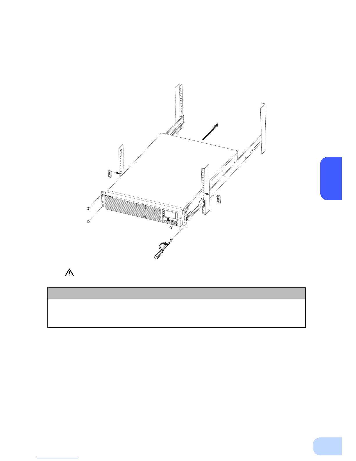
Always use the support angles.
(5) Place the UPS on the support angles and push it completely into the rack ⑤, and use the
included EIA/JIS rack xing screws (M5) and spacers to securely fasten the ear brackets to
the server rack. ⑥ The screw hole positions are as follows.
• EIA rack : Topmost and bottommost ones on the front
• JIS rack : One at the second from the top on the front
⑥
⑤
Push completely in
Use the unit
fixing screws to
fasten
Note
The batteries for BU5002RWL are in a separate package. Attach the batteries
to the unit before installation. For the attachment procedure, refer to "6-2
Replacing the battery".
Page 25

2.Installation and connection
13
2-2-2. Stationary installation
Perform installation only as shown in the diagrams below.
●
Horizontal installation
Attach the included rubber feet for horizontal installation with the included M3 screws and
position the unit horizontally.
For stationary horizontal installation, make sure that this product does not slide or fall.
(Installation is possible without removing the handles on the sides of BU5002RWL; do not remove them.)
●
Upright installation
(1) Upright installation
Use the upright stands included with the product.
Attach the two upright stands (front and back) for BU2002RWL and BU3002RWL, and three
(front, center, and back) for BU5002RWL with the included screws.
Keep a space of 250 mm or more above the UPS.
(Installation is possible without removing the handles on the sides of BU5002RWL; do not
remove them.)
ESC
ESC
Note
The batteries for BU5002RWL are in a separate package. Attach the batteries
to the unit before installation. For the attachment procedure, refer to "6-2
Replacing the battery".
Page 26

BU2002RWL/BU3002RWL/BU5002RWL
2
14
2-3
Connecting the equipment
Caution
Do not connect devices with rated voltage of 200 to 240/100VAC or
higher.
●
The rated output voltage of this device is 200 to 240/100VAC.
●
Overcurrent may damage the connected devices.
PC server
NEMA L6-30P
(1) BU5002RWL comes equipped with two “NEMA L6-30R” AC receptacles. Only devices with rated
voltage of 200 to 240 VAC can be connected to these AC receptacles. Connect devices with rated
voltage of 100 VAC to the AC output terminal block.
(2) Connect devices you want to back up to the Power Supply Output Receptacles of the UPS.
• If you need more output receptacles than those of the UPS, supply additional output receptacles.
2-3-1. Connecting a device to the power supply output
(AC receptacle) (BU5002RWL only)
< Example of connection for BU5002RWL >
Page 27

2.Installation and connection
15
Caution
2-3-2.
Connecting a device to the power supply output (AC output terminal block)
When in use, make sure the output terminal block cover is attached. Do
not turn ON the power switch when it is detached.
●
Voltage is applied to the output terminal block when the power switch is ON, which can result in
electric shock.
When connecting a device to the output terminal block, make sure to include
an emergency stop switch (ESD) between the unit and the load.
●
In the event of an accident, the power supply to the device can be stopped by pressing the emergency
stop switch.
●
To reduce the risk of re, connect only to an emergency stop switch (ESD) with a minimum rating of
250V/15A (BU2002RWL), 250V/20A (BU3002RWL), or 250V/30A (BU5002RWL). When the unit is used
in compliance with UL standards or CE marking, follow the National Electrical Code (ANSI/NFPA 70).
●
Install the emergency stop switch where it is easy to operate.
ESD
Emergency
Stop Switch
daoLSPU
(1) Connect the devices that require backup to the power supply output terminal block of the unit.
Check that one terminal block cover and three M3 screws are included in the accessories.
BU2002RWL and BU3002RWL require two M3 screws, and BU5002RWL requires one M3 screw.
(The remaining M3 screws are spares.)
Run the wires to be connected through the hole in the terminal block cover (with cable clamp).
(See Figure 1.)
If you have trouble running the wire through the hole, loosen the cable clamp dial by turning it
counter-clockwise.
Crimp the specied round terminal to the ground wire, and tighten the ground terminal screw. (See
Figure 2.)
Use a at head screwdriver to loosen the terminal block screws, insert the wire stripped to the
specied length into the terminal block from the bottom at an angle as far as it will go, and then
retighten the terminal block screws. (See Figure 3.)
The wire connected to the G terminal should be longer than the wires connected to L1 and L2.
Refer to Table 1 for wire sizes.
G terminal : Connect the ground wire
L1 terminal : Connect the line
L2 terminal : Connect the neutral line
Page 28

BU2002RWL/BU3002RWL/BU5002RWL
2
16
Table 1
BU2002RWL
BU3002RWL
BU5002RWL
Connectable wire size 0.5 to 4mm
2
1.5 to 6mm
2
Amount of stripped wire 6 to 8mm 9 to 11mm
Tightening torque 0.49N•m 1.18N•m
Recommended cable size 2mm
2
(AWG14) 3.5mm2 (AWG12)
Figure 1
BU2002RWL/BU3002RWL
BU2002RWL/BU3002RWL
BU5002RWL
BU5002RWL
Figure 2
Figure 3
Crimp the round terminal to the ground wire.
BU2002RWL/BU3002RWL : For M4 screw
BU5002RWL : For M5 screw
φ
INPUT
OUTPUT
1
50-60Hz
G
L2
L1
G
L2
L1
170-278VAC
15A
φ
1
1
00/
200/208/
220/230/240VAC
50-60Hz
15A
INPUT
OUTPUT1
25A
G
L2
L1
G
L2
L1
Page 29

2.Installation and connection
17
When using the included UPS monitoring software, the Windows standard UPS service, or the contact
signal, use the connection cable to connect the unit to the PC.
2-3-3. Connecting to a computer
See also
“7. Using the UPS monitoring software and Contact Signal” on page 38.
* If you do not use the UPS monitoring software and Contact Signal, this step is not required.
(2) Attach the terminal block cover (with cable clamp) to the unit.For BU2002RWL and BU3002RWL,
attach the cover after connecting the input cable.
BU2002RWL/BU3002RWL
Insert the upper part of the terminal block cover into the slit of the unit, and tighten it with two of
the included M3 screws.
Tighten the cable clamp dial to stabilize the wire.
φ
INPUT
OUTPUT
1
50-60Hz
G
L2
L1
G
L2
L1
170-278VAC
15A
φ
1
1
00/
200/208/
220/230/240VAC
50-60Hz
15A
BU5002RWL
Insert the tab on the left side of the terminal block cover into the slit of the input terminal block cover, and then run one of the included M3 screws through the hole on the right side of the terminal
block cover and tighten it.
Tighten the cable clamp dial to stabilize the wire.
INPUT
OUTPUT1
25A
G
L2
L1
G
L2
L1
Page 30

BU2002RWL/BU3002RWL/BU5002RWL
2
18
2-4
Connecting the AC input
When installation and connection are complete, connect the unit’s AC input to a commercial power
source.
Make sure to connect the AC input plug of the unit into a wall outlet
(commercial power) with rated input voltage (200/208/220/230/240VAC).
●
Connecting to a wall outlet (commercial power) of a different rated voltage may result in re.
●
The unit may fail.
When the AC input power supply is grounded to the negative terminal,
make sure to use this unit's N terminal (phase) side as the ground (L2).
●
A misconnection may result in malfunction.
BU5002RWL Input plug (NEMA L6-30P)
(Front view)
E
N L
Make sure to connect the input plug to a wall outlet equipped with a grounding
terminal.
●
Doing so may result in electric shock.
Caution
2-4-1. Connecting the AC input plug (BU5002RWL)
●
Use the 15A plug included with the product at shipment.
Provide a wall outlet (commercial power) suitable for the shape of the 15A plug (NEMA 5-15R).
External breaker
with 250V/35A.
(double pole)
Power supply
200 VAC
Input
receptacle
Input
plug
PC server
●
The unit was charged before shipment, but it may have self-discharged during shipment,
resulting in a reduced backup time.
W
e recommend charging the unit before use.
●
You can perform "2-5 Checking the operation" on page 21 also before charging the battery.
Caution
(for installation and connection)
●
Provide a wall outlet (commercial power) compatible with the shape of the 30A plug (NEMA L6-30R).
< Example of connection for BU5002RWL >
Page 31

2.Installation and connection
19
Caution
(for installation and connection)
2-4-2.
Connecting to the input terminal block (BU2002RWL/BU3002RWL/BU5002RWL)
When connecting the AC input directly from a power switchboard, make
sure that the wiring work is performed by a qualified electrical engineer
(with Type II certification or higher).
●
To use the BU2002RWL with up to 2000VA/1400W, a wiring capacity of 11A or required.
●
To use the BU3002RWL with up to 3000VA/2100W, a wiring capacity of 16A or required.
●
To use the BU5002RWL with up to 5000VA/3500W, a wiring capacity of 27A or required.
Make sure to properly match the AC input terminal with the appropriate
wire color. Turn off the external breaker when performing work on the
unit's AC input terminals. Be sure to attach the AC input terminal block
cover.
●
Failure to do so may result in electric shock or ground fault.
Include a breaker (double pole) between the unit and the commercial
power, and install the breaker where it is easy to operate.
Connection procedure
(1) Remove the terminal-cover of the AC input terminal block.
(2) Run the wires through the terminal block cover (with cable clamp).
(3) Connect the ground wire to the G terminal. Use a at head screwdriver to loosen the terminal
block screw, insert the wire, and then retighten the screw.
(4) Connect the neutral line to L2, and connect the line to L1.
Connections to the terminal block shall comply with the standards in Table 1.
(5) Fix the terminal block cover with the screws, and then turn the clamp to stabilize the wires.
Table 1
BU2002RWL
BU3002RWL
BU5002RWL
Connectable wire size 0.5 to 4mm
2
1.5 to 6mm
2
Amount of stripped wire 6 to 8mm 9 to 11mm
Tightening torque 0.49N•m 1.18N•m
Recommended cable size 2mm
2
(AWG14) 3.5mm2 (AWG12)
Page 32

BU2002RWL/BU3002RWL/BU5002RWL
2
20
(Example of connection)
Load
Emergency Stop
Switch
External breaker
with 250V/20A.
(double pole)
Power supply
200 VAC
●
The unit was charged before shipment, but it may have self-discharged during shipment,
resulting in a reduced backup time.
W
e recommend charging the unit before use.
●
You can perform "2-5 Checking the operation" on page 21 also before charging the battery.
<BU2002RWL/BU3002RWL>
<BU5002RWL>
External breaker
with 250V/35A.
(double pole)
Power supply
200 VAC
Load
Emergency Stop
Switch
Page 33

2.Installation and connection
21
When you nish connecting the unit, conrm that the backup operation works properly.
Check that the Battery Mode is performed normally according to the following procedure.
(In this operation check, the effects of a power failure are reproduced by disconnecting the AC input
plug from the wall outlet (commercial power).)
(1) Press and hold the unit’s power switch for 3 seconds or longer to turn ON the power.
The beeper sounds and the current settings are displayed on the LED.
Self-diagnosis starts automatically.
When the self-diagnosis test nishes normally, the unit’s operation switches to commercial power
and the status indication below is displayed.
(2) Bring all the connected devices into operation.
(Including devices connected to the AC outlet of your PC.)
The unit was charged before shipment, but it may have self-
discharged during shipment, resulting in a reduced backup
time. We recommend charging the unit before use.
(3) Under this condition, check the the unit's LCD and beep sound.
Are they in the same status as shown below?
Status indicator
Beep None
Power supply output receptacles Outputs power (connected devices are powered)
If the same as the one shown above:
→ The operation is normal. Proceed to (4).
If not the same as the one shown above:
→ The operation is abnormal. One of the cases described in
"4. Display and beeps when there is an equipment failure"
of "3-3 Interpreting beeps and displays" on page 29 must
apply.
Take necessary measures and then proceed to (4).
(4) Disconnect the unit’s AC input plug from the wall outlet (commercial power). When the AC
input cable is connected to the terminal block, turn off the external breaker.
The unit enters Battery Mode.
2-5
Checking the operation
Status indicator Description
Power switch “ON”
Operating normally
ON OFF
ON,OFF,orblinking
dependingonstatus
ESC
Page 34

BU2002RWL/BU3002RWL/BU5002RWL
2
22
(5) In Battery Mode, check the unit's LED display and beep sound.
Does the status indicator appear as one of those shown below?
If not the same as one of those shown above:
→ Operation is abnormal. Check the status of lamps and
beep, and then press and hold the power switch for 3 seconds or longer to turn OFF the power.
• If the display is one of those shown in “4. Displays and
beeps when there is an equipment failure” in “3-3 Interpreting beeps and displays” on page 29, take the necessary measures and then go back to (1) on page 21.
• If no Battery Mode is performed and the UPS and the
devices connected to the UPS stop, this may be attrib-
uted to an insufcient battery charge.
After connecting the AC input plug to a wall outlet (com-
mercial power) and charging the battery, go back to step
(4) on page 21.
• If the problem persists after checking the 2 points above,
contact us; ____
See also
Beeper ON/OFF can be set with “Settings” - “Local Setting” - “Audible alarm” in the
menu on the LCD.
(6) Reconnect the AC input plug to the commercial power source. When the AC input cable is
connected to the terminal block, turn on the external breaker.
The status indicator returns to its normal state and the beeping sound stops.
(The status is as shown below.)
Checking the operation is now complete.
Installation and connection is now complete.
Status indicator Beep Output Description
Intermittent
4-second
intervals
ON
Backup is operating due to power failure or AC input error. Output will
stop if Battery Mode continues.
Intermittent
1-second
intervals
ON
(Same as above.)
Battery level is low, so output will stop soon.
None OFF Battery is dead, so output stopped.
Status indicator Description
Power switch “ON”
Operating normally
Page 35

2.Installation and connection
23
The battery automatically starts charging when the unit is connected to a commercial power
source.
(This occurs regardless of whether the power switch is ON or OFF.)
The charging takes 8 hours to complete.
●
The unit was charged before shipment, but it may have self-discharged during shipment, resulting
in a reduced backup time. We recommend charging the unit before use.
●
If you do not perform the initial backup time measurement described below in “2-7 Measuring the
initial value of backup time”, proceed to “3. Operation. → Page 24”
●
When you measure the backup time initial value of the unit in your environment, this value can
be used as a guide when checking the battery and deciding the UPS monitoring software setting
values.
See also
"5. Measuring the backup time" → Page 34
The battery is discharged completely when the backup time is measured, so you need to recharge it
before using the UPS.
●
You can use connected devices while recharging the battery, but the backup time when a power
failure occurs is shorter until the battery is fully charged.
(If a power failure occurs immediately after the start of charging, backup stops immediately.)
See also
Charge the battery as described in "2-6 Charging the battery."
Preparation for starting operation is now complete.
2-6
Charging the battery
2-8
Recharging the battery
2-7
Measuring the initial value of backup time
Page 36

3
24
3-1
Precautions and notes for operation
Operation
3
Do not allow the unit to come in contact with water. Do not drop the unit.
●
Doing so may cause an electric shock or a re.
●
If the unit becomes wet, immediately stop using it, disconnect the AC input cable from commer-
cial power and have the unit inspected and repaired.
For repair
, contact us:____________
When the battery is dead, replace it immediately or stop using the unit.
●
Continuing the use of it may cause re or electric shock due to liquid leaks..
Using a dry cloth, periodically wipe the dust from the AC input plug and
power supply output receptacles.
●
Accumulated dust may cause a re.
Do not use the unit in a closed place and do not cover the unit.
●
Doing so may cause abnormal heating or a re.
If you notice an abnormal sound or smell, smoke, or leaking fluid,
immediately turn OFF the unit’s power switch and stop the supply of
commercial power.
●
Using the unit under such conditions may cause a re.
●
If you notice such a condition, stop using the unit and contact us at _____ for inspection and repairs.
●
Position the unit in such a way that you can immediately disconnect the AC input plug from the
wall outlet (commercial power) in the event a problem occurs.
If uid leaks from the unit, do not touch the uid.
●
Doing so may cause blindness or burns.
●
If the uid contacts your eyes or skin, wash it out with lots of clean water and consult your doctor.
Do not place objects heavier than 25kg on the unit, and do not drop heavy
objects onto the unit.
●
Doing so may cause distortion/damage to the case or a failure of the internal circuit, which may
cause a re.
The unit is equipped with a bypath circuit which is able to supply electric
power to connected devices even when the inner control circuit is broken
down by defects or malfunctions
●
Output is continuing even when all indicators of the front panel are off.
●
If you want to stop the output, either stop the source of commercial power, or disconnect the AC
input plug from the wall outlet (commercial power).
Do not sit or stand on top of the product, use it as a step ladder, or lean
against it.
●
Doing so may cause the unit to fail or to fall over and result in injury.
Caution
(for use)
Take notice of following items during operation.
Ambient temperature Expected life
25°C 5 years
35°C 2.5 years
* The values in the table are the expected life under standard
use conditions and are not guaranteed.
Page 37

3.Operation
25
Explanation
Usual operation
●
You may either leave the power switch of the unit ON (operation status) or turn it OFF each time when
stopping the connected system. Choose whichever operation method is more convenient. We recommend turning OFF the power switch when you do not use connected devices for a long time.
●
The battery can be charged once the AC input plug is connected to commercial power.
Quitting Battery Mode
●
If a power failure lasts for an extended period of time, the battery discharges and power output from the
unit stops. Shut down your computer after performing appropriate procedures (for example, saving data)
while the unit is still supplying power.
Rebooting
●
If the battery discharges completely during a power failure, the unit stops. After recovery from the power
failure, the unit automatically restarts and supplies power. If you do not want to restart the connected devices, disable the “Settings” - “Boot Settings” - “Auto reboot” setting in the menu on the unit’s LCD, or turn
OFF the power switch of the connected devices.
Scheduled operation using the UPS monitoring software
●
When performing scheduled operation in which the UPS is stopped and a device such as a breaker is
used to stop the UPS at the same time that commercial power stops, specify a period of no more than 3
months for the start of the next operation. If you specify a period longer than 3 months, the internal timer
is reset and the scheduled operation does not start.
Note that this period reduces to less than half when the battery needs to be replaced.
If a period of 3 months is exceeded, you start operation by supplying commercial power and pressing the
Start
Switch. However, if the battery needs to be replaced, you may not be able to start operation. In this
case, replace the battery.
Notes
Before stopping the commercial power to the unit, turn OFF the power switch of the unit.
●
The unit enters Battery Mode when commercial power is stopped. If you frequently use the unit in Battery
Mode, the battery life may be signicantly shortened.
Take measures for handling unforeseen accidents, such as data backup
and system redundancy.
●
The output may stop when there is a circuit failure in the UPS.
Page 38

BU2002RWL/BU3002RWL/BU5002RWL
3
26
3-2
Start and stop procedures and basic operation
The UPS status indicators and UPS setting change menu are displayed on the control display panel
on the front of the unit.
●
UPS status indicators (status screen)
Status indicator
Load level
Battery level
Upper text
Lower text
Backup time
Output setting
●
UPS setting change menu screen
Cursor
Menu list
Menu title
Previous/next
page mark
Basic operations on the menu screen
Switch Description
[▲] [▼] Move cursor up/down or increase/decrease values
[
] Return to menu or cancel
[ESC] Return to menu or cancel
Page 39

3.Operation
27
• During operation, the battery is charged automatically.
●
When the unit is connected to a commercial power source with the power
switch OFF and commercial power is supplied to it
• The status indicator displays " ".
• Power output is stopped.
• The battery automatically starts recharging.
• The standby screen appears on the LCD.
●
Start procedure
Press and hold the power switch of the UPS for 3 seconds or longer.
• After a few seconds, output begins in inverter operation.
• The status indicator displays “
“, and the self-diagnostic test is performed.
• When the self-diagnosis test finishes normally, the unit enters the normal operating state
through inverter operation.
• When the self-diagnostic test is not performed, AC output begins immediately inverter
operation.
Operation
Status
indicator
Beep Output Description Solution
None ON Commercial Power Mode
-
Page 40

BU2002RWL/BU3002RWL/BU5002RWL
3
28
●
Operation after a power failure
• If a power failure or abnormal input power supply occurs, the UPS automatically switches to
Battery Mode, continuing power output from the Power Supply Output terminal block supplied
from the battery.
• The LCD and the beeper’s intermittent sounds alert the user.
See also
“Local Settings” in the menu on the LCD can be used to set the beeper ON/OFF.
Status
indicator
Beep Output Description Solution
Intermittent
4-second
intervals
ON
Backup is operating due to power
failure or AC input error.
Shut down the connected devices to
stop them.
Intermittent
1-second
intervals
ON
Battery level is low, so output will stop
soon.
Intermittent
2-second
intervals
OFF Battery is dead, so output stopped. Charge the battery.
●
Operation during recovery from a power failure
• The unit automatically resumes output via commercial power if it recovers from a pow er
failure/input power supply error while it is providing power supply output. The spent battery
starts charging.
• If a power failure or abnormal power input is resolved after the battery is discharged completely
and power output is stopped, the UPS restarts automatically and resumes power output. The
expended battery begins to charge.
See also
“Boot Settings” in the menu on the LCD can be used to enable or disable auto restart.
●
Stop procedure
Operation
Press and hold the power switch of the UPS for 3 seconds or longer.
• The power output from the UPS stops.
• Even if you turn off the power switch, if AC is supplied from commercial power, the battery is
automatically charged.
Status
indicator
Beep Output Charging Description
None OFF ON Power switch OFF
Page 41

3.Operation
29
3-3
Interpreting beeps and displays
No.
Status
indicator
Mode Beep Description Solution
1
Standby
Mode
None Power switch OFF
Operation stopped
-
2
Commercial
Power Mode
None Power switch ON
Operating normally
-
3
Bypass
Mode
None AC input is bypassed to the
output due to an internal failure
of the UPS or other reason
Refer to the message
displayed on the LCD.
4
Test Mode None Self-diagnostic test in progress Commercial Power Mode
is recovered after a
certain period of time.
5
UPS Event None Waiting; startup conditions are
not fullled
Refer to the displayed
message.
6
Battery
Mode
Intermittent
4-second
Backup is operating due to
power failure or AC input error
Shut down the connected
devices to stop them.
7
Battery Low Intermittent
1-second
Battery level is low, so output
will stop soon
Shut down the connected
devices to stop them.
Battery
Empty
Intermittent
2-second
Battery is dead, so output
stopped
Charge the battery.
8
Battery
Deterioration
Intermittent
2-second
Battery has deteriorated Replace the battery.
9
Overload Intermittent
0.5-second
High connection load Reduce the connection
load.
10
UPS Failure Continuous Failure or warning has
occurred
Refer to the message
displayed on the LCD.
●
Load/battery level meter
The load level meter displays the power consumption of the connected devices as a percentage.
BU2002RWL: Displayed in 10 levels, with 100% indicating 2000 VA/1400 W.
BU3002RWL: Displayed in 10 levels, with 100% indicating 3000 VA/2100 W.
BU5002RWL: Displayed in 10 levels, with 100% indicating 5000 VA/3500 W.
The battery level meter displays the remaining battery level as a percentage.
Page 42

4
30
This test performs a failure diagnosis on the unit and performs a test to check for battery deterioration.
Use the procedure below to check whether a circuit failure has occurred inside the unit and whether
battery replacement is required.
This test is performed if the “Power” switch is ON or performed automatically (You do not have to
perform any special operations). Automatic test is performed once every 4 weeks after the unit is connected to a commercial power source and power distribution begins.
If the battery is not charged for at least 24 hours, the self-diagnostic test is not executed immediately.
After charging is complete, it is automatically executed.
(1) When the self-diagnostic test is executed, the Battery Mode starts automatically (No beep
sounds). After the test is complete, the normal operation automatically starts.
(2) If an error message appears on the LCD:
Follow the directions for the solutions described earlier in this document.
* This test can also be run from the included UPS monitoring software.
For more details, refer to the online help for the UPS monitoring software.
When the beep is sounding, you can suspend it by pressing and
holding the beep ESC switch for 0.5 seconds or longer.
4-1
Suspending a beep
UPS functions
4
4-2
Self-diagnosis test
ESC
Page 43

4. UPS functions
31
This function noties you with LCD and beep sound when the battery needs to be replaced. The battery life counter operates while commercial power is supplied after shipment. (When the ambient
temperature of the battery is higher than 25°C, the value of the counter will be incremented at a faster
pace.)
When the battery needs to be replaced, the battery replacement lamp will light up and beep will sound.
* Be sure to reset the battery life counter after replacing the battery.
4-3
Battery life counter function
4-4
Operation panel setting
A list of menu items on the LCD is shown in the table below. Menu items displayed vary depending on
the menu type setting.
The menu type can be set with “Settings” - “Local Settings” - “Menu Type”. There are two types of
menu: “Standard Mode” (for general users) and “Advanced Mode” (for administrators).
<Meaning of the Note column>
*1: Displayed only when the menu type is “Advanced Mode”. (Not displayed in “Standard Mode”.)
*2: The setting can be changed only when the UPS is stopped. During operation, the setting can be
checked but not changed.
Menu Description Note
Measurements Load Meter Display the applied load in VA and W.
Input/Output Display the input/output voltage and
frequency.
Battery Meter Display the status of the built-in battery.
Longevity Display the estimated lifespan of the
UPS in 5 levels.
Efciency Display the efciency of the UPS as a
percentage.
*1
Cumulat. Power Display the amount of power used so
far and the number of days elapsed.
*1
Average Power Display the average amount of power
used so far.
*1
Control Function Test Perform a self-diagnosis and a test to
check for battery deterioration, and
then display the results.
ResetB.L.cnt Reset the battery life counter.
Reset Failure Reset a failure.
ResetPow.Usage Reset the values of cumulative power
usage and average power usage.
*1
DryContactTest Perform a contact signal test. *1
*2
Maintenance Move to Bypass Mode forcibly. *1
Initialization Return each of the UPS settings to the
factory settings.
*1
*2
Page 44

BU2002RWL/BU3002RWL/BU5002RWL
4
32
Menu Description Note
Settings Local Settings Language Set the language to be displayed on
the LCD.
LCD Setting Change the contrast of the LCD.
LCD Auto off Set the amount of time after which the
LCD turns off automatically.
LCD Test Check that the LCD and LEDs light up.
Audible alarm Set the beeper status.
Calendar Set the calendar information for the
UPS.
UPS Inst. Date Set the date you started using the UPS.
UPS life count Set the UPS life counter status.
Menu Type Select the menu to be displayed.
"Standard" displays frequently used
items only.
In/Out Settings Output Voltage Set the output voltage. *2
Frequency Range Switch the frequency range mode. *1
Boot Settings Auto reboot Set auto restart from power failure.
Delay time Set the delay time for recovery from
power failure.
*1
Battery level Set the battery voltage for restarting the
UPS.
*1
Reboot Mode Set the mode for rebooting. *1
Power SW off Switch the operating mode of the power
switch.
*1
Batt. Settings Function Test Set the timing at which to execute the
self-diagnostic test.
Bat.L.Counter Set whether to be notied of the battery
life.
Bat.Inst.Date Set the date you replaced the battery.
Max.BackUpTime Set the output of the UPS to stop after
a specied amount of time.
*1
Low Battery Set the level at which to detect low
battery.
*1
Settings Dry Contact BS Valid Range Set the status for receiving the BS
signal.
*1
BS Delay Time Set the delay time for the BS signal. *1
*2
BU Delay Time Set the delay time for the BU signal. *1
DryCont. Logic Set the logic of each contact signal. *1
Remote Logic Set the logic of the remote signal. *1
Identication Type Display the names of the UPS and
battery pack.
Serial Number Display the serial number of the UPS.
Firmware Ver. Display the rmware version of the
UPS.
*1
Memorandum You can record information of 20
alphanumeric characters.
*1
Page 45

4. UPS functions
33
Menu Description Note
Log Fault Log Display up to 10 fault log records (time
of occurrence and details of each
failure).
*1
Shutdown log Display up to 10 reasons for shutdown
of the UPS.
*1
Event Log Display up to 10 event log records. *1
Reset all log Clear each log. *1
Page 46

5
34
(1) Convert the total capacity (power consumption) of the connected devices to watts (W).
For the indication of connected devices, check your computer and the rear of the display.
The indicator can show values in three different ways: volt-amperes (VA), amperes (A), and watts
(W).
Example 1) 200 VAC, 50/60Hz, 145 W
Example 2) 200 VAC, 50/60Hz, 1.8 A
Example 3) 200 VAC, 50/60Hz, 150 VA
For devices that use the VA or A indication, convert the capacity into W. Multiply the value indi-
cated on devices by the value in the right table for conversion.
(When the power factor is unknown, enter “1”. The power factor usually ranges between 0.6 and 1.)
(2) Add the values converted into W to obtain the total capacity of the connected devices.
(3) Calculate the initial value of the backup time for the total capacity of the connected devices from
the graph below.
●
Graph of backup time (graph of initial values for products that have not been used at 25°C)
The backup time becomes shorter than the graph (table) below when temperature is lower.
●
The smaller the capacity of connected devices becomes, the longer the backup time becomes.
Indication Value
VA
×
power factor = W
A
×
power factor × power supply voltage = W
(1) Connect to commercial power and charge the battery for 8 hours (Charging time is extended 24
hours per unit, if additional battery unit is connected).
(2) Turn ON all devices connected to the unit.
(3) Turn off the commercial power and measure the backup time.
In Battery Mode, measure the time until the unit automatically stops and all displays disappear.
The power supply output of the unit will stop when the battery discharges. Conduct
measurement under a condition in which no problem occurs even if the power supply of the
connected device stops during the process. Do not conduct measurement if there is a
possibility of a failure when the power supply stops.
5-1
How to measure backup time
Measuring the backup time
5
5-2
Estimated backup time
The backup time you measure for the rst time after purchase is the “initial value of the backup time.”
You can precisely judge the deterioration condition of the battery if you measure the “initial value of the
backup time” in advance at the time of a battery check.
Page 47

5. Measuring the backup time
35
BU5002RWL
BU3002RWL
0
20
40
60
80
100
120
140
160
0 500 1000 1500 2000 2500 3000 3500
Backup time (Minutes)
Connection capacity (W)
Backup time (25°C, initial value)
BU2002RWL
* These backup times are for reference only. Times may vary according to battery life and external environmental
conditions (temperature, etc.).
Backup time table Time unit: (Minutes)
BU2002RWL
Connection
capacity (W)
20 50 100 200 300 400 600 800
1000 1200 1400
Backup time
(Minutes)
360 190 11
0 60 39 27 16 12 9.5 7 5
BU3002RWL
Connection
capacity (W)
20 50 100 200 300 400 600 800
1000 1200 1400 1600 1800 2000 2100
Backup time
(Minutes)
450 260 165 93 63 45 28 19 15 11 9 7.5 6 5.2 5
BU5002RWL
Connection
capacity (W)
20 50 100 200 300 400 600 800
1000 1200 1400 1600 1800 2000 2100 2700 3000 3500
Backup time
(Minutes)
660 480 320 200 140 106 68 50 39 31 25 21 18 16 15 10 8 5
Page 48

6
36
The lead battery used in the unit has a limited lifespan.
(The life varies depending on your storage/use environment and backup frequency.)
The nearer the end of the life is, the more rapidly deterioration proceeds.
1. Battery life expectancy (* Not a guaranteed performance)
2. Methods for checking the battery
There are two methods for checking the battery.
• Perform a self-diagnostic test. (See page 30.)
• Measure the backup time. (See page 34.)
By measuring the backup time, the battery life can be determined more accurately.
• When you compare the "initial value of the backup time" you measured and the current
backup time, make the capacity of devices connected to the UPS same as when you measured the initial value to make judgment accurately.
When maintaining the connected equipment, turn OFF the unit’s power
switch to stop the output, and stop the supply of commercial power.
●
Even if commercial power to the UPS is stopped while it is in operation, the power output of this
unit does not stop and power is supplied from the receptacle.
Do not disassemble, repair, or modify the unit.
●
Doing so may cause an electric shock or a re.
If uid leaks from the unit, do not touch the uid.
●
Doing so may cause blindness or burns.
●
If the uid contacts your eyes or skin, wash it out with lots of clean water and consult your doctor.
Do not throw the unit into re.
●
The lead battery in the unit may explode, or leak dilute sulfuric acid.
Do not insert metal objects into the power supply output receptacles of the UPS.
●
Doing so may result in electric shock.
Do not insert metal objects into the battery connectors.
Do not create a short between the connector terminals.
●
Doing so may cause an electric shock.
6-1
Checking the battery
Maintenance and Inspection
6
Caution
(for maintenance)
Ambient temperature Battery life expectancy
25°C 5 years
35°C 2.5 years
Page 49

6. Maintenance and Inspection
37
3. Guidelines for how often to check the battery (measure the backup time)
* The battery deteriorates even if it is stored. The higher the temperature is, the shorter
the life becomes.
Average ambient
temperature
6-month check
Monthly check
25°C
For the rst 4 years after starting use When 4 years or more have passed after starting use
35°C
For the rst 2 years after starting use When 2 years or more have passed after starting use
1. Cleaning the UPS
Moisten a soft cloth with water or detergent, squeeze it tightly, and wipe the product lightly.
Do not use chemicals such as thinner and benzene. (They cause deformation or discoloration.)
2. Removing dust from the AC input plug, power supply output receptacles,
input terminal block, and output terminal block of the UPS
Stop all the connected devices and the UPS and disconnect the AC input plug from a wall outlet
(commercial power).
Then, remove dust with a dry cloth and make the connection again.
(For information on the connection procedure:)
See also
"2-3 Connecting the equipment" → Page 14
6-2
Cleaning
Page 50

BU2002RWL/BU3002RWL/BU5002RWL
7
38
Using the UPS monitoring software
and contact signal
7
■
UPS monitoring software
“PowerAct Pro”, “Simple Shutdown Software” and “UPS service driver” UPS monitoring software is
included with this product. Refer to the table below for details about compatibility. Choose which one to
use based on the application. Refer to the table below for details about compatibility. For further details
about the software functions, refer to the separate "UPS Monitoring Software Quick Installation Guide."
* If you do not use the UPS monitoring software and contact signal, this
step is not required.
• UPS monitoring software selection table
OS Communication method UPS monitoring software
Required options
(sold separately)
Reference
Windows 8
Windows 7
Windows Vista
Windows Server2012
Windows Server2008
(including R2)
Windows Storage Ser
ver2012
Windows Storage Server2008 (including R2)
Serial
(RS232C)
PowerAct Pro 4.x (Note 1)
Simple Shutdown Software (Note 1)
-
→
See 7-1
LAN PowerAct Pro 4.x (Slave Agent) (Note1) SC20G (Note 4)
→
See 8-1
Windows server2003
x64 Edition
Windows XP
x64 Edition
Serial
(RS232C)
PowerAct Pro 4.x (Note 1)
Simple Shutdown Software (Note 1)
-
→
See 7-1
UPS service (OS standard) + UPS service
driver (included software)
-
→
See 7-2
Contact signal (Note 2) (Note 3) UPS service (OS standard) BUC26
→
See 7-3
LAN PowerAct Pro 4.x (Slave Agent) (Note1) SC20G (Note 4)
→
See 8-1
Windows server2003
Windows XP
Serial
(RS232C)
PowerAct Pro 4.x (Note 1)
Simple Shutdown Software (Note 1)
-
→
See 7-1
UPS service (OS standard)
+ UPS servicedriver (included software)
-
→
See 7-2
Contact signal (Note 2) (Note 3) UPS service (OS standard) BUC26
→
See 7-3
LAN PowerAct Pro 4.x (Slave Agent) (Note1) SC20G (Note 4)
→
See 8-1
Linux (Note 2)
Unix
Serial
(RS232C)
PowerAct Pro (Note 1)
Simple Shutdown Software (Note 1)
-
→
See 7-1
LAN PowerAct Pro (Slave Agent) (Note1)
Shutdown Agent
SC20G (Note 4)
→
See 8-1
Mac OS X v10.8/v10.7/
v10.6/v10.5
Mac OS X Server v10.8/
v10.7/v10.6/v10.5
LAN PowerAct Pro 4.x (Slave Agent) (Note1) SC20G (Note 4)
→
See 8-1
VMware LAN PowerAct Pro 4.x (Slave Agent) (Note1) SC20G (Note 4)
→
See 8-1
Note 1:
The most recent version can be downloaded from our homepage (http://www
.omron.co.jp/ese/ups/download/category_u.htm).
Note 2:
Files cannot be automatically saved.
Note 3:
The UPS automatically stops once the battery is depleted.
Note 4:
BU2002R
WL and BU3002RWL only. BU5002RWL comes equipped with SC20G.
When this product is used in compliance with CE marking, please use under
3m connection cable.
Caution
Page 51

7. Using the UPS monitoring software and contact signal
39
• UPS monitoring software function list
*1) The UPS automatically stops only when the battery is depleted. (Battery Mode continues until the battery is depleted.)
*2) Only the battery capacity can be monitored.
*3) This function is available only for Windows, not for Linux.
*4) BU5002RWL comes equipped with SC20G.
[Explanation of software functions]
1 Auto shutdown The computer can be shut down automatically when a problem occurs with the power supply.
2 UPS monitoring (operating
status)
The operating status of the UPS can be monitored (in Commercial Power Mode/Battery Mode).
3 UPS monitoring (data) Monitoring can be performed for input voltage value, connection capacity, battery capacity, etc.
4 Pop-up notication When a problem such as a power failure occurs, a pop-up window that shows the details of the problem can be displayed.
5 Shutdown when OS is
inactive
Shutdown can be performed when the computer is in an inactive state. The operating status is retained at shutdown in inactive
state, so operation details are not lost.
6 Schedule operation Schedule settings can be made for UPS stop/start.
7 UPS setting change UPS settings (beep ON/OFF, etc.) can be changed. (Items that can be set vary according to the UPS.)
8 External command
execution
By executing commands at shutdown, items such as application programs can be launched.
9 Event log save Information of events that occur on the UPS (power supply problems, setting changes, occurrences of failure, etc.) are saved as
a log.
10 Data log save Data of input/output voltage value, connection capacity, etc. is periodically saved as a log (the save frequency can be set).
11 Coordinated shutdown When a problem occurs with the power supply, multiple computers connected to the UPS can coordinate to perform auto
shutdown.
12 Output receptacle control The UPS output receptacles can be individually set to ON/OFF.
13 Redundant power supply
support
Two or more UPS can be connected to computers equipped with redundant power supply. Shutdown is not performed when a
power supply proble affects only one of the units. Shutdown is performed only when a power supply problem occurs with both
UPS, so the system's operating rate is improved.
14 Remote UPS management The UPS can be managed remotely from a computer on the network.
15 Mail send When a problem such as a power failure occurs, a notification email describing the problem can be sent to the system
administrator.
16 SNMP management UPS management information can be sent to the SNMP manager.
17 Telnet connection Settings such as shutdown parameters can be made via the Telnet connection.
18 SYSLOG support UPS management information can be recorded in SYSLOG.
Software title
Function
General applications
(Simple functions, standalone)
Network
management
applications
(Advanced functions,
network support)
SNMP management
applications
(Advanced functions,
network support)
UPS service
driver
OS standard
UPS service
Simple
Shutdown
Software
PowerAct Pro 4.x
SNMP/Web
card
Required options
━
BUC26
━ ━
SNMP/Web
card SC20G
(*4)
Software
function
Auto shutdown (*1)
● ●
(*1) ● ● ●
UPS monitoring (operating status)
● ● ━ ● ●
UPS monitoring (data)
▲ (*2) ● ━ ● ●
Pop-up notication
● ● ━ ● ●
End when OS is inactive (*3)
● ● ━ ● ●
Schedule operation
━ ● ━ ● ●
UPS setting change
━ ● ━ ● ●
External command execution
● ● ● ● ●
Event log save
━ ━ ━ ● ●
Data log save
━ ━ ━ ● ●
Coordinated shutdown (shutdown
of multiple units)
━ ━ ━ ● ●
Output receptacle control
━ ━ ━ ● ●
Redundant power supply support
━ ━ ━ ● ●
Remote UPS management
━ ━ ━ ● ●
Mail send
━ ━ ━ ● ●
SNMP management
━ ━ ━ ━ ●
Telnet connection
━ ━ ━ ━ ●
SYSLOG support
━ ━ ━ ● ●
●
Supported
▲
Limited
━
Unsupported
Page 52

BU2002RWL/BU3002RWL/BU5002RWL
7
40
7-1
When using the included UPS monitoring
software to perform auto shutdown
<RS-232C>
1. Connect the UPS to a computer.
Cable: Included connection cable (RS-232C)
● When using PowerAct Pro
"PowerAct Pro" UPS monitoring software
The included "PowerAct Pro" UPS monitoring software allows you to perform shutdown processing
of your PC when a power failure occurs.(It is possible to shut down multiple computers on the
network.)
Also, you can perform desired operation by setting the automatic start/stop of the UPS based on
the schedule setting.
* The time between the occurrence of a power failure and the shutdown of your PC must be
within the backup time measured in "5-1 How to measure backup time" on page 34.
For more information, refer to the Instruction Manual and online help of the UPS monitoring
software.
● When using Simple Shutdown Software
The included “Simple Shutdown Software” allows you to automatically shut down the PC when a
power failure occurs. For more information, refer to the manual in the CD-ROM.
Included connection cable (RS-232C)
RS-232C端子
に接 続する
コネクタ
Connect to
RS-232C
port
Connector
Connect to
RS-232C
port
Connector
BU2002RWL/BU3002RWL
BU5002RWL
Included connection cable (RS-232C)
コネクタ
Connect to
RS-232C
port
Connector
Connect to
RS-232C
port
Connector
Page 53

7. Using the UPS monitoring software and contact signal
41
2. Install the included “PowerAct Pro 4.x” or “Simple Shutdown Software” to
the PC you want to shutdown.
Installation method:
For “PowerAct Pro 4.x”, refer to the installation guide (for Windows) in the CD-ROM, or the separate “Quick Installation Guide for UPS Monitoring Software”.
Refer to the manual in the CD-ROM for “Simple Shutdown Software.”
* When connecting 2 or more computers to the UPS (Only when using PowerAct Pro)
UPS
Switching hub
PC server 3
Power cable
Power cable
Power cable
LAN connection
Remote connection
The Included connection cable (RS-232C)
Power cable
PC server 2
PC server 1
Network
Explanation
Scheduled operation using the UPS monitoring software
●
When performing scheduled operation in which the UPS is stopped and a device such as a breaker is
used to stop the UPS at the same time that commercial power stops, specify a period of no more than
3 months for the start of the next operation.
If you specify a period longer than 3 months, the internal timer is reset and the scheduled operation
does not start.
Note that this period reduces to approximately half when the battery needs to be replaced.
If a period of 3 months is exceeded, you start operation by supplying commercial power and pressing
the
Start Switch. However, if the battery needs to be replaced, you may not be able to start operation.
In this case, replace the battery.
Start of operation in scheduled operation using the UPS monitoring software
●
T
o manually start up this unit after it has been stopped by a scheduled operation, turn OFF the power
switch and turn it back ON again.
T
o stop the unit when it is in operation, turn OFF the power switch.
Auto restart after OS closing processing using the UPS monitoring software
●
When
a power failure occurs, certain PCs (*1) automatically restart immediately after the OS is shut
down by auto shutdown.
In
this case, the UPS stops during or after the restart of the PC, which may damage les and the hard
disk. You can avoid this phenomenon by disabling POWER MANAGEMENT in the BIOS settings of the
PC.
*1) Certain PC: It is known that this phenomenon occurs for MICRON's Millennia Mme.
Precautions when “setting the UPS to stop automatically” after OS shutdown
●
If,
after a power failure occurs, the power is restored while auto shutdown processing is being per-
formed, UPS output stops once after the set time elapses. After shutdown processing is complete, do
not turn ON the computer until the UPS has nished restarting.
Page 54

BU2002RWL/BU3002RWL/BU5002RWL
7
42
7-2
When performing auto-save functions using
the UPS service in Windows Server 2003/XP
+ UPS service driver
When using the included "UPS service driver", the OS standard UPS service in Windows Server 2003/
XP can be used. When there is a power failure the computer can be shut down.
1. Connect the UPS to a computer.
* Only 1 computer can be connected to the UPS
Cable: Included connection cable (RS-232C)
For the connection procedure, refer to “7-1 When using the included UPS monitoring software to
perform auto shutdown” on page 40.
2. Install the included “UPS service driver” on the computer.
Software to install: UPS service driver
How to install: Refer to the separate “UPS monitoring software installation guide”.
7-3
When performing auto-save functions using
the standard UPS service in Windows Server
2003/XP
When using the product with the optional BUC26 cable, the OS standard UPS service in Windows
Server 2003/XP can be used. When there is a power failure, the computer can be shut down.
1. Connect the UPS to a computer.
* Only 1 computer can be connected to the UPS
Connection cable (BUC26), sold separately (Connect to contact signal port)
2. Perform UPS service setup.
You need to make Windows settings in order to perform auto shutdown. There is no need to install
software.
Page 55

7. Using the UPS monitoring software and contact signal
43
Contact signals are included as standard for the unit.
Contact Signal
You can develop your unique system based on the following specications to automate the process
at a power failure. You can perform power-failure processing by allowing the system to detect the
backup signal and also perform system shutdown processing by allowing the system to detect the
Low battery level signal. Also, by inputting the backup stop signal from the system, you can stop the
UPS with a sufcient battery level to prepare for the next occurrence of a power failure.
7-4-1. Signal output
The UPS has 4 kinds of output signals. The output circuit consists of an open collector circuit using
a photo coupler (a kind of electronic switch).
●
Backup Signal output: BU
Stays ON during backup operation at a power
failure.
●
Low battery level signal output: BL
Goes ON when the battery becomes weak
during backup operation at a power failure.
●
Trouble Signal output: TR
Goes ON when a failure of the UPS occurs or
when the battery life counter
expires.
●
Battery Replacement Signal output (WB)
Goes ON when the test determines that bat-
tery replacement is necessary due to deterioration or when the battery life counter goes
off-scale.
BU-COM
ON when a power failure occurs
BL-COM ON when the battery is low
TR-COM ON when a power failure occurs
WB-COM
ON when replacing the battery
7-4-2. Signal input
●
Input of the UPS Stop Signal (BS)
When the BS signal is ON (High), the output of the UPS is stopped after the time period specied
in advance has elapsed. The following settings are available on the LCD.
(1) BS Valid Range: "Settings" - "Dry Contact" - "BS Valid Range"
• Always enabled : The BS signal is received either in Commercial Power Mode
or Battery Mode.
• Enabled during Battery Mode: The BS signal is received only in Battery Mode.
(2) BS Delay Time: "Settings" - "Dry Contact" - "BS Delay Time"
You can set the amount of time between when the BS signal is received and when the output
of the UPS is stopped.
BS-COM UPS stops
7-4
Contact signal
●
Remote ON/OFF Signal
Remote ON/OFF signals can be used to start
and stop the UPS, by using either an externally
connected contact or the ON/OFF status of the
open collector circuit.
Connection terminals are at contact signal con-
nector pins 6 ,7.
External contact Operate
Open Start
Close Stop
Page 56

BU2002RWL/BU3002RWL/BU5002RWL
7
44
7-4-3. Contact signal I/O connector (female DSUB9P)
Pin assignment
Pin number
Item
5 4 3 2 1
9 8 7 6
Front view
Screw size: inch screw
#4-40 UNC
1 Battery LOW signal output (BL)
2 Trouble signal output (TR)
3 Backup stop signal input (BS)
4 NC
5 COMMON (COM)
6 Remote ON/OFF input (-)
7 Remote ON/OFF input (+)
8 Backup signal output (BU)
9
Deteriorated battery signal output (WB)
Note: The COMMON (COM) terminal (pin 5) is connected to the frame ground.
7-4-4. Contact Signal ratings
●
Signal output (BL, TR, BU, WB)
●
UPS Stop Signal input (BS)
Photo coupler ratings Input voltage: HIGH(ON) 5 to 24 VDC
Appliable voltage: 35VDC or less LOW(OFF) 0.7 VDC or less
Maximum current: 50 mA
●
Remote ON/OFF
Voltage between terminals: 5 VDC
Current when closed: 10 mA max.
7-4-5. Contact Signal circuit inside the UPS
BL
TR
BU
WB
+5V
10kΩ
1.6kΩ
7.8kΩ
COM
Remote ON/OFF (+)
Remote ON/OFF (-)
BS
Page 57

7. Using the UPS monitoring software and contact signal
45
7-4-6. Example of the use of the Contact Signal circuit
●
Example of BU signal output circuit and
the connected circuit
●
Example of BS signal input circuit and the
connected circuit
To port
on PC
4.7K
TLP521
Inside of
UPS
External
circuit
* C1, C2: 0 pF to several
thousand pF
(Consider the capacity
according to the operating
environment.)
+12V
1KΩ
C2
C1
+5V
COM
UPS side
GND
System side
Connecting cable
(twisted or shielded)
BS
12V
1K
1.2K
TLP521
From port on PC
C2458
●
Remote ON/OFF circuit
UPS side
remote ON/OFF (
+ )
remote ON/OFF
( - )
Example of
remote ON/OFF
Notes
●
When connecting a device such as a relay that generates counter electromotive force to the
signal output circuit, connect diodes that prevent counter electromotive force to both ends of
the relay.
7-4-7. Precautions and notes for the use of the Contact Signal
Explanation
●
When power is restored after the unit stopped automatically during a power failure, the unit
automatically restarts and supplies power. If you do not want to start the connected devices,
turn OFF their switches or set the auto startup setting after recovery from power failure (“Settings”
- “Boot Settings” - “Auto reboot” on the LCD) to “disable”. (See page 32.)
A relay output type contact signal card is available for separate purchase.
It can be loaded into the option slot on the back of the UPS.
Visit our website for more details.
(URL: http://www.omron.co.jp/ese/)
• Contact signal card (relay output type) ............. Model number: SC08 (sold separately)
Page 58

8
46
An SNMP/Web card can be loaded into the option slot on the back of the unit.
•
SNMP/Web card (model number: SC20G), sold separately (included as standard for BU5002RWL)
For the addition procedure, refer to the installation manual of the SNMP/Web card.
8-1
Adding an SNMP/Web card
Using an SNMP/Web card
8
Page 59

47
Perform the checks shown below if the unit is operating abnormally.
If the unit continues to operate abnormally, please contact our Electronic Systems & Equipments
customer support center at _____.
Troubleshooting
9
Problem Check and remedy
The LCD does not appear when
the UPS is connected to commercial power and the power
switch is turned ON.
1.
Make sure the
AC input is securely connected to commercial power.
2.
AC
input overcurrent protection is activated and power is cut. (For BU2002R
WL and BU3002RWL, the black button has popped up. For BU5002RWL, it
is tilted towards OFF.)
•
If the black INPUT
PROTECTION button pops up, there are too many con
-
nected devices or there was a short-circuit with the connected devices.
D
isconnect all the connected devices, press the black INPUT PROTEC-
TION switch (overcurrent protection switch), and turn on the power switch.
•
If the status indicator does not display properly after you perform the above
operation, there is a problem with the unit.
(See “3-3 Interpreting beeps and displays” on page 29.)
Backup is not possible.
The computer stops when a
power failure occurs.
The battery may not be fully charged.
Perform the test after charging the battery for at least 8 hours.
The battery can be charged just by connecting to a wall outlet. The “Power”
switch can be either ON or OFF.
Backup is performed too fre
quently.
Frequent switching is performed
although a power failure does
not occur
.
You hear the sound of switching.
Variations (decrease) in the input power occur frequently. Or, noise may be in
-
cluded that signicantly distorts the voltage waveform of the input power.
●
Try and check what happens when connecting the unit to a different wall out-
let (commercial power) located some distance away from the device consuming a large amount of power.
●
This problem may occur also when you connect many devices to a plug strip
or extension cord connected to the UPS if it is a long or thin cable.
Does not turn ON when power
switch is pressed.
The unit does not start up when the input power supply voltage/frequency is
abnormal. (“AC I/P abnormal” is displayed on the LCD.) Check the voltage and
frequency of the input power supply.
See also
A. Specications Input voltage range, Input frequency see Page 66
The display is abnormal.
●
The display is unstable.
●
White lines occur.
●
Noise increases.
The probable cause is noise that occurs inside the UPS.
●
Ground all devices connected to the UPS. Connect them to a wall outlet
(commercial power) for 3-pin plugs or connect their Grounding Terminal to the
Grounding Terminal of a wall outlet.
●
This problem may occur when power cords are long or placed closely or
when the UPS and devices to be backed up are placed closely. Rearrange
them.
●
If the UPS or devices connected to the UPS are contained in a metal rack, at-
tempt to ground the rack itself.
The battery replacement lamp
lights up or blinks, and the beeper sounds at 2-second intervals.
●
When the battery replacement lamp blinks: Judged as battery deterioration
by self-diagnosis test. Replace the battery as only the short backup operation
time is available.
See also
4-2 Self-diagnosis test → page 30
●
When the battery replacement lamp is ON: Battery life counter went off-scale.
The life of the battery has expired. Replace the battery.
See also
4-3 Battery life counter function → page 31
“Overload” is displayed. There are too many connected devices. Reduce the number of connected de-
vices until the error is resolved.
“O
ver load time out” is displayed. Output stopped due to exceeded connection capacity.
Turn OFF all power to the unit and connected devices, and reduce the number
of connected devices. Then, turn the power to the unit and connected devices
back ON and check whether the error is resolved.
Page 60

10
48
Notes of Chinese
10
不间断电源(UPS)
使用注意事项
承蒙惠购本公司的不间断电源(以下简称 UPS),谨致谢意。
使用前,请务必仔细阅读本文的“使用注意事项”。
1. 前言
● 本装置的设计和生产目的是为了用于计算机等 FA、OA 设备。
请勿用于要求高度可靠性或安全性的下述用途。
· 直接关系到人类生命安全的医疗设备
· 可能导致人体受伤的用途。(直接影响飞机、船舶、铁路、电梯等运行、运转、控制等用途)
· 车载、船舶等可能随时发生振动的用途。
· 发生故障后可能对社会、公共财物造成重大损失或影响的用途。
(主要的电子计算机系统、中枢通信设备、公共交通系统等)
· 相当于上述用途的设备
● 关系到人类生命安全、可能对维护公共职能带来重大影响的装置等在实现系统多元化、紧急备用
发电设备等的应用维护及管理方面尤其需要慎重。
● 使用时请务必严守使用说明书中所记载的使用条件、环境要求等。
● 尤其在要求高度可靠性的重要系统等上使用时,请务必向 欧姆龙自动化(中国)有限公司进行咨询。
● 请勿对装置进行改造或加工。
即使是因使用本公司产品而发生的事故,本公司对于包括装置·连接设备·软件的异常、故障所造
成的损失及其他次生损失的所有损失赔偿概不负责。
● 我们在首页记述了安全注意事项,请务必在仔细阅读后正确使用。
● 将本装置转让、转卖于第三方时,请务必连同本装置附带的所有资料等一并转让。
本装置符合附件资料等所记载的条件标准。
· 说明书中记载了相关安全事项等。请务必确认相关内容后再开始使用。
此外,万一使用说明书遗失,请联系 欧姆龙自动化(中国)有限公司。
● Windows 是美国微软公司在美国及其他国家的注册商标。
● 同时,所记载的各公司名称、各公司产品名称均为各公司的商标或注册商标。
UPS 的用途
免 责 事 项
其 他
Page 61

10. Notes of Chinese
49
2. 安全注意事项
为了确保安全使用,以下将就相关重要事项进行说明。
设置或开始使用前请务必仔细阅读。
● 本使用说明书中的相关安全符号及其含义如下所述。
:表示禁止(不可发生的行为)。例如 表示禁止擅自拆卸。
:表示强制(必须的行为)。例如 表示必须进行接地连接。
此外,即使是注意事项中所记载的内容,也可能根据不同的状况而导致严重后果。
这里记述的均为重要内容,请务必严守。
不得将本装置用于下述要求高度可靠性或安全性的用途。
※ 本装置的设计和生产目的是为了用于计算机等 FA、OA 设备。
·直接关系到人类生命安全的医疗设备或系统。
·直接关系到人身安全的相关用途。(例如 :车辆、电梯等的运行、运转、控制等)
·发生故障后可能对社会、公共财物造成重大损失的用途。(例如 :主要的电子计算
机系统、中枢通信设备等)
·相当于上述用途的设备
以下机种的搬运、取出、设置作业需2人以上执行。
● 有受伤、掉落、翻倒等危险。
危 险
注 意
※ 所谓物质损失,是指房屋、家产以及家畜、宠物相关的连带损失。
表示操作失误可能会导致人员伤亡的内容。
表示操作失误可能会致残、导致物质损失的内容。
危 险
( 产品用途 )
注 意
( 设置·连接时 )
搬运时应注意重量分配平衡,并放置于安全稳定的场所使用。
● 一旦翻倒或掉落可能导致受伤。
● 万一掉落时,请立即停止本装置的使用,并委托相关单位进行检查和维修。
主机重量请参照使用说明书。
维修事宜请向 欧姆龙自动化(中国)有限公司 客户服务中心维修部 咨询。
包装用塑料袋请放置于幼儿无法触及的场所。
● 万一幼儿蒙住头部则可能导致呼吸困难的危险。
Page 62

BU2002RWL/BU3002RWL/BU5002RWL
10
50
本装置的“AC 输入”插头必须连接至符合产品规格的额定输入电压、
频率 50/60Hz 的电源插座。
● 如果连接至不同电压、频率的电源插座,则可能引起火灾。
● 可能导致本装置发生故障。
发现异常(异常声响、异味)时,应关闭“电源”开关停止输出,然后从
电源插座上拔掉“AC 输入”插头。
“AC 输入”插头应设置为可从电源插座上随时拔去的状态。
● 为了确保安全,连接设备维修保养时等也应按上述标准执行。
不得连接烘干机、部分电磁阀等电流只在交流电源半周期内流动的半波整
流设备。
● 可能因过电流而导致不间断电源发生故障。
应连接至电流容量在产品规格的最大电流以上的电源插座。
● 电源配线可能会发热。
● 连接了最大输出容量的设备时所流动的电流值请参照使用说明书。
应正确进行接地连接(接地)。
● 请在确认电源插座的插头形状后,再将本装置的“AC 输入”插头直接插入插座。
若未执行接地连接,则可能因故障或漏电而导致触电事故的发生。
● 需要拆除接地连接(接地)时,请务必将“AC 输入”插头从电源插座上拔掉后再执行。
不得擅自拆卸、维修、改造。
● 可能有导致触电、火灾的危险。
不得设置于指定范围以外的方向。
● 一旦翻倒或掉落可能导致受伤。
● 若设置于指定范围以外的方向,电池发生漏液时则无法发挥保护作用。
注 意
( 设置·连接时 )
不得在超出产品标准运转环境温度的场所使用。
● 电池快速老化。
● 可能导致本装置发生故障、操作失误。
使用保管环境不得超出规格范围。
不得在以下场所执行设置或保管。
● 不得在超出产品标准保管温度、湿度的状态下保管。
● 不得在超出产品标准运转环境温度、湿度的状态下使用。
● 无缝隙的橱柜等封闭性场所/存在易燃性气体或腐蚀性气体的场所、阳光直射的
场所、灰尘极多的场所、产生振动或施加冲击力的场所、室外等。
● 可能导致火灾等的发生。
Page 63

10. Notes of Chinese
51
不得连接超出本装置输出容量的设备。
可通过电源板等增设连接设备,但这种情况下不得连接超出电源板等电流
容量的设备。
● 本装置检测到过载(超负荷),停止输出。
● 电源板的配线发热,可能导致火灾。
不得在夹住或捆住电缆的状态下使用。
● 可能因电缆损伤或发热而发生触电、火灾的危险。
● 若电缆上发现伤痕,请立即停止本装置的使用,并委托相关单位进行维修。
维修事宜请向 欧姆龙自动化(中国)有限公司 客户服务中心维修部 咨询。
同一捆包的所有附件仅限本装置使用。请勿在其他设备上使用。
● 为了确保设备的安全使用,请务必遵守。
吸排气口不得堵塞。
● 内部温度上升可能导致本装置发生故障、电池老化。
● 请设置于前面距离墙面5cm以上,背面距离墙面10cm以上的场所。
不得将变压器、绝缘变压器等连接至输出侧。
● 可能因过电流而导致不间断电源(UPS)发生故障、或运转异常。
● 即使连接至输入侧,也依然可能导致不间断电源(UPS)发生故障、
或运转异常。请务必事先检查运转状态后再开始使用。
不得连接无法通过商用电源运转的设备。
注 意
( 设置·连接时 )
AC 输入插头和电缆的颜色不得搞混。
不得在连接商用电源的状态下执行本装置的 AC 输入插头连接作业。
● 更换作业详细内容请参照产品的使用说明书。
设置于机架上使用时,应将本产品设置于机架的最下层。
● 一旦掉落可能导致受伤。
● 安装时应使用附带的螺钉。
不得连接额定电压超出 AC200V ~ 240V 以上的设备。
● 本装置的额定输出电压为 AC200~240V。
● 可能因过电压而导致连接设备发生故障。
● 使用时应安装输出用接线排的外盖。此外,已取下外盖的状态下不得开启“电源”
开关。开启“电源”开关后,可能会因输出用接线排施加了电压而导致触电。
Page 64

BU2002RWL/BU3002RWL/BU5002RWL
10
52
不得沾湿、浇水。
● 可能会导致触电、火灾。
● 万一沾水时,请立即停止本装置的使用、拔掉 AC 输入电缆,并委托相关单位进
行检查和维修。
维修事宜请向 欧姆龙自动化(中国)有限公司 客户服务中心维修部 咨询。
已达到使用寿命的电池应立即更换、或停止本装置的使用。
● 继续使用可能会因漏液而导致火灾、触电事故的发生。
“AC 输入”插头、电源输出插座上的灰尘应及时用干布擦去。
● 灰尘长期附着可能会导致火灾的发生。
不得在封闭性场所、或盖上外盖的状态下使用。
● 可能会导致异常发热或火灾。
发现异常声响或异味、冒烟、内部溢出液体现象时,应立即切断本装置的
“电源”开关,并从电源插座上拔去“AC 输入”插头。
● 若在这种状态下继续使用,则会导致火灾的发生。
● 若发生这种状况,请立即停止使用,并拔去 AC 输入插头,然后委托购买产品的
店铺、或 欧姆龙自动化(中国)有限公司 客户服务中心维修部 进行检查和维修。
● 使用中发生异常时,请从电源插座上拔去“AC 输入“插头后待机。
不得触摸从内部溢出的液体。
● 有导致失明、烧伤的危险。
● 若接触到眼睛或皮肤,请立即用水充分冲洗,并接受医生的诊治。
机箱上面不得放置其他物品、也不得有重物落下。
● 可能因机箱的歪斜或损坏、内部电路故障而导致火灾的发生。
即使因内部控制电路功能发生故障或操作错误而停止,依然可以提供向
连接设备供电的旁路输出电路。
● 即使前面板显示全部消失,输出依然会继续。
● 前面的输出电源开关将无法执行 ON/OFF 切换。
想要停止输出时,请切断商用电源的供给源、或从电源插座上拔去 AC 输入插
头,则请关闭本装置背面的输入过电流保护开关“INPUT PROTECTION”。
注 意
( 使用时 )
环境温度 平均寿命
25℃ 5 年
2.5 年35℃
※ 以上为标准使用条件下的平均寿命,
非确定值
若输入插头在运转状态下脱落,绝对不得触摸输入插头的金属部位。
● 有触电的危险。
● 本装置单机漏电在安全标准(漏电 :3.5mA)以下,但连接设备的漏电增加,故请
绝对不要触摸输入插头的金属部位。
● 本装置在运转状态时,无论运转时间长短,均会通过内部电路在输入插头的金属
部位产生电压。
Page 65

10. Notes of Chinese
53
进行连接设备保养时,必须在关闭本装置的“电源”开关、并拔掉“AC 输入”
插头的状态下执行。
● 本装置的电源输出在不间断电源(UPS)为运转状态时,即使拔掉“AC 输入”
插头也不会停止输出,将会以插座作为供电源进行供电。
不得擅自拆卸、维修、改造。
● 可能有导致触电、火灾的危险。
不得触摸从内部溢出的液体。
● 有导致失明、烧伤的危险。
● 若接触到眼睛或皮肤,请立即用水充分冲洗,并接受医生的诊治。
不得将本装置扔至火中。
● 本装置内置铅酸蓄电池,故可能会发生电池爆炸、稀硫酸泄漏。
不得将金属物体插入不间断电源(UPS)的“电源输出”插座。
● 可能会导致触电
不得将金属物体插入电池连接口。
● 可能会导致触电。
注 意
( 维护时 )
更换作业应在稳定且平坦的场所执行。
● 请小心托住以防电池掉落。
● 可能因掉落而导致受伤、或因漏液(酸)而导致烧伤等危险。
不得使用指定范围以外的更换电池。
● 可能导致火灾的发生。
不得在有易燃性气体的场所更换电池。
● 连接电池时会产生火花飞溅现象,可能会导致爆炸或火灾。
电池发生漏液时不得触摸泄漏的液体(稀硫酸)。
● 有导致失明、烧伤的危险。
● 若接触到眼睛或皮肤,请立即用水充分冲洗,并接受医生的诊治。
不得擅自对电池进行拆卸、改造。
● 不得触摸泄漏的稀硫酸,否则可能会导致失明、烧伤等。
小心电池掉落、不得对其施加强大冲击力。
● 可能会发生稀硫酸泄漏。
Page 66

BU2002RWL/BU3002RWL/BU5002RWL
10
54
不得通过金属物体使电池短路。
● 可能会导致触电、起火、烧伤等。
● 即使是使用后的电池,其内部依然会残存电能。
不得将电池扔至火中、或将其毁坏。
● 电池可能会发生爆炸,稀硫酸可能会发生泄漏。
不得将新旧电池混合使用。
● 可能会发生稀硫酸泄漏。
注 意
( 更换电池时 )
由低温场所移动至温暖场所后,请搁置数小时后再开始使用。
● 突然移动至温暖场所后会有水分附着(结露),若直接通电则可能导致故障发生。
购买后请尽快充电(应达到产品标准充电时间以上)。
● 购买后若长时间搁置,则可能导致电池性能退化以致无法使用。
● 将本装置的“AC 输入”插头插入电源插座即可对电池进行充电。
本装置的“AC 输入”插头请务必连接至符合产品规格的额定输入电压、频率 50/60Hz 的电源插座。
保管本装置时,请对电池进行产品标准充电时间以上的充电后再关闭“电源”开关。
● 电池即使不使用也会在内部自然放电,长时间搁置后会呈现过放电状态。由此导致后备时间缩短、
以致无法使用。
● 需长期保管时,推荐环境温度为 25℃以下。
保管温度在 25℃以下时请在6个月以内、40℃以下时请在 2 个月以内将本装置的“AC
输入”插头连接至达到产品标准充电时间以上的电源插座。
● 保管期间请关闭本装置的“电源”开关。
请注意避免本装置输出电路之间、以及输出电路接地上发生短路。
● 可能导致本装置发生故障。
请勿在后备式运转状态下将“AC 输入”插头插入本装置的“电源输出”插座。
● 可能导致本装置发生故障。
请勿将页式打印机(激光打印机等)连接至本装置。
● 页式打印机的峰值电流较大,可能会被检测到连接容量过载。
注 意 事 项
将本装置与自备电源等电源频率较大变动的设备配套使用时,请务必事先检查运转状态后
再开始使用。
● 本装置在接收输入电源时会自动识别输入电源频率。若在输入电源频率非规定值的状态下连接本
装置,则可能导致电源频率的错误识别、以致无法正常运转。(在本装置已启动的状态下从商用电
源切换为发电装置的电源时不会发生异常。但是,请确保发电机和商用电源的频率达到一致。)
Page 67

10. Notes of Chinese
55
请勿将本装置放置于阳光直射的场所进行保管。
● 可能会因温度上升而导致内置电池快速老化以致无法使用。
切断商用电源前,请先关闭本装置的“电源”开关。
● 切断商用电源后,即会进入后备式运转。后备式运转的频率越高,表示电池使用寿命可能越来越短。
注 意 事 项
将本装置用于线圈、马达等感应性设备上时,请务必事先检查运转状态后再开始使用。
● 有些种类的设备可能会因冲击电流等影响而导致本装置无法正常运转。
请勿执行耐压试验。
● 电源输入线中装有浪涌吸收器,若执行耐压试验则会导致浪涌吸收器受损。
● 执行绝缘电阻试验时,请在 DC250V 范围内执行。
将本装置转让、转卖于第三方时,请务必连同本装置附带的所有资料等一并转让。本装置
符合附件资料等所记载的条件标准。
● 本说明书中记载了相关安全事项等。请务必确认相关内容后再开始使用。
此外,万一使用说明书遗失,请联系购买产品的店铺。
请勿使用会因产品标准切换时间内的瞬间停电而发生异常的设备。
● 后备式、在线互动式不间断电源(UPS)在停电时进入后备式运转需要切换时间。在要求具有 ......
高度电源稳定性的设备上使用时,可能会因输出电压的瞬间变动而导致连接设备停止运转。切换
时间相关内容请参照使用说明书。
若在“输出 200V 模式”范围以外使用本装置,则请务必事先检查运转状态后再开始
使用。
● 后备式运转时,输出(正弦波)的最大电压值(峰值电压)有时会低于商用电源下运转时的数值。
因此,根据不同的连接设备,有时可能无法正常运转。
本产品中使用了铅酸蓄电池(铅蓄电池 )。
● 铅酸蓄电池需要进行回收。使用后的电池请寄至以下地址。
欧姆龙自动化(中国)有限公司
http://www.fa.omron.com.cn/
Pb
关于日常运转方法
● 本装置的“电源”开关既可始终为开启状态(运转状态)、也可在每次停止连接系统运转时切换为
关闭状态。请用户采用便于使用的方法即可。长期不使用连接设备时,建议关闭“电源”开关。
● 将本装置的“AC 输入”插头插入电源插座即可对电池进行充电。
本装置的“AC 输入”插头请务必连接至符合产品规格的额定输入电压、频率 50/60Hz 的电源插座。
关于后备式运转的退出
● 长时间停电后,电池会发生放电现象,来自本装置的电源输出将会停止。请在本装置尚处于供电
状态下正常退出计算机系统(保存数据等操作)。
讲 解
Page 68

BU2002RWL/BU3002RWL/BU5002RWL
10
56
关于重启
● 若电池在停电中发生放电现象,本装置将会停止运转。之后若停电等电源异常恢复正常,本装置
将会自动重启并重新开始供电。无需运转连接设备时,请关闭本装置的“电源”开关、或连接设
备的开关。
关于自动关机软件的排程运转
● 若想在停止本装置运转的同时、执行通过断路器等停止商用电源供电的排程运转,请将开始下次
运转的间隔时间设定为3个月以内。超出3个月时,内部定时器将会被复位,故不会按排程设定
开始运转。
同时,该期间若电池寿命缩短则会减半。
超出 3 个月后,通过供电和开启“运转”开关即可开始运转,但若电池已达到使用寿命时,则可
能无法开始运转。这种情况下,请按使用说明书所记述的方式更换电池。
请采取对策,以防数据保护或系统冗余化等无法预测的事态发生。
● 不间断电源(UPS)有时会因内部电路的故障而停止输出。
关于自动关机软件的排程运转
● 采用排程运转时,若在排程停止期间停止商用电源的输入,那么开始下次运转的间隔时间最多请
设定为 1 个月。
停止商用电源输入期间,定时器通过内置电池执行操作。
定时器停止时,则不会按排程设定开始运转。
关于通过自动关机软件使停止中的排程开始运转
● 在排程停止期间开始运转不间断电源时,请关闭电源开关一次,然后再重新开启电源开关。
通过手动方式启动不间断电源。
讲 解
关于通过关机软件退出 OS 后的自动重启
● 在特定计算机 *1 上,停电时会发生通过自动关机软件退出 OS、然后计算机立即重启的现象。
这种情况可能会导致不间断电源在计算机重启中或启动后停止运转,以致文件或硬盘受损。
将计算机 BIOS 设定内的 POWER MANAGEMENT 改为 Disable(无效)即可防止此现象的发生。
*1) 特定计算机 :此现象已在 MICRON 生产的 Millennia Mme 上得到确认。
● 计算机无法自动重启时,请在计算机的 BIOS 设定中选择“输入电源恢复后的系统启动”设定
项目(例 :Restore on AC/Power Loss)、并将其设定修改为“输入电源恢复后启动系统”
(例 :Power On)。另外,根据所使用的计算机的不同,BIOS 的设定方法或显示项目有所差异。
请查看所使用的计算机使用说明书、或联系计算机支持中心。
● 若您正在探讨输入电源恢复后使计算机自动重启的系统课题,则请选择满足以下条件的计算机。
关于通过输入电源进行供电时的计算机运转状况,请查看计算机使用说明书、或联系计算机支持
中心。
【条件】
通过输入电源供电时,计算机无需开启自身的电源开关即可启动。
● 停电时,若刚退出即恢复供电,不间断电源则会自动启动并开始供电。无需运转连接设备时,
请关闭设备的电源开关。
● 使用附带的自动关机软件后,还可设定为无需自动重启。
Page 69

10. Notes of Chinese
57
3.不间断电源使用说明书(简易版)
承蒙惠购欧姆龙的不间断电源(以下简称UPS),谨致谢意。请通过传真(一同捆包
的『用户登录单』)或本公司网站进行用户登录。
详细内容请参照英文版使用说明书(以下简称“Instruction Manual”)。
使用方法
(1) 将 UPS 和连接设备相互连接
连接至 UPS 输出插座或接线排的设备总容量请勿超出 UPS 的额定输出容
量。
连接设备
连接至电源输出插座
UPS
(2) 连接 UPS 的 AC 输入插头
请将 UPS 的 AC 输入插头连接至商用电源。
请连接插座的接地端子。
UPS
可更换输入插头的机种应根
据连接容量进行更换。
将输入插头连接至
插座或接线排
(3) 启动 UPS
将 UPS 的“ 电源 ”开关切换至“ON”状态。
然后,请使所有连接设备均进入运转状态。
停电及电压变动时,UPS 会进入后备式运转状态,由此维持对连接设备
的正常供电。
Page 70

BU2002RWL/BU3002RWL/BU5002RWL
10
58
蜂鸣·显示的浏览方式
其他功能
(1) 接点信号 I/O
用户可根据接点信号规格自行开发系统,使停电时的操作实现自动化。可
通过系统检测后备信号来执行停电时的操作,还可通过系统检测电池容量
下降信号来执行退出系统操作。此外,通过系统将后备停止信号输入
UPS 后,即可停止 UPS 运转。
(2) 自动关机软件
通过产品附带的自动关机软件“Power Act Pro”、“UPS 服务驱动程序 ”,
即可在停电时保存文件并退出系统。
上述接点信号I/O及自动关机软件的详细内容请参照“Instruction Manual”。
显示面板的含义请参照以下内容。
以下未尽事项请参照“Instruction Manual”。
编号 图标 模式 蜂鸣 说明 处理方法
1
待机模式 无 「电源」开关处于 OFF 状态。
电源输出处于停止状态。
-
2
商用模式 无 「电源」开关处于 ON 状态。
逆变器正在输出。
-
3
旁路模式 无 在旁路模式下,商用电源继
续输出。
请参照 LCD 上显示的
信息。
4
测试模式 无 正在自测。 测试判断为正常时,返
回商用模式。
5
UPS 事件 无 发生警告(报警)。 请参照显示的信息。
6
后备式运转 间断
4 秒
停电或 AC 输入异常,已进
入后备式运转状态。
请关闭您使用的接续
机,并停止作业。
7
电池电量低 间断
1 秒
因电池剩余电量不足,输出
即将停止。
请关闭您使用的接续
机,并停止作业。
电量空 间断
2 秒
因电池电量耗尽,输出已停止。请充电。
8
电池老化 间断
2 秒
电池测试中已检测到电池老
化或电池寿命计数器的计数
值已满。
请更换电池。
9
超载 间断
0.5 秒
连接设备过多,已超出额定
容量。
请减少连接设备。
10
UPS 故障 连续 发生了故障。 请参照 LCD 上显示的
信息。
Page 71

10. Notes of Chinese
59
确认 · 对策
可能充电不足。请充电 8 小时以上后重新确认。
感觉异常时
现象
不运转。
即使将 AC 输入插头连接至
商用电源并开启电源开关,
LED 也依然不显示。
装有输入保护开关的机种
时,即使连接商用电源并开
启输入保护开关和电源开
关,LED 也依然不显示。
无法进入后备式运转。
频繁进入后备式运转。
未发生停电却频繁切换运转
模式。
发出咔嚓咔嚓的声响。
开启电源开关却无法接通电
源。
连接 UPS 的显示器,画面
发生异常。
●画面晃动
●画面上出现白线
●杂音越来越大
更换电池指示灯闪烁、蜂鸣
器鸣响。
显示[Overload](超载异
常 )。
① 请检查 AC 输入插头是否正确连接至商用电源。
装有输入保护开关的机种时,请确认输入过电流保护开关为开
启状态。
② 若输入过电流保护开关为关闭状态,则可能是连接设备过多或
连接设备发生短路所致。请拆除所有连接设备,然后开启保护
开关和主机电源开关。
若执行上述操作后依然未能恢复正常状态显示,则表示产品发生
故障。
※ 输入过电流保护开关请参照“Instruction Manual”的
“Name of each part”章节。
可能是输入电源的电压频繁发生变动所致。
● 请尝试更换连接主机的插座。更换时,可尝试更换为远离高耗
电量设备的商用电源或插座。
● 若连接主机的电源板或接线板等细长电缆上连接过多的设备也
会导致该现象发生。
输入电源的电压或频率发生异常时会导致无法启动主机。
详细内容请查看“Instruction Manual”的“Status indicator”
章节。
可能是主机内部产生的干扰所致。
● 请将连接主机的设备进行接地。
● 可能是显示器的电源线过长、过于接近等原因所致。请尝试更
换配置。
● 主机或连接主机的设备被放置于金属性机架上时,请尝试对机
架进行接地。
已确定为电池老化所致。
目前只能执行短时间的后备式运转,故请更换电池。
尤其在自测中检测到老化现象时,表示老化已相当严重,必须立
即更换。
因连接容量超载已停止输出。切断所有主机和连接设备的电源,
减少连接设备后,重新接通主机和连接设备的电源,请确认错误
是否消失。
连接设备过多。请减少连接设备直至错误消失。
显示[Over load time
out](超载停止)。
Page 72

60
References
A. Specications
BU2002RWL BU3002RWL BU5002RWL
Operation method Full-time inverter supply method (high efciency)
AC input Rated input voltage AC200/208/220/230/240V
Startup voltage range 200V mode: 160±2 to 288±2 VAC, 208V mode: 167±2 to 278±2 VAC
220V mode: 176±2 to 278±2 VAC, 230V mode: 184±2 to 278±2 VAC
240V mode: 192±2 to 278±2 VAC, 100V mode: 160±2 to 288±2 VAC
Input voltage range 200V mode: 170±2 to 278±2 VAC, 208V mode: 177±2 to 278±2 VAC
220V mode: 186±2 to 278±2 VAC, 230V mode: 194±2 to 278±2 VAC
240V mode: 202±2 to 278±2 VAC, 100V mode: 170±2 to 278±2 VAC
Input frequency 50/60 Hz±1, 3, 5, or 14% (5% in the factory settings)
Maximum current (at rated voltage/
minimum input voltage)
9A/11A 14A/16A 23A/27A
Phase Single-phase, two-wire (grounded)
Input plug Terminal block NEMA L6-30P / Terminal
block
Input protection NFB
Input protection capacity 16A 30A
AC output Output capacity (upper limit) 2000VA/1400W
(1000 VA/700 W
in 100V mode)
3000V
A/2100W
(1500 VA/1050 W
in 100V mode)
5000VA/3500W
(2500 VA/1750 W
in 100V mode)
Rated current (output rating voltage) 10A 15A 25A
Switching time Uninterrupted
Commercial direct shipment
(switching time)
Uninterrupted
Output voltage (commercial operation) 200Vmode: AC200V±2%,
208Vmode: AC208±2%
220Vmode: AC220V±2%, 230Vmode: AC230±2%
240Vmode: AC240V±2%, 100Vmode: AC100V±5%
Output voltage (backup operation) 200Vmode: AC200V±2%, 208Vmode: AC208±2%
220Vmode: AC220V±2%, 230Vmode: AC230±2%
240Vmode: AC240V±2%, 100Vmode: AC100V±5%
Output frequency (commercial
operation)
Synchronized with input frequency
Output frequency (backup operation) 50/60Hz±0.5Hz
Output waveform (In Commercial
Power Mode/Battery Mode)
Sine wave / Sine wave
W
aveform distortion rate 7% max. (Rectied load, at rated output)
3% max. (Resistance load, at rated output)
Phase Single-phase, two-wire
Output receptacles Terminal block NEMA L6-30R x 2,
terminal block
Battery Sealed lead battery life expectancy 5 years (ultralong operating life) (ambient temperature 25°C)
Battery capacity (V/Ah) (x Quantity) 12 VDC/ 9 Ah (x 4) 12 VDC/ 9 Ah (x 6) 12 VDC/ 9 Ah (x 12)
Charging time 8 hours
Backup time (25°C, initial characteristics) 5 min. (1400 W) 5 min. (2100 W) 5 min. (3500 W)
Dimensions (W x D x H mm) 430 x 660 x 88 (2U) 430 x 700 x 132 (3U)
Weight of unit Approx. 28kg Approx. 33kg Approx. 61kg
Operating environment temperature/humidity 0°C to 40°C, 25 to 85%RH with no condensation
Storage environment temperature/humidity -15°C to 50°C, 10 to 90%RH
(with battery fully charged, stored with no condensation)
Noise regulation VCCI Class
A compliant
Safety standard compliance UL1778/CE/RoHS compliance
Internal power consumption (normal/maximum) 70W (*1)/145W (*2) 148W (*1)/265W (*2) 249W (*1)/480W (*2)
Noise 45 dB max. 50 dB max.
Cooling method Forced air cooling
Serial communication (RS-232C) (interface) ●(D-sub 9pin)
Contact signal (interface) ● (D-sub 9pin)
*1: Rated load/ Rated input voltage/ When fully charged
*2: Rated load/ Rated input voltage/ When battery charge current is at maximum
Page 73

References
61
ESC
132
430
(24)
700
(9.5)(9.5)
B. Dimensions
• BU2002RWL/BU3002RWL
<Unit: mm/ Tolerance: ±2mm for total length, ±1mm for other measurements>
• BU5002RWL
ESC
430
(24)
660
88
<Unit: mm/ Tolerance: ±2mm for total length, ±1mm for other measurements>
Page 74

BU2002RWL/BU3002RWL/BU5002RWL
62
• Upright stand
<BU2002RWL/BU3002RWL>
ESC
440
88
176
808038 448
660
10
<BU5002RWL>
ESC
440
10
220
132
8038
80 80184184
700 (24)
<Unit: mm/ Tolerance: ±2mm for total length, ±1mm for other measurements>
Page 75

References
63
• Rubber feet
<BU5002RWL>
ESC
430
65
20.8
275 275
Attach the 6 rubber feet
660 (24)
8813.2
290 2525
20.8
ESC
430
700 (24)
13213.2
65
20.8
275 275
Attach the 6 rubber feet
290 2525
20.8
<BU2002RWL/BU3002RWL>
<Unit: mm/ Tolerance: ±2mm for total length, ±1mm for other measurements>
Page 76

BU2002RWL/BU3002RWL/BU5002RWL
64
430
MIN.614
MAX.992
465
480
88
76.25.6
31.7
600~930
ESC
ESC
465
480
430
132
120.31
31.75
5.74
• Support angles
After rackmont installation
<BU2002RWL/BU3002RWL>
<BU5002RWL>
Rack rail
<Unit: mm/ Tolerance: ±2mm for total length, ±1mm for other measurements>
Page 77

References
65
C. Circuit block diagram
D. Related products
Commercial Power Mode
Battery Mode
Direct Commercial Power Mode
Noise
filter
Charging
circuit
Step-up
converter
Control
circuit
200 VAC
Step-up
circuit
Step-down
circuit
High frequency compensation circuit
Electronic
switch
Power
supply
relay
Input overcurrent
protection
Power converter
Power switch
Battery
Power supply
output:
200/208/220/
230/240 VAC
Description
BU2002RWL BU3002RWL BU5002RWL
Replacement battery pack BUB2002RW BUB3002RW BUB3002RW
(2PCS)
SNMP/W
eb card SC20G SC20G SC20G
(included as standard)
Connection cable for Windows UPS service BUC26 BUC26 BUC26
Caster unit BUP5002R
W BUP5002RW BUP5002RW
Contact signal card SC08 SC08 SC08
Page 78

No part or whole of this manual may be reproduced without permission.
The contents of this manual are subject to change without notice.
OMRON Corporation
K1L-D-13005A
 Loading...