

Page 1

Uninterruptible Power Supply
(UPS/200-240V model)
BU2002RWLG/BU3002RWLG/
BU5002RWLG
User’s Manual
BU2002RWLG/BU3002RWLG/BU5002RWLG
ENGLISH
Page 2

Page 3

• This manual provides important safety-related information. Thoroughly read and understand
this manual before installing and using the product.
• Keep this manual in a convenient location so that you can refer to it whenever necessary.
• The contents of this manual are subject to change without notice.
Uninterruptible Power Supply (UPS/200-240V model)
User’s Manual
BU2002RWLG/BU3002RWLG/BU5002RWLG
ESC
ESC
BU2002RWLG/BU3002RWLG
BU5002RWLG
Page 4

Page 5

i
Introduction
Features of this product
Thank you for purchasing Omron's Uninterruptible Power Supply (UPS).
●
The UPS protects computers and other devices from power failures, voltage variations, in-
stantaneous voltage drops, and surge voltage such as that caused by lightning (a phenomenon in which extraordinary high voltage occurs instantaneously).
●
Under normal conditions, a stable sine wave AC voltage is output by raising the voltage (when
the input voltage is low) or lowering the voltage (when the input voltage is high) according
to the input voltage status, in synchronization with commercial power input. In addition, a
full-time inverter supply method (high efciency) is employed; when abnormalities in commercial power are detected, such as in a power failure or when there are large changes in
voltage, power supply is uninterruptedly shifted to the battery, and sine wave output is continued.
●
Output capacity is 2000VA/1400W for BU2002RWLG, 3000VA/2100W for BU3002RWLG
and 5000VA/3500W for BU5002RWLG.
©OMRON Corporation. 2013 All Rights Reserved.
Notes on the use of the Backup Power Supply
●
This product is designed and manufactured for use with FA or OA equipment such as per-
sonal computers.
Do not use it when very high reliability and safety are required as listed below.
• Medical equipment that may cause death directly
• Applications that may cause injury (applications that directly affect the operation and
control of planes, ships, railroads, and so on)
• Applications that are always subjected to vibration such as cars and ships
• Applications in which a failure of this product may cause signicant damage or effect to
the society and public (important computer systems, main communication equipment,
public transportation systems, and so on)
• Equipment with the same level of importance
●
For equipment that greatly affects the safety of people and maintaining public functions,
special considerations related to operation, maintenance, and management must be taken
such as duplicating the system and emergency power generation facilities.
●
Observe the contents of this manual such as the use conditions and environments.
●
When you want to use this product for an important system that requires very high reliability,
contact Omron representatives.
●
Do not modify/alter this product.
Disclaimers
We are not liable for any damage or secondary damage resulting from the use of our product,
including malfunction and failure of equipment, connected devices, or software.
●
Make sure to read the safety precautions before using the unit.
●
In the event you transfer or sell this unit to a third party, please include all of the documenta-
tion that came with this unit. This is to ensure that the unit is used in line with the conditions
described in the included documentation.
• This manual contains important safety-related information. Please read and understand
the contents of the manual before beginning operation.
If you discover any omissions or errors in the manual, please contact the shop of pur-
chase.
●
Windows is the registered trademark of Microsoft Corporation in the United States and/or other
countries.
●
The names of other companies and products mentioned herein are the trademarks or regis-
tered trademarks of their respective owners.
Page 6

ii
IMPORTANT SAFETY INSTRUCTION
1. SAVE THESE INSTRUCTIONS.
This manual contains important instructions for BU2002RWLG/
BU3002RWLG/BU5002RWLG that should be followed when using the
UPS and batteries.
2. SYMBOL
This symbol indicates earth ground.
This symbol indicates turning on UPS.
This symbol indicates turning off UPS.
3. INTERNAL BATTERY
Internal battery voltage is 48VDC for BU2002RWLG and 72VDC for
BU3002RWLG/BU5002RWLG.
4. TEMPERATURE RATING
The maximum ambient temperature of the UPS is 40°C.
5. ENVIRONMENT
The unit is intended for installation in a temperature controlled, indoor
area free of conductive contaminants.
Page 7
iii
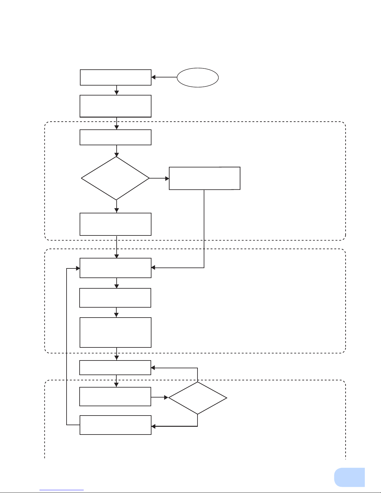
Procedure from installation to operation
Start
Installation/connection
Preparation for operation
Yes
No
No
Yes
Read “Safety precautions”
Page v
Remove the product from the
package and check the contents
Page 1
Perform installation and
connection Page 5
Check the operation and
displays Page 21
Charge the battery
Page 23
Measure the backup time
Page 34
Read “Using the UPS
monitoring software and
contact signal” Page 38
Operate Page 24
Deteriorated
battery?
Perform maintenance
and inspection Page 36
Replace the battery
Are you
using UPS monitoring
software or contact
signal?
Charge the battery again
Page 23
* Preparation for operation is
complete.
Maintenance/
inspection
Page 8

iv
Page 9

v
Table of Contents
Introduction .......................................................................................................................................... i
IMPORTANT SAFETY INSTRUCTION .............................................................................................. ii
Safety precautions ............................................................................................................................. vi
1. Preparation .................................................................................................................................... 1
1-1 Unpacking the product ......................................................................................................................... 1
1-2 Name of each part ...............................................................................................................................2
1-3 Explanation of symbols used on unit ...................................................................................................4
2. Installation and connection ............................................................................................................ 5
2-1 Precautions and notes on installation and connection .........................................................................5
2-2 Installation ............................................................................................................................................ 9
2-3 Connecting the equipment ................................................................................................................. 14
2-4 Connecting the AC input .................................................................................................................... 18
2-5 Checking the operation ...................................................................................................................... 21
2-6 Charging the battery ..........................................................................................................................23
2-7 Measuring the initial value of backup time ......................................................................................... 23
2-8 Recharging the battery ......................................................................................................................23
3. Operation ..................................................................................................................................... 25
3-1 Precautions and notes for operation .................................................................................................. 25
3-2 Start and stop procedures and basic operation ................................................................................. 27
3-3 Interpreting beeps and displays ......................................................................................................... 30
4. UPS functions ..............................................................................................................................31
4-1 Suspending a beep ............................................................................................................................ 31
4-2 Self-diagnosis test .............................................................................................................................31
4-3 Battery life counter function ...............................................................................................................32
4-4 Operation panel setting ......................................................................................................................32
5. Measuring the backup time ......................................................................................................... 35
5-1 How to measure backup time ............................................................................................................35
5-2 Estimated backup time ......................................................................................................................35
6. Maintenance and Inspection ....................................................................................................... 37
6-1 Checking the battery .......................................................................................................................... 37
6-2 Cleaning ............................................................................................................................................. 38
7. Using the UPS monitoring software and contact signal .............................................................. 39
7-1 When using the included UPS monitoring software to perform auto shutdown ................................. 41
7-2 Contact signal .................................................................................................................................... 43
8. Troubleshooting ...........................................................................................................................47
References .......................................................................................................................................49
A. Specications ......................................................................................................................................... 49
B. Dimensions ............................................................................................................................................. 50
C. Circuit block diagram .............................................................................................................................. 54
D. Related products .................................................................................................................................... 54
Page 10
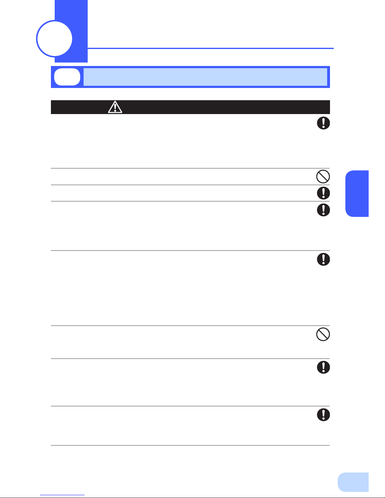
Safety precautions
vi
: Indicates prohibition. For example, indicates that disassembly is prohibited.
: Indicates obligation. For example,
indicates that grounding is necessary.
Misuse may cause death or serious injury.
Warning
Caution
Safety precautions
●
The safety symbols and their meaning used in this manual are as follows:
* Property damage means damage to houses/household effects, livestock, and pets.
Note that events categorized as a caution required matter also may cause more serious results under
certain conditions.
Do not use this unit when very high reliability and safety are required as
listed below. This unit is designed and manufactured for use with FA or
OA equipment such as personal computers.
●
Medical equipment or system that may cause death directly.
●
Applications that directly affect the safety of people (For example, the operation and control of
cars).
●
Applications in which a failure of the unit may cause signicant damage to the society and public
(For example, essential computer systems and main communication equipment.)
●
Applications with the same level of import
ance.
Warning
Important information for safe operation is described.
Be sure to read it before installation and start of use.
Misuse may cause injury or property damage.
Carry the unit considering its weight and balance, and place it on a stable
and robust base.
●
Dropping or toppling the unit may cause injury.
●
The approximate weights of the units are 28kg (BU2002RWLG), 33kg (BU3002RWLG) and 61kg
(BU5002RWLG).
●
If you drop the unit, stop using it and have it inspected and repaired.
For repair, contact Omron representatives.
Do not hold the side of the front panel when lifting.
●
Injury may result if the panel comes off and falls.
Keep plastic package bags out of reach of children.
●
Children may suffocate if they place their heads into plastic bags.
Make sure to connect the unit’s AC input plug to a commercial power
source with rated input voltage (200/208/220/230/240VAC) and 50/60 Hz
frequency.
●
Connecting to a commercial power source with a different rated input voltage or frequency may
result in a re.
●
The unit may fail.
Caution
(for installation and connection)
Page 11
BU75RW/BU100RW/BU200RWBU300RW
vii
For BU5002RWLG, when an abnormality (unusual sound or smell) occurs,
disconnect the AC input plug from the wall outlet, or turn OFF the INPUT
PROTECTION switch (input overcurrent protection switch) on the back of
the unit. The socket-outlet shall be installed near the equipment and shall
be easily accessible.
For BU2002RWLG and BU3002RWLG, turn OFF the external breaker
installed on the input side.
●
When performing maintenance on the connected devices, follow the above instructions to ensure
safety.
Do not connect devices such as dryers, some solenoid valves, etc., which
have a half-wave rectifier that allows only half-cycle AC power to flow
through.
●
Overcurrent may damage the UPS.
Connect the unit to a wall outlet (commercial power) with the
appropriate capacity (11A or greater for BU2002RWLG, 16A or greater for
BU3002RWLG and 27A or greater for BU5002RWLG).
●
Otherwise, the power cord may be heated.
●
When equipment with the maximum output capacity is connected, a maximum current of 11A
(BU2002RWLG), 16A (BU3002RWLG), or 27A (BU5002RWLG) ows.
When changing the input cable, make sure to perform the connection as
specied.
●
When connecting a cable to the terminal block, use a cable that complies with the input current
specication of the UPS.
●
Failure to do so may result in electric shock or ground fault.
When in use, make sure the output terminal block cover is attached. Do
not turn ON the power switch when it is detached.
●
Voltage is applied to the output terminal block when the power switch is ON, which can result in
electric shock.
Provide secure grounding.
●
For AC input plug connection, connect the plug directly to a commercial power source. For termi-
nal block connection, connect the cable to a commercial power source and ground it. A failure or
leak that occurs when the unit is not properly grounded may result in electric shock.
Do not disassemble, repair, or modify the unit.
●
Doing so may cause an electric shock or a re.
Do not install the unit in other than specied orientations.
●
Dropping or toppling the unit may cause injury.
●
If you install the unit in an orientation other than specied, the unit cannot be protected from a
battery uid leakage.
●
Use the included vertical stand when positioning the unit vertically.
Do not use the unit where the maximum temperature exceeds 40°C.
●
The battery deteriorates rapidly.
●
Doing so may cause a failure or malfunction of the unit.
Caution
(for installation and connection)
Page 12
Safety precautions
viii
Do not exceed the ranges specied for environmental conditions during
use/storage.
Do not install or store the unit in the places listed below.
●
Do not store in places where the humidity is lower than 10% or higher than 90%.
●
Do not use the unit in places where the ambient temperature is lower than 0°C or higher than
40°C. (With no condensation)
●
Do not use in places where the humidity is lower than 10% or higher than 90%.
●
Do not install/store the unit in closed places such as cabinets with no clearance, places where
there is ammable or corrosive gas, places with large amounts of dust, places exposed to direct
sunlight, places exposed to shock or vibration, salty or wet places, or outdoors.
●
Installation or storing the unit in such a place may cause a re.
Do not connect equipment that exceeds the output capacity of the unit.
You can use plug strip to connect additional devices, but do not connect
devices that exceed the current capacity of the plug strip.
●
The current protection of the unit may operate, which may stop the output.
●
The wiring of the plug strip heats up, which may cause a re.
Do not pinch or sharply bend the cable.
Do not fold or knot the cable.
●
Doing so may cause the cable to be damaged or heated, which may cause an electric shock or a re.
●
If the cable is damaged, stop using the unit and have the cable repaired.
●
For repair, contact Omron representatives.
All of the included accessories are designed to be used exclusively with
the unit. Do not use the accessories with other devices.
●
Doing so may compromise the safety of devices.
Do not block the air vents (front and rear).
●
Doing so will cause the internal temperature to rise, which may cause the unit to fail and the bat-
tery to deteriorate.
●
Leave at least 5 cm of space between the front vent and the wall, and at least 10 cm of space
between the rear vent and the wall.
Do not connect devices that cannot be used with commercial power
supply.
●
When the unit’s power switch is turned ON and an error occurs with the connected device, by-
pass operation is performed and commercial power supply is supplied as is to the connected
devices.
When installing the unit on a rack, place it on the lower shelf.
●
Injury may result if the unit falls.
Make sure to use the mounting screws included with the brackets.
●
Mounting screws other than those included may not be strong enough to support the unit, caus-
ing it to fall.
●
If you attach the case using long screws other than those included with the product, you may
damage the internal parts of the unit.
When using the unit in the 100V output mode, check that the output
voltage is set to 100V, and then turn ON the power switch.
●
Connecting a 100V device to the unit while outputting in the 200V mode may cause a failure of
the device or a re.
●
The output voltage can be set with “Settings” - “In/Out Settings” - “Output Voltage” in the menu
on the LCD.
Caution
(for installation and connection)
Page 13
BU75RW/BU100RW/BU200RWBU300RW
ix
Do not allow the unit to come in contact with water.
If you drop the unit, stop using it.
●
Doing so may cause an electric shock or a re.
●
If the unit becomes wet or is dropped, immediately stop using it, disconnect the AC input cable
from commercial power and have the unit inspected and repaired.
●
For repair, contact Omron representatives.
When the battery is dead, replace it immediately or stop using the unit.
●
Continuing the use of it may cause re or electric shock due to liquid leaks.
Using a dry cloth, periodically wipe the dust from the AC input plug, input
terminal block and power supply output receptacles.
●
Accumulated dust may cause a re.
Do not use the unit in a closed place and do not cover the unit.
●
Doing so may cause abnormal heating or a re.
●
Depending on the operating environment, hydrogen gas may be generated from the battery, re-
sulting in a rupture or explosion. Ventilate the area around the unit.
If you notice an abnormal sound or smell, smoke, or leaking fluid,
immediately turn OFF the unit's power switch and stop the supply of
commercial power.
●
Using the unit under such conditions may cause a re.
●
If you notice such a condition, stop using the unit and contact
Omron representatives.
for inspection
and repairs.
●
Position the unit in such a way that you can immediately disconnect the AC input plug from the
wall outlet (commercial power) in the event a problem occurs.
If uid leaks from the unit, do not touch the uid.
●
Doing so may cause blindness or burns.
●
If the uid contacts your eyes or skin, wash it out with lots of clean water and consult your doctor.
Do not place objects heavier than 25 kg on the unit, and do not drop
heavy objects onto the unit.
●
Doing so may cause distortion/damage to the case or a failure of the internal circuit, which may
cause a re.
The unit is equipped with a bypath circuit which is able to supply electric
power to connected devices even when the inner control circuit is broken
down by defects or malfunctions
●
Output is continuing even when all indicators of the front panel are off.
●
If you want to stop the output, either stop the source of commercial power or disconnect the AC
input plug from the wall outlet (commercial power).
Do not sit or stand on top of the product, use it as a step ladder, or lean
against it.
●
Doing so may cause the unit to fail or to fall over and result in injury.
* The values in the table are the expected life under stan-
dard use conditions and are not guaranteed.
Caution
(for use)
Ambient temperature Expected life
25°C 5 years
35°C 2.5 years
Page 14
Safety precautions
x
When maintaining the connected equipment, turn OFF the unit’s power
switch to stop the output, and stop the supply of commercial power.
●
Even if commercial power to the UPS is stopped while it is in operation, the power output of this
unit does not stop and power is supplied from the receptacle.
Do not disassemble, repair, or modify the unit.
●
Doing so may cause an electric shock or a re.
If uid leaks from the unit, do not touch the uid.
●
Doing so may cause blindness or burns.
●
If the uid contacts your eyes or skin, wash it out with lots of clean water and consult your doctor.
Do not throw the unit into re.
●
The lead battery in the unit may explode, or leak dilute sulfuric acid.
Do not insert metal objects into the power supply output receptacle of the
UPS.
●
Doing so may result in electric shock.
Do not insert metal objects into the battery connectors.
Do not create a short between the connector terminals.
●
Doing so may result in electric shock.
Perform replacement on a stable and at place.
●
Handle the battery carefully so that you do not drop it.
●
Not doing so could cause injury or burns due to liquid (acid) leakage.
Use a specied battery for replacement.
●
Not doing so may cause a re.
●
Replacement battery pack for
BU2002RWLG: BUB2002RWG
BU3002RWLG: BUB3002RWG
BU5002RWLG: BUB3002RWG (2PCS.)
Do not replace the battery in a place where there is ammable gas.
●
Spark may occur when connecting the battery, which may cause an explosion or re.
If uid (dilute sulfuric acid) leaks from the battery, do not touch the uid.
●
Doing so may cause blindness or burns.
●
If it contacts your eyes or skin, wash it out with lots of clean water and consult your doctor.
Do not disassemble or modify the battery.
●
Doing so could cause dilute sulfuric acid leak, which could cause blindness and burns.
Do not drop the battery and do not expose it to strong impact.
●
Dilute sulfuric acid may leak.
Do not short the battery with metal objects.
●
Doing so could cause an electric shock, re or burn.
●
Some electrical energy still remains inside the spent battery.
Do not put the battery into re and do not break it.
●
The battery may explode or leak dilute sulfuric acid.
Do not use a new battery and an old battery at the same time.
●
Dilute sulfuric acid may leak.
Caution
(for maintenance)
Caution
(for battery replacement)
Page 15

BU75RW/BU100RW/BU200RWBU300RW
xi
Notes
When moving the unit from a cold place to a warm place, leave it for several
hours before using it.
●
If the unit is promptly turned ON after being moved to a warmer place, condensation may form inside the
unit and cause it to fail.
Charge the battery soon after purchasing the unit.
●
If you do not use the unit for a long time after the purchase, the battery may deteriorate and the battery
may become unusable.
●
The battery can be charged once the AC input plug is connected to commercial power.
Recharge the battery for at least 8 hours every 6 months when the storage
temperature is 25°C or less, or every 2 months when the storage temperature is
40°C or less.
●
The battery self-discharges even when it not being used, and it goes into over-discharge state if it is left
for a long period of time. The backup time may become shorter or the battery may become unusable.
●
We recommend keeping the temperature 25°C or less when storing the unit for long periods of time.
●
Turn OFF the unit’s power switch when storing it.
Do not short the output lines of the unit to each other, and do not short the
output lines to the ground.
●
The unit may fail.
Do not connect the AC input terminal of the unit to its Power Supply Output
terminal during the Battery Mode.
●
The unit may fail.
Do not connect a page printer (such as a laser printer) to the unit.
●
The unit repeatedly and frequently switches between Commercial Power Mode and Battery Mode, which
may shorten the life of the battery.
●
The page printer has a large peak current, so an excess of the connection capacity or a power failure due
to instantaneous voltage drop may be detected.
Do not install or store the unit in a place exposed to direct sunlight.
●
The rise of temperature may cause the built-in battery to deteriorate rapidly and become unusable.
Do not perform withstand voltage tests.
●
Performing withstand voltage tests may damage the surge absorption element built into the power supply
input circuit.
●
When performing an insulation resistance test, use the 400 VDC range.
Before stopping the commercial power to the unit, turn OFF the power switch of
the unit.
●
The unit enters Battery Mode when commercial power is stopped. If you frequently use the unit in Battery
Mode, the battery life may be signicantly shortened.
If this unit is used for an inductive device such as a coil or motor, check the
operation beforehand.
●
With some types of devices, the effect of inrush current may cause this unit to stop operating properly.
Page 16
Safety precautions
xii
Explanation
Usual operation
●
You may either leave the power switch of the unit ON (operation status) or turn it OFF each time when
stopping the connected system. Choose whichever operation method is more convenient. We recommend
turning OFF the power switch when you do not use connected devices for a long time.
●
The battery can be charged once the unit is connected to a commercial power source.
Quitting Battery Mode
●
If a power failure lasts for an extended period of time, the battery discharges completely and power output
from the unit stops. Shut down your computer after performing appropriate procedures (for example, saving data) while the unit is still supplying power.
Rebooting
●
If the battery discharges completely during a power failure, the output stops. After recovery from the
power failure, the unit automatically restarts and output begins. If you do not want to restart the connected
devices, disable the “Settings” - “Boot Settings” - “Auto reboot” setting in the menu on the unit’s LCD, or
turn OFF the power switch of the connected devices.
Scheduled operation using the UPS monitoring software
●
When performing scheduled operation in which the UPS is stopped and a device such as a breaker is
used to stop the UPS at the same time that commercial power stops, specify a period of no more than 3
months for the start of the next operation.
If you specify a period longer than 3 months, the internal timer is reset and the scheduled operation does
not start. Note that this period reduces to approximately half when the battery needs to be replaced. If a
period of 3 months is exceeded, you start operation by supplying commercial power and pressing the start
switch. However, if the battery needs to be replaced, you may not be able to start operation.
In this case, replace the battery.
Pb
Notes
Check system operation beforehand if the unit is used in combination with a
device whose power supply voltage and frequency uctuate widely, such as a
generator.
●
If the generator’s output voltage/frequency falls out of the input voltage/frequency range, the unit will enter
Battery Mode.
●
Even if the input frequency is within the range, the unit will enter Battery Mode when a rapid change (5
Hz/sec or greater) occurs.
In the event you transfer or sell this unit to a third party, please include all of the
documentation that came with the unit. This is to ensure that the unit is used in
line with the conditions described in the included documentation.
●
This manual contains important safety-related information. Please read and understand the contents of
the manual before beginning operation.
This unit uses lead acid batteries,
●
Which are a valuable recyclable resource. Please recycle.
Take measures for handling unforeseen accidents, such as data backup and
system redundancy.
●
The output may stop when there is a circuit failure in the UPS.
Page 17
1
1
Open the package box and take out the UPS and accessories.
The approximate masses of the units are 28kg (BU2002RWLG), 33kg
(BU3002RWLG) and 61kg (BU5002RWLG) . Since the unit is heavy, be
careful not to hurt yourself when lifting or transporting it.
Hold the handle of the inner packaging when taking out the product
from the package box.
●
Hold the handle of the inner packaging when taking out the product from the package box.
●
Dropping may cause injury.
Caution
1-1
Unpacking the product
Preparation
1
Page 18
1.Preparation
2
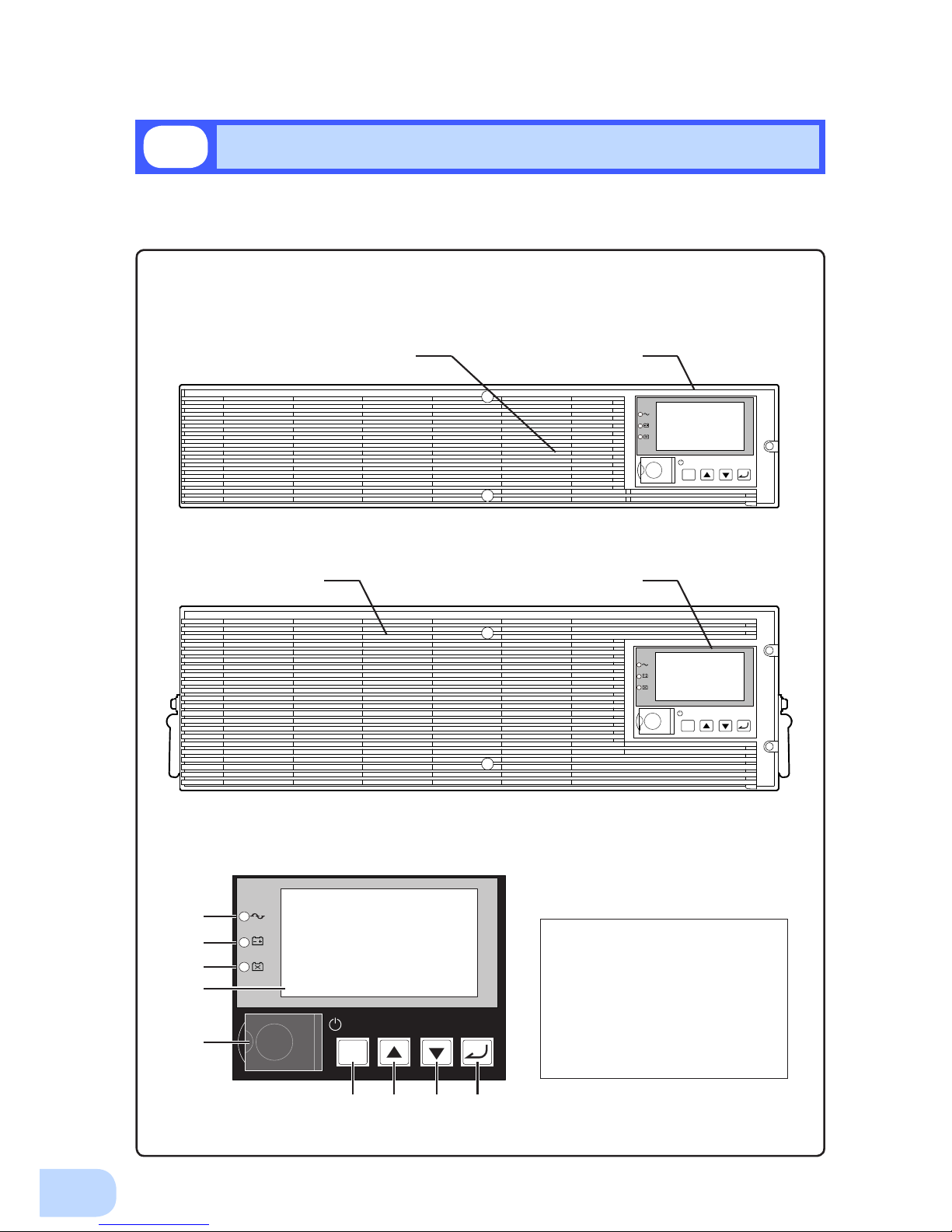
This section describes the name of each part of the UPS.
For information on the function of each part, refer to "2. Installation and connection" on page 5 and
"3. Operation" on page 24 that provides the details.
Front view
< Enlarged view of the operation panel >
A. Power supply output lamp
B. Battery mode lamp
C. Battery replacement lamp
D. LCD for status and setting display
E. Power switch
F. ESC switch
G. Up switch
H. Down switch
I. Enter switch
1-2
Name of each part
< BU2002RWLG/BU3002RWLG >
< BU5002RWLG >
ESC
<Air vent> <Operation panel>
ESC
ESC
A
B
C
D
E
F G H I
<Operation panel><Air vent>
Page 19
BU2002RWLG/BU3002RWLG/BU5002RWLG
1
3
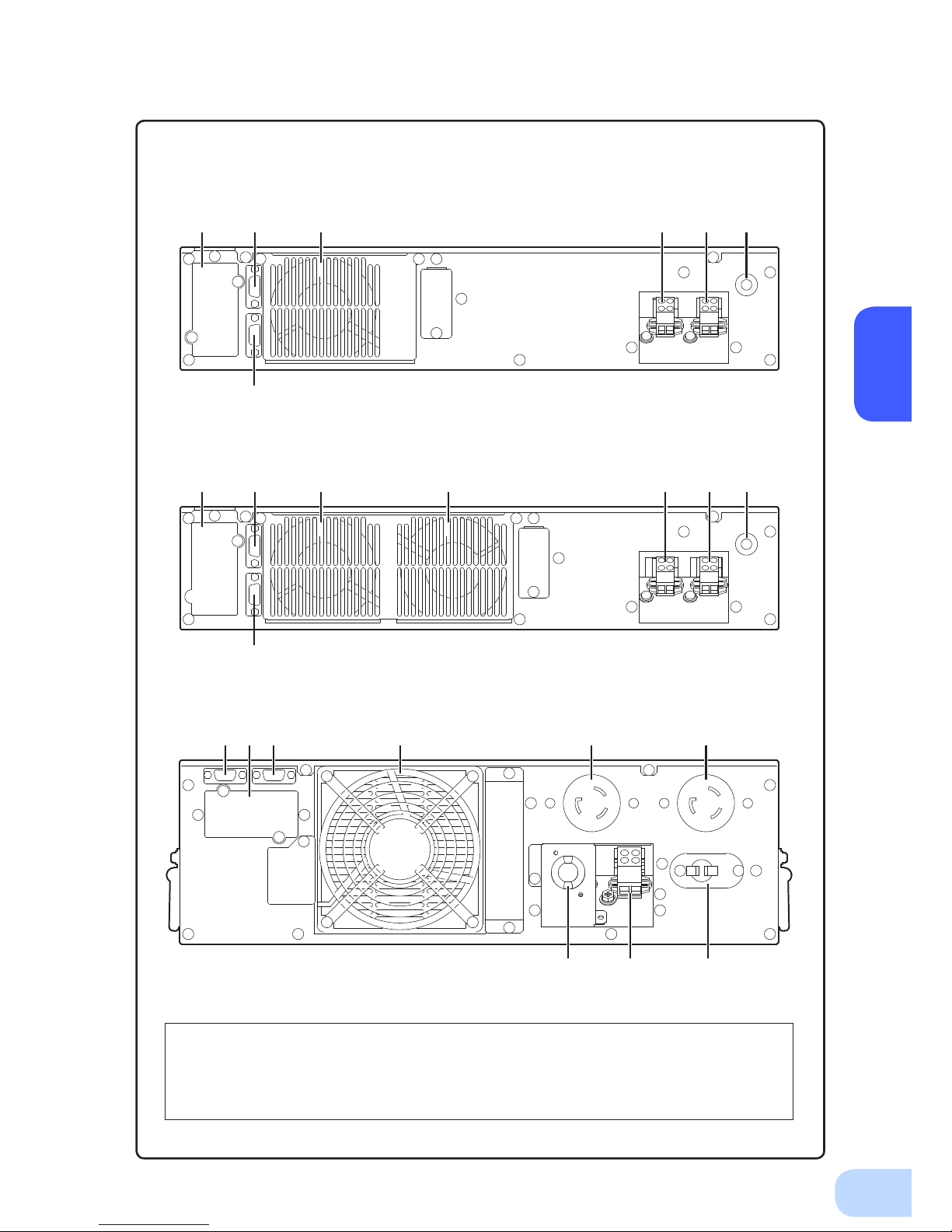
Rear view
A. Option slot
B. Contact signal port
C. RS-232C port
D. Cooling fan
E. AC input terminal block
F. AC output terminal block
G. AC input overcurrent protection switch
H. AC input cable
I. AC output receptacle
< BU2002RWLG >
< BU3002RWLG >
< BU5002RWLG >
A B D D E F G
C
A B D E F G
C
I IB
F G
A C D
H
Page 20
1.Preparation
4
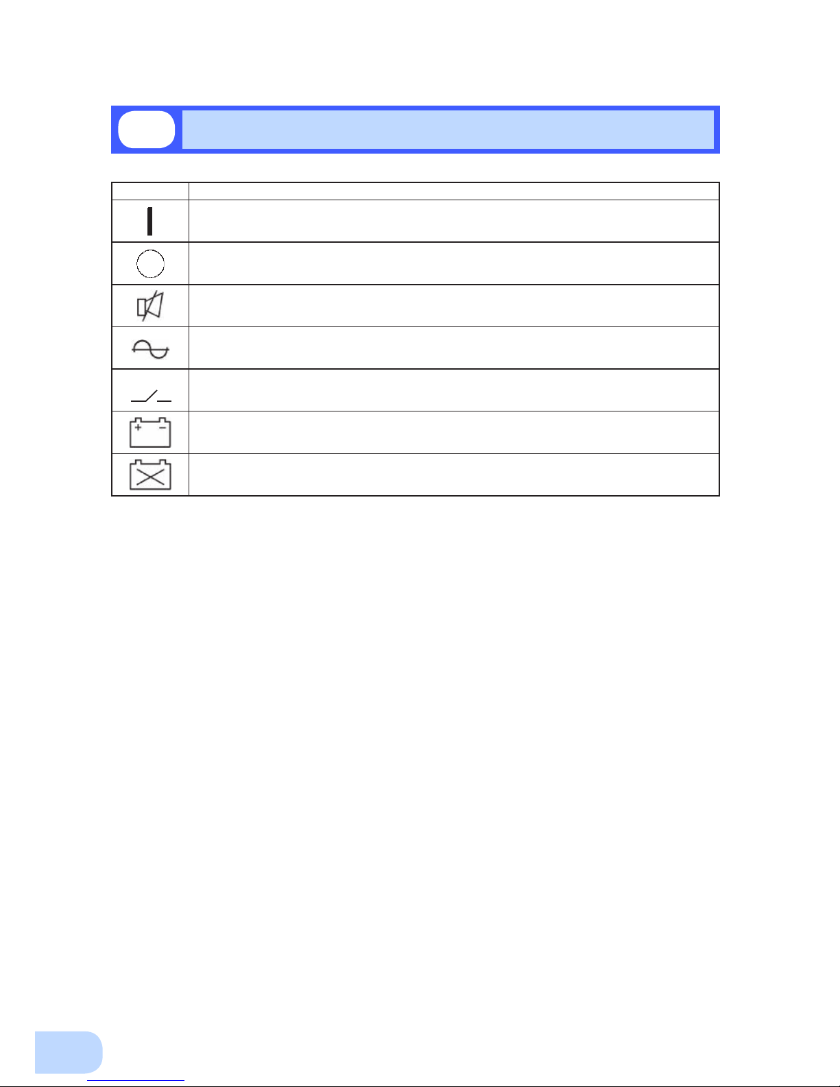
1-3
Explanation of symbols used on unit
Symbol Description
Start the UPS.
Stop the UPS.
Suspend a beep.
UPS output power enabled, supplied by operating on line mode, battery mode.
Bypass output “ON”.
UPS output power enabled, supplied by operating on battery mode.
Batteries at end of useful life, necessary to replace the batteries.
Page 21
2
5
Carry the unit considering its weight and balance, and place it on a stable
and robust base.
●
Dropping or toppling the unit may cause injury.
●
The approximate weights of the units are 28kg (BU2002RWLG), 33kg (BU3002RWLG) and 61kg
(BU5002RWLG).
●
If you drop the unit, stop using it and have it inspected and repaired.
For repair, contact Omron representatives.
Do not hold the side of the front panel when lifting.
●
Injury may result if the panel comes off and falls.
Keep plastic package bags out of reach of children.
●
Children may suffocate if they place their heads into plastic bags.
Make sure to connect the unit’s AC input plug to a commercial power
source with rated input voltage (200/208/220/230/240VAC) and 50/60Hz
frequency.
●
Connecting to a commercial power source with a different rated input voltage or frequency may
result in a re.
●
The unit may fail.
For BU5002RWLG, when an abnormality (unusual sound or smell) occurs,
disconnect the AC input plug from the wall outlet, or turn OFF the INPUT
PROTECTION switch (input overcurrent protection switch) on the back of
the unit. The socket-outlet shall be installed near the equipment and shall
be easily accessible.
For BU2002RWLG and BU3002RWLG, turn OFF the external breaker
installed on the input side.
●
When performing maintenance on the connected devices, follow the above instructions to
ensure safety.
Do not connect devices such as dryers, some solenoid valves, etc. ,
which have a half-wave rectier that allows only half-cycle AC power to
ow through.
●
Overcurrent may damage the UPS.
Connect the unit to a wall outlet (commercial power) with the
appropriate capacity (11A or greater for BU2002RWLG, 16A or greater for
BU3002RWLG and 27A or greater for BU5002RWLG).
●
Otherwise, the power cord may be heated.
●
When equipment with the maximum output capacity is connected, a maximum current of 11A
(BU2002RWLG), 16A (BU3002RWLG), or 27A (BU5002RWLG) ows.
When changing the input cable, make sure to perform the connection as
specied.
●
When connecting a cable to the terminal block, use a cable that complies with the input current
specication of the UPS.
●
Failure to do so may result in electric shock or ground fault.
2-1
Precautions and notes on installation and connection
Installation and connection
2
Caution
(for installation and connection)
Page 22
2.Installation and connection
6
When in use, make sure the output terminal block cover is attached. Do
not turn ON the power switch when it is detached.
●
Voltage is applied to the output terminal block when the power switch is ON, which can result in
electric shock.
Provide secure grounding.
●
For AC input plug connection, connect the plug directly to a commercial power source. For termi-
nal block connection, connect the cable to a commercial power source and ground it. A failure or
leak that occurs when the unit is not properly grounded may result in electric shock.
Do not disassemble, repair, or modify the unit.
●
Doing so may cause an electric shock or a re.
Do not install the unit in other than specied orientations.
●
Dropping or toppling the unit may cause injury.
●
If you install the unit in an orientation other than specied, the unit cannot be protected from a
battery uid leakage.
Do not use the unit where the maximum temperature exceeds 40°C.
●
The battery becomes weak rapidly, which may cause a re.
●
Doing so may cause a failure or malfunction of the unit.
Do not exceed the ranges specied for environmental conditions during
use/storage.
Do not install or store the unit in the places listed below.
●
Do not store in places where the humidity is lower than 10% or higher than 90%.
●
Do not use the unit in places where the ambient temperature is lower than 0°C or higher than
40°C. (With no condensation)
●
Do not use in places where the humidity is lower than 10% or higher than 90%.
●
Do not install/store the unit in closed places such as cabinets with no clearance, places where
there is ammable or corrosive gas, places with large amounts of dust, places exposed to direct
sunlight, places exposed to shock or vibration, salty or wet places, or outdoors.
●
Installation or storing the unit in such a place may cause a re.
Do not connect equipment that exceeds the output capacity of the unit.
You can use a plug strip to connect additional devices, but do not connect
devices that exceed the current capacity of the plug strip.
●
The current protection of the unit may operate, which may stop the output.
●
The wiring of the plug strip heats up, which may cause a re.
Do not pinch or sharply bend the cable.
Do not fold or knot the cable.
Doing so may cause the cable to be damaged or heated, which may cause
an electric shock or a re.
●
If the cable is damaged, stop using the unit and have the cable repaired.
For repair, contact Omron representatives.
The accessories are designed exclusively for use with this unit.
Do not use any of the included accessories with other devices.
●
Doing so may compromise the safety of devices.
Do not block the air vents (front and rear).
●
Doing so will cause the internal temperature to rise, which may cause the unit to fail and the bat-
tery to deteriorate.
●
Leave at least 5 cm of space between the front vent and the wall, and at least 10 cm of space
between the rear vent and the wall.
Caution
(for installation and connection)
Page 23

BU2002RWLG/BU3002RWLG/BU5002RWLG
2
7
Do not connect devices that cannot be used with commercial power
supply.
●
When the unit’s power switch is turned ON and an error occurs with the connected device, by-
pass operation is performed and commercial power supply is supplied as is to the connected
devices.
When installing the unit on a rack, place it on the lower shelf.
●
Injury may result if the unit falls.
Make sure to use the mounting screws included with the brackets.
●
Mounting screws other than those included may not be strong enough to support the unit, caus-
ing it to fall.
●
If you attach the case using long screws other than those included with the product, you may
damage the internal parts of the unit.
When using the unit in the 100V output mode, check that the output
voltage is set to 100V, and then turn ON the power switch.
●
Connecting a 100V device to the unit while outputting in the 200V mode may cause a failure of
the device or a re.
●
The output voltage can be set with “Settings” - “In/Out Settings” - “Output Voltage” in the menu
on the LCD.
Caution
(for installation and connection)
Page 24

2.Installation and connection
8
Notes
When moving the unit from a cold place to a warm place, leave it for several
hours before using it.
●
If the unit is promptly turned ON after being moved to a warmer place, condensation may form inside the
unit and cause it to fail.
Charge the battery soon after purchasing the unit.
●
The battery self-discharges even when it not being used, and it goes into over-discharge state if it is left
for a long period of time.
●
The battery can be charged once the AC input plug is connected to a commercial power source.
When storing the unit, charge the battery for at least 8 hours and turn OFF the
power switch.
●
Even if the unit is not used, the battery gradually discharges, and if it is left for a long time, it goes into an
over discharge state.
The backup time may become shorter or the battery may become unusable.
●
Connect the unit to a commercial power source for at least 12 hours every 6 months when the storage
temperature is 25°C or less, or every 2 months when the storage temperature is 40°C or less.
●
Turn off the power switch of the unit during storage.
Do not short the output lines of the unit to each other, and do not short the
output lines to the ground.
●
The unit may fail.
Do not connect the AC input plug of the unit to its Power Supply Output
Receptacle during the Battery Mode.
●
The unit may fail.
Do not connect a page printer (such as a laser printer) to the unit.
●
The unit repeatedly and frequently switches between Commercial Power Mode and Battery Mode, which
may shorten the life of the battery.
●
The page printer has a large peak current, so an excess of the connection capacity or a power failure due
to instantaneous voltage drop may be detected.
Do not install or store the unit in a place exposed to direct sunlight.
●
The rise of temperature may cause the built-in battery to deteriorate rapidly and become unusable.
Do not perform withstand voltage tests.
●
Performing withstand voltage tests may damage the surge absorption element built into the power supply
input circuit.
●
When performing an insulation resistance test, use the 400 VDC range.
Before stopping the commercial power to the unit, turn OFF the power switch of
the unit.
●
The unit enters Battery Mode when commercial power is stopped. If you frequently use the unit in Battery
Mode, the battery life may be signicantly shortened.
If this unit is used for an inductive device such as a coil or motor, check the
operation beforehand.
●
With some types of devices, the effect of inrush current may cause this unit to stop operating properly.
The battery contains dilute sulfuric acid which is a toxic substance. If uid leaks
from the battery, do not let it contact your skin or clothes. If contacted, wash
it out with clean water. In particular, if the uid gets in your eyes, immediately
wash them with clean water and seek medical treatment.
Check system operation beforehand if the unit is used in combination with a
device whose power supply voltage and frequency uctuate widely, such as a
generator.
●
If the generator’s output voltage/frequency falls out of the input voltage/frequency range, the unit will enter
Battery Mode.
●
Even if the input frequency is within the range, the unit will enter Battery Mode when a rapid change (5
Hz/sec or greater) occurs.
Page 25

BU2002RWLG/BU3002RWLG/BU5002RWLG
2
9
Do not use this unit in any position other than the “correct positions” indicated in the illustration below.
Note
Before installing this device, make a record of the serial number of this device.
The product serial number is required when contacting us about the device.
The serial number (S/N) is inscribed on the bottom left side of the rear panel.
The product serial number is inscribed on the bottom left side of the rear
panel. The product serial number label is also included.
2-2
Installation
Correct Positions
ESC
ESC
Be careful not to get your fingers caught
when arranging the unit.
(6&
(6&
,QFRUUHFW3RVLWLRQV
The UPS permits the following installing methods. Choose the one best suited for the environment.
2-2-1. Rackmount installation
2-2-2. Stationary installation
●
Horizontal
●
Upright intatllation
Page 26

2.Installation and connection
10
When performing rack installation, ensure that the UPS is supported and
stabilized by using both the support angles and the table clamps that
were included.
●
When installing on a rack, make sure that the UPS is supported by the each unit individually.
●
When installing on a rack, make sure to use the support angles and table clamps included with the
product. Without the support angles, the front clamp alone cannot support the weight of the UPS.
●
The mass of each unit: BU2002RWLG: Approx. 28kg BU3002RWLG: Approx. 33kg
BU5002RWLG: Approx. 61kg
In a case where the UPS is to be mounted on a rack, place it on the lower
part of the rack.
●
Dropping it may result in injury.
Be sure to use the supplied mounting screws.
●
Use of long screws other than those supplied for case mounting may damage inside the unit.
●
Screws other than those supplied may not be strong enough to support the UPS, causing it to fall.
2-2-1. Rackmount installation (EIA /JIS 19-inch rack/server rack)
●
Rack mounting procedure
(1) Insert the 2 included bracket mounting screws (M4) and half-tighten them to hold the front
and rear rack rails in place.
There are two types of front and rear rack rails: left (L) and right (R).
Caution
●
Items included in the 19-inch rack support angle mounting bracket set
Rack rail (front) L/R ........................................1 each
Rack rail (rear) L/R .........................................1 each
Unit guide rail L/R ..........................................1 each
Ear bracket L/R ..............................................1 each
Spacers .................................................................. 2
Bracket mounting screws (M4) ............................. 10
EIA/JIS rack fixing screws (M5) ........................... 10
EIA rack fixing nuts (M5) ...................................... 10
2 bracket fixing
screws (M4)
Page 27

BU2002RWLG/BU3002RWLG/BU5002RWLG
2
11
(3) For EIA standard-compliant installation, use the included EIA rack xing nuts (M5) and EIA/
JIS rack xing screws (M5) to securely fasten the front and the back of the rack rails to the
server rack. The screw hole positions are as follows.
• EIA rack : Topmost one for the front, topmost and bottommost ones for the rear
• JIS rack : One at the second from the bottom for both front and rear
(4) Use the 8 included bracket xing screws (M4) (2 sets of 4 screws) to securely fasten the ear
brackets and unit guide rails to the left and right sides of the UPS.
(Installation is possible without removing the handles on the sides of BU5002RWLG; do not
remove them.)
The support angles cannot be attached to special EIA/JIS racks.
(2) Adjust the length of support angles to suit the server rack, and then securely tighten the
screws that were half-tightened in step 1.
Rack fixing screws
Adjust the length to
suit the server rack
and tighten securely.
Page 28

2.Installation and connection
12
Always use the support angles.
(5) Place the UPS on the support angles and push it completely into the rack , and use the
included EIA/JIS rack xing screws (M5) and spacers to securely fasten the ear brackets to
the server rack. The screw hole positions are as follows.
• EIA rack : Topmost and bottommost ones on the front
• JIS rack : One at the second from the top on the front
Push completely in
Use the unit
fixing screws to
fasten
Note
The batteries for BU5002RWLG are in a separate package. Attach the batteries
to the unit before installation. For the attachment procedure, refer to "6-2
Replacing the battery".
Page 29

BU2002RWLG/BU3002RWLG/BU5002RWLG
2
13
2-2-2. Stationary installation
Perform installation only as shown in the diagrams below.
●
Horizontal installation
Attach the included rubber feet for horizontal installation with the included M3 screws and
position the unit horizontally.
For stationary horizontal installation, make sure that this product does not slide or fall.
(Installation is possible without removing the handles on the sides of BU5002RWLG; do not
remove them.)
●
Upright installation
(1) Upright installation
Use the upright stands included with the product.
Attach the two upright stands (front and back) for BU2002RWLG and BU3002RWLG, and
three (front, center, and back) for BU5002RWLG with the included screws.
Keep a space of 250 mm or more above the UPS.
(Installation is possible without removing the handles on the sides of BU5002RWLG; do not
remove them.)
ESC
ESC
Note
The batteries for BU5002 G are in a separate package. Attach the
batteries to the unit before installation. For the attachment procedure, refer to
"6-2 Replacing the battery".
Page 30

2.Installation and connection
14
2-3
Connecting the equipment
Caution
Do not connect devices with rated voltage of 200 to 240/100VAC or
higher.
●
The rated output voltage of this device is 200 to 240/100VAC.
●
Overcurrent may damage the connected devices.
PC server
NEMA L6-30P
(1) BU5002RWLG comes equipped with two “NEMA L6-30R” AC receptacles. Only devices with rated
voltage of 200 to 240 VAC can be connected to these AC receptacles. Connect devices with rated
voltage of 100 VAC to the AC output terminal block.
(2) Connect devices you want to back up to the Power Supply Output Receptacles of the UPS.
• If you need more output receptacles than those of the UPS, supply additional output receptacles.
2-3-1. Connecting a device to the power supply output
(AC receptacle) (BU5002RWLG only)
< Example of connection for BU5002RWLG >
Page 31

BU2002RWLG/BU3002RWLG/BU5002RWLG
2
15
Caution
2-3-2.
Connecting a device to the power supply output (AC output terminal block)
When in use, make sure the output terminal block cover is attached. Do
not turn ON the power switch when it is detached.
●
Voltage is applied to the output terminal block when the power switch is ON, which can result in
electric shock.
When connecting a device to the output terminal block, make sure to include
an emergency stop switch (ESD) between the unit and the load.
●
In the event of an accident, the power supply to the device can be stopped by pressing the emergency
stop switch.
●
To reduce the risk of re, connect only to an emergency stop switch (ESD) with a minimum rating of
250V/15A (BU2002RWLG), 250V/20A (BU3002RWLG), or 250V/30A (BU5002RWLG). When the unit is
used in compliance with UL standards or CE marking, follow the National Electrical Code (ANSI/NFPA 70).
●
Install the emergency stop switch where it is easy to operate.
ESD
daoLSPU
Emergency
Stop Switch
(1) Connect the devices that require backup to the power supply output terminal block of the unit.
Check that one terminal block cover and three M3 screws are included in the accessories.
BU2002RWLG and BU3002RWLG require two M3 screws, and BU5002RWLG requires one M3
screw. (The remaining M3 screws are spares.)
Run the wires to be connected through the hole in the terminal block cover (with cable clamp).
(See Figure 1.)
If you have trouble running the wire through the hole, loosen the cable clamp dial by turning it
counter-clockwise.
Crimp the specied round terminal to the ground wire, and tighten the ground terminal screw. (See
Figure 2.)
Use a at head screwdriver to loosen the terminal block screws, insert the wire stripped to the
specied length into the terminal block from the bottom at an angle as far as it will go, and then
retighten the terminal block screws. (See Figure 3.)
The wire connected to the G terminal should be longer than the wires connected to L1 and L2.
Refer to Table 1 for wire sizes.
G terminal : Connect the ground wire
L1 terminal : Connect the line
L2 terminal : Connect the neutral line
Page 32

2.Installation and connection
16
Table 1
BU2002RWLG
BU3002RWLG
BU5002RWLG
Connectable wire size 0.5 to 4mm
2
1.5 to 6mm
2
Amount of stripped wire 6 to 8mm 9 to 11mm
Tightening torque 0.49N•m 1.18N•m
Recommended cable size 2mm
2
(AWG14) 3.5mm2 (AWG12)
Figure 1
BU2002RWLG/BU3002RWLG
BU2002RWLG/BU3002RWLG
BU5002RWLG
BU5002RWLG
Figure 2
Figure 3
Crimp the round terminal to the ground wire.
BU2002RWLG/BU3002RWLG : For M4 screw
BU5002RWLG : For M5 screw
G
L2
L1
G
L2
L1
INPUT
G
L2
L1
G
L2
L1
INPUT
1
φ
170-278 VAC
50-60 Hz
15 A
OUTPUT
1
φ
100/
200/208/
220/230/240 VAC
50-60 Hz
15 A
OUTPUT1 25 A
Page 33

BU2002RWLG/BU3002RWLG/BU5002RWLG
2
17
When using the included UPS monitoring software or the contact signal, use the connection cable to
connect the unit to the PC.
2-3-3. Connecting to a computer
See also
“7. Using the UPS monitoring software and Contact Signal” on page 38.
* If you do not use the UPS monitoring software and Contact Signal, this step is not required.
(2) Attach the terminal block cover (with cable clamp) to the unit.For BU2002RWLG and BU3002R-
WLG, attach the cover after connecting the input cable.
BU2002RWLG/BU3002RWLG
Insert the upper part of the terminal block cover into the slit of the unit, and tighten it with two of
the included M3 screws.
Tighten the cable clamp dial to stabilize the wire.
G
L2
L1
G
L2
L1
INPUT
1
φ
170-278 VAC
50-60 Hz
15 A
OUTPUT
1
φ
100/
200/208/
220/230/240 VAC
50-60 Hz
15 A
BU5002RWLG
Insert the tab on the left side of the terminal block cover into the slit of the input terminal block cover, and then run one of the included M3 screws through the hole on the right side of the terminal
block cover and tighten it.
Tighten the cable clamp dial to stabilize the wire.
INPUT
G
L2
L1
G
L2
L1
OUTPUT1 25 A
Page 34

2.Installation and connection
18
2-4
Connecting the AC input
When installation and connection are complete, connect the unit’s AC input to a commercial power
source.
Make sure to connect the AC input plug of the unit into a wall outlet
(commercial power) with rated input voltage (200/208/220/230/240VAC).
●
Connecting to a wall outlet (commercial power) of a different rated voltage may result in re.
●
The unit may fail.
When the AC input power supply is grounded to the negative terminal,
make sure to use this unit's N terminal (phase) side as the ground (L2).
●
A misconnection may result in malfunction.
BU5002RWLG Input plug (NEMA L6-30P)
(Front view)
E
N L
Make sure to connect the input plug to a wall outlet equipped with a grounding
terminal.
●
Doing so may result in electric shock.
Caution
2-4-1. Connecting the AC input plug (BU5002RWLG)
●
Use the 15A plug included with the product at shipment.
Provide a wall outlet (commercial power) suitable for the shape of the 15A plug (NEMA 5-15R).
PC server
Power supply
200 VAC
External breaker
with 250 V/35 A.
(double pole)
Input
receptacle
Input
plug
●
The unit was charged before shipment, but it may have self-discharged during shipment,
resulting in a reduced backup time.
We recommend charging the unit before use.
●
You can perform "2-5 Checking the operation" on page 21 also before charging the battery.
Caution
(for installation and connection)
●
Provide a wall outlet (commercial power) compatible with the shape of the 30A plug (NEMA L6-30R).
< Example of connection for BU5002RWLG >
Page 35

BU2002RWLG/BU3002RWLG/BU5002RWLG
2
19
Caution
(for installation and connection)
2-4-2.
Connecting to the input terminal block (BU2002RWLG/BU3002RWLG/BU5002RWLG)
When connecting the AC input directly from a power switchboard, make
sure that the wiring work is performed by a qualied electrical engineer
(with Type II certication or higher).
●
To use the BU2002RWLG with up to 2000VA/1400W, a wiring capacity of 11 A or required.
●
To use the BU3002RWLG with up to 3000VA/2100W, a wiring capacity of 16A or required.
●
To use the BU5002RWLG with up to 5000VA/3500W, a wiring capacity of 27A or required.
Make sure to properly match the AC input terminal with the appropriate
wire color. Turn off the external breaker when performing work on the
unit's AC input terminals. Be sure to attach the AC input terminal block
cover.
●
Failure to do so may result in electric shock or ground fault.
Include a breaker (double pole) between the unit and the commercial
power, and install the breaker where it is easy to operate.
Connection procedure
(1) Remove the terminal-cover of the AC input terminal block.
(2) Run the wires through the terminal block cover (with cable clamp).
(3) Connect the ground wire to the G terminal. Use a at head screwdriver to loosen the terminal
block screw, insert the wire, and then retighten the screw.
(4) Connect the neutral line to L2, and connect the line to L1.
Connections to the terminal block shall comply with the standards in Table 1.
(5) Fix the terminal block cover with the screws, and then turn the clamp to stabilize the wires.
Table 1
BU2002RWLG
BU3002RWLG
BU5002RWLG
Connectable wire size 0.5 to 4mm
2
1.5 to 6mm
2
Amount of stripped wire 6 to 8mm 9 to 11mm
Tightening torque 0.49N•m 1.18N•m
Recommended cable size 2mm
2
(AWG14) 3.5mm2 (AWG12)
Page 36

2.Installation and connection
20
(Example of connection)
Load
Power supply
200 VAC
External breaker
with 250 V/20 A.
(double pole)
Emergency Stop
Switch
●
The unit was charged before shipment, but it may have self-discharged during shipment,
resulting in a reduced backup time.
We recommend charging the unit before use.
●
You can perform "2-5 Checking the operation" on page 21 also before charging the battery.
<BU2002RWLG/BU3002RWLG>
<BU5002RWLG>
Load
Power supply
200 VAC
External breaker
with 250 V/35 A.
(double pole)
Emergency Stop
Switch
Page 37

BU2002RWLG/BU3002RWLG/BU5002RWLG
2
21
When you nish connecting the unit, conrm that the backup operation works properly.
Check that the Battery Mode is performed normally according to the following procedure.
(In this operation check, the effects of a power failure are reproduced by disconnecting the AC input
plug from the wall outlet (commercial power).)
(1) Press and hold the unit’s power switch for 3 seconds or longer to turn ON the power.
The beeper sounds and the current settings are displayed on the LED.
Self-diagnosis starts automatically.
When the self-diagnosis test nishes normally, the unit’s operation switches to commercial power
and the status indication below is displayed.
(2) Bring all the connected devices into operation.
(Including devices connected to the AC outlet of your PC.)
The unit was charged before shipment, but it may have self-
discharged during shipment, resulting in a reduced backup
time. We recommend charging the unit before use.
(3) Under this condition, check the the unit's LCD and beep sound.
Are they in the same status as shown below?
Status indicator
Beep None
Power supply output receptacles Outputs power (connected devices are powered)
If the same as the one shown above:
→ The operation is normal. Proceed to (4).
If not the same as the one shown above:
→ The operation is abnormal. One of the cases described in
"4. Display and beeps when there is an equipment failure"
of "3-3 Interpreting beeps and displays" on page 29 must
apply.
Take necessary measures and then proceed to (4).
(4) Disconnect the unit’s AC input plug from the wall outlet (commercial power). When the AC
input cable is connected to the terminal block, turn off the external breaker.
The unit enters Battery Mode.
2-5
Checking the operation
Status indicator Description
Power switch “ON”
Operating normally
ON OFF
ON, OFF, or blinking
depending on status
ESC
Page 38

2.Installation and connection
22
(5) In Battery Mode, check the unit's LED display and beep sound.
Does the status indicator appear as one of those shown below?
If not the same as one of those shown above:
→ Operation is abnormal. Check the status of lamps and
beep, and then press and hold the power switch for 3 seconds or longer to turn OFF the power.
• If the display is one of those shown in “4. Displays and
beeps when there is an equipment failure” in “3-3 Interpreting beeps and displays” on page 29, take the necessary measures and then go back to (1) on page 21.
• If no Battery Mode is performed and the UPS and the
devices connected to the UPS stop, this may be attrib-
uted to an insufcient battery charge.
After connecting the AC input plug to a wall outlet (com-
mercial power) and charging the battery, go back to step
(4) on page 21.
• If the problem persists after checking the 2 points above,
contact
Omron representatives.
See also
Beeper ON/OFF can be set with “Settings” - “Local Setting” - “Audible alarm” in the
menu on the LCD.
(6) Reconnect the AC input plug to the commercial power source. When the AC input cable is
connected to the terminal block, turn on the external breaker.
The status indicator returns to its normal state and the beeping sound stops.
(The status is as shown below.)
Checking the operation is now complete.
Installation and connection is now complete.
Status indicator Beep Output Description
Intermittent
4-second
intervals
ON
Backup is operating due to power failure or AC input error. Output will
stop if Battery Mode continues.
Intermittent
1-second
intervals
ON
(Same as above.)
Battery level is low, so output will stop soon.
None OFF Battery is dead, so output stopped.
Status indicator Description
Power switch “ON”
Operating normally
Page 39

BU2002RWLG/BU3002RWLG/BU5002RWLG
2
23
The battery automatically starts charging when the unit is connected to a commercial power
source.
(This occurs regardless of whether the power switch is ON or OFF.)
The charging takes 8 hours to complete.
●
The unit was charged before shipment, but it may have self-discharged during shipment, resulting
in a reduced backup time. We recommend charging the unit before use.
●
If you do not perform the initial backup time measurement described below in “2-7 Measuring the
initial value of backup time”, proceed to “3. Operation. → Page 24”
●
When you measure the backup time initial value of the unit in your environment, this value can
be used as a guide when checking the battery and deciding the UPS monitoring software setting
values.
See also
"5. Measuring the backup time" → Page 34
The battery is discharged completely when the backup time is measured, so you need to recharge it
before using the UPS.
●
You can use connected devices while recharging the battery, but the backup time when a power
failure occurs is shorter until the battery is fully charged.
(If a power failure occurs immediately after the start of charging, backup stops immediately.)
See also
Charge the battery as described in "2-6 Charging the battery."
Preparation for starting operation is now complete.
2-6
Charging the battery
2-8
Recharging the battery
2-7
Measuring the initial value of backup time
Page 40

24
Page 41

3
25
3-1
Precautions and notes for operation
Operation
3
Do not allow the unit to come in contact with water. Do not drop the unit.
●
Doing so may cause an electric shock or a re.
●
If the unit becomes wet, immediately stop using it, disconnect the AC input cable from commer-
cial power and have the unit inspected and repaired.
For repair, contact Omron representatives.
When the battery is dead, replace it immediately or stop using the unit.
●
Continuing the use of it may cause re or electric shock due to liquid leaks..
Using a dry cloth, periodically wipe the dust from the AC input plug and
power supply output receptacles.
●
Accumulated dust may cause a re.
Do not use the unit in a closed place and do not cover the unit.
●
Doing so may cause abnormal heating or a re.
If you notice an abnormal sound or smell, smoke, or leaking uid,
immediately turn OFF the unit’s power switch and stop the supply of
commercial power.
●
Using the unit under such conditions may cause a re.
●
If you notice such a condition, stop using the unit and contact
Omron representatives
for inspection
and repairs.
●
Position the unit in such a way that you can immediately disconnect the AC input plug from the
wall outlet (commercial power) in the event a problem occurs.
If uid leaks from the unit, do not touch the uid.
●
Doing so may cause blindness or burns.
●
If the uid contacts your eyes or skin, wash it out with lots of clean water and consult your doctor.
Do not place objects heavier than 25kg on the unit, and do not drop heavy
objects onto the unit.
●
Doing so may cause distortion/damage to the case or a failure of the internal circuit, which may
cause a re.
The unit is equipped with a bypath circuit which is able to supply electric
power to connected devices even when the inner control circuit is broken
down by defects or malfunctions
●
Output is continuing even when all indicators of the front panel are off.
●
If you want to stop the output, either stop the source of commercial power, or disconnect the AC
input plug from the wall outlet (commercial power).
Do not sit or stand on top of the product, use it as a step ladder, or lean
against it.
●
Doing so may cause the unit to fail or to fall over and result in injury.
Caution
(for use)
Take notice of following items during operation.
Ambient temperature Expected life
25°C 5 years
35°C 2.5 years
* The values in the table are the expected life under standard
use conditions and are not guaranteed.
Page 42

3.Operation
26
Explanation
Usual operation
●
You may either leave the power switch of the unit ON (operation status) or turn it OFF each time when
stopping the connected system. Choose whichever operation method is more convenient. We recommend turning OFF the power switch when you do not use connected devices for a long time.
●
The battery can be charged once the AC input plug is connected to commercial power.
Quitting Battery Mode
●
If a power failure lasts for an extended period of time, the battery discharges and power output from the
unit stops. Shut down your computer after performing appropriate procedures (for example, saving data)
while the unit is still supplying power.
Rebooting
●
If the battery discharges completely during a power failure, the unit stops. After recovery from the power
failure, the unit automatically restarts and supplies power. If you do not want to restart the connected devices, disable the “Settings” - “Boot Settings” - “Auto reboot” setting in the menu on the unit’s LCD, or turn
OFF the power switch of the connected devices.
Scheduled operation using the UPS monitoring software
●
When performing scheduled operation in which the UPS is stopped and a device such as a breaker is
used to stop the UPS at the same time that commercial power stops, specify a period of no more than 3
months for the start of the next operation. If you specify a period longer than 3 months, the internal timer
is reset and the scheduled operation does not start.
Note that this period reduces to less than half when the battery needs to be replaced.
If a period of 3 months is exceeded, you start operation by supplying commercial power and pressing the
Start Switch. However, if the battery needs to be replaced, you may not be able to start operation. In this
case, replace the battery.
Notes
Before stopping the commercial power to the unit, turn OFF the power switch of the unit.
●
The unit enters Battery Mode when commercial power is stopped. If you frequently use the unit in Battery
Mode, the battery life may be signicantly shortened.
Take measures for handling unforeseen accidents, such as data backup
and system redundancy.
●
The output may stop when there is a circuit failure in the UPS.
Page 43

BU2002RWLG/BU3002RWLG/BU5002RWLG
3
27
3-2
Start and stop procedures and basic operation
The UPS status indicators and UPS setting change menu are displayed on the control display panel
on the front of the unit.
●
UPS status indicators (status screen)
Status indicator
Load level
Battery level
Upper text
Lower text
Backup time
Output setting
●
UPS setting change menu screen
Cursor
Menu list
Menu title
Previous/next
page mark
Basic operations on the menu screen
Switch Description
[▲] [▼] Move cursor up/down or increase/decrease values
[
] Selection of menu or determine the value
[ESC] Return to menu or cancel
Page 44

3.Operation
28
• During operation, the battery is charged automatically.
●
When the unit is connected to a commercial power source with the power
switch OFF and commercial power is supplied to it
• The status indicator displays " ".
• Power output is stopped.
• The battery automatically starts recharging.
• The standby screen appears on the LCD.
●
Start procedure
Press and hold the power switch of the UPS for 3 seconds or longer.
• After a few seconds, output begins in inverter operation.
• The status indicator displays “
“, and the self-diagnostic test is performed.
• When the self-diagnosis test finishes normally, the unit enters the normal operating state
through inverter operation.
• When the self-diagnostic test is not performed, AC output begins immediately inverter
operation.
Operation
Status
indicator
Beep Output Description Solution
None ON Commercial Power Mode
-
Page 45

BU2002RWLG/BU3002RWLG/BU5002RWLG
3
29
●
Operation after a power failure
• If a power failure or abnormal input power supply occurs, the UPS automatically switches to
Battery Mode, continuing power output from the Power Supply Output terminal block supplied
from the battery.
• The LCD and the beeper’s intermittent sounds alert the user.
See also
“Local Settings” in the menu on the LCD can be used to set the beeper ON/OFF.
Status
indicator
Beep Output Description Solution
Intermittent
4-second
intervals
ON
Backup is operating due to power
failure or AC input error.
Shut down the connected devices to
stop them.
Intermittent
1-second
intervals
ON
Battery level is low, so output will stop
soon.
Intermittent
2-second
intervals
OFF Battery is dead, so output stopped. Charge the battery.
●
Operation during recovery from a power failure
• The unit automatically resumes output via commercial power if it recovers from a pow er
failure/input power supply error while it is providing power supply output. The spent battery
starts charging.
• If a power failure or abnormal power input is resolved after the battery is discharged completely
and power output is stopped, the UPS restarts automatically and resumes power output. The
expended battery begins to charge.
See also
“Boot Settings” in the menu on the LCD can be used to enable or disable auto restart.
●
Stop procedure
Operation
Press and hold the power switch of the UPS for 3 seconds or longer.
• The power output from the UPS stops.
• Even if you turn off the power switch, if AC is supplied from commercial power, the battery is
automatically charged.
Status
indicator
Beep Output Charging Description
None OFF ON Power switch OFF
Page 46

3.Operation
30
3-3
Interpreting beeps and displays
No.
Status
indicator
Mode Beep Description Solution
1
Standby
Mode
None Power switch OFF
Operation stopped
-
2
Commercial
Power Mode
None Power switch ON
Operating normally
-
3
Bypass
Mode
None AC input is bypassed to the
output due to an internal failure
of the UPS or other reason
Refer to the message
displayed on the LCD.
4
Test Mode None Self-diagnostic test in progress Commercial Power Mode
is recovered after a
certain period of time.
5
UPS Event None Waiting; startup conditions are
not fullled
Refer to the displayed
message.
6
Battery
Mode
Intermittent
4-second
Backup is operating due to
power failure or AC input error
Shut down the connected
devices to stop them.
7
Battery Low Intermittent
1-second
Battery level is low, so output
will stop soon
Shut down the connected
devices to stop them.
Battery
Empty
Intermittent
2-second
Battery is dead, so output
stopped
Charge the battery.
8
Battery
Deterioration
Intermittent
2-second
Battery has deteriorated Replace the battery.
9
Overload Intermittent
0.5-second
High connection load Reduce the connection
load.
10
UPS Failure Continuous Failure or warning has
occurred
Refer to the message
displayed on the LCD.
●
Load/battery level meter
The load level meter displays the power consumption of the connected devices as a percentage.
BU2002RWLG: Displayed in 10 levels, with 100% indicating 2000 VA/1400 W.
BU3002RWLG: Displayed in 10 levels, with 100% indicating 3000 VA/2100 W.
BU5002RWLG: Displayed in 10 levels, with 100% indicating 5000 VA/3500 W.
The battery level meter displays the remaining battery level as a percentage.
Page 47

4
31
This test performs a failure diagnosis on the unit and performs a test to check for battery deterioration.
Use the procedure below to check whether a circuit failure has occurred inside the unit and whether
battery replacement is required.
This test is performed if the “Power” switch is ON or performed automatically (You do not have to
perform any special operations). Automatic test is performed once every 4 weeks after the unit is connected to a commercial power source and power distribution begins.
If the battery is not charged for at least 24 hours, the self-diagnostic test is not executed immediately.
After charging is complete, it is automatically executed.
(1) When the self-diagnostic test is executed, the Battery Mode starts automatically (No beep
sounds). After the test is complete, the normal operation automatically starts.
(2) If an error message appears on the LCD:
Follow the directions for the solutions described earlier in this document.
* This test can also be run from the included UPS monitoring software.
For more details, refer to the online help for the UPS monitoring software.
When the beep is sounding, you can suspend it by pressing and
holding the beep ESC switch for 0.5 seconds or longer.
4-1
Suspending a beep
UPS functions
4
4-2
Self-diagnosis test
ESC
Page 48

4. UPS functions
32
This function noties you with LCD and beep sound when the battery needs to be replaced. The battery life counter operates while commercial power is supplied after shipment. (When the ambient
temperature of the battery is higher than 25°C, the value of the counter will be incremented at a faster
pace.)
When the battery needs to be replaced, the battery replacement lamp will light up and beep will sound.
* Be sure to reset the battery life counter after replacing the battery.
4-3
Battery life counter function
4-4
Operation panel setting
A list of menu items on the LCD is shown in the table below. Menu items displayed vary depending on
the menu type setting.
The menu type can be set with “Settings” - “Local Settings” - “Menu Type”. There are two types of
menu: “Standard Mode” (for general users) and “Advanced Mode” (for administrators).
<Meaning of the Note column>
*1: Displayed only when the menu type is “Advanced Mode”. (Not displayed in “Standard Mode”.)
*2: The setting can be changed only when the UPS is stopped. During operation, the setting can be
checked but not changed.
Menu Description Note
Measurements Load Meter Display the applied load in VA and W.
Input/Output Display the input/output voltage and
frequency.
Battery Meter Display the status of the built-in battery.
Longevity Display the estimated lifespan of the
UPS in 5 levels.
Efciency Display the efciency of the UPS as a
percentage.
*1
Cumulat. Power Display the amount of power used so
far and the number of days elapsed.
*1
Average Power Display the average amount of power
used so far.
*1
Control Function Test Perform a self-diagnosis and a test to
check for battery deterioration, and
then display the results.
ResetB.L.cnt Reset the battery life counter.
Reset Failure Reset a failure.
ResetPow.Usage Reset the values of cumulative power
usage and average power usage.
*1
DryContactTest Perform a contact signal test. *1
*2
Maintenance Move to Bypass Mode forcibly. *1
Initialization Return each of the UPS settings to the
factory settings.
*1
*2
Page 49

BU2002RWLG/BU3002RWLG/BU5002RWLG
4
33
Menu Description Note
Settings Local Settings Language Set the language to be displayed on
the LCD.
LCD Setting Change the contrast of the LCD.
LCD Auto off Set the amount of time after which the
LCD turns off automatically.
LCD Test Check that the LCD and LEDs light up.
Audible alarm Set the beeper status.
Calendar Set the calendar information for the
UPS.
UPS Inst. Date Set the date you started using the UPS.
UPS life count Set the UPS life counter status.
Menu Type Select the menu to be displayed.
"Standard" displays frequently used
items only.
In/Out Settings Output Voltage Set the output voltage.
* When this product is used in
compliance with UL standards, do not
set 100V output mode.
*2
Frequency Range Switch the frequency range mode. *1
Boot Settings Auto reboot Set auto restart from power failure.
Delay time Set the delay time for recovery from
power failure.
*1
Battery level Set the battery voltage for restarting the
UPS.
*1
Reboot Mode Set the mode for rebooting. *1
Power SW off Switch the operating mode of the power
switch.
*1
Batt. Settings Function Test Set the timing at which to execute the
self-diagnostic test.
Bat.L.Counter Set whether to be notied of the battery
life.
Bat.Inst.Date Set the date you replaced the battery.
Max.BackUpTime Set the output of the UPS to stop after
a specied amount of time.
*1
Low Battery Set the level at which to detect low
battery.
*1
Settings Dry Contact BS Valid Range Set the status for receiving the BS
signal.
*1
BS Delay Time Set the delay time for the BS signal. *1
*2
BU Delay Time Set the delay time for the BU signal. *1
DryCont. Logic Set the logic of each contact signal. *1
Remote Logic Set the logic of the remote signal. *1
Page 50

4. UPS functions
34
Menu Description Note
Identication Type Display the names of the UPS and
battery pack.
Serial Number Display the serial number of the UPS.
Firmware Ver. Display the rmware version of the
UPS.
*1
Memorandum You can record information of 20
alphanumeric characters.
*1
Log Fault Log Display up to 10 fault log records (time
of occurrence and details of each
failure).
*1
Shutdown log Display up to 10 reasons for shutdown
of the UPS.
*1
Event Log Display up to 10 event log records. *1
Reset all log Clear each log. *1
Page 51

5
35
(1) Convert the total capacity (power consumption) of the connected devices to watts (W).
For the indication of connected devices, check your computer and the rear of the display.
The indicator can show values in three different ways: volt-amperes (VA), amperes (A), and watts
(W).
Example 1) 200 VAC, 50/60Hz, 145 W
Example 2) 200 VAC, 50/60Hz, 1.8 A
Example 3) 200 VAC, 50/60Hz, 150 VA
For devices that use the VA or A indication, convert the capacity into W. Multiply the value indi-
cated on devices by the value in the right table for conversion.
(When the power factor is unknown, enter “1”. The power factor usually ranges between 0.6 and 1.)
(2) Add the values converted into W to obtain the total capacity of the connected devices.
(3) Calculate the initial value of the backup time for the total capacity of the connected devices from
the graph below.
●
Graph of backup time (graph of initial values for products that have not been used at 25°C)
The backup time becomes shorter than the graph (table) below when temperature is lower.
●
The smaller the capacity of connected devices becomes, the longer the backup time becomes.
Indication Value
VA
×
power factor = W
A
×
power factor × power supply voltage = W
(1) Connect to commercial power and charge the battery for 8 hours (Charging time is extended 24
hours per unit, if additional battery unit is connected).
(2) Turn ON all devices connected to the unit.
(3) Turn off the commercial power and measure the backup time.
In Battery Mode, measure the time until the unit automatically stops and all displays disappear.
The power supply output of the unit will stop when the battery discharges. Conduct
measurement under a condition in which no problem occurs even if the power supply of the
connected device stops during the process. Do not conduct measurement if there is a
possibility of a failure when the power supply stops.
5-1
How to measure backup time
Measuring the backup time
5
5-2
Estimated backup time
The backup time you measure for the rst time after purchase is the “initial value of the backup time.”
You can precisely judge the deterioration condition of the battery if you measure the “initial value of the
backup time” in advance at the time of a battery check.
Page 52

5. Measuring the backup time
36
BU5002RWLG
BU3002RWLG
0
20
40
60
80
100
120
140
160
0 500 1000 1500 2000 2500 3000 3500
Backup time (Minutes)
Connection capacity (W)
Backup time (25°C, initial value)
BU2002RWLG
* These backup times are for reference only. Times may vary according to battery life and external environmental
conditions (temperature, etc.).
Backup time table Time unit: (Minutes)
BU2002RWLG
Connection
capacity (W)
20 50 100 200 300 400 600 800
1000 1200 1400
Backup time
(Minutes)
360 190 110 60 39 27 16 12 9.5 7 5
BU3002RWLG
Connection
capacity (W)
20 50 100 200 300 400 600 800
1000 1200 1400 1600 1800 2000 2100
Backup time
(Minutes)
450 260 165 93 63 45 28 19 15 11 9 7.5 6 5.2 5
BU5002RWLG
Connection
capacity (W)
20 50 100 200 300 400 600 800
1000 1200 1400 1600 1800 2000 2100 2700 3000 3500
Backup time
(Minutes)
660 480 320 200 140 106 68 50 39 31 25 21 18 16 15 10 8 5
Page 53

6
37
The lead battery used in the unit has a limited lifespan.
(The life varies depending on your storage/use environment and backup frequency.)
The nearer the end of the life is, the more rapidly deterioration proceeds.
1. Battery life expectancy (* Not a guaranteed performance)
2. Methods for checking the battery
There are two methods for checking the battery.
• Perform a self-diagnostic test. (See page 30.)
• Measure the backup time. (See page 34.)
By measuring the backup time, the battery life can be determined more accurately.
• When you compare the "initial value of the backup time" you measured and the current
backup time, make the capacity of devices connected to the UPS same as when you measured the initial value to make judgment accurately.
When maintaining the connected equipment, turn OFF the unit’s power
switch to stop the output, and stop the supply of commercial power.
●
Even if commercial power to the UPS is stopped while it is in operation, the power output of this
unit does not stop and power is supplied from the receptacle.
Do not disassemble, repair, or modify the unit.
●
Doing so may cause an electric shock or a re.
If uid leaks from the unit, do not touch the uid.
●
Doing so may cause blindness or burns.
●
If the uid contacts your eyes or skin, wash it out with lots of clean water and consult your doctor.
Do not throw the unit into re.
●
The lead battery in the unit may explode, or leak dilute sulfuric acid.
Do not insert metal objects into the power supply output receptacles of the UPS.
●
Doing so may result in electric shock.
Do not insert metal objects into the battery connectors.
Do not create a short between the connector terminals.
●
Doing so may cause an electric shock.
6-1
Checking the battery
Maintenance and Inspection
6
Caution
(for maintenance)
Ambient temperature Battery life expectancy
25°C 5 years
35°C 2.5 years
Page 54

6. Maintenance and Inspection
38
3. Guidelines for how often to check the battery (measure the backup time)
* The battery deteriorates even if it is stored. The higher the temperature is, the shorter
the life becomes.
Average ambient
temperature
6-month check
Monthly check
25°C
For the rst 4 years after starting use When 4 years or more have passed after starting use
35°C
For the rst 2 years after starting use When 2 years or more have passed after starting use
1. Cleaning the UPS
Moisten a soft cloth with water or detergent, squeeze it tightly, and wipe the product lightly.
Do not use chemicals such as thinner and benzene. (They cause deformation or discoloration.)
2. Removing dust from the AC input plug, power supply output receptacles,
input terminal block, and output terminal block of the UPS
Stop all the connected devices and the UPS and disconnect the AC input plug from a wall outlet
(commercial power).
Then, remove dust with a dry cloth and make the connection again.
(For information on the connection procedure:)
See also
"2-3 Connecting the equipment" → Page 14
6-2
Cleaning
Page 55

BU2002RWLG/BU3002RWLG /BU5002RWLG
7
39
Using the UPS monitoring software
and contact signal
7
■
UPS monitoring software
“PowerAct Pro” and “Simple Shutdown Software” is included with this product. Refer to the table below
for details about compatibility. Choose which one to use based on the application. Refer to the table
below for details about compatibility. For further details about the software functions, refer to the separate "UPS Monitoring Software Quick Installation Guide."
* If you do not use the UPS monitoring software and contact signal, this
step is not required.
• UPS monitoring software selection table
OS Communication method UPS monitoring software
Required options
(sold separately)
Reference
Windows 8
Windows 7
Windows Vista
Windows Server2012
Windows Server2008
(including R2)
Windows Storage Ser
ver2012
Windows Storage Ser
ver2008 (including R2)
Serial
(RS232C)
PowerAct Pro 5/4 (Note 1)
Simple Shutdown Software (Note 1)
-
→
See 7-1
LAN PowerAct Pro 5/4 (Slave Agent) (Note1) -
→
See 7-1
Windows server2003
x64 Edition
Windows XP
x64 Edition
Serial
(RS232C)
PowerAct Pro 5/4 (Note 1)
Simple Shutdown Software (Note 1)
-
→
See 7-1
LAN PowerAct Pro 5/4 (Slave Agent) (Note1) -
→
See 7-1
Windows server2003
Windows XP
Serial
(RS232C)
PowerAct Pro 5/4 (Note 1)
Simple Shutdown Software (Note 1)
-
→
See 7-1
LAN PowerAct Pro 5/4 (Slave Agent) (Note1) -
→
See 7-1
Linux (Note 2)
Unix
Serial
(RS232C)
PowerAct Pro (Note 1)
Simple Shutdown Software (Note 1)
-
→
See 7-1
LAN PowerAct Pro 5/4 (Slave Agent) (Note1)
Shutdown Agent
-
→
See 7-1
Ma c OS X v10.8/v10.7/
v10.6/v10.5
Mac OS X Server v10.8/
v10.7/v10.6/v10.5
LAN PowerAct Pro 5/4 (Slave Agent) (Note1) -
→
See 7-1
VMware LAN PowerAct Pro 5/4 (Slave Agent) (Note1) -
→
See 7-1
Note 1: The most recent version can be downloaded from our homepage (industrial.omron.eu).
Note 2: Files cannot be automatically saved.
Note 3: The UPS automatically stops once the battery is depleted.
When this product is used in compliance with CE marking, please use under
3m connection cable.
Caution
Page 56

7. Using the UPS monitoring software and contact signal
40
• UPS monitoring software function list
*1) The UPS automatically stops only when the battery is depleted. (Battery Mode continues until the battery is depleted.)
*2) Only the battery capacity can be monitored.
*3) This function is available only for Windows, not for Linux.
[Explanation of software functions]
1 Auto shutdown The computer can be shut down automatically when a problem occurs with the power supply.
2 UPS monitoring (operating
status)
The operating status of the UPS can be monitored (in Commercial Power Mode/Battery Mode).
3 UPS monitoring (data) Monitoring can be performed for input voltage value, connection capacity, battery capacity, etc.
4 Pop-up notication When a problem such as a power failure occurs, a pop-up window that shows the details of the problem can be displayed.
5 Shutdown when OS is
inactive
Shutdown can be performed when the computer is in an inactive state. The operating status is retained at shutdown in inactive
state, so operation details are not lost.
6 Schedule operation Schedule settings can be made for UPS stop/start.
7 UPS setting change UPS settings (beep ON/OFF, etc.) can be changed. (Items that can be set vary according to the UPS.)
8 External command
execution
By executing commands at shutdown, items such as application programs can be launched.
9 Event log save Information of events that occur on the UPS (power supply problems, setting changes, occurrences of failure, etc.) are saved as
a log.
10 Data log save Data of input/output voltage value, connection capacity, etc. is periodically saved as a log (the save frequency can be set).
11 Coordinated shutdown When a problem occurs with the power supply, multiple computers connected to the UPS can coordinate to perform auto
shutdown.
12 Output receptacle control The UPS output receptacles can be individually set to ON/OFF.
13 Redundant power supply
support
Two or more UPS can be connected to computers equipped with redundant power supply. Shutdown is not performed when a
power supply proble affects only one of the units. Shutdown is performed only when a power supply problem occurs with both
UPS, so the system's operating rate is improved.
14 Remote UPS management The UPS can be managed remotely from a computer on the network.
15 Mail send When a problem such as a power failure occurs, a notification email describing the problem can be sent to the system
administrator.
16 Telnet connection Settings such as shutdown parameters can be made via the Telnet connection.
17 SYSLOG support UPS management information can be recorded in SYSLOG.
Software title
Function
General applications
(Simple functions, standalone)
Network management applications
(Advanced functions,network support)
Simple Shutdown Software PowerAct Pro
5/4
Required options
Software
function
Auto shutdown (*1)
UPS monitoring (operating status)
UPS monitoring (data)
Pop-up notication
End when OS is inactive (*3)
Schedule operation
UPS setting change
External command execution
Event log save
Data log save
Coordinated shutdown (shutdown
of multiple units)
Output receptacle control
Redundant power supply support
Remote UPS management
Mail send
Telnet connection
SYSLOG support
Supported Limited Unsupported
Page 57

BU2002RWLG/BU3002RWLG /BU5002RWLG
7
41
7-1
When using the included UPS monitoring
software to perform auto shutdown
<RS-232C>
1. Connect the UPS to a computer.
Cable: Included connection cable (RS-232C)
● When using PowerAct Pro
"PowerAct Pro" UPS monitoring software
The included "PowerAct Pro" UPS monitoring software allows you to perform shutdown processing
of your PC when a power failure occurs.(It is possible to shut down multiple computers on the
network.)
Also, you can perform desired operation by setting the automatic start/stop of the UPS based on
the schedule setting.
* The time between the occurrence of a power failure and the shutdown of your PC must be
within the backup time measured in "5-1 How to measure backup time" on page 34.
For more information, refer to the Instruction Manual and online help of the UPS monitoring
software.
● When using Simple Shutdown Software
The included “Simple Shutdown Software” allows you to automatically shut down the PC when a
power failure occurs. For more information, refer to the manual in the CD-ROM.
Included connection cable (RS-232C)
コネクタ
Connector
Connect to
RS-232C
port
Connector
Connect to
RS-232C
port
BU2002RWLG/BU3002RWLG
BU5002RWLG
Included connection cable (RS-232C)
Connector
Connect to
RS-232C
port
Connector
Connect to
RS-232C
port
Page 58

7. Using the UPS monitoring software and contact signal
42
2. Install the included “PowerAct Pro 5/4” or “Simple Shutdown Software” to
the PC you want to shutdown.
Installation method:
For “PowerAct Pro 5/4”, refer to the installation guide (for Windows) in the CD-ROM, or the separate “Quick Installation Guide for UPS Monitoring Software”.
Refer to the manual in the CD-ROM for “Simple Shutdown Software.”
* When connecting 2 or more computers to the UPS (Only when using PowerAct Pro)
UPS
Switching hub
PC server 3
Power cable
Power cable
Power cable
LAN connection
Remote connection
The Included connection cable (RS-232C)
Power cable
PC server 2
PC server 1
Network
Explanation
Scheduled operation using the UPS monitoring software
●
When performing scheduled operation in which the UPS is stopped and a device such as a breaker is
used to stop the UPS at the same time that commercial power stops, specify a period of no more than
3 months for the start of the next operation.
If you specify a period longer than 3 months, the internal timer is reset and the scheduled operation
does not start.
Note that this period reduces to approximately half when the battery needs to be replaced.
If a period of 3 months is exceeded, you start operation by supplying commercial power and pressing
the Start Switch. However, if the battery needs to be replaced, you may not be able to start operation.
In this case, replace the battery.
Start of operation in scheduled operation using the UPS monitoring software
●
To manually start up this unit after it has been stopped by a scheduled operation, turn OFF the power
switch and turn it back ON again.
To stop the unit when it is in operation, turn OFF the power switch.
Auto restart after OS closing processing using the UPS monitoring software
●
When a power failure occurs, certain PCs (*1) automatically restart immediately after the OS is shut
down by auto shutdown.
In this case, the UPS stops during or after the restart of the PC, which may damage les and the hard
disk. You can avoid this phenomenon by disabling POWER MANAGEMENT in the BIOS settings of the
PC.
*1) Certain PC: It is known that this phenomenon occurs for MICRON's Millennia Mme.
Precautions when “setting the UPS to stop automatically” after OS shutdown
●
If, after a power failure occurs, the power is restored while auto shutdown processing is being per-
formed, UPS output stops once after the set time elapses. After shutdown processing is complete, do
not turn ON the computer until the UPS has nished restarting.
Page 59

BU2002RWLG/BU3002RWLG /BU5002RWLG
7
43
Contact signals are included as standard for the unit.
Contact Signal
You can develop your unique system based on the following specications to automate the process
at a power failure. You can perform power-failure processing by allowing the system to detect the
backup signal and also perform system shutdown processing by allowing the system to detect the
Low battery level signal. Also, by inputting the backup stop signal from the system, you can stop the
UPS with a sufcient battery level to prepare for the next occurrence of a power failure.
7-2-1. Signal output
The UPS has 4 kinds of output signals. The output circuit consists of an open collector circuit using
a photo coupler (a kind of electronic switch).
●
Backup Signal output: BU
Stays ON during backup operation at a power
failure.
●
Low battery level signal output: BL
Goes ON when the battery becomes weak
during backup operation at a power failure.
●
Trouble Signal output: TR
Goes ON when a failure of the UPS occurs or
when the battery life counter
expires.
●
Battery Replacement Signal output (WB)
Goes ON when the test determines that bat-
tery replacement is necessary due to deterioration or when the battery life counter goes
off-scale.
BU-COM
ON when a power failure occurs
BL-COM ON when the battery is low
TR-COM ON when a power failure occurs
WB-COM
ON when replacing the battery
7-2-2. Signal input
●
Input of the UPS Stop Signal (BS)
When the BS signal is ON (High), the output of the UPS is stopped after the time period specied
in advance has elapsed. The following settings are available on the LCD.
(1) BS Valid Range: "Settings" - "Dry Contact" - "BS Valid Range"
• Always enabled : The BS signal is received either in Commercial Power Mode
or Battery Mode.
• Enabled during Battery Mode: The BS signal is received only in Battery Mode.
(2) BS Delay Time: "Settings" - "Dry Contact" - "BS Delay Time"
You can set the amount of time between when the BS signal is received and when the output
of the UPS is stopped.
BS-COM UPS stops
7-2
Contact signal
●
Remote ON/OFF Signal
Remote ON/OFF signals can be used to start
and stop the UPS, by using either an externally
connected contact or the ON/OFF status of the
open collector circuit.
Connection terminals are at contact signal con-
nector pins 6 ,7.
External contact Operate
Open Start
Close Stop
Page 60

7. Using the UPS monitoring software and contact signal
44
7-2-3. Contact signal I/O connector (female DSUB9P)
Pin assignment
Pin number
Item
5 4 3 2 1
9 8 7 6
Front view
Screw size: inch screw
#4-40 UNC
1 Battery LOW signal output (BL)
2 Trouble signal output (TR)
3 Backup stop signal input (BS)
4 NC
5 COMMON (COM)
6 Remote ON/OFF input (-)
7 Remote ON/OFF input (+)
8 Backup signal output (BU)
9
Deteriorated battery signal output (WB)
Note: The COMMON (COM) terminal (pin 5) is connected to the frame ground.
7-2-4. Contact Signal ratings
●
Signal output (BL, TR, BU, WB)
●
UPS Stop Signal input (BS)
Photo coupler ratings Input voltage: HIGH(ON) 5 to 24 VDC
Appliable voltage: 35VDC or less LOW(OFF) 0.7 VDC or less
Maximum current: 50 mA
●
Remote ON/OFF
Voltage between terminals: 5 VDC
Current when closed: 10 mA max.
7-2-5. Contact Signal circuit inside the UPS
BL
TR
BU
WB
+5V
10kΩ
1.6kΩ
7.8kΩ
COM
Remote ON/OFF (+)
Remote ON/OFF (-)
BS
Page 61

BU2002RWLG/BU3002RWLG /BU5002RWLG
7
45
7-2-6. Example of the use of the Contact Signal circuit
●
Example of BU signal output circuit and
the connected circuit
●
Example of BS signal input circuit and the
connected circuit
4.7K
TLP521
+12V
1KΩ
C2
C1
+5V
Inside of
UPS
External
circuit
* C1, C2: 0 pF to several
thousand pF
(Consider the capacity
according to the operating
environment.)
To port
on PC
COM
UPS side
GND
System side
BS
12V
1K
1.2K
TLP521
From port on PC
C2458
Connecting cable
(twisted or shielded)
●
Remote ON/OFF circuit
UPS side
remote ON/OFF (
+ )
remote ON/OFF
( - )
Example of
remote ON/OFF
Notes
●
When connecting a device such as a relay that generates counter electromotive force to the
signal output circuit, connect diodes that prevent counter electromotive force to both ends of
the relay.
7-2-7. Precautions and notes for the use of the Contact Signal
Explanation
●
When power is restored after the unit stopped automatically during a power failure, the unit
automatically restarts and supplies power. If you do not want to start the connected devices,
turn OFF their switches or set the auto startup setting after recovery from power failure (“Settings”
- “Boot Settings” - “Auto reboot” on the LCD) to “disable”. (See page 32.)
Page 62

46
Page 63

47
8
Perform the checks shown below if the unit is operating abnormally.
If the unit continues to operate abnormally, please contact Omron representatives.
Troubleshooting
8
Problem Check and remedy
The LCD does not appear when
the UPS is connected to com
mercial power and the power
switch is turned ON.
1. Make sure the AC input is securely connected to commercial power.
2. AC input overcurrent protection is activated and power is cut. (For BU2002R
WLG and BU3002RWLG, the black button has popped up. For BU5002RWLG, it is tilted towards OFF.)
• If the black INPUT PROTECTION button pops up, there are too many con
-
nected devices or there was a short-circuit with the connected devices.
Disconnect all the connected devices, press the black INPUT PROTEC
-
TION switch (overcurrent protection switch), and turn on the power switch.
• If the status indicator does not display properly after you perform the above
operation, there is a problem with the unit.
(See “3-3 Interpreting beeps and displays” on page 29.)
Backup is not possible.
The computer stops when a
power failure occurs.
The battery may not be fully charged.
Perform the test after charging the battery for at least 8 hours.
The battery can be charged just by connecting to a wall outlet. The “Power”
switch can be either ON or OFF.
Backup is performed too fre
quently.
Frequent switching is performed
although a power failure does
not occur.
You hear the sound of switching.
Variations (decrease) in the input power occur frequently. Or, noise may be in
-
cluded that signicantly distorts the voltage waveform of the input power.
●
Try and check what happens when connecting the unit to a different wall out-
let (commercial power) located some distance away from the device consuming a large amount of power.
●
This problem may occur also when you connect many devices to a plug strip
or extension cord connected to the UPS if it is a long or thin cable.
Does not turn ON when power
switch is pressed.
The unit does not start up when the input power supply voltage/frequency is
abnormal. (“AC I/P abnormal” is displayed on the LCD.) Check the voltage and
frequency of the input power supply.
See also
A. Specications Input voltage range, Input frequency see Page 48.
The display is abnormal.
●
The display is unstable.
●
White lines occur.
●
Noise increases.
The probable cause is noise that occurs inside the UPS.
●
Ground all devices connected to the UPS. Connect them to a wall outlet
(commercial power) for 3-pin plugs or connect their Grounding Terminal to the
Grounding Terminal of a wall outlet.
●
This problem may occur when power cords are long or placed closely or
when the UPS and devices to be backed up are placed closely. Rearrange
them.
●
If the UPS or devices connected to the UPS are contained in a metal rack, at-
tempt to ground the rack itself.
The battery replacement lamp
lights up or blinks, and the beep
-
er sounds at 2-second intervals.
●
When the battery replacement lamp blinks: Judged as battery deterioration
by self-diagnosis test. Replace the battery as only the short backup operation
time is available.
See also
4-2 Self-diagnosis test → page 30
●
When the battery replacement lamp is ON: Battery life counter went off-scale.
The life of the battery has expired. Replace the battery.
See also
4-3 Battery life counter function → page 31
“Overload” is displayed. There are too many connected devices. Reduce the number of connected de
-
vices until the error is resolved.
“Over load time out” is displayed. Output stopped due to exceeded connection capacity.
Turn OFF all power to the unit and connected devices, and reduce the number
of connected devices. Then, turn the power to the unit and connected devices
back ON and check whether the error is resolved.
Page 64

48
Page 65

49
References
A. Specications
BU2002RWLG BU3002RWLG BU5002RWLG
Operation method Full-time inverter supply method (high efciency)
AC input Rated input voltage AC200/208/220/230/240V
Startup voltage range 200V mode: 160±2 to 288±2 VAC, 208V mode: 167±2 to 278±2 VAC
220V mode: 176±2 to 278±2 VAC, 230V mode: 184±2 to 278±2 VAC
240V mode: 192±2 to 278±2 VAC, 100V mode: 160±2 to 288±2 VAC
Input voltage range 200V mode: 170±2 to 278±2 VAC, 208V mode: 177±2 to 278±2 VAC
220V mode: 186±2 to 278±2 VAC, 230V mode: 194±2 to 278±2 VAC
240V mode: 202±2 to 278±2 VAC, 100V mode: 170±2 to 278±2 VAC
Input frequency 50/60 Hz±1, 3, 5, or 14% (5% in the factory settings)
Maximum current (at rated voltage/
minimum input voltage)
9A/11A 14A/16A 23A/27A
Phase Single-phase, two-wire (grounded)
Input plug Terminal block NEMA L6-30P / Terminal
block
Input protection NFB
Input protection capacity 16A 30A
AC output Output capacity (upper limit) 2000VA/1400W
(1000 VA/700 W
in 100V mode)
3000VA/2100W
(1500 VA/1050 W
in 100V mode)
5000VA/3500W
(2500 VA/1750 W
in 100V mode)
Rated current (output rating voltage) 10A 15A 25A
Switching time Uninterrupted
Commercial direct shipment
(switching time)
Uninterrupted
Output voltage (commercial operation) 200Vmode: AC200V±2%, 208Vmode: AC208±2%
220Vmode: AC220V±2%, 230Vmode: AC230±2%
240Vmode: AC240V±2%, 100Vmode: AC100V±5%
Output voltage (backup operation) 200Vmode: AC200V±2%, 208Vmode: AC208±2%
220Vmode: AC220V±2%, 230Vmode: AC230±2%
240Vmode: AC240V±2%, 100Vmode: AC100V±5%
Output frequency (commercial
operation)
Synchronized with input frequency
Output frequency (backup operation) 50/60Hz±0.5Hz
Output waveform (In Commercial
Power Mode/Battery Mode)
Sine wave / Sine wave
Waveform distortion rate 7% max. (Rectied load, at rated output)
3% max. (Resistance load, at rated output)
Phase Single-phase, two-wire
Output receptacles Terminal block NEMA L6-30R x 2,
terminal block
Battery Sealed lead battery life expectancy 5 years (ultralong operating life) (ambient temperature 25°C)
Battery capacity (V/Ah) (x Quantity) 12 VDC/ 9 Ah (x 4) 12 VDC/ 9 Ah (x 6) 12 VDC/ 9 Ah (x 12)
Charging time 8 hours
Backup time (25°C, initial characteristics) 5 min. (1400 W) 5 min. (2100 W) 5 min. (3500 W)
Dimensions (W x D x H mm) 430 x 660 x 88 (2U) 430 x 700 x 132 (3U)
Weight of unit Approx. 28kg Approx. 33kg Approx. 61kg
Operating environment temperature/humidity 0°C to 40°C, 25 to 85%RH with no condensation
Storage environment temperature/humidity -15°C to 50°C, 10 to 90%RH
(with battery fully charged, stored with no condensation)
Noise regulation VCCI Class A compliant
Safety standard compliance UL1778/CE/RoHS compliance
Internal power consumption (normal/maximum) 70W (*1)/145W (*2) 148W (*1)/265W (*2) 249W (*1)/480W (*2)
Noise 45 dB max. 50 dB max.
Cooling method Forced air cooling
Serial communication (RS-232C) (interface) ●(D-sub 9pin)
Contact signal (interface) ● (D-sub 9pin)
*1: Rated load/ Rated input voltage/ When fully charged
*2: Rated load/ Rated input voltage/ When battery charge current is at maximum
Page 66

References
50
ESC
132
430
(24)
700
(9.5)(9.5)
B. Dimensions
• BU2002RWLG/BU3002RWLG
<Unit: mm/ Tolerance: ±2mm for total length, ±1mm for other measurements>
• BU5002RWLG
ESC
430
(24)
660
88
<Unit: mm/ Tolerance: ±2mm for total length, ±1mm for other measurements>
Page 67

BU2002RWLG/BU3002RWLG/BU5002RWLG
51
• Upright stand
<BU2002RWLG/BU3002RWLG>
ESC
440
88
176
808038 448
660
10
<BU5002RWLG>
ESC
440
10
220
132
8038
80 80184184
700 (24)
<Unit: mm/ Tolerance: ±2mm for total length, ±1mm for other measurements>
Page 68

References
52
• Rubber feet
<BU5002RWLG>
ESC
430
65
20.8
275 275
Attach the 6 rubber feet
660 (24)
8813.2
290 2525
20.8
ESC
430
700 (24)
13213.2
65
20.8
275 275
Attach the 6 rubber feet
290 2525
20.8
<BU2002RWLG/BU3002RWLG>
<Unit: mm/ Tolerance: ±2mm for total length, ±1mm for other measurements>
Page 69

BU2002RWLG/BU3002RWLG/BU5002RWLG
53
430
MIN.614
MAX.992
465
480
88
76.25.6
31.7
600~930
ESC
ESC
465
480
430
132
120.31
31.75
5.74
• Support angles
After rackmont installation
<BU2002RWL/BU3002RWLG>
<BU5002RWLG>
Rack rail
<Unit: mm/ Tolerance: ±2mm for total length, ±1mm for other measurements>
Page 70

References
54
C. Circuit block diagram
D. Related products
Commercial Power Mode
Battery Mode
Direct Commercial Power Mode
200 VAC
High frequency compensation circuit
Power converter
Power switch
Battery
Input overcurrent
protection
Power
supply
relay
Noise
filter
Charging
circuit
Step-up
circuit
Step-down
circuit
Step-up
converter
Control
circuit
Electronic
switch
Power supply
output:
200/208/220/
230/240 VAC
Description
BU2002RWLG BU3002RWLG BU5002RWLG
Replacement battery pack
BUB2002RWG BUB3002RWG
BUB3002RWG
(2PCS)
Page 71

BU2002RWLG/BU3002RWLG/BU5002RWLG
55
Omron representatives
OMRONT EUROPE B.V.
+31 (0) 23 568 13 00
industrial.omron.eu
Austria
Tel: +43 (0) 2236 377 800
industrial.omron.at
Belgium
Tel: +32 (0) 2 466 24 80
industrial.omron.be
Czech Republic
Tel: +420 234 602 602
industrial.omron.cz
Denmark
Tel: +45 43 44 00 11
industrial.omron.dk
Finland
Tel: +358 (0) 207 464 200
industrial.omron.
France
Tel: +33 (0) 1 56 63 70 00
industrial.omron.fr
Germany
Tel: +49 (0) 2173 680 00
industrial.omron.de
Hungary
Tel: +36 1 399 30 50
industrial.omron.hu
Italy
Tel: +39 02 326 81
industrial.omron.it
Netherlands
Tel: +31 (0) 23 568 11 00
industrial.omron.nl
Norway
Tel: +47 (0) 22 65 75 00
industrial.omron.no
Poland
Tel: +48 22 458 66 66
industrial.omron.pl
Portugal
Tel: +351 21 942 94 00
industrial.omron.pt
Russia
Tel: +7 495 648 94 50
industrial.omron.ru
South Africa
Tel: +27 (0)11 579 2600
industrial.omron.co.za
Spain
Tel: +34 902 100 221
industrial.omron.es
Sweden
Tel: +46 (0) 8 632 35 00
industrial.omron.se
Switzerland
Tel: +41 (0) 41 748 13 13
industrial.omron.ch
Turkey
Tel: +90 212 467 30 00
industrial.omron.com.tr
United Kingdom
Tel: +44 (0) 1908 258 258
industrial.omron.co.uk
More Omron representatives
industrial.omron.eu
Page 72

Page 73

Page 74

Cat. No. U02E-EN-01
Authorized Distributor:
Printed in Europe
 Loading...