

Page 1

The warranty is included with the product.
Uninterruptible Power Supply UPS
Instruction Manual
BU150R
This manual provides important safety-related information. Thoroughly read and understand this
manual before installing and using the product.
Keep this manual in a convenient location so that you can refer to it whenever necessary.
The contents of this manual are subject to change without notice.
Page 2

Introduction
2
Introduction
Features of this product
Thank you for purchasing Omron's Uninterruptible Power Supply (UPS).
The UPS protects computers and other devices from power failures, voltage variations,
instantaneous voltage drops, and surge voltage such as that caused by lightning (a phenomenon
in which extraordinary high voltage occurs instantaneously).
Under normal conditions, commercial power is converted to direct current, and then it is converted
back to a stable sine wave AC power before it is output.
When a commercial power failure is detected, the unit switches to battery supply to provide
continuous sine wave output. This is especially suitable for use where power supply conditions are
poor (for example, when there are large variations in voltage)
Output capacity is 1500VA/1200W for BU150R.
Notes on the use of the Backup Power Supply
This product is designed and manufactured for use with FA or OA equipment.
Do not use it when very high reliability and safety are required as listed below.
・ Medical equipment that may cause death directly
・ Applications that may cause injury (applications that directly affect the operation and control of
planes, ships, railroads and so on)
・ Applications that are always subjected to vibration such as cars and ships
・ Applications in which a failure of this product may cause significant damage or effect to the
society and public (important computer systems, main communication equipment, public
transportation systems and so on)
・ Equipment with the same level of importance
For equipment that greatly affects the safety of people and maintaining public functions, special
considerations related to operation, maintenance, and management must be taken such as
duplicating the system and emergency power generation facilities.
Observe the contents of this manual such as the use conditions and environments.
When you want to use this product for an important system that requires very high reliability,
contact us.
Do not modify/alter this product.
BU150R
Page 3
Introduction
3
Disclaimers
We are not liable for any damage or secondary damage resulting from the use of our product,
including malfunction and failure of equipment, connected devices, or software.
Make sure to read the safety precautions before using the unit.
In the event you transfer or sell this unit to a third party, please include all of the documentation
that came with this unit. This is to ensure that the unit is used in line with the conditions described
in the included documentation.
This manual contains important safety-related information. Please read and understand the
contents of the manual before beginning operation.
If you discover any omissions or errors in the manual, please contact the shop of purchase.
Windows is the registered trademark of Microsoft Corporation in the United States and/or other
countries.
The names of other companies and products mentioned herein are the trademarks or registered
trademarks of their respective owners.
© OMRON Corporation. 2016 All Rights Reserved
IMPORTANT SAFETY INSTRUCTION
1. SAVE THESE INSTRUCTIONS.
This manual contains important instructions for BA75T/BA100T/BA100R that should be followed
when using the UPS and batteries.
2. SYMBOL
This symbol indicates earth ground.
This symbol indicates turning on/off UPS.
3. INTERNAL BATTERY
Internal battery voltage is 24VDC for BA75T/BA100T/BA100R.
4. TEMPERATURE RATING
The maximum ambient temperature of the UPS is 40°C.
5. ENVIRONMENT
The unit is intended for installation in a temperature controlled, indoor area free of conductive
contaminants.
BU150R
Page 4
Procedure from installation to operation
4
Start
Read “Safety precautions”
Page 7
Remove the product from the
package and check the contents
1. Preparation
Perform installation and connection
2. Installation and connection
Are you using either of the
following functions?
- UPS monitoring software
- Contact signal
5.
To perform shutdown processing of the
devices when a power failure occurs
6. Using the contact signal functions
Check the operation
3. Check and start operation
(Charge the battery *)
Operate
3. Check and start operation
* The UPS has been charged prior to shipment.
However, if it is left for a long period of time, it
may have self-discharged.
We recommend charging the UPS before using it.
Perform maintenance and inspection
4.1 Checking the battery
Replace the battery
4.2 Replacing the battery
The battery must
be replaced
Installation/connection
Preparation for operation
Operate
Perform maintenance
and inspection
Yes
No
No
Yes
Procedure from installation to operation
The procedure from installation to operation is shown below.
BU150R
Page 5

Table of Contents
5
Table of Contents
Introduction .................................................................................................. 2
Procedure from installation to operation ................................................................ 4
Table of Contents ......................................................................................... 5
Safety Precautions ....................................................................................... 7
1
Preparation ........................................................................................ 15
1-1 Unpacking the product .................................................................................... 15
1-2 Checking the contents .................................................................................... 15
1-3 Related products............................................................................................. 17
1-4 Name of each part .......................................................................................... 18
1-5 Diagram of the Input/output circuit block ........................................................ 20
2
Installation and connection ................................................................ 21
2-1 Installation ....................................................................................................... 21
2-1-1 Rackmount installation (EIA/JIS 19-inch rack/server rack) ................................................ 23
2-1-2 Stationary installation ......................................................................................................... 27
2-2 How to connect devices to back up ................................................................ 28
2-3 Connecting the AC input ................................................................................. 31
3
Check and start operation ................................................................. 33
3-1 The name and function for the operation and display .................................... 33
3-1-1 Name of each part ............................................................................................................. 33
3-1-2 The meaning of each LED ................................................................................................. 33
3-1-3 Switch ................................................................................................................................ 34
3-1-4 Setting Switch .................................................................................................................... 35
3-1-5 Beep sound........................................................................................................................ 39
3-2 Checking the operation ................................................................................... 40
3-3 Start and stop procedures and basic operation ................................................ 43
3-3-1 Start and stop procedures ................................................................................................. 43
3-4 Interpreting beeps and displays ..................................................................... 46
3-4-1 Displays and beeps in normal operations .......................................................................... 46
3-4-2 Displays and beeps while testing ....................................................................................... 46
3-4-3 Displays and beeps during power failure or AC input error ................................................ 47
3-4-4 Displays and beeps when there is an equipment failure .................................................... 49
3-4-5 Display and beep for battery replacement ......................................................................... 52
3-5 UPS operation mode settings ......................................................................... 53
3-5-1 Settable items and explanations ........................................................................................ 53
3-5-2 Settings .............................................................................................................................. 55
4 Maintenance and Inspection .............................................................. 61
4-1 Checking the battery ....................................................................................... 61
4-1-1 Battery life expectancy ....................................................................................................... 61
4-1-2 Self-diagnosis test ............................................................................................................. 61
4-1-3 How to measure backup time ............................................................................................ 62
4-1-4 Estimated backup time ...................................................................................................... 63
BU150R
Page 6

Table of Contents
6
4-2 Replacing the battery ...................................................................................... 65
4-2-1 Notification that the battery needs to be replaced .............................................................. 66
4-2-2 Procedure for replacing the battery .................................................................................... 67
4-3 Replacing the fan ............................................................................................ 73
4-3-1 Fan replacement procedure ............................................................................................... 74
4-4 Cleaning .......................................................................................................... 76
5
To perform shutdown processing of the devices ................................ 77
5-1 The outline on the UPS monitoring software .................................................. 77
5-1-1 UPS monitoring software function list ................................................................................ 78
5-1-2 The supported OS of the UPS monitoring software ........................................................... 80
5-2 How to use the UPS monitoring software ...................................................... 81
5-2-1 What is the PowerAct Pro .................................................................................................. 81
5-2-2 What is the Simple Shutdown Software ............................................................................. 81
5-2-3 How to connect .................................................................................................................. 82
The contact signal functions .............................................................. 84
6
6-1 Contact signal functions ................................................................................. 84
6-1-1 Type of Output signals ....................................................................................................... 84
6-1-2 Type of Input signals .......................................................................................................... 85
6-1-3 Contact signal port (female D-SUB 9 pin) .......................................................................... 85
6-1-4 Remote ON/OFF port ........................................................................................................ 86
6-1-5 Contact Signal ratings ........................................................................................................ 86
6-1-6 Contact Signal circuit ......................................................................................................... 86
6-1-7 Example of the use of the Contact Signal circuit................................................................ 87
6-1-8 Notes for the use of the Contact Signal ............................................................................. 87
7
How to use option cards .................................................................... 88
7-1 How to mount an option card.......................................................................... 88
7-2 Contact I/O card .............................................................................................. 90
7-2-1 Main features ..................................................................................................................... 90
7-2-2 Specifications..................................................................................................................... 91
7-3 SNMP/Web card ............................................................................................. 92
7-3-1 Main features ..................................................................................................................... 93
7-3-2 Specifications..................................................................................................................... 94
8 Connecting the battery unit ................................................................ 95
8-1 Connecting the battery unit............................................................................. 95
9 Troubleshooting ................................................................................. 97
9-1 Troubleshooting .............................................................................................. 97
10
References ........................................................................................ 99
10-1 Specifications .................................................................................................. 99
10-2 Dimensions ................................................................................................... 101
10-3 Battery life ..................................................................................................... 105
BU150R
Page 7
Safety Precautions
7
Be sure to read it before installation and start of use.
under certain conditions.
Warning (for use of this product)
society and public. (For example, essential computer systems and main
required to take additional measures.
This is a Class A product based on the standard of the VCCI Council. If
actions.
Safety Precautions
Safety precautions
● The safety symbols and their meaning used in this manual are as follows:
Warning Misuse may cause death or serious injury.
Caution Misuse may cause injury or property damage.
* Property damage means damage to houses/household effects, livestock, and pets.
: Indicates prohibition. For example, indicates that disassembly is prohibited.
: Indicates obligation. For example, indicates that grounding is necessary.
Note that events categorized as a caution required matter also may cause more serious results
Do not use this unit when very high reliability and safety are required as
listed below. This unit is designed and manufactured for use with FA or
OA equipment such as personal computers.
Medical equipment or system that may cause death directly.
Applications that directly affect the safety of people (For example, the operation and
control of cars and elevators).
Applications in which a failure of the unit may cause significant damage to the
Important information for safe operation is described.
communication equipment.)
Applications with the same level of importance.
This is a category C2 UPS product. In a residential environment, this
product may cause radio interference, in which case the user may be
this equipment is used in a domestic environment, radio interference
may occur, in which case, the user may be required to take corrective
BU150R
Page 8
Safety Precautions
8
Caution (for installation and connection)
Carry the unit considering its weight and
For repair, contact us.
Keep plastic package bags out of reach of children.
When an abnormality (unusual sound or smell) occurs, turn OFF the
unit's "Power" switch to stop the output, and stop the supply of
outlet shall be installed near the
When performing maintenance on the connected devices, follow the above
instructions to ensure safety.
Overcurrent may damage the UPS.
Connect to a commercial power source having a capacity of 15A or
by factory
plug in the product package.
There is a danger of an electrical shock or electric leak.
Provide secure grounding.
Transportation, unpacking, and installation works must be carried out by
more than one person.
balance, and place it on a stable and robust base.
Dropping or toppling the unit may cause injury.
The approximate weight of the unit is 21kg.
If you drop the unit, stop using it and have it inspected and repaired.
Children may suffocate if they place their heads into plastic bags.
Make sure to connect the unit's AC input to a commercial power source
with rated input voltage (100 VAC - 120 VAC) and 50/60 Hz frequency.
Connecting to a commercial power source with a different rated input voltage or
frequency may result in a fire.
The unit may fail.
commercial power. The socketequipment and shall be easily accessible (Be sure to pull out the AC
input plug from the power outlet.).
Do not connect devices such as dryers, some solenoid valves, etc.,
which have a half-wave rectifier that allows only half-cycle AC power to
flow through.
more.
To use the 15A plug (NEMA 5-15P) connected to the unit
default, the maximum power capacity connectable to an output terminal
is approximately 1200VA or 1050W.
If the unit is used at power consumption levels higher than the above, the input
current may become 15A or over, causing a heat or fire.
If the indication "OL (Overload)" is displayed, change the plug to a 20A AC input
When changing the input cable, make sure to perform the connection as
specified.
Make sure to stop the primary power supply before connecting the unit
to the AC input terminal.
Connect the terminal to a commercial power source and ground it. A failure or leak
that occurs when the unit is not properly grounded may result in electric shock.
BU150R
Page 9
Safety Precautions
9
Caution (for installation and connection)
If you install the unit in an orientation other than specified, the unit cannot be
protected from a battery fluid leakage.
Do not use the unit where the maximum temperature exceeds 40°C.
Doing so may cause a failure or malfunction of the unit.
The wiring of the plug strip heats up, which may cause a fire.
For repair, contact us.
All of the included accessories are designed to be used with the unit. Do
Doing so may compromise the safety of devices.
Do not block the air vents (front, rear, and sides).
Leave at least 5 cm of space between the vent and the wall.
Do not disassemble, repair, or modify the unit.
Doing so may cause an electric shock or a fire.
Do not install the unit in other than specified orientations.
Dropping or toppling the unit may cause injury.
The battery deteriorates rapidly.
Do not exceed the ranges specified for environmental conditions during
use/storage.
Do not install or store the unit in the places listed below.
Do not store in places where the humidity is lower than 10% or higher than 90%.
Do not use the unit in places where the ambient temperature is lower than 0°C or
higher than 40°C. (With no condensation)
Do not use in places where the humidity is lower than 25% or higher than 85%
Do not install/store the unit in closed places such as cabinets with no clearance,
places where there is flammable or corrosive gas, places with large amounts of
dust, places exposed to direct sunlight, places exposed to shock or vibration, salty
or wet places, or outdoors.
Installation or storing the unit in such a place may cause a fire.
When you use plug strip and other plugs to connect additional devices,
do not connect devices that exceed the current capacity of the available
plugs.
The current protection of the unit may operate, which may stop the output.
Do not pinch or sharply bend the cable.
Do not fold or knot the cable.
Doing so may cause the cable to be damaged or heated, which may cause an
electric shock or a fire.
If the cable is damaged, stop using the unit and have the cable repaired.
not use the accessories with other devices.
Doing so will cause the internal temperature to rise, which may cause the unit to fail
and the battery to deteriorate.
When installing the unit on a rack, place it on the lowermost shelf.
Injury may result if the unit falls.
BU150R
Page 10
Safety Precautions
10
Caution (for installation and connection)
Caution (for use)
For repair, contact us.
temperature
wipe the dust from the power supply
sound or smell, smoke, or leaking fluid,
A readily accessible disconnect device shall be incorporated external to the
Make sure to use the mounting screws included with the brackets.
Mounting screws other than those included may not be strong enough to support
the unit, causing it to fall.
If you attach the case using long screws other than those included with the product,
you may damage the internal parts of the unit.
Do not allow the unit to come in contact with water.
If you drop the unit, stop using it.
Doing so may cause an electric shock or a fire.
If the unit becomes wet or is dropped, immediately stop using it, disconnect the AC
input from the wall outlet (commercial power source) and have it inspected and
repaired.
When the battery is dead, replace it immediately or stop using the unit.
Continuing the use of it may cause fire or electric shock due to liquid leaks.
Ambient
40℃
30℃
Expected life * The values in the table are the expected life
under standard use conditions and are not
1.7 years
3.5 years
guaranteed.
25℃
5 years
Using a dry cloth, periodically
output receptacles.
Accumulated dust may cause a fire.
Before wiping off dust, stop all connected devices and the unit, and stop the supply
of commercial power.
Do not use the unit in a closed place and do not cover the unit.
Doing so may cause abnormal heating or a fire.
Depending on the operating environment, hydrogen gas may be generated from the
battery, resulting in a rupture or explosion. Ventilate the area around the unit.
If you notice an abnormal
immediately turn OFF the unit's "Power" switch and stop the supply of
commercial power.
Using the unit under such conditions may cause a fire.
If you notice such a condition, stop using the unit and contact us for inspection and
repairs.
equipment.
BU150R
Page 11
Safety Precautions
11
Caution (for use)
which may cause a fire
The unit is equipped with a bypass circuit which is able to supply
Output ON/OFF cannot be controlled with the "Power" switch on the front panel.
Doing so may cause the unit to fail or to fall over and result in injury.
Caution (for maintenance)
When maintaining the connected equipment, turn OFF the unit's
output of his unit does not stop and power is supplied from the receptacle.
If fluid (dilute sulfuric acid) leaks from the interior, do not touch the fluid.
Doing so may result in electric shock.
If fluid (dilute sulfuric acid) leaks from the interior, do not touch the fluid.
Doing so may cause blindness or burns.
If the fluid contacts your eyes or skin, wash it out with lots of clean water and consult
your doctor.
Do not place any objects on the unit, and do not drop heavy objects onto
the unit.
Doing so may cause distortion/damage to the case or a failure of the internal circuit,
electric power to connected devices even when the inner control circuit
is broken down by defects or malfunctions.
If you want to stop the output, either stop the source of commercial
power.
Output is continuing even when all indicators of the front panel are off.
Do not sit or stand on top of the product, use it as a step ladder, or lean
against it.
"Power" switch to stop the output, and stop the supply of commercial
power.
Even if commercial power to the UPS is stopped while it is in operation, the power
Do not disassemble, repair, or modify the unit.
Doing so may cause an electric shock or a fire.
Doing so may cause blindness or burns.
If the fluid contacts your eyes or skin, wash it out with lots of clean water and consult
your doctor.
Do not throw the unit into fire.
The lead battery in the unit may explode, or leak dilute sulfuric acid.
Do not insert metal objects into the power supply output receptacle of
the UPS.
Doing so may result in electric shock.
Do not insert metal objects into the battery connectors.
Do not short between the connector terminals.
BU150R
Page 12
Safety Precautions
12
Caution (for battery replacement)
fire.
If fluid (dilute sulfuric acid) leaks from the battery, do not touch the fluid.
your doctor.
Some electrical energy still remains inside the spent battery.
Do not dispose of batteries in a fire.
Dispose of used batteries according to the instructions.
ttery grounds during installation and maintenance to reduce
Servicing of batteries should be performed or supervised by personnel
Keep unauthorized personnel away from batteries.
Perform replacement on a stable and flat place.
Handle the battery carefully so that you do not drop it.
Risk of injury due to falling, or burns due to fluid leakage (dilute sulfuric acid).
Use a specified battery for replacement.
Not doing so may cause a fire.
Product model: Battery pack : BUB150RA
Do not replace the battery in a place where there is flammable gas.
Spark may occur when connecting the battery, which may cause an explosion or
Doing so may cause blindness or burns.
If the fluid contacts your eyes or skin, wash it out with lots of clean water and consult
Do not disassemble or modify the battery.
Doing so could cause dilute sulfuric acid leak, which could cause blindness and
burns.
Do not drop the battery and do not expose it to strong impact.
Dilute sulfuric acid may leak.
Do not short the battery with metal objects.
Doing so could cause an electric shock, fire or burn.
The batteries may explode.
Do not use a new battery and an old battery at the same time.
Dilute sulfuric acid may leak.
A battery can present a risk of electrical shock and high short circuit current.
Contact with any part of a grounded battery can result in electrical shock.
The following precautions should be observed when working on batteries:
a. Remove watches, rings, or other metal objects.
b. Use tools with insulated handles.
c. Wear rubber gloves and boots.
d. Do not lay tools or metal parts on top of batteries.
e. Disconnect charging source prior to connecting or disconnecting battery
terminals.
f. Remove ba
likelihood of shock. Remove the connection from ground if any part of the
battery is determined to be grounded.
knowledgeable of batteries and the required precautions.
BU150R
Page 13

Safety Precautions
13
Notes
■Before using
Charge the battery soon after purchasing the unit.
If you do not use the unit for a long time after the purchase, the battery may
deteriorate and the battery may become unusable.
The battery can be charged once the AC input is connected to commercial power.
When moving the unit from a cold place to a warm place, leave it for several
hours before using it.
If the unit is promptly turned ON after being moved to a warmer place,
condensation may form inside the unit and cause it to fail.
Take measures for handling unforeseen accidents, such as data backup and
system redundancy.
The output may stop when there is failure in the UPS.
■Connecting
Do not connect a page printer (such as a laser printer) to the unit.
The unit repeatedly and frequently switches between Commercial Power Mode
and Battery Mode, which may shorten the life of the battery.
The page printer has a large peak current, so an excess of the connection
capacity or a power failure due to instantaneous voltage drop may be detected.
If this unit is used for an inductive device such as a coil or motor, check the
operation beforehand.
With some types of devices, the effect of inrush current may cause this unit to
stop operating properly.
Check system operation beforehand if the unit is used in combination with a
device whose power supply voltage and frequency fluctuate widely, such as a
generator.
If the generator's output voltage/frequency falls out of the unit's input
voltage/frequency range, the unit will enter Battery Mode.
Do not short the output lines of the unit to each other, and do not short the
output lines to the ground.
The unit may fail.
In the event you transfer or sell this unit to a third party, please include all of
the documentation that came with the unit. This is to ensure that the unit is
used in line with the conditions described in the included documentation.
This manual contains important safety-related information. Please read and
understand the contents of the manual before beginning operation.
BU150R
Page 14

Safety Precautions
14
Pb
■Using
Before stopping the commercial power to the unit, turn OFF the "Power"
switch of the unit.
The unit enters Battery Mode when commercial power is stopped.
Do not use for an application that frequently requires Battery Mode.
The battery will deteriorate and fail to maintain the specified backup time.
Do not connect the AC input terminal of the unit to its Power Supply Output
terminal during the Battery Mode.
The unit may fail.
This unit uses lead acid batteries.
Which are a valuable recyclable resource. Please recycle.
Before performing a withstand voltage test or insulation resistance
test, remove the input surge protection GND screw from the back
of the unit. When in use, make sure the input surge protection GND
screw is securely fastened.
Performing the withstand voltage test with the ground wire connected may
damage the surge absorption element built into the power supply input circuit.
■Storing
Storing the battery in UPS, charge for at 4 hours, then turn off the "Power"
switch of the unit.
Recharge the battery for at least 4 hours every 6 months when the storage
temperature is 25°C or less, or every 2 months when the storage temperature is
40°C or less.
The battery self-discharges even when it not being used, and it goes into
overdischarge state if it is left for a long period of time. The backup time may
become shorter or the battery may become unusable.
We recommend keeping the temperature 25°C or less when storing the unit for
long periods of time.
Turn OFF the unit's "Power" switch when storing it.
Do not install or store the unit in a place exposed to direct sunlight.
The rise of temperature may cause the built-in battery to deteriorate rapidly and
become unusable.
BU150R
Page 15
15
1 Preparation
Caution (for installation and connection)
Dropping may cause injury.
Connection cable (RS232C)
1
Remote ON/OFF connector
1
Replacing input plug for 20A (N EMA L 5-20P)
1
Stand for vertical layout
2 per set
Screws for stand for vertical layout
4
Rubber feet for landscape layout
4 per set
19-Inch racks support angle
1
Label (How to determine operating status)
1
Precautions (Japanese/English/Chinese)
1
Battery replacement date label
1
Serial number label (2 per set)
1
Product warranty (Japanese)
1
Registration post card
1
User registration guide (Japanese)
1
Guidance for replace service
1
Shutdown software guide
1
1-1 Unpacking the product
The approximate weight of the unit is 21 kg. Note the weight
when unpacking and transporting the unit.
Open the package box and take out the UPS and accessories.
1 Preparation
1-1 Unpacking the product
1-2 Checking the contents
Check whether all the package contents are included and there is no damage found on
their appearance. If you should notice defects or anything wrong, contact us; OMRON
Electronic Systems & Equipments Customer Support Center.
1
BU150R
Page 16
1 Preparation
16
Connection
cable
(RS232C
)
Remote
ON/OFF
connector
Replacing
input plug for
20A
(NEMA L5-20P)
Stand for
vertical layout
Rubber feet
for landscape
layout
Label (How to
determine
operating
status)
Battery
replacement
date label
Product
warranty
(Japanese)
Registration
post card
User
registration
guide
(Japanese)
Guidance for
replace
service
Shutdown
software guide
Serial number
label
(2 per set)
Precautions
(Japanese/Eng
lish/Chinese)
19-Inch racks
support angle
Screws for stand
for vertical
layout
1-2 Checking the contents
BU150R
Page 17
17
1-3 Related products
Description
Model Number
Expansion battery Unit
BUM150RA
SNMP/Web card
SC20G2
Contact signal I/O card
SC08
Cable (UPS service)
BUC26
Replacement fan
BUF150RA
Retaining metal clip
BUX150R
Replacement
battery pack
Expansion
battery unit
Replacement
fan
Cable
(UPS service)
Retaining
cable clamp
SNMP/Web
card
Contact signal
I/O card
1 Preparation
1-3 Related products
Replacement battery pack
BUB150RA※1
*1 Replacement battery pack (BUB150RA) information
a) 4 pcsof long life type
b) Nominal voltage of total battery string: 24VDC
c) Nominal capacity of total battery string: 34W
1
BU150R
Page 18
1 Preparation
18
Air vent Operation panel
A
B
E
G
D
C
F
A: Status indicator
B: “Power supply output” LED
C: “Battery mode” LED
D: “Battery replacement” LED
E: “Setting switch”
F: “Power” switch
G: “Buzzer Pause/Test” switch
<Enlarged view of the operation panel>
1-4 Name of each part
1-4 Name of each part
This section describes the name of each part of the UPS.
For information on the function of each part, refer to “2 Installation and connection” ( P. 21)
and “3 Check and start operation” (P. 33) that provides the details.
■Front view
BU150R
Page 19

19
■Rear view
A:
Option slot
B:
Contact signal port
C: RS232C
port
D:
Remote ON/OFF port
E:
Air vent
F:
Ground terminal
G:
Battery expansion connector
H: AC Input protection
I: AC input plug
J:
Power supply output receptacle A
K:
Power supply output receptacle B
L:
Power supply output receptacle C
M: Hole for retaining cable clamp
A B C D
F
GE H I J K M
L
1 Preparation
1-4 Name of each part
1
BU150R
Page 20
1 Preparation
20
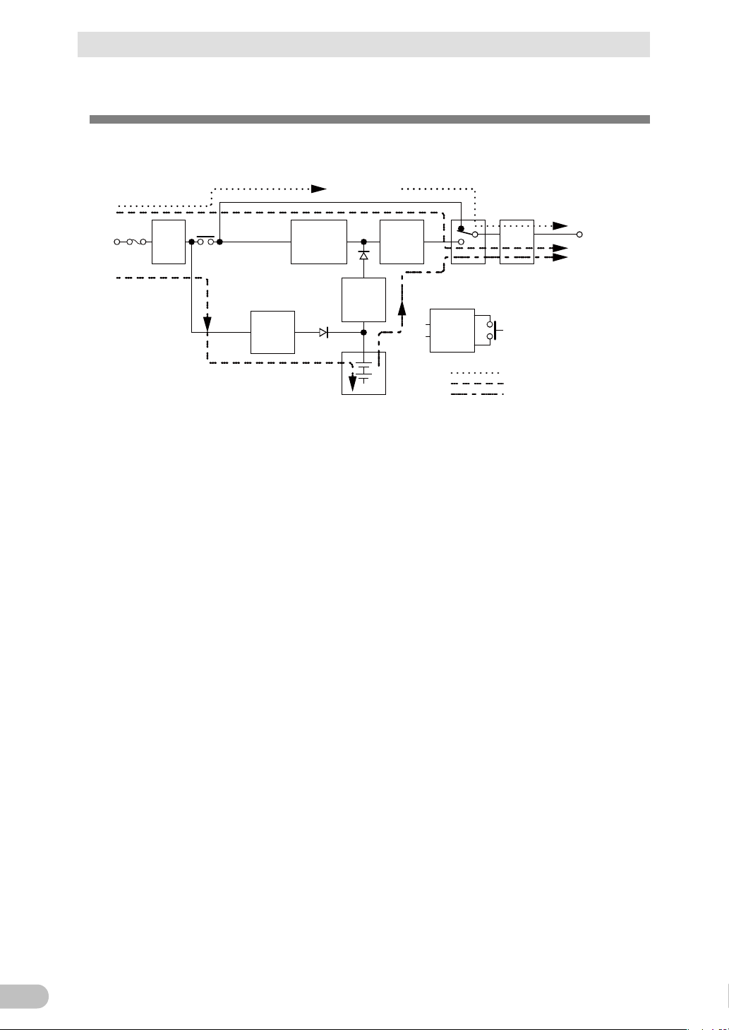
Noise
filter
Input
overcurrent
protection
AC100V
input
Power
supply
relay
Charging
circuit
Rectifier
(high power
factor
converter)
Step-up
converter
Inverter
(sine
wave)
Filter
Commercial
power bypass
output
Output
switching
(4 ms. max.)
Control
circuit
Power supply
switch
Battery
At startup/capacity exceeded/error
DuringLine mode
DuringBattery mode
Power
supply
output:
AC 100V
1-5 Diagram of the Input/output circuit block
1-5 Diagram of the Input/output circuit block
BU150R
Page 21
2 Installation and connection
21
Notes
Before installing this device, make a record of the serial number of this device. The
devices.
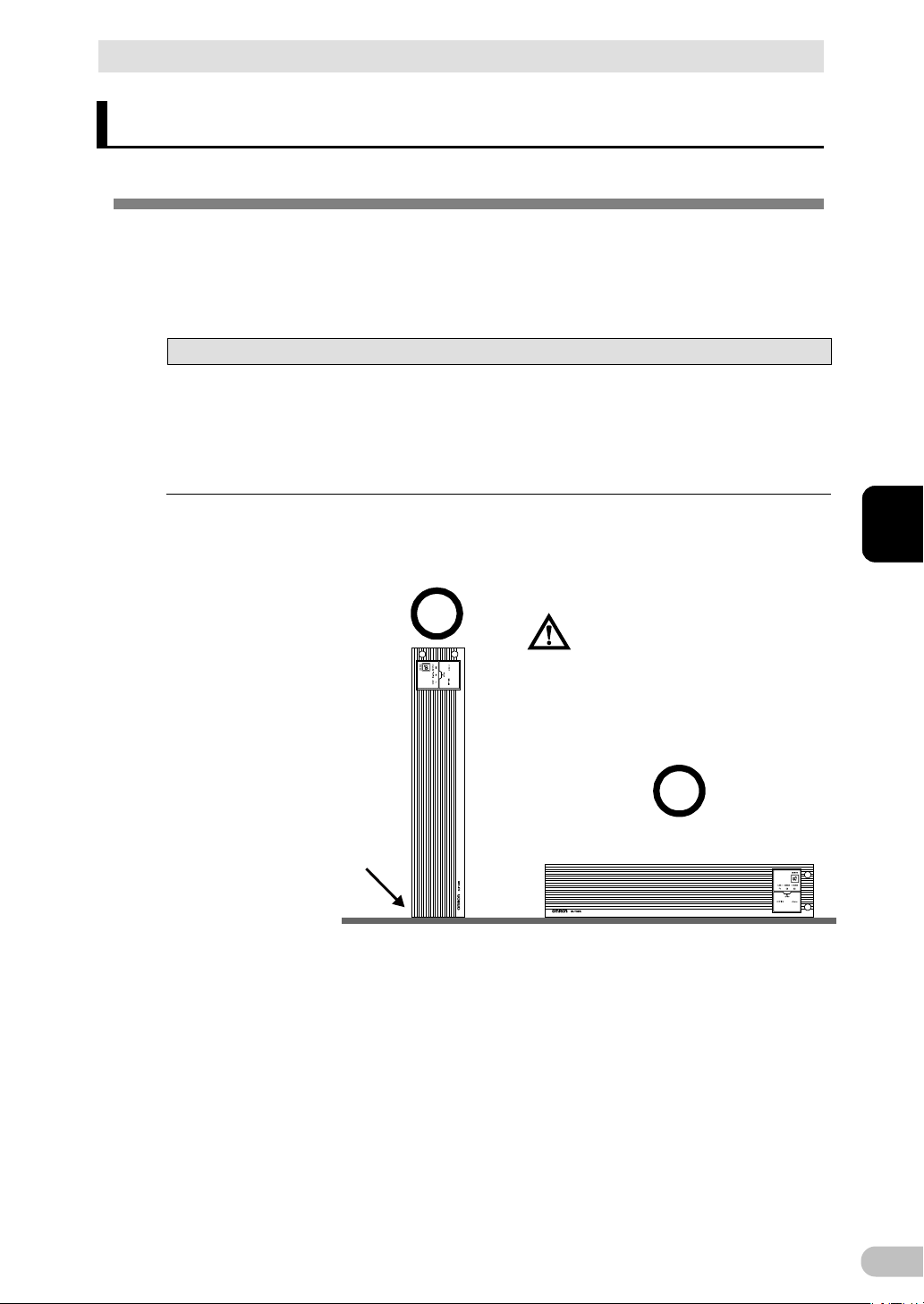
(Air vents are facing upward)
Ba careful not to get your fingers
caught when arranging the unit.
Correct Positions
Note: Upright stand is necessary
for this position.
2 Installation and connection
2-1 Installation
Install the UPS.
For cautions when installing the UPS, refer to "Caution (for installation and connection)"
shown in the "Safety precautions" of the beginning of this manual.
product serial number is required when contacting us about the device.
The serial number (S/N) is inscribed on the rear panel. The product serial number label is
also included.
Allow sufficient space at the back for the AC input cables of the UPS unit and connected
The UPS permits the following installing methods. Choose the one best suited for the
environment.
2-1 Installation
2
BU150R
Page 22
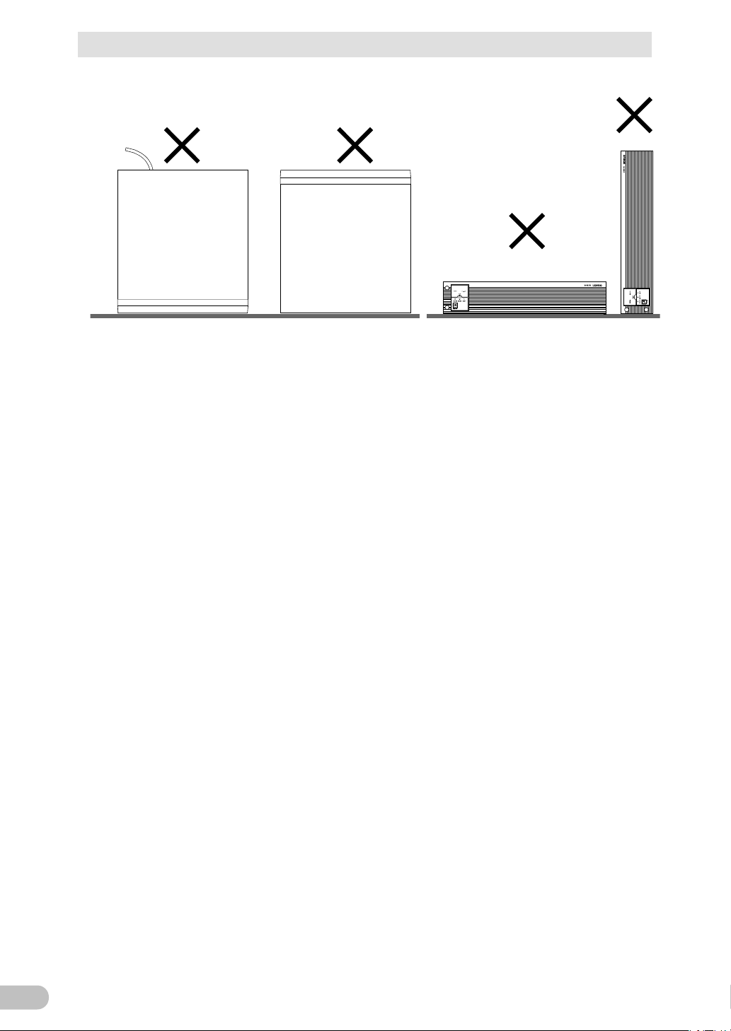
2 Installation and connection
22
Incorrect Positions
2-1 Installation
BU150R
Page 23
23
2-1-1 Rackmount installation
Caution (for installation and connection)
When performing rack installation, ensure that the UPS is
The mass of each unit : Approx. 21kg
In a case where the UPS is to be mounted on a rack, place it on
Dropping it may result in injury.
the UPS, causing it to fall.
Rack rail (front) L
1
Rack rail (front) R
1
Rack rail (rear)
2
Ear brackets
2
Rail length fixing screws (M4 x 8)
4
Ear bracket mounting flat-head screws (M3 x 6)
8
EIA/JIS rack fixing screws (M5 x 16)
10
JIS rack fixing flat-head screws (M5 x 14)
2
EIA rack fixing nuts (M5)
10
(EIA/JIS 19-inch rack/server rack)
supported and stabilized by using both the support angles and
the table clamps that were rated.
When installing on a rack, make sure that the UPS is supported by the
each unit individually.
When installing on a rack, make sure to use the support angles and table
clamps included with the product. Without the support angles, the front
clamp alone cannot support the weight of the UPS.
the lower part of the rack.
Be sure to use the supplied mounting screws.
Use of long screws other than those supplied for case mounting may
damage inside the unit.
When installing on a rack, make sure to use the support angles and table
clamps included with the product. Without the support angles, the front
clamp alone cannot support the weight of the UPS.
Screws other than those supplied may not be strong enough to support
2 Installation and connection
2-1 Installation
2
■Items included in the 19-inch rack support angle set
BU150R
Page 24
2 Installation and connection
24
1.
and right (R). The rear rack rails are same.
2.
Adjust the length of support angles to suit the server rack, and then securely tighten
4 rail length fixing screws
①
①
Rackrail (front)
Rack rail (rear)
2-1 Installation
●Rack mounting procedure
Insert the 4 included rail length fixing screws (M4) and half-tighten them to hold the
front and rear rack rails in place. (①
) There are 2 types of the front rack rail; left (L)
the screws that were half-tightened in step 1. (②)
BU150R
Page 25
2 Installation and connection
25
3.
screw hole from the bottom.
②
②
Adjust the length to
suit the server rack and
tighten securely
③
③
Rack fixing screws
Support angle
Server rack
2-1 Installation
For EIA standard-compliant installation, use the 8 included EIA rack fixing nuts (M5)
and 8 EIA/JIS rack fixing screws (M5) to securely fasten the front (the side
displaying "L" or "R") and the back of the support angles to the server rack. (③)
The screw holes are located at the top and bottom for both front and rear.
For JIS standards, use a total of 6 included screws to fix the rack; 1 JIS rack fixing
flat-head screw (M5) at a front position of the each of right and left support angles,
2 EIA/JIS rack fixing screws (M5) at 2 rear positions. (③
for the front is at the second screw hole from the top, the rear is at the second
) The screw hole position
2
BU150R
Page 26
2 Installation and connection
26
4.
5.
* Be sure to use the support angles.
④
④
Ear brackets
⑤
⑥
Push completely in
Use the unit fixing
screws to fasten
2-1 Installation
Use the 8 included ear bracket mounting flat-head screws (2 sets of 4 screws) to
securely fasten the ear brackets to the left and right sides of the UPS. (④)
Place the UPS on the support angles and push it completely into the rack (⑤), and
use the 2 included EIA/JIS rack fixing screws (M5) to securely fasten the ear
brackets to the server rack. (⑥)
BU150R
Page 27

27
2-1-2 Stationary installation
Stand f or vertical layput
Install the product horizontally or vertically.
■Horizontal installation
Attach the included rubber feet for horizontal installation and position the unit horizontally.
Make sure that this product does not slide or fall.
2 Installation and connection
2-1 Installation
2
■Upright installation
Attach the rack stands for vertical layout provided with the product to the UPS unit on the
left and right sides with M4 binding head 4 screws.
BU150R
Page 28
2 Installation and connection
28
Caution (for connection)
Overcurrent may damage the connected devices.
Power supply output group
Output Receptacle
Group A
NEMA5-15R 2 (rated capacity15A)
Group B
NEMA5-15R 2 (rated capacity15A)
Group C
NEMA5-15R 2 (rated capacity15A)
1.
and modems from a wall outlet (commercial power source).
Wall outlet
(commercial power source)
Computer peripheral devices
PC
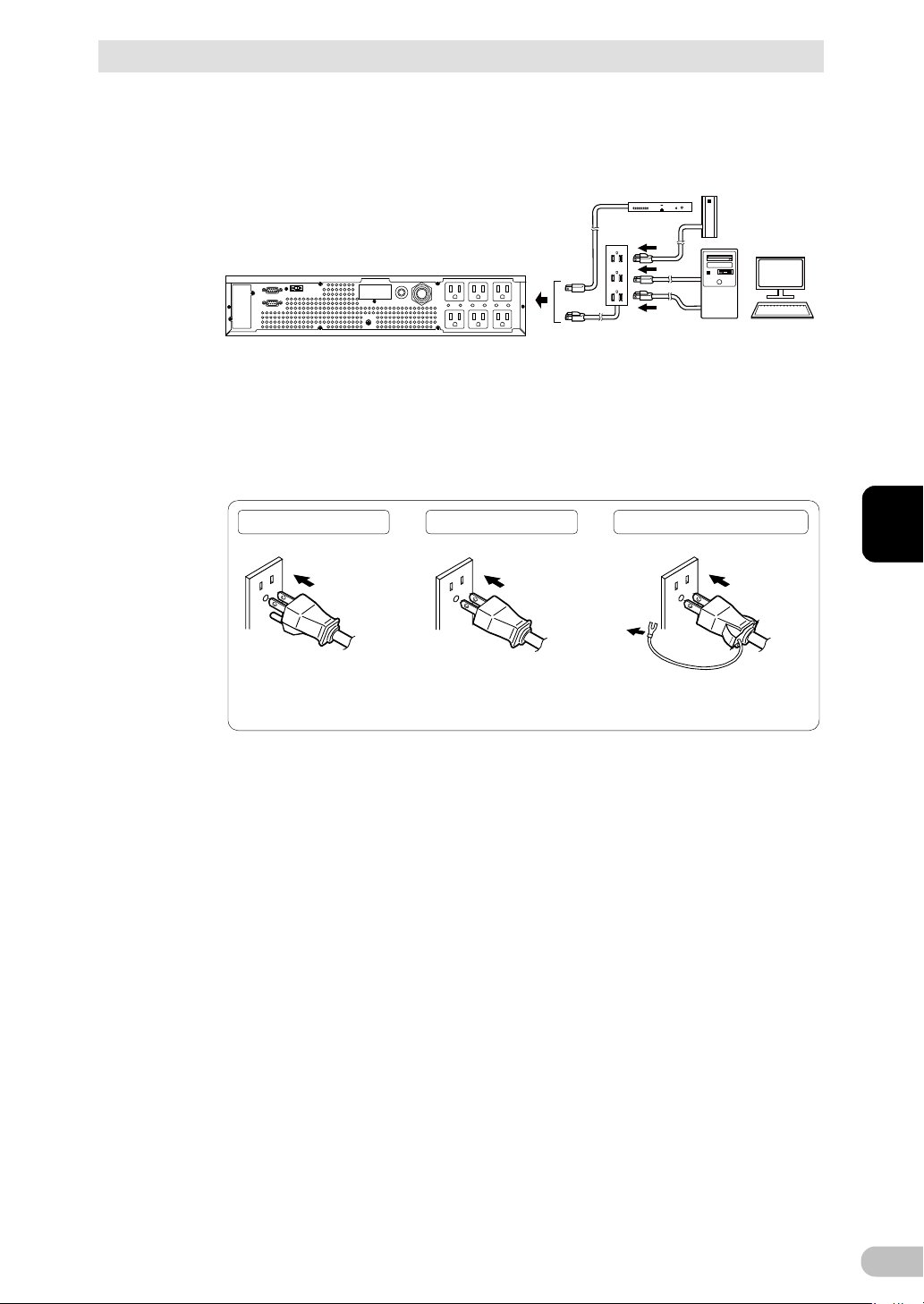
2-2 How to connect devices to back up
2-2 How to connect devices to back up
For cautions when connecting the UPS, refer to "Caution (for installation and connection)"
shown in the "Safety precautions" of the beginning of this manual.
Do not connect devices, rated voltage is not 100-120VAC.
The rated output voltage of this device is 100-120VAC.
Make sure that the total power consumption of the devices connected to the "power supply
output" receptacles does not exceed the output capacity rating. Reduce connected devices
if overload (OL) is displayed.
Disconnect the AC Input Plugs of all devices you want to back up such as your PC
BU150R
Page 29
2 Installation and connection
29
2.
3.
is not required.
External HDD
Computer peripheral devices
Connect it directl y. Connect it directl y. Connect the plug directl y.
Plug of connected
device
Plug of connected
device
Plug of connected
device
Connect the grounding wire of
connect devices to Input surge
protect ion GND of the UPS.
Connect the grounding wire to
Input surge protection GND of the
UPS.
2-2 How to connect devices to back up
Connect the AC Input Plugs to the Power Supply Output Receptacles of the UPS.
* If you need more output receptacles than those of the UPS, use a plug strip.
・When the connected device has a 2-pin AC input plug, it can be connected
directly to the power supply output receptacle. When using a 2-pin input plug with
a grounding wire, connect the grounding wire to earth .
・When you want to use an AC adaptor, connect it to a Power Supply Output
Receptacle of the UPS with space enough for the connection.
2
* For use as a UL standards or CE marking compliant product, this connection is
not possible.
When using the UPS monitoring software, use the included RS232C cable. When
using the Windows standard UPS service or the contact signal, use the rated
connection cable (BUC26) to connect the PC.
See also "5 To perform shutdown processing of the devices" ( P.77 ) and "6 The
contact signal functions" ( P. 84 ).
Note: If you do not use the UPS monitoring software and Contact Signal, this step
BU150R
Page 30
2 Installation and connection
30
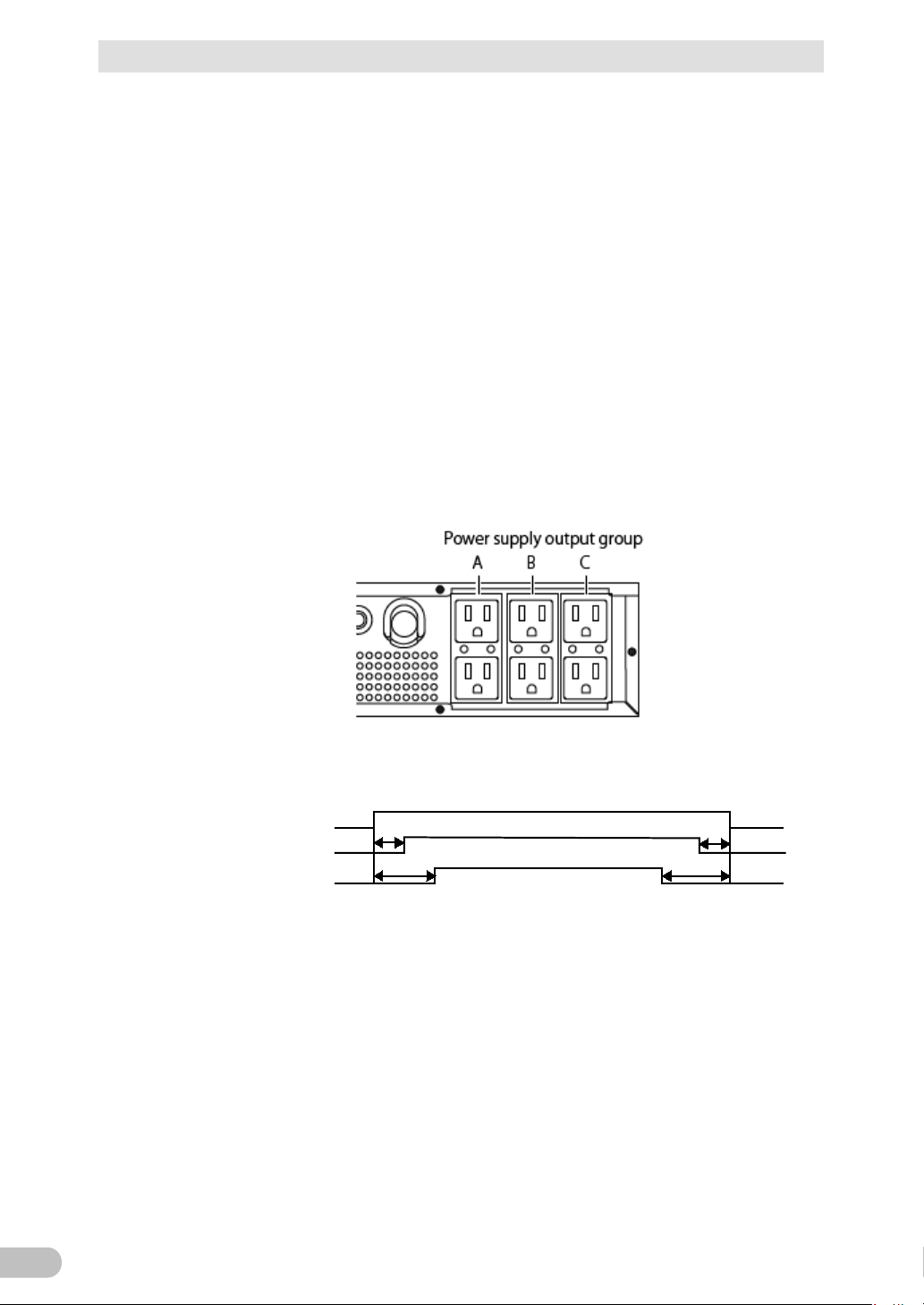
Power supply output
group A
Power supply output
group C
Power supply output
group B
Output ON
Output OFF
Time settingTime setting
Time setting
Time setting
2-2 How to connect devices to back up
■Group-based control of "power supply output"
When the attached automatic shutdown software is used, you can use the power supply
output group-based control function.
The power supply output receptacles of the UPS are divided into three groups, Groups A, B,
and C.
• Each of "power supply output" Groups B and C can delay its output start time or hasten
its output stop time independently of "power supply output" Group A.
• The output start and stop time control function can be controlled by the automatic
shutdown software "PowerAct Pro" or "SNMP/Web card".
• While the UPS is running, ON/OFF control can be performed on power supply output
from the automatic shutdown software.
• The above delay setting and ON/OFF control can be performed on each of "power
supply output" Groups B and C independently.
The order in which such equipment as servers and peripherals starts up can be set by
using this function.
In addition, forcible ON/OFF control on an output receptacle can be remotely performed.
■Fixing power cables
A connected power cable can be fixed with a retaining clip (BUX150R) provided as an
option.
This clip prevents an input plug from being detached in such a case as when the cable is
pulled.
BU150R
Page 31

31
2-3 Connecting the AC input
Caution (for installation and connection)
(commercial power source) with rated input voltage of
Reference
"3-2 Checking the operation" ( P. 40 ) can be performed also before charging the battery.
PC
3P
Receptacle
When installation and connection are complete, connect the unit's AC input plug to a wall
outlet (commercial power source).
Make sure to connect the AC input of the unit into a wall outlet
100/110/115/120V AC.
Connecting to a wall outlet (commercial power source) of a different rated
voltage may result in fire.
The unit may fail.
For other cautions when connecting the UPS, refer to "Caution (for installation and
connection)" shown in the "Safety precautions" of the beginning of this manual.
Connect the "AC input" plug to a 100 to 120VAC outlet (commercial power source).
2 Installation and connection
2-3 Connecting the AC input
2
The UPS is shipped with its battery charged. However, when the UPS is used for the first
time, its backup time may become short because the battery is left unused for a long
time.
We recommend charging the battery before using the UPS.
BU150R
Page 32

2 Installation and connection
32
N: White wire
L: Black wire
FG: Green wire
2-3 Connecting the AC input
■How to use a 20A AC input plug (NEMA L5-20P)
A 15A input plug (NEMA5-15P) is attached to the UPS by factory default. If the capacity is
not sufficient, use a 20A input plug (NEMA L5-20P).
Use the "Setting" switch "8" (see "3-1-4 Setting Switch" ( P. 35 ) ) to switch between 15A
and 20A.
Remove the 15A plug and connects the attached 20A plug (NEMA L5-20P) as shown in the
figure below.
Confirm the colors of the wires and fix with screws as shown in the figure.
Tighten with the tightening torque 1.57 Nm.
* Tightening with a torque other than the specified torque may lead to fire or burns.
BU150R
Page 33

3 Check and start operation
33
Sign
figure
LED
Color
Name
Status
Lit.
Not lit.
B Green
"Power
LED
The power supply
The power
the end of battery life.
A
B
E
G
D
C
F
A: Status indicator
B: “Power supply output” LED
C: “Battery mode” LED
D: “Battery replacement” LED
E: “Setting switch”
F: “Power” switch
G: “Buzzer Pause/Test” switch
<Enlarged view of the operation panel>
3-1 The name and function for the operation and display
3 Check and start operation
3-1 The name and function for the operation and
display
3-1-1 Name of each part
3-1-2 The meaning of each LED
of the
C
D
supply
output"
Orange "Battery
mode" LED
Red "Battery
replaceme
nt" LED
output is ON.
Backup is operating.
This status is called
"Battery Mode".
Battery replacement is
necessary due to the
battery deterioration or
3
supply output
is O F F.
Backup is not
operating.
Battery
replacement is
not necessary.
BU150R
Page 34

3 Check and start operation
34
figure
regardless of the "Power" switch.
3-1 The name and function for the operation and display
3-1-3 Switch
Sign
of the
F
G
Label Name 説明
Power switch ON: Press the "Power" switch of the UPS. The
power output from the UPS begins.
OFF: Press the "Power" switch of the UPS in ON
state, then the power output from the UPS stops.
Buzzer Pause/
Test switch
Additional Information:
If the AC input is connected to the commercial
power source, then the battery will be charged
Stop the beeper by pressing for 0.5 seconds or
longer
BU150R
Page 35

35
3-1-4 Setting Switch
After changing the "Setting" switch, turn off the AC input and pull off the AC input plug ,
Bit
Function to set
OFF side
ON side
failure, etc.
sound
power failure
performed
once every 4 weeks
performed
performed
by BS signal
only
6
Logic of Remote
on/off signal
Normally
opened
Normally
closed
8
Select AC input plug
15Aplug
20APlug
1 2 3 4 5 6
7 8
ON
After changing the "Setting" switch, follow the procedure described below.
wait until the status indicator is completely OFF, and then turn on the AC input.
Use a fine-pointed tool such as a small screwdriver to maneuver the switch's lever.
●Setting switch function list
3 Check and start operation
3-1 The name and function for the operation and display
1 Beeper sound in the
event of power
Beeper
sounds
Beeper
does not
2 Auto startup after
recovery from
3 ON/OFF the test
4 Auto startup mode
5 BS signal range Always
7
- - -
Auto startup
is performed
Te s t i s
Mode A Mode B
enabled
Auto startup
is not
Test is not
Enabled for
backup
operation
●Setting for beeper sound in the event of power failure, etc. ("Setting" switch 1) Factory setting: OFF
3
OFF:The beeper sounds when an alarm is necessary.
ON:The beeper does not sound for backup operation or battery replacement. The beeper
sounds for other errors (connection capacity exceeded, operation error, etc.).
BU150R
Page 36

3 Check and start operation
36
3-1 The name and function for the operation and display
●Auto startup setting after recovery from power failure ("Setting" switch 2) Factory setting: OFF
OFF : Automatically starts when power is restored.
After a power failure occurs and the unit shuts down using the shutdown software or
contact signal(BS signal), the unit automatically starts and begins to output when the
commercial power is restored.
ON: Does not automatically start when power is restored.
After the unit is shut down with the UPS monitoring software or contact signal (BS
signal), it does not start up when commercial power is restored. Startup is performed
by turning the "Power" switch OFF once, and then back ON again.
●Setting for whether or not to perform test once every 4 weeks ("Setting" switch 3) Factory setting: OFF
OFF: The self-diagnostic test is automatically executed once every 4 weeks.
ON:Does not perform the auto test once every 4 weeks.
Use this setting to disable Battery Mode for the regularly performed test.
●Auto startup mode setting ("Setting" switch 4) Factory setting: OFF
OFF: Mode A
After UPS stopped, the UPS is automatically started immediately when "ON" is
detected for the AC input.
ON: Mode B
After UPS stopped, the UPS is automatically started in the AC input's "OFF to ON"
timing that is detected.
(Definition of AC input OFF: When AC input is OFF for 1 second or more)
BU150R
Page 37

3 Check and start operation
37
AC input
Power output
(Setting switch 4 OFF:
Mode A)
Power output
(Setting switch 4 ON:
Mode B)
ON
OFF
ON
OFF
ON
OFF
ON
OFF
BS signal
*1
1 sec
AC input
Power output
(Setting switch 4 OFF:
Mode A)
Power output
(Setting switch 4 ON:
Mode B)
BS signal
*1
Starts up when BS signal
turns OFF
Starts up whenAC input
turns from OFF to ON
ON
OFF
ON
OFF
ON
OFF
ON
OFF
3-1 The name and function for the operation and display
* "Setting" switch 4 is valid when the auto startup after recovery from power failure setting
("Setting" switch 2) is set to OFF (auto restart is performed).
* This setting mode is valid only after the UPS has been stopped by the contact signal
backup stop signal (BS).
* When a cable is connected to the RS232C port and the UPS monitoring software is
used, the unit operates in Mode A regardless of this setting.
1) When BS signal is used to stop the UPS after a power failure occurs.
2) When BS signal is used to shut down the UPS when AC input is ON
3
BU150R
*1 For 10 seconds as a default setting.
Page 38

3 Check and start operation
38
3-1 The name and function for the operation and display
●BSsignal range setting ("Setting" switch 5) Factory setting: OFF
OFF: BS signal always effective (can be received)
The "power supply output" of the UPS can be stopped by turning the backup power
supply stop signal (BS) "ON" for ten seconds or longer.
ON: BS signal effective (can be received) for backup operation only (cannot be received
during commercial operation)
The "power supply output" of the UPS can be stopped by turning the backup power
supply stop signal (BS) "ON" for 0.01 seconds (10 milliseconds) or longer.
When you do not want to stop the UPS even if the backup power supply stop signal
(BS) comes in during commercial operation, make this setting.
●Logic of Remote on/off signal ("Setting" switch 6) Factory setting: OFF
OFF: UPS start shutdown process when detecting close condition of remote input signal.
ON: UPS start shutdown process when detecting open condition of remote input signal.
●AC input plug selection ("Setting" switch 8) Factory setting: OFF
OFF: Use 15Aplug
ON:Use 20A plug
BU150R
Page 39

39
3-1-5 Beep sound
ON
OFF
0.5second
2 second
ON
OFF
1 second
ON
OFF
4second
ON
OFF
Continuous
ON
OFF
■Type of beep sound
・Intermittent
0.5-second
intervals:
1-second
intervals:
・Continuous
■Stopping the beep sound
3 Check and start operation
3-1 The name and function for the operation and display
2-second
intervals:
4-second
intervals:
3
When the beep is sounding, you can stop it by pressing and holding the "STOP/TEST"
switch for 0.5 seconds or longer.
BU150R
Page 40

3 Check and start operation
40
1.
2.
commercial power and the status indication below is displayed.
indicator
Operating normally
When the battery capacity is lower than the setting, the following display appears
indicator
Battery charge is low, so the unit is waiting to start up.
3-2 Checking the operation
3-2 Checking the operation
When you finish connecting the unit, check that the Battery Mode is performed normally
according to the following procedure.
Pull out the "AC input" plug during operation and create the same situation as the
occurrence of a power failure to check the operation.
Press the unit's "Power" switch to turn ON the power.
When the power turns on, the beeper sounds and self diagnosis starts
automatically.
* If the battery voltage is low, the self-diagnostic test is not performed.
When the self-diagnosis test finishes normally, the unit's operation switches to
Status
Description
"Power" switch "ON"
on 7 segment LED.
( indicates blinking)
Status
Description
BU150R
Page 41

3 Check and start operation
41
3.
4.
Status
indicator
Beep
Power supply output receptacles
shown above
procedure 5.
5.
3-2 Checking the operation
Bring all the connected devices into operation. (Including devices connected to the
AC outlet of your PC.)
* Operate the connected devices in a way that allows the power supply to be
stopped at any time.
(Note)
The UPS has been charged prior to shipment. However, if it is left for a long period
of time, it may have self-discharged.
We recommend charging the UPS before using it. When you connect it to a
commercial power source, battery charging automatically starts regardless of the
ON/OFF state of the "Power" Switch and charging completes within 8 hours.
Under this condition, check the unit's LED display and beep sound.
None Outputs power (connected devices are powered)
If the same as the one
→ The operation is normal. Proceed to
If not the same as the one
shown above
Disconnect the unit's AC input from the commercial power.
The unit enters Battery Mode.
→ "3-4 Interpreting beeps and displays" ( P. 46 )
must apply.
Take necessary measures and then proceed
to 5.
3
BU150R
Page 42

3 Check and start operation
42
6.
Indicator
intervals
Mode continues.
intervals
output will stop soon.
7.
indicator
Operating normally
3-2 Checking the operation
In Battery Mode, check the unit's LED display and beep sound.
Check the status indicator appear as one of those shown below.
Status
Beep Output Description
( indicates blinking)
Intermittent
4-second
Intermittent
1-second
None OFF Battery is dead, so output stopped.
If not the same as one of those shown abov, operation is abnormal. Check the
status of lamps and beep, and then press the "Power" switch to turn OFF the
power.
・If the display is one of those shown in"3-4 Interpreting beeps and displays"
( P. 46 ) , take the necessary measures and then go back to procedure 1.
・If no Battery Mode is performed and the UPS and the devices connected to the
UPS stop, this may be attributed to an insufficient battery charge.
After connecting the AC input to the commercial power and charging the battery
for at least 8 hours, go back to step 5.
・If the problem persists after checking the 2 points above, contact us.
* "Setting" switch 1 can be used to turn the beeper ON/OFF.
Reconnect the AC input to the commercial power source.
Status indicator returns to its normal state and the beeping sound stops.
(The status is as shown below.)
Status
Description
ON Backup is operating due to power failure or
AC input error. Output will stop if Battery
ON Backup is operating due to power failure or
AC input error. Battery level is low, so
"Power" switch "ON"
Checking the operation is now complete.
BU150R
Page 43

3 Check and start operation
43
Status indicator
Beep
Power supply output receptacles
Outputs power (connected devices are
powered)
AC input
7 seg.
Power supply SW
Power supply
output lamp
Operating mode
Output
ON
OFF
ON
OFF
ON
OFF
Commercial
Power Battery
Commercial
Power Battery
<Note>
D-1: Display the latest UPS fault mode
(If there is no record for UPS fault, UPS display the
Startup
preparation
a few
seconds
Bypass
operation
a few
seconds
Self-diagnostic
test
about
15 sec.
Inverter
operation
D-1
1 sec.
3-3 Start and stop procedures and basic operation
3-3 Start and stop procedures and basic operation
3-3-1 Start and stop procedures
For cautions when operating the UPS, including start and stop, refer to "Caution (for use)"
shown in the "Safety precautions" of the beginning of this manual.
■Start procedure
Turn on the "Power" switch of the UPS.
・Output begins in Bypass Operation a few seconds after the switch is activated. (Status
indicator " ")
・The status indicator displays " ", and the self-diagnostic test is performed in Battery
Mode for about 15 seconds. If the battery voltage is low, the self-diagnostic test is not
performed. It is automatically executed after the battery is charged (approximately 8
hours). When the self-diagnostic test finishes successfully, switching to AC output from
commercial power is performed and normal operation starts.
・When the self-diagnosis test finishes normally, the unit enters the normal operating state
through inverter operation.
・When the self-diagnostic test is not performed, AC output begins immediately inverter
operation.
3
・During operation, the battery is charged automatically.
BU150R
None
Page 44

3 Check and start operation
44
Icon
Beep
Output
Description
and stop the UPS.
and stop the UPS.
3-3 Start and stop procedures and basic operation
■Operation when using
You may either leave the "Power" switch of the unit ON (operation status) or turn it OFF
each time when stopping the connected system. Choose whichever operation method is
more convenient.
We recommend turning OFF the "Power" switch when you do not use connected devices
for a long time.
The battery can be charged once the AC input terminal is connected to a commercial
power source.
■Operation after a power failure
・If a power failure or abnormal input power supply occurs, the UPS automatically switches
to Battery Mode, continuing power output from the Power Supply Output Receptacles
and output terminal block supplied from the battery.
・The status is displayed and the beeper sounds intermittently to alert the user.
* See also "Setting" switch 1 can be used to turn the beeper ON/OFF.
( indicates blinking)
Intermittent
4-second
intervals
Intermittent
1-second
intervals
None OFF Battery is dead, so output stopped.
ON Backup is operating due to power failure or AC
input error. Output will stop if Battery Mode
continues.
Process the shutdown of the connected devices
ON Backup is operating due to power failure or AC
input error. Battery level is low, so output will stop
soon.
Process the shutdown of the connected devices
Charge the batery.
■Operation when a power failure is recovered
When charge of the battery remains
The unit automatically resumes output via commercial power if it recovers from a power
failure/input power supply error while Backup is operating. The spent battery starts
charging.
When charge of the battery does not remain
If a power failure or abnormal power input is resolved after the battery is discharged
completely and power output is stopped, the UPS restarts automatically and resumes
power output. The expended battery begins to charge.
BU150R
Page 45

3 Check and start operation
45
devices (See also "3-1-4 Setting Switch" ( P. 35 ) ).
Note
Before stopping the commercial power to the unit, turn OFF the "Power"
When the AC Input Plugs are disconnected from a wall outlet (commercial power
frequently use the unit in Battery Mode, the battery life may be significantly shortened.
battery is automatically charged.
3-3 Start and stop procedures and basic operation
Additional Information
When the power is restored after a power failure, the UPS is set by default to automatically
restart and supply power.
If you do not want to restart the connected devices, "Setting" switch 2 can be used to select
whether or not auto restart is performed, or turn OFF the "Power" switch of the connected
■Operation when stopping
switch of the unit.
source), the unit enters Battery Mode. Before disconnection, turn off the “Power”.If you
Press and release the "Power" switch of the UPS, and then the "Power" switch turns OFF.
The power output from the UPS stops at the same time.
Additional Information
Even if you turn off the "Power" switch, if AC is supplied from commercial power, the
3
BU150R
Page 46

3 Check and start operation
46
lamp
Operation stopped.
OFF.
O
Disconnect.
lamp
normally.
battery. You can
Software.
Power
lamp
ging
indicates blinking
indicates the display is ON
indicates the display is OFF
3-4 Interpreting beeps and displays
3-4 Interpreting beeps and displays
3-4-1 Displays and beeps in normal operations
(1) When "Power" switch is "OFF"
No. Status
indicator
Power
supply
output
Battery
mode
lamp
Battery
replacement
lamp
Beep
Chargin
g
Description Solution
1
2
3
(1) When "Power" switch is "OFF"
No. Status
indicator
4
5
Power
supply
output
Battery
mode
lamp
Battery
replacement
lamp
None OFF
None ON
None ――
Beep
None ON
None ON
Chargin
No AC input.
There is AC input.
"Power" switch is
There is AC input.
"Power" switch is
OFF, or OFF ⇒
Battery
g
"Power" switch is
ON.
Operating
Battery charge is
low, so the unit is
waiting to start up.
――
――
Connect
Battery.
Description Solution
――
Continue
charging the
change the
settings with
Simple
Shutdown
3-4-2 Displays and beeps while testing
No. Status
6
Battery
mode
lamp
indicator
supply
output
NOT operation in bypass mode.
Battery
replacement
lamp
Beep
None
Chargi
ng
OFF
Dischar
Description Solution
Self-diagnostic test
in progress.
――
BU150R
Page 47

3 Check and start operation
47
Power
lamp
them.
interval s
output will soon stop.
few seconds.)
3-4 Interpreting beeps and displays
3-4-3 Displays and beeps during power failure or AC input
error
(1) When "Power" switch is "ON"
No. Status
indicator
7
supply
output
Battery
mode
lamp
Battery
replacement
lamp
Beep Charging Description Solution
Check that the
AC input cable is
Intermittent
4-second
interval s
OFF
Dischar ging
In Battery Mode due to
power failure or AC
input error. Output will
stop if Battery Mode
continues.
disconnect. If not
resume, perform
shutdown
operations for
the connected
devices and stop
Intermittent
8
9
1-second
None
OFF
Dischar ging
OFF
Dischar ging
(Same as above.)
Battery level is low, so
Battery is dead, so
output stopped. (This
is displayed only for a
(Same as
above.)
Charge the
battery.
3
NOT operation in bypass mode.
BU150R
Page 48

3 Check and start operation
48
Power
lamp
high.
too high.
too lo w.
too low.
3-4 Interpreting beeps and displays
(2) When "Power" switch is "OFF"
No
10
Status
indicator
supply
output
Battery
mode
lamp
Battery
replacement
lamp
Beep Charging Description Solution
AC input voltage
None (ON)
and AC input
frequency are too
11
12
13
14
15
16
17
None (ON)
None (ON)
None (ON)
None (ON)
None (ON)
None (ON)
None (ON)
AC input frequency
is too high.
AC input voltage is
too low and AC
input frequency is
AC input voltage is
too high.
AC input voltage is
too low.
AC input voltage is
too high and AC
input frequency is
AC input frequency
is too low.
AC input voltage
and AC input
frequency are both
Use within the
AC input
voltage/frequen
cy range
described in the
specifications.
BU150R
Page 49

3 Check and start operation
49
Power
lamp
Battery
interval s
Dischar ging
There are too many connected devices
begins promptly.
battery ambient temperature of 40°C or
switch back ON again.
Check that the connection capaci ty has
capacity.
Center.
3-4 Interpreting beeps and displays
3-4-4 Displays and beeps when there is an equipment
failure
(1) When "Power" switch is "ON"
No.
Status
indicator
supply
output
mode
lamp
Battery
replacement
lamp
Beep Charging Description Solution
18
19
20
21
22
blinking
bypass
or
Intermittent
0.5-second
Intermittent
0.5-second
interval s
OFF OFF
Continuous
Continuous
ON
or
ON
――
(Note 2)
―――
(Note 2)
and the rated capacity is exceeded. If
this state continues for as long as or
longer than the times described bel ow,
commercial power continues to be
supplied through bypass operation
(Note 1)
・ When connection capacity is at
110% or higher: Bypass operation
Battery charge stopped because the
higher was detected.
Output stopped due to exceeded
connection capacity.
not exceeded the rated capacity.
Reduce the number of
connected devices
until the display
appears as in status
No. 4
Lower the ambient
temperature to less
than 40°C.
Turn OFF the power
switches of all devices
connected to the unit
reduce the number of
connected devices,
and turn the “Power”
Check that the AC
input of connected
devices is not
short-circuited, or that
the connection
capacity does not
exceed the rated
3
23
BU150R
blinking
There is a problem
with the UPS or the
connected device.
bypass
Continuous
―――
(Note 2)
Switched to bypass operation due to
abnormal rise in output voltage. (Note
1).
Contact our sales
representative or
Omron Electronic
Systems & Equipment
Customer Support
Page 50

3 Check and start operation
50
There is a problem with
Center.
lamp
lamp
abnormal rise
completely.)
completely.)
while.
Center.
half wave rectification
wave
Replace the fan with a
fan" (P.73).
3-4 Interpreting beeps and displays
blinking
24
(1) When "Power" switch is "ON"
Status
No.
indicator
blinking
25
blinking
26
blinking
27
blinking
28
bypass
Power
supply
output
bypass
bypass
bypass
bypass
Battery
mode
lamp
Battery
replaceme
nt
the UPS or the
connected device.
Continuous
―――
(Note 2)
Switched to bypass operation due to
abnormal drop in output voltage. (Note
1).
Contact our sales
representative or
Omron Electronic
Systems & Equipment
Customer Support
Beep Charging Description Solution
Stopped charging due to
Continuous
Continuous
Continuous
Continuous
OFF
OFF
―――
(Note 2)
―――
(Note 2)
in battery charge voltage. When the
battery discharges, bypass output is
performed. (The display disappears
Stopped charging due to abnormal
drop in battery charge voltage. When
the battery discharges, bypass output
is performed. (The display disappears
Moved to bypass operation due to
problem with the internal temperature
(Note 1).
Moved to bypass operation due to
problem with the DC Bus
voltage .(Note 1).
The UPS may be
faulty. Ask for repair.
(Same as above.)
Stop the connected
device.
Power off the UPS,
and start after a
There is a problem
with the UPS or the
connected device.
Contact our sales
representative or
Omron Electronic
Systems & Equipment
Customer Support
29
30
blinking
blinking
bypass
bypass
Continuous
Continuous
―――
(Note 2)
―――
(Note 2)
Moved to bypass operation due to
problem with the
load (Note 1) (Note 3)
External Fan Error.
Remove the half-
rectifying load.
spare (optional).
For details on how to
replace the fan, see
"4-3 Replacing the
BU150R
Page 51

3 Check and start operation
51
3-4 Interpreting beeps and displays
Note 1 In bypass operation, commercial power is output directly. Output stops when a power
failure
(AC input OFF) occurs in bypass operation.
Note 2 The displays and operations vary according to the status.
Note 3 Devices such as dryers, some solenoid valves, etc., which have a half-wave rectifier.
3
BU150R
Page 52

3 Check and start operation
52
Power
lamp
Center.
Power
lamp
battery"( P. 65 )
continue.)
battery"( P. 65 )
3-4 Interpreting beeps and displays
(2)When "Power" switch is "OFF"
No.
35
36
Status
indicator
supply
output
Battery
mode
lamp
Battery
replacement
lamp
Beep Charging
Continuous OFF
Continuous OFF
Continuous OFF External Fan Error.
Stopped charging due to abnormal
rise in battery charge voltage.
Stopped charging due to abnormal
drop in battery charge voltage.
Description Solution
3-4-5 Display and beep for battery replacement
No
Status
indicator
supply
output
Battery
mode
lamp
Battery
replacement
lamp
Beep Charging Description Solution
There is a problem
with the UPS.
Contact our sales
representative or
Omron Electronic
Systems &
Equipment
Customer Support
(Same as
above.)
(Same as
above.)
37
38
39
―― ―― ――
Intermittent
2-second
intervals
Intermittent
2-second
intervals
None
ON
ON
――
The
self-diagnosis
test detected a
weak battery
(warning only,
output
continues).
Battery life
counter went
off-scale.
(Warning only.
Outputs
Battery life
counter has
been reset.
Replace the battery.
You can replace the
weak battery with a
separately
purchased
replacement battery
as needed.See also
"4-2
Replacing the
(Same as above.)
Be sure to reset the
battery life counter
after replacing the
battery.
See also
"4-2
Replacing the
BU150R
Page 53

3 Check and start operation
53
This timing is 10 sec.
Power output stop decay
ON
ON
ON
OFF
OFF
OFF
AC input
BS signal
Power supply
output
3-5 UPS operation mode settings
3-5 UPS operation mode settings
3-5-1 Settable items and explanations
There are eight to select.
1) Output voltage setting
2) Maximum backup time setting
3) Reboot battery voltage setting
4) BS signal delay setting
5) BU signal delay setting
6) Dry contact logic setting
7) Dry contact test
8) Expansion unit count setting
The settings available for this operation are shown below.
1. Output voltage setting (100V/110V/115V/120V)
Four types of output voltage can be set.
(Setting range: 100V/110V/115V/120V, Default setting: 100V)
Output is performed at the set voltage, with no relation to the input voltage.
2. Maximum backup time setting
Maximum backup time can be set.
(Setting range: 0 to 90 minutes, Default setting: 0 minute)
3. Reboot battery voltage setting
The limit battery capacity for wake-up can be set.
(Setting range: 0 to 90%, Default setting: 0%)
4. BS signal delay setting
It is possible to set the delay time for stopping the power supply output after the BS
signal is received. (Setting range: 0 to 10 minutes, Default setting: 0 minute)
3
BU150R
5. BU signal delay setting
It is possible to set the delay time of BU signal after AC fail occur.
(Setting range: 0 to 90 seconds, Default setting: 0 second)
6. Dry contact logic setting (BU,BL,TR,WB)
Four types of output signal can be set On/Off
(See also "6-1 Contact signal functions").
Page 54

3 Check and start operation
54
ON
OFF
ON
OFF
ON
OFF
ON
OFF
ON
OFF
ON
OFF
ON
OFF
Battery Low signal (BL)
Trouble signal (TR)
Backup signal (BU)
Deteriorated battery signal
(WB)
Backup power supply stop
signal (BS)
Remote ON/OFF signal
Beep
Output signal
Input signal
While the signal is being input, these status
indications blink and the beep sounds.
Signal input/output test st art
Signal output test
Contact signal is forced to tur n ON.
Signal input test
While the signal is being input,
the status indicator blinks and
the beep sounds.
Signal input/output test end
3-5 UPS operation mode settings
7. Dry contact test (BL/TR/BU/WB/BS/remote)
Four types of output signal can be forcibly turned ON.
The ON/OFF state of two types of input signal can be checked with the status indicator
and the beeper.
8. Expansion unit count setting
The number of expansion batteries "BUM150RA" to be connected is set.
Be sure to set this when using expansion batteries.
If the setting is not made correctly, it may cause a drop in backup time.
Setting range : 0 - 6 ( Default setting : 0 )
BU150R
Page 55

55
3-5-2 Settings
1.
By using the following procedure, set the operation mode.
The "Power" switch is turned ON while the "Buzzer Pause/Test" switch is pressed.
The UPS operation mode can be set.
3 Check and start operation
3-5 UPS operation mode settings
Note: While in setting mode, output from the power supply output is OFF even if
the "Power" switch is ON.
3
BU150R
Page 56

3 Check and start operation
56
2.
3.
4.
5.
Press the "Power" switch again to start up the UPS.
Output voltage
Maximum backup tim e
Reboot battery voltage
BS signal delay
BU signal delay
Dry contact logic
Dry contact test
Expansion unit count setting
3-5 UPS operation mode settings
When the "Buzzer Pause/Test" switch is briefly pressed (for less than 1 second),
the next item is displayed.
The setting items are displayed in the following order.
Hold down the "Buzzer Pause/Test" switch (for one second or longer) to enable the
selected item.
Shortly press the "Buzzer Pause/Test" switch (for one second or shorter) to select a
parameter.
When the "Power" switch is turned OFF, the setting mode quits and the unit enters
"Power" switch OFF status (status ).
BU150R
Page 57

57
(B)
(B)
(B)
(B)
(B)
(B)
(B)
(B)
(B)
(B)
(C)
(C)
(A) (E)
(C)
(C)
(B)
(B)
(B)
Output 110V
Output 115V
Output 120V
Backup 0.1 min.
Backup 0.2 min.
Backup 0.9 min.
(0.1 min. step)
No setting (infinity)
(Default)
Backup 1 min.
Backup 2 min.
Backup 10 min.
(1 min. step)
Backup 20 min.
Backup 90 min.
(10 min. step)
Maximum backup time
("BUT" setting)
Display
current
setting
Output 100V
(Default)
Output voltage setting
("Out" setting)
Display
current
setting
Normal operation mode
(next page)
3 Check and start operation
3-5 UPS operation mode settings
<Operation symbols in the figure>
Operation (A) : pressing the "Buzzer Pause switch" and turn on the "Power" switch.
Operation (B) : pressing the "Buzzer Pause switch" under 1 second and then release it.
Operation (C) : pressing the "Buzzer Pause switch" 1 to under 5 second and then release it.
Operation (D) : pressing the "Buzzer Pause switch" 5 second or more and then release it.
Operation (E) : turning off the "Power" switch.
3
BU150R
Page 58

3 Check and start operation
58
(B)
(B)
(B)
(B)
(B)
(B)
(B)
(B)
(B)
(C)
(C)
(C)
(C)
(B)
(B)
(B)
(B)
Charge 10%
Charge 20%
Charge 90%
Delay 0.2 min.
Delay 0.5 min.
Delay 1 min.
(10% step)
Delay 0 min.
(Default)
Delay 2 min.
Delay 10 min.
Disable
(1 min. step)
BS signal delay
("DBS" setting)
Display
current
setting
Charge 0%
(Default)
Reboot battery voltage
("RBV" setting)
Display
current
setting
(previous page)
(next page)
3-5 UPS operation mode settings
BU150R
Page 59

3 Check and start operation
59
(B)
(B)
(B)
(B)
(B)
(C)
(C)
(B)
(C)
(C)
(B)
(C)
(C)
(B)
(B)
(B)
(B)
(B)
(B)
(B)
(B)
(B)
(B)
(B)
(B)
(B)
(D)
Delay 1 sec.
Delay 2 sec.
Delay 9 sec.
Delay 0 sec.
(Default)
Delay 10 sec.
Delay 20 sec.
Delay 90 sec.
(10 sec. step)
BU signal delay
("DBU" setting)
Display
current
setting
Current state of
BL signal
Current state of
TR signal
Current state of
WB signal
Current state of
BU signal
Dry contact logic
("LDC" setting)
Display
TR signal test
BU signal test
WB signal test
BL signal test
Dry contact test
Display
Remote ON/OFF test
BS signal test
or
or
or
or
(previous page)
(1 sec. step)
Set and
display
reversed
setting
Off activeOn active
3-5 UPS operation mode settings
3
BU150R
Page 60

3 Check and start operation
60
(B)
(B)
(B)
(B)
(B)
(B)
(B)
(C)
(C)
(B)
(B)
Expansion battery unit
1 unit
Expansion battery unit
2 units
Expansion battery unit
3 units
Expansion battery unit
4 units
Expansion battery unit
5 units
Expansion battery unit
6 units
Expansion unit count
setting
Display
current
setting
(previous p age)
b1
Expansion battery unit
0
b0
b2
b3
b4
b5
b6
3-5 UPS operation mode settings
BU150R
Page 61

4 Maintenance and Inspection
61
Ambient
temperature
Battery life
expectancy
4 Maintenance and Inspection
For cautions when maintaining the UPS, refer to "Caution (for maintenance)" shown in the
"Safety precautions" of the beginning of this manual.
4-1 Checking the battery
The lead battery used in the unit has a limited lifespan.
The life varies depending on your storage/use environment and backup frequency.
*The nearer the end of the life is, the more rapidly deterioration proceeds.
4-1-1 Battery life expectancy
4-1 Checking the battery
25℃
30℃
35℃
40℃
* Not a guaranteed performance
5 years
3.5 years
2.5 years
1.7 years
4-1-2 Self-diagnosis test
This test performs a failure diagnosis on the unit and performs a test to check for battery
deterioration.
Use the procedure below to check whether a circuit failure has occurred inside the unit and
whether battery replacement is required.
There are two, automatic testing and manual testing, in the self-diagnosis test as follows.
■Automatic testing
The self-diagnosis test is automatically performed at the following timing in the state that
the UPS is connected to a commercial power source and the charge of the battery has
been completed.
User's operation to start the test is unnecessary.
・When the "Power" switch is turned ON from OFF
・Performed with one time per four weeks on the condition that the "Power" switch is ON
When charge of the battery is not completed, the self-diagnosis test is not performed
immediately.
* The automatic execution of a self-diagnostic test every four weeks can be turned
ON/OFF using the "Setting" switch 3.
4
BU150R
Page 62

4 Maintenance and Inspection
62
Additional Information
For more details, refer to the online help of UPS monitoring software.
1.
2.
3.
indicators are turned off.
4-1 Checking the battery
■Manual testing
This test can also be performed manually. Press and hold
the "Buzzer Pause/Test" switch of the UPS for 5 seconds
or longer. When the beeper begins to sound intermittently,
release the Switch.
By performing the self-diagnosis test, backup operation is
started automatically.
Status indicator " ", No beep sounds.
After the test is completed, UPS automatically returns to
the normal operation.
Follow the directions for the solutions described in "3-4 Interpreting beeps and
displaysInterpreting beeps and displays", "3-4-4 Displays and beeps when there is an
equipment failure" ( P. 49 ) and "4-2 Replacing the battery" ( P. 65 ) .
The self-diagnosis test can be performed also from attached UPS monitoring software.
4-1-3 How to measure backup time
Connect the "AC input" plug to an outlet (commercial power source) and charge the
battery for eight hours or longer (for 24 hours or longer per an expantion battery
unit when an expansion battery unit is connected).
Turn the power on for all the connected devices including the device connected to
the power supply output receptacle of your computer.
* Operate the UPS in a state in which the power supply can be stopped for the
connected devices in the middle of their operation.
* For WindowsServer2003/Vista/XP/Me/2000/WindowsNT/Linux/Mac, carry out this
procedure when the hard disk (HD) is stopped.
Pull out the AC input plug and measure the backup time.
Measure the period of time from when the UPS automatically stops until all the
The backup time measured for the first time after purchasing the UPS becomes the
"backup time initial value".
BU150R
Page 63

63
4-1-4 Estimated backup time
1.
Indication
Value
A
A × power factor × 100 = W
VA
VA × power factor × 100 = W
2.
3.
The backup time varies depending on the capacity of connected devices.
After calculating the total capacity of connected devices, refer to the graph of the backup
time to obtain an estimation of the initial value of the backup time. (This is also applied to
checking the battery.)
Convert the total capacity (power consumption) of the connected devices to watts
(W).
For the indication of connected devices, check your computer and the rear of the
display.
The indicator can show values in three different ways: volt-amperes (VA), amperes
(A), and watts (W).
(Example)
AC100V、50/60Hz、145W
AC100V、50/60Hz、1.8A
AC100V、50/60Hz、150VA
4 Maintenance and Inspection
4-1 Checking the battery
For devices that use the VA or A indication, convert the capacity into W. Multiply the
value indicated on devices by the value in the right table for conversion.
(When the power factor is unknown, enter "1". The power factor usually ranges
between 0.6 and 1.)
Add the values converted into W to obtain the total capacity of the connected
devices.
Calculate the initial value of the backup time for the total capacity of the connected
devices from the graph on the next page.
* The smaller the capacity of connected devices becomes, the longer the backup
time becomes.
* The smaller the capacity of connected devices becomes, the longer the backup
time becomes.
4
BU150R
Page 64

4 Maintenance and Inspection
64
Connected capacity (W)
50
100
200
300
400
500
600
700
800
900
1000
1200
none
241
126
65
41
29.5
22.5
18.5
14
13
10
8.4
6.5
1 connected
750
438
235
153
107
83
67
55
47
40
35
29
2 connected
1100
700
380
260
187
150
125
105
90
75
68
58
Connected capacity (W)
100
200
300
400
500
600
700
800
900
1000
1200
3 connected
1050
575
370
273
214
175
148
132
113
100
82
4 connected
1300
720
482
355
283
235
194
167
145
130
108
5 connected
1580
850
580
426
341
285
235
200
180
160
132
6 connected
1680
1030
710
517
414
345
285
245
212
190
158
4-1 Checking the battery
Graph of backup time (graph of initial values for products that have not been used at 25°C).
Backup time (min)
Backup time
(min)
Backup time (min)
Backup time
(min)
* These backup times are for reference only. Times may vary according to battery life and
external environmental conditions (temperature, etc.).
BU150R
Page 65

65
4-2 Replacing the battery
Caution (for battery replacement)
When replacing batteries replace with the same type and
number of batteries or battery packs.
Notes
When the unit is used in compliance with UL standards or CE marking, battery
Guidance for replace service " provided with the replacement battery pack.
Additional Information
Pause/Test" switch for 0.5 seconds to stop the beeper. (Lighting/blinking of "battery
replacement" LED does not disappear.)
The battery can be replaced while the unit is stopped (power supply output stopped).
Refer to the below-shown reference data "10-3 Battery life" for the details about the life of
the battery.
Risk of explosion if battery is replaced by an incorrect type.
Be sure to reset the battery life counter after replacing the battery.
Press and hold the "Buzzer Pause/Test" switch of the UPS for 10 seconds or longer to
reset the battery life counter. Resetting is complete when "bJ" is displayed.
* Reset the battery life counter with the "AC input" plug connected.
・Stopping ("Power" switch OFF): When the beeper becomes a sustained beep,
release the switch.
・In Commercial Power Mode ("Power" switch ON): When the beeper changes from
intermittent beeps to a sustained beep, release the switch.
If you do not reset the battery life counter, a battery deterioration alarm may occur
faster than the expected battery life.
replacement should be performed or supervised by personnel familiar with the danger of
batteries and the required precautions.
If an input power supply error such as a power failure occurs when replacing the battery
while in operation, backup cannot be performed and output stops.
Do not replace the battery while the UPS is operating in backup mode. Output will stop.
Write the battery replacement date in the attached battery replacement date sticker
provided with the replacement battery pack, and attach the sticker to the UPS.
* We are collecting replaced and unneeded batteries at no cost provided that the costs
of shipment to us are borne by the customers. For details, see the attachment "
4 Maintenance and Inspection
4-2 Replacing the battery
4
When the battery replacement LED lights up/blinks and beeper sounds, press the "Buzzer
BU150R
Page 66

4 Maintenance and Inspection
66
Notes
the shorter battery life.
Average ambient
temperature
6-month check
Monthly check
starting use
passed after starting use
For the first 3 years after
starting use
When 3 years or more have
passed after starting use
starting use
passed after starting use
4-2 Replacing the battery
4-2-1 Notification that the battery needs to be replaced
This Battery life counter function notifies you with LED display and beep sound when the
battery needs to be replaced.
The battery life is determined by the counter function. The battery life counter operates
while commercial power is supplied after shipment. (When the ambient temperature of the
battery is higher than 25°C, the value of the counter will be incremented at a faster pace.)
The lead battery used in the unit has a limited lifespan. The life varies depending on your
storage/use environment and backup frequency.
The nearer the end of the life is, the more rapidly deterioration proceeds.
Refer to the below-shown reference data " 10-3 Battery life " for the details about the life
of the battery.
Even if battery is storage condition, deterioration proceeds. The higher the temperature i,
■Guidelines for how often to check the battery
40℃
30℃
25℃
For the first 1 years after
For the first 4 years after
When 1 years or more have
When 4 years or more have
BU150R
Page 67

4 Maintenance and Inspection
67
1.
2.
①
Loosen the two screws
with a + screwdriver
②
Pull the right side of the front
panel towards you to detach
the front panel
Front panel
side
Clamp
③
①②Remove the locking
clip
Hold the battery
connector, and pull
the connectors apart
4-2-2 Procedure for replacing the battery
For cautions when replacing the battery of the UPS, refer to "Caution for battery
replacement)" shown in the "Safety precautions" of the beginning of this manual.
Loosen the two screws on the right side of the front panel with a + screwdriver
(①). Pull the right side of the front panel towards you to detach the front panel (②).
* Do not pull the front panel strongly towards you. The clamp may be damaged.
Pull the front panel towards you a little first, and detach the front panel while
sliding it to the right(③).
4-2 Replacing the battery
BU150R
Remove the battery connectors from the cable holders.
Remove the locking clip of connectors (①).
Hold the battery connector, and pull the connectors apart (②).
4
Page 68

4 Maintenance and Inspection
68
3.
4.
①
Sheet metal cover
Screw
①
②
4-2 Replacing the battery
Remove the screw on the sheet metal cover (①).
Lightly push in the sheet metal cover to the right (①) first, and pull the left side
towards you to detach it (②).
BU150R
Page 69

4 Maintenance and Inspection
69
5.
Red tape
Recess
4-2 Replacing the battery
Put your finger into the recess at the bottom of the battery pack and pull the
battery pack out. When the red tape attached to the top of the battery pack
appears, you can completely remove the battery by pulling it towards you 10cm
more. Hold the battery tight with both hands and be careful not to drop the battery.
* To pull out the battery pack, do not take hold of its connector or cable.
* Handle with care as the battery pack is heavy.
4
BU150R
Page 70

4 Maintenance and Inspection
70
6.
7.
③
②
Sheet metal cover
①
4-2 Replacing the battery
Insert a new battery into the UPS as far as it will go.
・Replacement battery pack : model : BUB150RA
Insert the right end of the sheet metal cover into the UPS unit (①), push the left
side in (②), and attach it by sliding it to the left (③).
BU150R
Page 71

4 Maintenance and Inspection
71
8.
9.
① ②Connect by holding
here
Inser t the connecto r’s
groove into the holder
Cable holder
4-2 Replacing the battery
Fix the sheet metal cover with a screw.
Connect the battery connector (①) and insert the connector's groove into the
holder (②).
Attach the battery cable to the cable holder.
Note : You may hear a “pop” sound when you connect the battery if it is replaced
after the unit’s operation is stopped, but this sound is not abnormal.
4
BU150R
Page 72

4 Maintenance and Inspection
72
10.
③
Tighten the two screws
②
Push the right side of
the front panel in
①
Insert the clamp on the left
side of the front panel into a
groove on the UPS unit
Clamp
Front panel
side
4-2 Replacing the battery
Attach the front panel to the unit.
Insert the clamp on the left side of the front panel into a groove on the UPS unit
(①), and push the right side of the front panel in (②).
Securely tighten the two screws on the right side of the front panel with a +
screwdriver (③)
Battery replacement is now complete.
BU150R
Page 73

73
4-3 Replacing the fan
Caution (for replacing the fan)
Fan replacement does not comply with UL standards or CE
marking.
Do not insert your hand or metal objects into the fan
Doing so may cause electric shock or short-circuit.
Do not put your fingers into the fan.
Doing so may result in injury.
Before turn off the “Power”, disconnect the AC Input Plugs
The fan in the unit has an expected lifespan of approximately 5 years.
Replace it when the Error Lamp is lit and the fan is stopped.
When this product is used in compliance with UL standards
or CE marking, do not replace the fan.
recess.
The fan spins when connecting the AC input.
from a wall outlet (commercial power source).
4 Maintenance and Inspection
4-3 Replacing the fan
4
BU150R
Page 74

4 Maintenance and Inspection
74
1.
Loosen the two screws on the right side of the front panel with a + screwdriver
2.
①
Loosen the two screws
with a + screwdriver
②
Pull the right side of the front
panel towards you to detach
the front panel
Front panel
side
Clamp
③
Fan guard
Fan
4Screws
①
②
4-3 Replacing the fan
4-3-1 Fan replacement procedure
* Make sure that UPS doesn't connect to any AC inputs and the fan stops.
(①). Pull the right side of the front panel towards you to detach the front panel (②).
* Do not pull the front panel strongly towards you. The clamp may be damaged.
Pull the front panel towards you a little first, and detach the front panel while
sliding it to the right(③).
Remove the 4 cooling fan screws (①) and the fan guard.
Pull the fan toward you to remove it. (②)
BU150R
Page 75

4 Maintenance and Inspection
75
3.
4.
Insert the new fan connector until it clicks into place.
5.
①
②
②
Fix the fan guard and the fan
together with four screws
①
Insert the fan into
the UPS unit
4-3 Replacing the fan
While pressing up on the tip of the fan connector (①), pull it toward you to
disconnect it. (②)
・Replacement fan : Model BUF150R
Insert the fan into the UPS unit. Place the fan guard (①) and fix the fan guard and
the fan together with four screws (②).
* Make sure the cable does not become pinned under the fan's cover.
* Fix so that the label on the fan unit faces the back side.
4
BU150R
Page 76

4 Maintenance and Inspection
76
6.
③
Tighten the two screws
②
Push the right side of
the front panel in
①
Insert the clamp on the left
side of the front panel into a
groove on the UPS unit
Clamp
Front panel
side
4-4 Cleaning
Attach the front panel to the unit.
Insert the clamp on the left side of the front panel into a groove on the UPS unit
(①), and push the right side of the front panel in (②).
Securely tighten the two screws on the right side of the front panel with a +
screwdriver (③)
Fan replacement is now complete.
4-4 Cleaning
Moisten a soft cloth with water or detergent, squeeze it tightly, and wipe the product lightly.
Do not use chemicals such as thinner and benzene. (They cause deformation or
discoloration.)
BU150R
Page 77

5 To perform shutdown processing of the devices
77
Notes
finished, do not turn on the computer until the UPS has finished restarting.
5-1 The outline on the UPS monitoring software
5 To perform shutdown processing of
the devices
5-1 The outline on the UPS monitoring software
Automatic shutdown software is a software application for controlling the connected
computer such as performing end processing when the UPS detects an input voltage error
(such as a power failure).
Restrictions on the commercial power interruption time during the scheduled operation
by automatic shutdown software
While the scheduled operation is set, if the UPS is not connected to a commercial
power source for a long period of time, the internal timer will be reset.
・To keep the internal timer active, connect the UPS to a commercial power source in
approximately three months.
※Battery deterioration over time reduces the period for keeping the internal timer
active.
When manually starting during the scheduled operation using the UPS monitoring software
To manually start up this unit after it has been stopped by a scheduled operation, turn
OFF the "Power" switch and turn it back ON again.
To stop the unit when it is in operation, turn OFF the "Power" switch.
Auto restart after OS closing processing using the UPS monitoring software.
When the power is restored while auto shutdown processing is being performed
If a power failure occurs and then the power is restored while auto shutdown is still in
progress, UPS output will stop temporarily after the set time elapses. After shutdown is
5
BU150R
Page 78

5 To perform shutdown processing of the devices
78
Functions
standalone)
functions, network support)
Simple Shutdown Software
PowerAct Pro
Refer to the section number
Section 5-2
Section 5-2
(operating status)
3.
UPS monitoring (data)
4.
Pop-up notification
inactive
execution
support
management
5-1 The outline on the UPS monitoring software
5-1-1 UPS monitoring software function list
This UPS supports automatic shutdown software. According to your usage, download
necessary software from the Website as needed.
●: Supported, -: Unsupported
Software title
General applications
(Simple functions,
Network management
applications (Advanced
Software
functions
(Refer to
the
reference
following)
1. Auto shutdown
2. UPS monitoring
5. Shutdown when OS is
6. Schedule operation
7. UPS setting change
8. External command
9. Event log save
10. Data log save
11. Coordinated shutdown
12. Output receptacle control
13. Redundant power supply
14. Remote UPS
15. Mail send
16. SNMP management
17. Telnet connection
18. SYSLOG support
● ●
- ●
- ●
- ●
- ●
- ●
- ●
● ●
- ●
- ●
- ●
- ●
- ●
- ●
- ●
- ●
- -
- ●
BU150R
Page 79

5 To perform shutdown processing of the devices
79
Additional Information
Explanation of software functions
1.
Auto shutdown
The computer can be shut down automatically when a
problem occurs with the power supply.
(operating status)
Commercial Power Mode/Battery Mode).
3.
UPS monitoring (data)
Monitoring can be performed for input voltage value,
connection capacity, battery capacity, etc.
up
displayed depends on OS.
5.
Shutdown when OS is
Shutdown can be performed when the computer is in an
lost.
6.
Schedule operation
Schedule settings can be made for UPS stop/start.
7.
UPS setting change
UPS settings (beep ON/OFF, etc.) can be changed. (Items
that can be set vary according to the UPS.)
execution
application programs can be launched.
9.
Event log save
Information of events that occur on the UPS (power supply
are saved as a log.
be set).
11.
Coordinated shutdown
When a problem occurs with the power supply, multiple
perform auto shutdown.
control
ON/OFF.
13.
Redundant power
Two or more UPS can be connected to computers
operating rate is improved.
management
the network.
15.
Mail send
When a problem such as a power failure occurs, a
the system administrator.
manager.
17.
Telnet connection
Settings such as shutdown parameters can be made via
the Telnet connection.
SYSLOG.
5-1 The outline on the UPS monitoring software
Function name Description
2 UPS monitoring
4. Pop-up notification When a problem such as a power failure occurs, a pop-
inactive
8. External command
10. Data log save Data of input/output voltage value, connection capacity,
The operating status of the UPS can be monitored (in
window that shows the details of the problem can be
inactive state. The operating status is retained at
shutdown in inactive state, so operation details are not
By executing commands at shutdown, items such as
problems, setting changes, occurrences of failure, etc.)
etc. is periodically saved as a log (the save frequency can
computers connected to the UPS can coordinate to
12. Output receptacle
supply support
14. Remote UPS
16. SNMP management UPS management information can be sent to the SNMP
18. SYSLOG support UPS management information can be recorded in
BU150R
The UPS output receptacles can be individually set to
equipped with redundant power supply. Shutdown is not
performed when a power supply problem affects only one
of the units. Shutdown is performed only when a power
supply problem occurs with both UPS, so the system's
The UPS can be managed remotely from a computer on
notification email describing the problem can be sent to
5
Page 80

5 To perform shutdown processing of the devices
80
OS
Shutdown software
5-1 The outline on the UPS monitoring software
5-1-2 The supported OS of the UPS monitoring software
Refer to the list below to check the supported OS of the UPS monitoring software.
・Windows 10
・Windows 8.1
・Windows Server 2012 R2
・Windows Storage Server 2012 R2
・Windows 8
・Windows Server 2012
・Windows Storage Server 2012
・Windows Server 2008 R2
・Windows Storage Sever 2008 R2
・Windows Server 2008
・Windows Storage Sever 2008
・Windows 7
・Windows Vista
・Windows Server 2003 R2 x64 Editions
・Windows Server 2003 x64 Edition (SP1)
・Windows XP Professional x64 Edition (SP1)
・Windows Server 2003 R2
・Windows Server 2003 (SP1)
・Windows XP (SP1/SP2/SP3)
・Windows 10
・Windows 8.1
・Windows Server 2012 R2
・Windows 8
・Windows Server 2012
・Windows 7
・Windows Server 2008 R2
・Windows XP
・Windows Server 2003
・Windows Server 2003 R2
・Windows Vista
・Windows Server 2008
The most recent version can be downloaded from our website
(http://www.omron.co.jp/ese/ups/support/download/download.html
PowerAct Pro
Simple Shutdown Software
)
BU150R
Page 81

5 To perform shutdown processing of the devices
81
5-2 How to use the UPS monitoring software
5-2 How to use the UPS monitoring software
5-2-1 What is the PowerAct Pro
The optional "PowerAct Pro" UPS monitoring software allows you to perform shutdown
processing of your PC when a power failure occurs.
・It is possible to shut down multiple computers on the network.
・You can perform desired operation by setting the automatic start/stop of the UPS based
on the schedule setting.
* Ensure that your PC completes shutdown within the backup time after a power failure
occurs. For the backup time, refer to "4-1-4 Estimated backup time" ( P.63 ) .
For more information, refer to the manual of this software.
5-2-2 What is the Simple Shutdown Software
"Simple Shutdown Software" allows you to automatically shut down the PC when a power
failure occurs. It can be downloaded from our website,
For more information, refer to the manual of this software.
You can download the manual of this software on our homepage.
http://www.omron.co.jp/ese/ups/support/download/download.html
BU150R
5
Page 82

82
Caution (for installation and connection)
1.
PC
Master Agent
PC
Slave Agent
PC
Slave Agent
LAN
Connection cable
(RS-232C)
Shutdown
UPS
Power output
5 To perform shutdown processing of the devices
5-2 How to use the UPS monitoring software
5-2-3 How to connect
To use this product as a CE marking compliant device, use a 2-meter or
shorter connection cable.
Connect the UPS to a computer.
Cable: Included connection cable (RS232C)
When connecting 2 or more computers to the UPS
(Only when using PowerAct Pro)
BU150R
Page 83

5 To perform shutdown processing of the devices
83
2.
5-2 How to use the UPS monitoring software
Install the “PowerAct Pro” or “Simple Shutdown Software” to the PC you want to
shut down.
<Installation method>
Refer to the “PowerAct Pro” installation guide.
Refer to the “Simple Shutdown Software” manual.
5
BU150R
Page 84

6 The contact signal functions
84
Signals
Descriptions
Backup Signal output (BU)
Stays ON during backup operation at a power failure.
(BL)
backup operation at a power failure.
Trouble Signal output (TR)
Goes ON when an internal failure of the UPS occurs
or when the battery life counter expires.
when the battery life counter goes off-scale.
6-1 Contact signal functions
6 The contact signal functions
6-1 Contact signal functions
You can develop your unique system based on the following specifications to automate the
process at a power failure. You can perform power-failure processing by allowing the
system to detect the backup signal and also perform system shutdown processing by
allowing the system to detect the Low battery level signal. Also, by inputting the backup
stop signal from the system, you can stop the UPS with a sufficient battery level to prepare
for the next occurrence of a power failure.
For the UPS, two types of contact signal I/O can be used: a contact signal I/O port provided
as standard and an optional contact I/O card.
For details on an optional contact I/O card, see "7-2 Contact I/O card" ( P. 90 ).
6-1-1 Type of Output signals
The UPS has 4 kinds of output signals.
The output circuit consists of an open collector circuit using a photo coupler (a kind of
electronic switch).
Low battery level signal output
Battery Replacement Signal
output (WB)
Goes ON when the battery becomes weak during
Goes ON when the test determines that battery
replacement is necessary due to deterioration or
BU150R
Page 85

85
6-1-2 Type of Input signals
Signals
Descriptions
Input of the UPS Stop Signal
When the BS signal is ON (High), the output of the
advance has elapsed. (Note 1).
switch of UPS to use this function (Note 2).
Pin assignment
Pin number
Item
1
Battery capacity LOW signal output (BL)
2
Trouble signal output (TR)
3
Backup power source stop signal input (BS)
4
NC 5 COMMON(COM)
6
Remote ON/OFF input (-)
7
Remote ON/OFF input (+)
8
Backup signal output (BU)
9
Battery Replacement Signal output (WB)
The UPS has 2 kinds of input signals.
6 The contact signal functions
6-1 Contact signal functions
(BS)
Remote ON/OFF Signal Remote ON/OFF signals can be used to start and
Note1: BS Delay Time:
You can set the amount of time between when the BS signal is received and when
the output of the UPS is stopped (See also "3-5-2 Settings" ( P. 55 ) ).
You can stop the output of the UPS by inputting the voltage signal (HIGH) that lasts
at least 10 seconds from the outside.
Note2: Connection terminals are at contact signal port pins 6, 7 and the remote ON/OFF
port (See also "3-1-4 Setting Switch" ( P. 35 ) ).
UPS is stopped after the time period specified in
stop the UPS, by using either an externally
connected contact or the ON/OFF status of the open
collector circuit.
When signal is OFF, the UPS will be turned on.
When signal is ON, the UPS will be turned off.
In the factory settings, the UPS stops operation
when this is short-circuited.
In addition, it is necessary to turn on the “Power”
6-1-3 Contact signal port (female D-SUB 9 pin)
Front view
Screw size: inch screw
#4-40 UNC
Note 1: When fixing the D-SUB(9 pin) connector by screw,
Please tighten manually without using the electric driver.
BU150R
6
Page 86

6 The contact signal functions
86
Pin assignment
Pin
number
Signal name
(+)
2
Remote ON/OFF
(-)
Signal output (BL, TR, BU, WB)
UPS Stop Signal input (BS)
Photo coupler ratings
Input
voltage:
voltage:
Remote ON/OFF
terminals:
Current when closed:
max.10mA
Signal output (BL, TR, BU, WB)
UPS Stop Signal input (BS)
Remote ON/OFF
1 2
BL
TR
BU
WB
BS
COM
2.4V
560Ω
5V
470Ω
Remote ON/OFF (+)
Remote ON/OFF (-)
6-1 Contact signal functions
6-1-4 Remote ON/OFF port
1
Front view
Screw size: Inch screw
#4-40 UNC
6-1-5 Contact Signal ratings
Applicable voltage: DC50V or less
Maximum current: 50mA
Voltage between
DC5V
6-1-6 Contact Signal circuit
Remote ON/OFF
Input
High(ON) DC5~15V
Low(OFF)
DC0.5V or less
2~18mA
BU150R
Page 87

6 The contact signal functions
87
Remote ON/OFF circuit
To
port
on PC
4.7K
TLP521
Inside of
UPS
External
Circuit
+12V
1KΩ
C2
C1
+5V
C1,C2 : 0 pF to several
thousand pF
(Consider the capacity according to the
operating environment.)
*
C
OM
UPS side
GND
C2458
BS
From port on PC
12V 1K
1.2K
TLP521
System side
Connecting cable
(twisted or shielded)
Example of
remote
ON/OFF
Remote
ON/OFF (+)
Remote
ON/OFF (-)
UPS side
6-1 Contact signal functions
6-1-7 Example of the use of the Contact Signal circuit
Example of BU signal output circuit and
the connected circuit
Example of BS signal input circuit
and the connected circuit
6-1-8 Notes for the use of the Contact Signal
When connecting a device such as a relay that generates counter electromotive force to
the signal output circuit, connect diodes that prevent counter electromotive force to both
ends of the relay.
Explanation:
When power is restored after the unit stopped automatically during a power failure, the unit
automatically restarts and supplies power. If you do not want to start the connected devices,
turn OFF their switches or set the auto startup setting after recovery from power failure
("Setting" switch 2) to ON (Auto startup is not performed).
6
BU150R
Page 88

7 How to use option cards
88
1.
Option card
cover
7-1 How to mount an option card
7 How to use option cards
To control external equipment, the UPS is provided with a contact I/O card and SNMP/Web
card as options.
7-1 How to mount an option card
Mount an option card into the back of the UPS unit.
This section describes how to mount a SNMP/Web card as an example. The procedure is
the same for a contact I/O card.
Turn the power of the UPS unit off.
Detach the option card cover on the back by removing two screws.
BU150R
Page 89

7 How to use option cards
89
2.
Option card
7-1 How to mount an option card
Insert the option card and fix it using the screws removed previously.
Insert the option card forward sufficiently so that it fits into the connector in the
UPS unit.
7
BU150R
Page 90

7 How to use option cards
90
7-2 Contact I/O card
7-2 Contact I/O card
7-2-1 Main features
The customer can automate processing to be performed in the event of a power failure by
developing a system on their own using contact signal I/O. Power failure handling
processing can be performed by detecting a backup signal or system shutdown processing
can be performed by detecting a battery level drop signal.
In addition, by inputting a backup stop signal from the system, the UPS can be stopped
while battery power still remains to respond to another power failure.
BU150R
Page 91

91
7-2-2 Specifications
Output signals ( BU 、BU、 BL 、BL、 TR 、TR、 WB 、WB)
Relay ratings
Applicable voltage : DC30V or less
Maximum current : 2A (for resistive load)
1A (for inductive load)
7 How to use option cards
7-2 Contact I/O card
UPS Stop Signal input (
Input voltage : High (ON) DC8V - 24V (for the 24V setting)
DC5V - 12V(for the 12V setting)
LOW (OFF) DC0.7V or less
Remote ON/OFF
Voltage between terminals: DC5V
Current when closed: max. 10mA
* For details, see the manual attached to a contact I/O card.
BS 、BS)
7
BU150R
Page 92

7 How to use option cards
92
LAN
10 100
シリアル
通信 電源
リセ
ット
7-3 SNMP/Web card
7-3 SNMP/Web card
BU150R
Page 93

93
7-3-1 Main features
Directly connecting the UPS to a network
The UPS can be directly connected to a LAN. The UPS can be managed also from a
computer not provided with a serial port.
Managing the UPS remotely
The UPS can be managed from a computer connected to a network using commercially
available SNMP manager or Web browser software.
Possible to set UPS and SNMP/Web card functions from a computer on a LAN
UPS and SNMP/Web card parameters can be set via a SNMP management station or
Web browser.
Functions as a SNMP agent can be set through Telnet or serial connection.
Reinforcing security functionality
Access control can be imposed on a per-IP basis for HTTP and SNMP connections.
Linked shutdown
Multiple UPS units can be shutdown by linking them together.
Log function
The UPS power status, battery level, and so on can be stored in the flash memory in a
card. SYSLOG is supported.
Automatic shutdown function
Shutdown operation can be automatically performed when a power supply error occurs
or at the predetermined time. Schedule d operation (automatic start, automatic stop) can
be performed via a network.
UPS standard MIB(RFC1628) and Omron's proprietary MIB(swc mib) provided
Monitoring the power supply condition using a Java applet
The power supply condition is displayed in graph form, so that it can be visually checked.
7 How to use option cards
7-3 SNMP/Web card
7
BU150R
Page 94

7 How to use option cards
94
LAN port
10BASE-T / 100BASE-TX
Network protocol
SNMP, HTTP, APR, RARP, TFTP, ICMP
Other communication
channels
Serial connection Asynchronous method (just by
setting)
computers
slave UPS is also included)
Supported MIB
UPSMIB (RFC1628)
OMRON MIB
Other
Provided with a real-time clock
OS platforms supported
Redhat Linux
computer
7-3 SNMP/Web card
7-3-2 Specifications
Number of controllable
by the shutdown software
・For details, see the manual attached to a SNMP/Web card.
・The latest firmware can be downloaded from Omron's home page
(http://www.omron.co.jp/ese/).
・For the latest specifications, check with Omron's homepage
(http://www.omron.co.jp/ese/).
32 sets maximum (when linked shutdown is enabled, a
WindowsNT4.0、Windows2000、WindowsXP、
Windows Server2003
RedhatLinux7.2/7.3/8.0
Red Hat Enterprise Linux AS/ES/WS (
Advanced Server2.1)
Mac OS X v10.3 / Server 10.3*、Mac OS X v10.4 / Server
10.4
*
Supported on Power PC CPU incorporated Macintosh
BU150R
Page 95

8 Connecting the battery unit
95
Caution (for connection)
expansion battery units in the
1.
①
②
Battery expansion connector cover
8-1 Connecting the battery unit
8 Connecting the battery unit
The backup time can be extended by connecting an optional expansion battery unit.
The following model is an expansion battery unit for this UPS.
Battery unit: BUM150RA
・A maximum of 6 expansion battery units can be connected.
・When one or more expansion battery units are connected, the charging time become
longer 24 hours per an expantion battery unit
・For details on the backup time after expansion, see "4-1-4 Estimated backup time" ( P. 63).
8-1 Connecting the battery unit
To connect an expansion battery unit, pull out the UPS's power cable to
turn the power off.
After expansion, set the number of
operation mode settings (See "3-5 UPS operation mode settings" ( P.53)).
Detach the battery expansion connector cover on the back of the UPS unit.
Loosen one screw at the bottom of the battery expansion cover when detaching.
BU150R
8
Page 96

8 Connecting the battery unit
96
2.
Connect the connection cable for the expansion battery unit to the battery
3.
4.
For the setting procedure, refer to "3-5 UPS operation mode settings " ( P. 53).
Battery expansion connector
Overcurrent protection
switch
8-1 Connecting the battery unit
expansion connector on the back of the UPS(①). And fix the connector cover of
accessories(②).
①
②
Connection cable
Turn the overcurrent protection switch on the back of the UPS to the ON side.
※When the battery unit is connected correctly, the LED for checking expansion
on the front of the expansion battery unit turns on.
If the LED does not turn on, check the connection condition.
Set the number of expansion batteries.
BU150R
Page 97

97
9 Troubleshooting
Problem
Check and remedy
(See “3-4 Interpreting beeps and displays” ( P. 46 ) )
a power failure occurs.
switch can be either ON or OFF.
switching.
See also “3-4 Interpreting beeps and displays” ( P. 46 ),
The status indicator
0.5-second intervals.
There are too many connected devices. Reduce the number of connected
Perform the checks shown below if the unit is operating abnormally.
If the unit continues to operate abnormally, please contact our Electronic Systems &
Equipments Customer Support Center.
9-1 Troubleshooting
9 Troubleshooting
9-1 Troubleshooting
The LED does not
appear when the AC
input is connected to
commercial power and
the “Power” switch is
turned ON.
Backup is not
possible. The
computer stops when
Backup is performed
too frequently.
Frequent switching is
performed although a
power failure does not
occur.
You hear the sound of
Does not turn ON
when “Power” switch
is pressed.
1. Make sure the AC input is securely connected to commercial power.
2. AC input overcurrent protection is activated and power is cut.
● If the black INPUT PROTECTION button pops up, there are too many
connected devices or there was a short-circuit with the connected devices.
Disconnect all the connected devices, press the black INPUT PROTECTION
switch (overcurrent protection switch), and turn on the “Power” switch.
● If the status indicator does not display properly after you perform the
above operation, there is a problem with the unit.
The battery may not be fully charged.
Perform the test after charging the battery for at least 8 hours. The battery
can be charged just by connecting the AC input to a wall outlet. The “Power”
Variations (decrease) in the input power occur frequently. Or, noise may be
included that significantly distorts the voltage waveform of the input power.
● Try and check what happens when connecting the unit to a different wall
outlet (commercial power) located some distance away from the device
consuming a large amount of power.
● This problem may occur also when you connect many devices to a plug
strip or extension cord connected to the UPS if it is a long or thin cable.
The unit does not start up when the input power supply voltage/frequency is
abnormal. (The status indicator displays “H-”, “-H”, “L-”, “-L”, “HH” or “LL”.)
Check the voltage and frequency of the input power supply.
The battery
replacement lamp
blinks or is lit, and the
buzzer beeps every
two seconds
continuously.
shows “ ”, and the
beeper sounds at
BU150R
・Battery replacement lamp blinks: The battery is judged to be deteriorated
in the self-diagnosis test. Backup operation lasts only for a short period of
time. Replace the battery.
( Refer to “4-1-2 Self-diagnosis test” (P.61) )
・Battery replacement lamp is lit: The battery life counter has counted up to
the limit. The battery has been used up to its end-of-life. Replace the
battery.
(Refer to"4-2-1 Notification that the battery needs to be replaced" ( P. 66).)
devices until “ ” is displayed on the status indicator. See also “3-4
Interpreting beeps and displays” ( P. 46 )
9
Page 98

9 Troubleshooting
98
Problem
Check and remedy
status indicator. See also “3-4 Interpreting beeps and displays” ( P. 46 ),
9-1 Troubleshooting
The status indicator
blinks “
beeper sounds
continuously
”, and the
Output stopped due to exceeded connection capacity.
Turn OFF all power to the unit and connected devices, and reduce the
number of connected devices. Then, turn the power to the unit and
connected devices back ON and check whether "
" is displayed on the
BU150R
Page 99

99
10 References
Operation method
Full-time inverter supply method (Automatic Switching)
Cooling method
Forced air cooling
Rated input voltage
AC100V/110V/115V/120V
load)
Input Maximum current *1
15A
Phase
Single-phase, two-wire (grounded)
Input protection
Non Fuse Breaker (20A)
Input plug shape
NE MA 5 -15P (*4)
Rated output capacity
1500VA/1200W (*4)
Backup operation
Commercial operation
Sine wave
Backup operation
Sine wave
6% max. (Rectified load, at rated output)
3% max. (Resistance load, at rated output)
Phase
Single-phase, two-wire (grounded)
Output receptacle
NE MA 5 -15R x 6
Typ e
Sealed lead battery
(25°C, initial characteristics)
6min. (1200W)
Charging time
8 hours
Battery
life
years
10-1 Specifications
Method
10 References
10-1 Specifications
Input
Output
Battery
Input voltage range
Frequency
Commercial
Voltage
Frequency
Wavef
orm
Voltage / Capacity x Quantity
Backup time
Operation and
Distortion rate
AC70V±2V~146V±2V (with less than 90% connection
50/60Hz±5.5Hz
100V mode: 100VAC±2%, 110V mode: 110VAC±2%
115V mode: 11 5 VAC±2%, 120V mode: 120VAC±2%
Commercial operation: Synchronized with input frequency
Backup operation: 50/60Hz±0.5%
12V/9Ah×4
10min. (900W)
Expected life: 5
BU150R
Expected life: 5 years
10
Page 100

10 References
100
temperature/ humidity
Safety standard / RoHS
directive compliance
strength
Internal power consumption
(normal/maximum)
Noise
50dB
Weight of unit
Approx.21kg
10-1 Specifications
Operating environment
Storage temperature
0℃~40℃/25%~85%RH with no condensation
-15℃~50℃/10%~90%RH with no condensation
UL1778 / RoHS compliant / CE
Environ-
ment
Disturbance voltage /
Radiated interference field
VCCI Class A
150W (*2)/300W (*3)
Dimensions (W x D x H)
438mm×480mm×87mm
*1: Minimum input voltage 70V for 100V mode with 90% load
*2: Rated load/ Rated input voltage/ When fully charged
*3: Rated load/ Rated input voltage/ When battery charge current is at maximum
*4: With an input plug provided as standard (NEMA 5-15P), the maximum output capacity is
1200VA/1050W. To use the UPS up to its maximum output capacity, use an attached 20A plug
(NE MA L 5-20P).
BU150R
 Loading...