

Page 1

BU100RS
使用说明书
中文使用说明书请参照“8 Note of Chinese”。
Uninterruptible Power Supply UPS
BU100RS
Instruction Manual
・ This manual provides important safety-related information. Thoroughly read and understand this
manual before installing and using the product.
・ Keep this manual in a convenient location so that you can refer to it whenever necessary.
・ The contents of this manual are subject to change without notice.
・ The warranty is included with the product.
Page 2

Introduction
1
Disclaimers
Make sure to read the safety precautions before using the unit.
In the event you transfer or sell this unit to a third party, please include all of the documentation
If you discover any omissions or errors in the manual, please contact the shop of purchase.
Introduction
Features of this product
Thank you for purchasing Omron's Uninterruptible Power Supply (UPS).
● The UPS protects computers and other devices from power failures, voltage variations,
instantaneous voltage drops, and surge voltage such as that caused by lightning (a phenomenon
in which extraordinary high voltage occurs instantaneously).
● Under normal conditions, commercial power is converted to direct current, and then it is converted
back to a stable sine wave AC power before it is output.
When a commercial power failure is detected, the unit switches to battery supply to provide
continuous sine wave output. This is especially suitable for use where power supply conditions are
poor (for example, when there are large variations in voltage)
● Output capacity is 1000VA/800W.
Notes on the use of the Backup Power Supply
● This product is designed and manufactured for use with OA equipment.
Do not use it when very high reliability and safety are required as listed below.
・ Medical equipment that may cause death directly
・ Applications that may cause injury (applications that directly affect the operation and control of
planes, ships, railroads and so on)
・ Applications that are always subjected to vibration such as cars and ships
・ Applications in which a failure of this product may cause significant damage or effect to the society
and public (important computer systems, main communication equipment, public transportation
systems and so on)
・ Equipment with the same level of importance
● For equipment that greatly affects the safety of people and maintaining public functions, special
considerations related to operation, maintenance, and management must be taken such as
duplicating the system and emergency power generation facilities.
● Observe the contents of this manual such as the use conditions and environments.
● When you want to use this product for an important system that requires very high reliability,
contact us.
● Do not modify/alter this product.
We are not liable for any damage or secondary damage resulting from the use of our product,
including malfunction and failure of equipment, connected devices, or software.
●
that came with this unit. This is to ensure that the unit is used in line with the conditions described
in the included documentation.
● This manual contains important safety-related information. Please read and understand the
contents of the manual before beginning operation.
● Windows is the registered trademark of Microsoft Corporation in the United States and/or other
countries.
● The names of other companies and products mentioned herein are the trademarks or registered
trademarks of their respective owners.
©OMRON Corporation. 2016 All Rights Reserved
BU100RS
Page 3

Introduction
2
IMPORTANT SAFETY INSTRUCTION
1. SAVE THESE INSTRUCTIONS.
This manual contains important instructions for BU100RS that should be followed when using
the UPS and batteries.
2. SYMBOL
This symbol indicates earth ground.
This symbol indicates turning on/off UPS.
3. INTERNAL BATTERY
Internal battery voltage is 24VDC for BU100RS.
4. TEMPERATURE RATING
The maximum ambient temperature of the UPS is 40°C.
5. ENVIRONMENT
The unit is intended for installation in a temperature controlled, indoor area free of conductive
contaminants.
BU100RS
Page 4
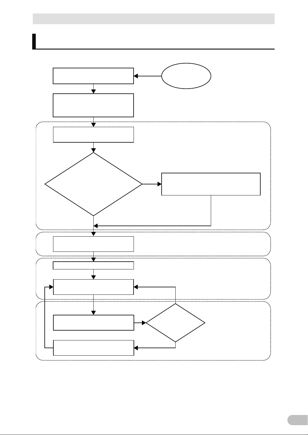
Procedure from installation to operation
3
Start
Read “Safety precautions”
Page 7
Remove the product from the
package and check the contents
1. Preparation
Perform installation and connection
2. Installation and connection
Are you using either of the
following functions?
- UPS monitoring software
- Contact signal
5. To perform shutdown processing of the
devices when a power failure occurs
6. Using the contact signal functions
Check the operation
3. Check and start operation
(Charge the battery *)
Operate
3. Check and start operation
* The UPS has been charged prior to shipment.
However, if it is left for a long period of time, it
may have self-discharged.
We recommend charging the UPS before using it.
Perform maintenance and inspection
4. Maintenance and Inspection
Replace the battery
4.2 Replacing the battery
The battery must
be replaced
Installation/connection
Preparation for operation
Operate
Perform maintenance
and inspection
Yes
No
No
Yes
Procedure from installation to operation
The procedure from installation to operation is shown below.
BU100RS
Page 5

Table of Contents
4
Table of Contents
Introduction .................................................................................................. 1
Procedure from installation to operation
............................................................. 3
Table of Contents ......................................................................................... 4
Safety Precautions ....................................................................................... 7
1 Preparation ........................................................................................... 16
1-1 Unpacking the product ................................................................................... 16
1-2 Checking the contents ................................................................................... 16
1-3 Related products ............................................................................................ 17
1-4 Name of each part ......................................................................................... 18
1-5 Diagram of the Input/output circuit block ....................................................... 20
2 Installation and connection ................................................................... 21
2-1 Installation ...................................................................................................... 21
2-1-1 Mounting the UPS to the rack (Communication/HUB rack - EIA 19" rack) ......................... 23
2-1-2 Stationary installation ......................................................................................................... 30
2-2 Connecting the equipment ............................................................................. 31
2-2-1 Connecting a device to the power supply output ............................................................... 31
2-2-2 Connecting a device to a terminal block ............................................................................ 33
2-3 Connecting the AC input ................................................................................ 36
3 Check and start operation .................................................................... 37
3-1 The name and function for the operation and display
3-1-1 Name of each part ............................................................................................................. 37
3-1-2 The meaning of each LED ................................................................................................. 37
3-1-3 Switch ................................................................................................................................ 38
3-1-4 Setting Switch .................................................................................................................... 38
3-1-5 Beep sound........................................................................................................................ 43
3-2 Checking the operation .................................................................................. 44
3-3 Start and stop procedures and basic operation ............................................. 47
3-3-1 Start and stop procedures .................................................................................................. 47
3-4 Interpreting beeps and displays ..................................................................... 49
3-4-1 Displays and beeps in normal operations .......................................................................... 49
3-4-2 Displays and beeps while testing ....................................................................................... 50
3-4-3 Displays and beeps during power failure or AC input error ................................................ 50
............................................... 37
BU100RS
Page 6

Table of Contents
5
3-4-4 Displays and beeps when there is an equipment failure .................................................... 51
3-4-5 Display and beep for battery replacement ......................................................................... 54
3-5 UPS operation mode settings ........................................................................ 55
3-5-1 Settable items and explanations ........................................................................................ 55
3-5-2 Settings .............................................................................................................................. 57
4 Maintenance and Inspection ................................................................. 61
4-1 Checking the battery ...................................................................................... 61
4-1-1 Battery life expectancy ....................................................................................................... 61
4-1-2 Self-diagnosis test ............................................................................................................. 61
4-1-3 Estimated backup time ...................................................................................................... 62
4-2 Replacing the battery ..................................................................................... 64
4-2-1 Notification that the battery needs to be replaced .............................................................. 65
4-2-2 Procedure for replacing the battery .................................................................................... 66
4-3 Replacing the fan ........................................................................................... 71
4-3-1 Fan replacement procedure ............................................................................................... 72
4-4 Cleaning ......................................................................................................... 74
4-5 Inspection of rack mounted condition ............................................................ 74
5 To perform shutdown processing of the devices when a power failure occurs
....................... 75
5-1 The outline on the UPS monitoring software ................................................. 75
5-1-1 UPS monitoring software function list ................................................................................ 75
5-1-2 The supported OS of the UPS monitoring software ........................................................... 77
5-2 When using the UPS monitoring software ..................................................... 77
5-2-1 What is the PowerAct Pro .................................................................................................. 77
5-2-2 What is the Simple Shutdown Software ............................................................................. 78
5-2-3 How to connect .................................................................................................................. 78
6 Using the contact signal functions ........................................................ 80
6-1 Contact signal functions ................................................................................. 80
6-1-1 Type of Output signals ....................................................................................................... 80
6-1-2 Type of Input signals .......................................................................................................... 80
6-1-3 Contact signal port (female D-SUB 9 pin) .......................................................................... 81
6-1-4 Remote ON/OFF port ........................................................................................................ 81
6-1-5 Contact Signal ratings ........................................................................................................ 81
6-1-6 Contact Signal circuit ......................................................................................................... 81
6-1-7 Example of the use of the Contact Signal circuit ................................................................ 82
BU100RS
Page 7

Table of Contents
6
6-1-8 Precautions and notes for the use of the Contact Signal ................................................... 82
7 Troubleshooting .................................................................................... 83
8 Note of Chinese .................................................................................... 84
9 References ........................................................................................... 93
9-1 Specifications ................................................................................................. 93
9-2 Dimensions .................................................................................................... 94
9-3 Battery life ...................................................................................................... 98
9-4 China RoHS Information ................................................................................ 99
BU100RS
Page 8
7
Safety Precautions
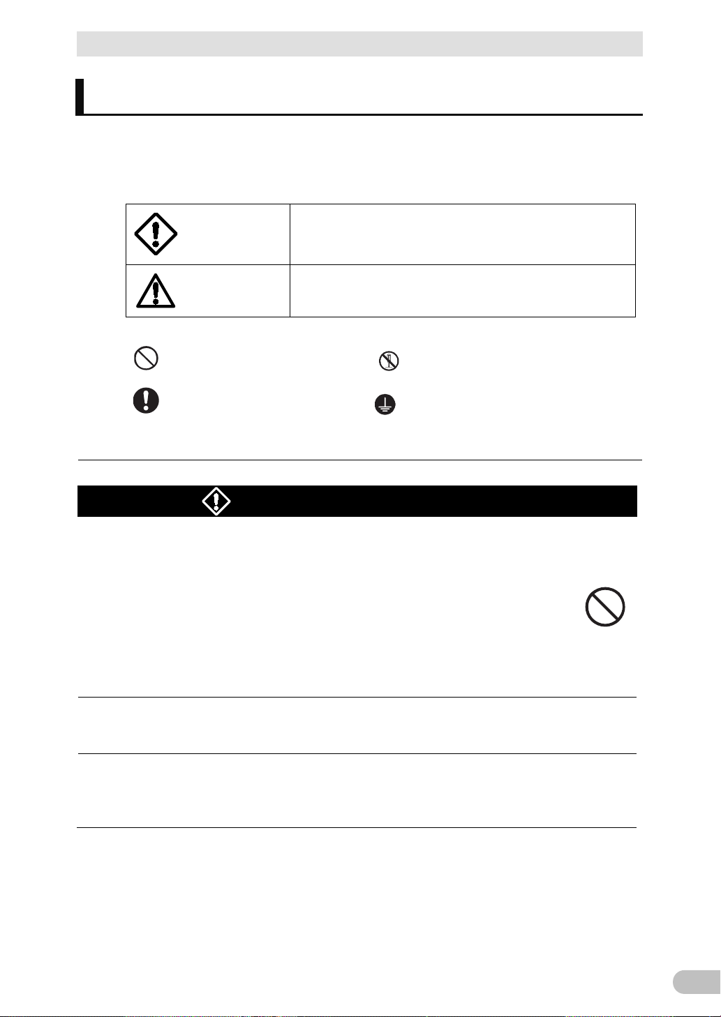
● The safety symbols and their meaning used in this manual are as follows:
Do not use this unit when very high reliability and safety are required as
(For example, essential computer systems and main
Applications with the same level of importance.
This is a category C2 UPS product. In a residential environment, this
required to take additional measures.
actions.
Safety Precautions
Safety precautions
Warning
Caution
* Property damage means damage to houses/household effects, livestock, and pets.
: Indicates prohibition. For example,
: Indicates obligation. For example,
Note that events categorized as a caution required matter also may cause more serious results
under certain conditions.
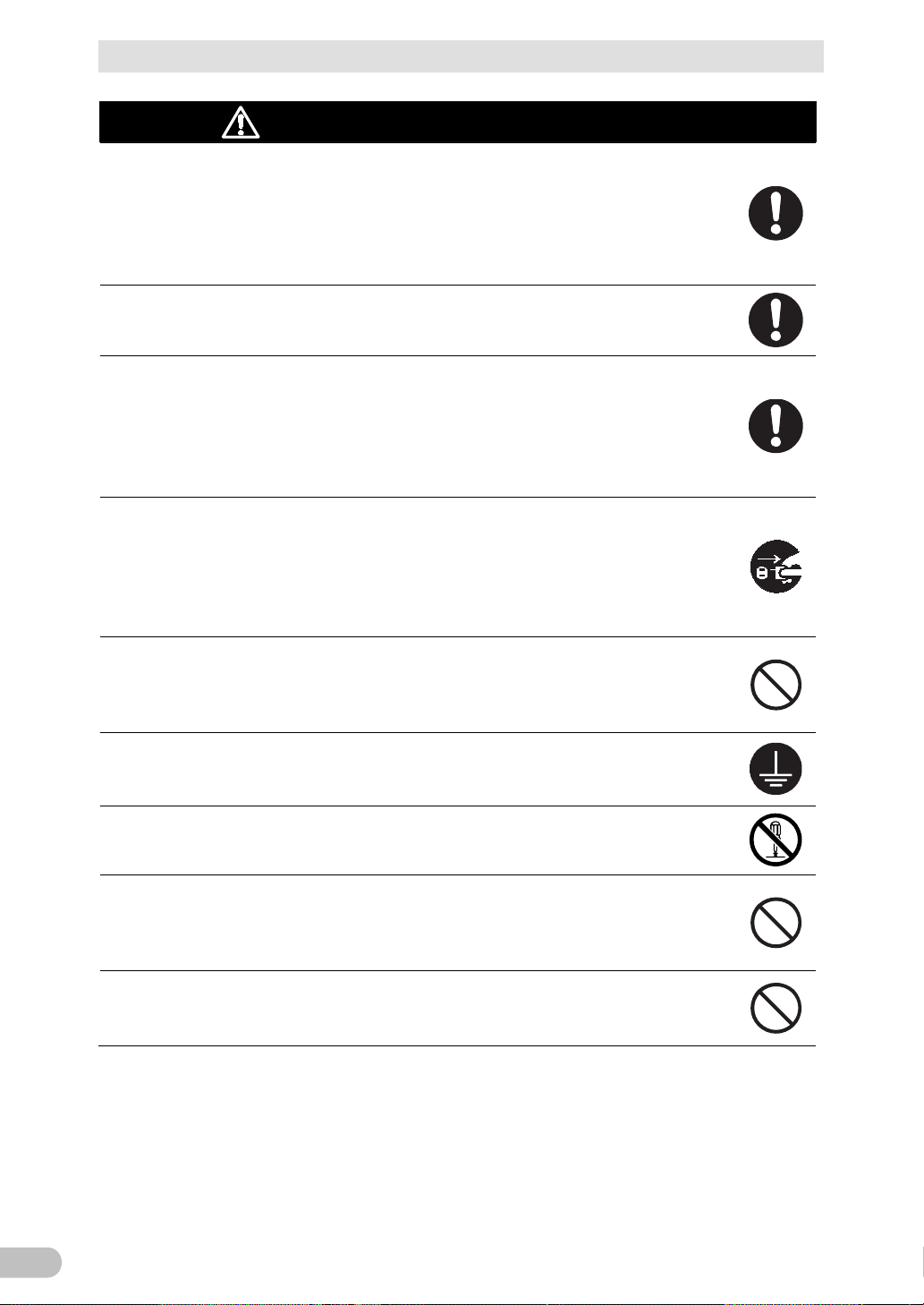
Warning
listed below. This unit is designed and manufactured for use with OA
equipment such as personal computers.
● Medical equipment or system that may cause death directly.
● Applications that directly affect the safety of people (For example, the operation and
control of cars and elevators).
● Applications in which a failure of the unit may cause significant damage to the
society and public.
communication equipment.)
●
Important information for safe operation is described.
Be sure to read it before installation and start of use.
Misuse may cause death or serious injury.
Misuse may cause injury or property damage.
indicates that disassembly is prohibited.
indicates that grounding is necessary.
(for use of this product)
product may cause radio interference, in which case the user may be
This is a Class A product based on the standard of the VCCI Council. If
this equipment is used in a domestic environment, radio interference
may occur, in which case, the user may be required to take corrective
BU100RS
Page 9
Safety Precautions
8
Carry the unit considering its weight and balance, and place it on a
Keep plastic package bags out of reach of children.
The unit may fail.
When an abnormality (unusual sound or smell) occurs, turn OFF the
to stop the output, and stop the supply of
outlet shall be installed near the
When performing maintenance on the connected devices, follow the above
instructions to ensure safety.
Do not connect devices such as dryers, some solenoid valves, etc.,
Provide secure grounding.
Do not install the unit in other than specified orientations.
If you install the unit in an orientation other than specified, the unit cannot be
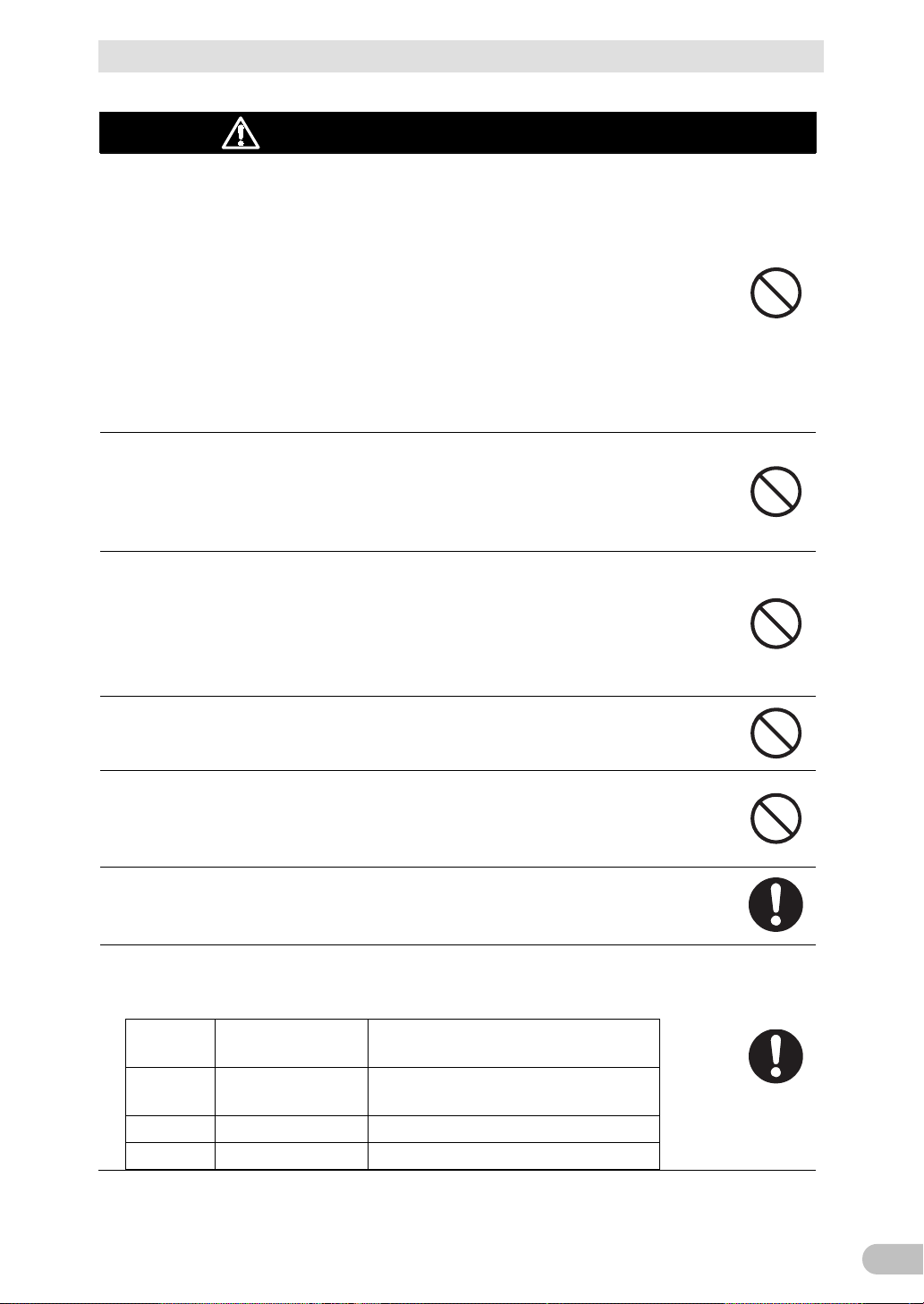
Caution
(for installation and connection)
stable and robust base.
● Dropping or toppling the unit may cause injury.
● The approximate weight of the unit is 13 kg.
● If you drop the unit, stop using it and have it inspected and repaired.
For repair, contact us.
● Children may suffocate if they place their heads into plastic bags.
Make sure to connect the unit’s AC input to a commercial power source
with rated input voltage (100 VAC,110VAC,115VAC,120VAC) and 50/60 Hz
frequency.
● Connecting to a commercial power source with a different rated input voltage or
frequency may result in a fire.
●
unit’s “Power” switch
commercial power. The socketequipment and shall be easily accessible.
●
which have a half-wave rectifier that allows only half-cycle AC power to
flow through.
● Overcurrent may damage the UPS.
● Connect the terminal to a commercial power source and ground it. A failure or leak
that occurs when the unit is not properly grounded may result in electric shock.
Do not disassemble, repair, or modify the unit.
● Doing so may cause an electric shock or a fire.
● Dropping or toppling the unit may cause injury.
●
protected from a battery fluid leakage.
Do not use the unit where the maximum temperature exceeds 40°C.
● The battery deteriorates rapidly.
● Doing so may cause a failure or malfunction of the unit.
BU100RS
Page 10
Safety Precautions
9
Installation or storing the unit in such a place may cause a fire.
When you use plug strip and other plugs to connect additional devices,
Leave at least 5 cm of space between the vent and the wall.
When installing the unit on a rack, place it on the bottom shelf of a rack.
diameter
terminal-block-cover mounting screw
M4
1.23±0.15 N·m
Terminal-block-cable mounting screw
Caution
(for installation and connection)
Do not exceed the ranges specified for environmental conditions during
use/storage.
Do not install or store the unit in the places listed below.
● Do not store in places where the humidity is lower than 10% or higher than 90%.
● Do not use the unit in places where the ambient temperature is lower than 0°C or
higher than 40°C. (With no condensation)
● Do not use in places where the humidity is lower than 25% or higher than 85%
● Do not install/store the unit in closed places such as cabinets with no clearance,
places where there is flammable or corrosive gas, places with large amounts of
dust, places exposed to direct sunlight, places exposed to shock or vibration, salty
or wet places, or outdoors.
●
do not connect devices that exceed the current capacity of the available
plugs.
● The current protection of the unit may operate, which may stop the output.
● The wiring of the plug strip heats up, which may cause a fire.
Do not pinch or sharply bend the cable.
Do not fold or knot the cable.
● Doing so may cause the cable to be damaged or heated, which may cause an
electric shock or a fire.
● If the cable is damaged, stop using the unit and have the cable repaired.
● For repair, contact us.
All of the included accessories are designed to be used with the unit. Do
not use the accessories with other devices.
● Doing so may compromise the safety of devices.
Do not block the air vents (front, rear, and sides).
● Doing so will cause the internal temperature to rise, which may cause the unit to fail
and the battery to deteriorate.
●
● Injury may result if the unit falls.
To attach a screw, tighten it with a specified torque.
● Failure to do so might cause a tightening error and result in a fire or fall.
(Table 1) Specified tightening torque
Nominal
M3 0.55±0.1 N·m
M5 2.75±0.2 N·m Rack mounting screw
Tightening torque
Type of screw used
Ear-bracket mounting flat head screw,
BU100RS
Page 11
Safety Precautions
10
Do not allow the unit to come in contact with water.
temperature
under standard use conditions and are not
If you notice an abnormal sound or smell, smoke, or leaking fluid,
A readily accessible disconnect device shall be incorporated external to the
your doctor.
Caution
(for installation and connection)
This product must be mounted to or removed from a rack by two people.
● This product is a heavy object. There is a risk of injury if it overturns or falls.
Caution
(for use)
If you drop the unit, stop using it.
● Doing so may cause an electric shock or a fire.
● If the unit becomes wet or is dropped, immediately stop using it, disconnect the AC
input from the wall outlet (commercial power source) and have it inspected and
repaired.
● For repair, contact us.
When the battery is dead, replace it immediately or stop using the unit.
● Continuing the use of it may cause fire or electric shock due to liquid leaks.
Ambient
25°C 5 years
30°C 3.5 years
35°C 2.5 years
40°C 5 years
Expected life
* The values in the table are the expected life
guaranteed.
Using a dry cloth, periodically wipe the dust from the "AC input" plug
and power supply output receptacles.
● Accumulated dust may cause a fire.
● Before wiping off dust, stop all connected devices and the unit, and stop the supply
of commercial power.
Do not use the unit in a closed place and do not cover the unit.
● Doing so may cause abnormal heating or a fire.
● Depending on the operating environment, hydrogen gas may be generated from the
battery, resulting in a rupture or explosion. Ventilate the area around the unit.
immediately turn OFF the unit’s “Power” switch and stop the supply of
commercial power.
● Using the unit under such conditions may cause a fire.
● If you notice such a condition, stop using the unit and contact us for inspection and
repairs.
●
equipment.
If fluid (dilute sulfuric acid) leaks from the interior, do not touch the fluid.
● Doing so may cause blindness or burns.
● If the fluid contacts your eyes or skin, wash it out with lots of clean water and consult
BU100RS
Page 12
Safety Precautions
11
ven when the inner control circuit is
If you want to stop the output, either stop the source of commercial
When maintaining the connected equipment, turn OFF the unit’s
output of his unit does not stop and power is supplied from the receptacle.
If fluid (dilute sulfuric acid) leaks from the interior, do not touch the fluid.
Caution
Do not place any objects on the unit, and do not drop heavy objects onto
the unit.
● Doing so may cause distortion/damage to the case or a failure of the internal circuit,
which may cause a fire.
The unit is equipped with a bypass circuit which is able to supply electric
power to connected devices e
broken down by defects or malfunctions.
power.
● Output is continuing even when all indicators of the front panel are off.
● Output ON/OFF cannot be controlled with the “Power” switch on the front panel.
Do not sit or stand on top of the product, use it as a step ladder, or lean
against it.
● Doing so may cause the unit to fail or to fall over and result in injury.
Periodically check that the screws are not loose and that there is no gap
between metal sheets.
● A loose screw may cause damage to the product.
Caution
(for use)
(for maintenance)
“Power” switch to stop the output, and stop the supply of commercial
power.
● Even if commercial power to the UPS is stopped while it is in operation, the power
Do not disassemble, repair, or modify the unit.
● Doing so may cause an electric shock or a fire.
● Doing so may cause blindness or burns.
● If the fluid contacts your eyes or skin, wash it out with lots of clean water and consult
your doctor.
Do not throw the unit into fire.
● The lead battery in the unit may explode, or leak dilute sulfuric acid.
Do not insert metal objects into the power supply output receptacle of
the UPS.
● Doing so may result in electric shock.
Do not insert metal objects into the battery connectors.
Do not short between the connector terminals.
● Doing so may result in electric shock.
BU100RS
Page 13
Safety Precautions
12
Perform replacement on a stable and flat place.
Product model: BAB100R
If fluid (dilute sulfuric acid) leaks from the battery, do not touch the fluid..
Some electrical energy still remains inside the spent battery.
Do not dispose of batteries in a fire.
Do not use a new battery and an old battery at the same time.
Disconnect charging source prior to connecting or disconnecting battery
maintenance to reduce
Servicing of batteries should be performed or supervised by personnel
Caution
● Handle the battery carefully so that you do not drop it.
● Risk of injury due to falling, or burns due to fluid leakage (dilute sulfuric acid).
(for battery replacement)
Use a specified battery for replacement.
● Not doing so may cause a fire.
● Battery pack for:
Do not replace the battery in a place where there is flammable gas.
● Spark may occur when connecting the battery, which may cause an explosion or
fire.
● Doing so may cause blindness or burns.
● If the fluid contacts your eyes or skin, wash it out with lots of clean water and consult
your doctor.
Do not disassemble or modify the battery.
● Doing so could cause dilute sulfuric acid leak, which could cause blindness and
burns.
Do not drop the battery and do not expose it to strong impact.
● Dilute sulfuric acid may leak.
Do not short the battery with metal objects.
● Doing so could cause an electric shock, fire or burn.
●
● The batteries may explode.
● Dispose of used batteries according to the instructions.
● Dilute sulfuric acid may leak.
● A battery can present a risk of electrical shock and high short circuit current.
● Contact with any part of a grounded battery can result in electrical shock.
● The following precautions should be observed when working on batteries:
a. Remove watches, rings, or other metal objects.
b. Use tools with insulated handles.
c. Wear rubber gloves and boots.
d. Do not lay tools or metal parts on top of batteries.
e.
terminals.
f. Remove battery grounds during installation and
likelihood of shock. Remove the connection from ground if any part of the
battery is determined to be grounded.
●
knowledgeable of batteries and the required precautions.
Keep unauthorized personnel away from batteries.
BU100RS
Page 14

Safety Precautions
13
Ne pas ouvrir ni détériorer les batteries.
Utilisez les batteries conformément aux instructions.
Les batteries peuvent présenter un risque de choc electrique avec un fort courant
ATTENTION
Les fuites d'électrolyte sont dangereuses pour la peau et les yeux.
Protéger les batteries du feu. Risque d'explosion des batteries.
de court circuit.
Les précautions suivantes doivent être suivie lors de l'intervention sur les batteries :
a : Retirer les montres, bagues et autre objets en métal
b : Utilisez des outils à manche isolé
c : Utilisez des gants et des chaussures isolant
d : Ne pas laisser des outils ou des objets métalliques proches des batteries
e : Déconnecter le chargeur avant de connecter ou de déconnecter les batteries
f : Déterminer si la pile est mise à la terre. Si elle est mise à la terre, effectuer la deconnection. Le
contact avec une pile mise à la terre peut créer un choc électrique. Ceci sera réduit si cette mise
à la terre est supprimée pendant installation et maintenance.
BU100RS
Page 15

Safety Precautions
14
■ Before using
Charge the battery soon after purchasing the unit.
● If you do not use the unit for a long time after the purchase, the battery may
deteriorate and the battery may become unusable.
● The battery can be charged once the AC input is connected to commercial power.
When moving the unit from a cold place to a warm place, leave it for several
hours before using it.
● If the unit is promptly turned ON after being moved to a warmer place,
condensation may form inside the unit and cause it to fail.
Take measures for handling unforeseen accidents, such as data backup and
system redundancy.
● The output may stop when there is failure in the UPS.
■ Connecting
Do not connect a page printer (such as a laser printer) to the unit.
● The unit repeatedly and frequently switches between Commercial Power Mode
and Battery Mode, which may shorten the life of the battery.
Notes
● The page printer has a large peak current, so an excess of the connection
capacity or a power failure due to instantaneous voltage drop may be detected.
If this unit is used for an inductive device such as a coil, transformer or motor,
check the operation beforehand.
● With some types of devices, the effect of inrush current may cause this unit to
stop operating properly.
Check system operation beforehand if the unit is used in combination with a
device whose power supply voltage and frequency fluctuate widely, such as a
generator.
● If the generator’s output voltage/frequency falls out of the unit's input
voltage/frequency range, the unit will enter Battery Mode.
Do not short the output lines of the unit to each other, and do not short the
output lines to the ground.
● The unit may fail.
In the event you transfer or sell this unit to a third party, please include all of
the documentation that came with the unit. This is to ensure that the unit is
used in line with the conditions described in the included documentation.
● This manual contains important safety-related information. Please read and
understand the contents of the manual before beginning operation. If this manual
is misplaced, download the manual from our website.
BU100RS
Page 16

Safety Precautions
15
Pb
■ Using
Before stopping the commercial power to the unit, turn OFF the “Power”
switch of the unit.
● The unit enters Battery Mode when commercial power is stopped.
Do not use for an application that frequently requires Battery Mode.
● The battery will deteriorate and fail to maintain the specified backup time.
Do not connect the AC input terminal of the unit to its Power
Supply Output terminal during the Battery Mode.
● The unit may fail.
This unit uses lead acid batteries.
● Which are a valuable recyclable resource. Please recycle.
Before performing a withstand voltage test or insulation resistance test,
remove the input surge protection GND screw from the back of the unit. Before
using the product, be sure to attach an "input surge protection GND" screw
and tighten it with the tightening torque (1.23
● Performing the withstand voltage test with the ground wire connected may
damage the surge absorption element built into the power supply input circuit.
■ Storing
Storing the battery in UPS, charge for at 4 hours, then turn off the "Power"
switch of the unit.
Recharge the battery for at least 4 hours every 6 months when the storage
temperature is 25°C or less, or every 2 months when the storage temperature is
40°C or less.
● The battery self-discharges even when it not being used, and it goes into
overdischarge state if it is left for a long period of time. The backup time may
become shorter or the battery may become unusable.
±0.15 N・m).
BU100RS
● We recommend keeping the temperature 25°C or less when storing the unit for
long periods of time.
● Turn OFF the unit’s “Power” switch when storing it.
Do not install or store the unit in a place exposed to direct sunlight.
● The rise of temperature may cause the built-in battery to deteriorate rapidly and
become unusable.
Page 17
1 Preparation
16
● Dropping may cause injury.
BU100RS
Precautions (Japanese/English/Chinese/French)
1
Rubber feet
4 per set
Connection cable (RS232C)
1
Remote ON/OFF connector
1
Registration post card
1
Registration information sheet(Japanese)
1
Replacement service take-up request form
1
Serial number label
1
Battery replacement date label
1
Label (How to determine operating status)
1
Product warranty (Japanese)
1
Ear bracket
2
Ear-bracket mounting flat head screw (M3)
8
Rack mounting screw (M5)
8
Rack cage nut (M5)
8
3P-2P conversion plug
1
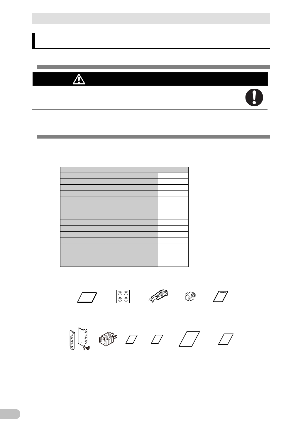
<Accessories related to main unit>
Precautions
(Japanese/
English/Chinese)
Rubber feet
Communication
cable (RS232C)
(Approx. 2.2m)
Remote
ON/OFF
connector
Registration
postcard
Ear bracket /
screws
Serial
number
label
3P-2P
conversion
plug
Battery
replacement
date label
Label (How to
determine
operating status)
Product
warranty
1-1 Unpacking the product
1 Preparation
1-1 Unpacking the product
Caution
(for installation and connection)
The approximate weight of the unit is 13 kg. Note the weight when
unpacking and transporting the unit.
Open the package box and take out the UPS and accessories.
1-2 Checking the contents
Check whether all the package contents are included and there is no damage found on
their appearance. If you should notice defects or anything wrong, contact us; OMRON
Electronic Systems & Equipments Customer Support Center.
BU100RS
Page 18
1 Preparation
17
1
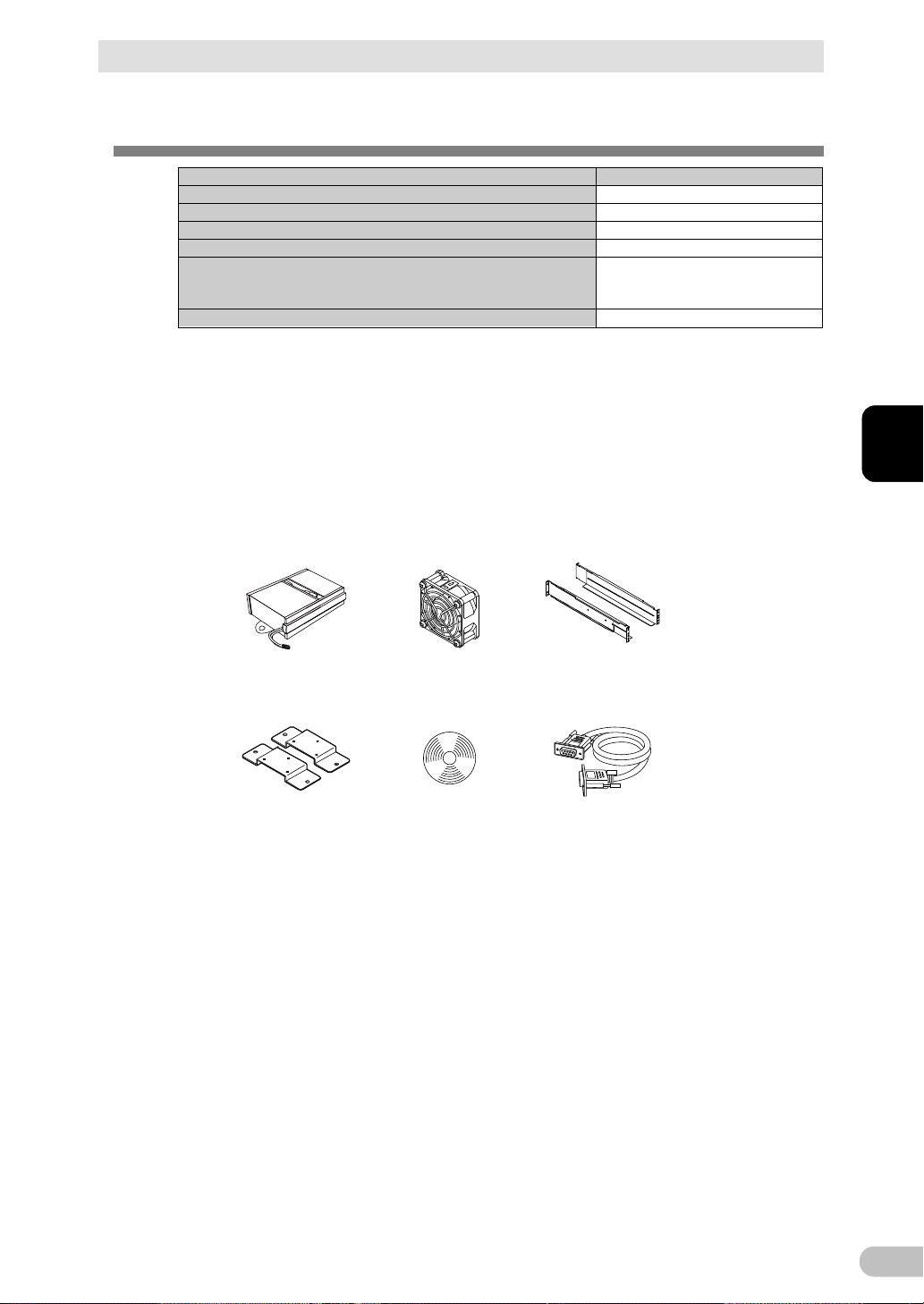
Description
Model Number
Replacement battery pack
BAB100R *1
Replacement fan
BAF100R
Support angles compatible with EIA/JIS 19-inch racks
BAP100RS *2
Vertical floor mounting bracket
BAP100R
CD-ROM
and UPS service driver are included.
PA0 1
Optional cable for UPS service
BUC26
<
Related products
>
Replacement
battery pack
Replacement fan Support angles
compatible with EIA/JIS
19-inch racks
Vertical floor
mounting bracket
CD-ROM
Optional cable for UPS
service BUC26
1-3 Related products
1-3 Related products
"PowerAct Pro" UPS monitoring software, “Simple Shutdown Software",
*1 Battery pack of BAB100R information:
a) Valve regulated lead-acid battery x 2p
b) Nominal voltage of total battery string: 24VDC
*2 The length is from 487 to 891mm.
Ear brackets (2p) and ear-bracket mounting flat head screws (M3 x 6p) are provided with an
optional support angle.
BU100RS
Page 19
1 Preparation
18
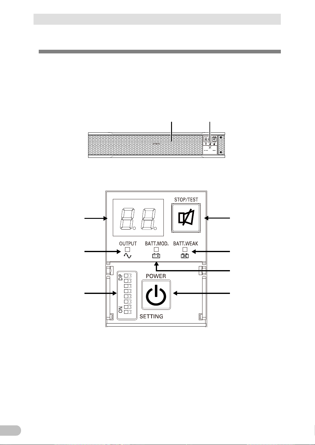
<BU100RS>
(Air vent) (Operation panel)
1 2 3 4 5 6 7 8
A
B
E
G
D
C
F
A: Status indicator
B: “Power supply output” LED
C: “Battery mode” LED
D: “Battery replacement” LED
E: “Setting switch”
F: “Power” switch
G: “Buzzer Pause/Test” switch
<Enlarged view of the operation panel>
1-4 Name of each part
1-4 Name of each part
This section describes the name of each part of the UPS.
For information on the function of each part, refer to “2 Installation and connection” and “3
Check and start operation” that provides the details.
● Front view
BU100RS
Page 20
19
1
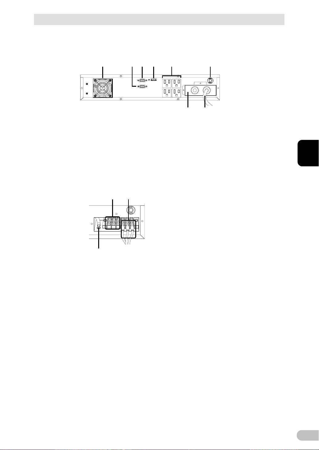
● Rear view
<BU100RS>
A B C D
E F
H G
A: Cooling fan (air vent)
B: RS232C port
C: Contact signal port
D: Remote ON/OFF port
E: Power supply output receptacles
(Backup is performed during power failure.)
F: Input protection
G: AC input plug
H: Terminal block cover
IJ
K
I: AC input plug
J: AC output terminal block
K: Input surge protection GND
<H: Input terminal block cover is dismounted>
1 Preparation
1-4 Name of each part
BU100RS
Page 21
1 Preparation
20
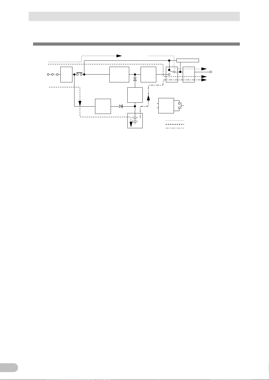
Noise
filter
Input
overcurrent
protection
AC100V
input
Power
supply
relay
Charging
circuit
Rectifier
(high power
factor
converter)
Step-up
converter
Inverter
(sine
wave)
Filter
Commercial
power bypass
output
Output
switching
Control
circuit
Power supply
switch
Battery
At startup/capacity exceeded/error
During Line mode
During Battery mode
Power
supply
output:
AC 100V
Electoronic switch
1-5 Diagram of the Input/output circuit block
1-5 Diagram of the Input/output circuit block
BU100RS
Page 22

2 Installation and connection
21
2
2 Installation and connection
2-1 Installation
Install the UPS.
For cautions when installing the UPS, refer to “Caution (for installation and connection)”
shown in the "Safety precautions" of the beginning of this manual.
The UPS permits the following installing methods. Choose the one best suited for the
environment.
Notes
● Before installing this device, make a record of the serial number of this device.
The product serial number is required when contacting us about the device. The
serial number (S/N) is inscribed on the bottom left side of the rear panel. The
product serial number is inscribed on the bottom left side of the rear panel. The
product serial number label is also included.
● Allow sufficient space at the back for the UPS unit and Input power cable, and AC
input cables of the connected devices.
2-1 Installation
BU100RS
Page 23
2 Installation and connection
22
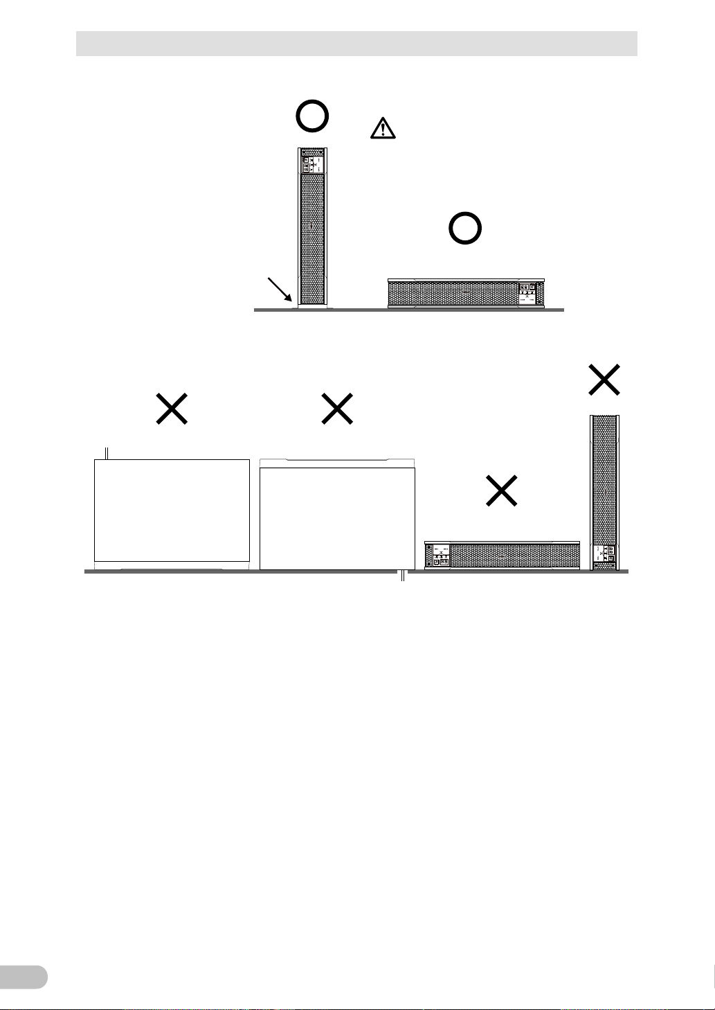
(Air vents are facing upward)
Ba careful not to get your fingers
caught when arranging the unit.
Correct Positions
Note: For vertical installation, be
sure to use optional verti
cal floor mounting brackets
(BAP100R).
Incorrect Positions
2-1 Installation
<BU100RS>
BU100RS
Page 24
2 Installation and connection
23
2
Do not use the UPS in an environment where the highest temperature
● Otherwise, this product may fail or malfunction.
flat head screw
M5
2.75± 0.2 N·m
Rack mounting screw
2-1 Installation
2-1-1 Mounting the UPS to the rack (Communication/HUB
rack - EIA 19" rack)
Mount the Uninterruptible Power Supply (UPS). For precautions on mounting, refer to the
"CAUTION" below.
Reference
* About load capacity
We are now asking the rack manufacturer about the load capacity of each of the racks
below. We will continue to check racks of other manufacturers and publish the results as
needed on our Website. Check the latest information on our Website.
- FS series by Nitto Kogyo Corporation
- TH series by Nitto Kogyo Corporation
Caution
(for installation and connection)
To use a rack, check its load capacity.
● The load capacity for 2U must be up to 30kg.
becomes more than 40°C.
● Otherwise, the battery may deteriorate rapidly and cause fires.
This product must be mounted to or removed from a rack by two people.
● This product is a heavy object. There is a risk of injury if it overturns or falls.
To mount the product into a rack, be sure to use the ear brackets and
screws in the product package, and tighten the screws with the torques
specified for them.
● Weight of the unit: Approx. 13kg
● If the screws are not tightened with the torques specified for them, the brackets may
become so loose that the UPS can be detached, fall, and eventually cause injuries.
(Table 1) Specified tightening torque
Nominal diameter Tightening torque Type of screw used
M3 0.55± 0.1 N·m
Ear-bracket mounting
● Using screws longer than the screws provided as accessories for mounting the
enclosure may cause damage internally.
● Using screws other than the screws provided as accessories may cause a fall
accident due to insufficient strength.
To mount to or remove from the rack, secure a space to put your hands
in so as to hold the UPS.
● If there is no sufficient space, the UPS cannot be mounted correctly or may fall.
BU100RS
Page 25

2 Installation and connection
24
Be sure to mount the UPS into the bottom shelf of a rack.
To mount or remove, do not apply load to the product such as pulling a
2-1 Installation
Caution
● There is a risk of injury if the product falls.
● This product is a heavy object. If it is mounted into the top part of the rack and falls,
it may cause damage to other equipment.
To mount into a rack, tighten the screws well so that there is no gap
between the ear brackets of the product and the rack.
● A gap may cause the product to fall.
cable.
● Applying load may cause the product to fall.
(for installation and connection)
Notes
Periodically check that the screws are not loose and that there is no gap
between metal sheets.
● A loose screw may cause damage to the product.
If mounting the UPS with both front and rear mount rails, use a 19" rack
support angle mounting bracket set (BAP100RS).
● For details about how to mount UPS, refer to the instruction manual for
BAP100RS.
BU100RS
Page 26
2 Installation and connection
25
2
2-1 Installation
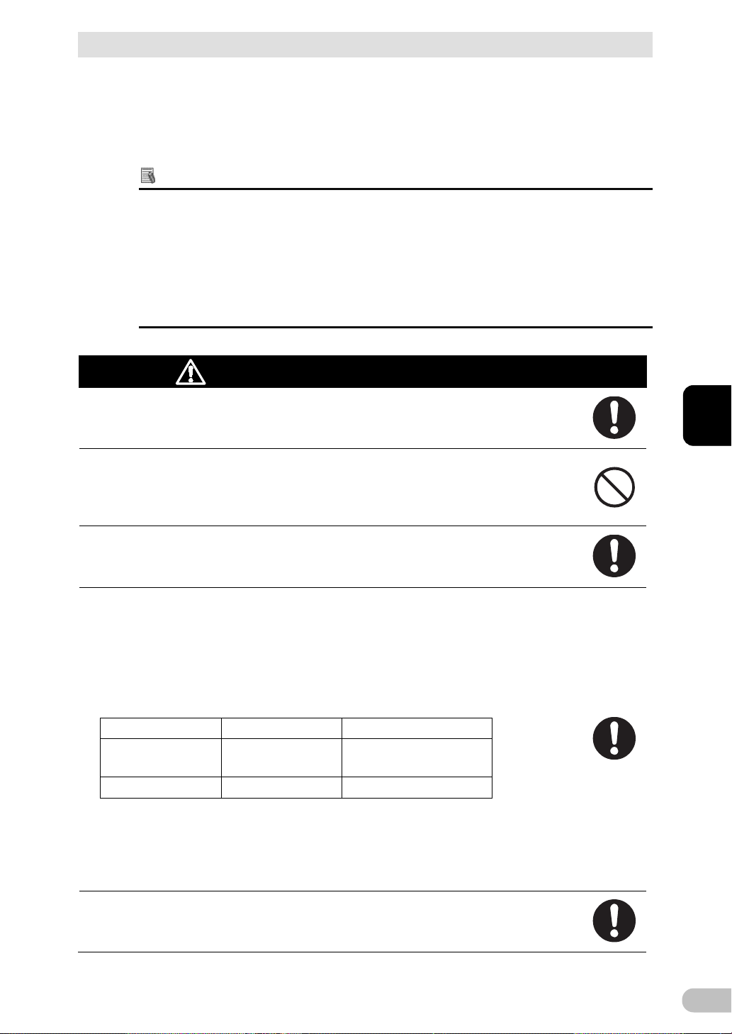
■How to mount to the rack
1. Fix the ear brackets on the left and right sides of the UPS by using eight ear-bracket
mounting flat head screws (M3) provided as accessories (four on each side) with the
torque specified for them (0.55±0.1N・m).
<Horizontal installation>
Reference
This section explains how to mount the UPS into a rack for horizontal installation.
For details about vertical installation, refer to pages 27 to 29.
* If the rack's posts have no female threads, attach rack cage nuts in advance.
BU100RS
Page 27
2 Installation and connection
26
2-1 Installation
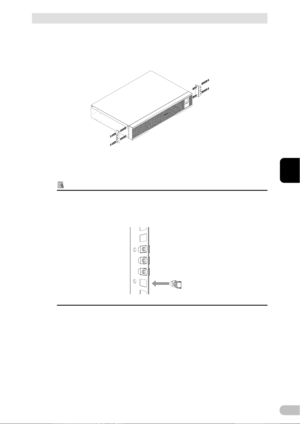
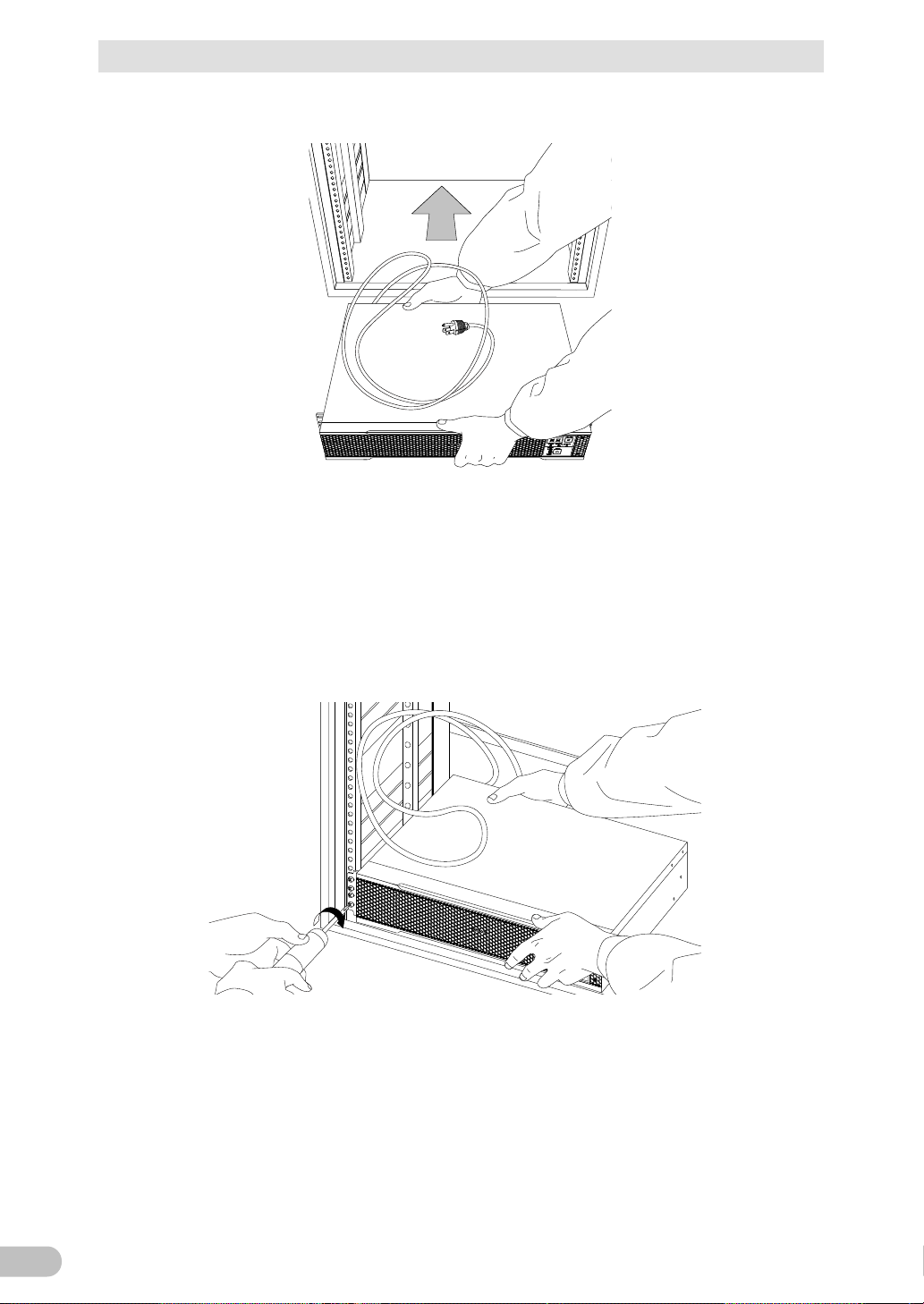
2. Put the UPS in front of the rack, and hold its front and rear sides.
3. Align the rack's mounting holes with the ear brackets' holes and fix the ear brackets
using eight rack fixing screws (M5) to the rack with the specified torque (2.75±0.2N・m).
* This work must be done by two people.
Since the front side only is being held, the rear side may slightly tilt downward while
tightening the screws.
So, hold the UPS with the rear side being lifted so that it becomes level to tighten the
screws.
BU100RS
Page 28
2 Installation and connection
27
2
2-1 Installation
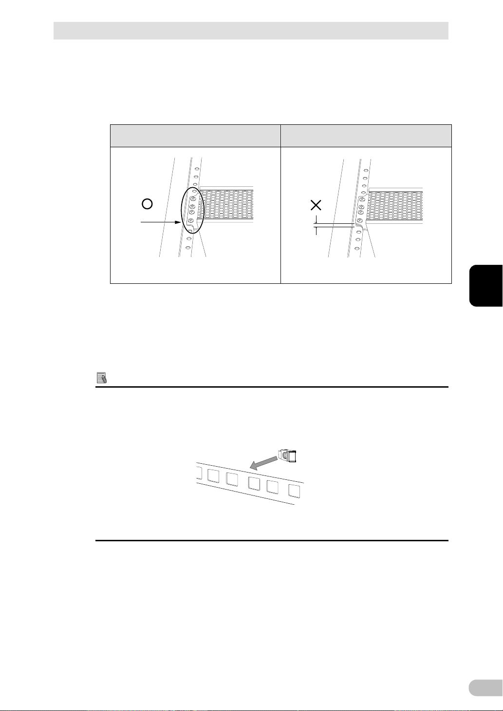
4. Ensure that the screws are tightened.
As shown in the figure below, check that there is no gap between the rack and each ear
bracket.
If a gap exists, as in step 3, while lifting the rear side, make the UPS level and tighten
the screws again to eliminate the gap.
Correct installation Incorrect installation
No gap
* Proceed to step 5 if there has been no problem so far.
Gap
<Vertical installation>
Reference
This section explains how to mount the UPS into a rack for vertical installation.
For details about horizontal installation, refer to pages 25 to 27.
* If the rack's posts have no female threads, attach rack cage nuts in advance.
BU100RS
Page 29
2 Installation and connection
28
1 2 3 4 5 6 7 8
POWER
OUT PU T
BATT .MO D. BATT.WEAK
STOP/TEST
2-1 Installation
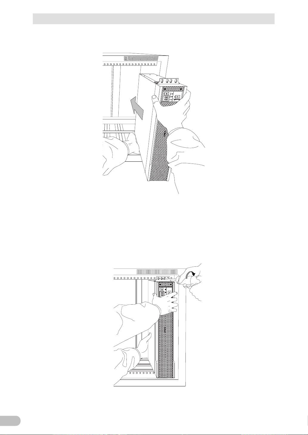
2. Put the UPS in front of the rack, and hold its front and bottom sides.
3. Align the rack's mounting holes with the ear brackets' holes, and fix the ear brackets
using eight rack fixing screws (M5) to the rack with the specified torque (2.75±0.2N・m).
* This work must be done by two people.
Since the front side only is being held, the rear side may slightly tilt downward while
tightening the screws.
So, hold the UPS with the rear side being lifted so that it becomes level to tighten the
screws.
BU100RS
Page 30
2 Installation and connection
29
2
2-1 Installation
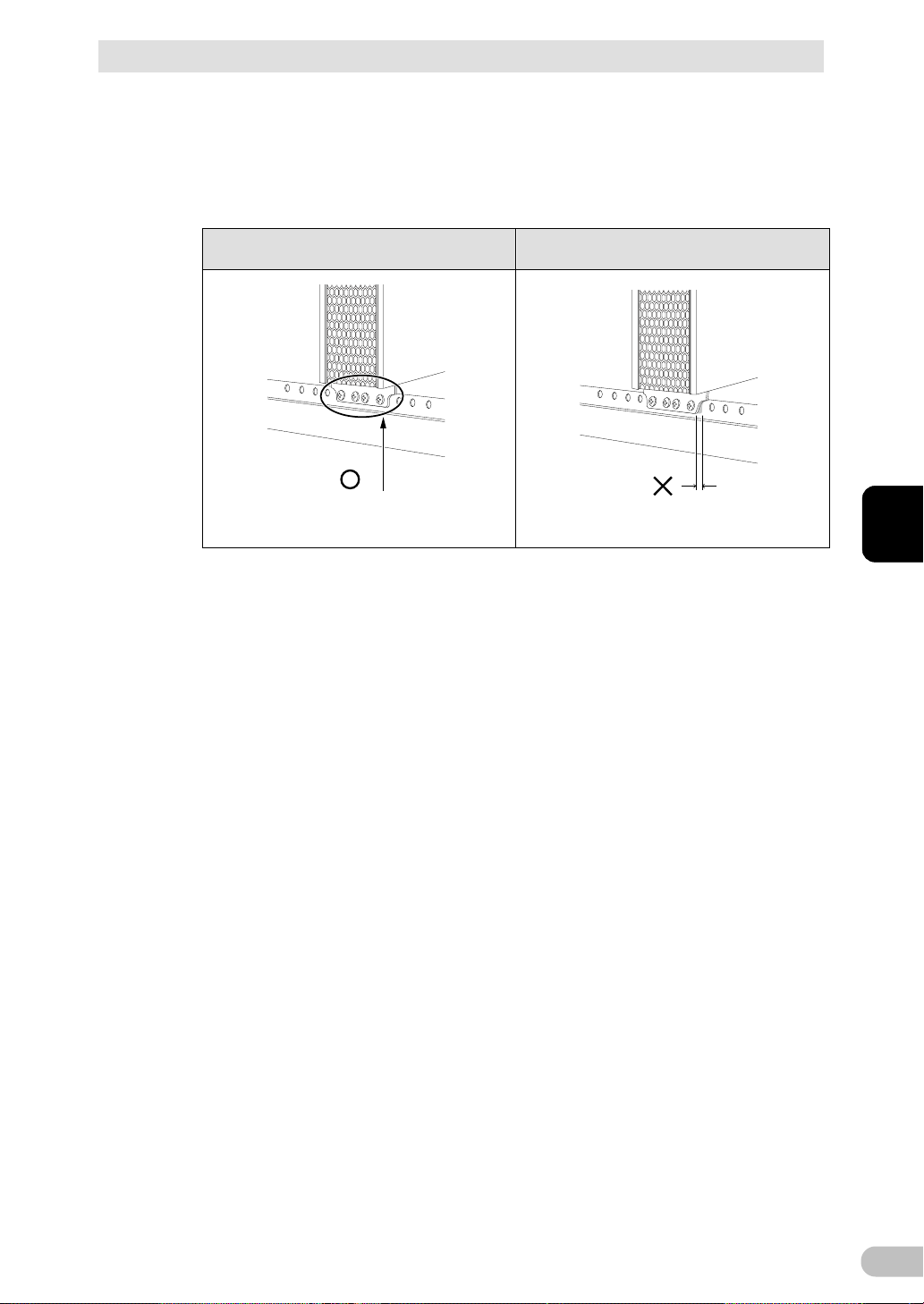
4. Ensure that the screws are tightened.
As shown in the figure below, check that there is no gap between the rack and each ear
bracket.
If a gap exists, as in step 3, while lifting the rear side, make the UPS level and tighten
the screws again to eliminate the gap.
Correct installation Incorrect installation
No gap
* Proceed to step 5 if there has been no problem so far.
Gap
5. Periodically check that the screws are not loose and that there is no gap between metal
sheets.
If a gap exists, while holding the whole UPS, tighten the screws again with the specified
tightening torque (2.75±0.2N・m).
Note: A loose screw may cause damage to the product.
Then, the installation process is completed.
BU100RS
Page 31

2 Installation and connection
30
2-1 Installation
2-1-2 Stationary installation
Perform installation only as shown in the diagrams below.
● Horizontal installation
Attach the included rubber feet for horizontal installation and position the unit horizontally.
For stationary horizontal installation, make sure that this product does not slide or fall.
● Upright installation
Fix the brackets (2p) using M3 flat head screws (6p) provided with the product option
(model BAP100R) to the UPS with the specified torque (0.55±0.1N・m).
BU100RS
Page 32

31
2
2-2 Connecting the equipment
Do not connect devices, rated voltage is not 100-120VAC.
Wall outlet
(commercial power source)
Computer peripheral devices
PC
Computer peripheral devices
External HDD
2 Installation and connection
2-2 Connecting the equipment
Caution
● The rated output voltage of this device is 100-120VAC .
● Overcurrent may damage the connected devices.
(for connection)
2-2-1 Connecting a device to the power supply output
For cautions when connecting the UPS, refer to “Caution (for installation and connection)”
shown in the “Safety precautions” of the beginning of this manual.
1. Disconnect the AC Input Plugs of all devices you want to back up such as your PC and
modems from a wall outlet (commercial power source).
2. Connect devices you want to back up to the Power Supply Output Receptacles of the
UPS.
・ If you need more output receptacles than those of the UPS, purchase a plug strip and
use it for extra output receptacles.
BU100RS
Page 33

2 Installation and connection
32
Connect it directly. Connect it directly. Connect the plug directly.
Plug of connected
device
Plug of connected
device
Plug of connected
device
Connect the grounding wire of
connect devices to the "AC
output GND" terminal or "AC
input ground" terminal of the
UPS.
Connect the grounding wire to the
"AC output GND" terminal or "AC
input ground" terminal of the
UPS.
Connect the conversion plug.
Conversion
adaptor with a
ground terminal
Connect the grounding wire to a
ground terminal of a conversion
adaptor with a ground terminal.
2-2 Connecting the equipment
When the connected device has a 2-pin AC input plug, it can be connected directly to
・
the power supply output receptacle. When using a 2-pin input plug with a grounding
wire, connect the grounding wire to the "AC output GND (G)" terminal or "AC input
ground" terminal (
terminal block" ) .
When the grounding wire do not reach the "AC output GND (G)" terminal or "AC input
・
ground" terminal (
with a ground terminal.
・ When you want to use an AC adaptor, connect it to a Power Supply Output Receptacle
of the UPS with space enough for the connection.
) on a terminal block ( refer to "2-2-2 Connecting a device to a
) of the outlet on a terminal block, prepare a conversion adaptor
3. When using the UPS monitoring software, use the included RS232C cable. When using
the Windows standard UPS service or the contact signal, use the rated connection
cable (BUC26) to connect the PC.
* See also "5 To perform shutdown processing of the devices when a power failure occurs", and
"6 Using the contact signal functions"
Note: If you do not use the UPS monitoring software and Contact Signal, this step is not required.
BU100RS
Page 34

2 Installation and connection
33
2
For wiring, ensure that the output wiring capacity satisfies the
Make sure to properly match the AC output terminal. Connect to the AC
already been made there.
2-2 Connecting the equipment
2-2-2 Connecting a device to a terminal block
Caution
Connect only devices with rated voltage 100-120 VAC.
● The rated output voltage of the product is 100-120 VAC.
● Overvoltage may damage a connected device.
For other cautions when connecting the UPS, refer to “Caution (for installation and
connection)” shown in the “Safety precautions” of the beginning of this manual.
Caution
specifications for the load devices.
output terminal of the product with the AC input being cut off and the
power supply switch being turned "OFF". Be sure to attach the terminal
block cover.
● Failure to do so may result in electric shock or ground fault.
● Do not connect to the input side of the AC terminal block because connection has
Insert an emergency stop switch or externally-installed breaker between
the load devices and the product, and arrange it where it is easy to
operate.
(for installation and connection)
(for connection)
■ Connection procedure
1. Loosen the clamp on the side of the AC input cable, then remove the screws for the
terminal block cover and detach the terminal block cover.
BU100RS
Page 35

2 Installation and connection
34
AC inputAC output
Already connected to
AC input terminal block
Output
GNL GNL
Input terminal
(mounted by default)
(Input surge protection GND)
Output terminal
Connectable wire type
Flexible cord
Connectable wire size (copper wire only)
1.25~4mm2(AWG16~AWG12)
Recommended cable size
2 mm2 (AWG14)
L, N, G
Amount of stripped wire
6 to 8 mm
Tightening torque
1.23±0.15 N・m
Outer diameter of the calbe
φ6 to 10mm
Recommended ring terminal for the wire
V2-P4 (JST)
2-2 Connecting the equipment
2. Run the wires through the terminal block cover (with cable clamp) after removing the
cap of cable clamp for AC output side.
3. Connect the L line to L. Connect the N line to N, and connect the G line to G.
Connections to the terminal block shall comply with the standards in Table 1.
Table 1
BU100RS
Page 36

2 Installation and connection
35
2
2-2 Connecting the equipment
4. Fix the terminal block cover with specified torque (0.55±0.1N・m) using screws and
turn the clamp to tighten it in place.
BU100RS
Page 37

2 Installation and connection
36
Load Isolator switch or circuit breaker
100VAC (Example of connection)
* When in use, make sure the terminal block
cover is attached.
Commercial
power source
AC input plug
output side.
Make sure to connect the AC input of the unit into a wall outlet
2-3 Connecting the AC input
2-3 Connecting the AC input
1. When you connect it to a commercial power source, battery charging automatically
starts regardless of the ON/OFF state of the “Power” Switch and charging completes
within 8 hours.
Caution
To reduce the risk of fire,
● Connect only to a circuit provided with 15A maximum branch circuit overcurrent
protection in accordance with the National Electric Code, ANSI/NFPA 70 and the
Canadian Electrical Code, Part I, C22.1.
For Pluggable Equipment – The socket-outlet shall be installed near the equipment
and shall be easily accessible.
● Provide an emergency stop switch or an externally-installed breaker on the external
Reference
● The unit was charged before shipment, but it may have self-discharged during shipment,
resulting in a reduced backup time. We recommend charging the unit before use.
● You can perform "3-2 Checking the operation " also before charging the battery.
When installation and connection are complete, connect the unit’s AC input plug to a
commercial power source.
(commercial power source) with rated input voltage of 100/110/115/120V
AC.
● Connecting to a wall outlet (commercial power source) of a different rated voltage
may result in fire.
● The unit may fail.
For other cautions when connecting the UPS, refer to “Caution (for installation and
connection)” shown in the “Safety precautions” of the beginning of this manual.
Installation and connection is now complete.
BU100RS
Page 38

3 Check and start operation
37
3
1
2 3 4 5 6 7 8
A
B
E
G
D
C
F
A: Status indicator
B: “Power supply output” LED
C: “Battery mode” LED
D: “Battery replacement” LED
E: “Setting switch”
F: “Power” switch
G: “Buzzer Pause/Test” switch
<Enlarged view of the operation panel>
B Green
“Power supply output”
The power supply output
The power supply
status is called “Battery
Backup is not
D Red
“Battery replacement”
If battery replacement is
required due to battery
performance degradation
the battery voltage
significantly drops and
becomes the specified
value or lower; if the
lower than 18V.
Battery
3-1 The name and function for the operation and display
3 Check and start operation
3-1 The name and function for the operation and display
3-1-1 Name of each part
3-1-2 The meaning of each LED
Sign of
the
figure
C
BU100RS
LED Color Name Status
Lit. Not lit.
LED
Orange “Battery mode” LED Backup is operating. This
LED
is ON.
Mode”.
(including deterioration); if
battery is not connected;
or if the battery voltage is
output is OFF.
operating.
replacement is not
necessary.
Page 39

3 Check and start operation
38
figure
F Power switch
ON: Press the “Power” switch of the UPS. The power output from
then the battery will be charged regardless of the “Power” switch.
Buzzer Pause/
switch, turn off the AC input, wait until the status indicator is
1 2 3 4 5 6 7 8
ON
Bit
Function to set
OFF side
ON side
Setting for beeper sound
failure, etc.
Auto startup setting after
failure
Setting for whether or not
every 4 weeks
Auto startup mode setting
by BS signal
Logic of Remote on/off
signal
6
---
---
---
operation (ECO mode disabled)
Commercial synchronous
operation (ECO mode enabled)
(50 Hz output)
Asynchronous operation
(60 Hz output)
Setting switch function list
3-1 The name and function for the operation and display
3-1-3 Switch
Sign of
the
Label Name Description
the UPS begins.
OFF: Press the “Power” switch of the UPS in ON state, then the
power output from the UPS stops.
Additional Information:
・ If the AC input is connected to the commercial power source,
G
Test switch
Stop the beeper by pressing for 0.5 to 4 seconds.
3-1-4 Setting Switch
After changing the “Setting” switch, follow the procedure described below.
After changing the “Setting”
completely OFF, and then turn on the AC input.
Use a fine-pointed tool such as a small screwdriver to maneuver the switch’s lever.
1
2
3
in the event of power
recovery from power
to perform test once
Beeper sounds
Auto startup is
performed
Test is performed
Beeper does not
sound
Auto startup is not
performed
Test is not
performed
4
5
7
8
Synchronous /
asynchronous
operation
setting
Mode A Mode B
Short-circuit, Stop Open-circuit, Stop
Bit 7 Bit 8 Operation Mode
OFF OFF
OFF ON
ON OFF
ON ON
Commercial synchronous
Asynchronous operation
BU100RS
Page 40

3 Check and start operation
39
3
3-1 The name and function for the operation and display
● Setting for beeper sound in the event of power failure, etc.
(“Setting” switch 1)... Factory setting: OFF
OFF: The beeper sounds when an alarm is necessary.
ON: The beeper does not sound for backup operation or battery replacement. The beeper
sounds for other errors (connection capacity exceeded, operation error, etc.).
● Auto startup setting after recovery from power failure
(“Setting” switch 2)... Factory setting: OFF
OFF: Automatically starts when power is restored.
After a power failure occurs and the unit shuts down using the shutdown software or
contact signal(BS signal), the unit automatically starts and begins to output when the
commercial power is restored.
ON: Does not automatically start when power is restored.
After the unit is shut down with the UPS monitoring software or contact signal (BS signal), it
does not start up when commercial power is restored. Startup is performed by turning the
“Power” switch OFF once, and then back ON again.
● Setting for whether or not to perform test once every 4 weeks
(“Setting” switch 3)... Factory setting: OFF
OFF: The self-diagnostic test is automatically executed once every 4 weeks.
ON: Does not perform the auto test once every 4 weeks.
Use this setting to disable Battery Mode for the regularly performed test.
BU100RS
Page 41

3 Check and start operation
40
AC input
Power output
(Setting switch 4 OFF:
Mode A)
Power output
(Setting switch 4 ON:
Mode B)
ON
OFF
ON
OFF
ON
OFF
ON
OFF
BS signal
*1
3-1 The name and function for the operation and display
● Auto startup mode setting
(“Setting” switch 4)... Factory setting: OFF
OFF: (Mode A) After UPS stopped, the UPS is automatically started immediately when
“ON” is detected for the AC input.
ON: (Mode B) After UPS stopped, the UPS is automatically started in the AC input’s “OFF
to ON” timing that is detected. (Definition of AC input OFF: When AC input is OFF for 1
second or more)
* “Setting” switch 4 is valid when the auto startup after recovery from power failure setting
(“Setting” switch 2) is set to OFF (auto restart is performed).
* This setting mode is valid only after the UPS has been stopped by the contact signal backup
stop signal (BS).
* When a cable is connected to the RS232C port and the UPS monitoring software is used, the
unit operates in Mode A regardless of this setting.
1)
When BS signal is used to stop the UPS after a power failure occurs.
BU100RS
Page 42

3 Check and start operation
41
3
1 sec
AC input
Power output
(Setting switch 4 OFF:
Mode
A)
Power output
(Setting switch 4 ON:
Mode B)
BS signal
*1
Starts up when BS signal
turns OFF
Starts up whenAC input
turns from OFF to ON
ON
OFF
ON
OFF
ON
OFF
ON
OFF
“Setting” switch 7
“Setting” switch 8
Operating mode
Commercial synchronous operation
(ECO mode disabled)
Commercial synchronous operation
(ECO mode enabled)
Asynchronous operation
(50 Hz output)
Asynchronous operation
(60 Hz output)
3-1 The name and function for the operation and display
2) When BS signal is used to shut down the UPS when AC input is ON
*1 For 10 seconds as a default setting.
● Logic of Remote on/off signal
(“Setting” switch 5)... Factory setting: OFF
BU100RS
OFF: UPS start shutdown process when detecting close condition of remote input signal.
ON: UPS start shutdown process when detecting open condition of remote input signal.
● Synchronous/asynchronous operation setting
(“Setting” switch 7, 8)... Factory setting: Refer to the table below.
OFF OFF
OFF ON
ON OFF
ON ON
Page 43

3 Check and start operation
42
3-1 The name and function for the operation and display
7 OFF, 8 OFF: Commercial synchronous operation (ECO mode disabled)
・ Output voltage: Inverter output in Commercial Power Mode. It is not affected by
input voltage.
・ Output frequency: Output in synchronization with input frequency.
・ Bypass output: Bypass output in the event of failure or overload.
7 OFF, 8 ON: Commercial synchronous operation (ECO mode enabled)
・ Output voltage: Input voltage is output as it is in Commercial Power Mode. (Low
power consumption due to bypass output). Input voltage is output as it is.
・ Output frequency: The same as the input frequency due to normally bypass
output in Commercial Power Mode.
Note: When ECO mode enabled, after 5 minutes if the grid is within the voltage/frequency range of
ECO mode (see the table below), UPS will transfer to ECO mode and working in the bypass.
Table: ECO mode range
Input AC Voltage +/-10% of the nominal output voltage
Input AC Frequency(50Hz mode) 45.5~54.5Hz+/-0.5%
Input AC Frequency(60Hz mode) 55.5~64.5Hz+/-0.5%
7 ON, 8 OFF: Asynchronous operation (50 Hz output)
・ Output voltage: Inverter output in Commercial Power Mode. It is not affected by
input voltage.
・ Output frequency: Always output with 50 Hz. It is not affected by input
frequency.
・ Bypass output: An output stops without bypass output in the event of failure or
overload.
7 ON, 8 ON: Asynchronous operation (60 Hz output)
・ Output voltage: Inverter output in Commercial Power Mode. It is not affected by
input voltage.
・ Output frequency: Always output with 60 Hz. It is not affected by input
frequency.
・ Bypass output: An output stops without bypass output in the event of failure or
overload.
BU100RS
Page 44

43
3
3-1-5 Beep sound
ON
OFF
0.5second
2 second
ON
OFF
1 second
ON
OFF
4second
ON
OFF
Continuous
ON
OFF
■ Type of beep sound
● Intermittent
0.5-second
intervals:
3 Check and start operation
3-1 The name and function for the operation and display
2-second
intervals:
1-second
intervals:
4-second
intervals:
● Continuous
■ Stopping the beep sound
When the beep is sounding, you can stop it by pressing and holding the “STOP/TEST”
switch for 0.5 to 4 seconds.
BU100RS
Page 45

3 Check and start operation
44
Status indicator
Description
“Power” switch “ON”
Status indicator
Description
3-2 Checking the operation
3-2 Checking the operation
When you finish connecting the unit, check that the Battery Mode is performed normally
according to the following procedure.
1. Press the unit’s “Power” switch to turn ON the power.
When the power turns on, the beeper sounds and self diagnosis starts automatically.
2. When the self-diagnosis test finishes normally, the unit’s operation switches to
commercial power and the status indication below is displayed.
Additional Information
When the battery capacity is lower than
the setting, the following display appears
on 7 segment LED.
(
indicates blinking)
Operating normally
Battery charge is low, so the unit is
waiting to start up.
3. Bring all the connected devices into operation. (Including devices connected to the AC
outlet of your PC.)
However, operate the connected devices in a way that allows the power supply to be
stopped at any time.
Note
● The UPS has been charged prior to shipment. However, if it is left for a long
period of time, it may have self-discharged.
We recommend charging the UPS before using it. When you connect it to a
commercial power source, battery charging automatically starts regardless of the
ON/OFF state of the “Power” Switch and charging completes within 8 hours.
BU100RS
Page 46

3 Check and start operation
45
3
Status indicator
Beep
None
Power supply output receptacles
Outputs power (connected devices are powered)
Status Indicator
Beep
Output
Description
Intermittent
ON
Backup is operating due to power failure or AC input
Intermittent
ON
Backup is operating due to power failure or AC input
None
OFF
Battery is dead, so output stopped.
3-2 Checking the operation
4. Under this condition, check the unit's LED display and beep sound.
Are they in the same status as shown below?
If the same as the one shown above:
The operation is normal. Proceed to procedure 5.
If not the same as the one shown above:
The operation is abnormal. "3-4-4 Displays and beeps when there is an equipment failure"
of "3-4 Interpreting beeps and displays" must apply.
Take necessary measures and then proceed to 5.
5. Disconnect the unit’s AC input from the commercial power. The unit enters Battery
Mode.
6. In Battery Mode, check the unit's LED display and beep sound.
Does the status indicator appear as one of those shown below? (
indicates blinking)
4-second intervals
error. Output will stop if Battery Mode continues.
1-second intervals
error. Battery level is low, so output will stop soon.
If not the same as one of those shown above:
... Operation is abnormal. Check the status of lamps and beep, and then press the
“Power” switch to turn OFF the power.
・ If the display is one of those shown in “3-4 Interpreting beeps and displays”, take
the necessary measures and then go back to procedure 1.
・ If no Battery Mode is performed and the UPS and the devices connected to the
UPS stop, this may be attributed to an insufficient battery charge.
After connecting the AC input to the commercial power and charging the battery
for at least 8 hours, go back to step 5.
・ If the problem persists after checking the 2 points above, contact us.
BU100RS
Page 47

3 Check and start operation
46
Status indicator
Description
“Power” switch “ON”
3-2 Checking the operation
Additional Information
“Setting” switch 1 can be used to turn the beeper ON/OFF.
7. Reconnect the AC input to the commercial power source.
Status indicator returns to its normal state and the beeping sound stops.
(The status is as shown below.)
Operating normally
Checking the operation is now complete.
BU100RS
Page 48

3 Check and start operation
47
3
AC input
Status indicator
Power supply SW
Power supply
output LED
Operating mode
Output
ON
OFF
ON
OFF
ON
OFF
Commercial
Power Battery
Commercial
Power Battery
<Note>
D-1: Display the latest UPS fault mode
(If there is no record for UPS fault, UPS display the
Startup
preparation
a few
seconds
Bypass
operation
a few
seconds
Self-diagnostic
test
about
15 sec.
Inverter
operation
D-1
1 sec.
Beep
None
Power supply output receptacles
Outputs power (connected devices are powered)
3-3 Start and stop procedures and basic operation
3-3 Start and stop procedures and basic operation
3-3-1 Start and stop procedures
For cautions when operating the UPS, including start and stop, refer to “Caution (for use)”
shown in the “Safety precautions” of the beginning of this manual.
■ Start procedure
Turn on the “Power” switch of the UPS.
・ Output begins in Inverter Operation a few seconds after the switch is activated.
(Status indicator “
・ The status indicator displays “ “, and the self-diagnostic test is performed in
Battery Mode for about 10 seconds. (If the battery voltage is low, the
self-diagnostic test is not performed. It is automatically executed after the battery
is charged.) When the self-diagnostic test finishes successfully, switching to AC
output from commercial power is performed and normal operation starts.
・ When the self-diagnosis test finishes normally, the unit enters the normal
operating state through inverter operation.
・ When the self-diagnostic test is not performed, AC output begins immediately
inverter operation.
“)
Status indicator
・ During operation, the battery is charged automatically.
BU100RS
Page 49

3 Check and start operation
48
Icon
Beep
Output
Description
Intermittent
ON
Backup is operating due to power failure or AC input error.
Intermittent
ON
Backup is operating due to power failure or AC input error.
None
OFF
Battery is dead, so output stopped.
3-3 Start and stop procedures and basic operation
■ Operation when using
You may either leave the “Power” switch of the unit ON (operation status) or turn it OFF
each time when stopping the connected system. Choose whichever operation method is
more convenient.
We recommend turning OFF the “Power” switch when you do not use connected devices
for a long time.
The battery can be charged once the AC input terminal is connected to a commercial
power source.
■ Operation after a power failure
・ If a power failure or abnormal input power supply occurs, the UPS automatically
switches to Battery Mode, continuing power output from the Power Supply Output
Receptacles and output terminal block supplied from the battery.
・ The status is displayed and the beeper sounds intermittently to alert the user.
See also “Setting” switch 1 can be used to turn the beeper ON/OFF.
(
indicates blinking)
4-second intervals
Output will stop if B attery Mode continues.
1-second intervals
Battery level is low, so output will stop soon.
■ Operation when a power failure is recovered
● When charge of the battery remains
The unit automatically resumes output via commercial power if it recovers from a power
failure/input power supply error while Backup is operating. The spent battery starts
charging.
● When charge of the battery does not remain
If a power failure or abnormal power input is resolved after the battery is discharged
completely and power output is stopped, the UPS restarts automatically and resumes
power output. The expended battery begins to charge.
BU100RS
Page 50

3 Check and start operation
49
3
page 64 to 68)
indicates blinking
indicates the display is ON
indicates the display is OFF
3-4 Interpreting beeps and displays
Additional Information
When the power is restored after a power failure, the UPS is set by default to automatically
restart and supply power.
If you do not want to restart the connected devices, “Setting” switch 2 can be used to select
whether or not auto restart is performed, or turn OFF the “Power” switch of the connected
devices (See also "3-1-4 Setting Switch").
■ Operation when stopping
Note
Before stopping the commercial power to the unit, turn OFF the “Power”
switch of the unit.
● The unit enters Battery Mode when commercial power is stopped. If you
frequently use the unit in Battery Mode, the battery life may be significantly
shortened.
Press and release the “Power” switch of the UPS, and then the “Power” switch tu r n s OF F.
The power output from the UPS stops at the same time.
Additional Information
Even if you turn off the “Power” switch, if AC is supplied from commercial power, the battery
is automatically charged.
3-4 Interpreting beeps and displays
3-4-1 Displays and beeps in normal operations
(1) When "Power" switch is "OFF"
No.
Status
indicator
1
2
3
Power
supply
output
LED
Battery
mode
LED
Battery
replace
ment
LED
Beep Charging Description Solution
None OFF
None ON
None ---
No AC input.
Operation stopped.
There is AC input.
“Power” switch is O F F.
There is AC input.
“Power” switch is OFF,
or OFF⇒ON.
Battery Disconnect or
the battery voltage is
lower than 18V.
---
---
Connect the battery
connector (See page
67)
If the condition does not
change, please replace
the battery pack. (See
BU100RS
Page 51

3 Check and start operation
50
LED
LED
For details on ECO
Setting Switch".
In Battery Mode due to
continues.
Battery is dead, so
seconds.)
3-4 Interpreting beeps and displays
(2) When "Power" switch is "ON"
No.
Status
indicator
Power
supply
output
Battery
mode
LED
Battery
replace
ment
Beep Charging Description Solution
4
5
6
None ON
None ON
None ON
“Power” switch is ON.
Operating normally.
Battery charge is low, so
the unit is waiting to
start up.
Operating normally in
ECO mode.
---
Continue charging the
battery. You can change
the settings with Simple
Shutdown Software.
mode, refer to "3-1-4
3-4-2 Displays and beeps while testing
OFF
7
None
Discharging
Self-diagnostic test in
progress.
---
NOT operation in bypass mode.
3-4-3 Displays and beeps during power failure or AC input
error
(1) When "Power" switch is "ON"
8
Intermittent
4-second
intervals
Discharging
power failure or AC
OFF
input error. Output will
stop if Battery Mode
Perform shutdown
operations for the
connected devices and
stop them.
(2) When "Power" switch is "OFF"
9
10
NOT operation in bypass mode.
11
12
13
14
Intermittent
1-second
intervals
None
None (ON)
None (ON)
None (ON)
None (ON)
Discharging
Discharging
(Same as above.)
OFF
Battery level is low, so
output will soon stop.
OFF
output stopped. (This is
displayed only for a few
AC input voltage and
AC input frequency are
too high.
AC input frequency is
too high.
AC input voltage is too
low and AC input
frequency is too high.
AC input voltage is too
high.
(Same as above.)
Charge the battery.
Use within the AC input
voltage/frequency range
described in the
specifications.
BU100RS
Page 52

51
3
No.
LED
LED
Status
indicator
Power
supply
output
Battery
mode
LED
Battery
replace
ment
3 Check and start operation
3-4 Interpreting beeps and displays
Beep Charging Description Solution
15
16
17
18
None (ON)
None (ON)
None (ON)
None (ON)
AC input voltage is too
low.
AC input voltage is too
high and AC input
frequency is too l ow.
AC input frequency is
too low.
AC input voltage and
AC input frequency are
both too low.
Use within the AC input
voltage/frequency range
described in the
specifications.
3-4-4 Displays and beeps when there is an equipment
failure
(1) When "Power" switch is "ON"
BU100RS
Page 53

3 Check and start operation
52
LED
LED
There are too many
promptly.
Battery charge stopped
detected.
Turn OFF the power
back ON again.
Check that the AC input
capacity.
Turn OFF this unit and
Support Center.
3-4 Interpreting beeps and displays
No.
Status
indicator
Power
supply
output
Battery
mode
LED
Battery
replace
ment
Beep Charging Description Solution
19
20
21
22
23
blinking
bypass
Intermittent
0.5-second
intervals
Intermittent
0.5-second
intervals
Discharging
Discharging
OFF OFF
Continuous
Continuous
(Note 2)
(Note 2)
ON
ON
---
---
connected devices and
the rated capacity is
exceeded. If this state
continues for as long as
or longer than the times
described below,
commercial power
continues to be supplied
through bypass
operation (Note 1)
・ When connection
capacity is at 110% or
higher: Bypass
operation begins
because the battery
ambient temperature of
40°C or higher was
Output stopped due to
exceeded connection
capacity.
Check that the
connection capacity has
not exceeded the rated
capacity.
Reduce the number of
connected devices until
the display appears as
in status No. 4
Lower the ambient
temperature to less than
40°C.
switches of all devices
connected to the unit
reduce the number of
connected devices, and
turn the “Power” switch
of connected devices is
not short-circuited, or
that the connection
capacity does not
exceed the rated
24
25
26
27
blinking
---
(Not e 2)
bypass
bypass
Continuous OFF
Continuous
Continuous
Continuous
---
(Note 2)
---
(Note 2)
---
(Note 2)
Failure occurred. When
the “Buzzer
Pause/Test” switch is
pressed, the details of
the error are displayed
(No. 26 to 33).
Switched to bypass
operation due to
abnormal rise in output
voltage. (Note 1).
Switched to bypass
operation due to
abnormal drop in output
voltage. (Note 1).
Please follow the each
solution of No. 26 to 33
in accordance with the
display.
all connected devices.
Then, turn the “Power”
switch back ON for this
unit only. If the display
does not change, there
is a problem with this
unit. Contact the shop of
purchase or our
Electronic Systems &
Equipments Customer
BU100RS
Page 54

53
3
28
Stopped charging due
completely.)
Stopped charging due
completely.)
The cause might be
the repair.
Bus voltage .(Note 1).
(Note 1) (Note 3)
29
30
3 Check and start operation
3-4 Interpreting beeps and displays
to abnormal rise in
battery charge voltage.
bypass
bypass
bypass
Continuous OFF
Continuous OFF
Continuous
(Note 2)
When the battery
discharges, bypass
output is performed.
(The display disappears
to abnormal drop in
battery charge voltage.
When the battery
discharges, bypass
output is performed.
(The display disappears
Moved to bypass
operation due to
--problem with the
internal temperature
(Note 1).
There is a problem with
this unit. Please apply
the repair.
high ambient
temperature of the unit.
Please check the
ambient temperature of
the UPS.
If it is over 40 degree,
please lower the
ambient temperature.
Turn OFF this unit and
all connected devices,
then turn ON for this unit
only.
If the temperature is
under 40 degree C,
there is a problem with
this unit. Please apply
Note 1: In bypass operation, commercial power is output directly. Output stops when a power failure
Note 2: The displays and operations vary according to the status.
Note 3: Devices such as dryers, some solenoid valves, etc., which have a half-wave rectifier.
Note 4: Fan replacement does not comply with UL standard.
31
32
33
bypass
bypass
Continuous
Continuous
Continuous
(AC input OFF) occurs in bypass operation.
---
(Note 2)
---
(Note 2)
---
(Note 2)
Moved to bypass
operation due to
problem with the DC
Moved to bypass
operation due to
problem with the half
wave rectification load
External Fan Error.
Refer to the No.26 and
27.
Please replace the
external cooling fan.
(Reference) page 69 to
71. (note 4)
BU100RS
Page 55

3 Check and start operation
54
LED
LED
There is a problem with
Center.
battery charge voltage.
the battery”.
3-4 Interpreting beeps and displays
(2) When "Power" switch is "OFF"
No.
Status
indicator
Power
supply
output
Battery
mode
LED
Battery
replace
ment
Beep Charging Description Solution
Failure occurred. When
34
35
36
Continuous OFF
Continuous OFF
Continuous OFF
the “Buzzer
Pause/Test” switch is
pressed, the details of
the error are displayed.
Stopped charging due
to abnormal rise in
battery charge voltage.
Stopped charging due
to abnormal drop in
3-4-5 Display and beep for battery replacement
The self-diagnosis test
detected a weak battery
(warning only, output
continues).
Battery life counter went
off-scale. (Warning only.
Outputs continue.)
Battery life counter has
been reset.
37
38
39
--- --- ---
Intermittent
2.0-second
intervals
Intermittent
2-second
intervals
None OFF
ON
ON
the unit. Contact the
shop of purchase or the
OMRON Electronic
Systems & Equipments
Customer Support
Turn off AC input.
(Same as above.)
Replace the battery.
You can replace the
weak battery with a
separately purchased
replacement battery as
needed.
See also “4-2 Replacing
the battery”.
Be sure to reset the
battery life counter after
replacing the battery.
See also “4-2 Replacing
BU100RS
Page 56

3 Check and start operation
55
3
This timing is 10 sec.
Power output stop decay
ON
ON
ON
OFF
OFF
OFF
AC input
BS signal
Power supply
output
3-5 UPS operation mode settings
3-5-1 Settable items and explanations
There are seven items to select.
1) Output voltage setting
2) Maximum backup time setting
3) Reboot battery voltage setting
4) BS signal delay setting
5) BU signal delay setting
6) Dry contact logic setting
7) Dry contact test
The settings available for this operation are shown below.
1. Output voltage setting (100V/110V/115V/120V)
Four types of output voltage can be set. (Setting range: 100V/110V/115V/120V,
Default setting: 100V)
Output is performed at the set voltage, with no relation to the input voltage.
3-5 UPS operation mode settings
BU100RS
2. Maximum backup time setting
Maximum backup time can be set. (Setting range: 0 to 90 minutes, Default
setting: 0 minute)
3. Reboot battery voltage setting
The limit battery capacity for wake-up can be set. (Setting range: 0 to 90%,
Default setting: 0%)
4. BS signal delay setting
It is possible to set the delay time for stopping the power supply output after the
BS signal is received. (Setting range: 0 to 10 minutes, Default setting: 0 minute)
5. BU signal delay setting
It is possible to set the delay time of BU signal after AC fail occur.
(Setting range: 0 to 90 seconds, Default setting: 0 second)
Page 57

3 Check and start operation
56
ON
OFF
ON
OFF
ON
OFF
ON
OFF
ON
OFF
ON
OFF
ON
OFF
Battery Low signal (BL)
Trouble signal (TR)
Backup signal (BU)
Deteriorated battery signal
(WB)
Backup power supply stop
signal (BS)
Remote ON/OFF signal
Beep
Output signal
Input signal
While the signal is being input, these status
indications blink and the beep sounds.
Signal input/output test st art
Signal output test
Contact signal is forced to tur n ON.
Signal input test
While the signal is being input,
the status indicator blinks and
the beep sounds.
Signal input/output test end
3-5 UPS operation mode settings
6. Dry contact logic setting (BU,BL,TR,WB)
Four types of output signal can be set On/Off (See also "6-1 Contact signal
functions").
7. Dry contact test (BL/TR/BU/WB/BS/remote)
● Four types of output signal can be forcibly turned ON.
● The ON/OFF state of two types of input signal can be checked with the status
indicator and the beeper.
BU100RS
Page 58

3 Check and start operation
57
3
Output voltage
Maximum backup time
Reboot battery voltage
BS signal delay
BU signal delay
Dry contact logic
Dry contact test
3-5 UPS operation mode settings
3-5-2 Settings
The UPS operation mode can be set if the “Power” switch is turned ON while the “Buzzer
Pause/Test” switch is pressed.
Note: While in setting mode, output from the power supply output is OFF even if the “Power” switch is
ON.
(1) When the “Buzzer Pause/Test” switch is briefly pressed (for less than 1 second), the
next item is displayed.
(2) The unit enters the “individual item setting mode” when the “Buzzer Pause/Test” switch
is pressed and held (for more than 1 second).
BU100RS
Page 59

3 Check and start operation
58
(B)
(B)
(B)
(B)
(B)
(B)
(B)
(B)
(B)
(B)
(C)
(C)
(A) (E)
(C)
(C)
(B)
(B)
(B)
Output 110V
Output 115V
Output 120V
Backup 0.1 min.
Backup 0.2 min.
Backup 0.9 min.
(0.1 min. step)
No setting (infinity)
(Default)
Backup 1 min.
Backup 2 min.
Backup 10 min.
(1 min. step)
Backup 20 min.
Backup 90 min.
(10 min. step)
Maximum backup time
("BUT" setting)
Display
current
setting
Output 100V
(Default)
Output voltage setting
("Out" setting)
Display
current
setting
Normal operation mode
(next page)
3-5 UPS operation mode settings
(3) When the “Power” switch is turned OFF, the setting mode quits and the unit enters
“Power” switch OFF status (status
Operation (A) : pressing the “Buzzer Pause switch” and turn on the “Power” switch.
Operation (B) : pressing the “Buzzer Pause switch” under 1 second and then release it.
).
Operation (C) :
pressing the “Buzzer Pause switch” 1 to under 5 second and then release it.
Operation (D) : pressing the “Buzzer Pause switch” 5 second or more and then release it.
Operation (E) : turning off the “Power” switch.
BU100RS
Page 60

3 Check and start operation
59
3
(B)
(B)
(B)
(B)
(B)
(B)
(B)
(B)
(B)
(C)
(C)
(C)
(C)
(B)
(B)
(B)
(B)
Charge 10%
Charge 20%
Charge 90%
Delay 0.2 min.
Delay 0.5 min.
Delay 1 min.
(10% step)
Delay 0 min.
(Default)
Delay 2 min.
Delay 10 min.
Disable
(1 min. step)
BS signal delay
("DBS" setting)
Display
current
setting
Charge 0%
(Default)
Reboot battery voltage
("RBV" setting)
Display
current
setting
(previous page)
(next page)
3-5 UPS operation mode settings
BU100RS
Page 61

3 Check and start operation
60
(B)
(B)
(B)
(B)
(B)
(C)
(C)
(B)
(C)
(C)
(B)
(C)
(C)
(B)
(B)
(B)
(B)
(B)
(B)
(B)
(B)
(B)
(B)
(B)
(B)
(D)
Delay 1 sec.
Delay 2 sec.
Delay 9 sec.
Delay 0 sec.
(Default)
Delay 10 sec.
Delay 20 sec.
Delay 90 sec.
(10 sec. step)
BU signal delay
("DBU" setting)
Display
current
setting
Current state of
BL signal
Current state of
TR signal
Current state of
WB signal
Current state of
BU signal
Dry contact logic
("LDC" setting)
Display
TR signal test
BU signal test
WB signal test
BL signal test
Dry contact test
Display
Remote ON/OFF test
BS signal test
or
or
or
or
(previous page)
(1 sec. step)
Set and
display
reversed
setting
Off activeOn active
3-5 UPS operation mode settings
BU100RS
Page 62

4 Maintenance and Inspection
61
4
Ambient temperature
Battery life expectancy
25°C
5 years
30°C
3.5 years
35°C
2.5 years
40°C
1.7 years
4-1 Checking the battery
4 Maintenance and Inspection
For cautions when maintaining the UPS, refer to “Caution (for maintenance)” shown in the
“Safety precautions” of the beginning of this manual.
4-1 Checking the battery
The lead battery used in the unit has a limited lifespan.
(The life varies depending on your storage/use environment and backup frequency.)
The nearer the end of the life is, the more rapidly deterioration proceeds.
4-1-1 Battery life expectancy
(* Not a guaranteed performance)
4-1-2 Self-diagnosis test
This test performs a failure diagnosis on the unit and performs a test to check for battery
deterioration.
Use the procedure below to check whether a circuit failure has occurred inside the unit and
whether battery replacement is required.
There are two, automatic testing and manual testing, in the self-diagnosis test as follows.
■ Automatic testing
The self-diagnosis test is automatically performed at the factory settings, at the following
timing in the state that the UPS is connected to a commercial power source and the charge
of the battery has been completed. User’s operation to start the test is unnecessary.
・When the “Power” switch is turned ON from OFF
・Performed with one time per four weeks on the condition that the “Power” switch is ON
When charge of the battery is not completed, the self-diagnosis test is not performed
immediately.
It is performed automatically after the completion of charge.
BU100RS
Page 63

4 Checking the battery
62
Example 1) 100 VAC, 50/60 Hz, 145 W
Indication
Value
Example 2) 100 VAC, 50/60 Hz, 1.8 A
A
A × power factor × 100 = W
Example 3) 100 VAC, 50/60 Hz, 150 VA
VA
VA × power factor × 100 = W
4-1 Checking the battery
■ Manual testing
This test can also be performed manually. Press and hold
the “Buzzer Pause/Test” switch of the UPS for 5 seconds or
longer. When the beeper begins to sound intermittently,
release the Switch.
By performing the self-diagnosis test, backup operation is started automatically.
(Status indicator “
After the test is completed, UPS automatically returns to the normal operation.
If the status indicator/battery replacement LED blinks and the beeper sounds: See also
"3-4 Interpreting beeps and displays".
Additional Information
● Follow the directions for the solutions described in “3-4-4 Displays and beeps when
there is an equipment failure” and “4-2 Replacing the battery”.
● The self-diagnosis test can be performed also from attached UPS monitoring software.
For more details, refer to the online help of UPS monitoring software.
”, No beep sounds.)
4-1-3 Estimated backup time
The backup time varies depending on the capacity of connected devices.
After calculating the total capacity of connected devices, refer to the graph of the backup
time to obtain an estimation of the initial value of the backup time. (This is also applied to
checking the battery.)
1. Convert the total capacity (power consumption) of the connected devices to watts (W).
For the indication of connected devices, check your computer and the rear of the
display. The indicator can show values in three different ways: volt-amperes (VA),
amperes (A), and watts (W).
For devices that use the VA or A indication, convert the capacity into W. Multiply the
value indicated on devices by the value in the right table for conversion.
(When the power factor is unknown, enter “1”. The power factor usually ranges
between 0.6 and 1.)
2. Add the values converted into W to obtain the total capacity of the connected devices.
3. Calculate the initial value of the backup time for the total capacity of the connected
devices from the graph below.
・ Graph of backup time (graph of initial values for products that have not been used
at 25°C). The backup time becomes shorter than the graph (table) below when
temperature is lower.
・ The smaller the capacity of connected devices becomes, the longer the backup
time becomes.
BU100RS
Page 64

4 Maintenance and Inspection
63
4
80 200 280 400 480 600 680 8000
0
20
40
60
80
100
120
140
160
180
200
40 120 160 240 320 360 440 520 560 640 720 760
Backup time (Minutes)
Capacity (W)
Backup time
(25°C, Initial Value)
4-1 Checking the battery
Backup time table Time unit: (Minutes)
Connection capacity (W) 20 50 100 200 300 400 600 800
Backup time (Minutes) 200 109 56 23 14 9 6 4
Note: These backup times are for reference only. Times may vary according to battery life and external
environmental conditions (temperature, etc.).
BU100RS
Page 65

4 Replacing the battery
64
4-2 Replacing the battery
4-2 Replacing the battery
The battery can be replaced while the unit is stopped (power supply output stopped).
Refer to the below-shown reference data “life of the battery” for the details about the life of
the battery.
Caution
(for battery replacement)
Risk of explosion if battery is replaced by an incorrect type.
When replacing batteries replace with the same type and
number of batteries or battery packs.
Notes
● Be sure to reset the battery life counter after replacing the battery.
Press and hold the “Buzzer Pause/Test” switch of the UPS for 10 seconds or
longer to reset the battery life counter. Resetting is complete when “bJ” is
displayed.
* Perform a reset with the “AC input” ON.
・ Stopping (“Power” switch OFF): When the beeper becomes a sustained beep,
release the switch.
・ In Commercial Power Mode (“Power” switch ON): When the beeper changes from
intermittent beeps to a sustained beep, release the switch.
If you do not reset the battery life counter, a battery deterioration alarm may occur
faster than the expected battery life.
● When the unit is used in compliance with UL standards, battery replacement
should be performed or supervised by personnel familiar with the danger of
batteries and the required precautions.
● If you replace the battery while operating, please conduct a self-diagnostic test.
Press "buzzer stop / test" switch for 5 seconds to 9 seconds and release the
switch when the buzzer beeps (intermittent sound). After the self-diagnostic test is
started and the test is completed, it automatically returns to the operation mode.
● If an input power supply error such as a power failure occurs when replacing the
battery while in operation, backup cannot be performed and output stops.
● Do not replace the battery while the UPS is operating in backup mode. Output will
stop.
Additional Information
When the battery replacement LED lights up/blinks and beeper sounds, press the “Buzzer
Pause/Test” switch for 0.5 to 4 seconds to stop the beeper. (Lighting/blinking of “battery
replacement” LED does not disappear.)
BU100RS
Page 66

4 Maintenance and Inspection
65
4
Average ambient temperature
6-month check
Monthly check
use
after starting use
30°C
For the first 3 years after starting
use
When 3 years or more have passed
after starting use
use
after starting use
4-2 Replacing the battery
4-2-1 Notification that the battery needs to be replaced
This Battery life counter function notifies you with LED display and beep sound when the
battery needs to be replaced.
The battery life is determined by the counter function. The battery life counter operates
while commercial power is supplied after shipment. (When the ambient temperature of the
battery is higher than 25°C, the value of the counter will be incremented at a faster pace.)
Notes
The lead battery used in the unit has a limited lifespan. The life varies
depending on your storage/use environment and backup frequency.
● The nearer the end of the life is, the more rapidly deterioration proceeds.
Refer to the below-shown reference data “Battery life” for the details about the life
of the battery.
The battery deteriorates even if it is stored. The higher the temperature is, the
shorter the life becomes.
■ Guidelines for how often to check the battery
40°C For the first 1 years after starting
25°C For the first 4 years after starting
When 1 years or more have passed
When 4 years or more have passed
BU100RS
Page 67

4 Replacing the battery
66
1
Loosen the 2 screws
with hex screwdriver
or wrench
2
Pull the right side
towards you to remove
4-2 Replacing the battery
4-2-2 Procedure for replacing the battery
For cautions when replacing the battery of the UPS, refer to “Caution for battery
replacement)” shown in the "Safety precautions" of the beginning of this manual.
1. Use a hex wrench included with the optional battery pack or hex screwdriver (across
flats width 3) to loosen (turn counterclockwise) the 2 screws at the top of the front panel
of the unit. (1
Pull the right side of the front panel towards you to remove it. (2
BU100RS
Page 68

4 Maintenance and Inspection
67
4
1
2
Remove the connector from the holder
Disconnect by
holding here
Enlarged view of the connector
Loosen the screw
1
3
2
4-2 Replacing the battery
2. Remove the battery cable from the cable holder. (1
Hold the battery connector, and pull the connector apart. (2
3. Turn the screw that fix the plate cover counterclockwise to remove them. (1
Pull the plate cover right (2 and pull the left side towards you to remove it. (3
BU100RS
Page 69

4 Replacing the battery
68
Do not hold the connector or cable of the battery pack.
Pullout label
(Pull this to remove)
Red tape
4-2 Replacing the battery
4. Hold the pullout label at the bottom of the battery pack and remove the battery pack.
Caution
Use the red tape on the top of the battery pack, which is 10 cm from the inner edge of
the battery, to gauge how much further you need to pull the battery to remove it. Hold
the battery securely with both hands so as not to drop it.
(for maintenance)
5. Insert a new battery into the UPS as far as it will go.
BU100RS
Page 70

4 Maintenance and Inspection
69
4
2
1
Tighten the screw
3
1 2
Enlarged view of the connector
Insert the connector’s
groove into the holder
Connect by
holding here
● Replacement battery pack
Model BAB100R
6. Attach the plate cover in order of (1 to (2.
Use a screwdriver to securely tighten (clockwise) the screw you removed. (3
Do not pinch the cable with the plate cover.
4-2 Replacing the battery
7. Insert the battery connector until it is locked. (1
Install the battery cable in the cable holder. (2
Note: You may hear a “pop” sound when you connect the battery if it is replaced after the unit’s
operation is stopped, but this sound is not abnormal.
BU100RS
Page 71

4 Replacing the battery
70
2
Tighten the 2 screws
with hex screwdriver
or wrench
1
Insert the tab on the left
into the main unit
4-2 Replacing the battery
8. Attach the front panel to the unit.
Insert the tab on the left side of the front panel into the hole in the main unit, and push
the front panel towards the main unit. (1
Use a hex screwdriver or wrench to securely tighten (clockwise) the 2 screws at the top
of the front panel. (2
Battery replacement is now complete.
Notes
Be sure to reset the battery life counter after replacing the battery.
● Press and hold the “Buzzer Pause/Test” switch of the UPS for 10 seconds or
longer to reset the battery life counter. Resetting is complete when “bJ” is
displayed. * Perform a reset with the “AC input” ON.
・ Stopping (“Power” switch OFF): When the beeper becomes a sustained beep,
release the switch.
・ In Commercial Power Mode (“Power” switch ON): When the beeper changes from
intermittent beeps to a sustained beep, release the switch.
If you do not reset the battery life counter, a battery deterioration alarm may occur
faster than the expected battery life.
・ Stick the related Battery replacement date label on the Unit after writing the
battery replacement date.
BU100RS
Page 72

71
4
4-3 Replacing the fan
When this product is used in compliance with UL
Do not insert your hand or metal objects into the fan
Doing so may result in injury.
The fan in the unit has an expected lifespan of approximately 5 years.
Replace it when the Error Lamp is lit and the fan is stopped.
Stop the UPS and disconnect the AC input from the commercial power.
4 Maintenance and Inspection
4-3 Replacing the fan
Caution
standards, do not replace the fan.
● Fan replacement does not comply with UL standards.
recess.
● Doing so may cause electric shock or short-circuit.
Do not put your fingers into the fan.
● While the "AC input" plug is connected to a commercial power
supply, the fan rotates.
●
(for replacing the fan)
BU100RS
Page 73

4 Replacing the fan
72
Loosen the 2 screws
1
2
Remove
the fan cover
Loosen the 4 screws
1
2
Pull the fan to remove
Fan recess
Fan guard
1
2
4-3 Replacing the fan
4-3-1 Fan replacement procedure
Make sure that UPS doesn't connect to any AC inputs and the fan stops.
1. Use a screwdriver to loosen (turn counterclockwise) and remove the 2 screws on the
fan cover above the fan on the back of the unit. (1
Remove the fan cover. (2
2. Use a screwdriver to loosen (turn counterclockwise) and remove the 4 cooling fan
screws and the fan guard. (1
Pull the fan toward you to remove it. (2
3. While pressing left on the tip of the fan connector (1, pull it toward you to disconnect it.
(2
BU100RS
Page 74

4 Maintenance and Inspection
73
4
3
T
ighten the 4 screws
2
1
Insert the fan to attach
Tighten the 2 screws
2
1
Attach
the fan cover
4-3 Replacing the fan
4. Insert the new fan connector until it clicks into place. (3
● Replacement fan
Model BAF100R
5. Insert the fan and the fan guard into the unit’s fan recess. (1
Use a screwdriver to securely tighten (turn clockwise) the 4 removed screws. (2
When doing so, make sure the cable does not become pinned under the fan’s cover.
BU100RS
6. Attach the fan cover. (1
Use a screwdriver to securely tighten (turn clockwise) the 2 removed screws. (2
Fan replacement is now complete.
Page 75

4 Cleaning
74
4-4 Cleaning
4-4 Cleaning
1. Cleaning the UPS
Moisten a soft cloth with water or detergent, squeeze it tightly, and wipe the product
lightly.
Do not use chemicals such as thinner and benzene. (They cause deformation or
discoloration.)
2. Remove dust from the "AC input" plug of this product and the "power output" outlet.
Stop the connected devices and the product all and cut off the "AC input" plug from the
commercial power supply.
Then, remove dust with a dry cloth and make the connection again.
(For information on the connection procedure: see also "2-2 Connecting the equipment.")
4-5 Inspection of rack mounted condition
1. Check the screw loose
Check there are no loose screws. (See the illustration on page 24 and 26)
2. In case of loose
<Horizontal mount> Perform the work with the confirmation from page 24 section 3.
<Vertical mount> Perform the work with the confirmation from page 26 section 3.
BU100RS
Page 76

5
75
5
Software title
General applications
Network management applications
support)
Simple Shutdown Software
(download)
PowerAct Pro
(optional)
Required options (sold separately)
---
PA0 1
Refer to the section number
Section 5-2
Section 5-2
Software
1.
Auto shutdown
● ● 2.
UPS monitoring (operating status)
---
●
3.
UPS monitoring (data)
---
●
4.
Pop-up notification
--- ● 5.
Shutdown when OS is i nactive
---
●
6.
Schedule operation
---
●
7.
UPS setting change
--- ● 8.
External command execution
●
●
9.
Event log save
---
●
10.
Data log save
--- ● 11.
Coordinated shutdown
---
●
12.
Output receptacle control
---
●
13.
Redundant power supply support
--- ● 14.
Remote UPS management
---
●
15.
Mail send
---
●
16.
SNMP management
--- ● 17.
Telnet connection
---
●
18.
SYSLOG support
---
●
To perform shutdown processing of the devices when a power failure occurs
5-1 The outline on the UPS monitoring software
5 To perform shutdown processing of the
devices when a power failure occurs
5-1 The outline on the UPS monitoring software
“Simple Shutdown Software” UPS monitoring software can be downloaded for free. The
optional software, “PowerAct Pro”, is sold separately.
Choose which one to use based on the application.
5-1-1 UPS monitoring software function list
●: Supported, ---: Unsupported
Functions
functions
(Refer to the
reference
belo w. )
(Simple functions, standalone)
(Advanced functions, network
BU100RS
Page 77

5
76
Function name
Description
1.
Auto shutdown
The computer can be shut down automatically when a problem occurs
with the power supply.
2.
UPS monitoring (operating status)
The operating status of the UPS can be monitored (in Commercial Power
Mode/Battery Mode).
3.
UPS monitoring (data)
Monitoring can be performed for input voltage value, connection capacity,
battery capacity, etc.
4.
Pop-up notification
When a problem such as a power failure occurs, a pop-up window that
shows the details of the problem can be displayed depends on OS.
5.
Shutdown when OS is i nactive
Shutdown can be performed when the computer is in an inactive state.
The operating status is retained at shutdown in inactive state, so
operation details are not lost.
6.
Schedule operation
Schedule settings can be made for UPS stop/start.
7.
UPS setting change
UPS settings (beep ON/OFF, etc.) can be changed. (Items that can be
set vary according to the UPS.)
8.
External command execution
By executing commands at shutdown, items such as applicati on
programs can be launched.
9.
Event log save
Information of events that occur on the UPS (power supply problems,
setting changes, occurrences of failure, etc.) are saved as a log.
10.
Data log save
Data of input/output voltage value, connecti on capacity, etc. is
periodicall y saved as a log (the save frequency can be set).
11.
Coordinated shutdown
When a problem occurs with the power supply, multiple computers
connected to the UPS can coordinate to perform auto shutdown.
12.
Output receptacle control
The UPS output receptacles can be individually set to ON/OFF.
13.
Redundant power supply support
Two or more UPS can be connected to computers equipped with
dundant power supply. Shutdown is not performed when a power
when a power supply problem occurs with both UPS, so the system's
operating rate is improved.
14.
Remote UPS management
The UPS can be managed remotely from a computer on the network.
15.
Mail send
When a problem such as a power failure occurs, a notification email
describing the problem can be sent to the system administrator.
16.
SNMP management
UPS management information can be sent to the SNMP manager.
17.
Telnet connection
Settings such as shutdown parameters can be made via the Telnet
connection.
18.
SYSLOG support
UPS management information can be recorded in SYSLOG.
To perform shutdown processing of the devices when a power failure occurs
5-1 The outline on the UPS monitoring software
Additional Information
Explanation of software functions
re
supply problem affects only one of the units. Shutdown is performed only
BU100RS
Page 78

5
77
5
OS
Shutdown software
・Windows XP (SP1/SP2/SP3)
・Windows Server 2008
To perform shutdown processing of the devices when a power failure occurs
5-2 When using the UPS monitoring software
5-1-2 The supported OS of the UPS monitoring software
Refer to the list below to check the supported OS of the UPS monitoring software.
The most recent version can be downloaded from our website
・Windows 10
・Windows 8.1
・Windows Server 2012 R2(※5)
・Windows Storage Server 2012 R2
・Windows 8
・Windows Server 2012(※3)
・Windows Storage Server 2012
・Windows Server 2008 R2(※6)
・Windows Storage Sever 2008 R2
・Windows Server 2008(※6)
・Windows Storage Sever 2008
・Windows 7
・Windows Vista
・Windows Server 2003 R2 x64 Editions
・Windows Server 2003 x64 Edition (SP1)
・Windows XP Professional x64 Edition (SP1)
・Windows Server 2003 R2
・Windows Server 2003 (SP1)
・Windows 10
・Windows 8.1
・Windows 8
・Windows Server 2012 R2
・Windows Storage Server 2012 R2
・Windows Server 2012
・Windows 7
・Windows Server 2008 R2
・Windows XP
・Windows Server 2003
・Windows Server 2003 R2
・Windows Vista
PowerAct Pro (option)
Simple Shutdown Software (download)
5-2 When using the UPS monitoring software
5-2-1 What is the PowerAct Pro
BU100RS
By using "PowerAct Pro", which is contained in the option "PA01", you can automatically
process the shutdown of your computer in the event of a power outage.
・ It is possible to shut down multiple computers on the network.
・ You can perform desired operation by setting the automatic start/stop of the UPS based
on the schedule setting.
Note: Ensure that your PC completes shutdown within the backup time after a power failure
occurs. For the backup time, refer to “4-1-3 Estimated backup time”.
For more information, refer to the manual in the CD-ROM.
Note: When using the "PowerAct Pro", the "model name" will be displayed as
"BA100R",because the program of BU100RS is in common with BA100R (another UPS
model of OMRON ).
Page 79

5
78
Connect to RS232C
port on UPS
Connector
PC
Master Agent
PC
Slave Agent
PC
Slave Agent
LAN
Connection cable
(RS-232C)
Shutdown
UPS
Power output
To perform shutdown processing of the devices when a power failure occurs
5-2 When using the UPS monitoring software
5-2-2 What is the Simple Shutdown Software
“Simple Shutdown Software” allows you to automatically shut down the PC when a power
failure occurs. It can be downloaded from our website,
http://www.omron.co.jp/ese/ups/download/category_u.htm.
For more information, refer to the manual of this soft ware.
5-2-3 How to connect
1. Connect the UPS to a computer.
Cable: Included connection cable (RS232C)
* When connecting 2 or more computers to the UPS (Only when using PowerAct Pro)
2. Install the “PowerAct Pro” or “Simple Shutdown Software” to the PC you want to shut
down.
Note: Installation method:
For “PowerAct Pro”, refer to the installation guide (for Windows) on the CD-ROM.
Refer to the manual for “Simple Shutdown Software”.
BU100RS
Page 80

5
79
5
To perform shutdown processing of the devices when a power failure occurs
5-2 When using the UPS monitoring software
Notes
The limitation on the commercial power stopped period when scheduled
operation using the UPS monitoring software
● When performing scheduled operation in which the UPS is stopped and a device
such as a breaker is used to stop the UPS at the same time that commercial
power stops, specify a period of no more than 3 months (*) for the start of the next
operation.
・ If you specify a period longer than 3 months (*), the internal timer is reset and the
scheduled operation does not start. Note that this period reduces to
approximately half when the battery is dead.
・ If a period of 3 months (*) is exceeded, you start operation by supplying
commercial power and pressing the Start Switch. However, if the battery is dead,
you may not be able to start operation.
In this case, replace the battery according to "4-2 Replacing the battery".
* Note the time span will be shortened about half on the time to replace the battery.
When manually starting during the scheduled operation using the UPS
monitoring software
● To manually start up this unit after it has been stopped by a scheduled operation,
turn OFF the “Power” switch and turn it back ON again.
To stop the unit when it is in operation, turn OFF the “Power” switch.
Auto restart after OS closing processing using the UPS monitoring software.
When the power is restored while auto shutdown processing is being
performed
● If a power failure occurs and then the power is restored while auto shutdown is
still in progress, UPS output will stop temporarily after the set time elapses. After
shutdown is finished, do not turn on the computer until the UPS has finished
restarting.
BU100RS
Page 81

6 Contact signal functions
80
Signals
Descriptions
Backup Signal output (BU)
Stays ON during backup operation at a power failure.
Low battery level signal output (BL)
Goes ON when the battery becomes weak during backup operation
at a power failure.
Trouble Signal output (TR)
Goes ON when an internal failure of the UPS occurs or when the
battery life counter expires.
Battery Replacement Signal output (WB)
Goes ON when the test determines that battery replacement is
off-scale.
Signals
Descriptions
Input of the UPS Stop Signal (BS)
When the BS signal is ON (High), the output of the UPS is stopped
after the time period specified in advance has elapsed. (Note 1).
use this function (Note 2).
6-1 Contact signal functions
6 Using the contact signal functions
6-1 Contact signal functions
Contact Signal
You can develop your unique system based on the following specifications to automate the
process at a power failure. You can perform power-failure processing by allowing the
system to detect the backup signal and also perform system shutdown processing by
allowing the system to detect the Low battery level signal. Also, by inputting the backup
stop signal from the system, you can stop the UPS with a sufficient battery level to prepare
for the next occurrence of a power failure.
6-1-1 Type of Output signals
The UPS has 4 kinds of output signals.
The output circuit consists of an open collector circuit using a photo coupler (a kind of
electronic switch).
necessary due to deterioration or when the battery life counter goes
6-1-2 Type of Input signals
The UPS has 2 kinds of input signals.
Remote ON/OFF Signal Remote ON/OFF signals can be used to start and stop the UPS, by
Note 1: BS Delay Time:
You can set the amount of time between when the BS signal is received and when the output of
the UPS is stopped (See also "3-5-2 Settings").
You can stop the output of the UPS by inputting the voltage signal (HIGH) that lasts at least 10
seconds from the outside.
Note 2: Connection terminals are at contact signal port pins 6, 7 and the remote ON/OFF port (See
also "3-1-4 Setting Switch").
using either an externally connected contact or the ON/OFF status
of the open collector circuit.
When signal is OFF, the UPS will be turned on. When signal is ON,
the UPS will be turned off.
In the factory settings, the UPS stops operation when this is
short-circuited.
In addition, it is necessary to turn on the “Power” switch of UPS to
BU100RS
Page 82

6 Using the contact signal functions
81
6
Pin assignment
Pin number
Signal name
1 2
1
Remote ON/OFF (+)
2
Remote ON/OFF (-)
Signal output (BL, TR, BU, WB)
UPS Stop Signal input (BS)
Photo coupler ratings
Input voltage:
HIGH(ON) 5 to 15 VDC
Remote ON/OFF
Voltage between terminals: 5 VDC
BL
TR
BU
WB
BS
COM
2.4V
560Ω
5V
470Ω
Remote ON/OFF (+)
Remote ON/OFF (-)
Pin assignment
Pin number
Item
9
8 7 6
5
4 3 2 1
1
Battery LOW signal output (BL)
2
Trouble signal output (TR)
3
Backup stop signal input (BS)
4
NC
5
COMMON(COM)
6
Remote ON/OFF input (-)
7
Remote ON/OFF input (+)
8
Backup signal output (BU)
9
Battery Replacement Signal output (WB)
6-1 Contact signal functions
6-1-3 Contact signal port (female D-SUB 9 pin)
Front view
Screw size: inch screw
#4-40 UNC
Note 1: When fixing the D-SUB (9 pin) connector by screw, please tighten manually without using the
electric driver.
6-1-4 Remote ON/OFF port
Front view
Screw size: Inch screw
#4-40 UNC
6-1-5 Contact Signal ratings
●
Applicable voltage: 50VDC or less
●
LOW(OFF) 0.5 VDC or less
Maximum current: 50 mA
●
Current when closed: 10 mA max.
6-1-6 Contact Signal circuit
● Signal output (BL, TR, BU, W B)
● UPS Stop Signal input (BS)
BU100RS
Input current: 2 to 18 mA
● Remote ON/OFF
Page 83

6 Contact signal functions
82
the connected circuit
and the connected circuit
To port
on PC
4.7K
TLP521
Inside of
UPS
External
Circuit
+12V
1KΩ
C2
C1
+5V
C1,C2 : 0 pF to several
thousand pF
(Consider the capacity according to the
operating environment.)
*
COM
UPS side
GND
C2458
BS
From porton PC
12V 1K
1.2K
TLP521
System side
Connecting cable
(twisted or shielded)
Example of
remote
ON/OFF
Remote
ON/OFF (+)
Remote
ON/OFF (-)
UPS side
6-1 Contact signal functions
6-1-7 Example of the use of the Contact Signal circuit
● Example of BU signal output circuit and
● Remote ON/OFF circuit
●
Example of BS signal input circuit
6-1-8 Precautions and notes for the use of the Contact
Signal
Notes
When connecting a device such as a relay that generates counter
electromotive force to the signal output circuit, connect diodes that prevent
counter electromotive force to both ends of the relay.
Explanation:
● When power is restored after the unit stopped automatically during a power failure,
the unit automatically restarts and supplies power. If you do not want to start the
connected devices, turn OFF their switches or set the auto startup setting after
recovery from power failure (“Setting” switch 2) to ON (Auto startup is not
performed).
BU100RS
Page 84

83
7
7 Troubleshooting
Problem
Check and remedy
the AC input is connected to
commercial power and the
(See “3-4 Interpreting beeps and displa ys”.)
failure occurs.
by connecting the AC input to a wall outlet. The “Power” switch can be either ON or OFF.
Backup is performed too
cord connected to the UPS if it is a long or thin cable.
See also “3-4 Interpreting beeps and displays”,
The display is abnormal.
The probable cause is noise that occurs inside the UPS.
ground the rack itself.
lights up or blinks, and the
See also ”4-2-1 Notification that the battery needs to be replaced”.
The status indicator shows
0.5-second intervals.
There are too many connected devices. Reduce the number of connected devices until “ ” is
The status indicator blinks “ ”,
Output stopped due to exceeded connection capacity.
" " is displa yed on the status indicator. See also “3-4 Interpreting beeps and displays”,
Perform the checks shown below if the unit is operating abnormally.
If the unit continues to operate abnormally, please contact our Electronic Systems &
Equipments Customer Support Center.
7 Troubleshooting
The LED does not appear when
“Power” switch is turned ON.
Backup is not possible. The
computer stops when a power
frequently.
Frequent switching is performed
although a power failure does
not occur.
You hear the sound of switching.
Does not turn ON when “Power”
switch is pressed.
● The display is unstable.
● White lines occur.
● Noise increases.
1. Make sure the AC input is securely connected to commercial power.
2. AC input overcurrent protection is activated and power is cut.
● If the black INPUT PROTECTION button pops up, there are too many connected devices
or there was a short-circuit with the connected devices. Disconnect all the connected devices,
press the black INPUT PROTECTION switch (overcurrent protection switch), and turn on the
“Power” switch.
● If the status indicator does not display properly after you perform the above operation,
there is a problem with the unit.
The battery may not be fully charged.
Perform the test after charging the battery for at least 8 hours. The battery can be charged just
Variations (decrease) in the input power occur frequently. Or, noise may be included that
significantly distorts the voltage waveform of the input power.
● Try and check what happens when connecting the unit to a different wall outlet
(commercial power) located some distance away from the device consuming a large amount
of power.
● This problem may occur also when you connect many devices to a plug strip or extension
The unit does not start up when the input power supply voltage/frequency is abnormal. (The
status indicator displays “H-”, “-H”, “L-”, “-L”, “HH” or “LL”.) Check the voltage and frequency of
the input power supply.
● Ground all devices connected to the UPS. Connect them to a wall outlet (commercial
power) for 3-pin plugs or connect their Grounding Terminal to the Grounding Terminal of a wall
outlet.
● This problem may occur when power cords are long or placed closely or when the UPS
and devices to be backed up are placed closely. Rearrange them.
● If the UPS or devices connected to the UPS are contained in a metal rack, attempt to
The battery replacement LED
beeper sounds at 2-second
intervals.
“ ”, and the beeper sounds at
and the beeper sounds
continuously
● When the battery replacement LED blinks: Judged as battery deterioration by
self-diagnosis test. Replace the battery as only the short backup operation time is available.
See also ”4-1-2 Self-diagnosis test”
● When the battery replacement LED is ON: Battery life counter went off-scale. The life of
the battery has expired. Replace the battery.
displayed on the status indicator.
Turn OFF all power to the unit and connected devices, and reduce the number of connected
devices. Then, turn the power to the unit and connected devices back ON and check whether
BU100RS
Page 85

8 Note of Chinese
84
UPS 的用途
● 本装置的设计和生产目的是为了用于计算机等FA、OA设备。
● 请勿对装置进行改造或加工。
免责事项
即使是因使用本公司产品而发生的事故,本公司对于包括装置·连接设备·软件的异常、故障所造
成的损失及其他次生损失的所有损失赔偿概不负责。
其他
● 我们在首页记述了安全注意事项,请务必在仔细阅读后正确使用。
此外,万一使用说明书遗失,请联系欧姆龙自动化(中国)有限公司。
8 Note of Chinese
不间断电源(UPS) 使用注意事项
承蒙惠购本公司的不间断电源(以下简称 UPS),谨致谢意。
使用前,请务必仔细阅读本文的“使用注意事项”。
1. 前言
请勿用于要求高度可靠性或安全性的下述用途。
· 直接关系到人类生命安全的医疗设备
· 可能导致人体受伤的用途。(直接影响飞机、船舶、铁路、电梯等运行、运转、控制等用途)
· 车载、船舶等可能随时发生振动的用途。
· 发生故障后可能对社会、公共财物造成重大损失或影响的用途。
(主要的电子计算机系统、中枢通信设备、公共交通系统等)
· 相当于上述用途的设备
● 关系到人类生命安全、可能对维护公共职能带来重大影响的装置等在实现系统多元化、紧急备用
发电设备等的应用维护及管理方面尤其需要慎重。
● 使用时请务必严守使用说明书中所记载的使用条件、环境要求等。
● 尤其在要求高度可靠性的重要系统等上使用时,请务必向欧姆龙自动化(中国)有限公司进行咨
询。
● 将本装置转让、转卖于第三方时,请务必连同本装置附带的所有资料等一并转让。
本装置符合附件资料等所记载的条件标准。
· 说明书中记载了相关安全事项等。请务必确认相关内容后再开始使用。
● Windows 是美国微软公司在美国及其他国家的注册商标。
● 同时,所记载的各公司名称、各公司产品名称均为各公司的商标或注册商标。
BU100RS
Page 86

85
8
2. 安全注意事项
●本使用说明书中的相关安全符号及其含义如下所述。
危险
注意
:表示禁止(不可发生的行为)。 例如
表示禁止擅自拆卸。
总之,这里记述均为重要内容,请务必严守。
不得将本装置用于下述要求高度可靠性或安全性的用途。
※本装置的设计和生产目的是为了用于计算机等
设备。
● 相当于上述用途的设备
这是一个 A 类信息技术设备。当此设备用于家庭环境中的功率时可能会造成
干扰波。用户在这种情况下应采取适当的措施。VCCI-A
搬运时应注意重量分配平衡,并放置于安全稳定的场所使用。
请向 欧姆龙自动化(中国)有限公司 客户服务中心维修部 咨询。
包装用塑料袋请放置于幼儿无法触及的场所。
为了确保安全使用,如下就相关重要事项进行说明。
设置或开始使用前请务必仔细阅读。
表示操作失误可能会导致人员伤亡的内容。
表示操作失误可能会致残、导致物质损失的内容。
※ 所谓物质损失,是指房屋、家产以及家畜、宠物相关的连带损失。
8 Note of Chinese
:表示强制(必须的行为)。 例 如
此外,即使是注意事项中所记载的内容,也可能会根据不同的状况而导致严重后果。
危险
● 直接关系到人类生命安全的医疗设备或系统。
● 直接关系到人身安全的相关用途。(例如:车辆、电梯等的运行、运转、控制等)
● 发生故障后可能对社会、公共财物造成重大损失的用途。(例如:主要的电子计算机
系统、中枢通信设备等)
。
注意
● 一旦翻倒或掉落可能导致受伤。
● 本机的质量,是 13 公斤。
● 万一掉落时,请立即停止本装置的使用,并委托相关单位进行检查和维修。维修事宜
● 万一幼儿蒙住头部则可能导致呼吸困难的危险。
(设置•连接时)
(产品用途)
表示必须进行接地连接。
OA
BU100RS
Page 87

8 Note of Chinese
86
本装置的“AC输入”插头必须连接至符合产品规格的额定输入电压(
、
)、频率
的电源插座。
● 可能导致本装置发生故障。
发现异常(异常声响、异味)时,应关闭“电源”开关停止输出,然后从电源插
座上拔掉“AC输入”插头。
● 为了确保安全,连接设备需要维修保养等场合也应按上述标准执行。
不得连接烘干机、部分电磁阀等电流只在交流电源半周期内流动的半波整流设
备。
● 可能因过电流而导致不间断电源发生故障。
安装输入电缆时请一定按照指定的连接方法。
在停止初级侧的电源状态下,进行该装置的交流输入端的连接操作。
● 连接到端子块电缆,应采用满足
的输入电流规格。否则有触电,有漏电的危险。
应正确进行接地连接。
不得擅自拆卸、维修、改造。接地端子连接市电时,进行接地连接。
不得设置于指定以外的方向。
● 若设置于指定以外的方向,电池发生漏液时则无法发挥保护作用。
不得在超出产品标准运转环境温度的场所使用。
● 可能导致本装置发生故障、操作失误。
使用保管环境不得超出规格范围。
不得在以下场所执行设置或保管。
● 可能导致火灾等情况发生。
不得连接超出本装置输出容量的设备。
可通过插线板等增设连接设备,但 这种情况下不得连接超出插线板等设备电流
容量的设备。
● 电源板的配线发热,可能导致火灾。
不得在夹住或硬弯曲电缆的状态下使用。不得在捆住电缆的状态下使用。
请向 欧姆龙自动化(中国)有限公司 客户服务中心维修部 咨询
注意
110 V、115V、120V
● 如果连接至不同电压、频率的电源插座,则可能引起火灾。
50/60Hz
(设置•连接时)
UPS
● 若未执行接地连接,则可能因故障或漏电而导致触电事故的发生。
● 可能有导致触电、火灾的危险。
AC100V
● 一旦翻倒或掉落可能导致受伤。
● 电池快速老化,有火灾的危险。
● 不得在湿度低于 10%/湿度高于 90%的场所保管。
● 不得在周围温度低于 0°C/周围温度高于 40°C 的场所使用。(不结露)
● 不得在湿度低于 25%/湿度高于 85%的场所使用。
● 无缝隙的柜子等封闭性场所/存在易燃性气体或腐蚀性气体的场所、阳光直射的场
所、灰尘极多的场所、产生振动或施加冲击力的场所、室外等。
● 本装置检测到过载,停止输出。
● 可能因电缆损伤或发热而发生触电、火灾的危险。
● 若电缆上发现伤痕,请立即停止本装置的使用,并委托相关单位进行维修。维修事宜
BU100RS
Page 88

8 Note of Chinese
87
8
同一捆包的所有附件仅限本装置使用。请勿在其他设备上使用。
吸排气口不得堵塞。(前面、背面以及侧面)
● 请设置于距离墙面
以上的场所。
设置于机架上使用时,应将本产品设置于机架的最下层。
安装及拆卸机架时,需要二人作业。
安装及拆卸机架时,请确保有空间可以放入手臂。
安装时应使用附带的螺钉。
● 如果使用附带品意外的螺钉,由于强度不够可能会有掉落的危险。
不得沾湿、浇水。
维修事宜请向 欧姆龙自动化(中国)有限公司 客户服务中心维修部 咨询。
已达到使用寿命的电池应立即更换、或停止本装置的使用。
环境温度
平均寿命
※以上为标准使用条件下的平均寿命,
非确定值
25℃
5 年
30℃
4 年
“AC输入”插头、电源输出插座上的灰尘应及时用干布擦去。
不得在封闭性场所、或盖上外盖的状态下使用。
注意
● 为了确保设备的安全使用,请务必遵守。
● 内部温度上升可能导致本装置发生故障、电池老化。
5cm
● 一旦掉落可能导致受伤。
(设置•连接时)
● 因为产品较重,当其倾倒或坠落时可能会造成伤害。
● 如果没有足够的空间,安装时可能会发生产品坠落。
● 安装机箱时如果使用附带品以外过长的螺钉,则可能会损坏内部。
注意
(使用时)
● 可能会导致触电、火灾。
● 万一沾水时,请立即停止本装置的使用、拔掉 AC 输入电缆,并委托相关单位进行检
查和维修。
● 继续使用可能会因漏液而导致火灾、触电事故的发生。
● 灰尘长期附着可能会导致火灾的发生。
● 可能会导致异常发热或火灾。
BU100RS
Page 89

8 Note of Chinese
88
发现异常声响或异味、冒烟、内部溢出液体现象时,应立即切断本装置的“电
源”开关,并从电源插座上拔去“AC输入”插头。
● 使用中发生异常时,请从电源插座上拔去“AC输入“插头后待机。
不得触摸从内部溢出的液体。
● 若接触到眼睛或皮肤,请立即用水充分冲洗,并接受医生的诊治。
机箱上面不得放置其他物品、也不得有重物落下。
即使因内部控制电路功能发生故障或操作错误而停止,依然可以提供向连接设
备供电的旁路输出电路。
请关闭本装置背面的输入过电流保护开关“
若输入插头在运转状态下脱落,绝对不得触摸输入插头的金属部位。
产生电压。
进行连接设备保养时,必须在关闭本装置的“电源”开关、并拔掉“AC输入”插
头的状态下执行。
不会停止输出,将会以插座作为供电源进行供电。
不得擅自拆卸、维修、改造。
不得触摸从内部溢出的液体。
● 若接触到眼睛或皮肤,请立即用水充分冲洗,并接受医生的诊治。
不得将本装置扔至火中。
不得将金属物体插入不间断电源(UPS)的“电源输出”插座。
不得将金属物体插入电池连接口。
注意
(使用时)
● 若在这种状态下继续使用,则会导致火灾的发生。
● 若发生这种状况,请立即停止使用,并拔去 AC 输入插头,然后委托购买产品的店铺、
或 欧姆龙自动化(中国)有限公司 客户服务中心维修部 进行检查和维修。
● 有导致失明、烧伤的危险。
● 可能因机箱的歪斜或损坏、内部电路故障而导致火灾的发生。
● 即使前面板显示全部消失,输出依然会继续。
● 前面的输出电源开关将无法执行 ON/OFF 切换。
想要停止输出时,请切断商用电源的供给源、或从电源插座上拔去 AC 输入插头,则
INPUT PROTECTION”
● 有触电的危险。
● 本装置单机漏电在安全标准(漏电:1mA)以下,但连接设备的漏电增加,故请绝对
不要触摸输入插头的金属部位。
● 本装置在运转状态时,无论运转时间长短,均会通过内部电路在输入插头的金属部位
● 本装置的电源输出在不间断电源(UPS)为运转状态时,即使拔掉“AC 输入”插头也
● 可能有导致触电、火灾的危险。
● 有导致失明、烧伤的危险。
● 本装置内置铅酸蓄电池,故可能会发生电池爆炸、稀硫酸泄漏。
● 可能会导致触电
● 可能会导致触电。
BU100RS
Page 90

8 Note of Chinese
89
8
更换作业应在稳定且平坦的场所执行。
● 可能因掉落而导致受伤、或因漏液(酸)而导致烧伤等危险。
不得使用指定范围以外的更换电池。
不得在有易燃性气体的场所更换电池。
电池发生漏液时不得触摸泄漏的液体(稀硫酸)。
● 若接触到眼睛或皮肤,请立即用水充分冲洗,并接受医生的诊治。
不得擅自对电池进行拆卸、改造。
小心电池掉落、不得对其施加强大冲击力。
不得通过金属物体使电池短路。
● 即使是使用后的电池,其内部依然会残存电能。
不得将电池扔至火中、或将其毁坏。
不得将新旧电池混合使用。
注意
(使用时)
● 请小心托住以防电池掉落。
● 可能导致火灾的发生。
● 连接电池时会产生火花飞溅现象,可能会导致爆炸或火灾。
● 有导致失明、烧伤的危险。
● 不得触摸泄漏的稀硫酸,否则可能会导致失明、烧伤等。
● 可能会发生稀硫酸泄漏。
● 可能会导致触电、起火、烧伤等。
● 电池可能会发生爆炸,稀硫酸可能会发生泄漏。
● 可能会发生稀硫酸泄漏。
BU100RS
Page 91

8 Note of Chinese
90
购买后请尽快充电。
● 购买后若长时间搁置,则可能导致电池性能退化以致无法使用。
● 将本装置的“AC 输入”插头插入市电电源即可对电池进行充电。
由低温场所移动至温暖场所后,请搁置数小时后再开始使用。
● 突然移动至温暖场所后会有水分附着(结露),若直接通电则可能导致故障发生。
请做好数据保护和系统冗余等意外情况的应对措施。
● 不间断电源(UPS)的输出可能会由于故障而停止输出。
保管本装置时,请对电池进行产品标准充电时间以上的充电后再关闭“电源”开关。
● 电池即使不使用也会在内部自然放电,长时间搁置后会呈现过放电状态。由此导致
后备时间缩短、以致无法使用。
● 需长期保管时,推荐环境温度为 25℃以下。
保管温度在 25℃以下时请在 6 个月以内、40℃以下时请在 2 个月以内将本装置的“AC
输入”插头连接至达到产品标准充电时间以上的电源插座。
● 保管期间请关闭本装置的“电源”开关。
请 勿在后请 式运请 状请 下将“AC 请 入”插请 插入本装置的“请 源请 出”插座。
● 可能导致本装置发生故障。
注意事项
请 勿将请 式打印机(激光打印机等)请 接至本装置。
● 在商业化操作时,频繁出现连接容量过载的情况,有可能导致输出与输入功率相同
(旁路回路运行)。
● 页式打印机的峰值电流较大,可能会被检测到连接容量过载。
将本装置用于线圈、电机等感应性设备上时,请务必事先检查运转状态后再开始使
用。
● 有些种类的设备可能会因冲击电流等影响而导致本装置无法正常运转。
将本装置与自备电源等电源频率较大变动的设备配套使用时,请务必事先检查运转
状态后再开始使用。
● 当发电机的输出电压和频率在输入电压和单元外的频率范围外时,将进行后备运
行。
请勿将本装置放置于阳光直射的场所进行保管。
● 可能会因温度上升而导致内置电池快速老化以致无法使用。
切断商用电源前,请先关闭本装置的“电源”开关。
● 切断商用电源后,即会进入后备式运转。后备式运转的频率越高,表示电池使用寿
命可能越来越短。
将本装置用于线圈、马达等感应性设备上时,请务必事先检查运转状态后再开始使
用。
● 有些种类的设备可能会因冲击电流等影响而导致本装置无法正常运转。
请勿执行耐压试验。
● 电源输入线中装有浪涌吸收器,若执行耐压试验则会导致浪涌吸收器受损。
● 执行绝缘电阻试验时,请在 DC250V 范围内执行。
BU100RS
Page 92

8 Note of Chinese
91
8
欧姆龙自动化(中国)有限公司
http://www.fa.omron.com.cn/
Pb
请注意避免本装置输出电路之间、以及输出电路接地上发生短路。
● 可能导致本装置发生故障。
将本装置转让、转卖于第三方时,请务必连同本装置附带的所有资料等一并转让。
本装置符合附件资料等所记载的条件标准。
● 本说明书中记载了相关安全事项等。请务必确认相关内容后再开始使用。
此外,万一使用说明书遗失,请在本公司网站下载使用。
请勿使用会因产品标准切换时间内的瞬间停电而发生异常的设备。
● 后备式、在线互动式不间断电源(UPS)在停电时进入后备式运转需要切换时间。
在要求具有......高度电源稳定性的设备上使用时,可能会因输出电压的瞬间变动而
导致连接设备停止运转。切换时间相关内容请参照使用说明书。
若在“输出 100V 模式”范围以外使用本装置,则请务必事先检查运转状态后再开始使
用。
● 后备式运转时,输出(正弦波)的最大电压值(峰值电压)有时会低于商用电源下
运转时的数值。因此,根据不同的连接设备,有时可能无法正常运转。
本产品中使用了铅酸蓄电池(铅蓄电池)。
● 铅酸蓄电池需要进行回收。使用后的电池请寄至以下地址。
讲解
关于日常运转方法
● 本装置的“电源”开关既可始终为开启状态(运转状态)、也可在每次停止连接系统运
转时切换为关闭状态。请用户采用便于使用的方法即可。长期不使用连接设备时,
建议关闭“电源”开关。
● 将本装置的“AC 输入”插头插入电源插座即可对电池进行充电。
本装置的“AC 输入”插头请务必连接至符合产品规格的额定输入电压、频率 50/60Hz
的电源插座。
关于后备式运转的退出
● 长时间停电后,电池会发生放电现象,来自本装置的电源输出将会停止。请在本装
置尚处于供电状态下正常退出计算机系统(保存数据等操作)。
关于重启
● 若电池在停电中发生放电现象,本装置将会停止运转。之后若停电等电源异常恢复
正常,本装置将会自动重启并重新开始供电。无需运转连接设备时,请关闭本装置
的“电源”开关、或连接设备的开关。
关于自动关机软件的排程运转
● 若想在停止本装置运转的同时、执行通过断路器等停止商用电源供电的排程运转,
请将开始下次运转的间隔时间设定为 3 个月以内。超出 3 个月时,内部定时器将会
被复位,故不会按排程设定开始运转。
同时,该期间若电池寿命缩短则会减半。
超出 3 个月后,通过供电和开启“运转”开关即可开始运转,但若电池已达到使用寿
命时,则可能无法开始运转。这种情况下,请按使用说明书所记述的方式更换电池。
BU100RS
Page 93

8 Note of Chinese
92
请采取对策,以防数据保护或系统冗余化等无法预测的事态发生。
● 不间断电源(UPS)有时会因内部电路的故障而停止输出。
关于自动关机软件的排程运转
● 采用排程运转时,若在排程停止期间停止商用电源的输入,那么开始下次运转的间
隔时间最多请设定为 1 个月。
停止商用电源输入期间,定时器通过内置电池执行操作。
定时器停止时,则不会按排程设定开始运转。
关于通过自动关机软件使停止中的排程开始运转
● 在排程停止期间开始运转不间断电源时,请关闭电源开关一次,然后再重新开启电
源开关。
通过手动方式启动不间断电源。
关于通过关机软件退出 OS 后的自动重启
● 在特定计算机*1 上,停电时会发生通过自动关机软件退出 OS、然后计算机立即重
启的现象。
这种情况可能会导致不间断电源在计算机重启中或启动后停止运转,以致文件或硬
盘受损。
将计算机 BIOS 设定内的 POWER MANAGEMENT 改为 Disable(无效)即可防止
此现象的发生。
*1)特定计算机:此现象已在 MICRON 生产的 Millennia MME 上得到确认。
● 计算机无法自动重启时,请在计算机的 BIOS 设定中选择“输入电源恢复后的系统启
动”设定项目( 例:Restore on AC/Power Loss)、并将其设定修改为“输入电源恢复
后启动系统”(例:Power On)。 另外,根据所使用的计算机的不同,BIOS 的设定
方法或显示项目有所差异。
请查看所使用的计算机使用说明书、或联系计算机支持中心。
● 若您正在探讨输入电源恢复后使计算机自动重启的系统课题,则请选择满足以下条
件的计算机。
关于通过输入电源进行供电时的计算机运转状况,请查看计算机使用说明书、或联
系计算机支持中心。
【条件】
通过输入电源供电时,计算机无需开启自身的电源开关即可启动。
● 停电时,若刚退出即恢复供电,不间断电源则会自动启动并开始供电。无需运转连
接设备时,
请关闭设备的电源开关。
● 使用附带的自动关机软件后,还可设定为无需自动重启。
BU100RS
Page 94

93
9
9 References
Model
BU100RS
Operation method
Full-time inverter supply method (Automatic S witching)
Cooling method
Forced air cooling
Rated input voltage
100/110/115/120 VAC
70±2 to 146±2 V AC (with less than 90% connection load)
80±2 to 146±2 V AC (with 90% or more connection load)
Synchronous mode
50/60 Hz±5.5 Hz
Asynchronous mode
39 Hz to 71 Hz
Input Maximum current *1
13A
Phase
Single-phase, two-wire (grounded)
Input protection
Non Fuse Breaker (15A)
Input plug shape
3P (NEMA5-15P)
Rated output capacity
1000 VA/ 800 W
operation
115V mode: 115VAC±2%, 120V mode: 120VAC±2%
100V mode: 100VAC±2%, 110V mode: 110VAC±2%
115V mode: 115VAC±2%, 120V mode: 120VAC±2%
Frequency selection: Automatic selection when UPS start
Backup operation: 50/60 Hz±0.5%
Commercial operation
Sine wave
Backup operation
Sine wave
6% max. (Rectified load, at rated output)
3% max. (Resistance load, at rated output)
Phase
Single-phase, two-wire (grounded)
Type
Sealed lead battery
Voltage / Capacity x Quantity
12 V / 9 Ah x 2
Backup time (25°C, initial characteristics)
5 min. or more (700W ) / 4 min. or more (800W)
Charging time
8 hours
Battery life
Ambient temperature 25°C
Expected life: 5 years
Operating environment temperature/ humidity
0 °C to 40 °C, 25 to 85%RH with no condensation
Storage temperature
-15 °C to 40 °C, 10 to 90%RH with full charged and no condensation
Safety standard / RoHS directive compliance
UL1778 / RoHS compliant
Radiated interference field strength
Internal power consumption (normal/maximum)
20W / 60W
Noise
50 dB
Dimensions (W x D x H) * 4
438 mm x 378 mm x 85 mm (including the input cable cover)
Weight of unit
Approx. 13 kg
9-1 Specifications
Method
Input voltage range
9 References
9-1 Specifications
Input
Output
Battery
Frequency
Commercial
Voltage
Backup operation
Synchronous mode
Frequency
Asynchronous mode
Waveform
Distortion rate
Output receptacle NEMA 5-15R x 4 / Terminal block
100V mode: 100VAC±2%, 110V mode: 110VAC±2%
Commercial operation: Synchronized with input frequency
Backup operation: 50/60 Hz±0.1 Hz
Commercial operation: 50/60 Hz±0.5%
Environ-
ment
Disturbance voltage /
*1: Minimum input voltage 70V for 100V mode with 90% load
*2: Dimensions without input cable cover: 438 x 315 x 85
Note: About ECO mode, see p. 42.
BU100RS
VCCI Class A compliant
Page 95

9 References
94
438
31585 30
(33)
(378)
9-2 Dimensions
9-2 Dimensions
* Unit: mm/ Tolerance: ±2mm
● BU100RS
The length of AC input power cord is approximately 1.7m.
BU100RS
Page 96

95
9
● Vertical floor mounting bracket (BAP100R)
200 60
170
150
9 References
9-2 Dimensions
BU100RS
Page 97

9 References
96
21
35840
40
3
24025
25
9-2 Dimensions
● Rubber feet
BU100RS
Page 98

97
9
● Using Ear brackets
288 27
469
30
9 References
9-2 Dimensions
BU100RS
Page 99

9 References
98
(Ambient temperature 40°C)
(Ambient temperature 30°C)
(Ambient temperature 25°C)
Long-life battery
1.7 years
3.5 years
5 years
BU100RS
100
80
60
40
20
0
0 3 6 9 12 15
40°C 30°C 25°C
Storage period (Month)
Recharge line
Remaining
capacity (%)
Storage temperature
Auxiliary charging interval
40°C or less
2 months
30°C or less
4 months
25°C or less
6 months
9-3 Battery life
9-3 Battery life
■ Battery has a limited life span.
Periodic checks of the lead battery used in the battery unit are required due to the battery
limited lifespan. For the battery checking method, refer to "4-1 Checking the battery".
Battery replacement is recommended before the battery is expired.
● Battery life
(The following is expressed based on the battery's trickle life, the service life of a battery
under the condition where low-frequent (once or twice a month) rechargings and
dischargings are performed.)
Battery type Expected battery life
Basically, the ambient temperature has a high influence on the battery life.
■ The periodic recharges are required even if the battery is stored.
The battery self-discharges even if the UPS is not used (i.e., leaving the battery not
charged), and it deteriorates the battery. In the worst case, the battery may become
unusable.
Expected battery life
Expected battery life
UPS
● Example of the storing condition and recharging frequencies
<Description>
When the battery is stored at the storage temperature of 25°C, the battery self-discharges
(and the battery level lowers) to approximately 80% over half a year, and to approximately
50% over a year.
Higher the storage temperature is, faster the battery will self-discharge.
BU100RS
Page 100

99
9
9-4 China RoHS Information
9 References
9-4 China RoHS Information
BU100RS
 Loading...