

Page 1
AutoVISION Software
Quick Start Guide
Z434-E-02 (84-9100005-02)
Page 2

AutoVISION Quick Start Guide
Table of Contents
Introduction .......................................................................................................... 4
1. Install and Start AutoVISION ............................................................................ 6
2. AutoVISION Display and Basic Operation ......................................................... 7
3. Connect to the Camera .................................................................................... 9
4. Capture an Image ........................................................................................... 11
5. Edit Vision Job ................................................................................................ 12
5.1. Set Camera Parameters ............................................................................... 12
5.2. Use Locate Tool ............................................................................................ 14
5.3. Use Decode Tool, Show Only the ROI of the Selected Tool, Adjust ROI by
Checking Coordinate, Rotate ROI Automatically ................................................ 16
5.4. Use OCR Tool ............................................................................................... 19
5.5. Use Count Tool ............................................................................................ 21
5.6. Use Presence/Absence Tool, Use Zoom Options ........................................ 22
5.7. Use Measure Tool ........................................................................................ 24
5.8. Try All Tools ................................................................................................. 26
5.9. Set Inspection Outputs ................................................................................ 27
5.9.1. Digital Outputs ....................................................................................... 27
5.9.2.TCP/IP and Serial Output String .............................................................. 29
5.9.3.Opening Telnet Client to View Results .................................................... 31
6. Save Job ......................................................................................................... 32
7. Run the Job .................................................................................................... 32
8. Saving Setup or Runtime Images .................................................................... 33
OMRON
Microscan Systems, Inc. ©2020
Page 3

AutoVISION Quick Start Guide December 2020
9. Save Job to Flash Memory on Camera ........................................................... 34
10. Switch Job Saved on Camera ........................................................................ 35
11. Edit Which Job is Saved on Camera ............................................................. 35
Appendix A – Quick Start Samples ...................................................................... 36
Appendix B – Use Omron Microscan Link ........................................................... 37
Appendix C – Use FTP Image Output .................................................................. 39
Appendix D – Correlation Table with Omron FH/FQ Series ................................ 40
Page 4
AutoVISION Quick Start Guide December 2020
Introduction
Thank you for purchasing your MicroHawk smart camera. This document is designed as a quick overview
on how to use the AutoVISION software to set up a simple vision application.
This document will guide you through software installation, and then through the 5 simple steps to
deploy your vison application which are Connect to the camera, create “new” job, get a good Image,
program and Edit your job, and then finally to Run it.
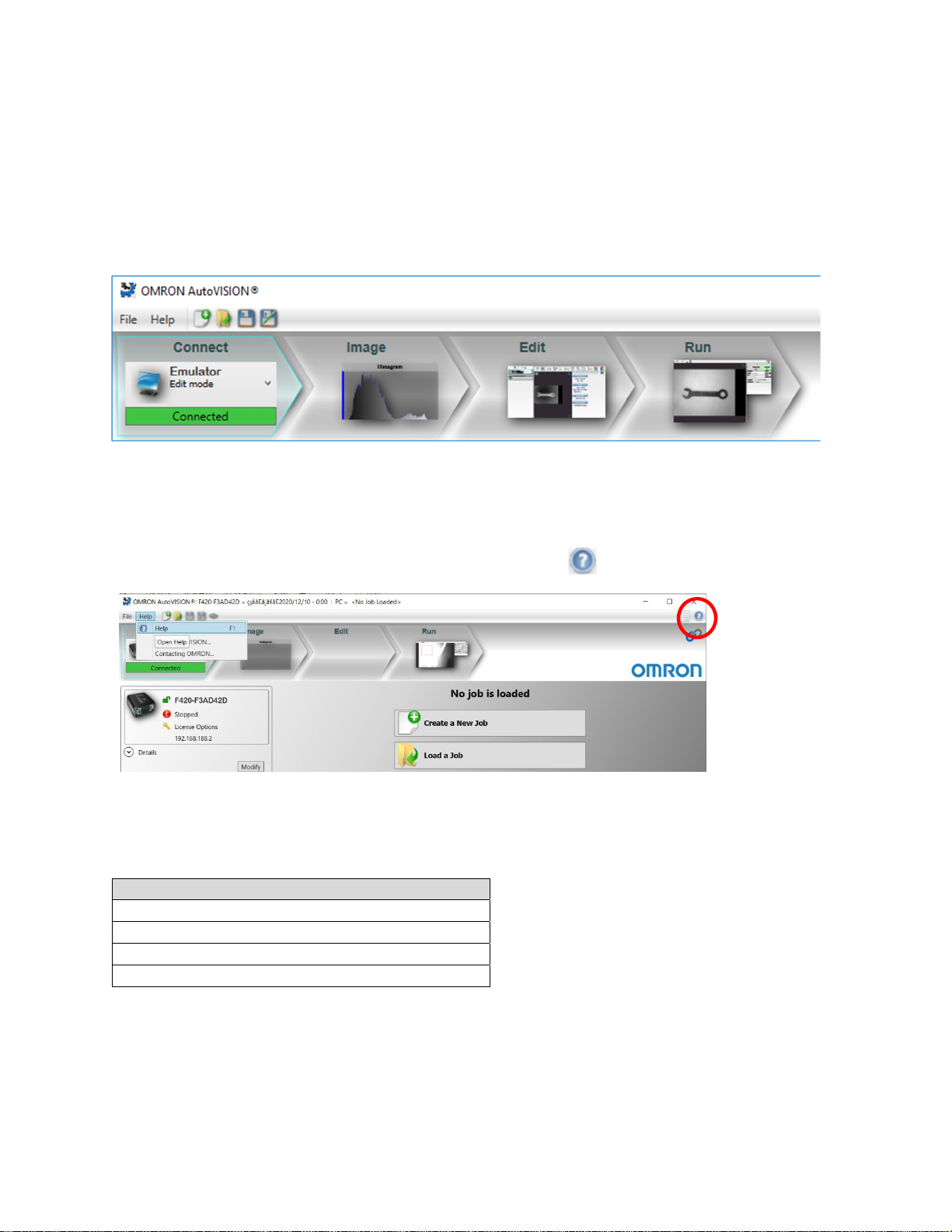
AutoVISION Help
Full details for the operation of AutoVISION can be found in Help. You can access the HELP from the UI
two ways, either through the menu or by clicking on the help icon .
Additional Material for the purchase, setup and operation of your Omron Vision System can be found on
your local Omron Website. These include:
Name of Manual
Camera specific Datasheets
Quickstart Guides
Camera specific Hardware User’s manual
Communication and Industrial protocol manual
Page 5

AutoVISION Quick Start Guide December 2020
The symbols used in this manual have the following meanings
Precautions for Correct Use
Precautions on what to do and what not to do to ensure proper operation and performance.
Additional Information
Additional information to read as required.
This information is provided to increase understanding or make operation easier.
Page 6

AutoVISION Quick Start Guide December 2020
1. Ins
Minimum PC Requirements
tall and Start Au
a. Download the latest version of AutoVISION software from the Omron website.
b. Double cli
(File name example:
c. Double cli
(*)
Intel® Core™
Internet
2GB RAM (Windows 7 SP1 / Windows 7 Embedded St
64GB hard
32-bit color display, 1366 x 768 or 1280 x 960
4.0 Windows Experience Index (particularly for graphi
1 USB 2
ck (run) the downloaded installer.
ck (run) the AutoVISION icon(*) on your desktop
Explorer 11 / Google Chrome
drive space
.0 port and 1 Netw
toVISION
SetupAutoVISION_522_3016.exe)
i3 Processor @1.6GHz
andard SP1)
cs)
ork port
Page 7
AutoVISION Quick Start Guide December 2020
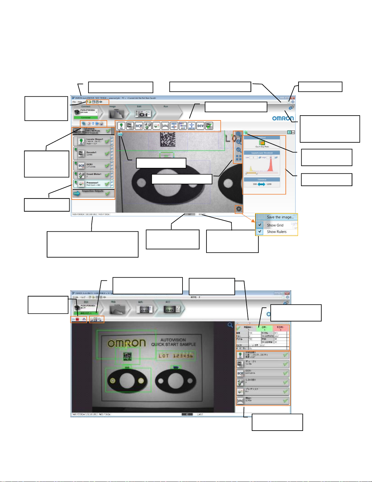
2. AutoVISION Display and basic operation
a. Edit mode
Job(setting data) name Advanced Parameters menu Help menu
Create new job
/Save job to PC・
Camera
Display option
/Delete selected
job/Tryout
Tool list view
・Camera mode:Camera MAC address/IP
address/camera model name
・Emulator mode:load image file name
b. Run
mode
Acquire Single image
Zoom options
Intensity on mouse
pointer (0~255)
Tools
Data navigator menu (Check
the detail in HELP)
Rotation option of ROI
(Region of Interest)
Tool parameters view
Pixel coordinate on
mouse pointer
(Unit:pixel)
Run/Stop/Trigger
button
Image Display Options/Image
Saving Options/Job Switching
Counter reset
button
Inspection Statistics
view
Result of each tool view
Page 8

AutoVISION Quick Start Guide December 2020
Basic operation
c.
ck
・
Left cli
:
Select
Drag with r
・
Upper scro
・
Lower scroll/Pinch i
・
ight click:Repositi
ll/Pinch out/Swipe down with 2 fingers/Double tap
on image
n/Swipe up with 2 fingers
Zoom out
:
Zoom in
:
Page 9
AutoVISION Quick Start Guide December 2020
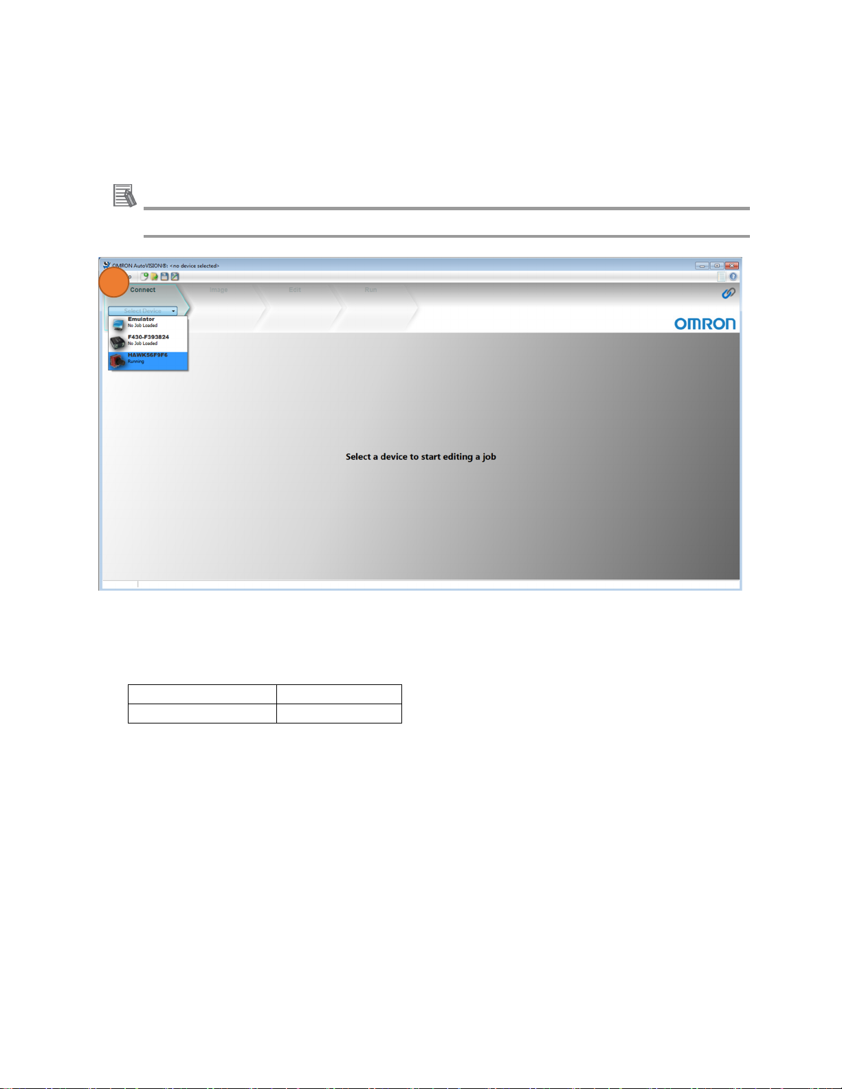
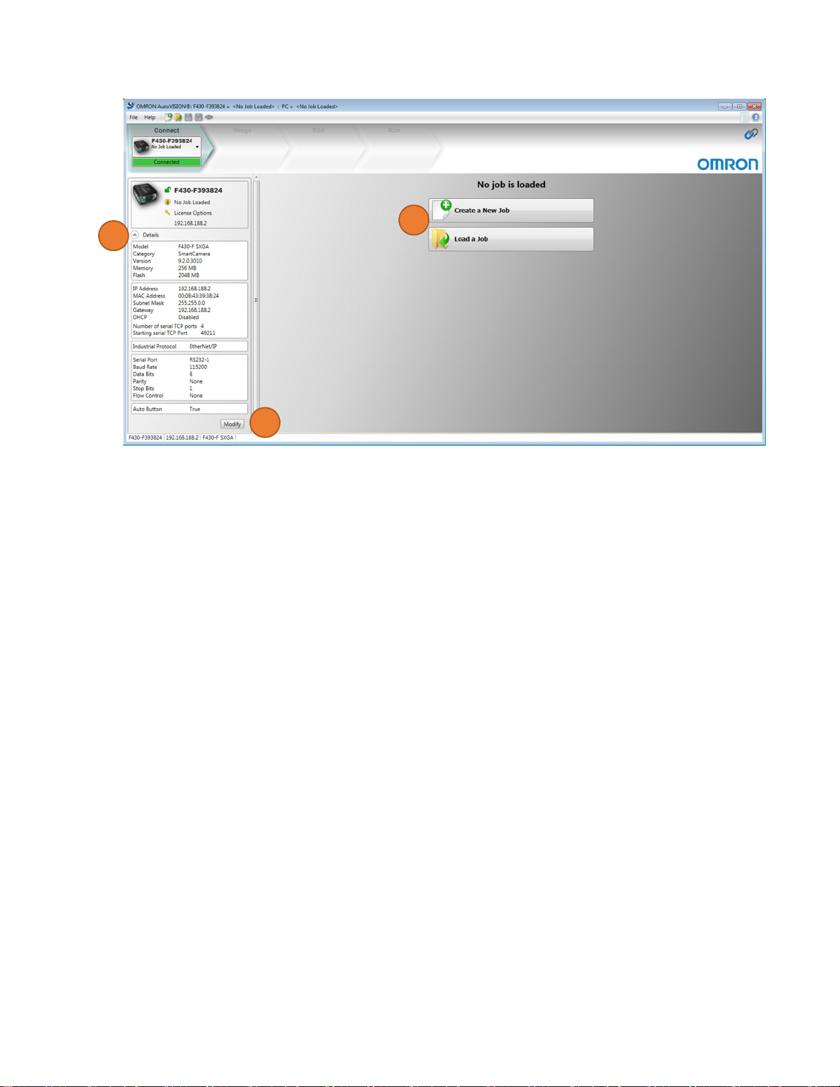
3. Connect to the Camera
Select the device to be used with AutoVISION.
a. Select the camera in the drop-down box.
Additional Information
Select [Emulator] if you want to verify by saved images
a
b. The F430-F camera is set by default as below. Set your computer to a compatible address or if the
network parameters need to be changed.
IP address 192.168.188.2
Subnet mask 255.255.0.0
i. Click [Details] button to see the IP Address
ii. Click [Modify] to make changes. This may request to reboot your camera. Modification is
reflected when reconnection is completed.
c. Select [Create a New Job].
Page 10
AutoVISION Quick Start Guide December 2020
c
bi
bii
Page 11
AutoVISION Quick Start Guide December 2020
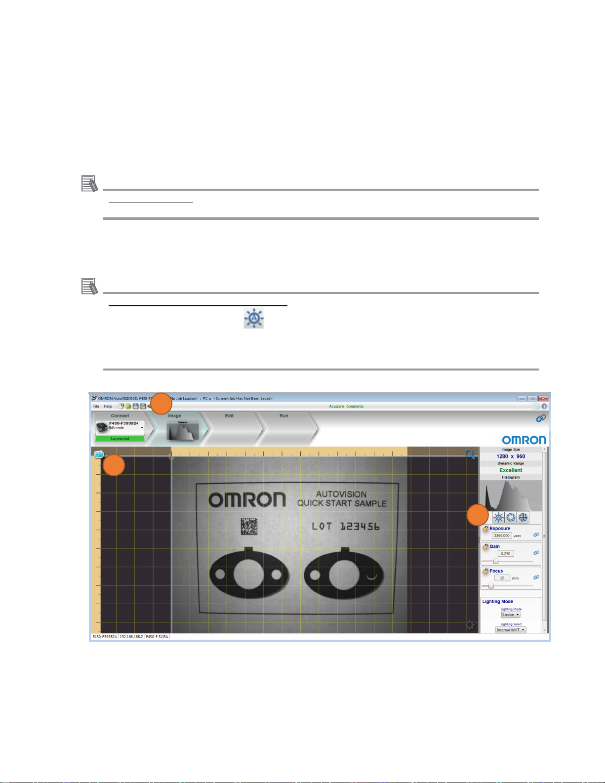
4. Capture an Image
Adjust the camera and lighting settings to produce the best image.
a. Select the Image view on Navigator bar to adjust your image for best performance. Creating a New
Job will move you automatically to Image view.
b. Capture images by clicking on the blue camera icon. If you have hardware connected, you will also
have live image icon.
Additional Information
Using the Emulator
p.10 describes how to load saved images into AutoVISION.
c. The camera and lighting settings are available on the right side. These settings include [Exposure],
[Gain], [Focus] and [Lighting] Modes.
Additional Information
About Exposure, Gain, Focus adjustment
Click the Auto Calibration icon for optimal camera parameters to be set automatically. This
feature works best if there are high contrast features in the center of the image. After Auto
Calibration has completed, click the blue camera icon to capture a new full screen image with
these settings.
a
b
c
Page 12
AutoVISION Quick Start Guide December 2020
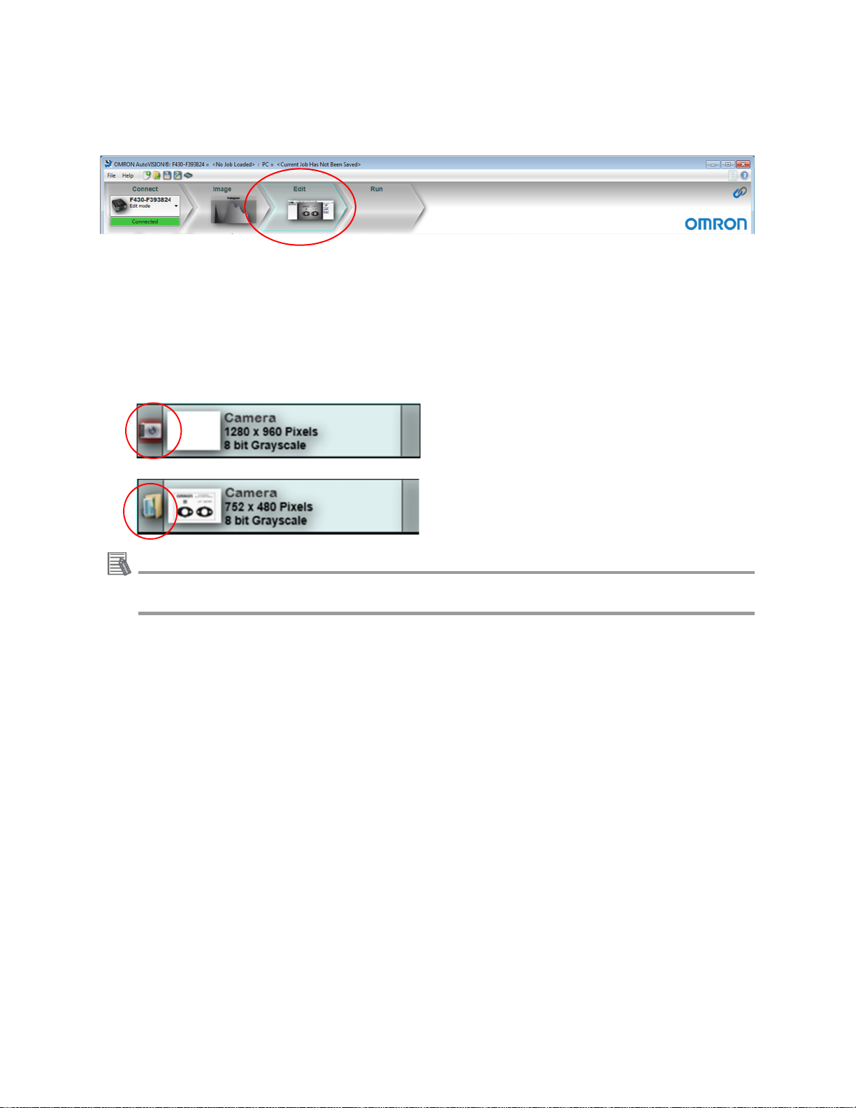
5. Edit Vision Job
Select the Edit view on Navigator bar to add or adjust the VISION Tools used in your job.
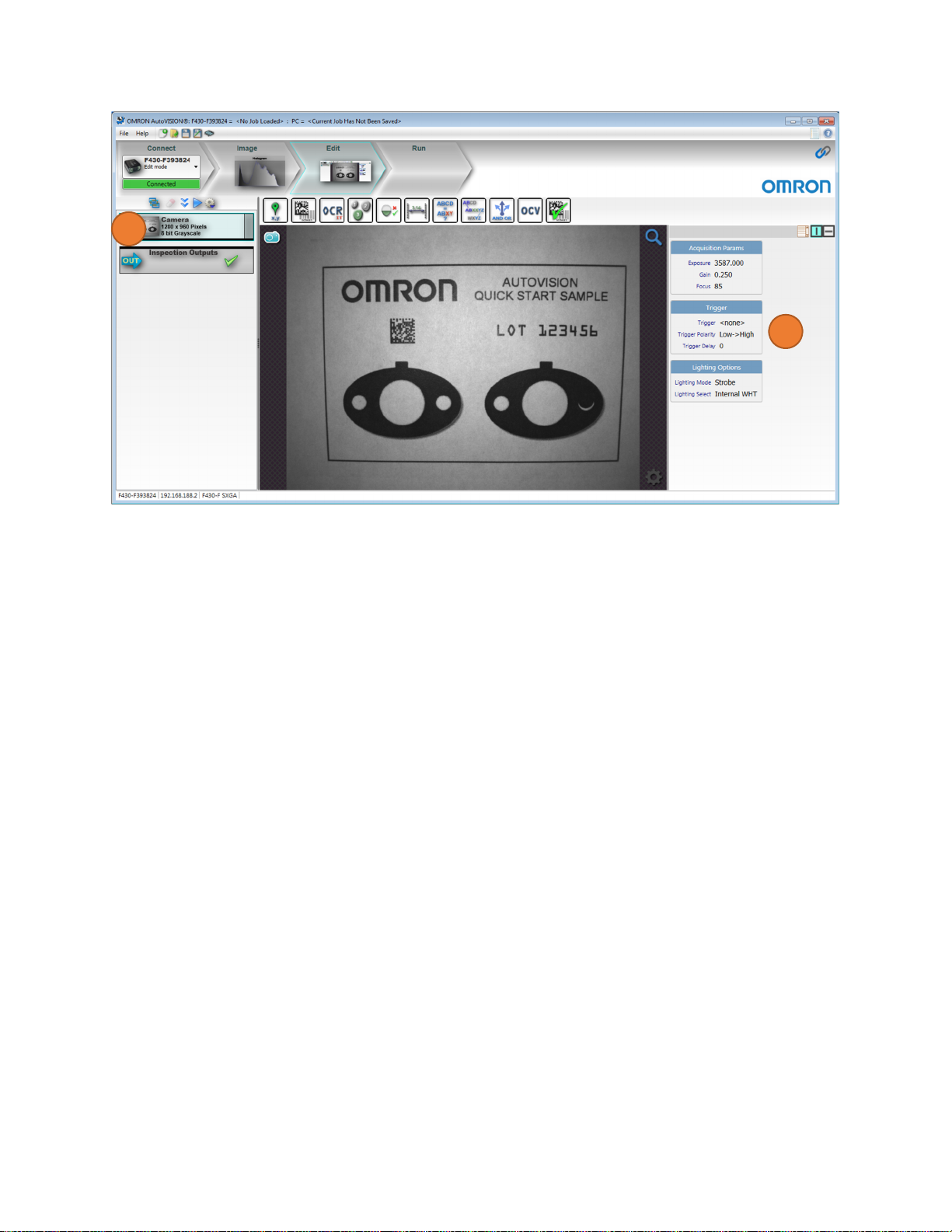
5.1 Set Camera Parameters
Adjust camera parameters, including the camera trigger. Load saved images if using an Emulator.
a. To the left of the image is the tool list with the Camera at the top. Select the Camera in the tool list.
The selected tool will turn light blue.
i. To use saved images, click the camera icon on the left side of the Camera tool. This will change
the icon to a folder and a dialog box will be displayed allowing your choose the folder that contains
the saved images.
ii. Clicking on the Folder will toggle back to taking images from the connected hardware.
Additional Information
The images for this AutoVISION quick tutorial are located at:
C:\Omron\AutoVision\TestImages\AV Quick Start
b. To the right of the image are the settings associated with the selected tool. Set the desired trigger
settings. In this example, leave this setting at [none] or [Virtual] for this job.
Page 13
AutoVISION Quick Start Guide December 2020
a
b
Page 14

AutoVISION Quick Start Guide December 2020
5.2. Use Locate tool
The Locate tool is used to detect a parts position and orientation. Locators can also be used compensate
for part movement and rotation by moving subsequent tools into place based on the found location
point.
In this example, set the tool up to locate “OMRON” logo position and rotation.
a. The available tools are shown in a toolbar just above the image. Click on the [Locate Tool] icon to
add this tool to the job.
b. This tool has two regions of interest (ROIs). The inner ROI (Template ROI) is the locate pattern
(“OMRON” log in this example) to learn. The outer ROI (Locate Shape ROI) is the search area for
this pattern. Adjust the regions as shown below.
a
b
c. Click the Red Train icon in the upper left of the Template ROI. After training the ROIs will
become green and a yellow outline should be seen around the learned pattern.
c
Page 15

AutoVISION Quick Start Guide December 2020
Precautions for Correct Use
Direction of adjust parameters
a.
To
reduce inspection time
t [Allowed Rotation] as small as
Adjus
Ex.) If
the work will not rotate, set from +\-180(Default) to 10 degree or less. Just enough fo
normal rotation.
possible
r
b.
To prevent fr
i. To preven
ii. To prevent from lack of detection: Set [Fit Quality] to [Relax
(*)[Accept Threshold]
[Show Advanced Parameters Window] and adjust other parameters. To check the detail, see
HELP.
om miss-dete
t from finding wrong parts: Set [Fit Quality] to [Precise]
and [Conformity Tolerance] are automatically set. If now solved, click
ction
ed] (*)
Page 16

AutoVISION Quick Start Guide December 2020
5.3. Use Decode Tool ,Enable Location and Rotation based on Locator
The Decode Tool is used for reading 1D/2D codes. In this example, read the Data Matrix symbol
Additional Information
To display only the selected tool’s ROI
You can see and control all the ROIs for multiple tools in default. Click [Show only the ROI of the
selected Tool] icon , then you can prevent from changing other ROI’s position. It is available
if the icon changes to .
a. Select the [Decode (bar
code) Tool] icon to add this tool to the job.
b. Resize the Decode tool ROI around the Data Matrix Symbol. This tool typically wo
default setti
ngs. No parameter changes are required in this exampl
a
b
e.
rks well with
Page 17

AutoVISION Quick Start Guide December 2020
c. Enable the [rotate option] in the Decode tool parameters. When enabled the icon will be lig
This will allow the tool to rotate based on the angle of the [Locate tool].
blue.
c
onal Information
Additi
ROI rotation option
The tool rotation can be adjusted by clicking on the blue round rotation handle seen on the
right side of the ROI and dragging to the desired rotation.
ht
Precautions for Correct Use
Direction of adjust parameters
a.
ROI
size
i. Make the Decode tool ROI 20 % larger than the 1D/2D code to allow for the quiet
To detect the
in bottom part of AutoVISI
code size, mouse over to code symbol and check the pixel coordinate shown
ON.
zone.
Page 18

AutoVISION Quick Start Guide December 2020
ii. If the 2D code is rectangular, enble both DataMatrix ECC200, and
the bottom of the code selection list. DRME is for rectangular codes and will enhance the
systems ability to find them.
b.
When faced with other diffiult to read applications, try to use [Custom features]. You can
use this in [Shown the Advanced Parametes Window]. See HELP for more detail.
DataMatrix DMRE at
Page 19

AutoVISION Quick Start Guide December 2020
5.4. Use OCR Tool
This tool is used to read expiration date and LOT numbers etc. Read “LOT 123456” string in this example.
a. Select the [OCR Tool] icon to add this tool to the job.
b. Resize the OCR tool ROI around the text, “LOT 12345
c. Enable
rotation for this
tool.
a
6”.
c
b
Page 20

AutoVISION Quick Start Guide December 2020
Precautions for Correct Use
Direction of parameter adjustment
To read correctly, click on character selection on the right side of the screen. The OCR algorithm
works in 2 steps: Segment characters→Recognize characters. Some keys for success are
described below. To check the detail for each parameter, see HELP.
a. Segment char
i. Adjust
ii. Set [Scaling factor] as “Character width” x “Scaling factor” = 30 pixel.
b.
Recognize characters
Adjust Confidence
same chara
the
correct character in the face of more variation
You can increase the recognition rate by adding
the
Font Library. Click on the character which should be added to library. The “A
sample” popset.
The rea
hovering ove
The
colors are defined as below in relationship to match score:
-Green:
acters
min/max character size according to actual size in AutoVISION image view
To detect the characeter size, mouse over to
coordinate sh
cter has different shapes. Even at 50% it will not tend to misread, but will
up will appear. Type in correct character and it will be added to the sample
d confidence for each character can also be seen as a value of 0 to
r a character and has a color associated with the read confid
81 – 100%
own in bottom part of AutoVISION.
below 0.8 (80%) to increase read rate. It is not uncommon
characters and
characters which are miss-classified into
.
check the pixel
that the
read
dd
1 when
ence.
-Orange: 51 – 80%
-Red: 0
– 50%
Page 21

AutoVISION Quick Start Guide December 2020
5.5. Use Count Tool
This tool detects the number of objects based on color or shape information. In this example, verify that
two small holes are in the gasket.
a. Select the [Count Tool] icon to add this tool to the jo
b. Resize
c. Change
the Count Blobs tool ROI around the left gasket. Enable rotation for this t
the Blob settings to find the desired objects. Each blob will have a yellow perimeter with a
b.
crosshair ( + ) in the center. In the parameter settings on right side of screen:
i. Set [Polarity] to [Light on Da
ii. Adjust [
iii. Change
passes if it fi
Additi
Min and Max blob size] to count the two smaller white circles on each ga
the max and min range of the [Tolerance] to 2 <–> 2 to make sure the
nds the correct number of holes, which is 2 in this
onal Information
rk]
To detect optimal maximum/minimum blob size
This tool does not provide you the number of pixels of each blob. You will easily detect the size
of each blob by using [Presence/Absence tool] stated in next section. You can also change the
Min and Max size to determine empirically the correct value.
a
ool.
sket.
tool only
case.
b
c
b
Page 22

AutoVISION Quick Start Guide December 2020
5.6. Use Presence/Absence Tool
Use Zoom options
This tool detects the presence of a feature based on pixel intensity or contrast. Verify that the tab is
present in the gasket in this example.
a. Select the [Presence Tool] icon to add this tool to the job. Enable rotation for this tool.
a
biv
b. Use the Zoom button to make it easier to position the tool
i. Move the mouse over the [Zoom] icon
ii. Click [Zoom
iii. Righ
t click and drag to reposition image
in
(+)]
to see the Zoom options
iv. Resize and position the ROI over the left gasket tab
bi
Page 23

AutoVISION Quick Start Guide December 2020
c. Change the Presence tool settings to pass when the gasket tab is present in the tool. The orange
pixels inside the tool are the pixels that are counted.
i.
Adjust the Upper/Lower Threshold, using the sliders, to make the gasket tab appear
orange.
ii.
Set the [Tolerance] so that the Presence tool will pass when a gasket tab is in the tool
but fails when the tool contains all light or dark pixels. Note the pixel count in the
[Presence1] tool on the left side of the screen. The lower and upper tolerance settings
should bracket this value to determine if the tab is present.
iii.
Enable the Rotate option.
d. Click [Zoom to Fit] to see the entire image
ciii
d
ci
cii
Page 24

AutoVISION Quick Start Guide December 2020
5.7. Use Measure Tool
This tool allows you to perform width or height measurements between two edges or circle radius etc.
Measure the width of the gasket tab in this example.
a. Select the [Measure Tool] icon to add this tool to the job. Width measure is default.
b. Resize and position the ROI over the right gasket tab. Zoom in if desired. Enable rotation in this tool.
c. Change the Measure tool settings to pass when the gasket tab is the correct width.
i.
Adjust the [Edge Strength] to find the desired edge.
ii.
Adjust the [Tolerance] so that the tab only passes when it is the correct width. The current
width is shown in [Measure1] in the tool list on left side of screen.
a
a
b
d. The [Measure tool] also has a calibration options. The first is Simple Calibrate You can convert
the measurement result from pixel to required unit. To use this feature:
i.
Click [Calibrate]
ii.
The current measurement in pixels is displayed in the [Measured Value] field (Default:
pixel to ich conversion value)
iii.
iv.
In the [Real World Value] field enter the current measurement
Enter the measurement units (Ex. In. to mm)
v.
Click [Calibrate]
e. AutoVISION also allows full non-linear calibration based on inputting data from a target. Use the
Omron Device Non-linear Calibration Utility in the start menu. This will create a calibration file
that you can load into your job through the AutoVISION File menu.
ci
Page 25

AutoVISION Quick Start Guide December 2020
d
Page 26

AutoVISION Quick Start Guide December 2020
5.8. Try All Tools
Try all the vision tools in the job to confirm that they are configured as desired.
a. [Tryout Once] button will capture a new image and run all tools, once on the PC. Look at status
indicators. A green check means the tool has passed. A red X means the tool has failed, for
reason such as wrong count, or out of tolerance.
b. Tryout Loop button will capture a new image and run all tools. Once completed it will repeat
this process continuously until the Stop Loop button is pressed.
Additional Information
In case of using Emulator mode
a.
Tryout the
b.
The available
TIFF/BMP/PNG image of same resolution
images in selected folder one by one.
image are the one acquired by MicroHawk smart camera series or
.
a
b
Page 27

AutoVISION Quick Start Guide December 2020
5.9. Set Inspection Outputs
This tool communicates inspection results to another device. Basic means are [Digital output] and
[TCP/IP and Serial Output String]. In addition, you can use some MSLink and industrial protocols. In this
example, see how to use [Digital output] and [TCP/IP and Serial Output String].
5.9.1. Digital Outputs
Digital Outputs are a fast, easy method of indicating the inspection results to another device, like a PLC
or stack light.
a. Select the [Inspection Outputs] in the
b. Click
the [Digital Output
a
s]
tool list
b
c. Assign th
under Output 1/2/3 and select Inspection Done. Set the desired pulse width time, in
Click
make i
t 20 ms (milliseconds
e outputs in the Digital Outputs pop up wind
).
ow.
this job
Page 28

AutoVISION Quick Start Guide December 2020
c
Page 29

AutoVISION Quick Start Guide December 2020
5.9.2.TCP/IP and Serial Output String
TCP/IP or Serial output messages provide the ability to transmit inspection results like a barcode or
measurement to another device. In this example we will send the Decode1 tool string followed by CR LF
(Carriage Return + Line Feed) characters.
a. Select TCP/IP and Serial Ou
b. Select String
c. In t
he TCP/IP and Serial Out window we need to build the output string. Select the blue + sy
and sel
Output Port and choose TC
ect Tool Output Value. This will add a field to the Build Output String region that states
[Not Connected].
d. Select the blue + sy
to the
output string.
mbol
t
a
P1 (49211).
mbol
and select Text. This will enter a field to allow you to add characters
e. Click on
b
c
the [Not Connected] field, under [Decode1], select [Decoded
Text].
Page 30

AutoVISION Quick Start Guide December 2020
e
f. Click in the blank text field and enter: \r\n
f
g. The results can be seen in a telnet client window when an inspection is completed in Edit mode using
the [Try Once] or [Try Loop] buttons and in Run mode.
Page 31

AutoVISION Quick Start Guide December 2020
5.9.3. Opening Telnet Client to view results
Additional Information
Reason to test using Telnet Client
Quickly see the results that are output from your camera over a specific TCP/IP Socket and Port.
If the Telnet Client has not been enabled in Windows, please go to the link below and follow the
instructions to enable this Windows feature.
https://social.technet.microsoft.com/wiki/contents/articles/38433.windows-10-enabling-telnetclient.aspx
a. Click the Windows Start button, type cmd.exe and hit the Enter key.
b. In the cmd.exe window type the following command listed. Replace the 192.168.188.2 (Default
setting) with your camera IP address.
Precautions for Correct Use
Using Emulator
Your camera IP address can be found if you click on the word Connect in AutoVISION. If using
the Emulator use IP address: 127.0.0.1 (Loop back address).
Typical Example: Type telnet 192.168.188.2 49211
b
c. Click the [Try Once] button in AutoVISION. Each time the Inspection is run the decoded text is
shown in the Telnet window on a new line.
c
Page 32
AutoVISION Quick Start Guide December 2020
6. Save Job
Go to the [File] menu > [Save or click the Save] icon
Additional Information
About the [File] menu > [Archive Job] function
This will save the AutoVISION job and will make an additional Archive file that has an .AVZ
extension. The Archive file contains the AutoVISION job and all the additional support files (ex.
Font Library for the OCR Tool, Images, Locators, etc.) used by that job.
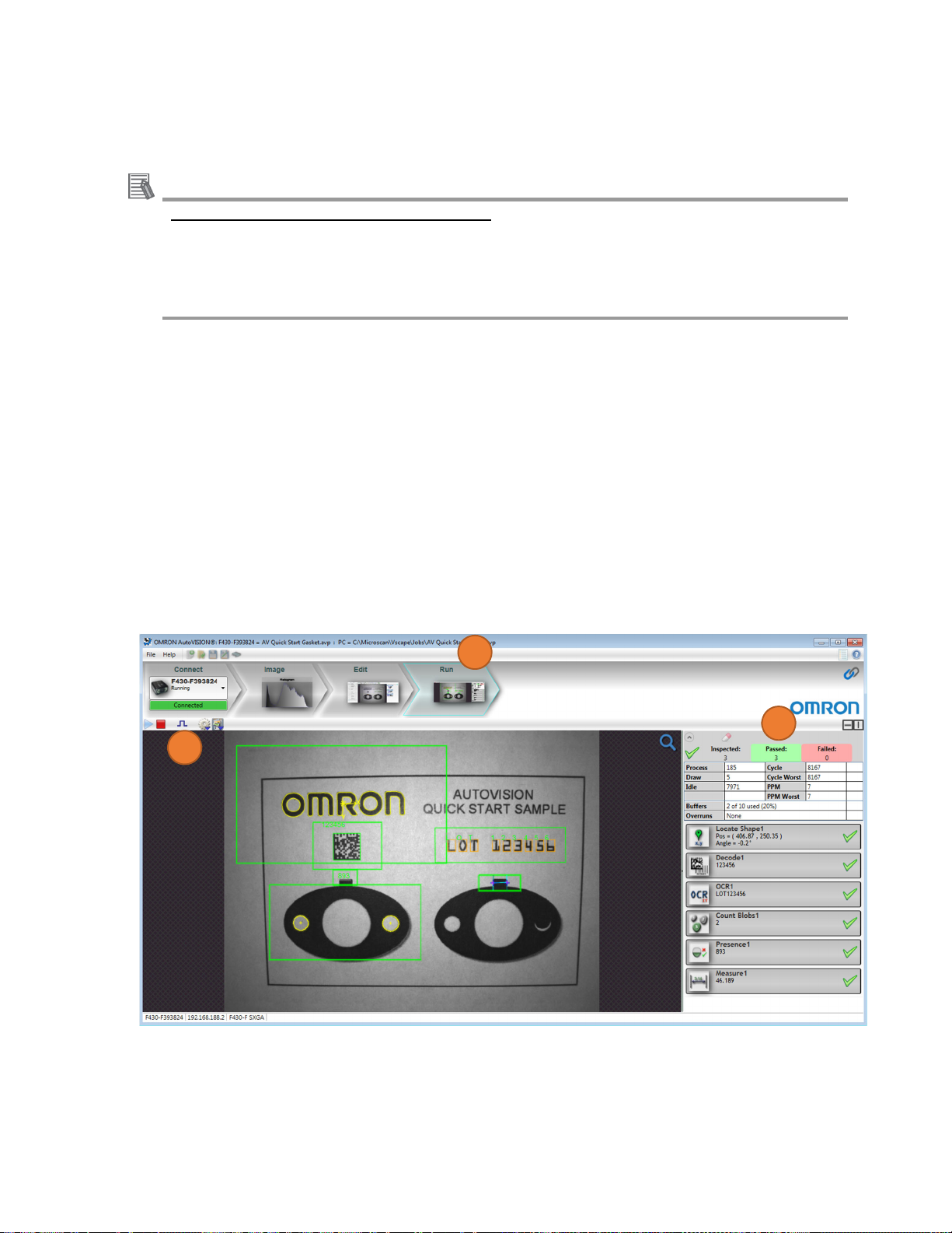
7. Run the Job
Download the job to the selected camera and run.
a. Select the [Run] view in Navigator bar.
The job is downloaded to the selected camera; once completed, the counters and tools are seen to
the right of the image area.
b. Counters and Tool results field. See HELP for details.
c. Trigger button
i.
If the trigger was set to none, the inspection will start running continuously.
ii.
If the camera was set to use a virtual trigger, click the Trigger icon to provide a trigger to the
camera.
a
cii
b
Page 33

AutoVISION Quick Start Guide December 2020
8. Saving setup or runtime images
a. Click [Image Saving Options] .
b. Click [Select Folder] and find the folder you would like to save images.
c. Select [Save as TIFF] or [Save as BMP].
d. Select the condition of saving images from: [Save All Images] [Save Failed Images] [Save Passed
Images].
e. Click [Run Job].
e
a
b
c
d
Page 34

AutoVISION Quick Start Guide December 2020
9. Save Job to flash memory on camera
Saving the job to flash memory on the camera is required to allow the camera to load and restart the job
on power up.
a. Select the [Edit] view in navigator bar.
b. Confirm that the job is correct and has been saved to the PC.
Additional Information
About file save type
It is recommended that you select File > Archive Job… This will save the job to the PC and
create an Archive file (*.avz) that contains the job and additional support files used by the job.
c. Select the camera flash memory icon
d. Select the memory slot to write
i.
Select [New Slot] to write this job to the camera.
ii.
If jobs exist on the camera, selecting an existing slot will overwrite that memory slot.
c
d
e. A pop-up window may appear which will allow you to overload the desired job to the camera.
e
Page 35

AutoVISION Quick Start Guide December 2020
10. Switch Job which is saved in camera
a. Select [Connect] view in navigator bar
b. Below the
[Load a Job] button is a listing of the jobs stored in flash memory on the ca
c. If multiple jobs are stored
camera powe
r up, and click [Make Current].
in flash memory, select the desired job slot that should be loaded
mera.
on
Additional Information
About management of job size
Click [Refresh the job list] , then you can see the list of file size for each job and free memory
size.
11. Edit job which is saved in camera
Select the job to be edit, click [Upload Current Job from
Device]
Click [Load a Job] and select target *avp/*avz file.
10.a
12
11
10.b
10.c
Refresh the job list
Page 36

AutoVISION Quick Start Guide December 2020
Appendix A – Quick Start Samples
The AutoVISION quick start images used in this document are located at:
C:\Omron\AutoVision\TestImages\AV Quick Start
There are another sample images and jobs in below folder. Use them for your reference located at:
C:\OMRON\AutoVision\TestImages
Good Sample
Bad Sample
Page 37

AutoVISION Quick Start Guide December 2020
Appendix B – Use Omron Microscan Link
AutoVISION allows you to link tool parameters to tags within the software's Global Data Service GDS .
This makes it possible to "set and get" the parameter values via any GDS-supported protocol, including
serial, TCP/IP, EtherNet/IP, and PROFINET I/O. Example of count tool setting is below. See HELP for
more detail.
a. Set up [Count tool].
b. Click the link button in [Count tool] in tool list.
c. Hovering the mouse over the link buttons identifies their associated parameter as shown below.
Clicking the link button displays the Link Menu populated with GDS tags of a compatible type.
d. Select the variable to be linked.
e. Once a parameter is linked, the background of the link button turns green.
f. There are other parameters to be linked which is not shown in tool list. To check all, click [Data
nacigator] . To check each parameter, see HELP.
Page 38

AutoVISION Quick Start Guide December 2020
Additional Information
Memory map of MicroHawk smart camera
The memory map for each type of variable is pre-defined as below. To check details, see
industrial protocol manual (*).
(*)C:\OMRON\Vscape\Documentation\industrialprotocolmanual.en.pdf
Ex.)Input assembly layout of Ethernet/IP
Page 39

AutoVISION Quick Start Guide December 2020
Appendix C – Use FTP Image Output
To save images to server via PLC, you can use FTP protocol by below step.
a. Click [Edit] in Navigator bar and click [Inspection Output] in left tool list.
b. Click [FTP Image Output] in right image view.
c. Fill each parameters of FTP server and other options.
Precautions for Correct Use
About File name format
There is a different in file name format between using AutoVISION soft trigger and PLC
command trigger.
Trigger from AutoVISION:”Characters set in Job”+yy-mm-dd-….tif
Trigger from PLC
Precautions for Correct Use
Specification of TimeStamp
There is a different in file name format between using AutoVISION soft trigger and PLC
command trigger.
TimeStamp is the time count[us] after booting.
Additional Information
How to change file name
You can change base file name from PLC by using Omron MicroScan Link Tag (stringN)
:
”Characters set in Job”+TimeStamp.tif
Ex). If the goal format is “ABC000-01_TIMESTAMP.tif”, the serial command is “SET stringN
ABC000-01”
Page 40

AutoVISION Quick Start Guide December 2020
Appendix D – Correlation table with Omron FH/FQ series
The definition of specific words is different between MicroHawk smart camera and Omron FH/FQ. This
section introduces the customer who is familiar with Omron FH/FQ series to understand the meanings
easier by showing the list of each word. Note that these are the explanation of similar functions. No
compatibility for them.
MicroHawk smart camera main
functions
Locate(Locate Shape mode)
Decode Barcode/2D code Can I change the match strings from external
OCR OCR
Count Labeling Can I check the number of pixel for each Blob?
Presence/Absence Gravity Can I output gravity coordinate?
Measure Edge Position/Scan Edge
Omron FH/FQ similar functions MicroHawk smart camera’s FAQ
Shape Search III Can I add or delete some of model edges to get
more stable result?
No
→
device?
Yes. Use OmronMicroScanLink.
→
No. But you can check Min/Max number of
→
Blobs in data navigator.
No. Use [Locate tool] and select [Locate Blob]
→
mode.
Can I calibrate using calibration plate?
Position/Circular Edge Position
Yes. See [Multi Dot Calibration Utility] in
→
HELP.。
Image Preprocessing Filtering Can I use multiple preprocessing unit?
No
→
Save Image Image logging Can I select any folders to save images (Ex. USB
folder)?
Yes
→
Job Scene How many jobs can I save in camera?
Until you use all the free memory.
→
Calibration(Exposure/Gain/Focus)
Calibration(Pixel→mm)
None
Same as left
Page 41

Authorized Distributor:
1220 (0520)
© OMRON Corporation 2020 All Rights Reserved.
In the interest of product improvement, specifications
are subject to change without notice.
Z434-E-02 (84-9100005-02)
OMRON Corporation Industrial Automation Company
OMRON ELECTRONICS LLC
2895 Greenspoint Parkway, Suite 200
Hoffman Estates, IL 60169 U.S.A.
Tel: (1) 847-843-7900/Fax: (1) 847-843-7787
Regional Headquarters
OMRON EUROPE B.V.
Wegalaan 67-69, 2132 JD Hoofddorp
The Netherlands
Tel: (31)2356-81-300/Fax: (31)2356-81-388
Contact: www.ia.omron.com
Kyoto, JAPAN
OMRON ASIA PACIFIC PTE. LTD.
No. 438A Alexandra Road # 05-05/08 (Lobby 2),
Alexandra T echnopark,
Singapore 119967
Tel: (65) 6835-3011/Fax: (65) 6835-2711
OMRON (CHINA) CO., LTD.
Room 2211, Bank of China Tower,
200 Yin Cheng Zhong Road,
PuDong New Area, Shanghai, 200120, China
Tel: (86) 21-5037-2222/Fax: (86) 21-5037-2200
 Loading...