

Page 1
Z/A/X/DZ Common Accessories Z/A/X/DZ F-189
Limit
Switches
Z/A/X/DZ Common Accessories
Z/A/X/DZ
Ordering Information
■ List of Models
Terminal Covers (Sold Separately)
Common to Z, A, X, and DZ Models
The Terminal Cover is secured with mounting screws and protects the casing and terminal wires from dust, vibration, or fingers, thus preventing
terminal short-circuiting, ground faults, wire disconnection or improper connection, and electric shock accidents.
Terminal Covers made of phenol resin have five or six thin wall sections. These sections can be torn open for providing holes for lead cables at
desired points.
Note: Use the screw-terminal use Terminal Cover for DZ-series soldering-terminal models.
Separator (Sold Separately)
Common to Z, A, X, and DZ Models
Model: Separator for Z
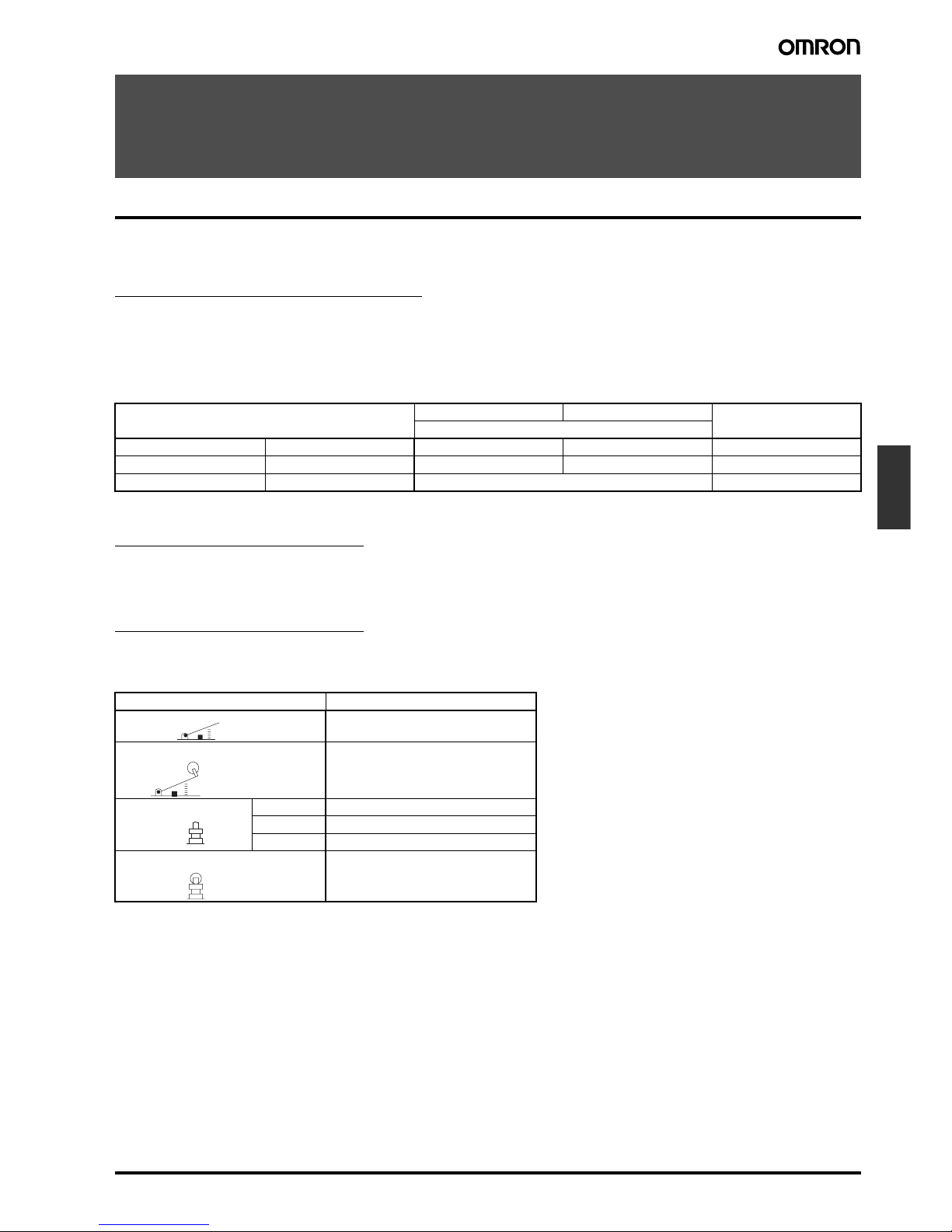
Actuators (Sold Separately)
Common to Z and X Models
A Switch can be actuated by a cam or an appropriate object, in which case, use one of the following Actuators according to the application.
Application Soldering terminal use Screw terminal use Remarks
Material Mounting direction Model
Phenol resin Side mounting AP-A AP-B --Metal press mold Side mounting AP1-A AP1-B Used for AP-A and AP-B
Vinyl chloride Side mounting AP-Z ---
Actuator Common to Z and X models
XAA-1
ZAA-2
Short ZAQ-3
Medium ZAQ-2
Long ZAQ-1
ZAQ-22
Hinge lever
Hinge roller lever
Panel mount plunger
Panel mount roller plunger
Page 2
F-190 Z/A/X/DZ Common Accessories Z/A/X/DZ
Dimensions
■ Dimensions and Operating Characteristics
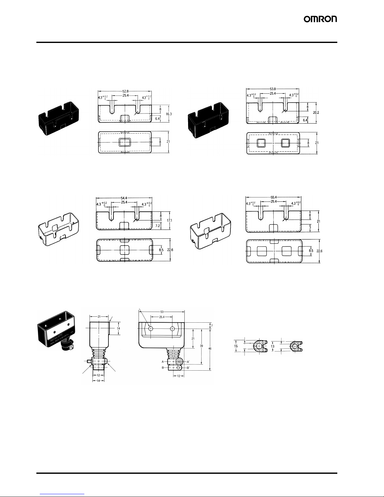
Terminal Covers
Note: Each dimension has a tolerance of ±0.4 mm unless otherwise specified. (±0.8 mm for the AP-Z)
2.15R
2.15R
2.15R
2.15R
AP-A AP-B
AP1-A AP1-B
Soldering Terminal Use
(Phenol Resin)
Note: The Cover has five thin, easy-to-separate por-
tions for easy lead wire connections.
Screw Terminal Use
(Phenol Resin)
Note: The Cover has six thin, easy-to-separate por-
tions for easy lead wire connections.
Soldering Terminal Use
(Metal Press Mold)
2. AP1-A should be used with AP-A.
Note: 1. The Cover has five holes for easy
lead wire connections.
Screw Terminal Use
(Metal Press Mold)
2. AP1-B should be used with AP-B.
Note: 1. The Cover has six holes for easy
lead wire connections.
AP-Z
Nut
Cable Pull-out Dimension
A-A' cross-section B-B' cross-section
Two, 4.2 dia.
8 dia. 6 dia.
Soldering or Screw Terminal Use
(Vinyl Chloride)
Pressure plate
(t1 steel)
M3 × 20 Phillips screw
(with plane washer and
nut)
Note: A 6-dia. or 8-dia. cable can be used by
cutting the cable pull-out hole to the size
of the cable to be used.
Page 3

Z/A/X/DZ Common Accessories Z/A/X/DZ F-191
Limit
Switches
Separator
Actuators
Note: These Actuators are not provided with Switches.
Note: Each dimension has a tolerance of ±0.4 mm unless otherwise specified.
t = 0.34
Two, 4.5 dia.
Note: 1. Each dimension has a tolerance of +0.4 mm unless
otherwise specified.
2. The material is EAVTC (Epoxide Alkyd Varnished
Tetron Cloth) and its heat-resisting temperature is
130°C.
Model Z-15G-B X-10G-B
OF max.
RF min.
PT max.
OT min.
MD max.
4.90 n {500 gf}
1.67 N {170 gf}
6 mm
12.7 mm
2.2 mm
4.90 n {500 gf}
1.67 N {170 gf}
6 mm
12.7 mm
3.3 mm
FP max. 32.9±1.6 mm
Model Z-15G-B X-10G-B
OF max.
RF min.
PT max.
OT min.
MD max.
4.90 n {500 gf}
1.67 N {170 gf}
6 mm
12.7 mm
2.2 mm
4.90 n {500 gf}
1.67 N {170 gf}
6 mm
12.7 mm
3.3 mm
FP max. 44.5±1.6 mm
60R
Hinge Lever
XAA-1
Two, M4
Two, M4 30
Stainless steel
58.5R
Hinge Roller Lever
ZAA-2
Two, M4
Two, M4 30
Stainless steel
9.5 dia. × 4.8 (stainless-
steel roller)
Page 4

F-192 Z/A/X/DZ Common Accessories Z/A/X/DZ
Note: 1. Stainless-steel pin plunger
2. Bronze frame
3. Incomplete screw section part
with a maximum of 1.5 mm
Note: This Actuator (pin plunger) can be used with Standard Pin Plungers (Z-15G(-B), Z-15E(-B), X-10G(-B), DZ-10G-1A(-1B)) for the Z, X, and
DZ models.
Note: 1. Stainless-steel pin plunger
2. Bronze frame
3. Incomplete screw section part
with a maximum of 1.5 mm
Note: This Actuator (pin plunger) can be used with Standard Pin Plungers (Z-15G(-B), Z-15E(-B), X-10G(-B), DZ-10G-1A(-1B)) for the Z, X, and
DZ models.
Note: 1. Stainless-steel pin plunger
2. Bronze frame
3. Incomplete screw section part
with a maximum of 1.5 mm
Note: This Actuator (pin plunger) can be used with Standard Pin Plungers (Z-15G(-B), Z-15E(-B), X-10G(-B), DZ-10G-1A(-1B)) for the Z, X, and
DZ models.
Model ZAQ-3
Z-15E-B X-10G-B
OF max.
RF min.
PT max.
OT min.
MD max.
8.34 N
{850 gf}
1.12 N
{114 gf}
0.8 mm
4.8 mm
0.15 mm
5.39 N
{550 gf}
1.12 N
{114 gf}
1 mm
4.5 mm
0.2 mm
OP 27.8±1.5 mm
23.3
Short Panel Mount Plunger
ZAQ-3
Two M4 nuts
7.9 dia.
(Note 2)
(Note 3)
12SR
(Note 1)
14.5
dia.
2 t × 15.6 width
across flats
2 t × 14 width across
flats
M12 × 1 mounting
screw
Two M4 × 25 ± round
head screw
Model ZAQ-2
Z-15E-B X-10G-B
OF max.
RF min.
PT max.
OT min.
MD max.
8.34 N
{850 gf}
1.12 N
{114 gf}
0.8 mm
4.8 mm
0.15 mm
5.39 N
{550 gf}
1.12 N
{114 gf}
1 mm
4.5 mm
0.2 mm
OP 53.2±1.5 mm
23.3
Medium Panel Mount Plunger
ZAQ-2
7.9 dia.
(Note 2)
(Note 3)
Two M4 nuts
12SR
(Note 1)
14.5
dia.
M12 × 1 mounting
screw
2 t × 14 width across
flats
2 t × 15.6 width
across flats
Two M4 × 25
screw
Model ZAQ-1
Z-15E-B X-10G-B
OF max.
RF min.
PT max.
OT min.
MD max.
8.34 N
{850 gf}
1.12 N
{114 gf}
0.8 mm
20.6 mm
0.15 mm
5.39 N
{550 gf}
1.12 N
{114 gf}
1 mm
20.4 mm
0.2 mm
OP 69.1±1.5 mm
23.3
Long Panel Mount Plunger
ZAQ-1
7.9 dia.
(Note 2)
(Note 3)
Two , M 4 × 25 screws
Two, M4 nuts
12SR
(Note 1)
14.5
dia.
M12 × 1 mounting
screw
2 t × 14 width across
flats
2 t × 15.6 width
across flats
Page 5

Z/A/X/DZ Common Accessories Z/A/X/DZ F-193
Limit
Switches
Note: This actuator (roller plunger) can be
used with standard pin plungers (Z-
15G(-B), Z-15E(-B), and DZ-10G-
1A(-1B)).
It cannot be used with X models.
Model ZAQ-22
Z-15E-B X-10G-B
OF max.
RF min.
PT max.
OT min.
MD max.
8.34 N
{850 gf}
1.12 N
{114 gf}
0.8 mm
20.6 mm
0.15 mm
5.39 N
{550 gf}
1.12 N
{114 gf}
1 mm
20.4 mm
0.2 mm
OP 37±0.8 mm
48
OP
PT
20.7
1.6
23.3±
0.25
23.9
4.8
20.7
11.9
49.2
25.4±
0.2
18.9
Panel Mount Roller Plunger
ZAQ-22
12.7 dia. (Note 1)
(Note 2)
(Note 3)
14.5
dia.
M12 × 1 mounting
screw
Spring washer
Note: 1. Stainless-steel pin plunger
2. Bronze frame
3. Incomplete screw section part
with a maximum of 1.5 mm.
Two , M 4 × 25
screws
Two hex nuts
5-mm thickness, 19 mm
between opposing edges
With groove for roller
penetration
Page 6

F-194 Z/A/X/DZ Common Accessories Z/A/X/DZ
In the interest of product improvement, specifications are subject to change without notice.
ALL DIMENSIONS SHOWN ARE IN MILLIMETERS.
To convert millimeters into inches, multiply by 0.03937. To convert grams into ounces, multiply by 0.03527.
Cat. No. B106-E1-01
 Loading...