

Page 1
Connections to a Wider Range of Slaves Ensured by Upgraded Models
ade U e
Slave
Products
from other
companies
New product
Products to be released soon
Note: 1. In
SMC
CKD
Koganei V
high-speed communications mode, the maximum transmission distance is
communications
2. The SR
T2-AD04 and SR
Master Conventional
SR
T1 Series
FND-Xj-SRT
Solenoid valve
for SI manifold
use
Solenoid valve
for saving wiring
effort
alve for saving
wiring ef
fort
mode (i.e., a newly available mode), the maximum transmission distance is 500 m at a baud rate of 93.75 kbps.
T2-DA02 are available for 16-bit synchronous communications.
VQ Series
SX Series
SY Series
4TB1 and 4TB2 Series
4TB3 and 4TB4 Series
4G Series
MN4SO Series
YS1A1, A2
YS2A1, A2
SRT2-AD02
SRT2-DA02
SRT2-VID08S(-1)
SRT2-VOD08S(-1)
SRT2-VID16ML(-1)
SRT2-VOD16ML(-1)
SRT2-ID16(-1)
SRT2-OD16(-1)
SRT2-ID08(-1)
SRT2-OD08(-1)
SRT2-ROC16
SRT2-ROF16
CPM1A-SRT21 Yes Yes Yes
SRT2-ID04(-1)
SRT2-OD04(-1)
SRT2-ID16T(-1)
SRT2-OD16T(-1)
SRT2-MD16T(-1)
SRT2-ROC08
SRT2-ROF08
models
C200HW-SRM21
CQM1-SRM21
SRM1-C01
SRM1-C02
SRM1-C01-V1
SRM1-C02-V1
3G8B3-SRM00
3G8B3-SRM01
C200PC-ISA02-SRM
C200PC-ISA12-SRM
NKE-made Uniwire
CompoBus/S Send
Unit SDD-CS1
Yes
Yes
Yes
Yes
Yes
Yes
Yes
Yes
Yes
Yes
Yes
No
No
Yes
Yes
Yes
Yes
Yes
Yes
Yes
Yes
Yes
Yes
Yes
Yes
Yes
Yes
Yes
Yes
Yes
100 m at a baud rate of 750 kbps. In long-distance
High-speed
communica-
tions mode
Yes
Yes
Yes
Yes
Yes
Yes
Yes
Yes
Yes
Yes
Yes
Yes
Yes
Yes
Yes
Yes
Yes
Yes
Yes
Yes
Yes
Yes
Yes
Yes
Yes
Yes
Yes
Yes
Yes
Yes
New
models
C200HW-SRM21-V1
CQM1-SRM21-V1
SRM1-C01-V2
SRM1-C02-V2
Communications mode
Long-distance
communica-
tions mode
No
No
No
No
No
No
No
No
No
No
No
Yes
Yes
Yes
Yes
Yes
Yes
Yes
Yes
Yes
Yes
Yes
Yes
Yes
Yes
Yes
Yes
Yes
Yes
Yes
10
Page 2
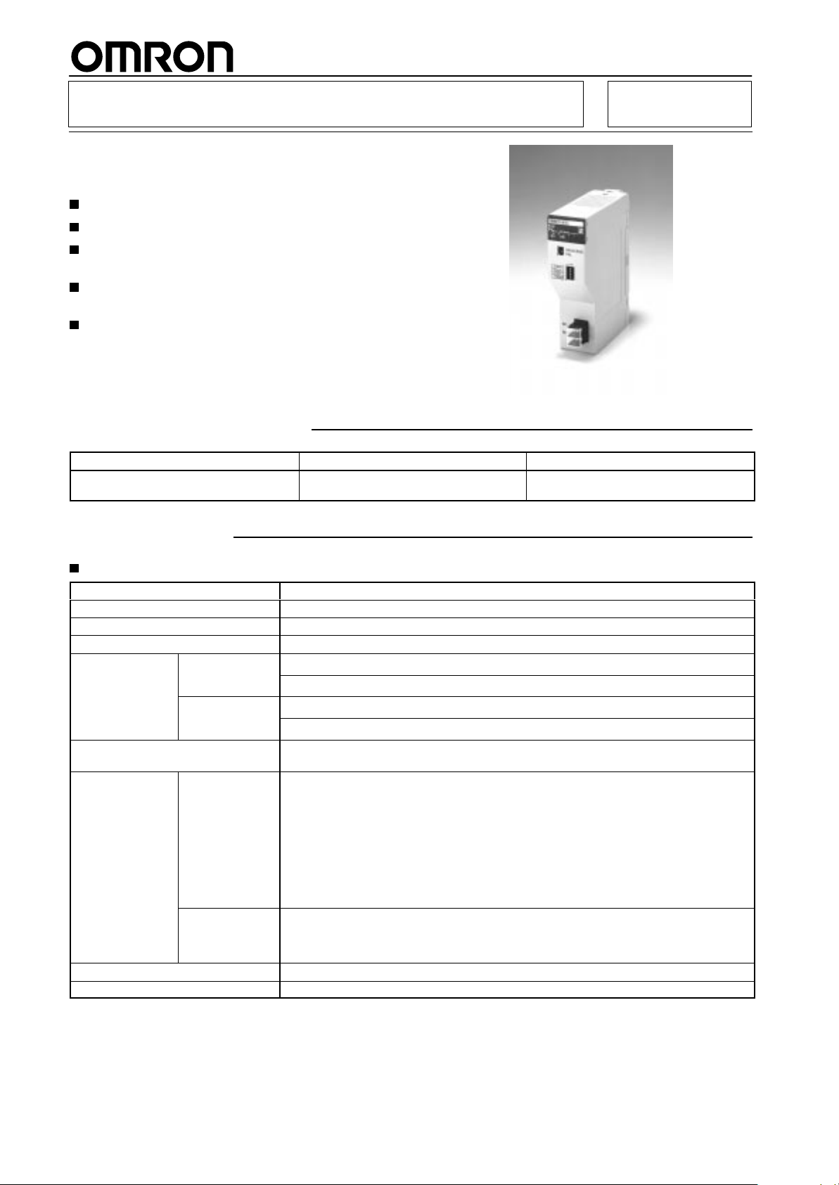
Master Control Unit
usadaoecooeucos
Subminiature, Stand-alone Model with
CompoBus/S Master and SYSMAC
Controller Functions
SRM1-C01-V2/C02-V2
Maximum
number of Remote I/O points per Master:
256
Maximum number of Slaves per Master: 32
Communications
cycle time: 0.5 ms max. (at baud
rate 750 kbps).
Communications distance: Extended to 500 m
max. (at baud rate 93.75 kbps).
Additional instructions (PID, SCL, NEG, ZCP)
ensure analog compatibility.
RS-232C port incorporated (SRM1-C02-V2).
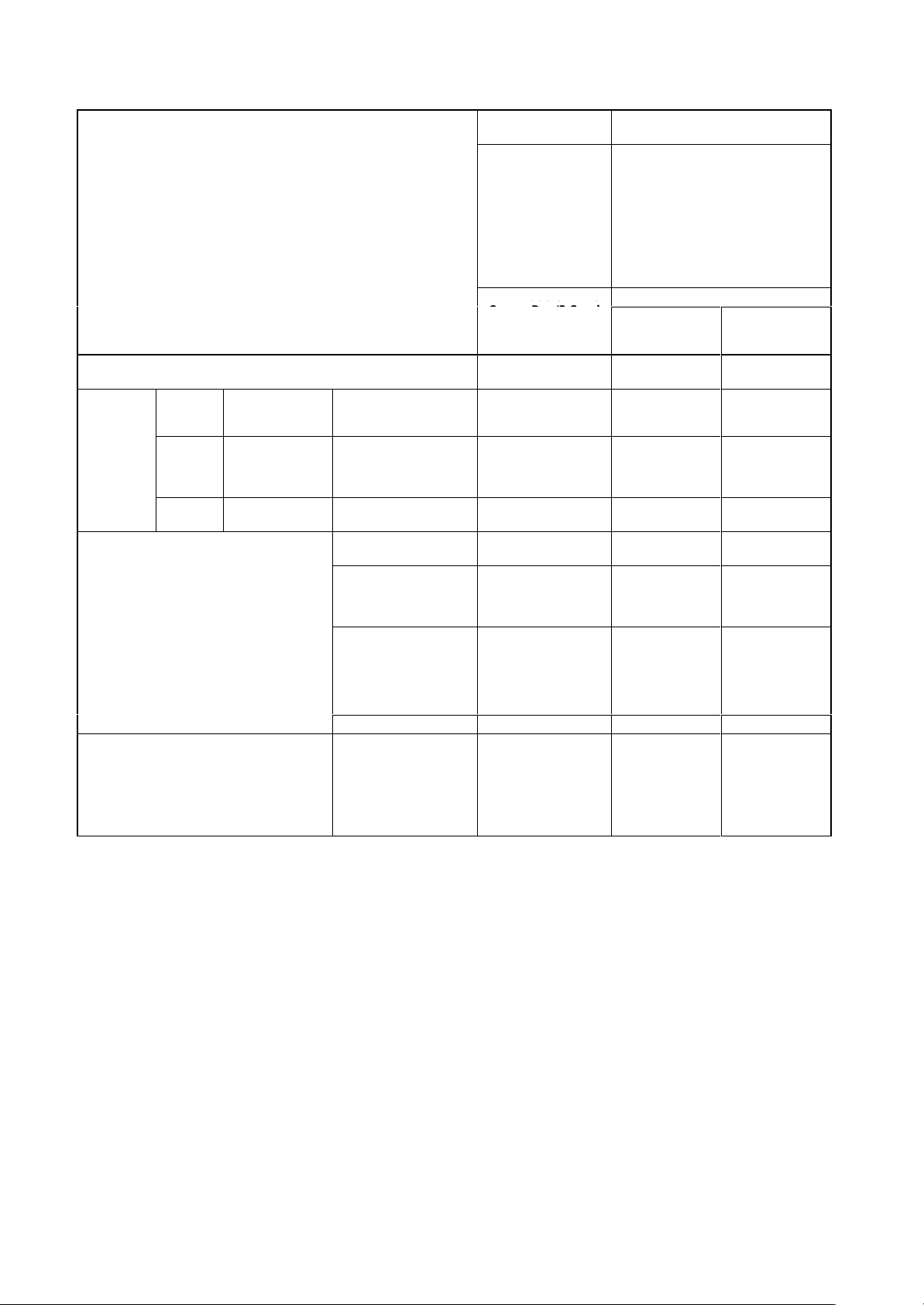
Ordering Information
Specifications Model
Built-in
stand-alone controller functions
Without RS-232C
With RS-232C
Specifications
Master Specifications
Number
Max. number of Slaves per Master
I/O words
Programming language
T
Execution time
Program capacity
Data memory
Timers/Counters
W
Memory backup
Peripheral port
RS-232C port
Programming tool
Note:
of I/O points
ypes of instruction
ork bits
PID, SCL, NEG, and ZCP instructions are not supported by the SYSMAC-CPT
256 points (128 inputs/128 outputs)
128 points (64 inputs/64 outputs)
Selectable by DM setting. The default setting is 256 points.
256 points: 32
128 points: 16
Input words: 000 to 007
Output words: 010 to 017
Ladder diagram
14 basic and 72 special instructions (123 instructions in total)
LD instruction:
MOV instruction:
4,096 words
2,048 + 512 (read-only) words
128 timers/counters
640 bits
Flash memory (without battery): User programs
Super capacitor: Data memory (backed up for 20 days at an ambient temperature of 25
1 point
1 point (SRM1-C02-V1 only)
Host Link, NT Link, 1:1 Link, or no protocol
Programming Consoles: CQM1-PRO01-E, C200H-PRO27-E
SYSMAC-CPT: WS01-CPTB1-E (CD-ROM/FD)
SYSMAC Support Software (MS-DOS version): C500-ZL3A
0.97
9.1
µs
µs
RC
SRM1-C01-V2
SRM1-C02-V2
°C)
T1-E
.
11
Page 3
SRM1-C01-V2/C02-V2
Communications Specifications
Communications
Coding method
Connection method
Communications baud rate
Communications
cycle time
Communications cable
Communications
distance
Max. number of connecting nodes
Error control checks
Note: 1.
2.
method CompoBus/S protocol
Manchester coding method
Multi-drop method and T
750,000 bps/93,750 bps (see note 2)
High-speed
communications
mode
Long-distance
communications
mode
High-speed
communications
mode
Long-distance
communications
mode
A terminator must be connected to the point in the system farthest from the Master
The communications baud rate is switched using DM settings (default setting is 750,000 bps).
0.5 ms with 8 Slaves for inputs and 8 Slaves for outputs
0.8 ms with 16 Slaves for inputs and 16 Slaves for outputs
4.0 ms with 8 Slaves for inputs and 8 Slaves for outputs
6.0 ms with 16 Slaves for inputs and 16 Slaves for outputs
2-conductor VCTF cable (0.75 x 20)
Dedicated flat cable
VCTF cable:
Main line length:
Branch line length:
T
Flat cable:
Main line length:
Branch line length:
T
(When flat cable is used to connect fewer than 16 Slaves, the main line can be up to
100 m long and the total branch line length can be up to 50 m.)
VCTF cable:
Main line length:
Branch line length:
T
32
Manchester code check, frame length check, and parity check
General Specifications
Supply
voltage
Allowable supply voltage
Power consumption
Inrush current
Noise immunity
V
ibration resistance
Shock resistance
Ambient temperature
Humidity
Atmosphere
T
erminal screw size
Power interrupt time
Weight
24 VDC
20.4 to 26.4 VDC
3.5 W max.
12.0 A max.
Conforms to IEC61000-4-4, 2 kV (power lines)
10 to 57 Hz, 0.075-mm amplitude, 57 to 150 Hz, acceleration: 9.8 m/s2 in X, Y
directions for 80 minutes each
(T
ime coef
147 m/s2 three times each in X, Y, and Z directions
Operating: 0°C to 55
Storage: –20°C to 75
10% to 90% (with no condensation)
Must be free from corrosive gas.
M3
DC type: 2 ms min.
150 g max.
-branch method (see note 1)
otal branch line length:
otal branch line length:
otal branch line length:
ficient; 8 minutes × coef
°C
°C
SRM1-C01-V2/C02-V2
100 m max.
3 m max.
50 m max.
30 m max.
3 m max.
30 m max.
500 m max.
6 m max.
120 m max.
.
, and Z
ficient factor 10 = total time 80 minutes)
12
Page 4
SRM1-C01-V2/C02-V2
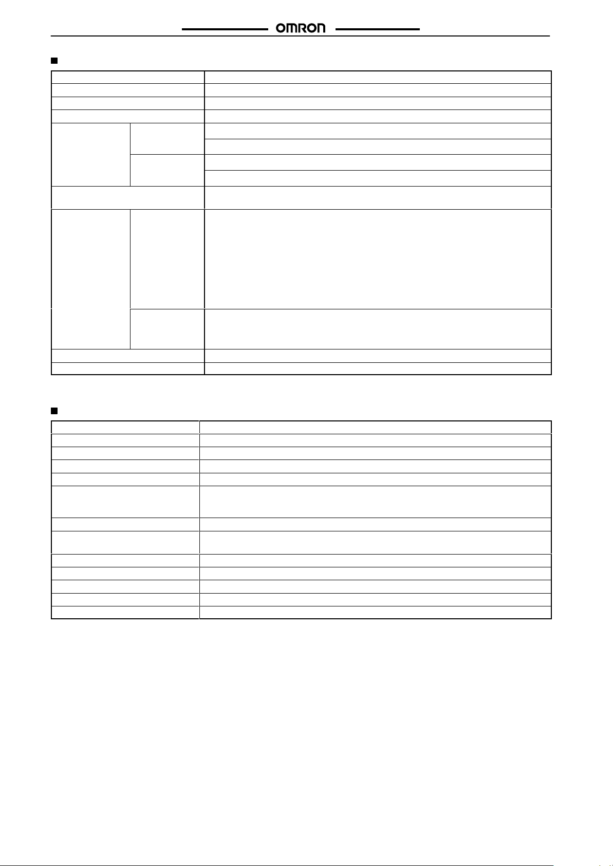
Nomenclature
SRM1-C01-V2/C02-V2
CPU Unit status indicator
CompoBus/S
communications status indicator
Indicates the status of the CompoBus/S in operation and in communication with Slaves.
Peripheral port
communications status indicator
Flashes when the peripheral port or
RS-232C port is in communication.
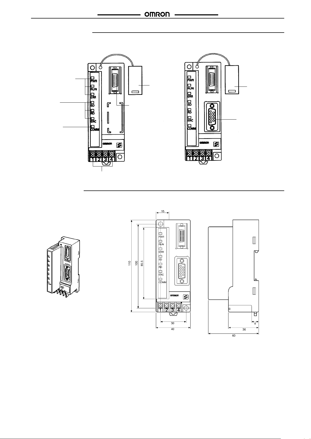
Dimensions
Note: All
units are in millimeters unless otherwise indicated.
SRM1-C01-V2
Terminal block
Connector cover
Peripheral port
Connect this port to programming
tools through dedicated cables.
SRM1-C02-V2
Connector cover
RS-232C port
Connect this port to the
RS-232C interfaces of personal
computers and Programmable
Terminals.
SRM1-C01/C02-V2
The above dimensions apply to the SRM1-C02-V2. The SRM-C01-V2 has no RS-232C port.
13
Page 5
Master Unit
Master Unit for CS1, C200HX, C200HG,
C200HE, and C200HS
A maximum of 256 I/O points available.
Connects to a maximum of 32 Slaves.
Communications
rate 750 kbps).
Communications distance: Extended to 500 m
max. (at baud rate 93.75 kbps).
Connection to Analog Terminals now supported.
Ordering Information
cycle time: 0.5 ms max. (at baud
C200HW-SRM21-V1
RC
PC Max.
C200HX (-Z), C200HG (-Z), C200HE (-Z),
C200HS, CS1
256 points (128 inputs/128 outputs)
Specifications
Communications Specifications
Communications
Coding method
Connection method
Communications baud rate
Communications
cycle time
Communications cable
Communications
distance
Max. number of connecting nodes
Error control checks
Note: 1.
2.
method CompoBus/S protocol
Manchester coding method
Multi-drop method and T
750,000 bps, 93,750 bps (see note 2)
High-speed
communications
mode
Long-distance
communications
mode
High-speed
communications
mode
Long-distance
communications
mode
A terminator must be connected to the point in the system farthest from the Master
The communications baud rate is switched with the DIP switch.
0.5 ms with 8 Slaves for inputs and 8 Slaves for outputs
0.8 ms with 16 Slaves for inputs and 16 Slaves for outputs
4.0 ms with 8 Slaves for inputs and 8 Slaves for outputs
6.0 ms with 16 Slaves for inputs and 16 Slaves for outputs
2-conductor VCTF cable (0.75 x 20)
Dedicated flat cable
VCTF cable:
Main line length:
Branch line length:
T
Flat cable:
Main line length:
Branch line length:
T
(When flat cable is used to connect fewer than 16 Slaves, the main line can be up to
100 m long and the total branch line length can be up to 50 m.)
VCTF cable:
Main line length:
Branch line length:
T
32
Manchester code check, frame length check, and parity check
number of I/O points
-branch method (see note 1)
otal branch line length:
otal branch line length:
otal branch line length:
Model
C200HW-SRM21-V1
100 m max.
3 m max.
50 m max.
30 m max.
3 m max.
30 m max.
500 m max.
6 m max.
120 m max.
.
14
Page 6
C200HW-SRM21-V1
Unit Specifications
Current
consumption
Number of I/O points
Number of occupied words
PC CS1, C200HX (-ZE), C200HG (-ZE), C200HE (-ZE), C200HS
Number of points per node number
Max. number of Slaves per Master
Status data
Weight
Approved standards
Note:
These flags use the AR area.
150 mA max. at 5 VDC
256 points (128 inputs/128 outputs), 128 points (64 inputs/64 outputs) (switchable)
256 points:
128 points:
8 points
32
Communications Error Flag and Active Slave Node (see note)
200 g max.
UL 508 (E95399), CSA C22.2 No. 142 (LR51460)
20 words (8 input words/8 output words, 4 status data)
10 words (4 input words/4 output words, 2 status data)
Ratings
The
ratings of the Unit are the same as those of the CS1, C200HX, C200HG, C200HE, and C200HS.
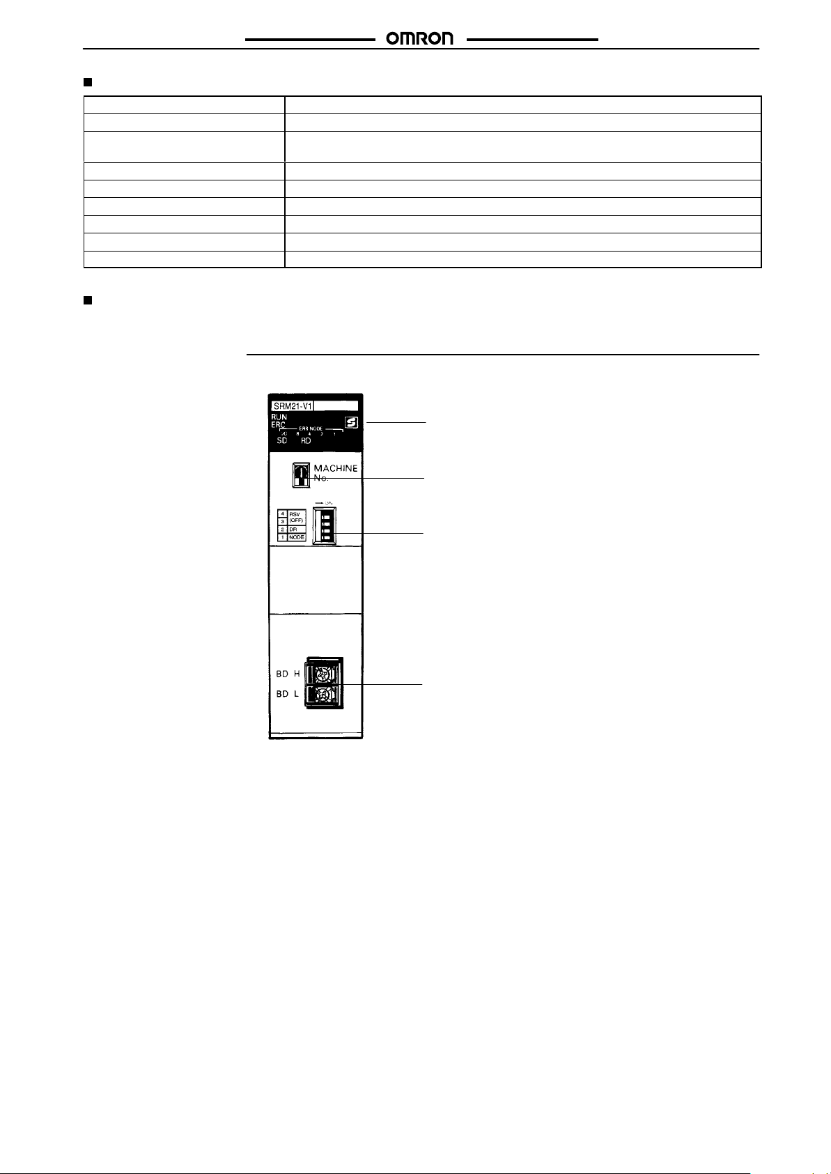
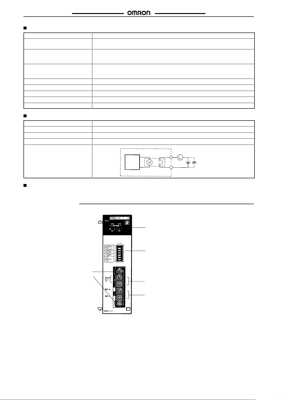
Nomenclature
Indicators
Indicates the operating status of the Master Unit and
the status of communications with the Slaves.
C200HW-SRM21-V1
Rotary Switch
This switch sets the Master’
unit number
DIP Switch
These pins have the following functions:
Pin 1:
Pin 2:
Pins 3 to 4:
Communications T
Connect the Slaves’ transmission cable to
these terminals.
.
Max. number of Slaves setting
Baud rate setting
Reserved (Always OFF.)
s one-digit hexadecimal
erminals
15
Page 7
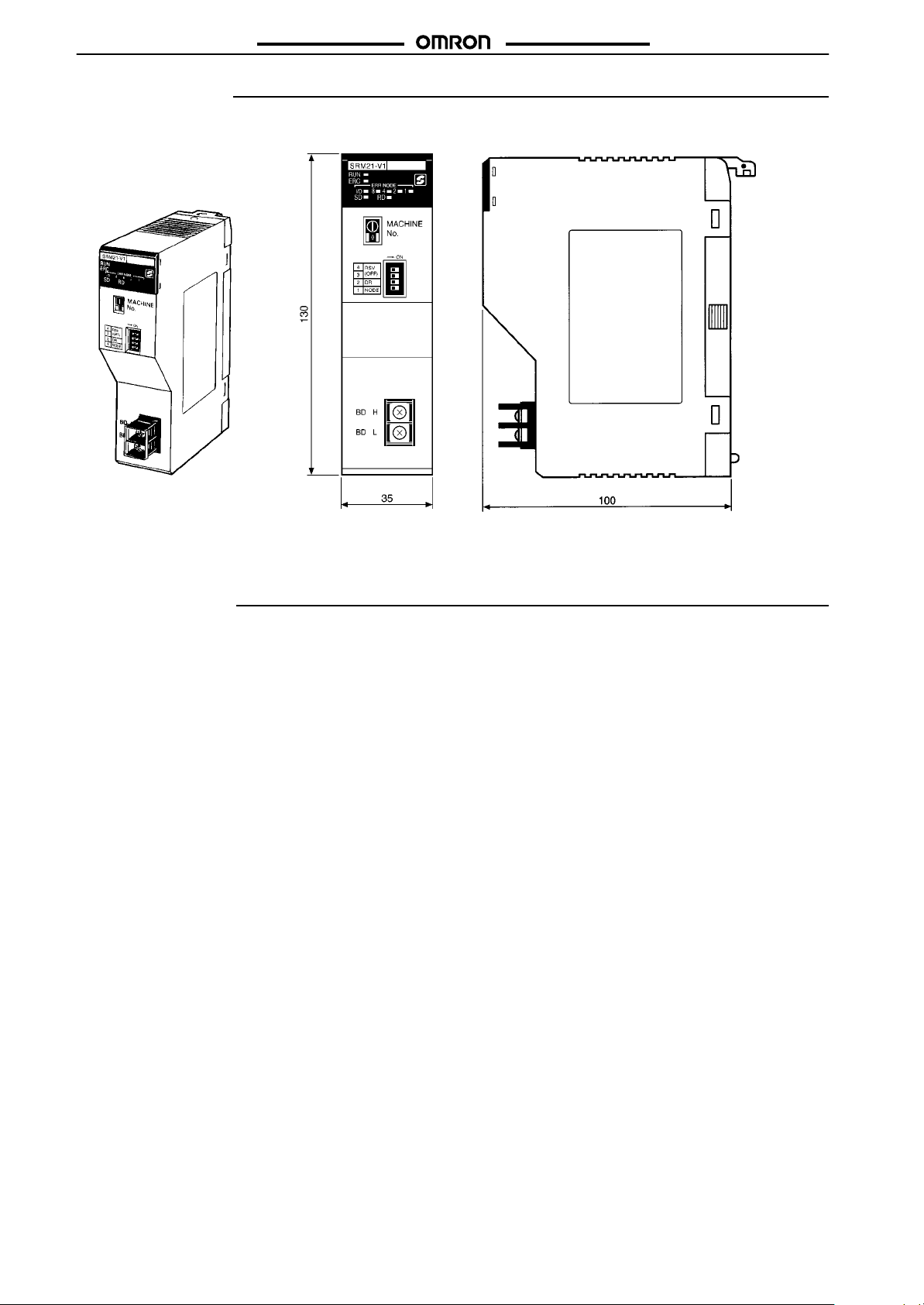
C200HW-SRM21-V1
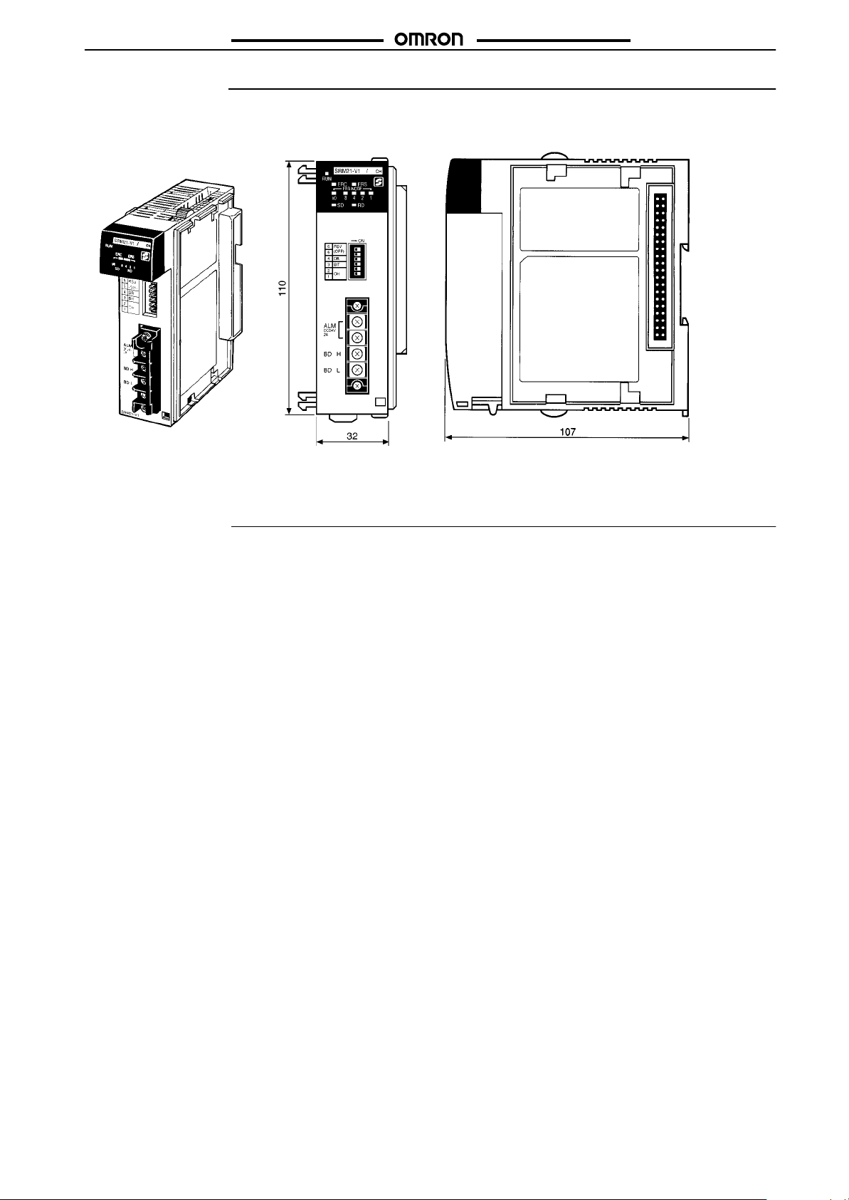
Dimensions
Note:
All units are in millimeters unless otherwise indicated.
C200HW-SRM21-V1
C200HW-SRM21-V1
Precautions
Refer to the
the Unit.
CompoBus/S Operation Manual (W266)
Note: Refer to the
on the dimensions when the Master Unit is installed in the PC’
details
before using
C200HX, C200HG, C200HE, C200HS,
or
CS1 Operation Manual
s Backplane.
for
16
Page 8
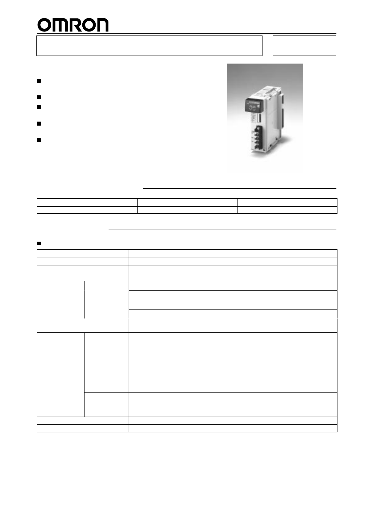
Master Unit
Master Unit for CQM1
A
maximum
set 32, 64, or 128 I/O points).
Connects to a maximum of 16/32 Slaves.
Communications
rate 750 kbps).
Communications distance: Extended to 500 m
max. (at baud rate 93.75 kbps).
Connection to Analog Terminals now supported.
Ordering Information
of 128 I/O points available (Possible to
cycle time: 0.5 ms max. (at baud
CQM1-SRM21-V1
RC
PC Max.
CQM1-series PC
128 points (64 inputs/64 outputs)
Specifications
Communications Specifications
Communications
Coding method
Connection method
Communications baud rate
Communications
cycle time
Communications cable
Communications
distance
Max. number of connecting nodes
Error control checks
Note: 1.
2.
method CompoBus/S protocol
Manchester coding method
Multi-drop method and T
750,000 bps, 93,750 bps (see note 2)
High-speed
communications
mode
Long-distance
communications
mode
High-speed
communications
mode
Long-distance
communications
mode
A terminator must be connected to the point in the system farthest from the Master
The communications baud rate is switched with the DIP switch.
0.5 ms with 8 Slaves for inputs and 8 Slaves for outputs
0.8 ms with 16 Slaves for inputs and 16 Slaves for outputs
4.0 ms with 8 Slaves for inputs and 8 Slaves for outputs
6.0 ms with 16 Slaves for inputs and 16 Slaves for outputs
2-conductor VCTF cable (0.75 x 20)
Dedicated flat cable
VCTF cable:
Main line length:
Branch line length:
T
Flat cable:
Main line length:
Branch line length:
T
(When flat cable is used to connect fewer than 16 Slaves, the main line can be up to
100 m long and the total branch line length can be up to 50 m.)
VCTF cable::
Main line length:
Branch line length:
T
32
Manchester code check, frame length check, and parity check
number of I/O points
-branch method (see note 1)
otal branch line length:
otal branch line length:
otal branch line length:
Model
CQM1-SRM21-V1
100 m max.
3 m max.
50 m max.
30 m max.
3 m max.
30 m max.
500 m max.
6 m max.
120 m max.
.
17
Page 9
CQM1-SRM21-V1
Unit Specifications
Current
consumption
Number of I/O points
Number of occupied words
PC
Number of points per node number
Max. number of Slaves per Master
Status data
Weight
Approved standards
180 mA max. at 5 VDC
128 points (64 inputs/64 outputs), 64 points (32 inputs/32 outputs),
32 points (16 inputs/16 outputs) (switchable)
128 points:
64 points:
32 points: 1 input word/1 output word
128 points:
64 points:
32 points:
4/8 points (switchable)
32 (4 points per node number)
Alarm terminal output
200 g max.
UL 508 (E95399), CSA C22.2 No. 142 (LR51460)
Alarm Output Specifications
Maximum
Minimum switching capacity
Relay G6D-1A
Minimum ON time
Circuit configuration
switching capacity
2 A at 24 VDC
10 mA at 5 VDC
100 ms
CQM1-SRM21-V1
4 input words/4 output words
2 input words/2 output words
CQM1-CPU41-EV1/CPU42-EV1/CPU43-EV1/CPU44-EV1
CQM1-CPU11-E/CPU21-E/CPU41-EV1/CPU42-EV1/CPU43-EV1/CPU44-EV1
CQM1-CPU11-E/CPU21-E/CPU41-EV1/CPU42-EV1/CPU43-EV1/CPU44-EV1
CQM1-SRM21-V1
Ratings
The
ratings of the Unit are the same as those for the CQM1.
Nomenclature
erminal block screws
T
These screws attach the terminal
block. The terminal block can be
removed when these screws are
loosened.
Internal
circuit
2 A at 24 VDC max.
Indicators
Indicates the operating status of the Master Unit and
the status of communications with the Slaves.
DIP Switch
These pins have the following functions:
Pins 1 and 2:
Pin 3:
Pin 4:
Pins 5 to 6:
Alarm Output Terminals
These terminals are shorted when an error occurs.
Connect to a warning device.
Communications T
Connect the Slaves’ transmission cable to these
terminals.
PC word allocation setting
Number of points setting
Baud rate setting
Reserved (Always OFF.)
erminals
18
Page 10
CQM1-SRM21-V1
Dimensions
Note:
All units are in millimeters unless otherwise indicated.
CQM1-SRM21-V1
CQM1-SRM21-V1
Precautions
Refer to the
the Unit.
CompoBus/S Operation Manual (W266)
Note: Refer
the
Master Unit is installed in the PC’
to the
CQM1 Operation Manual
before using
for details on the dimensions when
s Backplane.
19
Page 11
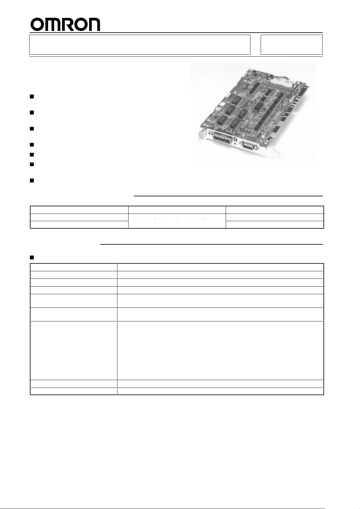
SYSMAC Board
56 o s ( 8 u s/ 8 ou u s)
SYSMAC C200HX/HG/HE and
CompoBus/S Master Functions
Integrated into a Single PCB
C200PC-ISAj2-SRM
Operates
as a Programmable Controller to be built
into personal computers.
Programming is possible through Programming
Devices like the programming on C200HX/HG.
An
optional Expansion
Board is available for serial
communications.
Dedicated library in C is available for control.
Driver for Windows use is available.
Connects to a maximum of three Expansion I/O
Racks.
CompoBus/S Slave data is automatically read.
Ordering Information
C200HG-CPU43
C200HX-CPU64
PC Max.
256 points (128 inputs/128 outputs)
number of I/O points
Specifications
Communications Specifications
Communications
Coding method
Connection method
Communications baud rate
Communications cycle time
Communications cable
Communications distance
Max. number of connecting nodes
Error control checks
Note:
A terminator must be connected to the point in the system farthest from the Master
method CompoBus/S protocol
Manchester coding method
Multi-drop method and T
750,000 bps
0.5 ms with 8 Slaves for inputs and 8 Slaves for outputs
0.8 ms with 16 Slaves for inputs and 16 Slaves for outputs
2-conductor VCTF cable (0.75 x 20)
Dedicated flat cable
VCTF cable:
Main line length:
Branch line length:
T
otal branch line length:
Flat cable:
Main line length:
Branch line length:
T
otal branch line length:
(When flat cable is used to connect fewer than 16 Slaves, the main line can be up to
100 m long and the total branch line length can be up to 50 m.)
32
Manchester code check, frame length check, and parity check
-branch method (see note)
Model
C200PC-ISA02-SRM
C200PC-ISA12-SRM
100 m max.
3 m max.
50 m max.
30 m max.
3 m max.
30 m max.
.
20
Page 12

C200PC-ISAj2-SRM
Unit Specifications
Power
supply voltage
Current consumption
Number of I/O points
Number of occupied words
Number of points per node number
Max. number of Slaves per Master
Status data
Weight
Note: 1.
The current consumption will be 0.8 A max. if the Programming Console is connected through the optional Expansion Board.
2.
The occupied words are in the IR area.
C200PC-ISAj2-SRM
4.875 to 5.25 VDC
0.5 A max. (see note 1)
256 points (128 inputs/128 outputs), 128 points (64 inputs/64 outputs), (switchable)
256 points:
128 points:
8 points
32
Communications Error Flag and Active Slave Node (see note 2)
200 g max.
20 words (8 input words, 8 output words, and 4 status data words) (see note 2)
10 words (4 input words, 4 output words, and 2 status data words)
21
Page 13
I/O Link Unit
30 oint I/O model
18
12
DC
DC
40 oint I/O model
24
16
DC
DC
60 oint I/O model
36
24
DC
Ex ansion I/O Units
3 max. (see note)
12
8
8
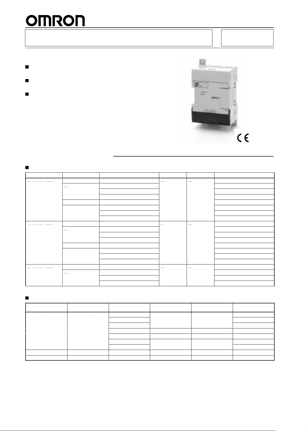
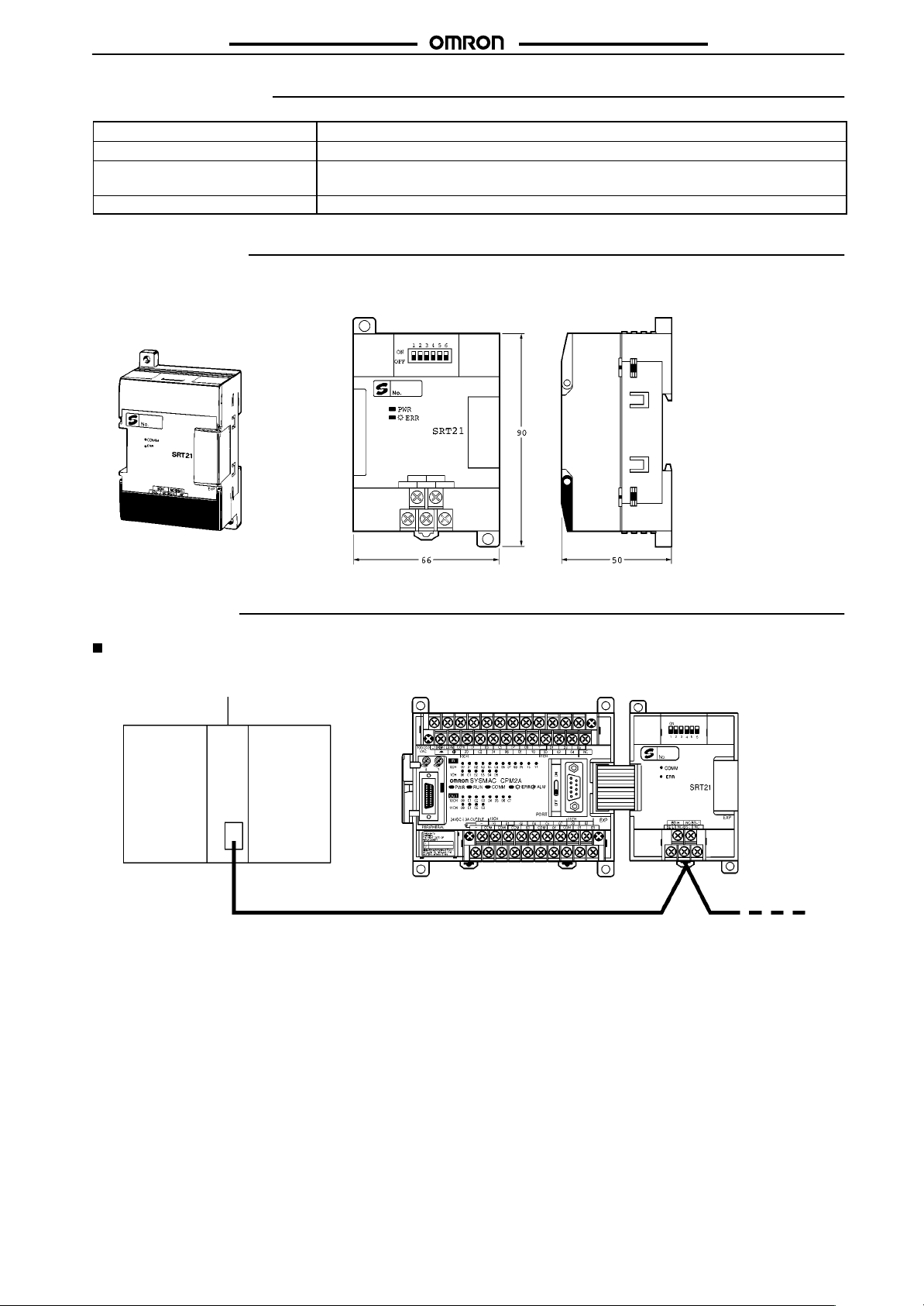
CPM1A-SRT21
I/O Link Unit for CPM2A/CPM1A
Operates as a Slave of the CompoBus/S Master
Unit.
Exchanges eight inputs and eight outputs with the
Master.
Approved
by UL and CSA standards,
and bears the
CE marking.
Ordering Information
CPU Units
I/O configuration Power supply Output method Input Output Model
30-point I/O model
40-point I/O model
60-point I/O model
Note: Models
AC Relay
DC
AC Relay CPM2A-30CDR-A
DC
AC Relay
DC
AC Relay CPM2A-40CDR-A
DC
AC Relay
DC
Relay
Transistor (sink) CPM1A-30CDT-D
Transistor (source) CPM1A-30CDT1-D
Relay CPM2A-30CDR-D
Transistor (sink) CPM2A-30CDT-D
Transistor (source) CPM2A-30CDT1-D
Relay
Transistor (sink) CPM1A-40CDT-D
Transistor (source) CPM1A-40CDT1-D
Relay CPM2A-40CDR-D
Transistor (sink) CPM2A-40CDT-D
Transistor (source) CPM2A-40CDT1-D
Relay
Transistor (sink) CPM2A-60CDT-D
Transistor (source) CPM2A-60CDT1-D
marked with asterisks do not bear CE markings.
Expansion Units
Product Number of connectable
Expansion I/O Units 3 max. (see note)
Analog I/O Unit 3 max. (see note) Analog 2 1 CPM1A-MAD01
CompoBus/S I/O Link Unit 3 max. (see note) --- 8 I/O link points 8 I/O link points CPM1A-SRT21
Note: Only
a single Unit will be connectable if the NT
Units per CPU Unit
Output method Input Output Model
Relay
Transistor (sink)
Transistor (source) CPM1A-20EDT1
--- 8 --- CPM1A-8ED
Relay --- 8 CPM1A-8ER
Transistor (sink)
Transistor (source)
-AL001 is connected to the RS-232C port.
18 12
24 16
36 24
12 8
--- 8
CPM1A-30CDR-A*
CPM1A-30CDR-D*
CPM1A-40CDR-A*
CPM1A-40CDR-D*
CPM2A-60CDR-A
CPM2A-60CDR-D
CPM1A-20EDR1
CPM1A-20EDT
CPM1A-8ET
CPM1A-8ET1
RC
22
Page 14
CPM1A-SRT21
Specifications
CPM1A-SRT21
Slave
Number of I/O points
Number of occupied I/O memory
words of CPM2A
Node address setting
CompoBus/S Slave
8 inputs and 8 outputs
1 input word and 1 output word (same as other Expansion Units in allocation)
DIP switch
Dimensions
Note:
All units are in millimeters unless otherwise indicated.
CPM1A-SRT21
Installation
Connection Examples
CompoBus/S Master Unit or
SRM1 CompoBus/S Master
Control Unit
CS1j
C200Hj
CQM1
SRM1
Note: A
single CompoBus/S I/O Link Unit together with a maximum of two other Expansion
CPM2A CPU Unit.
CPM1A or CPM2A CPU Unit
Dedicated flat cable or VCTF cable Connectable to 16 Units max.
CPM1A-SRT21 CompoBus/S
I/O Link Unit
(Eight CQM1-SRM21 Units max.)
I/O Units can be connected to the CPM1A or
23
Page 15
Transistor Remote Terminal
u
C
C
u
8
Ou u
u
6
Ou u
Long-distance Communications
Supported by SRT2 Models
(Long-distance/High-speed
Communications Selection)
SRT1
models support high-speed communications
only.
SRT2 models support long-distance communications and high-speed communications.
Ultra-compact at 80 x 48 x 50 (W x H x D) mm for
4-point
and 8-point terminals and 105 x 48 x 50 (W
H x D) mm for 16-point terminals.
Two independent power supplies can be used
because the I/O terminals are insulated from the
internal circuits.
DIN track mounting and screw mounting are both
supported.
Ordering Information
I/O
classification
Input
Output
Input
Output
Input
Output
Note:
For more details about connections supported by the Master Unit, refer to page
Internal I/O circuit
common
NPN (+ common)
PNP (– common)
NPN (– common)
PNP (+ common)
NPN (+ common)
PNP (– common)
NPN (– common)
PNP (+ common)
NPN (+ common)
PNP (– common)
NPN (– common)
PNP (+ common)
I/O points
4 24 VDC 24 VDC
8
16
x
Rated voltage
I/O rated voltage
10.
SRTj-ID/OD
RC
Model
SRT1-ID04
SRT1-ID04-1
SRT1-OD04
SRT1-OD04-1
SRT2-ID08
SRT2-ID08-1
SRT2-OD08
SRT2-OD08-1
SRT2-ID16
SRT2-ID16-1
SRT2-OD16
SRT2-OD16-1
Specifications
Ratings
Inputs
Input
current
ON delay time 1.5 ms max.
OFF delay time
ON voltage
OFF voltage
OFF current
Insulation method
Input indicators
24
6 mA max./point
1.5 ms max.
15 VDC min. between each input terminal and V
5 VDC max. between each input terminal and V
1 mA max.
Photocoupler
LED (yellow)
Page 16
SRTj-ID/OD
Outputs
Rated output current
Residual voltage
Leakage current
Insulation method
Output indicators
Characteristics
Communications
voltage
I/O power supply voltage
I/O power supply current
Current consumption (see note)
Connection method
Connecting Units
Dielectric strength
Noise immunity
V
ibration resistance
Shock resistance
Mounting strength
T
erminal strength
Screw tightening torque
Ambient temperature
Ambient humidity
Weight
Approved standards (4/8 points)
Note: The
sensor
power supply
above current consumption is the value with all 4 and 8 and 16 points turned ON excluding the current consumption of the external
connected to the input Remote T
0.3 A/point
0.6 V max.
0.1 mA max.
Photocoupler
LED (yellow)
14 to 26.4 VDC
24 VDC
1 A max.
50 mA max. at 24 VDC
Multi-drop method and T
Secondary branches cannot be connected to T
4-point and 8-point T
16-point T
500 V
Conforms to IEC61000-4-4, 2 kV (power lines)
10 to 55 Hz, 1.5-mm double amplitude
Malfunction:
Destruction:
No damage when 50 N pull load was applied for 10 s in all directions
No damage when 50 N pull load was applied for 10 s
0.6 to 1.18 N S m
Operating: 0°
Storage: –20°
Operating:
4-point and 8-point T
16-point T
UL 508, CSA C22.2 No. 14
+10%
/
–15%
-branch method
erminals:
erminals:
AC for 1 min (1-mA sensing current between insulated circuits)
2
200 m/s
2
300 m/s
C to 55°C (with no icing or condensation)
C to 65°C (with no icing or condensation)
35% to 85%
erminals: 1
erminal and the current consumption of the load connected to the output Remote T
erminals:
16 Input T
8 Input T
80 g max.
10 g max.
-branch lines.
erminals and 16 Output T
erminals and 8 Output T
erminals per Master
erminals per Master
SRTj-ID/OD
erminal.
25
Page 17
SRTj-ID/OD
Nomenclature
DIP Switch
Used for node number setting and holding or clearing outputs for communications error
Refer to the Compobus/S Operation Manual (W266) for details on DIP switch settings.
Output HOLD/CLEAR settings (Output Terminals only)
Baud rate setting
PWR
COMM
ERR
0
to 7
Screw
mounting hole
I/O Terminals
I/O Power Supply T
Connect 24-VDC power supply
Communications Power Supply T
Connect 14- to 26.4-VDC power supply
CompoBus/S T
Connect the CompoBus/S
communications cable.
.
erminals
erminal
SRTj-ID/OD
erminals
.
Node Number Settings
Indicators
Indicator Display Color Meaning
PWR Lit Green The
Not lit
COMM Lit Yellow
Not lit
ERR Lit Red
Not lit
0 to 7
Lit Yellow
Not lit
communications power supply is ON.
The communications power supply is OFF
Normal communications
A communications error has occurred or the Unit is in standby status.
A communications error has occurred.
Normal communications or the Unit is in standby status.
The corresponding I/O signal is ON.
The corresponding I/O signal is OFF
.
Output HOLD/CLEAR Mode
Mode Pin
HOLD ON
CLEAR OFF
Note: 1. Pin 1 is factory-set to OFF.
This function is available to Output T
2.
1
Setting
Output status is maintained.
Output status is cleared when a communications error occurs.
erminals only
.
.
26
Page 18
SRTj-ID/OD
Node Number Settings
Node
number
0 OFF OFF OFF OFF
1 OFF OFF OFF ON
2 OFF OFF ON OFF
3 OFF OFF ON ON
4 OFF ON OFF OFF
5 OFF ON OFF ON
6 OFF ON ON OFF
7 OFF ON ON ON
8 ON OFF OFF OFF
9 ON OFF OFF ON
10 ON OFF ON OFF
11 ON OFF ON ON
12 ON ON OFF OFF
13 ON ON OFF ON
14 ON ON ON OFF
15 ON ON ON ON
Note: 1.
The node number is factory-set to 0.
2.
For node number settings, refer to the
Pin 3 Pin 4 Pin 5 Pin 6
8 4 2 1
CompoBus/S Operation Manual (W266).
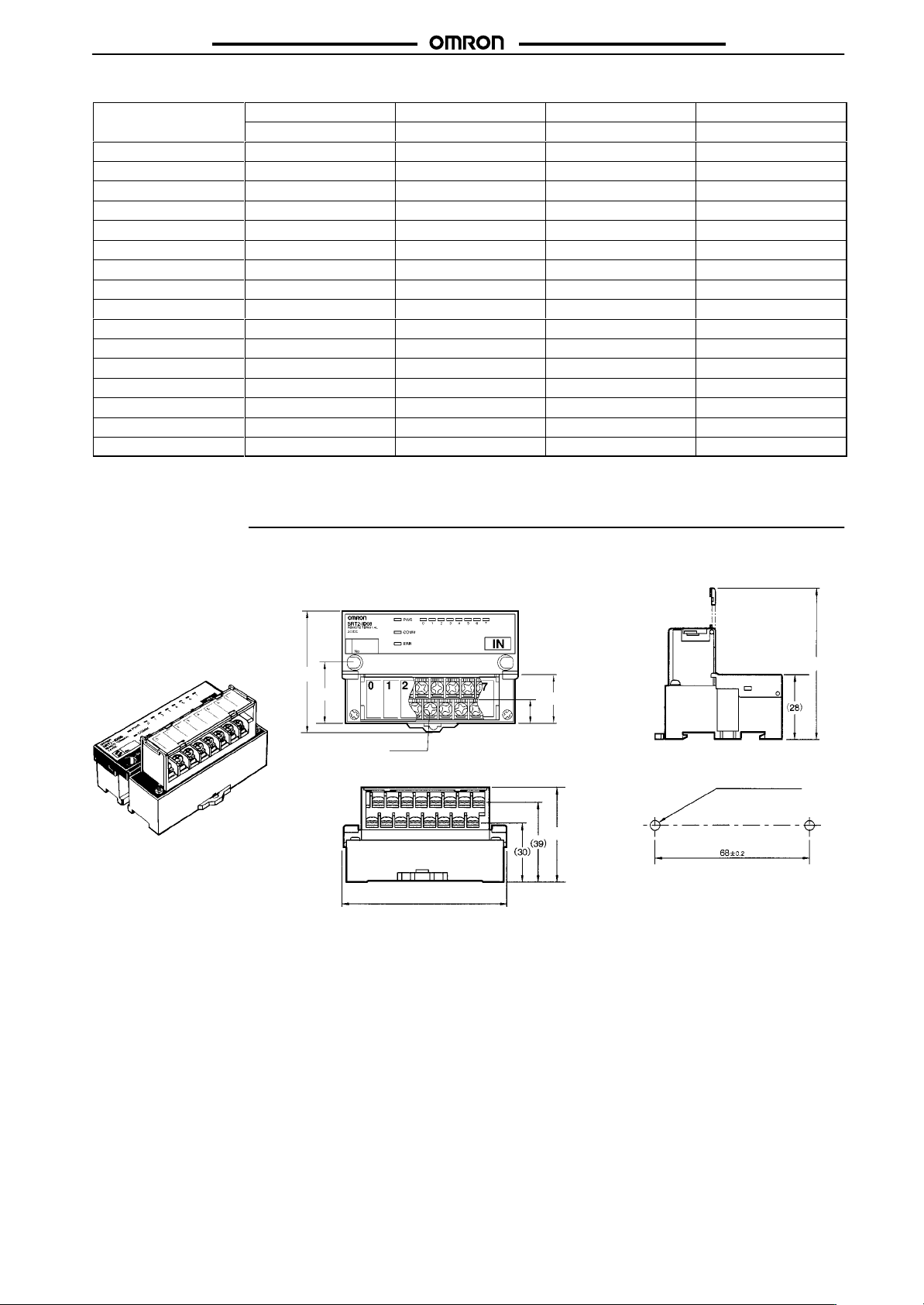
SRTj-ID/OD
Dimensions
Note:
All units are in millimeters unless otherwise indicated.
SRT1-ID04 (-1)
SRT1-OD04 (-1)
SRT2-ID08 (-1)
SRT2-OD08 (-1)
(54)
27
65
(20.5)
(11)
Sixteen, M3
Mounting Holes
Two, 4.2 dia. or M4
48
80
27
Page 19
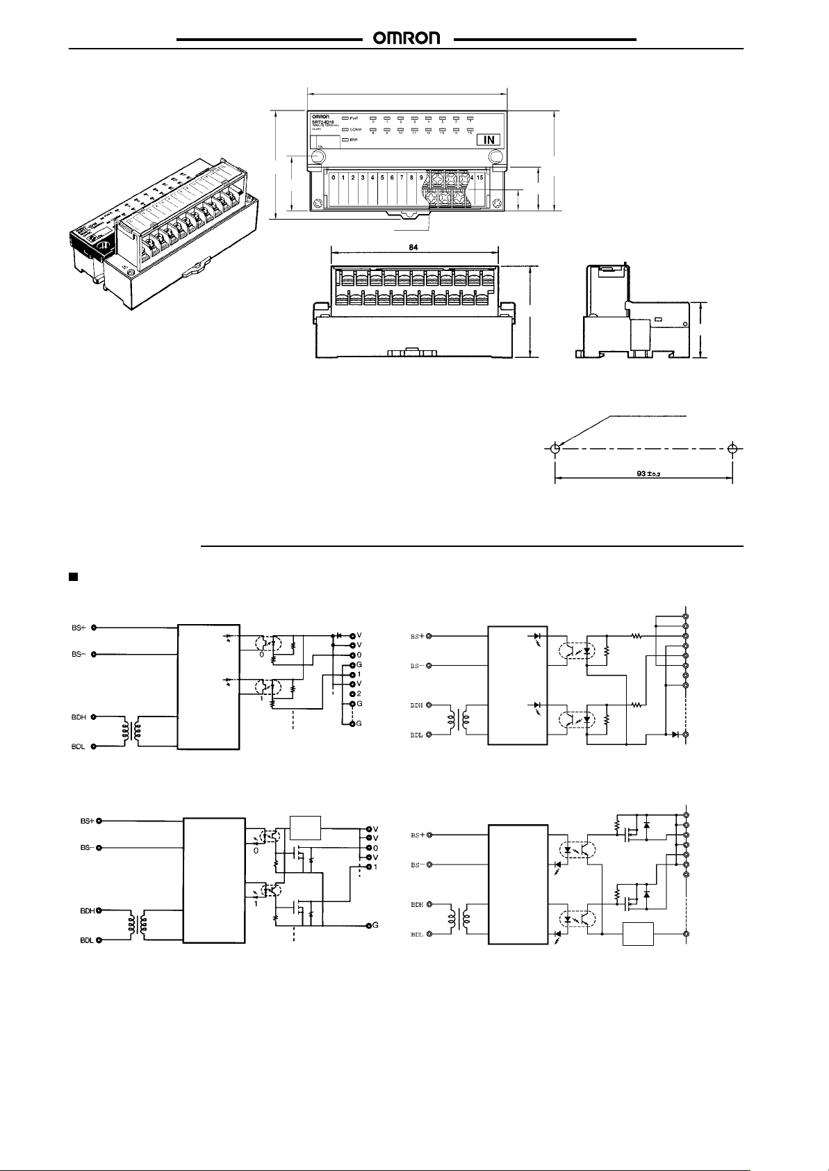
SRTj-ID/OD
SRTj-ID/OD
SRT2-ID16 (-1)
SRT2-OD16 (-1)
(54)
105
(11)
50
(20.5)
48
(28)
(50)
27
22–M3
Mounting Holes
Two, 4.2 dia. or M4
Installation
Internal Circuit Configuration
SRT1-ID04 SRT1-ID04-1
SRT1-OD04
Internal
circuit
Internal
circuit
Photocoupler
Photocoupler
Photocoupler
Photocoupler
Voltage
stepdown
24 VDC(+)
(–)
SRT1-OD04-1
24 VDC
Internal
circuit
Internal
circuit
Photocoupler
Photocoupler
Photocoupler
Photocoupler
Voltage
stepdown
24 VDC (P)
V
V
0
G
1
V
2
G
(P)
G
24 VDC (P)
V
V
0
V
1
V
2
(P)
G
28
Page 20
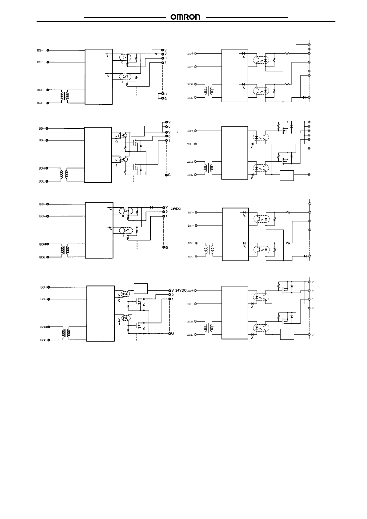
SRTj-ID/OD
SRT2-ID08 SRT2-ID08-1
Internal
circuit
Photocoupler
Photocoupler
24 VDC(+)
Internal
circuit
Photocoupler
Photocoupler
SRTj-ID/OD
24 VDC (P)
V
V
0
1
2
G
SRT2-OD08
SRT2-ID16
Internal
circuit
Internal
circuit
Photocoupler
Photocoupler
Photocoupler
Photocoupler
Voltage
stepdown
(–)
24 VDC
SRT2-OD08-1
SRT2-ID16-1
Internal
circuit
Internal
circuit
Photocoupler
Photocoupler
Photocoupler
Photocoupler
Voltage
stepdown
(P)
G
24 VDC (P)
V
V
0
V
1
2
G
(P)
24 VDC (P)
V
0
1
2
(P)
G
SRT2-OD16
Internal
circuit
Photocoupler
Photocoupler
Voltage
stepdown
SRT2-OD16-1
Internal
circuit
Photocoupler
Photocoupler
Voltage
stepdown
24 VDC (P)
(P)
29
Page 21
SRTj-ID/OD
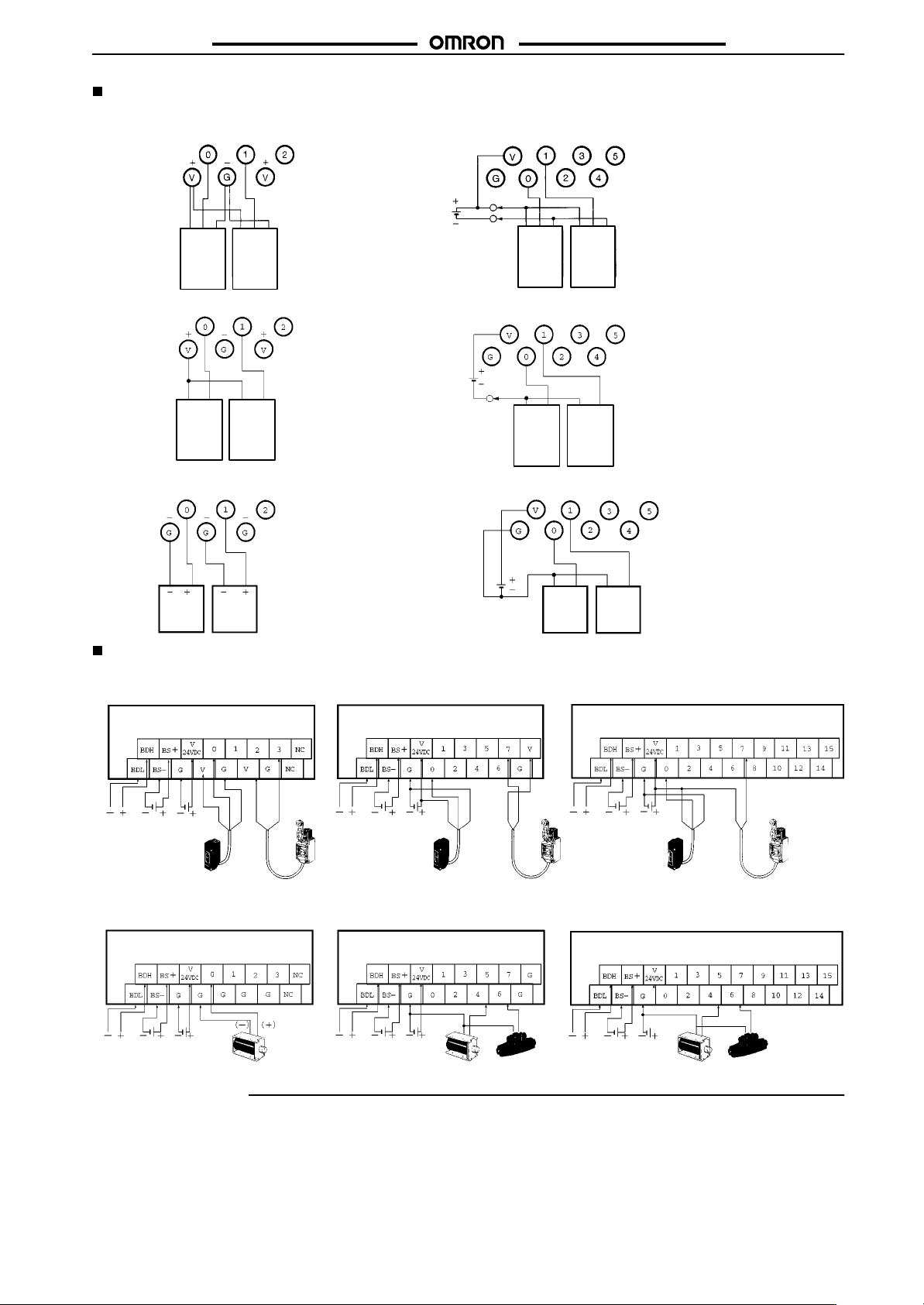
External Connections (NPN Models)
Input
Three-wired Sensors
SRT1-ID04 with NPN Output
SRTj-ID/OD
SRT2-ID08 and SRT2-ID16 with NPN Output
Brown
Sensor
Black
Blue
1
Black
Brown
Sensor 2
Blue
Black
Brown
Sensor 1
Blue
Black
Brown
Sensor 2
Blue
Two-wired Sensors
SRT1-ID04
Brown
Sensor
Blue
1
Brown
Sensor 2
SRT2-ID08
Blue
and SRT2-ID16
Blue
Brown
Sensor 1
Sensor 2
Brown
Blue
Output
SRT1-OD04 SRT2-OD08
L 1 L 2
and SRT2-ID16
L
1
L 2
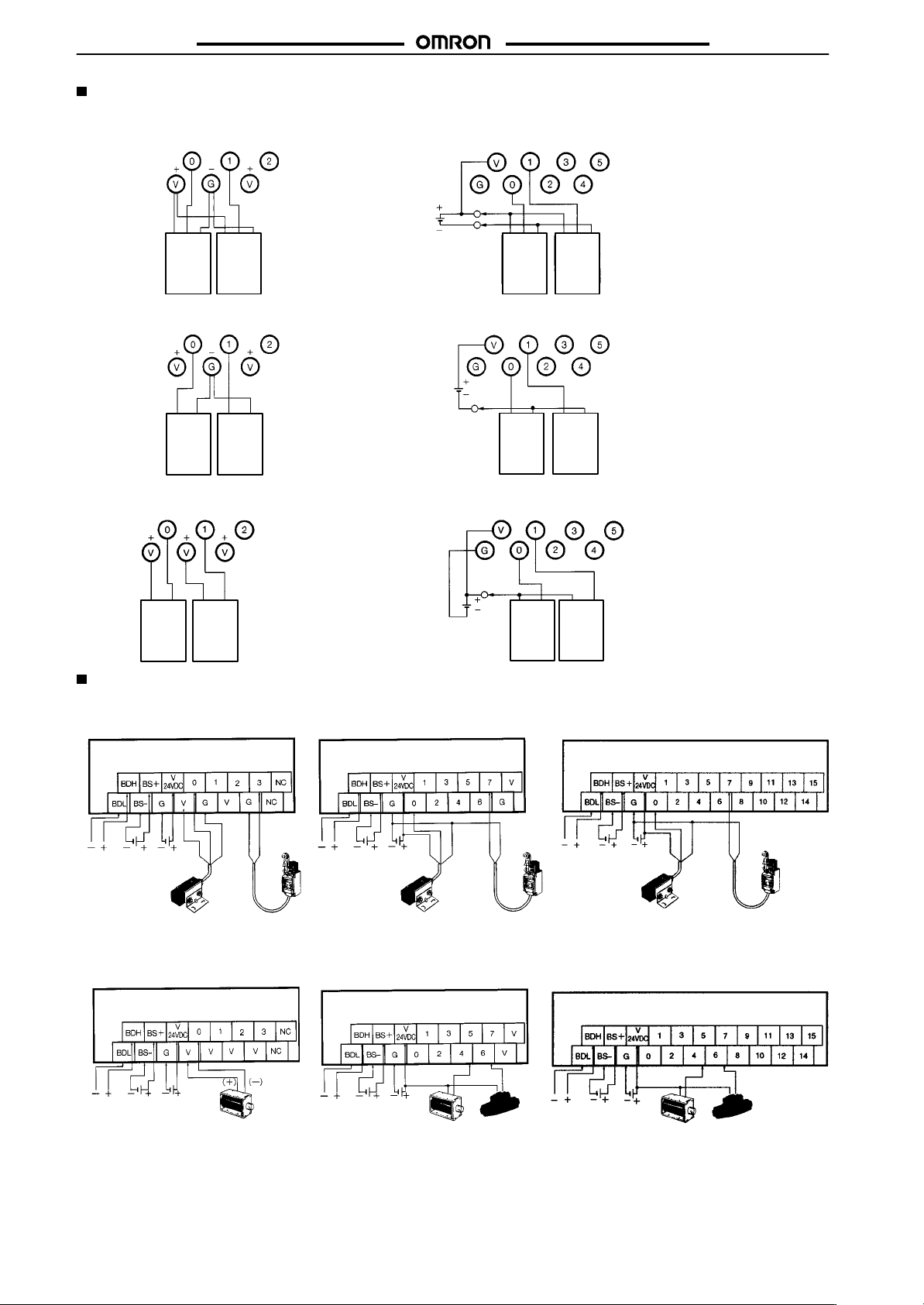
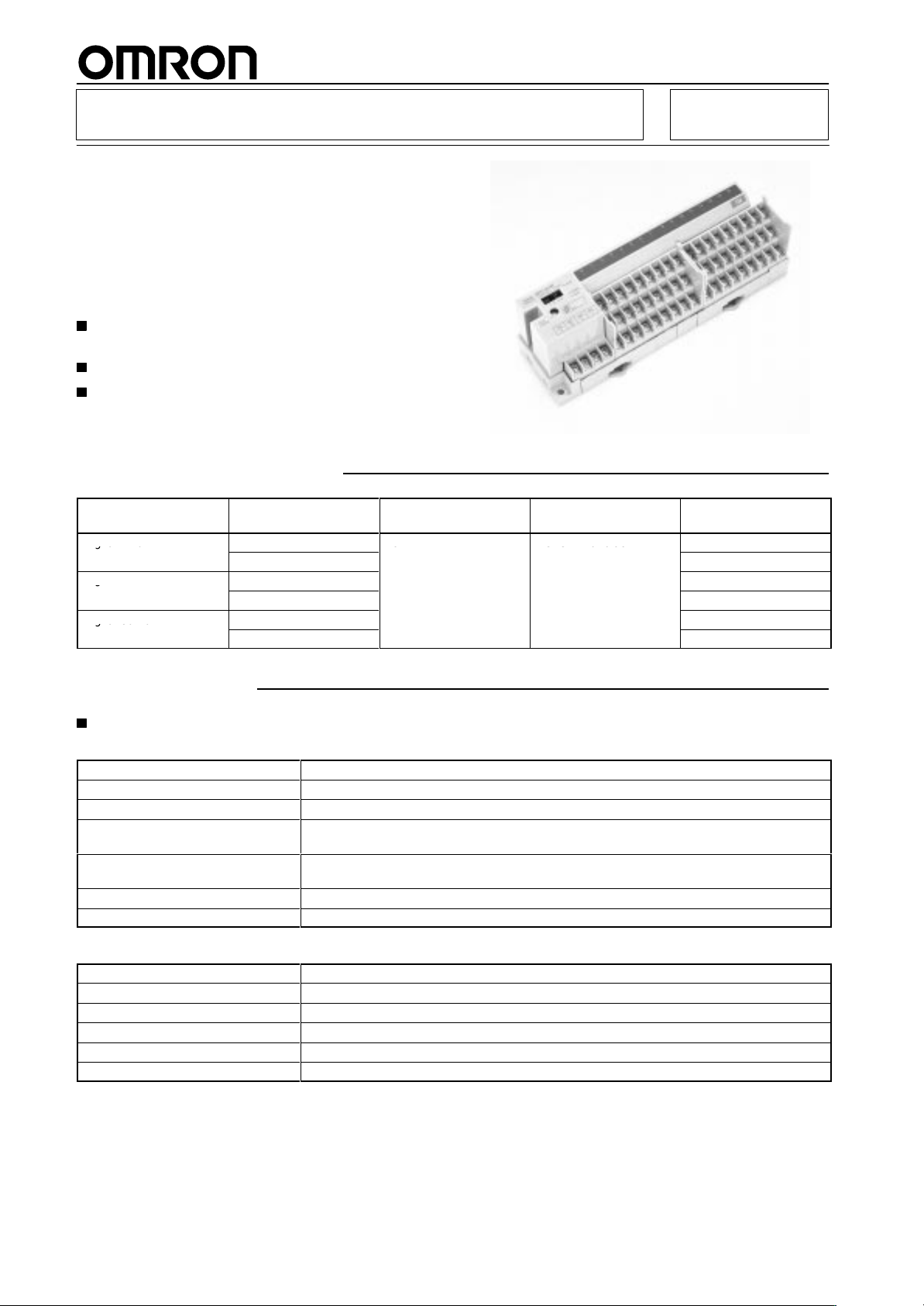
Terminal Arrangement and I/O Device Connection Example (PNP Models)
Note: The
Input
SRT1-ID04
connections examples shown are for PNP models.
SRT2-ID08
SRT2-ID16
Commu-
Commu-
nications
nications
path
power
supply
Output
SRT1-OD04
Commu-
Commu-
nications
nications
path
power
supply
30
I/O
power
supply
Photoelectric sensor or
proximity sensor (threewired sensor with a builtin-amplifier)
I/O
power
supply
Black
Brown
Solenoid, valve Solenoid
Blue
Blue
Brown
Limit switch
(two-wired
sensor)
Communications
path
SRT2-OD08
Communications
path
Communications
power
supply
I/O
power
supply
Photoelectric sensor or
proximity sensor (threewired sensor with a builtin-amplifier)
Communications
power
supply
I/O
power
supply
Brown
Black
Blue
Brown
Limit switch
(two-wired
sensor)
Valve
Blue
Communications
path
SRT2-OD16
Commu-
Commu-
nications
nications
path
power
supply
I/O
Communica-
power
tions
supply
power
supply
Photoelectric sensor or
proximity sensor (threewired sensor with a builtin-amplifier)
I/O
power
supply
Black
Brown
Solenoid
Blue
Brown
Valve
Blue
Limit switch
(two-wired
sensor)
Page 22
SRTj-ID/OD
External Connections (PNP Models)
Input
Three-wired Sensors
SRT1-ID04-1 with NPN Output
SRTj-ID/OD
SRT2-ID08-1 and SRT2-ID16-1 with NPN Output
Black
Brown
Sensor 1
Blue
Black
Brown
Sensor 2
Blue
Brown
Sensor
Black
Blue
1
Black
Brown
Sensor 2
Blue
Two-wired Sensors
SRT1-ID04-1
Brown
Sensor 1
Blue
Brown
Sensor 2
SRT2-ID08-1
Blue
and SRT2-ID16-1
Brown
Sensor 1
Blue
Brown
Sensor 2
Blue
Output
SRT1-OD04-1 SRT2-OD08-1
L 1 L 2
and SRT2-ID16-1
L
1
L 2
Terminal Arrangement and I/O Device Connection Example (PNP Models)
Note: The
Input
SRT1-ID04-1
connections examples shown are for NPN models.
SRT2-ID08-1
SRT2-ID16-1
Commu-
Commu-
I/O
nications
nications
path
power
supply
Photoelectric sensor or proximity sensor (three-wired sensor with a built-in-amplifier)
power
supply
Brown
Output
SRT1-OD04-1
Commu-
Communications
path
nications
power
supply
I/O
power
supply
Solenoid, valve
Precautions
Refer to the
the Unit.
CompoBus/S Operation Manual (W266)
Blue
Black
Brown
Limit switch
(two-wired sensor)
Blue
Commu-
Commu-
nications
nications
path
power
supply
Photoelectric sensor or proximity sensor (three-wired sensor with a built-in-amplifier)
SRT2-OD08-1
Commu-
Commu-
nications
nications
power
path
supply
before
I/O
power
supply
I/O
power
supply
using
Brown
Black
Blue
Blue
Brown
Limit switch
(two-wired sensor)
Communications
path
SRT2-OD16-1
Communications
Solenoid
Valve
path
For general precautions refer to page
I/O
Communications
power
supply
Photoelectric sensor or proximity sensor (three-wired sensor with a built-in-amplifier)
Communications
power
supply
power
supply
I/O
power
supply
Brown
Solenoid
80.
Black
Blue
Blue
Brown
Limit switch
(two-wired sensor)
Valve
31
Page 23
Remote I/O Terminal
ga u
6
3e aboc
g
gaou u
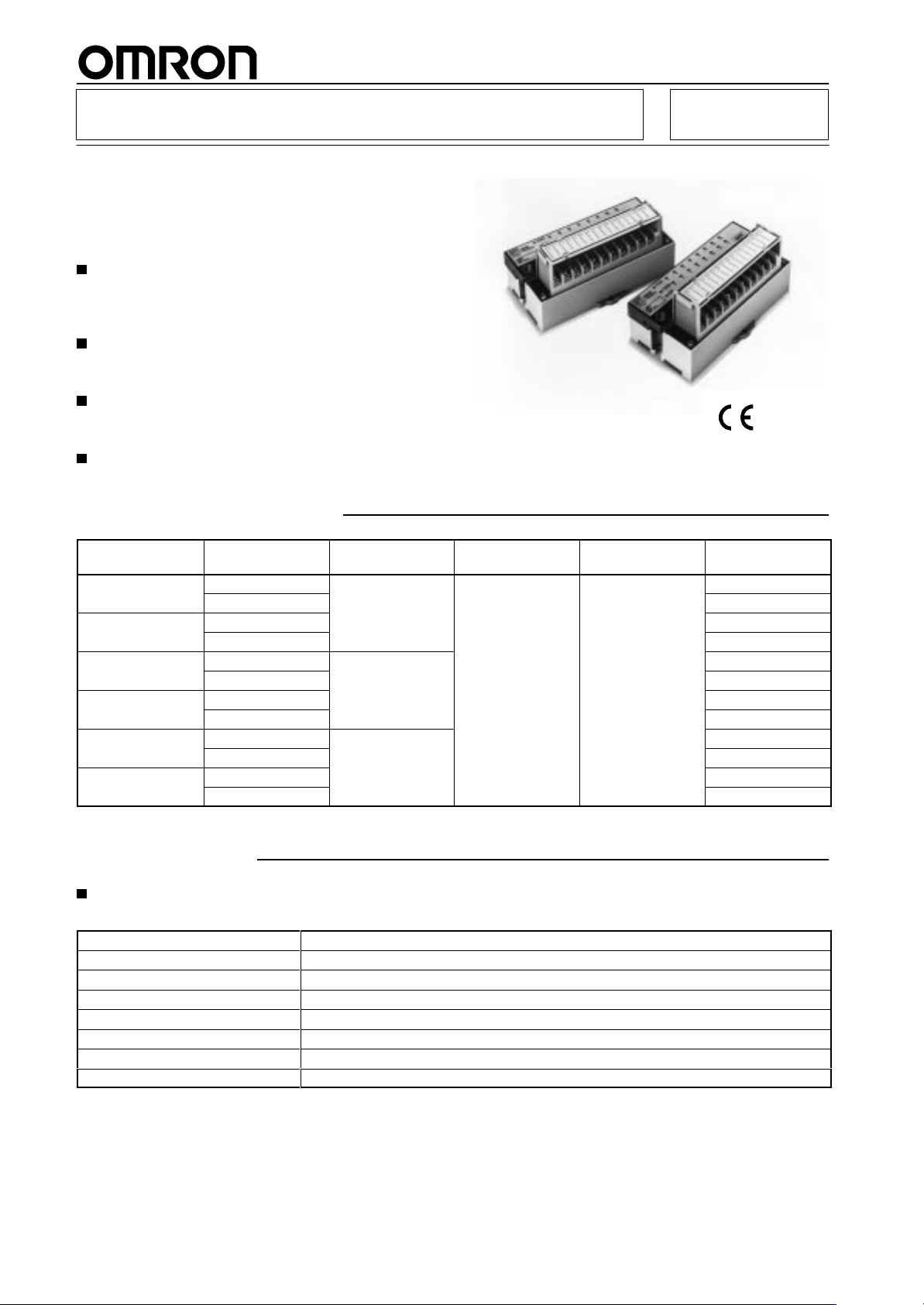
Models with 3-tier Terminals (16 Points)
are Added to the Remote I/O Terminal
Series.
Six Models are Available Depending on
the NPN or PNP Configuration, Input
Points, I/O Points, or Output Points.
SRT1-jD16T(-1)
Incorporates
easy-to-wire terminals each connect
ing to a single wire.
Reduces designing and wiring effort.
Incorporates a removable circuit block of cassette
construction.
Ordering Information
I/O
classification
Digital input
Digital I/O
Digital output
Internal I/O circuit
common
NPN (+ common)
PNP (– common)
NPN (+ common)
PNP (– common)
NPN (– common)
PNP (+ common)
16
Specifications
Ratings
Inputs
Input
current
ON delay time 1.5 ms max.
OFF delay time
ON voltage
OFF voltage
OFF current
Insulation method
6 mA max./point at 24 V and 3 mA min./point at 17 V
1.5 ms max.
NPN: 15 VDC min. between V terminals and each input terminal
PNP: 15 VDC min. between G terminals and each input terminal
NPN: 5 VDC max. between V terminals and each input terminal
PNP: 5 VDC max. between G terminals and each input terminal
1 mA max.
Photocoupler
-
I/O points
I/O connection method
M3 terminal block
Model
SRT1-ID16T
SRT1-ID16T-1
SRT1-MD16T
SRT1-MD16T-1
SRT1-OD16T
SRT1-OD16T-1
Outputs
Rated output current
Residual voltage
ON delay time 0.5 ms max.
OFF delay time
Leakage current
Insulation method
32
0.5 A max./point
1.2 V max.
1.0 ms max.
0.1 mA max.
Photocoupler
Page 24
SRT1-jD16T(-1)
Characteristics
Communications
voltage
I/O power supply voltage
I/O power supply current
Current consumption (see note)
Connection method
Dielectric strength
Noise immunity
V
ibration resistance
Shock resistance
Mounting strength
T
erminal strength
Screw tightening torque
Ambient temperature
Ambient humidity
Weight
Note: The
nected
power supply
above current consumption is the value with all points turned ON excluding the current consumption of the external sensor con
to the input Remote T
SRT1-jD16T(-1)
14 to 26.4 VDC
24 VDC
4 A max./common
50 mA max. at 24 VDC
Multi-drop method and T
Secondary branches cannot be connected to T
500 V
Conforms to IEC61000-4-4, 2 kV (power lines)
10 to 150 Hz, 1.0-mm double amplitude or 70 m/s
200 m/s
No damage with 100 N pull load applied in all directions.
No damage with 100 N pull load applied
0.3 to 0.5 N S m
Operating: –10°
Storage: –25°
Operating:
300 g max.
erminal and the current consumption of the load connected to the output Remote T
+10%
/
–15%
-branch method
AC between insulated circuits
2
C to 55
°C
C to 65
°C
25% to 85% (with no condensation)
-branch lines.
2
erminal.
-
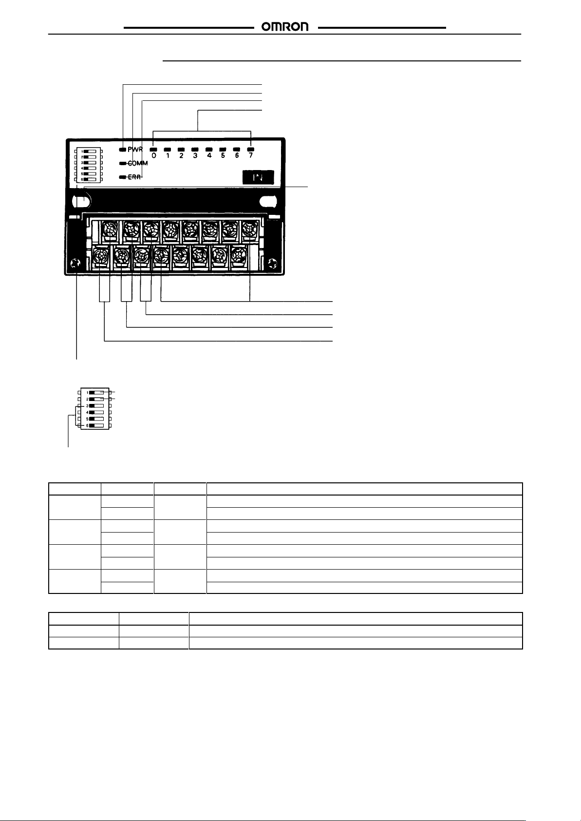
Nomenclature
ERR Indicator: Indicates communications errors.
COMM Indicator: ON while the Unit is in data communication.
Power Indicator
HOLD/CLR DIP Switch
The DIP switch is on the
left-hand side under the cover
on the upper part of the Remote
I/O T
erminal.
Holding or clearing output when a
communications error occurs.
Address Setting Switch
Set the rotary switch to the node
address by referring to the
following table.
Address Setting Switch
Node
address
0 0
1 1
2 2
3 3
4 4
5 5
6 6
7 7
Setting (Hex)
CompoBus/S Internal Power Supply
Terminals (BS+ and BS–)
CompoBus/S Communications Cable
Terminals (BDH and BDL)
Node address
8 8
9 9
10 A
11 B
12 C
13 D
14 E
15 F
I/O Indicators
M4 Mounting Screw
Terminal Cover
The Unit stops operating with the
cover opened.
I/O and I/O Device Power Supply Terminals 8 to 15
These terminals will be used as output terminals 0
through 7 if the connected device handles both input
and output signals.
I/O and I/O Device Power Supply Terminals 0 to 7
These terminals will be used as input terminals if the
connected device handles both input and output
signals.
I/O Power Supply Terminals
Connect 24-VDC I/O power supply
Fixture Track
Used for DIN track mounting.
Setting (Hex)
33
Page 25
SRT1-jD16T(-1)
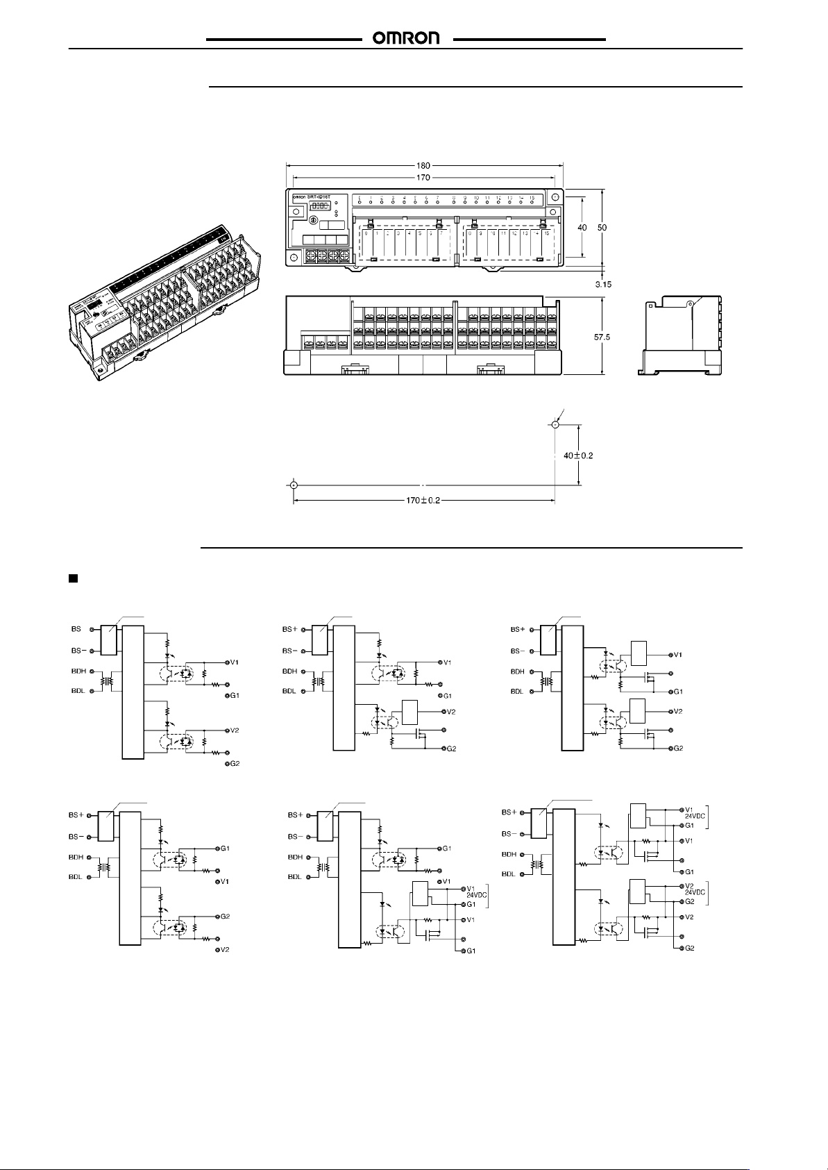
Dimensions
Note:
All units are in millimeters unless otherwise indicated.
SRT1-ID16T (-1)
SRT1-MD16T (-1)
SRT1-OD16T (-1)
SRT1-jD16T(-1)
Two, 4.2 dia. or M4
Two, 4.2 dia. or M4
Mounting Holes
Installation
Internal Circuit Configuration
SRT1-ID16T SRT1-MD16T
SRT1-ID16T-1 SRT1-MD16T-1
DC-DC converter
(isolated type)
Photocoupler
Internal circuit
Photocoupler
DC-DC converter
(isolated type)
Photocoupler
Internal circuit
Photocoupler
Inputs
(0 to 7)
Inputs
(8 to 15)
Inputs
(0 to 7)
Inputs
(8 to 15)
DC-DC converter
(isolated type)
Photocoupler
Internal circuit
Photocoupler
DC-DC converter
(isolated type)
Photocoupler
Internal circuit
Photocoupler
Voltage
drop
Voltage
drop
Inputs
(0 to 7)
Inputs
(0 to 7)
Inputs
(0 to 7)
SRT1-OD16T
I/O
power
supply
Outputs
(0 to 7)
SRT1-OD16T-1
Internal circuit
DC-DC converter
(isolated type)
Photocoupler
Internal circuit
Photocoupler
DC-DC converter
(isolated type)
Photocoupler
Photocoupler
Voltage
Voltage
drop
Voltage
Voltage
drop
drop
drop
Inputs
(0 to 7)
Inputs
(8 to 15)
Outputs
(0 to 7)
Outputs
(8 to 15)
I/O
power
supply
I/O
power
supply
34
Page 26

SRT1-jD16T(-1)
External Connections
SRT1-jD16T(-1)
Input (NPN Models)
SRT1-ID16T
SRT1-MD16T
Blue (Black)
Brown (White)
Two-wired
sensor
Three-wired sensor
Black (White)
Brown (Red)
Blue (Black)
Output (NPN Models)
SRT1-OD16T
SRT1-MD16T
Solenoid, valve, etc.
Input (PNP Models)
SRT1-ID16T-1
SRT1-MD16T-1
Blue (Red)
Black (Black)
Brown (White)
Three-wired sensor
Output (PNP Models)
SRT1-OD16T-1
SRT1-MD16T-1
Solenoid, valve, etc.
35
Page 27

Relay-mounted Remote Terminal
oe OS
Ultra-miniature 8-point and 16-point
Relay-mounted Terminals
Ultra-compact
(8-point models: 101 x 51 x 51 mm (W x H x D);
16-point models: 156 x 51 x 51 mm (W x H x D))
Power MOS FET Relay and Relay models.
DIN track mounting and screw mounting are
available.
Ordering Information
SRTj-R
RC
Classification I/O
Relay output
Power MOS FET
relay output
Note:
For details about connections to the Master Unit, refer to page
8 points
16 points
8 points
16 points
points
Rated voltage
24 VDC 24 VDC SRT1-ROC08 G6D-1A
Specifications
Ratings
Relay Output
Item SRT1-ROC08, SRT2-ROC16
Applicable relay
Rated load
Rated carry current
Max. contact voltage
Max. contact current
Max. switching capacity
Min. permissible load (see note 2)
Life expectancy
Note: 1.
The maximum permissible current of COM0 to COM7 is 3 A.
2. This
value fulfills the P reference value of opening/closing at a rate of 120 times per min (ambient operating environment and deter
mination
criteria according to JIS C5442).
Power MOS FET Relay Output
Item SRT1-ROF08, SRT2-ROF16
Applicable relay
Load voltage
Load current
Inrush current
G6D-1A (one for each output point)
3 A at 250 V
3 A (see note 1)
250 V
AC, 30 VDC
3 A
730 V
A (AC), 90 W (DC)
10 mA at 5 VDC
Electrical:
Mechanical:
G3DZ-2R6PL (one for each output point)
3 to 264 V
100 µA to 0.3 A
6 A (10 ms)
AC, 3 to 125 VDC
Relay coil rating
10.
AC, 3 A at 30 VDC (resistive load)
100,000 operations min. (rated load, at 1,800 operations/h)
20,000,000 operations min. (at 18,000 operations/h)
Model
SRT2-ROC16
SRT1-ROF08 G3DZ-2R6PL
SRT2-ROF16
Applicable relay
-
36
Page 28

SRTj-R
SRTj-R
Characteristics
Power
supply voltage
Current consumption (see note)
Connection method
Connecting Units
Dielectric strength
Noise immunity
V
ibration resistance
Shock resistance
Mounting strength
T
erminal strength
Screw tightening torque
Ambient temperature
Ambient humidity
Weight
Approved standards
Note: The above current consumption is a value with all the points turned ON including the current consumption of the G6D coil for the
Remote
Output T
erminal.
24 VDC
350 mA max. at 24 VDC
Multi-drop method and T
Secondary branches cannot be connected to T
8-point Units: 16 per Master
16-point Units:
2,000 V
between communication terminals, and between contacts of dif
500 V
between communication terminals, and between all power supply terminals and
communications terminals
Conforms to IEC61000-4-4, 2 kV (power lines)
10 to 55 Hz, 0.75-mm double amplitude
Malfunction:
Destruction:
No damage when 50 N pull load was applied for 10 s in all directions
No damage when 50 N pull load was applied for 10 s
0.6 to 1.18 N S m
Operating: 0°
Storage: –20°
Operating:
8-point models: 145 g max., 16-point models: 240 g max.
UL 508, CSA C22.2 No. 14
+10%
/
–15%
-branch method
8 per Master
AC for 1 min (1-mA sensing current) between all output terminals and power supply
AC for 1 min (1-mA sensing current) between all output terminals and power supply
2
100 m/s
2
300 m/s
C to 55°C (with no icing or condensation)
C to 65°C (with no icing or condensation)
35% to 85%
-branch lines.
ferent polarities
,
,
37
Page 29

SRTj-R
Nomenclature
SRTj-R
SRT2-ROC16
SRT2-ROF16
Note: Always
SRT1-ROC08
SRT1-ROF08
Mounting
turn of
Holes
DIP Switch
Used for node number setting and holding or
clearing outputs for communications error
f the Unit before changing DIP switch settings.
Mounting
Holes
PWR
COMM
ERR
0
to 15
Indicators
Indicator Display Color Meaning
PWR Lit Green The communications power supply is ON.
Not lit The communications power supply is OFF.
COMM Lit Yellow Normal communications
Not lit A communications error has occurred or
ERR Lit Red A communications error has occurred.
Not lit Normal communications or the Unit is in
0 to 15
(see
note)
Note: The
.
Lit Yellow The corresponding I/O signal is ON.
Not lit The corresponding I/O signal is OFF.
SR
T1-ROj
Mounting
Output Terminals
I/O Power Supply Terminals
Connect 24-VDC power supply
Communications Power Supply Terminals
Connect 24-VDC power supply.
CompoBus/S Terminals
Connect the CompoBus/S communications cable.
Output HOLD/CLEAR setting (Output model only)
Baud rate setting
Node address setting
the Unit is in standby status.
standby status.
08 does not have indicators 8 to 15.
Holes
DIP Switch
Used for node number setting and holding or clearing outputs for communications error.
Mounting
Output Terminals
I/O Power Supply Terminals
Connect 24-VDC power supply
Communications Power Supply Terminals
Connect 24-VDC power supply.
CompoBus/S Terminals
Connect the CompoBus/S communications cable.
Holes
38
Page 30

SRTj-R
Output HOLD/CLEAR Mode
Mode Pin
HOLD ON
CLEAR OFF
Note: 1. Pin 1 is factory-set to OFF.
2.
This function is available to the Output T
Node Number Settings
Node
number
0 OFF OFF OFF OFF
1 OFF OFF OFF ON
2 OFF OFF ON OFF
3 OFF OFF ON ON
4 OFF ON OFF OFF
5 OFF ON OFF ON
6 OFF ON ON OFF
7 OFF ON ON ON
8 ON OFF OFF OFF
9 ON OFF OFF ON
10 ON OFF ON OFF
11 ON OFF ON ON
12 ON ON OFF OFF
13 ON ON OFF ON
14 ON ON ON OFF
15 ON ON ON ON
Note: 1.
The node number is factory-set to 0.
2.
For node number setting, refer to the
1
Output status is maintained when a communications error occurs.
Output status is cleared when a communications error occurs.
erminal only
Pin 3 Pin 4 Pin 5 Pin 6
8 4 2 1
CompoBus/S Operation Manual (W266).
.
Setting
SRTj-R
39
Page 31

SRTj-R
Dimensions
Note:
All units are in millimeters unless otherwise indicated.
SRTj-R
SRT1-ROC08
SRT1-ROF08
SRT2-ROC16
SRT2-ROF16
Mounting Holes
100
80
50
40
Sixteen,
M3
Two, 4.2 dia. or M4
50
50
Mounting Holes
155
135
50
40
Thirty two, M3
Two, 4.2 dia. or M4
50
50
40
Page 32

SRTj-R
Installation
Internal Circuit Configuration
SRT1-ROC08
SRT2-ROC16
Relay driver
circuit
(See
note)
*
Later
blocks
SRTj-R
Internal
circuit
Relay
driver
circuit
Relay driver
circuit
Relay driver
circuit
Note: The G3DZ-2R6PL Power MOS FET Relay is inserted into
this
portion of the SR
T1-ROF08 and SR
T2-ROF16.
External Connections
Load
Lamp
Lamp
Lamp
Lamp
power
supply
Terminal Arrangement and I/O Device Connection Example
Output
SRT2-ROC16
SRT2-ROF16
*(see
note 2)
Note: 1. Dotted
Precautions
Refer to the
the Unit.
Refer to page 80 for details.
CompoBus/S Operation Manual (W266)
24-VDC
power supply
Load
Communications
path
Load
Load
Load
Power
Power
supply
supply
Power
Power
supply
supply
Load
Load
Load
Load
Load
Load
Load
Load
Power
supply
Power
supply
Power
Power
supply
supply
Load
Load
Load
Load
lines indicate internal connections.
SRT1-ROC08 and SR
T1-ROF08 have the 0 to 7 and COM0 to COM3 terminals only
2. The above is a connection example of the SRT2-ROC16 with G6D Relays mounted.
G3DZ
Power MOS FET Relays are mounted to the SR
T1-ROF08 and SR
T2-ROF16.
before using
.
41
Page 33

Connector Terminal
g
Se so co ec o
gaou u
ga u
6
co ec o
gaou u
Compact Connector Terminals Save
Wiring Effort and Enable Long-distance
Communications
Long-distance or high-speed communications
mode is selectable.
Incorporates I/O connectors making it possible to
minimize the size.
I/O connectors save wiring effort.
Flexible DIN track mounting is possible through a
DIN track attachment.
Eight-point sensor connector models and 16-point
MIL connector models are the same size.
Features
Vertical
or horizontal DIN track mounting according to the available space is possible.
Saves space and easily connects to other devices without wiring ef
Standard mounting
(Sensor connector model)
Communications and
power supply connector
Mounting with DIN
track attachment
DIN track
fort.
Standard mounting
(MIL connector model)
SRT2-VID/VOD
G7TC
Sensor connector
Indicators
Setting switch
DIN track mounting hook
Ordering Information
I/O
classification
Digital input
Digital output
Digital input
Digital output
Mounting hook A
Mounting hook B
Note:
For details about connecting the SR
Internal I/O circuit
common
NPN (+ common)
PNP (– common)
NPN (– common)
PNP (+ common)
NPN (+ common)
PNP (– common)
NPN (– common)
PNP (+ common)
T2-VID or SR
MIL connector
I/O points
8
16
T2-VOD to the Master Unit, refer to page
I/O connection method
Sensor connector
MIL connector
Model
SRT2-VID08S
SRT2-VID08S-1
SRT2-VOD08S
SRT2-VOD08S-1
SRT2-VID16ML
SRT2-VID16ML-1
SRT2-VOD16ML
SRT2-VOD16ML-1
SRT2-ATT01
SRT2-ATT02
10.
42
Page 34

SRT2-VID/VOD
Specifications
Ratings
Inputs
Item SRT2-VID08S
Input
current
ON delay time 1.5 ms max.
OFF delay time
ON voltage
OFF voltage
OFF current
Insulation method
Maximum number of inputs
Number of circuits
Outputs
Item SRT2-VID08S
Rated output current
Residual voltage
ON delay time 0.5 ms max.
OFF delay time
Leakage current
Insulation method
Number of circuits
Note:
When using V/G terminals in an MIL connector
Characteristics
Communications
voltage
I/O power supply voltage
I/O power supply current
Current consumption (see note)
Noise immunity
V
ibration resistance
Shock resistance
Dielectric strength
Ambient temperature
Ambient humidity
Mounting strength
T
erminal strength
Screw tightening torque
Node address setting
Weight
Note: The
nected
power supply
above current consumption is the value with all points turned ON excluding the current consumption of the external sensor con
to the input Remote T
6 mA max./point at 24 V, 3 mA max./point at 17 V
1.5 ms max.
15 VDC min. (Between each input terminal and V
5 VDC max. (Between each input terminal and V
1 mA max.
Photocoupler
8 12
8 points/common, 1 circuit 16 points/common, 1 circuit
0.3 A/point
1.2 V max.
1.5 ms max.
0.1 mA max.
Photocoupler
8 points/common, 1 circuit 16 points/common, 1 circuit
14 to 26.4 VDC
20.4 to 26.4 VDC (24 VDC
Sensor connector: 2.4 A max., MIL connector: 2.0 A max.
50 mA max. at 24 VDC
Conforms to IEC61000-4-4, 2 kV (power lines)
10 to 150 Hz, 1.0-mm double amplitude or 70 m/s2 (50 m/s2 for SR
200 m/s
500 V
AC (between insulated circuits)
Operating: –10°
Storage: –25°
Operating:
Storage:
No damage when 100 N pull load was applied in all directions (40 N load for SR
No damage when the following loads were applied:
Communications connector: 100 N
Sensor connector: 40 N
MIL connector: 100 N
Communications connector: 0.25 N S m
Settings made at DIP switch (set before supplying power for Slave communications)
Approx. 75 g max.
erminal and the current consumption of the load connected to the output Remote T
SRT2-VID/VOD
SRT2-VID08S-1
: NPN. Between each input and G: PNP
: NPN. Between each input and G: PNP
SRT2-VID08S-1
0.3 A/point (2-A common) (See note.)
, ensure that the current per terminal for the V/G terminals does not exceed 1 A.
+10%
/
)
–15%
2
C to 55°C (with no icing or condensation)
C to 65
°C
25% to 85% (with no condensation)
25% to 85%
SRT2-VID16ML
SRT2-VID16ML-1
SRT2-VID16ML
SRT2-VID16ML-1
T2-ATT02)
T2-ATT02)
erminal.
.)
.)
-
43
Page 35

SRT2-VID/VOD
Nomenclature
SRT2-VID/VOD
SRT2-VID08S/SRT2-VID08S-1
SRT2-VOD08S/SRT2-VOD08S-1
(Sensor Connector Models)
Communications
Connectors
I/O Connectors
SRT2-VID16ML/SRT2-VID16ML-1
SRT2-VOD16ML/SRT2-VOD16ML-1
(MIL Connector Models)
Communications
Connectors
I/O Connectors
Indicators
DIP Switch
Indicators
Indicator DisplayColor Meaning
PWR LitGreen The communications power
COMM LitYellow Normal communications
ERR LitRed A communications error
0 to 7
(for
8-point
I/O)
0 to 15
(for
16-point
I/O)
Name
Power
Communications
Communications
error
Input
(output)
supply is ON.
Not lit The communications power
supply is OFF.
Not lit A communications error has
occurred or the Unit is in
standby status.
has occurred.
Not lit Normal communications or
the Unit is in standby status.
LitYellow The corresponding I/O
signal is ON.
Not lit The corresponding I/O
signal is OFF.
Output HOLD/CLEAR Mode Setting
Output HOLD/CLEAR Mode
SW8 (HOLD) Setting
Output status is cleared.OFF
Output status is maintained.ON
Communications Mode Setting
Communications
SW7 (HOLD) Setting
Mode
High-speed communications modeOFF
Long-distance communications modeON
Reserved for System Use (Always OFF)
Node Address Setting
Node
Number Settings
Node number Pin 4 Pin 3 Pin 2 Pin 1
8421
0 OFF OFF OFF OFF
1 OFF OFF OFF ON
2 OFF OFF ON OFF
3 OFF OFF ON ON
4 OFF ON OFF OFF
5 OFF ON OFF ON
6 OFF ON ON OFF
7 OFF ON ON ON
8 ON OFF OFF OFF
9 ON OFF OFF ON
10 ON OFF ON OFF
11 ON OFF ON ON
12 ON ON OFF OFF
13 ON ON OFF OFF
14 ON ON ON OFF
15 ON ON ON ON
Note: Be sure to perform settings with the Slave
power supply OFF.
44
Page 36

SRT2-VID/VOD
Dimensions
Note:
All units are in millimeters unless otherwise indicated.
SRT2-VID08S
SRT2-VID08S-1
SRT2-VOD08S
SRT2-VOD08S-1
SRT2-VID16ML
SRT2-VID16ML-1
SRT2-VOD16ML
SRT2-VOD16ML-1
SRT2-VID/VOD
SRT2-ATT01
SRT2-ATT02
Dimensions when Unit is mounted.
45
Page 37

SRT2-VID/VOD
Installation
Internal Circuit Configuration
SRT2-VID08S SRT2-VID08S-1
SRT2-VID/VOD
Photocoupler
Photocoupler
Internal circuit
SRT2-VOD08S
Photocoupler
Photocoupler
Internal circuit
Voltage
drop
SRT2-VOD08S-1
SRT2-VID16ML SRT2-VID16ML-1
Photocoupler
Photocoupler
Internal circuit
Photocoupler
Photocoupler
Internal circuit
Voltage
drop
Photocoupler
Photocoupler
Internal circuit
SRT2-VOD16ML SRT2-VOD16ML-1
Photocoupler
Voltage
drop
Photocoupler
Internal circuit
Photocoupler
Photocoupler
Internal circuit
Photocoupler
Internal circuit
Photocoupler
Voltage
drop
46
Page 38

SRT2-VID/VOD
Terminal Arrangement and I/O Device Connection Examples
SRT2-VID08S SRT2-VID08S-1
SRT2-VOD08S
SRT2-VID/VOD
SRT2-VOD08S-1
CompoBus/S
communications
Sensor
Brown
(Red)
Black (White)
Blue (Black)
Three-wired
Sensor
Brown
(White)
Blue (Black)
Two-wired
CompoBus/S
communications
power supply
sensor
sensor
Pin numbers
I/O power
supply
CompoBus/S
communications
Sensor
Brown
(Red)
Black (White)
Blue (Black)
Three-wired sensor
Sensor
Brown (White)
Blue (Black)
Two-wired sensor
CompoBus/S
communications
power supply
SRT2-VID16ML SRT2-VID16ML-1
CompoBus/S
communications
Sensor
Brown (Red)
Black (White)
Blue (Black)
Three-wired sensor
Sensor
Brown (White)
Blue (Black)
Two-wired sensor
CompoBus/S
communications
power supply
I/O power
supply
Pin numbers
CompoBus/S
communications
Sensor
Brown (Red)
Black (White)
Blue (Black)
Three-wired sensor
Sensor
Brown (White)
Blue (Black)
Two-wired sensor
CompoBus/S
communications
power supply
Pin numbers
Pin numbers
I/O power
supply
I/O power
supply
CompoBus/S
communications
Solenoid etc.
Output
device
Output
device
V
alve etc.
CompoBus/S
communications
power supply
SRT2-VOD16ML
CompoBus/S
communications
Solenoid etc.
V
Output
device
Output
device
alve etc.
CompoBus/S
communications
power supply
Pin numbers
Pin numbers
I/O power
supply
I/O power
supply
CompoBus/S
communications
Solenoid etc.
Output
device
Output
device
V
alve etc.
CompoBus/S
communications
power supply
SRT2-VOD16ML-1
CompoBus/S
communications
Solenoid etc.
Output
device
Output
device
V
alve etc.
CompoBus/S
communications
power supply
Pin numbers
Pin numbers
I/O power
supply
I/O power
supply
Note: 1. V
2.
terminals and G terminals are respectively connected internally
When
supplying power for I/O from communications connectors, power can be supplied to the sensor output devices from V and G
.
terminals.
When using an inductive load (solenoid, valve etc.), either use one with an internal reverse electromotive force absorption diode or
attach
a diode externally
.
47
Page 39

SRT2-VID/VOD
Precautions
Refer to the
the Unit.
Refer to page
Communications Connector Pin Arrangement
The
following solderless terminals are recommended.
•
Manufacturer: W
CompoBus/S Operation Manual (W266)
80 for common precautions.
24-VDC
communications
power supply
CompoBus/S communications
24-VDC I/O
power supply
eidmuller
Sleeve (Part No. 046290)
Solderless
terminal
Two-wire insertion (Part No. 901851)
Cable
before
using
SRT2-VID/VOD
Note: The XS8A-0441 or XS8A-0442 Connector is not provided
with
the SRT-VID or SR
nector
separately
Calculate the cable conductor size as follows.
The following information is given on each sensor cable:
Cable dia. (Number of conductors/Conductor dia.)
Conductor size (mm2) =
(Conductor dia./2)2 x π
Example: E3S-A
4 dia. (18/0.12)
Conductor size (mm2) = (0.12/2)2 x 3.14 x 18 ] 0.20
The conductor size is 0.2 mm2. Therefore, use the XS8A-0442.
MIL Connector Pin Arrangement
SRT2-VID16ML/VID16ML-1
Function
IN0
IN1
IN2
IN3
IN4
IN5
IN6
IN7
G
V
Pin No.
20
18
16
14
12
10
8
6
4
2
T2-VOD. Place
an order for the con
.
x Number of conductors
Function
Pin No.
19
17
15
13
11
9
7
5
3
1
IN8
IN9
IN10
IN11
IN12
IN13
IN14
IN15
G
V
-
Solderless
terminal
The
following product is a dedicated tool.
•
Manufacturer: W
eidmuller
Cable
PZ1.5 Crimper (Part No. 900599)
Sensor Connector Pin Arrangement
SRT2-VID08S/VID08S-1
SRT2-VOD08S/VOD08S-1
XS8A-0441
XS8A-0442
Model Cable
0.3 to 0.5 mm
0.14 to 0.2 mm
conductor size
2
SRT2-VOD16ML/VOD16ML-1
Function Pin No.
OUT0
OUT1
OUT2
OUT3
OUT4
OUT5
OUT6
OUT7
G
V
20
18
16
14
12
10
8
6
4
2
Function
19
17
15
13
11
9
7
5
3
1
Pin No.
OUT8
OUT9
OUT10
OUT11
OUT12
OUT13
OUT14
OUT15
G
V
Note: 1. No cable connector is provided. Order the connector
separately.
• Applicable
Connector
XG4M-2030-T
•
Applicable Connector Cables
G79-O50C
G79-O25C
G79-I50C
G79-I25C
2. Refer to the following table for ordering information on
the
applicable Cables.
2
48
Page 40

SRT2-VID/VOD
G7TC IA16 5
G7TC
Applicable Cables
Connectable
I/O Block G7TC-OC16
Connector-T
Digital Display Unit
I/O Block G7TC-ID16
erminal Conversion Unit
product
G7TC-OC08
G7TC-ID16-5
G7TC-IA16-5
G7VC Series
G70A Series
G70D Series
XW2B Series
M7F
-IA16
G7TC-OC16-1
Model
↔
↔
SRT2-VID/VOD
Applicable Cable
G79-O50C (L = 500 mm)
G79-O25C (L = 250 mm)
G79-I50C (L = 500 mm)
G79-I25C (L = 250 mm)
49
Page 41

Sensor Terminal
Connector Connection Models that
Allows Easy Connection to Sensors and
Output Devices
Sensors with easy-to-wire connectors are easily
attached or detached.
Connects to 2-wired sensors.
Remote
with the PC by using output signals of the Sensor
Terminal.
DIN track mounting and screw mounting are
available.
Ordering Information
teaching of the Sensor T
erminal is possible
SRT1-jD08S
Classification Internal
For input
For I/O NPN (– common)
For output
NPN (– common)
NPN (– common)
I/O circuit common
Specifications
Ratings
Input
Item SRT1-ID08S/-ND08S
Input
current
ON delay time
OFF delay time
ON voltage
OFF voltage
OFF current
Insulation method
Input indicator
Output
Item SRT1-ND08S SRT1-OD08S
Rated output current
Residual voltage
ON delay time
OFF delay time
Leakage current
Insulation method
Output indicator LED (yellow)
10 mA max./point
1 ms max.
1.5 ms max.
12 VDC min. between each input terminal and VCC, the external sensor power supply
4 VDC max. between each input terminal and VCC, the external sensor power supply
1 mA max.
Photocoupler
LED (yellow)
20 mA/point 30 mA/point
1 V max.
1 ms max.
1.5 ms max.
0.1 mA max.
Photocoupler
I/O points
8 input points
4 input/4 output points
8 output points
0.6 V max.
---
---
Model
SRT1-ID08S
SRT1-ND08S
SRT1-OD08S
50
Page 42

SRT1-jD08S
Characteristics
Communications
voltage (see note 1)
Current consumption (see note 2)
Connection method
Dielectric strength
Noise immunity
V
ibration resistance
Shock resistance
Mounting method
Mounting strength
T
erminal strength
Ambient temperature
Ambient humidity
Weight SR
Note: 1.
2. The
power supply
The communications power supply voltage must be 20.4 to 26.4 VDC if the Unit is connected to 2-wired proximity sensors.
above current consumption is a
to
the Sensor T
erminal.
14 to 26.4 VDC
50 mA max. at 24 VDC
Multi-drop method and T
Secondary branches cannot be connected to T
500 V
Power supply normal:±600 V for 10 minutes with a pulse width of 100 ns to 1
Power supply common:±1,500 V for 10 minutes with a pulse width of 100 ns to 1
10 to 55 Hz, 1.5-mm double amplitude
Malfunction:
Destruction:
M4 screw mounting or 35-mm DIN track mounting
No damage when 50 N pull load was applied for 10 s in all directions (except the DIN track
directions and a pulling force of 10 N
No damage when 50 N pull load was applied for 10 s in all directions
T
ighten each screw to a torque of 0.6 to 1.18 N S m
Operating: 0°
Storage: –20°
Operating:
T1-ID08S/OD08S: 100 g max., SR
value with all the points turned OFF excluding the current consumption of the sensor connected
External Sensor Power Supply
Power
supply voltage 13.5 to 26.4 VDC
Current consumption
500 mA max. in total
-branch method
AC for 1 min (1-mA sensing current between insulated circuits)
2
200 m/s
2
300 m/s
C to 55°C (with no icing or condensation)
C to 65°C (with no icing or condensation)
35% to 85%
T1-ND08S: 80 g max.
-branch lines.
SRT1-jD08S
µs
µs
Nomenclature
SRT1-ID08S
SRT1-ND08S
Mounting Screw Holes
Used when screwing the Unit to
a control panel.
DIP Switch
The DIP switch’
following functions:
Pins 1 to 4: Node number setting
Pin 5: Reserved (Always OFF.)
Pin 6: Hold/clear outputs for com
munications error
Indicators
PWR
COMM
ERR
IN0 to 3
IN0 to 7
OUT0 to 3
CompoBus/S Terminals
Connect the CompoBus/S com
munications cable.
Communications Power
Supply T
Connect the communica
tions power supply
erminals
s pins have the
-
.
CompoBus/S Indicators
Indicate the operating status of the Slave and the status
of communications.
I/O Indicators
Indicate the status of each point.
(Lit when the input or output is ON.)
The SR
T1-ID08S has 8 input indi
cators and the SR
input indicators and 4 output indica
tors.
-
DIN T
rack Mounting Hook
-
Used when mounting the Unit
to a DIN track.
Sensor T
I/O Connectors
Connect the
cables from the
sensors here.
T1-ND08S has 4
erminal
-
-
51
Page 43

SRT1-jD08S
Co u ca o
(
)
0o3
Indicators
Indicator Name Display Color Meaning
PWR Power supply Lit Green
Not lit
COMM Communication Lit Yellow
Not lit
ERR
0 to 3
p
4 inputs/outputs
0 to 7 (8 inputs)
0 to 3
(4 inputs/outputs)
Communication
error
Input Lit Yellow
p
Output Lit Yellow
Lit Red
Not lit
Not lit
Not lit
The communications power supply is ON.
The communications power supply is OFF
Normal communications
A communications error has occurred or the Unit is in standby status.
A communications error has occurred.
Normal communications or the Unit is in standby status.
The corresponding input is ON.
The corresponding input is OFF or the Unit is in standby status.
The corresponding output is ON.
The corresponding output is OFF or the Unit is in standby status.
SRT1-jD08S
.
Switch Setting
All
pins are factory-set to OFF
.
Pin 5 (Reserved)
Always
set pin 5 to OFF
.
Output HOLD/CLEAR Mode (SRT-ND16S)
HOLD Function
Node number
settings
Hold/Clear
outputs for
communications error
Reserved (OFF)
OFF Output
ON
status is cleared when a
communications error occurs.
Output status is maintained when a
communications error occurs.
Node Number Settings
Node
number
0 OFF OFF OFF OFF
1 ON OFF OFF OFF
2 OFF ON OFF OFF
3 ON ON OFF OFF
4 OFF OFF ON OFF
5 ON OFF ON OFF
6 OFF ON ON OFF
7 ON ON ON OFF
8 OFF OFF OFF ON
9 ON OFF OFF ON
10 OFF ON OFF ON
11 ON ON OFF ON
12 OFF OFF ON ON
13 ON OFF ON ON
14 OFF ON ON ON
15 ON ON ON ON
1 2 4 8
52
Page 44
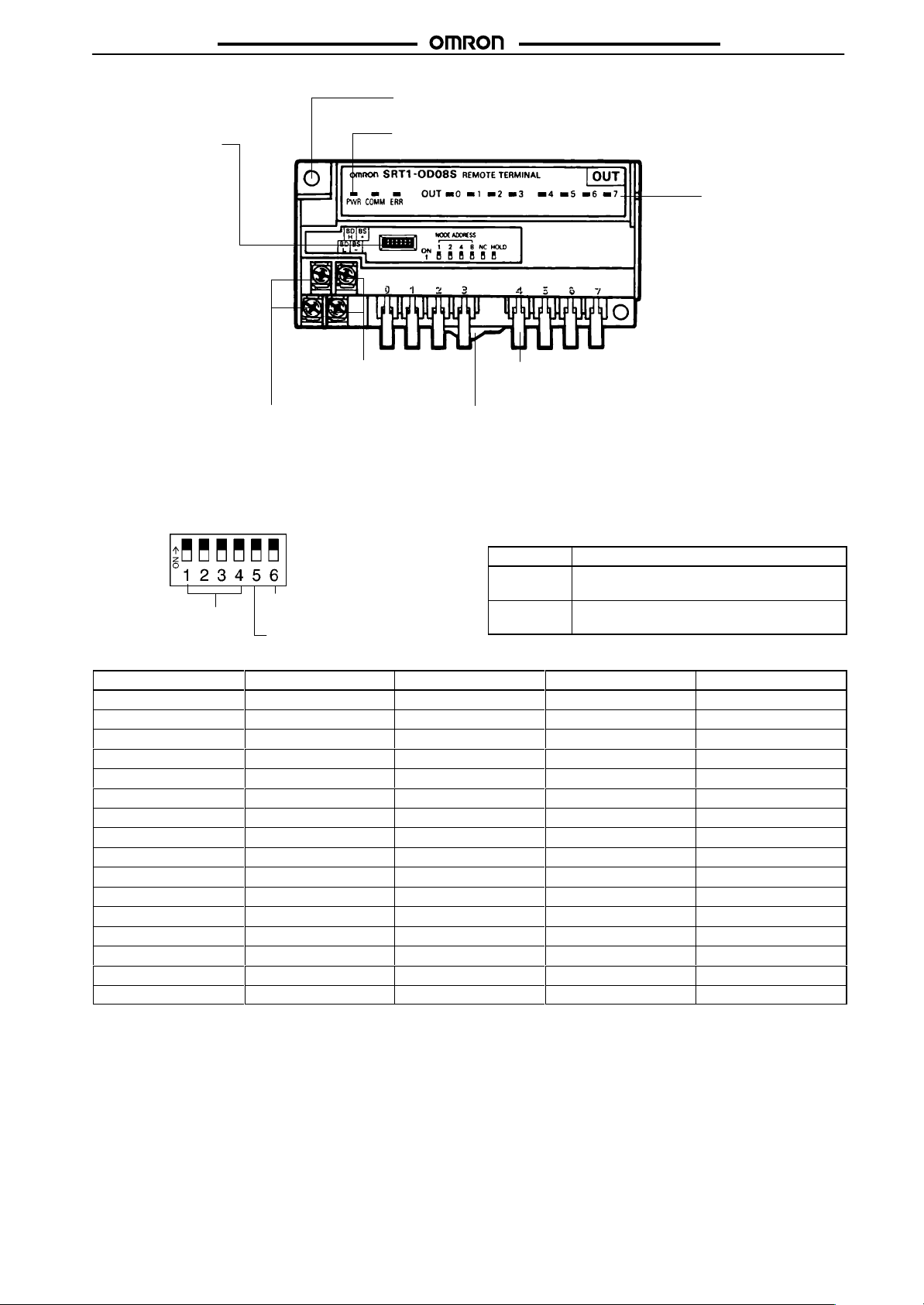
SRT1-jD08S
SRT1-jD08S
SRT1-OD08S
DIP Switch
Communications T
Connect the communica
tions cable.
Switch Setting
All
pins are factory-set to OFF
Communications Power
Supply T
erminals
-
.
erminals
Mounting Screw Holes
Used when screwing the Unit to a control panel.
CompoBus/S Indicators
Indicate the operating status of the Slave and the status of communications.
Output Connectors
Connect the cables from
the output device.
DIN Track
Mounting Hook
Used when mounting the Unit
to a DIN track.
Pin 5 (Reserved)
Always
set pin 5 to OFF
.
Output HOLD/CLEAR Mode (SRT-ND16S)
HOLD Function
Node number
settings
Hold/Clear
outputs for
communications error
Reserved (OFF)
OFF Output
ON
status is cleared when a
communications error occurs.
Output status is maintained when a
communications error occurs.
Node Number Settings
Node
number
0 OFF OFF OFF OFF
1 OFF OFF OFF ON
2 OFF OFF ON OFF
3 OFF OFF ON ON
4 OFF ON OFF OFF
5 OFF ON OFF ON
6 OFF ON ON OFF
7 OFF ON ON ON
8 ON OFF OFF OFF
9 ON OFF OFF ON
10 ON OFF ON OFF
11 ON OFF ON ON
12 ON ON OFF OFF
13 ON ON OFF ON
14 ON ON ON OFF
15 ON ON ON ON
4 3 2 1
Output Indicators
Indicate the output sta
tus of each channel.
-
53
Page 45

SRT1-jD08S
Dimensions
Note:
All units are in millimeters unless otherwise indicated.
SRT1-ID08S
SRT1-jD08S
(75)
100
SRT1-ND08S
50
Cover opening and
closing directions
Mounting Holes
Two, 4.2 dia or M4
Four
, M3
(75)
70 max.
50
Cover opening and
closing directions
54
Four
Mounting Holes
Two, 4.2 dia or M4
, M3
Page 46
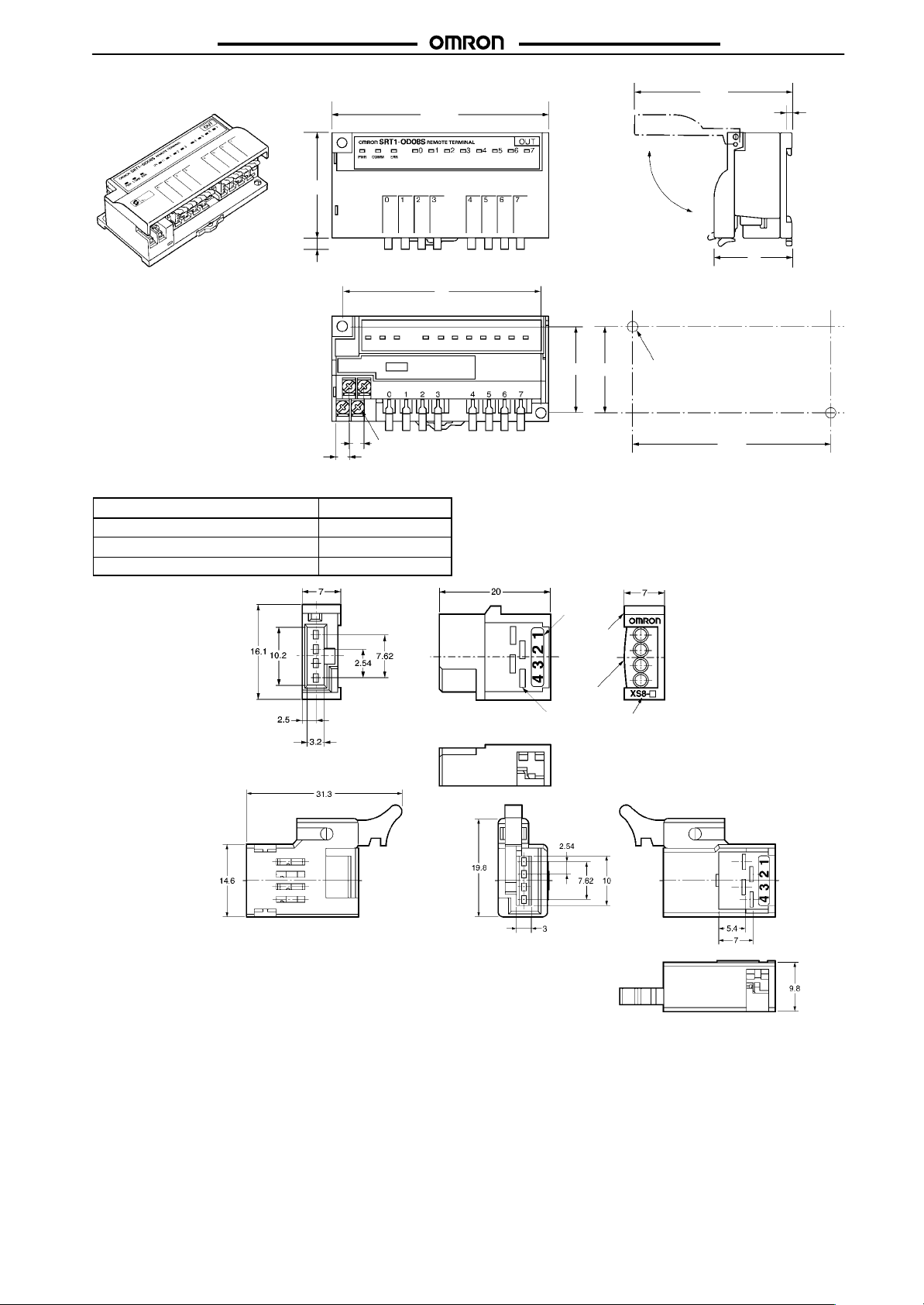
SRT1-jD08S
SRT1-jD08S
SRT1-OD08S
50
4
Cable Connector for SRT1-OD08S
Applicable
0.3 to 0.5
0.14 to 0.2
0.3 to 0.5
conductor size (mm2) Model
XS8A-0441
XS8A-0442
XS8B-0443
(75)
Holes
92
±
2.8
37
0.2
100
Cover opening and
closing directions
92
Mounting
40
40
Four
, M3
7
6
±
0.2
Two, 4.2 dia. or M4
XS8A-044j
(Cable Connector)
XS8B-0443
(Relay Socket )
Calculate
The following information is given on each sensor cable:
Example: E3S-A
The conductor size is 0.2 mm2. Therefore, use the XS8A-0442.
the cable conductor size as explained below
Cable dia. (Number of conductors/Conductor dia.)
Conductor size (mm2) = (Conductor dia./2)2 x π
4 dia. (18/0.12)
Conductor size (mm2) = (0.12/2)2 x 3.14 x 18 ] 0.20
.
Check window
x Number of conductors
Pin number
Plug
connector
Cover
Model number
55
Page 47

SRT1-jD08S
Installation
Internal Circuit Configuration
SRT1-ID08S SRT1-ND08S
Photocoupler
Internal
circuit
SRT1-OD08S
Internal
circuit
Photocoupler
Photocoupler
SRT1-jD08S
Internal
circuit
For one output
External Connections
SRT1-ID08S SRT1-ND08S
Three-wired Sensor Two-wired Sensor Sensor with Teaching Function
Sensor with External Diagnostic function
Sensor with Bank-switching Function
Black
Brown
Sensor
Blue
Brown
Sensor
Blue
Black
Brown
Sensor
Pink
Blue
Three-wired Sensor
Blue
Black
Brown
Sensor
Two-wired Sensor
Blue
Brown
Sensor
56
Page 48

SRT1-jD08S
Terminal Arrangement and I/O Device Connection Example
Input
SRT1-ID08S
SRT1-jD08S
I/O
SRT1-ND08S
CompoBus/S
CompoBus/S
communications
CompoBus/S
CompoBus/S
communications
24 VDC
Communications
power supply
24 VDC
Communications
power supply
CompoBus/S
communications
CompoBus/S
communications
Communications
power supply
Photoelectric Sensor
Proximity Sensor
(3-wired Sensor)
Communications
power supply
Blue
Brown
Proximity Sensor
(2-wired Sensor)
Blue
Orange
Brown
Brown
Photoelectric Sensor
Proximity Sensor
(Sensor with Teaching Function, Sensor with External Diagnostic
function, Sensor with Bank-switching Function)
Brown
Blue
Black
Output
SRT1-OD08S
CompoBus/S
BDL BDH
CompoBus/S
communications
SOURCE
24 VDC
Pin number
–
+
Communications
power supply
Precautions
Refer to the
the Unit.
General Safety Precautions
Installation Environment
Do
not install the Unit in the following places.
•
Places with water
•
Places with rapid temperature changes.
•
Places with high humidity resulting in condensation.
•
Places with intense electric and magnetic fields.
• Places with excessive vibration or shock.
CompoBus/S Operation Manual (W266)
, oil, or chemical sprayed on the Unit.
Solenoid, etc.
before
using
Output connector
Valve, etc.
Wiring
To
prevent inductive noise, do not wire power
lines
along with or near the cables.
Make sure that the polarity of each terminal is correct.
Make sure that the communications path and power line are con-
nected correctly.
Secure
the cables
properly
. Do not pull the cables with strong force,
otherwise the cables may be disconnected from the terminals or
connectors
Do
ent
be
high.
Do
the
of the Unit.
not touch the Unit when the Unit is used in places with high ambi
temperatures because the surface temperature of the Unit may
not use paint thinner to
clean the surface of the Unit, otherwise
surface will be damaged or discolored.
lines or high-tension
-
57
Page 49

SRT1-jD08S
Correct Use
Use
the Unit under its rated conditions.
Mount the Unit with M4 screws or to DIN tracks securely.
Typical Causes of Communications Errors
• The
cables are not connected correctly
•
The node number setting is incorrect.
•
The baud rate setting is incorrect.
• There
is a strong noise source, such as an inverter motor, near
the
Unit. Install the Unit as far as possible from the noise source
or
shield the noise source.
Others
Use OMRON’s XS8A-0441 or XS8A-0442 Connectors with the
Unit.
Insert each connector into the Unit until the connector snaps in
place.
Make sure that terminal number 1 of the connector is on the
lock
lever side when inserting the connector
Refer
to the
Unit.
CompoBus/S Operation Manual (W266)
.
.
for wiring the
SRT1-jD08S
58
Page 50

Sensor Amplifier Terminal
Snap On to Connect and
Save Wiring Effort
The 4-channel fiber photoelectric amplifiers in
Terminals with connectors offer a low cost and
space savings.
The product lineup included Terminal Block Units
for
easy connection to sensors with amplifiers, limit
switches, etc.
Connect
Expansion Blocks.
Features
to up to eight channels of sensors by using
SRT1-jjD04S
Low Cost and Space Savings with
Four-channel Fiber Connectors
Connector Units
Fiber
connector (1 channel)
Fiber connector (4 channels)
T
erminal Block Unit
Photoelectric sensor
Just Snap On to Connect
V
arious input units
can be connected.
Proximity sensor
Basic switch and limit switch
59
Page 51

SRT1-jjD04S
Co u ca o s
aso
Ordering Information
CompoBus/S Sensor Amplifier Terminals
Classification I/O
Communications
Expansion
Connector Units
Classification Specifications Model
E3X-N
Connector T
T
erminal Block Unit
ype
4 SRT1-TID04S
General-purpose, 1 channel
Multi-functional, 1 channel
Long distance, high accuracy
Multi-functional, 4 channels
One input point
points
, 1 channel
SRT1-jjD04S
Model
SRT1-TKD04S
SRT1-XID04S
SRT1-XKD04S
E3X-NT16
E3X-NT26
E3X-NH16
E3X-NM16
E39-JID01
60
Page 52

SRT1-jjD04S
SRT1-jjD04S
Specifications
Characteristics
CompoBus/S Sensor Amplifier Terminals
Item Communication Terminals
Model SRT1-TID04S SRT1-TKD04S SRT1-XID04S SRT1-XKD04S
Communications power
supply voltage
I/O points
Connected sensors
Current consumption
Dielectric strength
Noise immunity
V
ibration resistance
Shock resistance
Mounting method
Mounting strength
T
erminal strength
Ambient temperature
Ambient humidity
Weight
14 to 26.4 VDC (See note 1)
4 input points
T
otal of four E3X-NT
or E39-JID01
(See note 2)
60 mA max. (See note 3) 10 mA max. (See note 3)
500 V
AC for 1 min (1-mA sensing current between insulated circuits)
Power supply normal:±600 V for 10 minutes with a pulse width of 100 ns to 1
Power supply common:±1,500 V for 10 minutes with a pulse width of 100 ns to 1
10 to 55 Hz, 1.5-mm double amplitude
Malfunction:
Destruction:
M4 screw mounting or 35-mm DIN track mounting
No damage when 50 N pull load was applied for 10 s in all directions
(except the DIN track directions and a pulling force of 10 N
No damage when 49 N pull load was applied for 10 s in all directions.
T
ighten each screw to a torque of 0.6 to 1.18 N S m.
Operating: 0°
Storage: –20°
Operating:
70 g max. 65 g max. 45 g max. 35 g max.
j6
One E3X-NM16
(See note 2)
2
200 m/s
2
300 m/s
C to 55°C (with no icing or condensation)
C to 65°C (with no icing or condensation)
35% to 85%
--- ---
T
otal of four E3X-NT
or E39-JID01
Expansion T
j6
µs
erminals
One E3X-NM16
µs
Note: 1.
The communications power supply voltage
2.
When adding Connector Units, use SR
The value doesn’t include the current consumption of Connector Units.
3.
must be 20.4 to 26.4 VDC if the T
T1-XID04S or SR
With E3X-N Connectors
Model E3X-NH16 E3X-NT16 E3X-NT26 E3X-NM16
Current
consumption
Response time
T
imer function
Remote teaching input
Indicator
T
eaching confirmation
function
Output Light ON and Dark ON switch selectable
Ambient illumination
Insulation resistance
Dielectric strength
V
ibration resistance
Shock resistance
Mounting method
Mounting strength
Ambient temperature
Ambient humidity
Weight
75 mA max. 50 mA max.
1 ms max. (4.0 ms max.
when connected to the
SRM1-jjD04S)
Not available
Not available
Orange LED:
Green LED:
Indicators (red/green LED) and buzzer
Sunlight: 10,000 lux max.; incandescent lamp: 3,000 lux max.
20 MΩ max. (at 500 VDC)
1,000 V
Destruction:
Destruction:
Connector connection to the SR
No damage when 49 N pull load was applied for 10 s in all directions
Operating: 0°
Storage: –20°
Operating:
30 g max. 30 g max. 30 g max. 60 g max.
Lit during output operation
Lit with stable light reception or no light
AC at 50/60 Hz for 1 min
10 to 55 Hz, 1.5-mm double amplitude
500 m/s
C to 55°C (with no icing or condensation)
C to 65°C (with no icing or condensation)
35% to 85%
500 µS max. (2.0 ms max. when connected to the SR
2
T1-jjD04S
T1-XKD04S.
erminal is connected to 2-wired proximity sensors.
150 mA
T1-jjD04S)
OFF-delay timer (fixed to 40 ms)
A
vailable (Remote teaching disabled)
61
Page 53

SRT1-jjD04S
Terminal Block Units
Model E39-JID01
Input
current
ON voltage
OFF voltage
OFF current
ON delay time
OFF delay time
Input indicators
External sensor current capacity
V
ibration resistance
Shock resistance
Mounting method
Mounting strength
T
erminal strength
Ambient temperature
Ambient humidity
Weight
10 mA max.
12 VDC min. between input terminal and external sensor power supply
4 VDC max. between input terminal and external sensor power supply
1 mA max.
1 ms max. (connected to SR
1.5 ms max. (connected to SR
LED (Orange)
50 mA max.
10 to 55 Hz, 1.5-mm double amplitude
Malfunction:
Destruction:
M4 screws or 35-mm DIN track mounting
No damage when 50 N pull load was applied for 10 s in all directions
(except the DIN track directions and a pulling force of 10 N
No damage when 49 N pull load was applied for 10 s in all directions.
T
ighten each screw to a torque of 0.6 to 1.18 N S m.
Operating: 0°
Storage: –20°
Operating:
25 g max.
200 m/s
300 m/s
C to 55°C (with no icing or condensation)
C to 65°C (with no icing or condensation)
35% to 85%
T1-jjD04S)
T1-jjD04S)
2
2
SRT1-jjD04S
62
Page 54

SRT1-jjD04S
o e su y
Gee
CO
Co u ca o s
eo
Co u ca o s
ed
Nomenclature
SRT1-TID04S
SRT1-TKD04S
SRT1-jjD04S
Mounting Screw Holes
Communications
Terminals
Contact 0
Communications Power Supply
Terminals
Contact 2
Contact 1
Contact 3
DIN Track Mounting Hook
Node Number Settings
Refer
for details on DIP switch settings.
to the
CompoBus/S Operation Manual
DIP Switch
Mounting Screw Holes
Communications
Terminals
Connect a communications cable.
Contacts 0 to 3
Communications Power Supply
Terminals
Connect a 24-VDC power supply.
DIN Track Mounting Hook
Indicators
Indicator Name Display Color Meaning
PWR Power supply
COMM Communications
ERR Communications
error
Lit
Not lit
Lit
Not lit
Lit
Not lit
Green
Yellow
Red
The communications power supply is ON.
The communications power supply is OFF
Normal communications.
A communications error has occurred or the Unit is in standby status.
A communications error has occurred.
Normal communications or the Unit is in standby status.
(W266)
.
63
Page 55

SRT1-jjD04S
Dimensions
Note:
All units are in millimeters unless otherwise indicated.
SRT1-jjD04S
SRT1-TID04
SRT1-XID04S
Two, 4.5 dia.
Two, 4.5 dia.
Mounting
Mounting
Holes
Two, 4.2 dia. or M4
3.4
(75)
Holes
Two, 4.2 dia. or M4
3.4
(75)
64
Page 56

SRT1-jjD04S
SRT1-jjD04S
SRT1-TKD04S
Two, 4.5 dia.
Mounting
Holes
Two, 4.2 dia. or M4
3.4
(75)
SRT1-XKD04S
Two, 4.5 dia.
3.4
Mounting
Holes
Two, 4.2 dia. or M4
(75)
65
Page 57

SRT1-jjD04S
SRT1-jjD04S
E3X-NM16
E3X-NTj6
Eight, 2.4 dia.
Output indicator
Output indicator
Stability indicator
Stability indicator
Two, 2.4 dia.
66
Page 58

SRT1-jjD04S
SRT1-jjD04S
E3X-NH16
E39-JID01
Two, 2.4 dia.
Threshold indicators
Output indicator
Output indicator
Light level indicators
Installation
Internal Circuit Configuration
E39-JID01
Internal
circuit
67
Page 59

SRT1-jjD04S
Precautions
Refer to the
the T
Refer to page
General Safety Precautions
Connector Units
Use
only the Connector Units listed in this data sheet for the Sensor
Amplifier Units.
E39-JID01 Terminal Block Unit
Do
not apply any voltage to the T
Correct Use
Expanding Sensor Amplifier Terminals
1. Remove
2. When the cover is removed, you can see the expansion
3. Connect this expansion connector to the connector located
CompoBus/S Operation Manual (W266)
erminal.
80 for precautions common to all SR
erminal Block Unit.
the cover from the side of the SR
Figure
1.)
connector
on
inside.
the side of the SR
T1-Xj
D04S. (See Figure 2.)
T1-TjD04S.
Cover
before
T1 T
erminals.
using
(See
SRT1-jjD04S
Attaching and Removing Connector Units
(SRT1-TID04S, SRT1-XID04S, E3X-NTj
Attaching Connector Units
1. Hook Section A of the Connector Unit onto Section B of the
Sensor
Amplifier T
2. Push in the Connector Unit until Section C locks inside
D of the Sensor Amplifier T
Section
Section A
Section B
erminal.
6, E39-JID01)
erminal.
Section C
Section D
Connector
Figure 1
Figure 2
Bottom View
Section A
Removing Connector Units
1. While
2. When Section D releases from the lock, the Connector Unit
pushing Section D, pull the Connector Unit in direction
E.
can
be removed.
Push here
Section D
68
Page 60

SRT1-jjD04S
Attaching or Removing Connector Unit
(SRT1-TKD04S, SR
Attaching Connector Unit
1. Hook Section A of the Connector Unit onto Section B of the
Sensor
2. Push in the Connector Unit until Section C locks inside
Section
T1-XKD04S, E3X-NM16)
Amplifier T
D of the Sensor Amplifier T
erminal.
Bottom View
erminal.
SRT1-jjD04S
Section A
Section A
Section B
Section C
Section D
Removing Connector Unit
1. While
2. When Section D releases from the lock, the Connector Unit
pushing Section D, pull the Connector Unit in direction
E.
can
be removed.
Push here
Section D
Channel Numbers
Channel numbers 1 to 4 of the E3X-NM16 correspond to contact
numbers
of
0 to 3 of the SR
the SR
T1-XKD04S.
T1-TKD04S, and to contact numbers 4 to 7
69
Page 61

Analog Input Terminal
Total
Compact Analog Input Model is the
Same Shape as 16-point Remote I/O
Terminals
Allows
flexible input point
of four points.
Resolution: 1/6,000
Takes only 1 ms to exchange each input point.
Wide input ranges available.
105 x 48 x 50 (W x H x D)
Ordering Information
settings up to a maximum
SRT2-AD04
Classification I/O
Analog Input T
Note:
erminal
For details about connecting the SRT2-AD04 to the Master Unit. Refer to page
1 to 4 (selectable with DIP switch)
points
Specifications
Ratings
Input
Item Voltage
Max. signal input
Input impedance
Resolution
Total
accuracy
Conversion time
Dielectric strength
Note: There
25°C ±
–10 to 55
°C ±
is no insulation between analog inputs.
Characteristics
Communications
Current consumption
Connection method
Dielectric strength
Noise immunity
V
ibration resistance
Shock resistance
Mounting strength
T
erminal strength
Screw tightening torque
Ambient temperature
Ambient humidity
Weight
power supply voltage
±
15 V
1 MΩ max.
1/6,000 (FS)
0.3% FS
0.6% FS
4 ms/4 points, 3 ms/3 points, 2 ms/2 points, and 1 ms/1 point
500 V
AC for 1 min between communications power supply
input
14 to 26.4 VDC (possible to provide through dedicated flat cable)
100 mA max.
Multi-drop method and T
Secondary branches cannot be connected to T
500 V
AC (between insulated circuits)
Conforms to IEC61000-4-4, 2 kV (power lines)
10 to 150 Hz, 1.0-mm double amplitude or 70 m/s
2
200 m/s
No damage with 100 N pull load applied in all directions.
No damage with 100 N pull load applied
0.3 to 0.5 N S m
Operating: –10°
Storage: –25°
Operating:
Approx. 120 g
C to 55
C to 65
25% to 85% (with no condensation)
Model
SRT2-AD04
10.
Current input
±
30 mA
Approx. 250
±
0.4% FS
±
0.8% FS
, analog input, and communications terminals (see note)
-branch method
°C
°C
Ω
-branch lines.
2
70
Page 62

SRT2-AD04
Co u ca o
U
Nomenclature
SRT2-AD04
SRT2-AD04
Indicators
Mounting Screw Holes
Terminal Block
DIN Track Mounting Hook
Indicators
Indicator Name Color Display Meaning
PWR Power supply Green Lit
COMM Communication Yellow Lit
ERR
U.ERR
Communication
error
Unit error
Red Lit
Red Lit
DIP Switch (SW101)
(Open cover to access.)
Not lit
Not lit
Not lit
Not lit
The communications power supply is ON.
The communications power supply is OFF
Normal communications
A communications error has occurred or the Unit is in standby status.
A communications error has occurred.
Normal communications or the Unit is in standby status.
An error has occurred in the Unit.
Normal communications or the Unit is in standby status.
DIP Switch (SW102)
(Open cover to access.)
.
Pin 1 Pin 2
OFF OFF
OFF ON
ON OFF
ON ON
Pin 3
OFF
ON
Pin 4
Pin No.
Pin 5
Pin 6
Pin 7
Pin 8
The default setting is for all of these pins to be OFF
High-speed communications (default setting)
Long-distance communications
Be sure to turn OFF
3
2
2
2
1
2
0
2
4 points (default setting)
3 points (inputs 0 to 2 enabled)
2 points (inputs 0 and 2 enabled)
1 point (input 0 enabled)
Communications mode
Input points
.
Node address
Pin 1 Pin 2 Pin 3
Pin 4 Pin 5 Pin 6
OFF OFF OFF
ON OFF OFF
OFF ON OFF
ON ON OFF
OFF OFF ON
ON OFF ON
Do not make any settings other than the ones listed above.
Pin 7
OFF
ON
Pin 8
.
Without mean value processing (default setting)
With mean value processing (mean for 8 operations)
Be sure to turn OFF
Mean value processing
.
Range for inputs 0, 1
Range for inputs 2, 3
0 to 5 (V) (default setting)
1 to 5 (V)
0 to 10 (V)
–10 to 10 (V)
4 to 20 (mA)
0 to 20 (mA)
71
Page 63

SRT2-AD04
Dimensions
Note:
All units are in millimeters unless otherwise indicated.
SRT2-AD04
Installation
SRT2-AD04
Mounting Holes
Two, 4.2 dia. or M4
Internal Circuit Configuration
SRT2-AD04
Input 0
Input 1
Isolation
DC-DC static
converter
Internal circuit
Analog ground
Input 2
Input 3
Precautions
Refer to the
the Unit.
For details about general precautions, refer to page
Connections to the Master Unit
Connections
lowing Master Units are connected, incorrect data may be transferred.
C200HW-SRM21
CQM1-SRM21 (-V1 and later versions supported)
SRM1-C0j
C200PC-ISAj2-SRM
3G8B3-SRM0j
SDD-CS1 (made by NKE Ltd.)
CompoBus/S Operation Manual (W266)
cannot be made to
(-V1 and later versions supported)
, SRM1-C0j-V1 (-V2 and later versions supported)
the following Master Units. If the fol
before using
80.
-
Terminal Arrangement
SRT2-AD04
Note: When
the input is current
nals
and the “I+” terminals. When short-circuiting, use the
short-circuiting tool provided as an accessory
input, short-circuit the “V+” termi
-
.
72
Page 64

Analog Output Terminal
Total
Compact Analog Output Model is the
Same Shape as 16-point Remote I/O
Terminals
Two output points or 1 output point is selectable.
Resolution: 1/6,000
105 x 48 x 50 (W x H x D)
Ordering Information
SRT2-DA02
Classification I/O
Analog Output T
Note: For
erminal
details about connecting the SRT2-DA02 to the Master Unit, refer to page
Specifications
Ratings
Output
Item Voltage
External output permissible
load resistance
Output impedance
Resolution
Total
accuracy
Conversion time
Dielectric strength
Note: There
Characteristics
Communications
Current consumption (see note)
Connection method
Dielectric strength
Noise immunity
V
ibration resistance
Shock resistance
Mounting strength
T
erminal strength
Screw tightening torque
Ambient temperature
Ambient humidity
Weight
Note: The
25°C ±
–10 to 55
°C ±
is no insulation between analog outputs.
power supply voltage
above current consumption is the value with all points turned ON excluding the current consumption of the external load.
points
1 or 2 (selectable with DIP switch)
SRT2-DA02
10.
output
5 kΩ min. 600 Ω max.
0.5 Ω max.
1/6,000 (FS)
0.4% FS
0.8% FS
2 ms/2 points and 2 ms/1 point
500 V
AC for 1 min between communications power supply
14 to 26.4 VDC (power supply possible from dedicated flat cable)
170 mA max.
Multi-drop method and T
Secondary branches cannot be connected to T
500 V
AC (between insulated circuits)
Conforms to IEC61000-4-4, 2 kV (power lines)
10 to 150 Hz, 1.0-mm double amplitude or 70 m/s
2
200 m/s
No damage when 100 N pull load was applied in all directions
No damage when 100 N pull load was applied
0.3 to 0.5 N S m
Operating: –10°
Storage: –25°
Operating:
Approx. 100 g
C to 55
C to 65
25% to 85% (with no condensation)
-branch method
°C
°C
---
, analog output, and communications terminals (see note)
-branch lines.
2
Model
Current output
73
Page 65

SRT2-DA02
Co u ca o
U
Nomenclature
SRT2-DA02
SRT2-DA02
Indicators
DIN Track Mounting Hook
Indicators
Indicator Name Color Display Meaning
PWR Power supply Green Lit
COMM Communication Yellow Lit
ERR
U.ERR
Communication
error
Unit error
Red Lit
Red Lit
DIP Switch (SW101)
(Open cover to access.)
Not lit
Not lit
Not lit
Not lit
The communications power supply is ON.
The communications power supply is OFF
Normal communications
A communications error has occurred or the Unit is in standby status.
A communications error has occurred.
Normal communications or the Unit is in standby status.
An error has occurred in the Unit.
A communications error has occurred or the Unit is in standby status.
DIP Switch (SW102)
(Open cover to access.)
Mounting Screw Holes
Terminal Block
.
Pin 1
Pin 2
OFF
ON
Pin 3
OFF
ON
Pin 4
Pin No.
Pin 5
Pin 6
Pin 7
Pin 8
The default setting is for all of these switches to be OFF
Be sure to turn OFF
2 points (default setting)
1 point (output 0 enabled)
High-speed communications (default setting)
Long-distance communications
Be sure to turn OFF
3
2
2
2
1
2
0
2
.
Output points
Communications mode
.
Node addresses
Pin 1 Pin 2 Pin 3
Pin 4 Pin 5 Pin 6
OFF OFF OFF
ON OFF OFF
OFF ON OFF
ON ON OFF
OFF OFF ON
Do not make any settings other than the ones listed above.
Pin 7 Pin 8
OFF OFF
OFF ON
ON OFF
ON ON
.
Output during communications error
Clear at the output lower limit when
communications error occurs. (default
setting)
Clear at the output upper limit when
communications error occurs.
Clear at the output lower limit when
communications error occurs (however
the range is –10 to 10 V
0).
Output held when communications error
occurs.
Range for output 0
Range for output 1
0 to 5 (V) (default setting)
1 to 5 (V)
0 to 10 (V)
–10 to 10 (V)
4 to 20 (mA)
, if
, the output will be
74
Page 66

SRT2-DA02
Dimensions
Note:
All units are in millimeters unless otherwise indicated.
SRT2-DA02
Installation
SRT2-DA02
Mounting Holes
Two, 4.2 dia. or M4
Internal Circuit Configuration
SRT2-DA02
Output
0
Isolation
DC-DC
static
converter
Internal circuit
Analog ground
Output 1
Precautions
Refer to the
the Unit.
For details about general precautions, refer to page
Connections to the Master Unit
Connections
lowing Master Units are connected, incorrect data may be transferred.
C200HW-SRM21
CQM1-SRM21 (-V1 and later versions supported)
SRM1-C0j
C200PC-ISAj2-SRM
3G8B3-SRM0j
SDD-CS1 (made by NKE Ltd.)
CompoBus/S Operation Manual (W266)
cannot be made to
(-V1 and later versions supported)
, SRM1-C0j-V1 (-V2 and later versions supported)
the following Master Units. If the fol
before
80.
using
Terminal Arrangement
SRT2-DA02
-
75
Page 67

Remote I/O Module
Module Type that Allows PCB Mounting
Compact size at 60 x 16 x 35 (W x H x D)
Lineup now includes the 16-point input model and
16-point output model.
Ordering Information
I/O
classification
Input
Output
Internal I/O circuit
common
NPN (+ common)
NPN (– common)
I/O points
16
SRT1-IDjP/ODjP
Rated voltage
24 VDC 24 VDC SRT1-ID16P
I/O rated voltage
Model
SRT1-OD16P
Specifications
Ratings
Input (SRT1-ID16P)
Input
current
ON delay time 1.5 ms max.
OFF delay time
ON voltage
OFF voltage
Output (SRT1-OD16P)
Rated output current
Residual voltage
Leakage current
2 mA max./point
1.5 ms max.
15 VDC min. between each input terminal and BS+ terminal
5 VDC max. between each input terminal and BS + terminal
0.2 A/point, 0.6 A/common
0.6 V max. between each output terminal and G terminal at 0.2 A
0.1 mA max. between each output terminal and G terminal at 24 VDC
76
Page 68

SRT1-IDjP/ODjP
Characteristics
Communications
voltage
I/O power supply voltage
Current consumption (see note)
Connection method
Connecting Units
Dielectric strength
5-V output current
LED drive current (COMM, ERR)
SW carry current
(ADR0 to 3, HOLD)
Ambient temperature
Ambient humidity
Weight
Note: The
nected
power supply
20.4 to 26.4 VDC
24 VDC
60 mA max.
Multi-drop method and T
Secondary branches cannot be connected to T
8 Input T
500 V
20 mA max. (5 V 0.5 V)
10 mA max. (5 VDC)
1 mA max.
Operating: 0°
Storage: –20°
Operating:
35 g max.
above current consumption is the value with all points turned ON excluding the current consumption of the external sensor con
to the input model and the current consumption of the load connected to the output model.
Dimensions
Note:
All units are in millimeters unless otherwise indicated.
SRT1-IDjP/ODjP
+10%
/
–15%
-branch method
erminals and 8 Output T
erminals per Master
AC for 1 min (1-mA sensing current between insulated circuits)
C to 55°C (with no icing or condensation)
C to 65°C (with no icing or condensation)
35% to 85%
-branch lines.
-
SRT1-ID16P
SRT1-OD16P
3.5
35
16
1.6
0.63
27.94±0.1
Incorrect insertion
prevention pin
PCB dimensions (top view
2.54x15=38.1
+0.1
32-0.9 dia.
0
)
8.95±0.1
1.53±0.1
+0.1
2.2 dia.
0
2.54
2.54x15=38.1
60
1.6 dia.
0.63
2.54±0.1
27.94±0.1
No cumulative tolerance allowed
77
Page 69

SRT1-IDjP/ODjP
Installation
Internal Circuit Configuration
SRT1-ID16P SRT1-OD16P
SRT1-IDjP/ODjP
Internal circuit
External Connections
Input Module (SRT1-ID16P)
Communications
Internal circuit
BS– or G
Two-wired
proximity
sensor
Internal circuit
Output Module (SRT1-OD16P)
Communications
Relay
Internal circuit
D1:
Reverse voltage prevention diode
Node Number Settings and
Output HOLD/CLEAR Mode
Internal circuit
Note: NC in parentheses is for the Input Modules
Note: Refer to the
details
CompoBus/S Operation Manual (W266)
on the switch.
BS–
or G
.
for
Indicators
Internal circuit
R:
LED current limiting resistor
LED1:
LED for COMM
LED2:
LED for ERR
The maximum current for LED1 and 2 is 10 mA.
The
5-V Output T
output current of 20 mA) for the ERR and COMM LEDs. Recom-
LED colors are red for ERR and yellow for COMM.
mended
erminals have positive power supplies (maximum
78
Page 70

SRT1-IDjP/ODjP
Precautions
Refer to the
the Unit.
Refer to page
Correct Use
Noise
Add the following protection circuit if noise is generated from the
power supply
CompoBus/S Operation Manual (W266)
80 for precautions common to all SR
Protection Circuit
, input section, or output section.
Power Supply Noise Protection Circuit
L
V
50
V
100 µF
50 V
0.1
L: Coil for the common mode
Install the coil near the SR
Input
Section Noise Protection Circuit
before
using
T1 T
erminals.
BS)
µF
BS*
T1.
SRT1-IDjP/ODjP
W
iring Method
5 VOUT
RR
LED1
R:
LED current limiting resistor
LED1:
LED for COMM
LED2:
LED for ERR
The maximum current for the LED1 and 2 is 10 mA.
LED2
COMM
ERR
Input device
R
V
C:
0.1 µF min.
R:
Resistor for limiting current to PC
PC: Photocoupler
Output
Section Noise Protection Circuit
0
to 15
G
V1 and V2: Power supply.
R:
Resistor for limiting current to PC
PC: Photocoupler
Load
0 to 15
G
V
2
PC
C
PC
V
1
R
5-V Output Terminals
5-V Output T
The
output
current of 20 mA) for the ERR and COMM LED. Use them as
shown
below
for COMM.
low
erminals have positive power supplies (maximum
. Recommended LED colors are red for ERR and
yel
-
79
Page 71

SRTj
Precautions
Refer to the
the T
The following precautions are the same for all SRT1 Terminals.
Refer
General Safety Precautions
Wiring
Turn
minal
ON, otherwise an electric shock may occur.
Do
not impose any voltage other than the rated voltage on the input
terminal.
to
malfunction.
Relay I/O Type
SRT1-ROC08
Do not connect the Unit to loads operating at any voltage or con-
suming
or current of the Unit. Doing so may result in the faulty insulation,
contact
or
cause the relays to malfunction or burn.
The
life of a relay varies with the switching condition. T
under
the permissible switching frequency
may
burn.
not use the Unit in places with inflammable gas. Doing so may
Do
result in a fire or explosion due to the heat of the relays or a spark
from the relays when they are switched.
Transistor, Power MOS FET, and SSR I/O Types
SRT1-OD04, SRT2-OD08, SRT2-OD16, SRT1-OD16P,
SRT1-ROF08,
not connect the Unit
Do
the rated output current of the Unit. Doing so may damage the
ing
output element and a short or open-circuit malfunction may result.
If
the Unit is connected to a DC
Unit to protect the Unit from counter-electromotive voltage, otherwise
ment
Correct Use
Replacing Relays
Use the relay removal tool to the left of the screw terminals to
replace relays.
Turn OFF the Unit to replace relays, otherwise an electric shock
may
Installation Environment
Do
not install the Unit in the following places. Doing so may result in
damage
•
Places with direct sunlight.
• Places
• Places with rapid temperature changes resulting in condensa-
tion
•
Places with corrosive or inflammable gas.
• Places with excessive dust, salinity
•
Places with vibration or shock af
•
Places with water
CompoBus/S Operation Manual (W266)
erminal.
also to the precautions specified for individual T
OFF the Unit before wiring the Unit and do not remove the ter
block cover or touch the terminal block while the
Doing so may result in damage to the Unit or cause the Unit
and SR
T2-ROC16
a total current exceeding the permissible switching
weld, or faulty contact of the relays, or damage to the relays,
the actual operating conditions before using the relays within
result in the faulty insulation of the relays or cause the relays to
and SR
T2-ROF16
to loads consuming a total current exceed
the counter-electromotive voltage may damage the output ele
and a short or open-circuit malfunction may result.
occur or the Unit may malfunction.
to the Unit or cause the Unit to malfunction.
with ambient
or relative humidity ranges not within 10% to 90%.
temperature ranges not within 0°C to 55
, oil, or chemical sprayed on the Unit.
. The use of deteriorated relays
inductive load, connect a diode to the
, or metal powder
fecting the Unit.
before
using
erminals.
Unit is turned
voltage
est the relays
°C.
.
Screw Tightening Torques
Tighten
-
all screws of the
function.
• T
ighten each terminal screw to a torque of 0.6 to 1.18 N S m (6.2
to
12.0 kgf
• Tighten
to
10.0 kgf
S cm).
each
S cm).
Unit properly
mounting screw to a torque of 0.6 to 0.98 N S m (6.2
Mounting screws
, otherwise the Unit may mal
Terminal screws
Cleaning
Use
alcohol or benzine to
paint
thinner to clean the surface, otherwise the surface will be dam
or discolored.
aged
clean the surface of the Unit. Do not use
Handling
Do
not drop the Unit or shock or vibrate the Unit excessively. Doing
so
may result
in damage to the Unit or cause the Unit to malfunction.
Disassembling, Repairing, and Modifying
Do
-
-
not disassemble, repair
shock
may occur or the Unit may malfunction.
, or modify the Unit, otherwise an electric
SRTj
-
-
80
Page 72

Position Driver
Co o us/S ode s
o00
Cu
o00
Cu
Advanced Servodrivers with Positioner
Functions
DIO and CompoBus/S Models are Newly
Added
Servodriver and positioner are combined into one
Unit.
Conventional
and M-series AC Servomotors can be used.
Feeder control/DTP control and single operation/
automatic incremental/continuous operation are
available.
Easy to set, operate, and adjust.
Ordering Information
CompoBus/S
Note:
For details, refer to
U-series, U-series UE type, H-series,
Specifications Model
models
OMNUC FND-X-series User’
For 200-V
For 100-V
AC input
AC input
s Manual (I524)
6 A
12 A
25 A
50 A
6 A
12 A
.
FND-Xj-SRT
FND-X06H-SRT
FND-X12H-SRT
FND-X25H-SRT
FND-X50H-SRT
FND-X06L-SRT
FND-X12L-SRT
Specifications
General Specifications
Ambient
Ambient humidity
Operating atmosphere
Dielectric strength
Insulation resistance
V
Shock resistance
Degree of protection
temperature
ibration resistance
Operating: 0°
Storage: –10°
Operating:
Storage:
No corrosive gases
1,500 V
5 MΩ min. (at 500 VDC) between power input terminals and between the power terminal and
the case
10 to 150 Hz in X, Y
max.; time coefficient: 8 min; 4 sweeps
98 m/s2 max., three times each in X, Y, and Z directions
Built into panel (IP00)
C to 55
°C
C to 70
°C
35% to 90% (with no icing)
35% to 90% (with no icing)
AC
for 1 min at 50/60 Hz
RMS
, and Z directions with 0.10-mm single amplitude; acceleration: 9.8 m/s
2
81
Page 73

FND-Xj-SRT
os o /speed
o o ou pu
Performance Specifications
Model
(see note 1)
Item
Continuous output current (0-P)
Momentary maximum output
current (0-P)
Input power supply
Position/speed
feedback
Applicable load
inertia
Inverter method
PWM frequency
Weight
Frequency response (speed
control)
Position loop gain
Feed forward
Pulse rate
Positioning completion width
Acceleration/Deceleration time
Sequence input
Sequence output
Monitor output
(See note 2.)
Regenerative absorption capacity
Protective functions
Note: 1. When
motors (-HA, -T
2.
For the monitor output, the monitor items and voltage polarity can be set by parameter UP-25 (monitor output selection).
U Series (INC)
U Series (ABS)
U-UE Series
H Series
M Series
U Series (INC)
U Series (ABS)
U-UE Series
H Series
M Series
Speed monitor
Current monitor
using the 100-V
A , or -H models).
AC-input Position Drivers in combination with the U-series or U-series UE type models, use 200-V
FND-X06H-SRT FND-X12H-SRT FND-X25H-SRT FND-X06L-SRT FND-X12L-SRT
2.0 A 4.8 A 8.0 A 2.0 A 3.0 A
6.0 A
Single-phase 200/240 V
Optical Incremental encoder
Optical Absolute encoder
Optical Incremental encoder
Magnetic Incremental encoder, 2,000 pulses/revolution
Resolver
Maximum of 30 times motor
inertia
Maximum of 20 times motor
inertia
Maximum of 30 times motor
inertia
Maximum of 10 times motor’s rotor inertia
Maximum of 10 times motor’s rotor inertia
PWM method based on IGBT
10 kHz
Approx. 1.5 kg Approx. 2.5 kg Approx. 1.5 kg
100 Hz (at a load inertia equivalent to motor’s rotor inertia)
1 to 200 (rad/s)
0% to 200% of speed reference
1/32,767 v (pulse rate 1 / pulse rate 2) v 32,767/1
1 to 32,767 (pulses)
U Series (INC): 8,192 pulses/revolution; U Series (ABS): 4,096 pulses/revolution;
M Series 24,000 pulses/revolution
0 to 9,999 (ms); acceleration and deceleration times set separately. T
each. S-curve acceleration/deceleration function available (filter time constant: 0.00 to 32.76 s).
19 pts. (limit inputs, origin proximity
operation, teaching, point selection, position data, deceleration stop)
Photocoupler input:
External power supply: 24 VDC ±1 V
15 pts. (brake output, READY
positioning completion, alarm, point output, position selection, speed selection)
Open collector output: 24 VDC, 40 mA
3 V/motor’s rated speed (output accuracy: approx.
3 V/motor’s maximum current (output accuracy: approx.
13 W + 17 J 24 W + 17 J 37 W + 22 J 13 W + 17 J 17 W + 17 J
Overcurrent, overvoltage, voltage drop, resolver disconnection, power status error
stopped, overcurrent (soft), speed amp saturation, motor overload, temporary overload,
resolver error
coordinate counter over, overrun, encoder disconnection, encoder communications error
absolute encoder backup error
error
value undetermined, PTP data not set
FND-Xj-SRT
12 A 25 A
AC (170 to 264 V) 50/60 Hz
, 2,048 pulses/revolution
, 1,024 pulses/revolution
, 1,024 pulses/revolution
, absolute accuracy 0.18° max.; ambient temperature 25
’s rotor
’s rotor
’s rotor
24 VDC, 8 mA
, origin search completion, origin, teaching, motor running,
, speed over, error counter over
, absolute encoder checksum error
, absolute encoder over speed, encoder data not transmitted, BCD data error
Maximum of 20
times motor
rotor inertia
Maximum of 18
times motor
rotor inertia
Maximum of 20
times motor
rotor inertia
, RUN command, ST
, 150 mA min.
, parameter setting error
6.0 A
Single-phase 100/1
127 V) 50/60 Hz
°
Maximum of 30 times motor
inertia
’s
Maximum of 20 times motor
’s
inertia
Maximum of 30 times motor
’s
inertia
ART
, alarm reset, origin search, JOG
±10%)
±10%)
, absolute encoder absolute
12 A
15 V
wo types can be set for
, software limit over
AC (85 to
’s rotor
’s rotor
’s rotor
, clock
, present
AC Servo
,
,
-
82
Page 74

FND-Xj-SRT
00
Cu
S g e ase
eod
0
(170 to 264 V)
IGBT
100/1
15 V
AC (85
1.5 kg
Dimensions
Note:
All units are in millimeters unless otherwise indicated.
200-VAC FND-X06H-SRT/-X12H-SRT
100-VAC FND-X06L-SRT/-X12L-SRT
FND-Xj-SRT
200-VAC FND-X25H-SRT
170
158
158
170
Three, 6 dia.
80
68 150
119
107
Mounting
68
158
Three, M5
Mounting Holes
150 107
158
Holes
Three, 6 dia.
Position Drivers
Item Model Continuous
200-V
AC input
FND-X06H-SRT
FND-X12H-SRT
FND-X25H-SRT
100-V
AC input
FND-X06L-SRT
FND-X12L-SRT
output
2.0 A 6.0 A
4.8 A
8.0 A
2.0 A 6.0 A
3.0 A
current
(0-P)
Momentary
maximum output
current (0-P)
12 A
25 A
12 A
Input power
supply
Single-phase
200/240 V
AC
50/60 Hz
Single-phase
15 V
100/1
AC (85
to 127 V)
50/60 Hz
Three, M5
Inverter
method
PWM method
based on
PWM
quency
10
fre-
Weight
Approx.
kHzo1.5 kg
Approx.
2.5 kg
Approx.
1.5 kg
83
Page 75

Peripheral Devices
Connectors, Cables, and
Terminal-block Terminator
Dedicated Flat Cable Allows
Communication Path Extension and
T-branching with Ease
Ordering Information
Product Appearance Model Specification
Branch
Connector
SCN1-TH4 ---
Extension Connector
Connector T
Communications Cable
T
erminal-block T
Note:
erminator SCN1-TH4T ---
erminator SRS1-T ---
Branch Connectors and Extension Connectors are sold in blocks of 10 Units.
SCN1-TH4E ---
SCA1-4F10
Flat cable, 100 m, 4 conductors
(0.75 mm2 each)
84
Page 76

Peripheral Devices
Specifications
Ratings/Characteristics
Rated
current
Contact resistance
Insulation resistance
W
ithstand voltage
Cable pulling strength
Operating temperature
4 A
20 mΩ max.
1,000 MΩ min. (at 500 VDC)
1,000 V
50 N (5.1 kgf) min.
–20°
Materials
Housing
Cover
Contact
PA66
Branching and extension: Gray
T
erminator: Black
Phosphor bronze and nickel base, tin plated
Dimensions
Note:
All units are in millimeters unless otherwise indicated.
SCN1-TH4 Branch Connector
SCN1-TH4E Extension Connector
AC for 1 min, leakage current: 1 mA max.
C to 70
°C
resin (UL94V
-2)
Peripheral Devices
SCN1-TH4T Connector Terminator
85
Page 77

Peripheral Devices
Peripheral Devices
SRS1-T Terminal-block Terminator
Precautions
Refer to the
the Unit.
Correct Use
The
SCN1-TH4, SCN1-TH4E, and SCN1-TH4T are dedicated con
nectors for CompoBus/S. Always use dedicated CompoBus/S
cables
Do not locate the cables in places where excessive force may be
imposed on the connectors of the cables such as an area where
cables
These
to
cables. Use new connectors if they were not
properly.
Refer to the
the connectors.
CompoBus/S Operation Manual (W266)
with these connectors.
may entangle feet.
connectors cannot be reused once they have been attached
CompoBus/S Operation Manual (W266)
before using
attached to cables
to assemble
30±0.2
40
-
Two, 4.4 dia.
Mounting
20
Holes
Two, 4.2 dia. or M4
20
86
Page 78

CompoBus/S
note 2)
CompoBus/S
Ordering Information
Note: Abbreviations for standards: U: UL, C: CSA, CE: EC Directive
Product Appearance Model Specifications Stan-
Master Control Units
Master Units C200HW-SRM21-V1 For C200HX (-ZE), C200HG (-ZE),
SRM1-C01-V2
SRM1-C02-V2
CQM1-SRM21-V1 For CQM1
Stand-alone model with built-in
controller functions (without
RS-232C)
Stand-alone model with built-in
controller functions and RS-232C
C200HE (-ZE), and C200HS
dards
UL
CSA
CE
(see
note 2)
SYSMAC Boards C200PC-ISA02-SRM
I/O Link Unit
Remote T
(T
Remote T
(M3 T
Remote T
(Relay-mounted Models)
Connector T
Sensor T
erminals
ransistor Models)
erminals
erminal Block Models)
erminals
erminals SRT2-VID08S
erminals SRT1-ID08S
C200PC-ISA12-SRM
CPM1A-SRT21
SR
T1-ID04
SRT1-ID04-1
SRT2-ID08
SRT2-ID08-1
SRT2-ID16
SRT2-ID16-1
SRT1-OD04
SRT1-OD04-1
SRT2-OD08
SRT2-OD08-1
SRT2-OD16
SRT2-OD16-1
SRT1-ID16T
SRT1-ID16T-1
SRT2-MD16T
SRT2-MD16T-1
SRT2-OD16T
SRT2-OD16T-1
SRT2-ROC08
SRT2-ROC16
SRT2-ROF08
SRT2-ROF16
SRT2-VID08S-1
SRT2-VOD08S
SRT2-VOD08S-1
SRT2-VID16ML
SRT2-VID16ML-1
SRT2-VOD16ML
SRT2-VOD16ML-1
SRT2-ATT01
SRT2-ATT02
SRT1-ND08S
SRT1-OD08S
For C200HX/HG/HE ---
8 inputs
8 outputs
4 transistor input (NPN)
4 transistor inputs (PNP)
8 transistor inputs (NPN)
8 transistor inputs (PNP)
16 transistor inputs (NPN)
16 transistor inputs (PNP)
4 transistor outputs (NPN)
4 transistor outputs (PNP)
8 transistor outputs (NPN)
8 transistor outputs (PNP)
16 transistor outputs (NPN)
16 transistor outputs (PNP)
16 transistor inputs (NPN)
16 transistor inputs (PNP)
16 transistor I/O points (NPN)
16 transistor I/O points (PNP)
16 transistor outputs (NPN)
16 transistor outputs (PNP)
8 relay outputs
16 relay outputs
8 power MOS FET relay outputs
16 power MOS FET relay outputs
8 transistor input (NPN)
8 transistor inputs (PNP)
8 transistor outputs (NPN)
8 transistor outputs (PNP)
16 transistor inputs (NPN)
16 transistor inputs (PNP)
16 transistor outputs (NPN)
16 transistor outputs (PNP)
Mounting hook A
Mounting hook B
8 inputs (NPN)
4 automatic teaching points (NPN)
8 outputs
UL
CSA
CE
(see
note 2)
CE
(see
note 2)
UL
CSA
CE
(see
note 2)
CE
(see
note 2)
---
87
Page 79

CompoBus/S
CompoBus/S
Product Stan-
Sensor Amplifier T
for CompoBus/S
E3X-N Connector T
T
erminal Block Unit
Analog Input T
Analog Output T
erminal SRT2-AD04
erminal SRT2-DA02
erminals
ype
SRT1-TID04S
SRT1-TKD04S
SRT1-XID04S
SRT1-XKD04S
E3X-NH16
E3X-NT16
E3X-NT26
E3X-NM16
E39-JID01
SpecificationsModelAppearance
---
Long-distance, high-precision, 1
channel
General-purpose, 1 channel
Multi-functional, 1 channel
Multi-functional, 4 channels
One input point
1 to 4 inputs (set with DIP switch)
1 or 2 outputs (set with DIP switch)
dards
---
CE
(see
note 2)
Remote I/O Modules
Position Drivers
Branch Connector
Extension Connector
Connector T
Flat Cable
T
erminal-block T
Note: 1.
erminator
erminator SRS1-T ---
Refer to the
Refer to the
2.
Information on EC Directives
Individual
the emission characteristics of these products installed on customers’ equipment may vary depending on the configuration,
ever,
wiring,
layout, and other conditions of the control panel used. For this reason, customers are requested to check whether the emis
characteristics of the entire machine or equipment comply with the EMC Directives.
sion
C200HS Catalog (P32)
SRT1-ID16P
SRT1-OD16P
FND-X06H-SRT 200-V
FND-X12H-SRT 200-V
FND-X25H-SRT 200-V
FND-X06L-SRT 100-V
FND-X12L-SRT 100-V
SCN1-TH4
SCN1-TH4E
SCN1-TH4T
SCA1-4F10
.
---
AC input, momentary maxi
mum output current: 6.0 A
AC input, momentary maxi
mum output current: 12 A
AC input, momentary maxi
mum output current: 25 A
AC input, momentary maxi
mum output current: 6.0 A
AC input, momentary maxi
mum output current: 12 A
---
100 m
C200HX/C200HG/C200HE (-ZE) Catalog
OMRON products that comply with EC Directives conform to the common emission standards of
---
-
-
-
-
-
EMC Directives. How
-
-
88
Page 80

CompoBus/S
Model Number Legend
CompoBus/S
SRTj-jjjjj
234567
1
1. Communications
1:
High-speed communications mode
2:
High-speed/Long-distance communications mode
2.
I/O Module Replacement
None: Impossible
R: Possible (Relays and power MOS FET relays)
I/O Specifications
3.
I: Input
O: Output
N:
Input and output (with remote teaching)
AD:
Analog input
DA:
Analog output
4. I/O V
oltage Specifications
D: DC
C: AC/DC (contact type)
F: AC/DC (power MOS FET type)
-1
Mode
5.
I/O Points
04:
4 points
08:
8 points
16:
16 points
6.
I/O Connection Method
None:
Screw terminals
S: Connector
PCB terminals
P:
7.
None: NPN
-1: PNP
89
Page 81

CompoBus/S
Notes:
CompoBus/S
90
Page 82

OMRON Corporation
Systems Components Division
66
Matsumoto
Mishima-city
Japan
T
el: (81)559-77-9633/Fax: (81)559-77-9097
Regional Headquarters
OMRON EUROPE B.V.
W
egalaan 67-69, NL-2132 JD Hoofddorp
The Netherlands
T
el: (31)2356-81-300/Fax: (31)2356-81-388
OMRON ELECTRONICS, INC.
1 East Commerce Drive, Schaumburg, IL 60173
U.S.A.
T
el: (1)847-843-7900/Fax: (1)847-843-8568
OMRON ASIA PACIFIC PTE. LTD.
83 Clemenceau Avenue,
#1
1-01, UE Square,
Singapore 239920
T
el: (65)835-301
Authorized Distributor:
, Shizuoka 41
1/Fax: (65)835-271
1-851
1
1
Cat. No. Q103-E1-6
Note: Specifications subject to change without notice.
Printed in Japan
0200-8C (0796) a
 Loading...