

Page 1
Adept Hornet 565
Robot User’s Guide
Page 2

Copyright Notice
The information contained herein is the property of Adept Technology, Inc., and shall not be reproduced
in whole or in part without prior written approval of Adept Technology, Inc. The information herein is
subject to change without notice and should not be construed as a commitment by Adept Technology,
Inc. The documentation is periodically reviewed and revised.
Adept Technology, Inc., assumes no responsibility for any errors or omissions in the documentation.
Critical evaluation of the documentation by the user is welcomed. Your comments assist us in
preparation of future documentation. Please submit your comments to: techpubs@adept.com.
Copyright 2015 by Adept Technology, Inc. All rights reserved.
Adept, the Adept logo, the Adept Technology logo, AdeptVision, AIM, Blox, Bloxview, FireBlox, Fireview,
Meta Controls, MetaControls, Metawire, Motivity, Soft Machines, and Visual Machines are registered
trademarks of Adept Technology, Inc.
Brain on Board is a registered trademark of Adept Technology, Inc. in Germany.
Adept ACE, Adept ePLC Connect, Adept Hornet 565, Adept SmartController EX, Adept SmartVision MX,
Adept T20, eAIB, IO Blox, and eV+ are trademarks of Adept Technology, Inc.
Any trademarks from other companies used in this publication
are the property of those respective companies.
Created in the United States of America
Page 3

Table of Contents
Chapter 1: Introduction 11
1.1 Adept Hornet 565 Robots, Product Description
Adept eAIB Amplifier 12
Adept Hornet 565 Robot Base 12
Inner Arms 13
Ball Joints, Outer Arms 13
Platforms 13
Adept SmartController™ EX 15
1.2 Warnings, Cautions, and Notes in Manual
1.3 Safety Precautions
1.4 What to Do in an Emergency
1.5 Additional Safety Information
1.6 Intended Use of the Robots
1.7 Installation Overview
1.8 Manufacturer’s Declaration
1.9 How Can I Get Help?
Related Manuals 18
Adept Document Library 19
11
15
16
17
17
17
17
18
18
Chapter 2: Robot Installation 21
2.1 Transport and Storage
2.2 Unpacking and Inspecting the Adept Equipment
Before Unpacking 21
Upon Unpacking 21
Unpacking 21
2.3 Repacking for Relocation
2.4 Environmental and Facility Requirements
2.5 Mounting Frame
Robot-to-Frame Considerations 24
Mounting 24
2.6 Mounting the Robot Base
Robot Orientation 25
Mounting Surfaces 25
Mounting Procedure 25
Install Mounting Hardware 26
2.7 Attaching the Outer Arms, Platform, and Theta Drive Shaft
Aligning the Platform with the Base 27
Adept Hornet 565 Robot User's Guide, User’s Guide, Rev A
Page 5 of 142
21
21
23
23
23
25
27
Page 4

Table of Contents
Attaching the Outer Arms 28
Attaching the Theta Drive Shaft 31
2.8 End-Effectors
Attaching an End-Effector 33
Aligning an End-Effector 33
Grounding 33
Accessing Vacuum 33
Routing End-effector Lines 34
33
Chapter 3: System Installation 35
3.1 System Cables, eAIB Only (no SmartController EX)
List of Cables and Parts 36
Cable Installation Overview 37
Optional Cables 38
3.2 System Cables, with SmartController EX
Installing a SmartController EX Motion Controller 39
List of Cables and Parts 40
Cable Installation Overview 41
Less Common Cables 41
3.3 System Cables for Systems with Belt Encoders
List of Cables and Parts 43
Cable Installation Overview 43
3.4 Adept ACE Software
User-supplied PC 44
Installing Adept ACESoftware 44
3.5 Robot Interface Panel
3.6 Connecting 24 VDC Power to Robot
Specifications for 24 VDC Robot and Controller Power 46
Details for 24 VDC Mating Connector 47
Procedure for Creating 24 VDC Cable 47
Installing 24 VDC Robot Cable 48
3.7 Connecting 200-240 VAC Power to Robot
Specifications for AC Power 49
Details for AC Mating Connector 51
Procedure for Creating 200-240 VAC Cable 51
Installing AC Power Cable to Robot 52
3.8 Grounding the Adept Robot System
Grounding Robot-Mounted Equipment 52
Grounding Robot Base to Frame 53
3.9 Installing User-Supplied Safety Equipment
Emergency Stop Circuits 58
Remote Manual Mode 60
User Manual/Auto Indication 60
User High Power On Indication 60
35
39
42
44
45
46
49
52
53
Adept Hornet 565 Robot User's Guide, User’s Guide, Rev A
Page 6 of 142
Page 5

Table of Contents
Remote High Power On/Off Control 60
High Power On/Off Lamp 61
Remote Front Panel or User-Supplied Control Panel Usage 61
Remote Pendant Usage 62
Chapter 4: System Operation 63
4.1 Robot Status Display Panel
4.2 Status Panel Fault Codes
4.3 Using the Brake-Release Button
Robot Brakes 64
Brake-Release Button 65
4.4 Optional Adept Front Panel
4.5 Connecting Digital I/O to the System
I/O on the eAIB: 67
I/O with an Optional SmartController EX: 67
4.6 Using Digital I/O on eAIB XIO Connector
Optional I/O Products 70
XIO Input Signals 70
XIO Output Signals 72
XIO Breakout Cable 74
4.7 Starting the System for the First Time
Verifying Installation 76
Turning on Power and Starting Adept ACE 77
Enabling High Power 78
Verifying E-Stop Functions 78
Aligning the Platform and J4 Motor 78
Verify Robot Motions 79
4.8 Robot Motions
Straight-line Motion 79
Containment Obstacles 79
4.9 Learning to Program the Adept Hornet 565 Robot
63
64
64
66
67
69
76
79
79
Chapter 5: Options 81
5.1 Tall Frame Adapters
5.2 ePLC Connect
Configuration 82
Setting the Robot IP Address 82
Setting the Robot IP Address on the PLC 84
Using the PLC to Enable High Power 84
5.3 SmartVision MX Industrial PC
5.4 SmartController EX Motion Controller
5.5 sDIO Module
Adept Hornet 565 Robot User's Guide, User’s Guide, Rev A
Page 7 of 142
81
82
85
85
85
Page 6

Table of Contents
5.6 IOBlox I/ODevice
5.7 eAIB XBELT IOAdapter Cable
5.8 Cable Inlet Box
Overview 86
Installation Procedure 87
5.9 Intelligent Force Sensor
5.10 Ball Stud Locks
Installing a Ball Stud Lock 93
Removing a Ball Stud Lock 94
85
85
85
92
92
Chapter 6: Maintenance 95
6.1 Cleaning
Water Shedding 95
Wash-Down 95
Chemical Compatibility 96
6.2 Periodic Inspection
Checking Safety Systems 98
Checking Robot Mounting Bolts 98
Checking Robot Gear Drives 98
Checking Fan Operation 99
6.3 Periodic Maintenance
Replacing the Theta Drive Shaft 101
Replacing the Encoder Battery Pack 103
6.4 Non-Periodic Maintenance
Changing the Lamp in the Optional Adept Front Panel High-Power Indicator 106
Replacing a Platform 107
Replacing a Ball Joint Insert 108
Replacing Outer Arm Spring Assemblies 108
Replacing the eAIB Chassis 112
6.5 Commissioning a System with an eAIB
Safety Commissioning Utilities 117
E-Stop Configuration Utility 118
E-Stop Verification Utility 119
Teach Restrict Configuration Utility 119
Teach Restrict Verification Utility 120
95
96
100
106
116
121
Chapter 7: Technical Specifications 123
7.1 Dimension Drawings
7.2 Robot Specifications
7.3 Environmental Specifications
Operating 127
Shipping and Storage 127
Adept Hornet 565 Robot User's Guide, User’s Guide, Rev A
Page 8 of 142
123
126
127
Page 7

Table of Contents
7.4 Payload Specifications
Payload 127
Torque 127
7.5 Performance
Cycle Times 128
Power Consumption 128
Payload Mass vs. Acceleration 129
Payload Inertia vs. Acceleration 129
7.6 Robot Mounting Frame
127
128
129
Chapter 8: Environmental Concerns 137
8.1 Ambient Environment
8.2 Cleanroom Classification
8.3 Design Factors
Robot Base and Components 138
Inner Arms 138
Ball Joints 138
Outer Arms 138
Spring Assemblies 139
Platforms 139
137
137
137
Adept Hornet 565 Robot User's Guide, User’s Guide, Rev A
Page 9 of 142
Page 8
Chapter 1: Introduction
Joint 3
eAIB
Robot
Base
Tool Flange
Platform
and Ball
Joints
Theta
Drive
Shaft
Ball Joints,
Joint 1
Outer Arms
Status Display Panel
Joint 4
Cover
Robot Base
Cover
Inner Arm
Motor Plug
Mounting Pad
x3
Joint 2
Inner Arm
(Spring Assemblies
not shown)
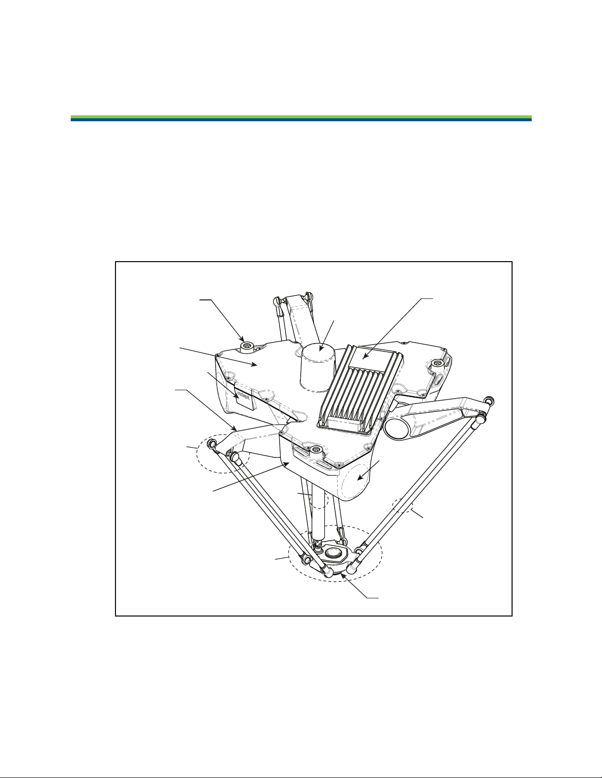
1.1 Adept Hornet 565 Robots, Product Description
The Adept Hornet 565™ robot is a three-axis parallel robot. The three identical axis motors
control movement of the robot tool in X, Y, and Z directions. On the four-motor model, a fourth
motor on the robot base turns a telescoping drive shaft, which provides theta rotation of the
tool flange through a geared platform.
The Hornet 565 robot is available in two models. One has a J4 platform, a theta motor and
theta drive shaft. This provides ±360° of rotation at the tool flange. The other model has a fixed
platform with no tool flange rotation.
Figure 1-1. Major Robot Components
Adept Hornet 565 Robot User's Guide, User’s Guide, Rev A
Page 11 of 142
Page 9
Chapter 1: Introduction
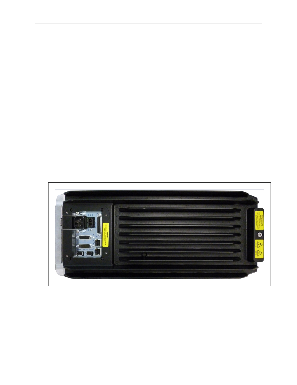
Adept eAIB Amplifier
The Adept Hornet 565 robot uses an Adept eAIB™ amplifier. The robot is powered and
controlled using the eAIB. The amplifiers and full servo control for the Adept Hornet 565 robot
are contained in the eAIB, which is embedded in the base of the robot. The eAIB also provides
the platform for running Adept’s eV+ OS and language.
The Adept eAIB features:
l
On-board digital I/O: 12 inputs, 8 outputs
l
Low EMI for use with noise-sensitive equipment
l
No external fan for quiet operation
l
8 kHz servo rate to deliver low positional errors and superior path following
l
Sine-wave commutation to lower cogging torque and improve path following
l
Digital feed-forward design to maximize efficiency, torque, and velocity
l
Temperature sensors on all amplifiers and motors for maximum reliability and easy
troubleshooting
l
Hardware-based E-Stop and Teach Restrict controls
For improved safety relative to European standards implemented in 2012.
Figure 1-2. Adept eAIB
Adept Hornet 565 Robot Base
The Adept Hornet 565 robot base is an aluminum casting that houses the four or three drive
motors, and supports the eAIB. It provides three mounting pads for attaching the base to a
rigid support frame. The Status Display panel is mounted on the side of the robot base.
Adept Hornet 565 Robot User's Guide, User’s Guide, Rev A
Page 12 of 142
Page 10
Chapter 1: Introduction
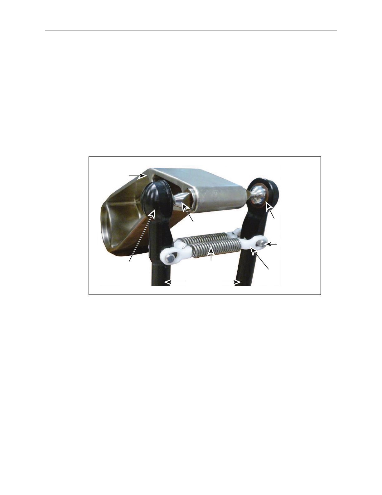
Inner
Arm
Ball Joint
Socket
Ball Joint
Socket Insert
Outer Arm Springs
Spring
Horseshoe
Pressed Pin
Ball Joint Stud
Outer Arms
Inner Arms
Three robot motors attach directly to the inner arms through high-performance gear reducers. If
the robot has a theta rotation motor, it is mounted at the top of the robot base. The following
figure shows an inner arm from a Hornet 565 robot. RIA-compliant hard stops limit the inner
arm motion to -53° and +114.6°.
Ball Joints, Outer Arms
The inner arm motion is transmitted to the platform through the outer arms, which are
connected between the inner arms and platform with precision ball joints. The outer arms are
carbon fiber epoxied assemblies with identical ball joint sockets at each end. A bearing insert
in each socket accepts the ball joint studs on the inner arms and platform, and allows for
approximately ± 60° of relative motion. No ball joint lubrication is required.
Figure 1-3. Ball Joint Assembly
Each pair of outer arms is held together with spring assemblies that pre-tension the ball joints.
The outer arms can be installed and removed without tools.
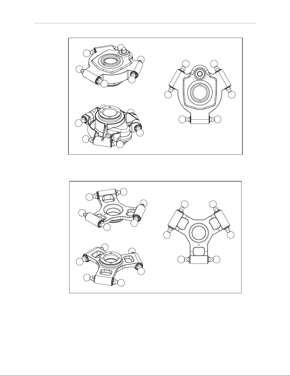
Platforms
The platform converts the motion of the Hornet 565 robot motors into Cartesian motion, and,
for the four-motor version, theta rotation of the robot tool flange.
The fixed platform, with no theta rotation, is stainless steel.
The J4 platform has a fourth motor, theta drive shaft, and geared J4 platform that can rotate its
tool flange ±360°. The platform is electroless-nickel-plated aluminum.
Both platforms have a 38 mm hole through their center, for users to route air lines or electric
cables to the tool flange.
For the J4 version of the Hornet 565 robot, a stainless steel theta drive shaft attaches to a Ujoint at both the platform and the J4 motor on the robot.
Adept Hornet 565 Robot User's Guide, User’s Guide, Rev A
Page 13 of 142
Page 11
Chapter 1: Introduction
Figure 1-4. J4 Platform (Electroless Nickel-plated Aluminum)
Figure 1-5. Fixed Platform (Stainless Steel)
Adept Hornet 565 Robot User's Guide, User’s Guide, Rev A
Page 14 of 142
Page 12
Chapter 1: Introduction
Platform Clocking
The J4 platform, which is rotational, is constructed such that the clocking, or rotational
alignment, of the platform relative to the robot base is critical. This is detailed in Aligning the
Platform with the Base on page 27.
Platform Shipping
l
The platform, outer arms, and theta drive shaft are removed.
l
The platform is shipped assembled as a unit.
You will need to connect the outer arms between the inner arms and the platform to
reassemble the robot. The outer-arm assemblies are interchangeable.
For the Hornet 565 robot with the J4 platform, you will also have to connect the
telescoping drive shaft that connects the platform to the fourth motor on the robot base.
Any end-effectors and their air lines and wiring are user-supplied.
Adept SmartController™ EX
The optional SmartController EXmotion controller supports tracking more conveyors, as well
as other options. Like the eAIB, the SmartController EX uses the eV+ operating system. It offers
scalability and support for IEEE 1394-based digital I/O and general motion expansion
modules. The SmartController EX also includes Fast Ethernet and DeviceNet.
Figure 1-6. Adept SmartController EX
Refer to the Adept SmartController EX User’s Guide for SmartController specifications.
1.2 Warnings, Cautions, and Notes in Manual
There are five levels of special alert notation used in Adept manuals. In descending order of
importance, they are:
DANGER:This indicates an imminently hazardous electrical
situation which, if not avoided, will result in death or serious
injury.
Adept Hornet 565 Robot User's Guide, User’s Guide, Rev A
Page 15 of 142
Page 13
Chapter 1: Introduction
DANGER:This indicates an imminently hazardous situation
which, if not avoided, will result in death or serious injury.
WARNING:This indicates a potentially hazardous electrical
situation which, if not avoided, could result in injury or major
damage to the equipment.
WARNING:This indicates a potentially hazardous situation
which, if not avoided, could result in injury or major damage to
the equipment.
CAUTION:This indicates a situation which, if not avoided,
could result in damage to the equipment.
NOTE:Notes provide supplementary information, emphasize a point or procedure,
or give a tip for easier operation.
1.3 Safety Precautions
l All personnel who install, operate, teach, program, or maintain the system must read
this guide, read the Adept Robot Safety Guide, and complete a training course for their
responsibilities in regard to the robot.
l All personnel who design the robot system must read this guide, read the Adept Robot
Safety Guide, and must comply with all local and national safety regulations for the
location in which the robot is installed.
l The robot system must not be used for purposes other than described in Intended Use of
the Robots on page 17. Contact Adept if you are not sure of the suitability for your
application.
l The user is responsible for providing safety barriers around the robot to prevent anyone
from accidentally coming into contact with the robot when it is in motion.
DANGER:An Adept Hornet robot can cause serious injury or
death, or damage to itself and other equipment, if the following
safety precautions are not observed:
l Power to the robot and its power supply must be locked out and tagged out before any
maintenance is performed.
Adept Hornet 565 Robot User's Guide, User’s Guide, Rev A
Page 16 of 142
Page 14
Chapter 1: Introduction
1.4 What to Do in an Emergency
Press any E-Stop button (a red push-button on a yellow background) and then follow the
internal procedures of your company or organization for an emergency situation. If a fire
occurs, use CO2to extinguish the fire.
1.5 Additional Safety Information
Adept provides other sources for more safety information.
The Manufacturer’s Declaration of Conformity (MDOC) lists all standards with which each
robot complies. See Manufacturer’s Declaration on page 18.
The Adept Robot Safety Guide provides detailed information on safety for Adept robots. It also
gives resources for more information on relevant standards. It ships with each robot manual,
and is also available from the Adept Document Library. For details, see Adept Document
Library on page 19.
1.6 Intended Use of the Robots
The Adept Hornet 565 robot is intended for use in parts assembly and material handling for
payloads up to 3 kg (6.6 lb).
See Robot Specifications on page 126 for complete information on the robot specifications.
Refer to the Adept Robot Safety Guide for details on the intended use of Adept robots.
1.7 Installation Overview
The system installation process is summarized in the following table. Also, refer to System
Installation on page 35.
NOTE:For dual-robot installations, see the Adept Dual-Robot Configuration
Procedure, which is available in the Adept Document Library.
Task to be Performed Reference Location
If purchased, mount the optional cable box. Options on page 81.
Mount the robot to a level, stable mounting frame. Mounting on page 24.
Attach the robot outer arms and platform. Attaching the Outer Arms on page
Attach the theta drive shaft, for the J4 platform. Attaching the Theta Drive Shaft on
Install the Front Panel and Pendant, if purchased,
and Adept ACE software.
Table 1-1. Installation Overview
28.
page 31.
System Cables, eAIB Only (no
SmartController EX) on page 35 and
Adept ACE Software on page 44.
Create a 24 VDC cable and connect it between the
robot and the user-supplied 24 VDC power supply.
Create a 200-240 VAC cable and connect it between Connecting 200-240 VAC Power to
Adept Hornet 565 Robot User's Guide, User’s Guide, Rev A
Page 17 of 142
Procedure for Creating 24 VDC Cable
on page 47.
Page 15

Chapter 1: Introduction
Task to be Performed Reference Location
the robot and the facility AC power source. Robot on page 49.
Install user-supplied safety barriers in the workcell. Installing User-Supplied Safety
Equipment on page 53.
Connect digital I/O through the robot XIO connector. Using Digital I/O on eAIB XIO
Connector on page 69.
Start the system, including system operation testing. Starting the System for the First Time
on page 76.
Install optional equipment, including end-effectors,
user air and electrical lines, external equipment, etc.
1.8 Manufacturer’s Declaration
The Manufacturer’s Declaration of Incorporation and Conformity for Adept robot systems can
be found on the Adept website, in the Download Center of the Support section.
http://www.adept.com/support/downloads/file-search
NOTE:The Download Center requires that you are logged in for access. If you are
not logged in, you will be redirected to the Adept website Login page.
1.
From the Download Types drop-down list, select Manufacturer Declarations.
2.
From the Product drop-down list, select Adept Hornet Robots category.
3.
Click Begin Search. The list of available documents is shown in the Search Results area,
which opens at the bottom of the page. You may need to scroll down to see it.
4.
Use the Description column to locate the document for the language you want, and then
click the corresponding Download ID number to access the Download Details page.
5.
On the Download Details page, click Download to open or save the file.
Options on page 81.
1.9 How Can I Get Help?
Refer to the How to Get Help Resource Guide (Adept P/N 00961-00700) for details on getting
assistance with your Adept software and hardware. Additionally, you can access information
sources on Adept’s corporate website:
http://www.adept.com
Related Manuals
This manual covers the installation, operation, and maintenance of an Adept Hornet 565 robot
system. There are additional manuals that cover programming the system and adding
optional components. See the following table. These manuals are available on the Adept
software media shipped with each system.
Adept Hornet 565 Robot User's Guide, User’s Guide, Rev A
Page 18 of 142
Page 16
Chapter 1: Introduction
Table 1-2. Related Manuals
Manual Title Description
Adept Robot Safety Guide Contains safety information for Adept robots.
Adept ACE User’s Guide Describes the installation and use of Adept ACE.
Adept T20 Pendant User's
Guide
Adept SmartController EX
User’s Guide
Describes the use of the optional Adept T20 manual control
pendant.
Contains complete information on the installation and
operation of the optional Adept SmartController EX and sDIO
products.
Adept SmartVision MX User's
Guide
Adept ePLC Connect 3 User’s
Guide
Instructions for use of the optional Adept SmartVision MX
industrial PC.
Describes the installation and use of the Adept ePLC Connect
3 software, for using a user-supplied PLC as controller.
Adept IO Blox User’s Guide Describes the IOBlox product.
Adept Dual-Robot
Configuration Procedure
Contains cable diagrams and configuration procedures for a
dual-robot system.
Adept Document Library
The Adept Document Library (ADL) contains documentation for Adept products. You can
access the ADL from the Adept website. Select:
Support > Document Library
from the Adept home page. To go directly to the Adept Document Library, type the following
URL into your browser:
http://www.adept.com/Main/KE/DATA/adept_search.htm
To locate information on a specific topic, use the Document Library search engine on the ADL
main page, or select one of the available menu options. To view a list of available product
documentation, use the menu links located above the search field.
Adept Hornet 565 Robot User's Guide, User’s Guide, Rev A
Page 19 of 142
Page 17

Chapter 2: Robot Installation
2.1 Transport and Storage
This equipment must be shipped and stored within the range –10 to +60° C (14 to 140° F).
Humidity should be less than 75%, non-condensing. The robot should be shipped and stored
in the Adept-supplied crate, which is designed to prevent damage from normal shock and
vibration. You should protect the crate from excessive shock and vibration.
Use a forklift, pallet jack, or similar device to transport the packaged equipment.
The robot must always be stored and shipped in an upright position. Do not lay the crate on
its side or any other non-upright position. This could damage the robot.
The Adept Hornet 565 robot J4 model weighs 52 kg (115 lb) with no options installed.
The fixed model weighs 48.6 kg (107 lb) with no options installed.
The crate weighs 68 kg (150 lb).
2.2 Unpacking and Inspecting the Adept Equipment
Before Unpacking
Carefully inspect all shipping crates for evidence of damage during transit. If any damage is
indicated, request that the carrier’s agent be present at the time the container is unpacked.
Upon Unpacking
Before signing the carrier’s delivery sheet, compare the actual items received (not just the
packing slip) with your equipment purchase order. Verify that all items are present and that
the shipment is correct and free of visible damage.
l
If the items received do not match the packing slip, or are damaged, do not sign the
receipt. Contact Adept as soon as possible (see How Can I Get Help? on page 18).
l
If the items received do not match your order, please contact Adept immediately.
Retain all containers and packaging materials. These items may be necessary to settle claims
or, at a later date, to relocate the equipment.
Unpacking
The Hornet 565 robot is shipped in a crate that holds the robot base, outer arms, platform,
theta drive shaft, and any accessories ordered. The crate is made of wood.
The top of the crate should be removed first.
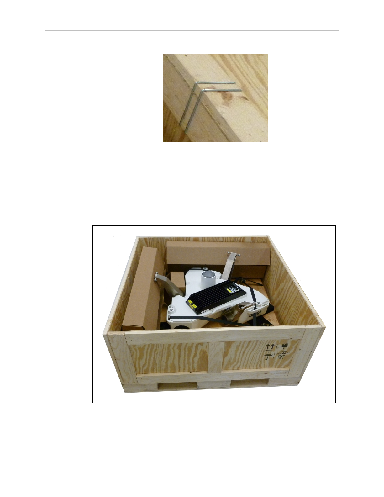
1.
Remove the Klimp®fasteners holding the top to the rest of the crate. See the following
figure.
Adept Hornet 565 Robot User's Guide, User’s Guide, Rev A
Page 21 of 142
Page 18
Chapter 2: Robot Installation
Figure 2-1. Klimp Fastener on Crate
The robot base is shipped with the inner arms attached. The outer arms are in a
cardboard box, assembled in pairs. The platform is shipped fully assembled, but
separate from the robot base and outer arms. The theta drive shaft is shipped with Ujoints attached, but separate from the robot and platform.
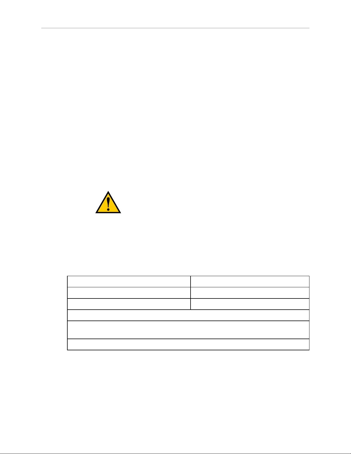
2.
Lift the top off of the crate sides, and set it aside.
Figure 2-2. Crate, with Top Removed
3.
Remove all cardboard boxes from inside the crate.
Adept Hornet 565 Robot User's Guide, User’s Guide, Rev A
Page 22 of 142
Page 19
Chapter 2: Robot Installation
These will include the outer arms, theta drive shaft, and platform.
4.
Remove all fasteners (Klimp and lag)holding the crate sides to the base, and lift off the
crate sides.
The four sides will come off as a single piece, so this requires two people lifting from
opposite sides of the crate.
You will be left with the robot base, with eAIB and inner arms, attached to the pallet.
The robot base is held to the pallet with tie-downs.
5.
Remove the tie-downs.
NOTE:The pallet will not fit inside most frames, so the robot will need to be
manually moved to the inside of the frame for mounting.
2.3 Repacking for Relocation
If the robot or other equipment needs to be relocated, reverse the steps in the installation
procedures in this chapter. Reuse all original packing containers and materials and follow all
safety notes used for installation. Improper packaging for shipment will void your warranty.
CAUTION:The robot must always be shipped in an upright
orientation.
2.4 Environmental and Facility Requirements
The Hornet 565 robot system installation must meet the operating environment requirements
shown in the following table.
Table 2-1. Robot System Operating Environment Requirements
Ambient temperature 1 to 40° C (34 to 104° F)
Humidity 5 to 90%, non-condensing
Altitude up to 2000 m (6500 ft)
NOTE: For robot dimensions, see Dimension Drawings on page 123.
NOTE: For power requirements, see Specifications for 24 VDC Robot and Controller Power
on page 46 and Specifications for AC Power on page 49.
NOTE: For chemical cleaning information, refer to Chemical Compatibility on page 96.
2.5 Mounting Frame
The design of the robot mounting frame is the user’s responsibility.
l
The flatness of the frame mounting tabs is critical. See Robot-to-Frame Considerations
(following) and Mounting Surfaces on page 25.
Adept Hornet 565 Robot User's Guide, User’s Guide, Rev A
Page 23 of 142
Page 20

Chapter 2: Robot Installation
l
The frame must be stiff enough to prevent excessive vibration.
l
The eAIB must be removable from the robot without removing the robot from the frame.
This is needed for maintenance and inspection of the robot.
The Hornet 565 robot is designed to be mounted above the work area suspended on a usersupplied frame. The frame must be adequately stiff to hold the robot rigidly in place while the
robot platform moves within the workspace.
While Adept does not offer robot frames for purchase, and the frame design is the
responsibility of the user, we provide some general guidelines as a service to our users.
Any robot’s ability to settle to a fixed point in space is governed by the forces, masses, and
accelerations of the robot. Since “every action has an equal and opposite reaction”, these forces
are transmitted to the robot frame and cause the frame and base of the robot to move and
possibly vibrate in space. As the robot system works to position the tool flange relative to the
base of the robot, any frame or base motion will be “unobservable” to the robot system, and
will be transmitted to the tool flange. This transmitted base motion will result in inertial
movement of the tool flange mass, and will cause disturbance forces to be introduced into the
robot control system. These disturbance forces cause “work” to be done by the robot servo
control system which may result in longer settling times for robot operations.
It is important to note that, even after the system reports the robot to be fully settled, the tool
flange will still be moving by any amount of motion that the suspended base of the robot may
be experiencing.
Robot-to-Frame Considerations
The Hornet 565 robot has a moderately-complex mounting requirement due to the nature of
the parallel-arm kinematics and the need to minimize the robot size and mass. Arm Travel
Volume on page 125 shows the inner arm travel and how it may encroach on the robot
mounting points. As a starting point, for a frame that is 1440 mm in the X and Ydirections,
(allowing use of the full range of the robots), you should attempt to attain a frame frequency of
25 Hz.
For specialized applications, such as heavy payloads and/or aggressive moves, you may want
to attain a frame frequency of 40 Hz.
In general, a smaller frame will yield a higher frequency. If you aren’t going to use the entire
work envelope, you can increase the frequency simply by using a smaller frame.
A lower frequency frame, more aggressive robot moves, and heavier payloads will all
contribute to longer settling times.
Mounting
Dimension Drawings on page 123 shows the mounting hole pattern for the Hornet 565 robot.
Note the hole location and mounting pad tolerances for position and flatness.
Deviation from this flatness specification will, over time, cause a possible loss of robot
calibration.
NOTE:Adept suggests welding the robot mounting tabs as a last step in the frame
fabrication, using a flat surface as a datum surface during the tack welding
operation.
Adept Hornet 565 Robot User's Guide, User’s Guide, Rev A
Page 24 of 142
Page 21
Chapter 2: Robot Installation
2.6 Mounting the Robot Base
Robot Orientation
Adept recommends mounting the Hornet 565 robot so that the Status Display Panel faces
away from the conveyor belt. Although the work envelope of the robot is symmetrical, this
orientation gives better access to the status display. It also orients the arm loading for
aggressive moves across the belt.
This orientation places the robot World Y-axis along the conveyor belt, and the X-axis across
the belt. See Mounting Dimensions on page 123.
Mounting Surfaces
Mounting surfaces for the robot mounting tabs must be within 0.75 mm of a flat plane.
CAUTION:Failure to mount the Hornet 565 robot within
0.75mm of a flat plane will result in inconsistent robot locations.
NOTE:The base casting of the robot is aluminum and can be dented if bumped
against a harder surface.
CAUTION:Do not attempt to lift the robot from any points
other than with slings as described here.
Mounting Procedure
The Hornet 565 robot has three mounting pads. Each pad has one hole with an M12 x 1.75
spring-lock Heli-Coil®.
1.
Position the robot directly under the mounting frame.
NOTE:The pallet will not fit inside most frames, so the robot will need to be
manually moved to the inside of the frame.
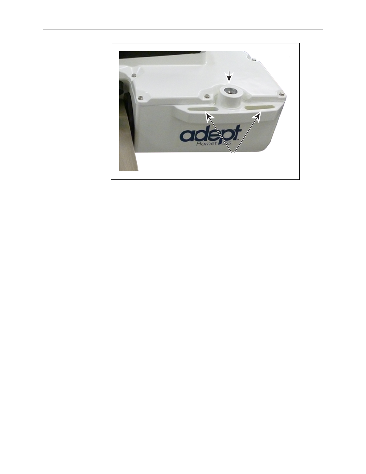
2.
Put nylon straps through the six slots near the three mounting pads.
The following figure shows two of these slots.
Adept Hornet 565 Robot User's Guide, User’s Guide, Rev A
Page 25 of 142
Page 22
Chapter 2: Robot Installation
Mounting Pad
Lifting Slots
Figure 2-3. Two of Six Lifting Slots
3.
Take up any slack in the straps.
The mechanism you use for lifting the straps will be dependent on the frame design, so
it is not specified here.
4.
Slowly lift the robot base up, keeping the holes in the robot base pads and the frame
pads aligned, until the top surfaces of the robot base pads are touching the bottom
surfaces of the frame mounting pads.
5.
Follow the instructions in Install Mounting Hardware that follow.
Install Mounting Hardware
Because of the possible variability of the mounting frames, mounting hardware is usersupplied. The bolts need to be M12-1.75, either stainless steel or zinc-plated steel. The threads
must engage 24 mm (0.94 in.) of the robot base threads (Heli-Coil), for sufficient support.
When mounting the robot, note the following:
l
Verify that the robot is mounted squarely before tightening the mounting bolts.
l
Insert the bolts through the holes in the frame and into the threaded holes in the robot
base mounting pads.
l
Ground the robot base to the mounting frame.
Refer to Grounding Robot Base to Frame on page 53.
l
Tighten the bolts to 61 N·m (45 ft-lb).
NOTE:The robot base-mounting tabs have spring-lock Heli-Coils in the M12 holes,
so lock washers are not needed on the M12 mounting bolts.
Adept Hornet 565 Robot User's Guide, User’s Guide, Rev A
Page 26 of 142
Page 23
Chapter 2: Robot Installation
Joint 3
eAIB
Robot
Base
Tool Flange
Platform
and Ball
Joints
Theta
Drive
Shaft
Ball Joints,
Joint 1
Outer Arms
Status Display Panel
Joint 4
Cover
Robot Base
Cover
Inner Arm
Motor Plug
Mounting Pad
x3
Joint 2
Inner Arm
(Spring Assemblies
not shown)
NOTE: Check the tightness of the mounting bolts one week after initial installation,
and then recheck every 3 months. See Checking Robot Mounting Bolts on page 98.
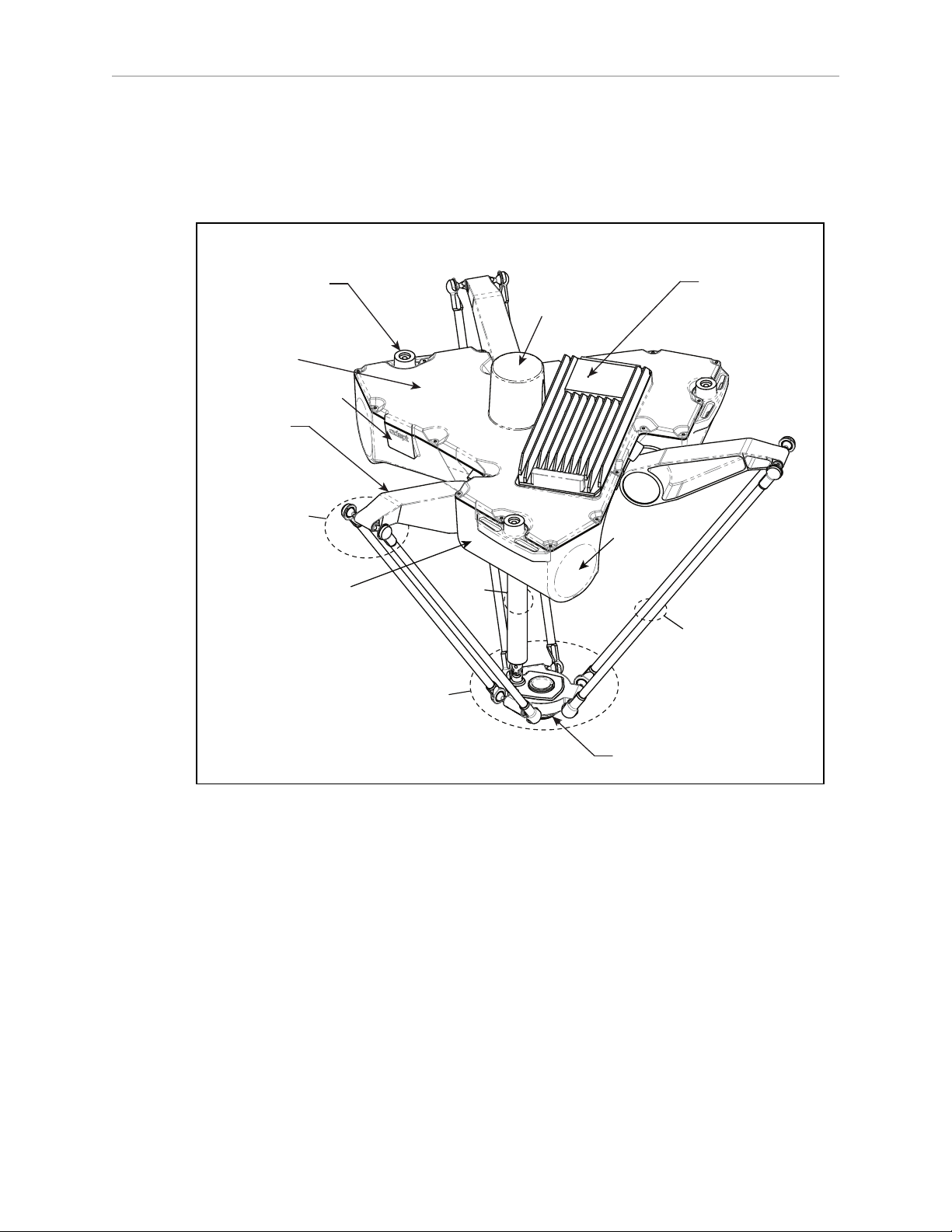
2.7 Attaching the Outer Arms, Platform, and Theta Drive Shaft
Figure 2-4. Major Robot Components
The Adept Hornet 565 robot platform is attached to the inner arms by the outer arms.
NOTE:Except for attaching the outer arms and theta drive shaft, the platform is
shipped fully-assembled.
Aligning the Platform with the Base
NOTE:The fixed platform is symmetrical, and can be mounted in any rotational
position. The tool flange must be down, away from the robot body.
This section only applies to the J4 platform.
Adept Hornet 565 Robot User's Guide, User’s Guide, Rev A
Page 27 of 142
Page 24
Chapter 2: Robot Installation
Theta
Drive
Shaft
Attachment
Joint 1
Joint 3 Joint 2
Tool
Flange
X+
Y+
The rotational alignment of the platform with the base is critical to the correct operation of the
robot.
CAUTION:Incorrect alignment of the platform will result in
incorrect robot performance.
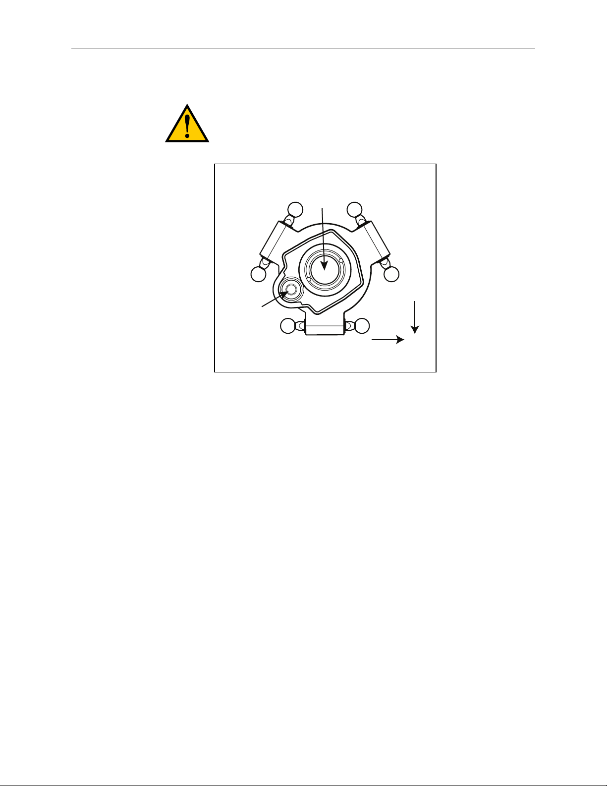
Both the theta drive shaft attachment on the robot base and the platform are offset by about 2
in. from the centers of the robot base and tool flange. The platform should be attached so that
the shaft aligns with the J4 motor, between Joint 1 and Joint 3 on the robot base. Joint 1 in the
preceding figure should connect to motor 1, which is immediately to the right of the Status
Display panel on the robot base.
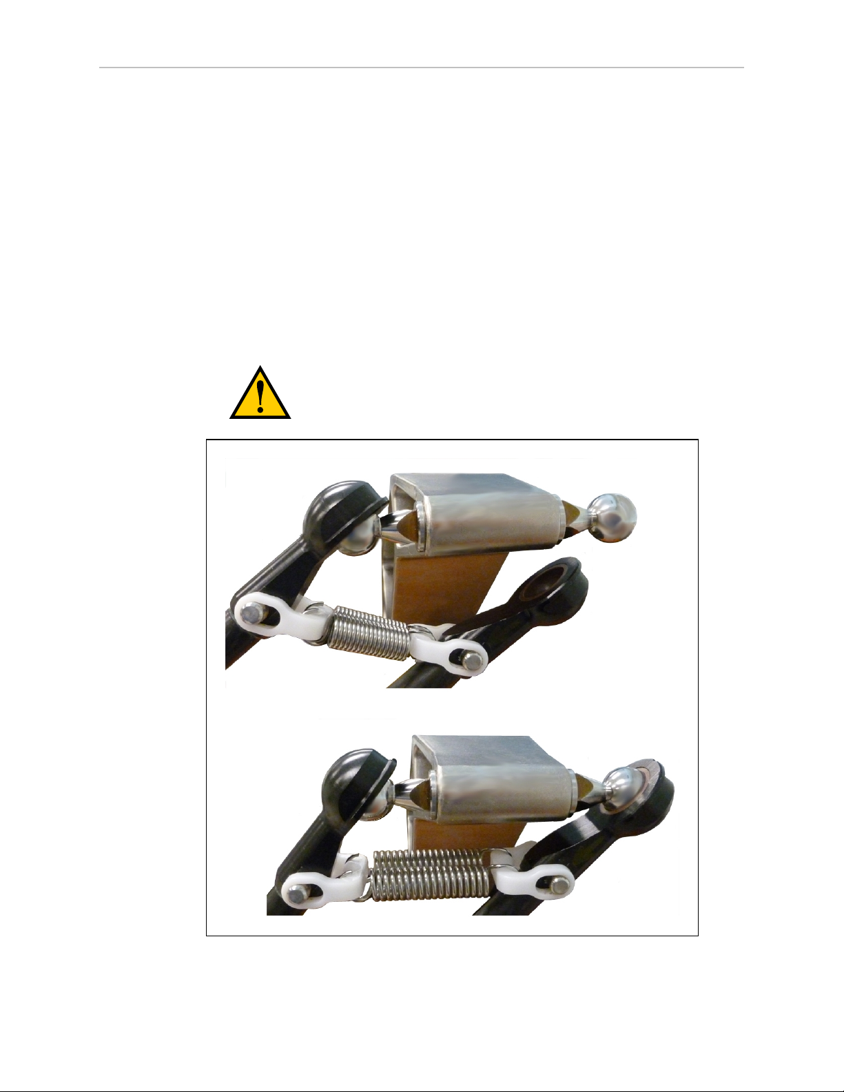
Attaching the Outer Arms
One pair of outer arms attaches between each inner arm and the platform. No tools are
needed.
l
Each outer arm has a ball joint socket at each end.
l
The inner arms and the platform have corresponding pairs of ball studs.
Figure 2-5. J4 Platform Orientation, Top View
Adept Hornet 565 Robot User's Guide, User’s Guide, Rev A
Page 28 of 142
Page 25
Chapter 2: Robot Installation
Inner
Arm
Ball Joint
Socket
Ball Joint
Socket Insert
Outer Arm Springs
Spring
Horseshoe
Pressed Pin
Ball Joint Stud
Outer Arms
Figure 2-6. Inner Arm Ball Studs
WARNING:Pinch hazard. Ball joints are spring-loaded. Be
careful not to pinch your fingers.
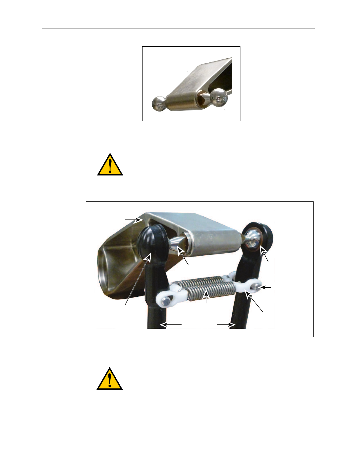
l
Outer arm pairs are shipped assembled. Each pair has two springs and two horseshoes
at each end. See the following figure.
Adept Hornet 565 Robot User's Guide, User’s Guide, Rev A
Figure 2-7. Ball Joint Assembly
CAUTION:Ensure that the bearing insert is in place in the end of each
outer arm.
Page 29 of 142
Page 26
Chapter 2: Robot Installation
NOTE:In the following steps, take care not to trap debris between the ball studs
and their sockets.
NOTE: The procedure for attaching outer arms is the same for both platforms.
1.
Attach one pair of outer arms to each inner arm.
a.
As illustrated in the following figure, the outer arm assembly is most easily
achieved by pivoting the two arms away from each other lengthwise. This
requires the least stretching of the spring to attach the ball joints.
b.
Slip one ball joint socket over the corresponding ball stud.
c.
Swing the bottom end of the outer arm pair sideways as you slip the other ball
joint socket over the corresponding ball stud.
CAUTION:Do not overstretch the outer arm springs. Separate
the ball joint sockets only enough to fit them over the ball studs.
Figure 2-8. Installing Ball Joints
Adept Hornet 565 Robot User's Guide, User’s Guide, Rev A
Page 30 of 142
Page 27
Chapter 2: Robot Installation
2.
Attach one pair of outer arms to each of the three pairs of ball studs on the platform.
a.
Swing the bottom end of the outer arm pair to the right, as far as possible.
b.
Slip the right ball joint socket over the right ball stud. (Move the platform
as needed to do this.)
c.
Move the platform and outer arm pair to the left as you slip the left ball
joint socket over the corresponding ball stud.
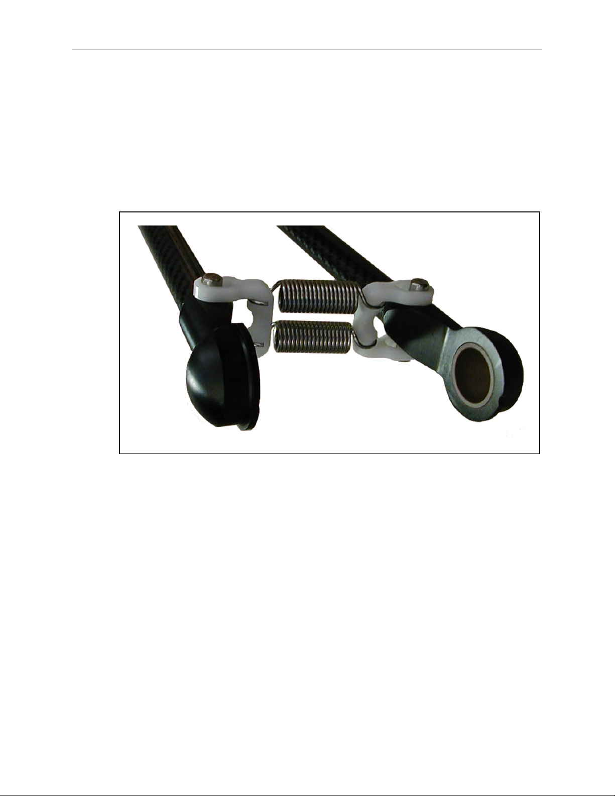
3.
Ensure that all spring hooks are fully-seated in the grooves of the horseshoes, as shown
in the following figure:
Figure 2-9. Horseshoe and Spring Assembly
Attaching the Theta Drive Shaft
NOTE:The fixed platform does not use a theta drive shaft, so this section does not
apply to systems with a fixed platform.
Each U-joint has two identical ends. When the theta drive shaft is shipped, it will have one
end of a U-joint attached to each end. One connects to the J4 motor drive, the other connects to
a shaft on the top of the J4 platform.
Adept Hornet 565 Robot User's Guide, User’s Guide, Rev A
Page 31 of 142
Page 28
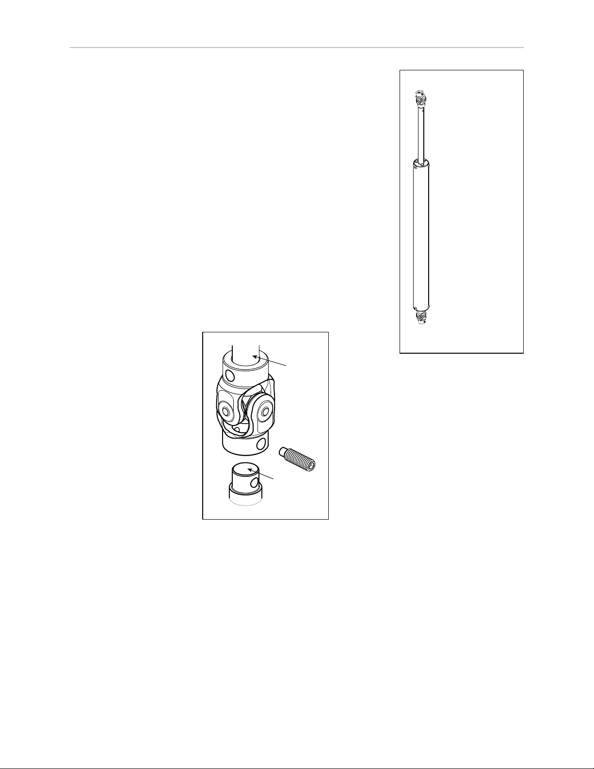
Chapter 2: Robot Installation
Top U-Joint
at J4 Motor
Upper Section
of Drive Shaft
Lower Section
of Drive Shaft
Bottom U-Joint
at J4 Platform
Theta
Drive
Shaft
Set
Screw
U-Joint
J4 Shaft
(Motor or
Platform)
l
Connect the top U-joint to the drive shaft of the J4 motor.
The top (J4 motor)end of the drive shaft is labeled with
a temporary label, indicating Top. Remove the label
before use.
l
Connect the bottom U-joint to the shaft on top of the J4
platform.
NOTE:The drive shaft is not symmetrical. There is a top
and a bottom. Installing the drive shaft upside-down
will degrade system performance. Note the orientation
label on the drive shaft. Look for a “Top” label on the
drive shaft.
To attach the free end of the U-joints:
1.
Slide the end of the U-joint over the shaft (platform or J4
motor).
The fit will be fairly tight.
The hole in the side of the U-joint needs to line up with
the hole in the shaft.
Figure 2-10. U-Joint
2.
Screw an M6 x 20 dog point set screw (included) through the shaft, going through the
hole in the side of the U-joint, and into the blind hole on the opposite side of the U-joint.
The U-joint is not threaded.
l
Use Loctite 242.
l
Tighten to 5 N-m (3.7 ft-lbf)of torque. The head of the set screw should be flush
with the outer surface of the U-joint.
For the top U-joint, use a 3 mm hex key, with a 10 - 15 mm short leg. There is not
enough room at the J4 motor shaft to use a standard hex key.
Adept Hornet 565 Robot User's Guide, User’s Guide, Rev A
Page 32 of 142
Page 29
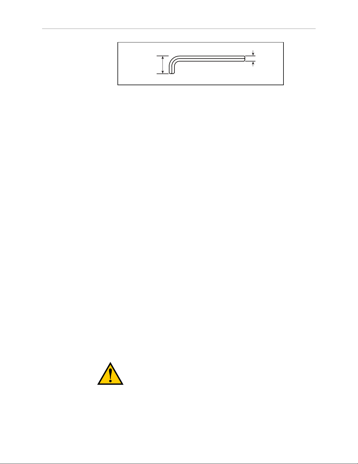
10 - 15 mm
3 mm
NOTE:The platform and the J4 motor will have to be aligned after the ACE
software is installed and the robot is power-on. See Aligning the Platform and J4
Motor on page 78.
2.8 End-Effectors
You are responsible for providing and installing any end-effector or other tooling, as well as
vacuum lines and wiring to the end-effector.
See the drawing Tool Flange Dimensions, Both Platforms on page 124 for dimensions of the
tool flange.
Chapter 2: Robot Installation
Figure 2-11. Short 3 mm Hex Key
Attaching an End-Effector
You can attach end-effectors to the tool flange using either four M6 x 1.0 screws, or a ring
clamp. Hardware for both methods is supplied in the accessories kit.
NOTE:The combined weight of the end-effector and the payload must not exceed
the maximum rated payload.
Aligning an End-Effector
A 6 mm diameter x 12 mm dowel pin (user-supplied) fits in a hole in the tool flange and can
be used as a keying or anti-rotation device in a user-designed end-effector.
Grounding
If hazardous voltages are present at the end-effector, you must install a ground connection to
the end-effector. See Grounding Robot-Mounted Equipment on page 52.
Accessing Vacuum
The hole through the center of the tool flange has been made as large as possible to allow
vacuum and/or electric lines to pass through.
WARNING:Do not tap the tool flange, as this would weaken it.
Adept Hornet 565 Robot User's Guide, User’s Guide, Rev A
Page 33 of 142
Page 30

Chapter 2: Robot Installation
Routing End-effector Lines
End-effector lines (either vacuum/air lines or electrical wires) can be routed to the platform by:
l
Attaching them to the inner and outer arms, and then to the platform.
l
Routing them from the robot support frame to the outer arms.
l
Routing them from the robot base directly to the platform.
If end-effector lines are attached to the outer arms to reach the end-effector, either directly from
the frame, or along the inner arms:
l
Make every attempt to keep the load on the outer arms as evenly-balanced as possible.
The added weight should be attached symmetrically about the platform center.
l
Verify that the arms can be fully-extended without interference from the lines.
Ensure that there is enough line to reach the end-effector at all platform locations.
l
Verify that the platform can be fully-rotated at all positions without affecting or being
affected by the lines.
l
Verify that any service loop or excess line does not hang down below the end-effector at
any platform position.
l
Verify that excess line cannot become tangled in the outer arms or platform.
If end-effector lines are attached directly to the bottom of the robot base to reach the endeffector:
l
Lines attached to the robot base need some form of retraction mechanism or service
loop to take up the slack when the platform is near the robot base.
l
Ensure that the lines (and retraction mechanism) do not apply significant force, in any
direction, to the platform.
l
Ensure that lines going to the robot base do not block your view of the status LED.
l
Ensure that lines going to the robot base do not interfere with the inner arm movement.
User-added end-effector lines:
l
Should be checked for the entire work envelope being utilized. They must reach without
being pulled, and without impeding arm or platform movement.
l
Cannot pull against the platform with significant force. Robot performance will be
affected.
l
Must be considered as part of the payload, if they add weight to the platform or outer
arms.
l
Are the user’s responsibility for maintenance.
They are not covered in the Maintenance section of this manual.
Adept Hornet 565 Robot User's Guide, User’s Guide, Rev A
Page 34 of 142
Page 31

Chapter 3: System Installation
DC
IN
24 V
GND
AC
200 -
240 V
Ø
1
XBELTIO
XIO
Servo
ENETENET
XSYSTEM
Adept
Hornet 565
Robot
24 VDC, 6 A
Power Supply
200-240 VAC
10 A
single-phase
AC Power
Cable
DC Power
Cable
Front Panel
Cable
Front Panel (option)
User-Supplied PC
running Adept ACE Software
T20 Adapter
Cable
XMCP Jumper Plug
XMCP
XFP
XUSR
XUSR Jumper Plug
eAIB
XSYSTEM
Cable
Robot Interface
Panel
XUSR for:
- User E-Stop/Safety Gate
- Muted Safety Gate
The Jumper Plug is required if
neither of these is used
Ethernet
from PC
T20 Bypass Plug
User-Supplied
Ground Wire
T20 Pendant (option)
Either T20 Pendant,T20 Bypass Plug, or
XMCP Jumper Plug must be used
2
3
4a
A
B
G
H
J
4a
4
4
1
5
6
7
9
8
L
M
Q
P
E
K
D
N
3
85 - 264 VAC
Universal
Input
DC
IN
24V
GND
AC
200 240V
Ø
1
XBELTIO
XIO
Servo
ENETENET
XSYSTEM
Ethernet to eAIB
FP Jumper Plug
F
Either Front Panel or
FP plug must be used
3a
2a
C
Ethernet from eAIB
to SmartVision MX
R
9b
9a
User-supplied
Switch
User-supplied
PLC Option
Adept SmartVision MX (option)
R
S
7a
M
DC Power
Cable
Camera
(option)
T
10
3.1 System Cables, eAIB Only (no SmartController EX)
See System Installation on page 35 for additional information on system grounding.
Figure 3-1. System Cable Diagram, eAIB Only
Adept Hornet 565 Robot User's Guide, User’s Guide, Rev A
Page 35 of 142
Page 32

Chapter 3: System Installation
List of Cables and Parts
Open the Accessory box and locate the eAIB XSYSTEM cable. Connect the cables and
peripherals as shown in the preceding figure. Parts and steps are covered in the following two
tables.
Part Cable and Parts List Part # Part of: Notes
A eAIB XSYSTEM Cable Assembly 13323-000 standard, eAIB
B User E-Stop, Safety Gate n/a n/a user-supplied
C XUSR Jumper Plug 04736-000 13323-000 standard, eAIB
D Front Panel (option) 90356-10358 or user-supplied
E Front Panel Cable 10356-10500 90356-10358 or user-supplied
F Front Panel Jumper Plug 10053-000 13323-000 standard, eAIB
G XMCP Jumper Plug 04737-000 13323-000 standard, eAIB
H T20 Bypass Plug 10048-000 10055-000 standard, T20
J T20 Adapter Cable 10051-003 10055-000 standard, T20
K T20 Pendant (option) 10055-000 option
L AC Power Cable (option) 04118-000 90565-010 or user-supplied
M 24 VDC Power Cable (option) 04120-000 90565-010 or user-supplied
N 24 VDC, 6 A Power Supply
04536-000 90565-010 or user-supplied
(option)
P Ethernet Cable - PC -> PLC
n/a n/a user-supplied
(Only while programming PLC)
Q Ethernet Cable - switch -> eAIB n/a n/a user-supplied
R Ethernet Cable - switch ->
n/a n/a user-supplied
SmartVisionMX
S Ethernet switch, cable for
SmartVision MX.
n/a n/a option,
user-supplied
T Camera and cable n/a n/a option
The XUSR, XMCP, and XFP jumpers intentionally bypass safety connections so you can test
the system functionality during setup.
WARNING:Under no circumstances should you run an Adept
system, in production mode, with all three jumpers installed.
This would leave the system with no E-Stops.
Adept Hornet 565 Robot User's Guide, User’s Guide, Rev A
Page 36 of 142
Page 33

Chapter 3: System Installation
Cable Installation Overview
Power requirements for the SmartVision MX industrial PC are covered in that user guide. For
24 VDC, both the Hornet 565 robot and a SmartVision MX can usually be powered by the
same power supply.
Step Connection Part
1 Connect eAIB XSYSTEM cable to XSYSTEM on eAIB. A
2 Connect a user E-Stop or Muted Safety Gate to the eAIB XSYSTEM cable XUSR
B
connector or
2a verify XUSR jumper plug is installed in eAIB XSYSTEM cable XUSR connector. C
3 Connect Front Panel cable to optional Front Panel and eAIB XSYSTEM cable
D, E
XFP connector or
3a if using user-supplied Front Panel, connect Front Panel to eAIB XSYSTEM cable
A, E
XFP. See warning after table.
4 Connect T20 adapter cable to eAIB XSYSTEM cable XMCP connector or J, K
4a if no T20, install XMCP jumper
or
T20 Adapter Cable with T20 bypass plug.
5 Connect user-supplied ground to robot. See Grounding the Adept Robot System
G
or
H
n/a
on page 52.
6 Connect 200-240 VAC to AC Input on eAIB Interface Panel; secure with clamp. L
7 Connect 24 VDC to DC Input on Interface Panel. N,
M
7a Connect 24 VDC and shield ground to SmartVision MX, if used. See
SmartVision MX user's guide for location.
N,
M
8 Connect Ethernet cable from PC to PLC, if a PLC is used. P
9 Connect Ethernet cable from PLC to switch, if a PLC is used. S
9a Connect Ethernet cable from switch to eAIB. Q, S
9b Connect Ethernet cable from SmartVision MX, if used, to switch. R, S
10 Connect optional camera and cable to SmartVision MX, if used. T
NOTE:A front panel can be purchased with each Hornet 565 robot system, but you
can choose to replace its functionality with equivalent circuits. That is beyond the
scope of this guide.
WARNING:A front panel must be installed to provide an EStop button and to enable power to the robot. To operate
without the Adept Front Panel, the user must supply equivalent
circuits.
Adept Hornet 565 Robot User's Guide, User’s Guide, Rev A
Page 37 of 142
Page 34

Optional Cables
NOTE:The following cables are not covered in the steps in the preceding table.
Part Description Notes
Chapter 3: System Installation
XIO Breakout Cable, 12 inputs/
8 outputs, 5 M
eAIB XBELT IO Adapter Cable Available as option
The XIO Breakout cable is for using the I/O on the eAIB. See XIO Breakout Cable on page 74.
Cables for adding belt encoders are covered in System Cables for Systems with Belt Encoders
on page 42.
Available as option
Adept Hornet 565 Robot User's Guide, User’s Guide, Rev A
Page 38 of 142
Page 35

Chapter 3: System Installation
Adept SmartController EX (option)
T20 Adapter
Cable
XMCP
Jumper
Plug
T20 Bypass
Plug
T20
Pendant
(option)
Either T20 Pendant,
T20 Bypass Plug, or
XMCP J
umper Plug
must be used
Adept SmartVision MX (option)
Front
Panel
Cable
Front Panel (option)
FP
Jumper
Plug
Either Front Panel or
FP plug must be used
Adept Hornet
565 Robot
24 VDC, 6 A
Power Supply
200-240 VAC
10 A
single-phase
AC Power Cable
DC Power
Cable
DC Power
Cable
User-Supplied PC
running PLC or ACE
Programming Software
eAIB
XSYS
Cable
Ethernet from
PC to PLC,
Switch, or
SmartController EX
User-Supplied
Ground Wire
85 - 264 VAC
Univ
ersal
Input
DC
IN
24V
GND
AC
200 240V
Ø
1
XBELTIO
XIO
Servo
ENETENET
XSYSTEM
Ethernet to
SmartController EX
User-supplied Camera (option)
User-Supplied
Ground Wire
User-Supplied
Ground Wire
Robot Interface Panel
from Controller
XSYS Port
IEEE
1394
XUSR Jumper Plug
XUSR for:
- User E-Stop/Safety Gate
- Muted Safety Gate
- Jumper plug required
when not used
User-supplied
switch (option)
Optional User-supplied PLC
DC
IN
24
V
GND
AC
200 -
240 V
Ø
1
XBELTIO
XIO
Servo
ENETENET
XSYSTEM
D
A
E
3
1
6
8
P
9
Q
3
3a
F
C
2
2a
B
4a
4
4a
4
G
H
J
K
L
M
M
N
7
5
7
5b
5a
7a
10
10
1
9b
S
R
R
3.2 System Cables, with SmartController EX
When the optional SmartController EX is included in the system, the Pendant, Front Panel,
and XUSR connections, if used, must connect to the SmartController EX.
Installing a SmartController EX Motion Controller
Refer to the Adept SmartController EX User’s Guide for complete information on installing the
optional Adept SmartController EX. This list summarizes the main steps.
1.
Mount the SmartController EX and optional front panel.
2.
Connect the optional front panel to the SmartController EX.
Figure 3-2. System Cable Diagram with SmartController EX
Adept Hornet 565 Robot User's Guide, User’s Guide, Rev A
Page 39 of 142
Page 36

3.
Connect the optional pendant to the SmartController EX.
4.
Connect user-supplied 24 VDC power to the controller.
Instructions for creating the 24 VDC cable, and power specification, are covered in the
Adept SmartController EX User’s Guide.
5.
Install a user-supplied ground wire between the SmartController EX and ground.
List of Cables and Parts
Part Cable and Parts List Notes
A eAIB XSYS Cable standard, eAIB
B User E-Stop, Safety Gate user-supplied
C XUSR Jumper Plug standard,
D Front Panel (option) or user-supplied
E Front Panel Cable or user-supplied
F Front Panel Jumper Plug standard,
Chapter 3: System Installation
SmartController EX
SmartController EX
G XMCP Jumper Plug standard,
SmartController EX
H T20 Bypass Plug standard, T20
J T20 Adapter Cable standard, T20
K T20 Pendant (option) option
The following three items are available, as an option, in the Adept
power supply/cable kit 90565-010
L AC Power Cable user-supplied/option
M 24 VDC Power Cable user-supplied/option
N 24 VDC, 6 A Power Supply user-supplied/option
P Ethernet Cable, PC -
user-supplied
SmartController
Q Ethernet Cable, PC -
user-supplied, option
SmartVisionMX
R IEEE 1394 cable standard
S Camera and cable user-supplied, option
The XUSR, XMCP, and XFP jumpers intentionally bypass safety connections so you can test
the system functionality during setup.
Adept Hornet 565 Robot User's Guide, User’s Guide, Rev A
Page 40 of 142
Page 37

Chapter 3: System Installation
WARNING:Under no circumstances should you run an Adept
system, in production mode, with all three jumpers installed.
This would leave the system with no E-Stops.
Cable Installation Overview
Step Connection Part
1 Connect eAIB XSYS cable to XSYSTEM on eAIB A
2 Connect a user E-Stop or Muted Safety Gate to the XUSR connector or B
2a verify XUSR jumper plug is installed in XUSR connector. C
3 Connect Front Panel cable to optional Front Panel and XFP connector or D, E
3a if using user-supplied Front Panel, connect Front Panel to eAIB XSYSTEM cable
A, E
XFP. See warning after table.
4 Connect Pendant adapter cable to XMCP connector or J, K
4a if no Pendant, install XMCP jumper or bypass plug. G or
H
5 Connect user-supplied ground to robot. See robot user's guide for location. n/a
5a Connect user-supplied ground to SmartController EX. See SmartController
n/a
EXuser's guide for location.
5b Connect user-supplied ground to SmartVision MX, if used. See SmartVision
n/a
MX user's guide for location.
6 Connect 200-240 VAC to AC Input on eAIB; secure with clamp. L
7 Connect 24 VDC to DC Input on eAIB and SmartController EX. N,M
7a Connect 24 VDC to SmartVision MX, if used. N,M
8 Connect Ethernet cable from PC to SmartController EX. P
9a Connect Ethernet cable to SmartVision MX, if used. Q
10 Connnect IEEE1394 cable between SmartController EXand eAIB SmartServo R
11 Connect optional camera and cable to SmartVision MX, if used. S
Less Common Cables
NOTE:The following cables are not covered in the steps in the preceding table.
Adept Hornet 565 Robot User's Guide, User’s Guide, Rev A
WARNING:A front panel must be installed to provide an EStop button and to enable power to the robot. To operate
without the Adept Front Panel, the user must supply equivalent
circuits.
Page 41 of 142
Page 38

Chapter 3: System Installation
DC
IN
24 V
GND
AC
200 -
240 V
Ø
1
XBELTIO
XIO
Servo
ENETENET
XSYSTEM
XBELT IO
13463-000
HDB26
FEMALE
BELT
ENCODER
FORCE/
EXPIO
RS232
BELT ENC.
09443-000
DB15
FEMALE
12
RS-232
Force/EXPIO
Adept
Hornet
Robot
24 VDC, 6 A
Power Supply
200-240 VAC
10 A
single-phase
AC Power
Cable
DC Power
Cable
Front Panel
Cable
Front Panel
User-Supplied PC
running Adept ACE Software
T20 Adapter
Cable
XMCP Jumper Plug
XMCP
XFP
XUSR
XUSR Jumper Plug
eAIB
XSYSTEM
Cable
Robot Interface
Panel
XUSR for:
- User E-Stop/Safety Gate
- Muted Safety Gate
The Jumper Plug is required if
neither of these is used
Ethernet
from PC
T20 Bypass Plug
User-Supplied
Ground Wire
T20 Pendant (option)
Either T20 Pendant,T20 Bypass Plug, or
XMCP Jumper Plug must be used
2
3
4a
A
B
G
H
J
4a
4
4
1
5
6
7
8
L
M
Q
E
K
D
N
3
85 - 264 VAC
Universal
Input
DC
IN
24V
GND
AC
200 240V
Ø
1
XBELTIO
XIO
Servo
ENETENET
XSYSTEM
Ethernet to eAIB
FP Jumper Plug
F
Either Front Panel or
FP plug must be used
3a
2a
C
XBELTIO - Belt/Force/RS232
Belt Y-Splitter
to Belt Encoder 1
to Belt Encoder 2
Belt
U
V
11
10
8
Part Description Notes
XIO Breakout Cable, 12 inputs/
Available as option
8 outputs, 5 M
Y Cable, for XSYS cable connections to
dual robots
Available as option with
SmartController EX
eAIB XBELT IO Adapter Cable Available as option
The XIO Breakout cable is for using the I/O on the eAIB. See XIO Breakout Cable on page 74.
The Y cable attaches at the SmartController EX XSYS connector, and splits it into two XSYS
connectors. This is part number 00411-000. See the Dual Robot Configuration Guide.
3.3 System Cables for Systems with Belt Encoders
Figure 3-3. System Cable Diagram with Belt Encoder Cables
Adept Hornet 565 Robot User's Guide, User’s Guide, Rev A
Page 42 of 142
Page 39

Chapter 3: System Installation
List of Cables and Parts
Open the Accessory box and locate the eAIB XSYSTEM cable. Connect the cables and
peripherals as shown in the preceding figure. Parts and steps are covered in the following two
tables.
The optional eAIBXBELT IO Adapter cable splits the eAIB XBELTIO port into a belt encoder
lead, an Intelligent Force Sensor or IOBlox lead, and an RS-232 lead.
Part Cable and Parts List Part # Part of: Notes
A eAIB XSYSTEM Cable Assembly 13323-000 standard, eAIB
B User E-Stop, Safety Gate n/a n/a user-supplied
C XUSR Jumper Plug 04736-000 13323-000 standard, eAIB
D Front Panel (option) 90356-10358 or user-supplied
E Front Panel Cable 10356-10500 90356-10358 or user-supplied
F Front Panel Jumper Plug 10053-000 13323-000 standard, eAIB
G XMCP Jumper Plug 04737-000 13323-000 standard, eAIB
H T20 Bypass Plug 10048-000 10055-000 standard, T20
J T20 Adapter Cable 10051-003 10055-000 standard, T20
K T20 Pendant (option) 10055-000 option
L AC Power Cable (option) 04118-000 90565-010 or user-supplied
M 24 VDC Power Cable (option) 04120-000 90565-010 or user-supplied
N 24 VDC, 6 A Power Supply
04536-000 90565-010 or user-supplied
(option)
Q Ethernet Cable -> eAIB n/a n/a user-supplied
U eAIB XBELTIO cable 13463-000 option
V Y-adapter cable 09443-000 option
Cable Installation Overview
Step Connection Part
1 Connect eAIB XSYSTEM cable to XSYSTEM on eAIB. A
2 Connect a user E-Stop or Muted Safety Gate to the eAIB XSYSTEM cable XUSR
connector or
B
2a verify XUSR jumper plug is installed in eAIB XSYSTEM cable XUSR connector. C
3 Connect Front Panel cable to optional Front Panel and eAIB XSYSTEM cable
XFP connector or
3a if using user-supplied Front Panel, connect Front Panel to eAIB XSYSTEM cable
XFP. See warning after table.
Adept Hornet 565 Robot User's Guide, User’s Guide, Rev A
Page 43 of 142
D, E
A, E
Page 40

Chapter 3: System Installation
Step Connection Part
4 Connect T20 adapter cable to eAIB XSYSTEM cable XMCP connector or J, K
4a if no T20, install XMCP jumper
or
T20 Adapter Cable with T20 bypass plug.
5 Connect user-supplied ground to robot. See Grounding the Adept Robot System
on page 52.
6 Connect 200-240 VAC to AC Input on eAIB Interface Panel; secure with clamp. L
7 Connect 24 VDC to DC Input on Interface Panel. N,
8 Connect Ethernet cable from PC to eAIB. P
10 Connect optional eAIB XBELTIO cable to the XBELTIO port on eAIB. U
11 Connect the Y-adapter cable to the eAIB XBELTIO cable, Belt branch V
3.4 Adept ACE Software
User-supplied PC
The user loads the Adept ACE software onto the PC and connects it to the eAIB via an
Ethernet cable. Depending on the other equipment in the system, there may be an Ethernet
switch between the two.
G
or
H
n/a
M
Installing Adept ACESoftware
The Adept ACE disk will display a ReadMe file when inserted in your PC. This contains
hardware and software requirements for running Adept ACE software.
You install Adept ACE from the Adept Software disk. Adept ACE needs Microsoft .NET
Framework. The Adept ACE Setup Wizard scans your PC for .NET, and installs it
automatically if it is not already installed.
1.
Insert the disk into the disk drive of your PC.
If Autoplay is enabled, the Adept software disk menu is displayed. If Autoplay is
disabled, you will need to manually start the disk.
NOTE:The online document that describes the installation process opens in the
background when you select one of software installation steps below.
2.
Especially if you are upgrading your Adept ACE software installation: from the Adept
ACE software disk menu, click Read Important Information.
3.
From the Adept ACE software disk menu, select:
Install the Adept ACE Software
The Adept ACE Setup wizard opens.
4.
Follow the online instructions as you step through the installation process.
5.
When the installation is complete, click Finish.
Adept Hornet 565 Robot User's Guide, User’s Guide, Rev A
Page 44 of 142
Page 41

6.
After closing the Adept ACE Setup wizard, click Exit on the disk menu to close the
menu.
NOTE:You will have to restart the PC after installing Adept ACE software.
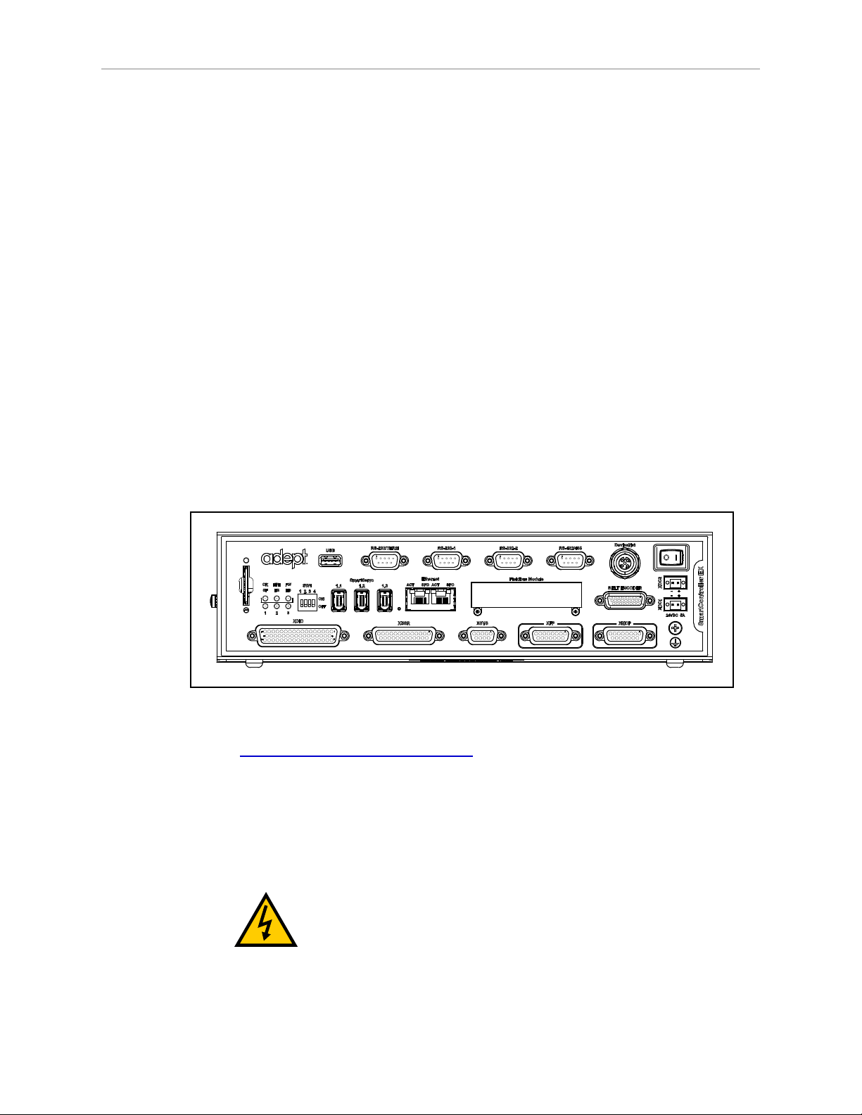
3.5 Robot Interface Panel
Chapter 3: System Installation
Figure 3-4. Robot Interface Panel
24 VDC—for connecting user-supplied 24 VDC power to the robot. The mating connector is
provided.
Ground Point—for connecting cable shield from user-supplied 24 VDC cable.
200-240 VAC—for connecting 200-240 VAC, single-phase, input power to the robot. The
mating connector is provided.
XIO (DB26, high density, female) — for user I/O signals for peripheral devices. This connector
provides 8 outputs and 12 inputs. For connector pin allocations for inputs and outputs, see
Using Digital I/O on eAIB XIO Connector on page 69. That section also contains details on
how to access these I/O signals via eV+.
XBELTIO — adds a belt encoder, EXPIO, (which supports either IOBLOX or an Intelligent
Force sensor), and an RS-232 interface. Requires optional eAIB XBELT IO Adapter cable. The
belt encoder can be split for two belts with a Y-adapter.
SmartServo x2 (IEEE 1394) — for connecting the IEEE 1394 cable from the robot to a controller.
The other robot connector can be used to connect to a second robot or another 1394-based
motion axis.
XSYSTEM — This requires either the eAIB XSYSTEM (three-headed)cable (XFP, XMCP, and
XUSR), or an eAIB XSYS cable, if connecting to a SmartController EX.
Adept Hornet 565 Robot User's Guide, User’s Guide, Rev A
Page 45 of 142
Page 42

Chapter 3: System Installation
ENET - Two Ethernet ports are available. One will be needed to connect to a PC running
Adept ACE software.
3.6 Connecting 24 VDC Power to Robot
Specifications for 24 VDC Robot and Controller Power
Table 3-1. VDC User-Supplied Power Supply
User-Supplied Power Supply 24 VDC (± 10%), 150 W (6 A)
Circuit Protection
Power Cabling 1.5 – 1.85 mm² (16-14 AWG)
Shield Termination Braided shield connected to ground at
a
User-supplied 24 VDC power supply must incorporate overload protection to limit
peak power to less than 300 W, or an 8 A in-line fuse must be added to the 24 VDC
power source. (In case of multiple robots on a common 24 VDC supply, each robot
must be fused individually.)
a
(21.6 V< Vin< 26.4 V)
Output must be < 300 W peak, or
8 Amp in-line fuse
both ends of cable. See User-Supplied 24
VDC Cable on page 48.
NOTE:Fuse information is located on the eAIB electronics.
The requirements for the user-supplied power supply will vary depending on the
configuration of the robot and connected devices. Adept recommends a 24 VDC, 6 A power
supply to allow for startup current draw and load from connected user devices, such as
solenoids and digital I/O loads. If multiple robots are to be sourced from a common 24 VDC
power supply, increase the supply capacity by 3 A for each additional robot.
CAUTION:Make sure you select a 24 VDC power supply that
meets the specifications in the preceding table. Using an
underrated supply can cause system problems and prevent
your equipment from operating correctly. See the following
table for recommended power supplies.
Table 3-2. Recommended 24 VDC Power Supplies
Vendor Name Model Ratings
XP Power JPM160PS24 24 VDC, 6.7 A, 160 W
Mean Well SP-150-24 24 VDC, 6.3 A, 150 W
Astrodyne ASM150-24 24 VDC, 6.66 A, 150 W
Adept Hornet 565 Robot User's Guide, User’s Guide, Rev A
Page 46 of 142
Page 43

Chapter 3: System Installation
Details for 24 VDC Mating Connector
The 24 VDC mating connector and two pins are supplied with each system. They are shipped
in the cable/accessories box.
Table 3-3. 24 VDC Mating Connector Specs
Connector Details Connector receptacle, 2 position, type:
Molex Saber, 18 A, 2-Pin
Molex P/N 44441-2002
Digi-Key P/N WM18463-ND
Pin Details Molex connector crimp terminal,
female, 14-18 AWG
Molex P/N 43375-0001
Digi-Key P/N WM18493-ND
Recommended crimping tools: Molex P/N 63811-7200
Digi-Key P/N WM1618-ND
Procedure for Creating 24 VDC Cable
NOTE:The 24 VDC cable is not supplied with the system, but is available in the
optional Power Cable kit. See List of Cables and Parts on page 36.
1.
Locate the connector and pins shown in the preceding table.
2.
Use 14-16 AWG wire to create the 24 VDC cable. Select the wire length to safely reach
from the user-supplied 24 VDC power supply to the robot base.
NOTE:A separate 24 VDC cable is required for the optional SmartController EX.
That cable uses a different style of connector. See the Adept SmartController EX User’s
Guide.
3.
Crimp the pins onto the wires using the crimping tool.
4.
Insert the pins into the connector. Confirm that the 24 VDC and ground wires are in the
correct terminals in the plug.
5.
Prepare the opposite end of the cable for connection to your user-supplied 24VDC
power supply.
Adept Hornet 565 Robot User's Guide, User’s Guide, Rev A
Page 47 of 142
Page 44

Chapter 3: System Installation
–
+
24 V, 6 A
Frame Ground
24 V, 5 A
–
+
User-Supplied
Power Supply
24 VDC
Adept Hornet
565 Robot
User-Supplied Shielded
Power Cable
-
+
SmartController EX
(Option)
User-Supplied Shielded
Power Cable
Attach shield from user-supplied
cable to side of controller using
star washer and M3 x 6 screw.
Attach shield from usersupplied cables to frame
ground on power supply.
Attach shield from usersupplied cable to ground
screw on robot interface
panel.
–
GND
+
Installing 24 VDC Robot Cable
1.
Connect one end of the shielded 24 VDC cable to the user-supplied 24 VDC power
supply. See the following figure.
l
The cable shield should be connected to frame ground on the power supply.
l
Do not turn on the 24 VDC power until instructed to do so in System Operation
on page 63.
2.
Plug the mating connector end of the 24 VDC cable into the 24 VDC connector on the
interface panel on the top of the robot.
3.
Connect the cable shield to the ground point on the interface panel.
Figure 3-5. User-Supplied 24 VDC Cable
NOTE:Adept recommends that DC power be delivered over a shielded cable, with
the shield connected to ground at both ends of the cable.
Adept Hornet 565 Robot User's Guide, User’s Guide, Rev A
Page 48 of 142
Page 45

Chapter 3: System Installation
3.7 Connecting 200-240 VAC Power to Robot
WARNING:Appropriately-sized branch circuit protection and
lockout/tagout capability must be provided in accordance with
the National Electrical Code and any local codes.
Ensure compliance with all local and national safety and
electrical codes for the installation and operation of the robot
system.
Specifications for AC Power
Table 3-4. Specifications for 200-240 VAC User-Supplied Power Supply
Auto-Ranging
Nominal
Voltage
200 to 240 V 180 V 264 V 50/60 Hz
Minimum
Operating
Voltage
a
Maximum
Operating
Voltage
Frequency/
Phasing
External Circuit
Breaker,
User-Supplied
10 Amps
1-phase
a
Specifications are established at nominal line voltage. Low line voltage can affect
robot performance.
NOTE:The Adept robot system is intended to be installed as a piece of equipment
in a permanently-installed system.
NOTE: If a three-phase power source is used, it must be symmetrically-earthed
(with grounded neutral). Connections called out as single-phase can be wired Line-
to-Neutral or Line-to-Line.
WARNING:Adept systems require an isolating transformer
for connection to mains systems that are asymmetrical or use
an isolated (impedant) neutral.
Many parts of Europe use an impedant neutral.
DANGER:AC power installation must be performed by a
skilled and instructed person - see the Adept Robot Safety Guide.
During installation, unauthorized third parties must be
prevented, through the use of fail-safe lockout measures, from
turning on power.
Facility Overvoltage Protection
The robot must be protected from excessive overvoltages and voltage spikes. If the country of
installation requires a CE-certified installation or compliance with IEC1131-2, the following
information may be helpful. IEC 1131-2 requires that the installation must ensure that
Adept Hornet 565 Robot User's Guide, User’s Guide, Rev A
Page 49 of 142
Page 46

Chapter 3: System Installation
EENNL
L
F1 10 A
Adept Hornet
565 Robot
1Ø 200–240 VAC
User-Supplied
AC Power Cable
Note: F1 is user-supplied, must be slow-blow.
1Ø
200–240 VAC
20 A
L = Line
N = Neutral
E = Earth Ground
EENL3L
L1
L2
F5 10 A
F4 10 A
Adept Hornet
565 Robot
1Ø 200–240 VAC
User-Supplied
AC Power Cable
Note: F4 and F5 are user-supplied, must be slow-blow.
3Ø
200–240 VAC
L = Line 1
N = Line 2
E = Earth Ground
200–240 VAC
CategoryII overvoltages (i.e., line spikes not directly due to lightning strikes) are not exceeded.
Transient overvoltages at the point of connection to the power source shall be controlled not to
exceed overvoltage CategoryII, i.e., not higher than the impulse voltage corresponding to the
rated voltage for the basic insulation. The user-supplied equipment or transient suppressor
shall be capable of absorbing the energy in the transient.
In the industrial environment, non-periodic overvoltage peaks may appear on mains power
supply lines as a result of power interruptions to high-energy equipment (such as a blown fuse
on one branch in a 3-phase system). This will cause high current pulses at relatively low
voltage levels. Take the necessary steps to prevent damage to the robot system (for example, by
interposing a transformer). See IEC 1131-4 for additional information.
AC Power Diagrams
Figure 3-6. Typical AC Power Installation with Single-Phase Supply
Figure 3-7. Single-Phase Load across L1 and L2 of a Three-Phase Supply
Adept Hornet 565 Robot User's Guide, User’s Guide, Rev A
Page 50 of 142
Page 47

Chapter 3: System Installation
Details for AC Mating Connector
The AC mating connector is supplied with each system. It is shipped in the Robot Accessory
Kit. The plug is internally labeled for the AC power connections (L, E, N).
Table 3-5. AC Mating Connector Details
AC Connector details AC in-line power plug,
straight, female, screw
terminal, 10 A, 250 VAC
Qualtek P/N 709-00/00
Digi-Key P/N Q217-ND
NOTE:The AC power cable is not supplied with the system. However, it is
available in the optional Power Cable kit. See List of Cables and Parts on page 36.
Procedure for Creating 200-240 VAC Cable
1.
Locate the AC mating connector shown in AC Mating Connector Details on page 51.
2.
Open the connector by unscrewing the screw on the shell and removing the cover.
3.
Loosen the two screws on the cable clamp. See AC Power Mating Connector on page 52.
4.
Use 18 AWG wire to create the AC power cable. Select the wire length to safely reach
from the user-supplied AC power source to the robot base.
5.
Strip 18 to 24 mm insulation from each of the three wires.
6.
Insert the wires into the connector through the removable bushing.
7.
Connect each wire to the correct terminal screw and tighten the screw firmly.
8.
Tighten the screws on the cable clamp.
9.
Reinstall the cover and tighten the screw to secure the connector.
10.
Prepare the opposite end of the cable for connection to the facility AC power source.
Adept Hornet 565 Robot User's Guide, User’s Guide, Rev A
Page 51 of 142
Page 48

Chapter 3: System Installation
Figure 3-8. AC Power Mating Connector
Installing AC Power Cable to Robot
1.
Connect the AC power cable to your facility AC power source.
Do not turn on AC power at this time.
See Typical AC Power Installation with Single-Phase Supply on page 50 and SinglePhase Load across L1 and L2 of a Three-Phase Supply on page 50.
2.
Plug the AC connector into the AC power connector on the interface panel on the robot.
3.
Secure the AC connector with the locking latch.
3.8 Grounding the Adept Robot System
Proper grounding is essential for safe and reliable robot operation.
Grounding Robot-Mounted Equipment
DANGER:Failing to ground robot-mounted equipment or
tooling that uses hazardous voltages could lead to injury or
death of a person touching the end-effector when an electrical
fault condition exists.
If hazardous voltages are present at any user-supplied robot-mounted equipment or tooling,
you must install a ground connection for that equipment or tooling. Hazardous voltages can
be considered anything in excess of 30 VAC (42.4 VAC peak) or 60VDC.
If there will be hazardous voltages present at the tool flange or end-effector, you must:
l
Connect the mounting frame to protective earth ground.
l
Ground the robot base to the mounting frame.
The eAIB is grounded to the robot base through a conductive gasket.
l
Ground the end-effector to the robot base.
Adept Hornet 565 Robot User's Guide, User’s Guide, Rev A
Page 52 of 142
Page 49

Chapter 3: System Installation
Frame
If frame is painted under screw head.
Use ring terminal and run the other
end to an unpainted part of the frame.
If frame is unpainted under screw head.
Use star washer, but not ring terminal.
Both screws and
star washers must
be electrically
conductive
(stainless or zincplated steel)
M12 Screw
External-tooth
star washer
Robot Base
NOTE:A ground strap from the end-effector to the base mounting pad must
include a service loop that allows full rotation and movement of the tool flange.
Grounding Robot Base to Frame
NOTE:You must ground the robot to the frame for all installations.
l
Use any of the three M12 mounting screws for this connection.
Screws must be stainless or zinc-plated steel.
l
Use an external-tooth star washer, touching the mounting screw head.
Washers must be stainless or zinc-plated steel.
If the frame is painted where the M12 screw makes contact with it, use a ring terminal under
the star washer, and connect the other end of the wire from the terminal to a suitable
grounding surface on the frame.
If the frame is not painted where the M12 screw makes contact with it, you do not need to use
a ring terminal, just put an external-tooth star washer under the mounting screw head.
3.9 Installing User-Supplied Safety Equipment
Figure 3-9. Any of the Three M12 Mounting Screws can be used for Grounding.
The user is responsible for installing safety barriers to protect personnel from coming in
contact with the robot unintentionally. Depending on the design of the workcell, safety gates,
light curtains, and emergency stop devices can be used to create a safe environment. Read the
Adept Robot Safety Guide for a discussion of safety issues.
Adept Hornet 565 Robot User's Guide, User’s Guide, Rev A
Page 53 of 142
Page 50

Chapter 3: System Installation
Refer to the Adept SmartController EX User's Guide for information on connecting safety
equipment into the system through the XUSR connector on the optional SmartController. There
is a detailed section on Emergency Stop Circuits and diagrams on recommended E-Stop
configurations.
The user-supplied safety and power-control equipment connects to the system through the
XUSR and XFP connectors, either on the eAIB XSYSTEM cable or the optional SmartController
EX. The XUSR connector (25-pin) and XFP (15-pin) connector are both female D-sub
connectors. Refer to the following table for the XUSR pin-out descriptions. See Table 3-7. for the
XFP pin-out descriptions. See the figure E-Stop Circuit on XUSR and XFP Connectors on page
57 for the XUSR wiring diagram.
Table 3-6. Contacts Provided by the XUSR Connector
Pin
Pairs
Description Comments
Voltage-Free Contacts Provided by Customer
1, 14 User E-Stop CH 1 (mushroom push-
N/C contacts, Shorted if NOT Used
button, safety gates, etc.)
2, 15 User E-Stop CH 2 (same as pins
N/C contacts, Shorted if NOT Used
1, 14)
3, 16 Line E-Stop (used for other robot or
N/C contacts, Shorted if NOT Used
assembly line E-Stop interconnection.
Does not affect E-Stop indication
(pins 7, 20)
4, 17 Line E-Stop (same as pins 3, 16) N/C contacts, Shorted if NOT Used
5, 18 Muted safety gate CH 1 (causes E-
N/C contacts, Shorted if NOT Used
Stop in Automatic mode only)
6, 19 Muted Safety Gate CH 2 (same as
N/C contacts, Shorted if NOT Used
pins 5, 18)
Voltage-Free Contacts provided by Adept
7, 20 E-Stop indication CH 1 Contacts are closed when Front Panel,
pendant, and customer E-Stops are not
tripped
8, 21 E-Stop indication CH 2 (same as pins
7, 20)
Contacts are closed when Front Panel,
pendant, and customer E-Stops are not
tripped
9, 22 Manual/Automatic indication CH 1 Contacts are closed in Automatic mode
10, 23 Manual/Automatic indication CH 2 Contacts are closed in Automatic mode
11, 12,
No connection
13, 24,
25
Adept Hornet 565 Robot User's Guide, User’s Guide, Rev A
Page 54 of 142
Page 51

Chapter 3: System Installation
Pin 1
Pin 8
Pin 9
Pin 15
XFP
Table 3-7. Contacts Provided by the XFP Connector
Pin
Pairs
Description Requirements for User-Supplied
Front Panel
Voltage-Free Contacts Provided by Customer
1, 9 Front Panel E-Stop CH 1 User must supply N/C contacts
2, 10 Front Panel E-Stop CH 2 User must supply N/C contacts
3, 11 Remote Manual/Automatic switch CH
1.
Optional - jumper closed for Auto
Mode-only operation
Manual = Open Automatic = Closed
4, 12 Remote Manual/Automatic switch CH
2.
Optional - jumper closed for Auto
Mode-only operation
Manual = Open Automatic = Closed
6, 14 Remote High Power on/off momentary
push-button
User must supply momentary pushbutton to enable High Power to system
Non-voltage-Free Contacts
5, 13 Adept Supplied 5 VDC and GND for
High Power On/Off Switch Lamp
User must supply lamp, or use 1 W,
47 ohm resistor - system will not
operate if not present
a
7, 15
Controller system 5 V power on LED, 5
Optional - indicator only
V, 20mA
8 No connection
See the figure Front Panel Schematic on page 58 for a schematic diagram of the Adept Front
Panel.
a
Users must exercise caution to avoid inadvertently connecting 24 V signals to these pins,
because this will damage the electronics.
NOTE:The system was evaluated by Underwriters Laboratory with an Adept Front
Panel. If you provide a substitute front panel, this could void UL compliance.
Adept Hornet 565 Robot User's Guide, User’s Guide, Rev A
Page 55 of 142
Page 52

Chapter 3: System Installation
Table 3-8. Remote Pendant Connections on the XMCP Connector
Pin XMCP
(15-Pin D-Sub)
Description
1, 9 Pendant E-Stop Push-button CH 1
2, 10 Pendant E-Stop Push-button CH 2
3, 11 Pendant Enable CH 1 (Hold-to-run)
4, 12 Pendant Enable CH 2 (Hold-to-run)
13 Serial GND/Logic GND
7 Pendant TXD: eV+to Pendant TXD
8 Pendant RXD: eV+to Pendant RXD
14 No connection
15 No connection
Shield Shield GND
6 24 V
5 No connection
The following figure shows an E-Stop diagram for the system. See System Installation on page
35 for a description of the functionality of this circuit.
Adept Hornet 565 Robot User's Guide, User’s Guide, Rev A
Page 56 of 142
Page 53

Chapter 3: System Installation
ES1
ES2
ESTOP 24 V
Source
XSYSTEM-31
(XFP-1)
XSYSTEM-20
(XFP-9)
(XPND-7)
XSYSTEM-24
(XPND-24)
(XUSR-1)
(XUSR-14)
XSYSTEM-13
(XUSR-3)
(XPND-9)
T20 Pendant
Enable
XSYSTEM-8
(XPND-26)
Manual Mode
Path
Force-Guided Relay
Cyclic Check
Control Circuit
Single-Phase
AC Input
200-240 VAC
Front Panel
ESTOP
Pushbutton
T20 ESTOP
Pushbutton
User E-Stop and Gate Interlock
(Jumper closed when not used,
MUST open both channels
independently if used.)
LINE E-Stop (External
User E-Stop System)
Muted Safety Gate Active in Auto mode only
(Jumper closed when
not used)
Front Panel
Auto/Manual
Keyswitch
High Power to
Amplifiers
(Internal Connections)
Front Panel
High Power
ON/OFF
Auto/Manual
Output
User ESTOP
Output
XSYSTEM-32
(XFP-2)
ESTOP
Ground
(XFP-10)
(XPND-6)
(XPND-23)
(XUSR-2)
(XUSR-15)
XSYSTEM-43
(XUSR-4)
XSYSTEM-39 (XUSR-17)
XSYSTEM-9 (XUSR-16)
(XPND-8)
XSYSTEM-38
(XPND-25)
XSYSTEM-29 (XUSR-18)
XSYSTEM-44 (XUSR-19)
ES1
ES2
SR1 SR2
AM2
AM1
XSYSTEM-14
(XUSR-5)
XSYSTEM-30
(XUSR-6)
Auto Mode
Path
XSYSTEM-33 (XFP-13)
6 V, 1.2 W
Bulb
XSYSTEM-3 (XFP-5)
XSYSTEM-31 (XFP-6)
XSYSTEM-34 (XFP-14)
ESTOP 24 V
Source
XSYSTEM-5
(XFP-4)(XFP-3)
XSYSTEM-19
(XFP-12)
XSYSTEM-4
(XFP-11)
AM2
Coil
AM1
Coil
XSYSTEM-12 (XUSR-9)
XSYSTEM-28 (XUSR-10)
AM2
AM1
XSYSTEM-42 (XUSR-23)
XSYSTEM-27 (XUSR-22)
XSYSTEM-26 (XUSR-8)
XSYSTEM-10 (XUSR-7)
XSYSTEM-25 (XUSR-20)
XSYSTEM-40 (XUSR-21)
Figure 3-10. E-Stop Circuit on XUSR and XFP Connectors
Adept Hornet 565 Robot User's Guide, User’s Guide, Rev A
Page 57 of 142
Page 54

Chapter 3: System Installation
ESTOPSRC
24 VS
5 VD
D
SYSPWRLT 7
6
5
4
2
3
1
17
16
8
10
9
11
12
13
14
15
XFP
15PDSUBM
MANUALSRC1
HIPWRREQ
MANUALRLY2
MANUALRLY1
HIPWRLT
ESTOPFP2
ESTOPFP1
HPLT5V
NC
MANUALSRC2
"MANUAL/AUTO""System Power LED"
MANUALSRC1
SW1
MANUALRLY2
MANUALRLY1
MANUALSRC2
24 VS
"HIGH POWER ON/OFF"
SWL1
HIPWRREQ
HPLT5 V
HIPWRLT
D
ESTOPSRC
"EMERGENCY STOP"
SW2
ESTOPFP2
ESTOPFP1
5 VD
D
2-PIN_MINI
SYSPWRLT
Adept Front Panel Schematic
Figure 3-11. Front Panel Schematic
Emergency Stop Circuits
The eAIB XSYSTEM cable provides connections for Emergency Stop (E-Stop) circuits on the
XUSR and XFP connectors. This gives the controller system the ability to duplicate E-Stop
functionality from a remote location using voltage-free contacts. See Figure 3-10.
The XUSR connector provides external two-channel E-Stop input on pin pairs 1, 14 and 2, 15.
The XFP connector provides two-channel E-Stop input on pin pairs 1, 9 and 2, 10.
NOTE:These pins must be shorted if not used. Both channels must open
independently if used. Although an Emergency Stop will occur, the controller will
flag an error state if one channel is jumpered closed and the other channel is
opened. It will also flag an error state if the channels are shorted together.
User E-Stop Indication Contacts - Remote Sensing of E-Stop
These contacts provide a method to indicate the status of the ESTOP chain, inclusive of the
Front Panel Emergency Stop push-button, the pendant Emergency Stop push-button, and the
User Emergency Stop Contacts.
NOTE:These contacts do not indicate the status of any connections below the User
E-Stop contacts. Thus, they will NOT indicate the status of the Line E-Stop, MCP
Adept Hornet 565 Robot User's Guide, User’s Guide, Rev A
Page 58 of 142
Page 55

Chapter 3: System Installation
ENABLE, or the Muted Safety gate. If you have a specific need in this area, contact
Adept Customer Service for information on alternate indicating modes.
Two pairs of pins on the XUSR connector (pins 7, 20 and 8, 21) provide voltage-free contacts,
one for each channel, to indicate whether the E-Stop chain, as described above, on that channel
is closed. Both switches are closed on each of the redundant circuits in normal operation (no
E-Stop). The user may use these contacts to generate an E-Stop for other equipment in the
workcell. The load on the contacts must not exceed 40 VDC or 30VAC at a maximum of 1 A.
These voltage-free contacts are provided by a redundant, cyclically-checked, positive-drive,
safety relay circuit for Category 3 PL-d per ENISO 13849 operation (see Figure 3-10. and the
table System Installation on page 35 for the customer E-Stop circuitry).
Line E-Stop Input
The XUSR connector on the controller contains a two-channel Line E-Stop input for workcell or
other equipment emergency-stop inputs. Generally, the customer E-Stop Indication contact
outputs are used to generate an emergency stop in such external equipment. Thus, if one were
to wire the same equipment’s outputs into the customer E-Stop input (that is, in series with the
local robot’s E-Stop push-buttons), a lock-up situation could occur.
The Line E-Stop input comes into the circuit at a point where it cannot affect the customer EStop indication relays and will not cause such a lock-up situation. For any situation where two
systems should be cross-coupled, for example, the customer E-Stop indication of one controller
is to be connected to the input of another controller, the Line E-Stop input is the point to bring
in the other controller’s output contacts. See the figure E-Stop Circuit on XUSR and XFP
Connectors on page 57 for more information.
Do not use the Line E-Stop for such devices as local E-Stop push-buttons, since their status
should be reported to the outside on the local user E-Stop indication output contact while the
Line E-Stop inputs will not.
Muted Safety Gate E-Stop Circuitry
Two pairs of pins on the XUSR connector (pins 5, 18 and 6, 19) provide connections for a
safety gate designed to yield an E-Stop allowing access to the workspace of the robot in
Manual mode only, not in Automatic mode. It is up to the customer to determine if teaching
the robot in Manual Mode, by a skilled programmer (See Qualification of Personnel in the
Adept Robot Safety Guide), wearing safety equipment and carrying an Adept pendant, is
allowable under local regulations. The E-Stop is said to be “muted” in Manual mode (for the
customer E-Stop circuitry, see the figures and tables at the beginning of the section System
Installation on page 35).
The muted capability is useful for a situation where a shutdown must occur if the cell gate is
opened in Automatic mode, but you need to open the gate in Manual mode. If the mute gate is
opened in Automatic mode, the robot defaults to Manual mode operation when power is reenabled. In muted mode, the gate can be left open for personnel to work in the robot cell.
However, safety is maintained because of the speed restriction.
CAUTION:If you want the cell gate to always cause a robot shutdown,
wire the gate switch contacts in series with the user E-Stop inputs. Do not
wire the gate switch into the muted safety gate inputs.
Adept Hornet 565 Robot User's Guide, User’s Guide, Rev A
Page 59 of 142
Page 56

Chapter 3: System Installation
Remote Manual Mode
The optional Adept Front Panel provides for a Manual Mode circuit. See Remote High Power
On/Off Control on page 60 for further details about the customer Remote Manual Mode
circuitry.
The Adept Front Panel, or a user-supplied panel, must be incorporated into the robot workcell
to provide a “Single Point of Control” (the pendant) when the controller is placed in Manual
mode. Certain workcell devices, such as PLCs or conveyors, may need to be turned off when
the operating mode switch is set to Manual mode. This is to ensure that the robot controller
does not receive commands from devices other than from the pendant, the single point of
control.
If the user needs to control the Manual/Automatic mode selection from other control
equipment, then a custom splitter cable or complete replacement of the Adept Front Panel may
be required. See Front Panel Schematic on page 58. In this situation, a pair of contacts should
be wired in series with the Adept Front Panel Manual/Automatic mode contacts. Thus, both the
AdeptFront Panel, or the user-supplied panel, and the customer contacts need to be closed to
allow Automatic mode.
WARNING:Do not wire user-supplied Manual/Automatic contacts in
parallel with the Adept Front Panel, or the user-supplied panel, switch
contact. This would violate the “Single Point of Control” principle and
might allow Automatic (high-speed) mode to be selected while an
operator is in the cell.
User Manual/Auto Indication
Two pairs of pins on the XUSR connector (pins 9, 22 and 10, 23) provide a voltage-free
contact to indicate whether the Front Panel and/or remote Manual/Automatic switches are
closed. The user may use these contacts to control other mechanisms (for example, conveyor,
linear modules, etc.) when Manual mode is selected. The load on the contacts should not
exceed 40 VDC or 30 VAC at a maximum of 1 A.
User High Power On Indication
In the optional SmartController EX, eV+ controls a normally-open relay contact on the XDIO
connector (pins 45, 46, see the table System Installation on page 35), that will close when high
power has been enabled. The user can use this feature to power an indicator lamp or other
device, that signals High Power is On. The limit on these contacts is 1 A at 30 VDC or 30
VAC.
Remote High Power On/Off Control
The easiest and most effective way to provide the high power on/off control in a remote
location is to mount an optional Adept Front Panel in the desired location with an extension
cable.
However, if the user needs to control high power on/off from other control equipment or from
a location other than the front panel, then a custom splitter cable will be required. See the Front
Panel schematic (Front Panel Schematic on page 58) for details of the Adept Front Panel’s
wiring. In this situation, a second momentary contact for high power on/off would be placed in
Adept Hornet 565 Robot User's Guide, User’s Guide, Rev A
Page 60 of 142
Page 57

Chapter 3: System Installation
parallel with the panel push-button contact. This second contact should be suppressed when in
Manual mode (see the note on “Single Point of Control” below).
This method allows relocating the push-button switch to a more convenient location.
Implementation of this method must conform to EN standard recommendations.
NOTE:European standards require that the remote High Power push-button be
located outside of the workspace of the robot.
Pins 6, 14 and 5, 13 of the XFP connector provide this remote capability. Pins 5, 13 provide
power for the lamp, +5 VDC and ground, respectively. Pins 6, 14 are inputs for voltage-free
normally-open contacts from a user-supplied momentary push-button switch.
WARNING:To fulfill the “Single Point of Control” requirement, do not
place the Manual/Automatic and High Power On controls in multiple
locations. After putting the robot into Manual mode, the operator should
remove the key for safety purposes. The system should not be wired so
that a PLC or another operator can put the system back into Automatic
mode.
High Power On/Off Lamp
The Adept Front Panel High Power On/Off Lamp (P/N: 27400-29006) will cause an error, from
eV+, if the lamp burns out. This error prevents High Power from being turned on. This safety
feature prevents a user from not realizing that High Power is enabled because the High Power
indicator is burned out. See Changing the Lamp in the Optional Adept Front Panel HighPower Indicator on page 106 for information on changing this lamp.
Remote Front Panel or User-Supplied Control Panel Usage
Users can mount the optional Front Panel remotely by using an extension cable or by wiring a
user-supplied Front Panel (control panel) to the controller using the 15-pin XFP connector. The
Front Panel contains no active components, only switches and lights. Customers should be
able to adapt the Front Panel’s functionality into their own Front Panel design. To
automatically control the Front Panel’s signals, use relay contacts instead of switches. See the
figure Front Panel Schematic on page 58 for a schematic drawing of the Front Panel, and see
the table System Installation on page 35 for a summary of connections and pin numbers.
NOTE:The system was evaluated by Underwriters Laboratory with an Adept Front
Panel. If you provide a substitute front panel, the system may no longer be UL
compliant.
Customers can build an extension cable to place the optional Adept Front Panel in a remote
location. The extension cable must conform to the following specifications:
l
Wire Size: must be larger than 26 AWG.
l
Connectors: must be 15-pin, standard D-sub male and female.
l
Maximum cable length is 10 meters.
Adept Hornet 565 Robot User's Guide, User’s Guide, Rev A
Page 61 of 142
Page 58

Chapter 3: System Installation
NOTE: The XMCP and XFP connectors can be interchanged without electrical
damage. However, neither the Front Panel nor the pendant will work properly
unless they are plugged into the correct connector.
Remote Pendant Usage
Customers can build an extension cable to place the pendant in a remote location. The
extension cable must conform to the following specifications:
l
Wire Size: must be larger than 26 AWG.
l
Connectors: must be 15-pin, standard D-sub male and female.
l
Maximum cable length is 10 meters.
CAUTION:Do not modify the cable that is attached to the pendant. This
could cause unpredictable behavior from the robot system.
Adept Hornet 565 Robot User's Guide, User’s Guide, Rev A
Page 62 of 142
Page 59

Chapter 4: System Operation
4.1 Robot Status Display Panel
The robot Status Display panel is located on the side of the robot base.
The combined status LED/high-power lamp and the brake-release button are on the underside
of the robot base.
The Status Display and LED blinking pattern indicate the status of the robot.
Figure 4-1. Robot Status Display Panel
Table 4-1. Robot Status LED Definition
LED Status
Off No display 24 VDC not present
Off OK High Power Disabled
Amber, Solid ON High Power Enabled
Amber, Solid Fault Code(s) Fault, see Status Display
Amber, Slow Blink OK Selected Configuration Node
Amber, Fast Blink Fault Code(s) Fault, see Status Display
1
See Status Panel Fault Codes on page 64.
Adept Hornet 565 Robot User's Guide, User’s Guide, Rev A
2-Digit Status
Panel Display
Page 63 of 142
Description
1
1
Page 60

Chapter 4: System Operation
4.2 Status Panel Fault Codes
The Status Display, shown in Robot Status Display Panel on page 63, displays alpha-numeric
codes that indicate the operating status of the robot, including fault codes. The following table
gives definitions of the fault codes. These codes provide details for quickly isolating problems
during troubleshooting.
The displayed fault code will continue to be displayed even after the fault is corrected or
additional faults are recorded. All displayed faults are cleared from the display, and reset to a
no-fault condition, upon successfully enabling high power to the robot, or power cycling the 24
V supply to the robot.
LED Status Code LED Status Code
OK No Fault H# High Temp Encoder (Joint #)
ON High Power ON Status hV High Voltage Bus Fault
MA Manual Mode I# Initialization Stage (Step #)
24 24 V Supply Fault M# Motor Stalled (Joint #)
Table 4-2. Status Panel Codes
A# Amp Fault (Joint #) NV Non-Volatile Memory
B# IO Blox Fault (Address #) P# Power System Fault (Code #)
BA Backup Battery Low Voltage PR Processor Overloaded
AC AC Power Fault RC RSC Fault
D# Duty Cycle Exceeded (Joint #) S# Safety System Fault (Code #)
E# Encoder Fault (Joint #) SE E-Stop Delay Fault
ES E-Stop SW Watchdog Timeout
F# External Sensor Stop T# Safety System Fault (Code 10 + #)
FM Firmware Mismatch TR Teach Restrict Fault
FW IEEE 1394 Fault V# Hard Envelope Error (Joint #)
h# h# High Temp Amp (Joint #)
For more information on status codes, go to the Adept Document Library on the Adept website,
and in the Procedures, FAQs, and Troubleshooting section, look for the Adept Status Code
Summary document.
See Major Robot Components on page 11 for Joint # locations.
4.3 Using the Brake-Release Button
Robot Brakes
The robot has a braking system which decelerates the robot in an emergency condition, such
as when the emergency stop circuit is open or a robot joint passes its softstop.
Adept Hornet 565 Robot User's Guide, User’s Guide, Rev A
Page 64 of 142
Page 61

Chapter 4: System Operation
BrakeRelease
Button
Status Display
Panel
Joint 1
Joint 2
Joint 3
Status LED/
High-power
Lamp
This braking system does not prevent you from moving the robot manually, once the robot has
stopped (and high power has been disabled).
In addition, the three inner-arm motors have electromechanical brakes, which are released
when high power is enabled. When high power is disabled, the brakes engage and hold the
position of the platform fixed.
Brake-Release Button
Under some circumstances, you may want to manually position the platform without enabling
high power. For such instances, a Brake-Release button is located on the underside of the robot
base. When system power is ON, pressing this button releases the brakes, which allows
movement of the arms and platform.
Figure 4-2. Brake Release and LED Light
If this button is pressed while high power is ON, high power automatically shuts down.
NOTE:24 Volt robot power must be ON to release the brakes.
CAUTION:When the Brake-Release button is pressed, the
platform and end-effector may drop to the bottom of its travel.
To prevent possible damage to the equipment, make sure that
the platform is supported when releasing the brakes and verify
that the end-effector or other installed tooling is clear of all
obstructions.
Adept Hornet 565 Robot User's Guide, User’s Guide, Rev A
Page 65 of 142
Page 62

Chapter 4: System Operation
2
3
4
Auto
Mode
Manual
Mode
5
1
Remote Brake Release Feature
You can also configure the XIO Input 6.2 (pin 18) to act as an alternate hardware brake release
input. The setting is available on the Robot page in the Adept ACE software. The parameter is
Remote Brake Release Input. When enabled (True), activating XIO Input 6.2 is identical to
pressing the physical brake release button on the robot base. The input status will still reflect
in the IO register.
4.4 Optional Adept Front Panel
Figure 4-3. Adept Front Panel
1.
XFP cable
With a SmartController EX:Connects to the XFP connector on the SmartController.
Without a SmartController EX, connects to the XFP branch of the eAIBXSYSTEM cable.
2.
System 5 V Power-On LED
Indicates whether or not power is connected to the robot.
3.
Manual/Automatic Mode Switch
Switches between Manual and Automatic mode. In Automatic mode, executing
programs control the robot, and the robot can run at full speed. In Manual mode, the
system limits robot speed and torque so that an operator can safely work in the cell.
Manual mode initiates software restrictions on robot speed, commanding no more than
250 mm/sec.
4.
High Power On/Off Switch and Lamp
Controls high power, which is the flow of current to the robot motors. Enabling high
power is a two-step process. An “Enable Power” request must be sent from the usersupplied PC, an executing program, or the optional pendant. Once this request has been
made and the High Power On/Off lamp/button is blinking, the operator must press and
release this button, and high power will be enabled.
NOTE:The use of the blinking High Power button can be configured (or
eliminated) in software. Your system may not require this step.
Adept Hornet 565 Robot User's Guide, User’s Guide, Rev A
Page 66 of 142
Page 63

Chapter 4: System Operation
NOTE:If enabled, the Front Panel button must be pressed while blinking
(default time-out is 10 seconds). If the button stops blinking, you must enable
power again.
5.
Emergency Stop Switch
The E-Stop is a dual-channel, passive E-Stop that supports Category 3 CE safety
requirements. Pressing this button turns off high power to the robot motors.
NOTE:A Front Panel or equivalent circuits must be installed to be able to Enable
Power to the robot. To operate without the Adept Front Panel, the user must supply
the equivalent circuits.
4.5 Connecting Digital I/O to the System
You can connect digital I/O to the system in several different ways. See the following table and
figure.
I/O on the eAIB:
Table 4-3. Digital I/O Connection Options
Product I/O Capacity For more details
XIO Connector on eAIB 12 inputs
8 outputs
IOBlox, using
optional eAIB XBELT IO Adapter
Cable
12 inputs
8 outputs
see Using Digital I/O on eAIB
XIO Connector on page 69
Adept IO Blox User’s Guide
I/O with an Optional SmartController EX:
Table 4-4. More Digital I/O Connection Options
Product I/O Capacity For more details
XDIO Connector on
optional SmartController EX
Optional sDIO Module,
connects to SmartController EX
12 inputs
8 outputs
32 inputs, 32 outputs
per module; up to four
sDIO per system
see the Adept SmartController
EX User’s Guide
see the Adept SmartController
EX User’s Guide
Adept Hornet 565 Robot User's Guide, User’s Guide, Rev A
Page 67 of 142
Page 64

Chapter 4: System Operation
Optional
IO Blo
x
Device
IO Blox #1
8 Input signals: 1113 to 1120
8 Output signals: 0105 to 0112
eAIB XBELTIO
Adapter Cable
RS-232
XBEL
T
EXPIO
SF
IEEE-1394
X2
SC-DIO
LINK
*S/N 3563-XXXXX*
X1
24V 0.5A
R
OK
X4
-
+ - +
1.1
1.2
XDC1 XDC2
X3
DC
IN
24 V
GND
AC
200 -
240 V
Ø
1
XBELTIO
XIO
Servo
ENETENET
XSYSTEM
Optional
sDIO #1
Optional
SmartController EX
Hornet 565 Robot
XIO Connector
12 Input signals: 1097 to 1105
8 Output signals: 0097 to 0104
XDIO Connector
12 Input signals: 1001 to 1012
8 Output signals: 0001 to 0008
sDIO #1
32 Input signals: 1033 to 1064
32 Output signals: 0033 to 0064
For Dual Robot systems, see the Adept Dual-Robot Configuration Procedure.
Figure 4-4. Connecting Digital I/O to the System
Table 4-5. Default Digital I/O Signal Configuration, Single Robot System
Location Type Signal Range
Controller XDIO connector Inputs 1001 - 1012
Outputs 0001 - 0008
sDIO Module Inputs 1033 - 1064
Outputs 0033 - 0064
sDIO Module 2 Inputs 1065 - 1096
Robot 1 XIO connector Inputs 1097 - 1108
Outputs 0065 - 0096
Outputs 0097 - 0104
Adept Hornet 565 Robot User's Guide, User’s Guide, Rev A
Page 68 of 142
Page 65

Chapter 4: System Operation
Pin 1
Pin 9
Pin 10
Pin 18
Pin 26
Pin 19
4.6 Using Digital I/O on eAIB XIO Connector
The XIO connector on the robot interface panel offers access to digital I/O, 12 inputs and 8
outputs. These signals can be used by eV+ to perform various functions in the workcell.
See the following table for the XIO signal designations.
l
12 Inputs, signals 1097 to 1108
l
8 Outputs, signals 0097 to 0104
Brake Release and LED Light
Table 4-6. XIO Signal Designations, Inputs
Pin
No.
Designation
Signal
Bank
eV+
Signal
Number
1 GND
2 24 VDC
3 Common 1 1
4 Input 1.1 1 1097
5 Input 2.1 1 1098
6 Input 3.1 1 1099
7 Input 4.1 1 1100
8 Input 5.1 1 1101
9 Input 6.1 1 1102
10 GND
11 24 VDC
12 Common 2 2
13 Input 1.2 2 1103
Pin Locations
14 Input 2.2 2 1104
15 Input 3.2 2 1105
16 Input 4.2 2 1106
17 Input 5.2 2 1107
18 Input 6.2 2 1108
Adept Hornet 565 Robot User's Guide, User’s Guide, Rev A
Page 69 of 142
XIO 26-pin female
connector on Robot
Interface Panel
Page 66

Chapter 4: System Operation
Table 4-7. XIO Signal Designations, Outputs
Pin
No. Designation
Signal
Bank
eV+
Signal
Number
19 Output 1 0097
20 Output 2 0098
21 Output 3 0099
22 Output 4 0100
23 Output 5 0101
24 Output 6 0102
25 Output 7 0103
26 Output 8 0104
Optional I/O Products
These optional products are also available for use with digital I/O:
l
XIO Breakout Cable, 5 meters long, with flying leads on user’s end. See XIO Breakout
Cable on page 74 for information. This cable is not compatible with the XIO
Termination Block.
Pin Locations
l
XIO Termination Block, with terminals for user wiring, plus input and output status
LEDs. Connects to the XIO connector with 6-foot cable. See the Adept XIO Termination
Block Installation Guide for details.
XIO Input Signals
The 12 input channels are arranged in two banks of 6. Each bank is electrically isolated from
the other bank and is optically isolated from the robot’s ground. The 6 inputs within each
bank share a common source/sink line.
The inputs are accessed through direct connection to the XIO connector (see Table 4-6. ), or
through the optional XIO Termination Block. See the documentation supplied with the
Termination Block for details.
The XIO inputs cannot be used for REACTI programming, high-speed interrupts, or vision
triggers. See the eV+ Language User’s Guide for information on digital I/O programming.
XIO Input Specifications
Table 4-8. XIO Input Specifications
Operational voltage range 0 to 30 VDC
OFF state voltage range 0 to 3 VDC
ON state voltage range 10 to 30 VDC
Adept Hornet 565 Robot User's Guide, User’s Guide, Rev A
Page 70 of 142
Page 67

Chapter 4: System Operation
Typical threshold voltage Vin= 8 VDC
Operational current range 0 to 7.5 mA
OFF state current range 0 to 0.5 mA
ON state current range 2.5 to 7.5 mA
Typical threshold current 2.0 mA
Impedance (Vin/Iin) 3.9 KΩ minimum
Current at Vin= +24 VDC Iin≤ 6 mA
Turn-on response time (hardware)
Software scan rate/response time
5 µsec maximum
16 ms scan cycle/
32 ms max response time
Turn-off response time (hardware)
Software scan rate/response time
5 µsec maximum
16 ms scan cycle/
32 ms max response time
NOTE:The input current specifications are provided for reference. Voltage sources
are typically used to drive the inputs.
Adept Hornet 565 Robot User's Guide, User’s Guide, Rev A
Page 71 of 142
Page 68

Typical Input Wiring Example
Adept-Supplied Equipment
User-Supplied Equipment
Signal 1097
Part Present Sensor
4
Signal 1098
Feeder Empty Sensor
5
Signal 1099
Part Jammed Sensor
6
Signal 1100
Sealant Ready Sensor
7
Signal 1101
8
Signal 1102
+24V
GND
9
Bank 1
Common
Bank 2
Common
3
2
1
Signal 1103
13
Signal 1104
14
Signal 1105
15
Signal 1106
16
Signal 1107
17
Signal 1108
18
12
GND
10
+24V
11
Wiring
Terminal
Block
Typical User
Input Signals
Note: all Input signals
can be used for either
sinking or sourcing
configurations.
Bank 1 configured for
Sinking (NPN) Inputs
Bank 2 configured for
Sourcing (PNP) Inputs
Input Bank 2 Input Bank 1
XIO Connector – 26-Pin Female D-Sub
(equivalent circuit)
Chapter 4: System Operation
XIO Output Signals
The eight digital outputs share a common, high side (sourcing) driver IC. The driver is
designed to supply any kind of load with one side connected to ground. It is designed for a
range of user-provided voltages, from 10 to 24 VDC, and each channel is capable of up to 0.7
A of current. This driver has overtemperature protection, current limiting, and shorted-load
protection. In the event of an output short or other overcurrent situation, the affected output of
Figure 4-5. Typical User Wiring for XIO Input Signals
NOTE:The OFF state current range exceeds the leakage current of XIO outputs. This
guarantees that the inputs will not be turned on by the leakage current from the
outputs. This is useful in situations where the outputs are looped-back to the inputs
for monitoring purposes.
Adept Hornet 565 Robot User's Guide, User’s Guide, Rev A
Page 72 of 142
Page 69

Chapter 4: System Operation
the driver IC turns off and back on automatically to reduce the temperature of the IC. The
driver draws power from the primary 24 VDC input to the robot through a self-resetting
polyfuse.
The outputs are accessed through a direct connection to the XIO connector (see XIO Signal
Designations, Inputs on page 69), or through the optional XIO Termination Block. See the
documentation supplied with the Termination Block for details.
XIO Output Specifications
Table 4-9. XIO Output Circuit Specifications
Parameter Value
Power supply voltage range See System Installation on page 35.
Operational current range,
per channel
Total Current Limitation,
all channels on
ON-state resistance (I
= 0.5 A) Ron≤ 0.32 Ω @ 85° C
out
Output leakage current I
I
≤ 700 mA
out
I
≤ 1.0 A @ 40° C ambient
total
I
≤ 1.5 A @ 25° C ambient
total
≤ 25 µA
out
Turn-on response time 125 µsec max., 80 µsec typical
(hardware only)
Turn-off response time 60 µsec. max., 28 µsec typical
(hardware only)
Output voltage at inductive load turnoff (I
Load = 1 mH)
DC short circuit current limit 0.7 A ≤ I
Peak short circuit current I
out
= 0.5 A,
(+V - 65) ≤V
LIM
≤ 4 A
ovpk
demag
≤ 2.5 A
≤ (+V - 45)
Adept Hornet 565 Robot User's Guide, User’s Guide, Rev A
Page 73 of 142
Page 70

Chapter 4: System Operation
M
Adept-Supplied Equipment User-Supplied Equipment
Outputs 1-8
Typical User Loads
XIO Connector – 26-Pin Female D-Sub
+24 VDC
19
Signal 0097
20
Signal 0098
21
Signal 0099
22
Signal 0100
23
Signal 0101
24
Signal 0102
25
Signal 0103
26
Signal 0104
GND
GND
Load
1
Customer
AC Power
Supply
10
M
Load
Load
L
N
(equivalent
circuit)
Wiring
Terminal
Block
Typical Output Wiring Example
Figure 4-6. Typical User Wiring for XIO Output Signals
XIO Breakout Cable
The XIO Breakout cable is available as an option—see the following figure. This cable connects
to the XIO connector on the eAIB, and provides flying leads on the user’s end, for connecting
input and output signals in the workcell. The cable length is 5 M (16.4 ft).
See the following table for the cable wire chart.
NOTE:This cable is not compatible with the XIO Termination Block.
Adept Hornet 565 Robot User's Guide, User’s Guide, Rev A
Figure 4-7. Optional XIO Breakout Cable
Page 74 of 142
Page 71

Chapter 4: System Operation
Pin 9
Pin 1
Pin 18
Pin 10
Pin 19
Pin 26
Table 4-10. XIO Breakout Cable Wire Chart
Signal
Pin No.
Designation Wire Color Pin Locations
1 GND White
2 24 VDC White/Black
3 Common 1 Red
4 Input 1.1 Red/Black
5 Input 2.1 Yellow
6 Input 3.1 Yellow/Black
7 Input 4.1 Green
8 Input 5.1 Green/Black
9 Input 6.1 Blue
10 GND Blue/White
11 24 VDC Brown
12 Common 2 Brown/White
13 Input 1.2 Orange
14 Input 2.2 Orange/Black
15 Input 3.2 Grey
16 Input 4.2 Grey/Black
17 Input 5.2 Violet
18 Input 6.2 Violet/White
19 Output 1 Pink
20 Output 2 Pink/Black
21 Output 3 Light Blue
22 Output 4 Light Blue/Black
23 Output 5 Light Green
24 Output 6 Light Green/Black
25 Output 7 White/Red
26-pin male
connector on XIO
Breakout Cable
26 Output 8 White/Blue
Shell Shield
Adept Hornet 565 Robot User's Guide, User’s Guide, Rev A
Page 75 of 142
Page 72

Chapter 4: System Operation
4.7 Starting the System for the First Time
Follow the steps in this section to safely bring up your robot system. The tasks include:
l
Verifying installation, to confirm that all tasks have been performed correctly
l
Starting up the system by turning on power for the first time
l
Verifying that all E-Stops in the system function correctly
l
Moving the robot with the pendant (if purchased), to confirm that each joint moves
correctly
Verifying Installation
Verifying that the system is correctly installed and that all safety equipment is working
correctly is an important process. Before using the robot, perform the following checks to
ensure that the robot and controller have been properly installed.
DANGER:After installing the robot, you must test it before
you use it for the first time. Failure to do this could cause
death, serious injury, or equipment damage.
Mechanical Checks
l
Verify that the robot is mounted level and that all fasteners are properly installed and
tightened.
l
Verify that any platform tooling is properly installed.
l
Verify that the platform has been aligned with the J4 motor (J4 version only).
l
Verify that all peripheral equipment is properly installed such that it is safe to turn on
power to the robot system.
System Cable Checks
Verify the following connections:
NOTE:The first three connections are made via the eAIB XSYSTEM cable if you are
not using an optional SmartController EX.
l
Front Panel to the XSYSTEM on the eAIB, or
XFP port on a SmartController EX.
l
Pendant to the XSYSTEM on the eAIB, or
XMCP port on a SmartController EX, or a loop-back dongle installed.
l
XUSR to the XSYSTEM on the eAIB, or
XUSR port on a SmartController EX,
or XUSR jumper installed.
l
User-supplied 200/240 VAC power to the robot 200/240 VAC connector.
Adept Hornet 565 Robot User's Guide, User’s Guide, Rev A
Page 76 of 142
Page 73

Chapter 4: System Operation
l
User-supplied 24 VDC power to the robot 24 VDC connector.
l
Ethernet cable from PLC (if used) to eAIB or SmartController EX (if used)
If you are using an optional SmartController EX:
l
User-supplied 24 VDC power connected to the SmartController.
l
User-supplied ground wire installed between the SmartController and ground.
l
One end of the IEEE 1394 cable installed into a SmartServo port on the SmartController
EX, and the other end installed into a SmartServo port on the robot interface panel.
l
eAIB XSYS (eAIB) cable between the robot interface panel XSYSTEM connector and
XSYS connector on the SmartController EX, and the latching screws tightened.
See System Installation on page 35.
l
Ethernet cable from PLC (if used) to SmartController EX.
User-Supplied Safety Equipment Checks
Verify that all user-supplied safety equipment and E-Stop circuits are installed correctly.
Turning on Power and Starting Adept ACE
After the system installation has been verified, you are ready to turn on AC and DC power to
the system and start up Adept ACE.
1.
Turn on the 200-240 VAC power. See System Installation on page 35.
WARNING:Make sure personnel are skilled and
instructed—refer to the Adept Robot Safety Guide.
2.
Turn on the 24 VDC power to the robot. See System Installation on page 35. The Status
Panel displays OK. The Robot Status LED will be off.
3.
If you have an Adept Front Panel, verify the Auto/Manual switch on the Front Panel is
set to Auto Mode.
4.
Turn on the user-supplied PC and start Adept ACE.
l
Double-click the Adept ACE icon on your Windows desktop,
or
l
From the Windows Start menu bar, select:
Start > Programs > Adept Technology > Adept ACE > Adept ACE.
5.
On the Adept ACE Getting Started screen:
l
Select Create New Workspace for Selected Controller
to make the connection to the controller.
Adept Hornet 565 Robot User's Guide, User’s Guide, Rev A
Page 77 of 142
Page 74

Chapter 4: System Operation
l
Select the IP address of the controller you wish to connect to, or manually type in
the IP address.
6.
Click OK. You will see the message “Working, please wait”.
Enabling High Power
NOTE:If you are controlling the robot with a PLC, see Using the PLC to Enable
High Power on page 84.
After you have started the Adept ACE software and connected to the controller, enable high
power to the robot motors:
1. From the Adept ACE main menu, click the Enable High Power icon:
2.
If the High Power button on the Front Panel is blinking, press and release it.
The optional Adept Front Panel is shown in Optional Adept Front Panel on page 66. (If
the button stops blinking, you must Enable Power again.)
NOTE:The use of the blinking High Power button can be configured (or eliminated)
in software. Your system may not require this step.
This step turns on high power to the robot motors and calibrates the robot.
l
The Robot Status LED glows amber.
l
The code on the Robot Diagnostic Panel displays ON (see Robot Status
Display Panel on page 63).
Verifying E-Stop Functions
Verify that all E-Stop devices are functional (pendant, Front Panel, and user-supplied). Test
each mushroom button, safety gate, light curtain, etc., by enabling high power and then
opening the safety device. The High Power push button/light on the Front Panel should go out
for each.
Aligning the Platform and J4 Motor
It is possible for either the motor shaft or the platform shaft to be turned, manually, before the
theta drive shaft is connected to both. If not detected, the software may assume the robot’s tool
flange is at a different angle than it really is. To ensure that the software knows the actual
rotation of the tool flange with respect to the J4 motor, you need to use the ACE software to
establish this alignment.
1.
Within the ACE software, open the Hornet565 robot object.
2.
In the Configure tab, click Adjust J4 Zero.
This will launch a utility for aligning the theta drive shaft.
3.
Follow the instructions in the utility.
Contact Adept Service for more information on this procedure. Refer to the How to Get Help
Resource Guide (Adept P/N 00961-00700) for details on getting assistance.
Adept Hornet 565 Robot User's Guide, User’s Guide, Rev A
Page 78 of 142
Page 75

Chapter 4: System Operation
NOTE:Once the theta drive shaft is installed, the J4 motor and the tool flange will
always rotate together, so the software will know the orientation of the tool flange.
Verify Robot Motions
Use the pendant (if purchased) to verify that the robot moves correctly. Refer to the Adept T20
Pendant User’s Guide for complete instructions on using the pendant.
The Hornet 565 robot is a parallel-arm robot and, as such, individual joint motions are not
allowed. If you attempt to move a joint in Joint mode, you will get an error message:
JOINT <n> OUT OF RANGE
where <n> is the joint that you attempted to move. Joints are identified in Major Robot
Components on page 11.
l
If one joint must be moved separately, release the brakes (while supporting the
platform) and move the joint manually.
l
If the optional pendant is not installed in the system, you can move the robot using the
Robot Jog Control in the Adept ACE software. For details, see the Adept ACE User’s
Guide.
4.8 Robot Motions
Straight-line Motion
Joint-interpolated motion is not possible with the Hornet 565 robot, because the positions of all
the joints must always be coordinated in order to maintain the connections to the moving
platform. Therefore, for the Hornet 565 robot, the eV+ system automatically performs a
straight-line motion when a joint-interpolated motion instruction is encountered.
Containment Obstacles
The work space of the robot is defined by an inclusion obstacle. This is done because, unlike
other robots, joint limits are not meaningful in defining the work space. The eV+ software
defines a cone-like shape as a containment obstacle. This is actually the work envelope. See
Work Envelope, Side View on page 124 and Technical Specifications on page 123. Other
obstacles can be defined within this obstacle.
4.9 Learning to Program the Adept Hornet 565 Robot
To learn how to use and program the robot, see the Adept ACE User’s Guide, which provides
information on robot configuration, control and programming through the Adept ACE
software “point and click” user interface.
For eV+ programming information, refer to the eV+ user and reference guides in the Adept
Document Library (ADL) on the Adept website. For more details on the ADL, see Adept
Document Library on page 19.
Adept Hornet 565 Robot User's Guide, User’s Guide, Rev A
Page 79 of 142
Page 76

Chapter 5: Options
This section covers options that are available to enhance the Hornet 565 robot. The options
available are:
l
Tall Frame Mounting Adapters
For mounting the Hornet 565 robot in a taller (competitor’s) frame.
l
ePLC Connect
For using a user-supplied PLC to program the robot’s motions.
l
SmartVision MX industrial PC
To add vision-processing power and connectivity to the robot.
l
SmartController EX motion controller
To increase connectivity, I/O, conveyor tracking and general processing speed for the
Hornet 565 robot.
l
sDIOModule
Add 32 inputs and 32 outputs, up to 4 sDIOmodules per system.
l
IOBlox I/ODevices
Add 8 inputs and 8 outputs, up to 4 IOBlox devices per system.
l
eAIBXBELTIOAdapter cable
Splits the EXPIO port into a belt encoder lead, a RS-232 lead, and a lead for either
IOBlox or an Intelligent Force Sense System.
l
Inlet Cable Box
To increase the overall robot’s IP- rating to IP-65.
l
Intelligent Force Sense System
Allows quick detection of forces in six dimensions at the gripper.
l
Ball Stud Locks
To ensure that ball joints do not separate under extreme use.
5.1 Tall Frame Adapters
The Hornet 565 robot can be mounted in a tall frame, previously used for a competitive
parallel robot, by installing a set of three frame adapters.
The frame adapters lower the height of the robot by 118 mm (4.65 in.).
The lengths of the three mounting bolts will need to be increased by 118 mm.
Adept Hornet 565 Robot User's Guide, User’s Guide, Rev A
Page 81 of 142
Page 77

5.2 ePLC Connect
The Hornet 565 robot can use a user-supplied PLC, with Adept’s ePLC Connect software, to
control the robot motions.
Refer to Adept ePLC Connect 3 User’s Guide.
Hornet 565 robots that use a PLC, but do not use a SmartController EX, rely on the usersuppllied PLC for all digital I/O.
Configuration
The user-supplied PLC and Hornet 565 robot are connected either through a shared network or
via a user-supplied Ethernet cable.
When the robot is powered on and waiting for a PLC connection, the robot status panel will
display its IP address, two digits at a time.
The format will be:
IP xxx-xxx-xxx-xxx OK
NOTE: If you can use the robot’s default IP address, then you can skip the Adept
ACE software installation completely.
Chapter 5: Options
Setting the Robot IP Address
Configure the IP address of the Hornet 565 robot using Adept ACE software.
1.
Connect the PC and the robot, either through a shared network or with an Ethernet
cable between them.
2.
Start the Adept ACE software. Refer to Adept ACE Software on page 44.
3.
Click the Detect and Configure button, circled in red in the following figure.
Adept Hornet 565 Robot User's Guide, User’s Guide, Rev A
Page 82 of 142
Page 78

Chapter 5: Options
Figure 5-1. Detect and Configure Button
The IP address detection and configuration window will open. The ACE software will show
the IP address of any controllers it detects. See the following figure.
Figure 5-2. IP Addresses Detected
4.
You can change the IP address and subnet mask in the Desired Address and Desired
Subnet fields, if needed.
5.
Click OK. The ACE software will ask you to wait for the controller to reboot.
Adept Hornet 565 Robot User's Guide, User’s Guide, Rev A
Page 83 of 142
Page 79

Chapter 5: Options
Setting the Robot IP Address on the PLC
Using your PLC software, set the IP address for the PLC to connect to on the robot.
Figure 5-3. Example: Setting an IP Address with RS Logix
The PLC should now be able to communicate with the robot.
Using the PLC to Enable High Power
The details of enabling high power to the robot will vary, depending on the software running
on your PLC.
Figure 5-4. Example: Enabling High Power with RS Logix
Adept Hornet 565 Robot User's Guide, User’s Guide, Rev A
Page 84 of 142
Page 80

Chapter 5: Options
In the RS Logix example, double-clicking Controller Tags, and then setting the value of pv_rbt_
reset_fault to 1 will enable high power on the robot.
NOTE: pv_rbt_reset_fault is the name for a register which is fixed when
downloading the PLC code example from the Adept Web site.
Once high power is enabled, the Robot Status Panel displays ON, and the amber Robot Status
LED is on.
5.3 SmartVision MX Industrial PC
The Adept SmartVision MX™ is a Windows®7 Embedded industrial PC designed to run
Adept’s ACE software. It is compatible with the Adept Hornet 565 robot, with or without the
Adept SmartController EX motion controller.
For inspection applications, the Adept SmartVision MX industrial PC is designed to be a
“plug-and-play” vision system. Using a USB or GigE camera, along with Adept’s PC-based
vision software, the unit is a complete industrial vision solution, providing expanded vision
processing power for vision-guided robotics or inspection.
Refer to Adept SmartVision MX User's Guide.
5.4 SmartController EX Motion Controller
The optional SmartController EXmotion controller supports tracking more conveyors than an
eAIB alone, as well as other options. Like the eAIB, the SmartController EX uses the eV+
operating system. It offers scalability and support for IEEE 1394-based digital I/O and general
motion expansion modules. The SmartController EX also includes Fast Ethernet and
DeviceNet.
Refer to Adept SmartController EX User’s Guide.
5.5 sDIO Module
Adds 32 inputs and 32 outputs to the system. This requires the optional SmartController EX
motion controller. Up to 4 sDIO modules can be added to a system.
5.6 IOBlox I/ODevice
Adds 8 inputs and 8 outputs per device. Up to 4 devices can be used. Requires the eAIB
XBELT IO Adapter cable.
5.7 eAIB XBELT IOAdapter Cable
Splits the EXPIO port into a belt encoder lead, one RS-232 lead, and one lead for either IOBlox
or Intelligent Force Sense System.
The belt encoder lead can be split into two belt encoder leads with the belt encoder Y-adapter.
See System Cable Diagram with Belt Encoder Cables on page 42.
5.8 Cable Inlet Box
The addition of the cable inlet box raises the entire robot’s IP rating to IP-65.
Adept Hornet 565 Robot User's Guide, User’s Guide, Rev A
Page 85 of 142
Page 81

Chapter 5: Options
185
(Mounting Surface)
Cable Exit from Rear of Box
Figure 5-5. Cable Inlet Box Mounted on a Hornet 565 Robot
NOTE:The cable inlet box is not USDA compliant. Drainage of wash-down from
the cable seal assembly does not comply with USDA requirements.
Overview
The cable seal assembly must be mounted on the top of the robot during the robot installation
process. The cable seal assembly is an extra-cost option, and is shipped separately from the
robot.
Components
l
Cable harness
l
eAIB Cable Seal Housing, 2 gaskets, 4 screws (Cable Seal Housing (left), Installed (right)
on page 87)
l
Cable Entry Top Cover assembly, screw (Cable Entry Top Cover Assembly on page 88)
This includes the Roxtec CF 8 frame
Adept Hornet 565 Robot User's Guide, User’s Guide, Rev A
Page 86 of 142
Page 82

Chapter 5: Options
l
4 x 2-hole Roxtec modules
These are dense foam blocks surrounding pre-cut half-sleeves that can be peeled away
to match the diameter of the cable to be sealed. See Adapting a Module to the Cable
Size, Checking the Gap on page 89.
l
Roxtec grease, used to assemble and seal the modules (Greasing a Roxtec Module on
page 89).
NOTE:The Roxtec CF 8 consists of a frame and integrated compression unit (a
wedge and bolt that compress the modules once they are assembled inside the CF
frame). See Cable Entry Top Cover Assembly on page 88.
Tasks
Measure and mark cables to establish service length.
1.
Install eAIB cable inlet box.
2.
Adapt Roxtec modules to fit cables.
3.
Install cables through cable entry top cover assembly.
4.
Attach cables to eAIB.
5.
Attach cable entry top cover to eAIB cable inlet box.
Installation Procedure
1.
Measure and mark all eAIB cables at 10 - 12 in. from the cable ends.
This amount of slack is needed to install the seal assembly after the connections are
made to the eAIB. See Cable Entry Assembly with Cables on page 90.
2.
Install the cable seal housing on the top of the eAIB using four M4 x 50 screws, four M4
lock washers, and four M4 flat washers. Note that the centered M6-threaded hole must
be toward the center of the robot base. See the following figure, right photograph. Ensure
that the gasket is seated between the eAIB surface and the cable seal housing.
Figure 5-6. Cable Seal Housing (left), Installed (right)
Adept Hornet 565 Robot User's Guide, User’s Guide, Rev A
Page 87 of 142
Page 83

Chapter 5: Options
Figure 5-7. Cable Entry Top Cover Assembly
Figure 5-8. Bottom of Cable Entry Top Cover, CF Frame
3.
Adapt Roxtec modules to fit the cables that will be used by peeling out half-circle strips
from the modules. There should be a 0.1 to 1.0 mm gap between the halves of the
modules for a proper seal. See the following figure.
Adept Hornet 565 Robot User's Guide, User’s Guide, Rev A
Page 88 of 142
Page 84

Chapter 5: Options
Figure 5-9. Adapting a Module to the Cable Size, Checking the Gap
4.
Grease the Roxtec modules, using Roxtec grease. See the following figure.
Figure 5-10. Greasing a Roxtec Module
5.
Grease the inside of the CF frame, where the modules will touch, using Roxtec grease.
6.
Install each eAIB cable through its corresponding module, and insert the modules into
the frame. See the following figure.
Ensure that the terminated cable ends have 10 - 12 in. of slack. See Figure 5-13.
Figure 5-11. Installing Roxtec Modules into the Frame
Adept Hornet 565 Robot User's Guide, User’s Guide, Rev A
Page 89 of 142
Page 85

Chapter 5: Options
7.
When all of the modules are in place, tighten the compression unit to 8 - 12 N-m (6-9
ft-lbf). See the following two figures.
There should be no visible gaps between the modules or around the cables.
Figure 5-12. Tightening the Compression Unit
Figure 5-13. Cable Entry Assembly with Cables
8.
Attach the ground lug to GND on the eAIB. The ground lug is for the cable shield of the
user-supplied 24 VDC cable. See the following figure.
Adept Hornet 565 Robot User's Guide, User’s Guide, Rev A
Page 90 of 142
Page 86

Chapter 5: Options
Figure 5-14. Ground Lug Attachment
9.
Hand-tighten all cables to the eAIB.
NOTE:All cables must be screwed into the eAIB.
10.
Attach the cable entry top cover, with Roxtec frame and modules, to the eAIB cable seal
housing.
l
Slide the top cover over the seal housing lip, as shown in the following figure.
l
Ensure that the gasket between the top cover and the cable seal housing is seated,
and that all cables are contained within the top cover.
l
Lower the top cover onto the seal housing, and secure with one screw.
Adept Hornet 565 Robot User's Guide, User’s Guide, Rev A
Page 91 of 142
Page 87

Chapter 5: Options
Figure 5-15. Installing Cable Entry Top Cover Assembly
5.9 Intelligent Force Sensor
The force sensor allows you to detect forces applied at the gripper, so you can stop the robot’s
movement when a threshhold is passed. Requires the eAIB XBELT IO Adapter cable.
Refer to Adept Intelligent Force Sensing System User’s Guide.
5.10 Ball Stud Locks
Under abnormal or extreme loading conditions using very aggressive moves, or in the case of
a collision, it is possible for the ball studs to separate from the ball joint sockets.
NOTE:In normal use, this will not happen.
If you are planning on extremely aggressive moves or extreme loading conditions, you may
want to install ball stud locks. These attach to the ends of the outer arms, and trap the ball, to
prevent the ball studs from separating from their sockets.
A ball stud lock kit (16 locks) is available from Adept as part number 09824-000.
The ball stud lock consists of slightly more than a half-circle of hard plastic that slides over
the end of the ball joint socket. They can be installed and removed without tools. See the
following figures.
Adept Hornet 565 Robot User's Guide, User’s Guide, Rev A
Page 92 of 142
Page 88

Chapter 5: Options
Figure 5-16. Ball Stud Locks
Figure 5-17. Ball Stud Lock on Ball Joint Socket
Installing a Ball Stud Lock
The ball stud lock has a groove that mates with a lip around the end of the ball joint socket.
1.
To install a ball stud lock, line up the groove in the ball stud lock with the lip in the
ball joint socket, and slide the lock on.
The lock is designed to be tight enough that it will not come off in use. No tools are
needed.
2.
Twist the ball stud lock back-and-forth slightly, after installation, to ensure that it is
fully seated.
Adept Hornet 565 Robot User's Guide, User’s Guide, Rev A
Page 93 of 142
Page 89

Chapter 5: Options
Figure 5-18. Installing a Ball Stud Lock
Removing a Ball Stud Lock
To remove a ball stud lock, pull one end of the lock away from the ball joint socket. The lock
will slide off (with resistance). No tools are needed.
Figure 5-19. Removing a Ball Stud Lock
Adept Hornet 565 Robot User's Guide, User’s Guide, Rev A
Page 94 of 142
Page 90

NOTE:Maintenance and cleaning of user-added optional equipment is the user’s
responsibility. It is not covered in this manual.
NOTE:When performing maintenance on the robot, move any sub-assemblies
away from any food processing area, to avoid any chance of contamination. Cover
or protect the food processing area.
6.1 Cleaning
Water Shedding
Surfaces of the Hornet 565 robots have been designed to shed water. This increases the
likelihood that contaminants or cleaning agents will drain with a wash-down procedure.
Wash-Down
Wash-down cleaning is appropriate for cleaning the Hornet 565 robot. Surfaces and joints
have been designed with smooth internal radii for easy cleaning.
Chapter 6: Maintenance
Table 6-1. Typical Cleaning Schedule, Non-raw Food
Item Interval Suggested Cleaning Action
Outer Arms and Ball
Studs
Platform 1 Week Clean with wipes, air, or water.
NOTE:The following cleaning actions and intervals are suggestions only. Refer to
HACCP guidelines to determine what is required for your installation.
Item Interval Suggested Cleaning Action
Minimum: Entire
robot
Optional: Platform Daily Clean Out of Place (dunk)
1 Week Clean with wipes or water.
Table 6-2. Typical Cleaning Schedule, Raw Food
Daily Clean In Place
Adept Hornet 565 Robot User's Guide, User’s Guide, Rev A
Page 95 of 142
Page 91

Chapter 6: Maintenance
Chemical Compatibility
CAUTION:Not all materials used on the Adept Hornet 565
robot are compatible with all cleaning solutions available.
Caustic
The Hornet 565 robot is designed to be compatible with moderate cleaning agents commonly
used in the cleaning of food-processing equipment, at room temperature. All robot components
are designed to handle daily exposure to cleaning agents. Exposure may result in some
discoloration of the materials, but no significant material removal.
NOTE: Anodized parts cannot be tank cleaned. Highly caustic cleaning agents are
not suitable for Hornet 565 robots.
Acidic
In general, acidic cleaning solutions are incompatible with the Hornet 565 robot's
materials. For acidic environments, contact Adept.
6.2 Periodic Inspection
Suggested Inspection Schedule on page 97 gives a summary of the inspection procedures and
guidelines on frequency.
NOTE:The frequency of these procedures depends on the particular system, its
operating environment, and amount of usage. Use the times in the tables as
guidelines and modify the schedule as needed.
NOTE:The estimated times listed in the following table are for the inspection, not
the repair.
WARNING:The procedures and replacement of parts
mentioned in this section should be performed only by skilled
or instructed persons, as defined in the Adept Robot Safety Guide.
The cover and the eAIB on the robot are not interlocked—turn
off and disconnect power if these have to be removed. Lock out
and tag out power before servicing.
Adept Hornet 565 Robot User's Guide, User’s Guide, Rev A
Page 96 of 142
Page 92

Chapter 6: Maintenance
Table 6-3. Suggested Inspection Schedule
Item Sugg.
Freq.
User
Cabling1Week
Outer
Arm
1
Week
Inserts
Outer
Arms
3
Mon
Platform 3
Mon
Robot
1 Year 60
Fans and
Gear
drives
Est.
Time
(Min)
15
15
30
10
Inspection Suggested
Remedy
Inspect for wear around robot joints and
possible binding on robot.
Inspect inserts for excessive wear. Replace worn inserts.
Inspect outer arms for damage caused by
possible accidental impact.
Inspect springs and horseshoes for wear.
Inspect platform for damage caused by
possible accidental impact.
Partially remove eAIB and Status Display
to inspect fans for operation.
Look for lubrication leaking from gear
drives. See Checking Robot Gear Drives
on page 98 and Checking Fan Operation
on page 99.
Replace cabling if cracked or
worn. Adjust cable position
if binding.
Replace arms if damaged.
Replace springs and
horseshoes if worn or
damaged.
Replace platform.
Diagnose and/or replace
non-operational fans.
Replace gear drives.
Dynamic
and Static
seals
E-Stops 6
Robot
Mounting
bolts
Cable
Inlet Box
seals
eAIB seal 3
Cable
Inlet Box
gaskets
Status
Display
Panel
3
Mon
Mon
3
Mon
3
Mon
Mon
3
Mon
3
Mon
10
30
15
10
10
10
10
Inspect dynamic seals on inner arms and
static seals for sanitizing wash-down
environments. Check for good seal
contact, inflexible, broken, seals.
Check functioning of E-Stops. See
Checking Safety Systems on page 98.
Check tightness of bolts. See Checking
Robot Mounting Bolts on page 98.
Check for good seal contact, inflexible,
broken, seals.
Check for good seal contact, inflexible,
broken, seal.
Check for good gasket contact, inflexible,
broken gaskets.
Check for water inside the display. Check
for good seal contact, inflexible, broken,
seal.
Platforms: replace platform.
Inner arms: replace seals.
Replace Front Panel, or
customer E-Stops.
Tighten bolts.
Replace seals.
Replace seal.
Replace
gaskets.
Replace seal.
Adept Hornet 565 Robot User's Guide, User’s Guide, Rev A
Page 97 of 142
Page 93

Chapter 6: Maintenance
NOTE:These lists are not necessarily complete.
Checking Safety Systems
These tests should be done every six months.
NOTE:Operating any of the following switches or buttons must disable high
power. If any of the tests fail, repairs must be made before the robot is put back into
operation.
1.
Test operation of:
l
E-Stop button on front panel
l
E-Stop button on pendant
l
Auto/Manual switch on front panel
l
Enabling switch on pendant (Manual mode only)
2.
Test operation of any user-supplied E-Stop buttons.
3.
Test operation of barrier interlocks, etc.
Checking Robot Mounting Bolts
Check the tightness of the base mounting bolts after the first week, and then every 3 months.
Refer to the following table for torque specifications.
Table 6-4. Mounting Bolt Torque Specifications
Standard Size Torque
Metric M12-1.75 61 N·m (45 ft-lb)
Checking Robot Gear Drives
NOTE:Gear drive inspection and fan operation inspection require removal of the
same robot parts, and have the same schedules. You will probably want to perform
these two inspections at the same time.
NOTE:The inner arm motor plugs are not used for this inspection because they
cannot be removed without destroying them.
Adept Hornet 565 robots use gear drives, which use oil in their components for lubrication.
Periodically inspect the robot for signs of oil on and around the gear drives.
To check the J1 and J2 gear drives:
1.
Remove all power to the robot before starting this check.
Lock out and tag out AC power.
2.
Wait for the motors to cool before performing this check.
Adept Hornet 565 Robot User's Guide, User’s Guide, Rev A
Page 98 of 142
Page 94

Chapter 6: Maintenance
WARNING:Do not remove the encoder cable connectors from
their sockets on the motors. If they are removed, the calibration
data will be lost, requiring factory recalibration.
3.
Remove the eAIB.
See Replacing the eAIB Chassis on page 112.
You do not need to disconnect the cables to the eAIB.
4.
Check for oil inside the base of the robot.
l
Look through the venting slots under each motor for oil leakage.
l
Feel the bottom of the motors with your finger through the venting slots.
5.
Check the outside of the motors and gear drives for any signs of oil.
6.
Contact Adept if you find any signs of oil in these areas.
If you aren’t going to check the operation of the motor fans:
7.
Re-install the eAIB.
See Installing a New eAIB Chassis on page 116.
To check the J3 gear drive:
1.
Remove the four M4 hex-head bolts holding the Status Display panel.
l
Retain the bolts for re-installation.
l
These bolts were installed with Loctite 222.
2.
Remove but do not disconnect the Status Display panel.
Retain the Status Display panel and gasket for re-installation.
3.
Check the outside of the motor and gear drive for any sign of oil.
4.
Re-install the Status Display panel with the four M4 bolts previously removed.
l
Apply Loctite 222 in each bolt hole, not on the bolts themselves.
l
Ensure that the Status Display panel gasket is in place between the panel and the
robot body.
l
Torque the bolts to 1.1 N·m (10 in-lb).
Checking Fan Operation
The motor fans are PWM controlled. This check needs to be done with 24 VDC to the robot
ON.
Verify that all fans operate:
Fans for J1 and J2 motors:
1.
Remove the eAIB.
See Replacing the eAIB Chassis on page 112.
Adept Hornet 565 Robot User's Guide, User’s Guide, Rev A
Page 99 of 142
Page 95

Chapter 6: Maintenance
You do not need to disconnect the cables to the eAIB.
2.
Toggle power to the eAIB.
Motor fans run for about 1 minute before shutting off. (If the robot is hot, they will
continue to run.)
3.
Verify that J1 and J2 motor fans are running by looking through the eAIB opening.
4.
Re-install the eAIB.
Installing a New eAIB Chassis on page 116.
Fan for J3 motor:(this cannot be seen through the eAIB opening)
1.
Remove the four M4 hex-head bolts holding the Status Display panel.
l
Retain the bolts for re-installation.
l
These bolts were installed with Loctite 222.
2.
Remove but do not disconnect the Status Display panel.
Retain the Status Display panel and gasket for re-installation.
3.
Toggle power to the eAIB.
Motor fans run for about 1 minute before shutting off. (If the robot is hot, they will
continue to run.)
4.
Verify that the J3 motor fan is running by looking through the Status Display opening.
5.
Re-install the Status Display panel with the four M4 bolts previously removed.
l
Apply Loctite 222 in each bolt hole, not on the bolts themselves.
l
Ensure that the Status Display panel gasket is in place between the panel and the
robot body.
l
Torque the bolts to 1.1 N·m (10 in-lb).
6.3 Periodic Maintenance
Item Suggested
Interval
Maintenance
Theta
Drive
Shaft
Backup
Encoder
Battery
Pack
1 Year or
5,000 hours
5 years to
10 years
30 Minutes Bushings in drive shaft are a normal wear item.
15 Minutes Replacement battery pack is inserted from the side
Table 6-5. Suggested Part Replacement
Estimated
Time of
The bushings are not field-replaceable, so the entire
drive shaft must be replaced.
of the robot through the Status Display opening. See
Maintenance on page 95
Description
Adept Hornet 565 Robot User's Guide, User’s Guide, Rev A
Page 100 of 142
Page 96

Chapter 6: Maintenance
Theta
Drive
Shaft
Set
Screw
U-Joint
J4 Shaft
(Motor or
Platform)
10 - 15 mm
3 mm
Replacing the Theta Drive Shaft
NOTE:The fixed platform Hornet 565 robot does not use a theta drive shaft, so this
procedure does not apply to those robots.
The bushings in the drive shaft are a normal wear item, and need to be replaced yearly or
every 5,000 hours of use. Because the bushings are not field-replaceable, the procedure for this
is to replace the entire drive shaft with a refurbished drive shaft, which will have new
bushings. The worn drive shaft needs to be returned to Adept to be refurbished.
Removing the Theta Drive Shaft
The theta drive shaft has a U-joint on each of its ends. One connects to the J4 motor drive, the
other connects to a shaft on the top of the J4 platform.
l
Disconnect the bottom U-joint from the shaft on top of the J4 platform.
l
Disconnect the top U-joint from the drive shaft of the J4 motor.
To remove a U-joint from a J4 motor or platform shaft:
1.
Unscrew the M6 x 20 dog point set screw that goes
through the U-joint and shaft.
For the top U-joint, use a 3 mm hex key, with a 10 - 15
mm short leg. There is not enough room at the J4 motor
shaft to use a standard hex key.
The set screw was put in with Loctite 242.
Save the set screw for installing the replacement drive shaft.
2.
Slide the end of the U-joint off of the J4 motor or platform shaft.
The fit will be fairly tight.
Installing a Drive Shaft
When the theta drive shaft is shipped, it will have one end of a U-joint attached to each end.
Figure 6-1. Short 3 mm Hex Key (Above), U-Joint (Right)
Adept Hornet 565 Robot User's Guide, User’s Guide, Rev A
Page 101 of 142
Page 97

Chapter 6: Maintenance
Top U-Joint
at J4 Motor
Upper Section
of Drive Shaft
Lower Section
of Drive Shaft
Bottom U-Joint
at J4 Platform
NOTE:The drive shaft has a top and bottom. Installing
it upside-down will degrade system performance. Look
for a “Top” label on the drive shaft.
l
Attach the top U-joint to the drive shaft of the J4 motor.
The top (J4 motor)end of the drive shaft is labeled with
a temporary label, indicating Top. Remove the label
before use. See figure at right.
l
Attach the bottom U-joint to the shaft on top of the J4
platform.
To attach the free end of a U-joint:
1.
Slide the free end of the U-joint over the J4 motor or
platform shaft.
The fit will be fairly tight.
The hole in the side of the U-joint needs to line up with
the hole in the shaft.
2.
Insert one of the M6 x 20 dog point set screws
previously removed through the hole in the side of the
U-joint, screw it through the shaft, and into the blind
hole on the opposite side of the U-joint. The shafts are
threaded, the U-joints are not.
l
Use Loctite 242.
l
Tighten to 5 N-m (3.7 ft-lbf)of torque. The head of the set screw should be flush
with the outer surface of the U-joint.
The old drive shaft, with U-Joints attached, needs to be returned to Adept so that it can be
refurbished. Contact Adept field service for instructions. Refer to the How to Get Help Resource
Guide (Adept P/N 00961-00700) for details on getting assistance.
Aligning the Platform and J4 Motor
It is possible for either the motor shaft or the platform shaft to be turned, manually, before the
theta drive shaft is connected to both. If not detected, the software may assume the robot’s tool
flange is at a different angle than it really is. To ensure that the software knows the actual
rotation of the tool flange with respect to the J4 motor, you need to use the ACE software to
establish this alignment.
1.
Within the ACE software, open the Hornet565 robot object.
2.
In the Configure tab, click Adjust J4 Zero.
This will launch a utility for aligning the theta drive shaft.
3.
Follow the instructions in the utility.
Contact Adept Service for more information on this procedure. Refer to the How to Get Help
Resource Guide (Adept P/N 00961-00700) for details on getting assistance.
Adept Hornet 565 Robot User's Guide, User’s Guide, Rev A
Page 102 of 142
Page 98

Chapter 6: Maintenance
NOTE:Once the theta drive shaft is installed, the J4 motor and the tool flange will
always rotate together, so the software will know the orientation of the tool flange.
Replacing the Encoder Battery Pack
The data stored by the encoders is protected by a 3.6 V lithium backup battery pack located in
the base of the robot.
CAUTION:Replace the battery pack only with a 3.6 V, 6.8 Ah
lithium battery pack, Adept P/N 09977-000.
Battery Replacement Interval
If the robot is kept in storage and not in use, or if the robot is turned off (no 24 VDC supply)
most of the time, then the battery pack should be replaced every 5 years.
If the robot is turned on, with 24 VDC supplied to the robot more than half the time, then you
can increase the replacement interval to 10 years. If, for example, a robot is typically turned off
only on weekends, the battery pack would need to be replaced every 10 years.
Battery Replacement Procedure
1.
Obtain the replacement battery pack.
2.
Switch off the optional SmartController EX, if one is being used.
3.
Switch off the 24 VDC input supply to the robot.
4.
Switch off the 200-240 VAC input supply to the robot.
5.
Disconnect the 24 VDC supply cable from the robot +24 VDC input connector. See Robot
Interface Panel on page 45 for locations of connectors.
6.
Disconnect the 200-240 VAC supply cable from the robot AC input connector.
7.
Switch off and disconnect any other power supplies connected to the robot.
8.
Remove the four M4 hex-head bolts holding the Status Display panel.
l
Retain the bolts for re-installation.
l
These bolts were installed with Loctite 222.
Adept Hornet 565 Robot User's Guide, User’s Guide, Rev A
Page 103 of 142
Page 99

Chapter 6: Maintenance
Figure 6-2. Status Display Panel Face
9.
Remove but do not disconnect the Status Display panel.
Retain the Status Display panel and gasket for re-installation.
NOTE:The battery pack is supported in a bracket that is attached to the back side
of the Status Display panel with stand-offs. The battery pack is exposed when the
Status Display panel is removed.
10.
The battery bracket assembly has two battery connectors. Locate the unused battery
connector on the battery bracket. See the following figure.
CAUTION: If battery power is removed from the robot,
factory calibration data may be lost, requiring robot
recalibration by Adept personnel.
11.
Connect the new battery pack to the unused connector on the battery bracket, but do not
disconnect the old battery pack yet. There is only one way to plug in the connector.
Adept Hornet 565 Robot User's Guide, User’s Guide, Rev A
Page 104 of 142
Page 100

Chapter 6: Maintenance
Cable
Tie
Battery
Pack
Diag
Cable
Status
Display
Panel
Diag Cable
Connector
Battery
Bracket
Battery
Cable
In-use
Battery
Connector
Unused
Battery
Connector
Figure 6-3. Battery Bracket on Status Display Panel
12.
Once the new battery pack is connected, you can disconnect and remove the old one.
You will need to cut the cable tie holding the battery pack in the bracket.
NOTE:Dispose of the battery pack in accordance with all local and national
environmental regulations regarding electronic components.
13.
Place the new battery pack in the battery bracket, and secure it and the “diag” cable,
using a cable tie.
l
Fold any excess wiring (red and black) under the battery pack, so that it lies
between the battery pack and the ‘V’ in the battery bracket.
l
The “diag” cable must be cable-tied to the bracket (and battery pack) to relieve
strain on the Status Display connector.
NOTE:In the preceding figure, the diag cable has not yet been attached to the
battery bracket.
14.
Re-install the Status Display panel with the four M4 bolts previously removed.
l
Apply Loctite 222 in each bolt hole, not on the bolts themselves.
l
Ensure that the Status Display panel gasket is in place between the panel and the
robot body.
l
Torque the bolts to 1.1 N·m (10 in-lb).
Adept Hornet 565 Robot User's Guide, User’s Guide, Rev A
Page 105 of 142
 Loading...