

查询A7AS供应商
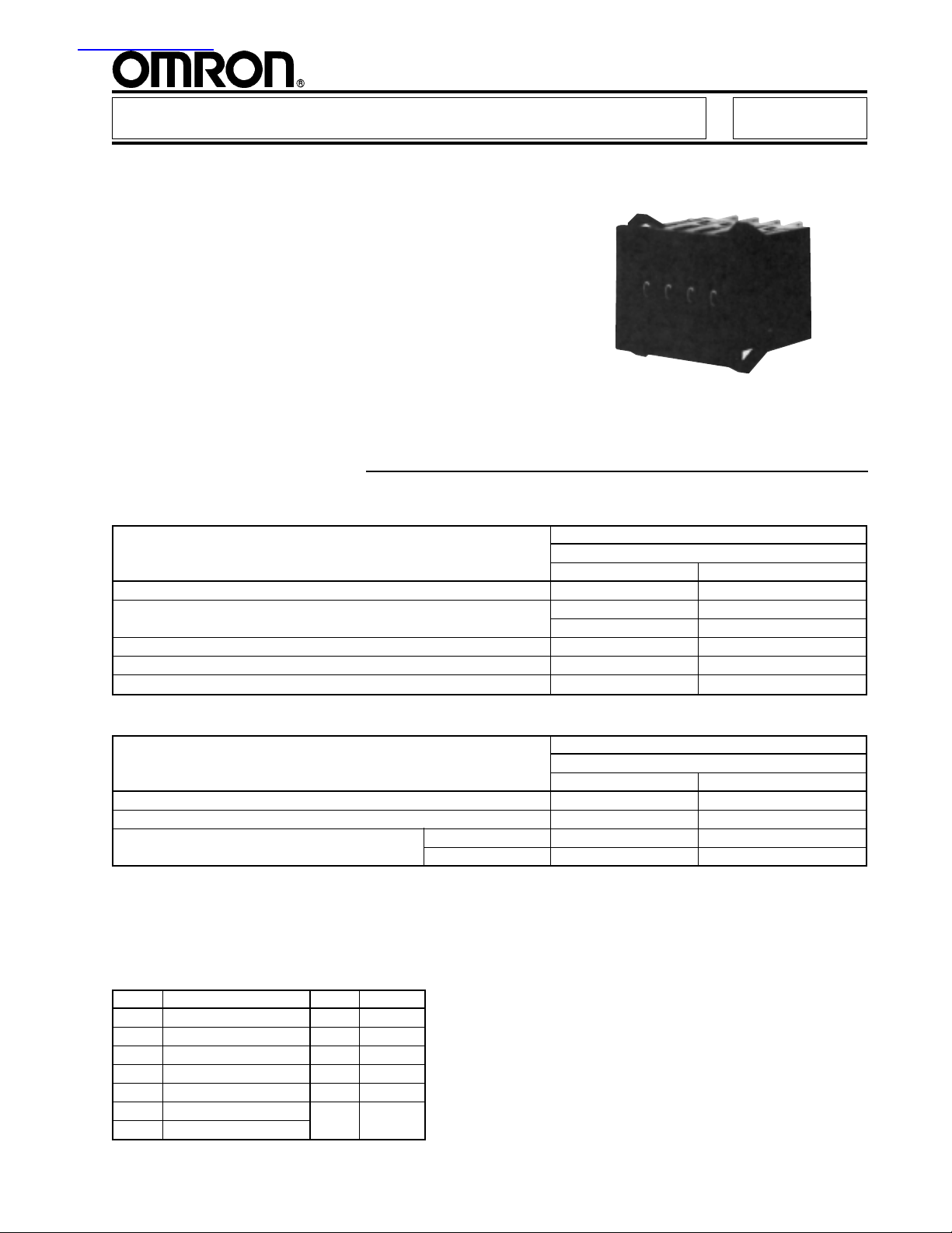
Thumbwheel Switch A7AS
Easy-to-Assemble Thumbwheel Switch
■ Dustproof construction ensures highly reliable
performance at low voltage and very small
current even under adverse environmental
conditions
■ Switch units can be assembled simply by
fitting the integral hook coupler of each unit
into the mating unit, thus eliminating the need
of bolts and nuts for assembly
Ordering Information
■ SWITCH UNITS
Part Number
Front mounting solder terminals
Output Code Light gray case Black case
03 (decimal code) A7AS-203 A7AS-203-1
06 (binary code) A7AS-206 A7AS-206-1
(binary code w/+, – display) A7AS-206-PM A7AS-206-PM-1
07 (binary code w/diode provision) A7AS-207 A7AS-207-1
19 (decimal code w/diode provision) A7AS-219 A7AS-219-1
22 (compliment of BCD) A7AS-222 A7AS-222-1
■ ACCESSORIES
Part Number
For front mounting type switch assembly terminals
Accessory Light gray Black
End Cap A7AS-M A7AS-M-1
Spacer NRT-P■■ NRT-P■■-1
Connector Solder terminal NRT-C NRT-C
PC terminal NRT-CP NRT-CP
Note: 1. When placing your order, please specify the model numbers and quantities of required switch units, end caps, and spacers,
respectively. (Note that switch units and accessories are not factory-assembled for shipment.)
2. Switch case, end cap, and spacer are made of polyacetal resin.
3. One of the following alphabetic codes must be filled into the boxed part of the model number to specify a legend to be hot
stamped on the required spacer.
4. End caps come as a set -- left and right.
Code Legend Code Legend
A Hot stamp not required H cm
B SEC J m
C MIN K ºC
D H L PCS
E g Q x 10 SEC
Fkg
Gmm
T0
A7AS A7AS
Characteristics
Switching capacity 1 mA to 0.1 A 50 VAC/28 VDC (resistive load)
Carry current 1 A (max.)
Contact resistance 200 mΩ max.
Insulation resistance 10 MΩ min. (at 500 VDC) between nonconnected terminals
1,000 MΩ min. (at 500 VDC) between each terminal and noncurrent-carrying part
Dielectric strength
Operating force 400 g max.
Vibration 10 to 55 Hz, 1.5 mm double amplitude
Shock 500 m/s2 (approx. 50 G)
Ambient temperature Operating -40o to 85oC
Storage -40o to 85oC
Humidity 85% RH max.
Service life Mechanical 1,000,000 operations (steps) min.
Electrical 50,000 operations (steps) min.
Weight (per unit) Approx. 7.6 g
Note: Data shown are of initial value.
600 VAC, 50/60 Hz for 1 minute between nonconnected terminals
1,000 VAC, 50/60 Hz for 1 minute between each terminal and noncurrent-carrying part
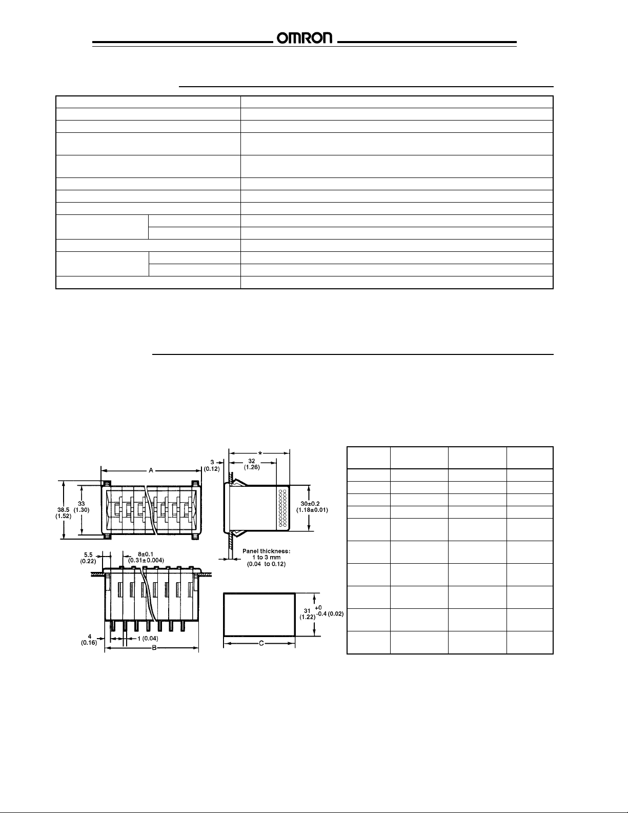
Dimensions
Unit: mm (inch)
■ SWITCH UNITS
A7AS-203(-1), A7AS-206(-1)
A7AS-207(-1), A7AS-219(-1)
A7AS-222(-1)
Panel cutout
No. of A B C
units (n) (8n + 11) (8n + 8) (B + 1)
1 19 (0.75) 16 (0.63) 17 (0.67)
2 27 (1.06) 24 (0.94) 25 (0.98)
3 35 (1.38) 32 (1.26) 33 (1.30)
4 43 (1.69) 40 (1.57) 41 (1.66)
5 51 ± 0.8 48 ± 0.8 49 (1.93)
(2 ± 0.03) (1.89 ± 0.03)
6 59 ± 0.8 56 ± 0.8 57 (2.24)
7 67 ± 0.8 64 ± 0.8 65 (2.56)
8 75 ± 0.8 72 ± 0.8 73 (2.87)
9 83 ± 0.8 80 ± 0.8 81 (3.19)
10 91 ± 0.8 88 ± 0.8 89 (3.50)
Note: Dimension * is 41.5 (1.63) for the switch with
(2.32 ± 0.03) (2.20 ± 0.03)
(2.64 ± 0.03) (2.52 ± 0.03)
(2.95 ± 0.03) (2.83 ± 0.03)
(3.27 ± 0.03) (3.15)
(3.58 ± 0.03) (3.46 ± 0.03)
output code “03” or “06,” and 53.5 (2.11) for
the switch with output code “07” or “19.”
Note: 1. Unless otherwise specified, a tolerance of ± 0.4 mm applies to all dimensions.
2. Each model number applies to a single switch unit and not to the switch assembly as shown in the drawings.
2

A7AS A7AS
■ END CAPS
A7AS-M, A7AS-M-1
[right] [left]
■ SPACERS
NRT-P■■, NRT-P■■-1
■ CONNECTORS
NRT-C NRT-CP
Note: 1. Unless otherwise specified, a tolerance of ± 0.4 mm applies to all dimensions.
2. End caps are attached to each end of the switch assembly and used to secure the switch assembly to a mounting panel.
3

A7AS A7AS
Unit: mm (inch)
■ TERMINALS
A7AS-203-■■ A7AS-206-■■ A7AS-207-■■
A7AS-219-■■
Hints on Correct Use
Refer to HINTS ON CORRECT USE under the General Information section.
OMRON ELECTRONICS, INC. OMRON CANADA, INC.
One East Commerce Drive 885 Milner Avenue
Schaumburg, IL 60173 Scarborough, Ontario M1B 5V8
1-800-55-OM RON 416-286-6465
Cat. No. GC SW5 4/98 Specifications subject to change without notice. Printed in the U.S.A.
4
 Loading...