

Omron A4E DATASHEET
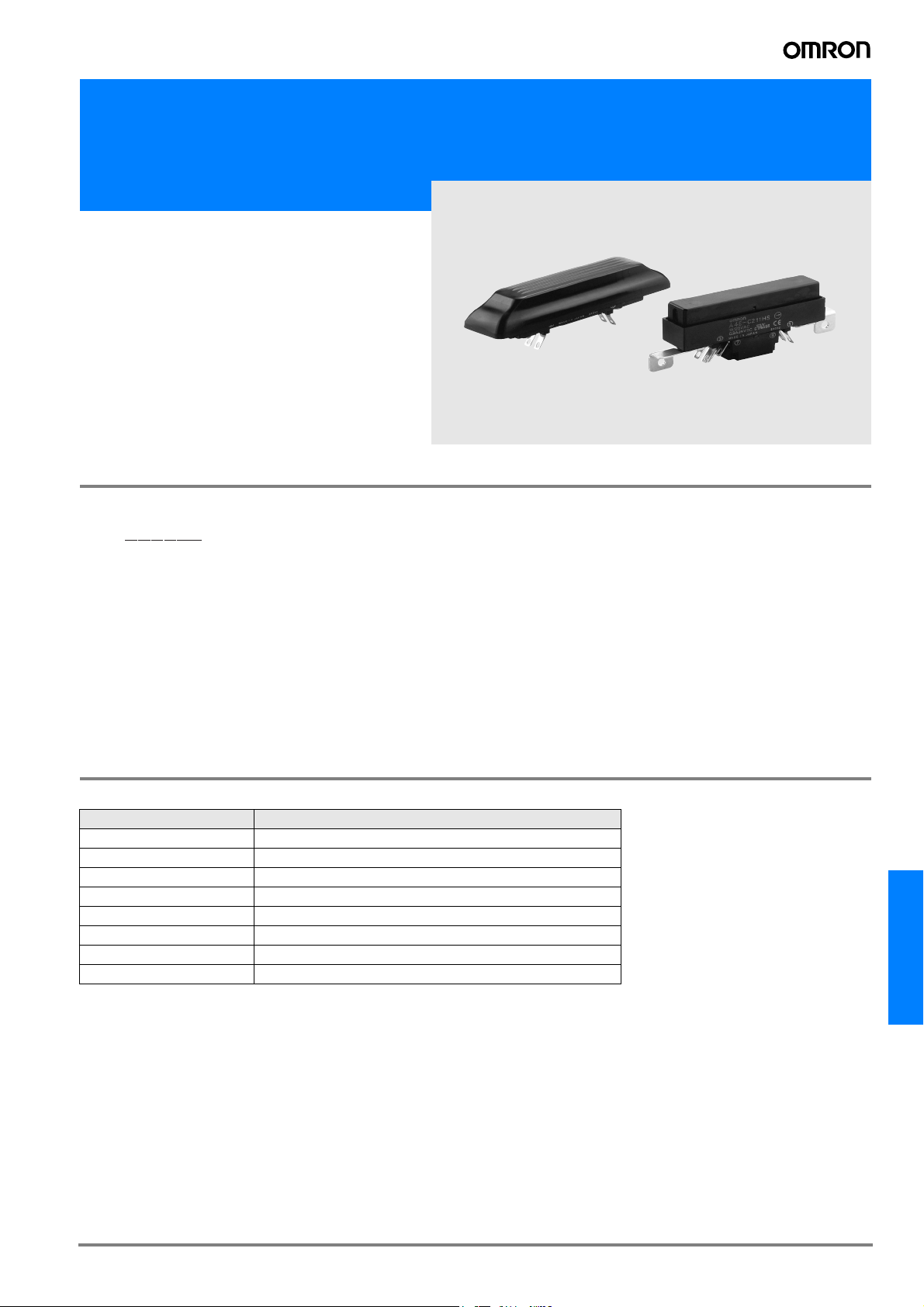
Enabling Switch
A4E
3-position Enabling Switch
for Safer Robot Operation
• Clicking feel.
• Conforms to U.S. standards
(ANSI/RIA R15.06-1999) for 3-position switches.
• Can be mounted in two directions.
Model Number Structure
Model Number Legend
A4E-######
1 2 3 4 5 6
1. Total output number
B: Two outputs
C: Four outputs
2. Enable outputs
2: Two contact outputs
3. Release monitor outputs
0: None
1: One contact output
4. Grip monitor outputs
0: None
1: One contact output
5. Mounting bracket
S: No mounting bracket
H: Horizontal mounting bracket
V: Vertical mounting bracket
6. Cover
S: No cover
A: Rubber cover
Ordering Information
List of Models
Model Specification
A4E-B200SS Two outputs, no mounting bracket, no rubber seal
A4E-B200HS Two outputs, horizontal mounting, no rubber seal
A4E-B200VS Two outputs, vertical mounting, no rubber seal
A4E-B200VA Two outputs, vertical mounting, with rubber seal
A4E-C211SS Four outputs, no mounting bracket, no rubber seal
A4E-C211HS Four outputs, horizontal mounting, no rubber seal
A4E-C211VS Four outputs, vertical mounting, no rubber seal
A4E-C211VA Four outputs, vertical mounting, with rubber seal
Approved Standards
EN 60947-5-1
UL 508
CSA C22.2 No. 14
A4E
G-299A4E
Specifications
Ratings
Rated insulation voltage 250 V
Rated ON current 2.5 A
Rated load
24 VDC, 300 mA (inductive load)
125 VAC, 1 A (resistive load)
Minimum applicable load 24 VDC, 4 mA
Impulse withstand
voltage
4.0 kV between terminals of different
polarity, 2.5 kV between terminals of
same polarity
Ambient temperature -10°C to 55°C (with no icing)
Ambient humidity 35% to 85% (with no condensation)
Storage temperature -25°C to 65°C
Characteristics
Insulation resistance 100 M min. (at 500 VDC)
Contact resistance 100 m max. (initial value)
Vibration resistance 10 to 55 Hz,
0.75-mm single amplitude min.
Shock resistance
Mechanical durability OFF-ON: 1,000,000 operations min.
Electrical durability 100,000 operations min.
Degree of protection IP65 (rubber seal type only)
2
150 m/s
OFF-ON-OFF (direct opening): 100,000
operations min.
Structure
4-contact type:2NO (enable output)
1NC (release output)
1NC (grip output)
Contact form
Direct opening for all contacts
(See note)
2-contact type:2NO (enable output)
Direct opening for all contacts (See note)
During operation: OFF-ON-OFF
Operating pattern
During reset: OFF-OFF momentary 3-position operation
Terminal shape Solder terminals
Note: Direct opening only during grip.
Contact form
2 4 6 8
1 3 5 7
SW1 SW2 SW3 SW4
Note: SW3 and SW4 are for 4-contact types only.
SW1, SW2: Enable output
SW3: Release output
SW4: Grip output
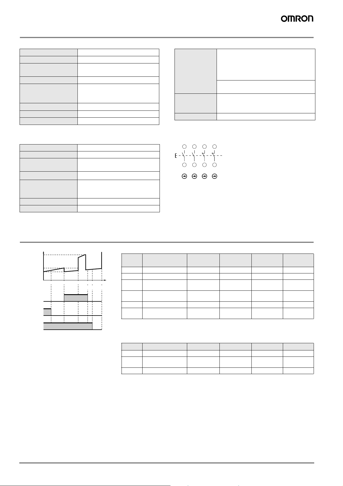
Operating Characteristics
OF2
Operating force
OF1
HF
PT1
Enable output
(A-B, C-D)
Release output
(E-F)
Grip output
(G-H)
PT2 TT1 PT3 PT4 TT2
Operating stroke
Operating stroke
Symbol Name A4E-B200#S
PT1 Release output (ON) --- --- 1 mm max. 1.2 mm max.
PT2 Enable output (ON) 3.2 mm max. 3.4 mm max. 3.2 mm max. 3.4 mm max.
TT1
PT3
PT4 Grip output (ON) --- --- 5.4 mm min. 5.4 mm min.
TT2 Max. stroke
Note:Not including the rise of the rubber cover (0.5 mm max.).
Max. enable holding
position
Enable direct
opening position
Approx.
4 mm
5.4 mm max. 5.6 mm max. 5.4 mm max. 5.6 mm max.
Approx.
6.5 mm
A4E-B200VA
(See note.)
Approx.
4.2 mm
Approx.
6.7 mm
A4E-C211#S
Approx.
4 mm
Approx.
6.5 mm
A4E-C211VA
(See note.)
Approx.
4.2 mm
Approx.
6.7 mm
Operating force (reference values)
Symbol Name A4E-B200#S A4E-B200VA
OF1 Enable operating force 7 N max. 14 N max. 7 N max. 14 N max.
HF
(See note)
OF2 Grip operating force 35 N max. 40 N max. 35 N max. 40 N max.
Note: HF indicates “holding force”.
Enable holding force Approx. 5.5 N Approx. 8 N Approx. 5.5 N Approx. 8 N
A4E-C211#S A4E-C211VA
G-300 Safety Sensors / Components
 Loading...