

Page 1
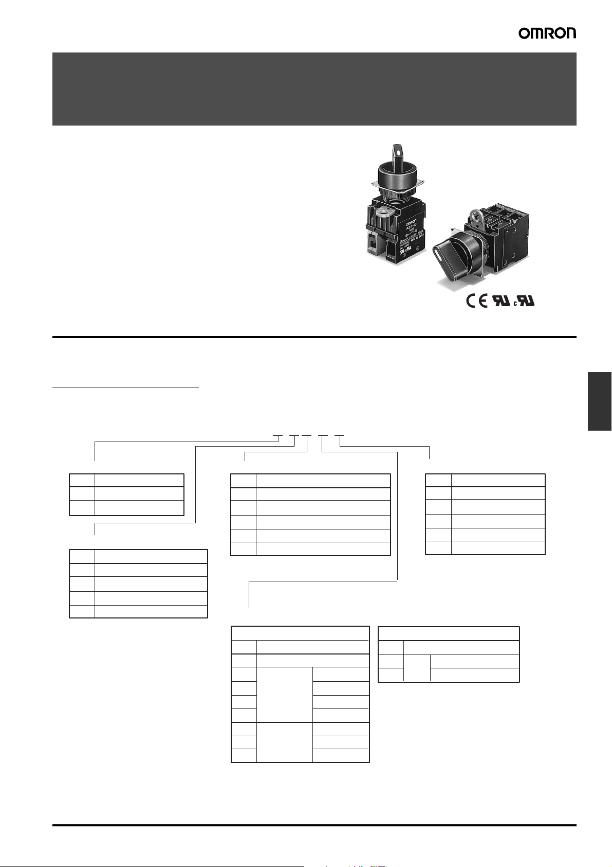
Knob-type Selector Switch
A22S/W
Install in 22-dia. or 25-dia. Panel Cutout
• Easy mounting and removal of Switch Unit.
• Increase wiring efficiency with three-row mounting of Switch
Blocks.
• Finger protection mechanism on Switch Unit provided as a standard feature.
• Use 25-dia. ring to install in 25-dia. panel cutouts.
• Mounted using either open-type (fork-type) or closed-type
(round-type) crimp terminals.
• IP65 oil resistance (non-lighted models)
IP65 (lighted models)
• EN60947-5-1
• UL and cUL approved (File No. E41515).
Model Number Structure
■ Model Number Legend
Completely Assembled
Shipped as a set which includes the Selector, Lamp (lighted models only), and Switch.
1 2 3 4 5
A22@-@@-@-@
1 Lighted/Non-lighted
Code Description
Non-lighted
S
Lighted
W
2 Number of Notches/Reset Method
Code Description
2M
2 notches/Manual
2A
2 notches/Automatic
3M
3 notches/Manual
3A
3 notches/Automatic
3 Illumination Color
Code Description
None Black (for non-lighted models only)
R
Red
G
Green
Y
Yellow
A
Blue
4 Light Source
Without Voltage Reduction Unit
Code Operating Voltage
None Non-lighted
6D 6 VDC
LED
6A 6 VAC
12A 12 VAC/VDC
24A 24 VAC/VDC
Incandescent
5 5 VAC/VDC
lamp
12 12 VAC/VDC
24 24 VAC/VDC
5 Contacts
Code Description
SPST-NO (See note 1.)
10
SPST-NC (See note 1.)
01
SPST-NO + SPST-NC
11
DPST-NO
20
DPST-NC
02
Note: 1. For models with 2 notches
2. The contacts are rated for stand-
ard loads. For microloads, refer to
Accessories section for the A22.
With Voltage Reduction Unit
None Non-lighted
LED 110 VAC (See note 2.)
T1
T2
Note: 1. The LED lamp (24 VAC/VDC) can be
lit by directly applying 110 VAC/VDC
(220 VAC/VDC) to the lamp terminal.
LED incorporates the 24-VAC/VDC
models.
2. Operational voltage: 95 to 115 VAC
3. Operational voltage: 190 to 230 VAC
220 VAC (See note 3.)
Switches
Pushbutton
Knob-type Selector Switch A22S/W G-115
Page 2
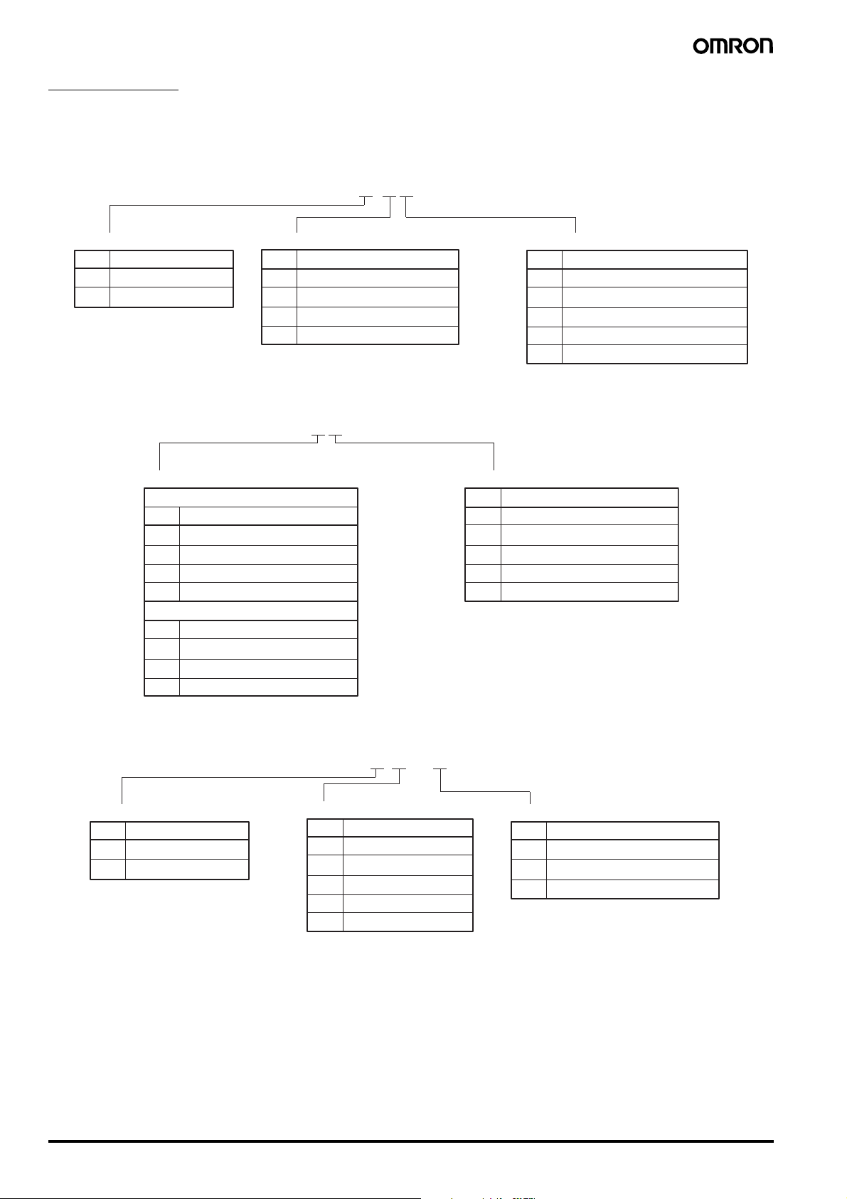
Subassembled
The Selector, Lamp, or Switch can be ordered separately. Use them in combination for models that are not available as assembled Units. These
can also be used as inventory for maintenance parts.
1. Selector
1 2 3
A22@-@@
1 Lighted/Non-lighted
Code Description
S
Non-lighted
W
Lighted
2. Lamp
2 Number of Notches/Reset Method
Code Description
2M
2A
3M
3A
A22-@@
1 Operating Voltage (Rated Voltage)
Incandescent lamp
Code Description
5 5 VAC (6 VAC)
12 12 VAC (14 VAC)
24 24 VAC (28 VAC)
H1 100 VAC (130 VAC)
LED lamp
6D 6 VDC (6 VDC)
6A 6 VAC (6 VAC)
12A 12 VAC/VDC (12 VAC/VDC)
24A 24 VAC/VDC (24 VAC/VDC)
2 notches/Manual
2 notches/Automatic
3 notches/Manual
3 notches/Automatic
1 2
3 Illumination Color
Code Description
None Black (for non-lighted models only)
R
G
Y
A
2 Illumination Color
Code Description
None Incandescent lamp
R
Red
G
Green
Y
Yellow
A
Blue
Red
Green
Yellow
Blue
3. Switch (General-purpose Load)
1 Lighted/Non-lighted
Code Description
None Non-lighted
L
Lighted
1 2 3
A22@-@M-@
2 Contacts
Code Description
10
SPST-NO (2-notch only)
01
SPST-NC (2-notch only)
11
SPST-NO + SPST-NC
20
DPST-NO
02
DPST-NC
3 Voltage Reduction Unit (Lighted Models Only)
Code Description
None Without Voltage Reduction Unit
T1
110 VAC (See note 1)
T2
220 VAC (See note 2)
Note: 1. Operational voltage: 95 to 115 VAC
2. Operational voltage: 190 to 230 VAC
G-116 Knob-type Selector Switch A22S/W
Page 3
Ordering Information
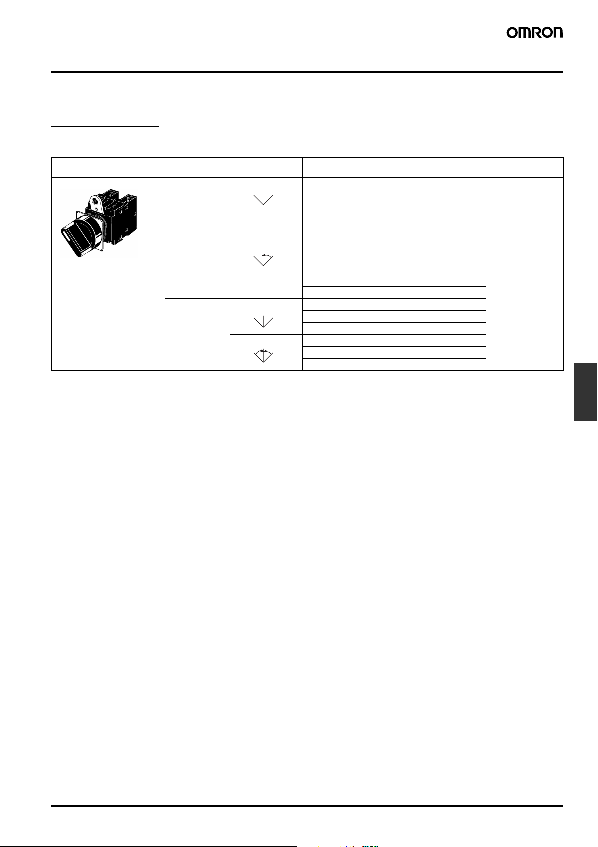
■ List of Models
Ordering as a Set
Non-lighted
Appearance Number of
Knob-type Selector Switch
A22S
notches
2 notches SPST-NO A22S-2M-10 Black
3 notches SPST-NO + SPST-NC A22S-3M-11
Resetting method Output Model Color of Selector
Manual
SPST-NC A22S-2M-01
SPST-NO + SPST-NC A22S-2M-11
DPST-NO A22S-2M-20
DPST-NC A22S-2M-02
Automatic
Manual
Automatic
SPST-NO A22S-2A-10
SPST-NC A22S-2A-01
SPST-NO + SPST-NC A22S-2A-11
DPST-NO A22S-2A-20
DPST-NC A22S-2A-02
DPST-NO A22S-3M-20
DPST-NC A22S-3M-02
SPST-NO + SPST-NC A22S-3A-11
DPST-NO A22S-3A-20
DPST-NC A22S-3A-02
Switches
Pushbutton
Knob-type Selector Switch A22S/W G-117
Page 4
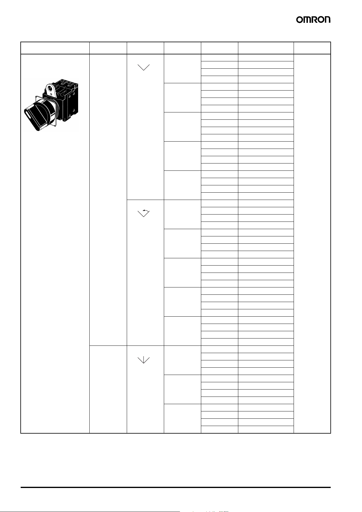
Lighted (Without Voltage Reduction Unit)
Appearance Number of
Knob-type Selector Switch
LED lighting
(without Voltage Reduction
Unit)
A22W
notches
2 notches SPST-NO 6 VDC A22W-2M@-6D-10 Insert one of the
Resetting
method
Manual
Automatic
3 notches SPST-NO +
Manual
Output Operating
SPST-NC 6 VDC A22W-2M@-6D-01
SPST-NO +
SPST-NC
DPST-NO 6 VDC A22W-2M@-6D-20
DPST-NC 6 VDC A22W-2M@-6D-02
SPST-NO 6 VDC A22W-2A@-6D-10
SPST-NC 6 VDC A22W-2A@-6D-01
SPST-NO +
SPST-NC
DPST-NO 6 VDC A22W-2A@-6D-20
DPST-NC 6 VDC A22W-2A@-6D-02
SPST-NC
DPST-NO 6 VDC A22W-3M@-6D-20
DPST-NC 6 VDC A22W-3M@-6D-02
voltage
6 VAC A22W-2M@-6A-10
12 VAC/VDC A22W-2M@-12A-10
24 VAC/VDC A22W-2M@-24A-10
6 VAC A22W-2M@-6A-01
12 VAC/VDC A22W-2M@-12A-01
24 VAC/VDC A22W-2M@-24A-01
6 VDC A22W-2M@-6D-11
6 VAC A22W-2M@-6A-11
12 VAC/VDC A22W-2M@-12A-11
24 VAC/VDC A22W-2M@-24A-11
6 VAC A22W-2M@-6A-20
12 VAC/VDC A22W-2M@-12A-20
24 VAC/VDC A22W-2M@-24A-20
6 VAC A22W-2M@-6A-02
12 VAC/VDC A22W-2M@-12A-02
24 VAC/VDC A22W-2M@-24A-02
6 VAC A22W-2A@-6A-10
12 VAC/VDC A22W-2A@-12A-10
24 VAC/VDC A22W-2A@-24A-10
6 VAC A22W-2A@-6A-01
12 VAC/VDC A22W-2A@-12A-01
24 VAC/VDC A22W-2A@-24A-01
6 VDC A22W-2A@-6D-11
6 VAC A22W-2A@-6A-11
12 VAC/VDC A22W-2A@-12A-11
24 VAC/VDC A22W-2A@-24A-11
6 VAC A22W-2A@-6A-20
12 VAC/VDC A22W-2A@-12A-20
24 VAC/VDC A22W-2A@-24A-20
6 VAC A22W-2A@-6A-02
12 VAC/VDC A22W-2A@-12A-02
24 VAC/VDC A22W-2A@-24A-02
6 VDC A22W-3M@-6D-11
6 VAC A22W-3M@-6A-11
12 VAC/VDC A22W-3M@-12A-11
24 VAC/VDC A22W-3M@-24A-11
6 VAC A22W-3M@-6A-20
12 VAC/VDC A22W-3M@-12A-20
24 VAC/VDC A22W-3M@-24A-20
6 VAC A22W-3M@-6A-02
12 VAC/VDC A22W-3M@-12A-02
24 VAC/VDC A22W-3M@-24A-02
Model Illumination
color
following letters
into the box @.
R (red)
Y (yellow)
G (green)
A (blue)
G-118 Knob-type Selector Switch A22S/W
Page 5

Appearance Number of
Knob-type Selector Switch
notches
3 notches SPST-NO +
Resetting
method
Automatic
LED lighting
(without Voltage Reduction
Unit)
A22W
Lighted (With Voltage Reduction Unit)
Output Operating
SPST-NC
DPST-NO 6 VDC A22W-3A@-6D-20
DPST-NC 6 VDC A22W-3A@-6D-02
voltage
6 VDC A22W-3A@-6D-11 Inser t one of the
6 VAC A22W-3A@-6A-11
12 VAC/VDC A22W-3A@-12A-11
24 VAC/VDC A22W-3A@-24A-11
6 VAC A22W-3A@-6A-20
12 VAC/VDC A22W-3A@-12A-20
24 VAC/VDC A22W-3A@-24A-20
6 VAC A22W-3A@-6A-02
12 VAC/VDC A22W-3A@-12A-02
24 VAC/VDC A22W-3A@-24A-02
Model Illumination
color
following letters
into the box @.
R (red)
Y (yellow)
G (green)
A (blue)
Appearance Number of
Knob-type Selector Switch
notches
2 notches SPST-NO 110 VAC A22W-2M@-T1-10 Inser t one of the
LED voltage-reduction
lighting
(with Voltage Reduction
Unit)
A22W
3 notches SPST-NO +
Note: When ordering, specify the symbol that indicates color of the Selector in the @ of the model number.
Resetting
method
Manual
Automatic
Manual
Automatic
Output Operating
SPST-NC 110 VAC A22W-2M@-T1-01
SPST-NO +
SPST-NC
DPST-NO 110 VAC A22W-2M@-T1-20
DPST-NC 110 VAC A22W-2M@-T1-02
SPST-NO 110 VAC A22W-2A@-T1-10
SPST-NC 110 VAC A22W-2A@-T1-01
SPST-NO +
SPST-NC
DPST-NO 110 VAC A22W-2A@-T1-20
DPST-NC 110 VAC A22W-2A@-T1-02
SPST-NC
DPST-NO 110 VAC A22W-3M@-T1-20
DPST-NC 110 VAC A22W-3M@-T1-02
SPST-NO +
SPST-NC
DPST-NO 110 VAC A22W-3A@-T1-20
DPST-NC 110 VAC A22W-3A@-T1-02
voltage
220 VAC A22W-2M@-T2-10
220 VAC A22W-2M@-T2-01
110 VAC A22W-2M@-T1-11
220 VAC A22W-2M@-T2-11
220 VAC A22W-2M@-T2-20
220 VAC A22W-2M@-T2-02
220 VAC A22W-2A@-T2-10
220 VAC A22W-2A@-T2-01
110 VAC A22W-2A@-T1-11
220 VAC A22W-2A@-T2-11
220 VAC A22W-2A@-T2-20
220 VAC A22W-2A@-T2-02
110 VAC A22W-3M@-T1-11
220 VAC A22W-3M@-T2-11
220 VAC A22W-3M@-T2-20
220 VAC A22W-3M@-T2-02
110 VAC A22W-3A@-T1-11
220 VAC A22W-3A@-T2-11
220 VAC A22W-3A@-T2-20
220 VAC A22W-3A@-T2-02
Model Selector
symbol (color)
following letters
into the box @.
R (red)
Y (yellow)
G (green)
A (blue)
Switches
Pushbutton
Knob-type Selector Switch A22S/W G-119
Page 6

Ordering Individually
Non-lighted Models
Selector Selector Selector
Lighted Models (without
Voltage Reduction Unit)
Lamp Lamp
Incandescent
lamp
LED LED
Lighted Models (with
Voltage Reduction Unit)
Switch
Switch (without Voltage
Reduction Unit)
Switch (with Voltage
Reduction Unit)
G-120 Knob-type Selector Switch A22S/W
Page 7

Selectors
Non-lighted (Color: Only Black is Available)
Notches Reset method
Standard lever
IP65 (oil-resistant)
Lighted
Notches Reset method Selector color
Standard lever
IP65
2 notches A22S-2M
3 notches A22S-3M
Manual
Automatic
Manual
Automatic
Left
A22S-2A
A22S-3A
A22S-3AM
automatic
Right
A22S-3MA
automatic
Notches Reset method
Standard lever
IP65 (oil-resistant)
2 notches A22S-C2M
3 notches A22S-C3M
Manual
Automatic
Manual
Automatic
A22S-C2A
A22S-C3A
2 notches Red A22W-2MR
3 notches Red A22W-3MR
Note: Either incandescent lamps or LED lamps can be used with the
above models.
Manual
Automatic
Manual
Automatic
Left
automatic
Right
automatic
Green A22W-2MG
Yellow A22W-2MY
Blue A22W-2MA
Red A22W-2AR
Green A22W-2AG
Yellow A22W-2AY
Blue A22W-2AA
Green A22W-3MG
Yellow A22W-3MY
Blue A22W-3MA
Red A22W-3AR
Green A22W-3AG
Yellow A22W-3AY
Blue A22W-3AA
Red A22W-3AMR
Green A22W-3AMG
Yellow A22W-3AMY
Blue A22W-3AMA
Red A22W-3MAR
Green A22W-3MAG
Yellow A22W-3MAY
Blue A22W-3MAA
Switches
Pushbutton
Left
automatic
Right
automatic
A22S-C3AM
A22S-C3MA
Knob-type Selector Switch A22S/W G-121
Page 8

Lamps
LED Lamp
Operating voltage 6 V 12 V 24 V 24 V
Appearance AC/DC LED light Model
DC Red A22-6DR --- --- ---
Green A22-6DG --- --- --Yellow (See note 2.) A22-6DY --- --- --Blue A22-6DA --- --- ---
AC Red A22-6AR --- --- ---
Green A22-6AG --- --- --Yellow (See note 2.) A22-6AY --- --- --Blue A22-6AA --- --- ---
AC and DC Red --- A22-12AR A22-24AR A22-24ASR
Green --- A22-12AG A22-24AG A22-24ASG
Yellow (See note 2.) --- A22-12AY A22-24AY A22-24ASY
Blue --- A22-12AA A22-24AA A22-24ASA
Note: 1. For voltage-reduction lighting, use the A22-24A@.
2. Used when the Selector color is yellow or white.
Incandescent Lamp
Operating voltage 5 VAC/VDC 12 VAC/VDC 24 VAC/VDC 100 VAC/VDC
A22-5 A22-12 A22-24 A22-H1
Super-bright
Switches (General-purpose Load)
Non-lighted
Switch operation
Automatic SPST-NO A22-10M
Lighted
Switch operation Contacts Voltage-reduction circuit
Automatic SPST-NO A22L-10M A22L-10M-T1 A22L-10M-T2
Note: For voltage-reduction lighting, use the A22-24A@.
Contacts Model
SPST-NC A22-01M
SPST-NO + SPST-NC A22-11M
DPST-NO A22-20M
DPST-NC A22-02M
Without Voltage
Reduction Unit
SPST-NC A22L-01M A22L-01M-T1 A22L-01M-T2
SPST-NO + SPST-NC A22L-11M A22L-11M-T1 A22L-11M-T2
DPST-NO A22L-20M A22L-20M-T1 A22L-20M-T2
DPST-NC A22L-02M A22L-02M-T1 A22L-02M-T2
With Voltage Reduction Unit
110 VAC
220 VAC
G-122 Knob-type Selector Switch A22S/W
Page 9

■ Accessories (Order Separately)
The A22S/W uses the same accessories as the A22. Refer to the relevant information in the section for the A22.
Specifications
With the exception of the following items, the specifications are the same as for the A22. Refer to the relevant information in the Specifications
section for the A22.
■ Operation Angle
Two notches Three notches
Note: 1. The angle used for automatic reset
is shown in parentheses.
2. FP: Free Position
■ Contacts
2-notch Type
Knob position SPST-NO SPST-NC SPST-NO + SPST-NC DPST-NO DPST-NC
3-notch Type
Knob position SPST-NO + SPST-NC DPST-NO DPST-NC
Switches
Pushbutton
Knob-type Selector Switch A22S/W G-123
Page 10

Nomenclature
Lock Ring
Selector
• Number of Notches
2 notches/3 notches
• Applicable Colors
Non-lighted: Black
Lighted: Red, green yellow, blue
Lamp
• Light Source
LED lamp
Incandescent lamp
Switch
• Contacts
SPST-NO, SPST-NC, SPST-NO + SPST-NC,
DPST-NO, DPST-NC
(Minimum applicable load: 10 mA at 5 VDC)
• Lighting Method
Non-lighted
Lighted (without Voltage Reduction Unit)
Lighted (with Voltage Reduction Unit)
Dimensions
Note: All units are in millimeters unless otherwise indicated.
■ Knob-type Selector Switch (Lighted/Non-lighted)
A22S/A22W
30 dia.
A22S-C
30 dia.
G-124 Knob-type Selector Switch A22S/W
Page 11

■ Accessories (Common to A22, A22S/W, A22K, M22, and A22E)
The A22S/W uses the same accessories as the A22. Refer to the relevant information in the corresponding section for the A22.
■ Terminal Arrangement (Bottom
View)
Non-lighted
(SPST-NO + SPST-NC)
M3.5 screw
Switch Blocks
Lighted
(SPST-NO + SPST-NC)
Switch
Blocks
Lamp socket
■ Panel Cutouts (Top View)
■ Terminal Connection
Type Connection diagram
Non-lighted
Lighted without Voltage
Reduction Unit
Lighted with Voltage
Reduction Unit
Note: The above terminal connection diagrams are examples for
SPST-NO + SPST-NC.
Bottom view
Bottom view
Bottom view
+0.4
22.3
dia.
0
Note: 1. When applying coating such as paint to the panel, the dimensions should be those after the application of coating.
Lock Ring is provided as a standard item.
2. Recommended panel thickness: 1 to 5 mm.
3. Use an A22Z-R25 Ring when mounting to a panel with 25-mm holes.
+0.5
25
dia.
0
Installation
The A22S/W uses the same installation method as the A22. Refer to the relevant information in the Installation section for the A22.
Precautions
The precautions for the A22S/W are the same as those for the A22. Refer to the relevant information in the Precautions section for the A22 and
the Technical Information for Pushbutton Switches (Cat. No. A143).
Switches
Pushbutton
Knob-type Selector Switch A22S/W G-125
Page 12

ALL DIMENSIONS SHOWN ARE IN MILLIMETERS.
To convert millimeters into inches, multiply by 0.03937. To convert grams into ounces, multiply by 0.03527.
Cat. No. A129-E1-02
In the interest of product improvement, specifications are subject to change without notice.
G-126 Knob-type Selector Switch A22S/W
 Loading...