

Page 1

Microwave Type RFID System
V690 Series
User’s Manual
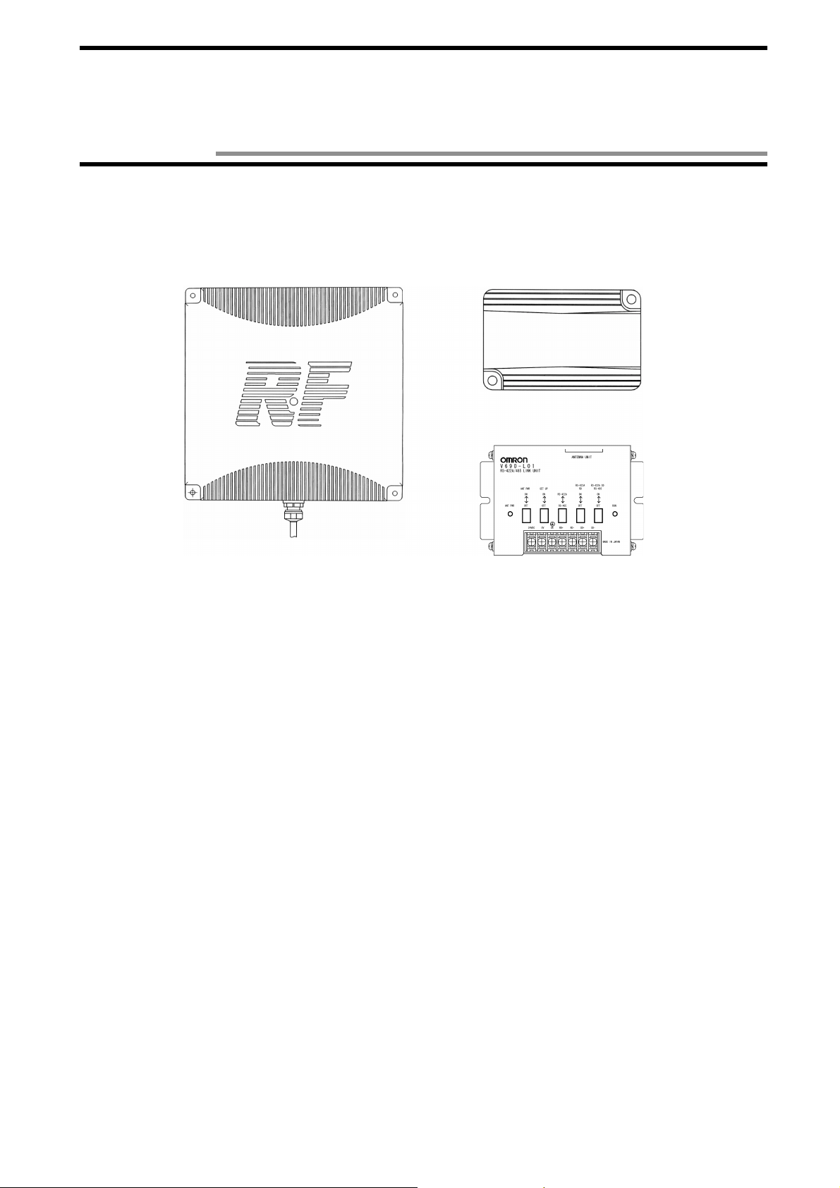
Read/Writ e Antenna, ID Tag, and Link Unit
Read/Write Antenna
Model V690-HMG01
ID Tag
Model V690-D8KR01
Link Unit
Model V690-L01
Catalog No. Z149-E1-01
Page 2

Introduction
Thank you very much for choosing the microwave type RFID system V690 Series. The V690 Series has been d eveloped by OMRON,
based on the advanced techn ol ogy and extensive experience. This user’s manual describes the functions , performance and usage of
V690 Series.
When you use the V690 Ser ies, follow the inst ructions below:
• V690 series must be operated by a qua lif ied electrical engineer who ex perts on knowledge about electri city.
• Read this user’s manual with care, underst and the V690 Series fully and use it appropriately.
• Keep this user’s manual handy.
Notes on use
When you use the V690 Series in the following environments, we would like you to operate it within the rating and functions, take
safety measures such as fail-safe system and consult our person in charge.
(1) Use in an unsuitable condition or environment which is not described in the user’s manual
(2) Use for nuclear energy control, railroad, aeronautica l system, car, combustion equipmen t, medical equipment, amusement
facility, safety device, etc.
(3) Use for application which may have a great influence on people’s lives and property and must be executed safely in particu-
lar.
Page 3
Notes on safety
•••• Warning symbols and meanings
For safety operation of V690 Series RFID system, the warning symbols below are used in this User’s Manual.
The notes mentioned below gives you an important message for safety operation. Be sure to follow the instruction.
The warning symbols and meaning are as follo ws:
WARNING
•••• Description of symbol
The hazard or unsafe practice could result in severe injury or death.
•••• Explosive!
It may burst under a particular condition.
Page 4

WARNING
Lithium battery is conta ined in an ID ta g. Do not dis asse mble, heat abo ve 212 °F (100°C) or incin-
erate the ID tag. Otherwise fire, explosion and/or burns may result..
Page 5

.
Remarks
For the safety, be sure to follow the instructions below:
1. Do not operate this device in any flammable, explosive or corrosive gas environment.
2. Do not disassemble, repair nor remodel this device.
3. Tighten the base lock screws and terminal block screws completely.
4. Be sure to use wiring crimp terminal of a specified size.
5. The 24 VDC power supply must meet the following items:
(1) Such 24 VDC power suppl y must be us ed for the V6 90 S eries o nl y and must no t be co nn ected to any ot he r dev ices n or ap para-
tuses.
(2) Voltage of such DC power supply must be wit hin the specified rating (24 VDC +10%-15%).
6. Be sure to follow any other Warnings, Cautions and Correct Usage mentioned in this manual.
.
Correct Usage
1. Do not install model V6 90-HMG01, model V690-D8KR01 and model V690-L01 in the following areas:
• Place exposed to the direct sunlight.
• Humid place where moisture condensat ion may occur.
• Place affected by vibration or impact.
2. Preliminary check of installation site.
This device uses the frequency band 2450 MHz for the communi cation between an antenna and ta g. Some of radio equipment, su ch
as wireless LAN, cellular phon e, personal handyph one system and transceiv er, motor and switching power supply ma y generate a
radio wave (noise) which affects th e commun icat ion wi th a t ag. I f you must use this d evic e near s uch he ater, we would li ke to ask
you to check the influence in advance.
To minimize general influence of noise, follow the instr uctions below:
• Ground any metallic material located around this device according to Class D (Class III).
• Wire this device keeping away f rom high voltage and h eavy current.
3. Ambient environment and communication range
• The communication range varies depending on the installation site environment. This is because a metal material and the ground
reflect a radio wave, and wa ter and human bod y a bsorb it . Loc ate an anten na and ta g in th e commu ni cation range an d ch eck t he
radio wave environment in advance.
• The Read/Write antenna model V690-HMG01 has a co mmunication test command to check the radio wave en vironment at a
working site. (Refer to Section 3-5.)
4. Be sure to ground any ground terminal according to Class D (conventional Class III). Otherwise, performance may deteriorate.
5. Cleaning of model V69 0- H MG01, model V690-D8KR0 1 and model V690-L01
• Do not use any thinner. Resin material and case paint are dissolved by thinner.
Page 6

Contents
Contents
Chapter 1 Features and System Configuration
1-1 Features ..............................................................................................................................1-1
1-2 System Configuration ........................................................................................................1-2
1-3 Operation Overview ...........................................................................................................1-4
Chapter 2 Specifications and Performance
2-1 Read/Write Antenna Model V690-HMG01 ....................................................................2-1
2-1-1 Specifications ...........................................................................................................2-1
2-1-2 Outside Dimension ...................................................................................................2-1
2-1-3 Signal of Supplied Connector ...................................................................................2-2
2-1-4 Indicator ....................................................................................................................2-2
2-2 ID Tag Model V690-D8KR01 .........................................................................................2-3
2-2-1 Specifications ...........................................................................................................2-3
2-2-2 Outside Dimension ...................................................................................................2-3
2-2-3 Memory Map ............................................................................................................2-4
2-2-4 Battery Life Characteristic .......................................................................................2-5
2-2-5 Battery Voltage Alarm Function ..............................................................................2-5
2-3 RS-422A/485 Link Unit Model V690-L01 ....................................................................2-6
2-3-1 Specifications ...........................................................................................................2-6
2-3-2 Outside Dimension ...................................................................................................2-6
2-3-3 Function ....................................................................................................................2-7
2-4 Connecting Cable ...............................................................................................................2-8
2-4-1 Specifications ...........................................................................................................2-8
2-4-2 Outside Dimension ...................................................................................................2-8
2-5 Communication Performance ..........................................................................................2-10
2-6 Communication Specifications ........................................................................................2-11
Chapter 3 Functions
3-1 Single/FIFO/Multi Mode Access Function ........................................................................3-1
3-2 Communication 2 m Mode/5 m Mode Switching .............................................................3-2
3-3 Radio Wave Channel Switching ........................................................................................3-3
3-4 Simplified Communication Test ........................................................................................3-4
3-5 Communication Test ..........................................................................................................3-5
3-6 Write Protect Function .......................................................................................................3-6
3-7 ID Tag Power-Saving Function .........................................................................................3-8
Chapter 4 Installation and Connection
4-1 Read/Write Antenna and ID Tag .......................................................................................4-1
4-1-1 Installation Environment ..........................................................................................4-1
Contents-1
Page 7

Contents
4-1-2 How to Install Antenna ............................................................................................4-4
4-1-3 Rainproofing of Antenna ..........................................................................................4-5
4-1-4 How to Install Tag ....................................................................................................4-6
4-1-5 How to Connect Connecting Cable to Antenna .......................................................4-7
4-2 How to Wire to Host Device .............................................................................................4-8
4-2-1 How to Wire RS-232C Interface ..............................................................................4-8
4-2-2 How to Wire When Connecting RS-422A/485 ......................................................4-11
4-3 Link Unit ..........................................................................................................................4-16
4-3-1 Installation Environment ........................................................................................4-16
4-3-2 How to Install .........................................................................................................4-16
4-3-3 How to Wire ...........................................................................................................4-17
4-3-4 Switch Setting ........................................................................................................4-20
Chapter 5 Control from Host Device
5-1 Operation Status of Read/Write Antenna and ID Tag .......................................................5-1
5-2 Communication Operation Sequence ................................................................................5-2
5-2-1 Communication Mode with Command ....................................................................5-2
5-2-2 Communication Mode with Communication Designation .......................................5-5
5-2-3 Other Communication Mode ....................................................................................5-8
5-3 Communication Response Format .....................................................................................5-9
5-4 Communication and Communication Designation List ..................................................5-11
5-5 Data Code Designation ....................................................................................................5-14
5-6 Communication Response Flow ......................................................................................5-16
5-7 Tag Communication Command .......................................................................................5-17
5-7-1 Read ........................................................................................................................5-17
5-7-2 ID Code Read .........................................................................................................5-19
5-7-3 Tag Designation Read ............................................................................................5-21
5-7-4 Write .......................................................................................................................5-23
5-7-5 Tag Designation Write ...........................................................................................5-25
5-7-6 Data Fill ..................................................................................................................5-27
5-7-7 Tag Designation Data Fill ......................................................................................5-29
5-7-8 Communication Test ..............................................................................................5-30
5-8 Antenna Operation Command .........................................................................................5-31
5-8-1 Auto Repeat Cancel ................................................................................................5-31
5-8-2 Reset .......................................................................................................................5-32
5-8-3 Request to Respond ................................................................................................5-33
5-8-4 Request to Retransmit ............................................................................................5-34
5-9 Antenna Setting Command ..............................................................................................5-35
5-9-1 Radio Wave Transmission ON/OFF ......................................................................5-35
5-9-2 Communication Range Mode and Radio Wave Channel Selection .......................5-36
5-9-3 Radio Wave Output Status Read ............................................................................5-37
5-9-4 Setting of Time to Wait Tag ...................................................................................5-38
5-9-5 Command Data Response Time Setting .................................................................5-39
5-9-6 Read Data Length Setting ......................................................................................5-40
5-9-7 Host Communication Condition Setting ................................................................5-41
Contents-2
Page 8

Contents
5-9-8 Station Number Setting ..........................................................................................5-42
5-9-9 Setting Read ...........................................................................................................5-43
5-10 Termination Code List .....................................................................................................5-44
Chapter 6 From Startup to Run
6-1 Trial Operation ...................................................................................................................6-1
6-2 Diagnosis Function ............................................................................................................6-2
6-3 Error List ............................................................................................................................6-3
6-4 Errors and Countermeasures ..............................................................................................6-4
6-5 Maintenance and Inspection ..............................................................................................6-5
6-6 Troubleshooting .................................................................................................................6-6
Chapter 7 Communication Performance and Characteristic Data (Reference)
7-1 Communication Area (Reference) .....................................................................................7-1
7-2 Influence of Ambient Temperature (Reference) ................................................................7-2
7-3 Influence of Tag Rotation Angle (Reference) ...................................................................7-3
7-4 Communication Time (Reference) ....................................................................................7-4
7-5 Mutual Interference Between Antennas (Reference) .........................................................7-6
7-6 Space to Wireless LAN Cellular Phone (Reference) .........................................................7-7
7-7 Influence of Tag Installation Angle (Reference) ...............................................................7-8
7-8 Influence of Back Metal (Reference) ...............................................................................7-10
Appendix
Appendix 1 Glossary ...................................................................................................Appendix-1
Appendix 2 JIS8 Unit Code List (ASCII Code List) ..................................................Appendix-4
Appendix 3 Protective Structure .................................................................................Appendix-5
Appendix 4 Order Format List ....................................................................................Appendix-6
Contents-3
Page 9
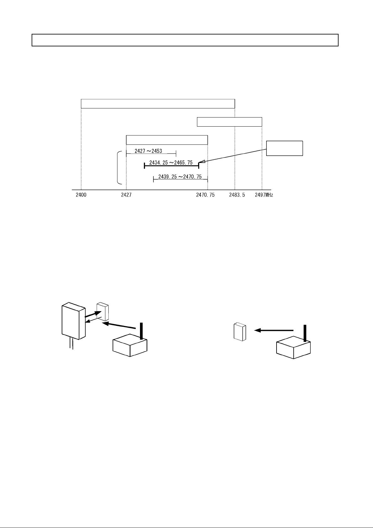
Notes on Interference to Second-Generation Low-Power Data Communication System (Wireless LAN), Cellular Phone, etc.
1. Radio inter ference between radio stations
The frequency 24 50 MHz ban d (2 43 4.25 - 24 65 .75 M Hz) u sed by the micr owave R FID syst em V 690 i s d esign ated f or sec ond-ge neration low-power data communica tion syst em (wireless L AN), local area radio stat ion (a license requ ired) for mob ile object identification and specified low-power radio station (no license required) as well as industrial, scientific o r medical equipment su ch as
microwave oven. T herefore, the radio in terference is expec ted in su ch frequ ency ban d. Moreo ver, the cellular pho ne and p ersonal
handyphone system (900 MHz - 1900 MHz) may generate the radio interference.
Second-generation low-power data communication system (wireless LAN)
Low-power data communication system
Mobile object identification (Microwave RFID)
Specified
frequency
band
Frequency band of
this product V690
2. Possible trouble du e to radio interference
• Communication failure in RFID system
The radio wave from an ID tag to an tenn a is wea k and , th er efore , th e co mmu nica tio n b etween the ante n na a nd ID ta g ma y fa il d ue
to radio interference caused by any other devices. Keep sufficient space between the RFID system and any other devices. For the
space, refer to Section 7-6.
• ID tag battery power loss
An electronic circuit in the ID tag is started by a radio wave of other device and the battery power may be consumed considerably.
V690 has a tag power-saving function (refer t o Section 3-7) to control the battery power. Nevertheless, the batter y power may be
still consumed depending on a work in g env iron m ent. So , ke e p sufficient space between the ID ta g a nd any ot he r de v ices. Fo r the
space, refer to Section 7-6.
♦ Communication failure in RFID system
ID Tag
♦ ID tag battery power loss
Antenna
Wireless LAN
ID Tag
Wireless LAN
Page 10
3. Preparation at working site
(1) Check at working site
1) Before using V690, check that second-generation low-power data communication system (wireless LAN), local area radio station
(microwave RFID system) for mobile object identification or specified low-power radio station (microwave RFID system) does
not work near V690.
2) If V690 causes radio interfer ence t o the l ocal area radi o sta tion fo r mob ile ob ject ident ificat ion, ch ange t he ch annel immediately
or stop the V690 emitting the radio wave. Then, we would like you to contact us to take necessary actions to avoid interference
(e.g., partitioning).
3) If V690 cau ses radi o i nte rfe renc e t o t he secon d-g ene rat io n l ow-p ower da ta c ommuni c atio n sys te m or s pec ifi ed l o w-po wer ra di o
station for mobile object identification or if any other trouble happens, feel free to contact us.
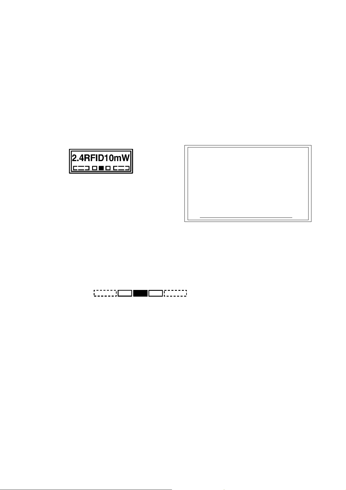
(2) Product labe l and caution label
The product label and caution label come with the product.
• Affix the product label to a visible position on an antenna unit.
• Affix the caution label to a visible po sition n ear the anten na. The cau tion labe l must show the con tact add ress or phone n umber of
a person in charge of installation or any other related information.
♦ Product label
(3) Meaning of product label
• 2.4: Radio equipment wh ich uses the frequen cy band 2.4 GHz.
• RFID: The application of Radio Frequency Identification.
• 10 mW: A value of antenna power.
• !!!: Frequency band as follows:
The V690 antenna uses the frequ ency band 2450 MHz and, therefore "2450" is marked.
Frequency band: 2440 2450 2455 MHz
2400 - 2427
Frequency band: 2470.75 - 2483.5 MHz
♦ Caution label
The frequency 2450 MHz band of this device is designated for second-generation low-power data communication system (wireless LAN), local area
radio station (a license required) for mobile object identif ication and specified
low-power radio station (no license required) as well as industrial, scientific
or medical equipment such as microwave oven.
1) Before using this device, check that second-generation low-power data
communication system (wireless LAN), local area radio station (microwave RFID system) for mobile object identification or specified low-power
radio station (microwave RFID system) does not work near this device.
2) If this device causes radio interference to the local area radio station for
mobile object identification, change the frequency band immediately or
stop this device emitting the radio wave. Then, we would like you to contact below to take necessary actions to avoid interference (e.g., partitioning).
3) If this device causes radio interference to the second-generation lowpower data communication system or specified low-power radio station
for mobile object identificati on or if any other trouble happens, fe el fr ee to
contact below.
Contact:
Page 11
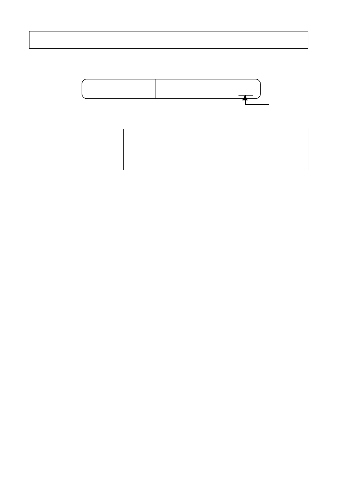
Manual Revision History
A manual revision history code is added to the end of catalog number shown at the left lower part of front cover
and back cover
Catalog No. SCLB-Z149-E1-01!
Revision
Code
-- October 2000 First Edition
Date of
Revision
Reason of Revision / Revised Page
!
!!
Revision code
Page 12
Chapter 1 Features and System Configuration
1-1 Features
The V690 Series is the microwave type RFID system which has achieved long-range and high-performance communication. This V690
system is the most suitable for an assembly line, physical distribution, and product control applications.
Read/Write Antenna
Model V690-HMG01
Read/Write Antenna Model V690-HMG01
(1)
• Consists of an antenna unit which communicates with the ID tag, and a controller unit which controls the communication.
• The antenna unit has achieved the transmi ssion speed 600 kbps and max imum communication r ange 5 m.
• The antenna uses ci rcularly polarized wave as radio wave. So, the ID tag facing the antenna can c ommunicate at any ro tating
angle on the medial axis. Th e maximum communication range varies depending on the tag angle.
• This antenna is a specified low-power radio station and, therefore, any radio station license is not required.
• The Multi Access funct i on which enables to access sev eral tags in the antenna communication area and FIFO (First-In First-Out)
function which enables to access the tags coming in the communication area sequentiall y one by one.
• By a command from a host dev ice, the comm un ic ati on 2 m Mode and 5 m Mode c an be switche d to eac h othe r and a r adio wave
channel can be swi tched at a working site. You can select the most suitab le commu nicatio n range at a worki ng site a nd prev ent
the mutual interference between antennas easily.
• The controller contains bo th of the RS-232C and RS-422A interfaces. So, it can connect to a general-purpose PC or programmable controller (PLC) which have RS-232C. Also, several antennas can be connected to one h ost device.
• A simplified communication test function, which can check the communication with a tag without a host device, and a communication test, which can check a radio wave environment at a working site, are available.
ID Tag
Model V690-D8KR01
RS-422A/485 Link Unit
Model V690-L01
(2) ID Tag Model V690-D8KR01
• This tag contains a battery and the memory capaci ty is 8 kbytes.
• Write Protect is available to disable writing by 256 bytes.
• Protective st ructure based on the IEC Standard IP67 (JEM Standar d IP67g) has been achieved. So, this tag can be used e ven in a
place splashed with water and oil.
• The battery life is 5 years at 25°C (a reference value). The battery is not replaceable, but a power-savi ng function and battery
voltage alarm function are available.
(3) RS-422A/485 Link Unit Model V690-L01
• Use when the communication with a host device is made through the RS-422A or RS-485.
• The power supply to the Read/Write antenna can be turned ON/OFF, the operation/setting mode can be switched, RS-422A/RS485 can be switc he d and terminating resistance can be turned ON/OFF.
1-1
Page 13
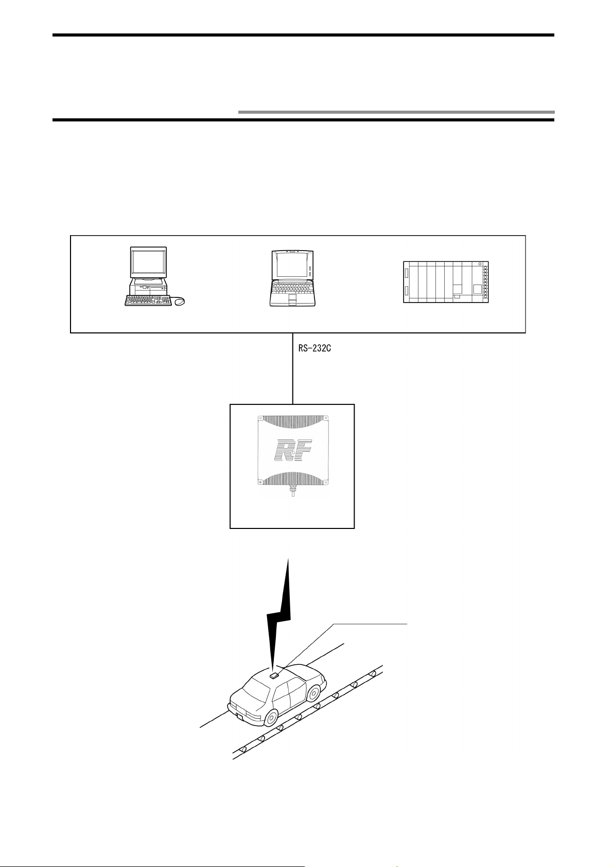
1-2 System Configuration
•••• Example of system configuration of model V690-HMG01 (1:1 connection in a host communication through RS-
232C)
Model V690-HMG01 cont ains a ser ial int erf ace based on RS-2 32C and c an co nn ect t o a ge ner al- purp ose PC o r prog ramma bl e co ntroller (PLC) easily. All the communications with the tag are controlled according to the instructions (by commands) from a host
device.
<Host Devices>
Desktop PC
Communication
Notebook PC
Cable
Model V690-A4!
Read/Write Antenna
Model V690-HMG01
Programmable Controller
(PLC)
ID Tag
Model V690-D8KR01
1-2
Page 14
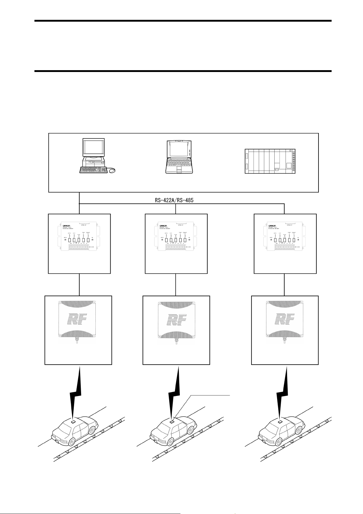
1-2 System Configuration
•••• Example of system configuration of Model V690-HMG01 (1:N connection in a host communication through RS-
422A (4-wire)/RS-485 (2-wire))
Model V690-HMG01 cont ains t he R S-4 22A /485 in ter face and c an co nn ect a max imum of 32 R S- 422A/ 485 l ink unit s mo del V6 90L01 to one general-purpose PC or programmable controll er (PLC). A maximum l e ngth of RS-422A/48 5 is 300 m.
<Host Devices>
Desktop PC
Link Unit
Model V690-L01
Cable
Model V690-A5!
Read/Write Antenna
Model V690-HMG01
Notebook PC
Link Unit
Model V690-L01
Cable
Model V690-A5!
Read/Write Antenna
Model V690-HMG01
Programmable Controller
(PLC)
Link Unit
Model V690-L01
Cable
Model V690-A5!
Read/Write Antenna
Model V690-HMG01
Communication
Communication
ID Tag
Model V690-D8KR01
Communication
1-3
Page 15
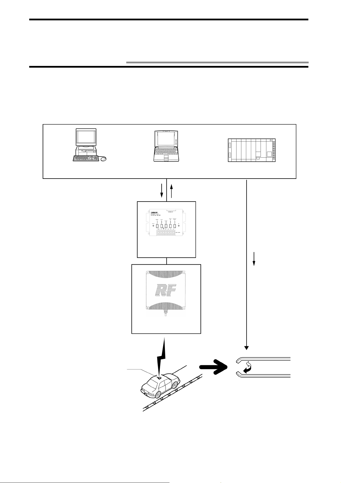
1-3 Operation Overview
Showing an example of assignment in car transportation, the V690 S eries operation overview is described bel ow.
The ID tag is mounted on a car body and the destination is assigned to the car according to the destination information stored in the ID
tag.
<Host Device>
Desktop PC
Auto command
(Read)
Read/Write Antenna
Model V690-HMG01
Notebook PC
Link Unit
Model V690-L01
Programmable Controller
(PLC)
Response
I/O Control
Communication
ID Tag
Execution
(Assignment)
(1)When an auto command is sen t from a host device to the Read/Write antenna, the antenna is ready to work and waits for an ID tag.
(2)When any ID tag has come in the antenna’s communication area, the antenna returns data of memory area specified by the auto com-
mand (Read) as a response.
(3)Based on the data, the host device controls a transportatio n devic e and assigns the de stination.
1-4
Page 16
Chapter 2 Specifications and Performance
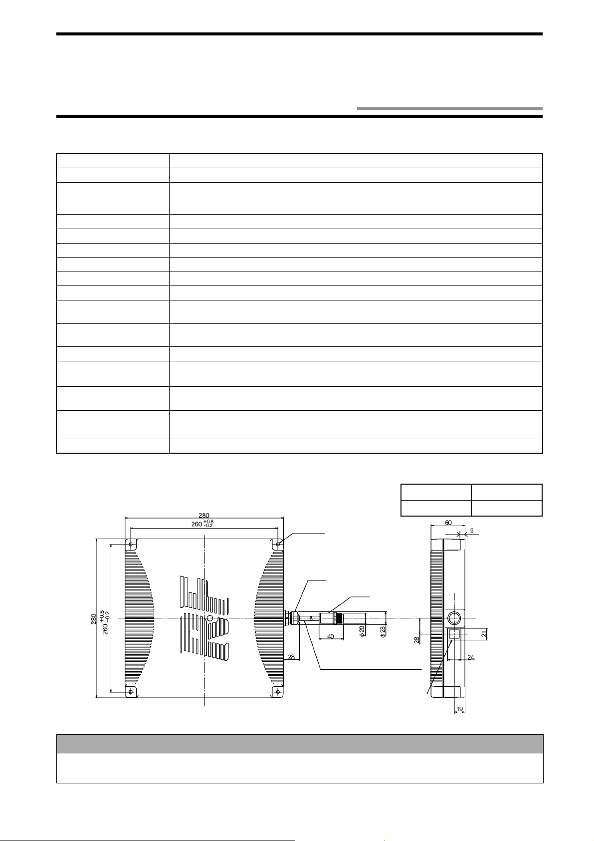
2-1 Read/Write Antenna Model V690-HMG01
2-1-1 Specifications
Item Specifications
Emitting frequency 2450 MHz band (2434.25 - 2465.75 MHz)
Power supplied to
antenna
Power supply 24 VDC +10%/-15%
Consumption current 0.5 A or less.
Ambient operating temperature
Ambient operating humidity
Ambient storage temperature
Ambient storage humidity 35 to 85%RH (without moisture conde nsation)
Insulation resistance 20 MΩ or more (at 100 VDC mega).
Withstand voltage 1,000 VAC, 50/60 Hz for 1 minute, detected current 1 mA or less.
Protective structure IP62 (IEC60529 Standard) * A cable outlet turns downward.
Vibration resistance
Impact resistance
Indicator Power supply, radio wave emission, host transmission, tag transmission.
Cable length 0.5 m. A round connector (waterproof) comes with the cable.
Weight 2.6 kg or less (including a cable of 0.5 m in length and connector)
5 mW in the communication range 2 m mode. 10 mW in the communication range 5 m
mode (specified low-power radio station - radio equipment for mobile object identification).
* A user is not required to apply a license for radio station.
-20 to +60°C (without icing)
35 to 85%RH (without moisture condensation)
-20 to +60°C (without icing)
Between a group of cable terminals and a case.
Between a group of cable terminals and a case.
10 to 150 Hz, single am plitud e 0.35 mm, max imu m acc elera tion 50 m/s2. Performing sweep 10 times
for 8 minutes in upward, downward, leftward, rightward, forward and backward directions.
Giving impact of 150 m/s
2
3 times each in upward, downward, leftward, rightward, forward
and backward directions, i.e., 18 times in total.
2-1-2 Outside Dimension
4-φ6 Mounting hole
Bush
Vinyl insulation round c ord, φ7.5, 12-core,
0.5 m in length
Correct Usage
Case material ABS resin
Cable Vinyl chloride
Connector
Indicator
(Unit: mm)
Protective structure IP6 2 of the a ntenna is the pr otecti on agai nst the d rop of w ater. If the antenna is splashed with water
spray or water jet flow, cover the antenna with a protection plate. (Refer to "Appendix 3 - Protective Structure".)
2-1
Page 17
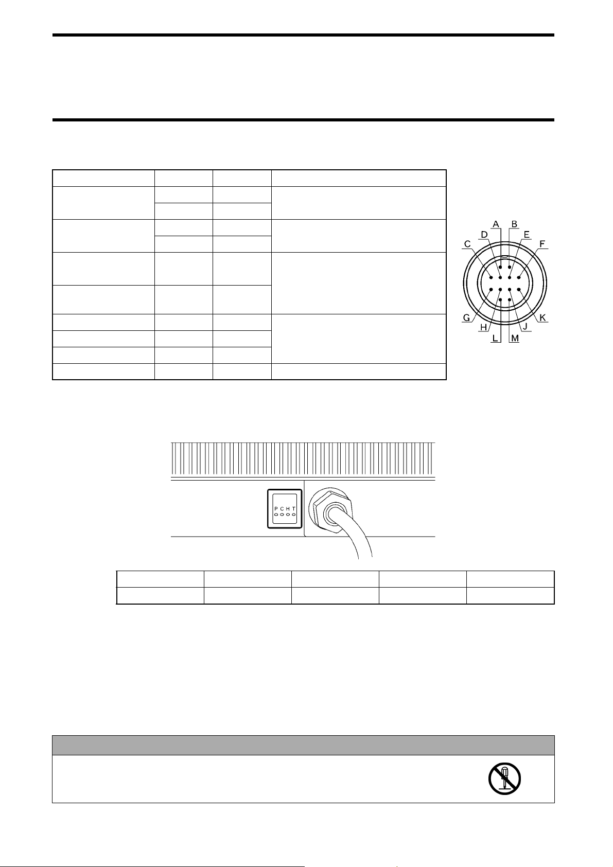
2-1 Read/Write Antenna Model V690-HMG01
2-1-3 Signal of Supplied Connector
Item Symbol
Power supply +24V A Supply 24 VDC.
0V B
Setting +P C
-P D
RS-422A RD
(Receiving)
RS-422A SD (Sending)
RS-232C Receiving Rx J Use for the communication in RS-232C.
RS-232C Sending Tx K
RS-232C Signal 0V SG L
Frame ground GR M Ground accord ing to Class D.
RD+ E Use for the communication in RS-422A.
RD- F
SD+
SD-
Pin Number
G
H
Short-circuit at the setting mode. Refer to Section 5-1.
Do not conne ct at the operation mode
(Terminating resistance 220 Ω is connected to both of RD and SD in the
antenna.) Do not connect when RS232C is used.
Do not connect when RS-422A/485 is
used.
Usage
2-1-4 Indica tor
(1) The i tems below can be checked through t he antenna indicator.
Pin Layout
Indicator P (Red) C (Red) H (Red) T (Red)
Meaning Power supply
P (Power): Turns on whe n 24 VDC power is being su pplied to the antenna.
C (Carrier): Turns on when the antenna is emitting a radio wave.
H (Host): Turns on when the antenna is sending data to a host device.
T (Tag): Turns on when the antenna is sending data to a tag.
(2) By enabling the setting mode, you can check the communication range to a tag without connecting to a host device. Refer to Section
3-4.
(3) If an operation fails, troubleshoot according to those indicators which turn on or blink. Refer to Section 6-2.
Do not disassemble it nor touch the inside when the power supply turns on. Otherwise, trouble
may be caused.
2-2
Radio wave emission
Correct Usage
Host transmission Tag transmission
Page 18
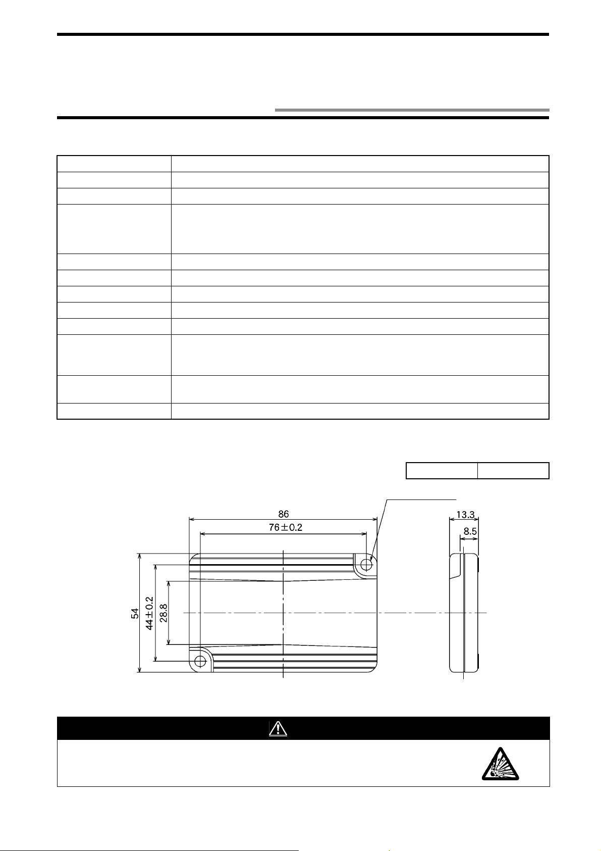
2-2 ID Tag Model V690-D8KR01
2-2-1 Specifications
Item Specifications
Memory capacity 8 Kbytes
Type of memory SRAM (volatile memory). Data is backed up by a battery.
Memory life (Referen ce
value)
Ambient operating temperature
Ambient operating humidity
Ambient storage temperature
Ambient operating humidity
Protective structure IP67 (IEC60529 Standard) / IP67g (JEM1030 Standard)
Vibration resistance
Impact resistance
Weight 60 g or less.
5 Years.
* Ambient temperature 25°C. For details, refer to Section 2-2-4.
Battery not replaceable.
Battery voltage alarm function.
-20 to +60°C in the communica tio n. -25 to +70°C not in the communication (without icing).
35 to 85%RH (without moisture condensation)
-25 to +70°C (without icing)
35 to 85%RH (without moisture condensation)
10 to 2,000 Hz, single amplitude 0.75 mm, maximum acceleration 150 m/s
sweep 10 times for 15 minutes in upward , downw ard, leftwa rd, rightw ard, forwa rd an d backward directions.
Giving impact of 500 m/s2 3 times each in upward, downward, leftward, rightward, forward
and backward directions, i.e., 18 times in total.
2
. Performing
2-2-2 Outside Dimension
Case material ABS resin
2-φ4.5 Mountin g ho l e
(Unit: mm)
WARNING
Never disassemble, p res su re, deform, heat to 100°C or more nor burn an ID tag . T he I D tag co ntains lithium battery and it may ignite, burst or burn.
2-3
Page 19
2-2 ID Tag Model V690-D8KR01
2-2-3 Memory Map
♦♦♦♦ User data
Memory capacity of user data of ID tag is 8,192 bytes. Minimum unit of memory is 1 byte and the memory is specified by the ad dress
(0000h to 1FFFh). h: Hexadecimal number
Data address
0000h to
1FFFh
Bit
76543210
User data (8 kbytes)
Initial value: all 00h
Writing by
user
Related
commands
Sections 5-7-1, 5-73 to 5-7-7
♦♦♦♦ System data
In addition to user data, system data is included in the ID tag memory. Use an upper case such as "DATE" to specify the address. For
the details of reading and writing, refer to Sections 5-7-1 to 5-7-5.
Content
Date of manufacture
ID code 8 Bytes. * A value inherent in tag. X Section 5-7-2
Write Protect
data
Sleep waiting
time
76543210
Thousand’s place of Year Hundred’s place of Year
Ten’s place of Year One’s place of Year
Ten’s place of Month One’s place of Month
Ten’s place of Day One’s place of Day
4 Bytes. * Refer to Section 3-6
Initial value: Write Protect disabled in all the areas.
2 Bytes * Refer to Section 3-7.
Initial value: 4800 (8 minutes). Set by 100 msec.
Bit
Writing by
user
X
Related commands
Sections 5-7-1 and
5-7-3
Sections 5-7-1, 5-73 to 5-7-5
2-4
Page 20
2-2 ID Tag Model V690-D8KR01
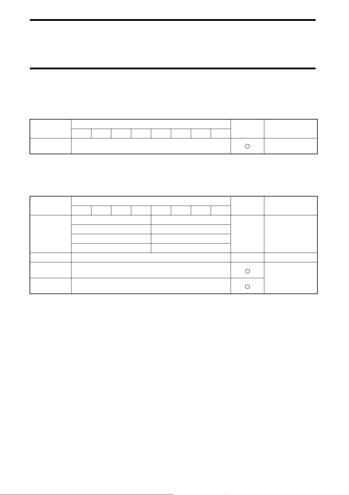
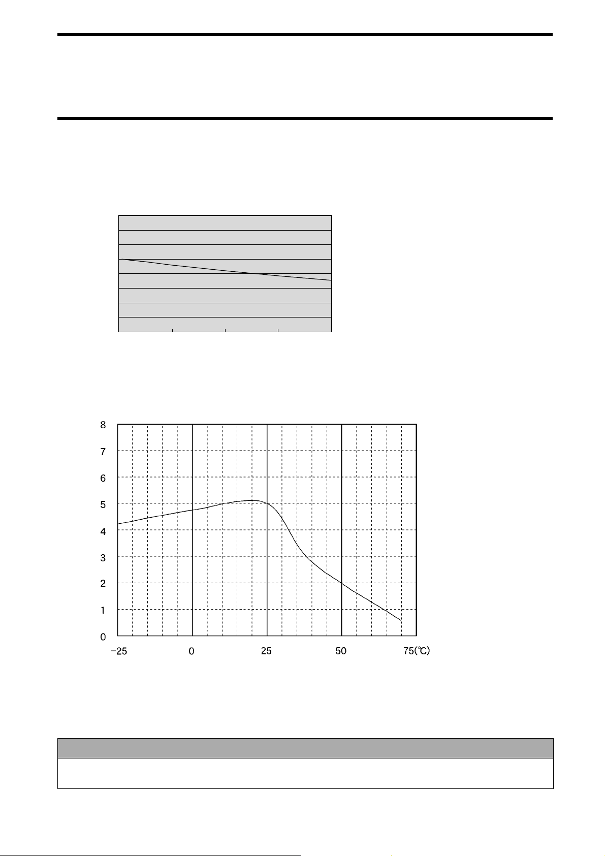
2-2-4 Battery Life Characteristic
The ID tag contains a battery. The charts below show the relation between the ID tag battery life, number of communication bytes and
ambient temperature. The battery life means the time until the b attery voltage alarm has been given.
Communication data and battery life (at the ambient temperature 25°C)
Battery life
(Year)
8
7
6
5
4
3
2
1
0
0246
Communication data k
byte (100 times/day)
Conditions
• Write (single trigger without verification)
•One tag
• The tag is in a sleep mode after a command is
executed.
Example of command
[STX]0080W3SUAA0000 0100
[Written data] [ETX]
8
Battery life
(Year)
Ambient temperature and tag battery life (256 bytes x 100 times/day)
Ambient temperature
2-2-5 Battery Vo ltage Alarm Function
When the voltage of ID tag battery becomes low, "7B" is returned to the termination code when a tag communication command (Read
or Write) is executed.
Correct Usage
After the termination code 7B wa s gene rated, the ID tag ca n be used for approxim ately o ne month in a norma l situa tion.
However, we recommend you to replace the tag with a new one immediately.
2-5
Page 21
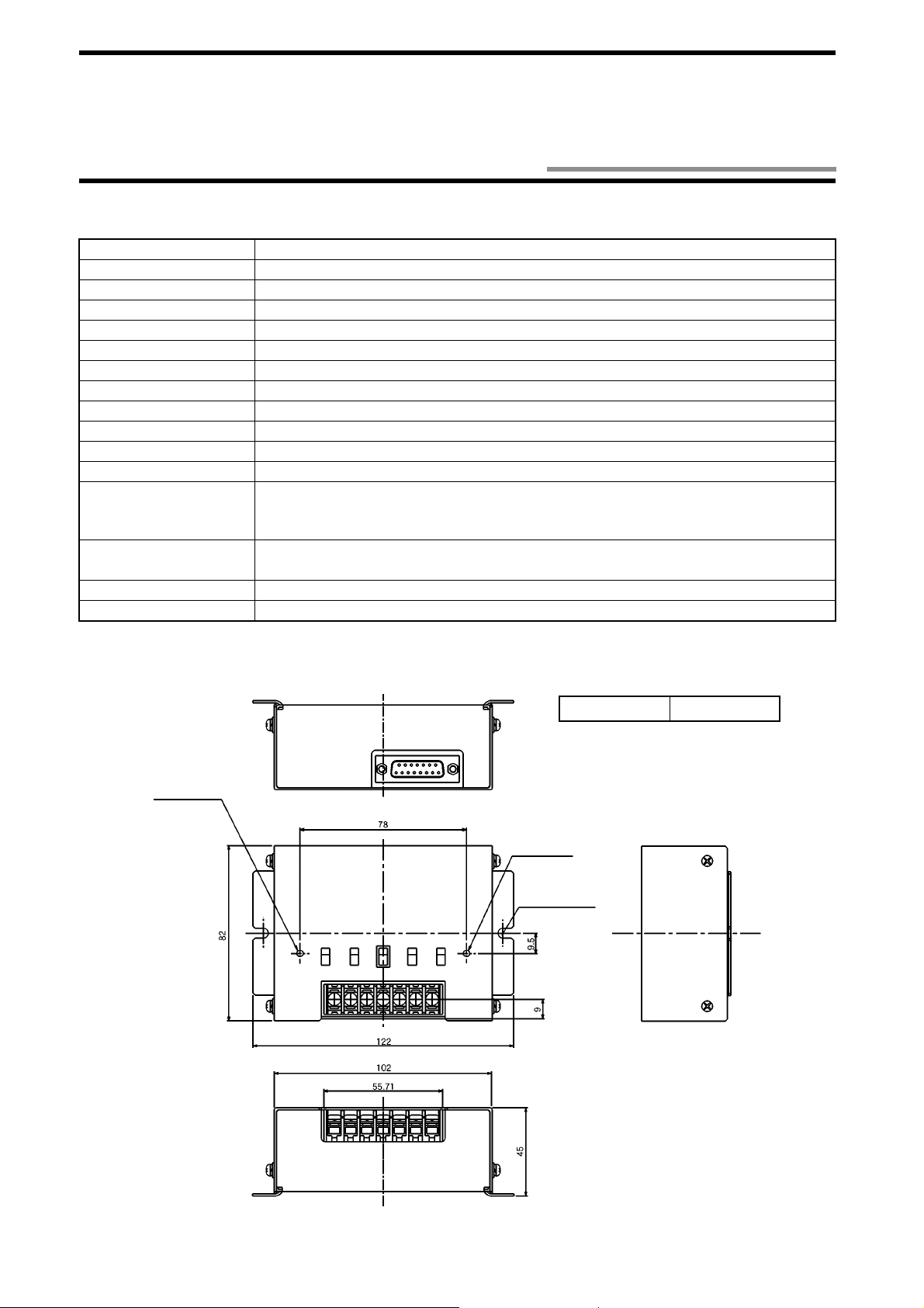
2-3 RS-422A/485 Link Unit Model V690-L01
2-3-1 Specifications
Item Specifications
Interfac e specifications RS- 422A, RS-485
Power supply voltage 24 VDC
Allowable voltage 20.4 to 26.4 VDC
Power consumption 6 W or less
Operating temperature 0 to +55°C (without icing)
Operating humidity 35 to 85%RH (without moisture condensation)
Storage temperature -10 to +65°C (without icing)
Storage humidity 35 to 85%RH (without moisture condensation)
Insulation resistance
Withstand voltage
Protective structure IP30 (IEC60529) * Connected to a connector of the dedicated cable model V690-A5!.
Vibration resistance
Impact resistance
Ground According to Class D.
Weight 450 g or less
20 MΩ or more (at 100 VDC mega). Between a group of cable terminals and a case, excluding GR.
1,000 VAC, 50/60 Hz for 1 minute, detected current 20 mA or less. Between a group of cable terminals and a case, excluding GR.
10 to 150 Hz, single amplitude 0.35 mm, maximum acceleration 50 m/s2. Performing
sweep 10 times for 8 minutes in upward, downward, leftward, rightward, forward and backward directions.
2
Giving impact of 150 m/s
3 times each in upward, downward, leftward, rightward, forward
and backward directions, i.e., 18 times in total.
2-3-2 Outside Dimension
Antenna indicator
Case material SECC (Iron)
Operation indicat or
2-φ4.5 Mounting hole
2-6
(Unit: mm)
Page 22
2-3 RS-422A/485 Link Unit Model V690-L01
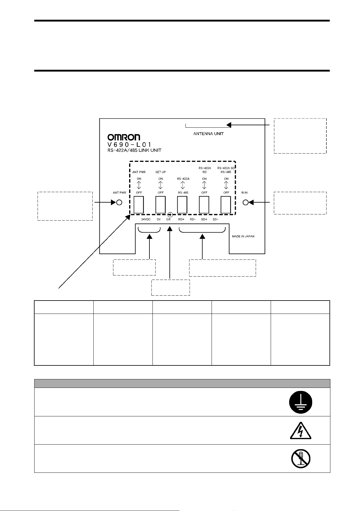
2-3-3 Function
This link unit functions as a relay to operate a host device and antenna thro ugh RS-422A/RS-485 communicatio n. For an example of
internal circuit, refer to Section 4-2-2.
Connect a connector
(D-SUB 15-pin) of the
RS-422A/RS-485 link
unit connecting cable.
Indicator "ANT PWR"
Turns on when 24
VDC is supplied to the
antenna.
Connect 24 VDC
power supply.
Ground accord-
Switch Function
ing to Class D.
ANT PWR SET UP RS-422A/RS-485
By setting it to ON,
the power is supplied to the antenna.
By setting it to ON,
the setting mode terminals "+P" and "-P"
RS-422A and RS485 are switched to
each other.
are short-circuited.
By setting it to OFF,
the power is not supplied to the antenna.
By setting it to OFF,
"+P" and "-P" are dis-
connected from each
other.
Connect a communication
line of RS-422A/RS-485.
RS-422A RD
(Receiving)
For RS-422A, the terminating resistance (220
Ω
) of RS-422A RD
(Receiving) is turned
ON/OFF.
For RS-485, the terminating resistance cannot be turned ON/OFF.
Indicator "RUN"
Turns on when the 24
VDC power supply
turns on.
RS-422A SD
(Sending) RS-485
For RS-422A, the terminating resistance
(220
Ω) of RS-422A
SD (Sending) is
turned ON/OFF.
For RS-485, the terminating resistance
is turned ON/OFF.
Correct Usage
Be sure to connect a grounding wire. Otherwise, an error may occu r in an operation.
Do not touch any terminal when the power supply turns on. Otherwise, an error may occur in an
operation.
Do not disassemble it nor touch the inside when the power supply turns on. Otherwise, trouble
may be caused.
2-7
Page 23
2-4 Connecting Cable
2-4-1 Specifications
Item Specifications
Cable outer diameter 7.5 mm
Cable color Dark gray
Sheathing material Vinyl chloride resin
Number of cores 12 (3 of AWG22 for power supply and GR and 9 of AWG26 for signals)
Insulation resistance 50 MΩ/km or more. Between a group of cables and cable sheath.
Withstand voltage 500 VAC for 1 minute. Between a group of cables and cable sheath.
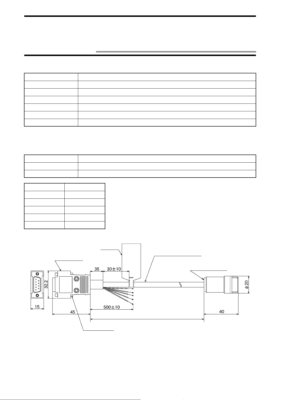
2-4-2 Outside Dimension
(1) RS-232C connecting cable (for IBM PC compatible PC)
Item Specifications
Connector at antenna Round connector (waterproof)
Connector at host device D-SUB 9-pin, female (not waterproof)
Model Cable Length
Model V690-A40 2 m
Model V690-A41 3 m
Model V690-A42 5 m
Model V690-A43 10 m
Model V690-A44 15 m
Connector (at PC)
Connection
label
Inch screw thread (M2.54)
Brown
Blue
Light Green
Black
Green/Yellow
Cable length
Vinyl insulation round cord φ7.5
Connector (at antenna)
(Unit: mm)
2-8
Page 24
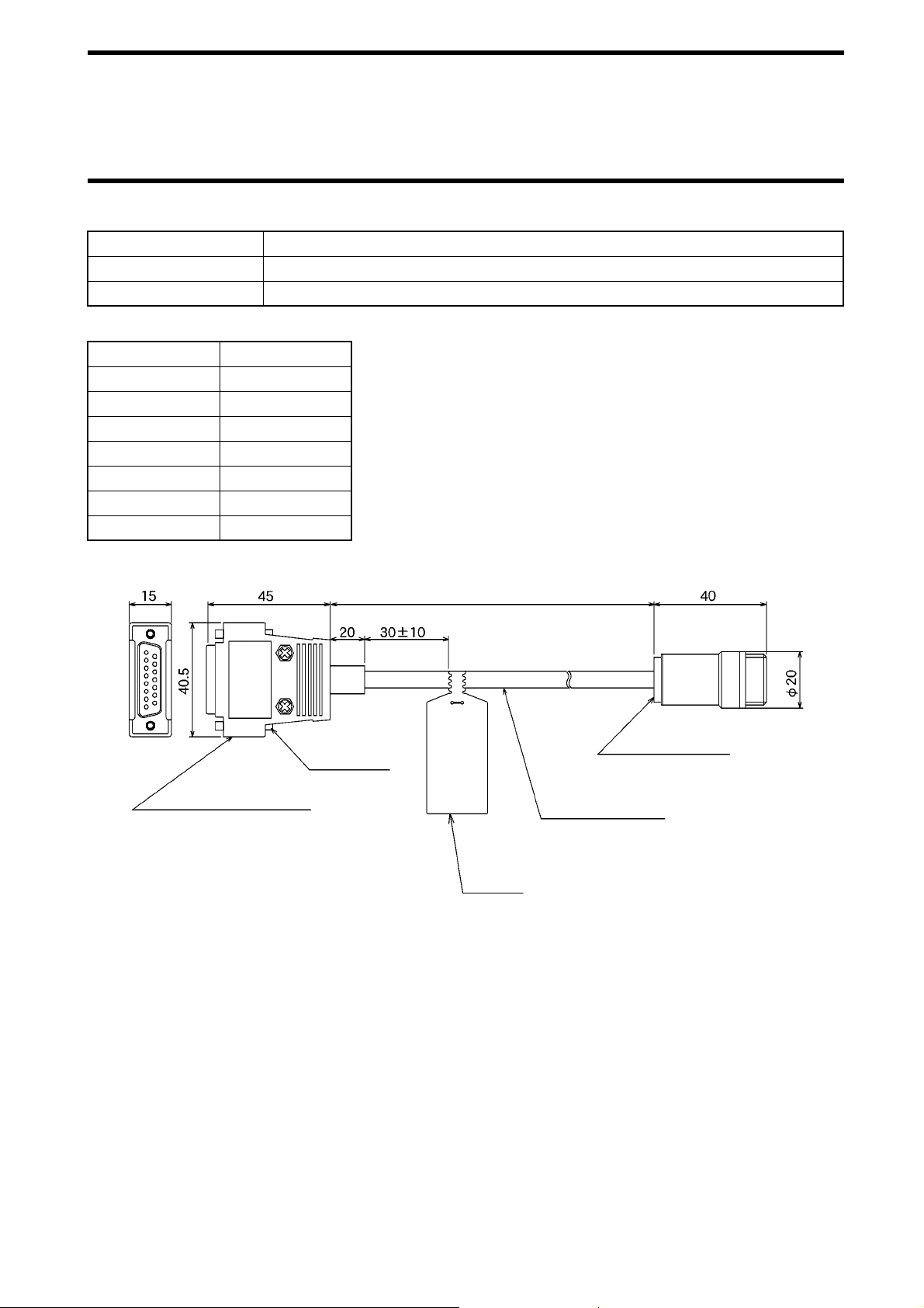
(2) RS-422A/485 link unit connecting cable
Item Specifications
Connector at antenna Round connector (waterproof)
Connector at link unit D-SUB 15-pin, male (not waterproof)
Model Cable Length
Model V690-A50 2 m
Model V690-A51 3 m
Model V690-A52 5 m
Model V690-A53 10 m
Model V690-A54 20 m
Model V690-A55 30 m
Model V690-A56 50 m
2-4 Connecting Cable
Connector (at link unit)
Metric screw
thread (M2.5)
Cable length
Connection
label
Connector (at antenna)
Vinyl insulation round
cord φ7.5
(Unit: mm)
2-9
Page 25
2-5 Communication Performance
Item Specifications
Frequency 2450 MHz band (microwave, 2434.25 - 2465.75 MHz)
Type of radio station Specified low-power radio station - radio equipment for mobile object identification (RCR
STD-29 Version 3.0)
* A user is not required to apply a license for radi o station.
Transmission output at
modulation
Polarized wave Circularly polarized wave
Communication range 2 m mode/5 m mode switched by a host command. (Section 3-2)
Transmission speed 600 kbps
Communication error
check
5 mW for 2 m mode and 10 mW for 5 m mode.
2 m mode: 0.2 to 2.0 m (Reference value)
5 m mode: 0.2 to 5.0 m (Reference value)
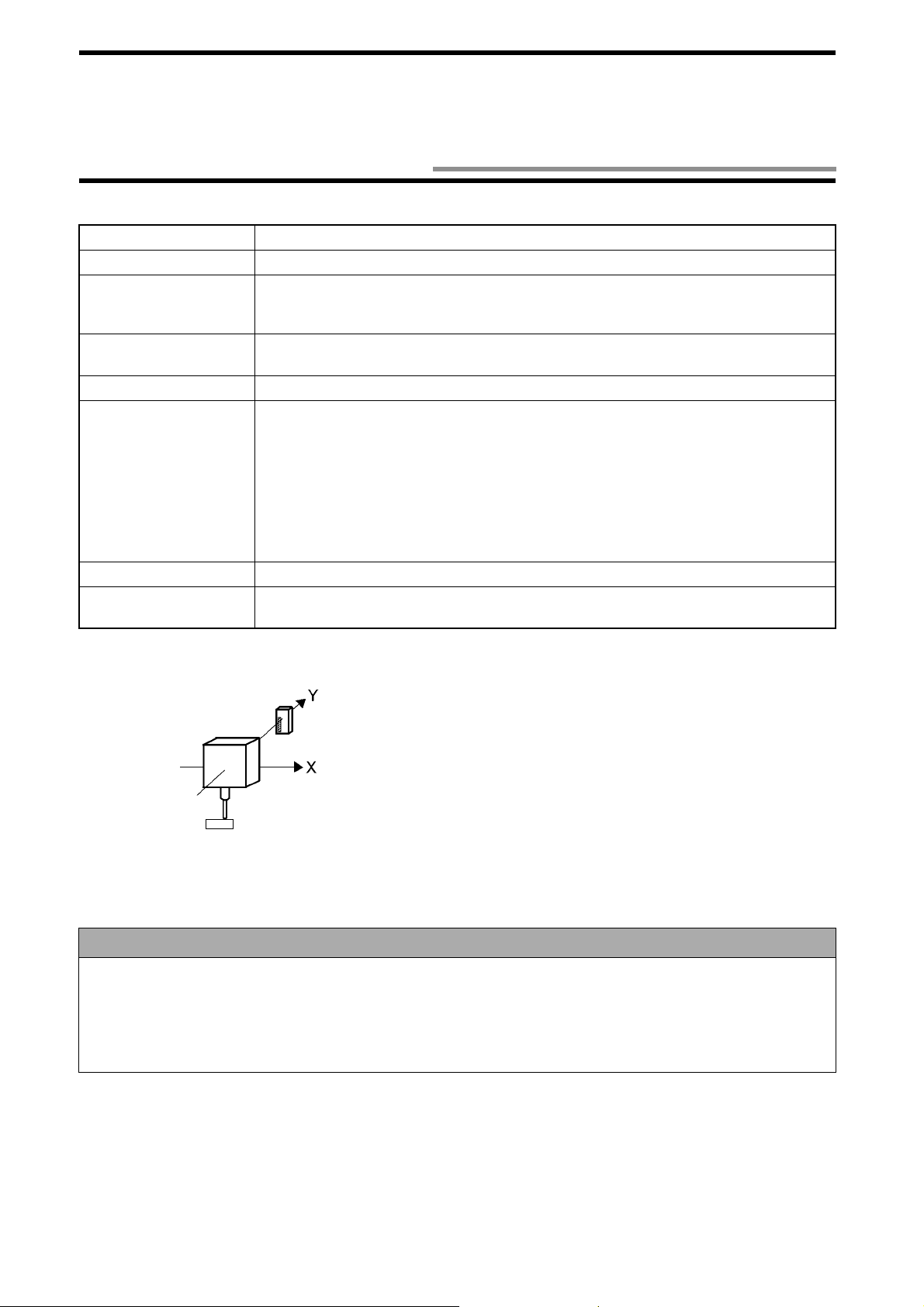
* Conditions for reference value
• Ambient temperature 20±5°C
• Place the tag at a suitable rotating position so that the logo "omron" can become upright.
(Refer to the figure below.)
• On a medial axis of antenna pla ce d at 1.5 m hig h in a larg e room wh ere rad io wav e noi se
is minimized.
CRC 16 bits are used in two ways. (CRC: Cyclic Redundancy Check)
[Tag Rotating angle: 0 degrees]
Antenna
* A hatched area on the tag shows a logo.
• The communicatio n ran ge v ari es d epe nding on the installatio n si te e nv iron me nt. Th is is bec aus e a met al m ate rial and
the ground reflect a radio wave, and water and human body absorb it. Locate an antenna and tag in the communication range and check the radio wave environment in advance.
• The Read/Write antenna model V690-HMG01 has a communication test command to check the radio wave environment at a working site. (Refer to Section 3-5.)
Tag
Correct Usage
2-10
Page 26

2-6 Communication Specifications
Item Specifications Remarks
Reference standard RS-232C
RS-422A
RS-485
Communication method Two-way half-duplex transmission
Transmission speed 4,800 bps, 9,600 bps, 19,200 bps, 38,400 bps,
57,600 bps and 115,200 bps
Synchron ization method Sta rt-stop synchronizati on (Stop bit 1 or 2) Note 2
Transmission code ASCII 7 unit or JIS 8 unit Note 2
Maximum numbe r of con -
nected antennas
Error control Vertical parity (even, odd, nil). Horizontal parity is used as BCC. Note 2
Line length RS-232C: A maximum of 15 m
Note 1. The antenna is eq uipped with RS-23 2C and RS-422A termin als. Refer to Section 2-1-3. RS-422A/4 85 is connect ed through
the link unit.
Note 2. Switched by a command from a host device. (Refer to Section 5- 9-7.)
32
RS-422A: A maximum of 300 m
RS-485: A maximum of 300 m
Note 1
Note 2
2-11
Page 27
Chapter 3 Functions
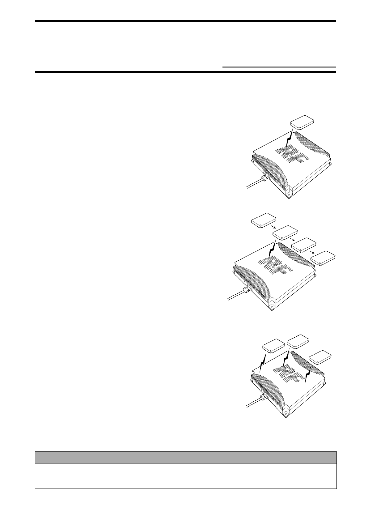
3-1 Single/FIFO/Multi Mode Access Function
You can use one of the three communication modes according to the number of tags in the communi cation area and the situation. The
communication mode can be specified in the communication designation in a command.
(1) Single mode
In the Single mode, the communication is made to one tag in the antenna communication area. In the Sin gle m od e, o nly o ne ta g m u st be p laced in the a n tenn a co mmunication area. If two or more tags are in the antenna communication area, a
communication error occurs.
(2) FIFO mode (First-In First-Out)
The FIFO mode enables to access the t ags coming in the communication area
sequentially one by one. When the communication to one tag has been completed,
the tag is prohibited from communicating. So, even if there is any tag, which
ended the communication, in the antenna communication area, the communication
can be made to the next target tag. When the tag prohibited from communicating
has gone out of the antenn a communication area, such ta g can communicate again.
(3) Multi mode
When there are several tags in th e antenna communication area, the Multi mode
enables to access all those tag s. By using the Selective Access function, the communication can be made to a specified tag of those in the anten na communication
area.
Correct Usage
When you use the FIFO mode, only one tag mus t be plac ed in the a ntenna commu nicat ion area . If two or mo re tags are
in the antenna communi cation area, a c ommu nicati on error oc curs. Then , the comm unica tion ca nnot be recove red f rom
failure unless only one tag is in the antenna communication area.
3-1
Page 28

3-2 Communication 2 m Mode/5 m Mode Switching
The communication 2 m mode and 5 m mode can be switched to each other by a command from a host device. Use either one depending on a working site.
For the command, refer to Sections 5-9-2 and 5-9-3. The default value is the 2 m mode.
For the communication area of 2 m mode and 5 m mode, refer to Section 7-1.
3-2
Page 29
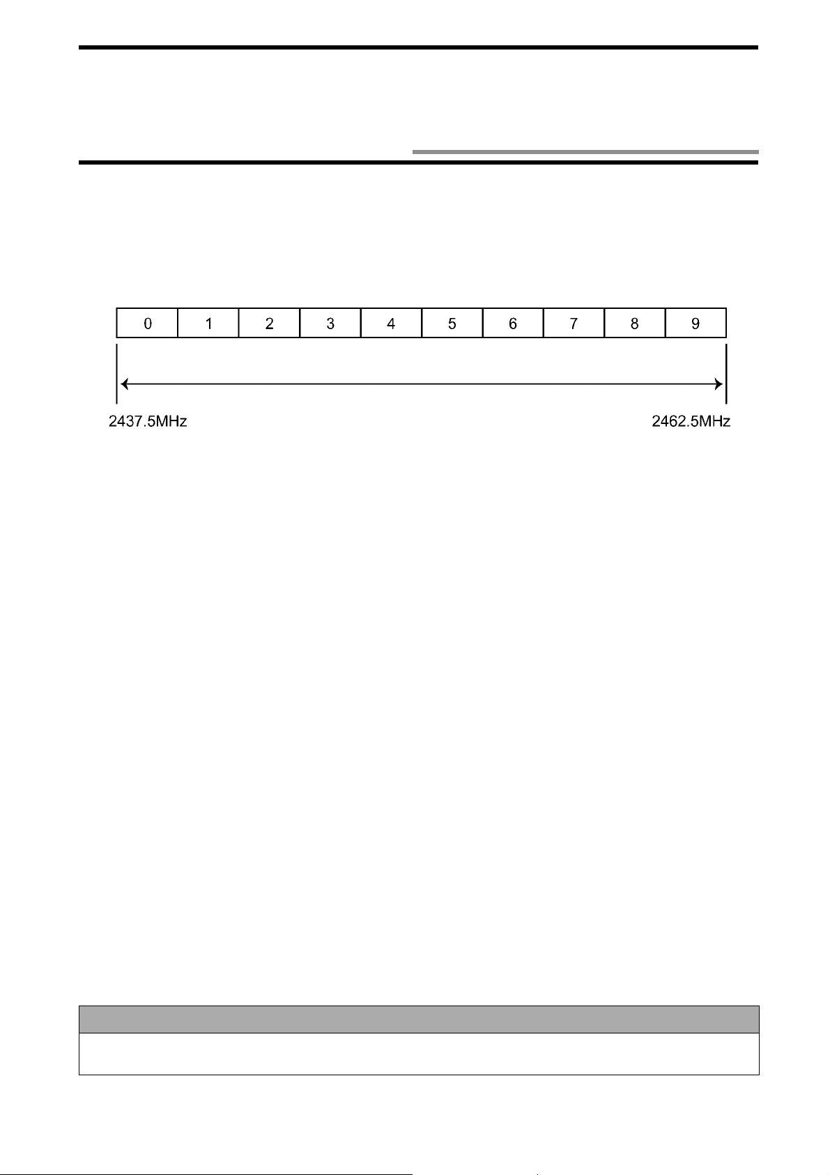
3-3 Radio Wave Channel Switching
In this RFID system, a range from 2437.5 to 2462.5 MHz in the 2450 MHz frequency band can be divided into ten, and 10 channels (at
2.5-MHz intervals) are availa ble. Those channels can be sw itched by a command from a host device. Use them to prevent the mutual
interference between antennas or interference caused by any other devices.
For the command, refer to Sections 5-9-2 and 5-9-3. The default value is Channel 5 (2450 MHz).
Channel
2450 MHz frequency band
Correct Usage
Due to dispersion of frequency, the frequencies of adjacent channels may overlap each other. Do not assign consecutive numbe rs to the chann els of adjacent antennas.
3-3
Page 30
3-4 Simplified Communication Test
You can check the communication between an antenna and tag using the antenna only without connecting to a host device.
In the simplified communication test, the antenna detects the tag at approximately every 2 seconds and, if the tag responds, it turns on
the indicator C.
(1) Turn off the power supply.
(2) Short-circuit the setting terminals "+P" and "-P".
(3) Turn on the power supply. Then, the setting mode is enabled. (Refer to Section 5-1.)
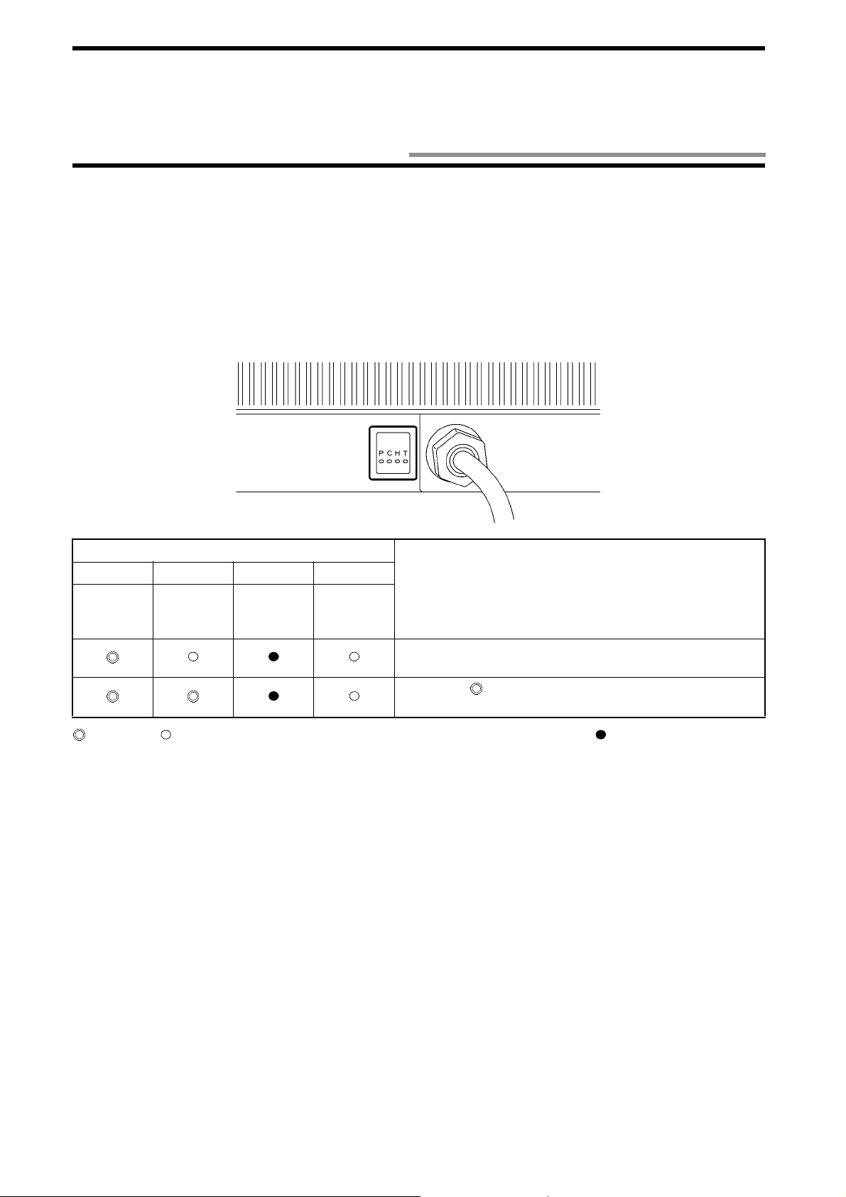
(4) The simplified communication test starts. As shown below, the indicator C (Radio wave emission) shows whether the communica-
tion to the tag is made successfully.
(5) When any command has been sent from a host device to the antenna, the com munication test stops.
Antenna Indicator (Red)
PCHT
Power
supply
Radio
wave
emission
Host trans-
mission
Tag trans-
mission
C and T blink at approximately every 2 seconds. This shows
that there is no tag.
Indication
C turns on ( ). This shows that there is a tag in the antenna
communication area.
: Turns on. : Blinks at approx imately every 2 seconds . (This shows that data is being sent.) : Turns off.
3-4
Page 31

3-5 Communication Test
Execute the communication test to check a radio wave environment at a working site.
Data (256 bytes) is communicated 256 times between the antenna and tag and the communication status is output. A total of 128 kbytes
of data is communicated in two ways. So, it takes a few seconds to execute thi s test. The communicatio n is not retried. Refer to Section
5-7-8.
(1) Create a com mu nication program at a host dev ic e.
(2) Enable the operation mode. (Disconnect the termin als "+P" and "-P" from each other. Refer to Section 5-1.)
(3) Turn on the power supply.
(4) Put the tag in front of the antenna.
(5) Send a commun i cation test command (Section 5-7-8) . If the ant enna is 00, the command is [STX]00 80T0SU[ETX].
(6) If the antenna respo nds to the host device, the communication between the host device and ant enna has been made successfully.
(7) In the re sponse [STX]800 0T0000256 [ETX], a radio wave en vironment val ue is between 0000 and 025 6. If the value i s
close to 0000, the communication to the tag is stable.
Example of response from antenna:
* Radio wave environment is good.
[STX] 8 0 0 0 T 0 0 0 0 2 5 6
Number of Radio wave
communications environment value
* Radio wave environment is poor or no tag is in communication area.
[STX] 8 0 0 0 T 0 0 0 0 2 5 6
Number of Radio wave
communications environment value
0 0 0 0 [ETX]
0 2 5 6 [ETX]
Correct Usage
We recommend you to set the radio wave environment value to 50 or less.
3-5
Page 32

3-6 Write Protect Function
You can enable Write Protect for user data (8 kbytes) per page (256 bytes). Write Protect allows to prevent data being destroyed by
authorized writing.
♦♦♦♦ Scope of Write Protect
The addresses of pages from P0 to P31 are described below.
Page 256 Bytes/page
P0 0000-00FF (h)
P1 0100-01FF (h)
P2 0200-02FF (h)
P30 1E00-1EFF (h)
P31 1F00-1FFF (h)
* (h) means that the value is a hexadecimal number.
♦♦♦♦ How to enable Write Protect
32 Bits of Write Protect data (4 bytes) of system data (refer to Section 2-2-3) correspond to each page. By rewriting a bit corresponding
to a write-protect e d page from 0 (disable) i nto 1 (enable), Write Protect to t he page is enabled. To disable Write Protect, rewrite the bit
from 1 into 0.
Relation betwee n bit of write-prote cted data and page is described below.
256 Bytes x 32 pages =
8192 bytes
Write-Protected Data (4 Bytes)
Code
A1 P7 P6 P5 P4 P3 P2 P1 P0 Status of Write ProA2 P15 P14 P13 P12 P11 P10 P9 P8
A3 P23 P22 P21 P20 P19 P18 P17 P16
A4 P31 P30 P29 P28 P27 P26 P25 P24
P**: Status of Write Protect in page ** (between 0 and 31).
76543210
Bit
Description
tect
0: Disabled (Default
value)
1: Enabled
3-6
Page 33

♦♦♦♦ Example of enabling/disabling Write Protect
A
(1) Enable Write Protect to P3 and P14 in the initial state of the ID tag.
Write-protected data is as follows:
3-6 Write Protect Function
Decimal notation
Hexadecimal
notation
Enables Write Protect to P14
Enables Write Protect to P3
An example of the Write command (Section 5-7-4) is as follows:
Command code
Communication
designation
Split
flag
Data desig-
nation
Start address
Number of written bytes
Response from the antenna at the normal end is as follows:
Command code
Termination code
Response number
ID code
(2) Disable Write Protect to P14, which was enabled in the step (1), and enable Write Protect to P17 and P28.
Write-protected data is as follows:
Enables Write Protect to P28
Decimal notation
Hexadecimal
notation
Enables Write Protect to P17 Disables Write Protect to P14
Written data
An example of the Write command (Se ction 5-7-4) is as follows :
Command code
Communication
designation
Split
flag
Data desig-
nation
Start address
Number of written bytes
Written data
(3) Disable any Write Protect to any page.
Write-protected data is as follows:
Decimal notation
Hexadecimal
notation
n example of the Write command (Section 5-7-4) is as follows:
Command code
Communication
designation
Split
flag
Data desig-
nation
Start address
Number of written bytes
Written data
3-7
Page 34

3-7 ID Tag Power-Saving Function
The tag has the two power-saving functions below.
♦♦♦♦ Function to prevent battery power loss due to radio wave emitted from any other radio
equipment (Enabled always)
If any radio equipment is located near a tag, the tag operates (ready to operate) because the tag’s receiving band is wide. As a result, the
tag battery may be consumed. (Refer to "Not es on Interference to Second-Generation L ow-P ower Data Communication System (Wireless LAN), Cellular Phone, etc." at the beginning of this manual.)
To prevent this power loss, the tag has a function to enter a sleep state (refer to "Appendix 1 - Glossary") against a radio wave emitted
from any other radio equipment.
• The V690 antenna sends a wake instruction (refer to "Appendi x 1 - Glossary" ) at every 10 0 m sec aft er emittin g a radio wave and the
tag operates (ready to operate).
• When the tag receives a radio wave emitted from any other radio equipment, the tag may operate (ready to operate). However, unless
receiving a valid wake instruction, the tag returns to a sleep state in 2 seconds.
Wake instruction
Antenna radio wave emission
Even if there is no command from a host device, the antenna sends a wake
instruction at every 100 msec while emitting a radio wave.
Tag
Tag
Operates (Ready to operate)
Sleep
Operates (Ready to operate)
Sleep
2 seconds (fixed)
If the tag once receives a valid wake instruction in 2 seconds after it started an operation, the tag does not sleep.
2 seconds (fixed)
If the tag cannot receive a valid wake instruction in 2 seconds after it started an operation, the tag sleeps.
3-8
Page 35

3-7 ID Tag Power-Saving Functio n
♦♦♦♦ Function to prevent battery power loss due to neglect when tag works (Enabled always)
When you use the antenna with a repeat command (refer to (3) in Section 5-2-1), due to a trouble in a working site, the tag may be left
in front of the antenna which is emitting a radio wave, although the tag operates (ready to operate). Then, the tag battery is consumed.
To prevent this power loss, the tag has a function to enter a sleep state when a waiting time for sleep (refer to a chart below) has passed.
If the tag cannot receive a valid command within a waiting time for sleep after receiving a valid command, the tag enters a sleep state.
A default value of waiting time for sleep is 480 seconds (8 minutes). To change waiting time, specify "SLEP" as address in the Read/
Write command. (Refer to Sections 5-7-1 and 5-7-3 to 5-7-5.)
To recover the tag from the sleep state:
• Turn OFF the power supply transmission of the antenna and turn ON it again.
• Take the tag out of the communication area and pl ace it in the communication area again.
Antenna radio wave emission
Tag
Operates (Ready to operate)
Sleep
(A radio wave is being emitted)
Command process
Waiting time fo r sle e p
3-9
Page 36

Chapter 4 Installation and Co nn ec tion
4-1 Read/Write Antenna and ID Tag
4-1-1 Installation Environment
(1) Antenna and tag
Install the antenna and tag so that th ose front faces can face each other. Confirm the front side and the reverse side of th em. The front
faces must face each other.
Antenna
Front face
Front face
(2) Antennas
Keep sufficient space between the antennas according to Section 7 -5. If sufficient space cannot be obtained:
• Assign the most different channel numbers to the radio channels of adjace nt antennas. (Refer to Section 3-3 .)
• Permit only one of antennas to transmit a radio wave so that those antennas do not transmit radio waves simultaneously.
(3) Tag rotating position to antenna
The antenna and tag use "circularly polarized wave" as radio wave to communicate with each other. So, the tag can commu nicate with
the antenna at any rotating angle.
The maximum communication range varies de pending on the rotating angle of the tag. Ref er to Section 7-3.
• Conceptual diagram of circ ularly polari zed wave
The arrows show the directions of vibrating surface. The radio wave propagates while the vibrating surface is rotating.
Tag
Antenna
Tag
* A hatched area on the tag shows the "omron" logo.
4-1
Page 37

4-1 Read/Write Antenna and ID Tag
(4) Influence of external objects
• Radio wave absorbers: water, human body, water screen, water-absorptive material, etc.
A radio wave (microwave) penetrates anything (solid body and liqui d) oth er t han me tal, b ut it is a tten ua ted wh ile pe n etra ting . In p arti cular, water absorbs a radio wave extremely. When a radio wave penetrates the water, the radio wave is absorbed considerably. Also, the
radio wave is attenuated rema rkably i n a human body which co ntai ns much wate r. So, any solid bod y and li quid m ust no t exist between
the antenna and tag.
A general-purpose plastic plate with thickness of or glass plate a few millimeters does not absorb the radio wave, and the radio wave
attenuation is not a serious problem in this case. However, the radio wave attenuation varies depending on a type of material and/or
thickness of external objects which the radio wave penetrates. Execute the communication experiment in a working site in advance.
When the communication is performed through the plastic plate or glass plate which absorbs the radio wave so much, such plastic plate
or glass plate may be covered with water due to rain. The radio wave may be attenuat ed by this water screen and the communication
may fail. Execute the communication experiment in a working site in advance and take great care not to get out of the communication
range during an operation.
Dry wood and paper do not a tte nu a te the radio wave so much. However, wo od a nd paper absorb w a te r e as i ly. The wet wood and pa p er
may attenuate the radio wave considerably. Execute the communication experiment in a working site in advance using both of dry
materials and wet ones.
Absorbed in an object and attenuated.
Tag
Radio wave transmitted
from a tag.
Radio wave transmitted
from an antenna
A part of radio wave
is reflected.
Object
• Radio wave reflectors: metal, ground, etc.
Metal reflects a radio wave (microwave) like a mirror reflects light. If there is a metal near an antenna communication area, the communication area is affected by the metal. If a metal is put between an antenna and tag, the communication between the antenna and tag may
fail. Metal, whether metal plate or wire nettin g, may af fec t th e comm unic ation . Also, th e groun d af fe c ts the com muni catio n li ke meta l.
As shown below, a radio wave absorber or reflector can be used to inter rupt a radio wave. When yo u interrupt the radio wave, execute
the communication experiment in a working site in advance.
Example of radio wave absorber: ECCOSOR B AN75 (61 x 61 cm, E&C Engi neering)
Incoming
Communication
area
Outgoing
Radio wave interrupt
4-2
Antenna
Tag that you want to
process data
Tag that you do not want to process data
Page 38

4-1 Read/Write Antenna and ID Tag
• Communication area affected by the ground
If an antenna is installed near the ground, radio waves (microwave) emitted from the antenna and ones reflected by the ground overlap
each other. Therefore, an outline of the communication area becomes ragged and complex. In this case, dead zones may be formed frequently, where no communication can be made to the tag.
Antenna
Tag
Ground
Communication area affected by the ground
Tag
Antenna
Communication area not
affected by the ground
Ground
Correct Usage
Depending on a working site, a special point may be generated in the communication area above and the communication to the tag cannot be ma de a t the point. So, be sure to execute the c om m uni ca tion ch ec k w ith a c om mun ic ati on te st
(refer to Section 3-5), etc.
4-3
Page 39

4-1 Read/Write Antenna and ID Tag
(5) Installation environment
Do not install the antenna and tag at any place below:
• Place where the ambient temperature is out of the range between -20 and +60°C for the antenna and -25 and +70°C for the tag, where
the temperature fluctuates co nsi derably and where moisture condensa tion occurs frequently.
• Place where the relative humidit y is out of the range betw een 35 and 85%RH.
• Place where there is corrosive gas, flammable gas, dust, salt or iron powder.
• Place affected by vi bration or impact.
• Place splashed with water, oil or chemicals
4-1-2 How to Install Antenna
Install an antenna on a flat plane taking care not to bend it by force. As shown below, mount the antenna with four M5 screws, spring
washers and flat washers . Tightening torque is 2.0 N•m (approximately 20 kgf•cm). Do not use any lock pain t to fix screws.
Spring washer
Flat washer
(Unit: mm)
Correct Usage
Do not disassemble it nor touch the inside when the power supply turns on. Otherwise, trouble
may be caused.
4-4
Page 40

4-1 Read/Write Antenna and ID Tag
4-1-3 Rainproofing of Antenna
The antenna is not waterproof structure. So, do not install the antenna.
If you must install the ante nn a o utd oors, p r o tect the antenna against rain with a pl asti c rainp roo f b ox. To p reve nt the water droplet coming in the antenna through a cable, be sure to turn the antenna cable section downward.
Example of plasti c rainproof box: Model WB-5AJ (Outside dimensions: 571 (H) x 412 (W) x 210 (D) mm, Mirai I ndustry)
Gap between the antenna surface and window plate is 10 to 20 mm.
Example of protection box
Cover the window with an
acrylic plate, etc. 3 mm in
thickness which a radio wave
can penetrate easily.
Size enough to cover
the entire antenna
including a connector.
Drill a large hole for ventilation
and drainage.
If the box is metallic, make
a window on the box. The
window size shall be the
same as the antenna.
Clamp it to prevent the connector
being pulled directly.
Correct Usage
Protective structure IP6 2 of the a ntenna is the pr otecti on agai nst the d rop of w ater. If the antenna is splashed with water
spray or water jet flow, cover the antenna with a protection plate. (Refer to "Appendix 3 - Protective Structure".)
4-5
Page 41

4-1 Read/Write Antenna and ID Tag
4-1-4 How to Install Tag
♦♦♦♦ Installation
Install a tag on a flat plane taking care not to bend it by force . As shown below, mount the antenna with two M4 screws, spring washers
and flat washers. Tightening torque is 1.2 N•m (approximately 12 kgf•cm) . Do not use any lock paint to fix screws.
Spring washer
Flat washer
(Unit: mm)
♦♦♦♦ Influence on communication performance, adhesive, metal tape, water screen, etc.
• When you apply adhesi ve, etc. on the tag surface, a radio wave (microwave) is at tenuated and the communication area may be
affected. Execute the communi cation experiment with anythin g used actually in advance.
• If a metallic tape, etc. is put on the tag surface, a radio wave is interrupted and the communication to the antenna fails.
• If the tag is put on a glass plate with double-sided adhesive tape as shown below, a gap between the glass plate and tag sweats easily.
Moreover, a water screen may be ge nerated. In thi s case, please n ote that a radio wave is absorbed and the commun ication range
may become small.
Double-sided adhesive tape, etc.
ID tag
4-6
Glass plate, etc.
Page 42

4-1 Read/Write Antenna and ID Tag
4-1-5 How to Connect Connecting Cable to Antenna
To connect an antenna and host device, use a con necting cable (unbundled ).
RS-232C connecting cable V690-A4! * Refer to Section 2-4.
RS-422A/485 link unit connecting cable V690-A5! * Refer to Section 2-4.
(1) When you co nnect a conn ector o f dedi cated cable and c onnecto r of an tenna, b e sure to h old tho se con nectors and in sert them into
each other completely.
(2) Whe n you have connected th e connectors, turn a ring completely as shown below.
Dedicated cable
Antenna side
Ring
Correct Usage
• Do not connect nor disconnect the connectors when the power supply turns on. Otherwise, a trouble is caused.
• Do not pull the cable by force.
• Do not touch a connecting terminal of the connector.
• Do not touch the connector during an operation.
4-7
Page 43

4-2 How to Wire to Host Device
4-2-1 How to Wire RS-232C Interface
(1) Using RS-232C connecting cable
To connect an antenna and IBM PC compatible machine, use a dedicated RS-232C connecting cable model V690-A4
five electric wires at a connector o f host device as shown below.
RS-232C connecting cable (Model V690-A4!)
!. Connect the
IBM PC compatible
machine
Grounding
according
to Class D
Switch,
etc.
24 VDC
power
supply
•
• Recommendable DC 24 power supply
• •
Model S82K-01524 (Output: 24 VDC, 0.6 A. Input: 100 to 240 VAC.
OMRON)
Connection of leader line of RS-232C connecting cable
Leader line of connecting cable Details of connection
Brown
Thick wire of AWG22
(+) of 24 VDC power supply
Blue (-) of 24 VDC power supply
Light green
Thin wire of AWG26
"+P" and "-P" for the setting mode: Not connected for the operation mode.
Black
Green/Yellow Thick wire of AWG22 Ground according to Class D.
Connector pin layout
Pin
No.
IBM PC Compatible
Machine
Socket (Male) Plug (Female)
1
2 RD (Receiving) TX (Sending)
3 SD (Sending) RX (Receiving)
View of fitting face
4
5
SG (Grounding fo r s ign al) SG (Groun ding for signal)
6
7 RS (Request to send)
8 CS (Clear to send)
9
Antenna
Model V690-HMG01
Short-circuited for the setting mode.
RS-232C Connecting Cable
Model V690-A4!
!
!!
Loop back (Short-circuit)
4-8
Page 44

4-2 How to Wire to Host Device
(2) Using RS-232C connecting cable to extend a cable and connecting to IBM PC compatible machine (typical)
To connect an IBM PC compatible machine (typical) extending a dedicated RS-232C connecting cable, prepare the cables shown below.
Thickness of wire in the cable must be AWG26 or more.
Cable prepared by you
IBM PC compatible
machine
RS-232C connecting cable (Model V690-A4! )
Grounding
according
to Class D
Switch,
etc.
DC 24 V
power
supply
•••• Recommendable 24 VDC power supply
Model S82K-0152 4 (Output: 24 VDC, 0.6 A. Input: 100 to 240 VAC. OMRON)
If you do not use th e r ecommendable power supply or equivalent, co nnect to the 24 VDC power supply via a line filter type GT-205J
(Tokin) or equivalent.
Pin No.
IBM PC Compatible Machine
(Typical)
Socket (Male)
RD (Receiving)
SD (Sending)
Cable prepared by you
Female
Male
RS-232C Connecting Cable
Model V690-A4!
Plug (Fema le)
TX (Sending)
RX (Receiving)
SG (Grounding for signal)
RS (Request to send)
CS (Clear to send)
SG (Grounding for signal)
Loop back
4-9
Page 45

4-2 How to Wire to Host Device
(3) Connecting to OMRON PLC
T o connect an antenna and OMRON programmable controller (PLC), prepare a dedicated RS-232C connecting cable model V690-A4
and connected cable.
Thickness of wire in the cable must be AWG26 or more.
!
OMRON PLC
Pin No.
OMRON PLC
Socket (Female)
SD (Sending)
RD (Receiving)
RS (Request to send)
CS (Clear to send)
Cable prepared by you
Cable prepared by you
Male
Loop back
(Short-circuit)
Female
RS-232C connecting cable (Model V690-A!)
Grounding
according
to Class D
Switch,
etc.
24 VDC
power
supply
RS-232C Connecting Cable
Plug (Female)
TX (Sending)
RX (Receiving)
SG (Grounding for signal)
4-10
Loop back
SG (Grounding for signal)
Page 46

4-2 How to Wire to Host Device
4-2-2 How to Wire When Connecting RS-422A/485
(1) 1:1 connection with link unit
To connect an antenna and host device through RS-422A/485, use the link unit. An example below shows the connecti on of one
antenna and one host device through RS-422A (4-wire).
Microwave
antenna
Station No.
00
Host device
Host device
setting
RS-422A/485 link unit connecting cable
Link unit
24 VDC
ground-
ing
Link unit setting
* RS-422A
(4-wire)
* Terminating
resistance
RD ON
SD ON
* RS-422A
(4-wire)
* Terminating
resistance
RD ON
SD ON
4-11
Page 47

4-2 How to Wire to Host Device
Internal configuration of the 1:1 connection of an antenna and host device through RS-422 A (4 - w ire) is shown below.
• Signal lines (Rx, Tx and SG) of RS-232C are disconnected.
• If RS-422A is selected with the link unit, SD and RD of the terminating resistance (220 Ω) can be turned ON/OFF.
Antenna
RS-422A circuit
Microwave
antenna
Station No. 00
Link unit
RS-422A/485 link
unit connecting
cable
Power sup-
ply circuit
Setting
mode
RS-232C circuit
Grounding
Cut in a connector.
Link unit
4-12
Antenna
power
supply
switch
Setting switch
When switching
RS-422A
Page 48

4-2 How to Wire to Host Device
(2) 1:N connection with link unit
To connect an antenna and host device through RS-422A/485, use the link unit. An example below shows the connecti on of several
antennas and one host device through RS-485 (2-wire).
A maximum of 32 units can be connected
Host device
RS-422A/485 link unit
connecting cable
Microwave
antenna
Station No.
Link unit
24 VDC
ground-
ing
00
Microwave
antenna
Station No.
01
Link unit Link unit
24 VDC
ground-
ing
24 VDC
ground-
Microwave
antenna
Station No.
31
ing
Host device setting
* RS-485
(2-wire)
* Terminating
resistance ON
Link unit setting
* RS-485
(2-wire)
* Terminating
resistance
OFF
Link unit setting
* RS-485
(2-wire)
* Terminating
resistance
OFF
Host device setting
* RS-485
(2-wire)
* Terminating
resistance ON
Correct Usage
Turn ON (connected) the terminating resistances at both ends of the entire RS-422A/RS-485 communication wiring.
4-13
Page 49

4-2 How to Wire to Host Device
Correct Usage
A host device must send the next co mman d in 10 ms after checki ng a respon se from an an tenna. When you use an RS 232C/485 converter, etc. in the host device, the command must be sent after the command transmission has been
enabled completely. When the command has been sent completely, switch into the receiving state within 10 ms. Otherwise, the communication with the antenna may fail.
Host device
Read/Write antenna
Model V690-HMG01
Command frame
(1st time)
Command frame
(2nd time)
Response frame
4-14
Page 50

4-2 How to Wire to Host Device
Internal configuration of th e 1:N connection of an antenna and host device through RS-485 (2-wire) is shown bel ow.
• Signal lines (Rx, Tx and SG) of RS-232C are disconnected.
• If RS-485 is selected with the link unit, the terminating resistance (220 Ω) can be turned ON/OFF.
Antenna
RS-422A circuit
Microwave
antenna
Station No. 00
Link unit
RS-422A/485 link
unit connecting
cable
Power sup-
ply circuit
Setting
mode
RS-232C circuit
Grounding
Cut in a connector.
Link unit
Antenna
power
supply
switch
Setting switch
When switching
RS-485
4-15
Page 51

4-3 Link Unit
4-3-1 Installation Env ironment
♦♦♦♦ Installation site
Do not install the link unit at any place below:
• Place where the amb ient tempe rature is out of t he range betwee n 0 and +55°C, where the temperat ure fluctuates considerably and
where moisture condensation occurs frequently.
• Place where the relative humidit y is out of the range betw een 35 and 85%RH.
• Place where there is corrosive gas, flammable gas, dust, salt or iron powder.
• Place affected by vi bration or impact.
• Place splashed with water, oil or chemicals
♦♦♦♦ Assembly in panel
The ambient operating temperature of link unit is between 0 and +55°C. The following conditions must be met.
• Provide sufficient space for ventilation.
• Do not install the controller near by any heating sources (heater, transformer and large-sized resistance).
• If the ambient temperature rises to 55°C or more, install a ventilating fan or air conditioner to keep the temperature at 55°C or less.
• If you wire a power line (for high current to drive a motor) near the contro l ler, execute the communication experiment fully to check
the influence of noise and wire it with care.
4-3-2 How to Install
Install a link unit on a flat plan e taking care not to bend it by force. As shown below, mount the antenna with two M4 screws, spring
washers and flat washers. Tightening torque is 1.2 N•m (approximately 12 kgf• cm).
Spring washer
Flat washer
(Unit: mm)
4-16
Page 52

4-3 Link Unit
4-3-3 How to Wire
♦♦♦♦ Connecting RS-422A/485 link unit connecting cable
To connect:
(1) When you connect a connector of dedicated cable to the link unit, be sure to hold th e connector and insert it into the link unit com-
pletely.
(2) When you have inserted the cable into the link unit, tighten the two lock screws with the Phillips type screwdriver to fix it.
(3) Fit the connecting cable with a supplied ferrite core. Close the ferrite core and lock it completely.
Ferrite core
Within 10 cm
To disconnect:
(1) To disconnect the connector, loosen the two lock screws completely and pull out it straight holding the connector hood lug.
(2) If it is hard to pull out, push the link unit pulling out the connector.
Correct Usage
Be sure to connect a grounding wire. Otherwise, an error may occu r in an operation.
Do not touch any terminal when the power supply turns on. Otherwise, an error may occur in an
operation.
Do not disassemble it nor touch the inside when the power supply turns on. Otherwise, trouble
may be caused.
4-17
Page 53

4-3 Link Unit
♦♦♦♦ Connecting power supply wire, grounding wire and signal wire
M3 screws are used for the power supply, grounding and signal terminals. For a crimp terminal, use any of terminals below. T ightening
torque is 0.6 N•m (appr oximately 6 kgf•cm).
•••• Applicable crimp terminal
Manufacturer Model Applicable Wire Type
Japan Solderless Terminal 1.25-B3A
Japan Solderless Terminal 1.25-C3A
•••• Recommendable 24 VDC power supply
Model S82K-01524 ( O utput: 24 VDC, 0.6 A. Input: 100 to 240 VAC. OMRON)
•••• Be sure to ground GR according to the Class D.
AWG22 to
AWG16
Fork
(For M3)
(Example of connection)
Grounding according to Class D
Correct Usage
If any noise superposed on the pow er supp ly line is large, sup ply the pow er through a lin e filter. Then, ground noise can
be reduced considerably. Example of line filter: Model GT-205J (Tokin).
4-18
Page 54

4-3 Link Unit
♦♦♦♦ Connecting signal wire
To suppress noise, fit a signal line with a supplied ferrite core as shown below.
(1) Wire the signal wires.
(2) Put the signal wires tog e the r an d w i n d th e s ign a l wi re round the ferrite core. As sh own below , wi n d the s ign a l wir e on c e to prevent
the ferrite core moving. Position the ferrite core within 10 cm from the link unit.
Put the signal wires together.
(3) Close the ferrite core and lock it completely.
To a host device
♦♦♦♦ When you have wired, attach a supplied terminal block cover.
Within 10 cm
Supplied terminal block cover
4-19
Page 55

4-3 Link Unit
4-3-4 Switch Setting
Turn on/off the switches with a supplied plastic screwdriver. By default, all the
switches are set to a lower position (OFF or RS-485).
(Supplied plastic screwdriver)
♦♦♦♦ Enabling the setting mode (Refer to Section 5-1)
(1) Turn OFF the ANT PWR switch (A) referring to the next page.
(2) Turn ON the SET UP switch (B).
(3) Turn ON the ANT PWR switch (A). → The indicator ANT PWR turns on. → Then, the setting mode has been enabled.
♦♦♦♦ Enabling the operation mode (Refer to Section 5-1)
(1) Turn OFF the ANT PWR switch (A) referring to the next page.
(2) Turn ON the SET UP switch (B).
(3) Turn ON the ANT PWR switch (A). → The indicator ANT PWR turns on. → Then, the operation mode has been enabled.
♦♦♦♦ Enabling the RS-422A communication
(1) Turn OFF the 24 VDC power supply of the link unit referring to the next page.
(2) Set the RS-422A/RS-485 switch (C) to RS-422A.
(3) Turn ON or OFF suitably the terminating resistance of RS-422A RD (D) and RS-422A SD (E).
(4) Connect to the signal line terminal.
(5) Turn on the 24 VDC power supply of the link unit.
♦♦♦♦ Enabling the RS-485 communication
(1) Turn OFF the 24 VDC power supply of the link unit referring to the next page.
(2) Set the RS-422A/RS-485 switch (C) to RS-485. → RS-422A RD (D) is disabled.
(3) Turn ON or OFF suitably the terminating resistance of RS-422A SD (E).
(4) Connect to the signal line terminal.
(5) Turn on the 24 VDC power supply of the link unit.
4-20
Page 56

4-3 Link Unit
Connect a connector
(D-SUB 15-pin) of the
RS-422A/RS-485 link
unit connecting cable.
(Model V690-A5!)
Indicator " AN T PWR"
Turns on when 24 VDC
is supplied to the
antenna.
Switch Function
(A) (B) (C) (D) (E)
ANT PWR SET UP RS-422A/RS-485 RS-422A RD
Connect 24 VDC
power supply.
Ground according to Class D.
Connect a communication
line of RS-422A/RS-485.
(Receiving)
Indicator "RUN"
Turns on when the 24
VDC power supply
turns on.
RS-422A SD ( Sending)
RS-485
4-21
Page 57

Chapter 5 Control from Host Device
5-1 Operation Status of Read/Write Antenna and ID Tag
The V690 Series REID system commun i cates with a tag according to the instruction of a command (1) sent from a host device and
returns the result to the host device as the response (3).
Host Device
Communication line
Command
Response
Read/Write antenna
Communication between
the antenna and tag
ID Tag
♦♦♦♦ Operation mode and setting mode of antenna
Two modes are available in the operation of antenna. Available commands vary depending on the mode . Refer to Section 5-4.
Mode How to change mode Description
Disconnect the two antenna
Operation
mode
Setting mode
terminals "+P" and "-P" and
reset the powe r sup ply (turn
off the power supply once
and turn on it again).
Short-circuit the two
antenna terminals "+P"
and "-P" and reset the
power supply.
Use for a normal operation.
• A simplified communication function (without connection to a host
device) is available. Refer to Section 3-4.
• A tag communication command
and radio wave transmission ON/
OFF command cannot be used.
Host communication
condition
Setting can be
changed.
(Refer to Section 5-9-
7.)
Fixed.
(Refer to Section 5-9-
7.)
Use when the host
communication condi-
tion is unknown.
Antenna
station number
00 to 31 (Initial
value 00)
99
♦♦♦♦ Tag status after a command has been executed
Two modes are available after a command has been executed.
Mode How to change mode Description
Sleep state Specify S! or R! in communication desi gn atio n
with a command.
Standby state Specify W! or C! in communic ation design ation
with a command.
• Tag battery power can be saved.
• A tag cannot be started in 0.2 seconds immediately after sleep.
• Use for FIFO (First-In First-Out). Refer to (3) of
Section 5-2-1.
• Use when seve ral comm ands a re e xecut ed con secutively to one tag.
5-1
Page 58

5-2 Communication Operation Sequence
Operation sequence, such as communication to a tag and response return timing, varies depending on the designation with a command.
You need to use properly according to the tag sta tus in an antenna communication area and a ty pe of communication with a host device.
5-2-1 Communication Mode with Command
(1) Trigger
Communication is performed to a tag in an antenna communication area when a command has been received. Therefore, check that the
tag is in the antenna communication area and then execute a co mmand. If there is no tag in the antenna co mmunication area when a
command has been executed, th e ant enna returns an error response.
When a command is executed, the tag is in a sleep mode or standby mode.
• Sleep mode (Comm unication designation SU or SN)
The tag battery power can be saved in the sleep mode. The tag cannot be started in 0.2 seconds immediately after sleep.
• Standby mode (Communication designation WU or WN)
To execute several commands consecutively to one tag, enable the standby mode.
(Host device)
Trigger command
Command process ended
(Antenna) (Tag)
Communication
process
Response
Not yet
approached
Tag
Tag
Sleep or
standby
(1)The host device must check that the tag is
in the antenna communication area and
then execute a command.
(2)The antenna communicates to the tag
according to the command .
(3)When the process has completed, the
antenna returns a response of the process
end to the host device and becom e s ready
to accept a command.
Correct Usage
Trigger, check that a tag is in the antenna communication area.
5-2
Page 59

5-2 Communication Operat ion Sequen ce
(2) Single Auto
An antenna waits until a tag approaches the communication area and then communicates with the tag.
To terminate Single Auto:
• When an auto repeat cancel command (C2) is issued, the antenna discontinues Single Auto and becomes ready to accept a command.
• When any other comma nd is i ssue d, the anten na disco ntinu es Sing le Au to an d e xecut es th e new co mman d. If th e co mmand forma t
is wrong, the antenna returns the format error response 14 and discontinues Single Auto.
• If a waiting time for tag (refer to Section 5-9-4) is set, when the waiting time for tag has been passed, the antenna returns the no-tag
error response 72 and discontinues Single Auto.
When a command is exe c uted, the tag is in a sle e p mode or standby mode.
• Sleep mode (Communication designation SU or SN)
The tag battery power can be saved in the sleep mode. The tag cannot be started in 0.2 seconds immediately after sleep.
• Standby mode (Communication designation WU or WN)
To execute several com mands consecutively to one tag, enable the standby mode.
(Host device)
Single Auto
command
Command process ended
(Antenna) (Tag)
Waits for tag
approaching
Waits for tag
approaching
Communication
process
Response
Not yet
approached
Not yet
approached
Tag
Sleep or
standby
Pass
(1)The Single Auto command is sent from
the host device.
(2)The antenna does not return a response
until the tag approaches. So, the host
device waits for a response.
(3)When the tag passes the front of the
antenna, the antenna communicates with
the tag according to a command.
(4)When the process has completed, the con-
troller returns a response of the process
end to the host device and becomes ready
to accept a command.
5-3
Page 60

5-2 Communication Operation Sequence
(3) Repeat
When an antenna receives a command from a host device, the antenna wai ts for tag approaching, communicates with the tag whenever
the tag passes the antenna comm unication area, and returns a respon se t o the host device.
After the command is executed, by specifying the sleep state (S
!) as the communication designation, FIFO (First-In First-Out . Refer to
Section 3-1) is enabled.
To terminate repeat state:
• When an auto repeat cancel command (C2) is issued, the antenna di scontinues Repeat and becomes ready to accept a command.
• When any other c ommand is issued, the antenna discontinu es Repeat and execut es the new command. If the command form at is
wrong, the antenna returns the fo rm at error response 14 and discontinues Repeat.
If a waiting time for t ag (refer to Sec tion 5-9-4 ) is se t, when the wa iting time for t ag ha s been p assed, t he an tenna re turns the no-tag error
response 72 and continues Repeat.
(Host device)
Repeat command
(Waits for a response)
Receives a
response
(Waits for a response)
(Antenna)
(Waits for tag approaching)
(Waits for tag approaching)
Communication
process
Response
(Waits for tag approaching)
(Tag)
Not yet approached
Not yet approached
Not yet approached
Tag (1)
Sleep
Pass
Pass
(1)The Repeat command is sent from the host device.
(2)The antenna does not return a response until the tag
approaches.
(3)When the tag passes the front of the antenna, the
antenna communicate s with the tag according to a command.
(4) When the process has completed, the antenna returns a
response of the com munication end to the hos t device
and waits for the next tag approaching.
Receives a
response
(Waits for a response)
5-4
Communication
process
Response
(Waits for tag approaching)
Waits for tag
approaching
Tag (2)
Sleep
Pass
Not yet approached
(5) Whe n the tag passes the fro nt of th e antenna again, the
antenna communicates with the tag.
(6) When the process has completed, the antenna returns a
response of the comm unication end to the host device.
Page 61

5-2 Communication Operat ion Sequen ce
5-2-2 Communication Mode with Communication Designation
(1) Polling
When one host device controls several antennas, if a normal auto command is used, a response is returned when the tag communication
has completed. In this case, several antennas return a response. For polling, the antenna returns the response at the request of the host
device. So, some responses are not returned simultaneously and several antennas can be controlled.
To terminate polling:
• When an auto repeat cancel command (C2) is issued, the antenna discontinues Polling Auto/Polling Repeat and becomes ready to
accept a command.
• When any other com mand i s issu ed, t he ant enna d isco ntinu es a pol ling m od e and ex ecu tes the n ew comma nd . If the com man d format is wrong, the antenna returns the format error response 14 and discontinues Polling Auto/Polling Repeat.
• If a waiting time for tag (refer to Section 5-9-4) is set, when the waiting time for tag has been passed, the antenna returns the no-tag
error response 72 and discontinues Polling Auto. For Polling Auto, the antenna returns an error response and continues Polling
Repeat.
When a command is exe c uted, the tag is in a sle e p mode or standby mode accor ding to the communication designation (C!, R!).
5-5
Page 62

5-2 Communication Operation Sequence
(Host device)
Polling Auto command
Station No. 00
Receives a response
Polling Aut o command
Station No. 01
Receives a response
Requests a response
Station No. 00
Receives a response
Requests a r esponse
Station No. 01
Receives a response
Requests a response
Station No. 00
Receives a response
(Antenna)
<Station No. 00>
Polling response
(Waits for tag approaching)
Response of "Not yet
approached"
(Waits for tag approaching)
Communication process
Response
(Tag)
Not yet
approached
Not yet
approached
Tag
Pass
(Antenna)
<Station No. 01>
Polling response
(Waits for tag approaching)
Response of "Not yet
approached"
(Waits for tag approaching)
(Tag)
Not yet
approached
Not yet
approached
(1) The Polling Auto command is sent from
the host device to the antenna station
No. 00.
(2)Immediately after receiving the com-
mand, the antenna returns a response
that the command has been accepted.
(3) The Polling Auto command is sent from
the host device to the antenna station
No. 01.
(4)Immediately after receiving the com-
mand, the antenna returns a response
that the command has been accepted.
(5)The host d evice can in quir e the p r ogre ss
of process using a resp onse request. If
the tag has not yet approached, a
response of "Not yet approached" is
returned to the response request.
(6)When the tag passes the front of the
antenna station No. 00, th e antenna station No. 00 communicates with the tag.
(7) W hen the response reques t is sent to the
antenna which ended the communication with the tag, the antenna returns a
response of proce ss result and becomes
ready to accept a command.
Requests a response
Station No. 01
Receives a response
Response of "Not yet
approached"
(Waits for tag approaching)
Not yet
approached
5-6
Page 63

5-2 Communication Operat ion Sequen ce
(2) Multi
The communication to all the tags in the antenna communication area can be made. Multi Trigger and Multi Repeat commands are
available:
In Multi Trig ger, the antenna communi cates with all t he tags in the c ommunic ation a rea whe n it rec eives a comman d. Whe n the p rocess
has completed, the antenna ret urns the communication end resp onse (termination code 72).
In Multi Repeat, the antenna waits for a tag when it receives a command. The antenna continues to communicate with all the tags coming in the communication area.
To terminate Multi Repeat:
• When an auto repeat cancel command (C2) is issued, the antenna discontinues Multi Repeat and becomes ready to accept a command.
• When any other command is issued, the antenna discontinues Multi Repeat and executes the new command. If the command format
is wrong, the antenna returns the format error response 14 and discontinues Multi Repeat.
If a waiting time for tag (refer to Section 5-9-4) is set, when the waiting time for tag has been passed, the antenn a returns the no-tag error
response 72 and continues Multi Repeat.
When a command is executed, the tag is in a s leep mode according to the communication designation (S!).
An example of Multi Trigger is shown below.
(Host device)
Multi Trigger command
Receives a response
Receives a response
Receives a response
(Antenna)
Communication process
Response
Communication process
Response
"Communication End" response "72"
(Tag)
Tag (0)
Tag (1)
Multi S/M/L
Time Slot method (refer to "Appendix 1 - Glossary") is used to detect several tags. Select S, M or L to optimize the Multi communication time.
Code Number of communicated tags Number of time slots
S
M
L
Approximately 4 tags
Approximately 8 tags
Approximately 16 tags
8
16
32
5-7
Page 64

5-2 Communication Operation Sequence
5-2-3 Other Communication Mode
(1) Selective Access
Every tag has an inherent ID code which cannot be rewritten. By using this ID code, communication can be per formed to a particular
tag of those in an antenna communication area.
Executes ID Code Read (I!)
Refer to Section 5-7-2.
Executes Tag Designation Read command
Refer to Sections, 5-7-3, 5-7-5 and 5-7-7.
Reads an ID code of a tag in the communication area.
Uses an ID code and executes a command to a designated tag.
(2) Radio Wave Transmission ON mode
Usually, an antenna transmits a radio wave after receiving a com mand from a host device. When the Radio Wave Transmission ON
mode of antenna is enabled , reg ardless of any command from a host device, the antenna transmits a radio wave al ways. In the Radio
Wave Transmission ON mode, an application that the ID tag moves fast may be avail able.
Executes Radio Wave Transmission ON (A1)
Refer to Sectio n 5- 9 -1 .
Executes Read/Write
Mode Initial value How to change mode Radio wave transmission status
The antenna does not transmits a radio wave when
Radio Wave
Transmission
OFF mode
it waits for a command. When the antenna accepts
a communication command, the antenna transmits
a radio wave an d c om municate w it h a ta g. When
the communicati on has ended, the antenna stops
transmitting a radio wave.
Radio Wave
Transmission
ON mode
Radio Wave Transmission ON (A1) Refer to
Section 5-9-1.
How to switch to the Radio Wave Transmission OFF mode
• Radio Wave Transmission OFF command
(A0) Refer to Section 5-9-1.
Regardless of any command from a host
device, the antenna transmits a radio
wave always.
• Reset command (C0) Re fe r to Se ct ion 5-9- 2.
• Reset the power supply.
5-8
Page 65

5-3 Communication Response Format
(1) Command
A text section of command consists of a command and option section which specifies information. The antenna receives a range from
STX receiving to ETX correctly and, only when the antenna station No. and DA match, executes a command. After receiving STX,
when the antenna receives STX again by the time the antenna receives ETX, the second STX shall be the beginning of the command.
Y ou can specify whether BCC is enabled or disabled. By default, BCC is disabled. How to specify whether BCC is enabled or disabled,
refer to Section 5-9-7.
• Disabling BCC *A value below shows the number of characters.
Command code
• Enabling BCC
Command code
Name Description
STX Shows the beginn ing of a com mand respon se fram e. It c orresp onds t o 02h ( hexad ecima l num ber)
in the ASCII code table.
DA Destination (antenna) station number. Operation mode "00" to "31" (initial value is "00"). Setting
mode "99". A station number in the operation mode can be changed in "Station Number Setting".
SA Source (host device) station number "80" to "89". Several host device can be used. If only one
host device is used, speci fy "80 ".
Command Code Specifies a command f or anten na ope ration. For avail able com mand codes , refer t o the c omma nd
list in Section 5-4.
Option Specifies the communication of command execution, reading data and writing data. For details,
refer to the formats of commands after Section 5-7.
ETX Shows the end of command response. It corresponds to 03h (hexadecimal number) in the ASCII
code.
BCC Block Check Character (referred to as "BCC"). Calculation result of horizontal parity immediately
after STX to ETX. It is displayed in one character. For example of calculation of BCC, refer to the
next page.
Option
Option
Note: "h" is a hexadecimal notation.
(2) Response
A text section of resp onse consists of a command, termination code and data section.
• Disabling BCC *A value below shows the number of characters.
Command code
Termination code
• Enabling BCC
Command code
Termination code
Data
Data
5-9
Page 66

5-3 Communication Response Format
Name Description
DA Destination (host device) station number "80" to "89".
SA Source (antenna) station number. Operation mode "00" to "31" (initial val ue is " 00"). Se tting mode
"99".
Command Code Returns a command code of sent command.
Termination Code Responds the result of command ex ecution as a termination code . For the termination code , refe r
to the termination code list in Section 5-10.
Data Responds a response number, ID code, read data, etc. For details, refer to the formats of com-
mands after Section 5-7.
♦♦♦♦ Example of calculation of BCC
Use to detect data error due to noise in data communication be tween a host dev ice and antenna . BCC is one-characte r data that XOR of
every data was executed per character in a range from DA to ETX. For details, refer to "JIS5001 Character Configuration on Transmission Line and Horizontal Parity Usage".
An example of calculation is described below.
Example: ID Code Read, Single Trigger
Data
Name
Data 02h “00” “80” “I3” “W” “U” 03h 73h
Note: "h" is a hexadecimal notation.
DA 0 0011 0000
SA 8 0011 1000
Command Code I 0100 1001
Communication Designation W
ETX 03H 0000 0011
STX DA SA
00011 0000
00011 0000
3 0011 0011
U 0101 0101
Command
Code
XOR
XOR
XOR
XOR
XOR
XOR
0101 0111
XOR
XOR
Communication Desig-
nation
ETX BCC
5-10
0111 0011
7h 3h
Page 67

5-4 Communication and Communication Designation List
There are three types of commands as follows:
(1) Tag communication command: A command to communicate with a tag
(2) Antenna operation command: A command to operate an antenna when communicating with a tag.
(3) Antenna setting command: A command to set an antenna before operating a system.
(1) Tag communication command
Use this command when an ante nna is in an operation mode. This command cannot be used in a setting mode. Refer to Section 5-1.
Command
Command
Read
(Sections 5-7-1 and
5-7-3)
ID Code Read
(Section 5-7-2)
Write Without Verification
(Sections 5-7-4 and
5-7-5)
Write With V erification
(Sections 5-7-4 and
5-7-5)
Data Fill
(Sections 5-7-6 and
5-7-7)
Communication Test
(Section 5-7-8)
Communication Mode
(Sections 5-2-1)
Trigger R3
Single Auto R6
Repeat R9
Trigger I3
Single Auto I6
Repeat I9
Trigger W3
Single Auto W6
Repeat W9
Trigger W1
Single Auto W4
Repeat W7
Trigger F3
Single Auto F6
Repeat F9
Trigger T0 Communication test between an antenna and tag.
Command Code Function
Reads data, Write Protect setting, date of production and waiting time for sleep.
Reads an ID code of tag.
* The ID code is a value inherent to tag and cannot
be rewritten.
Writes data, Write Protect setting and waiting time
for sleep.
Writes data, Write Protect setting and waiting time
for sleep. Reads and checks written data after writing.
Writes a fixed data into a sp ecifi ed ar ea in me mory.
For example, by writing "0" into all area s in memory,
everything is cleared.
Communication designation
One tag / Multi (several
Direct respo nse / Polling
((1) in Section 5-2-2)
Direct response One tag Sleep S U
Direct response One tag Standby W U
Polling One tag Standby C U
Direct response Multi (sever al tags) Sleep S S/M/L
Polling Multi (several tags ) Sleep R S/M/L
Direct response Tag designation Sleep S N
Direct response Tag designation Standby W N
* Di rect response: A co mmunicatio n mode that a co mmand is recei ved from a host d evice and a res ponse is m ade immediat ely after
the command execution.
Communication designation (1) W: Direct response. A tag after execution is in a standby state.
Communication designation (2) U: One tag access without ID code designation.
tags) / Tag designation
((2) in Section 5-2-2 and
(1) in Section 5-2-3)
S: Direct response. A tag after execution is in a sleep state.
C: Polling. A tag after execution is in a standby state.
R: Polling. A tag after execution is in a sleep state.
N: One tag access with ID code designation.
S/M/L: Several tag access.
Tag status after com-
mand execution
(Section 5-1)
Communication designation
(1) (2)
5-11
Page 68

5-4 Communication and Communication Designation List
Several tag access S/M/L
The time slot method is used to detect several tags. Select S/M/L to minimize the communication time of Multi. (Even if the number
specified in S/M/L and the number of actual tags do not match, the Multi communication can be made. However, it may take a long
time to communicate.)
Symbol
S
M
L
(2) Antenna operation command
Any command to operate an ant enna is executed immediately.
Number of estimated tags in
communication area at a time
Approximately 4 tags.
Approximately 8 tags.
Approximately 16 tags.
Number of time slots
8
16
32
Command Name
(Referred item)
Auto Repeat Cancel
(Section 5-8-1)
Reset (Section 5-8-2) C0 E nab led
Request to Respond
(Section 5-8-3)
Request to Retransmit (Section 5-8-4)
Command
Code
C2
H0 Requests a response from a tag during polling.
H1 Enabled Requests to retransmit the immediately preceding
Operation
Mode
Enabled
Setting
Mode
Function
Cancels and disables Auto and Repeat commands.
• Clears data read from a t ag at po lli ng. A respo nse
is not returned by the Request to Response (H0)
command.
• Clears the immediately preceding response. A
response is not returned by the Request To
Retransmit (H1) command.
• Changes the Radio Wave Tr an sm is si on O N mod e
into the OFF mode.
• Enables the host communication condition setting
and station number setting commands.
response.
5-12
Page 69

5-4 Communication and Communication Designation List
(3) Antenna setting command
Any command to set an antenna is executed immediately.
Command name
(Referred item)
Radio Wave Transmission OFF (Section 5-9-1)
Radio Wave Transmission
ON (Section 5-9-1)
Communication Range
Selection (Section 5-9-2)
Radio Wave Channel
Selection (Section 5-9-2)
Radio Wave Output Status Read (Section 5-9-3)
Setting of Time to Wait
Tag (Section 5-9-4)
Command Data
Response Time Setting
(Section 5-9-5)
Read Data Length Setting
(Section 5-9-6)
Host Communication
Condition Setting
(Section 5-9-7)
Station Number Setting
(Section 5-9-8)
Setting Read
(Section 5-9-9)
Note 1. To enable "Host Communication Condition Setting" and "Station Number Setting", you must issue a reset command (Section
5-8-2) or reset the power supply after issuing a command.
Note 2. 9.6 kbps, data length 7 bits, even parity, stop bit 2, no BCC. (Refer to Section 5-9-7)
Operation
mode
A0
A1
A4
A5 Selects a radio wave channel (0 -
A6 Reads a communication range
T4
Enabled
H4
H3
H5
H6
M2
Setting
mode
Disabled
Enabled
After resetting power
supply or executing reset
No change in the radio
wave OFF mode.
Return s to th e radio
wave OFF mode.
Setting before
resetting does
not change.
Enabled (Note 1)
Disabled Reads an antenna setti ng val u e .
Selects the radio wave transmis sion OFF mode.
Selects the radio wave ON mode.
Selects the range selection mode
(2 m/5 m).
9).
mode and radio wave channel.
Sets a waiting time for communication with
a tag after command ex ecution when executing Auto or Repeat command.
Sets a command response time,
data response time intervals.
Sets maximum data length which
can be returned by one re spon se of
data read command.
Sets conditions of comm unic ation
with a host device.
Sets an antenna station number. 00
Function
Initial
value
OFF
mode
2 m
mode
5
(2450 MHz)
Unlimited
10 ms
10 ms
256 bytes
27E200
(Note 2)
5-13
Page 70

5-5 Data Code Designation
You can specify a type of code used to transmit data to be read or written between a host device and Read/Write antenna.
ASCII code designation and hexadecimal code designation are available.
♦♦♦♦ ASCII code (JIS 8 unit code) designation "A"
1 byte of data of tag is t ransm itted directly as ASCII code or JIS 8 u ni t cod e . Transmitted one charac te r is e qua l to a 1 by te of data in
a tag. Character data can be read/written directly.
Do not use any control code, such as [SOH] and [CR], in transmission data. Otherwise, a command error occurs.
<Example 1 of writing>
When "OMRON" is specified in 5 bytes of memory beginning with 10h (hexadecimal number) as writing data, data is written into tag
memory as shown below.
Command
STX DA SA Command code
00 80 W1 SU A A 0010 0005 OMRON
Communication designation
Split flag Code designation Start address Number of written bytes Written data ETX
Response
STX DA SA Command code Termination code Response number ID code ETX
80 00 W1 00 01
ASCII code designation
∗∗∗∗∗∗∗∗
Address
Address
Tag Memory
Tag Memory
<Example 1 of reading>
In this data shown here, when 5 bytes of memory beginning with 10h (hexadecimal number) is read out, the read data is "OMRON".
Command
STX DA SA Command code
00 80 R3 SU A A 0010 0005
Communication designation
Split flag Code designation Start address Number of read bytes ETX
Response
STX DA SA Command code
80 00 R3 00 01
Termination code Response number
ID code Split flag
********
A A 0010 0005 OMRON
Code designation
Start address
Number of read bytes
Number of read data
ETX
<Example 2 of writing>
When "1234" is specified in 4 b ytes o f m emo ry be gin ni ng with 10 h (he x adeci mal n umb er ) as wri tin g d ata, data is wri tte n i nto tag me m ory as shown below.
Command
STX DA SA Command code
00 80 W1 SU A A 0010 0004 1234
Communication designation
Split flag Code designation Start address Number of written bytes Written data ETX
Response
STX DA SA Command code Termination code Response number ID code ETX
80 00 W1 00 01
ASCII code designation
Address
∗∗∗∗∗∗∗∗
5-14
Tag Memory
Page 71

5-5 Data Code Designation
<Example 2 of reading>
In this data shown at the previous page, when 4 bytes of memory beginning with 10h (hexadecimal number) is read out, the read data is
"1234".
Command
STX DA SA Command code
00 80 R3 SU A A 0010 0004
Communication designation
Split flag Code designation Start address Number of read bytes ETX
Response
STX DA SA Command code
80 00 R3 00 01
Termination code Response number
ID code Split flag
********
A A 0010 0004 1234
Code designation
Start address
Number of read bytes
Read data ETX
♦♦♦♦ Hexadecimal code designation "H"
1 byte of data of tag is converted into two hexadecimal numbers ("00" to "FF") and those numbers are transmitted. Transmitted two
characters are equal to 1 byte of data in a tag. Be sure to specify written data in two hexadecimal numbers from "00" to "FF" (even).
If any odd number data is specified, a command error occurs.
<Example of writing>
When "1234" is specified in 2 by te s of mem ory b egin nin g with 20 h (h exad ecim al n um ber) as writ ing d ata, da ta is written into tag memory as shown below.
Command
STX DA SA Command code
00 80 W1 SU A H 0020 0002 1234
Communication designation
Split flag Code designation Start address Number of written bytes Written data ETX
Response
STX DA SA Command code Termination code Response number ID code ETX
80 00 W1 00 01
Hexadecimal code designation
∗∗∗∗∗∗∗∗
Address
Tag Memory
<Example of reading>
In this data shown here, when 2 bytes of memory beginning with 20h (hexadecimal number) is read out, the read data is "1234".
Command
STX DA SA Command code
00 80 R3 SU A H 0020 0002
Communication designation
Split flag Code designation Start address Number of read bytes ETX
Response
STX DA SA Command code
80 00 R3 00 01
Termination code Response number
ID code Split flag
********
A H 0020 0002 1234
Code designation
Start address
Number of read bytes
Number of read data
ETX
5-15
Page 72

5-6 Communication Response Flow
Depending on a type of command and the comm un i c at i on d es ignation, the co m ma n d transmission f r o m a h os t device to an an te nn a a nd
the response from the antenna to the host device vary.
(1) No response
When the host device issues a reset command to the antenna, the antenna does not send any response, performs resetting and waits for a
command.
Host Device
Antenna
Reset Command
Execution of Resetting
(2) One to one
When the host device issues Single Trigger and Singl e Auto of a tag communication command, or when the h ost device issued an
antenna operation command and antenna setting command, the antenna returns one response per command.
Host Device
Antenna
Command
Response
(3) Several responses
When the host device issues Single Repeat, Multi Trigger and Multi Repeat, the antenna returns several responses per command.
Host Device
Antenna
Command
Response
Response
Response
Response
5-16
Page 73

5-7 Tag Communication Command
5-7-1 Read
Reads data from a tag.
<Command Format> * A figure below shows the number of characters.
(BCC)
* It can be specified whether BCC is enabled or disabled.
Initial value "00"
Command
Communi-
code
cation des-
ignation
DA
SA
Command code
Communication designati on
Split flag
Code designation
Start address Number of
read bytes
Destination (antenn a) s tation number. "00" to " 31" . Thi s ca n b e
modified in "5-9-8 Station Number Setting".
Source (host device) station number. "80" to "89". If only one host device is used, specify "80".
Specify according to the table below.
Split flag Specify "A".
Specify whether data read out of a tag is ASCII code or hexadecimal code.
Code designation
A: ASCII code
H: Hexadecimal code
Start address
Number of read bytes
Specify according to the table below.
Command code and communication designation
Command
Tag status aft er
execution
Single Trigger Sleep
Single Trigger Standby WU
Multi Trigger (app rox im ate ly 4 tags )
Multi Trigger (app rox im ate ly 8 tags ) SM
Sleep
Command
code
R3
Communica-
tion designation
SU
SS
Remarks
Any other command c an be ex ecuted to the tag imm e diately after it.
Multi Trigger (app rox im ate ly 16 tags ) SL
Single Auto Sleep
Single Auto
Polling Single Auto CU
Standby
R6
Single Repeat
SU
WU
Any other command can be executed to the tag immediately after it.
SU FIFO
Multi Repeat (approximate ly 4 tags ) SS
Multi Repeat (approximate ly 8 tags ) SM
Multi Repeat (approximate ly 16 tags ) SL
Polling Single Repeat RU For a query command of polling, refer
Polling Multi Repeat (approximately 4 tags)
Polling Multi Repeat (approximately 8 tags)
Polling Mult i Repeat (approximately 16 tags)
Sleep R9
RS
RM
RL
to "5-8-3 Request To Respond".
Start address, number of read bytes
Read content Start address
Reading start address
Data
("0000" to "1FFF")
* Hexadecimal number
ASCII code Hexadecimal code
Specify the number of read bytes
("0001" to "2000")
* Hexadecimal number
Number of read bytes
Specify the number of read bytes
("0001" to "2000")
* Hexadecimal numb er
Write Protect setting "WPRO" Unavailable "0004" * Refer to Section 3-6.
Date of production "DATE" "0008" * Refer to Section 2-2-3.
Waiting time for sleep "SLEP" "0004" * Refer to Section 3-7.
5-17
Page 74

5-7 Tag Communication Command
<Response Format> * A figure below shows the number of characters.
DA
Command
code
Termina tion
code
Split flag
Code designation
Response
number
ID code
Start address Number of
read bytes
Read data
Specified number
Destination (host device) station number. * In the command format, the destination is an
antenna.
(BCC)
* It can be specified whether BCC
is enabled or disabled.
SA Source (antenna) station number.
Termination code "00": For a normal end. For any other termination codes, refer to "5-10 Termination Code
List".
Response number Consecutive number of response of tag. For one response, only "01". For several
responses, "02" or more.
ID code ID code of tag. This is inherent to tag and cannot be rewritten.
"Data read length" can be set in an antenna (Refer to Section 5- 9-6). An ini tial value is 256
bytes.
Split flag
• If number of read bytes ≤ data read length, the flag is "A".
• If number of read bytes > data read length, the flag is divided and sent to a host and several responses are made.
"T" for data start. "C" for data continuation. "E" for final data.
Data read out of a tag. Number of characters of data is as follows:
Read data
ASCII code is specified: Number of read bytes.
Hexadecimal code is specified: Number of read bytes x 2.
<Polling Response Format> * A figure below shows the number of characters.
Response immediately after a polling command is issued.
Command
code
Termination
code
(BCC)
* It can be specified whether BCC is enabled or disabled.
Termination code Fixed to "00".
Correct Usage
For an available range of number of read bytes, check the ID tag memory capacity.
5-18
Page 75

5-7-2 ID Code Read
Reads an ID code from a tag. The ID code is inherent to a tag and cannot be rewritten.
<Command Format> * A figure below shows the number of characters.
Command
code
Communication designa-
tion
(BCC)
* It can be specified whether BCC is enabled or disabled.
5-7 Tag Communication Command
DA
SA
Destination (antenna) station number. "00" to "31". This can
be modified in "5-9-8 Station Number Setting".
Source (host device) station number. "80" to "89". If only one host device is used, specify "80".
Command code
Communication designati on
Specify according to the table below.
Command code and communication designation
Command
Tag status aft er
execution
Command
code
Communi-
cation des-
ignation
Single Trigger Sleep
Single Trigger Standby WU
Multi Trigger (app rox im ate ly 4 tags )
Multi Trigger (app rox im ate ly 8 tags ) SM
Sleep
I3
Multi Trigger (app rox im ate ly 16 tags ) SL
Single Auto Sleep
Single Auto
Standby
I6
WU
Polling Single Auto CU
Single Repeat
Multi Repeat (approximate ly 4 tags ) SS
Multi Repeat (approximate ly 8 tags ) SM
Multi Repeat (approximate ly 16 tags ) SL
Polling Single Repeat RU
Sleep I9
Polling Multi Repeat (approximately 4 tags)
Polling Multi Repeat (approximately 8 tags)
RM
Polling Mult i Repeat (approximately 16 tags)
Initial value "00"
Remarks
SU
Any other command can be executed
to the tag immediately after it.
SS
SU
Any other command can be executed
to the tag immediately after it.
SU FIFO
For a query command of polling, refer
to "5-8-3 Request to Respond".
RS
RL
<Response Format> * A figure below shows the number of characters.
(BCC)
* It can be specified whether BCC is enabled or disabled.
DA
Command
code
Termination
code
Response
number
ID code
Destination (host devic e) station number. * In the command format, the destination is an antenna.
SA Source (antenna) station number.
Termination code
Response number
"00": For a normal end. For any other termination codes, refer to "5-10 Termination Code List".
Consecutive number of response of tag. For one response, only "01". For several
responses, "02" or more.
ID code ID code of tag. This is inherent to tag and cannot be rewritten.
5-19
Page 76

5-7 Tag Communication Command
<Polling Response Format> * A figure below shows the number of characters.
Response immediately after a polling command is issued.
Command
code
Termination
code
(BCC)
* It can be specified whether BCC is enabled or disabled.
Termination code Fixed to "00".
5-20
Page 77

5-7-3 Tag Designation Read
Reads data from a particular ID tag.
<Command Format> * A figure below shows the number of characters.
5-7 Tag Communication Command
Split flag
Code designation
Start address Number of
DA
SA
Command
code
Communication des-
ignation
ID code
Destination (antenna) station number. "00" to "31". This can
be modified in "5-9-8 Station Number Setting".
Source (host device) station number. "80" to "89". If only one host device is used, specify "80".
Command code R3: Single Trigger
Communication
designation
Gives communication designation to a tag.
SN: A tag will be in a sleep state after execution.
WN: A tag will be in a standby state after execution.
ID code Specify an ID code of a particular tag.
Split flag Specify "A".
Specify whether data read out of a tag is ASCII code or hexadecimal code.
Code designation
A: ASCII code
H: Hexadecimal code
Start address
Specify according to the table below.
Number of read bytes
read bytes
(BCC)
* It can be specified whether BCC is
enabled or disabled.
Initial value "00"
Start address, number of read bytes
Number of read bytes
Read content Start address
ASCII code Hexadecimal code
Data
Reading start address
("0000" to "1FFF")
* Hexadecimal number
Specify the numbe r of read by tes
("0001" to "2000")
* Hexadecimal number
Specify the number o f read bytes
("0001" to "2000")
* Hexadecimal numb er
Write Protect setting "WPRO" Unavailable "0004" * Refer to Section 3-6.
Date of production "DATE" "0008" * Refer to Section 2-2-3.
Waiting time for sleep
"SLEP" "0004" * Refer to Section 3-7.
5-21
Page 78

5-7 Tag Communication Command
<Response Format> * A figure below shows the number of characters.
DA
Command
code
T erm inati on
code
Split flag
Code designation
Response
number
ID code
Start address Number of
read bytes
Read data
Specified number
Destination (host device) station number. * In the command format, the destination is an
antenna.
(BCC)
* It can be specified whether BCC
is enabled or disabled.
SA Source (antenna) station number.
Termination code "00": For a normal end. For any other termination codes, refer to "5-10 Termination Code
List".
Response number Fixed to "01".
"Data read length" can be set in an antenna (Refer to Section 5- 9-6). An ini tial value is 256
bytes.
Split flag
If number of read bytes ≤ data read length, the flag is "A".
If number of read bytes > dat a read length , the fla g is div ided and s ent to a host and se veral
responses are made.
"T" for data start. "C" for data continuation. "E" for final data.
Data read out of a tag. Number of characters of data is as follows:
Read data
ASCII code is specified: Number of read bytes.
Hexadecimal code is specified: Number of read bytes x 2.
Correct Usage
• Before executing this command, you need to use an ID code read command (I!) to check the ID code of the tag.
• For an available range of number of read bytes, check the ID tag memory capacity.
5-22
Page 79

5-7-4 Write
Writes data into a tag.
<Command Format> * A figure below shows the number of characters.
5-7 Tag Communication Command
(BCC)
* It can be specified whether BCC is
enabled or disabled.
Initial value "00"
Command
Communi-
code
cation des-
ignation
DA
SA
Command code
Communication designati on
Split flag
Code designation
Start address Number of
written bytes
Written data
Specified number
Destination (antenna) station number. "00" to "31". This can
be modified in "5-9-8 Station Number Setting".
Source (host device) station number. "80" to "89". If only one host device is used, specify "80".
Specify according to the table below.
Split flag Specify "A".
Specify whether a data read out of a tag is ASCII code or hexadecimal code.
Code designation
A: ASCII code
H: Hexadecimal code
Start address
Number of written bytes
Specify according to the table below.
Command code and communication designation
Command
Tag status aft er
execution
Command
code
Single Trigger Sleep
Single Trigger Standby WU
Multi Trigger (app rox im ate ly 4 tags )
Multi Trigger (app rox im ate ly 8 tags ) SM
Sleep
W1
W3
Communication
designation
SU
SS
Remarks
Any other command c an be ex ecuted to the tag imm e diately after it.
Multi Trigger (app rox im ate ly 16 tags ) SL
Single Auto Sleep
Single Auto
Polling Single Auto CU
Standby
W4
W6
Single Repeat
SU
WU
Any other command c an be ex ecuted to the tag imm e diately after it.
SU FIFO
Multi Repeat (approximate ly 4 tags ) SS
Multi Repeat (approximate ly 8 tags ) SM
Multi Repeat (approximate ly 16 tags ) SL
Polling Single Repeat RU For a query command of polling, refer
Sleep
Polling Mu lti Repeat (approximately 4 tags)
Polling Mu lti Repeat (approximately 8 tags)
Polling Mu lti Repeat (ap proximately 16 tags)
W7
W9
RS
RM
RL
to "5-8-3 Request to Respond".
With verification read W1, W4, W7
Without verification read W3, W6, W9
After an antenna writes data into a tag, the antenna reads the data from the tag
and check whether the data is correct. If the data is not correct, the termination
code becomes 71. Writing is reliable, but the communication time with verification
read is twice the length of that withou t verification read.
After an antenna writes data into a tag, the antenna does not read the
data.
5-23
Page 80

5-7 Tag Communication Command
Start address, number of read bytes
Number of written bytes
Written content Start address
ASCII code Hexadecimal code
Data
Reading start
address
("0000" to "1FFF")
* Hexadecimal number
Specify the number of written
bytes
("0001" to "2000")
* Hexadecimal number
Specify the number of written
bytes
("0001" to "1000")
* Hexadecimal number
Write Protect setting "WPRO" Unavailable "0004" * Refer to Section 3-6.
Waiting time for sleep
"SLEP" "0004" * Refer to Section 3-7.
<Response Format> * A figure below shows the number of characters.
(BCC)
* It can be specified whether BCC is enabled or disabled.
DA
Command
code
T erm inatio n
code
Response
number
ID code
Destination (host device) station number. * In the command format, the destination is an
antenna.
SA Source (antenna) station number.
Termination code
Response number
"00": For a normal end.
For any other termination codes, refer to "5-10 Termination Code List".
Consecutive number of response of tag. For one response, only "01". For several
responses, " 02" or more.
ID code ID code of tag. This is inherent to tag and cannot be rewritten.
<Polling Response Format> * A figure below shows the number of characters.
Response immediately after a polling command is issued.
Command
code
Termination
code
(BCC)
* It can be specified whether BCC is enabled or disabled.
Termination code Fixed to "00".
Correct Usage
For an available range of number of written bytes, check the ID tag memory capacity.
5-24
Page 81

5-7-5 Tag Designation Write
Writes a data into a particular ID tag.
<Command Format> * A figure below shows the number of characters.
5-7 Tag Communication Command
(BCC)
* It can be specified whether BCC
is enabled or disabled.
DA
SA
Command
code
Communication
designation
Split flag
Code designation
ID code
Start address Number of
written bytes
Destination (antenna) station number. "00" to "31". This can
be modified in "5-9-8 Station Number Setting".
Written data
Specified number
Initial value "00"
Source (host device) station number. "80" to "89". If only one host device is used, specify "80".
Command code W1: Single Trigger, with verification read. * For the verification, refer to Section 5-7-4.
W3: Single Trigger, without verification read.
Communication designation
Gives communication designation to a tag.
SN: A tag will be in a sleep state after execution.
WN: A tag will be in a standby state after execution.
ID code Specify an ID code of a particular tag.
Split flag Specify "A".
Specify whether data read out of a tag is ASCII code or hexadecimal code.
Code designation
A: ASCII code
H: Hexadecimal code
Start address
Number of written bytes
Specify according to the table below.
Start address, number of read bytes
Number of written bytes
Written content Start address
ASCII code Hexadecimal code
Data
Reading start
address
("0000" to "1FFF")
* Hexadecimal number
Specify the number of written
bytes
("0001" to "2000")
* Hexadecimal number
Specify the number of written
bytes
("0001" to "1000")
* Hexadecimal numb er
Write Protect setting "WPRO" Unavailable "0004" * Refer to Section 3-6.
Waiting time for sleep
"SLEP" "0004" * Refer to Section 3-7.
5-25
Page 82

5-7 Tag Communication Command
<Response Format> * A figure below shows the number of characters.
(BCC)
* It can be specified whether BCC is enabled or disabled.
DA
Command
code
T erm inatio n
code
Response
number
ID code
Destination (host device) station number. * In the command format, the destination is an
antenna.
SA Source (antenna) station number.
Termination code
"00": For a normal end.
For any other termination codes, refer to "5-10 Termination Code List".
Response number Fixed to "01".
ID code ID code of tag. This is inherent to tag and cannot be rewritten.
Correct Usage
For an available range of number of written bytes, check the ID tag memory capacity.
5-26
Page 83

5-7-6 Data Fill
(BCC)
Writes the same data into a specified area of a tag.
<Command Format> * A figure below shows the number of characters.
5-7 Tag Communication Command
DA
SA
Command
code
Communication designa-
tion
Split flag
Code designation
Start address Number of
written bytes
Data
Destination (antenna) station number. "00" to "31". This can
be modified in "5-9-8 Station Number Setting".
Source (host device) station number. "80" to "89". If only one host device is used, specify "80".
* It can be specified whether BCC is
enabled or disabled.
Command code
Specify according to the table below.
Communication designati on
Split flag Specify "A".
Specify whether data read out of a tag is ASCII code or hexadecimal code.
Code designation
A: ASCII code
H: Hexadecimal code
Start address
Number of read bytes
Data
Specify according to the table below.
If the data designation is ASCII code, one character.
If the data designation is hexadecimal code, two characters.
Command code and communication designation
Command
Tag status
after execution
Command
code
Communica-
tion designation
Single Trigger Sleep
Single Trigger Standby WU
F3
Single Auto Sleep
Single Auto
Standby
F6
Polling Single Auto CU
Single Repeat
Polling Single Repeat RU
Sleep F9
SU
Any other command can be executed to the tag immediately after it.
SU
WU
Any other command can be executed to the tag immediately after it.
SU FIFO
For a query command of polling,
refer to "5-8-3 Request To Respond".
Initial value "00"
Remarks
Start address, number of read bytes
Read content Start address
Data
Reading st art address
("0000" to "1FFF")
* Hexadecimal number
Number of written bytes
ASCII code Hexadecimal code
Specify the number of written bytes
("0001" to "2000")
* Hexadecimal number
5-27
Page 84

5-7 Tag Communication Command
<Response Format> * A figure below shows the number of characters.
(BCC)
* It can be specified whether BCC is enabled or disabled.
DA
Command
code
T erm inatio n
code
Response
number
ID code
Destination (host device) station number. * In the command format, the destination is an
antenna.
SA Source (antenna) station number.
Termination code
"00": For a normal end. For any other termination codes, refer to "5-10 Termination Code
List".
Response number Fixed to "01".
ID code ID code of tag. This is inherent to tag and cannot be rewritten.
<Poling Response Format> * A figure below shows the number of characters.
Response immediately after a polling command is issued.
Command
code
Termination
code
(BCC)
* It can be specified whether BCC is enabled or disabled.
Termination code Fixed to "00".
Correct Usage
For an available range of number of written bytes, check the ID tag memory capacity.
5-28
Page 85

5-7-7 Tag Designation Data Fill
Writes fixed data into a particular ID tag.
<Command Format> * A figure below shows the number of characters.
5-7 Tag Communication Command
Split flag
Code designation
DA
SA
Command
code
Communication
designation
ID code
Destination (antenn a) s tation number. "00" to " 31" . Thi s ca n b e
modified in "5-9-8 Station Number Setting".
Source (host device) station number. "80" to "89". If only one host device is used, specify "80".
Start address Number of
written bytes
Command code F3: Single Trigger
Communication designa-
tion
Gives communication designation to a tag.
SN: A tag will be in a sleep state after execution.
WN: A tag will be in a standby state after execution.
ID code Specify an ID code of a particular tag.
Split flag Specify "A".
Specify whether data read out of a tag is ASCII code or hexadecimal code.
Code designation
A: ASCII code
H: Hexadecimal code
Start address
Number of read bytes
Specify according to the table below.
Data If the data designation is ASCII code, one character.
If the data designation is hexadecimal code, two characters.
Start address, number of read bytes
Read content Start address
Data
Reading start address
("0000" to "1FFF")
ASCII code Hexadecimal code
Number of written bytes
Specify the number of written bytes
("0001" to "2000")
(BCC)
* It can be specified whether BCC
is enabled or disabled.
data
Initial value "00"
<Response Format> * A figure below shows the number of characters.
(BCC)
* It can be specified whether BCC is enabled or disabled.
DA
Command
code
T erm inatio n
code
Response
number
ID code
Destination (host devic e) station number. * In the command format, the destination is an antenna.
SA Source (antenna) station number.
Termination code
"00": For a normal end. For any other termination codes, refer to "5-10 Termination Code List".
Response number Fixed to "01".
ID code ID code of tag. This is inherent to tag and cannot be rewritten.
Correct Usage
For an available range of number of written bytes, check the ID tag memory capacity.
5-29
Page 86

5-7 Tag Communication Command
5-7-8 Communication Test
To check a radio wave environment, data (256 bytes) is communicated 256 times between the antenna and tag and the communication
status is output. A total of 128 kbytes of data is communicated in two ways. So, it takes a few seconds to execute this text.
The communication is retried in active use. However, the communication is not retried in a communication test.
<Command Format> * A figure below shows the number of characters.
Command
code
Termination
code
(BCC)
* It can be specified whether BCC is enabled or disabled.
DA
SA
Destination (antenna) station number. "00" to "31". This can
be modified in "5-9-8 Station Number Setting".
Source (host device) station number. "80" to "89". If only one host device is used, specify
"80".
Command code T0: Single Trigger
Communication designa-
tion
SU: A tag will be in a sleep state after execution.
<Response Format> * A figure below shows the number of characters.
(BCC)
* It can be specified whether BCC is enabled or disabled.
Command
T erm inatio n
DA
code
Number of commu-
code
nications
Destination (host device) station number. * In the command format, the destination is an
antenna.
Radio wave envi-
ronment value
SA Source (antenna) station number.
Termination code Fixed to "00".
Number of communications
Radio wave environmen t
value
Fixed to "0256".
"0000" to "0256" (decimal number).
A smaller radio wave environment value shows a better radio wave environment.
(The radio wave envi ronm ent value is the numb er of fai led communication of tota l 256 com-
munications. In the communication test, communication is not retried. However, the com-
munication is retried w hen the c ommunic ation fails in an actua l operati on. If the rad io wave
environment value is 50 or less, a communication error does not occur in an actual opera-
tion.)
Initial value "00"
Correct Usage
Check your radio wave environment with this command before operating your system. We recommend you to set the
radio wave environment value to 50 or less.
5-30
Page 87

5-8 Antenna Operation Command
5-8-1 Auto Repeat Cancel
Cancels the Auto or Repeat command during the execution of the comman d. Then, an antenna waits for a command.
<Command Format> * A figure below shows the number of characters.
(BCC)
* It can be specified whether BCC is enabled or disabled.
Destination (antenna) station number. "00" to "31". This can
be modified in "5-9-8 Station Number Setting".
Source (host device) station number. "80" to "89". If only one host device is used, specify
"80".
DA
SA
Command
code
Command code C2
<Response Format> * A figure below shows the number of characters.
Command
DA
code
Termination
code
(BCC)
* It can be specified whether BCC is enabled or disabled.
Destination (host device) station number. * In the command format, the destination is an
antenna.
SA Source (antenna) station number.
Termination code Fixed to "00".
Initial value "00"
5-31
Page 88

5-8 Antenna Operation Command
5-8-2 Reset
Resets an antenna. It takes approximately 2 seconds to reset.
Resetting:
• Clears data read out of a tag at polling. A response is not returned by the Request to Response (H0) command.
• Clears the immediately precedi ng response. A response is not returned by th e Request to Retransmit (H1) command.
• Changes the Radio Wave Transmission ON mode into the OFF mode.
• Enables the host communication condition setting (Section 5-9-7) and station number setting (Section 5-9-8) commands.
<Command Format> * A figure below shows the number of characters.
(BCC)
* It can be specified whether BCC is enabled or disabled.
Operation mode
Destination (anten na) sta tion number. "00" to "31". This
can be modified in "5-9-8 Station Number Setting".
Initial value "00"
DA
Command
code
Setting mode "99"
SA Source (host device) station number. "80" to "89". If only one host device is used, specify "80".
Command code C0
<Response Format>
There is no response format.
5-32
Page 89

5-8-3 Request to Respond
Requests a tag to respond during the execution of a polling command.
<Command Format> * A figure below shows the number of characters.
5-8 Antenna Operation Command
(BCC)
* It can be specified whether BCC is enabled or disabled.
Destination (antenna) station number. "00" to "31". This can
be modified in "5-9-8 Station Number Setting".
Source (host device) station number. "80" to "89". If only one host device is used, specify
"80".
DA
SA
Command
code
Command code H0
<Response Format> * A figure below shows the number of characters.
• If a tag responds:
Returns a response from the tag, which received at polling.
• If a tag does not respond:
Command
DA
code
Termination
code
(BCC)
* It can be specified whether BCC is enabled or disabled.
Destination (host device) station number. * In the command format, the destination is an
antenna.
SA Source (antenna) station number.
Termination code Fixed to "74".
Initial value "00"
5-33
Page 90

5-8 Antenna Operation Command
5-8-4 Request to Retransmit
Request to retransmit the immedi ately preceding response.
<Command Format> * A figure below shows the number of characters.
(BCC)
* It can be specified whether BCC is enabled or disabled.
Destination (antenna) station number. "00" to "31". This can
be modified in "5-9-8 Station Number Setting".
Initial value "00"
Source (host device) station number. "80" to "89". If only one host device is used, specify
"80".
DA
SA
Command
code
Command code H1
<Response Format> * A figure below shows the number of characters.
• If there is an immediately preceding response, such response is returned.
• If there is no immediately preceding response (it is not stored in an antenna), the following response is returned.
Command
code
Termination
code
(BCC)
* It can be specified whether BCC is enabled or disabled.
DA Destination (host device) station number. * In the command format, the destination is an
antenna.
SA Source (antenna) station number.
Termination code Fixed to "15".
5-34
Page 91

5-9 Antenna Setting Command
5-9-1 Radio Wave Transmission ON/OFF
Specifies the radio wave transmission OFF mode and radio wave transmi ssion ON mode of an antenna. (Ref er to (2) in Section 5-2-3.)
This command can be used in the operation mode, not in the setting mode. (Refer to Section 5-1 and (3) in Section 5-4.)
When the power supply is reset or a reset command is e xecuted, the radi o wave tr ansmission OFF mode which is in itial va lue is e nabled.
<Command Format> * A figure below shows the number of characters.
Command
code
DA Destination (antenna) station number. "00" to "31". This can
(BCC)
* It can be specified whether BCC is enabled or disabled.
Initial value "00"
be modified in "5-9-8 Station Number Setting".
SA Source (host device) station number. "80" to "89". If only one host device is used, specify
"80".
Command code A0: Specifies the radio wa ve transmission OFF mode.
A1: Specifies the radio wave transmission ON mode.
Initial value is the radio
wave transmission OFF
mode.
<Response Format> * A figure below shows the number of characters.
Command
code
Termination
code
(BCC)
* It can be specified whether BCC is enabled or disabled.
DA Destination (host device) station number. * In the command format, the destination is an
antenna.
SA Source (antenna) station number.
Termination code Fixed to "00".
5-35
Page 92

5-9 Antenna Setting Command
5-9-2 Communication Range Mode and Radio Wave Channel Selection
Selects a communication range mode and radio wave channel of an antenna. A communication range mode can be changed by selecting
the communication range mo de. Frequency is changed by selecting the radio wave channel and interference between ante nnas and
interference caused by any other radio equipment are prevented.
<Command Format> * A figure below shows the number of characters.
DA
Command
code
Set value
(BCC)
* It can be specified whether BCC is enabled or disabled.
Operation mode
Destination (antenna) station number. "00" to "31". This
can be modified in "5-9-8 Station Number Setting".
Initial value "00"
Setting mode "99"
SA Source (host device) station number. "80" to "89". If only one host device is used, specify "80".
Command code A4: Selects a communication range mode.
A5: Selects a rad io wave channel.
Set value
For the command A4
L: Communication range 2 m mode
H: Communication rang e 5 m mode
For the command A5
"0" to "9": Divides the frequency range 2437.5 to 2462.5 MHz into ten.
Initial value of communication range
L (2 m mode)
Initial value of radio
wave channel
Channel 5 (A value of
center)
<Response Format> * A figure below shows the number of characters.
Command
DA
code
Termination
code
(BCC)
* It can be specified whether BCC is enabled or disabled.
Destination (host device) station number. * In the command format, the destination is an
antenna.
SA Source (antenna) station number.
Termination code Fixed to "00".
5-36
Page 93

5-9-3 Radio Wave Output Status Read
Selects a communicatio n range mode and radio wave channel of an antenna.
<Command Format> * A figure below shows the number of characters.
5-9 Antenna Setting Command
(BCC)
* It can be specified whether BCC is enabled or disabled.
Operation mode
Destination (antenn a) statio n number. "00" to "31". This
can be modified in "5-9-8 Station Number Setting".
Initial value "00"
DA
Command
code
Setting mode "99"
SA Source (host device) station number. "80" to "89". If only one host device is used, specify "80".
Command code A6
<Response Format> * A figure below shows the number of characters.
T erm inatio n
code
Radio wave channel
(BCC)
* It can be specified whether BCC is enabled or disabled.
Communication range
Command
code
DA Destination (host device) station number. * In the command format, the destination is an
antenna.
SA Source (antenna) station number.
Termination code Fixed to "00".
Communication range L: Communication range 2 m mode
H: Communication range 5 m mode
Radio wave channel Divides the frequency range 2437.5 to 2462.5 MHz into ten.
5-37
Page 94

5-9 Antenna Setting Command
b
5-9-4 Setting of Time to Wait Tag
Specifies time to wait for communication with a tag after issue of command when executing Auto or Repeat command. Initial value is
infinity (0000).
For the Auto command, when the waiting time for tag ha s been passed, the ante nna returns the no -tag error response 72 and discontinues
the Auto command. For the Repeat command, when the waiting time for tag has been passed, the antenna returns the no-tag error
response 72 and continues the Repeat command.
<Command Format> * A figure below shows the number of characters.
(BCC)
Command
code
Set value
* It can be specified whether BCC is ena
DA
Operation mode
Destination (antenn a) statio n number. "00" to "31". This
can be modified in "5-9-8 Station Number Setting".
Initial value "00"
Setting mode "99"
SA Source (host device) station number. "80" to "89". If only one host device is used, specify "80".
Command code T4
Set value
"0000": Infinity.
"0001" to "9999": A left value x 100 msec.
Initial value
"0000": Infinity
<Response Format> * A figure below shows the number of characters.
Command
code
Termination
code
(BCC)
* It can be specified whether BCC is enabled or disabled.
DA Destination (host device) station number. * In the command format, the destination is an
antenna.
SA Source (antenna) station number.
Termination code Fixed to "00".
5-38
Page 95

5-9 Antenna Setting Command
5-9-5 Command Data Response Time Setting
Specifies a minimum time until an a nten na r eturn s a respon se af ter recei vin g a comm a nd and a minimum time until the antenna returns
the next response after returning the last response. Initial value is 10 msec. (Refer to "Correct Usage" of (2) in Section 4-2-2.)
<Command Format> * A figure below shows the number of characters.
(BCC)
* It can be specified whether BCC is enabled or disabled.
Destination (anten na) sta tion number. "00" to "31". This
can be modified in "5-9-8 Station Number Setting".
Initial value "00"
DA
Command
code
Command
response
Data
response
Operation mode
Setting mode "99"
SA Source (host device) station number. "80" to "89". If only one host device is used, specify "80".
Command code H4
Command
response
Data response
Specifies a minimum time until an antenna returns a res pons e after rece ivin g
a command."00" to "99": A left value x 1 msec.
Specifies a minimum time until the antenna returns the next response after
returning the last response, if the antenna returns several responses.
"00" to "99": A left value x 1 msec.
Initial value "10":
10 msec
Initial value "10":
10 msec
<Response Format> * A figure below shows the number of characters.
Command
code
Termination
code
(BCC)
* It can be specified whether BCC is enabled or disabled.
DA
Destination (host device) station number. * In the command format, the destination is an
antenna.
SA Source (antenna) station number.
Termination code Fixed to "00".
5-39
Page 96

5-9 Antenna Setting Command
5-9-6 Read Data Length Setting
Specifies the maximum number of read bytes which can be returned as one response b y t he Read command. If the conditions of communication with a host device is good, specify a large number. If not, specify a small number.
For example, if you try to read 2048 bytes of data, of which read data length is 256 bytes, by the Read command, the antenna returns a
response 8 times.
<Command Format> * A figure below shows the number of characters.
(BCC)
Command
code
Number of read
bytes
* It can be specified whether BCC is enabled or disabled.
Destination (anten na) sta tion number. "00" to "31". This
can be modified in "5-9-8 Station Number Setting".
Initial value "00"
DA
Operation mode
Setting mode "99"
SA Source (host device) station number. "80" to "89". If only one host device is used, specify "80".
Command code H3
Number of read
bytes
"0020" to "4000": Hexadecimal notation. The unit is byte.
Initial value
"0100" 256 bytes
<Response Format> * A figure below shows the number of characters.
Command
DA
code
Termination
code
(BCC)
* It can be specified whether BCC is enabled or disabled.
Destination (host device) station number. * In the command format, the destination is an
antenna.
SA Source (antenna) station number.
Termination code Fixed to "00".
5-40
Page 97

5-9 Antenna Setting Command
5-9-7 Host Communication Condition Setting
Specifies the conditions of communi catio n between a host devic e and antenna. To enable this setting, you must issue a command and
then issue the reset command (Section 5-8-2) or reset the power supply.
<Command Format> * A figure below shows the number of characters.
(BCC)
* It can be specified whether BCC is enabled or disabled.
Destination (anten na) sta tion number. "00" to "31". This
can be modified in "5-9-8 Station Number Setting".
Initial value "00"
DA
Command
code
Communication
conditions
Operation mode
Setting mode "99"
SA Source (host device) station number. "80" to "89". If only one host device is used, specify "80".
Command code H5
Communication
condition data
As described below.
<Set Character String> Specify all together as shown below.
Parameter Name
Byte
Length
Transmission speed 1
Data length 1
Parity 1
Stop bit 1
Set Value Meaning
1
2
3
4
5
6
7
8
E
O
N
1
2
4.8 kbps
9.6 kbps
19.2 kbps
38.4 kbps
57.6 kbps
1 1 5.2 kbps
7 bits
8 bits
Even
Odd
Nil
1 bit
2 bits
Initial value
Communication condition in the setting mode
"2" = 9.6 kbps
"7" = 7 bits
"E" = Even
"2" = 2 bits
Communication mode 1 0 Fixed "0"
BCC enabled/dis-
abled
1
0
1
BCC disabled
BCC enabled
"0" = BCC disabled
<Response Format> * A figure below shows the number of characters.
Command
DA
code
Termination
code
(BCC)
* It can be specified whether BCC is enabled or disabled.
Destination (host device) station number. * In the command format, the destination is an
antenna.
SA Source (antenna) station number.
Termination code Fixed to "00".
Correct Usage
If the data length is set to 7 bites, alphanumerical character only can be used.
5-41
Page 98

5-9 Antenna Setting Command
5-9-8 Station Number Setting
Specifies a station numb er as a radio station for an antenna. To enable this setting, you must issue a command and then issue the reset
command (Section 5-8-2) or reset the power supply.
<Command Format> * A figure below shows the number of characters.
Command
code
New sta-
tion num-
ber
(BCC)
* It can be specified whether BCC is enabled or disabled.
DA
Setting mode "99"
SA Source (host device) station number. "80" to "89". If only one host device is used, specify "80".
Command code H6
Operation mode Destination (antenna) station number. "00" to "31". Initial value "00"
New station number
"00" to "31"
<Response Format> * A figure below shows the number of characters.
Command
code
Termination
code
(BCC)
* It can be specified whether BCC is enabled or disabled.
DA Destination (host device) station number. * In the command format, the destination is an
antenna.
SA Source (antenna) station number.
Termination code Fixed to "00".
5-42
Page 99

5-10 Termination Code List
5-9-9 Setting Read
Reads antenna attribute, setting type, date of production, etc.
<Command Format> * A figure below shows the number of characters.
(BCC)
* It can be specified whether BCC is enabled or disabled.
Operation mode
Destination (anten na) sta tion number. "00" to "31". This
can be modified in "5-9-8 Station Number Setting".
Initial value "00"
DA
Command
code
Setting mode "99"
SA Source (host device) station number. "80" to "89". If only one host device is used, specify "80".
Command code M2
<Response Format> * A figure below shows the number of characters.
(BCC)
* It can be specified whether BCC is enabled or disabled.
Data
DA
Command
code
Termination
code
Destination (host device) station number. * In the command format, the destination is an
antenna.
SA Source (antenna) station number.
Termination code Fixed to "00".
Data As described below.
Data about Setting Read (M2)
Data
Name
Data "0000" "H/L" * "eeee" "nn" "ii" "kkkk" "abcdef" "ff" "m"
Number of
characters
Radio Wave
Transmis-
sion OFF
Time
Commu-
nication
Range
Mode
4 1142 2 4 6 21Total 27
Radio
Wave
Channel
Waiting
Time for
Tag
Command
Response
Time
Data
Response
Time
Read
Data
Length
Communi-
cation
Condition
Station
Number
Note) The radio wave transmission OFF time and the number of retries are fixed.
5-43
Number
of
Retries
Page 100

5-10 Termi nation Code List
The meanings of termination code of response are described below.
Type
Normal end "00" Normal end Command execution has ended correctly.
Host
communication
error
Communication
error
System error "92" Antenna failure Failure of radio wave transmitter, etc. or an error
Termination Code
"15" Non-executable There is no immediately preceding response at
"72" Multi Trigger ended Multi Trigger ended.
"74" No polling tag communication Communication with a tag has not y et been ended
"10" Parity error A parity error has occurred in any character of
"11" Framing error A framing error has occurred in any character of
"12" Overrun error An overrun error has occurred in any character of
"13" BCC error BCC of received command is invalid.
"14" Format error A format of a command receive d pro perl y i s i nco r-
"15" Non-executable A received command cannot be executed in a
"18" Frame length error ETX more than 8220 characters is not received
"70" Communication error An error has occurred during the communication
"71" Verification error Writing was not performed correctly. An data
"72" No-tag error There is no tag in front of a tag when the Trigger
"7A" Address error Memory address of inexistent ID tag wa s desig-
"7B" Battery voltage low Voltage of battery built in an ID tag dropped.
"7D" Write Protect error Something was written into a write-protected
"93" Tag memory error An ID tag data error was detected at da ta r ead ing.
Name Description
Request to Retransmit (Section 5-8-4).
by a polling command.
command.
command.
command.
rect.
current mode.
after STX is received.
with a tag and the communicatio n ca nnot be completed correctly.
error was detected at writing verification.
command is executed. Waiting tim e fo r a tag has
passed in the Auto Repeat command.
nated.
page.
in a progr am in an anten na.
Correct Usage
When a communication error or verification error has occurred at the execution of Write command, data of address designated by the command may be rewritten partially or completely.
5-44
 Loading...