

Omron 6CYCIDV6400304 Users Manual

INTRODUCTION
ÇÕǹÇ?Ç ëÊ 1 èÕ ëÊ 2 èÕ ëÊ 3 èÕ ëÊ 4 èÕ
Introduction
SECTION 1
SECTION 2
SECTION 3
SECTION 4
SECTION 5
Table of Contents/Precautions on Safety
SECTION 1 SECTION 2 SECTION 3 SECTION 4 SECTION 5 SECTION 6
Product Outline
Installation and Connections/Wiring
Preparing for Communications
Reading from/Writing to ID Tags
Troubleshooting
SECTION 6
Appendix
CIDRW System
V640-HAM11 Amplifier Unit
V640-HS61 CIDRW Head
V700-L22 CIDRW Controller
V700-L11 Link Unit
User's Manual

INTRODUCTION
INTRODUCTION
Warranty, Limitations of Liability, Application Considerations Disclaimers
Read and Understand this Manual
Warranty, Limitations of Liability, Application Considerations Disclaimers
Please read and understand this manual before storing, installing, programming, operating, maintaining, or disposing of
the products. Please consult your OMRON representative if you have any questions or comments.
WARRANTY
OMRON's exclusive warranty is that the products are free from defects in materials and workmanship for a period of one
year (or other period if specified) from date of sale by OMRON.
OMRON MAKES NO WARRANTY OR REPRESENTATION, EXPRESS OR IMPLIED, REGARDING NONINFRINGEMENT, MERCHANTABILITY, OR FITNESS FOR PARTICULAR PURPOSE OF THE PRODUCTS. ANY
BUYER OR USER ACKNOWLEDGES THAT THE BUYER OR USER ALONE HAS DETERMINED THAT THE
PRODUCTS WILL SUITABLY MEET THE REQUIREMENTS OF THEIR INTENDED USE. OMRON DISCLAIMS ALL
OTHER WARRANTIES, EXPRESS OR IMPLIED.
LIMITATIONS OF LIABILITY
OMRON SHALL NOT BE RESPONSIBLE FOR SPECIAL, INDIRECT, OR CONSEQUENTIAL DAMAGES, LOSS OF
PROFITS OR COMMERCIAL LOSS IN ANY WAY CONNECTED WITH THE PRODUCTS, WHETHER SUCH CLAIM IS
BASED ON CONTRACT, WARRANTY, NEGLIGENCE, OR STRICT LIABILITY.
In no event shall the responsibility of OMRON for any act exceed the individual price of the product on which liability is
asserted.
IN NO EVENT SHALL OMRON BE RESPONSIBLE FOR WARRANTY, REPAIR, OR OTHER CLAIMS REGARDING THE
PRODUCTS UNLESS OMRON'S ANALYSIS CONFIRMS THAT THE PRODUCTS WERE PROPERLY HANDLED,
STORED, INSTALLED, AND MAINTAINED AND NOT SUBJECT TO CONTAMINATION, ABUSE, MISUSE, OR
INAPPROPRIATE MODIFICATION OR REPAIR.
CIDRW System
2222
User’s Manual

INTRODUCTION
SUITABILITY FOR USE
OMRON shall not be responsible for conformity with any standards, codes, or regulations that apply to the combination of
the product in the customer's application or use of the products.
At the customer's request, OMRON will provide applicable third party certification documents identifying ratings and
limitations of use that apply to the products. This information by itself is not sufficient for a complete determination of the
suitability of the products in combination with the end product, machine, system, or other application or use.
The following are some examples of applications for which particular attention must be given. This is not intended to be
an exhaustive list of all possible uses of the p rodu cts, nor is it intended to im pl y th at the uses listed may be suit able for the
products:
• Outdoor use, uses involving potential chemical contamination or electrical interference, or conditions or uses not
described in this manual.
• Nuclear energy control systems, combustion systems, railroad systems, aviation systems, medical equipment,
amusement machines, vehicles, safety equipment, and installations subject to separate industry or government
regulations.
• Systems, machines, and equipment that could present a risk to life or property.
INTRODUCTION
Warranty, Limitations of Liability, Application Considerations Disclaimers
Please know and observe all prohibitions of use applicable to the products.
NEVER USE THE PRODUCT FOR AN APPLICATION INVOLVING SERIOUS RISK TO LIFE OR PROPERTY WITHOUT
ENSURING THAT THE SYSTEM AS A WHOLE HAS BEEN DESIGNED TO ADDRESS THE RISKS, AND THAT THE
OMRON PRODUCTS ARE PROPERLY RATED AND INSTALLED FOR THE INTENDED USE WITHIN THE OVERALL
EQUIPMENT OR SYSTEM.
PROGRAMMABLE PRODUCTS
OMRON shall not be responsible for the user's programming of a programmable product, or any consequence thereof.
CIDRW System
User’s Manual
3333

INTRODUCTION
INTRODUCTION
Warranty, Limitations of Liability, Application Considerations Disclaimers
PERFORMANCE DATA
Warranty, Limitations of Liability, Application Considerations Disclaimers
Performance data g ive n in this manual is provided as a guide for the use r in de term in ing suitability and d oes n ot c on sti tut e
a warranty. It may represent the result of OMRON's test conditions, and the users must correlate it to actual application
requirements. Actual pe rformance i s subject to th e OMRON Warranty and Limitations of Liability.
CHANGE IN SPECIFICATIONS
Product specifications and accessories may be changed at any time based on improvements and other reasons.
It is our practice to change model numbers when published ratings or features are changed, or when significant
construction chang es are ma de . However, some spe cif ic atio ns of the product may be changed withou t any notice. When
in doubt, special model numbers may be assigned to fix or establish key specifications for your application on your
request. Please consult with your OMRON representative at any time to confirm actual specifications of purchased
product.
DIMENSIONS AND WEIGHTS
Dimensions and weights are nominal and are not to be used for manufacturing purposes, even when tolerances are
shown.
ERRORS AND OMISSIONS
The information in this document has been carefully checked and is believed to be accurate; however, no responsibility is
assumed for clerical, typographical, or proofreading errors, or omissions.
CIDRW System
4444
User’s Manual

Applicable Standards
E4E6CYCIDV6400304
DonotremovetheferritecoreonthecableoftheCIDRWhead.
INTRODUCTION
INTRODUCTION
1. FCC Rules (Feder al Communications Comm ission)
This device complies with Part 15 Subpart C of the FCC Rules.
FCC ID: E4E6CYCID6400202
Operation is subject to the following two conditions:
(1) this device may not cause harmful interference, and
(2) this device m us t a cc ep t a n y i nter fe re nc e r ec ei ved, including interfe renc e that may cause u nde si r ed ope r-
ation.
FCC NOTICE
This equipment has been tested and found to comply with the limits for a Class B digital device, pursuant to part 15 of the FCC Rules. These limi ts are designed to provide reasonable prot ection against
harmful interference in a residential installation.
This equipment gen er ate s, us es and c an rad ia te r ad io fr equ enc y ene rgy and, if not installed and used
in accordance with the inst ructions, may cause harmful interfer ence to radio communications. However, there is no guarantee that interference wi ll not occu r in a particular in stallation. If this equipment
does cause harmfu l interference to r adio or television reception, which c an be determined b y turning
the equipment off and on, the user is en couraged to try to correct the interference by one or more of
the following measures:
Precautions for Safe Use
• Reorient or relocate the receiving antenna
• Increase the separation between the equipment and receiver.
• Connect the equipment into an outlet on a circuit different from that to which the receiver is
connected.
• Consult the dealer or an experienced radio/TV technician for help.
FCC WARNING
Changes or modifica tions not expre ssly approved by th e party responsible for compliance cou ld void
the user's authority to operate the equipment.
Properly shielded and grounded cables and connectors must be used for connection to host
computer and/or peripherals in order to meet FCC emission limits.
CAUTION
This device must be professionally installed.
This CIDRW Head [Model: V640-HS61 (-X)] is dedicated to Amplifier Unit [Model: V640-HAM11 (-X)].
CIDRW System
User’s Manual
5

Applicable SEMI Standards
INTRODUCTION
INTRODUCTION
This CIDRW system complies with the following standards.
• SEMI E99 THE CARRIER ID READER/WRITER FUNCTIONAL STANDARD
• SEMI E5 EQUIPMENT COMMUNICATION STANDARD 2 MESSAGE CONTENT (SECS II)
• SEMI E4 EQUIPMENT COMMUNICATION STANDARD 1 MESSAGE TRANSFER (SECS I)
SEMI is the acronym for Semiconductor Equipment and Materials International.
SECS is the acronym for SEMI Equipment Communications Standard.
Precautions for Safe Use
CIDRW System
User’s Manual
7

INTRODUCTION
INTRODUCTION
Precautions for Safe Use
Precautions for Safe Use
Please observe the following precautions for safe use of the products.
• Do not insert water or wires through gaps in the case. This could cause fire or electric shock.
• In the event of a malfunction, stop using the product immediately, turn off the power, and consult your
OMRON dealer.
• Dispose of this product as industrial waste.
CIDRW System
8
User’s Manual

INTRODUCTION
Precautions for Correct Use
Please observe the following precautions to prevent failure to operate, malfunctions, or undesirable effects on
product performance.
Installation Site
Install the product at a location where:
• It is not exposed to direct sunlight.
• It is not exposed to corrosive gases, dust, metal chips, or salt.
• The working temperature is within the range stipulated in the specifications.
• There are no sudden variations in temperature (no condensation).
• The relative humidity is within the range stipulated in the specifications.
• No vibration o r shock excee ding the values st ipulated in t he specification s is transmitted di rectly to
the body of the product.
• It is not subject to splashing water, oil, or chemical substances.
INTRODUCTION
Precautions for Safe Use
Mounting
• This product com munic ates with ID Tags using the 134 kHz freque ncy band . No te that som e tran sceivers, motors, mo nitoring equipment, and power supplies (power supply ICs) generate electrical
waves (noise) that in terfere with communica tions with ID Tags. If you are using the product in the
vicinity of any of these devices, check the effect on communications in advance.
• In order to minimize the effects of noise, ground nearby metal bodies with a grounding resistance not
exceeding 100 ohms.
• When mounting Amplifier Units, tighten the screws with a torque no greater than 1.2 N·m.
• When mounting CIDRW Heads, tighten the screws with a torque no greater than 0.6 N·m.
• When multiple CIDRW Heads are mo unted next to each other, communications pe rformance could
be impaired by mutual interference. Note the information in this manual on mutual interference when
installing multiple heads.
Refer to page 115.
CIDRW System
User’s Manual
9

INTRODUCTION
INTRODUCTION
Power and Ground Cables
• Use the power supply voltage specified in this manual.
Precautions for Safe Use
• Ensure correct polarity when connecting to the +/- power supply terminals.
• The ground terminals must be connected to a ground with a grounding resistance not exceeding 100
ohms.
Wiring Work
• Always turn the power off before starting wiring work or connecting/disconnecting cables.
• Do not run high-voltage lines and power lines though the same conduit.
• To prevent damage by s tatic electricity, wear a wrist strap or eq uivalent, and take measures to prevent charging, before touching terminal components or parts inside connectors.
Screw Locking Adhesive
• Screw locking adhesive (screw lock) may cause deterioration and cracking of resin parts: do not use
it for screws in resin parts or anywhere where resin washers are used.
Cleaning
• Do not use organic solvents such as thinner or benzene.
10
CIDRW System
User’s Manual

Editor’s Note
INTRODUCTION
INTRODUCTION
Visual Aids
Indicates an explanation of a point that must be observed to ensure that the product is capable of its proper functions and performance. Read this information carefully and follow the cautions: if the product is used incorrectly, data or the equipment itself
could be destroyed.
Indicates summaries of points of particular importance relating to product performance, e.g. points to note during operation and
advice on how to use the product.
Indicates the number of a page where related information can be found.
Indicates information for reference when you encounter a problem.
Indicator Statuses
Precautions for Safe Use
The following symbol s are used to show the status of the indi cators on the CIDRW Controller and Amplifier
Units.
OFF
Flashing
ON
CIDRW System
User’s Manual
11

INTRODUCTION
Table of Contens
INTRODUCTION
Table of Contents
Table of Contents
Introduction 3
Read and Understand this Manual 2
WARRANTY 2
LIMITATIONS OF LIABILITY 2
SUITABILITY FOR USE 3
PROGRAMMABLE PRODUCTS 3
PERFORMANCE DATA 4
CHANGE IN SPECIFICATIONS 4
DIMENSIONS AND WEIGHTS 4
ERRORS AND OMISSIONS 4
Applicable Standards 5
Applicable SEMI Standards 7
Precautions for Safe Use 8
Precautions for Correct Use 9
Editor’s Note 11
Table of Contents 12
SECTION 1 Product Outline 15
What is a C IDRW System? 16
Features 17
System Configuration 18
Component Names and Functi on s 19
Flowchart for Getting Started 23
SECTION 2 Installation and Connections/Wiring 25
Installation 26
Connections and Wiring 31
SECTION 3 Preparing for Communications 47
Set the Communications Conditions for the CIDRW Controller 48
Set the Communications Conditions for Amplifier Units 61
Set the Communications Conditions for Link Units 63
Communications Test 65
12
CIDRW System
User’s Manual

INTRODUCTION
Table of Contents
SECTION 4 Reading from/Writing to ID Tags 69
When SECS is Used 70
When SECS is Not Used 81
SECTION 5 Troubleshooting 91
When SECS is Used 92
When SECS is Not Used 98
SECTION 6 Appendix 103
Specifications and Dimensions 104
System Configuration Examples 108
Characteristic Data depending on Conditions of Use 110
Data Segment Area 122
Regular Inspection 123
SECS Protocol Specifications 124
ASCII Code Table 129
Protective Construction 130
Revision Histor y 134
INTRODUCTION
Table of Contents
CIDRW System
User’s Maual
13

INTRODUCTION
Table of Contens
INTRODUCTION
Table of Contents
MEMO
14
CIDRW System
User’s Manual

SECTION 1
Product Outline
What is a CIDRW System? 16
Features 17
System Configuration 18
SECTION 1
Product Outline
Component Names and Functions 19
Flowchart for Getting Started 23
CIDRW System
User’s Manual
15
SECTION 1
Product Outline
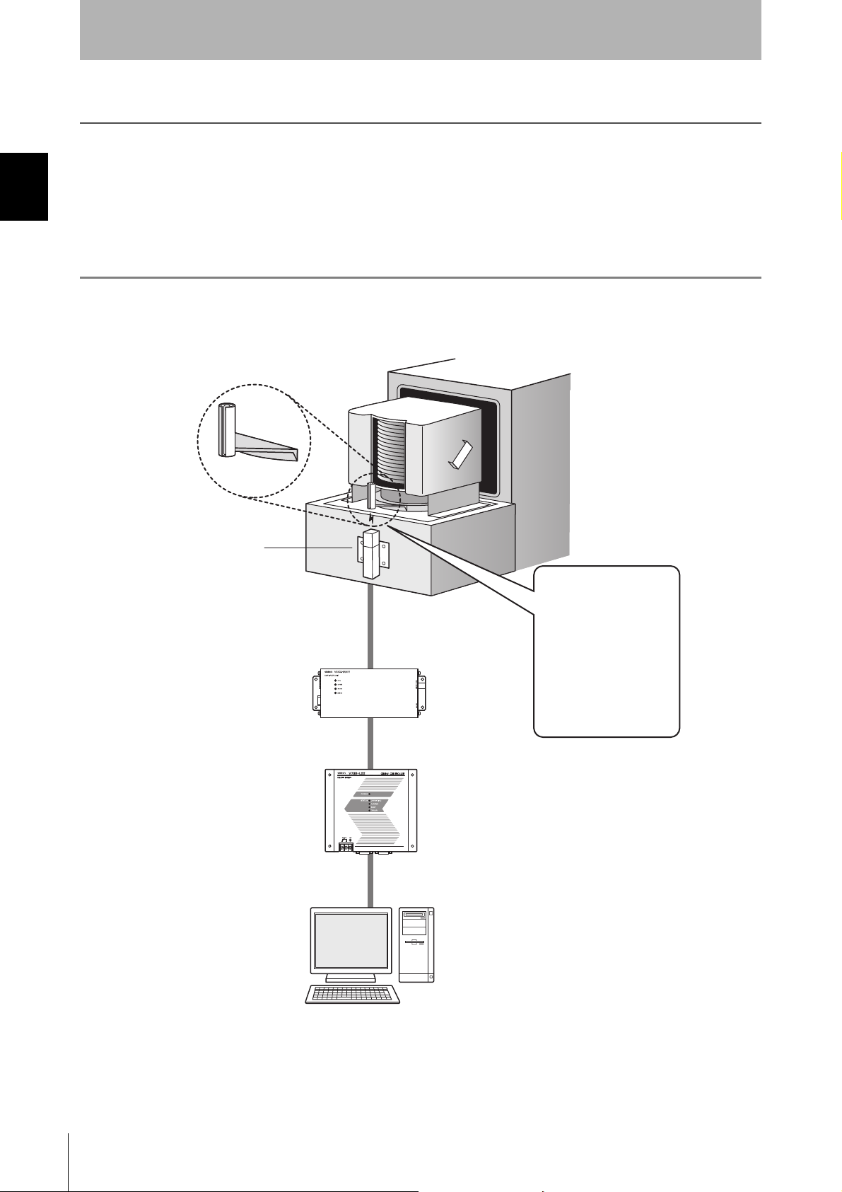
What is a CIDRW System?
SECTION 1
The CIDRW system writes data to, an d reads data from, the carrier IDs (ID Tags) mounted on the carriers
(FOUP) in semiconductor manufacturing processes without contacting these ID Tags. CIDRW is the
abbreviation of "Carrier ID Reader/Writer" and this abbreviation is used throughout this manual.
Reading and writing information such as models, process instructions, lots, and inspection results to and from
What is a CIDRW System?
ID Tags makes it possible to manage work instruction information from a host device.
Example: Management of information in semiconductor and wafer manufacturing processes
ID Tag
(holder is separate)
CIDRW Head
Amplifier Unit
CIDRW Controller
Host
Reading and writing
information
• Model information
• Process instruction
information
• Completion
information
• Lot information
• Inspection resu lts
Etc.
16
CIDRW System
User’s Manual
Features
SECTION 1
Product Outline
CIDRW Systems that Conform to SEMI Standards (SEMI E99, E5, E4)
CIDRW System Conforming to SEMI Standards
CIDRW Controller
Host
SECS I/II
RS-232C
List of Applicable Standards
• SEMI E99 THE CARRIER ID READER/WRITER FUNCTIONAL STANDARD
• SEMI E5 EQUIPMENT COMMUNICATION STANDARD 2 MESSAGE CONTENT (SECS II)
• SEMI E4 EQUIPMENT COMMUNICATION STANDARD 1 MESSAGE TRANSFER (SECS I)
SEMI is the acronym for Semiconductor Equipment and Materials International.
SECS is the acronym for SEMI Equipment Communications Standard.
V700-L22
RS-232C
Amplifier Unit
V640-HAM11
CIDRW Head
V640-HS61
ID Tag
RI-TRP-DR2B
(Made by Texas
Instruments)
SECTION 1
Features
CIDRW System
User’s Maual
17
SECTION 1
Product Outline
System Configuration
SECTION 1
System Configuration
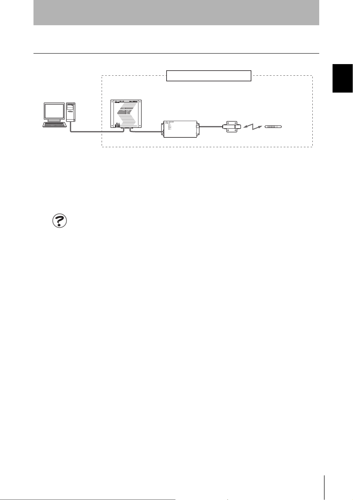
When SECS is Used
Communication with the host device is possible using the SECS protocol.
CIDRW Controller
Host
RS-232C
SECS I/II
This is e.g. a host,
or equipment controller.
V700-L22
RS-232C
Multiple Amplifier Units
are controlled in
response to commands
(SECS) from the host
device.
Amplifier Unit
V640-HAM11
These are units that
control a CIDRW Head.
CIDRW Head
V640-HS61
These are antennae for
reading the carrier IDs
from the ID Tags and
writing the carrier IDs.
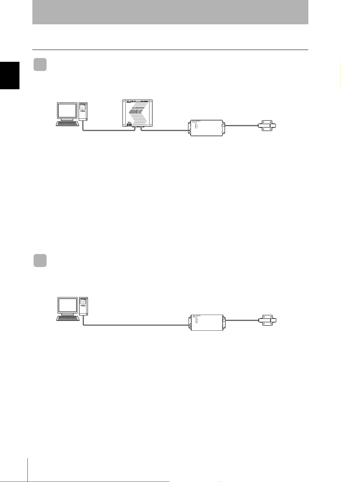
When SECS is Not Used
Communications with the host device follow the OMRON proprietary protocol.
The Amplifier Units are connected directly to the host device without using a CIDRW Controller.
Host
CIDRW Head
V640-HS61
These are antennae for
reading the carrier IDs
from the ID Tags and
writing the carrier IDs.
This is e.g. a host,
or equipment controller.
RS-232C
OMRON proprietary
Amplifier Unit
V640-HAM11
protocol
These are units that
control a CIDRW Head.
18
CIDRW System
User’s Manual
Component Names and Functions
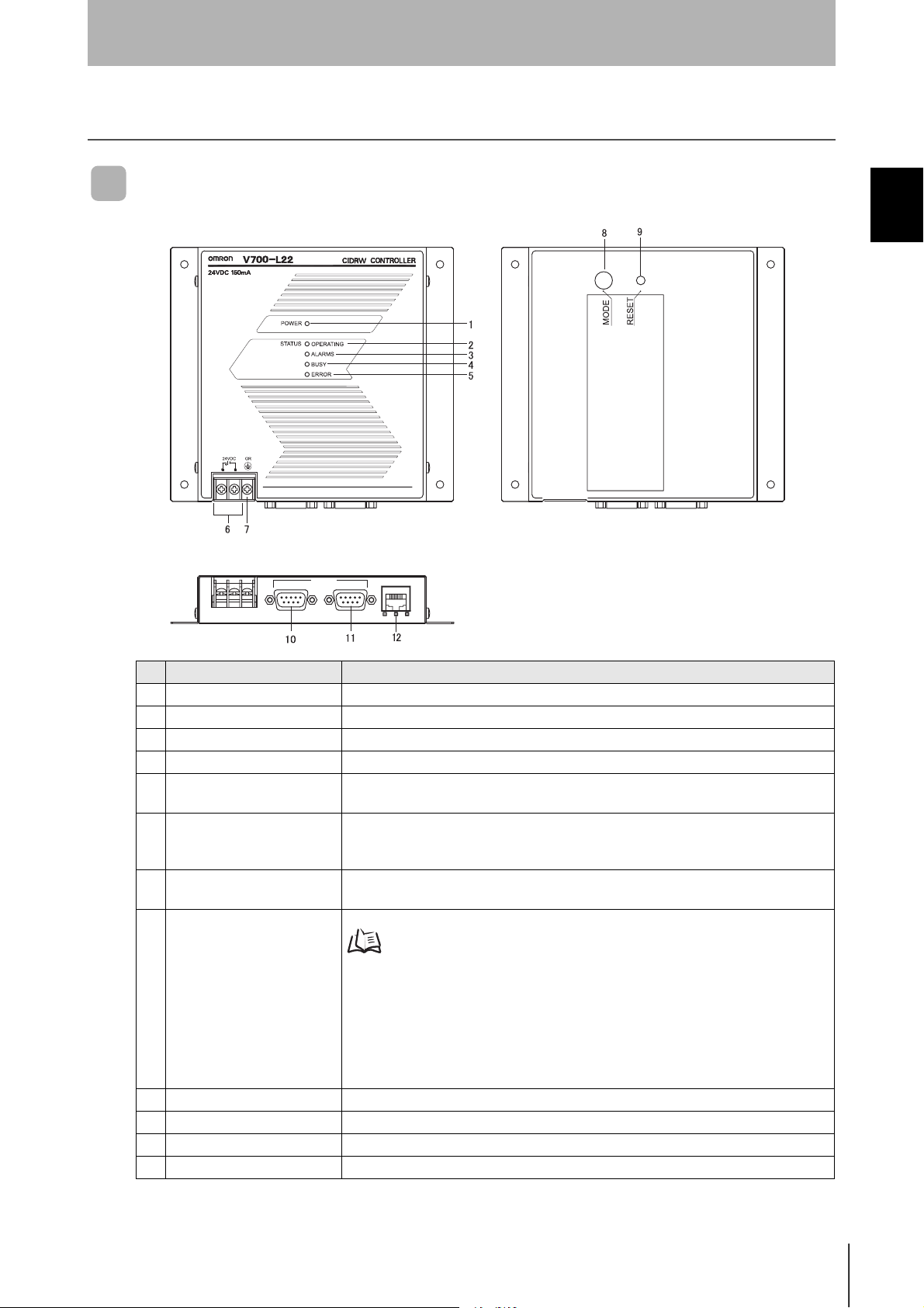
CIDRW Controller V700-L22
SECTION 1
Product Outline
SECTION 1
Component Names and Functions
45%
5'%5 +&
No. Name Function
1 Power indicator (green) An LED that indicates whether the power is ON or OFF . Lit while the power is ON.
2 OPERATING indicator (green) Lit while the CIDRW system status model is operating.
3 ALARMS indicator (green) Lit when the status of "AlamStatus" of the CIDRW system is "Alarm (1)."
4 BUSY indicator (green) Lit when the status of "OparationalStatus" of the CIDRW system is "BUSY."
5 ERROR indicator (red) When a processing error is detected (when SSACK is other than "NO"), this indicator is
6 24 VDC power supply termi-
nals
(with cover)
7 Frame ground terminal
(with cover)
8 MODE switch Used to select the mode of operation.
/#+06'0#00%'
lit for 50 ms.
Connect to the 24 VDC power supply.
The grounding wire is connected here. (Ground to 100 Ω or less)
Refer to page 48.
0 : Normal Operation mode. When mounting the Controller, set the switch to this posi-
tion.
3 : Setting mode, selected to set information such as the communication conditions.
When the switch on the bottom face of the Controller cannot be accessed, the operation mode can be changed from the host device while the switch is left at the "0" setting.
1 - 2, 4 - 7 :
9 RESET switch Restarts the CIDRW Controller.
10 SECS port Port for connecting the host device. Conforms to SECS I/II.
11 ID port An Amplifier Unit or Link Unit is connected here.
12 Maintenance port (with cover) Not used. Do not remove the cover.
Setting prohibited
CIDRW System
User’s Maual
19
SECTION 1
Product Outline
SECTION 1
Component Names and Functions
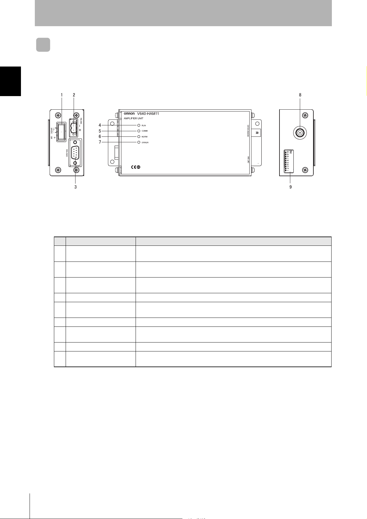
Amplifier Unit V640-HAM11
No. Name Function
1 Dedicated power supply con-
nector
2 RS-485 port When using multiple CIDRW Heads, connect this to the RS-485 port of another Amplifier
3 RS-232C port Connected to a CIDRW Controller or a host device.
4 RUN indicator (green) Turns ON when the Amplifier Unit is in normal operation.
5 COMM indicator (yellow) Turns ON during communications with the host device or during communications with an
6 NORM indicator (green) Turns ON when the communications finish with no error.
7 ERROR indicator (red) Turns ON when an error occurs during communication with the host device, or during
8 CIDRW Head connection port A CIDRW Head is connected here.
9 Setting DIP switches Used to set the node number, the communications conditions, and the RS-485 terminal
Connect to the 24 VDC power supply.
Unit or to the multi-connection port of a Link Unit.
Uses the OMRON proprietary communications protocol.
ID Tag.
communication with an ID Tag.
resistance.
20
CIDRW System
User’s Manual
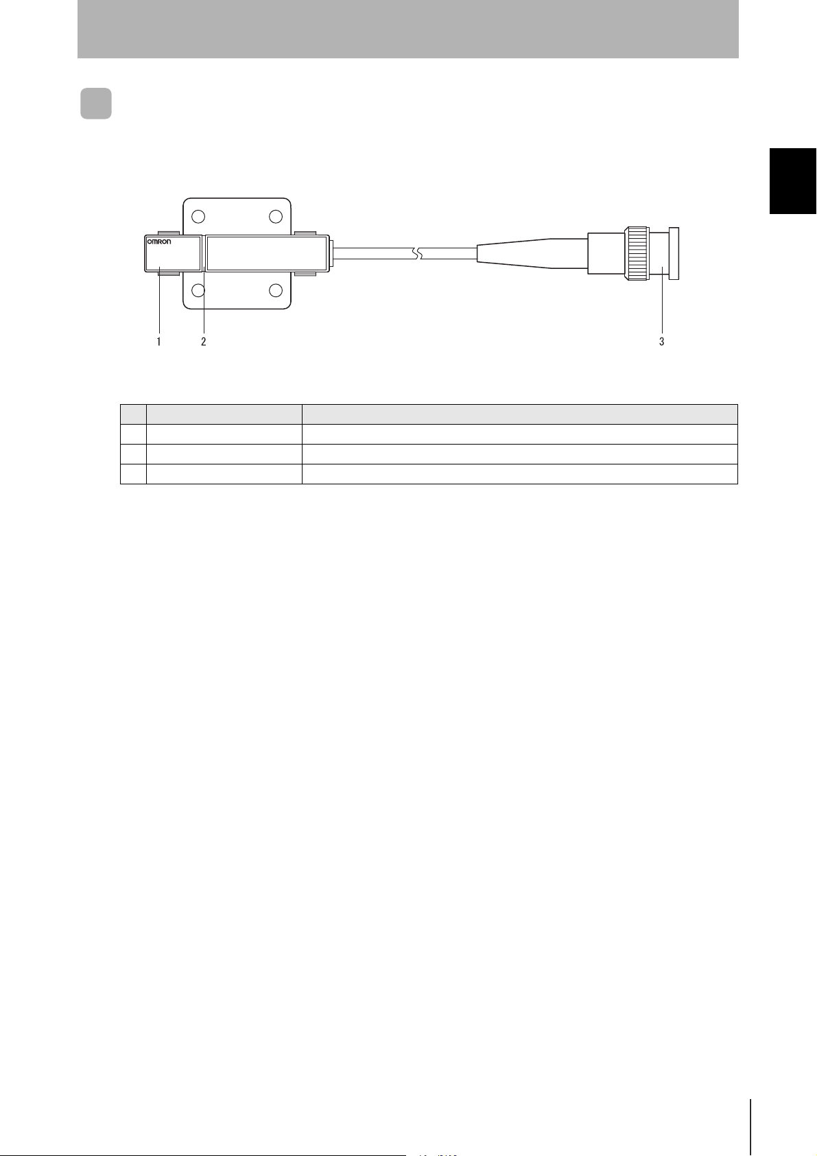
CIDRW Head V640-HS61
V640-HS61
CIDRW HEAD
No. Name Function
1 Antenna Used to communicate with ID Tags.
2 Antenna center This is the center of the communications area.
3 Connector Connect to an Amplifier Unit.
SECTION 1
Product Outline
SECTION 1
Component Names and Functions
CIDRW System
User’s Maual
21
SECTION 1
Product Outline
SECTION 1
Component Names and Functions
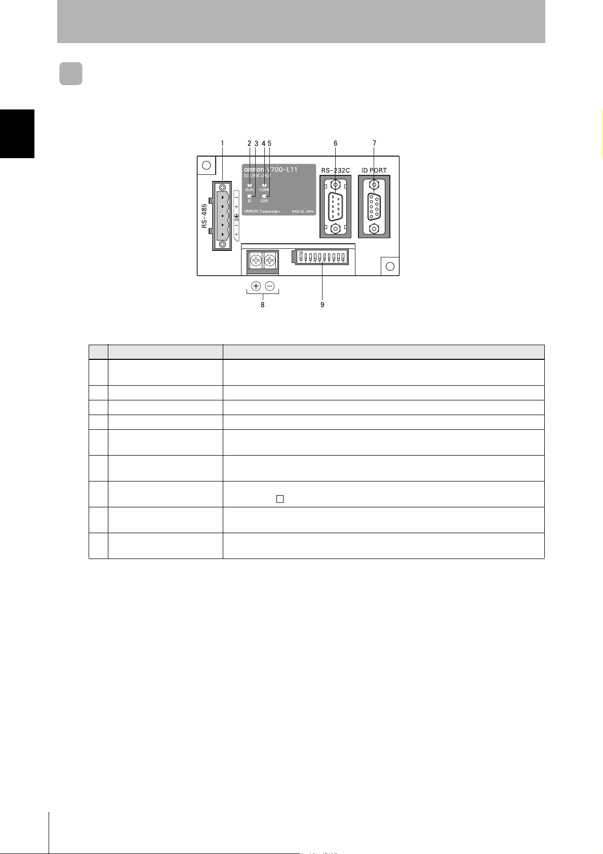
Link unit V700-L11
No. Name Function
1 Multi-connection port
(RS-485)
2 RUN indicator (green) Turns ON while the Link Unit is in normal operation.
3 ID indicator (green) Turns ON during data communications with a V700 series IDRW Head.
4 COMM indicator (green) Turns ON during data communications with the host device.
5 ERR indicator (red) Turns ON when an error occurs during data communications with the host device or
6 Host device connection port
(RS-232C)
7 ID connection port This is a dedicated port for connecting a V700 series IDRW Head. Connect either a
8 24 V power supply terminals
(inside the cover)
9 Setting DIP switches
(inside the cover)
This is the port that connects to the Amplifier Units when multiple CIDRW Heads are
connected to a CIDRW Controller. The GR (frame ground) terminal is also at this port.
head.
This is a port for connecting to the CIDRW Controller via an RS-232C interface. A dust
cover is fitted on shipment from the factory. Remove this cover before using the port.
V700-HMD13 or V700-HMD11-1 IDRW Head.
Connect to the 24 VDC power supply.
Used to set the equipment number, the communications conditions, and the RS-485 terminal resistance.
22
CIDRW System
User’s Manual
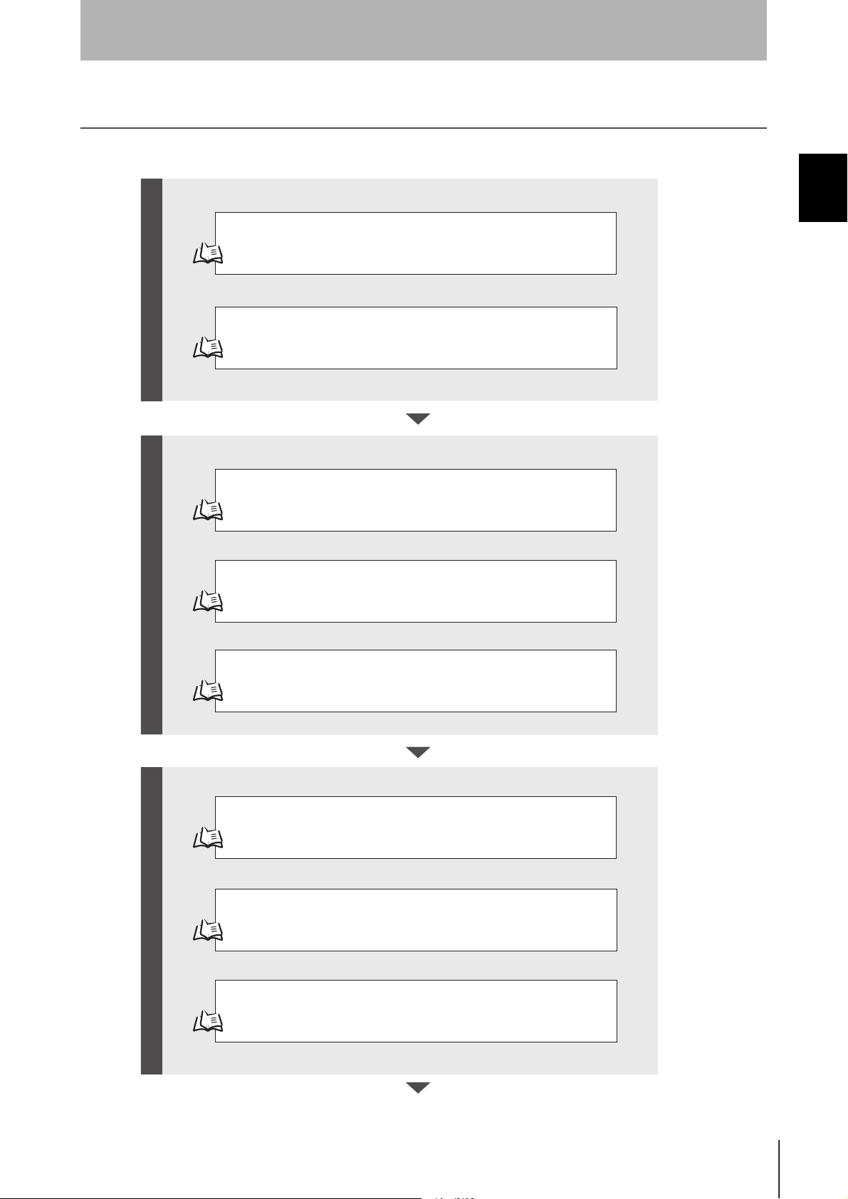
Flowchart for Getting Started
SECTION 1
Product Outline
SECTION 1
Installation
Refer to page 26.
Connection and Wiring
Refer to page 31.
Set the Communications Conditions for the CIDRW Controller
Refer to page 48.
Set the Communications Conditions for Amplifier Units
Refer to page 61.
Flowchart for Getting Started
Preparation for Communicatio nsTrial Operation Installation and Connections
Set the Communications Conditions for Link Units
Refer to page 63.
Test for Communications with the Host Device
Refer to page 65.
ID Tag <-> CIDRW System Communications Test
Refer to page 66.
Check the Surrounding Environment
Refer to page 28.
CIDRW System
User’s Maual
23
SECTION 1
Product Outline
SECTION 1
Flowchart for Getting Started
Communications
When SECS is Used
Refer to page 70.
When SECS is Not Used
Refer to page 81.
When you Encounter a Problem...
When SECS is Used
Refer to page 92. List of Error Messages
Refer to page 92. Controller Indicators
Refer to page 93. Operation Check Flowchart
When SECS is Not Used
Refer to page 98. List of Error Messages
Refer to page 98. Amplifier Unit Indicators
Refer to page 99. Operation Check Flowchart
24
CIDRW System
User’s Manual

SECTION 2
Installation and Connections/Wiring
Installation 26
Connections and Wiring 31
SECTION 2
Installation and Connections/Wiring
CIDRW System
User’s Maual
25

SECTION 2
SECTION 2
Installation and Connections/Wiring
Installation
CIDRW Controller
There is a switch for selecting the operation mode (Normal Operation mode <-> Setting mode) on the bottom face of the
CIDRW Controller. Set the communications conditions in the Setting mode (switch position 3) before mounting the
CIDRW Controller.
Refer to page 48.
Installation
Set the Controller to the Normal Operation mode (switch position 0) when mounting it.
Mount the CIDRW Controller with the resin washers and four M4 screws provided as accessories.
26
• Tighten the M4 screws with a torque not exceeding 1.2 N·m.
• Do not apply organic solvents used with screw locking agents at the locations where the screws are inserted.
CIDRW System
User’s Manual
Mounting dimensions
r
(Unit: mm)
/
r
SECTION 2
Installation and Connections/Wiring
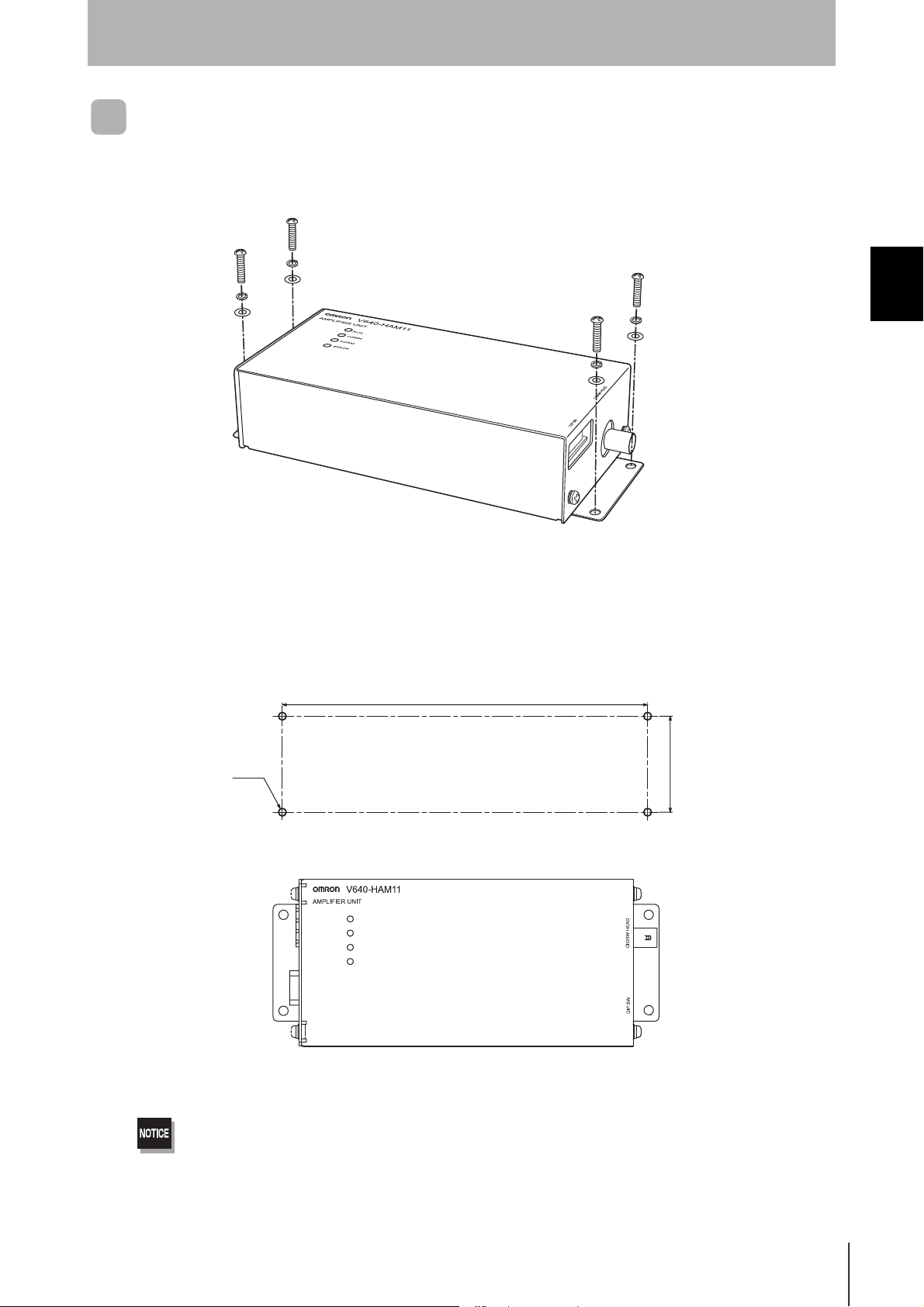
Amplifier Unit
Use spring washers and flat washers with the four M4 screws when mounting the Amplifier Unit.
SECTION 2
Installation
Mounting dimensions
/
(Unit: mm)
r
r
RUN
COMM
NORM
ERROR
Tighten the M4 screws with a torque not exceeding 1.2 N·m.
CIDRW System
User’s Manual
27
SECTION 2
Installation
SECTION 2
Installation and Connections/Wiring
CIDRW Head
The area for communications with ID Tags varies substantially according to the installation orientations
and the background con dition s (metals, no ise, etc .). Check the comm unicati ons ar ea before de cidin g
the installation position.
For details on actual com munications dis tances, see Characte ristic Data dependin g on Conditions of
Use in Appendix.
Refer to page 109.
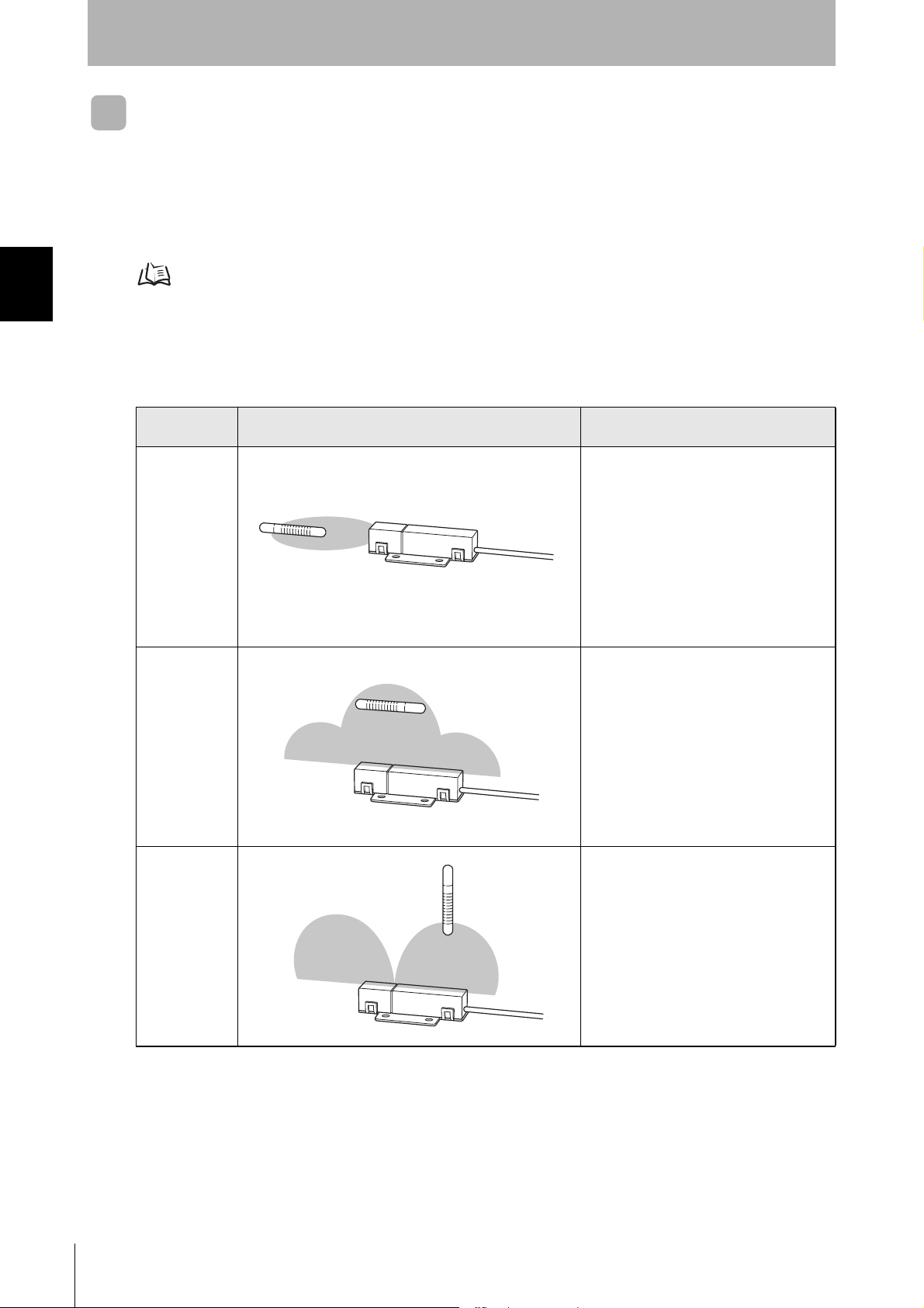
Positional Relationship between the CIDRW Head and the ID Tag
The communications area differs according to the positional relationship during communications.
Mounting
orientation
Coaxial The maximum communications area is
Parallel The maximum communications area is
Vertical When the center point of the antenna on the
Communications area (purely illustrative) Explanation
obtained when the centerlines of the CIDRW
Head and the ID Tag coincide.
obtained when the center point of the
antenna on the CIDRW Controller is aligned
with the centerline of the ID Tag.
CIDRW Head is aligned with the centerline of
the ID Tag, the communications area is substantially reduced.
28
Data Reading and Writing
The communicatio ns distances for reading and writ ing are not the same; the d istance is shorter for
writing. Therefore, when data is to be both r ead and writt en, take the distance for writing as the reference distance when installing the CIDRW Head and the ID Tag.
CIDRW System
User’s Manual
Installation and Connections/Wiring
Influence of Background Metal on ID Tag
Metals in the vicinity of the communications area will affect the range, making it smaller.
Refer to page 115.
SECTION 2
Influence of Noise
This CIDRW system uses a freque ncy of 134 kH z for communi cations wi th ID Tags. Equipment such
as switching power supplies, inverters, servomotors, or monitors in the surrounding area will adversely
affect communications, restricting the communications area.
The noise levels in the vicinity of the CIDRW Head can be determined with the environmental noise measurement command (applies only when SECS is not used). Refer to page 89.
For details on the relationship between noise and communications distance, see Appendix. Refer to page 121.
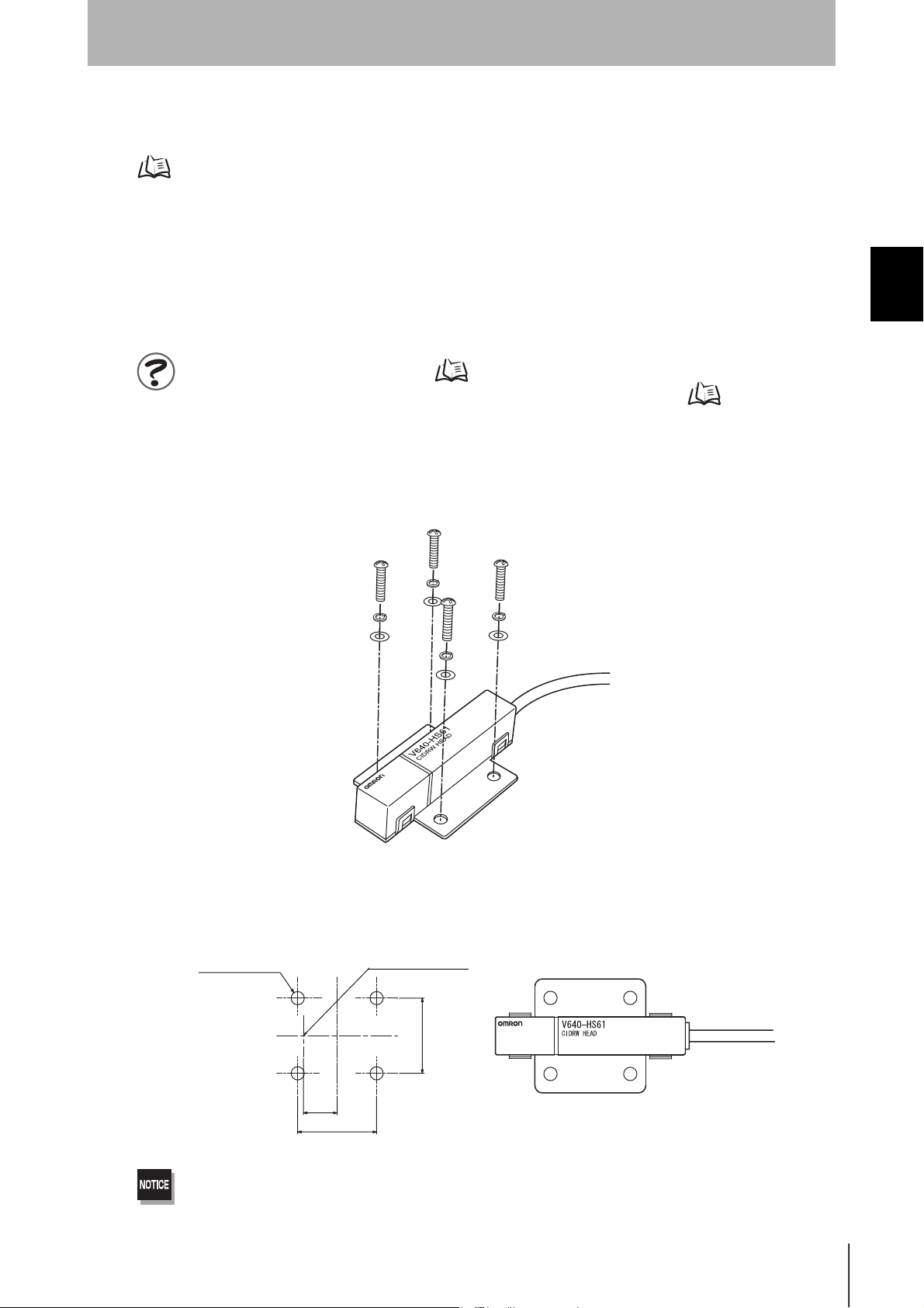
Mounting
Use spring washers and flat washers with the four M3 screws when mounting a CIDRW Head.
SECTION 2
Installation
Mounting dimensions
(Unit: mm)
/14Ǿ
r
Tighten the M3 screws with a torque not exceeding 0.6 N·m.
Be sure to install the Amplifier Unit in a panel or metal-shielded equipment.
Antenna center
r
CIDRW System
User’s Manual
29
SECTION 2
Installation
SECTION 2
Installation and Connections/Wiring
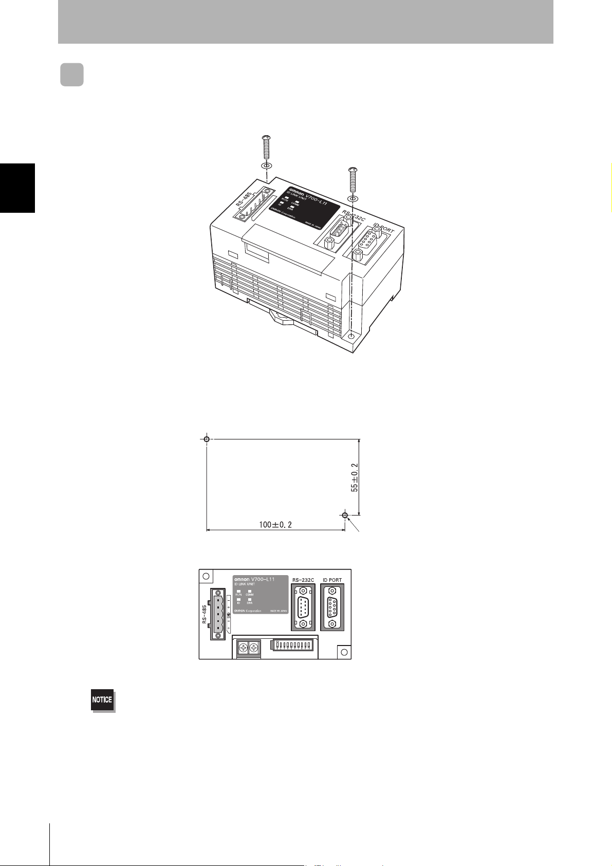
Link Unit
Mount Link Units with the two M4 screws and washers provided as accessories.
Mounting dimensions
(Unit: mm)
Two M4 or 4.2-dia. holes
• Tighten the M4 screws with a torque not exceeding 1.2 N·m.
• Do not apply organic solvents used with screw locking agents at the locations where the screws are inserted.
30
CIDRW System
User’s Manual

Connections and Wiring
CIDRW Controller
Power Supply and Grounding Wires
Connect the wires to the 24 VDC power supply terminals and frame ground terminal.
SECTION 2
Installation and Connections/Wiring
SECTION 2
Connections and Wiring
24 VDC
Ground to 100 Ω or less.
• Crimp terminals
The terminal screws on the terminal block are M3 size. Use appropriate crimp terminals for M3 screws
as shown below.
Crimp terminals
Shape Size
Forked
6 mm max.
Round
6 mm max.
• Power supply
Use a power supply unit that satisfies the following conditions.
Condition
Power supply voltage Output current
24 VDC +10%, -15% 500 mA DC min.
Recommended model
Manufacturer Model
OMRON S82K-01524
Be sure to replace the cover after wiring.
CIDRW System
User’s Manual
31
 Loading...