

Omron 3G3RX-V1 Connection Manual

CJ-series
DeviceNet™ Connection Guide
OMRON Corporation
3G3RX-V1 Series Inverter
P547-E1-01

About Intellectual Property Rights and Trademarks
Microsoft product screen shots reprinted with permission from Microsoft Corporation.
Windows is a registered trademark of Microsoft Corporation in the USA and other countries.
ODVA and DeviceNet™ are trademarks of ODVA.
Company names and product names in this document are the trademarks or registered
trademarks of their respective companies.

Table Of Contents
1. Related Manuals........................................................................................ 1
2. Terms and Definitions............................................................................... 1
3. Remarks..................................................................................................... 2
4. Overview .................................................................................................... 4
5. Applicable Products and Support Software............................................4
5.1. Applicable Products............................................................................... 4
5.2. Device Configuration............................................................................. 5
6. Connection Procedure.............................................................................. 7
6.1. Unit Setting Example............................................................................. 7
6.2. Work Flow.............................................................................................. 9
6.3. Setting Up the Inverter......................................................................... 10
6.4. Setting Up the DeviceNet .................................................................... 17
6.5. Connection Status Check.................................................................... 33
7. Initialization Method................................................................................ 40
7.1. PLC ..................................................................................................... 40
7.2. Inverter ................................................................................................ 41
8. Revision History...................................................................................... 42

1.Related Manuals
1
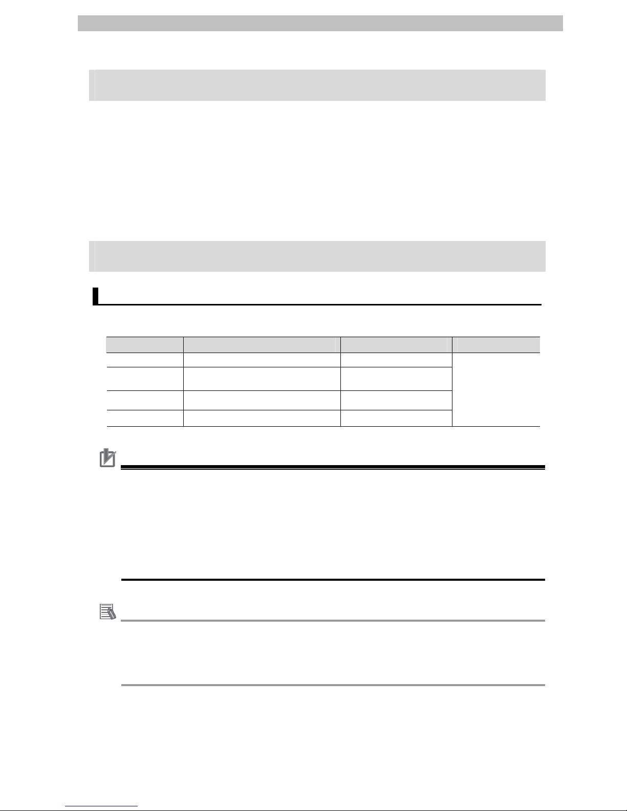
1. Related Manuals
The table below lists the manuals that relate to this document.
To ensure system safety, make sure to always read and heed the information provided in all
Safety Precautions, Precautions for Safe Use, and Precaution for Correct Use of manuals for
each device which is used in the system.
Cat.No. Model Manual Name
W472 CJ2H-CPU6[]
CJ2M-CPU[][]
CJ-series CJ2 CPU Unit Hardware User's Manual
W473 CJ2H-CPU6[]
CJ2M-CPU[][]
CJ-series CJ2 CPU Unit Software User's Manual
W267 - DeviceNet™ Operation Manual
W380 CJ1W-DRM21 CJ-series DeviceNet™ Unit Operation Manual
W446 - SYSMAC CX-Programmer Operation Manual
W464 - SYSMAC CX-Integrator Operation Manual
I578 3G3RX-[][][][][]-V1 RX Series Type V1 High-function General-purpose
Inverter User's Manual
I581 3G3AX-RX-DRT-E MX2/RX Series DeviceNet Communications Unit
User's Manual
2. Terms and Definitions
Term Explanation and Definition
Master/Slave A master is a unit that controls the DeviceNet communications.
A master sends output data to multiple slaves and receives input data
from the slaves.
Slaves receive output data that are sent from the master, and send input
data to the master.
At least one master is required for DeviceNet communications.
EDS file An EDS file is a file that contains the I/O points of DeviceNet slave units
and the parameters that can be set via DeviceNet.
Node address
(MAC ID)
A node address is an address to identify a unit connected to a DeviceNet
network.
With DeviceNet, a MAC (Media Access Control) ID is used as a node
address. Thus, a node address is a MAC ID.
Scan list A scan list is used to register slaves with which a master communicates
in DeviceNet remote I/O communications. A master communicates with
the slaves based on the scan list settings.

3.Remarks
2
3. Remarks
(1) Understand the specifications of devices which are used in the system. Allow some
margin for ratings and performance. Provide safety measures, such as installing safety
circuit in order to ensure safety and minimize risks of abnormal occurrence.
(2) To ensure system safety, always read and heed the information provided in all Safety
Precautions, Precautions for Safe Use, and Precaution for Correct Use of manuals for
each device used in the system.
(3) The user is encouraged to confirm the standards and regulations that the system must
conform to.
(4) It is prohibited to copy, to reproduce, and to distribute a part of or whole part of this
document without the permission of OMRON Corporation.
(5) The information contained in this document is current as of January 2013. It is subject to
change without notice for improvement.
3.Remarks
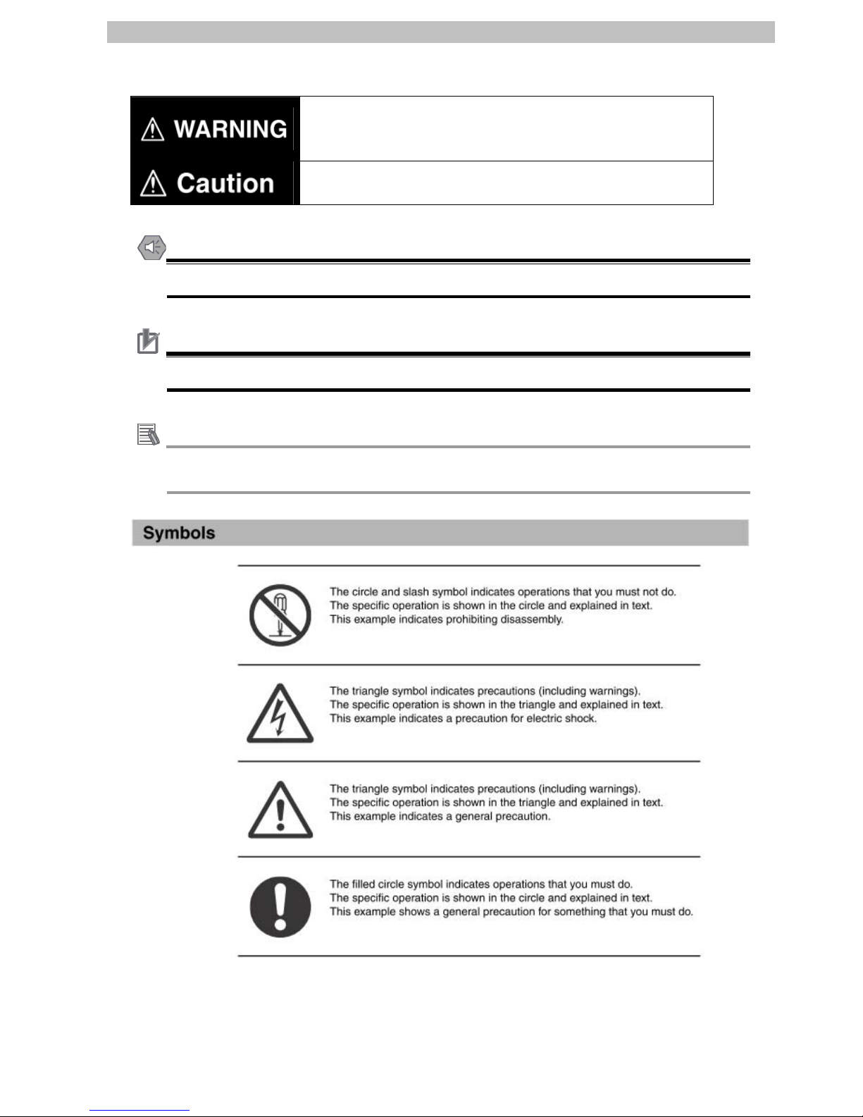
The following
notation is used in this document.
Indicates a potentially hazardous situation which, if not avoided,
will result in minor or moderate injury, or may result in serious
injury or death. Additionally there may be significant property
damage.
Indicates a potentially hazardous situation which, if not avoided,
may result in minor or moderate injury or in property damage.
Precautions for Safe Use
Precautions on what to do and what not to do to ensure safe usage of the product.
Application precautions
Precautions on what to do and what not to do to ensure proper operation and performance.
Additional Information
Additional information to read as required.
This information is provided to increase understanding or make operation easier
3
4.Overview
4. Overview
This document describes the procedure for connecting the Inverter (3G3RX-V1 series) of
OMRON Corporation (hereinafter referred to as OMRON) to the DeviceNet Unit and provides
the procedure for checking their connection.
Refer to Section 6 Connection Procedure to understand the setting method and key points to
connect the devices via DeviceNet.
5. Applicable Products and Support Software
5.1. Applicable Products
The applicable devices are as follows:
Manufacturer Name Model Version
OMRON DeviceNet Unit (Master) CJ1W-DRM21
OMRON
CJ1-series CPU Unit
CJ2-series CPU Unit
CJ1[]-CPU[][]
CJ2[]-CPU[][]
OMRON
Inverter 3G3RX –[][][][][]-V1
OMRON
DeviceNet Communications Unit 3G3AX-RX-DRT-E
Versions listed in
Section 5.2 or
higher versions
Precautions for Correct Use
As applicable devices above, the devices with the models and versions listed in Section 5.2.
are actually used in this document to describe the procedure for connecting devices and
checking the connection.
You cannot use devices with versions lower than the versions listed in Section 5.2.
To use the above devices with versions not listed in Section 5.2 or versions higher than those
listed in Section 5.2, check the differences in the specifications by referring to the manuals
before operating the devices.
Additional Information
This document describes the procedure to establish the network connection. Except for the
connection procedure, it does not provide information on operation, installation or wiring
method. It also does not describe the functionality or operation of the devices. Refer to the
manuals or contact your OMRON representative.
4
5.Applicable Products and Support Software
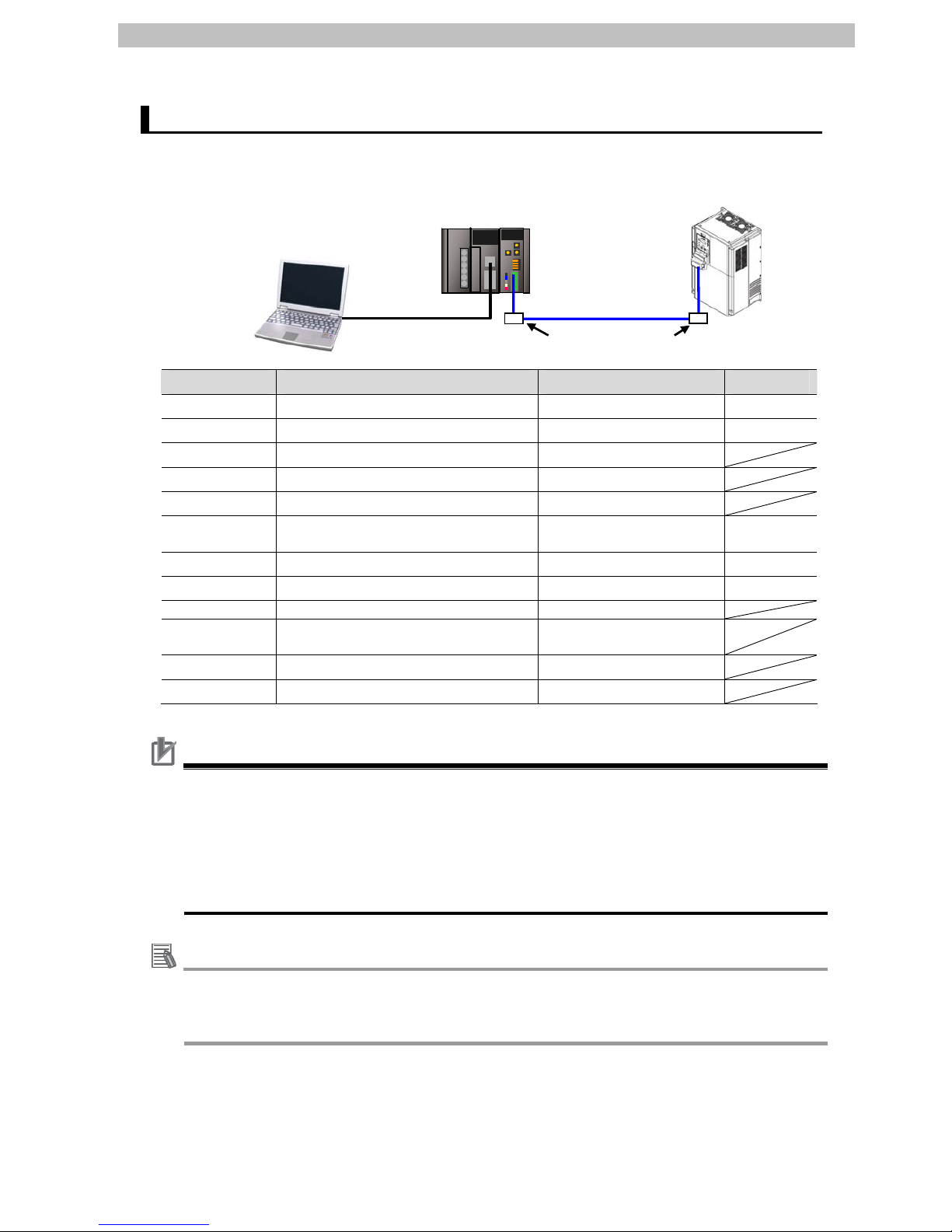
5.2. Device Configuration
The hardware components to reproduce the connection procedure of this document are as
follows:
USB cable
Personal computer
(CX-One in
stalled,
OS: Windows XP)
CJ2M-CPU12 +
CJ1W-DRM21
DeviceNet cable
3G
3RX-A2055-V1 +
3G3AX-RX-DRT-E
T-branch Tap (DCN1-1C)
Manufacturer Name Model Version
OMRON
DeviceNet Unit (Master) CJ1W-DRM21 Ver.1.1
OMRON
CJ2 CPU Unit CJ2M-CPU12 Ver.2.0
OMRON
Power Supply Unit CJ1W-PA202
OMRON
DeviceNet cable DCA1-5C10
OMRON
T-branch Tap DCN1-1C
OMRON
CX-One CXONE-AL[][]C-V4
/AL[][]D-V4
Ver.4.[][]
OMRON
CX-Programmer (Included in CX-One) Ver.9.41
OMRON
CX-Integrator (Included in CX-One) Ver.2.55
- USB cable -
- Personal computer
(OS: Windows XP)
-
OMRON
Inverter 3G3RX -A2055-V1
OMRON
DeviceNet Communications Unit 3G3AX-RX-DRT-E
Precautions for Correct Use
Update the CX-Programmer and CX-Integrator to the version specified in this section or
higher version using the auto update function. If a version not specified in this section is used,
the procedures described in Section 6 and subsequent sections may not be applicable. In
that case, use the equivalent procedures described in the SYSMAC CX-Programmer
Operation Manual (Cat.No. W446) and SYSMAC CX-Integrator Operation Manual (Cat. No.
W464).
Additional Information
For information on the DeviceNet cable and network wiring, refer to Chapter 2 Network
Configuration and Wiring of the DeviceNet Operation Manual (Cat. No. W267).
Connect a terminating resistance to each end of the trunk line of the DeviceNet.
5

5.Applicable Products and Support Software
Additional Information
The system configuration in this document uses USB for the connection between the
personal computer and CJ2.
For information on how to install the USB driver, refer to A-5 Installing the USB Driver in the
CJ2 CPU Unit Hardware User's Manual (Cat. No. W472).
6

6.Connection Procedure
7
6. Connection Procedure
6.1. Unit Setting Example
This section explains the procedure for connecting the DeviceNet Unit.
This document explains the procedures for setting up the DeviceNet Unit and Inverter from the
factory default setting. For information on how to initialize each device, refer to Section 7
Initialization Method.
6.1.1. Settings
The settings for the DeviceNet Unit and Inverter are shown below.
DeviceNet Unit Inverter
Unit number 0 Node address (MAC ID) 63 0
Baud rate (bps) 500kbps (Automatically follows the Master Unit)
Remote I/O - 1 (Extended Speed I/O)
6.1.2. I/O Memory Area Allocation
The memory area of the PLC is allocated to the Inverter as shown below.
Output area 4 bytes
(PLC → Inverter)
Input area 4 bytes
(Inverter → PLC)
3200 Command 3300 Status information
3201 Rotation Speed
Reference
3301 Rotation Speed Monitor
■Output format
Bit allocation
Word
15 14 13 12 11 10 9 8 7 6 5 4 3 2 1 0
3200 - - - - - - - - - REFCTR - - RS RV FW
3201 Rotation Speed Reference

6.Connection Procedure
8
■Deta
ils on output area
Name Meaning
FW Forward/stop 0: Stop, 1: Forward
RV Reverse/Stop 0: Stop, 1: Reverse
RS Fault reset 0:-, 1: Fault reset
CTR Net Ctrl.
0: Follow the setting of parameter A002.
1: Follow the reference from network control.
REF Net Ref.
0: Follow the setting of parameter A001.
1: Follow the reference from network control.
Rotation Speed Reference
If parameter P049 (Number of Poles for Rotation Speed
Setting) is set appropriately , the rot a tional speed unit is [min -1].
If parameter P049 (Number of Poles for Rotation Speed
Setting) is set to 0, the frequency unit is [0.01 Hz].
■Input format
Bit allocation
Word
15 14 13 12 11 10 9 8 7 6 5 4 3 2 1 0
3300 Drive status FA1RFNCFN
IRDY
RVR
FWR
WR AL
3301 Rotation Speed Monitor
■Details on input area
Name Meaning
AL Alarm output 0: Normal, 1: Fault/Trip
WR Warning 0: Normal, 1: Warning
FWR
During forward
operation
0: During reverse run/Stopping, 1: During forward run
RVR
During reverse
operation
0: During forward run/Stopping, 1: During reverse run
IRDY Operation ready 0: Not ready, 1: Ready
CFN Ctrl. From Net
0: Follow the setting of parameter A002.
1: DeviceNet reference
RFN Ref. From Net
0: Follow the setting of parameter A001.
1: DeviceNet reference
FA1
Constant speed
reached
0: Accelerating or decelerating/Stopping, 1: Frequency agree
Bit [15] to [11] [10] [9] [8]
1: Startup 0 0 0 1
2: Not ready 0 0 1 0
3: Ready 0 0 1 1
4: Operation in progress 0 1 0 0
5: Stopping 0 1 0 1
6: Fault/Trip stop 0 1 1 0
Drive Status
7: Fault/Trip 0 1 1 1
Rotation Speed Monitor
If parameter P049 (Number of Poles for Rotation Speed
Setting) is set appropriately , the rot a tional speed unit is [min -1].
If parameter P049 (Number of Poles for Rotation Speed
Setting) is set to 0, the frequency is monitored in units of [0.01
Hz].

6.Connection Procedure
9
6.2. Work Flow
Take the following steps to connect the DeviceNet Unit.
6.3. Setting Up the Inverter
Set up the Inverter.
↓
6.3.1. Hardware Setting Mount the DeviceNet Communications Unit on the
Inverter.
↓
6.3.2. Parameter Setting Set the parameters for the Inverter.
↓
6.4. Setting Up the DeviceNet Unit
Set up the DeviceNet Unit.
↓
6.4.1. Hardware Setting Set the hardware switches on the DeviceNet Unit.
↓
6.4.2. Starting the CX-Programmer
and Connecting online with
the PLC
Start the CX-Programmer and connect online with the
PLC.
↓
6.4.3. Creating I/O Table Create the I/O table for the CPU Unit.
↓
6.4.4. Starting CX-Integrator and
Setting the Network
Start the CX-Integrator and set the network and
device offline.
↓
6.4.5. Setting the Device Set the device and register it in the DeviceNet Unit
(create a scan list).
↓
6.4.6. Connecting Online and
Transferring a Scan List
Connect online with the PLC and transfer the
settings.
↓
6.5. Connection Status Check
Check the connection status of the DeviceNet
network.
↓
6.5.1. Checking the Connection
Status
Confirm that the DeviceNet communications is
normally performed.
↓
6.5.2. Checking Data that are Sent
and Received
Confirm that the correct data are sent and received.
6.Connection Procedure
6.3. Setting Up the Inverter
Set up the Inverter.
6.3.1. Hardware Setting
Mount the DeviceNet Communications Unit on the Inverter.
Precautions for Correct Use
Make sure that the power supply is OFF when you perform the setting up.
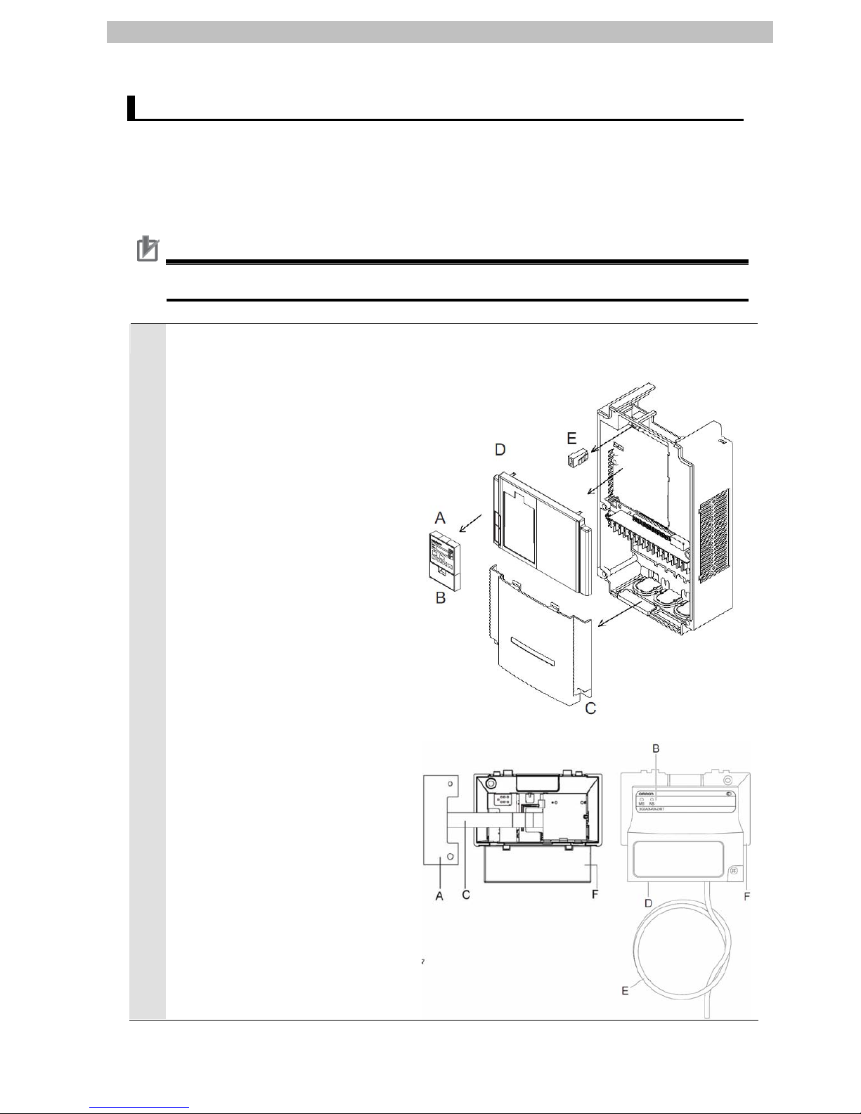
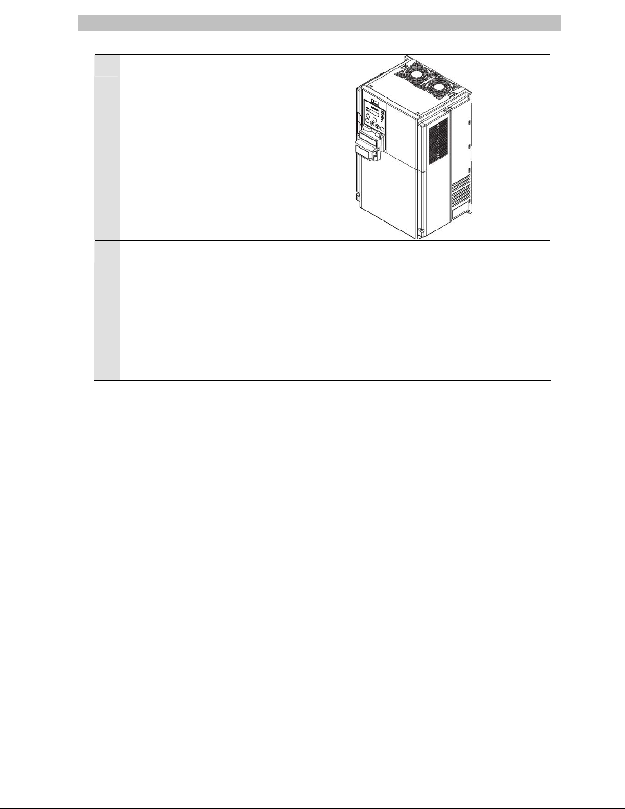
1
Check the name of each part on
the Inverter and the DeviceNet
Communications Unit by
referring to the right figure.
●Inverter
●DeviceNet Communications Unit
A. Inverter connection PCB
B. LED indicators (MS and NS)
C. Flat
cable
D. DeviceNet connector
E. Grounding cable
F. Housing
A. Digital Operator
B. Spacer cover
C. Terminal cover
D. Front cover
E. Operator connector
10
6.Connection Procedure
2
Mount the DeviceNet
Communications Unit on the
Inverter.
*For the mounting procedure of
the DeviceNet Communications
Unit, refer to 2-2-2 Mounting
Procedure of DeviceNet
Communications Unit on
RX-series Inverter in the
MX2/RX Series DeviceNet
Communication Unit User's
Manual (Cat. No. I581).
3
Connect the power supply to the
main power supply input
terminal.
*The location of the power
supply input terminal differs
depending on the model.
Refer to 2-3-4 Wiring for Main
Circuit Terminals in the RX
Series T ype V1 High-function
General-purpose Inverter
User's Manual (Cat. No. I578).
11
 Loading...