

Omron 3G3RX-A2015-V1, 3G3RX-A2022-V1, 3G3RX-A2037-V1, 3G3RX-A2055-V1, 3G3RX-A2075-V1 User Manual
...Page 1
High-function General-purpose Inverter
RX Series Type V1
User’s Manual
I578-E1-01
3G3RX--V1
Page 2

OMRON, 2012
All rights reserved. No part of this publication may be reproduced, stored in a retrieval system, or transmitted, in any
form, or by any means, mechanical, electronic, photocopying, recording, or otherwise, without the prior written
permission of OMRON.
No patent liability is assumed with respect to the use of the information contained herein. Moreover, because OMRON
is constantly striving to improve its high-quality products, the information contained in this manual is subject to change
without notice. Every precaution has been taken in the preparation of this manual. Nevertheless, OMRON assumes no
responsibility for errors or omissions. Neither is any liability assumed for damages resulting from the use of the
information contained in this publication.
Page 3

1
Introduction
High-function General-purpose Inverter 3G3RX-V1 User’s Manual (I578-E1)
Introduction
Thank you for purchasing the High-function General-purpose Inverter (Model: 3G3RX--V1).
This manual describes the installation and wiring methods of the 3G3RX-V1 Series Inverter, and
parameter setting methods which are required for the operation, as well as troubleshooting and
inspection methods.
This manual is intended for the following individuals.
Those who have electrical knowledge (certified electricians or individuals who have equivalent
knowledge) and also are qualified for one of the following:
• Introducing control equipment
• Designing control system
• Installing and connecting control systems
• Managing control systems and facilities
This manual contains information you need to know to correctly use the High-functi on General- purpose
Inverter (Model: 3G3RX--V1).
Before using the inverter, read this manual and gain a full understanding of the information provided
herein.
After you finished reading this manual, keep it in a convenient place so that it can be referenced at any
time.
Make sure this manual is delivered to the end user.
Intended Readers
Notice
Page 4

Manual Configuration
2
High-function General-purpose Inverter 3G3RX-V1 User’s Manual (I578-E1)
Manual Configuration
This manual is compiled section by section for user’s convenience as follows.
Section/Title Outline
Section 1 Overview
This section provides the features of this product,
specifications, external dimensions, and part names.
Section 2 Design
This section describes the installation and wiring
methods for this product.
Section 3 Operation and Test Run
This section describes the part names and key
operation of the Digital Operator, and the operation
method of this product as well as the test run
procedure.
Section 4 Parameter List
This section provides lists of parameters for setting
various functions of this product.
Section 5 Basic Settings
This section describes the basic functions, such as the
Run command.
Section 6 V ector Control
This section describes the applied functions, such as
vector control.
Section 7 Detailed Functions
This section describes the details of functions not
described in Section 5 or Section 6.
Section 8 Communications Func ti on s
This section describes the general-purpose serial
communications functions (RS-485 communication).
Section 9 Overview of DriveProgramming
This section describes the features of the
DriveProgramming.
Section 10 Troub le s h o oting
This section describes how to analyze the cause and
take countermeasures if the inverter fails, and provides
troubleshooting for possible troubles.
Section 11 Maintenance and Inspection
This section describes the maintenance and periodical
inspection items.
Section 12 Options
This section describes the specifications and external
dimension of peripheral equipment.
Appendices
This section provides information on the capacitor life
curve and the life alarm output.
Page 5
3
Manual Structure
High-function General-purpose Inverter 3G3RX-V1 User’s Manual (I578-E1)
Manual Structure
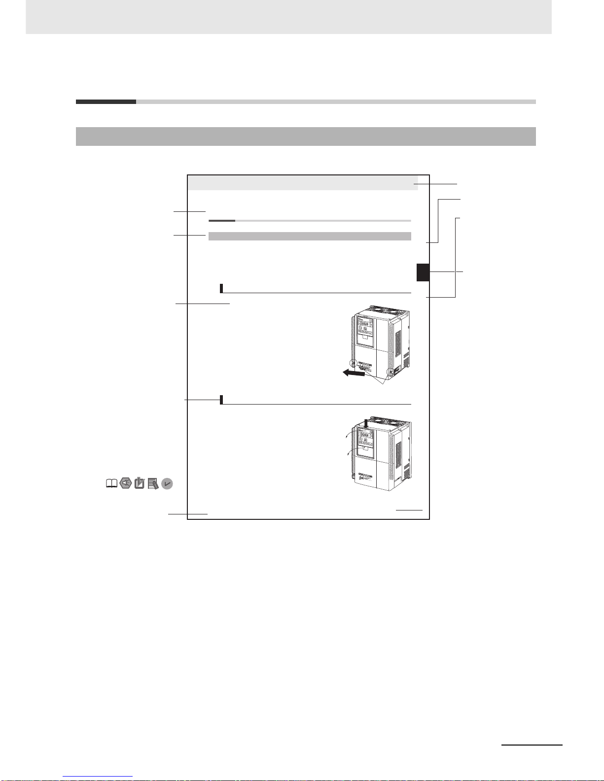
The following page structure and symbol icons are used in this manual.
Note The above page is only a sample for illustrative purposes. It is not the actual content of the manual.
Page Structure and Symbol Icons
2 - 9
2 Design
High-function General-purpose Inverter 3G3RX-V1 User’s Manual (I578-E1)
2-2 Removal of Each Part
2
2-2-1 Removing Covers
2-2 Removal of Each Part
Before wiring each terminal block, you need to remove the terminal block cover and the backing plate.
In addition, to install a PG Board or communications unit, you must remove the Digital Operator, spacer
cover, terminal block cover, and front cover beforehand.
This section describes how to remove these covers.
To r ein stall it, reverse the removal procedure.
1
Loosen the terminal block cover fixation screws.
There are two terminal block cover fixation screws,
one for each side of the cover.
Larger capacity Inverter models have three terminal
block cover fixation screws.
2
Remove the terminal block cover in the direction of
(a) while holding it from the bottom.
1
Remove the Digital Operator in the direction of (a) by
pushing the lip on the top.
2
In the same way, re move t he spacer cover in the
direction of (b).
2-2-1 Removing Covers
Removing Terminal Block Cover
Removing Digital Operator and Spacer Cover
(a)
Terminal block cover fixation screws
(a)
(b)
Level 1 heading
Level 2 heading
Level 3 heading
Level 2 heading
Operation Steps
Manual Name
Level 3 heading
Shows which
paragraph the
content of the current
page belongs to.
Describes the operation
steps.
Note, Supplementary
Information,
Reference Target
A note, supplementary
information, reference
target, etc. are
provided with
difference icons.
Shows which
section the content
of the current page
belongs to.
Section Number
of Level 1
heading
Page 6

Manual Structure
4
High-function General-purpose Inverter 3G3RX-V1 User’s Manual (I578-E1)
Special information in this manual is classified as follows:
Precautions for Safe Use
Precautions on what to do and what not to do to ensure safe usage of the product.
Precautions for Correct UsePrecautions for Correct Use
Precautions on what to do and what not to do to ensure proper operation and performance.
Additional Information
Additional information to read as required.
This information is provided to increase understanding or make operation easier.
Special Information
Page 7

5
Sections in this Manual
High-function General-purpose Inverter 3G3RX-V1 User’s Manual (I578-E1)
1
10
2
11
3
12
4A
5
6
7
8
9
1
10
2
11
3
12
4A
5I
6
7
8
9
Overview Troubleshooting
Design
Maintenance and
Inspection
Operation and Test Run
Options
Parameter List Appendices
I
IndexBasic Settings
Vector Control
Detailed Functions
Communications Functions
Overview of DriveProgramming
Sections in this Manual
Page 8

Read and Understand this Manual
6
High-function General-purpose Inverter 3G3RX-V1 User’s Manual (I578-E1)
Read and Understand this Manual
Warranty and Limitations of Liability
WARRANTY
OMRON’s exclusive warranty is that the products are free from defects in materials and workmanship for a period of
one year (or other period if specified) from date of sale by OMRON.
OMRON MAKES NO WARRANTY OR REPRESENTATION, EXPRESS OR IMPLIED, REGARDING
NONINFRINGEMENT, MERCHANTABILITY, OR FITNESS FOR PA RTICULAR PURPOSE OF THE PRODUCTS.
ANY BUYER OR USER ACKNOWLEDGES THAT THE BUYER OR USER ALONE HAS DETERMINED THAT THE
PRODUCTS WILL SUITABL Y MEET THE REQUIREMENTS OF THEIR INTENDED USE. OMRON DISCLAIMS ALL
OTHER WARRANTIES, EXPRESS OR IMPLIED.
LIMITATIONS OF LIABILITY
OMRON SHALL NOT BE RESPONSIBLE FOR SPECIAL, INDIRECT, OR CONSEQUENTIAL DAM AGES , LOSS OF
PROFITS OR COMMERCIAL LOSS IN ANY WAY CONNECTED WITH THE PRODUCTS, WHETHER SUCH
CLAIM IS BASED ON CONTRACT, WARRANTY, NEGLIGENCE, OR STRICT LIABILITY.
In no event shall the responsibility of OMRON for any act exceed the individual price of the product on which liability
is asserted.
IN NO EVENT SHALL OMRON BE RESPONSIBLE FOR WARRANTY, REPAIR, OR OTHER CLAIMS REGARDING
THE PRODUCTS UNLESS OMRON’S ANALYSIS CONFIRMS THAT THE PRODUCTS WERE PROPERLY
HANDLED, STORED, INSTALLED, AND MAINTAINED AND NOT SUBJECT TO CONTAMINATION, ABUSE,
MISUSE, OR INAPPROPRIATE MODIFICATION OR REPAIR.
Page 9

7
Read and Understand this Manual
High-function General-purpose Inverter 3G3RX-V1 User’s Manual (I578-E1)
Application Considerations
SUITABILITY FOR USE
OMRON shall not be responsible for conformity with any standards, codes, or regulations that apply to the
combination of products in the customer’s application or use of the products.
At the customer’s request, OMRON will provide applicable third party certification documents identifying ratings and
limitations of use that apply to the products. This information by itself is not sufficient for a complete determination of
the suitability of the products in combination with the end product, machine, system, or other application or use.
The following are some examples of applications for which particular attention must be given. This is not intended to
be an exhaustive list of all possible uses of the products, nor is it intended to imply that the uses listed may be
suitable for the products:
• Outdoor use, uses involving potential chemical contamination or electrical interference, or conditions or uses not
described in this manual.
• Nuclear energy control systems, combustion systems, railroad systems, aviation systems, medical equipment,
amusement machines, vehicles, safety equipment, and installations subject to separate industry or government
regulations.
• Systems, machines, and equipment that could present a risk to life or property. Please know and observe all
prohibitions of use applicable to the products.
NEVER USE THE PRODUCTS FOR AN APPLICATION INVOLVING SERIOUS RISK TO LIFE OR PROPERTY
WITHOUT ENSURING THAT THE SYSTEM AS A WHOLE WAS DESIGNED TO ADDRESS THE RISKS, AND
THAT THE OMRON PRODUCTS ARE PROPERLY RATED AND INSTALLED FOR THE INTENDED USE WITHIN
THE OVERALL EQUIPMENT OR SYSTEM.
PROGRAMMABLE PRODUCTS
OMRON shall not be responsible for the user’s programming of a programmable product, or any consequence
thereof.
Page 10

Read and Understand this Manual
8
High-function General-purpose Inverter 3G3RX-V1 User’s Manual (I578-E1)
Disclaimers
CHANGE IN SPECIFICATIONS
Product specifications and accessories may be changed at any time based on improvements and other reasons. It is
our practice to change model numbers when published ratings or features are changed, or when significant
construction changes are made. However, some specifications of the products may be changed without any notice.
When in doubt, special model numbers may be assigned to fix or establish key specifications for your application on
your request. Please consult with your OMRON representative at any time to confirm actual specifications of
purchased products.
DIMENSIONS AND WEIGHTS
Dimensions and weights are nominal and are not to be used for manufacturing purposes, even when tolerances are
shown.
PERFORMANCE DATA
Performance data given in this manual is provided as a guide for the user in determining suitability and does not
constitute a warranty . It ma y represent the result of OMRON’s test conditions, and the users must correlate it to actual
application requirements. Actual performance is subject to the OMRON Warranty and Limitations of Liability.
ERRORS AND OMISSIONS
The information in this manual was carefully checked and is believed to be accurate; however, no responsibility is
assumed for clerical, typographical, or proofreading errors, or omissions.
Page 11
9
Safety Precautions
High-function General-purpose Inverter 3G3RX-V1 User’s Manual (I578-E1)
Safety Precautions
To ensure that the High-function General-purpose Inverter (Model: 3G3RX--V1) is used safely and
correctly, be sure to read this Safety Precautions section and the main text before using the product.
Learn all items you should know before use, regarding the equipment as we ll as required safety
information and precautions.
Make an arrangement so that this manual also gets to the end user of this product.
After reading this manual, keep it in a convenient place so that it can be referenced at any time.
In this user’s manual, the following precautions and signal words are used to provide information to
ensure the safe use of the High-function General-pur p o se Inver t er (Mo de l: 3G 3RX--V1). The
information provided here is vital to safety. Strictly observe the precautions provided.
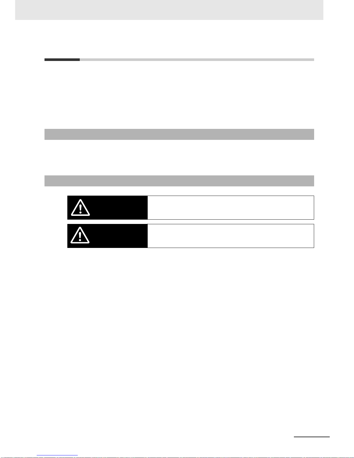
Indications and Meanings of Safety Information
Meanings of Signal Words
Indicates an imminently hazardous situation which, if not avoided, is likely to result in
serious injury or may result in death.
Additionally, there may be severe property damage.
Indicates a potentially hazardous situation which, if not avoided, may result in minor
or moderate injury or in property damage.
WARNING
Caution
Page 12
Safety Precautions
10
High-function General-purpose Inverter 3G3RX-V1 User’s Manual (I578-E1)
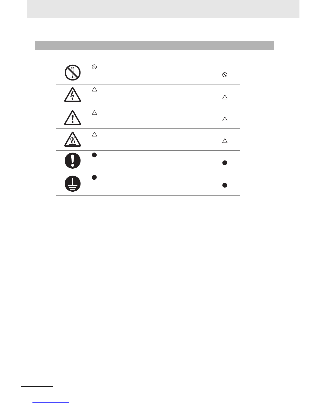
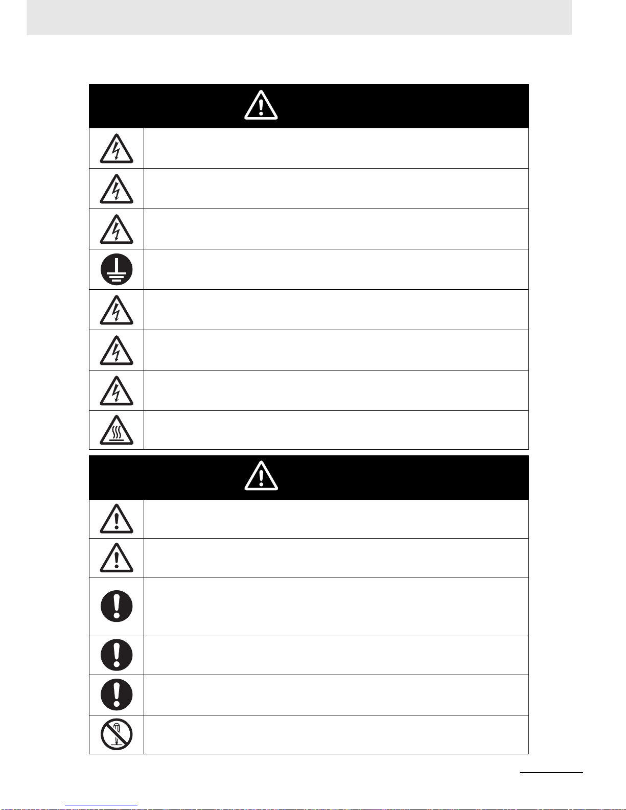
Explanation of Symbols
This symbol indicates a prohibited item (an item you must not do).
The specific instruction is indicated using an illustration or text inside or near .
The symbol shown to the left indicates “disassembly prohibited.”
This symbol indicates danger and caution.
The specific instruction is indicated using an illustration or text inside or near .
The symbol shown to the left indicates “beware of electric shock.”
This symbol indicates danger and caution.
The specific instruction is indicated using an illustration or text inside or near .
The symbol shown to the left indicates “non-specific general danger.”
This symbol indicates caution (including warning).
The specific instruction is indicated using an illustration or text inside or near .
The symbol shown to the left indicates “risk of hot surface.”
This symbol indicates a compulsory item (an item that must be done).
The specific instruction is indicated using an illustration or text inside or near .
The symbol shown to the left indicates “general compulsory items.”
This symbol indicates a compulsory item (an item that must be done).
The specific instruction is indicated using an illustration or text inside or near .
The symbol shown to the left indicates “grounding required.”
Page 13
11
Safety Precautions
High-function General-purpose Inverter 3G3RX-V1 User’s Manual (I578-E1)
Turn off the power supply and implement wiring correctly.
Not doing so may result in a serious injury due to an electric shock.
Wiring work must be carried out only by qualified personnel.
Not doing so may result in a serious injury due to an electric shock.
Do not change wiring and slide switches (SW1), put on or take off Operator and optional devices,
replace cooling fans while the input power is being supplied. Doing so may result in a serious injury
due to an electric shock.
Be sure to ground the unit. Not doing so may result in a serious injury due to an electric shock or
fire.
(200-V class: type-D grounding, 400-V class: type-C grounding)
Do not remove the terminal cover during the power supply and 10 minutes after the power shut off.
Doing so may result in a serious injury due to an electric shock.
Do not operate the Operator or switches with wet hands.
Doing so may result in a serious injury due to an electric shock.
Inspection of the inverter must be conducted after the power supply was turned off. Not doing so
may result in a serious injury due to an electric shock.
The main power supply is not nece ssarily shut off e ven if the emergency shut off function is activated.
Do not touch the inverter fins, braking resistors and the motor, which become too hot during the
power supply and for some time after the power shut off. Doing so may result in a burn.
Do not connect resistors to the terminals (+1, P/+2, N/–) directly. Doing so might result in a
small-scale fire, heat generation, or damage to the unit.
Install a stop motion device to ensure safety. Not doing so might result in a minor injury.
(A holding brake is not a stop motion device designed to ensure safety.)
Be sure to use a specified type of braking resistor/regenerative braking unit. In case of a braking
resistor, install a thermal relay that monitors the temperature of the resistor. Not doing so might
result in a moderate burn due to the heat generated in the braking resistor/regenerative braking
unit. Configure a sequence that enables the inverter power to turn off when unusual over eating is
detected in the braking resistor/regenerative braking unit.
The inverter has high voltage parts inside which, if short-circuited, might cause damage to itself or
other property. Place covers on the openings or take other precautions to make sure that no metal
objects such as cutting bits or lead wire scraps go inside when installing and wiring.
Take safety precautions such as setting up a molded-case circuit breaker (MCCB) that matches the
inverter capacity on the pow er su pp l y sid e.
Not doing so might result in damage to property due to the short circuit of the load.
Do not dismantle, repair or modify the product.
Doing so may result in an injury.
WARNING
Caution
Page 14

Precautions for Safe Use
12
High-function General-purpose Inverter 3G3RX-V1 User’s Manual (I578-E1)
Precautions for Safe Use
Do not store or use the product in the following places.
• Locations subject to direct sunlight.
• Locations subject to ambient temperature exceeding the specifications.
• Locations subject to relative humidit y exceeding the specifications.
• Locations subject to condensation due to severe temperature fluctuations.
• Locations subject to corrosive or flammable gases.
• Locations subject to exposure to combustibles.
• Locations subject to dust (especially iron dust) or salts.
• Locations subject to exposure to water, oil, or chemicals.
• Locations subject to shock or vibration.
• Do not drop or apply strong impact on the product. Doing so may result in damaged parts or
malfunction.
• Do not hold by the front cover and terminal cover, but hold by the fins during transportation.
• Confirm that the rated input voltage of the inverter is the same as AC power supply voltage.
• Do not connect an AC power supply voltage to the control input/output terminals. Doing so may result
in damage to the product.
• Be sure to tighten the screws on the terminal block securely . Wiring work must be done after installing
the unit body.
• Do not connect any load other than a three-phase inductive motor to the U, V, and W output
terminals.
• Take sufficient shielding measures when using the product in the following locations. Not doing so
may result in damage to the product.
Locations subject to static electricity or other forms of noise.
Locations subject to strong magnetic fields.
Locations close to power lines.
• If a parameter is set incorrect ly when starting up , adjusting, maint aining, o r repla cing, a n unexpected
operation may occur. Perform the operation after enough confirmation.
• When using DriveProgramming, confirm that the program data is downloaded normally before
starting operation.
Installation and Storage
Transportation, Installation, and Wiring
Page 15
13
Precautions for Safe Use
High-function General-purpose Inverter 3G3RX-V1 User’s Manual (I578-E1)
• Be sure to confirm the permissible range of motors and machines before operation because the
inverter speed can be changed easily from low to high.
• Provide a separate holding brake if necessary.
• If the DriveProgramming stops during multi-function output, the output status is held. Take safety
precautions such as stopping peripheral device s.
• If the clock command is used in DrivePr ogra mming, an une x pected oper ation may occur due to weak
battery . Take measures such as detect ing a weak ba ttery by a chec k that the cloc k data returns to the
initial setting and stopping the inverter or programs. When the LCD Digital Operator is removed or
disconnected, DriveProgramming is in a waiting status by the clock command.
• Be sure to confirm safety before conduct ing maintenance, inspection or parts replacement.
• The capacitor service life is influenced by the ambi ent temperature. Refer to “Smoothing Capacitor
Life Curve” described in the manual. When a capacitor reaches the end of its service life and does
not work as the product, you need to replace the capacitor.
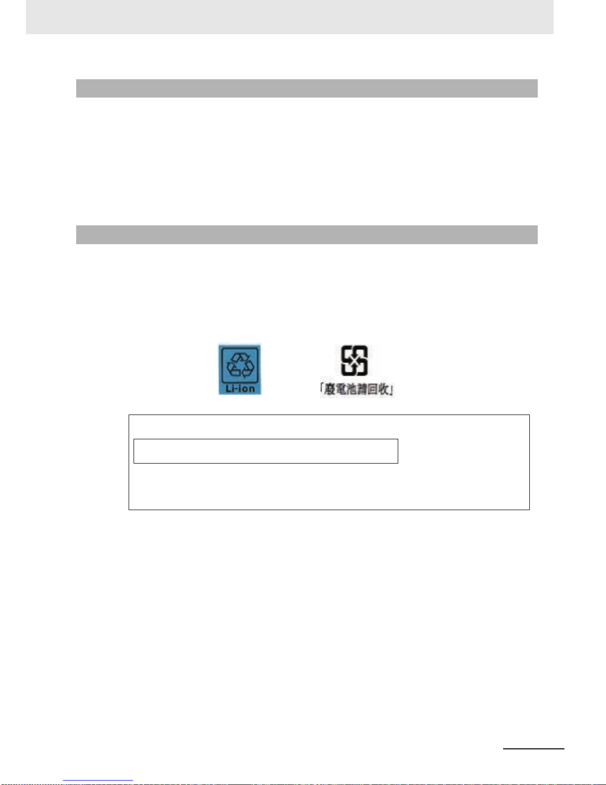
• When disposing of LCD digital operators and wasted batteries, follow the applicable ordinances of
your local government. When disposing of the battery, insulate it using tape.
• Do not short + and –, charge, disassemble, heat, put into the fire, or apply strong impact on the
battery . The bat tery may leak, e x plode , produce hea t or fire . Ne v er use the battery which was applied
strong impact due to such as fall on the floor, it may leak.
• UL standards establish that the batt ery shall be replaced by an expert engineer. The expert engineer
must be in charge of the replacement and a lso replace the battery according to the meth od described
in this manual.
• When the display of LCD Digital Operator can not be recognized due to the service life, replace the
LCD Digital Operator.
Operation and Adjustment
Maintenance and Inspection
The following display must be indicated when products using lithium pr imary batterie s (with
more than 6 ppb of perchlorate) are transport to or through the State of California, USA.
Perchlorate Material - special handling may apply.
See www. dtsc.ca.gov/hazardouswaste/perchlorate
The 3G3AX-OP05 has the lithium primary battery (with more than 6 ppb of perchlorate).
Label or mark the above display on the exterior of all outer shipping packages of your products when exporting your products which the 3G3AX-OP05 are installed to the State of California, USA.
Page 16

Precautions for Correct Use
14
High-function General-purpose Inverter 3G3RX-V1 User’s Manual (I578-E1)
Precautions for Correct Use
Mount the product vertically on a wall with the product’s longer sides upright.
The material of the wall must be noninflammable such as a metal plate.
• Do not come close to the machine when using the Restart Selection function (b001, b008) because
the machine may abruptly start when stopped by an alarm.
• Be sure to confirm the RUN signal is turned off before resettin g the ala rm because the machine may
abruptly start.
Do not come close to the machine when selecting reset in the Deceleration Stop Function (b050)
because the machine may abruptly start after the power is turned on.
• Provide a separate emergency stop switch because the STOP Key on the Operator is valid only when
function settings are performed.
• When checking a signal during the pow er supply and the v oltage is err oneously applied to the contr ol
input terminals, the motor may start abruptly. Be sure to confirm safety before checking a signal.
• Inverters contain components and will operate properly only when each component operates
normally. Some of the electrical components require maintenance depending on application
conditions. Periodic inspection and replacement are necessary to ensure proper long-term operation
of Inverters. (Quoted from The Recommendation for Periodic Maintenance of a General-purpose
Inverter published by JEMA.)
• When a cooling fan reaches the end of its service life, replace it.
Comply with the local ordinance and regulations when disposing of the product.
Installation
Restart Selection Function
Deceleration Stop Function
Operation Stop Command
Maintenance and Parts Replacement
Product Disposal
Page 17
15
Precautions for Correct Use
High-function General-purpose Inverter 3G3RX-V1 User’s Manual (I578-E1)
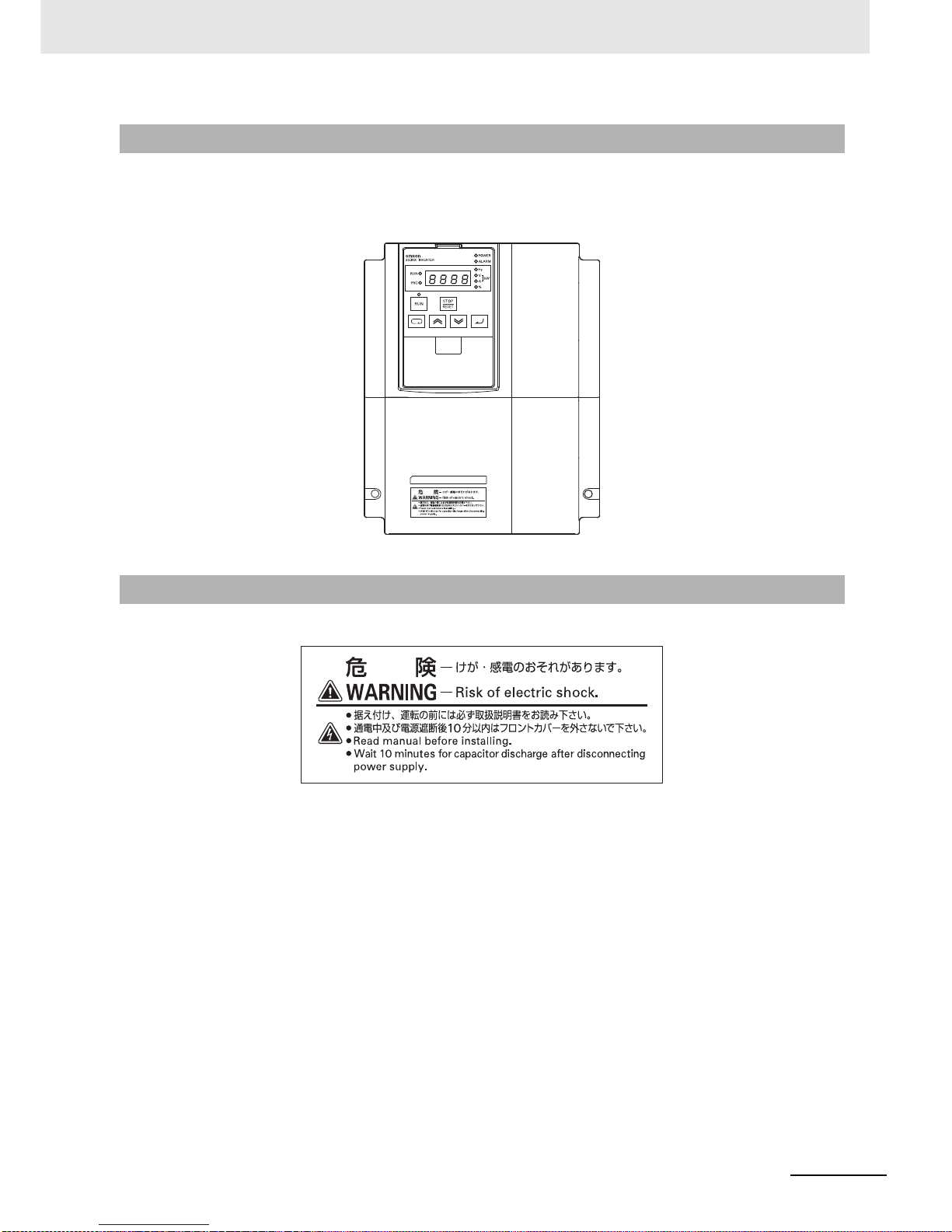
• This product bears a warning label at the follo wing location to provide handling warnings.
• Be sure to follow the instructions.
The appearance differs depending on the capacity of the inv erter.
Warning Label
Warning Description
Page 18

Regulations and Standards
16
High-function General-purpose Inverter 3G3RX-V1 User’s Manual (I578-E1)
Regulations and Standards
To export (or provide to nonresident aliens) any part of this product that falls under the category of
goods (or technologies) for which an export certificate or license is mandatory according to the Foreign
Exchange and Foreign Trade Control Law of Japan, an export certificate or license (or service
transaction approval) according to this law is required.
The 3G3RX-V1 Series complies as standard with both the EC Directives and UL/cUL Standards.
EC Directives and UL/cUL Standards
Standard Applicable Standard
EC Directives EMC Directive EN61800-3: 2004
Low Voltage Directive EN61800-5-1: 2003
UL/cUL Standards UL 508C
Page 19

17
Trademarks
High-function General-purpose Inverter 3G3RX-V1 User’s Manual (I578-E1)
Trademarks
• Windows, Windows 98, Windows XP, Windows Vista, and Windows 7 are re gistered trademarks of
Microsoft Corporation in the USA and other countries.
• DeviceNet is a registered trademark of ODVA (Open DeviceNet Vendor Association).
• CompoNet is a registered trademark of ODVA (Open DeviceNet Vendor Association).
• Other company names and product nam es in this document are the trademarks or registered
trademarks of their respective companies.
Page 20
Items to Check after Unpacking
18
High-function General-purpose Inverter 3G3RX-V1 User’s Manual (I578-E1)
Items to Check after Unpacking
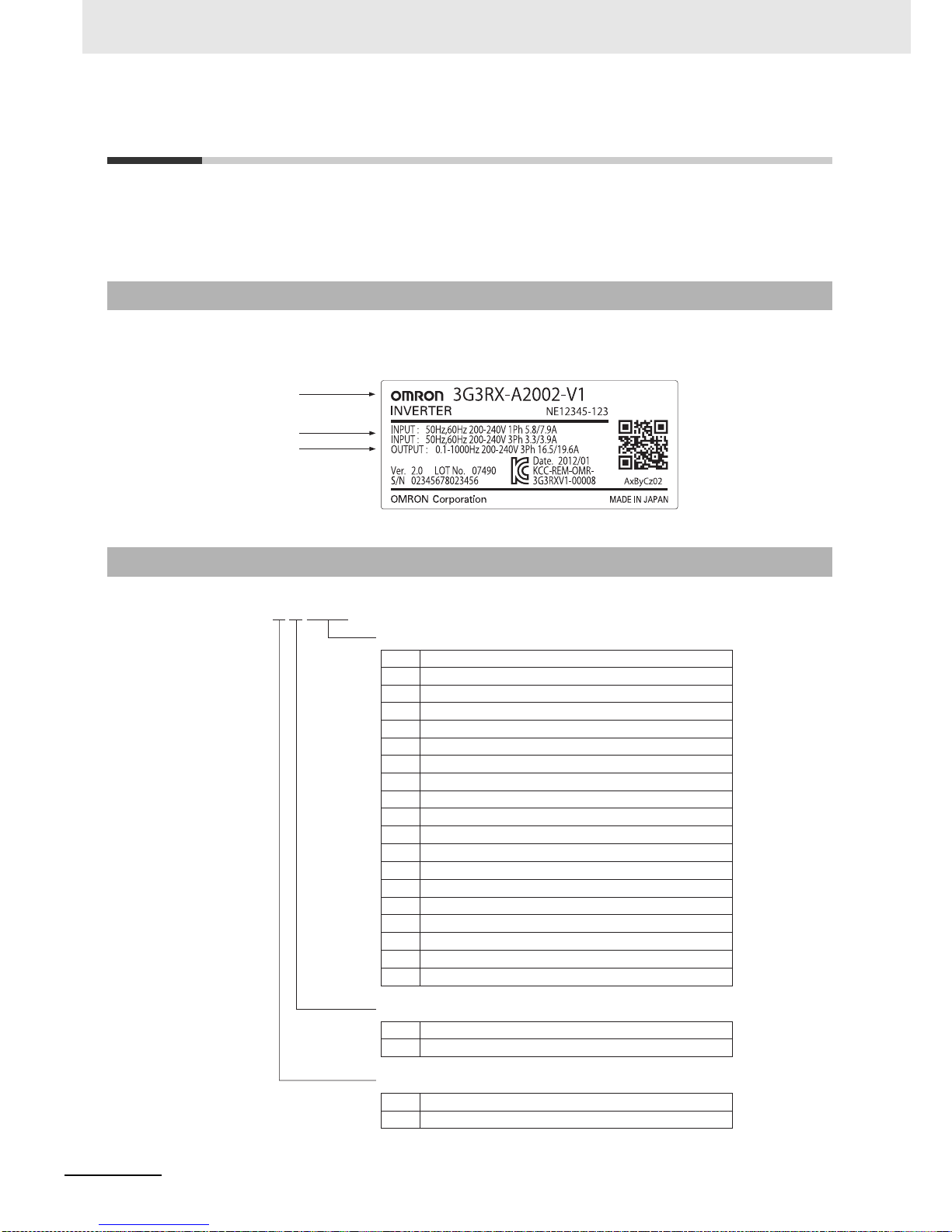
After unpacking, check the following items.
• Is this the model you ordered?
• Was there any damage sustained during shipment?
The nameplate is affixed to the product.
Checking the Nameplate
Checking the Model
Inverter model
Input specifications
Output specifications
3G3RX-A2055-V1
Maximum applicable motor capacity
004
007
015
022
037
055
075
110
150
185
220
300
370
450
550
750
900
11K
13K
0.4 kW
0.75 kW
1.5 kW
2.2 kW
3.7 kW
5.5 kW
7.5 kW
11 k W
15 kW
18.5 kW
22 kW
30 kW
37 kW
45 kW
55 kW
75 kW
90 kW
110 kW
132 kW
Voltage class
243-phase 200 VAC (200-V class)
3-phase 400 VAC (400-V class)
Enclosure rating
A
Panel-mounting (IP20) or closed wall-mounting models
B Panel-mounting (IP00)
Page 21

19
Items to Check after Unpacking
High-function General-purpose Inverter 3G3RX-V1 User’s Manual (I578-E1)
This manual is the only accessory included in the High-function General-purpose Inverter (Model:
3G3RX--V1).
Mounting screws and other necessary parts must be provided by the user.
Checking the Accessories
Page 22

Related Manuals
20
High-function General-purpose Inverter 3G3RX-V1 User’s Manual (I578-E1)
Related Manuals
Please see the manuals below for related product information.
Name Catalog No.
Regenerative Braking Unit 3G3AX-RBU User’s Manual I563
Encorder Feedback Board 3G3AX-PG User’s Manual I564
CX-Drive Operation Manual W453
LCD Digital Operator 3G3AX-OP05 User’s Manual I579
DriveProgramming User’s Manual I580
MX2/RX Series EtherCAT Communication Unit User's Manual I574
MX2/RX Series CompoNet Communications Unit User’s Manual I582
MX2/RX Series DeviceNet Communications Unit User’s Manual I581
Page 23
21
Revision History
High-function General-purpose Inverter 3G3RX-V1 User’s Manual (I578-E1)
Revision History
The manual revision co de is a number appended to the end of the catalog number found in the bottom
right-hand corner of the front and back covers.
Example
Revision code Revision date Revised Content
01 November 2012 Original production
Cat.No. I578-E1-01
Revision code
Page 24

22
High-function General-purpose Inverter 3G3RX-V1 User’s Manual (I578-E1)
CONTENTS
CONTENTS
Introduction ...............................................................................................................1
Intended Readers........................................................................................................................................1
Notice...........................................................................................................................................................1
Manual Configuration ...............................................................................................2
Manual Structure. ......................................................................................................3
Page Structure and Symbol Icons...............................................................................................................3
Special Information.......................................... ................................. ...........................................................4
Sections in this Manual ............................................................................................5
Read and Understand this Manual ..........................................................................6
Safety Precautions....................................................................................................9
Indications and Meanings of Safety Information..........................................................................................9
Meanings of Signal Words...........................................................................................................................9
Explanation of Symbols.............................................................................................................................10
Precautions for Safe Use........................................................................................12
Installation and Storage.............................................................................................................................12
Transportation, Installation, and Wiring .....................................................................................................12
Operation and Adjustment............................................................................................... ... .......................13
Maintenance and Inspection......................................................................................................................13
Precautions for Correct Use...................................................................................14
Installation..................................................................................................................................................14
Restart Selection Function ........................................................................................................................14
Deceleration Stop Function .......................................................................................................................14
Operation Stop Command........................................................ ....................................... ..........................14
Maintenance and Parts Replacement........................................................................................................14
Product Disposal............................................................ ... ................................. ........................................14
Warning Label.......................................................... .................................. ................................................15
Warning Description................................................ ... .................................. .............................................15
Regulations and Standards....................................................................................16
EC Directives and UL/cUL Standards........................................................................................................16
Trademarks..............................................................................................................17
Items to Check after Unpacking.............................................................................18
Checking the Nameplate................................................................................ ... ........................................18
Checking the Model......................................... ................................. .................................. .......................18
Checking the Accessories .........................................................................................................................19
Related Manuals......................................................................................................20
Revision History......................................................................................................21
Section 1 Overview
1-1 Overview of Functions............................................................................................................ 1-2
1-1-1 Features of 3G3RX-V1 Series Inverter.......................................................................................1-2
1-1-2 Classes of 3G3RX-V1 Series Inverter ........................................................................................1-6
1-1-3 Compliance with International Standards (EC Directives and UL/cUL Standards).....................1-7
Page 25

23
High-function General-purpose Inverter 3G3RX-V1 User’s Manual (I578-E1)
CONTENTS
1-2 Appearance and Part Names.................................................................................................. 1-8
1-3 Specifications .......................................................................................................................... 1-9
1-3-1 Standard Specifications.............................................................................................................. 1-9
1-3-2 External Dimensions................................................................................................................. 1-14
1-4 Restrictions............................................................................................................................ 1-23
1-5 Comparison with Previous Model.............................. ... .......................................... ... .... ... ... 1-24
Section 2 Design
Safety Information........................................................................................................................................3
2-1 Installation................................................................................................................................ 2-4
2-1-1 Inverter Installation .....................................................................................................................2-4
2-1-2 Installation Environment ............................................................................................................. 2-4
2-2 Removal of Each P art.............................................................................................................. 2-9
2-2-1 Removing Covers....................................................................................................................... 2-9
2-2-2 Terminal Blocks......................................................................................................................... 2-11
2-2-3 Preparing Bac k ing Plate....................................................................................... ....................2-13
2-3 Wiring ..................................................................................................................................... 2-14
2-3-1 Standard Connection Diagram................................................................................................. 2-14
2-3-2 Arrangement and Function of Main Circuit Terminal Block....................................................... 2-15
2-3-3 Arrangement and Function of Control Circuit Terminal Block................................................... 2-16
2-3-4 Wiring for Main Circuit Terminals.............................................................................................. 2-20
2-3-5 Wiring for Control Circuit Terminals.......................................... ... .. ........................................... 2-43
2-3-6 Wiring for PG Board................................ ... .................................. ................................. ............ 2-49
2-3-7 Wiring for RS485 Communications Terminals .......................................................................... 2-53
2-3-8 Wiring for Digital Operator............................................. .. ... ... ....................................... ............ 2-55
2-3-9 Wiring for Emergency Shutoff Function....................................................... ... ..........................2-56
2-3-10 Conformance to EC Directives ................................................................................................. 2-58
2-3-11 Reference Manuals for Options................................................................................................2-60
Section 3 Operation and Test Run
Precautions for Safe Use..............................................................................................................................2
Precautions for Correct Use.........................................................................................................................3
3-1 Operation of Digital Operator.................................. ... ... .......................................... ... .... ... ... .. 3-4
3-1-1 Part Names and Descriptions.............................................................. ....................................... 3-4
3-1-2 Key Operation Method................................................................................................................3-6
3-2 Overview of LCD Digital Operator........................................................................................ 3-15
3-3 Connections and Functions of CX-Drive............................................................................. 3-16
3-3-1 CX-Drive Connection Method................................................................................................... 3-16
3-3-2 Outline of CX-Drive................................................................................................................... 3-20
3-4 Flow of Test Run.................................................................................................................... 3-24
3-5 Test Run Procedure............................................................................................................... 3-25
Section 4 Parameter List
4-1 Monitor Mode............... .......................................... ... ... ... .......................................... ... ............ 4-2
4-1-1 Group d....................................................................................................................................... 4-2
4-2 Basic Function Mode .............................................................................................................. 4-5
4-2-1 Group F: Basic Function Parameters.......................................................................................... 4-5
4-3 Extended Function Mode ......................................... ... ... .... ......................................... .... ... ..... 4-6
4-3-1 Group A: Standard Function Parameters...................................................................................4-7
4-3-2 Group b: Detailed Function Parameters................................................................................... 4-19
4-3-3 Group C: Multi-function Terminal Function Parameters............................................................4-28
Page 26

24
High-function General-purpose Inverter 3G3RX-V1 User’s Manual (I578-E1)
CONTENTS
4-3-4 Group H: Motor Control Parameters.........................................................................................4-39
4-3-5 Group P: Option Parameters.....................................................................................................4-42
4-3-6 Group U: User Setting Display Parameters...............................................................................4-49
Section 5 Basic Settings
5-1 Parameter Display and Parameter Initialization.................................................................... 5-3
5-1-1 Display Selection........................................... ....................................... .......................................5-3
5-1-2 Parameter Initialization................................................................................................................5-6
5-2 V/f Control Settings.................................................................................................................5-8
5-2-1 Control Method (V/f Characteristics)...........................................................................................5-8
5-2-2 Heavy Load/Light Load Selection ......................................................................... ... ... ... ...........5-12
5-3 Motor Parameter Settings........... ... ... ... ... .... .......................................... ... ... ... .......................5-18
5-3-1 Motor Capacity/Pole Number Selection....................................................................................5-18
5-3-2 Electronic Thermal Function .....................................................................................................5-18
5-4 RUN Command Settings... ... ... .... .......................................... ... ... ... ....................................... 5-23
5-4-1 RUN Command Selection................................................... ... ... ... ....................................... ......5-23
5-5 Frequency Reference Settings.............................................................................................5-24
5-5-1 Frequency Reference Selection................................................................................................5-24
5-5-2 Frequency Limit.........................................................................................................................5-33
5-6 Acceleration/Deceleration Time Settings............................................................................ 5-35
5-6-1 Acceleration/Deceleration Time Settings..................................................................................5-35
5-6-2 Acceleration/Deceleration Pattern.............................................................................................5-37
5-6-3 Automatic Optimum Acceleration/Deceleration.........................................................................5-39
5-6-4 2-step Acceleration/Deceleration Function ................................................ ...............................5-41
5-7 Stop Method Settings............................................................................................................5-43
5-7-1 Stop Selection...........................................................................................................................5-43
5-7-2 Free-run Stop Selection............................................................................................................5-43
5-7-3 STOP Key Selection..................................................................................................................5-46
5-8 Reset Method Settings......................... ... .... ... ... .......................................... ... .... ... ................5-47
5-8-1 Reset.........................................................................................................................................5-47
5-8-2 Restart after Resetting..............................................................................................................5-48
5-9 Multi-function Input Settings................................................................................................5-51
5-9-1 Multi-function Input Selection....................................................................................................5-51
5-9-2 Multi-function Input Operation Selection............................................................................. ... ...5-52
5-9-3 Input Terminal Response Time.................................................................................................5-52
5-9-4 Reverse Command (RV)................................................................. ..........................................5-52
5-9-5 Multi-step Speed Operation Function........................................................................................5-53
5-9-6 Jogging (JG)..............................................................................................................................5-56
5-9-7 2-step Acceleration/Deceleration (2CH)................................................................................5-57
5-9-8 Reset (RS) ........................................................................................... ... ..................................5-57
5-9-9 3-wire Input Function (STA, STP, F/R) ......................................................................................5-58
5-10 Multi-function Output Settings............................................................................................. 5-59
5-10-1 Multi-function Output Selection.................................................................................................5-59
5-10-2 Multi-function Output Operation Selection................................................................................5-60
5-10-3 Multi-function Output ON/OFF Delay Time...............................................................................5-60
5-10-4 Signal during RUN (RUN)......................................................... ... .............................................5-61
5-10-5 Constant Speed Arrival Signal (FA1) ........................................................................................5-61
5-10-6 Alarm Signal (AL)......................................................................................................................5-62
5-10-7 0-Hz Detection Signal (ZS).......................................................................................................5-63
5-10-8 Operation Ready (IRDY) .................... ... .. ........................................ ..........................................5-63
5-10-9 Forward Run Signal (FWR).......................................................................................................5-64
5-10-10 Reverse Run Signal (RVR)........................................................................................................5-64
5-11 Torque Boost Function Settings .......................................................................................... 5-65
5-11-1 Torque Boost....................................................... ................................. .....................................5-65
5-12 Measures against Overvoltage................... .......................................... ... ... ... ....................... 5-68
5-12-1 Overvoltage Suppression Function during Deceleration...........................................................5-68
Page 27

25
High-function General-purpose Inverter 3G3RX-V1 User’s Manual (I578-E1)
CONTENTS
5-12-2 Regenerativ e Br aking Function..................................................... ... ........................................ 5-70
Section 6 Vector Control
6-1 Overview of Vector Control..................................................................................................... 6-2
6-2 Sensorless Vector Control............. ... ... .... ... ... .......................................... ... .... ... ..................... 6-4
6-2-1 Sensorless Vector Control Parameter Settings........................................................................... 6-4
6-2-2 0-Hz Sensorless Vector Control Parameter Settings.................................................................. 6-4
6-2-3 Auto-tuning of Motor Parameters................................................................................................ 6-5
6-2-4 Motor Parameter Settings......................................................................................................... 6-11
6-2-5 Adjustment for Sensorless Vector Control................................................................................6-13
6-2-6 Adjustment for 0 Hz Sensorless Vector Control........................................................................ 6-14
6-3 Sensor Vector Control................. ... ... ... .... .......................................... ... ... ... .......................... 6-15
6-3-1 Sensor Vector Control Parameter Settings...............................................................................6-15
6-3-2 Overview of PG Board............................................. .................................. ...............................6-16
6-3-3 PG Board Function Settings..................................................................................................... 6-17
6-3-4 Auto-tuning of Motor Parameters.............................................................................................. 6-18
6-3-5 Motor Parameter Settings......................................................................................................... 6-24
6-3-6 Adjustment for Sensor Vector Control (Speed Control) ............................................................ 6-26
6-4 Speed Control....... ... .......................................... .... ... ... .......................................... ... ... .......... 6-27
6-4-1 Speed Control Gain Parameters...............................................................................................6-27
6-4-2 P/PI Switching Function............................................................................................................6-28
6-4-3 Control Gain Switching Function ..............................................................................................6-29
6-4-4 Torque Bias Function Settings......................................... ... ... ... ....................................... ......... 6-30
6-5 Torque Limit Function.............. ... ... ... ... .......................................... .... ... ... ... .......................... 6-31
6-5-1 Torque Limit Function Settings ................................................................................................. 6-31
6-5-2 Torque LADST OP Function Settings................................................................. ... .................... 6-33
6-6 Pulse Train Position Control Mode ...................................................................................... 6-34
6-6-1 Pulse Train Position Control Mode Settings.............................................................................. 6-34
6-6-2 Electronic Gear Function............................................... .. ........................................ .................6-36
6-6-3 Position Bias Function..............................................................................................................6-38
6-6-4 Speed Bias Function................................................................................................................. 6-39
6-7 Absolute Position/High-resolution Absolute Position Control Mode............................... 6-40
6-7-1 Absolute Position/High-resolution Absolute Position Control Mode Parameter Settings.......... 6-40
6-7-2 Operation Sequences...............................................................................................................6-43
6-7-3 Origin Search Function.................................................. .. ... ... ....................................... ............ 6-48
6-7-4 Teaching Function.....................................................................................................................6-50
6-7-5 Forward/Reverse Driving Stop and Position Limit Setting Functions........................................6-51
6-8 Orientation Function............................................................................................................. 6-53
6-8-1 Orientation Function Parameter Settings..................................................................................6-53
6-9 Torque Control...................... .... ... ... .......................................... ... ... .... ... ................................ 6-56
6-9-1 Torque Control Parameter Settings...........................................................................................6-56
Section 7 Detailed Functions
7-1 Monitor Mode (Group d).......................................................................................................... 7-2
7-2 Basic Functions (Group F)....................................................................................................7-14
7-3 Basic Functions (Group A)................................................................................................... 7-17
7-4 Detailed Functions (Group b)............................................................................................... 7-61
7-5 Multi-function Terminal Functions (Group C) ...................................................................7-108
7-6 Motor Parameters (Group H) .............................................................................................. 7-145
7-7 Option Functions (Group P)............................................................................................... 7-147
7-8 User Setting Display Functions (Group U)........................................................................ 7-149
Page 28

26
High-function General-purpose Inverter 3G3RX-V1 User’s Manual (I578-E1)
CONTENTS
Section 8 Communications Functions
8-1 Communication Specifications ........... ... .......................................... .... ... ... ............................ 8-2
8-2 Modbus Method.......................................................................................................................8-6
8-3 Explanation of Each Function Code....................................................................................8-10
8-4 Saving a Change to Holding Register (Enter Command) .................................................. 8-20
8-5 Modbus Communication Register Number List ................................................................. 8-22
8-5-1 Coil Number List........................................................................................................................8-22
8-5-2 Monitor Function/Enter Command Register List.......................................................................8-27
8-5-3 Group F Register List................................................................ ... ... ..........................................8-37
8-5-4 Group A/b/C/H/P Register List................................................................................. ... ..............8-38
8-5-5 2nd Control Register Number List.............................................................................................8-71
8-5-6 3rd Control Register Number List..............................................................................................8-75
8-6 ASCII Method ......................................................................................................................... 8-77
8-6-1 Communications Procedure......................................................................................................8-77
8-6-2 Communications Commands....................................................................................................8-78
Section 9 Overview of DriveProgramming
9-1 Overview of DriveProgramming.............................................................................................9-2
Section 10 Troubleshooting
10-1 Alarm Codes and Remedies ................................................................................................. 10-2
10-1-1 Alarm Display........................................................... .................................. ...............................10-2
10-1-2 Alarm Code List ........................................................................................................................10-3
10-1-3 Option Board Protective Function List.......................................................................................10-9
10-2 Warning Function ....... .... ... ... ... .......................................... .... ... ... ........................................10-12
10-3 Other Indications on Digital Operator................................................................................10-14
10-4 Troubleshooting................................................................................................................... 10-15
Section 11 Maintenance and Inspection
Precautions for Safe Use.............................................................................................................................2
Precautions for Correct Use ........................................................................................................................3
11-1 Inspection............................................................................................................................... 11-4
11-1-1 Daily Inspection.........................................................................................................................11-4
11-1-2 Periodic Inspection....................................................................................................................11-4
11-1-3 Inspection Items........................................................................................................................11-5
11-2 Cleaning ................................................................................................................................. 11-8
11-3 Test Methods.......................................................................................................................... 11-9
11-3-1 Megger Test ..............................................................................................................................11-9
11-3-2 Withstand Voltage Test..............................................................................................................11-9
11-3-3 Inverter/Converter Unit Test....................................................................... ... ..........................11-10
11-3-4 I/O Voltage/Current/Electric Power Measurement Method......................................................11-12
Section 12 Options
12-1 Overview of Optional Equipment ............................................................... ... .... ... ... ... ..........12-3
12-1-1 Part Names and Descriptions...................................................................................................12-3
12-2 Regenerative Braking Unit (Model: 3G3AX-RBU)......................................................... 12-5
Page 29

27
High-function General-purpose Inverter 3G3RX-V1 User’s Manual (I578-E1)
CONTENTS
12-2-1 Specifications............................................................................................................................ 12-5
12-2-2 External Dimensions.................................................................................................................12-7
12-2-3 Connection Examples.............................................. ....................................... ........................12-11
12-3 Braking Resistor (Model: 3G3AX-RBA/RBB/RBC)............................................... 12-12
12-3-1 Specifications.......................................................................................................................... 12-12
12-3-2 External Dimensions...............................................................................................................12-13
12-3-3 Connection Example.................... ... ....................................... ... .............................................. 12-15
12-4 Regenerative Braking Unit and Braking Resistor Combination Selection Table .......... 12-16
12-5 DC Reactor (Model: 3G3AX-DL) ............................................................................ 12-23
12-5-1 Specifications.......................................................................................................................... 12-23
12-5-2 External Dimensions...............................................................................................................12-25
12-5-3 Connection Examples.............................................. ....................................... ........................12-28
12-6 AC Reactor (Model: 3G3AX-AL)............................................................................. 12-29
12-6-1 Specifications.......................................................................................................................... 12-29
12-6-2 External Dimensions...............................................................................................................12-31
12-6-3 Connection Examples.............................................. ....................................... ........................12-32
12-7 Input Noise Filter (Model: 3G3AX-NFI)........................................................................ 12-33
12-7-1 Specifications.......................................................................................................................... 12-33
12-7-2 External Dimensions...............................................................................................................12-35
12-7-3 Connection Examples.............................................. ....................................... ........................12-40
12-8 Output Noise Filter (Model: 3G3AX-NFO)................................................................... 12-41
12-8-1 Specifications.......................................................................................................................... 12-41
12-8-2 External Dimensions...............................................................................................................12-43
12-8-3 Connection Example.................... ... ....................................... ... .............................................. 12-44
12-9 Radio Noise Filter (Model: 3G3AX-ZCL).........................................................................12-45
12-9-1 Specifications.......................................................................................................................... 12-45
12-9-2 External Dimensions...............................................................................................................12-46
12-9-3 Connection Example.................... ... ....................................... ... .............................................. 12-47
12-10EMC Noise Filter (Model: 3G3AX-EFI)......................................................................... 12-48
12-10-1 Specifications..........................................................................................................................12-48
12-10-2 External Dimensions...............................................................................................................12-50
12-10-3 Connection Example........................................................... ... ....................................... .......... 12-52
12-11Digital Operator (Model: 3G3AX-OP01/
OP05
).................................................................... 12-53
12-11-1 Specifications..........................................................................................................................12-53
12-11-2 External Dimensions...............................................................................................................12-54
12-12Digital Operator Cable (Model: 3G3AX-OPCN).............................................................. 12-56
12-12-1 Specifications..........................................................................................................................12-56
12-12-2 External Dimensions...............................................................................................................12-56
12-13PG Board (Model: 3G3AX-PG01)........................................................................................ 12-57
12-13-1 Specifications..........................................................................................................................12-57
12-13-2 External Dimensions...............................................................................................................12-58
12-13-3 Connection Examples.................................................................................. ... ........................12-58
12-14EtherCAT Communications Unit (Model: 3G3AX-RX-ECT).............................................. 12-59
12-14-1 Specifications..........................................................................................................................12-59
12-14-2 External Dimensions...............................................................................................................12-60
12-15CompoNet Communications Unit (Model: 3G3AX-RX-CRT-E)......................................... 12-61
12-15-1 Specifications..........................................................................................................................12-61
12-15-2 External Dimensions...............................................................................................................12-62
12-16DeviceNet Communications Unit (Model: 3G3AX-RX-DRT-E) ......................................... 12-63
12-16-1 Specifications..........................................................................................................................12-63
12-16-2 External Dimensions...............................................................................................................12-64
Appendices
A-1 Smoothing Capacitor Life Curve............................................................................................A-2
Page 30

28
High-function General-purpose Inverter 3G3RX-V1 User’s Manual (I578-E1)
CONTENTS
A-2 Life Alarm Output ..................................................... ... ... .......................................... ... ... .........A-3
A-3 Packing Dimensions and Weight ..... ... ... .... .......................................... ... ... ... .... .....................A-4
A-4 Overview of Inverter Selection ... ... ... ... ... .......................................... .... ... ... ... .........................A-5
Index
Page 31

1 - 1
1
High-function General-purpose Inverter 3G3RX-V1 User’s Manual (I578-E1)
This section provides an overview of the 3G3RX-V1 Series features, standard
specifications, and external dimensions by inverter capacity. It also shows the
differences of this in verter from the con ventiona l inv erter for those who use t he prev ious
model.
1-1 Overview of Functions . . . . . . . . . . . . . . . . . . . . . . . . . . . . . . . . . . . . . . . . . . 1-2
1-1-1 Features of 3G3RX-V1 Series Inverter . . . . . . . . . . . . . . . . . . . . . . . . . . . . . . 1-2
1-1-2 Classes of 3G3RX-V1 Series Inverter . . . . . . . . . . . . . . . . . . . . . . . . . . . . . . . 1-6
1-1-3 Compliance with Intern ational Standards
(EC Directives and UL/cUL Standards) . . . . . . . . . . . . . . . . . . . . . . . . . . . . . . 1-7
1-2 Appearance and Part Names . . . . . . . . . . . . . . . . . . . . . . . . . . . . . . . . . . . . 1-8
1-3 Specifications . . . . . . . . . . . . . . . . . . . . . . . . . . . . . . . . . . . . . . . . . . . . . . . . . 1-9
1-3-1 Standard Specifications . . . . . . . . . . . . . . . . . . . . . . . . . . . . . . . . . . . . . . . . . . 1-9
1-3-2 External Dimensions . . . . . . . . . . . . . . . . . . . . . . . . . . . . . . . . . . . . . . . . . . . 1-14
1-4 Restrictions . . . . . . . . . . . . . . . . . . . . . . . . . . . . . . . . . . . . . . . . . . . . . . . . . 1-23
1-5 Comparison with Previous Model . . . . . . . . . . . . . . . . . . . . . . . . . . . . . . . 1-24
Overview
Page 32

1 Overview
1 - 2
High-function General-purpose Inverter 3G3RX-V1 User’s Manual (I578-E1)
1-1 Overview of Functions
The High-function General-purpose Inverter (Model: 3G3RX--V1) is a human- and
environmental-friendly inverter suitable for a variety of applications. It provides various features, such
as convenient functions intended for ease of use, network support, and diverse I/O.
In addition, the 3G3RX-V1 Series complies as standard with both the EC Directives and UL/cUL
Standards. You can use this product as a world standard inverter.
The 3G3RX-V1 Series Inverter has the following f eatures.
The 3G3RX-V1 Series provides high performance and high functionality, which are the requirements of
a general-purpose inverter.
It enhances the capability to support applications and addresses diverse needs with optimal
performance.
Addition of the dual rating function (heavy load and light load)
In addition to the conventional heavy load mode, the 3G3RX-V1 Series Inverter newly has the light
load mode to provide the dual ra ting function.
The light load mode is available for a fan, pump, or other device that operates at the rated motor
torque or less in a normal state. Setting the light load mode causes the rated current of the inverter
to increase, enabling the inverter to drive a motor that is one size larger in capacity.
However, pay attention to when selecting an inverter because the overload capacity decreases to
1 minute, 120% of the rated current.
Precautions for Correct UsePrecautions for Correct Use
Switching between the heavy load mode and the light loa d mode changes the se tting ranges and
default datas of the relate d parameters . Ref er to 5-2-2 He avy Load/Light Load Selection on page
5-12 for details.
Implementation of the programming function
The 3G3RX-V1 Series has the buit-in simple sequen ce function (DriveProg ramming), which enab les
a stand-alone inverter to perform simple sequence control.
You can create programs easily in flowchart or text language method by using the CX-Drive.
For details, refer to “DriveProgramming User’s Manual (I580)”.
1-1-1 Features of 3G3RX-V1 Series Inverter
Enhanced Application Support
Page 33

1 - 3
1 Overview
High-function General-purpose Inverter 3G3RX-V1 User’s Manual (I578-E1)
1-1 Overview of Functions
1
1-1-1 Features of 3G3RX-V1 Series Inverter
Implementation of the vector control functions
With sensorless vector control, the inverter realizes a high starting torque at 200% of the motor
rating in 0.3 Hz.
With 0-Hz sensorless vector control, the inverter can also output a high starting torque at 150% of
the motor rating in even lower frequencies.
The inverter has various vector control functions as listed below, in addition to V/f control.
• Sensorless vector control
• 0-Hz sensorless vector control
• Sensor vector control
Availability of position control by the feedback
The inverter can realize accurate po sition contr ol b y feeding back the load -side position inf ormation,
just like a servo system. It is effective to save costs for the whole sysytem because the position
control system with a motor over 15 kW is available, and also other position controllers are
unnecessary if the inverter’s internal position control function is used.
This inverter has the follo wing position control functions.
• Absolute position control mode and high-resolut ion absolute position control mode that can
control up to 8 points
• Pulse train position control mode that can control via pulse input from the host controller
• Orientation function that controls a rotating shaft to stop at a fixed position
PID control function
The inverter provides PID control that adjusts the feedback value to match the target value.
This is available to the process control such as temperature, pressure, flow rate without temperature
controller or external controller.
Power interruption restart function
If a momentary power interruption occurs during operation, th e inv erter automatically recognizes the
rotation speed of the motor at power recovery, without detecting undervoltage, to enab le a smooth
restart.
Stall prevention function
Induction motors may stall (or step out) if a large load is applied due to rapid acceleration or load
fluctuation.
This inverter has the overload limit function that prevents such a stall condition and ensures a
persistent operation.
Page 34

1 Overview
1 - 4
High-function General-purpose Inverter 3G3RX-V1 User’s Manual (I578-E1)
The 3G3RX-V1 Series Inverter contributes to the reduction of man-hours in all phases of
inverter-related work: from wiring, parameter setting, operation, throug h to maintenance.
Removable Digital Operator as standard equipment
This inverter has a removable Digital Operator as standard equipment.
By connecting the optional special cable, it is possible to operate th e Digital Operator at hand or
install it to the front face of the control panel. This is convenient during setup or maintenance
operation.
The operability of the keys and the method to initialize parameters were changed to the same as
those for the 3G3MX2 Series .
Addition of the initial screen automatic return function
The inverter newly has the “initial scree n automatic return function” which aut omatically swit ches the
screen to the initial screen if the Digital Operator is not operated for 10 minut es.
5-line LCD Digital Operator
This inverter supports the newly released LCD Digital Operat or 3G3AX-OP05 wit h the 5-line d isplay
capability. The LCD Digital Operator can display four monitor functions or parameter settings in the
selected language (currently English only), which effectively improves the readability of the device
status and other information.
In addition, the LCD Digital Operator can store up to f our sets of in verter parameter setting dat a, or a
single set of inverter parameter setting data an d a single DriveProgramming prog ram in its internal
memory . This sa v es t ime when y ou set the same param eter or write the same prog ram t o more t han
one inverter.
Removable control terminal block
The removable control circuit terminal block enable s you to replace an Unit with wiring connected,
which facilitates the maintenance and inspection of the inverter.
Emergency shutoff function
This function enables to shut off output by the hardware without the software, which can provide
more reliable emergency shutoff operation.
Modbus comm unication function as standard
The inverter has the RS485 communications circuit and the Modbus communication protocol as
standard.
You can use Modbus communication to control and monitor the inverter status, or read and write
various parameter settings.
Change of default parameter setting
The default parameter setting of the conventional 3G3RX Series Inverter were reviewed and were
changed according to the user’s usage. Some functions are enabled by default for reducing the
workload of the user.
The default parameter setting changed in the 3G3RX-V1 Series are shown in Section 4 Parameter
List. Check if these are appropriate for your application.
Ease of Use
Page 35

1 - 5
1 Overview
High-function General-purpose Inverter 3G3RX-V1 User’s Manual (I578-E1)
1-1 Overview of Functions
1
1-1-1 Features of 3G3RX-V1 Series Inverter
Simplified parameter setting by user parameters
This inverter provides User Selection 1 to 12 (U001 to U012) as user parameters. You can register
parameters that are frequently used to simplify the parameter setting and adjustment.
It is also possible to automatically register changed parameters as user parameters.
Open field network
Installing any of the following optional communications units enables the inverter to support the
corresponding open network.
It means that the host of each communications unit can pe rform the in verter operations, sto p control,
status monitor, and functions to read and write various parameter settings.
• EtherCAT Communications Unit (Model: 3G3AX-RX-ECT)
• CompoNet Communications Unit (Model: 3G3AX-RX-CRT-E)
• DeviceNet Communications Unit (Model: 3G3AX-RX-DRT-E)
OMRON gives consideration to not only the inverter, but also the service life and energy efficiency of
the connected motor.
This inverter, as a standard product, complies with the RoHS directive and international standards to
realize an environmental-friendly inverter.
Measures against noise and harmonic interference for peripheral protection
The inverter has the built-in EMC noise filter as standard as a measure ag ainst noise for compliance
with the EMC directive.
Long life design
The inverter has a design life of 10 years through the use of long-life pars for its capacito rs , fan, and
other consumables. Using an inverter for a longer period than ever before has an advantage in
extending the life of your facility.
Automatic energy-saving function
The automatic energy-saving function automatically adjusts the output power of the inverter
operating at a constant speed to the minimum. I t has an energ y-sa ving eff ect in applica tions such as
a fan or pump.
Compliance with safety standards
The inverter complies as standard with the EC Directiv es and UL/cUL Standards.
Complies with RoHS Directive
This inverter, as a standard product, complies with the RoHS Directive that restricts the use of six
hazardous substances.
Environmental Consideration
Page 36

1 Overview
1 - 6
High-function General-purpose Inverter 3G3RX-V1 User’s Manual (I578-E1)
There are two voltage classes for 3G3RX-V1 Series Inverters: 3-phase 200 VA C and 3-phase 400 VAC.
The applicable motor capacity is 0.4 to 132 kW.
All models comply as standard with the EC Directives and UL/cUL Standards.
1-1-2 Classes of 3G3RX-V1 Series Inverter
Rated voltage Enclosure rating
Max. applicable motor
capacity
Model
3-phase 200 VAC IP20
0.4 kW 3G3RX-A2004-V1
0.75 kW 3G3RX-A2007-V1
1.5 kW 3G3RX-A2015-V1
2.2 kW 3G3RX-A2022-V1
3.7 kW 3G3RX-A2037-V1
5.5 kW 3G3RX-A2055-V1
7.5 kW 3G3RX-A2075-V1
11 kW 3G3RX-A2110-V1
15 kW 3G3RX-A2150-V1
18.5 kW 3G3RX-A2185-V1
22 kW 3G3RX-A2220-V1
30 kW 3G3RX-A2300-V1
37 kW 3G3RX-A2370-V1
45 kW 3G3RX-A2450-V1
55 kW 3G3RX-A2550-V1
3-phase 400 VAC
IP20
0.4 kW 3G3RX-A4004-V1
0.75 kW 3G3RX-A4007-V1
1.5 kW 3G3RX-A4015-V1
2.2 kW 3G3RX-A4022-V1
3.7 kW 3G3RX-A4037-V1
5.5 kW 3G3RX-A4055-V1
7.5 kW 3G3RX-A4075-V1
11 kW 3G3RX-A4110-V1
15 kW 3G3RX-A4150-V1
18.5 kW 3G3RX-A4185-V1
22 kW 3G3RX-A4220-V1
30 kW 3G3RX-A4300-V1
37 kW 3G3RX-A4370-V1
45 kW 3G3RX-A4450-V1
55 kW 3G3RX-A4550-V1
IP00
75 kW 3G3RX-B4750-V1
90 kW 3G3RX-B4900-V1
110 kW 3G3RX-B411K-V1
132 kW 3G3RX-B413K-V1
Page 37

1 - 7
1 Overview
High-function General-purpose Inverter 3G3RX-V1 User’s Manual (I578-E1)
1-1 Overview of Functions
1
1-1-3 Compliance with International Standards (EC Directives and UL/cUL Standards)
The 3G3RX-V1 Series complies as standard with both the EC Directives and UL/ cUL Standards. You
can use this product as a world standard inverter.
Checking the Model
1-1-3 Compliance with International Standards
(EC Directives and UL/cUL Standards)
Standard Applicable Standard
EC Directives EMC Directive EN61800-3: 2004
Low Voltage Directive EN61800-5-1: 2003
UL/cUL Standards UL 508C
3G3RX–A2055–V1
Maximum applicable motor capacity
004
007
015
022
037
055
075
110
150
185
220
300
370
450
550
750
900
11K
13K
0.4 kW
0.75 kW
1.5 kW
2.2 kW
3.7 kW
5.5 kW
7.5 kW
11 k W
15 kW
18.5 kW
22 kW
30 kW
37 kW
45 kW
55 kW
75 kW
90 kW
110 kW
132 kW
Voltage class
243-phase 200 VAC (200-V class)
3-phase 400 VAC (400-V class)
Enclosure rating
A Panel-mounting (IP20) or closed wall-mounting models
B Panel-mounting (IP00)
Page 38

1 Overview
1 - 8
High-function General-purpose Inverter 3G3RX-V1 User’s Manual (I578-E1)
1-2 Appearance and Part Names
The following shows the front view when the product is unpacked (an example of
3G3RX-A2055-V1/A2075-V1/A2110-V1/A4055-V1/A4075-V1/A4110-V1).
Open the terminal block cover to wire the main circuit terminal block and the control circuit terminal
block.
Moreover, you can open the front cover to mount option boards.
Digital Operator
Data Display
Front Cover
Spacer Cover
Terminal Block Cover
Use this to set parameters, view various monitor data,
run/stop the inverter, etc.
This displays the frequency reference value, output
frequency, parameter set value, or other relevant data.
Remove this to mount option boards.
Remove this to mount optional units or 5-line LCD Digital
Operator.
Remove this when connecting cables to each terminal
block.
Connector for mounting option board 1
Connector for mounting option board 2
Use this to connect an option board.
Use this to connect an option board or
communications unit.
Control circuit terminal block
Use this to connect various digital/analog I/O signals
for inverter control.
Backing plate
Cut off the cutout portions of this plate to connect
power supply lines, signal lines, etc.
Main circuit terminal block
Use this to connect the inverter main power supply,
motor, braking resistor, and other devices.
Page 39

1 - 9
1 Overview
High-function General-purpose Inverter 3G3RX-V1 User’s Manual (I578-E1)
1-3 Specifications
1
1-3-1 Standard Specifications
1-3 Specifications
CT: Heavy load mode, VT: Light load mode
1-3-1 Standard Specifications
3-phase 200-V Class
Item
Model (3G3RX)
A2004-V1 A2007-V1 A2015-V1 A2022-V1 A2037-V1 A2055-V1 A2075-V1 A2110-V1
Maximum applicable motor
capacity [kW]
CT 0.4 0.75 1.5 2.2 3.7 5.5 7.5 11
VT 0.75 1.5 2.2 3.7 5.5 7.5 11 15
Rated output capacity
[kVA]
200 V
CT 1.0 1.7 2.5 3.6 5.7 8.3 11.0 15.9
VT 1.2 2.1 3.2 4.1 6.7 10.3 15.2 20.0
240 V
CT 1.2 2.0 3.1 4.3 6.8 9.9 13.3 19.1
VT 1.5 2.6 3.9 4.9 8.1 12.4 18.2 24.1
Rated input voltage 3-phase: 200 V –15% to 240 V 10%, 50/60 Hz ±5%
Rated input current [A]
CT3.35.58.31218263551
VT 3.9 7.2 10.8 13.9 23 37 48 64
Rated output voltage 3-phase: 200 to 240 V (Cannot exceed that of incoming voltage)
Rated output current [A]
CT 3.0 5.0 7.5 10.5 16.5 24 32 46
VT3.76.39.41219.6304458
EMC noise filter Built-in (EMC Directive EN61800-3 Category C3)
Weight [kg] 3.5 3.5 3.5 3.5 3.5 6 6 6
Braking
Regenerative braking Built-in braking resistor circuit (Discharge resistor separately mounted)
Minimum connection
resistance [Ω]
50 50 35 35 35 16 10 10
Maximum
leakage
current [mA]
EMC filter enabled 2.5 48
EMC filter disabled 0.1
Item
Model (3G3RX)
A2150-V1 A2185-V1 A2220-V1 A2300-V1 A2370-V1 A2450-V1 A2550-V1
Maximum applicable motor capacity [kW]
CT1518.52230374555
VT18.5223037455575
Rated input capacity [kVA]
200 V
CT 22.1 26.3 32.9 41.9 50.2 63.0 76.2
VT 25.2 29.4 39.1 48.5 58.5 72.7 93.5
240 V
CT 26.6 31.5 39.4 50.2 60.2 75.6 91.4
VT 30.3 35.3 46.9 58.1 70.2 87.2 112.2
Rated input voltage 3-phase: 200 V –15% to 240 V 10%, 50/60 Hz ±5%
Rated input current [A]
CT 70 84 105 133 160 200 242
VT 80 94 120 150 186 240 280
Rated output voltage 3-phase: 200 to 240 V (Cannot exceed that of incoming voltage)
Rated output current [A]
CT 64 76 95 121 145 182 220
VT 73 85 113 140 169 210 270
EMC noise filter Built-in (EMC Directive EN61800-3 Category C3)
Weight [kg] 14 14 14 22 30 30 43
Braking
Regenerative braking
Built-in braking resistor circuit
(discharge resistor separately mounted)
Regenerative braking unit separately mounted
Minimum connection
resistance [
Ω]
7.5 7.5 5
–
Maximum leakage
current [mA]
EMC filter enabled 23
EMC filter disabled 0.1
Page 40

1 Overview
1 - 10
High-function General-purpose Inverter 3G3RX-V1 User’s Manual (I578-E1)
CT: Heavy load mode, VT: Light load mode
3-phase 400-V Class
Item
Model (3G3RX)
A4004
-V1
A4007
-V1
A4015
-V1
A4022
-V1
A4037
-V1
A4055
-V1
A4075
-V1
A4110
-V1
A4150
-V1
A4185
-V1
A4220
-V1
Maximum applicable motor
capacity [kW]
CT 0.4 0.75 1.5 2.2 3.7 5.5 7.5 11 15 18.5 22
VT 0.75 1.5 2.2 3.7 5.5 7.5 11 15 18.5 22 30
Rated output capacity
[kVA]
400 V
CT 1.0 1.7 2.6 3.6 6.2 9.6 13.1 17.3 22.1 26.3 33.2
VT 1.3 2.1 3.3 4.6 7.6 11.0 15.2 20.0 25.6 29.7 39.4
480 V
CT 1.2 2.0 3.1 4.4 7.4 11.6 15.7 20.7 26.6 31.5 39.9
VT 1.5 2.5 3.9 5.5 9.2 13.3 18.2 24.1 30.7 35.7 47.3
Rated input voltage 3-phase: 380 V –15% to 480 V 10%, 50/60 Hz ±5%
Rated input current [A]
CT1.82.84.25.89.8152128354253
VT2.14.35.98.113.3202432414763
Rated output voltage 3-phase: 380 to 480 V (Cannot exceed that of incoming voltage)
Rated output current [A]
CT1.52.53.85.39.0141925323848
VT1.93.14.86.711.1162229374357
EMC noise filter Built-in (EMC Directive EN61800-3 Category C3)
Weight [kg] 3.53.53.53.53.5666141414
Braking
Regenerative braking Built-in braking resistor circuit (Discharge resistor separately mounted)
Minimum connection
resistance [Ω]
100 100 100 100 70 70 35 35 24 24 20
Maximum
leakage
current [mA]
EMC filter enabled
59556
EMC filter disabled
0.2
Item
Model (3G3RX)
A4300
-V1
A4370
-V1
A4450
-V1
A4550
-V1
A4750
-V1
B4900
-V1
B411K
-V1
B413K
-V1
Maximum applicable motor
capacity [kW]
CT 30 37 45 55 75 90 110 132
VT 37 45 55 75 90 110 132 160
Rated output capacity
[kVA]
400 V CT 40.1 51.9 63.0 77.5 103.2 121.9 150.3 180.1
VT 48.4 58.8 72.7 93.5 110.8 135 159.3 200.9
480 V CT 48.2 62.3 75.6 93.1 123.8 146.3 180.4 216.1
VT 58.1 70.6 87.2 112.2 133 162.1 191.2 241.1
Rated input voltage 3-phase: 380 V –15% to 480 V 10%, 50/60 Hz ±5%
Rated input current [A]
CT 64 83 100 121 164 194 239 286
VT 77 94 116 149 176 199 253 300
Rated output voltage 3-phase: 380 to 480 V (Cannot exceed that of incoming voltage)
Rated output current [A]
CT 58 75 91 112 149 176 217 260
VT 70 85 105 135 160 195 230 290
EMC noise filter Built-in (EMC Directive EN61800-3 Category 3)
Weight [kg] 22 30 30 30 55 55 70 70
Braking
Regenerative braking Regenerative braking unit separately mounted
Minimum connection
resistance [Ω]
–
Maximum
leakage
current [mA]
EMC filter enabled 56
0.2 (No enabled/disabled setting
available)
EMC filter disabled 0.2
Page 41

1 - 11
1 Overview
High-function General-purpose Inverter 3G3RX-V1 User’s Manual (I578-E1)
1-3 Specifications
1
1-3-1 Standard Specifications
Common Specifications
Item Specifications
Enclosure rating
IP20 (0.4 to 55 kW)
IP00 (75 to 132 kW)
Control method Phase-to-phase sinusoidal modulation PWM
Output frequency range 0.1 to 400 Hz
Frequency precision
Digital command: ±0.01% of the maximum frequency, Analog command: ±0.2% of
the maximum frequency (25±10°C)
Frequency resolution
Digital setting: 0.01 Hz
Analog setting:
Maximum frequency/4000 (Terminal FV: 12 bits/0 to 10 V),
(Terminal FE: 12 bits/–10 to 10 V), (Terminal FI: 12 bits/0 to 20 mA)
Voltage/Frequency characteristics
Heavy load (CT):
V/f characteristics (constant torque, reduced torque, free V/f
setting), sensorless vector control, 0-Hz sensorless vector
control, sensor vector control
Light load (VT): V/f characteristics (constant torque, reduced torque, free V/f
setting), sensorless vector control
Overload current rating
Heavy load (CT):
150%/60 s, 200%/3 s (180%/3 s for 75 kW or more)
Light load (VT): 120%/60 s, 150%/5 s
Instantaneous overcurrent protection 200% of heavy load rating (CT) value
Acceleration/Deceleration time 0.01 to 3600.0 s (line/curve setting)
Speed fluctuation
Heavy load (CT):
±0.5% *1
*2
Light load (VT):
±0.5%
*1
Carrier frequency change range
<For 0.4 to 55 kW> <For 75 to 132 kW>
Heavy load (CT):
0.5 to 15 kHz
Heavy load (CT):
0.5 to 10 kHz
Light load (VT): 0.5 to 12 kHz Light load (VT): 0.5 to 8 kHz
Starting torque
Sensorless
vector control
<For 0.4 to 55 kW> <For 75 to 132 kW>
Heavy load (CT):
200%/0.3 Hz
*1
Heavy load (CT):
180%/0.3 Hz
*1
Light load (VT):
150%/0.5 Hz
*1
Light load (VT):
120%/0.5 Hz
*1
0-Hz sensorless
vector control
<For 0.4 to 55 kW> <For 75 to 132 kW>
Heavy load (CT):
150%/Torque at 0 Hz
*3
Heavy load (CT):
130%/Torque at 0 Hz
*3
Light load (VT): No function available Light load (VT): No function available
DC injection braking
Operates when the starting frequency is lower than that in deceleration via the
STOP command, when the frequency reference is lower than the operation
frequency, or via an external input (braking power, time, and frequency are
adjustable)
Protective functions
Overcurrent protection, Overvoltage protection, Undervoltage protection,
Electronic thermal protection, Temperature error protection, Momentary power
interruption/Power interruption protection, Input phase loss protection, Braking
resistor overload protection, Ground-fault current detection at power-on, USP
error, External trip, Emergency shutoff trip, CT error, Communication error, Option
error, etc.
Page 42

1 Overview
1 - 12
High-function General-purpose Inverter 3G3RX-V1 User’s Manual (I578-E1)
Input
signal
Frequency
settings
Standard Digital
Operator
Setting via / keys
External signal
*4
0 to 10 VDC, –10 to 10 VDC (Input impedance: 10 kΩ), 4 to 20 mA (Input
impedance: 100
Ω)
External port Setting through RS485 communications
Forward
or
Reverse
operation
/Stop
Standard Digital
Operator
RUN/STOP (Forward/reverse switched via parameter settings)
External signal
Forward/Stop (Rev erse/Stop available at the time of multi-functional input terminal
allocation), 3-wire input available (at the time of control circuit terminal block
allocation)
External port Setting through RS485 communications
Multi-function input
*5
8 terminals, NO/NC switchable, sink/source logic switchable
Heavy load (CT):
8 functions can be selected from among 72
Light load (VT): 8 functions can be selected from among 57
Thermistor input terminal
1 terminal (Positive/Negative temperature coefficient of resistance element
switchable)
Output
signal
Multi-function output
*5
5 open collector output terminals: NO/NC switchable, sink/source logic
switchable
1 relay (SPDT contact) output terminal: NO/NC switchable
Heavy load (CT):
6 functions can be
selected from among 55
Light load (VT):
6 functions can be
selected from among 51
Multi-function monitor output
terminal
Analog voltage output (0 to 10 V)
*6
, Analog current output (0 to 20 mA) *6 , pulse
train output (maximum frequency 3.6 kHz)
Display monitor
Output frequency , Output current, Output torque , F requency con v ersion v alue, Trip
history, I/O terminal status, Electric power, etc.
Other functions
<Heavy load (VT)>
V/f free setting (7), Upper/lower frequency limit, Frequency jump, Curve
acceleration/deceleration, Manual torque boost level/break, Energy-saving
operation, Analog meter adjustment, Starting frequency, Carrier frequency
adjustment, Electronic thermal function (free setting available), External start/end
(frequency/rate), Analog input selection, Trip retry, Restart during momentary
power interruption, Various signal outputs, Reduced voltage startup, Overload
limit, Initialization value setting, Automatic deceleration at pow er-off , AVR function,
Automatic acceleration/deceleration, Auto tuning (Online/Offline)
<Light load (CT)>
V/f free setting (7), Upper/lower frequency limit, Frequency jump, Curve
acceleration/deceleration, Manual torque boost level/break, Energy-saving
operation, Analog meter adjustment, Starting frequency, Carrier frequency
adjustment, Electronic thermal function (free setting available), External start/end
(frequency/rate), Analog input selection, Trip retry, Restart during momentary
power interruption, Various signal outputs, Reduced voltage startup, Overload
limit, Initialization value setting, Automatic deceleration at pow er-off , AVR function,
Auto tuning (Online/Offline)
Operating
environment
Operating ambient
temperature
Heavy load (CT):
–10 to 50 °C
Light load (VT): –10 to 40 °C
Storage ambient temperature –20 to 65 °C
Operating ambient humidity 20% to 90% (with no condensation)
Vibration resistance
*7
5.9 m/s2 (0.6 G), 10 to 55 Hz (0.4 to 22 kW)
2.94 m/s
2
(0.3 G), 10 to 55 Hz (30 to 132 kW)
Location
At a maximum altitude of 1,000 m (without corrosive gases or dust)
*8
Item Specifications
Page 43

1 - 13
1 Overview
High-function General-purpose Inverter 3G3RX-V1 User’s Manual (I578-E1)
1-3 Specifications
1
1-3-1 Standard Specifications
Options
Encoder Feedback Board 3G3AX-PG01 for sensor vector control
EtherCAT
Communications Unit
3G3AX-RX-ECT
CompoNet
Communications Unit
3G3AX-RX-CRT-E
DeviceNet
Communications Unit
3G3AX-RX-DRT-E
Other options
Braking resistor, AC reactor, DC reactor, Digital Operator cables, Noise filter,
Braking unit, etc.
*1.Applicable in the sensorless vector control
*2.Applicable in the 0-Hz sensorless vector control
*3.Applicable in the 0 Hz sensorless vector control when using a motor one size smaller in capacity than the inverter
*4.The maximum frequency is set to 9.8 V for a voltage input of 0 to 10 VDC and to 19.8 mA for an current input of 4 to 20 mA,
respectively. If this causes any inconvenience, change the default datas.
*5.In the VT mode, the available functions are limited compared with the CT mode. The default data and setting range of some
functions also differ.
*6.The analog voltage and current values for the multi-function monitor output terminals show values that can only be used as a
guide for analog meter connection. The maximum output value may differ slightly from 10 V or 20 mA due to the variability of
the analog output circuit. If this causes any inconvenience, refer to AM/AMI Gain Setting on page 7-144 to adjust the default
datas.
*7.Complies with the test method specified in JIS C60068-2-6: 2010 (IEC 60068-2-6: 2007).
*8.If the altitude is higher than 1,000 m, reduce the amount of heat generation because air density decreases by 1% with the
increasing altitude by 100 m. For switching devices such as IGBTs, the amount of heat generation is proportional to the
current flowing in the device and the applied voltage. Therefore, reduce the value of the rated current by 1% with the
increasing altitude by 100 m to use a standard inverter. However, this is applicable to an altitude of 2,500 m or lower.
Item Specifications
Page 44

1 Overview
1 - 14
High-function General-purpose Inverter 3G3RX-V1 User’s Manual (I578-E1)
3G3RX-A2004-V1/A2007-V1/A2015-V1/A2022-V1/A2037-V1/A4004-V1/
A4007-V1/A4015-V1/A4022-V1/A4037-V1
1-3-2 External Dimensions
150
2-φ6
130
130
143
80
6
79140
62
241
255
130
241
Mounting dimensions
4-M5
Page 45

1 - 15
1 Overview
High-function General-purpose Inverter 3G3RX-V1 User’s Manual (I578-E1)
1-3 Specifications
1
1-3-2 External Dimensions
3G3RX-A2055-V1/A2075-V1/A2110-V1/A4055-V1/A4075-V1/A4110-V1
203
82
13.6
2-φ7
169
189
24.5
80
189
7
246
79
260
210
170
189
246
Mounting dimensions
4-M6
Page 46

1 Overview
1 - 16
High-function General-purpose Inverter 3G3RX-V1 User’s Manual (I578-E1)
3G3RX-A2150-V1/A2185-V1/A2220-V1/A4150-V1/A4185-V1/A4220-V1
229
24.5
80
79273.4
7
229
244
9.5
83
376
390
2-φ7
250
190
229
376
Mounting dimensions
4-M6
Page 47

1 - 17
1 Overview
High-function General-purpose Inverter 3G3RX-V1 User’s Manual (I578-E1)
1-3 Specifications
1
1-3-2 External Dimensions
3G3RX-A2300-V1/A4300-V1
368
79
265
310
10
510
540
2-φ10
195
45 80
265
265
510
Mounting dimensions
4-M8
Page 48

1 Overview
1 - 18
High-function General-purpose Inverter 3G3RX-V1 User’s Manual (I578-E1)
3G3RX-A2370-V1/A2450-V1/A4370-V1/A4450-V1/A4550-V1
390
12
300
277
79
520
550
250
2-φ12
300
300
520
Mounting dimensions
4-M10
Page 49

1 - 19
1 Overview
High-function General-purpose Inverter 3G3RX-V1 User’s Manual (I578-E1)
1-3 Specifications
1
1-3-2 External Dimensions
3G3RX-A2550-V1
380
670
700
2-φ12
12
380
480
250
352 79
380
670
Mounting dimensions
4-M10
Page 50

1 Overview
1 - 20
High-function General-purpose Inverter 3G3RX-V1 User’s Manual (I578-E1)
3G3RX-B4750-V1/B4900-V1
2-φ12
2-12
300
390
270
70079670
357
300
670
Mounting dimensions
4-M10
Page 51

1 - 21
1 Overview
High-function General-purpose Inverter 3G3RX-V1 User’s Manual (I578-E1)
1-3 Specifications
1
1-3-2 External Dimensions
3G3RX-B411K-V1/B413K-V1
2-φ12
2-12
380
480
270
74079710
480
380
710
Mounting dimensions
4-M10
Page 52

1 Overview
1 - 22
High-function General-purpose Inverter 3G3RX-V1 User’s Manual (I578-E1)
Built-in LED Digital Operator
18
2-ø4
26.5
18
2
59
6.5
80
3G3RX INVERTER
RUN
POWER
ALARM
Hz
V
A
kW
%
PRG
RUN
STOP
RESET
79
13 8
2-M3 depth 3.5
Page 53

1 - 23
1 Overview
High-function General-purpose Inverter 3G3RX-V1 User’s Manual (I578-E1)
1-4 Restrictions
1
1-4 Restrictions
Selecting the light load mode disables the following controls.
• 0-Hz sensorless vector control
• Sensor vector control
Therefore, functions associated with these controls such as position and torque control functions are
unavailable.
In addition, switching from the heavy load mode to the light load mode causes the rated current and
overload detection level of the inverter to be changed, which also changes the default data and setting
ranges of some parameters accordingly.
Check the ambient environment; the operating ambient temperature for the light mode is –10 to 40°C.
When 0-Hz sensorless vector control is used, a large current flows at low frequencies. To protect the
inverter against overload, select and use an inverter whose rated capacity is one size larger than the
rated capacity of the motor.
When the inverter is used with any of the following communications units, the inverter’s RS485
communications function cannot be used due to conflict in comma nd system information. Control the
inverter from the host of each communications unit.
• EtherCAT Communications Unit (Model: 3G3AX-RX-ECT)
• CompoNet Communications Unit (Model: 3G3AX-RX-CRT-E)
• DeviceNet Communications Unit (Model: 3G3AX-RX-DRT-E)
If the EMC filter that is built into this inverter is used, a stand-alone inverter complies with the EMC
directives (EN61800-3 Category C3) required by CE stand ards.
Howev er, if any of the following communications units is used, the opt ional EMC Noise Filter (up coming
product) is required.
• EtherCAT Communications Unit (Model: 3G3AX-RX-ECT)
• CompoNet Communications Unit (Model: 3G3AX-RX-CRT-E)
• DeviceNet Communications Unit (Model: 3G3AX-RX-DRT-E)
Restriction on Light Load Mode
Limitation on 0-Hz Sensorless Vector Control
Limitation on RS485 Communications
Limitation on Built-in EMC Filter
Page 54

1 Overview
1 - 24
High-function General-purpose Inverter 3G3RX-V1 User’s Manual (I578-E1)
1-5 Comparison with Previous Model
The following describes the changes and additions from the conventi onal 3G3RX Series.
Use this information when replacing the pre vious model.
The color scheme for Digital Operator keys was reviewed thoroughly based on a global concept that
“run- and start-related keys are green” and “stop-re lated k e ys ar e red .” As a result, the key colors w er e
changed as shown below.
The inverter operation and parameter initialization methods are simplified according to the 3G3MX2
Series.
For details, refer to 3-1-2 Key Operation Method on page 3-6.
Elimination of the top display la y er (complete display of each function mode)
The top display la yer in the operation ( ) was eliminated, although the concept of the fu nction
modes remains as before.
Change of scroll behavior in each function mode
The parameter numbers loop in each function mode when scrolled.
Functions of Mode key and Enter key
The functions of the Mode key and the Enter key were changed as follows for consistency and
simplicity in operation.
• Mode key (or ESC key): Moves to the upper display layer (without entering the data).
• Enter key: Mo ves t o the low er displa y la y er, or enters the last data and returns to the upper display
layer.
Parameter Initialization method
Parameter initialization is performed by the parmeter setting without the complicated key operation
(simultaneous press of three keys).
Change in Colors of Digital Operator Keys
Key Name Previous model 3G3RX Type V1
RUN key Gray Green
STOP/RESET key Yellow Red
Mode key Blue Blue (No change)
Enter key Yellow Yellow (No change)
Increment key Green Gray
Decrement key Green Gray
Changes in Operation and Initialization Methods from Previous Model
Page 55

1 - 25
1 Overview
High-function General-purpose Inverter 3G3RX-V1 User’s Manual (I578-E1)
1-5 Comparison with Previous
Model
1
The default parameter setting of the conventional 3G3RX Series Inverter were reviewed and were
changed according to the user’s usage. Some functions are enabled by defa ult for reducing the
workload of the user.
The default parameter setting changed in the 3G3RX-V1 Series are sho wn in Section 4 Parameter List.
Check if these are appropriate for your application.
Change of Default Parameter Setting
No. Parameter name
Default setting change
No. Parameter name
Default setting change
Conventional 3G3RX-V1 Conventional 3G3RX-V1
F002 1st Acceleration Time 130.00 10.00 A097 Acceleration Pattern
Selection
00 01
F202 2nd Acceleration
Time 1
30.00 10.00 A098 Deceleration Pattern
Selection
00 01
F302 3rd Acceleration Time 130.00 10.00 A150 EL-S Shape
Acceleration Curve
Ratio 1
25 10
F003 1st Deceleration Time 130.00 10.00 A151 EL-S Shape
Acceleration Curve
Ratio 2
25 10
F203 2nd Deceleration
Time 1
30.00 10.00 A152 EL-S Shape
Deceleration Curve
Ratio 1
25 10
F303 3rd Deceleration Time 130.00 10.00 A153 EL-S Shape
Deceleration Curve
Ratio 2
25 10
A039 Jogging Stop
Selection
00 04 b006 Input Phase Loss
Protection Selection
00 01
A041 1st Torque Boost
Selection
00 01 b037 Display Selection 04 00
A241 2nd Torque Boos t
Selection
00 01 b082 Starting Frequency 0.50 1.50
A047 1st Automatic Torque
Boost Slip
Compensation Gain
100 0 b130 Overvoltage
Suppression Function
Selection During
Deceleration
00 01
A247 2nd Automatic Torque
Boost Slip
Compensation Gain
100 0 C071 Communication
Speed Selection
(Baud Rate Selection)
04 05
A092 1st Acceleration Time 230.00 10.00 C073 Communication Bit
Length Selection
78
A292 2nd Acceleration
Time 2
30.00 10.00 C102 Reset Selection 00 02
A392 3rd Acceleration Time 230.00 10.00 P070 Origin Search Mode 1
Frequency
0.00 5.00
A093 1st Deceleration Time 230.00 10.00 P071 Origin Search Mode 2
Frequency
0.00 5.00
A293 2nd Deceleration
Time 2
30.00 10.00
A393 3rd Deceleration Time 230.00 10.00
Page 56

1 Overview
1 - 26
High-function General-purpose Inverter 3G3RX-V1 User’s Manual (I578-E1)
For Modbus communication, the inverter provides the function to r ead and write multiple coils for the
control of control I/O.
The byte order of this function was changed to be the same as that of the 3G3MX2 Series when
processing data larger than 1 byte. Previously the byte with the largest coil number was the first to be
processed, however, in the 3G3RX-V1 Series the byte with the smallest coil numbe r is the first. This
enables the use of programs cre ated via Modbus communication for both models.
In addition to the conv entio nal hea vy load mode , the 3G3RX-V1 Series In v erter newly has the l ight load
mode to provide the dual rating function.
The light load mode is av ailable for a fan, pump, or othe r device that operates at the rated motor torque
or less in a normal state. Setting the light load mode causes the rated current of the in verter to increase,
enabling the inverter to drive a motor that is one size larger in capacity.
However, pay attention to when selecting an inverter because the overload capacity decreases to
1 minute, 120% of the rated current.
Precautions for Correct UsePrecautions for Correct Use
Switching between the heavy load mode and the light loa d mode changes the se tting ranges and
default data of the related parameters. Refer to 5-2-2 Heavy Load/Light Load Selection on page
5-12 for details.
The 3G3RX-V1 Series has the buit-in simple sequence function (DriveProgramming), which enables a
stand-alone inverter to perform simple sequence control.
You can create programs easily in flowchart or text language method by using the CX-Drive.
For details, refer to “DriveProgramming User’s Manual (I580)”.
This inverter supports the newly released LCD Digital Operator 3G3AX-OP05 with the 5-line display
capability. The LCD Digital Operator can display four monitor functions or parameter settings in the
selected language (currently English only), which effectively improves the readability of the device
status and other information.
In addition, the LCD Digital Operator can store up to four sets of inverter parameter setting data, or a
single set of inverter parameter setting data and a sing le DriveProgramming program in its internal
memory. This saves time when you set the same parameter or write the same program to more than
one inverter.
The 3G3RX-V1 Series Inverter does not support the OMRON DI Board (Mode l: 3G3AX-DI01).
Do not connect the DI Board (Model: 3G3AX-DI01).
Change in Byte Order of Read/Write Function for Multiple Coils in
Modbus Communication
Addition of the Dual Rating Function (Heavy Load and Light Load)
Implementation of the Programming Function
5-line LCD Digital Operator
DI Board Not Supported
Page 57

2 - 1
2
High-function General-purpose Inverter 3G3RX-V1 User’s Manual (I578-E1)
This section describes the installation and wiring methods.
2-1 Installation . . . . . . . . . . . . . . . . . . . . . . . . . . . . . . . . . . . . . . . . . . . . . . . . . . . 2-4
2-1-1 Inverter Installation . . . . . . . . . . . . . . . . . . . . . . . . . . . . . . . . . . . . . . . . . . . . . 2-4
2-1-2 Installation Environment . . . . . . . . . . . . . . . . . . . . . . . . . . . . . . . . . . . . . . . . . 2-4
2-2 Removal of Each Part . . . . . . . . . . . . . . . . . . . . . . . . . . . . . . . . . . . . . . . . . . 2-9
2-2-1 Removing Covers . . . . . . . . . . . . . . . . . . . . . . . . . . . . . . . . . . . . . . . . . . . . . . 2-9
2-2-2 Terminal Blocks . . . . . . . . . . . . . . . . . . . . . . . . . . . . . . . . . . . . . . . . . . . . . . . 2-11
2-2-3 Preparing Backing Plate . . . . . . . . . . . . . . . . . . . . . . . . . . . . . . . . . . . . . . . . 2-13
2-3 Wiring . . . . . . . . . . . . . . . . . . . . . . . . . . . . . . . . . . . . . . . . . . . . . . . . . . . . . . 2-14
2-3-1 Standard Connection Diagram . . . . . . . . . . . . . . . . . . . . . . . . . . . . . . . . . . . 2-14
2-3-2 Arrangement and Function of Main Circuit Terminal Block . . . . . . . . . . . . . . 2-15
2-3-3 Arrangement and Function of Control Circuit Terminal Block . . . . . . . . . . . . 2-16
2-3-4 Wiring for Main Circuit Terminals . . . . . . . . . . . . . . . . . . . . . . . . . . . . . . . . . . 2-20
2-3-5 Wiring for Control Circuit Terminals . . . . . . . . . . . . . . . . . . . . . . . . . . . . . . . . 2-43
2-3-6 Wiring for PG Board . . . . . . . . . . . . . . . . . . . . . . . . . . . . . . . . . . . . . . . . . . . . 2-49
2-3-7 Wiring for RS485 Communications Terminals . . . . . . . . . . . . . . . . . . . . . . . . 2-53
2-3-8 Wiring for Digital Operator . . . . . . . . . . . . . . . . . . . . . . . . . . . . . . . . . . . . . . . 2-55
2-3-9 Wiring for Emergency Shutoff Function . . . . . . . . . . . . . . . . . . . . . . . . . . . . . 2-56
2-3-10 Conformance to EC Directives . . . . . . . . . . . . . . . . . . . . . . . . . . . . . . . . . . . 2-58
2-3-11 Reference Manuals for Options . . . . . . . . . . . . . . . . . . . . . . . . . . . . . . . . . . . 2-60
Design
Page 58

2 Design
2 - 2
High-function General-purpose Inverter 3G3RX-V1 User’s Manual (I578-E1)
Turn off the power supply and implement wiring correctly.
Not doing so may result in a serious injury due to an electric shock.
Wiring work must be carried out only by qualified personnel.
Not doing so may result in a serious injury due to an electric shock.
Do not change wiring and the slide switch (SW1), install/remove the Digital Operator and optional
devices, or replace the cooling fan while the input power is being supplied.
Doing so may result in a serious injury due to an electric shock.
Be sure to ground the unit.
Not doing so may result in a serious injury due to an electric shock or fire.
(200-V class: type-D grounding, 400-V class: type-C grounding)
Do not connect resistors to the terminals (+1, P/+2, N/–) directly.
Doing so might result in a small-scale fire, heat generation, or damage to the unit.
Install a stop motion device to ensure safety.
Not doing so might result in a minor injury.
(A holding brake is not a stop motion device designed to ensure safety.)
Be sure to use a specified type of braking resistor and regenerative braking unit. In case of a
braking resistor, install a thermal relay that monitors the temperature of the resistor.
Not doing so might result in a moderate burn due to the heat generated in the braking
resistor/regenerative braking unit.
Configure a sequence that enables the inverter power to turn off when unusual overheating is
detected in the braking resistor and regenerative braking unit.
The inverter has high voltage parts inside which, if short-circuited, might cause damage to itself or
other property. Place covers on the openings or take other precautions to make sure that no metal
objects such as cutting bits or lead wire scraps go inside when installing and wiring.
WARNING
Caution
Page 59

2 - 3
2 Design
High-function General-purpose Inverter 3G3RX-V1 User’s Manual (I578-E1)
2
Do not store or use the product in the following places.
• Locations subject to direct sunlight.
• Locations subject to ambient temperatu re exceeding the specifications.
• Locations subject to relative humidit y exceeding the specifications.
• Locations subject to condensation due to severe temperature fluctuations.
• Locations subject to corrosive or flammable gases.
• Locations subject to exposure to combustibl es.
• Locations subject to dust (especially iron dust) or salts.
• Locations subject to exposure to water, oil, or chemicals.
• Locations subject to shock or vibration.
• Do not drop or apply strong impact on the product. Doing so may result in damaged parts or
malfunction.
• Do not hold by the front cover and terminal cover, but hold by the fins during transportation.
• Confirm that the rated input power voltage of the inverter is the same as AC power supply voltage.
• Do not connect an AC pow er supply v oltage to the con trol input/output te rminals. Doing so ma y result
in damage to the product.
• Be sure to tighten the screws on the terminal block securely. Wiring work must be done after installing
the unit body.
• Do not connect any load other than a three-phase inductive motor to the U, V, and W output
terminals.
• Take sufficient shielding measures when using the product in the following locations. Not doing so
may result in damage to the product.
Locations subject to static electricity or other forms of noise.
Locations subject to strong magnetic fields.
Locations close to power lines.
• If a parameter is set incorrectly when starting up, adjusting, ma intaining, or rep lacing, an unexpected
operation may occur. Perform the operation after enough confirmation.
• When using the DriveProgramming, confirm that the program data is downloaded normally before
starting operation.
Safety Information
Installation and Storage
Transportation, Installation, and Wiring
Page 60

2 Design
2 - 4
High-function General-purpose Inverter 3G3RX-V1 User’s Manual (I578-E1)
2-1 Installation
Mount the 3G3RX-V1 Series Inverter vertically on a wall with the product’s longer sides upright.
The material of the wall must be noninflammable such as a metal plate.
For the mounting dimensions, refer to 1-3-2 External Dimensions on page 1-14.
Install the inverter in a location that meets the following conditions.
• Avoid installing the inverter in a dirty environment subject to oil mist, dust, or other airborne
particles. Install the inverter in a clean place, or in a full-enclosure type panel.
• Take measures during installation and operation to prevent foreign objects such as metal
particles, oil, and water from entering the inverter.
2-1-1 Inverter Installation
2-1-2 Installation Environment
Operating Environment Conditions
Rating Operating ambient temperature Operating ambient humidity
Heavy load mode –10 to 50°C 20% to 90% (with no condensation)
Light load mode –10 to 40°C 20% to 90% (with no condensation)
Page 61

2 - 5
2 Design
High-function General-purpose Inverter 3G3RX-V1 User’s Manual (I578-E1)
2-1 Installation
2
2-1-2 Installation Environment
Keep the inverter clear of heating elements such as a braking resistor or reactor.
If the inverter is installed in a control panel, take into consideration dimensions and ventilation to keep
the ambient temperature within the range of the specifications.
To allow heat dispersion from inside the inverter, pro vide the clearance specified in the figure below
during installation.
Do not install more than one inverter side by side without clearance.
To ensure reliable operation, use the inverter in an environment subject to minimal temperature rise as
much as possible.
If you install a ventilation fan in a control panel where several inverters are installed, be careful about
the layout of the inverters and the air intake and ventilation apertures.
Remember that poor air circulation around inverters causes an internal temperature rise, which may
inversely affect the internal components of the inverters.
Place a cover over the inve rter or take other preventa tive measures to prevent foreign ob jects, such as
drill filings, from entering the inverter during installation.
Be sure to remove the cover after installation is complete. Using the inverter with the cover placed
results in poor ventilation, which causes the inverter to overheat.
Installation Conditions
Ambient Temperature Control
Entry of Foreign Objects during Installation
Inverter
Inverter
5 cm min. 5 cm min.
*1
Airflow
*2
Wall
*1 10 cm min.
*2 10 cm min.
Note that replacing the smoothing
capacitor requires 22 cm or more.
Save enough space to prevent the
upper and lower wiring ducts from
blocking cooling airflow.
Ventilation fan
Ventilation fan
Inverter Inverter
(Correct example) (Incorrect example)
Page 62

2 Design
2 - 6
High-function General-purpose Inverter 3G3RX-V1 User’s Manual (I578-E1)
For the calculation of heat radiation from a cabinet, the following table shows the amount of heat
generation (loss) according to the inverter capacity.
The table below shows the der ating specifications for the rated output current of the 3G3RX-V1 Series
Inverter.
Make sure that you use the correct data. The derating value differs between the heavy load mode and
the light load mode.
• Necessity of derating (Yes/No): Shows whether derating is necessary.
• Max. carrier frequency fc: Shows the maximum carrier frequency for which derating is not
necessary.
• Derating at fc = ** kHz: Shows the rated output current reduction rate when the carrier
frequency is set to ** Hz.
Loss according to the Inverter Capacity
Voltage 200-V class/400-V class
Capacity
[kW]
Heavy load Light load
Loss at 70%
load [W]
Loss at 100%
load [W]
Efficiency at
rated output [%]
Loss at 70%
load [W]
Loss at 100%
load [W]
Efficiency at
rated output [%]
0.4 64 70 85.1 76 88 89.5
0.75 76 88 89.5 102 125 92.3
1.5 102 125 92.3 127 160 93.2
2.2 127 160 93.2 179 235 94.0
3.7 179 235 94.0 242 325 94.4
5.5 242 325 94.4 312 425 94.6
7.5 312 425 94.6 435 600 94.8
11 435 600 94.8 575 800 94.9
15 575 800 94.9 698 975 95.0
18.5 698 975 95.0 820 1,150 95.0
22 820 1,150 95.0 1,100 1,550 95.0
30 1,100 1,550 95.0 1,345 1,900 95.1
37 1,345 1,900 95.1 1,625 2,300 95.1
45 1,625 2,300 95.1 1,975 2,800 95.1
55 1,975 2,800 95.1 2,675 3,800 95.2
75 2,675 3,800 95.2 3,375 4,800 95.2
90 3,375 4,800 95.2 3,900 5,550 95.2
110 3,900 5,550 95.2 4,670 6,650 95.2
132 4,670 6,650 95.2 5,660 8,060 95.2
Derating of Rated Output Current
Page 63

2 - 7
2 Design
High-function General-purpose Inverter 3G3RX-V1 User’s Manual (I578-E1)
2-1 Installation
2
2-1-2 Installation Environment
Derating at the heavy load
Voltage 200-V class 400-V class
Capacity
[kW]
Heavy load mode Heavy load mode
Necessity
of derating
Max. carrier
frequency fc
[kHz]
Derating at
fc = 15 kHz
Necessity of
derating
Max. carrier
frequency fc
[kHz]
Derating at
fc = 15 kHz (10 kHz
for 75 kW or more)
0.4 No 15 100% No 15 100%
0.75 No 15 100% No 15 100%
1.5 No 15 100% No 15 100%
2.2 No 15 100% No 15 100%
3.7 No 15 100% No 15 100%
5.5 No 15 100% No 15 100%
7.5 No 15 100% No 15 100%
11 Yes 12 90%
(41.4 A max.)
No 15 100%
15 Yes 12 95%
(60.8 A max.)
Yes 14 95%
(30.4 A max.)
18.5 Yes 10 90%
(68.4 A max.)
Yes 10 90%
(34.2 A max.)
22 Yes 7 70%
(66.5 A max.)
Yes 6 75%
(36.0 A max.)
30 Yes 5 80%
(96.8 A max.)
Yes 10 75%
(43.5 A max.)
37 Yes 10 75%
(108.7 A max.)
Yes 8 80%
(60.0 A max.)
45 Yes 5 70%
(127.4 A max.)
Yes 9 75%
(68.2 A max.)
55 Yes 5 70%
(154.0 A max.)
Yes 6 60%
(67.2 A max.)
75 – – – Yes 6 85%
(126.7 A max.)
90 – – – Yes 4 75%
(132.0 A max.)
110 – – – Yes 6 70%
(151.9 A max.)
132 – – – Yes 3 60%
(156.0 A max.)
60
55
100
95
90
85
80
75
70
65
15 kW
18.5 kW
37 kW
30 kW
0.5 2 4 6 8 10 12 1514
60
55
100
95
90
85
80
75
70
65
15 kW
22 kW
132 kW
110 kW
11 k W
22 kW
0.5 2 4 6 8 10 12 1514
18.5 kW
37 kW
55 kW
45,55 kW
30 kW45 kW75 kW90 kW
200-V class 400-V class
Output current derating
Carrier frequency [kHz]
Output current derating
Carrier frequency [kHz]
Page 64

2 Design
2 - 8
High-function General-purpose Inverter 3G3RX-V1 User’s Manual (I578-E1)
Derating at the light load
Voltage 200-V class 400-V class
Capacity
[kW]
Light load mode Light load mode
Necessity
of derating
Max. carrier
frequency fc
[kHz]
Derating at
fc = 12 kHz
Necessity of
derating
Max. carrier
frequency fc
[kHz]
Derating at
fc = 12 kHz (8 kHz
for 75 kW or more)
0.4 No 12 100% No 12 100%
0.75 No 12 100% No 12 100%
1.5 No 12 100% No 12 100%
2.2 No 12 100% No 12 100%
3.7 Yes 6 90%
(17.6 A max.)
Yes 10 90%
(9.9 A max.)
5.5 No 12 100% No 12 100%
7.5 No 12 100% No 12 100%
11 Yes 7 90%
(52.2 A max.)
No 12 100%
15 Yes 8 90%
(65.7 A max.)
No 12 100%
18.5 Yes 6 90%
(76.5 A max.)
Yes 8 95%
(40.8 A max.)
22 Yes 5 90%
(101.7 A max.)
Yes 8 90%
(51.3 A max.)
30 Yes 8 80%
(112.0 A max.)
Yes 10 80%
(56.0 A max.)
37 Yes 3 75%
(126.7 A max.)
Yes 9 90%
(76.5 A max.)
45 Yes 8 90%
(189.0 A max.)
Yes 8 80%
(84.0 A max.)
55 Yes 3 90%
(243.0 A max.)
Yes 6 75%
(101.2 A max.)
75–––Yes790%
(144.0 A max.)
90–––Yes380%
(156.0 A max.)
110 – – – Yes 4 85%
(195.5 A max.)
132 – – – Yes 3 70%
(203.0 A max.)
60
55
100
95
90
85
80
75
70
65
Output current derating
200-V class
400-V class
60
55
100
95
90
85
80
75
70
65
Output current derating
0.5 2 4 6 8 10 12
Carrier frequency [kHz]
0.5 2 4 6 8 10 12
Carrier frequency [kHz]
22 kW
55 kW
11 k W
15,45 kW
3.7,18.5 kW
37 kW
30 kW
132 kW
90 kW
110 kW
18.5 kW
37 kW
3.7 kW
75 kW
22 kW
30 kW
55 kW
45 kW
Page 65

2 - 9
2 Design
High-function General-purpose Inverter 3G3RX-V1 User’s Manual (I578-E1)
2-2 Removal of Each Part
2
2-2-1 Removing Covers
2-2 Removal of Each Part
Before wiring each terminal block, you need to remove the terminal block cover and the backing plate.
In addition, to install a PG Board or communications unit, you must remove the Digital Operator, spacer
cover, terminal block cover, and front cover beforehand.
This section describes how to remove these covers .
To reinstall it, reverse the removal procedure.
1
Loosen the terminal block cover fixation
screws.
There are two terminal block cover fixation screws,
one for each side of the cover.
Larger capacity inv erter models have thre e terminal
block cover fixation screws.
2
Remove the terminal block cover in the
direction of (a) while holding it from the bottom.
1
Remove the Digital Operator in the direction of (a)
by pushing the lip on the top.
2
In the same way, remove the spacer cover in the
direction of (b).
2-2-1 Removing Covers
Removing Terminal Block Cover
Removing Digital Operator and Spacer Cover
(a)
Terminal block cover
fixation screws
(a)
(b)
Page 66

2 Design
2 - 10
High-function General-purpose Inverter 3G3RX-V1 User’s Manual (I578-E1)
1
After removing the terminal block cover, Digital
Operator , and spacer co ver , loosen th e front co ver
fixation screws.
There are two front cover fixation screws, one for
each side of the cover.
2
Remove the front cover in the direction of (a)
while holding it from the bottom.
After removing the terminal block cover, pull out the backing
plate in the direction of (a).
For how to cut the backing plate, refer to 2-2-3 Preparing
Backing Plate on page 2-13.
Removing Front Cover
Removing Backing Plate
Front cover fixation screws
(a)
Backing plate
(a)
Page 67

2 - 11
2 Design
High-function General-purpose Inverter 3G3RX-V1 User’s Manual (I578-E1)
2-2 Removal of Each Part
2
2-2-2 Terminal Blocks
Before wiring each terminal block, remove the terminal block cover and the backing plate.
2-2-2 Terminal Blocks
Name Description
Control circuit terminal block
The terminal block for connecting various digital/analog I/O devices used for
inverter control.
Main circuit terminal block
The terminal block for connecting the main power supply for the inverter ,
outputs to the motor, Braking Resistor, etc.
Mounting position of option
board 1
The position where the option board (PG Board) is mounted.
Mounting position of option
board 2
The position where the option board (communications unit) is mounted.
Ground terminal with
short-circuit bar for switching
EMC filter function
The ground terminal with a short-circuit bar for switching the filter function for
compliance with the EMC Directives required by EC Directive.
RS485 communications
terminal block
The communications terminal for RS485 communications between the inverter
and external control equipment.
Charge indicator
Lights up even after power supply shutoff if the main circuit DC voltage
(between the P/+2 terminal and N/– terminal) is approximately 45 V or higher.
Make sure the charge indicator is not lit before wiring etc.
Slide switch SW1 Enables or disables the emergency shutoff function.
Mounting position of
option board 1
Mounting position of
option board 2
Control circuit terminal block
Main circuit terminal block
Charge indicator
RS485 communications
terminal block
Slide switch SW1
Ground terminal with
short-circuit bar for
switching EMC filter function
Page 68

2 Design
2 - 12
High-function General-purpose Inverter 3G3RX-V1 User’s Manual (I578-E1)
The following is the procedure for removing the control circuit terminal block.
To reinstall it, reverse the removal procedure.
1
Loosen the control circuit terminal b lock
fixation screws.
There are two control circuit terminal block
fixation screws, one for each side of the terminal
block.
2
Pull the control circuit terminal block PCB straight
forward to remove it.
Precautions for Correct UsePrecautions for Correct Use
Pull the control circuit terminal block PCB slowly. At this time, be careful not to bend or break the
connector pins and the PCB guide pins.
Removing Control Circuit Terminal Block
PCB guide pin PCB guide pin
PCB guide pin x 2
Fixation screw
Fixation screw (M3) x 2
Fixation screw
Connector
(60 pins)
Page 69

2 - 13
2 Design
High-function General-purpose Inverter 3G3RX-V1 User’s Manual (I578-E1)
2-2 Removal of Each Part
2
2-2-3 Preparing Backing Plate
When wiring cables, cut the points betw een the bac king plate and unnecessa ry portions with nippers or
a wire cutter, and remove.
For connection without any cable conduit
Make an X-cut in each rubber bushin g of the bac k ing plate with nip pers or a wire cutter, and insert a
cable.
For connection with a cable conduit
Remove the rubber bushing from each portion where you connect the cable conduit.
Precautions for Safe Use
Do not remove the rubber bushing unless you connect a cable conduit. Doing so may result in
damage to the cable sheath b y the inner edge of the backing plate, resulting in a short-circuit or
ground fault.
2-2-3 Preparing Backing Plate
Inverter with 22 kW or Lower Capacity
Inverter with 30 kW or Higher Capacity
Connecting points
Unnecessary portion
Backing plate
Rubber bushing
Page 70

2 Design
2 - 14
High-function General-purpose Inverter 3G3RX-V1 User’s Manual (I578-E1)
2-3 Wiring
*1 Variable volume adjuster (2 kΩ 1/4 W or larger recommended)
2-3-1 Standard Connection Diagram
DC reactor
(option)
3-phase 200 VAC
3-phase 400 VAC
Frequency reference power supply
Frequency setting
unit 500 to 2 kΩ
Frequency reference input (voltage)
Frequency reference input (current)
Frequency reference common
Sequence input common
M
R/L1
+1
P/+2
Braking resistor
(option)
RB
N/–
T/L3
R
T
Ro
To
S/L2
U/T1
W/T3
MB
MA
MC
P2
Multi-function output 2
P3
Multi-function output 3
P4
Multi-function output 4
P5
Multi-function output 5
PC
RS+
RS–
RP
RS–
AM
AMI
MP
Option 1
Option 2
Multi-function output common
Multi-function analog output
(voltage output)
Multi-function analog output
(current output)
Multi-function digital output
(PWM output)
P1
Multi-function output 1
Multi-function relay output
Multi-function relay output
common
V/T2
S1
FW
P24
PSC
S4
SC
Thermistor
TH
FS
FI
FC
FV
Frequency reference auxiliary input (voltage)
FE
S3
S2
S5
For termination resistors
RS485 communication
S6
S7
S8
Short-circuit wire
Control circuit
power supply
J51
10 VDC
10 kΩ
10 kΩ
100 Ω
Multi-function input 1
Multi-function input 2
Multi-function input 3
Multi-function input 4
Multi-function input 5
Multi-function input 6
Multi-function input 7
Multi-function input 8
24 VDC
100 Ω
MC
MCCB
Forward rotation command
Internal 24 VDC
Multi-function common
*1
*1
*1
To wire the control circuit
power supply and main circuit
power supply separately, be
sure to remove the J51
connector wire first.
(Refer to page 2-42.)
Page 71

2 - 15
2 Design
High-function General-purpose Inverter 3G3RX-V1 User’s Manual (I578-E1)
2-3 Wiring
2
2-3-2 Arrangement and Function of Main Circuit Terminal Block
The table below shows th e arrangement of the main circuit terminal block and description of each
terminal.
2-3-2 Arrangement and Function of Main Circuit Terminal Block
Main Circuit Terminal Block
Terminal
symbol
Terminal name Description
R/L1
Main power supply input
terminal
Connect the input power supply.
200-V class: 170 to 264 VAC, 50/60 Hz ±5%
400-V class: 323 to 528 VAC, 50/60 Hz ±5%
S/L2
T/L3
U/T1
Inverter output terminal
Connect a 3-phase motor.
The maximum output voltage depends on the input power supply
voltage.
200-V class: 170 to 264 VAC
400-V class: 323 to 528 VAC
V/T2
W/T3
+1
External DC reactor terminal
Remove the short-circuit bar between the terminals +1 and P/+2,
and connect the optional power factor improvement DC reactor.
P/+2
P/+2
Braking resistor connection
terminal
Connect optional external braking resistors. The terminal RB is
provided for the inverters with 22 kW or lower capacity.
RB
P/+2
Regenerative braking unit
connection terminal
Connect optional regenerative braking units.
N/–
G
Ground terminal
The inverter’s ground terminal. Connect this terminal to the
ground.
Class D (200-V class), Class C (400-V class)
Ro
Control circuit power supply
terminal
Power supply terminals for inverter control circuit.
To
Ro To
RB
R/L1 S/L2 T/L3 +1
P/+2 N/- U/T1 V/T2 W/T3
G
G
+1–P/+2 short-circuit bar
Charge indicator
Ground terminal with short-circuit
bar (shaded area) for EMC filter
function switching
When not using the DC
reactor, keep the
+1–P/+2 short-circuit bar
attached.
Page 72

2 Design
2 - 16
High-function General-purpose Inverter 3G3RX-V1 User’s Manual (I578-E1)
The table below shows the arrangement of the control circuit terminal block, and descript ion and
specifications of each terminal.
2-3-3 Arrangement and Function of Control Circuit Terminal Block
Control Circuit Terminal Block
Terminal
Terminal
symbol
Terminal
name
Description Specifications
Analog Frequency reference input
FS
Frequency
reference
power supply
output
+10 VDC power supply for the terminal
FV.
Allowable load current:
20 mA max.
FV
Frequency
reference
input (Voltage
reference)
0 to 10 VDC analog input.
By default, this is set so that the
frequency reaches the maximum at 9.8
V (Adjustable in A012/A014).
This terminal is enabled when
Frequency Reference Selection (A001)
is set to 01 (Terminal).
Input impedance: 10 kΩ
Allowable input voltage
range: –0.3 to 12 VDC
FE
Auxiliary
frequency
reference
input (Voltage
reference)
–10 to 10 VDC analog input.
By default, this is set so that the
frequency reaches the maximum at 9.8
V (Adjustable in A112/A114).
Setting these parameters adds the
terminal FE signal to the frequency
reference signal at the terminal FV or FI.
It is also possible to input the frequency
reference independently to the terminal
FE.
Input impedance: 10 kΩ
Allowable input voltage
range: 0 to ±12 VDC
FI
Frequency
reference
input (Current
reference)
4 to 20 mA analog DC input.
By default, this is set so that the
frequency reaches the maximum at
19.8 mA (Adjustable in A102/A104).
By default, the terminal FI signal is
added to the frequency reference signal
at the terminal FV.
If any of the multi-function input
terminals is set to AT, this terminal is
enabled only when the AT terminal is
ON.
Input impedance: 100 Ω
Max. allowable current:
24 mA
FC
Frequency
reference
common
Common terminal for the frequency
setting signals (FV, FE and FI) and the
analog output terminals (AM and AMI).
Do not connect this terminal to the
ground.
–
Terminal screw size M3
FS FE AM MP TH FW S8
SC S5 S3 S1 P4 P3 P1 MA
FC FV FI AMI P24 PSC SC
S7 S6 S4 S2 P5 PC P2 MC MB
Page 73

2 - 17
2 Design
High-function General-purpose Inverter 3G3RX-V1 User’s Manual (I578-E1)
2-3 Wiring
2
2-3-3 Arrangement and Function of Control Circuit Terminal Block
Analog Monitor output
AM
Multi-function
analog output
(Voltage)
This terminal outputs a signal selected
from the “0 to 10 VDC Voltage Output”
monitor items: Output frequency , Output
current, Output torque (with/without
sign), Output voltage, Input power,
Electronic thermal load rate, LAD
frequency, Motor temperature, and Fin
temperature.
Max. allowable current:
2mA
AMI
Multi-function
analog output
(Current)
This terminal outputs a signal selected
from the “4 to 20 mA DC Current
Output” monitor items: Output
frequency, Output current, Output
torque (without sign), Output voltage,
Input power, Electronic thermal load
rate, LAD frequency , Motor temperature,
and Fin temperature.
Allowable load
impedance: 250 Ω max.
Digital
(contact)
Monitor output MP
Multi-function
digital output
This terminal outputs a signal selected
from the “0 to 10 VDC Voltage Output
(PWM)” monitor items: Output
frequency, Output current, Output
torque (without sign), Output voltage,
Input power, Electronic thermal load
rate, LAD frequency , Motor temperature,
Fin temperature, Digital output
frequency, and Digital current monitor.
“Digital output frequency” and “Digital
current monitor” output a frequency at a
pulse of 0/10 VDC pulse voltage and
with a duty ratio of 50%.
Max. allowable current:
1.2 mA
Max. frequency: 3.6 kHz
Power supply
P24
Internal 24
VDC
24-VDC power supply for contact input
signal.
When the source logic is selected, this
terminal functions as the contact input
common terminal.
Max. allowable output
current: 100 mA
SC
Sequence
input
common
Common terminal for the interface
power supply terminal P24, thermistor
input terminal TH , and digital monitor
terminal MP.
When the sink logic is selected, this
terminal functions as the contact input
common terminal.
Do not connect this terminal to the
ground.
–
Terminal
Terminal
symbol
Terminal
name
Description Specifications
Page 74

2 Design
2 - 18
High-function General-purpose Inverter 3G3RX-V1 User’s Manual (I578-E1)
Digital
(contact)
Contact input
RUN
command
FW
Forward RUN
command
terminal
When the FW signal is ON, the motor
runs forward. When it is OFF, the motor
decelerates and stops.
[Contact input ON
condition]
Voltage between each
input terminal and the
terminal PSC: 18 VDC or
more
Input impedance between
each input terminal and
the terminal PSC: 4.7 kΩ
Max. allowable voltage:
Voltage between each
input terminal and the
terminal PSC: 27 VDC
Load current at 27 VDC
power supply voltage:
Approx. 5.6 mA
Function,
switching,
etc.
S1
Multi-function
input
Select 8 functions from among the 70
functions and allocate them to terminals
S1 to S8.
S2
S3
S4
S5
S6
S7
S8
PSC
Multi-function
input
common
The sink and source logics for contact
input can be switched by connecting a
short-circuit bar on the control terminal
block.
• Short-circuiting P24 and SC:
Sink logic
• Short-circuiting SC and PSC:
Source logic
To activate contact input via an external
power supply, remove the short-circuit
bar and connect terminal PSC to the
external interface circuit.
–
Open
collector
output
Status,
factor, etc.
P1
Multi-function
output
Select five functions from among 52
functions, and allocate them to terminals
P1 through P5.
When an alarm code is selected in
C062, terminals P1 to P3, or terminals
P1 to P4 always output an alarm factor
code (e.g. inverter trip).
The signal between each terminal and
PC always corresponds to the sink or
source logic.
Between each terminal
and PC
Voltage drop at po wer-on:
4 V max.
Max. allowable voltage:
27 VDC
Max. allowable current:
50 mA
P2
P3
P4
P5
PC
Multi-function
output
common
Common terminal for multi-function
output terminals P1 to P5.
–
Relay output
Status,
alarm, etc.
MA
MB
Multi-function
relay output
Select the desired function from among
52 functions, and allocate it to these
ter
minals.
SPDT contact output.
By factory default, Multi-function Rela
y
Output (MA, MB) Operation Selection
(C036) is set at NC contact between MA
and MC, and NO contact between MB
and MC.
Max. contact capacity
Between MA and MC
• 250 VAC:
2 A (Resistance)/0.2 A
(Induction)
• 30 VDC:
8 A (Resistance)/0.6 A
(Induction)
Between MB and MC
• 250 VAC:
1 A (Resistance)/0.2 A
(Induction)
• 30 VDC:
1 A (Resistance)/0.2 A
(Induction)
Min. contact capacity
• 100 VAC, 10 mA
• 5 VDC, 100 mA
MC
Multi-function
relay output
common
Terminal
Terminal
symbol
Terminal
name
Description Specifications
Page 75

2 - 19
2 Design
High-function General-purpose Inverter 3G3RX-V1 User’s Manual (I578-E1)
2-3 Wiring
2
2-3-3 Arrangement and Function of Control Circuit Terminal Block
Precautions for Correct UsePrecautions for Correct Use
The relay output terminals are allocated to 05 (AL: Alarm output) by default. However, the relay
output status of the inve rter when the input power supply is OFF is different from the previous
model (3G3
V Series).
The table below shows the relationship between the relay o utput status when the inverter input
power supply is ON/OFF and the Multi-function Relay Output (MA, MB) Operation Selection
(C036) setting. Select the parameter setting appropriate to the sequence of y our inverter
according to this table.
Note Set C036 to 00 to have the same relay output status as with the previous model (3G3V Series).
Analog Analog input Sensor TH
External
thermistor
input terminal
Connect an external thermistor to this
terminal, to cause the inverter to trip
when a temperature error occurs. The
terminal SC functions as the common
terminal.
[Recommended thermistor
characteristics]
Allowable rated power: 100 mW min.
Impedance at temperature error: 3 kΩ
Temperature error detection level is
adjustable between 0 and 9999 Ω.
Allowable input voltage
range: 0 to 8 VDC
[Input circuit]
Setting in
C036
Input power
supply
Inverter status
Relay output status
Between MA and MC Between MB and MC
00 ON Normal Open Closed
Alarm output Closed Open
OFF – Open Closed
01
(Default data)
ON Normal Closed Open
Alarm output Open Closed
OFF – Open Closed
Terminal
Terminal
symbol
Terminal
name
Description Specifications
TH
SC
Thermistor
8 VDC
10 kΩ
1 kΩ
Page 76

2 Design
2 - 20
High-function General-purpose Inverter 3G3RX-V1 User’s Manual (I578-E1)
The table below shows the arrangement of the RS485 communications terminal block and description
of each terminal.
Precautions for Safe Use
• Before wiring, make sure that the charge indicator is not lit.
• Once the power supply is turned on, the capacitor in the inverter remains charged with a high
voltage for a while after the power supply is shut off regardless of whether the inverter
operates or not, which is dangerous.
• If you change cable connections after the power supply is shut off, wait for at least 10 minutes
and, before wiring, check with a cir cuit tester etc. to be sure that there is no residual volt age
between terminals P/+2 and N/–.
RS-485 Communications Terminal Block
Terminal
Terminal
symbol
Terminal name Description
Specifications
Communication
function
Communications
Signal
RS+
RS485 communications
send/receive terminal,
positive side
Positive side send/receive signal for
RS485 communications.
Conform to
RS485 signal
level
RS–
RS485 communications
send/receive terminal,
negative side
Negative-side send/receive signal for
RS485 communications.
Termination Termination
RP
Terminating Resistor
enable terminal
The RP terminal is used to enable the
built-in Terminating Resistor.
Connect this terminal to the negative
side RS485 communications
send/receive terminal (for Termination
Resistor connection) to enable the
built-in Terminating Resistor.
100 Ω
RS–
RS485 communications
send/receive terminal,
negative side
(for Terminating Resistor
connection)
2-3-4 Wiring for Main Circuit Terminals
RS+ RS– RP RS–
Page 77

2 - 21
2 Design
High-function General-purpose Inverter 3G3RX-V1 User’s Manual (I578-E1)
2-3 Wiring
2
2-3-4 Wiring for Main Circuit Terminals
The diagram below show s the config ur ation of the in verter main circuit. The function of each peripheral
component is also described.
Main Circuit Configuration Diagram
Name Function
(a) (b) (c) Refer to Recommended Cable Size, Wiring
Device, and Crimp Terminal on page 2-26.
(d) AC reactor This is used as a harmonic suppression
measure. It also helps improve the power factor .
The AC reactor is used when the power supply
voltage unbalance factor is 3% or more, the
inverter capacity is 500 kVA or more, or rapid
change in the power supply voltage occurs to
reduce its effect.
(e) Input noise filter This filter reduces the conductive noise
generated in the inverter and transmitted via
wires. Connect it to the primary side (input side)
of the inverter.
(f) Radio noise filter The inverter in operation may cause noise
through the power supply wiring etc., which
could affect radio receivers or other equipment
nearby. This filter reduces such noise (radiated
noise).
(g) DC reactor This reactor helps suppress harmonics
generated by the inverter.
(h) Braking Resistor
(i) Regenerative braking unit
These are used to increase the inverter’s
braking torque in applications where the signal
turns ON/OFF frequently in a repetitive manner
or where the speed of a load with a large
moment of inertia is decelerated.
(j) Output noise filter This filter is installed between the inverter and
the motor to reduce the radiated noise emitted
from cables. It is used to reduce radio and
television interference and prev ent meter and
sensor malfunction.
(k) Radio noise filter This filter is used to reduce noise generated on
the input or output side of the inverter.
(c)
(d)
(e)
(f)
(g)
(h)
(i)
(h)
RS
T
+1
P/+2
RB
N/–
UVW
(j)
(k)
M
MC
MCCB
Power supply
(a)
(b)
Inverter
Page 78

2 Design
2 - 22
High-function General-purpose Inverter 3G3RX-V1 User’s Manual (I578-E1)
The arrangement of the inverter main circuit terminals is shown below.
Arrangement of Main Circuit Terminals
Terminal arrangement Applicable model
3G3RX-A2004-V1 to A2037-V1
3G3RX-A4004-V1 to A4037-V1
Ro, To: M4
Ground terminal: M4
Others: M4
[EMC filter function switching method]
3G3RX-A2055-V1, A2075-V1
3G3RX-A4055-V1, A4075-V1
Ro, To: M4
Ground terminal: M5
Others: M5
[EMC filter function switching method] 3G3RX-A2110-V1
3G3RX-A4110-V1
Ro, To: M4
Ground terminal: M5
Others: M6
RB
Ro To
G G
Charge indicator
+1–P/+2
short-circuit bar
R/L1 S/L2 T/L3
+1
P/+2 N/–
U/T1 V/T2 W/T3
When not using the DC reactor,
keep the +1–P/+2 short-circuit
bar attached.
Dummy plug
(green)
Filter disable pin (J62)
Filter enable
pin (J61)
Short plug
In order to enable the EMC filter
function, set up the plug inserted into
the filter enable pin (J61) and filter
disable pin (J62) as shown in the
table below. Confirm that electrical
power is disconnected before
performing this setup. Not doing so
may result in electric shock. Also,
use with the plug inserted.
Filter enable pin (J61)
EMC filter disabled (factory setting)
EMC filter enabled
Dummy plug (green)
Dummy plug (green)
Short plug
Short plug
Filter disable pin (J62)
RB
Ro To
G
G
Charge indicator
+1–P/+2
short-circuit bar
R/L1 S/L2 T/L3 +1
P/+2 N/– U/T1 V/T2 W/T3
Ground terminal with
short-circuit bar (shaded area)
for EMC filter function switching
When not using the DC reactor,
keep the +1–P/+2 short-circuit
bar attached.
EMC filter enabled EMC filter disabled (factory setting)
Page 79

2 - 23
2 Design
High-function General-purpose Inverter 3G3RX-V1 User’s Manual (I578-E1)
2-3 Wiring
2
2-3-4 Wiring for Main Circuit Terminals
3G3RX-A2150-V1 to A2185-V1
3G3RX-A4150-V1 to A4220-V1
Ro, To: M4
Ground terminal: M6
Others: M6
[EMC filter function switching method] 3G3RX-A2220-V1
Ro, To: M4
Ground terminal: M6
Others: M8
[EMC filter function switching method]
3G3RX-A2300-V1
Ro, To: M4
Ground terminal: M6
Others: M8
3G3RX-A4300-V1
Ro, To: M4
Ground terminal: M6
Others: M6
3G3RX-A2370-V1
3G3RX-A4370-V1
Ro, To: M4
Ground terminal: M8
Others: M8
Terminal arrangement Applicable model
Ro To
RB
R/L1 S/L2 T/L3 +1
P/+2 N/– U/T1 V/T2 W/T3
G
G
+1–P/+2 short-circuit bar
Charge indicator
Ground terminal with
short-circuit bar (shaded area)
for EMC filter function switching
When not using the DC reactor,
keep the +1–P/+2 short-circuit
bar attached.
EMC filter enabled EMC filter disabled (factory setting)
Ro To
R/L1 S/L2 T/L3 +1
P/+2 N/– U/T1 V/T2 W/T3
+1–P/+2 short-circuit bar
Charge indicator
GG
Ground terminal with
short-circuit bar (shaded area)
for EMC filter function switching
When not using the DC reactor,
keep the +1–P/+2 short-circuit
bar attached.
EMC filter enabled EMC filter disabled (factory setting)
Page 80

2 Design
2 - 24
High-function General-purpose Inverter 3G3RX-V1 User’s Manual (I578-E1)
3G3RX-A2450-V1
3G3RX-A4450-V1
3G3RX-A4550-V1
Ro, To: M4
Ground terminal: M8
Others: M8
[EMC filter function switching method]
3G3RX-A2550-V1
Ro, To: M4
Ground terminal: M8
Others: M10
[EMC filter function switching method]
Terminal arrangement Applicable model
Ro To
GG
G
Charge indicator
+1–P/+2
short-circuit bar
R/L1 S/L2 T/L3 +1
P/+2 N/– U/T1 V/T2 W/T3
Ground terminal with
short-circuit bar (shaded area)
for EMC filter function switching
When not using the DC reactor,
keep the +1–P/+2 short-circuit
bar attached.
EMC filter enabled EMC filter disabled (factory setting)
Charge indicator
+1–P/+2
short-circuit bar
Ro To
G
G
G
R/L1 S/L2 T/L3 +1
P/+2 N/– U/T1 V/T2 W/T3
Ground terminal with
short-circuit bar (shaded area)
for EMC filter function switching
When not using the DC reactor,
keep the +1–P/+2 short-circuit
bar attached.
EMC filter enabled EMC filter disabled (factory setting)
Page 81

2 - 25
2 Design
High-function General-purpose Inverter 3G3RX-V1 User’s Manual (I578-E1)
2-3 Wiring
2
2-3-4 Wiring for Main Circuit Terminals
3G3RX-B4750-V1
3G3RX-B4900-V1
3G3RX-B411K-V1
3G3RX-B413K-V1
Ro, To: M4
Ground terminal: M8
Others: M10
Terminal arrangement Applicable model
Charge indicator
+1–P/+2
short-circuit bar
Ro To
G
G
R/L1 S/L2 T/L3 +1
P/+2 N/– U/T1 V/T2 W/T3
When not using the DC reactor,
keep the +1–P/+2 short-circuit
bar attached.
Page 82

2 Design
2 - 26
High-function General-purpose Inverter 3G3RX-V1 User’s Manual (I578-E1)
For inverter wiring, crimp terminal, and terminal screw tightening torque, refer to the table below.
200-V class
Recommended Cable Size, Wiring Device, and Crimp Terminal
Model
Heavy/
Light
load
mode
Max.
applicable
motor
capacity
[kW]
Rated
input
current
[A]
Power cable
[mm
2
]
R, S, T, U, V, W,
+1, P/+2, N/–
Ground
cable
[mm
2
]
External
braking
resistor
between +1
and RB [mm
2
]
Terminal
screw
size
Crimp
terminal
Tightening
torque [N·m]
Molded
case
circuit
breaker
(MCCB)
3G3RX-A2004-V1
Heavy
load
0.4 3.3 1.25 1.25 1.25 M4 1.25-4 1.2 (1.8 max.) 5 A
Light
load
0.75 3.9 1.25 1.25 1.25 1.25-4 10 A
3G3RX-A2007-V1
Heavy
load
0.75 5.5 1.25 1.25 1.25 M4 1.25-4 1.2 (1.8 max.) 10 A
Light
load
1.5 7.2 2 2 2 2-4 15 A
3G3RX-A2015-V1
Heavy
load
1.5 8.3 2 2 2 M4 2-4 1.2 (1.8 max.) 15 A
Light
load
2.2 10.8 2 2 2 2-4 20 A
3G3RX-A2022-V1
Heavy
load
2.2 12 2 2 2 M4 2-4 1.2 (1.8 max.) 20 A
Light
load
3.7 13.9 3.5 3.5 3.5 3.5-4 30 A
3G3RX-A2037-V1
Heavy
load
3.7 18 3.5 3.5 3.5 M4 3.5-4 1.2 (1.8 max.) 30 A
Light
load
5.5 23 5.5 5.5 5.5 R5.5-4 50 A
3G3RX-A2055-V1
Heavy
load
5.5 26 5.5 5.5 5.5 M5 R5.5-5 2.4 (4.0 max.) 50 A
Light
load
7.5 37 8 8 8 R8-5 60 A
3G3RX-A2075-V1
Heavy
load
7.5 35 8 8 8 M5 R8-5 2.4 (4.0 max.) 60 A
Light
load
11 48 14 14 14 R14-5 75 A
3G3RX-A2110-V1
Heavy
load
11 51 14 14 14 M6 R14-6 4.0 (4.4 max.) 75 A
Light
load
15 64 22 22 14 R22-6 100 A
3G3RX-A2150-V1
Heavy
load
15 70 22 22 22 M6 22-6 4.5 (4.9 max.) 100 A
Light
load
18.5 80 30 22 22 38-6 100 A
3G3RX-A2185-V1
Heavy
load
18.5 84 30 22 30 M6 38-6 4.5 (4.9 max.) 100 A
Light
load
22 94 38 30 30 38-6 150 A
Page 83

2 - 27
2 Design
High-function General-purpose Inverter 3G3RX-V1 User’s Manual (I578-E1)
2-3 Wiring
2
2-3-4 Wiring for Main Circuit Terminals
*1 When the cable is connected without using the crimp terminal (as bare wires), use the square washer included with the
product.
Note The wire size is based on HIV wire (with a heat resistance of 75°C).
3G3RX-A2220-V1
Heavy
load
22 105 38 30 38 M8 38-8 8.1 (8.8 max.) 150 A
Light
load
30 120 60 (22 × 2) 30 38 R60-8 200 A
3G3RX-A2300-V1
Heavy
load
30 133 60 (22 × 2) 30 – M8 60-8 8.1 (8.8 max.) 200 A
Light
load
37 150 100 (38 × 2) 38 – 100-8 225 A
3G3RX-A2370-V1
Heavy
load
37 160 100 (38 × 2) 38 –
M8
*1
100-8 8.1 (20.0 max.) 225 A
Light
load
45 186 100 (38 × 2) 38 – 100-8 225 A
3G3RX-A2450-V1
Heavy
load
45 200 100 (38 × 2) 38 –
M8
*1
100-8 8.1 (20.0 max.) 225 A
Light
load
55 240 150 (60 × 2) 60 – 150-8 350 A
3G3RX-A2550-V1
Heavy
load
55 242 150 (60 × 2) 60 – M10 150-10 20.0 (22.0 max.) 350 A
Light
load
75 280 150 (60 × 2) 80 –
R150-10
350 A
Model
Heavy/
Light
load
mode
Max.
applicable
motor
capacity
[kW]
Rated
input
current
[A]
Power cable
[mm
2
]
R, S, T, U, V, W,
+1, P/+2, N/–
Ground
cable
[mm
2
]
External
braking
resistor
between +1
and RB [mm
2
]
Terminal
screw
size
Crimp
terminal
Tightening
torque [N·m]
Molded
case
circuit
breaker
(MCCB)
Page 84

2 Design
2 - 28
High-function General-purpose Inverter 3G3RX-V1 User’s Manual (I578-E1)
400-V class
Model
Heavy/
Light
load
mode
Max.
applicable
motor
capacity
[kW]
Rated
input
current
[A]
Power cable
[mm
2
]
R, S, T, U, V, W,
+1, P/+2, N/–
Ground
cable
[mm
2
]
External
braking
resistor
between +1
and RB [mm
2
]
Terminal
screw
size
Crimp
terminal
Tightening
torque [N·m]
Molded
case
circuit
breaker
(MCCB)
3G3RX-A4004-V1
Heavy
load
0.4 1.8 1.25 1.25 1.25 M4 1.25-4 1.2 (1.8 max.) 5 A
Light
load
0.75 2.1 1.25 1.25 1.25 1.25-4 5 A
3G3RX-A4007-V1
Heavy
load
0.75 2.8 1.25 1.25 1.25 M4 1.25-4 1.2 (1.8 max.) 5 A
Light
load
1.5 4.3 2 2 2 2-4 10 A
3G3RX-A4015-V1
Heavy
load
1.5 4.2 2 2 2 M4 2-4 1.2 (1.8 max.) 10 A
Light
load
2.2 5.9 2 2 2 2-4 10 A
3G3RX-A4022-V1
Heavy
load
2.2 5.8 2 2 2 M4 2-4 1.2 (1.8 max.) 10 A
Light
load
3.7 8.1 2 2 2 2-4 15 A
3G3RX-A4037-V1
Heavy
load
3.7 9.8 2 2 2 M4 2-4 1.2 (1.8 max.) 15 A
Light
load
5.5 13.3 3.5 3.5 3.5 R2-4 30 A
3G3RX-A4055-V1
Heavy
load
5.5 15 3.5 3.5 3.5 M5 R2-5 2.4 (4.0 max.) 30 A
Light
load
7.5 20 3.5 3.5 3.5 3.5-5 30 A
3G3RX-A4075-V1
Heavy
load
7.5 21 3.5 3.5 3.5 M5 3.5-5 2.4 (4.0 max.) 30 A
Light
load
11 24 5.5 5.5 5.5 R5.5-5 50 A
3G3RX-A4110-V1
Heavy
load
11 28 5.5 5.5 5.5 M6 R5.5-6 4.0 (4.4 max.) 50 A
Light
load
15 32 8 8 5.5 R8-6 60 A
3G3RX-A4150-V1
Heavy
load
15 35 8 8 8 M6 8-6 4.5 (4.9 max.) 60 A
Light
load
18.5 41 14 14 8 R14-6 60 A
3G3RX-A4185-V1
Heavy
load
18.5 42 14 14 14 M6 14-6 4.5 (4.9 max.) 60 A
Light
load
22 47 14 14 14 R14-6 75 A
3G3RX-A4220-V1
Heavy
load
22 53 14 14 14 M6 14-6 4.5 (4.9 max.) 75 A
Light
load
30 63 22 22 14 R22-6 100 A
3G3RX-A4300-V1
Heavy
load
30 64 22 22 – M6 22-6 4.5 (4.9 max.) 100 A
Light
load
37 77 38 22 – 38-6 100 A
Page 85

2 - 29
2 Design
High-function General-purpose Inverter 3G3RX-V1 User’s Manual (I578-E1)
2-3 Wiring
2
2-3-4 Wiring for Main Circuit Terminals
*1 When the cable is connected without using the crimp terminal (as bare wires), use the square washer included with the
product.
Note The wire size is based on HIV wire (with a heat resistance of 75°C).
3G3RX-A4370-V1
Heavy
load
37 83 38 22 –
M8
*1
38-8 8.1 (20.0 max.) 100 A
Light
load
45 94 38 22 – R38-8 1 50 A
3G3RX-A4450-V1
Heavy
load
45 100 38 22 –
M8
*1
38-8 8.1 (20.0 max.) 150 A
Light
load
55 116 60 30 – R60-8 175 A
3G3RX-A4550-V1
Heavy
load
55 121 60 30 –
M8
*1
R60-8 8.1 (22.0 max.) 175 A
Light
load
75 149 100 (38 × 2) 38 – 100-8 225 A
3G3RX-B4750-V1
Heavy
load
75 164 100 (38 × 2) 38 –
M10
*1
100-10 20.0 (22.0 max.) 225 A
Light
load
90 176 100 (38 × 2) 38 –
R100-10
225 A
3G3RX-B4900-V1
Heavy
load
90 194 100 (38 × 2) 38 –
M10
*1
100-10 20.0 (22.0 max.) 225 A
Light
load
110 199 150 (60 × 2) 60 –
R150-10
350 A
3G3RX-B411K-V1
Heavy
load
110 239 150 (60 × 2) 60 –
M10
*1
150-10 20.0 (35.0 max.) 350 A
Light
load
132 253 80 × 2 80 – 80-10 350 A
3G3RX-B413K-V1
Heavy
load
132 286 80 × 2 80 –
M10
*1
80-10 20.0 (35.0 max.) 350 A
Light
load
160 300 100 × 2 80 –
R100-10
350 A
Model
Heavy/
Light
load
mode
Max.
applicable
motor
capacity
[kW]
Rated
input
current
[A]
Power cable
[mm
2
]
R, S, T, U, V, W,
+1, P/+2, N/–
Ground
cable
[mm
2
]
External
braking
resistor
between +1
and RB [mm
2
]
Terminal
screw
size
Crimp
terminal
Tightening
torque [N·m]
Molded
case
circuit
breaker
(MCCB)
Page 86

2 Design
2 - 30
High-function General-purpose Inverter 3G3RX-V1 User’s Manual (I578-E1)
For the 3G3RX-A2055-V1/A2075-V1/A4055-V1/A4075-V1, be sure to install the main circuit terminal
block washers with their recessed portions aligned vertically, as shown below.
Not doing so may result in a contact failure or fire.
(Applicable terminals: R/L1, S/L2, T/L3, +1, P/+2, N/–, U/T1, V/T2, W/T3, RB)
The following d escribes the wiring f or the main po wer supply input terminals and f or peripher al equipment.
Installing molded case circuit breaker
If the inverter’s protective function is activated, the inverter internal circuit may be damaged
depending on the condition.
Be sure to connect the main power supply input terminals (R/L1, S/L2, T/L3) to the power supply via
a molded case circuit-breaker (MCCB) according to each inverter.
• When using multiple inverters, install one MCCB per inverter.
• Determine the capacity of the MCCB according to the Molded case circuit breaker (MCCB) value
shown in the previous table.
• Determine the time characteristic of the MCCB upon due consideration of the time char acteristic
of the inverter’s overheat protection function (150% of the rated output current for 1 min).
•
In applications where one MCCB is shared with multiple inverters or other equipment, construct a
sequence that turns OFF the power supply via the alarm output signal, as shown in the figure below.
Installing Main Circuit Terminal Block Screws
Wiring for Main Power Supply Input Terminals (R/L1, S/L2, T/L3)
Terminal block screw washer
R/L1
S/L2
T/L3
MB
MC
3-phase 200 VAC
3-phase 400 VAC
Inverter
Power supply
X
X
X
ON
OFF
*1
MC
MCCB
Alarm output
(NC contact )
*2
*3
*1. For 400-V class inverters, connect a 400/200-V transformer.
*2. Set the Multi-function Relay Output (MA, MB) Function Selection (C026) to 05 (AL: Alarm output).
*3. Set the Multi-function Relay Output (MA, MB) Operation Selection (C036) to 00 (NC contact between MB and MC).
Page 87

2 - 31
2 Design
High-function General-purpose Inverter 3G3RX-V1 User’s Manual (I578-E1)
2-3 Wiring
2
2-3-4 Wiring for Main Circuit Terminals
Installing earth leakage breaker
When selecting the earth leakage breaker to use between the power supply and the main power
supply input terminals (R/L1, S/L2, T/L3), consider the following two points.
High-frequency leakage current from inverter
The inverter produces a high-frequency leak ag e cu rr en t du e to its hig h -spe ed out pu t switching.
In general, a leakage current of approximately 100 mA will flow for the power cab le length of 1 m per
inverter. Moreover, an additional leakage current of approximately 5 mA will flow with the increasing
length by 1 m.
Therefore, an earth leakage breaker to use in t he power input section must be dedicated for the
inverter, which removes high-frequency leakage current and detects only the leakage current in a
frequency range that is dangerous to the human body.
• Select a special earth leakage breaker for the inverter with a sensitivity current rating of 10 mA or
higher per inverter.
• If you use a general earth leakage breaker ( which detects high-frequen cy leakage current), select
one with a sensitivity current rating of 200 mA or higher per inverter and an operation time of 0.1 s
or longer.
Leakage current from EMC noise filter
The EMC noise filter is designed to comply with European CE standards.
Specifically, it is designed to meet the neutral-point grounding requirement of the Eur op e an power
supply specifications.
Therefore, using the EMC noise filter with the phase S grounding causes an increase of leakage
current.
For use with the phase S grounding, it is recommended to use the Input Noise Filter (Model:
3G3AX-NFI).
• Check the maximum leakage current value in the standard built-in EMC filter specifications for
3G3RX Series.
• Check also the maximum leakage current value in the optional external EMC noise filter
specifications.
Installing magnetic contactor
To shut off the main circuit power supply with a sequence, you can use a magnetic contactor (MC)
on the inverter side closer than a molded case circuit-breaker (MCCB).
However, do not run or stop the inverter by turning ON/OFF a magnetic contactor.
Use the RUN command signal (FW/RV) via the control circuit terminal of the inverter.
• Construct a sequence that turns OFF the power supply via the alarm output signal of the inverter.
• To use one or more braking resistors/regenerative braking units, construct a sequence that turns
OFF a magnetic contactor via a thermal relay contact in each unit.
Precautions for Correct UsePrecautions for Correct Use
Do not shut off the power supply more than once in 3 min utes . Doing so ma y result in an in v erter
damage.
Page 88

2 Design
2 - 32
High-function General-purpose Inverter 3G3RX-V1 User’s Manual (I578-E1)
Inrush current flow when the inverter power supply is turned ON
When the inverter power supply is turned ON, the charging current, which is called inrush current, flows
in the main circuit board capacitor.
The table below shows the reference values at a power supply voltage of 240 V or 480 V when t he
power supply impedance is low. Take this into consideration when selecting the inverter power supply.
• With a low-speed no-fuse breaker, an inrush current 10 times the rated current can flow for 20 ms.
• To turn ON the power supply for multiple inverters simultaneously, select a no-fuse breaker with a
20-ms allowable current greater than the to tal inrush current shown in the following table.
Main power supply phase loss and single-phase input
This inverter is designed for 3-phase power supply input. It cannot be used with a single-phase
power supply. Similarly , do not use the inverter in an input phase lost state of the 3-phase power
supply. Doing so may result in an inverter damage.
Be sure to check the wiring for the 3-phase power supply before using the inverter. Note that the
inverter operates without detecting a phase loss if it occurs in the phase S as shown below.
Precautions for Safe Use
Even when the inverter is in an input phase lost state, built-in capacitors are charged, which may
result in an electric shock or injury.
Be sure to check the precautions prov ided in the Safety Information on page 2-3.
Power supply environment
In the following cases, the internal converter module (rectifier) may be damaged.
Take countermeasures such as installing an AC reactor on the main circuit input side of the inverter.
• The power supply voltage unbalance factor is 3% or more.
• The power supply capacity is at least 10 times larger than the inv erter capacity and, at the same
time, 500 kV A or more.
• Rapid change in the power supply voltage occurs.
Example. When the phase advance capacitor is turned on/off, the inverter may detect an
overvoltage or the rectifier may be damaged.
3-phase 200-V class 3-phase 400-V class
3G3RX--V1
Inrush current value
(A0-P)
3G3RX--V1
Inrush current value
(A0-P)
A2004 to A2037 17 A4004 to A4037 15
A2055 to A2110 40 A4055 to A4110 29
A2150 to A2370 48 A4150 to A4370 34
A2450, A2550 87 A4450, A4550 57
B4750, B4900 113
B411L, B413K 226
Phase loss State
Phase R
The inverter does not operate.
Phase T
Phase S
The inverter operates independently.
Under this state, the inverter may cause an undervoltage or overvoltage trip, or could be
damaged.
Page 89

2 - 33
2 Design
High-function General-purpose Inverter 3G3RX-V1 User’s Manual (I578-E1)
2-3 Wiring
2
2-3-4 Wiring for Main Circuit Terminals
Installing input surge absorber
When using an inductive load (such as a magnetic contactor, magnetic relay, magnetic valve,
solenoid, or electromagnetic brake), use a surge absorber or diode together.
Installing input noise filter
The inverter performs high-speed output s witching, which ma y cause the noise flo w from the in verter
to power supply lines that negativ ely affects on peripheral equipment. Theref ore, it is recommended
to use an input noise filter to reduce noise flowing out to power supply lines. This also helps to
reduce noise that enters the inverter from power supply lines.
To prevent electric shock, be sure to ground the inverter and the motor.
The 200-V class should be connected to the ground terminal under type-D g rounding conditions
(conventional Class 3 grounding conditions: 100 Ω or less ground resistance), The 400-V class should
be connected to the ground terminal under type-C grounding conditions (conventional special Class 3
grounding conditions: 10 Ω or less ground resistance).
For the ground cable, use the applicable cable or a cable with a larger diameter. Make the cable length
as short as possible.
When several inverters are connected, the ground ca ble must not be connected across several
inverters or looped. Otherwise, the inverters and peripheral control equipment may malfunction.
Wiring for Ground Terminal (G )
M
Noise filter
3G3RX-V1Series
Inverter
CS/CJ series
Other control equipments
Input noise filter for inverter
for general: 3GAX-NFI
for EMC: 3GAX-EFI
3-phase 200 VAC
3-phase 400 VAC
Power supply
MC
MCCB
Inverter
Inverter
Inverter
Inverter
Inverter
Inverter
Your ground
bolt
Page 90

2 Design
2 - 34
High-function General-purpose Inverter 3G3RX-V1 User’s Manual (I578-E1)
In recent years, there is an increasing concern about harmonic currents generated from industrial
machinery.
The following pro vides an o v erview of harmonics and measu res against ha rmonics implemented in this
inverter.
Harmonics
The voltage or current whose freque ncy is an
integral multiple of certain standard frequency
(base frequency) is called a har mon i c.
If a commercial power supply fr eq uen cy of 6 0 Hz
(50 Hz) is the reference fr equency, the harmonics
of that signal is:
x2 = 120 Hz (100 Hz),
x3 = 180 Hz (150 Hz), and so on.
Reason why harmonics cause
problems
As the number of harmonics increases, the
waveform of the commercial supply has more
distortion. This distortion causes the malfunction
of the connected equipment or lead s to abnormal
heat generation.
Causes of harmonics
• General electrical equipment internally
converts AC input power (commercial power)
into DC power. At this time, harmonic currents
occur because of the difference in the current
flow direction between AC power and DC
power.
• In an AC-to-DC power conversion, the rectifier
converts the input power into a unidirect ional
voltage, which is then smoothened by the
capacitor. As a result , the current char ged into
the capacitor has a waveform that contains
harmonic components.
• This inverter also performs an AC-to-DC
conversion as with other electrical equipment,
which allows current with harmonic
components to flow. In particular, the inverter
has more current than other equip ment, so the
number of harmonic components in current is
larger.
Harmonic Current Measures and DC/AC Reactor Wiring (+1, P/2)
Base frequency
(60 Hz)
2nd harmonics (120 Hz)
3rd harmonics (180 Hz)
Base frequency (60 Hz) 3rd harmonics (180 Hz)
Distorted waveform
Voltage
Time
Conversion with a rectifie
Voltage
Time
Voltage
Time
Current
Time
Smoothing with a capacitor
Current flows only during the charging of a capacitor.
The waveforms of current differs from voltage.
Page 91

2 - 35
2 Design
High-function General-purpose Inverter 3G3RX-V1 User’s Manual (I578-E1)
2-3 Wiring
2
2-3-4 Wiring for Main Circuit Terminals
DC/AC reactor
To suppress harmonic currents, use the DC (direct current) and AC (alternating current) reactors.
The DC/AC reactor functions to suppress a steep change in the current.
The DC reactor has a higher harmonics suppression ability, so even higher suppression ability can
be expected when used in conjunction with the AC reactor.
Suppressing harmonic currents also leads to the improvement in the power factor on the input side
of the inverter.
Before wiring
The DC reactor is connected to the DC power supply located inside the inverter. Before wiring, be
sure to turn off the power supply and make sure that the charge indicator is not lit.
Do not touch the interior of the inverter during inverter opertaion. Doing so may result in electric
shock or burn injury.
By factory default, a short-circuit bar is connected between the terminals +1 and –P/+2. Before
connecting the DC reactor, remove this short-circuit bar.
Note that the length of the DC reactor connection cable must be 5 m or shorter.
Remove the short-circuit bar only if you connect the DC reactor for use.
If you remove the short-circuit bar with the DC reactor unconnected, the inverter cannot operate
because no power is supplied to its main circuit.
Wiring method
With DC reactor
With DC reactor and AC reactor
P/+2
M
+1
DC reactor
(option)
R/L1
S/L2
T/L3
U/T1
V/T2
W/T3
3-phase 200 VAC
3-phase 400 VAC
Power supply
MC
MCCB
M
+1
P/+2
DC reactor
(option)
AC reactor
(option)
R/L1
S/L2
T/L3
U/T1
V/T2
W/T3
3-phase 200 VAC
3-phase 400 VAC
Power supply
MC
MCCB
Page 92

2 Design
2 - 36
High-function General-purpose Inverter 3G3RX-V1 User’s Manual (I578-E1)
Effect of reactors
Through the use of the DC/AC reactor, the rate of harmonic current occurr en ce s ca n b e red uced as
shown in the table of typical examples below.
Guideline for reactor selection
When implementing measures against harmonics, first install a DC reactor and evaluate its effect.
Then, if further reduction is required, add an AC reactor.
To implement harmonic countermeasures in consideration of the power supply environment, first
install an AC reactor and evaluate its effect. Then, if further reduction is required, add a DC reactor.
If you have multiple inv erters and use the AC reactor, use one AC reactor for each inverter. Using
only one AC reactor for more than one inverter does not provide sufficient reduction.
The following describes the wiring for the inverter output terminals (U/T1, V/T2, W/T3).
Never connect power supply to output terminals
Never connect the power supply to the output terminals U/T1, V/T2, W/T3.
The inverter is damaged internally if power supply voltage is applied to the output terminals.
Never short or ground output terminals
Do not touch the output terminals with bare hand or contact the output wires with the in v erter’s case .
Doing so may result in electric shock or ground fault.
Be careful not to short the output wires.
Do not use phase advance capacitors/noise filters.
Never connect a phase a dvance capacitor or LC/RC noise filter for general-purpose power sup plie s
to the output circuit.
Doing so may result in damage to the inverter or burnout of these parts.
Do not use magnetic switches
Do not connect any magnetic switch or magnet contactor to the output circuit.
If a load is connected to the inverter in operation, the inverter’s overvoltage protection circuit is
activated due to the inrush current.
Measure against
harmonics
Harmonic current occurrence rate [%]
5th 7th 11th 13th 17th 19th 23rd 25th
None (Inverter only) 65 41 8.5 7.7 4.3 3.1 2.6 1.8
With AC reactor 38 14.5 7.4 3.4 3.2 1.9 1.7 1.3
With DC reactor 30 13 8.4 5 4.7 3.2 3.0 2.2
With DC and AC
Reactors
28 9.1 7.2 4.1 3.2 2.4 1.6 1.4
Wiring for Inverter Output Terminals (U/T1, V/T2, W/T3)
Page 93

2 - 37
2 Design
High-function General-purpose Inverter 3G3RX-V1 User’s Manual (I578-E1)
2-3 Wiring
2
2-3-4 Wiring for Main Circuit Terminals
Precautions for connecting more than one motors to inverter’s output
terminals
If connecting more than one motors to the output terminals of the inverter, note the following three
points.
• Make sure that the rated current of the inverter is higher than the sum of the rated current values
of the connected motors. Select an inverter with a sufficient capacity, taking emergency situations
into consideration.
• The inverter cannot provide o verload protection for individual motors, because it only detects a
sum of the current values for all the connected motors. Install a thermal relay for each motor. The
RC value of each thermal relay must be 1.1 times larger than the rated current of the motor.
• Set the inverter to detect only overloading that occurred in it by setting the Electronic Thermal
Level to the rated output current of the inverter.
Installing output noise filter
Connecting a noise filter to the output side of the inverter enables the reduction of radio noise and
inductive noise.
Measures against inductive noise
In addition to the noise filter described abov e, y ou can suppress t he inductiv e noise produced on the
output side by connecting a bundle of wires through a grounded metal conduit. Moreover, simply
moving the conduit 30 cm away from signal lines also helps the reduction of inductive noise.
Noise Description
Inductive noise
Produced by electromagnetic induction, this noise causes malfunction of control equipment
due to noise in signal lines.
Radio noise
The electromagnetic waves emitted from the inverter body or cables cause noise in radio
receivers.
3G3RX-V1 Series
M
3G3AX-ZCL
3G3AX-NFO
Control
equipment
AM radio
Radio noiseInductive noise
Signal line
Inverter
Noise filter
3-phase 200 VAC
3-phase 400 VAC
Power supply
MC
MCCB
M
Metallic conduit
3G3RX-V1 Series
Inverter
Control
equipment
Signal line
30 cm or more
3-phase 200 VAC
3-phase 400 VAC
Power supply
MC
MCCB
Page 94

2 Design
2 - 38
High-function General-purpose Inverter 3G3RX-V1 User’s Manual (I578-E1)
Measures against radio noise
Besides the I/O wires, radio noise is radiated from the in verter itself . This radio noise can be reduced
by installing noise filters on both the input and output sides of the inverter and by installing and
shielding the inverter body in a grounded iron enclosure et c.
Keep the cables between the inverter and the motor as short as possible.
Cable length between inverter and motor
If the length of the cables between the inverter and the motor is long, consider how to address the
following problems.
• Voltage drop in output cables
As the cable length between the inverter and the motor increases, the resistance in the cables
becomes higher and accordingly the amount of voltage drop in the inverter output voltage
becomes larger. This causes a decrease in the voltage that is to the motor, which results in a low
output torque.
If the cables is long, take measures to reduce the resistance, for example, by selecting cables
whose wire diameter is larger than specified.
• Surge in long cables
If the cable length exceeds 20 m, a surge voltage (approximately 1200 V maximum for 400-V
class) may be generated at the mo tor terminal depending on the stray capacitance or inductance
of the cable, which may result in motor burnout.
In particular, when using a 400-V class inverter with a cable length of over 20 m, it is
recommended to use a dedicated inverter motor. Dedica ted inverter motors are designed to
support the above surge voltage level.
• Leakage current from output cables
As the cable length between the inverter and the motor increases, stray capacitance increases
between the inverter output and the ground. The increase in the stray capacitance on the output
side of the inverter causes an increase of the high-frequency leakage current.
This high-frequency leakage current may negatively affect on the current detector in the inv erter
output section or peripheral equipment. It is recommended to keep the wiring distance between
the inverter and the motor at 100 m or shorter.
If your system configuration requires the wiring distance of over 100 m, take measures to
decrease the stray capacitance. The applicable measures are such as not wiring in a metal duct
and using a separate cable for each phase.
In addition, set a carrier frequency appropriate for the wiring distance betw een the inv erter and the
motor according to the table below.
Wiring distance between inverter and motor 50 m max. 100 m max. Over 100 m
Carrier frequency 10 kHz max. 5 kHz max. 2.5 kHz
3G3RX-V1 Series
M
Noise filter Noise filter
Metallic conduit
Iron enclosure
Inverter
3-phase 200 VAC
3-phase 400 VAC
Power supply
MC
MCCB
Page 95

2 - 39
2 Design
High-function General-purpose Inverter 3G3RX-V1 User’s Manual (I578-E1)
2-3 Wiring
2
2-3-4 Wiring for Main Circuit Terminals
When driving a load with a large inertia or a vertical axis, regen er ated e nergy is fed back to the inv erter
when it is decelerating or generating downward movement.
If the amount of regenerative energy exceeds the amount allowable for the inverter, an overvoltage is
detected. Use braking resistors or regenerative braking units to prevent this.
200/400-V class models with 22 kW or lower capacity
The models have a built-in regenerative braking circuit.
To improve the braking capacity, connect the optional external braking resistor to these terminals
(P/+2, RB).
Precautions for Safe Use
• Be sure to install a circuit that detects ov erheating of the braking resistor via alarm contacts
(thermal relay output terminals) and shuts off the input power supply of the inverter.
• Do not connect a resistor whose resistance is lower than the minimum connection resistance
value specified in the standard specifications table. Doing so may result in damage to the
regenerative braking circuit.
• When using the Braking Resistor (Model: 3G3AX-RBA/RBB/RBC) with a 400-V class in v erter ,
be sure to connect two braking resistors of the same model in series. Using the inverter with
only one braking resistor connected may cause damage to the braking resistor.
• Wiring diagram
200/400-V class models with 30 kW or higher capacity
These models have no built-in regenerative braking circuit.
To improve the braking capacity, use the optional external braking resistor(s) and regenerative
braking unit(s). In this case, connect the terminals (P, N) of the regenerative braking unit to the
inverter’s terminals (P/+2, N/–).
Precautions for Safe Use
• Be sure to install a circuit that detects overheating of the regenerative braking unit(s) and
braking resistor(s) via alarm contacts (thermal relay output terminals) and shuts off the input
power supply of the inverter.
• Do not connect a resistor whose resistance is lower than the connection resistance value
specified in the specifications table for that regenerative braking unit. Doing so ma y result in
damage to the regenerative braking unit.
• When using the Braking Resistor (Model: 3G3AX-RBA/RBB/RBC) with a 400-V class
Regenerative Braking Unit (Model: 3G3AX-RBU41/RBU42/RBU43), be sure to connect two
braking resistors of the same model in series. Using the Regen erative Braking Unit with only
one braking resistor connected may cause damage to the braking resistor.
• When using the Regenerative Braking Unit (Model: 3G3AX-RBU21/RBU22/RBU41) with a
built-in braking resistor with the Braking Resistor (Model: 3G3AX-RBA/RBB/RBC), remo v e the
built-in resistor according to the manual for the regenerative braking unit. Using the
Regenerative Br aking Unit with the built- in resistor connected ma y cause b urnout of the built-in
resistor.
External Braking Resistor Connection T erminal (P/+2, RB)/
Regenerative Braking Unit Connection Terminal (P/+2, N/–)
+1 P/+2
Braking resistors
RBN/–
Page 96

2 Design
2 - 40
High-function General-purpose Inverter 3G3RX-V1 User’s Manual (I578-E1)
• Wiring diagram for connecting one Regenerative Braking Unit (Model: 3G3AX-RBU23)
• Wiring diagram for connecting two Regenerative Braking Units (Model: 3G3AX-RBU23)
Inverter
Fuse
Motor
P
P
N
SL1 SL2 AL1 AL2
RB
MA1 MA2
3G3AX-RBU23
Master
ON
OFF
RY
RY
MC1
*1
R/L1
S/L2
T/L3
U/T1
V/T2
W/T3
P/+2
N/–
3-phase 200 V
1(AL1)
2(AL2)
P
RB
3G3AX-RBA
/RBB/RBC
MC1
MC2
MC2
*1. For RY, select the contact rating according to the ratings of the coils MC1 and MC2.
*2. MC1 and MC2 are used not only to provide redundancy, but also to meet safety standards.
MC1
MCCB
MC2
R
S
T
*2
Regenerative braking unit
Inverter
Fuse
Motor
P
P
N
SL1 SL2 AL1 AL2
RB
MA1 MA2
3G3AX-RBU23
Master
P
P
N
SL1 SL2 AL1 AL2
RB
MA1 MA2
3G3AX-RBU23
Slave*3
ON
OFF
RY
RY
MC1
*1
R/L1
S/L2
T/L3
U/T1
V/T2
W/T3
P/+2
N/–
1(AL1)
2(AL2)
P
RB
3G3AX-RBA
/RBB/RBC
1(AL1)
2(AL2)
P
RB
3G3AX-RBA
/RBB/RBC
MC1
MC2
MC2
Regenerative braking unit
Regenerative braking unit
*1. For RY, select the contact rating according to the ratings of the coils MC1 and MC2.
*2. MC1 and MC2 are used not only to provide redundancy, but also to meet safety standards.
*3. You need to set DIP switch to regenerative braking unit as a slave, and wire terminal SL1 and SL2.
3-phase 200 V
MC1
MCCB
MC2
R
S
T
*2
Page 97

2 - 41
2 Design
High-function General-purpose Inverter 3G3RX-V1 User’s Manual (I578-E1)
2-3 Wiring
2
2-3-4 Wiring for Main Circuit Terminals
Precautions for Correct UsePrecautions for Correct Use
• Each braking resistor has alarm contact (thermal relay output) terminals as shown below. Be
sure to perform wiring for these terminals.
• To remove the built-in register from the Regene rative Braking Unit Built-in Braking Resister
(Model: 3G3AX-RBU21/RBU22/RBU41) in order to use the Braking Resistor (Model:
3G3AX-RBA/RBB/RBC), remove the wiring of thermal relay for the built-in resistor and
connect the alarm contact (thermal relay output) terminals of the braking resistor with the
terminals R1 and R2.
Model Alarm contact terminals
3G3AX-RBA/RBB Between terminal 1 and terminal 2
3G3AX-RBC Between terminal AL1 and terminal AL2
AL1 AL2
R1
R2
Regenerative braking unit built-in braking resister
(Model: 3G3AX-RBU21/RBU22/RBU41)
Remove the built-in register.
Resistor
P
RB
Resistor
1(AL1)
2(AL2)
P
RB
External braking resistor
(Model: 3G3AX-RBA/RBB/RBC)
Page 98

2 Design
2 - 42
High-function General-purpose Inverter 3G3RX-V1 User’s Manual (I578-E1)
If the inverter protection circuit is activated to shut off the magnetic cont actor of the inpu t power supply,
the power to the inverter control circuit is also turned off, and the alarm signal cannot be retained.
If the alarm signal must be retained, use control circuit power supply terminals Ro and To.
Connect control circuit power supply terminals Ro and To with the primary circuit of the magnetic
contactor according to the following procedure.
Precautions for Correct UsePrecautions for Correct Use
To separate the control circuit power supply (Ro , To) from the main circuit power supply (R, S, T),
observe the following instructions:
• For wiring between terminals Ro and To (terminal screw size: M4), use a cable of 1.25 mm
2
or more.
• Connect a 3 A fuse to the control circuit power supply cable.
• If the control circuit power supply (Ro, To) is turned on before the main circuit power supply
(R, S, T), ground fault detection at power-on is disabled.
• To use a DC power supply for the control circuit po wer supply (Ro, To), set the Multi-function
Output Operation Selection (C031 to C036) f or th e multi-function outp ut terminals (P1 to P5)
and relay output terminals (MA, MB, MC) to 00. If the Multi-function Output Operation
Selection is set to 01, the output signal may chatter when the DC power supply is turned off.
• For the terminals Ro and To, the tightening torque should be as follows.
M4: 1.2 N·m (1.4 N·m max.)
Connection for Separating Inverter Control Circuit Power Supply
from Main Power Supply
(1) Disconnect the connected wire.
(2) Disconnect the J51 connector.
(Connection method)
Receiving electricity specifications
200-V class:
200 to 240 V (+10%, –15%)
(50/60 Hz ±5%)
(282 to 339 VDC)
400-V class:
380 to 480 V (+10%, –15%)
(50/60 Hz ±5%)
(537 to 678 VDC)
(3) Connect the control circuit power
cable to the control circuit power
supply terminal block.
Page 99

2 - 43
2 Design
High-function General-purpose Inverter 3G3RX-V1 User’s Manual (I578-E1)
2-3 Wiring
2
2-3-5 Wiring for Control Circuit Terminals
• The terminals FC and SC are insulated from each other via the input and output signal common
terminals.
Do not short-circuit or ground these common terminals.
Do not ground these common terminals via external equipment.
When finished wiring, check the external equipment ground conditions.
• For wiring to the control circuit terminals, use twisted-pair shielded cables (recommended diameter:
0.75 mm
2
). Connect the sheathed shielded cable to each common terminal.
• Twist a cable connected to the terminal TH (thermistor input) with a cable of the terminal SC
individually, and separate them from other SC common cables. Since th e curre nt f lowing through the
thermistor is weak, separate the thermistor cable from main circuit wiring (power lines). The
thermistor connection cable should be 20 m or shorter.
• To use a relay for a multi-function output terminal, connect a surge-absorbin g diode in parallel with
the coil.
• The control circuit terminal block has two rows of terminals. Start wiring from the lower terminals.
Wiring from the upper terminals makes it difficult to wire the lower terminals.
Precautions for Correct UsePrecautions for Correct Use
• Wiring the I/O signal lines for more than one inverter results in creating a sneak path in the
circuit. Connect a diode for sneak current prevention. For wiring instructions, refer to
Precaution for Wiring Control Circuit Terminals on page 2-47.
• The control circuit connection cables should be 20 m or shorter.
• Separate the cables for control circuit terminal connection from the main circuit cable (power
lines) and the relay control circuit cable. If you cannot avoid crossing cables each other, try to
keep them at right angles to each other. Not doing so may result in the inverter malfunction.
Separate signal lines from power supply lines when wiring.
• Do not short-circuit the analog power supply terminals FS and FC and/or the interface power
supply terminals P24 and SC. Doing so may result in failure of the inverter.
• After wiring, lightly pull the wire to confirm that it is connected properly.
2-3-5 Wiring for Control Circuit Terminals
Wiring for Control Circuit Terminals
TH FW S8 SC S5
PSC SC S7
S6 S4
Thermistor
PLC
Page 100

2 Design
2 - 44
High-function General-purpose Inverter 3G3RX-V1 User’s Manual (I578-E1)
The arrangement of the control circuit terminal block is shown below .
By factory default, the terminal FW and the multi-function input terminal are set to sink logic (NPN).
To change the input control logic to source logic (PNP), remove the short-circuit bar betw een the
terminals P24 and PSC on the control circuit terminal block, and conn ect it be tween the terminals PSC
and SC.
Sink logic
Arrangement of Control Circuit Terminal
Changing Input Control Logic
Multi-function Input Terminals and Programmable Controller
Connection
When inverter’s internal interface power supply is
used
When external power supply is used
(Remove the short-circuit bar from the control
terminal block)
FS FE AM MP TH FW S8
SC S5 S3 S1 P4 P3 P1 MA
FC FV FI AMI P24 PSC SC
S7 S6 S4 S2 P5 PC P2 MC MB
Terminal screw size M3 Tightening torque 0.7 N·m (0.8 max.)
P24
PSC SC
S7
S6
Short-circuit bar
(b) Source logic
P24
PSC SC
S7
S6
Short-circuit bar
(a) Sink logic
P24
PSC
SC
FW
S8
24 VDC
Inverter
Short-circuit bar
+V
Output unit etc.
COM
P24+V
PSC
SC
FW
S8
24 VDC
InverterOutput unit etc.
COM
24 VDC
 Loading...