

Page 1

Cat. No. I559-E1-01
USER’S MANUAL
SYSDRIVE MX SERIES
Multi-function Compact Inverter
Page 2

Thank you for choosing this SYSDRIVE 3G3MX-series product. Proper use
and handling of the product will ensure proper product performance, will
lengthen product life, and may prevent possible accidents.
Please read this manual thoroughly and handle and operate the product
with care.
1. To ensure safe and proper use of the OMRON Inverters, please read this USER’S
MANUAL (Cat. No. I559-E1) to gain sufficient knowledge of the devices, safety information, and precautions before actual use.
2. The products are illustrated without covers and shieldings for closer look in this
USER’S MANUAL. For actual use of the products, make sure to use the covers and
shieldings as specified.
3. This USER’S MANUAL and other related user’s manuals are to be delivered to the
actual end users of the products.
4. Please keep this manual close at hand for future reference.
5. If the product has been left unused for a long time, please inquire at our sales representative.
NOTICE
1. This manual describes the functions of the product and relations with other
products. You should assume that anything not described in this manual is
not possible.
2. Although care has been given in documenting the product, please contact your
OMRON representative if you have any suggestions on improving this manual.
3. The product contains potentially dangerous parts under the cover. Do not attempt
to open the cover under any circumstances. Doing so may result in injury or death
and may damage the product. Never attempt to repair or disassemble the product.
4. We recommend that you add the following precautions to any instruction manuals
you prepare for the system into which the product is being installed.
S Precautions on the dangers of high-voltage equipment.
S Precautions on touching the terminals of the product even after power has been
turned OFF. (These terminals are live even with the power turned OFF.)
5. Specifications and functions may be changed without notice in order to improve
product performance.
Items to Check Before Unpacking
Check the following items before removing the product from the package:
S Has the correct product been delivered (i.e., the correct model number and speci-
fications)?
S Has the product been damaged in shipping?
S Are any screws or bolts loose?
Page 3

Introduction
Thank you for choosing the general-purpose Inverter 3G3MX. This User's Manual (hereinafter
called "this manual") describes the parameter setting methods required for installation/wiring and
operation of the 3G3MX model, as well as troubleshooting and inspection methods.
z This manual should be delivered to the actual end user of the product.
z After reading this manual, keep it handy for future reference.
z This manual describes the specifications and functions of the product as well as the relations
between them. You should assume that anything not described in this manual is not possible with
the product.
z Intended readers
This manual is intended for:
Those with knowledge of the workings of electricity (qualified electric engineers or the equivalent),
and also in charge of:
• Introducing the control equipment
• Designing the control system
• Installing and/or connecting the control equipment
• Field management
Introduction
1
Page 4

Read and Understand this Manual
Read and Understand this Manual
Please read and understand this manual before using the product. Please consult your OMRON representative
if you have any questions or comments.
Warranty and Limitations of Liability
WARRANTY
OMRON's exclusive warranty is that the products are free from defects in materials and workmanship for a
period of one year (or other period if specified) from date of sale by OMRON.
OMRON MAKES NO WARRANTY OR REPRESENTATION, EXPRESS OR IMPLIED, REGARDING
NON-INFRINGEMENT, MERCHANTABILITY, OR FITNESS FOR PARTICULAR PURPOSE OF THE
PRODUCTS. ANY BUYER OR USER ACKNOWLEDGES THAT THE BUYER OR USER ALONE HAS
DETERMINED THAT THE PRODUCTS WILL SUITABLY MEET THE REQUIREMENTS OF THEIR
INTENDED USE. OMRON DISCLAIMS ALL OTHER WARRANTIES, EXPRESS OR IMPLIED.
LIMITATIONS OF LIABILITY
OMRON SHALL NOT BE RESPONSIBLE FOR SPECIAL, INDIRECT, OR CONSEQUENTIAL
DAMAGES, LOSS OF PROFITS OR COMMERCIAL LOSS IN ANY WAY CONNECTED WITH THE
PRODUCTS, WHETHER SUCH CLAIM IS BASED ON CONTRACT, WARRANTY, NEGLIGENCE, OR
STRICT LIABILITY.
In no event shall the responsibility of OMRON for any act exceed the individual price of the product on
which liability is asserted.
IN NO EVENT SHALL OMRON BE RESPONSIBLE FOR WARRANTY, REPAIR, OR OTHER CLAIMS
REGARDING THE PRODUCTS UNLESS OMRON'S ANALYSIS CONFIRMS THAT THE PRODUCTS
WERE PROPERLY HANDLED, STORED, INSTALLED, AND MAINTAINED AND NOT SUBJECT TO
CONTAMINATION, ABUSE, MISUSE, OR INAPPROPRIATE MODIFICATION OR REPAIR.
2
Page 5

Read and Understand this Manual
Application Considerations
SUITABILITY FOR USE
OMRON shall not be responsible for conformity with any standards, codes, or regulations that apply to
the combination of products in the customer's application or use of the products.
At the customer's request, OMRON will provide applicable third party certification documents identifying
ratings and limitations of use that apply to the products. This information by itself is not sufficient for a
complete determination of the suitability of the products in combination with the end product, machine,
system, or other application or use.
The following are some examples of applications for which particular attention must be given. This is not
intended to be an exhaustive list of all possible uses of the products, nor is it intended to imply that the
uses listed may be suitable for the products:
• Outdoor use, uses involving potential chemical contamination or electrical interference, or conditions
or uses not described in this manual.
• Nuclear energy control systems, combustion systems, railroad systems, aviation systems, medical
equipment, amusement machines, vehicles, safety equipment, and installations subject to separate
industry or government regulations.
• Systems, machines, and equipment that could present a risk to life or property.
Please know and observe all prohibitions of use applicable to the products.
NEVER USE THE PRODUCTS FOR AN APPLICATION INVOLVING SERIOUS RISK TO LIFE OR
PROPERTY WITHOUT ENSURING THAT THE SYSTEM AS A WHOLE HAS BEEN DESIGNED TO
ADDRESS THE RISKS, AND THAT THE OMRON PRODUCTS ARE PROPERLY RATED AND
INSTALLED FOR THE INTENDED USE WITHIN THE OVERALL EQUIPMENT OR SYSTEM.
PROGRAMMABLE PRODUCTS
OMRON shall not be responsible for the user's programming of a programmable product, or any
consequence thereof.
3
Page 6

Read and Understand this Manual
Disclaimers
CHANGE IN SPECIFICATIONS
Product specifications and accessories may be changed at any time based on improvements and other
reasons.
It is our practice to change model numbers when published ratings or features are changed, or when
significant construction changes are made. However, some specifications of the products may be
changed without any notice. When in doubt, special model numbers may be assigned to fix or establish
key specifications for your application on your request. Please consult with your OMRON representative
at any time to confirm actual specifications of purchased products.
DIMENSIONS AND WEIGHTS
Dimensions and weights are nominal and are not to be used for manufacturing purposes, even when
tolerances are shown.
PERFORMANCE DATA
Performance data given in this manual is provided as a guide for the user in determining suitability and
does not constitute a warranty. It may represent the result of OMRON's test conditions, and the users
must correlate it to actual application requirements. Actual performance is subject to the OMRON
Warranty and Limitations of Liability.
ERRORS AND OMISSIONS
The information in this manual has been carefully checked and is believed to be accurate; however, no
responsibility is assumed for clerical, typographical, or proofreading errors, or omissions.
4
Page 7
Safety Precautions
Safety Precautions
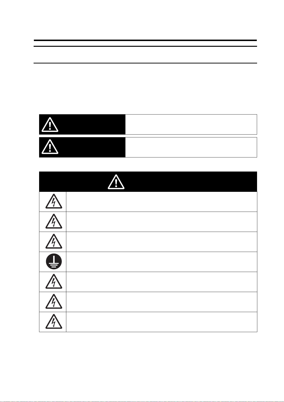
Indications and Meanings of Safety Information
In this user's manual, the following precautions and signal words are used to provide information to ensure the
safe use of the 3G3MX Inverter.
The information provided here is vital to safety. Strictly observe the precautions provided.
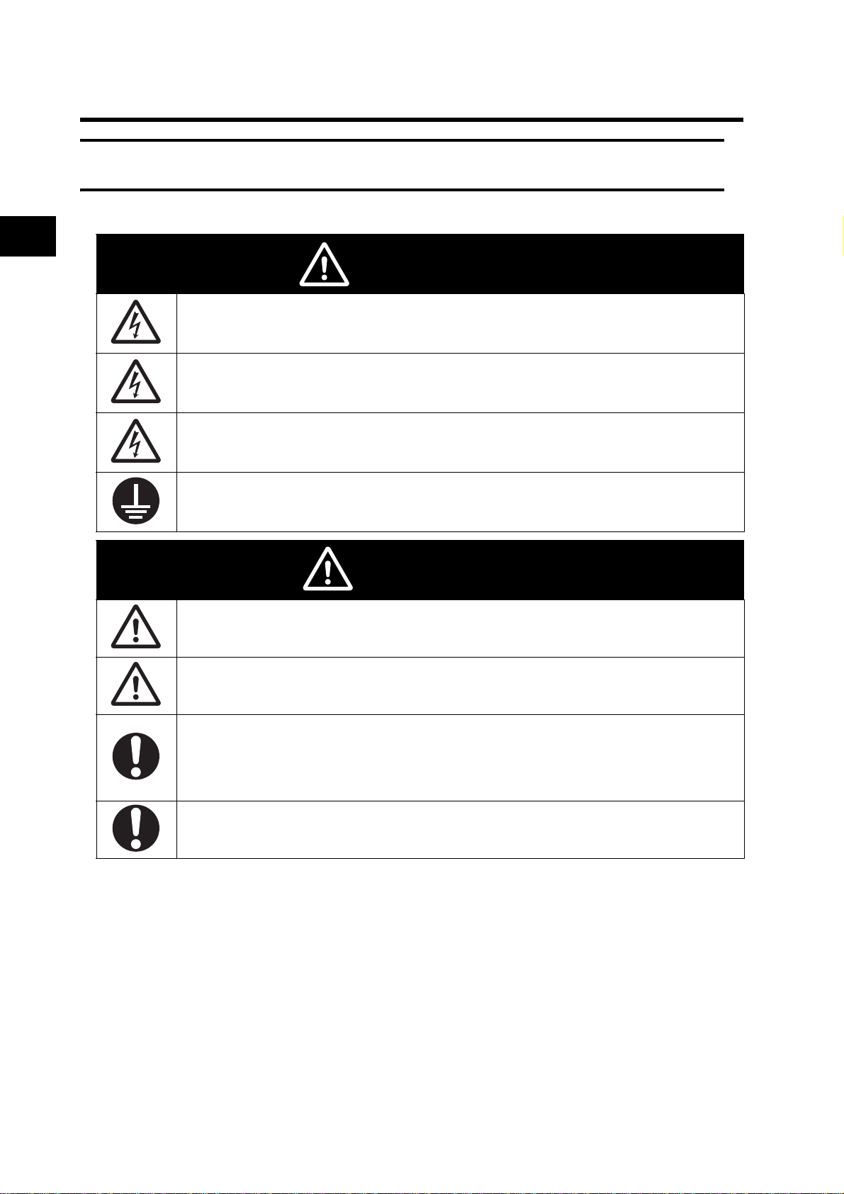
Meanings of Signal Words
Indicates an imminently hazardous situation which, if not avoided,
WARNING
CAUTION
Alert Symbols in this Document
is likely to result in serious injury or may result in death. Additionally
there may be severe property damage.
Indicates a potentially hazardous situation which, if not avoided,
may result in minor or moderate injury or in property damage.
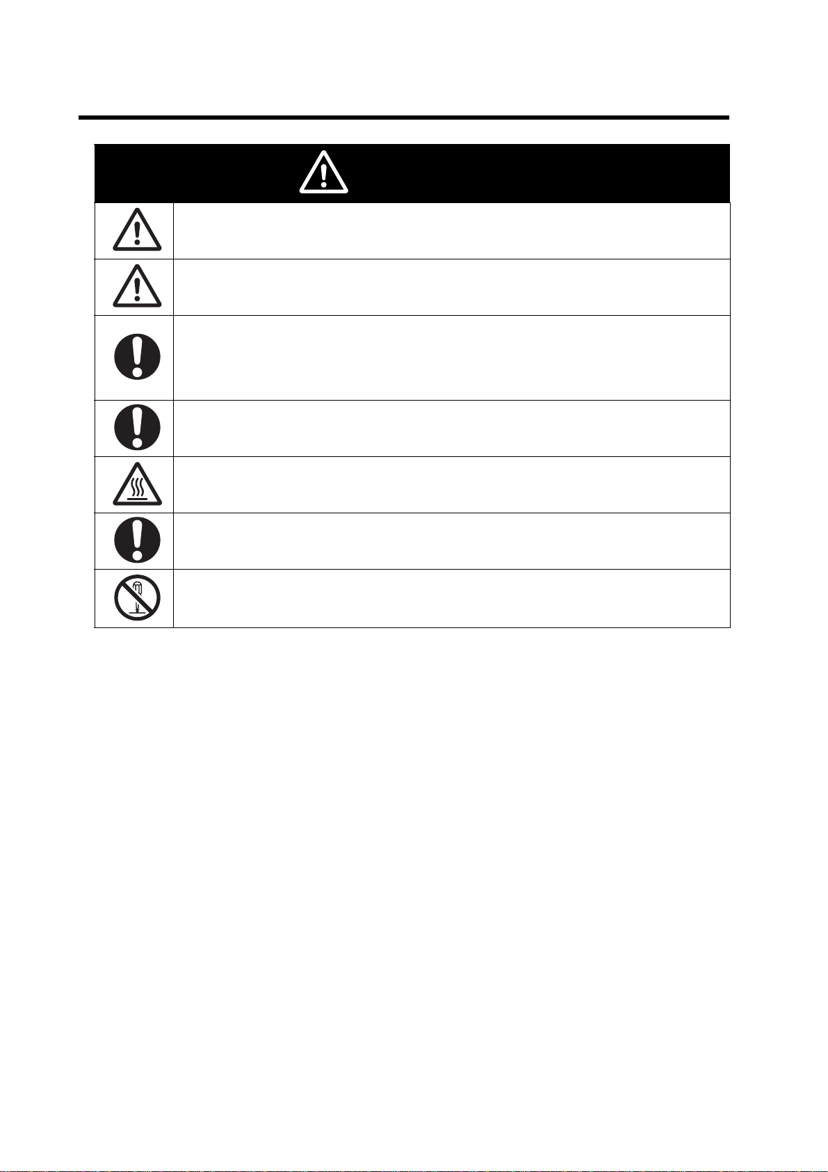
WARNING
Turn off the power supply and implement wiring correctly. Not doing so may result in a serious injury
due to an electric shock.
Wiring work must be carried out only by qualified personnel. Not doing so may result in a serious
injury due to an electric shock.
Do not put on or take off the Digital Operator•control circuit terminal block•terminal block cover
while the input power is being supplied. Doing so may result in a serious injury due to an electric
shock.
Be sure to ground the unit. Not doing so may result in a serious injury due to an electric shock or
fire.
(200-V class: type-D grounding, 400-V class: type-C grounding)
Do not remove the terminal block cover during the power supply and 5 minutes after the power
shutoff.
Doing so may result in a serious injury due to an electric shock.
Do not operate the Digital Operator or switches with wet hands. Doing so may result in a serious
injury due to an electric shock.
Do not change wiring, mode change switches, optional devices or replace cooling fans while power
is being supplied.
Doing so may result in a serious injury due to an electric shock.
5
Page 8
Safety Precautions
Do not connect resistors to the terminals (+1, P/+2, N/-) directly.
Doing so might result in a small-scale fire, heat generation or damage to the unit.
Install a stop motion device to ensure safety. Not doing so might result in a minor injury. (A holding
brake is not a stop motion device designed to ensure safety.)
Be sure to use a specified type of braking resistor/regenerative braking unit. In case of a braking
resistor, install a thermal relay that monitors the temperature of the resistor. Not doing so might
result in a moderate burn due to the heat generated in the braking resistor/regenerative braking
unit. Configure a sequence that enables the Inverter power to turn off when unusual overheating is
detected in the braking resistor/regenerative braking unit.
The Inverter has high voltage parts inside which, if short-circuited, might cause damage to itself or
other property. Place covers on the openings or take other precautions to make sure that no metal
objects such as cutting bits or lead wire scraps go inside when installing and wiring.
Do not touch the Inverter fins, braking resistors and the motor, which become too hot during the
power supply and for some time after the power shutoff. Doing so may result in a burn.
CAUTION
Take safety precautions such as setting up a molded-case circuit breaker (MCCB) that matches
the Inverter capacity on the power supply side. Not doing so might result in damage to property due
to the short circuit of the load.
Do not dismantle, repair or modify this product.
Doing so may result in an injury.
6
Page 9

Precautions for Safe Use
Precautions for Safe Use
Installation and Storage
Do not store or use the product in the following places.
•Locations subject to direct sunlight.
•Locations subject to ambient temperature exceeding the specifications.
•Locations subject to relative humidity exceeding the specifications.
•Locations subject to condensation due to severe temperature fluctuations.
•Locations subject to corrosive or flammable gases.
•Locations subject to exposure to combustibles.
•Locations subject to dust (especially iron dust) or salts.
•Locations subject to exposure to water, oil, or chemicals.
•Locations subject to shock or vibration.
Transporting, Installation, and Wiring
•Do not drop or apply strong impact on the product. Doing so may result in damaged parts or malfunction.
•Do not hold by the terminal cover, but hold by the fins during transportation.
•Do not connect an AC power supply voltage to the control input/output terminals. Doing so may result in
damage to the product.
•Be sure to tighten the screws on the terminal block securely.
Wiring work must be done after installing the unit body.
•Do not connect any load other than a three-phase inductive motor to the U, V, and W output terminals.
•Take sufficient shielding measures when using the product in the following locations. Not doing so may
result in damage to the product.
Locations subject to static electricity or other forms of noise.
Locations subject to strong magnetic fields.
Locations close to power lines.
Operation and Adjustment
•Be sure to confirm the permissible range of motors and machines before operation because the Inverter
speed can be changed easily from low to high.
•Provide a separate holding brake if necessary.
Maintenance and Inspection
•Be sure to confirm safety before conducting maintenance, inspection or parts replacement.
7
Page 10

Precautions for Correct Use
Precautions for Correct Use
Installation
•Mount the product vertically on a wall or on a DIN Rail (optional) with the product's longer sides upright.
The material of the wall has to be noninflammable such as a metal plate.
Main Circuit Power Supply
•Confirm that the rated input voltage of the Inverter is the same as AC power supply voltage.
Error Retry Function
•Do not come close to the machine when using the error retry function because the machine may abruptly
start when stopped by an alarm.
•Be sure to confirm the RUN signal is turned off before resetting the alarm because the machine may
abruptly start.
Operation Stop Command
•Provide a separate emergency stop switch because the STOP key on the Digital Operator is valid only when
function settings are performed.
•When checking a signal during the power supply and the voltage is erroneously applied to the control input
terminals, the motor may start abruptly. Be sure to confirm safety before checking a signal.
Product Disposal
•Comply with the local ordinance and regulations when disposing of the product.
8
Page 11
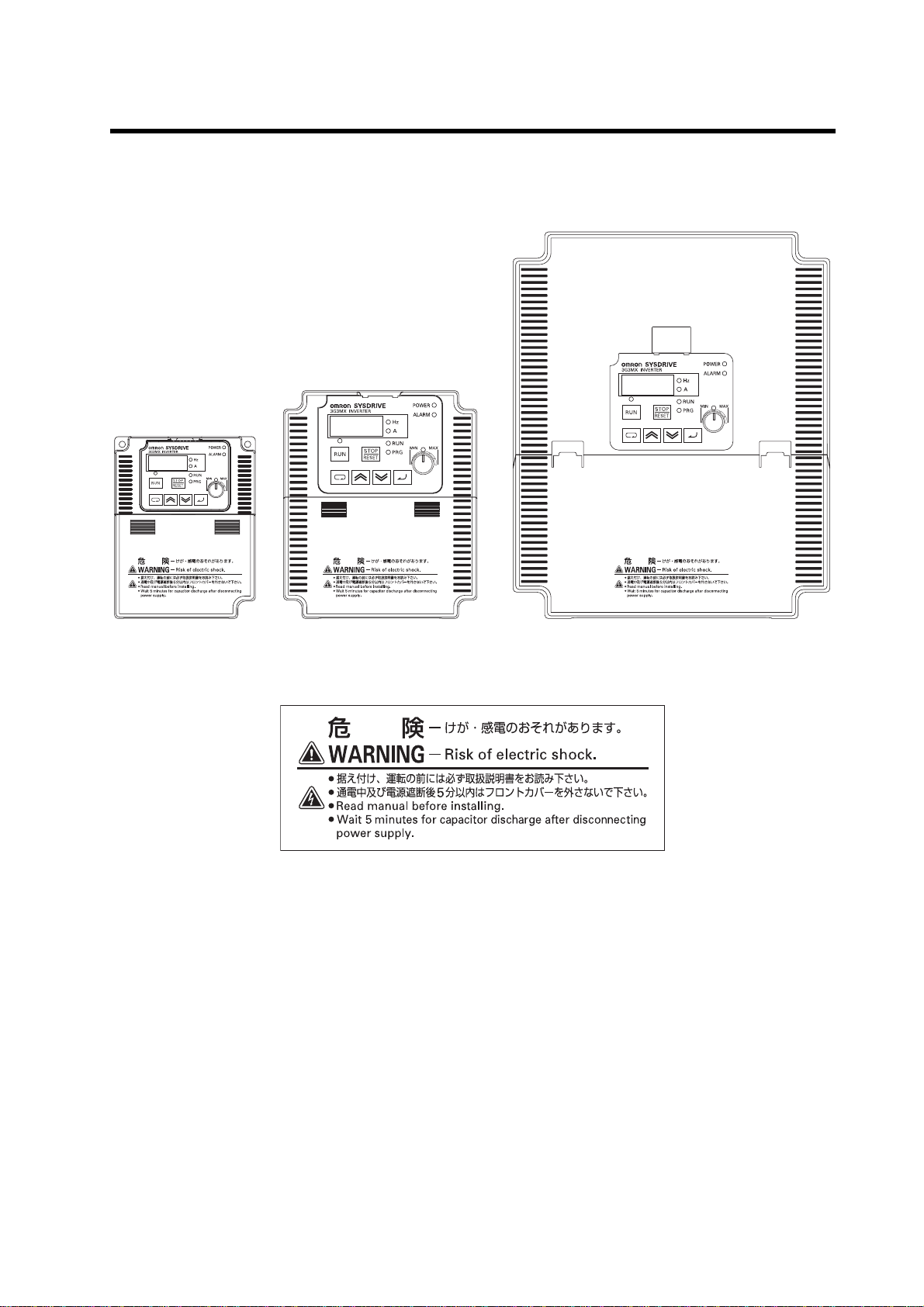
Warning Labels
Warning labels are located on the Inverter as shown in the following illustration.
Be sure to follow the instructions.
Precautions for Correct Use
Warning Description
9
Page 12
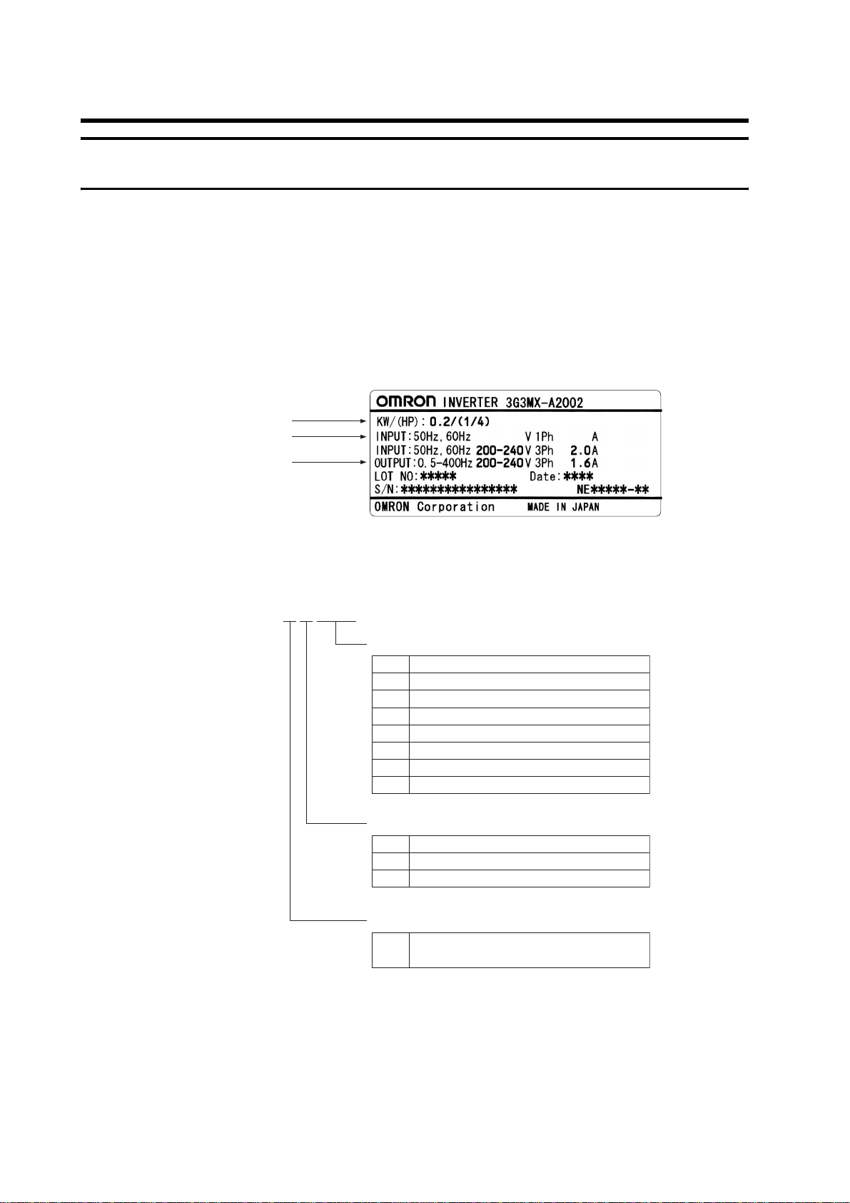
Checking Before Unpacking
Checking Before Unpacking
Checking the Product
On delivery, be sure to check that the delivered product is the Inverter 3G3MX model that you
ordered.
Should you find any problems with the product, immediately contact your nearest local sales
representative or OMRON sales office.
zChecking the Nameplate
Inverter model
Input specifications
Output specifications
zChecking the Model
3G3MX-A2002
Maximum applicable motor capacity
0.2 kW
002
0.4 kW
004
0.75 kW
007
1.5 kW
015
2.2 kW
022
3.7 kW
037
5.5 kW
055
7.5 kW
075
Voltage class
3-phase 200 V AC (200-V class)
2
1/3-phase 200 V AC (200-V class)
E
3-phase 400 V AC (400-V class)
4
Enclosure rating
Panel-mounting (IP10 min.) or closed
A
wall-mounting models
Checking the Accessories
Note that this manual is the only accessory included with the 3G3MX model.
Mounting screws and other necessary parts must be provided by the user.
10
Page 13

Revision History
Revision History
A manual revision code appears as a suffix to the catalog number located at the
lower left of the front and back covers.
Cat. No.
Revision code Revision date Changes and revision pages
01 December 2007 First printing
I559-E1-01
Revision code
11
Page 14

About This Manual
About This Manual
This User's Manual is compiled chapter by chapter for user's convenience as follows.
Understanding the following configuration ensures more effective use of the product.
Chapter 1 Overview Describes features and names of parts.
Provides external dimensions, installation dimensions, peripheral device
Chapter 2 Design
Chapter 3 Operation
Chapter 4 Functions Describes the functions of the Inverter.
Chapter 5
Chapter 6
Maintenance
Operations
Inspection and
Maintenance
design/selection instructions, and other information necessary for
design.
Describes names of parts, the Inverter's operations, including how to use
the keys on the Digital Operator, and the monitor function.
Describes the causes and their countermeasures if the Inverter fails,
including the solutions to possible troubles (troubleshooting).
Describes items for periodical inspection and/or maintenance for the
Inverter.
Overview
Chapter 7 Specifications
Appendix
Provides Inverter specifications, as well as the specifications and
dimensions of peripheral devices.
Describes the summarized parameter settings as a reference for users
who have used this Inverter and understood the functions.
12
Page 15

Contents
Introduction..............................................................................................1
Read and Understand this Manual..........................................................2
Safety Precautions ..................................................................................5
Precautions for Safe Use.........................................................................7
Precautions for Correct Use....................................................................8
Checking Before Unpacking....................................................................10
Revision History.......................................................................................11
About This Manual...................................................................................12
Chapter 1 Overview
1-1 Functions.................................................................................................1-1
1-2 Appearance and Names of Parts.............................................................1-3
Chapter 2 Design
2-1 Installation................................................................................................2-1
2-2 Removing and Mounting Each Part.........................................................2-5
2-3 Wiring.......................................................................................................2-10
Chapter 3 Operation
3-1 Test Run Procedure.................................................................................3-2
3-2 Test Run Operation .................................................................................3-3
3-3 Part Names and Descriptions of the Digital Operator..............................3-8
3-4 Operation Procedure (Example: Factory Default)....................................3-10
3-5 Keys.........................................................................................................3-16
3-6 Parameter Transition.......................................................................... .....3-17
3-7 Parameter List .......................... .... .... .... .... ..... .... .... .... .... ..... .... .... .... .... .....3-19
Chapter 4 Functions
4-1 Monitor Mode...........................................................................................4-1
4-2 Function Mode.........................................................................................4-5
Chapter 5 Maintenance Operations
5-1 Special Display List................... .... .... .... .... ..... .... .... .... .... ..........................5-1
5-2 Troubleshooting.......................................................................................5-5
Chapter 6 Inspection and Maintenance
6-1 Inspection and Maintenance....................................................................6-1
6-2 Storage....................................................................................................6-7
Chapter 7 Specifications
7-1 Standard Specification List................................................................. .....7-1
13
Page 16

Contents
7-2 Measurement Method of Output Voltage ................................................ 7-5
7-3 Connection Example............................................................................... 7-6
7-4 Dimensional Drawing .............................................................................. 7-8
7-5 Options.................................................................................................... 7-14
Appendix
Appendix-1 Parameter List .........................................................................App-1
Appendix-2 Product Life Curve...................................................................App-17
Index
14
Page 17

Chapter 1
Overview
1-1 Functions.......................................................... 1-1
1-2 Appearance and Names of Parts.................... 1-3
Page 18

1-1 Functions
1Overview
1
1-1 Functions
3G3MX Inverter Models
Overview
3-phase 200 V AC
3-phase 400 V AC
Rated voltage Enclosure rating Max. applicable motor capacity Model
0.2 kW 3G3MX-A2002
0.4 kW 3G3MX-A2004
0.75 kW 3G3MX-A2007
1.5 Kw 3G3MX-A2015
2.2 kW 3G3MX-A2022
3.7 kW 3G3MX-A2037
5.5 kW 3G3MX-A2055
7.5 kW 3G3MX-A2075
0.4 kW 3G3MX-A4004
IP20
(Complies with
JEM1030)
0.75 kW 3G3MX-A4007
1.5 kW 3G3MX-A4015
2.2 kW 3G3MX-A4022
3.7 kW 3G3MX-A4037
5.5 kW 3G3MX-A4055
7.5 kW 3G3MX-A4075
0.2 kW 3G3MX-AE002
0.4 kW 3G3MX-AE004
1/3-phase 200 V AC
0.75 kW 3G3MX-AE007
1.5 kW 3G3MX-AE015
2.2 kW 3G3MX-AE022
International Standards Models (EC Directives and UL/cUL Standards)
The 3G3MX Inverter meets the EC Directives and UL/cUL standard requirements for worldwide
use.
Classification Applicable standard
EC Directives
UL/cUL Standards UL508C
EMC Directive EN61800-3: 2004
Low-voltage Directive EN61800-5-1: 2003
1-1
Page 19

1-1 Functions
Easy-to-use General-purpose Inverter with Vector Control Functions
Advanced Functions
High Starting Torque
With its vector control, the 3G3MX Series has achieved high starting torque in excess of 200% at 1
Hz.
Trip Suppression
This Inverter features two trip suppression functions: "Overcurrent suppression function" to
suppress overcurrent trip during acceleration, and "Overvoltage LAD stop function" to suppress
overvoltage trip during deceleration. Therefore, the 3G3MX Series provides tough operational
capabilities regardless of the severe time setting of acceleration and deceleration.
Equipped with Communication Function
ModBus-RTU communication allows you to perform network operation at low cost.
Easy Operation
Adoption of Removable Control Circuit Terminal Block
Adoption of a removable control circuit terminal block substantially reduces onerous task of wiring
during the maintenance work.
Removable Digital Operator
The 3G3MX Series features a removable Digital Operator as a standard. By removing the Digital
Operator and connecting with the dedicated cable, you can operate the Inverter at hand and mount
it on the surface of the control panel.
1
Overview
Side-by-side Mounting
Side-by-side mounting contributes to space saving.
Built-in Braking Circuit
All models are equipped with a braking transistor, which is capable of handling applications with
rapid acceleration and stop.
1-2
Page 20
1-2 Appearance and Names of Parts
1
1-2 Appearance and Names of Parts
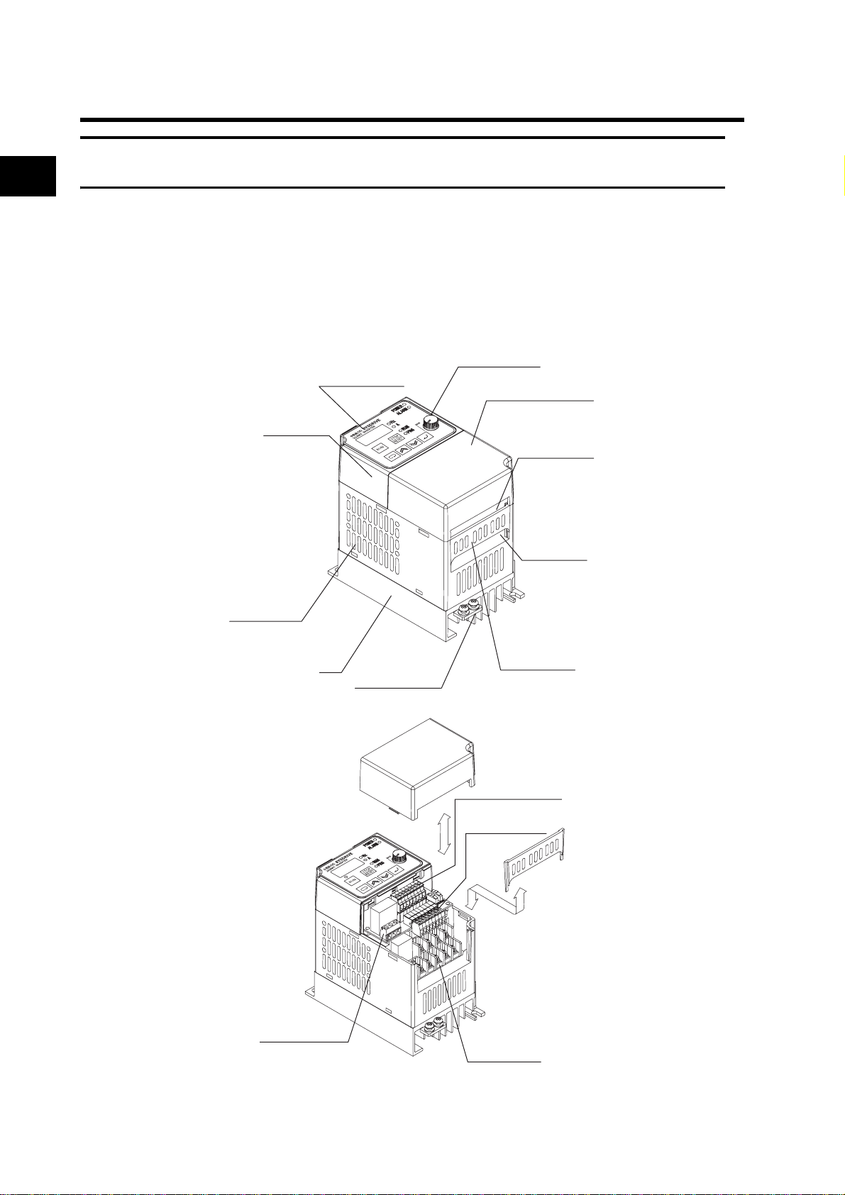
3G3MX-A2002 to A2007, 3G3MX-AE002 to AE004
Overview
You can open and close the terminal block cover by hand, without using any tool. When the terminal
block cover is removed as illustrated below, you can operate the mode selector and perform wiring
to the control circuit terminal block, the main circuit terminal block, and the relay output terminal
block.
FREQ adjuster
Digital Operator
Terminal block cover
Front cover
Control circuit
wiring hole
Main circuit
wiring hole
Main housing
Relay output
terminal block
Fin
Ground terminal
Bottom cover
Control circuit
terminal block A
Control circuit
terminal block B
Main circuit
terminal block
1-3
Page 21
1-2 Appearance and Names of Parts
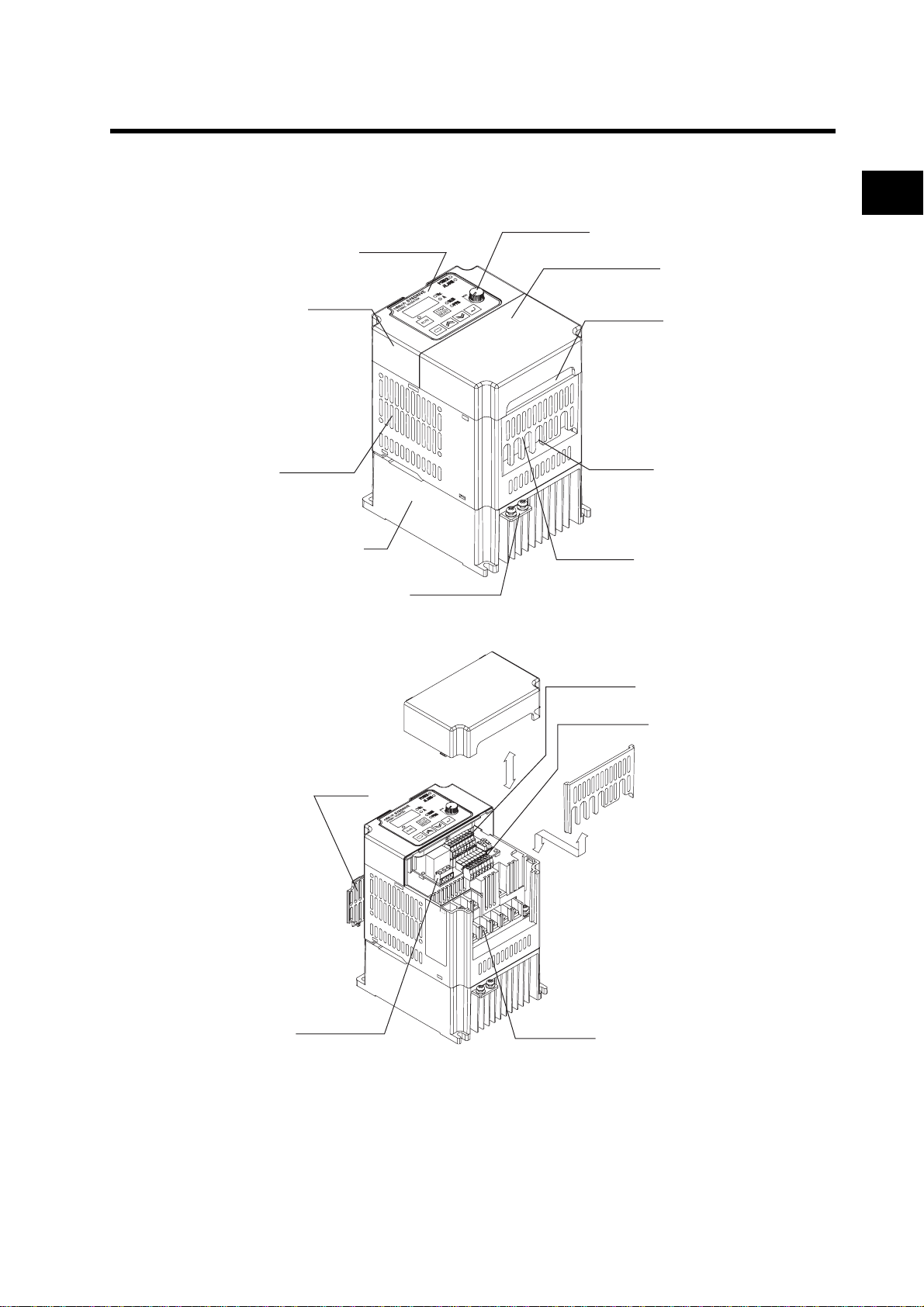
3G3MX-A2015 to A2037, 3G3MX-A4004 to A4037, 3G3MX-AE007 to AE022
Front cover
Main housing
Digital Operator
Fin
Ground terminal
FREQ adjuster
Terminal block cover
Bottom cover
1
Overview
Control circuit
wiring hole
Main circuit
wiring hole
Control circuit
terminal block A
Control circuit
terminal block B
Top cover
Relay output
terminal block
Main circuit
terminal block
Note: The top cover is intended for maintenance use only. Do not remove the top cover.
1-4
Page 22
1-2 Appearance and Names of Parts
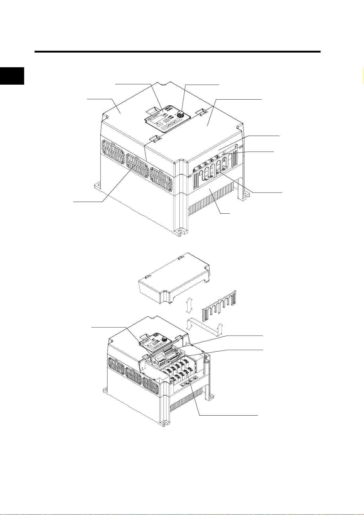
3G3MX-A2055 to A2075, 3G3MX-A4055 to A4075
1
Overview
Front cover
Main housing
Digital Operator
FREQ adjuster
Terminal block cover
Control circuit
wiring hole
Main circuit
wiring hole
Bottom cover
Fin
1-5
Relay output
terminal block
Control circuit
terminal block A
Control circuit
terminal block B
Main circuit terminal block
Page 23
1-2 Appearance and Names of Parts
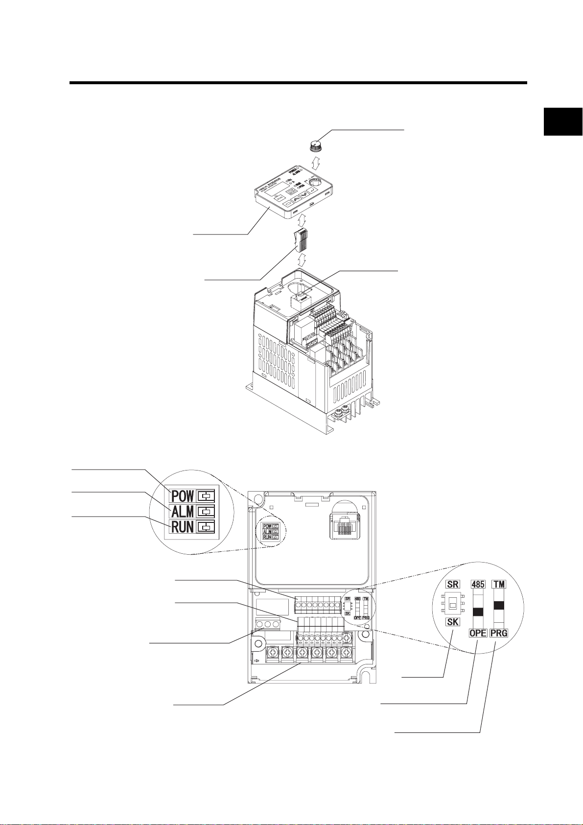
Names of Parts (When the Digital Operator is Removed)
Digital Operator
Digital Operator
connection plug
FREQ adjuster knob
Communications
connector
1
Overview
POWER LED indicator
ALARM LED indicator
RUN (RUN LED indicator)
Relay output terminals
Control circuit
terminal block A
Control circuit
terminal block B
Main circuit
terminal block
Input logic
selector
RS-485 communication/
Operator selector
Frequency reference/
Run command selector
1-6
Page 24

Page 25

Chapter 2
Design
2-1 Installation ........................................................2-1
2-2 Removing and Mounting Each Part................ 2-5
2-3 Wiring................................................................ 2-10
Page 26
2
Design
2-1 Installation
2Design
2-1 Installation
WARNING
Turn off the power supply and implement wiring correctly. Not doing so may result in a serious injury
due to an electric shock.
Wiring work must be carried out only by qualified personnel. Not doing so may result in a serious
injury due to an electric shock.
Do not put on or take off the Digital Operator•control circuit terminal block•terminal block cover while
the input power is being supplied. Doing so may result in a serious injury due to an electric shock.
Be sure to ground the unit. Not doing so may result in a serious injury due to an electric shock or fire.
(200-V class: type-D grounding, 400-V class: type-C grounding)
CAUTION
Do not connect resistors to the terminals (+1, P/+2, N/-) directly.
Doing so might result in a small-scale fire, heat generation or damage to the unit.
Install a stop motion device to ensure safety. Not doing so might result in a minor injury. (A holding
brake is not a stop motion device designed to ensure safety.)
Be sure to use a specified type of braking resistor/regenerative braking unit. In case of a braking
resistor, install a thermal relay that monitors the temperature of the resistor. Not doing so might result
in a moderate burn due to the heat generated in the braking resistor/regenerative braking unit.
Configure a sequence that enables the Inverter power to turn off when unusual overheating is
detected in the braking resistor/regenerative braking unit.
The Inverter has high voltage parts inside which, if short-circuited, might cause damage to itself or
other property. Place covers on the openings or take other precautions to make sure that no metal
objects such as cutting bits or lead wire scraps go inside when installing and wiring.
2-1
Page 27

2-1 Installation
Safety Information
Installation and Storage
Do not store or use the product in the following places.
•Locations subject to direct sunlight.
•Locations subject to ambient temperature exceeding the specifications.
•Locations subject to relative humidity exceeding the specifications.
•Locations subject to condensation due to severe temperature fluctuations.
•Locations subject to corrosive or flammable gases.
•Locations subject to exposure to combustibles.
•Locations subject to dust (especially iron dust) or salts.
•Locations subject to exposure to water, oil, or chemicals.
•Locations subject to shock or vibration.
Transporting, Installation, and Wiring
•Do not drop or apply strong impact on the product. Doing so may result in damaged parts or malfunction.
•Do not hold by the terminal cover, but hold by the fins during transportation.
•Do not connect an AC power supply voltage to the control input/output terminals. Doing so may result in
damage to the product.
•Be sure to tighten the screws on the terminal block securely.
Wiring work must be done after installing the unit body.
•Do not connect any load other than a three-phase inductive motor to the U, V, and W output terminals.
•Take sufficient shielding measures when using the product in the following locations. Not doing so may
result in damage to the product.
Locations subject to static electricity or other forms of noise.
Locations subject to strong magnetic fields.
Locations close to power lines.
2
Design
2-2
Page 28
2-1 Installation
.
Precautions for Use
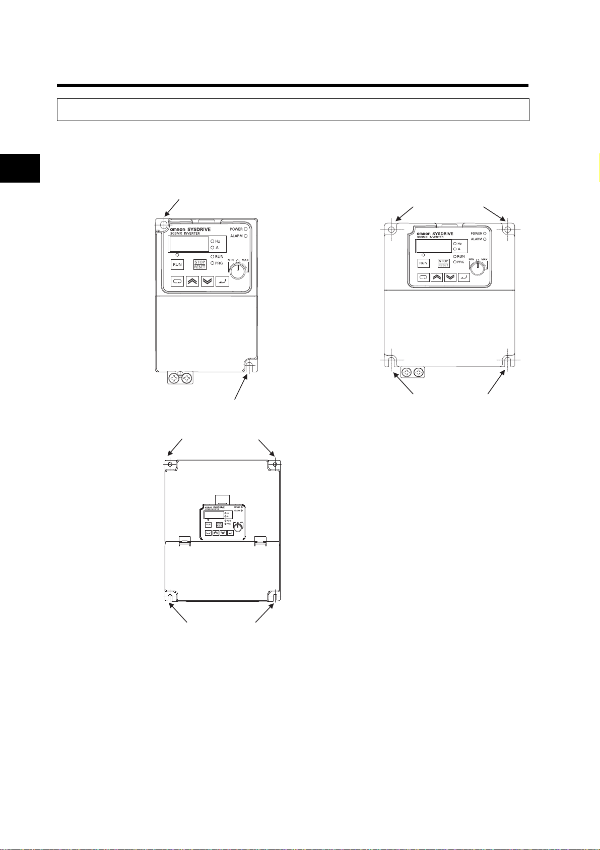
Installation
•Install the Inverter vertically on the wall or DIN tracks (optional).
2
The material of the wall has to be noninflammable such as a metal plate.
Design
Model
3G3MX-A2002
Screw size for
installation: M5
A2004
A2007
AE002
AE004
Model
3G3MX-A2055
-A2075
-A4055
-A4075
Position for installing a screw
Position for installing a screw
Positions for
installing screws
Model
3G3MX-A2015
Screw size for
installation: M5
A2022
A2037
A4004
A4007
A4015
A4022
A4037
AE007
AE015
AE022
Positions for installing screws
Positions for installing screws
Screw size for
installation: M6
Positions for
installing screws
Main Circuit Power Supply
•Confirm that the rated input voltage of the Inverter matches the AC power supply voltage.
2-3
Page 29
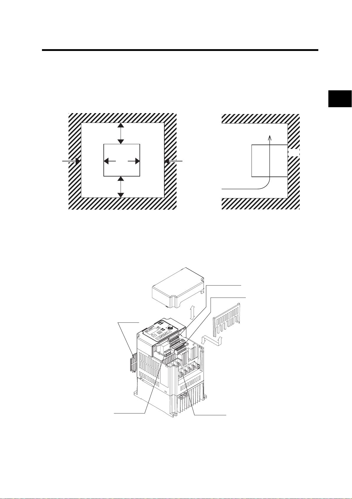
Installation Environment
•Increased ambient temperatures will shorten the life of the Inverter.
•Keep the Inverter away from heating elements (such as a braking resistor, DC reactor, etc.).
If the Inverter is installed in a control panel, keep the ambient temperature within the range of the
specifications, taking dimensions and ventilation into consideration.
10 cm min.
5 cm min. 5 cm min.
10 cm min.
Airflow
2-1 Installation
2
Design
Wall
•If the ambient temperature is from 40°C to 50°C, the carrier frequency should be reduced and the Inverter
capacity should be increased.
•Before installing the Inverter, place a cover over all the ventilation openings to shield them from foreign
objects.
After completing the installation process, be sure to remove the covers from the Inverter before operation.
Control circuit
terminal block A
Control circuit
terminal block B
Top cover
Relay output
terminal block
Main circuit
terminal block
2-4
Page 30
2-2 Removing and Mounting Each Part
2-2 Removing and Mounting Each Part
2
Design
Removing and Mounting the Terminal Block Cover
3G3MX-A2002 to A2037, 3G3MX-A4004 to A4037, 3G3MX-AE002 to AE022
(1) Removing the Terminal Block Cover
Press the one side (1) of tab A on the terminal block cover, and use the opposite side of tab A as a
supporting point to disconnect tab B on the same side of the pressed tab A.
Then, press the opposite side of tab A and disconnect the other tab B.
Supporting point
(1)
Tab B
2-5
Connection to the
terminal block cover
Tab A
Page 31

2-2 Removing and Mounting Each Part
(2) Mounting the Terminal Cover
Push down both sides of A and B simultaneously from the upper side of the terminal cover until it
clicks into place.
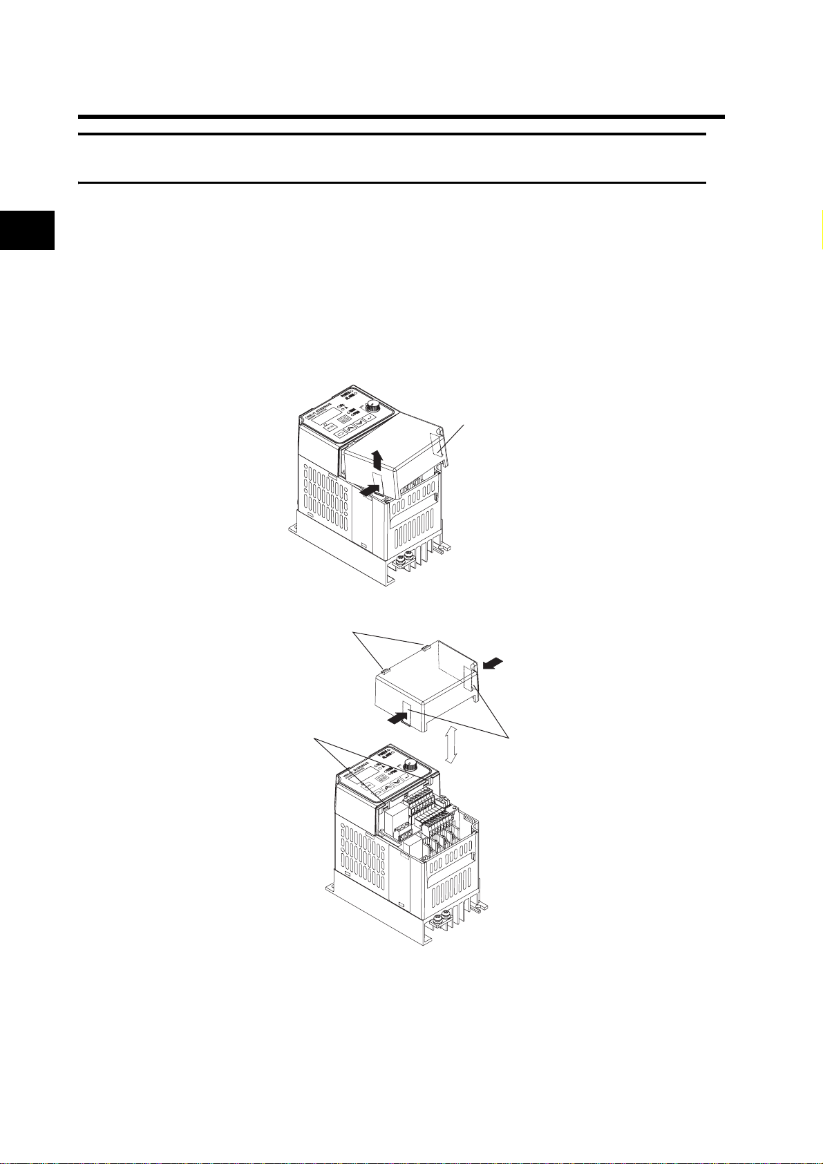
3G3MX-A2055 to A2075, 3G3MX-A4055 to A4075
(1) Removing the Terminal Block Cover
•Press the two A tabs on the terminal block cover toward the direction of the arrow in the figure below,
and unlock the front cover to disconnect.
•
Use the B tabs on the terminal block cover and the fitting part with the main unit hou sing as supportin g
points, and lift up the terminal block cover.
2
Design
2-6
Page 32

2
Design
2-2 Removing and Mounting Each Part
(2) Mounting the Terminal Block Cover
Fit the B tabs on the terminal block cover into the main unit housing, and push down the cover from
the upper side until the two A tabs click into place.
Removing and Mounting the Digital Operator
Removing the Digital Operator
Pressing the upper tab on the Digital Operator, pull it up to the Inverter's front (upper direction in the
figure below).
*Supplemental Information
When using the communications connector, remove the Digital Operator connection plug. It can be
removed by pulling it up to the Inverter's front (upper direction in the figure below).
2-7
Page 33

Mounting the Digital Operator
Place the bottom of the Digital Operator into the open space in the front cover, and push down the
upper side of the Digital Operator.
2-2 Removing and Mounting Each Part
*Supplemental Information
Before mounting the Digital Operator, be sure to mount the Digital Operator connection plug. To
mount the Digital Operator connection plug, push its tab into the communication connector until it
clicks into place.
Removing and Mounting the Control Circuit Terminal Blocks
Removing the Control Circuit Terminal Blocks
Step (1)
Pull up control circuit terminal block A (Terminals SC, S1 to S6) off the Inverter's front (upper direction in the figure below) to remove.
Step (2)
Loosen the screws on the both sides of the control circuit terminal block B (Terminals FS, FV, FI,
FC, AM, PC, P2, P1) and pull it up toward the Inverter's bottom (right lower direction in the figure
below) to remove.
Control circuit terminal block A
2
Design
Control circuit terminal block B
2-8
Page 34

2-2 Removing and Mounting Each Part
Mounting the Control Circuit Terminal Blocks
Step (1)
Push control circuit terminal block A (Terminals SC, S1 to S6) down securely on the Inverter's front
(upper direction in the figure on the previous page).
2
Step (2)
Push control circuit terminal block B (Terminals FS, FV, FI, FC, AM, PC, P2, P1) down securely from
the Inverter's bottom (right lower direction in the figure on the previous page). Furthermore, securely
tighten the screws on the both sides of the terminal block. Loosened screws may result in the terminal block falling off.
Design
Note: To remove/mount the control circuit terminal blocks, you need a screwdriver with a tip size of
+No.0, and a shaft diameter of 2.4 mm or less.
2-9
Page 35

2-3 Wiring
2-3 Wiring
Wiring to the Power Supply and Motor
Open the terminal block cover and wire the main circuit terminal blocks.
3G3MX-A2002 to A2007, 3G3MX-AE002 to AE004
Frame format of the main circuit terminal block
Main circuit
terminal block
Short-circuit bar
R/L1
(L1)
S/L2
(L2)
RB
T/L3
(N/L3)
* Terminal symbols for 3G3MX-AE are indicated in parentheses ( ).
3G3MX-A2015 to A2037, 3G3MX-A4004 to A4037, 3G3MX-AE007 to AE022
Frame format of the main circuit terminal block
P/+2 N/-
+1
U/T1 V/T2 W/T3
Upper
Lower
2
Design
Short-circuit bar
RB
Upper
Main circuit
terminal block
+1
R/L1
(L1)
P/+2 N/-
S/L2
T/L3
(L2)
(N/L3)
U/T1 V/T2 W/T3
* Terminal symbols for 3G3MX-AE are indicated in parentheses ( ).
Lower
2-10
Page 36

2-3 Wiring
3G3MX-A2055 to A2075, 3G3MX-A4055 to A4075
Frame format of the main circuit terminal block
2
Design
Standard Connection Diagram
1/3-phase 200 V AC *2
3-phase 200 V AC
3-phase 400 V AC
Frequency
reference
(1 to 2 kΩ)
+1 P/+2 N/- RB
Main circuit
terminal block
DC reactor
(optional)
+1 P/+2
R/L1 (L1) *1
S/L2 (L2)
T/L3 (N/L3)
PSC
Multi-function input 1
Multi-function input 2
Multi-function input 3
Multi-function input 4
Multi-function input 5
Multi-function input 6
Sequence input common
Frequency reference power supply (20 mA at +12 V)
Frequency reference input (voltage)
Frequency reference common
Frequency reference input (current)
(4 to 20 mA)
S1
S2
S3
S4
S5
S6
SC
FS
FV
FC
FI
S/L2 T/L3 U/T1 V/T2 W/T3R/L1
Short-circuit bar
Braking resistor
(optional)
RBN/–
U/T1
V/T2
W/T3
MB
MA
MC
P1 Multi-function output 1
P2PCMulti-function output 2
AM Analog monitor output
Upper
Lower
M
Relay output *3
Common
Multi-function output common
2-11
*1. Terminal symbols for 3G3MX-AE are indicated in parentheses ( ).
*2. Connect a single-phase 200-V AC input to terminals L1 and N/L3.
*3. By factory default, MA is set to NC contact, and MB to NO contact in the relay output (MA, MB) selection (C036).
Page 37

Connecting to the Power Supply and Motor
R/L1
S/L2
T/L3
U/ T1 V/T2 W/ T3
(N/L3)
Inverter
(L1)
(L2)
2-3 Wiring
2
Design
Power supply
* Terminal symbols for 3G3MX-AE are indicated in parentheses ( ).
•Do not connect the power supply other than to R/L1, S/L2, or T/L3.
•Do not remove the short-circuit bar between P/+2 and +1, except when a DC reactor is connected.
Note 1: Install an earth leakage breaker on the power supply input side.
(Select an earth leakage breaker having a larger high-frequency sensed current and avoid
unnecessary operations.)
If the wiring between the Inverter and the motor is too long (longer than 10 m), the thermal
relay may malfunction due to harmonics. Install an AC reactor on the Inverter output side,
or use a current sensor instead of the thermal relay.
Note 2: Connect securely to the ground as specified (type-D grounding for 200-V class, and type-C
grounding for 400-V class). Do not share the grounding electrode with other strong electrical
devices.
Motor
Example of incorrect grounding Example of correct grounding
Inverter
Inverter
Inverter
Inverter
Ground bolt
Inverter
Inverter
2-12
Page 38

2
Design
2-3 Wiring
Wiring the Control Circuit Terminals and Relay Output Terminals
Relay output
terminal block
Wiring Example of the Control Circuit Terminal Block (Sink Logic)
2-step acceleration/
deceleration
Reset
Input common
SC S6 S5 S4 S3 S2 S1 PSC
FS FC AM PC P2 P1
FV FI
Multi-step speed
reference 2
Relay
MB
MA MC
Relay output
Reverse RUN
command
Multi-step speed
reference 1
Forward RUN
SC S6 S5 S4 S3 S2 S1 PSC
FS FC AM PC P1P2
command
External power supply
terminal for input signal
Control circuit terminal block A
FI
FV
Control circuit terminal block B
At sink logic (NPN): External power
supply input
At source logic (PNP): Power
supply output
Note: By factory default, the input logic
of the multi-function input terminal
circuit is set to the sink logic.
Frequency
meter
2-13
2
3 1
Variable resistor
Frequency reference
(1 to 2 kΩ) 1k
Signal during RUN
27 V DC
50 mA max.
RYRY
Frequency arrival signal
Note 1: When connecting a relay to the multi-function output terminal, install a surge-absorbing
diode in parallel with the relay. The output circuit can break down due to surge voltage when
the relay is switched on/off.
Note 2: For the signal line, use a twisted shield wire and apply the shield coating as illustrated on
the next page. Keep the length to 20 m or less.
Page 39

Perform insulating
treatment.
2-3 Wiring
2
Ground connection is
not required.
Connect to the ground terminal of the Inverter.
Note 3: Separate the wiring from the power cable of the main circuit and from the wiring on the relay
control circuit. (More than 10 cm apart.)
Selecting the Sequence Input Method (Sink/Source Logic)
Sink logicSource logic
Inverter's internal circuitry
When interface power supply is used
24 V DC
PSC
S1
S6
COM
SC
When external power supply is used
24 V DC
COM
Design
24 V DC
PSC
S1
S6
SC
PLC etc.
COM
Inverter
PSC
InverterPLC etc.
P24
S1
S6
SC
24 V DC
PLC etc.
\
COM
24 V DC
PLC etc.
Inverter
24 V DC
P24
PSC
S1
S6
PSC
SC
Inverter
2-14
Page 40

2-3 Wiring
Wiring the Main Circuit Terminals
Connecting the Main Circuit Terminals
2
Design
Motor output
(kW)
Applicable Inverter model
0.2 3G3MX-A2002 1.25 mm
3G3MX-A2004
0.4
3G3MX-A4004 3 A
3G3MX-A2007 2.0 mm
0.75
3G3MX-A4007 1.25 mm
3G3MX-A2015 2.0 mm
1.5
3G3MX-A4015 2.0 mm
3G3MX-A2022 2.0 mm
2.2
3G3MX-A4022 2.0 mm
3G3MX-A2037 3.5 mm
3.7
3G3MX-A4037 2.0 mm
3G3MX-A2055 5.5 mm
5.5
3G3MX-A4055 2.0 mm
3G3MX-A2075 8.0 mm
7.5
3G3MX-A4075 3.5 mm
0.2 3G3MX-AE002 1.25 mm
0.4 3G3MX-AE004 1.25 mm
0.75 3G3MX-AE007 2.0 mm
1.5 3G3MX-AE015 2.0 mm
2.2 3G3MX-AE022 2.0 mm
Wiring Applicable device
Power cable
2
1.25 mm
2
2
2
2
2
2
2
2
2
2
2
2
2
2
2
2
2
2
Earth leakage breaker
(ELB)
(5 A) 10 A
(5 A)
(10 A) 15 A
(5 A) 6 A
(15 A) 15 A
(10 A) 10 A
(20 A) 20 A
(10 A) 10 A
(30 A) 30 A
(15 A) 15 A
(50 A) 40 A
(30 A) 20 A
(60 A) 50 A
(30 A) 25 A
(5 A)
(5 A)
(10 A)
(15 A)
(20 A)
Fuse size
(class J)
Rated 600 V
10 A
• For the main circuit terminals, always use insulated electrical wires with a rated voltage of 600 V and a rated
temperature of 80°C or higher.
• Use the crimp-type terminal with an insulating sleeve to connect to the terminals.
• Up to two wires can be connected to one terminal.
• To prevent possible voltage drops, increase the wire size in accordance with the cable length.
2
• To connect the 100-V or 200-V model to the relay output terminal, use a wire of 0.75 mm
• To connect seven wires or more to the control circuit terminal block, use a shield wire of 0.5 mm
.
2
or less.
• Strip the signal line by 5 to 6 mm, and connect the exposed wire. (In the case of stra nded wires, make sure that
the wires are not unraveled.)
• Make sure that the maximum outside coating diameter of the signal line is 2.0 mm or less (except for the alarm
signal line). (For the mark tube mounted cable and multi-core cable, keep both the mark tube and the sheathstripped length 40 mm or more from the connecting end. A thick line may prevent proper closing of the cover
of the terminal block.)
• To meet the UL standards, always insert a UL-standard fuse (J type) on the power supply side.
• Use a ground wire with a larger diameter than that of the power cable shown above.
2-15
Page 41

2-3 Wiring
Choose the sensitivity current of the earth leakage breaker (ELB), depending on the total distance (L) between
the Inverter and the power supply, and the Inverter and the motor.
L
100 m max. 30
300 m max. 100
800 m max. 200
Sensitivity
current (mA)
Terminal arrangement
Main circuit terminal block Type Screw size D (mm)
RB
R/L1 S/L2
+1 P/+2
T/L3
N/-
R/L1 S/L2 T/L3 U/T1
+1
U/T1 V/T2
Guide of leakage current: If a CV wire is used and routed through a metal pipe,
the leakage current is 30 mA/km.
Due to the higher specific inductive capacity of the H-IV wire, the leakage current
increases about eight times. Use a wire with a sensitivity current one-level higher.
The leakage current mentioned here is the effective value of the fundamental wave,
and high-frequency currents are excluded.
Ground T erminal Block
P/+2 N/-
A2002 to A2007
AE002 to AE004
(*1)
M3.5 7.6
W/T3
7.6 (10)
A2015 to A2037
A4004 to A4037
AE007 to AE022
(*1)
M4 10
V/T2
RB
W/T3
2
Design
Main Circuit Terminal Block
R/L1
*1. For 3G3MX-AE, L1, L2, N/L3 are indicated instead of R/L1, S/L2, T/L3 respectively.
S/L2 T/L3 U/T1 V/T2
+1
P/+2
Type
Main circuit M3.5 7.6 M4 10 M5 13
Control circuit M2 M2 M2
Relay M2.5 M2.5 M2.5
Ground M4 M4 M6
N/-
RB
A2002 to A2007
AE002 to AE004
Screw size D (mm) Screw size D (mm) Screw size D (mm)
W/T3
A2055 to A2075
A4055 to A4075
A2015 to A2037
A4004 to A4037
AE007 to AE022
M5 13
A2055 to A2075
A4055 to A4075
2-16
Page 42

2-3 Wiring
Screw Tightening Torque
2
Design
Screw Tightening torque
M2 0.2 N•m (max. 0.25 N•m)
M2.5 0.5 N•m (max. 0.6 N•m)
M3.5 0.8 N•m (max. 0.9 N•m)
Control Circuit Terminal Block
SC S6S5 S4 S3 S2 S1
FSFV FI FCAM PC P2 P1
Relay output terminal block
M4 1.2 N•m (max. 1.3 N•m)
M5 2.0 N•m (max. 2.6 N•m)
MB MA MC
Explanation of the Main Circuit Terminal Connection
Terminal
symbol
R/L1,
S/L2,
T/L3 *
U/T1,
V/T2,
W/T3
+1,
P/+2
Terminal name Function Connection example
Main power supply
input terminal
Inverter output
terminal
External DC
reactor terminal
Connect the input power supply.
Connect to the motor.
Normally connected by the short-circuit
bar. Remove the short-circuit bar between
+1 and P/+2 when a DC reactor is
connected.
PSC
Motor
ELB
External braking
P/+2
RB
P/+2, N/-
resistor
connection
terminal
Regenerative
braking unit
connection
terminal
Ground terminal
Connect the optional braking resistor. (If a
braking torque is required)
Connect optional regenerative braking
units.
(If a braking torque is required)
(if insufficient with only the built-in
braking circuit)
Ground (Connect to the ground to
prevent electric shock and reduce noise.)
Power supply
Do not remove the short-circuit bar
between +1 and P/+2 when a DC
reactor is not connected.
* Terminal symbols for 3G3MX-AE are indicated as L1, L2, N/L3 instead of R/L1, S/L2, T/L3 respectively.
Main Circuit Connection Diagram
Molded case
circuit-breaker
(MCCB)
Power supply
MC
AC reactor
noise filter
Fuse
* Terminal symbols for 3G3MX-AE are indicated as L1, L2, N/L3 instead of R/L1, S/L2, T/L3
respectively.
Regenerative braking unit
P/+2 N/-
R/L1
S/L2
T/L3 *
Inverter
3G3MX
U/T1
V/T2
W/T3
M
2-17
Page 43

Wiring the Main Circuit Terminals (Input Side)
Installing a Molded-case Circuit Breaker (MCCB)
•Always connect the Inverter and power supply via a molded-case circuit breaker (MCCB) to protect
the Inverter from damage that may result from short-circuiting.
•Always connect the power input terminals (R/L1, S/L2, and T/L3) and power supply via an MCCB,
according to the Inverter capacity.
•Install one MCCB per Inverter.
•Choose an appropriate MCCB capacity according to the fuse size on page 2-15.
•When choosing an MCCB's time characteristics, be sure to consider the Inverter's overload
protection (1 minute at 150% of the rated output current).
•By programming the sequence as illustrated below, you can turn off the power via the relay outputs
(MA, MB, and MC) for the 3G3MX Series.
Molded case
circuit-breaker
(MCCB)
Power supply
MC
OFF
X1
X1
X2
ON
X1
X2
DC (24 V) relay
R/L1 (L1)
S/L2 (L2)
T/L3 (N/L3)
MA
(30 V DC, 50 mA max.)
MC
Inverter
3G3MX
2-3 Wiring
2
Design
* Terminal symbols for 3G3MX-AE are indicated in parentheses ( ).
Installing a Ground Fault Interrupter
•The Inverter's output uses high-speed switching, and so generates high-frequency current
leakage. (Generally, if the power cable is 1 m, the leakage current is approx. 100 mA per Inverter,
and approx. 5 mA is added per additional meter.)
•At the power supply input part, install a special-purpose ground fault interrupter for Inverters that
exclude high-frequency leakage current and detect only the leakage current within a frequency
range that is hazardous to humans. (Choose a ground fault interrupter with a sensitivity current of
at least 10 mA per Inverter.)
•Alternatively, use a general ground fault interrupter with a sensitivity current of 200 mA or more per
Inverter, and with an operating time of 0.1 s or more.
Installing a Magnetic Contactor (MC)
•If the power supply of the main circuit is shut off due to sequencing, a magnetic contactor (MC) can
be used. (When forcibly stopping the load with an MC on the primary side of the main circuit,
however, the regenerative braking does not work and the load coasts to a stop (free run).)
•Frequently opening and closing the magnetic contactor (MC) to start and stop a load may cause
the Inverter to break down. To extend the life of the Inverter's internal electrolytic capacitor, limit
the frequency to no more than once every 30 minutes.
Connection Sequence to the Terminal Block
•Input power supply can be connected to any terminal because the phase sequence of the input
power supply is irrelevant to that of the terminal block (R/L1, S/L2, and T/L3).
2-18
Page 44

2
Design
2-3 Wiring
Installing an AC Reactor
•If the Inverter is connected to a large-capacity power transformer (660 kVA or more) or the phase
advance capacitor is in use, a large peak current may flow through the input power circuit, causing
the converter unit to break down.
•Install an optional AC reactor on the input side of the Inverter. An AC reactor will also improve the
power factor of the power input side.
Installing a Surge Absorber
•Always use a surge absorber or diode when magnetic contactors (MC), electromagnetic relays,
solenoid valves, solenoid, and magnetic brakes are used.
Connecting a Regenerative Braking Unit
When running a load with a large inertia or a vertical axis, regenerative energy will return to the
Inverter.
If overvoltage in the main circuit is generated during deceleration, this indicates that the
regenerative energy exceeds the capacity of the Inverter. In this case, use a regenerative braking
unit.
•When using a regenerative braking unit, be sure to include a sequence whereby the power supply
for the Inverter will be turned off in the event of abnormal overheating. Not doing so may result in
fire.
For a regenerative braking unit: Use the error contact output (MA, MB).
Molded case
Power supply
XB
circuit-breaker
(MCCB)
OFF ON
MC
MC
Magnetic contactor
MC
SA
MC
SA
(MC)
R/L1 (L1)
S/L2 (L2)
T/L3 (N/L3)
N/- P/+2 +1
NP
MA
MB
PRB R1R2
Regenerative braking unit
* Terminal symbols for 3G3MX-AE are indicated in parentheses ( ).
<Braking Resistors and Braking Resistor Units for the Inverter>
Name Model Specifications
3G3AX-RBU21
For general use (with built-in
resistor)
3/1-phase
Regenerative
braking unit
3G3AX-RBU22
3G3AX-RBU41
200 V
3-phase
400 V
For heavy instantaneous
regenerative power (with built-in
resistor)
For general use (with built-in
resistor)
Inverter
3G3MX
DCL
DC reactor
2-19
Page 45

Installing a Noise Filter on the Input Side
•The Inverter's output uses high-speed switching, so noise may be transmitted from the Inverter to
the power line, affecting peripheral devices.
•It is recommended that a noise filter be installed on the input side to minimize noise transmission.
(Installing a noise filter on the input side can also reduce the noise from the power line to the
Inverter.)
<Recommended Input Noise Filters for the Inverter>
2-3 Wiring
2
General EMC-conforming
3G3AX-NFI 3G3AX-EFI
Molded case
circuit-breaker
Power supply
(MCCB)
Molded case
circuit-breaker
(MCCB)
Input noise
filter for the
Inverter *
Inverter
3G3MX
Other device
M
* Use a noise filter designed for Inverters. A general-purpose noise filter may be less effective and
not reduce noise.
Design
2-20
Page 46

2-3 Wiring
Wiring the Main Circuit Terminals (Output Side)
Connect the Terminal Block to the Load
•Connect motor output terminals U/T1, V/T2, and W/T3 to motor lead wires U, V, and W.
•Check that the motor rotates forward with the forward command. Switch over any two of the output
2
Never Connect a Power Supply to the Output Terminals
terminals (U/T1, V/T2, W/T3) and reconnect if the motor rotates in reverse to the forward
command.
•If voltage is applied to the output terminals, the internal circuit of the Inverter will be damaged.
Never connect a power supply to output terminals U/T1, V/T2, or W/T3.
Design
Never Short-circuit or Ground the Output Terminals
•Never touch the output terminals by hand.
•If the output wires come into contact with metal materials, an electric shock or ground fault will
occur. This is extremely hazardous. Be careful not to short-circuit the output wires.
Do Not Use a Phase Advance Capacitor or Noise Filter
•Doing so may result in damage to the Inverter or cause the parts to burn. Never connect a phase
advance capacitor or LC/RC noise filter to the output circuit.
Do Not Use an Electromagnetic Switch
•If a load is connected to the Inverter during running, an inrush current will actuate the overcurrent
protective circuit in the Inverter. Do not connect an electromagnetic switch or magnetic contactor
(MC) to the output circuit.
Install a Noise Filter on the Output Side
Connect a noise filter to the output side of the Inverter to reduce induction and radio noise.
Molded case
circuit-breaker
Power supply
(MCCB)
Inverter
3G3MX
Noise filter
3G3AX-NFO
M
2-21
Induction noise:
Radio noise:
Signal line
Electromagnetic induction can generate noise on the signal line, causing the
controller to malfunction.
Electromagnetic waves from the Inverter and I/O cables can cause the radio
receiver to generate noise.
Induction noise
Radio noise
AM radioController
Page 47

Countermeasures Against Induction Noise
To reduce induction noise from the output side, the following method is also effective.
•Run the cables collectively through the mounted metal pipe. Keeping the metal pipe at least 30 cm
away from the signal line reduces induction noise.
Molded case
circuit-breaker
Power supply
(MCCB)
2-3 Wiring
2
Inverter
3G3MX
30 cm min.
Signal line
Controller
M
Cable Length Between Inverter and Motor
Use a cable of 50 m or less between the Inverter and the motor. If the cable length is increased, the
stray capacitance between the Inverter outputs and the ground is increased proportionally. An
increase in stray capacitance causes high-frequency leakage current to increase, affecting the
current detector in the Inverter's output unit and peripheral devices. If your system configuration
requires a cable length of 50 m or more, perform the following:
•Wire in metallic ducts.
•Use separate cables for each phase.
•Set the Inverter to a lower carrier frequency (b083).
Do Not Use Single-phase Motors
•A single-phase motor uses the capacitor start method or split-phase start method to determine its
rotation direction at startup, and thus is not suitable for the variable speed control via the Inverter.
Do not use single-phase motors.
*If a capacitor start motor is used, the capacitor may be damaged by a sudden electric charge and
discharge caused by Inverter output. If a split-phase start motor is used, the startup coil may burn
because the centrifugal switch does not operate.
Design
2-22
Page 48

2-3 Wiring
Specifications of Control Circuit Terminals
2
Design
Input signal
Monitor
signal
Frequency
reference input
Terminal
symbol
PSC
S1
S2 Reverse/Stop
S3 Fault reset
S4 External trip
S5
S6
SC Input signal common
AM
SC Monitor common
FS Frequency reference power supply
FV Voltage frequency reference signal
FI Current frequency reference signal
Terminal name and function Default setting Specifications
External power supply terminal for input
signal (input) ...At sink logic
Internal power supply output terminal for
input signal (output) ...At source logic
Forward/Stop
Multi-function input S1 to S6
Select 6 functions among the 30
functions and allocate them to terminals
S1 to S6.
Analog frequency monitor/
Analog output current monitor
Multi-step speed
reference 1
Multi-step speed
reference 2
Analog frequency
monitor
24 V DC ±10%
30 mA max.
24 V ±10%
100 mA max
Contact input
Close: ON (Start)
Open : OFF (Stop)
Minimum ON time:
12 ms min.
10 V DC
10 mA max.
0-10 V DC
Input impedance 10 Ω
DC 4-20 mA
Input impedance 250 Ω
Output signal
Relay output
signal *1
FC Frequency reference common
P1
P2
PC Output signal common
MA
MB
MC
Multi-function Output Terminal
Select 2 functions of the Inverter status
and allocate them to terminals P1 and P2.
MB MA MC
Frequency
arrival signal at a
constant speed
Signal during
RUN
Factory default relay settings
Under normal operation : MA-MC Close
Under abnormal operation or power shutdown :
MA-MC Open
27 V DC
50 mA max.
2-23
Page 49

*1. Below are the contact specifications of the relay outputs.
Output terminal Resistance load Inductive load
Max. contact capacity
MA-MC
Min. contact capacity
250 V AC, 2 A
30 V DC, 3 A
100 V AC, 10 mA
5 V DC, 100 mA
2-3 Wiring
250 V AC, 0.2 A
30 V DC, 0.6 A
2
MB-MC
Max. contact capacity
Min. contact capacity
250 V AC, 1 A
30 V DC, 1 A
100 V AC, 10 mA
5 V DC, 100 mA
250 V AC, 0.2 A
30 V DC, 0.2 A
Mode Selector
For the mounting position of each selector, refer to page 1-6.
<Input Logic Selector>
Available to switch the input logic (source or sink) in the multi-function input terminal circuit.
Symbol Name Status Description
SR/SK Input logic selector
<RS-485 Communication/Operator Selector>
Select the mode according to the option connected to the communications connector.
When using the 3G3AX-OP01 supplied with the Inverter, it is available regardless of the switch
condition.
Symbol Name Status Description
SR Source logic
SK [Default] Sink logic
Design
485/OPE
RS-485 communication/
operator selector
485 ModBus communication
OPE [Default] Digital Operator (Option: 3G3AX-OP01)
2-24
Page 50

2
Design
2-3 Wiring
<Frequency Reference/RUN Command Source Selector>
Switches the source for frequency reference and RUN command of the Inverter.
Symbol Name Status Description
Control terminal block (terminals): The set values in A001 and A002
are disabled.
Frequency reference: Analog external input (FV, FI)
RUN command : Operation using the FW or RV terminal
00(FW) or 01 (RV) must be allocated to th e
multi-function input terminals.
Digital Operator setting (depends on the set values in A001 and
A002.)
Frequency reference: Adjuster (factory default)
Available to change with the frequency
reference selection (A001).
RUN command : Digital Operator
Available to change with the RUN
command selection (A002).
TM/PRG
Frequency
reference/
RUN
command
source
selector
TM
PRG
[Default]
2-25
Page 51

Functions of the Control Circuit Terminals
2-3 Wiring
Terminal
function
Contact input
(for switching
function)
Power
supply
External
analog
frequency
reference
Terminal
Symbol
Terminal name Function and connecting method Wire size
S1
S2
S3
S4
Multi-function
input
Select functions and allocate them to terminals S1 to S6.
(The figure below illustrates the wiring of the sink logic.)
S5
S6
SC Input common Input signal common
If the multi-function input terminal is set as the sink logic, the
PSC terminal acts as an external power supply input terminal.
If the multi-function input terminal is set as the source logic,
the PSC terminal acts as an internal power supply output
PSC
Input power
supply
terminal.
Frequency
FS
reference power
supply output
•External voltage directive is 0 to 9.8 V. (Nominal input: 10 V)
FS FV FI FC
Frequency
reference input
FV
(Voltage
directive)
Frequency
reference input
FI
(Current
Variable resistor
(1/2 W min.)
1 to 2 kΩ
FS FV FI FC
directive)
+–
4 to 19.6 mA DC
(Nominal input: 20 mA)
Input impedance 250 Ω
Note: When the multi-function input terminal has no allocation
of [16: AT], the frequency of total voltage and current
FC
Frequency
reference
common
directive values will be output. When selecting and
using either the voltage or current, be sure to allocate
[16: AT] to the multi-function input terminal.
SC S6 S5 S4 S3 S1
S2
FS FV FI FC
+ –
0 to 9.8 V DC
(Nominal input: 10 V)
Input impedance 10 kΩ
Shield wire
of 0.14 to
0.75 mm
2
Recommended
wire size:
0.75 mm
2
2
Design
Monitor
output
Open
collector
output
Relay
contact
output
Multi-function
AM
analog output
P1P2Multi-function
output
Multi-function
PC
output common
MA
Relay output
MB
Relay output
MC
common
*1
• Choose from frequency or output current.
Output terminal specifications
0 to 10 V DC full-scale
1 mA max.
Output terminal specifications
P2
Open collector output
27 V DC max.
P1
PC
P1
RY
50 mA max.
Select 2 functions of the Inverter status and allocate them to
terminals P1 and P2.
*2
Selection of functions is the same as the multi-function output.
*3 *4
AMSC
2-26
Page 52

2-3 Wiring
*1. By factory default, multi-function output terminals, [P1] and [P2] are set to NO contact. To switch to NC contact,
change the C031 and C032 settings. In addition, these terminals are reset to NO contact when initialized.
*2.The factory default setting (C036) of the relay output terminals (MA, MB-MC) is set to NC contact.
In addition, these terminals are reset to NC contact when initialized.
To use the Inverter as an alternative to a conventional model or for built-in use with a system, check the
2
contact logic of the relay output terminal setting (C036), and match the logic with that of the peripheral circuit
before use. If these contact logics conflict with each other, a system breakdown may occur.
*3. Output terminal status
Design
*4. Contact specifications
C036 set value
00
01
(Factory default)
Output terminal Resistance load Inductive load
MA-MC
MB-MC
Power
supply
ON
OFF Open Closed
ON
OFF Open Closed
Max.
Min.
Max.
Min.
Output
signal
ON Closed Open
OFF Open Closed
ON Open Closed
OFF Closed Open
250 V AC, 2 A
30 V DC, 3 A
250 V AC, 1 A
30 V DC, 1 A
Output terminal status
MA-MC MB-MC
250 V AC, 0.2 A
30 V DC, 0.6 A
100 V AC, 10 mA
5 V DC, 100 mA
250 V AC, 0.2 A
30 V DC, 0.2 A
100 V AC, 10 mA
5 V DC, 100 mA
2-27
Page 53

Mode Selector List
Symbol Name Description
Available to switch the input logic (source or sink) in the multi-function input terminal
*1
circuit.
SR/SK
485/OPE
TM/PRG
Input logic
selector
RS-485 com-
munication
operator
selector
Frequency
reference/
command
source
selector
/
RUN
SR Source logic
SK
[factory default]
Select the mode according to the option connected to the communications connector.
*2
485 ModBus communication
OPE
[factory default]
Switches the source for frequency reference and RUN command of the Inverter.
TM
PRG
[factory default]
Sink logic
Digital Operator (Option: 3G3AX-OP01)
Control terminal block (Terminals)
Frequency reference: Analog external input (FV, FI)
RUN command : Operation using the FW or RV terminal
00 (FW) or 01 (RV) must be allocated to
the multi-function input terminals.
Digital Operator settings (depends on the set values in A001 and
A002.)
Frequency reference: FREQ adjuster (factory default)
Available to change with the frequency
reference selection (A001).
RUN command : Digital Operator (factory default)
Available to change with the RUN
command selection (A002).
2-3 Wiring
2
Design
*1. The PSC terminal I/O will be switched accordingly. Do not switch the selector while the power is being
supplied. Doing so may damage the Inverter.
*2. When using the 3G3MX Series standard Digital Operator, it can be used regardless of the 485/OPE
communications selector.
2-28
Page 54

2
Design
2-3 Wiring
Conforming to EC Directives
Conforming Standards
•EMC directive EN 61800-3
•Low-voltage directive EN 61800-5-1
Concept of Conformity
EMC Directive
OMRON products are the electrical devices incorporated and used in various machines or
manufacturing equipment. For this reason, we make efforts to conform our products to their related
EMC standards so that the machines or equipment which have incorporated our products should
easily conform to the EMC standards. The 3G3MX models have conformed to the EMC directive
EN 61800-3 by following the installation and wiring method as shown below. Your machines or
equipment, however, vary in type, and in addition, EMC performance depends on the configuration,
wiring, or location of the devices or control panels which incorporate the EC directive conforming
products. This in turn does not allow us to confirm the condition and the conformity in which our
products are used. Therefore, we appreciate confirmation of the final EMC conformity for the whole
machine or equipment on your own.
Wiring the Power Supply
•Be sure to connect the power input terminals (R/L1, S/L2, and T/L3) and power supply via an EMC
conforming dedicated noise filter 3G3AX-EFI .
•Keep the ground cable as short as possible.
•Keep the cable between the Inverter and the noise filter as short as possible.
Connecting a Motor to the Inverter
•When connecting a motor to the Inverter, be sure to use shield braided cables.
•Keep the cables as short as possible.
Low-voltage Directive
The 3G3MX models have conformed to the EMC directive EN61800-5-1 by performing the machine
installation and wiring as shown below.
•The 3G3MX models are an open type device. Be sure to install it inside the control panel.
•The power supply and voltage (SELV) with reinforced or double insulation should be used for
wiring to the control circuit terminals.
•To satisfy requirements of the LVD (low-voltage) directive, the Inverter must be protected with a
molded case circuit breaker (MCCB) in case a short-circuiting accident occurs. Be sure to install a
molded case circuit breaker (MCCB) on the power supply side of the Inverter.
•Use one molded case circuit breaker (MCCB) per Inverter.
•Use the crimp-type terminal with an insulation sleeve to connect to the main circuit terminals.
•When not using the braking resistor or braking resistor unit, connect the crimp-type terminal with
an insulation sleeve to the braking resistor connection terminals (P/+2, N/-).
2-29
Page 55

Chapter 3
Operation
3-1 Test Run Procedure......................................... 3-2
3-2 Test Run Operation.......................................... 3-3
3-3 Part Names and Descriptions of the Digital
Operator............................................................ 3-8
3-4 Operation Procedure (Example: Factory Default)
........................................................................... 3-10
3-5 Keys................................................................... 3-16
3-6 Parameter Transition .......................................3-17
3-7 Parameter List ..................................................3-19
Page 56

3Operation
WARNING
Do not put on or take off the Digital Operator•control circuit terminal block•terminal block cover while
the input power is being supplied. Doing so may result in a serious injury due to an electric shock.
3
Operation
Do not remove the terminal block cover during the power supply and 5 minutes after the power
shutoff.
Doing so may result in a serious injury due to an electric shock.
Do not operate the Digital Operator or switches with wet hands. Doing so may result in a serious
injury due to an electric shock.
Do not change wiring, mode change switches, optional devices or replace cooling fans while power
is being supplied.
Doing so may result in a serious injury due to an electric shock.
CAUTION
Do not touch the Inverter fins, braking resistors and the motor, which become too hot during the
power supply and for some time after the power shutoff. Doing so may result in a burn.
Take safety precautions such as setting up a molded-case circuit breaker (MCCB) that matches the
Inverter capacity on the power supply side. Not doing so might result in damage to property due to
the short circuit of the load.
Safety Information
Operation and Adjustment
•Be sure to confirm the permissible range of motors and machines before operation because the Inverter
speed can be changed easily from low to high.
•Provide a separate holding brake if necessary.
Precautions for Use
Error Retry Function
•Do not come close to the machine when using the error retry function because the machine may abruptly
start when stopped by an alarm.
•Be sure to confirm the RUN signal is turned off before resetting the alarm because the machine may
abruptly start.
Operation Stop Command
•Provide a separate emergency stop switch because the STOP key on the Digital Operator is valid only when
function settings are performed.
•When checking a signal during the power supply and the voltage is erroneously applied to the control input
terminals, the motor may start abruptly. Be sure to confirm safety before checking a signal.
3-1
Page 57

3-1 Test Run Procedure
3-1 Test Run Procedure
Item Description Reference page
Installation and Mounting
Wiring and Connection Connect to the power supply and peripheral devices. 2-10
Power On Check the following before turning on the power.
Display Status Check Make sure that there are no faults in the Inverter.
Install the Inverter according to the installation conditions. 2-1
•Make sure that the installation conditions are met.
•Select peripheral devices that meet the specifications, and wire correctly.
•Make sure that an appropriate power supply voltage is supplied and that the power input
terminals (R/L1, S/L2, and T/L3) are wired correctly.
3G3MX-A2: 3-phase 200 to 240 V AC
3G3MX-AE: 1/3-phase 200 to 240 V AC
(Connect to L1 and N/L3 for 1 phase)
3G3MX-A4: 3-phase 380 to 480 V AC
•Make sure that the motor output terminals (U/T1, V/T2, and W/T3) are connected to the
motor correctly.
•Make sure that the control circuit terminals and the control device are wired correctly
and that all control terminals are turned off.
•Set the motor to a no-load state (i.e., not connected to the mechanical system).
•After checking the above, turn on the power.
•When the power is turned on normally, the display shows:
RUN LED indicator : ON ALARM LED indicator : OFF
POWER LED indicator : ON RUN command LED indicator : ON
Volume LED indicator : ON Data LED indicator (frequency) : ON
Data display : Displays the set value in d001.
•If an error occurs, the error code is displayed on the data display. In this case, refer to
Chapter 5 Maintenance Operations" and make the necessary changes to remedy.
"
3
Operation
Parameter Initialization Initialize the parameters.
•Set parameter b084 to "02", and press the key while holding down the , ,
and keys simultaneously.
Parameter Settings Set the parameters required for a test run.
•Set the motor capacity selection (H003) and the motor pole number selection (H004).
No-load Operation Start the no-load motor via the Digital Operator.
•Use the FREQ adjuster on the Digital Operator to rotate the motor.
Actual Load Operation Connect the mechanical system and operate via the Digital Operator.
•If there are no difficulties with the no-load operation, connect the mechanical system to
the motor and operate via the Digital Operator.
Operation Refer to "Chapter 4 Functions", and set the necessary parameters.
3-2
Page 58

3-2 Test Run Operation
3-2 Test Run Operation
Power On
Checkpoints Before Turning On the Power
3
Operation
•Make sure that an appropriate power supply voltage is supplied and that the power input terminals
(R/L1, S/L2, and T/L3) are wired correctly.
3G3MX-A2: 3-phase 200 to 240 V AC
3G3MX- AE: 1/3-phase 200 to 240 V AC (Connect to L1 and N/L3 for 1 phase)
3G3MX-A4: 3-phase 380 to 480 V AC
•Make sure that the motor output terminals (U/T1, V/T2, and W/T3) are connected to the motor
correctly.
•Make sure that the control circuit terminals and the control device are wired correctly and that all
control terminals are turned off.
•Set the motor to a no-load state (i.e., not connected to the mechanical system).
Power On
•After checking the above, turn on the power.
Display Status Check
•When the power is turned on normally, the display shows:
[Normal] RUN LED indicator (during RUN) : ON ALARM LED indicator : OFF
POWER LED indicator : ON RUN command LED indicator : ON
Volume LED indicator : ON Data LED indicator (frequency) : ON
Data display : Displays the set value in d001
•If an error occurs, refer to "Chapter 5 Maintenance Operations" and make the necessary changes
to remedy.
[Fault] RUN LED indicator (during RUN) : ON ALARM LED indicator : ON
POWER LED indicator : ON RUN command LED indicator : ON
Volume LED indicator : ON Data LED indicator (frequency) : ON
Data display : An error code, such as
"E-01", is displayed.
(The display varies depending on the type of error.)
3-3
Page 59

Parameter Initialization
•Initialize the parameters using the following procedure.
•To initialize the parameters, set parameter b084 to "02".
Key sequence Display example Description
Power On
k0.0
3-2 Test Run Operation
3
bk-k-k-
bk0k0k1
bk0k8k4
k0.0
0k2
bk0k8k4
Press the Mode key once, and then press the Decrement key three
times to display "b---".
Press the Mode key.
"b001" is displayed.
Use the Increment or Decrement key to display "b084".
Press the Mode key. The set value in "b084" is displayed.
Use the Increment or Decrement key to display "02".
Press the Enter key. The set value is entered and "b084" is displayed.
Operation
Press the STOP/RESET key while holding down the Mode,
Increment, and Decrement keys simultaneously.
When the display blinks, release the STOP/RESET key first, and then
the Mode and Decrement keys.
Displays initialization.
=k.k0k0
(In 1 s) The parameter number is displayed again in approximately 1 s.
dk0k0k1
3-4
Page 60

3-2 Test Run Operation
Setting the Motor Capacity Selection (H003), Motor Pole Number Selection (H004)
and Motor Voltage Selection (H007)
Parameter
3
Operation
No.
H003
H004
H007
Key sequence Display example Description
Name Description Setting range
200-V class
0.2/0.4/0.75/1.5/
2.2/3.7/5.5/7.5
400-V class
0.4/0.75/1.5/2.2/
3.7/5.5/7.5
00: 200 V
01: 400 V
Motor capacity
selection
Motor pole
number
selection
Motor voltage
selection
Sets the capacity of the
motor connected to the
Inverter.
Sets the pole number of the
motor connected to the
Inverter.
Sets the voltage of the
motor connected to the
Inverter.
Press the Mode key twice to display the mode selection.
2/4/6/8 Pole 4 No
Unit of
Setting
kW
bk-k-k-
Use the Increment or Decrement key to display "H---".
hk-k-k-
Default
setting
Varies with
the capacity.
Depends on
the Inverter
model
Interrupt
during
RUN
No
No
Press the Mode key. "H003" is displayed.
hk0k0k3
Press the Mode key. The set value in "H003" is displayed.
0.2k0
Use the Increment or Decrement key to set the rated motor capacity.
0.4k0
Press the Enter key. The set value is entered.
0.4k0
(In approx. 1 s) The parameter number is displayed again.
hk0k0k3
3-5
Page 61

No-load Operation
•Start the no-load motor (i.e., not connected to the mechanical system) using the Digital Operator.
* Before operating the Digital Operator, check that the FREQ adjuster is set to "MIN."
* Make sure that the LED indicator above the FREQ adjuster and the RUN command LED indicator
are lit.
Forward/Reverse Rotation via the Digital Operator
Key sequence Display example Description
Press and hold the Mode key for 3 seconds or more to display "d001",
k0.0
k0.0
1k0.0k0
and then press again.
(Monitors the frequency reference.)
Press the RUN key.
The RUN command LED indicator is lit.
Turn the FREQ adjuster slowly.
The monitor value of the frequency reference is displayed.
The motor starts rotating forward in accordance with the freque ncy
reference.
3-2 Test Run Operation
3
Operation
•By turning the FREQ adjuster, make sure that there is no vibration or abnormal sound from the
motor.
•Make sure that no errors have occurred in the Inverter during operation.
•Switch between forward and reverse with the operator rotation direction selection (F004).
Stopping the Motor
•After completing the no-load operation, press the STOP/RESET key. The motor will stop.
Actual Load Operation
•After checking the operation with the motor in the no-load status, connect the mechanical system
and operate with an actual load.
*Before operating the Digital Operator, check that the FREQ adjuster is set to "MIN."
Connecting the Mechanical System
•After confirming that the motor has stopped completely, connect the mechanical system.
•Be sure to tighten all the screws when fixing in the motor axis.
Operation via the Digital Operator
•Because a possible error may occur during operation, make sure that the STOP/RESET key on
the Digital Operator is easily accessible.
•Use the Digital Operator to operate the Inverter the same way as in no-load operation.
3-6
Page 62

3-2 Test Run Operation
Checking the Operating Status
3
Operation
•After making sure that the operating direction is correct and that the Inverter is operating smoothly
at a slow speed, increase the frequency reference.
•By changing the frequency reference or the rotation direction, make sure that there is no vibration
or abnormal sound from the motor.
Make sure that the output current (output current monitor [d002]) is not excessive.
3-7
Page 63

3-3 Part Names and Descriptions of the Digital Operator
3-3 Part Names and Descriptions of the
Digital Operator
Data display
RUN command
LED indicator
Operation keys
8.8.8.8.
MX INVERTER
FREQ adjuster
Name Description
POWER LED indicator Lit when the power is supplied to the control circuit.
ALARM LED indicator Lit when an Inverter error occurs.
RUN (during RUN) LED
indicator
PROGRAM LED
indicator
Data display
Lit when the Inverter is running.
Lit when the set value of each function is indicated on the data
display.
Blinks during warning (when the set value is incorrect).
Displays relevant data, such as frequency reference, output current,
and set values.
3
Operation
Data LED indicator
Volume LED indicator Lit when the frequency reference source is set to the FREQ adjuster.
FREQ adjuster
RUN command LED
indicator
RUN key
STOP/RESET key
Mode key
Lit according to the indication on the data display.
Hz: Frequency A: Current
Sets a frequency. Available only when the frequency reference
source is set to the FREQ adjuster. (Check that the Volume LED
indicator is lit.)
Lit when the RUN command source is set to the Digital Operator.
(The RUN key on the Digital Operator is available for operation.)
Activates the Inverter. Available only when operation via the Digital
Operator is selected.
(Check that the RUN command LED indicator is lit.)
Decelerates and stops the Inverter. Functions as a reset key if an
Inverter error occurs.
Switches between: the monitor mode (d), the basic function
mode (F), and the extended function mode (A, b,
C, H).
3-8
Page 64

3-3 Part Names and Descriptions of the Digital Operator
Name Description
3
Operation
Enter key
Increment key
Decrement key
Enters the set value.
(To change the set value, be sure to press the Enter key.)
Changes the mode.
Also, increases the set value of each function.
Changes the mode.
Also, decreases the set value of each function.
3-9
Page 65

3-4 Operation Procedure (Example: Factory Default)
3-4 Operation Procedure (Example:
Factory Default)
Displaying the Monitor Mode, Basic Function Mode, and Extended Function Mode
3
Power On
1. The data of the set monitor is displayed. (Default is "0.0")
0.0
Press .
2. The code of the monitor mode is displayed (as "d001").
•Press the Mode key once to return from the code
display of the monitor mode to the monitor
Ddk0k0k1
Press . Press .
display.
Operation
("d002" is displayed.)
Ddk0k0k2
Press . Press .
(13 times)(13 times)
(Continued to the next page)
3-10
Page 66

3-4 Operation Procedure (Example: Factory Default)
3. The code of the basic function mode is displayed (as "F001").
Dfk0k0k1
3
Operation
Press . Press .
(4 times)(4 times)
4. The extended function mode is displayed (as "A---").
•Extended function mode
Displays in order of A ⇔ b ⇔ C ⇔ H.
ak-k-k-
Press . Press .
(4 times)(4 times)
5. The code of the monitor mode is displayed (as "d001").
•Returns to step 2.
dk0k0k1
3-11
Page 67

Setting Functions
•Switch the method of the RUN command. (Digital Operator → Control terminal block)
•To switch the method of the RUN command from the Digital Operator (factory default) to the control
terminal block, you need to change the frequency reference selection (A001) from the Digital
Operator (02) to the terminal (01).
3-4 Operation Procedure (Example: Factory Default)
1. Display the extended function mode (as "A---").
•To display "A---", follow the indication method
ak-k-k-
Press .
2. The code of the extended function mode is displayed (as "A001").
described in "Displaying the Monitor Mode,
Basic Function Mode, and Extended Function
Mode" (page 3-10)".
•By default, the RUN command LED indicator will
light up as the RUN command source is set to
the Digital Operator.
ak0k0k1
Press .
("A002" is displayed.)
3
Operation
ak0k0k2
Press .
3. The setting of the extended function mode is displayed (setting in "A002").
•"02 (Digital Operator)" (default setting) is
0k2
Press .
(Continued to the next page)
displayed in the RUN command source (A002).
•The PROGRAM (PRG) LED indicator lights up
while the extended function mode setting is
displayed.
3-12
Page 68

3-4 Operation Procedure (Example: Factory Default)
(Change the A002 setting.)
•Change the RUN command source to the
control terminal "01".
0k1
3
Operation
Press .
4. The code of the monitor mode is displayed (as "A002").
•Press the Enter key to fix the changed setting
ak0k0k2
Press .
(3 times)
5. The extended function mode is displayed (as "A---").
ak-k-k-
data.
•The RUN command source is changed to the
control terminal, and the RUN command LED
indicator will go off.
•You can now change to another extended
function code.
•You can now move to another extended function
mode, the monitor mode, and the basic function
mode.
Setting Function Codes
•You can enter codes for the monitor mode, basic function mode, and extended function mode
directly, as well as through the scrolling method.
•Below is an example where code d001 of the monitor mode is changed to extended function A029.
1. Display the code of the monitor mode (as "d001").
dk0k0k1
Press and simultaneously.
(Continued to the next page)
3-13
Page 69

3-4 Operation Procedure (Example: Factory Default)
2. Change the function code.
dk0k0k1
•You can change the 4th digit when "d" blinks.
Press .
(2 times)
("A001" is displayed.)
•"A" blinks.
•Press the Enter key to fix the blinking digit.
ak0k0k1
Press .
("A" is set.)
3. Change the 3rd digit of the function code.
•"0" of the 3rd digit blinks.
ak0k0k1
•Press the Enter key to fix "0" of the 3rd digit as
you need not change it.
•Press the Mode key to start "A" blinking again.
3
Operation
Press .
("0" is set.)
4. Change the 2nd digit of the function code.
•"0" of the 2nd digit blinks.
ak0k0k1
Press .
(2 times)
(Continued to the next page)
•Press the Mode key to start "0" of the 3rd digit
blinking again.
3-14
Page 70

3-4 Operation Procedure (Example: Factory Default)
("A021" is displayed.)
•"2" of the 2nd digit blinks.
ak0k2k1
3
Operation
Press .
5. Change the 1st digit of the function code.
•"1" of the 1st digit blinks.
ak0k2k1
Press or .
(2 times) (8 times)
("A029" is displayed.)
•Press the Mode key to start "0" of the 2nd digit
blinking again.
•"9" of the 1st digit blinks.
ak0k2k9
Press .
("9" is set.)
3-15
6. The function code selection is complete.
ak0k2k9
"A029" selection completed.
(Supplemental Information)
•If you enter a parameter number that is not included in the parameter list, the display returns
to the parameter previously displayed.
•Press the Enter key to shift the digit to the right, and the Mode key to shift to the left.
•Press the Mode key to change the data for
A029.
Page 71

3-5 Keys
Name Description
3-5 Keys
Switches between the command setting and the data setting, and between the
extended function mode and the basic function mode.
With this key, you can always change the display as follows:
[Supplemental Information]
To jump to "d001" from any function mode, hold down the Mode key for 3
seconds.
3
Operation
Mode key
fk0k0k1 fk0k0k1
k5k8.1
or
5k8.0
5k7.9
Note: Always press the Enter key to store any changed data.
Increment key
Changes the set values, parameters, and commands.
Decrement key
RUN key Starts the operation. Forward/Reverse rotation depends on the "F004" setting.
STOP/RESET key Stops the operation. Functions as a reset key if an error occurs.
Enter key
Enters and stores changed data.
Do not press the Enter key if you don't want to store any changes, for example, if
you change the data inadvertently.
3-16
Page 72

3-6 Parameter Transition
3-6 Parameter Transition
*4
dk0k0k1 0.0
*4
3
Operation
*4
dk0k8k3
*4
fk0k0k1
*5
fk0k0k4
ak-k-k-
bk-k-k-
Press the key.
*5
ak0k0k1
*5
ak0k0k2
ak0k0k1
*3
*1
0k0k0k0
*2
0k0k0k1 9k9k9k9
*1
0k0k0k0
*2
ck-k-k-
*5
hk-k-k-
*1. Data is not stored by pressing the Mode key.
*2. Press the Enter key to store the data.
*3. When you press the Mode key after you return to the parameter number display without storing the data in
the extended function mode, the mode selection function is selected.
*4. When you press the Enter key with d*** or F001 displayed, the monitor value is stored as the initial display
that appears when the power is turned on.
*5. When you press the Enter key, the first digit of each parameter setting is stored as the initial display that
appears when the power is turned on.
(Example: , etc.)
3-17
fk0k0k2 ak-k-k-
,
ak0k0k3
0k0k0k1 9k9k9k9
Page 73

3-6 Parameter Transition
* To display a specific monitor when the power is turned on, press the Enter key with that monitor displayed. If a
parameter for an extended function code is stored after pressing the Enter key, however, that code (A---, b---,
C---, d---, or H---) appears at the next power-on. To prevent this, always press the Enter key again with the
desired monitor displayed after storing a parameter.
3
Operation
3-18
Page 74

3-7 Parameter List
3-7 Parameter List
Monitor Mode (d) / Basic Function Mode (F)
Parameter
3
d001
d002 Output current monitor 0.0 to 999.9 A4-1
d003
Operation
d004
d005
d006
d007
No.
Function name
Output frequency
monitor
Rotation direction
monitor
PID feedback value
monitor
Multi-function input
monitor
Multi-function output
monitor
Output frequency
monitor
(after conversion)
Monitor or data range
(Digital Operator)
0.0 to 400.0 Hz 4-1
F: Forward
o: Stop
r: Reverse
0.00 to 99.99
100.0 to 999.9
1000. to 9999.
Example)
ON
Terminal
OFF
S2, S1: ON
S6 S5 S4 S3 S2 S1
MA P2 P1
0.00 to 99.99
100.0 to 999.9
1000. to 9999.
1000 to 3996 (10000 to 39960)
(Output frequency × Conversion factor of
b086)
Terminal
S6, S5, S4, S3: OFF
Example)
ON
Terminal
OFF
P1, P2: ON
Terminal
MA: OFF
Default
setting
4-1
4-1
4-2
4-2
4-2
Changes
during
operation
Unit Page
d013 Output voltage monitor 0. to 600. V4-3
0. to 9999.
d016 Total RUN time
d017
d080
d081 Fault monitor 1 (Latest)
d083 Fault monitor 3
F001
*
2nd control is displayed when '08 (2nd control)' is allocated to one of multi-function inputs from C001 to C006.
Power ON time
monitor
Fault frequency
monitor
Output frequency
setting/monitor
1000 to 9999
100 to 999[h]
0. to 9999.
1000 to 9999
100 to 999[h]
0. to 9999. 4-3
Error code (condition of occurrence) →
Output frequency [Hz] → Output current [A]
→ Internal DC voltage [V] → RUN time [h] →
ON time [h]
0.0/Starting frequency to 400.0 Yes Hz 4-5
h4-3
h4-3
4-3d082 Fault monitor 2
3-19
Page 75

3-7 Parameter List
Parameter
No.
F002 Acceleration time 1
F202
F003 Deceleration time 1
F203
F004
*
2nd control is displayed when '08 (2nd control)' is allocated to one of multi-function inputs from C001 to C006.
Function name
*
2nd acceleration
time 1
*
2nd deceleration
time 1
Operator rotation
direction selection
0.01 to 99.99
100.0 to 999.9
1000. to 3000.
0.01 to 99.99
100.0 to 999.9
1000. to 3000.
0.01 to 99.99
100.0 to 999.9
1000. to 3000.
0.01 to 99.99
100.0 to 999.9
1000. to 3000.
00: Forward
01: Reverse
Monitor or data range
(Digital Operator)
Default
setting
10.0 Yes s 4-5
10.0 Yes s 4-5
10.0 Yes s 4-5
10.0 Yes s 4-5
00 No 4-6
Changes
during
operation
Unit Page
3
Operation
3-20
Page 76

3-7 Parameter List
Extended Function Mode
Parameter
3
Basic setting
Operation
Analog input
*
2nd control is displayed when '08 (2nd control)' is allocated to one of multi-function inputs from C001 to C006.
No.
A001
A201
A002
A202
A003 Base frequency 30. to Max. frequency [A004] 60.
A203
A004
A204
A005 FV/FI selection
A011 FV start frequency 0.0 to Max. frequency 0.0 No Hz 4-10
A012 FV end frequency 0.0 to Max. frequency 0.0 No Hz 4-10
A013 FV start ratio 0. to 100. 0. No % 4-10
A014 FV end ratio 0. to 100. 100. No % 4-10
A015 FV start selection
A016 FV, FI sampling 1. to 17. 8. No 4-11
Function name
Frequency
reference
selection
*2nd frequency
reference
selection
RUN command
selection
*2nd RUN
command
selection
*2nd base
frequency
Maximum
frequency
*2nd maximum
frequency
00: Digital Operator (FREQ adjuster)
01: Terminal
02: Digital Operator (F001)
03: Modbus communication
10: Frequency operation result
01: Terminal
02: Digital Operator
03: Modbus communication
30 to Max. frequency [A204] 60.
30. to 400.
00: Switches between FV/FI via terminal AT
01: Disabled (Outputs FV+FI)
02: Switches between FV/VR via terminal AT
03: Switches between FI/VR via terminal AT
00: External start frequency (A011 set value)
01: 0 Hz
Monitor or data range
(Digital Operator)
Default
setting
60.
60.
Changes
during
operation
00 No
00 No 4-7
02 No
02 No 4-8
No Hz 4-8
No Hz 4-9
00 No 4-10
01 No 4-10
Unit Page
4-7
4-66
4-8
4-66
3-21
Page 77

3-7 Parameter List
Parameter
No.
A020
A220
A021
A022
A023
A024
A025
A026
A027
A028
A029
Multi-step speed, Jogging
A030
A031
A032
A033
A034
A035
A038 Jogging frequency 0.00/Starting frequency to 9.99 6.00 Yes Hz 4-43
A039
*
2nd control is displayed when '08 (2nd control)' is allocated to one of multi-function inputs from C001 to C006.
Function name
Multi-step speed
reference 0
*2nd multi-step
speed reference 0
Multi-step speed
reference 1
Multi-step speed
reference 2
Multi-step speed
reference 3
Multi-step speed
reference 4
Multi-step speed
reference 5
Multi-step speed
reference 6
Multi-step speed
reference 7
Multi-step speed
reference 8
Multi-step speed
reference 9
Multi-step speed
reference 10
Multi-step speed
reference 11
Multi-step speed
reference 12
Multi-step speed
reference 13
Multi-step speed
reference 14
Multi-step speed
reference 15
Jogging stop
selection
0.0/Starting frequency to Max. frequency 6.0 Yes Hz
0.0/Starting frequency to 2nd max. frequency 6.0 Yes Hz
0.0/Starting frequency to Max. frequency
00: Free-run stop
01: Deceleration stop
02: DC injection braking stop
Monitor or data range
(Digital Operator)
Default
setting
0.0
0.0
0.0
0.0
0.0
0.0
0.0
0.0
0.0
0.0
0.0
0.0
0.0
0.0
0.0
Changes
during
operation
Yes Hz 4-42
00 No 4-43
Unit Page
4-5
4-42
3
Operation
3-22
Page 78

3-7 Parameter List
Parameter
3
Operation
Characteristics, Torque boost
No.
A042
A242
A043
A243
A044
A244
A045
A245
A046
A246
A047
A247
Function name
Manual torque
boost voltage
*2nd manual
torque boost
voltage
Manual torque
boost frequency
*2nd manual
torque boost
frequency
V/f characteristics
selection
*2nd V/f
characteristics
selection
Output voltage
gain
*2nd output
voltage gain
Automatic torque
boost voltage
compensation
gain
*2nd automatic
torque boost
voltage
compensation
gain
Automatic torque
boost slip
compensation
gain
*2nd automatic
torque boost slip
compensation
gain
Monitor or data range
(Digital Operator)
0.0 to 20.0
0.0 to 50.0
00: Constant torque characteristics (VC)
01: Special reduced torque characteristics
(Special VP)
02: Intelligent sensor-less vector control
(iSLV)
20. to 100.
0. to 255.
0. to 255.
02
00
Changes
during
operation
Yes % 4-11
Yes % 4-11
No 4-12
Yes %
Yes % 4-13
Yes % 4-13
Unit Page
Default
setting
5.0
0.0
3.0
0.0
100.
100. 4-12
100.
100.
100.
100.
4-12
4-34
4-63
*
2nd control is displayed when '08 (2nd control)' is allocated to one of multi-function inputs from C001 to C006.
3-23
Page 79

3-7 Parameter List
Parameter
No.
A051
A052
A053
A054
A055
DC injection braking
A056
A061
A261
A062
A262
A063 Jump frequency 1
A064
A065 Jump frequency 2 0.0
Upper/Lower limit, Jump
A066
A067 Jump frequency 3 0.0
A068
Function name
DC injection
braking selection
DC injection
braking frequency
DC injection
braking delay time
DC injection
braking power
DC injection
braking time
DC injection
braking method
selection
Frequency upper
limit
*2nd frequency
upper limit
Frequency lower
limit
*2nd frequency
lower limit
Jump frequency
width 1
Jump frequency
width 2
Jump frequency
width 3
00: Disabled
01: Enabled
0.0 to 60.0 0.5 No Hz 4-14
0.0 to 5.0 0.0 No s 4-14
0. to 100. 50. No % 4-14
0.0 to 60.0 0.5 No s 4-14
00: Edge operation
01: Level operation
0.0/Frequency lower limit to Max. frequency 0.0
0.0/Frequency lower limit to 2nd Max.
frequency
0.0/Starting frequency to Frequency upper
limit
0.0/
Starting frequency to 2nd frequency upper
limit
Jump frequency: 0.0 to 400.0
Jump frequency width: 0.0 to 10.0
Monitor or data range
(Digital Operator)
Default
setting
0.0
0.0
0.0
0.0
0.5
0.5
0.5
Changes
during
operation
00 No 4-14
01 No 4-14
No Hz 4-17
No Hz 4-17
No Hz 4-18
Unit Page
3
Operation
*
2nd control is displayed when '08 (2nd control)' is allocated to one of multi-function inputs from C001 to C006.
3-24
Page 80

3-7 Parameter List
Parameter
3
PID control
Operation
AVR
No.
A071 PID selection
A072 PID P gain 0.2 to 5.0 1.0 Yes 4-18
A073 PID I gain 0.0 to 150.0 1.0 Yes s 4-18
A074 PID D gain 0.00 to 100.0 0.0 Yes s 4-18
A075 PID scale 0.01 to 99.99 1.00 No
A076
A077
A078
A081 AVR selection
A082
Function name
PID feedback
selection
Reverse PID
function
PID output limit
function
AVR voltage
selection
00: Disabled
01: Enabled
00: FI
01: FV
02: RS485 communication
10: Operation function output
00: OFF (Deviation = Target value - Feedback
value)
01: ON (Deviation = Feedback value - Target
value)
0.00 to 100.0 0.0 No % 4-18
00: Always ON
01: Always OFF
02: OFF during deceleration
200-V class: 200/215/220/230/240
400-V class: 380/400/415/440/460/480
Monitor or data range
(Digital Operator)
Default
setting
200/
400
Changes
during
operation
00 No 4-18
00 No 4-18
00 No 4-18
02 No 4-21
No V 4-21
Unit Page
Time
4-18
*
2nd control is displayed when '08 (2nd control)' is allocated to one of multi-function inputs from C001 to C006.
3-25
Page 81

3-7 Parameter List
Parameter
No.
A092
A292
A093
A293
A094
A294
A095
A295
RUN mode, Acceleration/Deceleration functions
A096
A296
A097
A098
Function name
Acceleration
time 2
*2nd acceleration
time 2
Deceleration
time 2
*2nd deceleration
time 2
2-step
acceleration/
deceleration
selection
*2nd 2-step
acceleration/
deceleration
selection
2-step
acceleration
frequency
*2nd 2-step
acceleration
frequency
2-step
deceleration
frequency
*2nd 2-step
deceleration
frequency
Acceleration
pattern selection
Deceleration
pattern selection
Monitor or data range
(Digital Operator)
0.01 to 99.99
100.0 to 999.9
1000. to 3000.
0.01 to 99.99
100.0 to 999.9
1000. to 3000.
00: Switched via multi-function input 09 (2CH)
01: Switched by setting
0.0 to 400.0
0.0 to 400.0
00: Line
01: S-shape curve
00: Line
01: S-shape curve
Default
setting
15.00
15.00
15.00
15.00
0.0
0.0
0.0
0.0
Changes
during
operation
Yes s 4-22
Yes s 4-22
00
No 4-22
00
No Hz 4-22
No Hz 4-22
00 No 4-23
00 No 4-23
Unit Page
3
Operation
A101 FI start frequency 0.0 to 400.0 0.0 No Hz 4-10
A102 FI end frequency 0.0 to 400.0 0.0 No Hz 4-10
A103 FI start ratio 0. to 100. 0. No % 4-10
A104 FI end ratio 0. to 100. 100. No % 4-10
A105 FI start selection
External frequency adjustment
*
2nd control is displayed when '08 (2nd control)' is allocated to one of multi-function inputs from C001 to C006.
00: Use FI start frequency [A101]
01: 0 Hz start
01 No 4-10
3-26
Page 82

3-7 Parameter List
Parameter
3
Operation frequency
Operation
Frequency addition
VR adjustment
No.
A141
A142
A143 Operator selection
A145
A146
A151 VR start frequency 0.0 to 400.0 0.0 No Hz 4-10
A152 VR end frequency 0.0 to 400.0 0.0 No Hz 4-10
A153 VR start ratio 0. to 100. 0. No % 4-10
A154 VR end ratio 0. to 100. 100. No % 4-10
A155 VR start selection
b001 Retry selection
b002
b003 Retry wait time 0.3 to 100.0 1.0 No s
b004
Function name
Operation
frequency input A
setting
Operation
frequency input B
setting
Frequency
addition amount
Frequency
addition direction
Allowable
momentary power
interruption time
Momentary power
interruption/
undervoltage trip
during stop
selection
00: Digital Operator (F001)
01: Digital Operator (FREQ adjuster)
02: Input FV
03: Input FI
04: RS485 communication
00: Addition (A + B)
01: Subtraction (A - B)
02: Multiplication (A × B)
0.0 to 400.0 0.0 Yes Hz 4-24
00: Adds A145 value to output frequency
01: Subtract A145 value from output
frequency
00: Use start frequency [A151]
01: 0 Hz start
00: Alarm
01: 0 Hz start
02: Frequency matching start
03: Trip after frequency matching deceleration
stop
0.3 to 25.0 1.0 No s 4-25
00: Disabled
01: Enabled
Monitor or data range
(Digital Operator)
Default
setting
Changes
during
operation
02 No 4-23
03 No 4-23
00 No 4-23
00 No 4-24
01 No 4-10
00 No 4-25
00 No 4-25
Unit Page
4-25
4-35
Restart after momentary power interruption
b005
*
2nd control is displayed when '08 (2nd control)' is allocated to one of multi-function inputs from C001 to C006.
Momentary power
interruption retry
time selection
00: 16 times
01: No limit
00 No 4-25
3-27
Page 83

3-7 Parameter List
Parameter
No.
b012
b212
b013
Electronic thermal
b213
b021
b221
b022
b222
Function name
Electronic thermal
level
*2nd electronic
thermal level
Electronic thermal
characteristics
selection
*2nd electronic
thermal
characteristics
selection
Overload limit
selection
*2nd overload limit
selection
Overload limit
level
*2nd overload limit
level
Monitor or data range
(Digital Operator)
0.2 × Rated current to 1.2 × Rated current
00: Reduced torque characteristics 1
01: Constant torque characteristics
02: Reduced torque characteristics 2
00: Disabled
01: Enabled in acceleration/constant speed
operation
02: Enabled in constant speed operation
0.1 x Rated current to 1.5 x Rated current
Default
setting
Rated
current
Rated
current
00
00
01
01
1.5 ×
Rated
current
1.5 ×
Rated
current
Changes
during
operation
No A 4-27
No 4-27
No 4-29
No A 4-29
Unit Page
3
Operation
b023
Overload limit
b223
b028
b228
b031 Soft lock selection
Lock
b080 AM adjustment
b082 Starting frequency 0.5 to 9.9 0.5 No Hz 4-31
Others
b083 Carrier frequency 2.0 to 14.0 5.0 No kHz
Overload limit
parameter
*2nd overload limit
parameter
Overload limit
source selection
*2nd overload limit
source selection
0.1 to 3000.0
00: b022, b222 set values
01: Input terminal FV
00: Data other than b031 cannot be changed
when terminal SFT is ON.
01: Data other than b031 and the specified
frequency parameter cannot be changed
when terminal SFT is ON.
02: Data other than b031 cannot be changed.
03: Data other than b031 and the specified
frequency parameter cannot be changed.
Data other than parameters changeable
10:
during operation cannot be changed.
0. to 255.
(Shared with C086 for AM offset adjustment)
1.0
No s 4-29
1.0
00
No 4-29
00
01 No 4-30
100. Yes
4-31
4-62
4-32
4-34
4-63
*
2nd control is displayed when '08 (2nd control)' is allocated to one of multi-function inputs from C001 to C006.
3-28
Page 84

3-7 Parameter List
Parameter
Initialization
3
Operation
Others
*
2nd control is displayed when '08 (2nd control)' is allocated to one of multi-function inputs from C001 to C006.
No.
b084
b085
b086
b087
b088
b090
b091 Stop selection
b092 Cooling fan control
b095
b096
b130
b131
b140
b150
b151
Function name
Initialization
selection
Initialization
parameter
selection
Frequency
conversion
coefficient
STOP key
selection
Free-run stop
selection
Usage rate of
regenerative
braking function
Regenerative
braking function
operation
selection
Regenerative
braking function
ON level
Overvoltage LAD
stop function
Overvoltage LAD
stop function level
setting
Overcurrent
suppression
function
Automatic carrier
reduction
Ready function
selection
Monitor or data range
(Digital Operator)
00: Clears the trip monitor
01: Initializes data
02: Clears the trip monitor and initializes data
00
* Do not change.
0.1 to 99.9 1.0 Yes 4-35
00: Enabled
01: Disabled
00: 0 Hz start
01: Frequency pull-in restart
0.0 to 100.0 0.0 No % 4-37
00: Deceleration → Stop
01: Free-run stop
00: Always ON
01: ON during RUN
02: Depends on the fin temperature
00: Disabled
01: Enable (Disable during stop)
02: Enable (Enable during stop)
200-V class: 330 to 380
400-V class: 660 to 760
00: Disabled
01: Enabled
200-V class: 330. to 395.
400-V class: 660. to 790.
00: Disabled
01: Enabled
00: Disabled
01: Enabled
00: Disabled
01: Enabled
Default
setting
0.0 No 4-37
200-V
class:
360 V
400-V
class:
720 V
200-V
class:
380 V
400-V
class:
760 V
Changes
during
operation
00 No 4-32
00 No 4-32
00 No 4-35
00 No 4-35
00 No 4-35
01 No 4-36
No V 4-37
00 No 4-38
Yes V 4-38
00 No 4-39
00 No 4-39
00 No 4-40
Unit Page
3-29
Page 85

3-7 Parameter List
00
00
01
01
18
18
12
12
02
02
03
03
00
00
00
00
00
00
Changes
during
operation
No
No
Unit Page
4-41
Parameter
No.
C001
C201
C002
C202
C003
C203
C004
C204
C005
C205
C006
C206
Multi-function input terminals
C011
C012
C013
C014
C015
C016
*
2nd control is displayed when '08 (2nd control)' is allocated to one of multi-function inputs from C001 to C006.
Function name
Multi-function
input 1 selection
*2nd multi-function
input 1 selection
Multi-function
input 2 selection
*2nd multi-function
input 2 selection
Multi-function
input 3 selection
*2nd multi-function
input 3 selection
Multi-function
input 4 selection
*2nd multi-function
input 4 selection
Multi-function
input 5 selection
*2nd multi-function
input 5 selection
Multi-function
input 6 selection
*2nd multi-function
input 6 selection
Multi-function
input 1 operation
selection
Multi-function
input 2 operation
selection
Multi-function
input 3 operation
selection
Multi-function
input 4 operation
selection
Multi-function
input 5 operation
selection
Multi-function
input 6 operation
selection
00: FW (forward)
01: RV (reverse)
02: CF1 (multi-step speed binary 1)
03: CF2 (multi-step speed binary 2)
04: CF3 (multi-step speed binary 3)
05: CF4 (multi-step speed binary 4)
06: JG (jogging)
07: DB (external DC injection braking)
08: SET (2nd control)
09: 2CH (2-step acceleration/deceleration)
11: FRS (free-run stop)
12: EXT (external trip)
13: USP (USP function)
15: SFT (soft lock)
16: AT (analog input switching)
18: RS (reset)
19: PTC (thermistor input)
20: STA (3-wire start)
21: STP (3-wire stop)
22: F/R (3-wire forward/reverse)
23: PID (PID enabled/disabled)
24: PIDC (PID integral reset)
27: UP (UP/DWN function accelerated)
28: DWN (UP/DWN function decelerated)
29: UDC (UP/DWN function data clear)
31: OPE (forced operator)
50: ADD (frequency addition)
51: F-TM (forced terminal block)
52: RDY (ready function)
53: SP-SET (special setting)
255: No function
00: NO
01: NC
Monitor or data range
(Digital Operator)
Default
setting
3
Operation
3-30
Page 86

3-7 Parameter List
Parameter
3
Operation
Multi-function output setting
No.
C021
C026
C028 AM selection
C031
C036
C041
C241
Function name
Multi-function
output terminal P1
selection
Multi-function
output terminal P2
selection
Relay output (MA,
MB) function
selection
Multi-function
output terminal P1
contact selection
Multi-function
output terminal P2
contact selection
Relay output (MA,
MB) contact
selection
Overload warning
level
*2nd overload
warning level
Monitor or data range
(Digital Operator)
00: RUN (signal during RUN)
01: FA1 (constant speed arrival signal)
02: FA2 (over set frequency arrival signal)
03: OL (overload warning)
04: OD (excessive PID deviation)
05: AL (alarm output)
06: Dc (disconnection detected)
07: FBV (PID FB status output)
08: NDc (network error)
09: LOG(logic operation output)
10: ODc(communication option disconnected)
00: Output frequency
01: Output current
00: NO contact at MA; NC contact at MB
01: NC contact at MA; NO contact at MB
0.0: Does not operate
0.1 × Rated current to 2.0 × Rated current
Default
setting
Rated
current
Rated
current
Changes
during
operation
00
01
05
00 No
00
00
01
No 4-53C022
No 4-60C032
No A
Unit Page
4-31
4-62
4-29
4-55
4-29
Arrival frequency
C042
C043
C044
Level output status setting
C052 PID FB upper limit
C053 PID FB lower limit 0.0
*
2nd control is displayed when '08 (2nd control)' is allocated to one of multi-function inputs from C001 to C006.
during
acceleration
Arrival frequency
during
deceleration
PID deviation
excessive level
0.0 to 400.0 0.0 No Hz 4-54
0.0 to 400.0 0.0 No Hz 4-54
0.0 to 100.0 3.0 No %
0.0 to 100.0
100
No % 4-19
4-19
4-56
3-31
Page 87

3-7 Parameter List
Parameter
No.
C071
C072
C074
C075
C076
Communication function adjustment
C077
C078
Function name
Communication
speed selection
(Baud rate
selection)
Communication
station No.
selection
Communication
parity selection
Communication
stop bit selection
Communication
error selection
Communication
error timeout
Communication
wait time
Monitor or data range
(Digital Operator)
04: 4800 bps
05: 9600 bps
06: 19200 bps
1. to 32. 1. No 4-66
00: No parity
01: Even
02: Odd
1: 1 bit
2: 2 bits
00: Trip
01: Trip after deceleration stop
02: Ignore
03: Free run
04: Deceleration stop
0.00 to 99.99 0.00 No s 4-66
0. to 1000. 0 No ms 4-66
Default
setting
Changes
during
operation
04 No 4-66
00 No 4-66
1No 4-66
02 No 4-66
Unit Page
3
Operation
C081 FV adjustment 0.0 to 200.0 100.0 Yes % 4-34
C082 FI adjustment 0.0 to 200.0 100.0 Yes % 4-34
C085
C086
Various adjustment
*
2nd control is displayed when '08 (2nd control)' is allocated to one of multi-function inputs from C001 to C006.
Thermistor
adjustment
AM offset
adjustment
0.0 to 200.0 (For the external thermistor gai n
adjustment)
0.0 to 10.0 0.0 Yes V
100.0 Yes %
4-31
4-62
3-32
Page 88

3-7 Parameter List
Parameter
3
Operation
Others
No.
C091 Not used
C101 UP/DWN selection
C102 Reset selection
C141
C142
C143
C144
Function name
Logic operation
function A input
Logic operation
function B input
Logic operator
selection
Output terminal P1
ON delay
Monitor or data range
(Digital Operator)
Use "00".
* Do not change.
00: Do not store the frequency data
01: Store the frequency data
00: Trip reset at power-on
01: Trip reset when the power is OFF
02: Enabled only during trip (Reset when the
power is ON.)
00: RUN (signal during RUN)
01: FA1 (constant speed arrival signal)
02: FA2 (over set frequency arrival signal)
03: OL (overload warning)
04: OD (excessive PID deviation)
05: AL (alarm output)
06: Dc (disconnection detected)
07: FBV (PID FB value fault)
08: NDc (network error)
10: ODC (communication option
disconnected)
00: AND
01: OR
02: XOR
0.0 to 100.0 0.0 No s 4-60
Default
setting
Changes
during
operation
00
00 No 4-50
00 No 4-48
00 No 4-59
01 No 4-59
00 No 4-59
Unit Page
C145
C146
C147
C148
C149
*
2nd control is displayed when '08 (2nd control)' is allocated to one of multi-function inputs from C001 to C006.
Output terminal P1
OFF delay
Output terminal P2
ON delay
Output terminal P2
OFF delay
Relay output ON
delay
Relay output OFF
delay
0.0 to 100.0 0.0 No s 4-60
0.0 to 100.0 0.0 No s 4-60
0.0 to 100.0 0.0 No s 4-60
0.0 to 100.0 0.0 No s 4-60
0.0 to 100.0 0.0 No s 4-60
3-33
Page 89

3-7 Parameter List
Parameter
No.
H003
H203
H004
H204
H006
Control parameter
H206
H007
H207
Function name
Motor capacity
selection
*2nd motor
capacity selection
Motor pole number
selection
*2nd motor pole
number selection
Stabilization
parameter
* 2nd stabilization
parameter
Motor voltage
selection
*2nd motor voltage
selection
Monitor or data range
(Digital Operator)
200-V class
0.2/0.4/0.75/1.5/2.2/3.7/5.5/7.5
400-V class
0.4/0.75/1.5/2.2/3.7/5.5/7.5
2
4
6
8
0. to 255.
00: 200 V
01: 400 V
Default
setting
Factory
default
Factory
default
4
4
100
100
Factory
default
Factory
default
Changes
during
operation
No kW 4-63
No Pole 4-63
Yes %
Yes % 4-63
Unit Page
3
Operation
4-34
4-63
*
2nd control is displayed when '08 (2nd control)' is allocated to one of multi-function inputs from C001 to C006.
3-34
Page 90

Page 91

Chapter 4
Functions
4-1 Monitor Mode.................................................... 4-1
4-2 Function Mode.................................................. 4-5
Page 92

4-1 Monitor Mode
4Functions
4-1 Monitor Mode
Output Frequency Monitor [d001]
4
Output Current Monitor [d002]
Functions
Displays the output frequency of the Inverter.
The monitor LED indicator "Hz" lights up while d001 is displayed.
(Display)
0.0 to 400.0: Displays in increments of 0.1 Hz.
Displays the output current value of the Inverter.
The monitor LED indicator "A" lights up while d002 is displayed.
(Display)
0.0 to 999.9: Displays in increments of 0.1 A.
Rotation Direction Monitor [d003]
Displays whether the Inverter output is in a forward/reverse/stop status. The RUN LED indicator
lights up during forward/reverse rotation.
(Display)
F: Forward
o: Stop
r: Reverse
PID Feedback Value Monitor [d004]
Displays a feedback value converted by [A075] (PID scale) when the PID function is enabled
([A071] = 01).
"Monitor display" = "PID feedback value (%)" × "PID scale"
(Setting)
A071: 01 (PID enabled)
A075: 0.01 to 99.99 (Can be set in increments of 0.01.)
(Display)
0.00 to 99.99 : Displays in increments of 0.01.
100.0 to 999.9 : Displays in increments of 0.1.
1000 to 9999 : Displays in increments of 1.
[A075]
4-1
Page 93

Multi-function Input Monitor [d005]
Displays the input status of the multi-function input terminals.
C011 to C016 (contact selection) are excluded.
(Example) Multi-function input terminal S2,S1:ON
Multi-function input terminal S6,S5,S4,S3:OFF
ON
OFF
4-1 Monitor Mode
Display
:OFF
:ON
S6
(OFF)(OFF)(OFF)(ON) (ON)
(OFF)
Multi-function input monitor
S1S2S3S4S5
Multi-function Output Monitor [d006]
Displays the output status of the multi-function output terminals and relay output terminals.
C031, C032, and C036 (contact selection) are excluded.
This monitor indicates the signal status of the functions (C021 and C022) allocated to each multifunction output terminal.
(Example) Multi-function output terminal P2,P1:ON
Relay output terminal MA
P2
(OFF)
(ON)
Multi-function output monitor
:OFF
Display
ON
OFF
P1MA
(ON)
Output Frequency Monitor (After Conversion) [d007]
4
Functions
:ON
:OFF
Displays a conversion value obtained by multiplying the Inverter output frequency by the coefficient
set in [b086].
Displayed value = "Output frequency [d001]" × "Frequency conversion coefficient [b086]"
(Display) [d007]
0.00 to 99.99 : Displays in increments of 0.01.
100.0 to 999.9 : Displays in increments of 0.1.
1000. to 9999. : Displays in increments of 1.
1000 to 3996 : Displays in increments of 10.
(Setting range) [b086]
0.1 to 99.9: Can be set in increments of 0.1.
(Example)
When the output frequency [d001] = 50.0 Hz, and
the frequency conversion coefficient [b086] = 1.1,
the monitor [d007] displays "55.0" through 50.0 × 1.1 = 55.0.
4-2
Page 94

4-1 Monitor Mode
Output Voltage Monitor [d013]
Displays the output voltage value (Vac) of the Inverter.
The monitor LED indicator "V" lights up.
(Display)
0. to 600.: Displays in increments of 1 V.
Total RUN Time [d016]
Displays the Inverter RUN time.
4
(Display)
0. to 9999. : Displays in increments of 1 hour.
1000 to 9999 : Displays in increments of 10 hours.
100 to 999 : Displays in increments of 1000 hours.
Power ON Time Monitor [d017]
Functions
Fault Frequency Monitor [d080]
Fault Monitors 1 [d081], 2 [d082], 3 [d083]
Displays the total power ON time of the Inverter.
(Display)
0. to 9999. : Displays in increments of 1 hour.
1000 to 999 : Displays in increments of 10 hours.
100 to 999 : Displays in increments of 1000 hours.
•Displays the number of times the Inverter has tripped.
(Display)
0. to 9999. : Displays in increments of 1 time.
1000 to 6553 : Displays in increments of 10 times.
•Displays the details of the last three trips.
The most recent trip is displayed on trip monitor 1.
4-3
(Display)
•Factor (E01 to E35)
•Output frequency at the time of tripping (Hz)
•Output current at the time of tripping (A)
•Internal DC voltage at the time of tripping (V)
•Total RUN time before the trip (hr)
•Total power supply time before the trip (hr)
Refer to "Error Code List" (page 5-1) or "Trip Monitor Display" (page 5-4).
*1.
*1
Page 95

(Trip Monitor Display Sequence)
4-1 Monitor Mode
(1) Trip factor
(*2)
(2) Trip frequency
(3) Trip current (4) Trip P-N
voltage
(5) Total RUN
time
(6) Power ON time
dk0k8k1 ekLk0k7 6k0.0 4.0 3k9k8. 1k5. 1k8.
*2. Displays if there has been no trip.
_k_k_k_
4
Functions
4-4
Page 96

4-2 Function Mode
4-2 Function Mode
<Group F: Basic Function Parameter>
Output Frequency Setting/Monitor
•Set the Inverter output frequency.
•With the frequency reference set to the Digital Operator ([A001] = 02), you can set the output
4
Parameter No. Function name Data Default setting Unit
frequency in F001. For other methods, refer to the [A001] section in "Frequency Reference
Selection" (page 4-7).
•If a frequency is set in [F001], the same value is automatically set in multi-step speed reference 0
[A020]. To set the 2nd multi-step speed reference, use [A220], or use [F001] with the SET terminal
turned on.
To set by using the SET terminal, allocate 08 (SET) to the desired multi-function input terminal.
Functions
*To switch to the 2nd multi-step speed, allocate 08 (SET) to the multi-function input and then turn it on.
Acceleration/Deceleration Time
Parameter No. Function name Data Default setting Unit
F001
A220
Related functions A001, A201, C001 to C006
•Set an acceleration/deceleration time for the motor. For a slow transition, set to a large value, and
F002 Acceleration time 1
F202
F003 Deceleration time 1
F203
Output frequency
setting/monitor
Multi-step speed
reference 0
*2nd multi-step speed
reference 0
for a fast transition, set to a small one.
*2nd acceleration
time 1
* 2nd deceleration
time 1
0.0,
Starting frequency to Max.
frequency
0.01 to 3000 10.0 s
HzA020
6.0
Related functions A004, A204, C001 to C006
*To switch to 2nd acceleration/deceleration time 1, allocate 08 (SET) to the multi-function input and then turn it
on.
4-5
Page 97

4-2 Function Mode
•The set time here indicates the acceleration/deceleration time from 0 Hz to the maximum
frequency.
Output frequency
Maximum
frequency
A004/A204
Output frequency set value
Actual
acceleration
time
F002/F202
Actual
deceleration
time
F003/F203
Even if a short acceleration/deceleration time is set, the actual time cannot be shorter than the minimum acceleration/deceleration time that is determined by the mechanical inertia moment and the
motor torque. If you set a time shorter than the minimum time, an overcurrent/overvoltage trip may
occur.
Acceleration Time TS
(
T
=
S
9.55
Deceleration Time T
(
T
=
B
9.55
NJJ
+)×
×
+)×
×
MML
()
TT
–
LS
NJJ
MML
()
TT
+
LB
J
:Inertia moment of the load converted to the motor shaft [kg·m
L
J
:Inertia moment of the motor [kg·m
M
N
:Motor rotation speed [r/min]
M
T
:Maximum acceleration torque with the Inverter driving [N·m]
S
T
:Maximum deceleration torque with the Inverter driving [N·m]
B
B
T
:Required driving torque [N·m]
L
For short-time deceleration, use the regenerative braking unit (optional).
Digital Operator Rotation Direction Selection
Select the direction of motor rotation applied to the RUN command via the Digital Operator.
This is disabled at terminals.
4
Functions
2
]
2
]
Parameter No. Function name Data Default setting Unit
F004
Operator rotation
direction selection
00: Forward
01: Reverse
00
4-6
Page 98

4-2 Function Mode
<Group A: Standard Function Parameter>
Frequency Reference Selection
Select the method for using the frequency reference.
Parameter No. Function name Data Default setting Unit
A001
A201
Frequency reference
selection
*2nd frequency
reference selection
00: Digital Operator (FREQ adjuster)
01: Terminal
02: Digital Operator (F001)
03: ModBus communication
10: Frequency operation result
00
4
Related functions A005, A141 to A143, A145, A146
*To switch to the 2nd frequency reference, allocate 08 (SET) to the multi-function input and then turn it on.
Functions
4-7
Page 99

Data Frequency reference source
00 FREQ adjuster
01 Voltage or current directive from the terminal
02 F001 value set via the Digital Operator
03 ModBus communication
10 Result of the frequency operation function
RUN Command Selection
4-2 Function Mode
Select the method for using the RUN/STOP command.
Parameter No. Function name Data Default setting Unit
A002
A202
Related functions F004, A002, C001 to C006
*To switch to the 2nd RUN command, allocate 08 (SET) to the multi-function input and then turn it on.
Data RUN command source
01
02 Use the STOP/RESET key on the Digital Operator.
03 Use the ModBus communication.
RUN command
selection
*2nd RUN command
selection
Turn on/off the FW and RV allocated to the terminal.
The STOP command is activated if both Forward/Reverse commands are input simultaneously.
01: Terminal
02: Digital Operator
03: ModBus communication
02
Base Frequency
Base Frequency and Motor Voltage
Match the Inverter output (frequency/voltage) to the motor rating. Be careful, especially if you set a
base frequency at below 50 Hz. Otherwise, the motor may burn out.
4
Functions
Parameter No. Function name Data Default setting Unit
A003 Base frequency 30 to Max. frequency [A004]
60.0 Hz
A203 * 2nd base frequency 30 to Max. frequency [A204]
Related functions A004, A204, A081, A082
*To switch to the 2nd base frequency, allocate 08 (SET) to the multi-function input and then turn it on.
4-8
Page 100

4-2 Function Mode
Output
voltage
Motor
voltage
selection
(A082)
4
Maximum Frequency
Functions
Base frequency
(A003/A203)
Output frequency (Hz)
•If you apply a base frequency of over 60 Hz, a special motor is required. This may require the
Inverter to increase its capacity to accommodate a different applicable motor.
•Select the motor voltage according to the motor specifications. If the voltage exceeds the specified
level, the motor may burn out.
•The Inverter cannot output voltage beyond that of the incoming voltage.
Set the maximum value of the output frequency.
•The value set here is the maximum value (e.g.,10 V in the range from 0 to 10 V) of the external
analog input (frequency reference).
•The maximum Inverter output voltage from base to maximum frequencies is the voltage set in AVR
voltage selection A082.
•The Inverter cannot output voltage beyond that of the incoming voltage.
Output
voltage
Motor
voltage
selection
(100%)
(A082)
Base frequency
(A003/A203)
Max. frequency
(A004/A204)
Parameter No. Function name Data Default setting Unit
A004 Maximum frequency
A204
* 2nd maximum
frequency
30 to 400 60.0 Hz
Related functions A003, A203, A081, A082
*To switch to the 2nd max. frequency, allocate 08 (SET) to the multi-function input and then turn it on.
4-9
 Loading...