

Page 1

DATASHEET
3G3AX-MX2-EIO15-E
OMRON
OTHER SYMBOLS:
RGB ELEKTRONIKA AGACIAK CIACIEK
SPÓŁKA JAWNA
Jana Dlugosza 2-6 Street
51-162 Wrocław
Poland
biuro@rgbelektronika.pl
+48 71 325 15 05
www.rgbautomatyka.pl
www.rgbelektronika.pl
www.rgbelektronika.pl
www.rgbautomatyka.pl
Page 2
YOUR
PARTNER IN
MAINTENANCE
Repair this product with RGB ELEKTRONIKA
LINEAR
ENCODERS
ENCODERS
SERVO AMPLIFIERS
CNC
MACHINES
OUR SERVICES
PLC
SYSTEMS
CNC
CONTROLS
ORDER A DIAGNOSIS
INDUSTRIAL
COMPUTERS
POWER
SUPPLIERS
∠
MOTORS
SERVO
DRIVERS
At our premises in Wrocław, we have a fully equipped servicing facility. Here we perform all the repair
works and test each later sold unit. Our trained employees, equipped with a wide variety of tools and
having several testing stands at their disposal, are a guarantee of the highest quality service.
Buy this product at RGB AUTOMATYKA
OPERATOR
PANELS
BUY
∠
Page 3

CJ Series
(RS-485 Modbus Communication)
(3G3MX2 Series Type V1)
General-purpose Serial
Connection Guide
OMRON Corporation
Multi-function Compact Inverter
P641-E1-01
Page 4

About Intellectual Property Rights and Trademarks
Microsoft product screen shots reprinted with permission from Microsoft Corporation.
Windows is a registered trademark of Microsoft Corporation in the USA and other countries.
Company names and product names in this document are t he trademarks or registered
trademarks of their respective companies.
Page 5

Table of Contents
1. Related Manuals ........................................................................................ 1
2. Terms and Definitions ............................................................................... 2
3. Precautions ................................................................................................ 3
4. Overview .................................................................................................... 4
5. Applicable Devices and Device Configuration ....................................... 5
5.1. Applicable Devices ............................................................................. 5
5.2. Device Configuration .......................................................................... 6
6. Serial Communications Settings ............................................................. 8
6.1. Parameters ........................................................................................ 8
6.2. Cable Wiring Diagram ........................................................................ 9
7. Serial Communications Connection Procedure ................................... 10
7.1. Work Flow ........................................................................................ 10
7.2. Setting up Inverter ............................................................................. 11
7.3. Setting up PLC ................................................................................. 17
7.4. Checking the Serial Communications .............................................. 31
8. Initialization Method ................................................................................ 35
8.1. Initializing PLC ................................................................................. 35
8.2. Initializing Inverter ............................................................................ 36
9. Program .................................................................................................... 37
9.1. Overview .......................................................................................... 37
9.2. Destination Device Command .......................................................... 42
9.3. Error Detection Processing .............................................................. 44
9.4. Memory Maps .................................................................................. 45
9.5. Ladder program ............................................................................... 48
9.6. Timing Chart ..................................................................................... 54
9.7. Error processing ............................................................................... 55
10. Revision History .................................................................................. 57
Page 6

1.Related Manuals
1
1. Related Manuals
To ensure syst em safety, make sure to always read and heed the information provided in all
Safety Precautions and Precautions for Saf e Use of manuals for each device which is used in
the system.
The table below lists the manuals related to thi s document.
Cat. No. Model Manual name
W472 CJ2H-CPU6[]-EIP
CJ2H-CPU6[]
CJ2M-CPU[][]
W473 CJ2H-CPU6[]-EIP
CJ2H-CPU6[]
CJ2M-CPU[][]
W336 CJ1W-SCU[]1-V1
CJ1W-SCU[]2
W446 - CX-Programmer OPERATION MANUAL
W342 CJ2[]-CPU[][] CJ Series
W474 CJ2[]-CPU[][] CJ Series
I585 3G3MX2-A[][][][]-V1 Multi-function Compact Inverter
CJ Series
CJ2 CPU Unit Hardware USER’S MANUAL
CJ Series
CJ2 CPU Unit Software USER’S MANUAL
CJ Series
Serial Communications Units
OPERATION MANUAL
Communications Commands
REFERENCE MANUAL
Programmable Controllers
INSTRUCTIONS REFERENCE MANUAL
MX2 Series Type V1 User’s Manual
Page 7

2
2. Terms and Definitions
Term Explanation and Definition
Serial Gateway
mode
This is a function of PLC that performs serial communic ations by
automatically converting a message (command data) to a specified
protocol (either CompoWay/F, Modbus-RTU, or Modbus-ASCII)
depending on a type of message.
2.Terms and Definitions
Page 8
3.Precautions
3
Precautions for Safe Use
Precautions for Correct Use
Additional Information
Symbol
3. Precautions
(1) Understand the specifications of devices which are used in the system. Allow some
margin for ratings and performance. Provide saf ety measures, such as installing safety
circuit, in order to ensure safety and minimize ri sks of abnormal occurrence.
(2) To ensure syst em safety, make sure to always read and heed the information provided in
all Safety Precautions and Precautions for Safe Use of manuals for each device which is
used in the system.
(3) The user is encouraged to confirm the standards and regulations that the system must
conform to.
(4) It is prohibited to copy, to reproduce, and to distribute a part or the whole of this
document without the permission of OMRON Corporat ion.
(5) The information contained in this document is current as of November 2015. It is subject
to change without notice for improvement.
The following notations are used in this docum ent.
Indicates a potentially hazardous situation whi ch, if not avoided,
may result in minor or moderate injury or property damage.
Precautions on what to do and what not to do to ensure saf e usage of the product.
Precautions on what to do and what not to do to ensure proper operation and performance.
Additional information to read as required.
This information is provided to increase unders tanding or make operation easier.
The triangle symbol indicates precautions (including warnings).
The specific operation is shown in the triangle and explained in text.
This example indicates a general precaution.
The filled circle symbol indicat es operations that you must do.
The specific operation is shown in the c ircle and explained in text.
This example shows a general precaution for something that must do.
Page 9
4
4. Overview
Serial communications
(RS-485)
Command data
Response data
This document describes the procedures f or connecting 3G3MX2 Series Type V1
Multi-function Compact Inverter (hereinafter referred to as Inverter) of OMRON Corporation
(hereinafter referred to as OMRON) to CJ-series Programmable Controller + Serial
Communications Unit (hereinafter referred t o as PLC) of OMRON using serial
communications as well as the procedures for checking their connections.
Refer to Section 6. Serial Communications Set tings and Section 7. Serial Communications
Connection Procedure to understand setting methods and key points to send or receive
messages using serial communications.
The ladder program in a prepared CX-Programm er project file is used to check the serial
connection by sending or receiving the messages of ''Total Power ON Time Monitor'' to/from
Inverter.
■Send/Receive messages of ''Total Power ON Time Monitor''
4.Overview
PLC
Sending the command data Executing the command
Receiving the response data
and storing in memory
Prepare a latest CX-Programmer project file bef orehand. To obtain a project file, contact your
OMRON representative.
Name File name Version
CX-Programmer project file
(extension: cxp)
This document aims to explain the wiring methods and communications settings
necessary to connect the corresponding devices and provide the setting
procedures. The program used in this document is designed to chec k if the
connection was properly established and i s not designed to be constantly used
at a site. Therefore, functionality and performances are not sufficiently t aken
into consideration.
When you construct an actual system, please use the wiring methods,
communications settings, and setting procedures described in this document as
a reference and design a new program according to your application needs.
OMRON_3G3MX2-V1_Mod485_EV100.cxp Ver.1.00
Returning the response data
Inverter
Page 10

5.Applicable Devices and Device Configuration
5
OMRON
CJ2 CPU Unit
CJ2□-CPU[][]
OMRON
Serial Communications Unit
CJ1W-SCU[]1-V1
CJ1W-SCU[]2
OMRON
Inverter
your OMRON representative.
5. Applicable Devices and Device Configuration
5.1. Applicable Devices
The applicable devices are as follows:
Manufacturer Name Model
3G3MX2-A[][][][]-V1
Precautions for Correct Use
As applicable devices above, the devices with the models and versions listed in 5.2. Device
Configuration are actually used in this document to describe the procedure for connecting
devices and checking the connection.
You cannot use devices with versions lower than the versions listed in 5.2.
To use the above devices with models not listed in 5.2. or versions higher than those listed in
5.2., check the differences in the specifications by referring to t he manuals before operating
the devices.
Additional Information
This document describes the procedure to es tablish the network connection. It does not
provide information on operation, installation, wiring method, device functionality or device
operation which is not related to the connection pr ocedure. Refer to the manuals or contact
Page 11
5.Applicable Devices and Device Configuration
6
OMRON
Serial Communications Unit
CJ1W-SCU42
Ver.2.0
OMRON
CPU Unit
CJ2M-CPU12
Ver.2.0
OMRON
Power Supply Unit
CJ1W-PA202
OMRON
CX-One
CXONE-AL[][]C-V4
/AL[][]D-V4
Ver.4.[][]
OMRON
CX-Programmer
(Included in CX-One)
Ver.9.54
OMRON
CX-Programmer project file
OMRON_3G3MX2-V1_M
od485_EV100.cxp
Ver.1.00
-
Personal computer
(OS: Windows 7)
- -
USB cable
(USB 2.0 type B connector)
-
-
Serial cable (RS-485)
- OMRON
Inverter
3G3MX2- A2002-V1
V2.0
Precautions for Correct Use
Precautions for Correct Use
Precautions for Correct Use
Serial cable
(RS-485)
CJ2M-CPU12+
CJ1W-SCU42
Personal computer
3G3MX2
V1
5.2. Device Configuration
The hardware components to reproduce the connect i on procedures of this document are as
follows:
(CX-One installed,
OS: Windows 7)
Manufacturer Name Model Version
USB cable
- A2002-
Prepare a latest project file beforehand.
To obtain a project file, contact your OMRON representative.
Update CX-Programmer to the version specifi ed i n thi s clause or higher version.
If you use a version higher than the one specified in this clause, the procedures and related
screenshots described in Sect ion 7. and subsequent sections may not be applicable. In that
case, use the equivalent procedures described i n this document by referring to the
CX-Programmer OPERATION MANUAL (Cat. No. W446).
Turn ON the terminating resistance switch on Serial Communications Unit and connect a 100
to 125Ω(1/2W) terminating resistor to the end of Inverter on RS-422A/485 port.
Page 12

5.Applicable Devices and Device Configuration
7
Precautions for Correct Use
Additional Information
Additional Information
The maximum length of communications c able for Inverter is 500m.
Make sure to connect Serial Communications Uni t and Inverter with a 500m or less serial
cable (RS-485).
For information on the serial cable (RS-485), refer to 3-4 RS-232C and RS-422A/485 Wiring
of the CJ Series Serial Communications Unit s OPERATION M ANUA L (Cat. No. W336).
The system configuration in this document uses USB for the connection between Personal
computer and PLC. For information on how to install a USB driver, refer to A-5 Installing t he
USB Driver in Appendices of the CJ-series CJ2 CPU Unit Hardware USER'S MANUAL (Cat.
No. W472).
Page 13

6.Serial Communications Settings
8
Precautions for Correct Use
6. Serial Communications Settings
This section describes the specifications of parameters and wirings that are set in this
document.
6.1. Parameters
The parameters required for connecting PLC and Inverter using serial communications are
shown below.
Item
Unit number 0 Address number
(Slave address)
Communications (Connection )
port
Terminating resistor Yes (TERM: ON) No
2-wire or 4-wire 2-wire (WIRE: 2) 2-wire (Fixed)
Serial communications mode Serial Gateway Data length
(Transmission character)
Stop bit 1 bit 1 bit (Default)
Parity (Parity bit) No No (Default)
Transmission rate (Baud rate) 9,600 bps (Default) 9,600 bps (Default)
Communication selection - Modbus communication (Default )
PLC (Serial Communications Unit)
- 1 (Default)
(C072: Communication Station No.
Selection =1.)
Port 1 (RS-422/485)
8 bits 8 bits (Fixed)
-
(Terminating register selector switch OFF)
(C075: Communication Stop Bit Selection
= 01)
(C074: Communication Parity Selec tion =
00)
(C071: Communication Speed Select i on
= 05)
(C096: Communication Selection = 00)
Inverter
This document describes the setting procedures of CJ1W-SCU42 Serial Communications
Unit with unit number 0 and communications (connection) port 1. To connect devices under
different conditions, change the CIO area and the control wor d of CMND instruction used in
the program. Refer to Section 9. Program for details.
Page 14
6.Serial Communications Settings
9
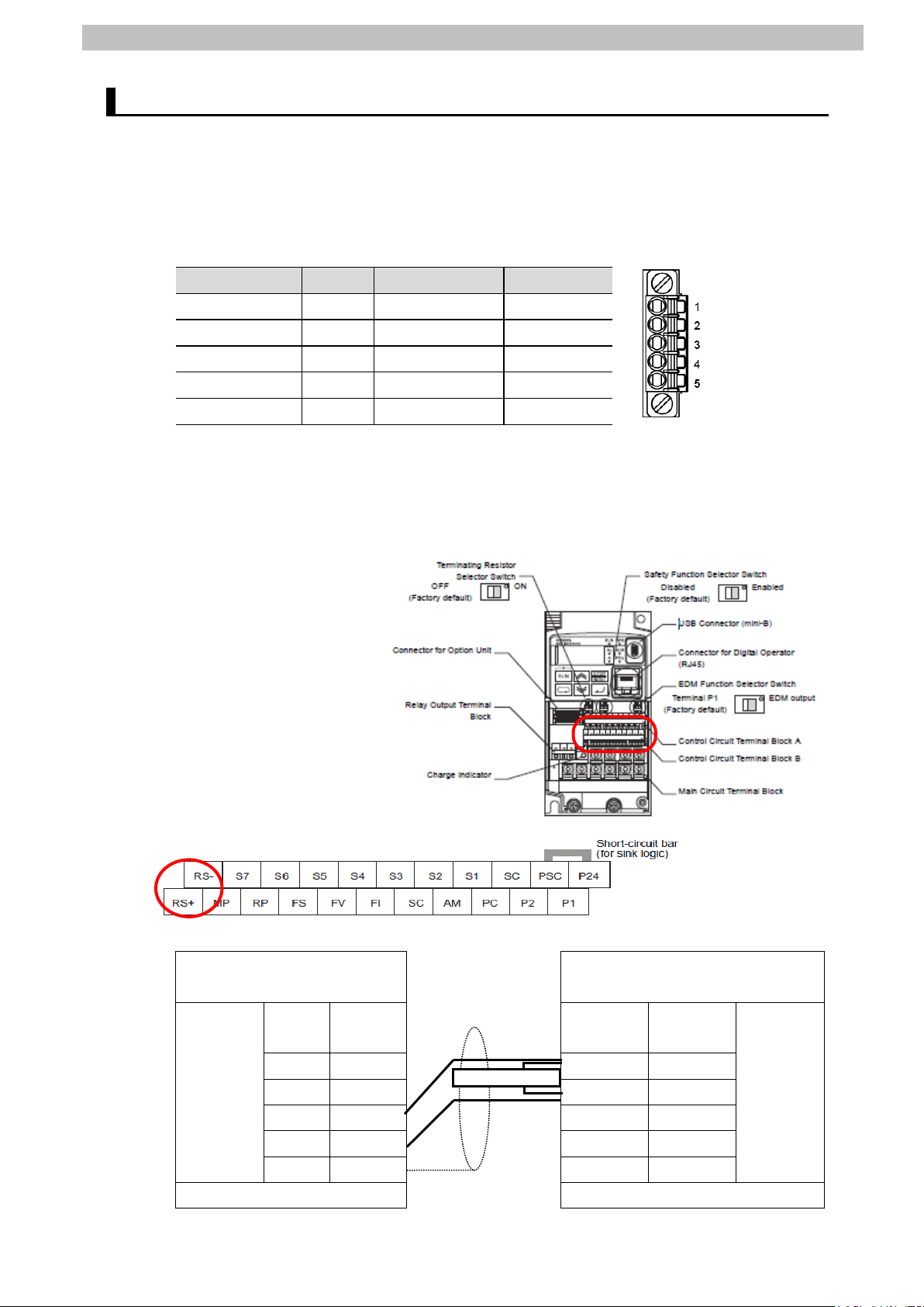
Pin No.
Symbol
Signal name
Input/Output
(CJ1W-SCU42).
Terminating resistor
6.2. Cable Wiring Diagram
Refer to SECTION 3 Installation and Wiring of the CJ Series Serial Communications Units
OPERATION MANUAL (Cat. No. W336) for details on cable wirings.
Check connector configurations and signal li nes (pin assignments) before wiring.
■Connector configurations and signal lines (pin assignments)
CJ1W-SCU42 Serial Communications Unit applicable connector: Terminal block
1(See note 1.) RDA Receive data - Input
2(See Note 1.) RDB Receive data + Input
3(See Note 1.) SDA Send data - Output
4(See Note 1.) SDB Send data + Output
5(See Note 2.) FG Shield -
Note 1: For 2-wire connection, use either pins 1 and 2 or pi ns 3 and 4.
Note 2: Pin 5 (Shield) is connected to the GR terminal on Power Supply Unit though Serial
Communications Unit. The cable shield can thus be grounded by grounding the GR
terminal of Power Supply Unit.
Inverter (3G3MX2-A[][][][]-V1) applicable connector: Terminal block
Control Circuit Terminal
■Cable/Pin assignments
Serial Communications Unit
RS-422A/
485
interface
Terminal block Terminal block
Signal
name
RDA- 1 A1 RSRDB+ 2 B1 RS+
SDA- 3
SDB+ 4
FG 5
Pin No. Terminal
Inverter (3G3MX2-A[][][][]-V1)
Signal
block
name
RS-485
interface
Page 15

7.Serial Communications Connection Procedure
10
7.2. Setting up Inverter
Set up Inverter.
Set the hardware switches on Inverter and connect
the cables.
Set the parameters for Inverter.
7.3. Setting up PLC
Set up PLC.
Set the hardware switches on Serial Communicati ons
Unit and connect the cables.
Start CX-Programmer, open the project file, and
Create the I/O table for PLC.
Set the parameters for Serial Communications Uni t.
7.3.5. Transferring the Project Data
Transfer the project data to PLC.
Communications
Start the send/receive processing and check that
Check that the correct data is written to the I/O
memory of PLC by using CX-Programmer.
7. Serial Communications Connection Procedure
This section describes the procedures for connecting PLC to Inverter using serial
communications.
In this document, the explanations of procedures for setting up PLC and Inverter are based on
the factory default settings. For the initializ ation, refer to Section 8. Initialization Method.
7.1. Work Flow
Take the following steps to connect PLC to Inverter using serial communications, and send
and receive messages.
↓
7.2.1. Hardware Settings
↓
7.2.2. Parameter Settings
↓
↓
7.3.1. Hardware Settings
↓
7.3.2. Opening the Project File and
Connecting Online with PLC
↓
7.3.3. Creating the I/O Table
↓
7.3.4. Parameter Settings
↓
connect online with PLC.
↓
7.4. Checking the Serial
↓
7.4.1. Checking the Receive Data
serial communications are normally performed.
Page 16
7.Serial Communications Connection Procedure
11
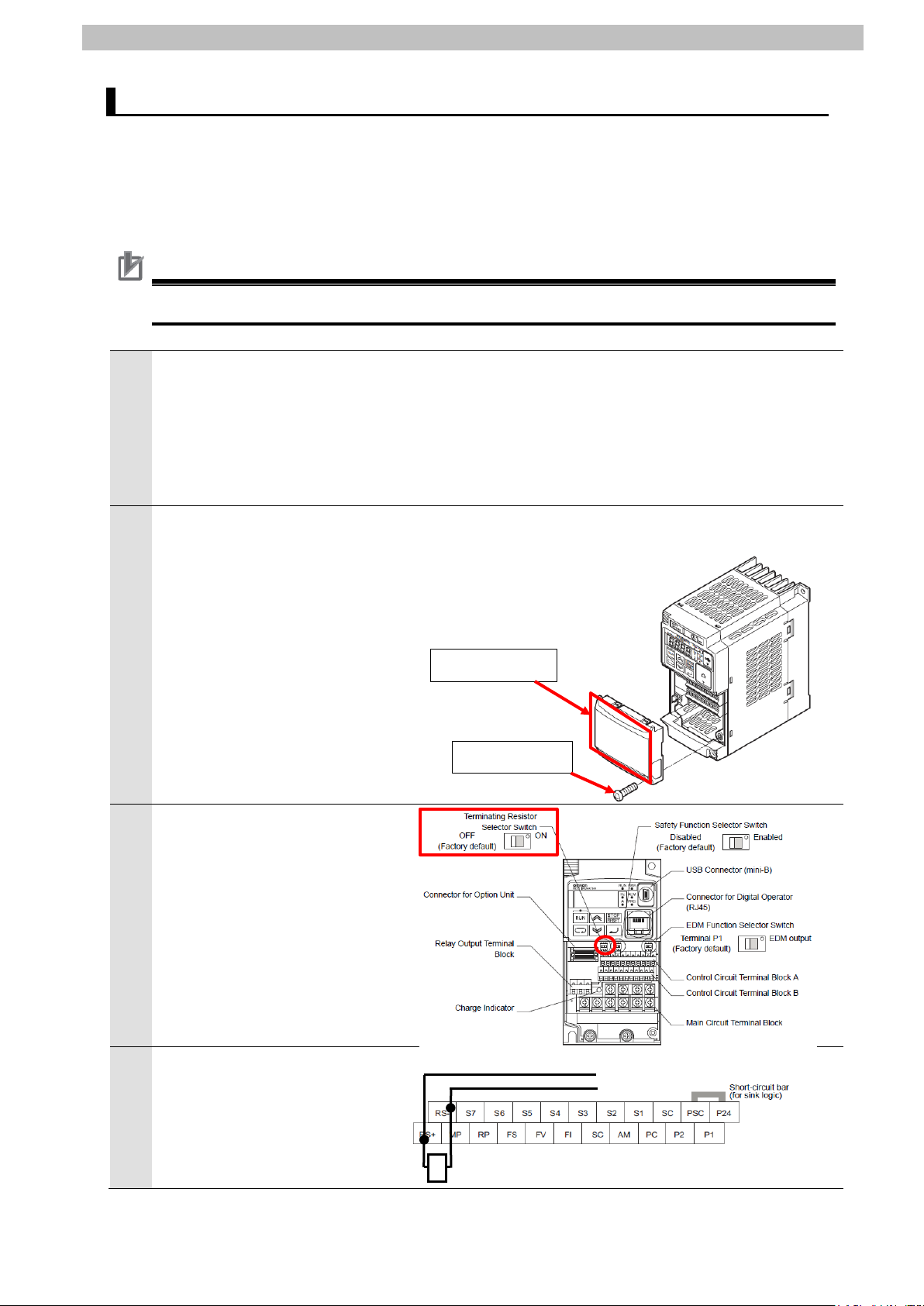
1
following procedure.
2
1: Loosen the mounting screw (x 1) from Option Unit Cover of the Inverter
3
Check that Terminating Resistor
4
Connect a Serial cable to
RS-485 terminal
Terminating resistor
Option Unit Cover
Mounting screw
Control Circuit
T erminal Block A
Control Circuit
Terminal Block B
SDB+
SDA-
7.2. Setting up Inverter
Set up Inverter.
7.2.1. Hardware Settings
Set the hardware switches on Inverter and connect the c abl es.
Precautions for Correct Use
Make sure that the power supply is OFF when you perform the setting up.
Make sure that the power supply
to Inverter is OFF.
*If the power supply is turned
ON, settings may not be
applicable as described in the
Remove Option Unit Cover from
the Inverter front panel as
shown in the right figure.
front panel.
2: Remove Option Unit Cover.
Selector Switch inside of the
terminal block cover is OFF.
RS-485 terminal (RS-, RS+).
Connect Terminating resistor
(120Ω 1/2W) to RS-485 terminal
(RS-, RS+).
Serial cable
Page 17

12
Connect 3-Phase 200 VAC
No. I585).
6
Main power supply input
3-Phase 200 VAC
Power supply
5
power supply to Main power
supply input terminal on Inverter
with a Power supply cable.
*For details on wiring
specifications of the power
supply, refer to 2-3 Wiring of
the Inverter Multi-function
Compact Inverter MX2 Series
Type V1 User’s Manual (Cat.
7.Serial Communications Connection Procedure
terminal
cable
power supply
Mount Option Unit Cover on the
Inverter front panel.
Page 18
13
7.2.2. Parameter Settings
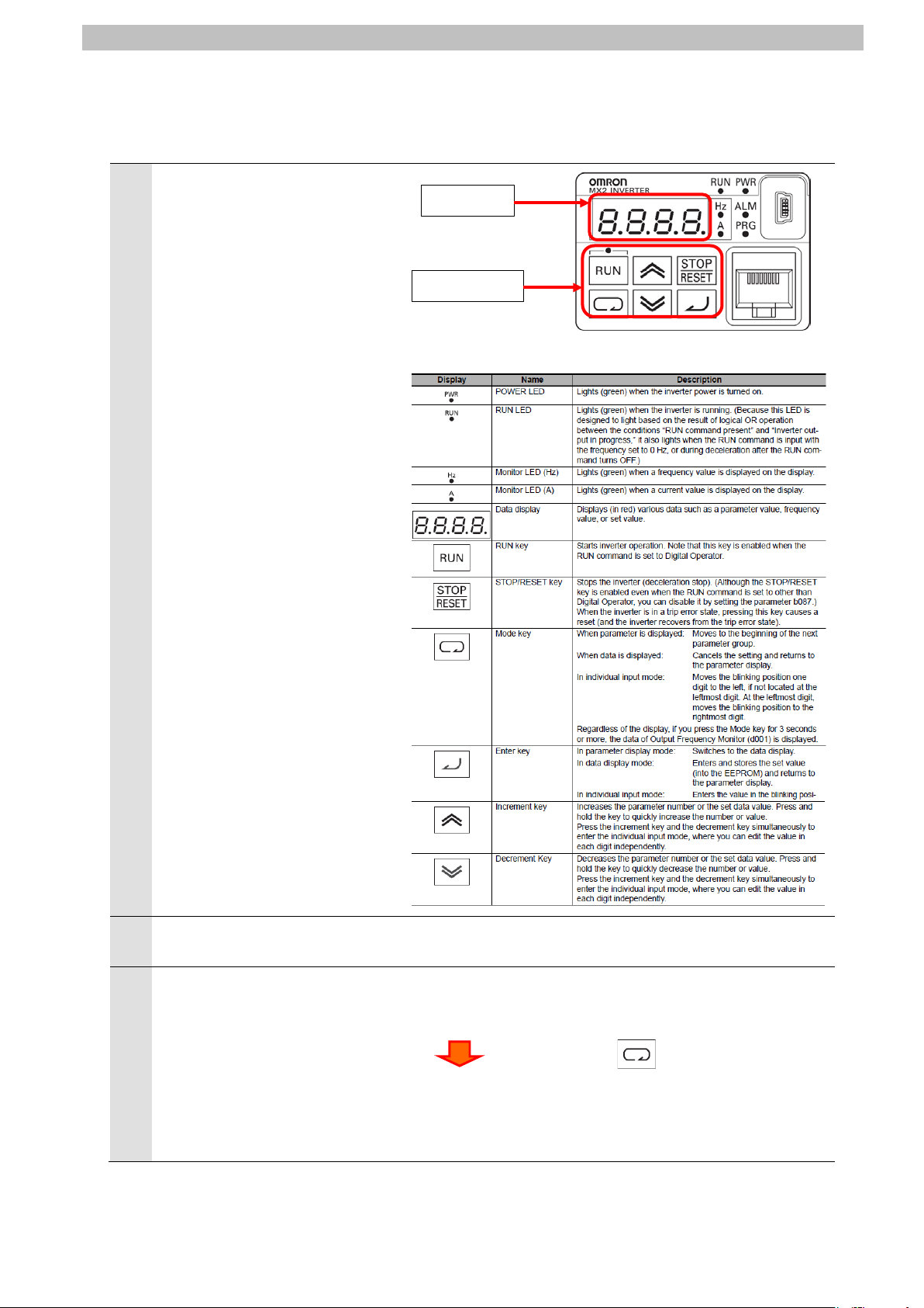
1
2
3
output frequency.
0.00
Data display
Operation keys
Data display.
Set the parameters for Inverter.
Check the positions of Data
display and Operation keys on
Digital Operator.
7.Serial Communications Connection Procedure
Digital Operator
Turn ON the power supply to
Inverter.
Use the procedure on the right
to display the parameters in the
extended function mode C.
*If the output frequency is not
displayed in Data display, press
and hold the Mode Key for 3
seconds or more to display the
The output frequency is displayed in
Press the Mode Key 5 times.
C001 parameter is displayed.
c001
Page 19

14
Use the procedure on the right
c001
c071
c071
c072
Check that the displayed value is the
Check that the displayed value is the
4
to set the parameters as follows:
C071 (Communication Speed
Selection): 05 (9600bps)
03: 2400bps 07: 38.4kbps
04: 4800bps 08: 57.6kbps
05: 9600bps 09: 76.8kbp
06: 19.2kbps 10: 115.2kbps
7.Serial Communications Connection Procedure
Press the Increment Key or
the Decrement Key to display
C071 parameter.
c071
05
Press the Enter Key.
C071 parameter is displayed.
Press the Enter Key.
default value ''05''.
*If the setting is different, change the
set value.
C071parameter is displayed again.
Use the procedure on the right
5
to set the parameters as follows:
C072 (Communication Station
No. Selection): 1.
Slave address: 1.
Setting range 1. to 247.
Press the Increment Key.
c072
Press the Enter Key.
1.
Press the Enter Key.
C072 parameter is displayed.
default value ''1.''.
*If the setting is different, change the
C072 parameter is displayed again.
set value.
Page 20

15
Use the procedure on the right
c072
c074
7
c074
c075
Check that the displayed value is the
set value.
Check that the displayed value is the
set value.
6
to set the parameters as follows:
C074 (Communication Parity
Selection): 00 (No parity)
00: No parity
01: Even parity
02: Odd parity
7.Serial Communications Connection Procedure
Press the Increment Key.
C074 parameter is displayed.
c074
Press the Enter Key.
default value ''00''.
00
Press the Enter Key.
*If the setting is different, change the
C074 parameter is displayed again.
Use the procedure on the right
to set the parameters as follows:
C075 (Communication Stop
Bit Selection): 01 (1 bit)
01: 1 bit
02: 2 bits
Press the Increment Key.
c075
Press the Enter Key.
01
Press the Enter Key.
C075 parameter is displayed.
default value ''01''.
*If the setting is different, change the
C075 parameter is displayed again.
Page 21

16
Use the procedure on the right
c075
c096
9
power supply again.
Check that the displayed value is the
set value.
8
to set the parameters as follows:
C096 (Communication
Selection): 00 (Modbus
communication)
00: Modbus communication
01: Co-inverter communication
02: Co-inverter communication
(management inverter)
7.Serial Communications Connection Procedure
Press the Increment Key or
the Decrement Key to display
C096 parameter.
C096 parameter is displayed.
c096
Press the Enter Key.
default value ''00''.
00
Press the Enter Key.
*If the setting is different, change the
Turn OFF the power supply to
Inverter.
*After connecting to PLC in the
procedure described on the
following page, turn ON the
C096 parameter is displayed again.
Page 22

7.Serial Communications Connection Procedure
17
1
following procedure.
the factory default setting.
TERM (Terminating resistance ON/OFF switch)
ON: Terminating resistance ON
WIRE (2-wire or 4-wire switch)
2:2-wire;4: 4-wire
7.3. Setting up PLC
Set up PLC.
7.3.1. Hardware Settings
Set the hardware switches on Serial Communicati ons Unit and connect the cables.
Precautions for Correct Use
Make sure that the power supply is OFF when you perform the setting up.
Make sure that the power supply
to PLC is OFF.
*If the power supply is turned
ON, settings may not be
applicable as described in the
Check the positions of hardware
2
switches on the front panel of
Serial Communications Unit by
referring to the right figure.
Set Unit number switch to 0.
3
*The unit number is set to 0 as
Set Terminating resistance
4
ON/OFF switch to ON
(Terminating res i stance ON).
Set 2-wire or 4-wire switch to 2
5
(2-wire).
OFF: Terminating resistance OFF
Page 23

18
Connect Serial Communications
PLC
Serial Communications Unit
End Cover
Serial cable
(RS-485)
Personal
USB cable
Power Supply Unit
CPU Unit
Inverter
6
Unit to PLC as shown on the
right.
Connect Inverter to Port 1 on
Serial Communications Unit with
a Serial cable (RS-485).
*For connections, refer to 6.2
Cable Wiring Diagram.
Connect Personal computer to
PLC with a USB cable.
7.Serial Communications Connection Procedure
computer
Page 24

7.Serial Communications Connection Procedure
19
1
PLC and Inverter.
2
start.
3
5
6
7.3.2. Opening the Project File and Connecting Online with PLC
Start CX-Programmer, open the project file, and connect online with PLC.
Install CX-Programmer and a USB driver on Personal c om puter beforehand.
Turn ON the power supplies to
Start CX-Programmer.
*If a confirmation dialog for an
access right is displayed at
start, execute a selection to
CX-Programmer starts.
Select Open from the File Menu.
4
The Open CX-Programmer
Project Dialog Box is displayed.
Select
OMRON_3G3MX2-V1_Mod485
_EV100.cxp and click Open.
*Obtain the project file from
OMRON.
After opening the project file,
select Programs in the project
workspace.
Page 25

20
Select Change Model from the
8
9
7
PLC Menu.
The Change PLC Dialog Box is
displayed.
From the pull-down list of Device
Type, select the device type of
PLC that you use.
Click Settings.
*CJ2M is selected in this
document.
7.Serial Communications Connection Procedure
The Device Type Settings
Dialog Box is displayed.
From the pull-down list of CPU
Type, select the CPU type that
you use.
Click OK.
*CPU12 is selected in this
document.
Page 26

7.Serial Communications Connection Procedure
21
11
Check that USB is set for
10
Network Type on the Change
PLC Dialog Box.
Click OK.
*If USB is not set for Network
Type, select USB from the
pull-down list.
*If you changed Device Type in
step 8 or CPU Type in step 9,
the dialog box on the right is
displayed. Check that there is
no problem and click Yes.
Make sure that the program
was normally converted. ("0
errors" must be shown.)
(Although duplicated output
warnings were detected in the
right dialog box, they are not
problems.)
Select Programs in the project
workspace.
Select Work Online from the
PLC Menu.
Page 27

22
A confirmation dialog box on the
during online connection.
Additional Information
Additional Information
12
right is displayed.
Check that there is no problem
and click Yes.
7.Serial Communications Connection Procedure
13
Check that CX-Programmer and
PLC are normally connected
online.
*The icon is press ed down
If PLC cannot be connected online, check the cable c onnection
After you check the cable connection, return to step 6, check the settings such as the
connection type in steps 7 to 9 and try again. For details, refer to Connecting Directly to a CJ2
CPU Unit Using a USB Cable of the CX-Programmer OPERATION MANUAL (Cat. No.
W446).
The dialog boxes explained in this document m ay not be displayed depending on the
environmental settings of CX-Programmer. For details on the environmental settings, refer to
Options and Preferences in CHAPTER 3 Projec t Reference in PART 1: CX-Programmer of
the CX-Programmer OPERATION MANUAL (Cat. No. W446).
This document explains the setting procedures when ''Confirm all operations affecting the
PLC'' is selected.
Page 28

23
7.3.3. Creating the I/O Table
1
Precautions for Correct Use
Create the I/O table for PLC.
If the operating mode of PLC is
Run Mode or Monitor Mode,
change it to Program Mode by
following the steps below.
(1)Select Operating Mode -
Program from the PLC Menu
of CX-Programmer.
(2)A confirmation dialog box on
the right is displayed. Check
that there is no problem and
click Yes.
*Refer to Additional Information
on the previous page for the
settings concerning the dialog
display.
(3)Check that Stop/Program
Mode is displayed on the right
of the PLC model in the
project workspace tree.
7.Serial Communications Connection Procedure
Select Edit - I/O Table and Unit
2
Setup from the PLC Menu of
CX-Programmer.
The PLC IO Table Window is
displayed.
The PLC will be reset after creating and transferring the I/O table in step 3 and subsequent
steps. Always confirm safety before creating and transferring the I/O table.
Page 29

24
Select Create from the Options
4
3
Menu in the PLC IO Table
Window.
A confirmation dialog box on the
right is displayed. Check that
there is no problem and click
Yes.
A confirmation dialog box on the
right is displayed. Check that
there is no problem and click
Yes.
7.Serial Communications Connection Procedure
The Transfer from PLC Dialog
Box is displayed.
Select IO Table and SIO Unit
Parameters and click Transfer.
When the transfer is completed,
the Transfer Results Dialog Box
is displayed.
Check that the transfer was
normally executed by referring
to the message in the dialog
box.
When the I/O table is created
normally, the dialog box displays
as follows:
Transfer Success: 1 Unit
Transfer Unsuccessful: 0 Unit
Click OK.
Page 30

7.Serial Communications Connection Procedure
25
1
2
3
7.3.4. Parameter Settings
Set the parameters for Serial Communications Uni t.
Double-click [0000] Main Rack
in the PLC IO Table Window to
expand the tree.
Right-click 00 [1500]
CJ1W-SCU42 and select Unit
Setup.
The View Parameters Dialog
Box is displayed.
Select Port1: Serial Gateway
Settings from the pull-down list
of Displayed Parameter.
Page 31

26
The setting items of Port1: Serial
5
6
4
Gateway Settings are listed as
shown in the right figure. (The
figure shows the default values.)
Select User settings from the
pull-down list of Set Value for
Port1: Port Settings.
7.Serial Communications Connection Procedure
Set the following parameters in
the same way as step 5.
・Serial communications mode
: Serial Gateway
・Data length: 8 bits
・Stop bits: 1 bit
・Parity: None
・Baud rate: Default(9600bps)
*Use the default settings for
other parameters.
Click Transfer[PC to Unit].
Page 32

27
A confirmation dialog box on the
8
9
7
right is displayed. Check that
there is no problem and click
Yes.
Check that the transfer is
completed as shown in the right
dialog box. Click Close.
7.Serial Communications Connection Procedure
A confirmation dialog box on the
right is displayed. Check the
contents and click Yes.
The Select Port Dialog Box is
displayed.
Select All ports and click OK.
The dialog box on the right is
displayed. Check the contents
and click OK.
Page 33

28
Click Compare on the View
12
13
10
Parameters Dialog Box.
7.Serial Communications Connection Procedure
Check that a message
11
"Compare successful" is
displayed in the dialog box on
the right. Click Close.
Click OK on the View
Parameters Dialog Box.
Select Exit from the File Menu
of the PLC IO Table Window to
close.
Page 34

29
1
2
3
7.Serial Communications Connection Procedure
7.3.5. Transferring the Project Data
Transfer the project data to PLC.
Select Programs in the project
workspace of CX-programmer.
Select Transfer - To PLC from
the PLC Menu.
Select Program(s), Comments,
and Program index.
Click OK.
*The I/O table and Special Unit
Setup are unnecessary to
transfer here, because they are
already set in 7.3.3. Creating
the I/O Table and 7.3.4.
Parameter Settings.
*The Comments and the
Program index Check Boxes
may not be displayed
depending on the device type.
In such a case, select
Program(s) only and transfer
the project data.
A confirmation dialog box on the
right is displayed. Check that
there is no problem and click
Yes.
Page 35

30
The dialog box on the right is
5
6
7
4
displayed (stating "Download
successful") when the transfer is
completed. Click OK.
Select Programs in the project
workspace. Select Transfer Compare with PLC from the
PLC Menu.
7.Serial Communications Connection Procedure
Select Program(s) and click OK.
Check that a message stating
"Compare successful" is
displayed. Click OK.
Page 36

7.Serial Communications Connection Procedure
31
Precautions for Correct Use
1
2
7.4. Checking the Serial Communications
Start the send/receive processing and check that serial communications are normally
performed.
If the PLC memory is changed by malfunction during monitoring power flow and
present value status in the Ladder Section Window or monitoring present values
in the Watch Window, the devices connected to output unit s may malfunction,
regardless of the operating mode of CPU Unit.
Confirm safety sufficiently before monitoring power fl ow and present value
status in the Ladder Section Window or in the Watch Window.
Check that a serial cable is connected before perform i ng the following procedure.
If it is not connected, turn OFF the power supply to each device, and then connect a serial
cable.
7.4.1. Checking the Receive Data
Check that the correct data is written to the I/O memory of PLC by using CX-Programmer.
Expand the Programs tree in the
project workspace of
CX-Programmer and
double-click Section1.
The Ladder Section Window
shows the Section1 ladder.
Ladder Section Window
Select Operating Mode Monitor from the PLC Menu.
Page 37

32
A confirmation dialog box on the
4
6
3
right is displayed. Check that
there is no problem and click
Yes.
Check that the operating mode
changes to Monitor Mode.
In the Ladder Section Window,
5
right-click Input_Start and select
Set - On.
7.Serial Communications Connection Procedure
Check that the Input_Start
contact is turned ON as shown in
the right figure.
*When the Input_Start contact is
turned ON, the send/receive
processing starts.
Page 38

33
Select Edit - Memory from the
8
9
11
7
PLC Menu.
Double-click CIO from the list in
the PLC Memory Window that is
displayed.
7.Serial Communications Connection Procedure
Enter 5500 in the Start Address
Field in the displayed CIO
Window.
Check that the start address
changes to CIO5500.
Select Monitor from the Online
10
Menu.
The Monitor Memory Areas
Dialog Box is displayed.
Select CIO and click Monitor.
Page 39

34
Check the received data in the
Function.
13
output frequency.
0.00
14
d001
d017
15
12
CIO Window shown on the right.
In the example on the right, the
stored data starting from
CIO5500 are in hexadecimal and
are described as follows:
・2804: Command code
・0000: End code
・01: Address number of Inverter
・03: Function code
・04: Number of bytes to read
・00, 00, 00, 62: Read data
*For details, refer to 9.2.2
Detailed Description of the
On Digital Operator, check the
values of Total Power ON Time
Monitor that are already read
out.
Press the Mode Key to display
the parameter of Monitor Mode
''d''.
*If the output frequency is not
displayed in Data display, press
and hold the Mode Key for 3
seconds or more to display the
7.Serial Communications Connection Procedure
Output frequency
Monitor Mode
d001
Parameter display
Press the Increment Key or the
Decrement Key to display d017.
Press the Enter Key to display
the total power ON time.
*For information on the display of
the total power ON time, refer to
7-1-16 Tot al Power ON Time
Monitor [d017] of the
Multi-function Compact Inverter
MX2 Series Type V1 User’s
Manual (Cat. No. I585).In the
example on the right, the total
power ON time shows 98, and it
accords with the read data
(00000062 in hexadecimal)
described in step 12.
( )
Total Power ON Time Monitor
Page 40

8.Initialization Method
35
8. Initialization Method
This document provides explanations of s etting procedures based on the factory default
settings.
Some settings may not be applicable as desc ri bed in t hi s document unless you use the
devices with the factory default settings.
8.1. Initializing PLC
To initialize the settings of PLC, it is necessary to initialize Serial Communications Unit and
CPU Unit. Change the operating mode of PLC to Program Mode before the initialization.
8.1.1. Serial Communications Unit
To initiali ze the settings of Serial Communications Unit, select Edit - I/O Table and Unit
Setup from the PLC Menu of CX-Programmer and perform the following steps.
(1) On the PLC IO Table Dialog Box, ri ght-click Serial Communications Unit and select Unit
Setup from the menu that is displayed.
(2) On the CJ1W-SCU42 [View Parameters] Dialog Box, click Set Defaults first, then click
Transfer[PC to Unit].
Page 41

8.Initialization Method
36
8.1.2. CPU Unit
To initiali ze the settings of CPU Unit, select Clear All Memory Areas from the PLC Menu of
CX-Programmer. Select Initialize on the Confirm All Memory Area Clear Dialog Box and click
OK.
8.2. Initializing Inverter
For information on how to initialize Inverter, refer to 5-1-2 Parameter Initialization of the
Multi-function Compact Inverter MX2 Series Type V1 User’s Manual (Cat. No. I585).
Page 42

9.Program
37
Additional Information
the disturbance such as electrical noise or the perf ormance variation of the device.
9. Program
This section describes the details on the program used in this document.
9.1. Overview
The following explains specifications and functions of the program that are used to check the
connection between OMRON Inverter (hereinafter referred to as Destination Device) and PLC
(Serial Communications Unit (hereinaft er referred to as SCU)).
This program performs the Modbus-RTU communication by CMND instruction (by using the
Serial Gateway function for SCU) to send and receive the command for Total Power ON Time
Monitor and detects a normal end or an error end.
A normal end of the send/receive processing means a normal end of the CMND instruction.
An error end means an error end of the CMND instruc tion and an error of Destination Device
(detected with the response data from Destinati on Devi ce).
Here, the "&" prefix is added to decimal data and the "#" prefix i s added to hexadecimal data
when it is necessary to distinguish between dec imal and hexadecimal data. (e.g., "&1000" for
decimal data and "#03E8" for hexadecimal data)
OMRON have confirmed that normal communic ations can be performed using this program
under 5.2. Device Configuration, however, we do not guarantee the normal operations under
Page 43

9.Program
38
PLC
CPU Unit
Serial Communications Unit
setting area
Serial Gateway
function
Command data
Response data
storage area
(2)Sends the command data
(Modbus-RTU communication)
(3)Executes the
(4)Receives the
CMND
(1) Executes the send
Communication is specified.)
9.1.1. Outline of Processing
The following figure shows the data flow from when PLC (SCU) issues command data to
Destination Device by using serial communi cations (Modbus-RTU communication) until when
it receives the response data from Destinati on Device.
(1)The ladder program executes the deliver command instruction (CMND instruction) for
which Modbus-RTU communication is specified.
(2)The command data of Total Power ON Time Monitor is sent to Inverter by Modbus-RTU
communication.
(3)The Inverter executes the command by receivi ng the command data from PLC and returns
the response data to PLC.
(4)The PLC receives the response data from Inverter and st ores in the specified address.
RS-485 Inverter
Ladder program
command instruction.
(CMND Instruction)
(The Modbus-RTU
CIO 5020 to 5023
Command Data
From CIO 5500
Response data
command and
returns the
response data.
response data and
stores it in the
specified memory.
Page 44

9.Program
39
Additional Information
28
Command
04
Command
code
Address
code
Data
+0CH
+1CH
**
**
**
**
**
Response
Command
code
Address
Function
code
End code
Data
28
04
+0CH
+1CH
+2CH
**
**
**
**
**
**
**
9.1.2. CMND Instructions and Send/Receive Messages
The following describes the network communic ations instruction (instruction word: CMND,
hereinafter referred to as CMND instruction) and outlines the basic operations of the
send/receive messages.
For details on the CMND instruction, refer to Network Instructions in SECTION 3 Instructions
of the CJ Series Programmable Controllers INST RUCT IONS REFERENCE MANUAL (Cat.
No. W474).
●CMND instruction operand data
S: First command word
・The first address is specified to set the send command.
・Data is sent from the first command word in the following format.
Function
*Command code #2804 is known as the FINS command for Modbus-RTU communication.
D: First response word
・The first address is specified to store the response.
・Data is received in the first response word in the following format.
Additional Information
For an address and a function code in the first command word, a defined device number by
Destination Device and a command code for a funct ion in executable status are set.
For details, refer to the manuals for Destination Devic e.
Page 45

9.Program
40
C: First control word
・The first address is specified to set the first control word.
・Data is set in the following format.
Item Description
Number of command data bytes The number of command data bytes is set. (#0002 to maximum data length)
Number of response data bytes The number of response data bytes is set . (#0000 to maximum data length)
Serial port number
(Physical port)
Destination network address One from the range of #00 to 7F is set. (#00: Own network)
Destination node address One from the range of #00 to the maximum node address is set.
Destination unit address The following (1) or (2) is set.
Response needed/not needed #0 or #8 is set. (#0: Response needed, #8: Response not need ed)
Logical port number One from the range of #0 to #7 is set.
Resend times One from the range of #0 to F (0 to 15 times) is set.
Response timeout One from the range of &1 to 65535 (#0001 to FFFF) (indicating 0.1 to
One from the range of #0 to #4 is set.
(#0: Not used, #1: Port 1, #2: Port 2, #3: Reserved, #4: Reserved)
*If you set the destination unit addres s to (2) Serial port's unit address as
described below, set #0: Not used.
(#00: Transmit within the local node)
(1)Unit address
CPU Unit : #00
CPU Bus Units : #10 + unit number
(e.g., for unit number (&5), Unit addr ess = #10 + #05 = #15)
Special I/O Unit : #20 + unit number
(e.g., for unit number (&10), Unit addr ess = #20 + #0A = #2A)
(2)Unit address of serial port
For SCU
Port 1: #80 + #04 x unit number
Port 2: #81 + #04 x unit number
(e.g., for Port 2 of unit number (&10),
Serial port's unit address = #81+#04×#0A(&10)= #81+#28=#A9)
6553.5 seconds) is set. (#0000: 2s ( default value))
Page 46

41
●Send/Receive messages
Additional Information
Overview of send/receive messages
S: Relation between the first command word (CMND ins truction operand) and the send
messages
9.Program
D: Relation between the receive messages and the first response word (CMND instruction
operand)
Silent interval: Waiting time to recognize the first frame using the Modbus-RTU
communication. During the reception standby, the first received data is deemed as the first
byte of frame after the waiting time of 3.5 characters with actual baud rate.
Additional Information
Error check: 16-bit data is expressed with two 8-bit data for the Modbus-RTU communication.
Error check result is calculated by the calculation formula called CRC (Cyclical Redundancy
Check).
Page 47

9.Program
42
Registers
Additional Information
9.2. Destination Device Command
The functions to read or write coils or registers are def ined as ''Modbus functions'' in the
Modbus-RTU communication. The Destination Device can be operated (comm and execution)
by using the Modbus functions to read or write coils or registers defined by Destination
Device.
9.2.1. Function Code List
In the Modbus functions, a function code is all ocated for each function. The following function
codes are available for Destination Device i n this document.
This program performs Total P ower ON Time Monitor by using the function '' Read from
Holding Register (function code: #03)''.
Code
(hex)
#01 Read Coil Status Reads the coil status (ON/OFF).
#03 Read from Holding
Register
#05 Write to Coil Writes the ON/OFF status to a single coil.
#06 Write to Holding
Register
#08 Loop-back Test Checks the communications between the mast er and the
#0F Write to Multiple Coils Rewrites the ON/OFF status to consecutive multiple
#10 Write to Multiple
Holding Registers
#17 Read/Write from/to
Multiple Holding
Function Description
Reads the contents of consecutive holding regist ers.
From the specified holding register, the specified number
of holding registers can be read.
Writes data to the specified holding register.
slave. Any value can be used for test data.
coils.
Writes data to consecutive multiple holding registers .
Reads data from and writes data to consecutive mul tiple
holding registers in a continuous manner.
For details on function codes, refer to 8-5 Explanati on of Each Function Code of the
Multi-function Compact Inverter MX2 Series Type V1 User’s Manual (Cat. No. I585).
Page 48

9.Program
43
Additional Information
No. I585).
CH
Contents
Data
Description
C
Number of command data bytes (4-digit hex)
#0008
8 bytes in S to S+3
C+1
Number of response data bytes (4-digit hex)
#000B
11 bytes from D to the upper byte of D+5
Upper
#0 (fixed)
#0 (fixed)
Serial port number (1-digit hex)
Not used.
Lower
Destination network address (2-digit hex)
Own network
Upper
Destination node address (2-digit hex)
Local node
Lower
Destination unit address (2-digit hex)
SCU number 0, Port 1
Upper
Response needed/not needed (1-digit hex)
Response needed
Logical port number (1-digit hex)
No.7 to use
#0 (fixed)
#0 (fixed)
Lower
Resend times (1-digit hex)
3 times
C+5
Response timeout (4-digit hex)
#0000
2s: Default value
CH
Contents
Data
Description
S
Command code (4-digit hex)
#2804
Modbus-RTU communication command
Upper
Slave address (2-digit hex)
#01: Destination Device address
Lower
Function code (2-digit hex)
#03: Read from Holding Register
S+2
Register address (4-digit hex) (= register number - 1).
#1016
Total Power ON Time Monitor
S+3
Number of read words (4-digit hex)
#0002
2 words
CH
Contents
Data
Description
D
Command code (4-digit hex)
#2804
Command code for S
D+1
End code (4-digit hex)
#
End code for FINS command
Upper
Slave address (2-digit hex)
#01: Slave address of S + 1
Lower
Function code (2-digit hex)
#03: Function code of S+1
Upper
Number of bytes to read (2-digit hex)
#04: Twice the number of read words S+3
Lower
Read data (first byte)
First byte of total power ON time
Upper
Read data (second byte)
Second byte of total power ON time
Lower
Read data (third byte)
Third byte of total power ON time
Upper
Read data (forth byte)
Forth byte of total power ON time
Lower
(Not used)
#00: (Not used)
9.2.2. Detailed Description of the Function
The following explains the details of Total Power ON Time Monitor (register number: #1017 to
#1018) performed by using ''Read from Holding Register (function code: #03)''.
For details on register addresses and register numbers, refer to 8-9 Modbus Communication
Data Lists of the Multi-function Compact Inverter MX 2 Series Type V1 User’s Manual (Cat.
●CMND instruction operand
・Setting contents of the first control word C (C: CIO 5010)
C+2
C+3
C+4
#0000
#0080
#0703
・Setting contents of the first command word S (S: CIO 5020)
S+1
#0103
・Storing contents of the first response word D (D: CI O 5500)
****
D+2
D+3
D+4
#0103
#04**
#****
D+5
●Send/Receive messages
・Send message Command data surrounded by bold lines above + CRC16 data (2 bytes)
・Receive message Response data surrounded by bold lines above + CRC16 data (2 bytes)
*CRC16: Error check code of send/receive data (When sending the data, the error check code
is automatically added in the send data by Modbus-RTU communication comm and.
After the error check code is automatically checked when rec ei ving the data, the
error check code is deleted from the receive data.)
#**00
Page 49

44
9.3. Error Detection Processing
01
03
10
16
00
02
Slave
address
Function
code
Number of read
words
01
83
Slave
address
Function
code + #80
Error
code
Additional Information
Serial cable
CJ2M-CPU12
CJ1W-SCU42
Destination Device
(1)
(2)
(3)
In this program, the error detection process i ng is performed by means of dividing the errors
into the following areas (1) to (3).
For details on error codes, refer to 9.7. Error Processing.
(1)Errors when executing the CMND instruc tion (CMND instruction error)
Errors such as the Unit error, the command format error, and the parameter error at the
execution of the CMND instruction are detect ed as CMND instruction errors. An error is
detected with Communications Port Error Flags (A 219.07) of related auxiliary area when
using the CMND instruction.
(2)Transmission errors when communicating with Destination Device (Communications error)
Errors occurred in communications with Destination Device, such as character corruption
and transmission errors caused by unmatched baud rate settings, are detected in CMND
instruction errors. Although the error is detected with (1), the allocated CIO area of SCU
''TransmissionErrorStatus (1508)'' is stored in the output area for the c om munication error
check.
(3)Errors in Destination Device (Desti nation Device errors)
Destination Device errors include function code error, register address error, data error, and
execution failure in Destination Device. An error is detected with the response data which is
returned from Destination Device. If an error occurs in Destination Device, a function code
that is obtained by adding #80 in the transmitted f unction code is returned (in this program,
#83 is returned when #03 is sent). This program detects an error bas ed on the difference
between the send/receive function codes.
9.Program
Send message
Receive
message
(at error)
Register address
**
CRC16
CRC16
For information on the CIO area allocated to SCU, refer to 9.4.2 List of Fixed Allocations.
Page 50

45
9.4. Memory Maps
Precautions for Correct Use
The following is the memory maps of this program.
9.4.1. Lists of Addresses
The tables below list the addresses necessary to execute this program.
You can change the allocation below to any addresses.
Make sure there is no duplicated address when changing an address.
●Input memory
The below address is used to operate this progra m.
Address Data type Variable name Description
5000.00 BOOL Input_Start When this flag changes from OFF to ON, the
send/receive processing start s .
9.Program
●Output memory
The execution results of the program are stored in these addresses.
Address Data type Variable name Description
5000.02 BOOL Output_NormalEnd Turns ON when the send/receive
processing ends normally.
5000.03 BOOL Output_ErrorEnd Turns ON when one or more of the following
errors occur.
(1)CMND instruction error
(2)Communications error
(3)Destination Device error
5500 UINT FirstResponseWord The received data is stored.
5501 UINT ResponseWord_1 The received d ata is stored.
5502 UINT ResponseWord_2 The received d ata is stored.
5503 WORD ResponseWord_3 The received data is stored.
5504 WORD ResponseWord_4 The received data is stored.
5505 WORD ResponseWord_5 The received data is stored.
H400 WORD Output_CMND_ErrorCode An Error code is stored when a CMND
instruction error occurs.
H401 WORD Output_TransmissionErrorStatus Content of transmission error status ''CIO
1508'' is stored when a communication error
occurs.
H402 WORD Output_DestinationDeviceErrorCode An error code receiv ed from Destination
Device is stored when an error occ ur s in
Destination Device.
Page 51

46
●Internal memory
These addresses are used to operate this program only.
Address Data type Variable name Description
5000.01 BOOL Local_CMND_Executing CMND instruction execution status is indicated.
5000.04 BOOL Local_CMND_NormalEnd Turns ON when a CMND instruction ends
5000.05 BOOL Local_CMND_ErrorEnd Turns ON when a CMND instruction error
5000.06 BOOL Local_DestinationDeviceError Turns ON when a Destination Device error
5010 UINT Local_FirstControlWord Execution parameter of CMND i ns truction
5011 UINT Local_ControlWord_1 Execution parameter of CMND instruction
5012 UINT Local_ControlWord_2 Execution parameter of CMND instruction
5013 UINT Local_ControlWord_3 Execution parameter of CMND instruction
5014 UINT Local_ControlWord_4 Execution parameter of CMND instruction
5015 UINT Local_ControlWord_5 Execution parameter of CMND instruction
5020 UINT Local_FirstCommandWord Send data of CMND instruct ion
5021 UINT Local_CommandWord_1 Send data of CMND instruction
5022 UINT Local_CommandWord_2 Send data of CMND instruction
5023 UINT Local_CommandWord_3 Send data of CMND instruction
9.Program
Turns ON when a CMND instruction is being
executed, and turns OFF when a CMND
instruction is not executed.
normally.
(including a communications error) occurs.
occurs.
Page 52

9.Program
47
Additional Information
Additional Information
9.4.2. List of Fixed Allocations
The tables below list the addresses necessary t o execut e this program.
●Allocated CIO area
The following is the fixed addresses determined by the unit address (unit number) that is set
for SCU. Therefore, you must not change these allocations.
Unit number 0 is used in this program.
Address Data type Variable name
1508.15 BOOL TransmissionError_SCU_0_P1
1508 WORD TransmissionErrorStatus_SCU_0_P1
For details on the allocated CIO area of SCU, refer to 2-3-2. CIO Area in 2-3. I/O Memory
Allocations in SECTION 2 Initial Sett ings and I/O Memory Allocations of the CJ Series Serial
Communications Units OPERATION MANUAL (Cat. No. W336).
●Related auxiliary area
The addresses of the following related auxiliary area are determined by the communications
port (internal logical port) specified in the pro gram (CMND operand). Therefore, you must
not change these allocations.
This program uses communications port (internal l ogical port) No. 7.
Address Data type Variable name
A202.07 BOOL CommPortEnabledFlag_P7
A219.07 BOOL CommPortErrorFlag_P7
A210 WORD CommPortCompletionCode_P7
For information on related auxiliary area for t he CMND instruction, refer to Related Auxiliary
Area Words and Bits in Network Instructions (CMND) in SECTION 3. Instructions of the CJ
Series Programmable Controllers INSTRUCTIONS REFERENCE MANUAL (Cat. No.
W474).
Page 53

48
9.5. Ladder program
processing.
9.5.1. Functional Components of the Ladder Program
The functional components of this program are shown bel ow.
Major classification Minor cl assification Description
1.Initialization
processing
2.CMND instruction
execution
management
1.1. Response code clear
1.2. Control word setting for
CMND instruction
1.3. Send/Receive symbol
setting
2.1. CMND instruction
executing
2.2. CMND instruction
execution processing
2.3. Normal/Error detection
The area of use is cleared and the
initialization setting is performed as a
preparation for communications.
CMND instruction (Modbus-RTU
communication) is executed. A normal end
or an error end is detected based on the
related flags and receive data.
9.Program
3.Normal end state
management
4.Error end state
management
3.1. Normal end processing
3.2. Response code setting
4.1. Error end processing
4.2. Response code setting
The normal completion flag is turned ON.
The response code for a normal end is set.
The error end flag is turned ON.
The response code corresponding to an
error cause is set.
9.5.2. Detailed Description of Each Functional Component
The program configured in this document is shown below.
●1. Initialization processing
No. Outline Description
1.1. Res ponse code
clear
The Error code storage area is initialized.
Page 54

9.Program
49
No. Outline Description
1.2. Control word setting
for CMND instruction
1.3. Send/Receive
symbol setting
The control word of CMND instruction is set.
For details on the settings, refer to 9.2.2. Detail ed
Description of the Function.
The FINS command and the Destination Device function are
set to the send symbol, and the receive data storage area i s
initialized.
Page 55

50
●2. CMND instruction execution management
processing
instruction is not being executed.
Precautions for Safe Use
Precautions for Correct Use
9.Program
ss
No. Outline Description
2.1. CMND i nstruction
executing
2.2. CMND i nstruction
execution
Make sure to sufficiently check the overall program before spec ifying the area to store the
receive data of the CMND instruction. Otherwise, t he data may be written to an unintended
memory area.
This program uses communications port (internal l ogical port) No.7.
Do not use communications port No.7 for other purpose. If you have no choice but to use
communications port No. 7, check that Communications Port Enabled Flag (A202.07) is ON.
CMND instruction executing status is entered.
The executing state is reset at a normal end or an error end
of the program.
CMND instruction is executed under the following
conditions: Communications port No.7 can be used. CMND
Page 56

9.Program
51
No. Outline Description
2.3. Normal/Error
Detection
Processing
Detects a normal end or an error end of the result of
send/receive processing.
It is identified as a normal end when all the foll owi ng conditions
are satisfied.
・Normal end of CMND instruction (No CMND instruction error)
(Condition of ''No communication error'' is included in (1).)
・Receives normal messages from Destination Devi ce
(No Destination Device error)
If any of the above errors occurs under the conditi ons above,
the corresponding error flag will turn ON.
Page 57

52
●3. Normal end state management
9.Program
No. Outline Description
3.1. Normal end
processing
3.2. Res ponse code
setting
Turns ON the normal end flag if it is detected in 2.3.
Normal/Error detection processing that the send/receive
processing ends normally.
Sets response code "#0000" for a normal end in the
response code storage area.
Page 58

53
Additional Information
●4. Error end state management
9.Program
No. Outline Description
4.1. Error end processing Turns ON the error end flag if it is detected in 2.3.
4.2. Res ponse code
setting
Refer to 9.7 Error Processing in this document for details on the response codes.
Normal/Error detection processing that the send/receive
processing ends in an error.
Sets the response code corresponding to the error in the
response code storage area when an error occurs.
Page 59

54
9.6. Timing Chart
Pattern
Normal end
Error end (1)
instruction error
Error end (2)
error
Error end (3)
Device error
Command
Normal
Error
Normal
Normal
Destination
Device
Normal
Normal or error
Normal or error
Error
Response
Yes
No
No
Yes
The timing charts are shown below.
The definitions of the timing chart patterns are as f ol lows:
9.Program
CMND
Communications
Destination
Page 60

55
9.7. Error processing
Main response code
Sub-response code
Main
Sub
Main response code
Sub-response code
02
05
Destination node error
Response timeout
10
04
Command format error
Command format error
25
05
Unit error
CPU Bus Error
Additional Information
Bit
Description
15
1: Transmission error 0: No transmission error
8 to 14
(Not used)
7
1: FCS check error 0: F CS check normal
6
(Not used)
5
1: Timeout error 0: Normal
4
1: Overrun error 0: Normal
3
1: Framing error 0: Normal
2
1: Parity error 0: Normal
0, 1
(Not used)
The following tables list the errors that oc cur during executing this program.
9.7.1. CMND Instruction Error Code
H400 stores the end code of the network communications instruction.
[Format]
Bit 15 8 7 0
[Response codes (Excerpt)]
9.Program
For details, refer to 5-1-3 End Codes in 5-1 Command Lists in SECTION 5 FINS Commands
of the CJ Series Communications Commands REF ERENCE MANUAL (Cat. No. W342).
Additional Information
For details on the CMND instruction error and troub l eshooting, refer to 12-3 Troubleshooting
in SECTION 12 Troubleshooting and Maintenance of the CJ Series Serial Communications
Units OPERATION MANUAL (Cat. No. W336).
9.7.2. Transmission error status
H401 stores contents of the transmission error st atus ''1508''.
[Contents of each bit in the transmission error status]
Page 61

56
9.7.3. Destination Device Error Code
#01
An unsupported function is specified.
Additional Information
Upper byte of H402 stores the following error codes.
[Format]
Bit 15 8 7 0
9.Program
Error code
#Always #00
[Error code list]
Error code (hex) Description
#02 The specified address does not exist.
#03 The specified data is in an unacceptable format.
#21 Writing to a holding register is specified, but the data is out of the range
allowed for the inverter.
#22 The inverter does not allow this function because:
・Function attempts to change a register that cannot be changed
during RUN.
・Function attempts to issue the Enter command during RUN (UV
・Function attempts to write data to a register during trip (UV
・Function attempts to write data to a register on which the soft lock
function is enabled.
・Function attempts to change an I/O terminal that cannot be
changed.
・Function attempts to change the contact type of the term inal to
which the RS (Reset) is allocated.
・Function attempts to write data to a register when t he auto-tuning
function is enabled.
・Function attempts to write data to a password-locked register when
the password function is enabled.
etc.
*1. UV: Undervoltage
#23 Func tion attempts to write data to a read-only register (coil).
*1
).
*1
).
For details and troubleshooting on the Desti nation Device errors, refer to 8-4-4 Abnormal
Response in 8-4 Modbus Communication Protocol of the Multi-function Compact Inverter
MX2 Series Type V1 User’s Manual (Cat. No. I585).
Page 62

57
10. Revision History
code
Revision
01 November 16, 2015 First edition
Date of revision Revision r easo n an d r evision page
10.Revision History
Page 63

58
Page 64

2015
P641-E1-01
1115- (-)
 Loading...