

Omron 3G3MX2-V1 Series, 3G3MX2-A2004-V1, 3G3MX2-A2001-V1, 3G3MX2-A2002-V1, 3G3MX2-A2007-V1 User Manual
...Page 1
Multi-function Compact Inverter
MX2 Series Type V1
User’s Manual
I585-E1-01
3G3MX2-A-V1
Page 2

OMRON, 2013
All rights reserved. No part of this publication may be reproduced, stored in a retrieval system, or transmitted, in any
form, or by any means, mechanical, electronic, photocopying, recording, or otherwise, without the prior written
permission of OMRON.
No patent liability is assumed with respect to the use of the information contained herein. Moreover, because OMRON
is constantly striving to improve its high-quality products, the information contained in this manual is subject to change
without notice. Every precaution has been taken in the preparation of this manual. Nevertheless, OMRON assumes no
responsibility for errors or omissions. Neither is any liability assumed for damages resulting from the use of the
information contained in this publication.
Page 3

1
Introduction
Multi-function Compact Inverter 3G3MX2-V1 User’s Manual (I585-E1)
Introduction
Thank you for purchasing the Multi-function Compact Inverter (Model: 3G3MX2--V1).
This manual describes the installation and wiring methods of the 3G3MX2-V1 Series Inverter, and
parameter setting methods which are required for the operation, as well as troubleshooting and inspection methods.
This manual is intended for the following personnel, who must also have knowledge of electrical systems (an electrical engineer or the equivalent).
• Personnel in charge of introducing the control equipment
• Personnel in charge of designing the control systems
• Personnel in charge of installing and maintaining the control equipment
• Personnel in charge of managing the control systems and facilities
This manual contains information you need to know to correctly use the Multi-function Compact Inverter
(Model: 3G3MX2--V1).
Before using the inverter, read this manual and gain a full understanding of the information provided
herein.
After you finished reading this manual, keep it in a convenient place so that it can be referenced at any
time.
Make sure this manual is delivered to the end user.
Intended Readers
Notice
Page 4

Manual Configuration
2
Multi-function Compact Inverter 3G3MX2-V1 User’s Manual (I585-E1)
Manual Configuration
This manual is compiled section by section for user’s convenience as follows.
Section Overview
Section 1 Overview This section provides an overview of the 3G3MX2-V1
Series features, standard specifications, and external
dimensions by inverter capacity. It also shows the differences of this inverter from the conventional inverter for
those who use the previous model.
Section 2 Design This section describes the installation environment and wir-
ing methods.
Section 3 Operation and Test Run This section describes the part names and key operation of
the Digital Operator, and the operation method of this product as well as the test run procedure.
Section 4 Parameter List This section provides the parameter lists that show monitor
functions and available parameters for this inverter.
Section 5 Basic Settings This section describes the basic functions such as the Run
command.
Section 6 Vector Control and Applied Functions This section describes the vector control and applied func-
tions characteristic of this inverter.
Section 7 Other Functions This section describes the details of functions not described
in Section 5 or Section 6.
Section 8 Communications Functions This section describes the general-purpose serial commu-
nications functions (Modbus communication).
Section 9 Overview of DriveProgramming This section provides the features of the DriveProgram-
ming.
Section 10 Troubleshooting This section describes how to analyze the cause and take
countermeasures if the inverter fails, and provides troubleshooting for possible troubles.
Section 11 Maintenance and Inspection This section describes the maintenance and periodical
inspection items.
Section 12 Options This section describes the specifications and external
dimension of optional equipment.
Appendices This section provides information on derating, capacitor life
curve, compliance with the UL/cUL Standards, and inverter
selection.
Page 5
3
Manual Structure
Multi-function Compact Inverter 3G3MX2-V1 User’s Manual (I585-E1)
Manual Structure
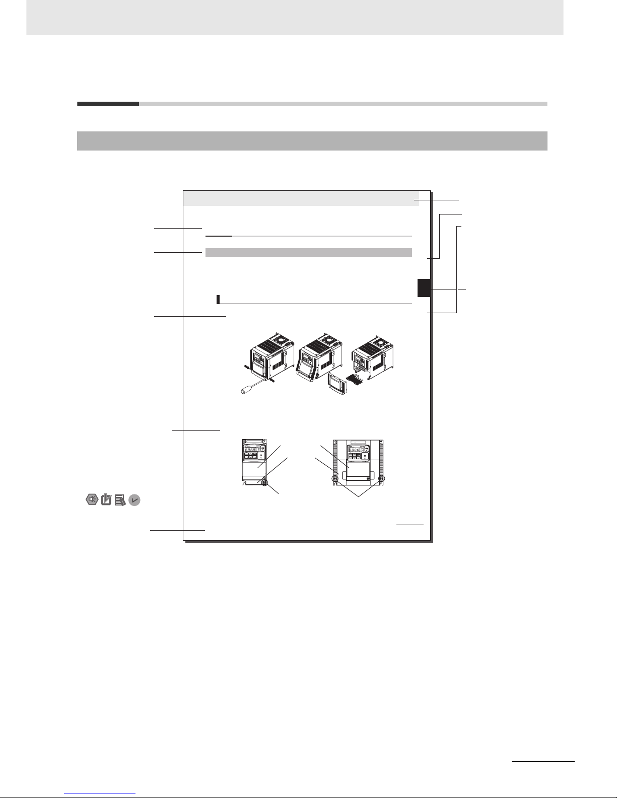
The following page structure and symbol icons are used in this manual.
Note The above page is only a sample for illustrative purposes. It is not the actual content of the manual.
Page Structure and Symbol Icons
2 - 7
2 Design
Multi-function Compact Inverter 3G3MX2-V1 User’s Manual (I585-E1)
2-2 Removal of Each Part
2
2-2-1 Removing Covers
2-2 Removal of Each Part
Before wiring each terminal block, you need to remove the terminal block cover and the backing plate.
This section describes how to remove these covers.
To install a communications unit or option unit, you must remove the option unit cover beforehand.
For how to install an option unit, refer to the user’s manual for each option unit.
1 Loosen the terminal block cover fixation screw(s).
2 Remove the terminal block cover from the bottom, while pressing its lower sides in the
directions of the arrows.
You can find one terminal block cover fixation screw at the lower right of the cover for Inverters
with a capacity of 3.0 kW or lower, or two terminal block cover fixation screws on both sides of
the cover for Inverters with a capacity of 3.7 kW or higher.
Also note that the option unit cover is screwed to the terminal block cover, but not fixed to the
Inverter body. Therefore, you can remove the terminal block cover without removing the option
unit cover.
2-2-1 Removing Covers
Removing Terminal Block Cover
Press in the arrow
directions to remove
the terminal block
cover from the bottom.
Option unit cover
Terminal block
cover
Terminal block cover
fixation screw
(1 for 3.0 kW or lower)
Terminal block cover
fixation screw
(2 for 3.7 kW or higher)
Level 1 heading
Level 2 heading
Level 3 heading
Level 2 heading
Operation Steps
Manual Name
Note, Supplementary
Information, Reference
Target
Level 3 heading
Section Number
of Level 1 heading
Shows which
paragraph the content
of the current page
belongs to.
Describes the operation
steps.
A note, supplementary
information, reference
target, etc. are provided
with difference icons.
Shows which
section the content
of the current
page belongs to.
Page 6

Manual Structure
4
Multi-function Compact Inverter 3G3MX2-V1 User’s Manual (I585-E1)
Special information in this manual is classified as follows:
Precautions for Safe Use
Precautions on what to do and what not to do to ensure safe usage of the product.
Precautions for Correct Use
Precautions on what to do and what not to do to ensure proper operation and performance.
Additional Information
Additional information to read as required.
This information is provided to increase understanding or make operation easier.
Special Information
Page 7
5
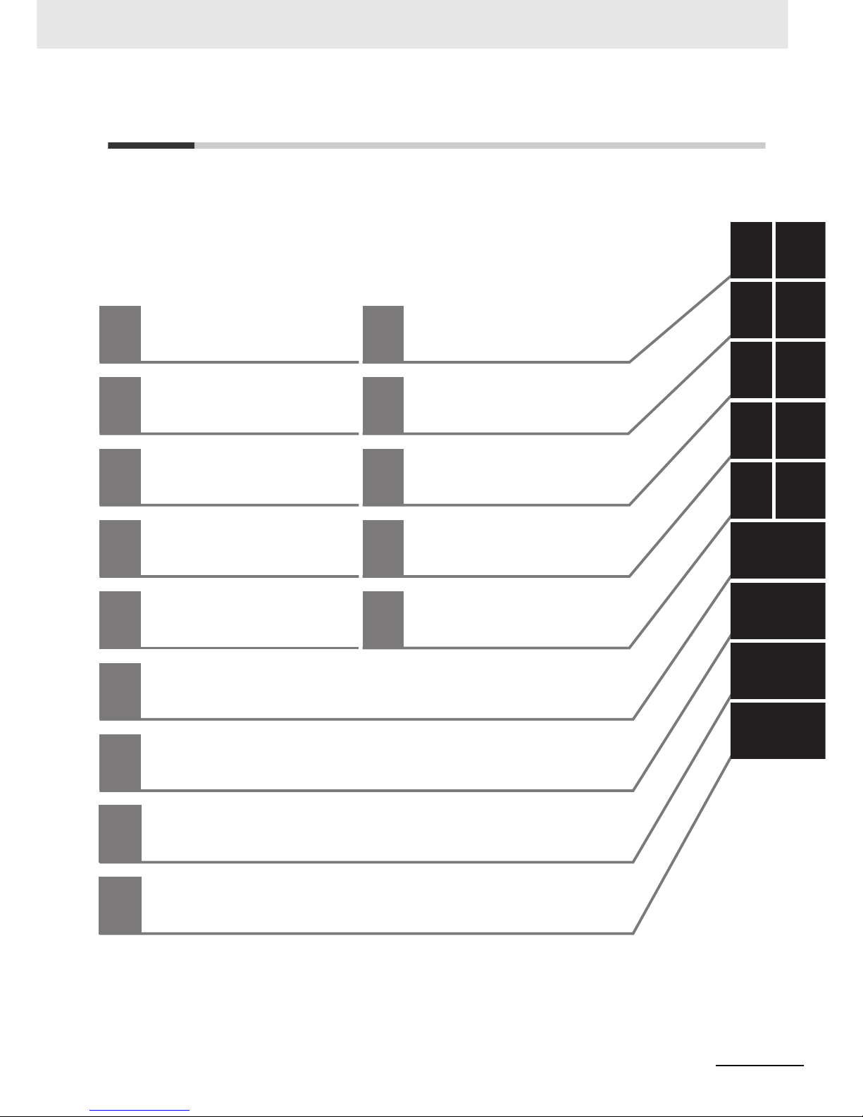
Sections in this Manual
Multi-function Compact Inverter 3G3MX2-V1 User’s Manual (I585-E1)
1
10
2
11
3
12
4A
5
6
7
8
9
1
10
2
11
3
12
4A
5I
6
7
8
9
Overview Troubleshooting
Design
Maintenance and
Inspection
Operation and Test Run
Options
Parameter List Appendices
I
IndexBasic Settings
Vector Control and Applied Functions
Other Functions
Communications Functions
Overview of DriveProgramming
Sections in this Manual
Page 8

Terms and Conditions Agreement
6
Multi-function Compact Inverter 3G3MX2-V1 User’s Manual (I585-E1)
Terms and Conditions Agreement
Please read and understand this manual before purchasing the products. Please consult your OMRON
representative if you have any questions or comments.
z Exclusive Warranty
Omron’s exclusive warranty is that the Products will be free from defects in materials and workmanship for a period of twelve months from the date of sale by Omron (or such other period expressed in
writing by Omron). Omron disclaims all other warranties, express or implied.
z Limitations
OMRON MAKES NO WARRANTY OR REPRESENTATION, EXPRESS OR IMPLIED, ABOUT
NON-INFRINGEMENT, MERCHANTABILITY OR FITNESS FOR A PARTICULAR PURPOSE OF
THE PRODUCTS. BUYER ACKNOWLEDGES THAT IT ALONE HAS DETERMINED THAT THE
PRODUCTS WILL SUITABLY MEET THE REQUIREMENTS OF THEIR INTENDED USE.
Omron further disclaims all warranties and responsibility of any type for claims or expenses based
on infringement by the Products or otherwise of any intellectual property right.
z Buyer Remedy
Omron’s sole obligation hereunder shall be, at Omron’s election, to (a) replace (in the form originally
shipped with Buyer responsible for labor charges for removal or replacement thereof) the non-complying Product, (b) repair the non-complying Product, or (c) repay or credit Buyer an amount equal to
the purchase price of the non-complying Product; provided that in no event shall Omron be responsible for warranty, repair, indemnity or any other claims or expenses regarding the Products unless
Omron’s analysis confirms that the Products were properly handled, stored, installed and maintained and not subject to contamination, abuse, misuse or inappropriate modification. Return of any
Products by Buyer must be approved in writing by Omron before shipment. Omron Companies shall
not be liable for the suitability or unsuitability or the results from the use of Products in combination
with any electrical or electronic components, circuits, system assemblies or any other materials or
substances or environments. Any advice, recommendations or information given orally or in writing,
are not to be construed as an amendment or addition to the above warranty.
See http://www.omron.com/global/ or contact your Omron representative for published information.
OMRON COMPANIES SHALL NOT BE LIABLE FOR SPECIAL, INDIRECT, INCIDENTAL, OR CONSEQUENTIAL DAMAGES, LOSS OF PROFITS OR PRODUCTION OR COMMERCIAL LOSS IN ANY
WAY CONNECTED WITH THE PRODUCTS, WHETHER SUCH CLAIM IS BASED IN CONTRACT,
WARRANTY, NEGLIGENCE OR STRICT LIABILITY.
Further, in no event shall liability of Omron Companies exceed the individual price of the Product on
which liability is asserted.
Read and understand this Manual
Warranty, Limitations of Liability
Warranties
Limitation on Liability; Etc
Page 9

7
Terms and Conditions Agreement
Multi-function Compact Inverter 3G3MX2-V1 User’s Manual (I585-E1)
Omron Companies shall not be responsible for conformity with any standards, codes or regulations
which apply to the combination of the Product in the Buyer’s application or use of the Product. At
Buyer’s request, Omron will provide applicable third party certification documents identifying ratings
and limitations of use which apply to the Product. This information by itself is not sufficient for a complete determination of the suitability of the Product in combination with the end product, machine, system, or other application or use. Buyer shall be solely responsible for determining appropriateness of
the particular Product with respect to Buyer’s application, product or system. Buyer shall take application responsibility in all cases.
NEVER USE THE PRODUCT FOR AN APPLICATION INVOLVING SERIOUS RISK TO LIFE OR
PROPERTY OR IN LARGE QUANTITIES WITHOUT ENSURING THAT THE SYSTEM AS A WHOLE
HAS BEEN DESIGNED TO ADDRESS THE RISKS, AND THAT THE OMRON PRODUCT(S) IS
PROPERLY RATED AND INSTALLED FOR THE INTENDED USE WITHIN THE OVERALL EQUIPMENT OR SYSTEM.
Omron Companies shall not be responsible for the user’s programming of a programmable Product, or
any consequence thereof.
Data presented in Omron Company websites, catalogs and other materials is provided as a guide for
the user in determining suitability and does not constitute a warranty. It may represent the result of
Omron’s test conditions, and the user must correlate it to actual application requirements. Actual performance is subject to the Omron’s Warranty and Limitations of Liability.
Product specifications and accessories may be changed at any time based on improvements and other
reasons. It is our practice to change part numbers when published ratings or features are changed, or
when significant construction changes are made. However, some specifications of the Product may be
changed without any notice. When in doubt, special part numbers may be assigned to fix or establish
key specifications for your application. Please consult with your Omron’s representative at any time to
confirm actual specifications of purchased Product.
Information presented by Omron Companies has been checked and is believed to be accurate; however, no responsibility is assumed for clerical, typographical or proofreading errors or omissions.
Application Considerations
Suitability of Use
Programmable Products
Disclaimers
Performance Data
Change in Specifications
Errors and Omissions
Page 10
Safety Precautions
8
Multi-function Compact Inverter 3G3MX2-V1 User’s Manual (I585-E1)
Safety Precautions
To ensure that the Multi-function Compact Inverter (Model: 3G3MX2--V1) is used safely and correctly,
be sure to read this Safety Precautions section and the main text before using the product.
Learn all items you should know before use, regarding the equipment as well as required safety information and precautions.
Make an arrangement so that this manual also gets to the end user of this product.
After reading this manual, keep it in a convenient place so that it can be referenced at any time.
In this user’s manual, the following precautions and signal words are used to provide information to
ensure the safe use of the Multi-function Compact Inverter (Model: 3G3MX2--V1).
The information provided here is vital to safety. Strictly observe the precautions provided.
Indications and Meanings of Safety Information
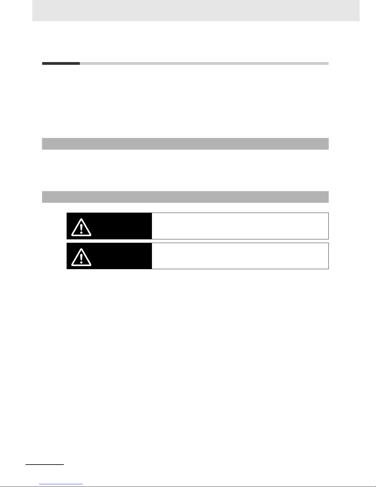
Meanings of Signal Words
WARNING
Indicates an imminently hazardous situation which, if not avoided, is likely
to result in serious injury or may result in death. Additionally there may be
severe property damage.
CAUTION
Indicates a potentially hazardous situation which, if not avoided, may result
in minor or moderate injury or in property damage.
Page 11
9
Safety Precautions
Multi-function Compact Inverter 3G3MX2-V1 User’s Manual (I585-E1)
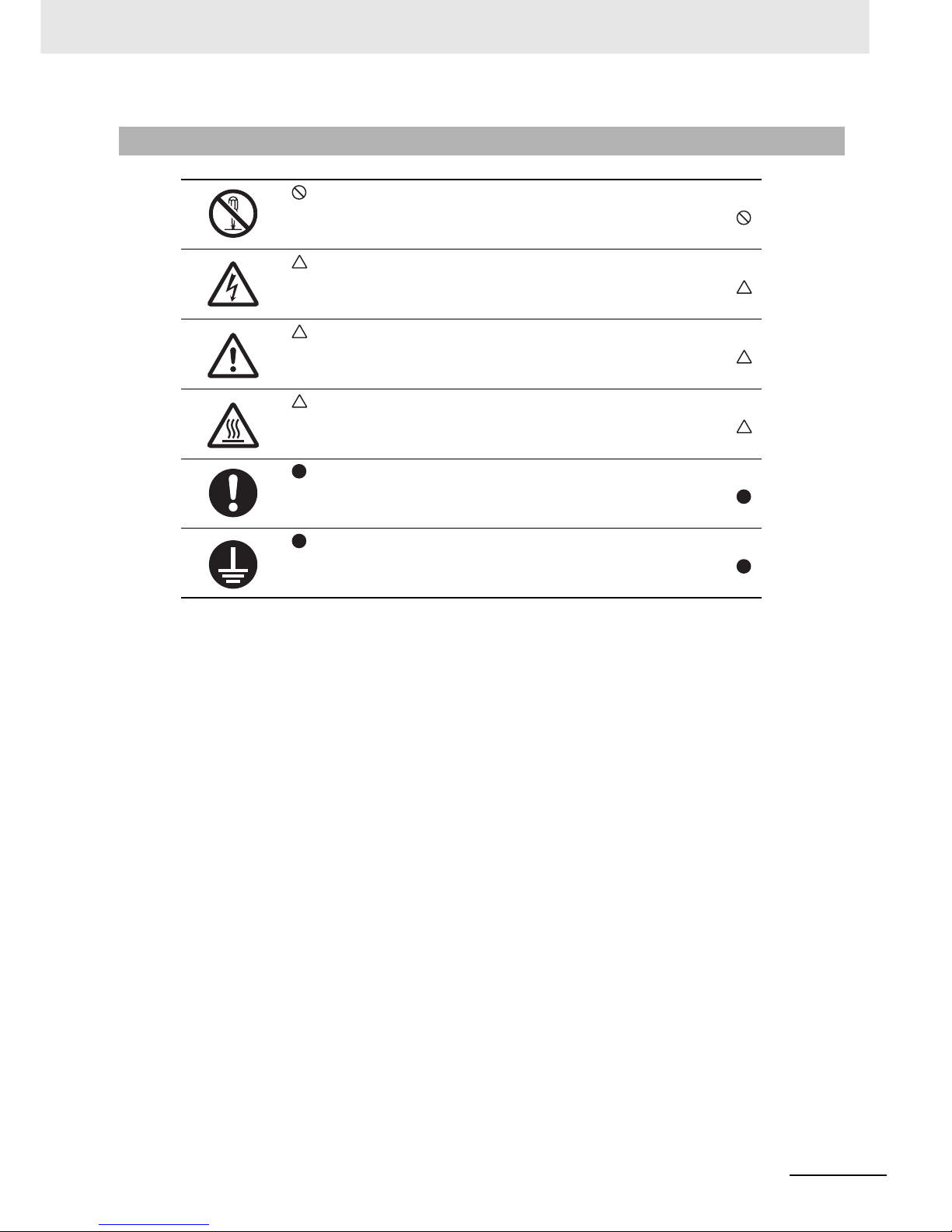
Explanation of Symbols
This symbol indicates a prohibited item (an item you must not do).
The specific instruction is indicated using an illustration or text inside or near .
The symbol shown to the left indicates “disassembly prohibited.”
This symbol indicates danger and caution.
The specific instruction is indicated using an illustration or text inside or near .
The symbol shown to the left indicates “beware of electric shock.”
This symbol indicates danger and caution.
The specific instruction is indicated using an illustration or text inside or near .
The symbol shown to the left indicates “non-specific general danger.”
This symbol indicates caution (warnings included).
The specific instruction is indicated using an illustration or text inside or near .
The symbol shown to the left indicates “risk of hot surface.”
This symbol indicates a compulsory item (an item that must be done).
The specific instruction is indicated using an illustration or text inside or near .
The symbol shown to the left indicates “general compulsory items.”
This symbol indicates a compulsory item (an item that must be done).
The specific instruction is indicated using an illustration or text inside or near .
The symbol shown to the left indicates “grounding required.”
Page 12
Safety Precautions
10
Multi-function Compact Inverter 3G3MX2-V1 User’s Manual (I585-E1)
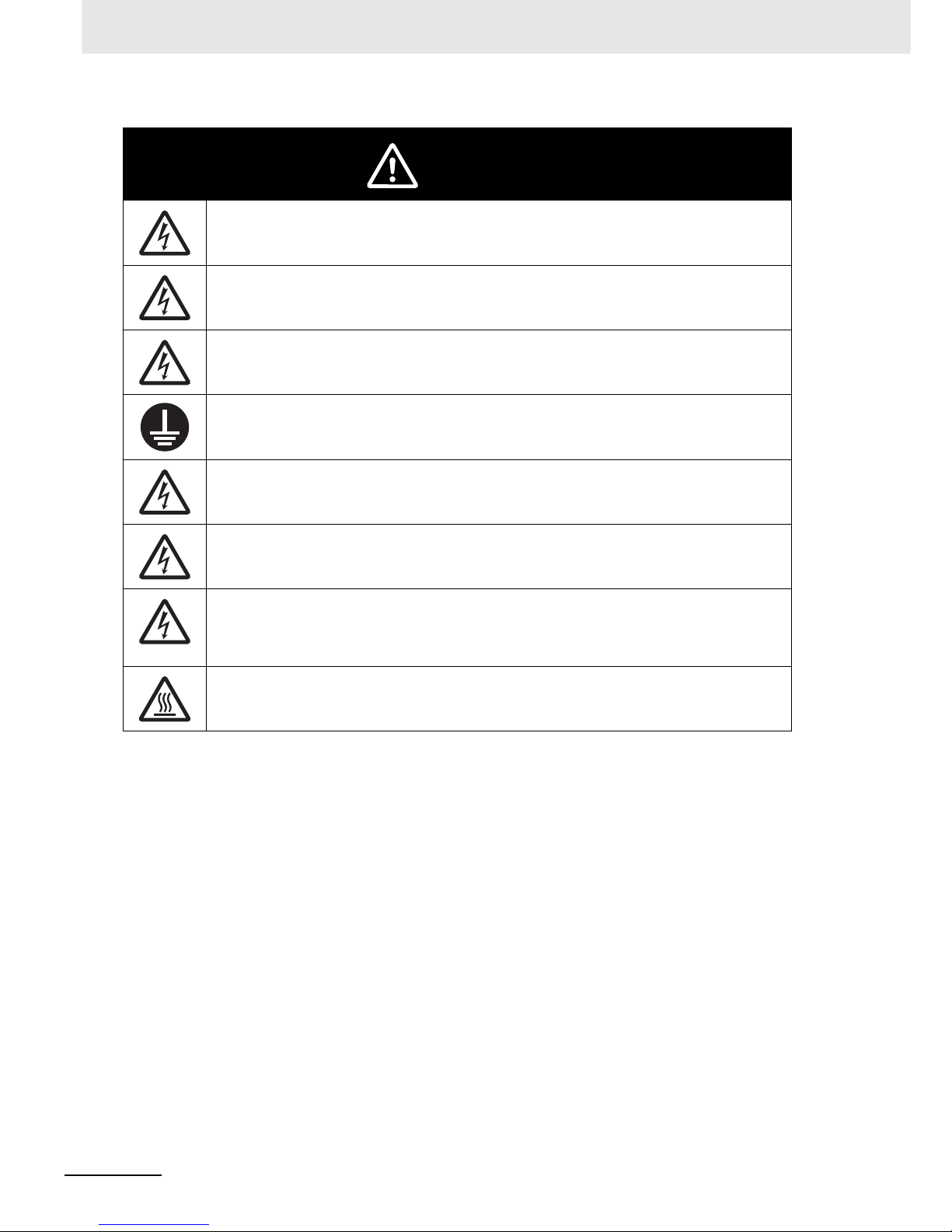
WARNING
Turn off the power supply and implement wiring correctly.
Not doing so may result in a serious injury due to an electric shock.
Wiring work must be carried out only by qualified personnel.
Not doing so may result in a serious injury due to an electric shock.
Do not change wiring and slide switches, put on or take off Operator and optional devices, replace
cooling fans while the input power is being supplied. Doing so may result in a serious injury due to
an electric shock.
Be sure to ground the unit.
Not doing so may result in a serious injury due to an electric shock or fire.
(200-V class: type-D grounding, 400-V class: type-C grounding)
Do not remove the terminal cover during the power supply and 10 minutes after the power shut off.
Doing so may result in a serious injury due to an electric shock.
Do not operate the Digital Operator or switches with wet hands.
Doing so may result in a serious injury due to an electric shock.
Inspection of the inverter must be conducted after the power supply has been turned off. Not doing
so may result in a serious injury due to an electric shock.
The main power supply is not necessarily shut off even if the emergency shut off function is activated.
Do not touch the inverter cooling fins, braking resistors, and the motor, which become too hot during the power supply and for some time after the power shut off. Doing so may result in a burn.
Page 13
11
Safety Precautions
Multi-function Compact Inverter 3G3MX2-V1 User’s Manual (I585-E1)
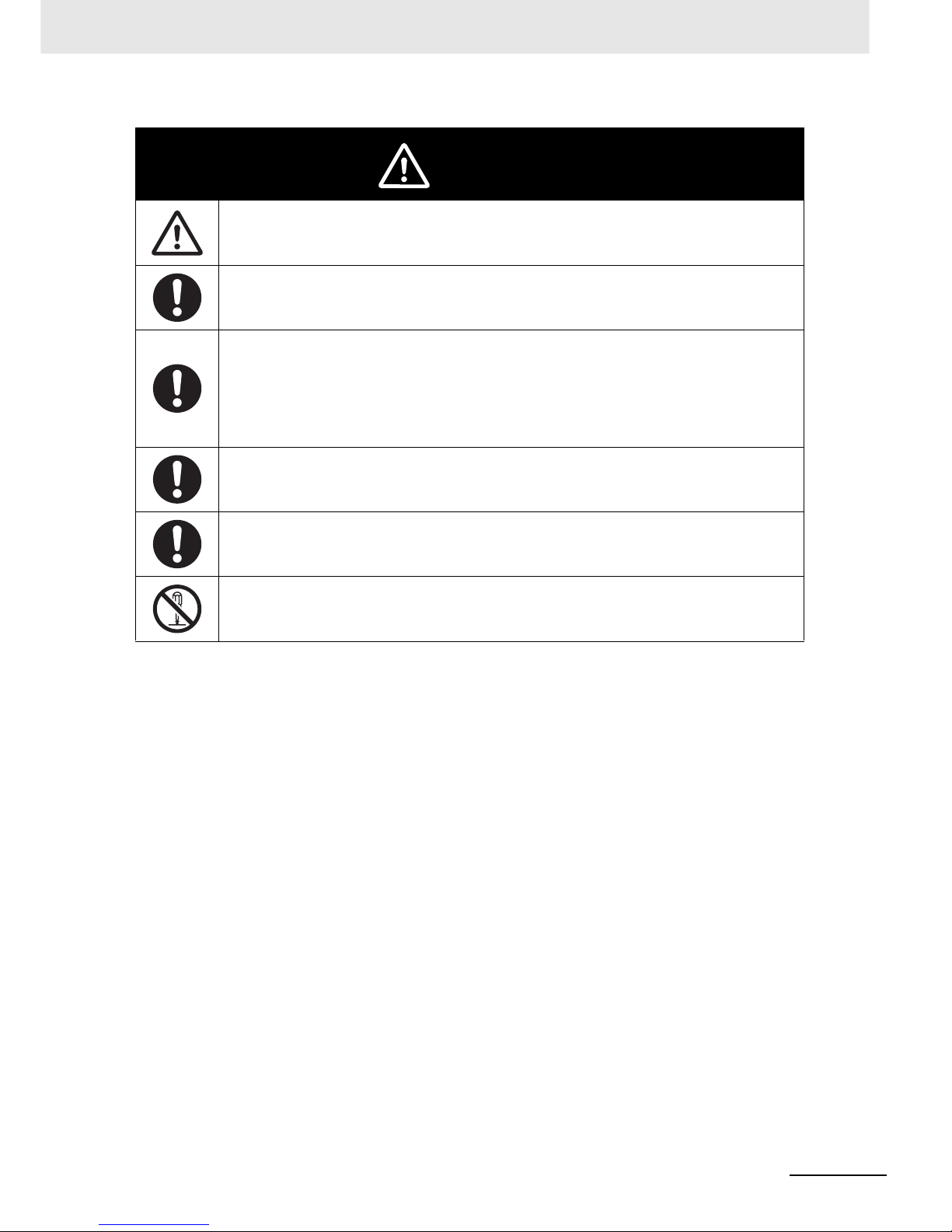
CAUTION
Do not connect resistors to the terminals (+1, P/+2, N/–) directly. Doing so might result in a
small-scale fire, heat generation, or damage to the unit.
Install a stop motion device to ensure safety.
Not doing so might result in a minor injury.
* A holding brake is not a stop motion device designed to ensure safety.
Be sure to use a specified type of braking resistor/regenerative braking unit. In case of a braking
resistor, install a thermal relay that monitors the temperature of the resistor. Not doing so might
result in a moderate burn due to the heat generated in the braking resistor/regenerative braking
unit.
Configure a sequence that enables the inverter power to turn off when unusual over eating is
detected in the braking resistor/regenerative braking unit.
The inverter has high voltage parts inside which, if short-circuited, might cause damage to itself or
other property. Place covers on the openings or take other precautions to make sure that no metal
objects such as cutting bits or lead wire scraps go inside when installing and wiring.
Take safety precautions such as setting up a molded-case circuit breaker (MCCB) that matches the
inverter capacity on the power supply side.
Not doing so might result in damage to property due to the short circuit of the load.
Do not dismantle, repair or modify the product.
Doing so may result in an injury.
Page 14

Precautions for Safe Use
12
Multi-function Compact Inverter 3G3MX2-V1 User’s Manual (I585-E1)
Precautions for Safe Use
Do not store or use the product in the following places.
• Locations subject to direct sunlight.
• Locations subject to ambient temperature exceeding the specifications.
• Locations subject to relative humidity exceeding the specifications.
• Locations subject to condensation due to severe temperature fluctuations.
• Locations subject to corrosive or flammable gases.
• Locations subject to exposure to combustibles.
• Locations subject to dust (especially iron dust) or salts.
• Locations subject to exposure to water, oil, or chemicals.
• Locations subject to direct shock or vibration.
• Do not drop or apply strong impact on the product. Doing so may result in damaged parts or malfunction.
• Do not hold by the front cover and terminal cover, but hold by the cooling fins during transportation.
• Confirm that the rated input voltage of the inverter is the same as AC power supply voltage.
• Do not connect an AC power supply voltage to the control input/output terminals. Doing so may result
in damage to the product.
• Be sure to tighten the screws on the terminal block securely. Wiring work must be done after installing the unit body.
• Do not connect any load other than a three-phase inductive motor to the U, V, and W output terminals.
• Take sufficient shielding measures when using the product in the following locations. Not doing so
may result in damage to the product.
Locations subject to static electricity or other forms of noise.
Locations subject to strong magnetic fields.
Locations close to power lines.
• If a parameter is set incorrectly when starting up, adjusting, maintaining, or replacing, an unexpected
operation may occur. Perform the operation after enough confirmation.
• When using the DriveProgramming, check that program is downloaded normally before starting operation.
• Be sure to confirm the permissible range of motors and machines before operation because the
inverter speed can be changed easily from low to high.
• Provide a separate holding brake if necessary.
• If the DriveProgramming stops during multi-function output, the output status is held. Take safety precautions such as stopping peripheral devices.
• Even when the inverter power is turned off, the counter-electromotive force occurs while the PM
motor rotates, which may result in electric shock.
Do not remove the terminal block cover of the inverter until the PM motor stops.
• Be sure to confirm the RUN signal is turned off before resetting the alarm because the machine may
abruptly start.
Installation and Storage
Transportation, Installation, and Wiring
Operation and Adjustment
Page 15

13
Precautions for Safe Use
Multi-function Compact Inverter 3G3MX2-V1 User’s Manual (I585-E1)
• Be sure to confirm safety before conducting maintenance, inspection or parts replacement.
• The capacitor service life is influenced by the ambient temperature. Refer to “Smoothing Capacitor
Life Curve” described in the manual. When a capacitor reaches the end of its service life and does
not work as the product, you need to replace the capacitor.
Maintenance and Inspection
Page 16

Precautions for Correct Use
14
Multi-function Compact Inverter 3G3MX2-V1 User’s Manual (I585-E1)
Precautions for Correct Use
Mount the product vertically on a wall with the product’s longer sides upright.
The material of the wall must be noninflammable such as a metal plate.
• Do not come close to the machine when using the restart selection function (b001, b008) because
the machine may abruptly start when stopped by an alarm.
Do not come close to the machine when selecting reset in Deceleration Stop Selection on Power Interruption (b050) because the machine may abruptly start after the power is turned on.
• Provide a separate emergency stop switch because the STOP Key on the Operator is valid only
when function settings are performed.
• When checking a signal during the power supply and the voltage is erroneously applied to the control
input terminals, the motor may start abruptly. Be sure to confirm safety before checking a signal.
• For the motor overload protection, be sure to set the rated current of your motor to the Electronic
Thermal Level (b012/b212) and PM Motor Rated Current (H105).
• Inverters contain components and will operate properly only when each component operates normally. Some of the electrical components require maintenance depending on application conditions.
Periodic inspection and replacement are necessary to ensure proper long-term operation of inverters. (Quoted from The Recommendation for Periodic Maintenance of a General-purpose Inverter
published by JEMA.)
• When a cooling fan reaches the end of its service life, replace it.
Comply with the local ordinance and regulations when disposing of the product.
Installation
Restart Selection Function
Deceleration Stop Function
Operation Stop Command
Motor Overload Protection
Maintenance and Parts Replacement
Product Disposal
Page 17
15
Precautions for Correct Use
Multi-function Compact Inverter 3G3MX2-V1 User’s Manual (I585-E1)
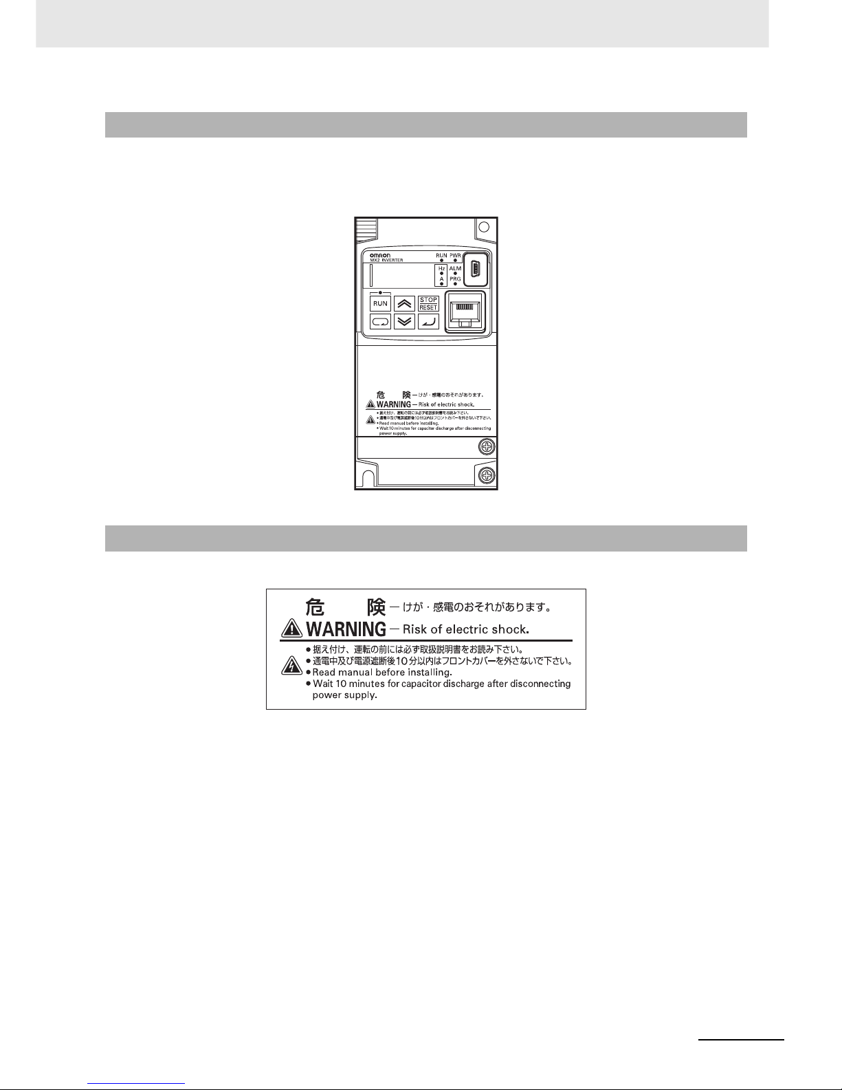
• This product bears a warning label at the following location to provide handling warnings.
• Be sure to follow the instructions.
The appearance differs depending on the capacity of the inverter.
Warning Label
Warning Description
Page 18

Regulations and Standards
16
Multi-function Compact Inverter 3G3MX2-V1 User’s Manual (I585-E1)
Regulations and Standards
To export (or provide to nonresident aliens) any part of this product that falls under the category of
goods (or technologies) for which an export certificate or license is mandatory according to the Foreign
Exchange and Foreign Trade Control Law of Japan, an export certificate or license (or service transaction approval) according to this law is required.
The 3G3MX2-V1 Series complies as standard with both the EC Directives and UL/cUL Standards.
EC Directives and UL/cUL Standards
Standard
Applicable standard
EC Directives EMC Directive EN61800-3: 2004
Low-voltage Directive EN61800-5-1: 2007
UL/cUL Standards UL 508C
Page 19

17
Trademarks
Multi-function Compact Inverter 3G3MX2-V1 User’s Manual (I585-E1)
Trademarks
• Windows, Windows 98, Windows XP, Windows Vista, and Windows 7 are registered trademarks of
Microsoft Corporation in the USA and other countries.
• EtherCAT® is registered trademark and patented technology, licensed by Beckhoff Automation
GmbH, Germany.
• DeviceNet is a registered trademark of ODVA (Open DeviceNet Vendor Association).
• CompoNet is a registered trademark of ODVA (Open DeviceNet Vendor Association).
• Other company names and product names in this document are the trademarks or registered trademarks of their respective companies.
Page 20
Items to Check after Unpacking
18
Multi-function Compact Inverter 3G3MX2-V1 User’s Manual (I585-E1)
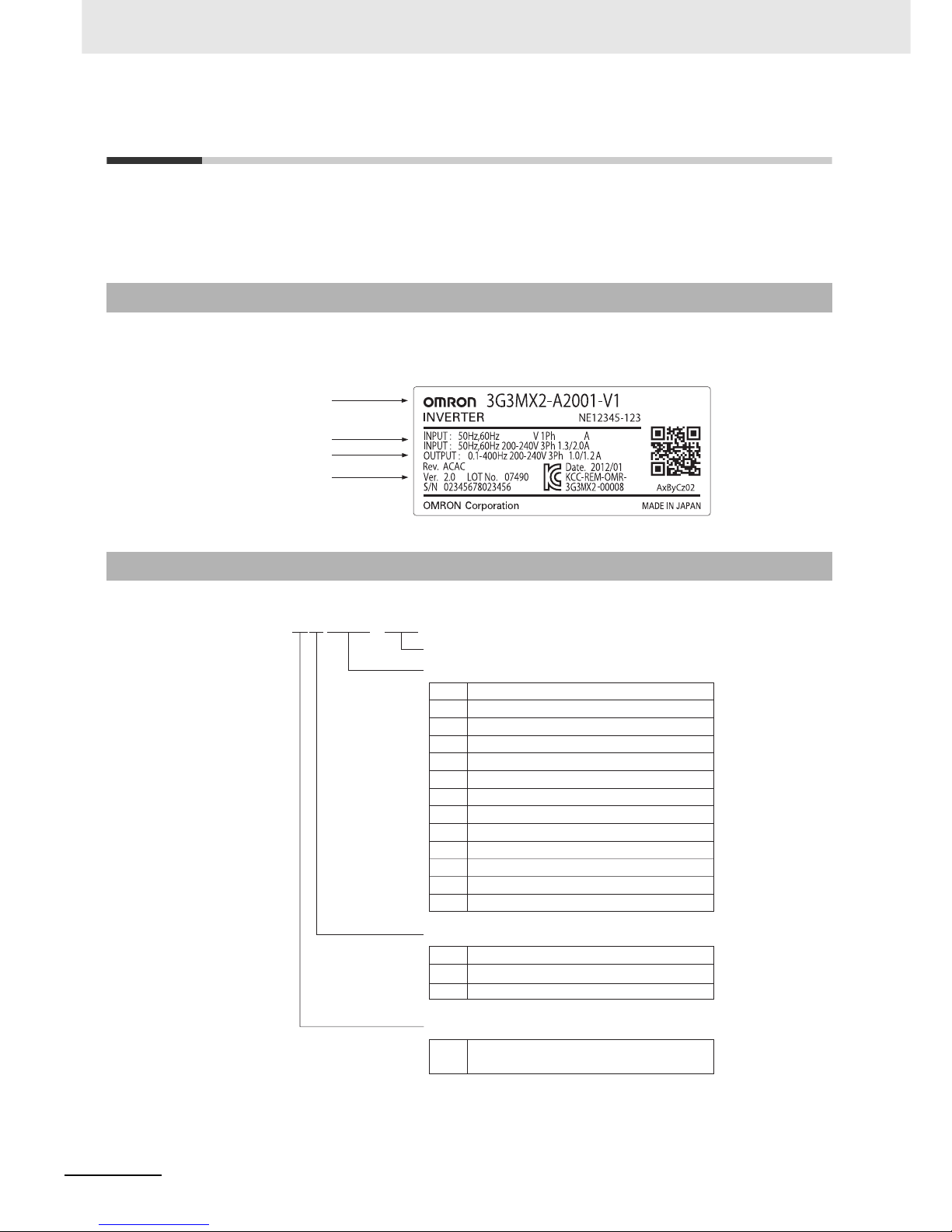
Items to Check after Unpacking
After unpacking, check the following items.
• Is this the model you ordered?
• Was there any damage sustained during shipment?
The nameplate is affixed to the product.
Checking the Nameplate
Checking the Model
Inverter model
Input specifications
Output specifications
Unit version
3G3MX2-A2055-V1
Maximum applicable motor capacity (CT rating)
Type V1
004
007
015
022
0.4 kW
0.75 kW
1.5 kW
2.2 kW
5.5 kW
7.5 kW
11 kW
15 kW
Voltage class
B
2
4
Single phase 200 VAC (200-V class)
3-phase 200 VAC (200-V class)
3-phase 400 VAC (400-V class)
Enclosure rating
A
Panel-mounting (IP10 or higher) or
closed wall-mounting models
0.1 kW
0.2 kW
001
3.0 kW
3.7 kW
4.0 kW
030
037
040
002
055
075
110
150
Page 21

19
Items to Check after Unpacking
Multi-function Compact Inverter 3G3MX2-V1 User’s Manual (I585-E1)
The instruction manual is the only accessory included in the Multi-function Compact Inverter (Model:
3G3MX2--V1).
Mounting screws and other necessary parts must be provided by the user.
Checking the Accessories
Page 22

Related Manuals
20
Multi-function Compact Inverter 3G3MX2-V1 User’s Manual (I585-E1)
Related Manuals
Please see the manuals below for related product information.
Name Catalog No.
CX-Drive Operation Manual W453
DriveProgramming User’s Manual I580
Regenerative Braking Unit 3G3AX-RBU User’s Manual I563
MX2/RX Series EtherCAT Communication Unit User's Manual I574
MX2/RX Series CompoNet Communications Unit User’s Manual I582
MX2/RX Series DeviceNet Communications Unit User’s Manual I581
Page 23
21
Revision History
Multi-function Compact Inverter 3G3MX2-V1 User’s Manual (I585-E1)
Revision History
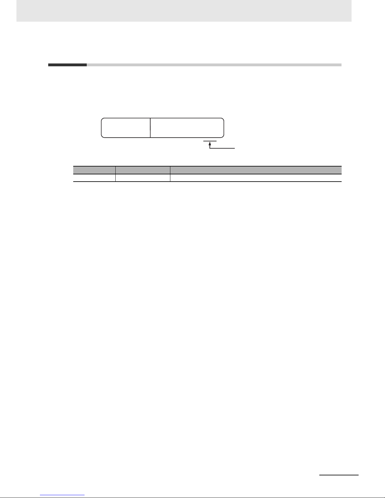
The manual revision code is a number appended to the end of the catalog number found in the bottom
right-hand corner of the front and back covers.
Revision code Revision date Revised Content
01 May 2013 Original production
Cat.No.
I585-E1-01
Example
Revision code
Page 24

CONTENTS
21
Multi-function Compact Inverter 3G3MX2-V1 User’s Manual (I585-E1)
CONTENTS
Introduction ..............................................................................................................1
Manual Configuration ..............................................................................................2
Manual Structure ......................................................................................................3
Sections in this Manual ...........................................................................................5
Terms and Conditions Agreement..........................................................................6
Safety Precautions ...................................................................................................8
Precautions for Safe Use.......................................................................................12
Precautions for Correct Use.................................................................................. 14
Regulations and Standards...................................................................................16
Trademarks .............................................................................................................17
Items to Check after Unpacking............................................................................18
Related Manuals .....................................................................................................20
Revision History .....................................................................................................21
CONTENTS..............................................................................................................21
Section 1 Overview
1-1 Overview of Functions .......................................................................................................... 1-2
1-1-1 Features of 3G3MX2-V1 Series Inverter.....................................................................................1-2
1-1-2 Classes of 3G3MX2-V1 Series Inverter ......................................................................................1-6
1-1-3 Compliance with International Standards (EC Directives and UL/cUL Standards) .....................1-7
1-2 Appearance and Part Names ................................................................................................ 1-8
1-3 Specifications ...................................................................................................................... 1-12
1-3-1 Standard Specifications.............................................................................................................1-12
1-3-2 External Dimensions .................................................................................................................1-17
1-4 Restrictions .......................................................................................................................... 1-23
1-5 Comparison with Previous Model ...................................................................................... 1-25
Section 2 Design
2-1 Installation.............................................................................................................................. 2-4
2-1-1 Inverter Installation......................................................................................................................2-4
2-1-2 Installation Environment..............................................................................................................2-4
2-2 Removal of Each Part............................................................................................................ 2-7
2-2-1 Removing Covers........................................................................................................................2-7
2-2-2 Terminal Blocks...........................................................................................................................2-8
2-2-3 Preparing Backing Plate..............................................................................................................2-9
2-3 Wiring ................................................................................................................................... 2-10
Page 25

22
CONTENTS
Multi-function Compact Inverter 3G3MX2-V1 User’s Manual (I585-E1)
2-3-1 Standard Connection Diagram.................................................................................................. 2-10
2-3-2 Arrangement and Function of Main Circuit Terminal Block........................................................2-11
2-3-3 Arrangement and Function of Control Circuit Terminal Block................................................... 2-12
2-3-4 Wiring for Main Circuit Terminals.............................................................................................. 2-15
2-3-5 Wiring for Control Circuit Terminals.......................................................................................... 2-33
2-3-6 Wiring for RS485 Communications Terminals .......................................................................... 2-40
2-3-7 Wiring for Digital Operator ........................................................................................................ 2-42
2-3-8 Safety Function (Under Application for Standards)................................................................... 2-43
2-3-9 Compliance with EC Directives................................................................................................. 2-44
Section 3 Operation and Test Run
3-1 Operation of Digital Operator ............................................................................................... 3-4
3-1-1 Part Names and Descriptions..................................................................................................... 3-4
3-1-2 Key Operation Method................................................................................................................ 3-6
3-2 Connections and Functions of CX-Drive........................................................................... 3-13
3-2-1 CX-Drive Connection Method................................................................................................... 3-13
3-2-2 Overview of CX-Drive Functions............................................................................................... 3-17
3-3 Flow of Test Run.................................................................................................................. 3-21
3-4 Operation Items for Test Run ............................................................................................. 3-22
Section 4 Parameter List
4-1 Monitor Mode ......................................................................................................................... 4-2
4-1-1 Group d....................................................................................................................................... 4-2
4-2 Function Mode ....................................................................................................................... 4-5
4-2-1 Group F: Basic Function Parameters .........................................................................................4-5
4-3 Extended Function Mode ...................................................................................................... 4-6
4-3-1 Group A: Standard Function Parameters.................................................................................... 4-7
4-3-2 Group b: Detailed Function Parameters ................................................................................... 4-14
4-3-3 Group C: Multi-function Terminal Function Parameters............................................................ 4-24
4-3-4 Group H: Motor Control Parameters......................................................................................... 4-32
4-3-5 Group P: Option/Applied Function Parameters ........................................................................ 4-35
4-3-6 Group U: User Parameters....................................................................................................... 4-41
Section 5 Basic Settings
5-1 Parameter Display and Parameter Initialization ................................................................. 5-3
5-1-1 Display Selection ........................................................................................................................ 5-3
5-1-2 Parameter Initialization ............................................................................................................... 5-6
5-2 V/f Control Settings ............................................................................................................... 5-9
5-2-1 Control Method (V/f Characteristics)........................................................................................... 5-9
5-2-2 Heavy Load/Light Load Selection............................................................................................. 5-12
5-3 Motor Parameter Settings ................................................................................................... 5-16
5-3-1 Motor Capacity/Pole Number Selection.................................................................................... 5-16
5-3-2 Electronic Thermal Function..................................................................................................... 5-16
5-3-3 Base Frequency and Maximum Frequency of Motor................................................................ 5-21
5-4 RUN Command Settings ..................................................................................................... 5-22
5-4-1 RUN Command Selection......................................................................................................... 5-22
5-5 Frequency Reference Settings ........................................................................................... 5-24
5-5-1 Frequency Reference Selection ............................................................................................... 5-24
5-5-2 Frequency Reference Correlation Chart................................................................................... 5-30
5-5-3 Frequency Limit ........................................................................................................................ 5-31
5-6 Acceleration/Deceleration Time Settings .......................................................................... 5-33
Page 26

CONTENTS
23
Multi-function Compact Inverter 3G3MX2-V1 User’s Manual (I585-E1)
5-6-1 Acceleration/Deceleration Time Settings ..................................................................................5-33
5-6-2 Acceleration/Deceleration Pattern.............................................................................................5-34
5-6-3 2-step Acceleration/Deceleration Function ...............................................................................5-37
5-7 Stop Method Settings.......................................................................................................... 5-39
5-7-1 Stop Selection...........................................................................................................................5-39
5-7-2 Free-run Stop Selection ............................................................................................................5-39
5-7-3 STOP Key Selection .................................................................................................................5-42
5-8 Reset Method Settings ........................................................................................................5-43
5-8-1 Reset.........................................................................................................................................5-43
5-8-2 Restart after Resetting ..............................................................................................................5-45
5-9 Multi-function Input Settings .............................................................................................. 5-47
5-9-1 Multi-function Input Selection....................................................................................................5-47
5-9-2 Multi-function Input Operation Selection...................................................................................5-48
5-9-3 Input Terminal Response Time .................................................................................................5-48
5-9-4 Forward RUN Command (FW) and Reverse RUN Command (RV) .........................................5-48
5-9-5 Multi-step Speed Operation Function........................................................................................5-49
5-9-6 Jogging (JG)..............................................................................................................................5-52
5-9-7 2-step Acceleration/Deceleration (2CH)....................................................................................5-53
5-9-8 Reset (RS) ................................................................................................................................5-53
5-9-9 3-wire Input Function (STA, STP, F/R) ......................................................................................5-54
5-10 Multi-function Output Settings........................................................................................... 5-55
5-10-1 Multi-function Output Selection .................................................................................................5-55
5-10-2 Multi-function Output Operation Selection ................................................................................5-55
5-10-3 Multi-function Output ON/OFF Delay Time ...............................................................................5-56
5-10-4 Signal during RUN (RUN) .........................................................................................................5-56
5-10-5 Constant Speed Arrival Signal (FA1).........................................................................................5-57
5-10-6 Alarm Signal (AL)......................................................................................................................5-57
5-10-7 0-Hz Detection Signal (ZS) .......................................................................................................5-58
5-10-8 Operation Ready (IRDY)...........................................................................................................5-59
5-10-9 Forward Run Signal (FWR).......................................................................................................5-59
5-10-10 Reverse Run Signal (RVR) .......................................................................................................5-59
5-11 Torque Boost Function Settings ........................................................................................ 5-60
5-11-1 Torque Boost.............................................................................................................................5-60
5-12 Measures against Overvoltage........................................................................................... 5-63
5-12-1 Overvoltage Suppression Function during Deceleration...........................................................5-63
5-12-2 Regenerative Braking Function.................................................................................................5-65
Section 6 Vector Control and Applied Functions
6-1 Sensorless Vector Control....................................................................................................6-3
6-1-1 Sensorless Vector Control Parameter Settings...........................................................................6-3
6-1-2 Offline Auto-tuning for Motor Parameters ...................................................................................6-4
6-1-3 Motor Parameter Settings ...........................................................................................................6-9
6-1-4 Adjustments for Sensorless Vector Control...............................................................................6-10
6-2 Torque Limit Function......................................................................................................... 6-12
6-2-1 Torque Limit Function Settings..................................................................................................6-12
6-2-2 Torque LADSTOP Function Settings.........................................................................................6-14
6-3 Overtorque/Undertorque Function .................................................................................... 6-15
6-3-1 Overtorque/Undertorque Function Settings ..............................................................................6-15
6-4 Torque Control..................................................................................................................... 6-16
6-4-1 Torque Control Settings.............................................................................................................6-16
6-4-2 Torque Bias Function Settings ..................................................................................................6-17
6-5 V/f Control with Speed Feedback....................................................................................... 6-18
6-5-1 Settings of V/f Control with Speed Feedback............................................................................6-18
6-5-2 Recommended Encoder and Its Wiring ....................................................................................6-19
6-5-3 Protective Detection under V/f Control with Speed Feedback ..................................................6-23
6-5-4 Adjustments for V/f Control with Speed Feedback....................................................................6-24
Page 27

24
CONTENTS
Multi-function Compact Inverter 3G3MX2-V1 User’s Manual (I585-E1)
6-6 Brake Control Function.......................................................................................................6-25
6-6-1 Operation Sequence of Brake Control Function ....................................................................... 6-25
6-6-2 Brake Control Function Settings............................................................................................... 6-26
6-7 Simple Position Control ......................................................................................................6-28
6-7-1 Feedback Settings for Simple Position Control ........................................................................ 6-28
6-7-2 Recommended Encoder for Simple Position Control and Its Wiring ........................................ 6-29
6-7-3 Simple Position Control Operation and Settings....................................................................... 6-34
6-7-4 Origin Search Function, Current Position Preset, Position Data Storage at Power Shutoff ..... 6-40
6-7-5 Restarting Positioning............................................................................................................... 6-45
6-7-6 Multi-step Position Control Settings.......................................................................................... 6-45
6-7-7 Turntable Control...................................................................................................................... 6-47
6-7-8 Speed/Position Switching ......................................................................................................... 6-48
6-7-9 Interlock Function with Simple Position Control and Brake Control.......................................... 6-49
6-8 PM Motor Mode .................................................................................................................... 6-53
6-8-1 PM Motor and PM Motor Control..............................................................................................6-53
6-8-2 Functional Limitations in PM Motor Mode................................................................................. 6-55
6-8-3 Switching to PM Motor Mode.................................................................................................... 6-57
6-8-4 Offline Auto-tuning for PM Motor Parameters........................................................................... 6-57
6-8-5 PM Motor Parameter Settings .................................................................................................. 6-61
6-8-6 Adjustment of PM Motor Mode Settings ................................................................................... 6-63
Section 7 Other Functions
7-1 Monitor Mode ......................................................................................................................... 7-4
7-1-1 Output Frequency Monitor [d001] ............................................................................................... 7-4
7-1-2 Output Current Monitor [d002].................................................................................................... 7-4
7-1-3 RUN Direction Monitor [d003]..................................................................................................... 7-5
7-1-4 PID Feedback Value Monitor [d004]........................................................................................... 7-5
7-1-5 Multi-function Input Monitor [d005] ............................................................................................. 7-5
7-1-6 Multi-function Output Monitor [d006]........................................................................................... 7-6
7-1-7 Output Frequency Monitor (After Conversion) [d007]................................................................. 7-6
7-1-8 Real Frequency Monitor [d008] .................................................................................................. 7-7
7-1-9 Torque Reference Monitor [d009] ............................................................................................... 7-7
7-1-10 Torque Bias Monitor [d010]......................................................................................................... 7-8
7-1-11 Output Torque Monitor [d012]..................................................................................................... 7-8
7-1-12 Output Voltage Monitor [d013].................................................................................................... 7-8
7-1-13 Input Power Monitor [d014]......................................................................................................... 7-9
7-1-14 Integrated Power Monitor [d015] ................................................................................................ 7-9
7-1-15 Total RUN Time Monitor [d016]................................................................................................. 7-10
7-1-16 Total Power ON Time Monitor [d017]........................................................................................7-10
7-1-17 Fin Temperature Monitor [d018]................................................................................................ 7-10
7-1-18 Life Assessment Monitor [d022] ................................................................................................7-11
7-1-19 Program Counter (DriveProgramming) [d023]...........................................................................7-11
7-1-20 User Monitor 0 to 2 (DriveProgramming) [d025 to d027]
....
.......................................................7-11
7-1-21 Position Command Monitor [d029] ...........................................................................................7-12
7-1-22 Current Position Monitor [d030] ................................................................................................ 7-12
7-1-23 Dual User Monitor [d050].......................................................................................................... 7-13
7-1-24 Inverter Mode Monitor [d060].................................................................................................... 7-13
7-1-25 Frequency Reference Source Monitor [d062]........................................................................... 7-14
7-1-26 Run Command Source Monitor [d063]..................................................................................... 7-14
7-1-27 Fault Counter [d080]................................................................................................................. 7-14
7-1-28 Fault Monitor 1 to 6 [d081 to 086]............................................................................................. 7-15
7-1-29 Warning Monitor [d090] ............................................................................................................ 7-15
7-1-30 DC Voltage Monitor [d102]........................................................................................................ 7-15
7-1-31 Regenerative Braking Load Rate Monitor [d103]...................................................................... 7-16
7-1-32 Electronic Thermal Load Rate Monitor [d104] .......................................................................... 7-16
7-1-33 Analog Voltage Input FV Monitor [d130]................................................................................... 7-16
7-1-34 Analog Current Input FI Monitor [d131] ....................................................................................7-16
7-1-35 Pulse Train Input RP Monitor [d133]......................................................................................... 7-17
7-1-36 PID Deviation [d153]................................................................................................................. 7-17
7-1-37 PID Output Monitor [d155]........................................................................................................ 7-17
Page 28

CONTENTS
25
Multi-function Compact Inverter 3G3MX2-V1 User’s Manual (I585-E1)
7-2 Multi-function Input/Output Functions .............................................................................. 7-18
7-2-1 Multi-function Input Selection....................................................................................................7-18
7-2-2 Multi-function Output Selection.................................................................................................7-20
7-3 Analog I/O Settings ............................................................................................................. 7-22
7-3-1 Analog Input (FV, FI).................................................................................................................7-22
7-3-2 Analog Input Filter.....................................................................................................................7-24
7-3-3 Analog Command Hold Function (AHD) ...................................................................................7-24
7-3-4 Analog Input Adjustment...........................................................................................................7-25
7-3-5 Analog Input Start/End Function Settings ................................................................................. 7-25
7-3-6 Terminal MP (Pulse/PWM Output)............................................................................................7-27
7-3-7 Terminal AM (Analog Output)....................................................................................................7-29
7-4 Inverter Control Settings ....................................................................................................7-31
7-4-1 Carrier Frequency .....................................................................................................................7-31
7-4-2 Automatic Carrier Reduction.....................................................................................................7-32
7-4-3 2nd Control Function (SET) ......................................................................................................7-33
7-5 Other Operation Functions ................................................................................................. 7-35
7-5-1 Starting Frequency....................................................................................................................7-35
7-5-2 Reduced Voltage Startup Selection...........................................................................................7-36
7-5-3 Frequency Jump Function.........................................................................................................7-36
7-5-4 Acceleration/Deceleration Stop Function..................................................................................7-37
7-5-5 RUN Direction Limit Selection...................................................................................................7-38
7-5-6 Permission of RUN Command..................................................................................................7-38
7-5-7 Frequency Calculation Function................................................................................................7-39
7-5-8 Frequency Addition Function ....................................................................................................7-39
7-5-9 Remote Operation Function (UP/DWN)....................................................................................7-40
7-5-10 Output Voltage Gain..................................................................................................................7-41
7-5-11 AVR (Automatic Voltage Regulator) Function ...........................................................................7-42
7-5-12 PID Function .............................................................................................................................7-44
7-5-13 Automatic Energy-saving Operation Function...........................................................................7-50
7-5-14 Commercial Switching (CS) ......................................................................................................7-50
7-5-15 Stabilization Parameter .............................................................................................................7-52
7-5-16 Pulse Train Frequency Input .....................................................................................................7-52
7-5-17 LAD Cancel Function ................................................................................................................7-53
7-6 Digital Operator and Operation Functions ........................................................................ 7-54
7-6-1 Soft Lock Function (SFT) ..........................................................................................................7-54
7-6-2 Forced Operator Function (OPE)..............................................................................................7-55
7-6-3 Forced Terminal Block Function (F-TM)....................................................................................7-55
7-6-4 Operation Selection at External Operator Disconnection..........................................................7-56
7-6-5 Initial Screen Selection (Initial Screen after Power-on).............................................................7-56
7-6-6 Initial Screen Automatic Return Function..................................................................................7-56
7-6-7 Inverter Display on Operator Connection..................................................................................7-57
7-6-8 Display Fixed (DISP).................................................................................................................7-57
7-6-9 Password Function....................................................................................................................7-57
7-6-10 User Parameter Setting Function..............................................................................................7-60
7-6-11 User Parameter Automatic Setting Function.............................................................................7-60
7-7 Restart Functions ................................................................................................................ 7-61
7-7-1 Frequency Matching Restart and Frequency Pull-in Restart ....................................................7-61
7-7-2 Restart during Power Interruption, Undervoltage/Overvoltage, Overcurrent ............................7-63
7-7-3 Power Recovery Restart Prevention Function (USP) ...............................................................7-67
7-7-4 Deceleration Stop on Power Interruption Function ...................................................................7-68
7-8 Functions Related to Protection, Warning, and Various Output Signals....................... 7-72
7-8-1 Free-electronic Thermal Function .............................................................................................7-72
7-8-2 Motor Electronic Thermal Function ...........................................................................................7-73
7-8-3 Electronic Thermal Warning......................................................................................................7-75
7-8-4 Overload Limit/Overload Warning ............................................................................................. 7-76
7-8-5 Overcurrent Suppression Function ...........................................................................................7-79
7-8-6 External Trip (EXT) ...................................................................................................................7-79
7-8-7 Thermistor Trip Function...........................................................................................................7-80
7-8-8 Signal during RUN (RUN) .........................................................................................................7-80
7-8-9 Frequency Arrival Signal (FA2 to FA5)......................................................................................7-81
7-8-10 RUN Time/Power ON Time Over (RNT/ONT)...........................................................................7-82
Page 29

26
CONTENTS
Multi-function Compact Inverter 3G3MX2-V1 User’s Manual (I585-E1)
7-8-11 Logic Operation Output Signal (LOG1 to LOG3) ...................................................................... 7-83
7-8-12 Capacitor Life Warning Signal (WAC).......................................................................................7-84
7-8-13 Cooling Fan Operation.............................................................................................................. 7-84
7-8-14 Cooling Fan Life Warning Signal (WAF)................................................................................... 7-85
7-8-15 Communication Disconnection Detection Signal (NDc)............................................................ 7-85
7-8-16 Starting Contact Signal (FR)..................................................................................................... 7-86
7-8-17 Cooling Fin Overheat Warning (OHF) ...................................................................................... 7-86
7-8-18 Low Current Signal (LOC) ........................................................................................................ 7-87
7-8-19 Fatal Fault Signal (MJA)........................................................................................................... 7-87
7-8-20 Window Comparator (WCFV/WCFI) (Disconnection Detection FVDc/FIDc) ............................ 7-88
7-8-21 Frequency Reference Selection Status Signal (FREF)............................................................. 7-89
7-8-22 RUN Command Status Signal (REF)........................................................................................ 7-89
7-8-23 2nd Control Selection Signal (SETM).......................................................................................7-90
7-9 DC Injection Braking Function ........................................................................................... 7-91
7-9-1 DC Injection Braking (DB)......................................................................................................... 7-91
7-10 Safety Function (Under Application for Standards)......................................................... 7-97
7-10-1 Overview of Safety Function..................................................................................................... 7-97
7-10-2 Safety Function Settings........................................................................................................... 7-97
7-10-3 Wiring Safety Function for Use ................................................................................................. 7-98
7-10-4 Wiring Example......................................................................................................................... 7-99
7-11 Option/Applied Functions (Group P) ............................................................................... 7-101
7-11-1 Operation Selection on Option Error....................................................................................... 7-101
7-11-2 Communications Option Function........................................................................................... 7-101
7-11-3 DriveProgramming Function Parameters ............................................................................... 7-102
Section 8 Communications Functions
8-1 Communications Specifications .......................................................................................... 8-3
8-2 RS485 Terminal Arrangement and Connection .................................................................. 8-4
8-3 Modbus Communication Parameters .................................................................................. 8-5
8-4 Modbus Communication Protocol ....................................................................................... 8-7
8-4-1 Message Configuration............................................................................................................... 8-7
8-4-2 Required Communications Time ................................................................................................ 8-9
8-4-3 Normal Response....................................................................................................................... 8-9
8-4-4 Abnormal Response ................................................................................................................... 8-9
8-4-5 No Response............................................................................................................................ 8-10
8-5 Explanation of Each Function Code .................................................................................. 8-11
8-5-1 Read Coil Status [01 hex]..........................................................................................................8-11
8-5-2 Read from Holding Register [03 hex]........................................................................................8-12
8-5-3 Write to Coil [05 hex] ................................................................................................................ 8-13
8-5-4 Write to Holding Register [06 hex]............................................................................................ 8-14
8-5-5 Loop-back Test [08 hex]............................................................................................................ 8-15
8-5-6 Write to Multiple Coils [0F hex]................................................................................................. 8-16
8-5-7 Write to Multiple Holding Registers [10 hex]............................................................................. 8-18
8-5-8 Read/Write from/to Multiple Holding Registers [17h]................................................................ 8-19
8-5-9 Exception Response................................................................................................................. 8-20
8-6 Saving a Change to Holding Register (Enter Command) ................................................ 8-21
8-6-1 How to Issue Enter Command.................................................................................................. 8-21
8-6-2 EEPROM Write Mode.............................................................................................................. 8-23
8-7 Modbus Mapping Function ................................................................................................. 8-24
8-7-1 Operation of Modbus Mapping Function................................................................................... 8-24
8-7-2 Modbus Mapping Function Settings ......................................................................................... 8-25
8-7-3 Compressed Single-word Registers ......................................................................................... 8-26
8-7-4 Troubleshooting for Modbus Mapping Function ....................................................................... 8-28
8-7-5 Endian Function........................................................................................................................ 8-29
8-8 Co-inverter Communication ............................................................................................... 8-31
8-8-1 Co-inverter Communication Parameters .................................................................................. 8-32
8-8-2 Co-inverter Communication Settings ........................................................................................ 8-35
Page 30

CONTENTS
27
Multi-function Compact Inverter 3G3MX2-V1 User’s Manual (I585-E1)
8-9 Modbus Communication Data Lists................................................................................... 8-37
8-9-1 Coil Number List........................................................................................................................8-37
8-9-2 Monitor Function/Enter Command Register List .......................................................................8-41
8-9-3 Group F Register List................................................................................................................8-50
8-9-4 Group A/b/C/H/P Register List ..................................................................................................8-51
8-9-5 2nd Control Register Number List.............................................................................................8-96
Section 9 Overview of DriveProgramming
9-1 Overview of DriveProgramming ........................................................................................... 9-2
Section 10 Troubleshooting
10-1 Alarm Display and Remedies ............................................................................................. 10-2
10-1-1 Alarm Display............................................................................................................................10-2
10-1-2 Alarm Code List.........................................................................................................................10-4
10-1-3 Option Unit Protective Function List........................................................................................10-10
10-1-4 Warning Display......................................................................................................................10-12
10-1-5 Other Indications on Digital Operator......................................................................................10-13
10-2 Troubleshooting ................................................................................................................ 10-14
Section 11 Maintenance and Inspection
11-1 Maintenance and Inspection .............................................................................................. 11-2
11-1-1 Daily Inspection......................................................................................................................... 11-3
11-1-2 Cleaning.................................................................................................................................... 11-3
11-1-3 Periodic Inspection.................................................................................................................... 11-3
11-1-4 Daily/Periodic Inspection Items................................................................................................. 11-4
11-1-5 Megger Test .............................................................................................................................. 11-7
11-1-6 Withstand Voltage Test.............................................................................................................. 11-7
11-1-7 Inverter/Converter Unit Test ...................................................................................................... 11-7
11-1-8 I/O Voltage/Current/Electric Power Measurement Method ....................................................... 11-9
Section 12 Options
12-1 Overview of Optional Equipment ....................................................................................... 12-3
12-1-1 Part Names and Descriptions ...................................................................................................12-3
12-2 Regenerative Braking Unit (Model: 3G3AX-RBU) ...................................................... 12-5
12-2-1 Specifications ............................................................................................................................12-5
12-2-2 External Dimensions ................................................................................................................. 12-7
12-2-3 Connection Examples ............................................................................................................. 12-11
12-3 Braking Resistor (Model: 3G3AX-RBA/RBB/RBC)............................................. 12-12
12-3-1 Specifications ..........................................................................................................................12-12
12-3-2 External Dimensions ...............................................................................................................12-13
12-3-3 Connection Examples .............................................................................................................12-15
12-4 Regenerative Braking Unit and Braking Resistor Combination Selection Table ........ 12-16
12-5 DC Reactor (Model: 3G3AX-DL) .......................................................................... 12-20
12-5-1 Specifications ..........................................................................................................................12-20
12-5-2 External Dimensions ...............................................................................................................12-22
12-5-3 Connection Examples .............................................................................................................12-24
12-6 AC Reactor (Model: 3G3AX-AL) .......................................................................... 12-25
12-6-1 Specifications ..........................................................................................................................12-25
12-6-2 External Dimensions ...............................................................................................................12-26
12-6-3 Connection Examples .............................................................................................................12-27
Page 31

28
CONTENTS
Multi-function Compact Inverter 3G3MX2-V1 User’s Manual (I585-E1)
12-7 Input Noise Filter (Model: 3G3AX-NFI) ...................................................................... 12-28
12-7-1 Specifications.......................................................................................................................... 12-28
12-7-2 External Dimensions............................................................................................................... 12-29
12-7-3 Connection Examples............................................................................................................. 12-33
12-8 Output Noise Filter (Model: 3G3AX-NFO) ................................................................. 12-34
12-8-1 Specifications.......................................................................................................................... 12-34
12-8-2 External Dimensions............................................................................................................... 12-35
12-8-3 Connection Examples............................................................................................................. 12-36
12-9 Radio Noise Filter (Model: 3G3AX-ZCL)....................................................................... 12-37
12-9-1 Specifications.......................................................................................................................... 12-37
12-9-2 External Dimensions............................................................................................................... 12-38
12-9-3 Connection Examples............................................................................................................. 12-38
12-10EMC Noise Filter ................................................................................................................ 12-39
12-10-1 Specifications.......................................................................................................................... 12-39
12-10-2 Connection Examples............................................................................................................. 12-40
12-11Digital Operator (Model: 3G3AX-OP01) ........................................................................... 12-41
12-11-1 Specifications.......................................................................................................................... 12-41
12-11-2 External Dimensions............................................................................................................... 12-42
12-12Digital Operator Cable (Model: 3G3AX-OPCN) ............................................................ 12-43
12-12-1 Specifications.......................................................................................................................... 12-43
12-12-2 External Dimensions............................................................................................................... 12-43
12-13EtherCAT Communications Unit (Model: 3G3AX-MX2-ECT) ......................................... 12-44
12-13-1 Specifications.......................................................................................................................... 12-44
12-13-2 External Dimensions............................................................................................................... 12-45
12-14CompoNet Communications Unit (Model: 3G3AX-MX2-CRT-E).................................... 12-46
12-14-1 Specifications.......................................................................................................................... 12-46
12-14-2 External Dimensions............................................................................................................... 12-47
12-15DeviceNet Communications Unit (Model: 3G3AX-MX2-DRT-E)..................................... 12-48
12-15-1 Specifications.......................................................................................................................... 12-48
12-15-2 External Dimensions............................................................................................................... 12-49
Appendices
A-1 Derating ..................................................................................................................................A-2
A-2 Smoothing Capacitor Life Curve..........................................................................................A-8
A-3 Life Alarm Output ..................................................................................................................A-9
A-4 UL/cUL Standards Cautions ...............................................................................................A-10
A-5 Overview of Inverter Selection ...........................................................................................A-12
Index
Page 32

CONTENTS
29
Multi-function Compact Inverter 3G3MX2-V1 User’s Manual (I585-E1)
Page 33

1 - 1
Multi-function Compact Inverter 3G3MX2-V1 User’s Manual (I585-E1)
1
This section provides an overview of the 3G3MX2-V1 Series features, standard specifications, and external dimensions by inverter capacity. It also shows the differences of
this inverter from the conventional inverter for those who use the previous model.
1-1 Overview of Functions . . . . . . . . . . . . . . . . . . . . . . . . . . . . . . . . . . . . . . . . . . 1-2
1-1-1 Features of 3G3MX2-V1 Series Inverter . . . . . . . . . . . . . . . . . . . . . . . . . . . . . 1-2
1-1-2 Classes of 3G3MX2-V1 Series Inverter . . . . . . . . . . . . . . . . . . . . . . . . . . . . . . 1-6
1-1-3 Compliance with International Standards
(EC Directives and UL/cUL Standards) . . . . . . . . . . . . . . . . . . . . . . . . . . . . . . . 1-7
1-2 Appearance and Part Names . . . . . . . . . . . . . . . . . . . . . . . . . . . . . . . . . . . . 1-8
1-3 Specifications . . . . . . . . . . . . . . . . . . . . . . . . . . . . . . . . . . . . . . . . . . . . . . . . 1-12
1-3-1 Standard Specifications . . . . . . . . . . . . . . . . . . . . . . . . . . . . . . . . . . . . . . . . . 1-12
1-3-2 External Dimensions . . . . . . . . . . . . . . . . . . . . . . . . . . . . . . . . . . . . . . . . . . . . 1-17
1-4 Restrictions . . . . . . . . . . . . . . . . . . . . . . . . . . . . . . . . . . . . . . . . . . . . . . . . . 1-23
1-5 Comparison with Previous Model . . . . . . . . . . . . . . . . . . . . . . . . . . . . . . . 1-25
Overview
Page 34

1 Overview
1 - 2
Multi-function Compact Inverter 3G3MX2-V1 User’s Manual (I585-E1)
1-1 Overview of Functions
The Multi-function Compact Inverter (Model: 3G3MX2--V1) provides a variety of functions such as
PM motor control and simple position control. It is also designed for open field networks to extend application usability.
In addition, the 3G3MX2-V1 Series complies as standard with both the EC Directives and UL/cUL Standards. You can use this product as a world standard inverter.
The 3G3MX2-V1 Series Inverter has the following features.
Although this inverter is compact, it provides high functionality for enhanced application support and
addresses diverse needs with optimal performance.
z PM motors
In addition to conventional induction motors, this inverter provides the PM motor mode that supports
highly efficient PM motors, which results in more efficient control than the conventional energysaving control.
This is combined with the OMRON’s unique auto-tuning function and initial pole position estimation
function that estimates the magnetic pole position of a PM motor during startup to enable its smooth
start.
This control is suitable for applications with reduced torque characteristics (which do not require
torque at low speeds) such as fans and pumps.
However, it cannot be used for applications with constant torque characteristics such as general
transfer equipment and elevating axes, where the starting torque exceeds 50% of the rated motor
torque.
z Implementation of the dual rating function
This inverter has the dual rating function that consists of the heavy load mode and the light load
mode.
This enables the efficient utilization of the inverter depending on your application.
• Heavy load mode
The heavy load mode is used for a transfer machine, elevator, or other device that temporarily
requires a torque exceeding the rated torque. This mode enables high torque control similar to
that achieved with the previous product.
The overload capacity is 150% of the rated current for 1 minute.
• Light load mode
The light load mode is used for a fan, pump, or other device that operates at the rated motor
torque or lower.
Setting the light load mode causes the rated current of the inverter to increase, enabling the
inverter to drive a motor whose capacity is one size larger.
However, check when selecting an inverter because this also decreases the current overload
capacity to 120% of the rated current for 1 minute.
1-1-1 Features of 3G3MX2-V1 Series Inverter
Enhanced Application Support
Page 35

1 - 3
1 Overview
Multi-function Compact Inverter 3G3MX2-V1 User’s Manual (I585-E1)
1-1 Overview of Functions
1
1-1-1 Features of 3G3MX2-V1 Series Inverter
Precautions for Correct Use
Derating of the rated output current of the inverter may be required depending on the
heavy/light load mode selection, operating ambient temperature, side-by-side installation, and
carrier frequency settings.
Use the inverter in an appropriate environment according to A-1 Derating on page A-2.
z Simple position control
This inverter provides simple position control that enables the control of up to 8 points with a single
inverter unit.
With the standard pulse train input function, it realizes accurate position control based on the feedback of the pulse generator (PG) signal or the encoder’s phase-A/B signal.
For enhancements, simple position control has the following additional functions this time. Moreover, it can be combined with control from the open field network to expand the control range of your
system.
z Implementation of the programming function
The 3G3MX2-V1 Series has the buit-in simple sequence function (DriveProgramming), which
enables a stand-alone inverter to perform simple sequence control.
You can create programs easily in flowchart or text language method by using the CX-Drive.
For details, refer to “DriveProgramming User’s Manual (I580)”.
z Sensorless vector control
This inverter provides the sensorless vector function and the auto-tuning function to achieve a high
starting torque of 200% at 0.5 Hz.
This enables powerful drive control even at low speeds.
In addition, sensorless vector control can be used in conjunction with the torque limit and torque
control functions.
It is applicable to device contact stopper, load breakage protector, and other control applications.
z V/f control with speed feedback
With the standard pulse train input function, this inverter realizes accurate Vf control based on the
feedback of the pulse generator (PG) signal or the encoder’s phase-A/B signal.
The speed feedback capability ensures stable speed control at high accuracy.
z PID control function
The inverter provides PID control that adjusts the feedback value to match the target value.
This is available to the process control such as temperature, pressure, flow rate.
• Restarting Positioning : Repositions the motor to the target position if it is out of
the setting range.
• Position Store Selection at Power Off : Stores the current position at power off and resume from
the stored position at the next power-on.
• Preset Position : Sets the current stop position as a preset position, for
example, after completion of an origin search.
Page 36

1 Overview
1 - 4
Multi-function Compact Inverter 3G3MX2-V1 User’s Manual (I585-E1)
This inverter is designed as standard to provide connectivity to open field networks. In addition to
built-in Modbus communication functions, the inverter also supports various system designs.
z Open field network
Installing any of the following optional communications units enables the inverter to support the corresponding open network.
It means that the host of each communications unit can perform the inverter operations, stop control, status monitor, and functions to read and write various parameter settings.
• EtherCAT Communications Unit (Model: 3G3AX-MX2-ECT)
• CompoNet Communications Unit (Model: 3G3AX-MX2-CRT-E)
• DeviceNet Communications Unit (Model: 3G3AX-MX2-DRT-E)
z Modbus communication functions
This inverter has built-in Modbus communication functions as standard.
These Modbus communication functions of the inverter include sophisticated, convenient functions
as listed below.
OMRON gives consideration to not only the functions inherent to the inverter, but also its service life
and energy efficiency.
This inverter, as a standard, complies with the RoHS directive and other international standards to realize an environmental-friendly inverter.
z Automatic energy-saving function
The automatic energy-saving function automatically adjusts the output power of the inverter operating at a constant speed to the minimum. It has an energy-saving effect in applications such as a fan
or pump.
z Compliance with safety standards
The inverter complies as standard with the EC Directives and UL/cUL Standards.
Open Field Network
• Modbus mapping : Up to 10 register addresses can be set as desired. This is convenient, for example, when designing a replacement.
• Broadcasting to up to 5 groups
(Simultaneous broadcast) : Broadcasting to up five inverter groups can be performed by
dividing those located within a single network connected to
this inverter. It is useful to reduce the variation in the startup
timings within a group.
• High transmission speed : This inverter supports the maximum transmission speed of
115.2 kbps. This helps reduce the communications data processing time.
• Co-inverter communication : Mutual data exchange can be performed among inverters,
without presence of the master in Modbus communication.
Environmental Consideration
Page 37

1 - 5
1 Overview
Multi-function Compact Inverter 3G3MX2-V1 User’s Manual (I585-E1)
1-1 Overview of Functions
1
1-1-1 Features of 3G3MX2-V1 Series Inverter
z Complies with RoHS Directive
This inverter, as a standard product, complies with the RoHS Directive that restricts the use of six
hazardous substances.
z Side-by-side installation
This inverter can be installed side by side, which contributes to the reduction of the installation
space.
Depending on the model, the reduction of the carrier frequency and the derating of the rated current
are required. Refer to 2-1-2 Installation Environment on page 2-4 for details.
This inverter is also designed for ease of use in terms of the parameter settings, protection, and operations.
This contributes to the reduction of man-hours in inverter-related work.
z Password Function
This inverter has the password protection function to prevent unauthorized reading and changing of
parameters.
z Addition of the initial screen automatic return function
You can register the initial screen (data etc.) to display on its Digital Operator.
After operating the Digital Operator for adjustment or inverter monitoring, the screen will return to
the initial screen unless you operate any key for 10 minutes.
z Change of default parameter setting
Some default parameter data were changed from the conventional 3G3MX2 Series Inverter.
The default parameter data changed in the 3G3MX2-V1 Series are shown in 1-5 Comparison with
Previous Model on page 1-25 and Section 4 Parameter List. Check if these are appropriate for your
application.
z Simplified parameter setting by user parameters
You can register up to 32 user parameters.
It is possible to display only the registered parameters to improve the operability of equipment.
Ease of Use
Page 38

1 Overview
1 - 6
Multi-function Compact Inverter 3G3MX2-V1 User’s Manual (I585-E1)
There are three voltage classes for 3G3MX2-V1 Series Inverters: Single-phase 200 VAC, 3-phase
200 VAC and 3-phase 400 VAC.
The maximum applicable motor capacity for this inverter is 0.1 to 15 kW for the heavy load mode and
0.2 to 18.5 kW for the light load mode.
All models comply as standard with the EC Directives and UL/cUL Standards.
1-1-2 Classes of 3G3MX2-V1 Series Inverter
Rated voltage
Enclosure
rating
Maximum applicable motor capacity
Model
CT: Heavy load VT: Light load
3-phase 200 VAC IP20 0.1 kW 0.2 kW 3G3MX2-A2001-V1
0.2 kW 0.4 kW 3G3MX2-A2002-V1
0.4 kW 0.75 kW 3G3MX2-A2004-V1
0.75 kW 1.1 kW 3G3MX2-A2007-V1
1.5 kW 2.2 kW 3G3MX2-A2015-V1
2.2 kW 3.0 kW 3G3MX2-A2022-V1
3.7 kW 5.5 kW 3G3MX2-A2037-V1
5.5 kW 7.5 kW 3G3MX2-A2055-V1
7.5 kW 11 kW 3G3MX2-A2075-V1
11 kW 15 kW 3G3MX2-A2110-V1
15 kW 18.5 kW 3G3MX2-A2150-V1
3-phase 400 VAC IP20 0.4 kW 0.75 kW 3G3MX2-A4004-V1
0.75 kW 1.5 kW 3G3MX2-A4007-V1
1.5 kW 2.2 kW 3G3MX2-A4015-V1
2.2 kW 3.0 kW 3G3MX2-A4022-V1
3.0 kW 4.0 kW 3G3MX2-A4030-V1
4.0 kW 5.5 kW 3G3MX2-A4040-V1
5.5 kW 7.5 kW 3G3MX2-A4055-V1
7.5 kW 11 kW 3G3MX2-A4075-V1
11 kW 15 kW 3G3MX2-A4110-V1
15 kW 18.5 kW 3G3MX2-A4150-V1
Single-phase 200 VAC IP20 0.1 kW 0.2 kW 3G3MX2-AB001-V1
0.2 kW 0.4 kW 3G3MX2-AB002-V1
0.4 kW 0.55 kW 3G3MX2-AB004-V1
0.75 kW 1.1 kW 3G3MX2-AB007-V1
1.5 kW 2.2 kW 3G3MX2-AB015-V1
2.2 kW 3.0 kW 3G3MX2-AB022-V1
Page 39

1 - 7
1 Overview
Multi-function Compact Inverter 3G3MX2-V1 User’s Manual (I585-E1)
1-1 Overview of Functions
1
1-1-3 Compliance with International Standards (EC Directives and UL/cUL Standards)
The 3G3MX2-V1 Series complies as standard with both the EC Directives and UL/cUL Standards. You can
use this product as a world standard inverter.
Checking the Model
1-1-3 Compliance with International Standards (EC Directives and
UL/cUL Standards)
Standard Applicable Standard
EC Directives EMC Directive EN61800-3: 2004
Low-voltage Directive EN61800-5-1: 2007
UL/cUL Standards UL 508C
CSA-C22.2 No.14
3G3MX2-A2055-V1
Maximum applicable motor capacity (CT rating)
Type V1
004
007
015
022
0.4 kW
0.75 kW
1.5 kW
2.2 kW
5.5 kW
7.5 kW
11 kW
15 kW
Voltage class
B
2
4
Single phase 200 VAC (200-V class)
3-phase 200 VAC (200-V class)
3-phase 400 VAC (400-V class)
Enclosure rating
A
Panel-mounting (IP10 or higher) or
closed wall-mounting models
0.1 kW
0.2 kW
001
3.0 kW
3.7 kW
4.0 kW
030
037
040
002
055
075
110
150
Page 40

1 Overview
1 - 8
Multi-function Compact Inverter 3G3MX2-V1 User’s Manual (I585-E1)
1-2 Appearance and Part Names
The following shows the front view when the product is unpacked (an example of
3G3MX2-A2001-V1/A2002-V1/A2004-V1/A2007-V1/AB2001-V1/AB2002-V1/AB2004-V1).
Open the terminal block cover to wire the main circuit terminal block and the control circuit terminal
block.
Terminal Block Cover
Digital Operator
Option Unit Cover
Safety Function Selector Switch
Disabled
(Factory default)
Enabled
Terminating Resistor
Selector Switch
OFF
(Factory default)
ON
USB Connector (mini-B)
Connector for Digital Operator
(RJ45)
EDM Function Selector Switch
Terminal P1
(Factory default)
EDM output
Control Circuit Terminal Block A
Control Circuit Terminal Block B
Main Circuit Terminal Block
Connector for Option Unit
Relay Output Terminal
Block
Charge Indicator
Page 41

1 - 9
1 Overview
Multi-function Compact Inverter 3G3MX2-V1 User’s Manual (I585-E1)
1-2 Appearance and Part Names
1
The figures below show the components of each Inverter model.
Note The 3-phase 200-V, 0.75-kW model has a cooling fan. The single-phase 200-V, 0.75-kW model and the
3-phase 400-V, 0.4/0.75 kW model, however, have no cooling fan.
(1) Cooling Fan Cover (5) Terminal Block Cover
(2) Cooling Fan (6) Option Unit Cover
(3) Cooling Fin (7) Backing Plate
(4) Inverter Case
(5)
(6)
(7)
(4)
(3)
(1)
(2)
(3)
(4)
(5)
(6)
(7)
Single-phase 200 V, 0.1/0.2/0.4 kW
3-phase 200 V, 0.1/0.2/0.4/0.75 kW
Single-phase 200 V, 0.75/1.5/2.2 kW
3-phase 200 V, 1.5/2.2 kW
3-phase 400 V, 0.4/0.75/1.5/2.2/3.0 kW
Page 42

1 Overview
1 - 10
Multi-function Compact Inverter 3G3MX2-V1 User’s Manual (I585-E1)
(1) Cooling Fan Cover (5) Terminal Block Cover
(2) Cooling Fan (6) Option Unit Cover
(3) Cooling Fin (7) Backing Plate
(4) Inverter Case
(1)
(2)
(3)
(4)
(5)
(6)
(7)
(1)
(2)
(3)
(4)
(5)
(6)
(7)
3-phase 200 V, 3.7 kW
3-phase 400 V, 4.0 kW
3-phase 200 V, 5.5/7.5 kW
3-phase 400 V, 5.5/7.5 kW
Page 43

1 - 11
1 Overview
Multi-function Compact Inverter 3G3MX2-V1 User’s Manual (I585-E1)
1-2 Appearance and Part Names
1
(1) Cooling Fan Cover (5) Terminal Block Cover
(2) Cooling Fan (6) Option Unit Cover
(3) Cooling Fin (7) Backing Plate
(4) Inverter Case
(1)
(7)
(2)
(3)
(4)
(5)
(6)
(1)
(2)
(3)
(4)
(7)
(5)
(6)
3-phase 200 V, 11 kW
3-phase 400 V, 11/15 kW
3-phase 200 V, 15 kW
Page 44

1 Overview
1 - 12
Multi-function Compact Inverter 3G3MX2-V1 User’s Manual (I585-E1)
1-3 Specifications
1-3-1 Standard Specifications
3-phase 200-V Class
Item 3-phase 200 V
Model
(3G3MX2-
-V1)
A2001 A2002 A2004 A2007 A2015 A2022 A2037 A2055 A2075 A2110 A2150
Maximum
applicable
motor
capacity
*1
*1. “Applicable motor” represents standard 3-phase motors. When using other types of motors, make sure that the
rated current of the motor does not exceed that of the inverter.
kW CT 0.1 0.2 0.4 0.75 1.5 2.2 3.7 5.5 7.5 11 15
VT 0.2 0.4 0.75 1.1 2.2 3.0 5.5 7.5 11 15 18.5
HP CT 1/8 1/4 1/2 1 2 3 5
7 1/2
10 15 20
VT 1/4 1/2 1
1 1/2
34
7 1/2
10 15 20 25
Rated output capacity [kVA]
200 V CT 0.2 0.5 1.0 1.7 2.7 3.8 6.0 8.6 11.4 16.2 20.7
VT 0.4 0.6 1.2 2.0 3.3 4.1 6.7 10.3 13.8 19.3 23.9
240 V CT 0.3 0.6 1.2 2.0 3.3 4.5 7.2 10.3 13.7 19.5 24.9
VT 0.4 0.7 1.4 2.4 3.9 4.9 8.1 12.4 16.6 23.2 28.6
Rated input voltage 3-phase 200 V −15% to 240 V +10%, 50/60 Hz ±5%
Rated input current
[A]
CT 1.0 1.6 3.3 6.0 9.0 12.7 20.5 30.8 39.6 57.1 62.6
VT 1.2 1.9 3.9 7.2 10.8 13.9 23.0 37.0 48.0 68.0 72.0
Rated output voltage
*2
*2. The output voltage decreases as the input voltage drops.
3-phase 200 to 240 V (Less than incoming voltage)
Rated output current
[A]
CT 1.0 1.6 3.0 5.0 8.0 11.0 17.5 25.0 33.0 47.0 60.0
VT 1.2 1.9 3.5 6.0 9.6 12.0 19.6 30.0 40.0 56.0 69.0
Braking torque during
short-time deceleration
[%]
*3
(discharge resistor not
connected)
*3. The braking torque during capacitor feedback is the average deceleration torque applied when the motor de-
celerates in the shortest deceleration time (when stopped from 50 Hz), not the continuous regenerative torque.
The average deceleration torque varies depending on the motor loss. This value will decrease in operation over
50 Hz.
50 50 50 50 50 20 20 20 20 10 10
Braking
resistor
circuit
*4
*4. The usage rate of the regenerative braking function is 10%.
Regenerative braking
Built-in braking resistor circuit (discharge resistor separately mounted)
Minimum
connection
resistance
[Ω]
1001001005050353520171710
Weight [kg] 1.0 1.0 1.1 1.2 1.6 1.8 2.0 3.3 3.4 5.1 7.4
Dimensions (Width ×
Height) [mm]
68 × 128 108 × 128
140 ×
128
140 × 260
180 ×
296
220 ×
350
Dimensions (Depth)
[mm]
109
122.5 145.5
170.5 155 175
CT: Heavy load, VT: Light load
Page 45

1 - 13
1 Overview
Multi-function Compact Inverter 3G3MX2-V1 User’s Manual (I585-E1)
1-3 Specifications
1
1-3-1 Standard Specifications
3-phase 400-V Class
Item 3-phase 400 V
Model
(3G3MX2-
-V1)
A4004 A4007 A4015 A4022 A4030 A4040 A4055 A4075 A4110 A4150
Maximum
applicable
motor
capacity
*1
*1. “Applicable motor” represents standard 3-phase motors. When using other types of motors, make sure that the
rated current of the motor does not exceed that of the inverter.
kW CT 0.4 0.75 1.5 2.2 3.0 4.0 5.5 7.5 11 15
VT 0.75 1.5 2.2 3.0 4.0 5.5 7.5 11 15 18.5
HP CT 1/2 1 2 3 4 5 7 1/2 10 15 20
VT1 2 3 4 57 1/210152025
Rated output capacity [kVA]
380 V CT 1.1 2.2 3.1 3.6 4.7 6.0 9.7 11.8 15.7 20.4
VT 1.3 2.6 3.5 4.5 5.7 7.3 11.5 15.1 20.4 25.0
480 V CT 1.4 2.8 3.9 4.5 5.9 7.6 12.3 14.9 19.9 25.7
VT 1.7 3.4 4.4 5.7 7.3 9.2 14.5 19.1 25.7 31.5
Rated input voltage 3-phase 380 V −15% to 480 V +10%, 50/60 Hz ±5%
Rated input current
[A]
CT 1.8 3.6 5.2 6.5 7.7 11.0 16.9 18.8 29.4 35.9
VT 2.1 4.3 5.9 8.1 9.4 13.3 20.0 24.0 38.0 44.0
Rated output voltage
*2
*2. The output voltage decreases as the input voltage drops.
3-phase 380 to 480 V (Less than incoming voltage)
Rated output current
[A]
CT 1.8 3.4 4.8 5.5 7.2 9.2 14.8 18.0 24.0 31.0
VT 2.1 4.1 5.4 6.9 8.8 11.1 17.5 23.0 31.0 38.0
Braking torque during
short-time deceleration
[%]
*3
(discharge resistor not
connected)
*3. The braking torque during capacitor feedback is the average deceleration torque applied when the motor de-
celerates in the shortest deceleration time (when stopped from 50 Hz), not the continuous regenerative torque.
The average deceleration torque varies depending on the motor loss. This value will decrease in operation over
50 Hz.
50 50 50 20 20 20 20 20 10 10
Braking
resistor
circuit
*4
*4. The usage rate of the regenerative braking function is 10%.
Regenerative braking
Built-in braking resistor circuit (discharge resistor separately mounted)
Minimum
connection
resistance
[Ω]
180 180 180 100 100 100 70 70 70 35
Weight [kg] 1.5 1.6 1.8 1.9 1.9 2.1 3.5 3.5 4.7 5.2
Dimensions (Width ×
Height) [mm]
108 × 128 140 ×
128
140 × 260 180 × 296
Dimensions (Depth)
[mm]
143.5 170.5 155 175
CT: Heavy load, VT: Light load
Page 46

1 Overview
1 - 14
Multi-function Compact Inverter 3G3MX2-V1 User’s Manual (I585-E1)
Single-phase 200-V Class
Item Single-phase 200 V
Model
(3G3MX2--V1)
AB001 AB002 AB004 AB007 AB015 AB022
Maximum
applicable
motor
capacity
*1
*1. “Applicable motor” represents standard 3-phase motors. When using other types of motors, make sure that the
rated current of the motor does not exceed that of the inverter.
kW CT 0.1 0.2 0.4 0.75 1.5 2.2
VT 0.2 0.4 0.55 1.1 2.2 3.0
HP CT 1/8 1/4 1/2 1 2 3
VT 1/4 1/2 3/4 1 1/2 3 4
Rated output capacity [kVA]
200 V CT 0.2 0.5 1.0 1.7 2.7 3.8
VT0.40.61.22.03.34.1
240 V CT 0.3 0.6 1.2 2.0 3.3 4.5
VT0.40.71.42.43.94.9
Rated input voltage Single-phase 200 V −15% to 240 V +10%, 50/60 Hz ±5%
Rated input current
[A]
CT 1.3 3.0 6.3 11.5 16.8 22.0
VT 2.0 3.6 7.3 13.8 20.2 24.0
Rated output voltage
*2
*2. The output voltage decreases as the input voltage drops.
3-phase 200 to 240 V (Less than incoming voltage)
Rated output current
[A]
CT 1.0 1.6 3.0 5.0 8.0 11.0
VT 1.2 1.9 3.5 6.0 9.6 12.0
Braking torque during
short-time deceleration
[%]
*3
(discharge resistor not
connected)
*3. The braking torque during capacitor feedback is the average deceleration torque applied when the motor de-
celerates in the shortest deceleration time (when stopped from 50 Hz), not the continuous regenerative torque.
The average deceleration torque varies depending on the motor loss. This value will decrease in operation over
50 Hz.
50 50 50 50 50 20
Braking
resistor
circuit
*4
*4. The usage rate of the regenerative braking function is 10%.
Regenerative braking
Built-in braking resistor circuit (discharge resistor separately mounted)
Minimum
connection
resistance
[Ω]
100 100 100 50 50 35
Weight [kg] 1.0 1.0 1.1 1.4 1.8 1.8
Dimensions (Width ×
Height) [mm]
68 × 128 108 × 128
Dimensions (Depth)
[mm]
109 122.5 170.5
CT: Heavy load, VT: Light load
Page 47

1 - 15
1 Overview
Multi-function Compact Inverter 3G3MX2-V1 User’s Manual (I585-E1)
1-3 Specifications
1
1-3-1 Standard Specifications
Common Specifications
Item Specifications
Enclosure rating
*1
Open type (IP20)
Control Control method Phase-to-phase sinusoidal modulation PWM
Output frequency range
*2
0.01 to 400 Hz
Frequency precision
*3
Digital command: ±0.01% of the maximum frequency, Analog command:
±0.2% of the maximum frequency (25±10°C)
Frequency setting
resolution
Digital setting: 0.01 Hz, Analog setting: Maximum frequency × 1/1000
Voltage/Frequency
characteristics
V/f characteristics (constant torque, reduced torque)
Sensorless vector control, V/f control with speed feedback
Overload current rating
of inverter
Heavy load rating (CT): 150%/60 s
Light load rating (VT): 120%/60 s
Instantaneous overcurrent protection
200% of heavy load rating (CT) value
Acceleration/
Deceleration time
0.00 to 3600 s (line/curve arbitrary setting), 2nd acceleration/deceleration
setting provided
Carrier frequency
change range
2 to 15 kHz (Derating required)
Starting torque 200%/0.5 Hz (Sensorless vector control)
DC injection braking Operates at operating frequency or less during deceleration via STOP
command, at set frequency or less during operation, or via external input
(level and time can be set).
Protective function Overcurrent, Overvoltage, Undervoltage, Electronic thermal, Tempera-
ture error, Ground-fault current at power-on, Inrush current protection cir-
cuit, Overload limit, Incoming overvoltage, External trip, Memory error,
CPU error, USP error, Communication error, Overvoltage suppression
during deceleration, Power interruption protection, Emergency shutoff,
etc.
Input
signal
Frequency settings Digital Operator
External analog input signal (variable resistor/0 to 10 VDC/4 to 20 mA),
Modbus communication
RUN/STOP command Digital Operator
External digital input signal (3-wire input available), Modbus communica-
tion
Multi-function Input
*4
7 points (Functions can be selected from among 68)
Analog input
*5
2 points (FV terminal for voltage: 10 bits/0 to 10 V, FI terminal for current:
10 bits/4 to 20 mA)
Pulse input 1 point (RP terminal: 32 kHz max., 5 to 24 VDC)
Output signal
Multi-function output *42 points (P1 and P2, Functions can be selected from among 47)
Relay output
*4
1 point (SPDT contact (MC, MA, MB), Functions can be selected from
among 47)
Analog output
(Frequency monitor)
*6
1 point (AM terminal: 10 bits for voltage, 0 to 10 V) (Frequency or current
can be selected)
Pulse output 1 point (MP terminal: 32 kHz max., 0 to 10 V)
Communications
RS-422 RJ45 connector (for Digital Operator)
RS-485 Control circuit terminal, Modbus communication
USB USB1.1, mini-B connector
Page 48

1 Overview
1 - 16
Multi-function Compact Inverter 3G3MX2-V1 User’s Manual (I585-E1)
Other
functions
AVR function, V/f characteristics switching, Upper/Lower limit, Multi-step speed (16 steps), Starting
frequency adjustment, Jogging operation, Carrier frequency adjustment, PID control, Frequency
jump, Analog gain/bias adjustment, S-shape acceleration/deceleration, Electronic thermal characteristics/level adjustment, Restart function, Torque boost function, Fault monitor, Soft lock function,
Frequency conversion display, USP function, 2nd control function, UP/DOWN, Overcurrent sup-
pression function, etc.
General
specifications
Operating ambient tem-
perature
*7
−10 to 50°C (Derating required)
Storage ambient tem-
perature
−20 to 65°C (Short-time temperature during shipment)
Operating ambient
humidity
20% to 90% (with no condensation)
Vibration resistance
5.9 m/s2 (0.6 G), 10 to 55 Hz
Location At a maximum altitude of 1,000 m, indoors (without corrosive gases or
dust)
Options EtherCAT
Communications Unit
3G3AX-MX2-ECT
CompoNet
Communications Unit
3G3AX-MX2-CRT-E
DeviceNet
Communications Unit
3G3AX-MX2-DRT-E
Other optional equipment DC reactor, AC reactor, Radio noise filter, Input noise filter, Output noise
filter, Regenerative braking unit, Braking resistor, EMC noise filter, etc.
*1. The enclosure rating complies with JEM1030.
*2. If you must use the motor at higher than 50/60 Hz, check the allowable maximum motor speed and other infor-
mation with the motor manufacturer.
*3. To achieve stable motor control, the output frequency may exceed the maximum frequency set in the 1st/2nd
Maximum Frequency (A004/A204) by a maximum of 2 Hz.
*4. In the VT (light load) mode and the PM motor mode, the available functions are limited compared with the CV
(heavy load) mode. For some parameters, the default data and setting range also differ.
*5. By default, the maximum frequency is adjusted to 9.8 V for a voltage input of 0 to 10 VDC and to 19.8 mA for
a current input of 4 to 20 mA, respectively. If necessary, adjust the default parameter settings.
*6. The analog voltage and current values for the multi-function monitor output terminals show values that can only
be used as a guide for analog meter connection. The maximum output value may differ from 10 V or 20 mA
due to the variability of the analog output circuit. If necessary, adjust the default parameter settings.
*7. Derating of the rated output current of the inverter may be required depending on the heavy/light load mode
selection, operating ambient temperature, side-by-side installation, and carrier frequency setting.
Use the inverter in an appropriate environment according to A-1 Derating on page A-2.
Item Specifications
Page 49

1 - 17
1 Overview
Multi-function Compact Inverter 3G3MX2-V1 User’s Manual (I585-E1)
1-3 Specifications
1
1-3-2 External Dimensions
1-3-2 External Dimensions
Power supply Model W [mm] H [mm] D [mm] D1 [mm]
Single-phase 200 V 3G3MX2-AB001-V1
3G3MX2-AB002-V1
68 128
109 13.5
3G3MX2-AB004-V1 122.5 27
3-phase 200 V 3G3MX2-A2001-V1
3G3MX2-A2002-V1
109 13.5
3G3MX2-A2004-V1 122.5 27
3G3MX2-A2007-V1 145.5 50
68 (W)
56
ϕ4.5
128 (H)
118
5
D
D1
2.6
Page 50

1 Overview
1 - 18
Multi-function Compact Inverter 3G3MX2-V1 User’s Manual (I585-E1)
*1. For the 3G3MX2-A4004-V1, this dimension is 4.3 mm.
Power supply Model W [mm] H [mm] D [mm] D1 [mm]
Single-phase 200 V 3G3MX2-AB007-V1
3G3MX2-AB015-V1
3G3MX2-AB022-V1
108 128
170.5 55
3-phase 200 V 3G3MX2-A2015-V1
3G3MX2-A2022-V1
3-phase 400 V 3G3MX2-A4004-V1 143.5 28
3G3MX2-A4007-V1
3G3MX2-A4015-V1
3G3MX2-A4022-V1
3G3MX2-A4030-V1
170.5 55
108 (W)
96
128 (H)
118
5
D
D1
4.4
2-ϕ4.5
*1
Page 51

1 - 19
1 Overview
Multi-function Compact Inverter 3G3MX2-V1 User’s Manual (I585-E1)
1-3 Specifications
1
1-3-2 External Dimensions
Power supply Model W [mm] H [mm] D [mm] D1 [mm]
3-phase 200 V 3G3MX2-A2037-V1
140 128 170.5 55
3-phase 400 V 3G3MX2-A4040-V1
140 (W)
2-ϕ4.5
128
128 (H)
118
5
170.5 (D)
55 (D1)
4.4
Page 52

1 Overview
1 - 20
Multi-function Compact Inverter 3G3MX2-V1 User’s Manual (I585-E1)
Power supply Model W [mm] H [mm] D [mm] D1 [mm]
3-phase 200 V 3G3MX2-A2055-V1
3G3MX2-A2075-V1
140 260 155 73.3
3-phase 400 V 3G3MX2-A4055-V1
3G3MX2-A4075-V1
140 (W)
2-ϕ6
122
260 (H)
248
6
155 (D)
73.3 (D1)
6
Page 53

1 - 21
1 Overview
Multi-function Compact Inverter 3G3MX2-V1 User’s Manual (I585-E1)
1-3 Specifications
1
1-3-2 External Dimensions
Power supply Model W [mm] H [mm] D [mm] D1 [mm]
3-phase 200 V 3G3MX2-A2110-V1
180 296 175 97
3-phase 400 V 3G3MX2-A4110-V1
3G3MX2-A4150-V1
180 (W)
2-ϕ7
160
296 (H)
284
7
175 (D)
97 (D1)
5
Page 54

1 Overview
1 - 22
Multi-function Compact Inverter 3G3MX2-V1 User’s Manual (I585-E1)
Power supply Model W [mm] H [mm] D [mm] D1 [mm]
3-phase 200 V 3G3MX2-A2150-V1 220 350 175 84
220 (W)
2-ϕ7
192
350 (H)
336
7
175 (D)
84 (D1)
5
Page 55

1 - 23
1 Overview
Multi-function Compact Inverter 3G3MX2-V1 User’s Manual (I585-E1)
1-4 Restrictions
1
1-4 Restrictions
Selecting the PM motor mode disables the following functions.
• 2nd control
• Torque control and torque limit functions
• Encoder feedback function
• Induction motor control function
• Automatic Voltage Regulator (AVR)
• Dual rating function (Heavy/Light load mode)
• Simple position control function, Energy-saving control, Brake control, Overcurrent suppression function, Jogging function, etc.
Therefore, unavailable parameters and the selection functions that cannot be selected in parameters,
are not displayed on the Digital Operator. In addition, for some parameters, the default data are
changed.
For details, refer to 6-8 PM Motor Mode on page 6-53.
Selecting the light load mode disables the following control.
• Sensorless vector control
Therefore, functions associated with this control such as auto-tuning/motor parameter setting, torque
control, and torque limit functions are unavailable.
In addition, switching from the heavy load mode to the light load mode causes the inverter rated current
and overload detection level to be changed, which also changes the default data and setting ranges of
some parameters.
For details, refer to 5-2-2 Heavy Load/Light Load Selection on page 5-12.
Precautions for Correct Use
• Derating of the rated output current of the inverter may be required depending on the
heavy/light load mode selection, operating ambient temperature, side-by-side installation,
and carrier frequency setting.
Use the inverter in an appropriate environment according to A-1 Derating on page A-2.
• In the light load (VT) mode, the PM motor mode cannot be used. Switching from the light load
(VT) mode to the PM motor mode causes the rated current and overload detection settings to
be changed to those for the heavy load mode.
Derating of the rated output current of the inverter may be required when a high carrier frequency is set,
depending on the heavy/light load mode selection and operating temperature.
Use the inverter in an appropriate environment according to A-1 Derating on page A-2.
Restriction on PM Motor Mode
Restriction on Light Load (VT) Mode
Carrier Frequency Setting and Derating of Rated Output Current
Page 56

1 Overview
1 - 24
Multi-function Compact Inverter 3G3MX2-V1 User’s Manual (I585-E1)
When the inverter is used with any of the following communications units, the inverter’s RS-485 communications function cannot be used.
Control the inverter from the host of each communications unit.
• EtherCAT Communications Unit (Model: 3G3AX-MX2-ECT)
• CompoNet Communications Unit (Model: 3G3AX-MX2-CRT-E)
• DeviceNet Communications Unit (Model: 3G3AX-MX2-DRT-E)
Restriction on Modbus (RS-485) Communication
Page 57

1 - 25
1 Overview
Multi-function Compact Inverter 3G3MX2-V1 User’s Manual (I585-E1)
1-5 Comparison with Previous
Model
1
1-5 Comparison with Previous Model
The following describes the changes and additions from the conventional 3G3MX2 Series.
Use this information when replacing the previous model.
The 3G3MX2-V1 Series Inverter has a different color scheme for its Digital Operator keys, as shown
below.
In addition to conventional induction motors, this inverter provides the PM motor mode to be able to
control PM motors, which results in more efficient control than the conventional energy-saving control.
This is combined with the OMRON’s unique auto-tuning function and initial pole position estimation
function that estimates the magnetic pole position of a PM motor during startup to enable its smooth
start.
This control is suitable for applications with reduced torque characteristics such as fans and pumps
(which do not require torque at low speeds).
However, it cannot be used for applications with constant torque characteristics such as general transfer equipment and elevating axes, where the starting torque exceeds 50% of the motor rating.
The following functions are added to the conventional simple position control function for enhancement.
Use these functions according to your application.
Change in Colors of Digital Operator Keys
Key Name Previous model 3G3MX2-V1
RUN key Gray Green
STOP/RESET key Yellow Red
Mode key Blue Blue (No change)
Enter key Yellow Yellow (No change)
Increment key Green Gray
Decrement key Green Gray
PM Motor Mode
Enhancements to Simple Position Control Function
• Restarting Positioning : Repositions the motor to the target position if it is out of the
range set in the parameter.
• Position Store Selection at Power Off : Stores the current position at power off and resume from the
stored position at the next power-on.
• Preset Position : Sets the current stop position as a preset position, for
example, after completion of an origin search.
• Creep Speed Moving Amount Adjustment
: Adjusts the amount of movement at the creep speed,
although it was fixed to “1 + 1/4 rotations” conventionally.
Page 58

1 Overview
1 - 26
Multi-function Compact Inverter 3G3MX2-V1 User’s Manual (I585-E1)
This inverter has the built-in DriveProgramming function as a simple sequence function.
This enables a stand-alone inverter to perform simple sequence control.
You can create programs easily in flowchart or text language method by using the CX-Drive.
For details, refer to “DriveProgramming User’s Manual (I580)”.
This inverter has a function to be able to set up to 10 register addresses.
For example, when designing replacement, you can match the inverter-side register addresses without
changing the communications program.
It is also possible to set the data type, scale, and endian (byte order) of communication data according
to the application.
The conventional electronic thermal function is used in common for both the inverter and the motor.
This time, the electric thermal function is separated for the motor and has additional functions to be able
to set electronic thermal characteristics according to the characteristics of the motor in use.
The inverter has an additional function to restart the optional equipment when the inverter parameters
are initialized or the reset signal is input.
Although, the lower limit of the pulse train input function is conventionally fixed, it is modified so that the
user can adjust this value according to the application. This is useful for the adjustment of the operating
range by the pulse train input and as a countermeasure against noise.
The 3G3MX2-V1 Series Inverter is currently under application for safety standards.
If your application requires compliance with safety standards, please use the conventional 3G3MX2
Series Inverters.
The 3G3MX2-V1 Series Inverter does not provide the high-frequency mode.
With the 3G3MX2-V1 Series Inverter, you cannot use the high-frequency mode from now on.
DriveProgramming Function
Modbus Mapping Function
Changes of Electronic Thermal Function
Addition of Optional Equipment Restart Function at Initialization and
Reset Input
Addition of Pulse Train Frequency Input Lower Limit Parameter
Safety Function (Under Application for Standards)
Elimination of High-frequency Mode
Page 59

1 - 27
1 Overview
Multi-function Compact Inverter 3G3MX2-V1 User’s Manual (I585-E1)
1-5 Comparison with Previous
Model
1
The following monitor functions are added or improved to enhance the recognition of operations in your
application.
The default data of the following parameters are changed from the conventional 3G3MX2 Series.
Check if these default values are appropriate for your application.
Additions/Changes of Monitor Function
Parameter
No.
Parameter name Previous model
d008 Real Frequency Monitor Improved to be displayed always when the Pulse Train Input RP
Selection (P003) is set to 01 (Feedback pulse).
d023 Program Counter
(DriveProgramming)
Added as monitor functions for the DriveProgramming function.
d024 Program Number Monitor
(DriveProgramming)
d025 User Monitor 0
(DriveProgramming)
d026 User Monitor 1
(DriveProgramming)
d027 User Monitor 2
(DriveProgramming)
d030 Current Position Monitor Improved to be displayed always when the Pulse Train Input RP
Selection (P003) is set to 01 (Feedback pulse).
d062 Frequency Reference Source
Monitor
Added to monitor the enabled frequency reference.
d063 RUN Command Source Monitor Added to monitor the enabled RUN command.
d130 Analog Voltage Input FV Monitor Added to monitor the analog voltage input terminal FV.
d131 Analog Current Input FI Monitor Added to monitor the analog current input terminal FI.
d133 Pulse Train Input RP Monitor Added to monitor the pulse train input terminal RP.
d153 PID Deviation Added to monitor the deviation in PID control.
d155 PID Output Monitor Added to monitor the PID control operation output.
Changes of Default Parameter Setting
Parameter
No.
Parameter name
Default data
Description
Previous
model
3G3MX2-V1
A041 1st Torque Boost Selection 00 01 Changed to enable the automatic
torque boost function.
A241 2nd Torque Boost Selection 00 01
A047 1st Automatic Torque Boost
Slip Compensation Gain
100 0 Changed to disable the automatic
torque boost slip compensation
function.
A247 2nd Automatic Torque
Boost Slip Compensation
Gain
100 0
b027 Overcurrent Suppression
Selection
00 01 Changed to enable the overcurrent
suppression function.
b037 Display Selection 04 00 Changed to display all parameters.
b082 Starting Frequency 0.50 1.50 Changed to 1.5 Hz.
b130 Overvoltage Suppression
Function Selection During
Deceleration
00 01 Changed to enable the overvolt-
age suppression function
C102 Reset Selection 00 02 Changed to enable only when an
error occurs.
Page 60

1 Overview
1 - 28
Multi-function Compact Inverter 3G3MX2-V1 User’s Manual (I585-E1)
For the following parameters, the setting range is changed to expand the range of supported applications.
Some parameter names were changed from the conventional 3G3MX2 Series.
The parameter number of each function is not changed, the same as before. Refer to Section 4 Param-
eter List. Some examples follow.
Changes of Parameter Setting Range
Parameter
No.
Parameter name
Data range
Previous model 3G3MX2-V1
F002 1st Acceleration Time 1
0.01 to 3600.00 s 0.00 to 3600.00 s
F202 2nd Acceleration Time 1
F003 1st Deceleration Time 1
F203 2nd Deceleration Time 2
A092 1st Acceleration Time 2
A292 2nd Acceleration Time 2
A093 1st Deceleration Time 2
A293 2nd Deceleration Time 2
A001 1st Frequency Reference
Selection
00 to 04, 06, 10 00 to 04, 06, 07, 10
A201 2nd Frequency Reference
Selection
00 to 04, 06, 10 00 to 04, 06, 07, 10
b027 Overcurrent Suppression
Selection
00, 01 00, 01, 02
b082 Starting Frequency 0.10 to 9.99 Hz 0.01 to 9.99 Hz
b084 Initialization Selection 00 to 03 00 to 03, 04
b120 Brake Control Function Selec-
tion
00, 01 00, 01, 02
b171 Inverter Mode Selection 00 to 02 00, 01, 03
C001 to
C007
Multi-function Input S1 to S7
Selection
00 to 09, 11 to 16, 18 to 24, 27 to
29, 31 to 42, 44, 46, 47, 50 to 53,
65 to 70, 73, 77, 78, 81, 83 to 86
255: no
00 to 09, 11 to 16, 18 to 24, 27 to
29, 31 to 42, 44, 46, 47, 50 to 53,
56 to 62, 65 to 70, 73, 77, 78, 81,
82, 83 to 86, 91
255: no
C021,
C022
Multi-function Output P1, P2
Selection
00 to 07, 09 to 13, 19 to 28, 31 to
35, 39 to 43, 50 to 55, 58 to 60,
62, 63
25: no
00 to 07, 09 to 13, 19 to 28, 31 to
35, 39 to 43, 44 to 46, 50 to 55,
58 to 60, 62, 63
255: no
C026 Multi-function Relay Output
(MA, MB) Function Selection
C027 MP Selection 00 to 08, 10, 15, 16 00 to 08, 10, 12, 15, 16
C028 AM Selection 00 to 02, 04 to 07, 10, 11, 16 00 to 02, 04 to 07, 10, 11, 13, 16
P003 Pulse Train Input RP Selec-
tion
00, 01 00, 01, 02
P031 Acceleration/Deceleration
Time Input Type
00 00, 03
Changes of Parameter Name
Parameter
No.
Parameter name
Previous model 3G3MX2-V1
b050 Controlled Deceleration on Power Loss Deceleration Stop Selection on Power Interruption
b150 Main Panel Display Selection Inverter Display on Operator Connection
b160 d050 Monitor Target 1 User Monitor Selection 1
C038 Low Current Signal Output Mode Selection Low Current Signal Output Selection
Page 61

2 - 1
2
Multi-function Compact Inverter 3G3MX2-V1 User’s Manual (I585-E1)
This section describes the installation environment and wiring methods.
2-1 Installation . . . . . . . . . . . . . . . . . . . . . . . . . . . . . . . . . . . . . . . . . . . . . . . . . . . 2-4
2-1-1 Inverter Installation . . . . . . . . . . . . . . . . . . . . . . . . . . . . . . . . . . . . . . . . . . . . . . 2-4
2-1-2 Installation Environment . . . . . . . . . . . . . . . . . . . . . . . . . . . . . . . . . . . . . . . . . . 2-4
2-2 Removal of Each Part . . . . . . . . . . . . . . . . . . . . . . . . . . . . . . . . . . . . . . . . . . 2-7
2-2-1 Removing Covers . . . . . . . . . . . . . . . . . . . . . . . . . . . . . . . . . . . . . . . . . . . . . . . 2-7
2-2-2 Terminal Blocks . . . . . . . . . . . . . . . . . . . . . . . . . . . . . . . . . . . . . . . . . . . . . . . . . 2-8
2-2-3 Preparing Backing Plate . . . . . . . . . . . . . . . . . . . . . . . . . . . . . . . . . . . . . . . . . . 2-9
2-3 Wiring . . . . . . . . . . . . . . . . . . . . . . . . . . . . . . . . . . . . . . . . . . . . . . . . . . . . . . 2-10
2-3-1 Standard Connection Diagram . . . . . . . . . . . . . . . . . . . . . . . . . . . . . . . . . . . . 2-10
2-3-2 Arrangement and Function of Main Circuit Terminal Block . . . . . . . . . . . . . . . .2-11
2-3-3 Arrangement and Function of Control Circuit Terminal Block . . . . . . . . . . . . . 2-12
2-3-4 Wiring for Main Circuit Terminals . . . . . . . . . . . . . . . . . . . . . . . . . . . . . . . . . . 2-15
2-3-5 Wiring for Control Circuit Terminals . . . . . . . . . . . . . . . . . . . . . . . . . . . . . . . . 2-33
2-3-6 Wiring for RS485 Communications Terminals . . . . . . . . . . . . . . . . . . . . . . . . 2-40
2-3-7 Wiring for Digital Operator . . . . . . . . . . . . . . . . . . . . . . . . . . . . . . . . . . . . . . . 2-42
2-3-8 Safety Function (Under Application for Standards) . . . . . . . . . . . . . . . . . . . . . 2-43
2-3-9 Compliance with EC Directives . . . . . . . . . . . . . . . . . . . . . . . . . . . . . . . . . . . . 2-44
Design
Page 62

2 Design
2 - 2
Multi-function Compact Inverter 3G3MX2-V1 User’s Manual (I585-E1)
WARNING
Turn off the power supply and implement wiring correctly.
Not doing so may result in a serious injury due to an electric shock.
Wiring work must be carried out only by qualified personnel.
Not doing so may result in a serious injury due to an electric shock.
Do not change wiring and slide switches, put on or take off Operator and optional devices, replace
cooling fans while the input power is being supplied. Doing so may result in a serious injury due to
an electric shock.
Be sure to ground the unit.
Not doing so may result in a serious injury due to an electric shock or fire.
(200-V class: type-D grounding, 400-V class: type-C grounding)
CAUTION
Do not connect resistors to the terminals (+1, P/+2, N/–) directly. Doing so might result in a
small-scale fire, heat generation, or damage to the unit.
Install a stop motion device to ensure safety.
Not doing so might result in a minor injury.
* A holding brake is not a stop motion device designed to ensure safety.
Be sure to use a specified type of braking resistor/regenerative braking unit. In case of a braking
resistor, install a thermal relay that monitors the temperature of the resistor. Not doing so might
result in a moderate burn due to the heat generated in the braking resistor/regenerative braking
unit.
Configure a sequence that enables the inverter power to turn off when unusual over eating is
detected in the braking resistor/regenerative braking unit.
The inverter has high voltage parts inside which, if short-circuited, might cause damage to itself or
other property. Place covers on the openings or take other precautions to make sure that no metal
objects such as cutting bits or lead wire scraps go inside when installing and wiring.
Page 63

2 - 3
2 Design
Multi-function Compact Inverter 3G3MX2-V1 User’s Manual (I585-E1)
2
Do not store or use the product in the following places.
• Locations subject to direct sunlight.
• Locations subject to ambient temperature exceeding the specifications.
• Locations subject to relative humidity exceeding the specifications.
• Locations subject to condensation due to severe temperature fluctuations.
• Locations subject to corrosive or flammable gases.
• Locations subject to exposure to combustibles.
• Locations subject to dust (especially iron dust) or salts.
• Locations subject to exposure to water, oil, or chemicals.
• Locations subject to direct shock or vibration.
• Do not drop or apply strong impact on the product. Doing so may result in damaged parts or malfunction.
• Do not hold by the front cover and terminal cover, but hold by the cooling fins during transportation.
• Confirm that the rated input power voltage of the inverter is the same as AC power supply voltage.
• Do not connect an AC power supply voltage to the control input/output terminals. Doing so may result
in damage to the product.
• Be sure to tighten the screws on the terminal block securely. Wiring work must be done after installing the unit body.
• Do not connect any load other than a three-phase inductive motor to the U, V, and W output terminals.
• Take sufficient shielding measures when using the product in the following locations. Not doing so
may result in damage to the product.
Locations subject to static electricity or other forms of noise.
Locations subject to strong magnetic fields.
Locations close to power lines.
• If a parameter is set incorrectly when starting up, adjusting, maintaining, or replacing, an unexpected
operation may occur. Perform the operation after enough confirmation.
• When using the DriveProgramming, confirm that the program data is downloaded normally before
starting operation.
Mount the product vertically on a wall with the product’s longer sides upright.
The material of the wall must be noninflammable such as a metal plate.
Precautions for Safe Use
Installation and Storage
Transportation, Installation, and Wiring
Precautions for Correct Use
Installation
Page 64

2 Design
2 - 4
Multi-function Compact Inverter 3G3MX2-V1 User’s Manual (I585-E1)
2-1 Installation
Mount the 3G3MX2-V1 Series Inverter vertically on a wall with the product’s longer sides upright.
The material of the wall must be noninflammable such as a metal plate.
For the mounting dimensions, refer to 1-3-2 External Dimensions on page 1-17.
Install the inverter in a location that meets the following conditions.
• Measure and check the ambient temperature at a point approximately 5 cm away from the center
bottom of the inverter.
• For side-by-side installation, derating of the rated output current of the inverter may be required
even at an ambient temperature of 40°C or lower.
• The inverter life (in particular, capacitor life) will be significantly shortened if the inverter is used at
a higher ambient temperature.
• Do not install the inverter in hot and humid locations subject to condensation.
• Avoid installing the inverter in a dirty environment subject to oil mist, dust, or other airborne particles. Install the inverter in a clean place, or in a full-enclosure type panel.
• Take measures during installation and operation to prevent foreign objects such as metal particles, oil, and water from entering the inverter.
• Do not install the inverter in locations subject to direct sunlight.
• Do not install the inverter in locations subject to corrosive or flammable gases.
2-1-1 Inverter Installation
2-1-2 Installation Environment
Operating Environment Conditions
Operating ambient temperature Operating ambient humidity
−10 to 50°C 20% to 90% (with no condensation)
Page 65

2 - 5
2 Design
Multi-function Compact Inverter 3G3MX2-V1 User’s Manual (I585-E1)
2-1 Installation
2
2-1-2 Installation Environment
Precautions for Correct Use
Derating of the rated output current of the inverter may be required depending on the
heavy/light load mode selection, operating ambient temperature, side-by-side installation, and
carrier frequency setting.
Use the inverter in an appropriate environment according to A-1 Derating on page A-2.
Keep the inverter clear of heating elements such as a braking resistor or reactor.
If the inverter is installed in a control panel, take into consideration dimensions and ventilation to keep
the ambient temperature within the range of the specifications.
To allow heat dispersion from inside the inverter (approximately 150°C or lower), provide the clearance
specified in the figure below during installation.
z Standard installation
z Side-by-side installation
Installation Conditions
Provide a sufficient
clearance from upper
and lower wiring
ducts, etc. to prevent
the flow of cooling air
from being blocked.
Wall
Flow of air
Inverter
100 mm
min.
100 mm
min.
50 mm
min.
50 mm
min.
Provide a sufficient
clearance from upper
and lower wiring
ducts, etc. to prevent
the flow of cooling air
from being blocked.
Wall
Flow of air
Inverter
100 mm min.
100 mm min.
50 mm min.
Page 66

2 Design
2 - 6
Multi-function Compact Inverter 3G3MX2-V1 User’s Manual (I585-E1)
To ensure reliable operation, use the inverter in an environment subject to minimal temperature rise as
much as possible.
If you install a ventilation fan in a control panel where several inverters are installed, be careful about
the layout of the inverters and the air intake and ventilation apertures.
Remember that poor air circulation around inverters causes an internal temperature rise, which may
inversely affect the internal components of the inverters.
Place a cover over the inverter or take other preventative measures to prevent foreign objects, such as
drill filings, from entering the inverter during installation.
Be sure to remove the cover after installation is complete. Using the inverter with the cover placed
results in poor ventilation, which causes the inverter to overheat.
For the calculation of heat radiation from a cabinet, the following table shows the amount of heat generation (loss) from the inverter in the heavy load.
*1. The value in parentheses ( ) is for single-phase 200-V class inverters.
Ambient Temperature Control
Entry of Foreign Objects during Installation
Loss according to the Inverter Capacity
Ventilation fanVentilation fan
InverterInverter
(Incorrect example)(Correct example)
Single-phase/3-phase 200-V class
Maximum
applicable
motor
capacity
[kW]
Loss at
0% load of
the rated
current [W]
Loss at
100% load of
the rated
current [W]
Efficiency at
100% load of
the rated
current [%]
0.1 10 12 89.5
0.2102290
0.4103093
0.75
12 (10)
*1
48 94
1.5127995
2.2 12 104 95.5
3.7 12 154 96
5.5 14 229 96
7.5 14 313 96
11 19 458 96
15 19 625 96
3-phase 400-V class
Maximum
applicable
motor
capacity
[kW]
Loss at
0% load of
the rated
current [W]
Loss at
100% load of
the rated
current [W]
Efficiency at
100% load of
the rated
current [%]
0.4103592
0.75 10 56 93
1.5129694
2.2 12 116 95
3.0 12 125 96
4.0 12 167 96
5.5 14 229 96
7.5 14 296 96.2
11 19 411 96.4
15 19 528 96.6
Page 67

2 - 7
2 Design
Multi-function Compact Inverter 3G3MX2-V1 User’s Manual (I585-E1)
2-2 Removal of Each Part
2
2-2-1 Removing Covers
2-2 Removal of Each Part
Before wiring each terminal block, you need to remove the terminal block cover and the backing plate.
This section describes how to remove these covers.
To install a communications option unit, you must remove the option unit cover beforehand.
For how to install an option unit, refer to the user’s manual for each option unit.
1 Loosen the terminal block cover fixation screw(s).
2 Remove the terminal block cover from the bottom, while pressing its lower sides in the
directions of the arrows.
You can find one terminal block cover fixation screw at the lower right of the cover for inverters
with a capacity of 3.0 kW or lower, or two terminal block cover fixation screws on both sides of
the cover for inverters with a capacity of 3.7 kW or higher.
Also note that the option unit cover is screwed to the terminal block cover, but not fixed to the
inverter body. Therefore, you can remove the terminal block cover without removing the option
unit cover.
2-2-1 Removing Covers
Removing Terminal Block Cover
Press in the arrow
directions to remove
the terminal block
cover from the bottom.
Option unit cover
Terminal block
cover
Terminal block cover
fixation screw
(1 for 3.0 kW or lower)
Terminal block cover
fixation screw
(2 for 3.7 kW or higher)
Page 68

2 Design
2 - 8
Multi-function Compact Inverter 3G3MX2-V1 User’s Manual (I585-E1)
To install the terminal block cover, reverse the removal procedure.
Install the terminal block cover on the inverter from the top and press it until you here a click.
Removing the terminal block cover and each connector cover reveals terminal blocks, connectors, and
switches arranged as shown below.
Installing Terminal Block Cover
2-2-2 Terminal Blocks
Name Description
Terminating resistor selector switch
The switch for switching ON/OFF the RS-485 terminal on the control circuit terminal
block. When ON, the terminal is connected to the built-in 200-Ω terminating resistor.
Safety function selector
switch
Turn this switch ON to use the safety function. Before you turn ON/OFF this switch,
be sure to turn off the power supply. For details, refer to 7-10 Safety Function (Under
Application for Standards) on page 7-97.
EDM function selector
switch
Turn this switch ON to use the EDM output of the safety function. Before you turn
ON/OFF this switch, be sure to turn off the power supply. For details, refer to 7-10
Safety Function (Under Application for Standards) on page 7-97.
USB connector The mini-B type USB connector for connecting a computer.
Use this connector to connect the inverter to the Inverter/Servo support tool
CX-Drive.
Connector for Digital
Operator
The connector for connecting the Digital Operator.
Connector for Option Unit The connector for connecting an option unit.
Use this connector to connect such as a communications option unit.
Control circuit terminal
block A, B
The terminal block for connecting various digital/analog I/O devices used for inverter
control.
Relay output terminal
block
The SPDT contact terminal block for relay output.
Main circuit terminal block The terminal block for connecting the main power supply for the inverter, outputs to
the motor, Braking Resistor, etc.
Safety function selector switch
Disabled
(Factory default)
Enabled
Terminating resistor
selector switch
OFF
(Factory default)
ON
USB connector (mini-B)
Connector for Digital Operator
(RJ45)
EDM function selector switch
Terminal P1
(Factory default)
EDM output
Control circuit terminal block A
Control circuit terminal block B
Main circuit terminal block
Connector for Option Unit
Relay output terminal block
Charge indicator
Page 69

2 - 9
2 Design
Multi-function Compact Inverter 3G3MX2-V1 User’s Manual (I585-E1)
2-2 Removal of Each Part
2
2-2-3 Preparing Backing Plate
Note For the description of the data display and operation keys, refer to Section 3 Operation and Test Run.
For the inverters with 5.5 kW or higher capacity, before wiring, cut off the connecting points between the
backing plate and unnecessary portions with nippers or a wire cutter.
Charge Indicator Lights up even after power supply shutoff if the main circuit DC voltage (between the
terminal P/+2 and terminal N/−) is approximately 45 V or higher. Make sure the
charge indicator is not lit before wiring etc.
2-2-3 Preparing Backing Plate
Inverter with 5.5 kW or Higher Capacity
Name Description
Unnecessary portion
Connecting point
Page 70

2 Design
2 - 10
Multi-function Compact Inverter 3G3MX2-V1 User’s Manual (I585-E1)
2-3 Wiring
*1. Connect to the terminals L1 and N on the single-phase 200-VAC inverter (Model: 3G3MX2-AB-V1).
*2. For the connection to communications option units, refer to the user's manual for each option unit.
*3. For the connection to the braking resistor and regenerative braking unit, refer to 2-3-4 Wiring for Main Circuit Terminals on page 2-15.
2-3-1 Standard Connection Diagram
Short-circuit
bar
Short-circuit bar
Motor
ON
R/L1L (1)
*1
S/L2
T/L3 (N)
*1
24 VDC
MC
S7
S5
S4
S3
S2
S1
FS
FV
FI
RP
AM
MP
RS−
RS+
PC
P1
P2
MB
MA
N/−
SC
S6
P24
DC reactor
PSC
SC
SC
Multi-function input
(7 contacts)
Multi-function output
(2 terminals)
Multi-function
relay output
Braking resistor
*3
Resistance: 1 to 2 k
Ω
(Rated capacity:
1/4 kW min.)
Power supply 10 VDC
(10 mA max.)
Analog voltage input
0 to 10 V (10 bits)
Analog voltage
output
0 to 10 V (10 bits)
Type-D grounding (200-V class)
Type-C grounding (400-V class)
Analog current input
4 to 20 mA (10 bits)
Pulse input
5 to 24 VDC
(32 kHz max.)
Pulse output
0 to 10 V
(32 kHz max.)
Serial communications terminal
(RS-485/Modbus)
RB
P/+2
+1
W/T3
V/T2
U/T1
RB
N/−
Regenerative
braking unit *3
P
RB
Braking
resistor
*3
When using Regenerative Braking Unit
P
N
10 VDC
SC
SC
SC
SC
SC
Approx.
100
Ω
Terminating
resistor
200 Ω
Terminating
resistor
selector
switch
Approx.
10 k
Ω
4.7 kΩ
4.7 kΩ
Thermistor
Connector for Option Unit
Communications Option Unit
*2
OFF
MC
AX
MC
AX
MCCB
MC
For information on using external output equipment or an external power
supply, refer to Multi-function Input
Terminals and Programmable Controller Connection on page 2-36.
Before connecting the
DC reactor, remove
this short-circuit bar.
Page 71

2 - 11
2 Design
Multi-function Compact Inverter 3G3MX2-V1 User’s Manual (I585-E1)
2-3 Wiring
2
2-3-2 Arrangement and Function of Main Circuit Terminal Block
The table below shows the arrangement of the main circuit terminal block and description of each terminal.
2-3-2 Arrangement and Function of Main Circuit Terminal Block
Main Circuit Terminal Block
Ter minal
symbol
Terminal name Description
R/L1 L1 Main power supply input
terminal
Connect the DC input power supply.
For single-phase 200-V type Inverters (Model: 3G3MX2-AB
-V1),
connect these to the L1 and N terminals, respectively.
S/L2
T/L3 N
U/T1 Inverter output terminal Connect a 3-phase motor.
V/T2
W/T3
+1 DC reactor connection
terminal
Remove the short-circuit bar between the terminals +1 and P/+2, and
connect an optional DC reactor.
P/+2
P/+2 Braking resistor connec-
tion terminal
Connect an optional braking resistor (if a braking torque is required).
RB
P/+2 Regenerative braking unit
connection terminal
Connect optional regenerative braking units (if a braking torque is
required and that produced by the built-in braking circuit is insufficient).
N/−
G Ground terminal This is the ground terminal. Connect this terminal to the ground.
200-V class should be connected under type-D grounding conditions;
400-V class should be connected under type-C grounding conditions.
For 200-V class models with a capacity of 3.7 kW or lower and 400-V
class models with a capacity of 4.0 kW or lower, the ground terminal
is located on the cooling fin.
W/T3V/T2U/T1 T/L3S/L2R/L1
N/-
P/+2
+1
RB
The terminal arrangement shown on the left is
an example for the inverters with a capacity of
4.0 kW or lower.
Page 72

2 Design
2 - 12
Multi-function Compact Inverter 3G3MX2-V1 User’s Manual (I585-E1)
The table below shows the arrangement of the control circuit terminal block, and description and specifications of each terminal.
2-3-3 Arrangement and Function of Control Circuit Terminal Block
Control Circuit Terminal Block
Item
Ter minal
symbol
Ter minal
name
Description Specifications
Analog Power supply SC Input signal
common
Common terminal for the internal
power supply, digital input, and
analog I/O terminals.
FS Frequency
reference
power
supply
This is 10 VDC power supply for
the terminal FV.
Allowable current:
10 mA max.
Frequency setting input
FV Frequency
reference
input (Analog voltage
input)
This is 0 to 10 VDC analog voltage input.
By default, this is adjusted so
that the frequency reaches the
maximum at 9.8 V. (Adjustable in
A012/A014)
Input impedance:
Approx. 10 kΩ
Allowable input voltage range:
−0.3 to +12 VDC
FI Frequency
reference
input (Analog current
input)
This is 4 to 20 mA analog DC
input.
By default, this is adjusted so
that the frequency reaches the
maximum at 19.8 mA. (Adjustable in A102/A104)
Input impedance:
Approx. 100 Ω
Allowable input range:
0 to 24 mA
Sensor input S5
(TH)
External
thermistor
input (Multifunction
input terminal used in
common)
Set the Multi-function Input S5
Selection (C005) to 19 (TH: PTC
thermistor thermal protection) to
enable this terminal.
Connect an external thermistor
between this terminal and SC,
and the inverter will trip if a temperature error occurs. (The
inverter trips when the resistance
of the thermistor is approximately
3 kΩ or higher.)
PTC type
Output AM Multi-func-
tion analog
output
(Voltage)
This terminal can output the
specified signal as a 0 to 10-VDC
voltage signal.
Allowable current:
2 mA max.
RS+ MP RP FS FV FI SC AM PC P2 P1
RS- S7 S6 S5 S4 S3 S2 S1 SC PSC P24
Short-circuit bar
(for sink logic)
Page 73

2 - 13
2 Design
Multi-function Compact Inverter 3G3MX2-V1 User’s Manual (I585-E1)
2-3 Wiring
2
2-3-3 Arrangement and Function of Control Circuit Terminal Block
Digital Power supply SC Input signal
common
Common terminal for the internal
power supply, digital input, and
analog I/O terminals.
P24 Input signal
power supply
This is 24-VDC power supply for
contact input signal. For source
logic input, this terminal functions
as the common terminal.
Allowable current:
100 mA max.
PSC Input termi-
nal power
supply
For sink logic input: Short-circuited to P24
For source logic input: Short-circuited to SC
To activate contact input via an
external power supply, remove
the short-circuit bar. For details
on the connection, refer to
Multi-function Input Terminals
and Programmable Controller
Connection on page 2-36.
Input Contact S7
S6
S5
S4
S3
S2
S1
Multifunction
input
Select seven functions from
among 68 functions, and allocate
them to terminals S1 to S7.
These terminals support both the
sink logic and the source logic.
For details on the connection,
refer to Multi-function Input Ter-
minals and Programmable Controller Connection on page 2-36.
Voltage between each
input terminal and the
terminal PSC
ON voltage: 18 V min.
OFF voltage: 3 V
max.
Allowable voltage:
27 VDC max.
Load current: 5 mA
(at 24 V)
Internal resistance:
4.7 kΩ
S4
(GS1)
S3
(GS2)
Safety input Turn ON the safety function
selector switch to enable this terminal. This automatically configures S3 and S4 as follows.
S3: GS1 (Safety input 1)
S4: GS2 (Safety input 2)
Pulse RP Pulse input - AThis is pulse input for frequency
setting. This terminal accepts 5
to 24 VDC input signals. (Note
that this terminal is connected to
a different internal circuit from
the input terminal S7.)
Input pulse: 32 kHz
max.
Internal resistance:
10 kΩ
Voltage between this
input terminal and the
terminal SC:
5 to 24 VDC
ON voltage: 4V min.
OFF voltage: 1V max.
Allowable voltage:
27 VDC max.
S7
(EB)
Pulse input - BSet the Multi-function Input S7
Selection (C007) to 85 (EB:
Rotation direction detection) to
enable this terminal. This is pulse
input for frequency setting. (Note
that this terminal is connected to
a different internal circuit from
the input terminal RP.)
Input pulse: 1.8 kHz
max.
Internal resistance:
4.7 kΩ
ON voltage: 18 V min.
OFF voltage: 3 V
max.
Allowable voltage:
27 VDC max.
Load current: 5 mA
(at 24 V)
Item
Ter minal
symbol
Ter min al
name
Description Specifications
Page 74

2 Design
2 - 14
Multi-function Compact Inverter 3G3MX2-V1 User’s Manual (I585-E1)
Digital Output
Open
collectorP1P2
Multi-function output
Select two functions from among
47 functions, and allocate them
to terminals P1 and P2. These
terminals support both the sink
logic and the source logic. For
details on the connection, refer to
Multi-function Output Terminals
and Programmable Controller
Connection on page 2-37.
Open collector output
Between each terminal and PC
Allowable voltage:
27 V max.
Allowable current:
50 mA max.
Voltage drop at
power-on: 4 V max.
P1
(EDM)
Safety monitor
Turn ON the EDM function selector switch to enable this terminal.
This automatically sets this terminal to P1 (EDM: Safety monitor
signal).
PC Output sig-
nal common
Common terminal for multi-function output terminals P1 and P2.
Allowable current:
100 mA max.
Relay MA
MB
Relay output terminal
Select the desired function from
among 47 functions, and allocate
it to these terminals.
This is SPDT contact output.
By default, Multi-function Relay
Output (MA, MB) Operation
Selection (C036) is set at NC
contact between MA and MC,
and NO contact between MB and
MC.
Contact capacity
Between MA and MC:
250 VAC, 2 A (Resis-
tance)/0.2 A (Induc-
tion)
Between MB and MC:
250 VAC, 1 A (Resis-
tance)/0.2 A (Induc-
tion)
Min. contact capacity
100 VAC, 10 mA
5 VDC, 100 mA
MC Relay out-
put common
Pulses MP Pulse output This terminal outputs pulses. Output pulse: 32 kHz
max.
Output voltage: 10
VDC
Allowable current:
2mA max.
Serial communications RS+
RS−
Modbus terminal
(RS-485)
RS-485 terminal
RS+: RS-485 differential (+) signal
RS
−
: RS-485 differential (−) signal
Speed: 115.2 kbps
max.
Built-in terminating
resistor: 200 Ω
Switching via slide
switch
Item
Ter minal
symbol
Ter minal
name
Description Specifications
Page 75

2 - 15
2 Design
Multi-function Compact Inverter 3G3MX2-V1 User’s Manual (I585-E1)
2-3 Wiring
2
2-3-4 Wiring for Main Circuit Terminals
Precautions for Correct Use
The Multi-function Relay Output (MA, MB) Function Selection (C026) is, by default, set to 05
(AL: Alarm signal). However, this default data is based on different alarm output specifications
from those of the previous models (3G3V Series).
The table below shows the relationship between the relay output status when the inverter input
power supply is ON/OFF and the Multi-function Relay Output (MA, MB) Operation Selection
(C036) setting. Select the parameter setting appropriate to the sequence of your inverter
according to this table.
Note Set C036 to 00 to have the same relay output status as with the previous model (3G3V Series).
Precautions for Safe Use
• Before wiring, make sure that the charge indicator is not lit.
• Once the power supply is turned on, the capacitor in the inverter remains charged with a high
voltage for a while after the power supply is shut off regardless of whether the inverter is running or not, which is dangerous.
• If you change cable connections after the power supply is shut off, wait for at least
10 minutes and, before wiring, check with a circuit tester etc. to be sure that there is no residual voltage between terminals P/+2 and N/−.
Setting in C036
Input power
supply
Inverter status
Relay output status
Between
MA and MC
Between
MB and MC
00 ON Normal Open Closed
Alarm output Closed Open
OFF ― Open Closed
01 (Default data) ON Normal Closed Open
Alarm output Open Closed
OFF ― Open Closed
2-3-4 Wiring for Main Circuit Terminals
Page 76

2 Design
2 - 16
Multi-function Compact Inverter 3G3MX2-V1 User’s Manual (I585-E1)
The diagram below shows the configuration of the inverter main circuit. The function of each peripheral
component is also described.
Main Circuit Configuration Diagram
Name Function
(a) (b) (c) Refer to Recommended Cable Size, Wiring
Device, and Crimp Terminal on page 2-19.
(d) AC reactor This is used as a harmonic suppression mea-
sure. It also helps improve the power factor. The
AC reactor is used when the power supply voltage unbalance factor is 3% or more, the inverter
capacity is 500 kVA or more, or rapid change in
the power supply voltage occurs to reduce its
effect.
(e) Input noise filter This filter reduces the conductive noise gener-
ated in the inverter and transmitted via wires.
Connect it to the primary side (input side) of the
inverter.
(f) Radio noise filter The inverter in operation may cause noise
through the power supply wiring etc., which
could affect radio receivers or other equipment
nearby. This filter reduces such noise (radiated
noise).
(g) DC reactor This reactor helps suppress harmonics gener-
ated by the inverter.
(h) Braking resistor
(i) Regenerative braking unit
These increase the amount of regenerative
energy absorption when the inverter applies
motor braking and are used to decrease the the
speed of an elevator or load with a large
moment of inertia.
All models of the 3G3MX2-V1 Series Inverter
have built-in regenerative braking processing
circuit.
The Regenerative Braking Unit is necessary
only if a large braking torque is required and the
built-in regenerative braking processing circuit
cannot allow it.
(j) Output noise filter This filter is installed between the inverter and
the motor to reduce the radiated noise emitted
from cables. It is used to reduce radio and television interference and prevent meter and sensor malfunction.
(c)
(d)
(e)
(f)
(g)
(h)
(i)
(h)
RS
T
+1
P/+2
RB
N/−
UVW
(j)
(f)
M
MC
MCCB
(a)
(b)
Power supply
Inverter
Page 77

2 - 17
2 Design
Multi-function Compact Inverter 3G3MX2-V1 User’s Manual (I585-E1)
2-3 Wiring
2
2-3-4 Wiring for Main Circuit Terminals
The arrangement of terminals on the inverter main circuit terminal block is shown below.
Arrangement of Main Circuit Terminals
Applicable model Terminal arrangement
3G3MX2-A2001-V1 to
A2007-V1
3G3MX2-AB001-V1 to
AB004-V1
3G3MX2-A2015-V1,
A2022-V1
3G3MX2-A4004-V1 to
A4030-V1
3G3MX2-AB007-V1,
AB015-V1, AB022-V1
W/T3V/T2U/T1 T/L3S/L2R/L1
N/−
P/+2
+1
RB
From power
supply
To m o to r
Ground terminal (M4) x 2
W/T3V/T2U/T1
NL1
N/−
P/+2
+1
RB
From power
supply
To m o to r
Ground terminal (M4) x 2
(For single-phase class,
connect to L1 and N.)
W/T3V/T2U/T1 T/L3S/L2R/L1
N/−
P/+2
+1
RB
From power
supply
To m o to r
Ground terminal (M4) x 2
W/T3V/T2U/T1
NL1
N/−
P/+2
+1
RB
From power
supply
To motor
Ground terminal (M4) x 2
(For single-phase class,
connect to L1 and N.)
Page 78

2 Design
2 - 18
Multi-function Compact Inverter 3G3MX2-V1 User’s Manual (I585-E1)
3G3MX2-A2037-V1
3G3MX2-A4040-V1
3G3MX2-A2055-V1,
A2075-V1
3G3MX2-A4055-V1,
A4075-V1
3G3MX2-A2110-V1
3G3MX2-A4110-V1 to
A4150-V1
3G3MX2-A2150-V1
Applicable model Terminal arrangement
P/+2
+1
W/T3V/T2U/T1 T/L3S/L2R/L1
N/−
RB
From power
supply
To motor
Ground terminal (M4) x 2
GGRB
N/−
P/+2
+1
W/T3 V/T2U/T1T/L3S/L2R/L1
From power
supply
To motor
GGRB
N/−
P/+2
+1
W/T3 V/T2U/T1T/L3S/L2R/L1
From power
supply
To motor
GGRB
N/−
P/+2
+1
W/T3 V/T2U/T1T/L3S/L2R/L1
From power
supply
To motor
Page 79

2 - 19
2 Design
Multi-function Compact Inverter 3G3MX2-V1 User’s Manual (I585-E1)
2-3 Wiring
2
2-3-4 Wiring for Main Circuit Terminals
For inverter wiring, crimp terminal, and terminal screw tightening torque, refer to the table below.
• Each table shows an example of connecting the standard 3-phase motor with four poles to an
inverter.
• For the molded case circuit breaker (MCCB), select an appropriate product in consideration of the
breaking capacity.
• For compliance with the UL standard requirements, be sure to perform wiring according to A-4
UL/cUL Standards Cautions on page A-10, which includes the use of UL-compliant Class-J fuses.
• Tighten the terminal block screws with the specified torque. Weak tightening may result in a short-circuiting accident or fire. Conversely, overtightening these screws may cause damage to the terminal
block or the inverter.
z 3-phase 200-V Class
*1. The wire size is based on H-IV wire (with a heat resistance of 75°C).
*2. For compliance with the UL standard requirements, be sure to perform wiring according to A-4 UL/cUL Stan-
dards Cautions on page A-10.
Recommended Cable Size, Wiring Device, and Crimp Terminal
Model
Heavy/
Light load
mode
Maximum
applicable
motor
capacity
[kW]
Rated
input
current
[A]
Power cable,
ground cable
[mm
2] *1*2
Ter minal
screw
size
Tightening
torque
[N
·
m]
*2
Molded
case
circuit
breaker
(MCCB)
*2
3G3MX2-A2001-V1
Heavy load 0.1 1.0 AWG16 (1.25)
M3.5 1.0
5 A
Light load 0.2 1.2 AWG16 (1.25) 5 A
3G3MX2-A2002-V1
Heavy load 0.2 1.6 AWG16 (1.25)
M3.5 1.0
5 A
Light load 0.4 1.9 AWG16 (1.25) 5 A
3G3MX2-A2004-V1
Heavy load 0.4 3.3 AWG16 (1.25)
M3.5 1.0
5 A
Light load 0.75 3.9 AWG16 (1.25) 10 A
3G3MX2-A2007-V1
Heavy load 0.75 6.0 AWG16 (1.25)
M3.5 1.0
10 A
Light load 1.1 7.2 AWG16 (1.25) 10 A
3G3MX2-A2015-V1
Heavy load 1.5 9.0 AWG14 (2.0)
M4 1.4
15 A
Light load 2.2 10.8 AWG14 (2.0) 20 A
3G3MX2-A2022-V1
Heavy load 2.2 12.7 AWG14 (2.0)
M4 1.4
20 A
Light load 3.0 13.9 AWG12 (3.5) 20 A
3G3MX2-A2037-V1
Heavy load 3.7 20.5 AWG12 (3.5)
M4 1.4
30 A
Light load 5.5 23.0 AWG10 (5.5) 50 A
3G3MX2-A2055-V1
Heavy load 5.5 30.8 AWG8 (8)
M5 3.0
50 A
Light load 7.5 37.0 AWG6 (14) 60 A
3G3MX2-A2075-V1
Heavy load 7.5 39.6 AWG6 (14)
M5 3.0
60 A
Light load 11 48.0 AWG6 (14) 75 A
3G3MX2-A2110-V1
Heavy load 11 57.1 AWG4 (22)
M6 3.9 to 5.1
100 A
Light load 15 68.0 AWG4 (22) 100 A
3G3MX2-A2150-V1
Heavy load 15 62.6 AWG4 (22)
M8 5.9 to 8.8
100 A
Light load 18.5 72.0 AWG2 (38) 100 A
Page 80

2 Design
2 - 20
Multi-function Compact Inverter 3G3MX2-V1 User’s Manual (I585-E1)
z 3-phase 400-V class
*1. The wire size is based on H-IV wire (with a heat resistance of 75°C).
*2. For compliance with the UL standard requirements, be sure to perform wiring according to A-4 UL/cUL Stan-
dards Cautions on page A-10.
z Single-phase 200-V Class
*1. The wire size is based on H-IV wire (with a heat resistance of 75°C).
*2. For compliance with the UL standard requirements, be sure to perform wiring according to A-4 UL/cUL Stan-
dards Cautions on page A-10.
Model
Heavy/
Light load
mode
Maximum
applicable
motor
capacity
[kW]
Rated
input
current
[A]
Power cable,
ground cable
[mm
2] *1*2
Ter min al
screw
size
Tightening
torque
[N
·
m]
*2
Molded
case
circuit
breaker
(MCCB)
*2
3G3MX2-A4004-V1
Heavy load 0.4 1.8 AWG16 (1.25)
M4 1.4
5 A
Light load 0.75 2.1 AWG16 (1.25) 5 A
3G3MX2-A4007-V1
Heavy load 0.75 3.6 AWG16 (1.25)
M4 1.4
5 A
Light load 1.5 4.3 AWG16 (1.25) 10 A
3G3MX2-A4015-V1
Heavy load 1.5 5.2 AWG16 (1.25)
M4 1.4
10 A
Light load 2.2 5.9 AWG16 (1.25) 10 A
3G3MX2-A4022-V1
Heavy load 2.2 6.5 AWG14 (2.0)
M4 1.4
10 A
Light load 3.0 8.1 AWG14 (2.0) 15 A
3G3MX2-A4030-V1
Heavy load 3.0 7.7 AWG14 (2.0)
M4 1.4
15 A
Light load 4.0 9.4 AWG14 (2.0) 15 A
3G3MX2-A4040-V1
Heavy load 4.0 11.0 AWG12 (3.5)
M4 1.4
20 A
Light load 5.5 13.3 AWG12 (3.5) 20 A
3G3MX2-A4055-V1
Heavy load 5.5 16.9 AWG12 (3.5)
M5 3.0
30 A
Light load 7.5 20.0 AWG10 (5.5) 30 A
3G3MX2-A4075-V1
Heavy load 7.5 18.8 AWG10 (5.5)
M5 3.0
30 A
Light load 11 24.0 AWG10 (5.5) 50 A
3G3MX2-A4110-V1
Heavy load 11 29.4 AWG10 (5.5)
M6 3.9 to 5.1
50 A
Light load 15 38.0 AWG6 (14) 60 A
3G3MX2-A4150-V1
Heavy load 15 35.9 AWG6 (14)
M6 3.9 to 5.1
60 A
Light load 18.5 44.0 AWG6 (14) 75 A
Model
Heavy/
Light load
mode
Maximum
applicable
motor
capacity
[kW]
Rated
input
current
[A]
Power cable,
ground cable
[mm
2] *1*2
Ter min al
screw
size
Tightening
torque
[N
·
m]
*2
Molded
case
circuit
breaker
(MCCB)
*2
3G3MX2-AB001-V1
Heavy load 0.1 1.3 AWG16 (1.25)
M3.5 1.0
5 A
Light load 0.2 2.0 AWG16 (1.25) 5 A
3G3MX2-AB002-V1
Heavy load 0.2 3.0 AWG16 (1.25)
M3.5 1.0
5 A
Light load 0.4 3.6 AWG16 (1.25) 5 A
3G3MX2-AB004-V1
Heavy load 0.4 6.3 AWG16 (1.25)
M3.5 1.0
10 A
Light load 0.55 7.3 AWG16 (1.25) 15 A
3G3MX2-AB007-V1
Heavy load 0.75 11.5 AWG12 (3.5)
M4 1.4
15 A
Light load 1.1 13.8 AWG12 (3.5) 20 A
3G3MX2-AB015-V1
Heavy load 1.5 16.8 AWG10 (5.5)
M4 1.4
20 A
Light load 2.2 20.2 AWG10 (5.5) 30 A
3G3MX2-AB022-V1
Heavy load 2.2 22.0 AWG10 (5.5)
M4 1.4
30 A
Light load 3.0 24.0 AWG10 (5.5) 50 A
Page 81

2 - 21
2 Design
Multi-function Compact Inverter 3G3MX2-V1 User’s Manual (I585-E1)
2-3 Wiring
2
2-3-4 Wiring for Main Circuit Terminals
The following describes the wiring for the main power supply input terminals and for peripheral equipment.
z Installing molded case circuit breaker
If the inverter’s protective function is activated, the inverter internal circuit may be damaged depending on the condition.
Be sure to connect the main power supply input terminals (R/L1, S/L2, T/L3) to the power supply via
a molded case circuit breaker (MCCB) according to each inverter.
• When using multiple inverters, install one MCCB per inverter.
• Determine the capacity of the MCCB according to the molded case circuit breaker (MCCB) value
shown in the previous table.
• Determine the time characteristic of the MCCB upon due consideration of the time characteristic
of the inverter’s overheat protection function (150% of the rated output current for 1 minute).
• If you must share one MCCB with multiple inverters or other equipment, construct a sequence
that turns OFF the power supply via the alarm output signal, as shown in the figure below.
*1. For 400-V class, connect a 400/200-V transformer.
*2. Set the Multi-function Relay Output (MA, MB) Function Selection (C026) to 05 (AL: Alarm signal).
*3. Set the Multi-function Relay Output (MA, MB) Operation Selection (C036) to 00 (NO: NO contact) to configure
the terminal MB as NC contact.
Wiring for Main Power Supply Input Terminals (R/L1, S/L2, T/L3)
R/L1
S/L2
T/L3
MB
MC
X
X
X
ON
OFF
MC
MCCB
Inverter
Alarm signal
*2
(NC contact)
*3
Power
3-phase 200 VAC
3-phase 400 VAC
*1
Page 82

2 Design
2 - 22
Multi-function Compact Inverter 3G3MX2-V1 User’s Manual (I585-E1)
z Installing earth leakage breaker
When selecting the earth leakage breaker to use between the power supply and the main power
supply input terminals (R/L1, S/L2, T/L3), consider the following.
High-frequency leakage current from inverter
The inverter produces a high-frequency leakage current due to its high-speed output switching.
In general, a leakage current of approximately 100 mA will flow for the power cable length of 1 m per
inverter. Moreover, an additional leakage current of approximately 5 mA will flow with the increasing
length by 1 m.
Therefore, an earth leakage breaker to use in the power input section must be dedicated for the
inverter, which removes high-frequency leakage current and detects only the leakage current in a
frequency range that is dangerous to the human body.
• Select a special earth leakage breaker for the inverter with a sensitivity current rating of 10 mA or
higher per inverter.
• If you use a general earth leakage breaker (which detects high-frequency leakage current), select
one with a sensitivity current rating of 200 mA or higher per inverter and an operation time of 0.1 s
or longer.
Leakage current from EMC noise filter (Scheduled to be supported)
The EMC noise filter is designed to comply with European CE standards.
Specifically, it is designed to meet the neutral-point grounding requirement of the European power
supply specifications. Therefore, using the EMC noise filter with the phase S grounding causes an
increase of leakage current.
For use with the phase S grounding, it is recommended to use the Input Noise Filter (Model:
3G3AX-NFI).
• OMRON currently plans to support the EMC noise filters for the 3G3MX2-V1 Series.
z Installing magnetic contactor
To shut off the main circuit power supply with a sequence, you can use a magnetic contactor (MC)
on the inverter side closer than a molded case circuit breaker (MCCB).
• Do not attempt to run/stop the inverter by turning ON/OFF a magnetic contactor.
Instead, use the RUN command signal (FW/RV) via the control circuit terminal block.
• Construct a sequence that turns OFF the power supply via the alarm output signal of the inverter.
• To use one or more braking resistors/regenerative braking units, construct a sequence that turns
OFF a magnetic contactor via a thermal relay contact in each unit.
Precautions for Correct Use
Do not shut off the power supply more than once in 3 minutes. Doing so may cause an inverter
damage.
Page 83

2 - 23
2 Design
Multi-function Compact Inverter 3G3MX2-V1 User’s Manual (I585-E1)
2-3 Wiring
2
2-3-4 Wiring for Main Circuit Terminals
z Inrush current flow when the inverter power supply is turned ON
When the inverter power supply is turned ON, the charging current, which is called inrush current,
flows in the main circuit board capacitor.
The table below shows the reference values at a power supply voltage of 200 V or 400 V when the
power supply impedance is low. Take this into consideration when selecting the inverter power supply.
• With a low-speed no-fuse breaker, an inrush current 10 times the rated current can flow for 20 ms.
• To turn ON the power supply for multiple inverters simultaneously, select a no-fuse breaker whose
20-ms allowable current rating is greater than the total inrush current of the inverters.
z Main power supply phase loss and single-phase input
To use a single-phase power supply, use a single-phase 200-V class inverter.
Using a single-phase power supply to supply power to a 3-phase 200-V or 3-phase 400-V class
inverter may cause damage to the inverter.
The inverter may also be damaged if phase loss occurs in the main power supply, because it does
not have any function to detect main power supply phase loss.
Be sure to check that the 3-phase power supply is wired properly before using the inverter.
Precautions for Safe Use
Even when the inverter is in an input phase lost state, built-in capacitors are charged, which
may result in an electric shock or injury.
Be sure to check the precautions provided in Precautions for Safe Use on page 2-3.
z Power supply environment
In the following cases, the internal converter module (rectifier) may be damaged.
Take countermeasures such as installing an AC reactor on the main circuit input side of the inverter.
• The power supply voltage unbalance factor is 3% or more.
• The power supply capacity is at least 10 times larger than the inverter capacity and, at the same
time, 500 kVA or more.
• Rapid change in the power supply voltage occurs.
Example. When the phase advance capacitor is turned on/off, the inverter may detect an overvolt-
age or the rectifier may be damaged.
z Installing input surge absorber
When using an inductive load (such as a magnetic contactor, magnetic relay, magnetic valve, solenoid, or electromagnetic brake), use a surge absorber or diode together.
Single-phase/3-phase 200-V class
3G3MX2--V1
Inrush current value (Ao-p)
A2001 to A2037
AB001 to AB022
22
A2055 to A2110 34
A2150 40
3-phase 400-V class
3G3MX2--V1
Inrush current value (Ao-p)
A4004 to A4040 43
A4055 to A4110 24
A4150 49
Page 84

2 Design
2 - 24
Multi-function Compact Inverter 3G3MX2-V1 User’s Manual (I585-E1)
z Installing input noise filter
The inverter performs high-speed output switching, which may cause the noise flow from the
inverter to power supply lines that negatively affects on peripheral equipment.
Therefore, it is recommended to use an input noise filter to reduce noise flowing out to power supply
lines.
This also helps reduce noise that enters the inverter from power supply lines.
To prevent electric shock, be sure to ground the inverter and the motor.
The 200-V class should be connected to the ground terminal under type-D grounding conditions (con-
ventional type 3 grounding conditions: 100 Ω or less ground resistance), The 400-V class should be
connected to the ground terminal under type-C grounding conditions (conventional special type 3
grounding conditions: 10 Ω or less ground resistance).
For the ground cable, use the applicable cable or a cable with a larger diameter. Make the cable length
as short as possible.
When several inverters are connected, the ground cable must not be connected across several inverters or looped. Otherwise, the inverters and peripheral control equipment may malfunction.
Wiring for Ground Terminal (G )
M
MC
MCCB
Power
3-phase 200 VAC
3-phase 400 VAC
Noise filter
Inverter
CS/CJ series
3G3MX2-V1 Series
Other control equipments
Input noise filter for inverter
For general use: 3G3AX-NFI
Inverter
Inverter
Inverter
Inverter
Inverter
Inverter
Your ground
bolt
Page 85

2 - 25
2 Design
Multi-function Compact Inverter 3G3MX2-V1 User’s Manual (I585-E1)
2-3 Wiring
2
2-3-4 Wiring for Main Circuit Terminals
In recent years, there is an increasing concern about harmonic currents generated from industrial
machinery.
The following provides an overview of harmonics and measures against harmonics implemented in this
inverter.
z Harmonics
The voltage or current whose frequency is an
integral multiple of certain standard frequency
(base frequency) is called a harmonic.
If a commercial power supply frequency of 60 Hz
(50 Hz) is the reference frequency, the harmonics
of that signal is:
x2 = 120 Hz (100 Hz),
x3 = 180 Hz (150 Hz),
and so on.
z
Reason why harmonics cause problems
As the number of harmonics increases, the waveform of the commercial supply has more distortion. This distortion causes the malfunction of the
connected equipment or leads to abnormal heat
generation.
Harmonic Current Measures and DC/AC Reactor Wiring (+1, P/2)
2nd harmonics (120 Hz)
3rd harmonics (180 Hz)
Base frequency
(60 Hz)
3rd harmonics (180 Hz)
Base frequency (60 Hz)
Distorted waveform
Page 86

2 Design
2 - 26
Multi-function Compact Inverter 3G3MX2-V1 User’s Manual (I585-E1)
z Causes of harmonics
• General electrical equipment internally converts AC input power (commercial power) into
DC power. At this time, harmonic currents
occur because of the difference in the current
flow direction between AC power and DC
power.
• In an AC-to-DC power conversion, the rectifier
converts the input power into a unidirectional
voltage, which is then smoothened by the
capacitor. As a result, the current charged into
the capacitor has a waveform that contains
harmonic components.
• This inverter also performs an AC-to-DC conversion as with other electrical equipment,
which allows current with harmonic components to flow. In particular, the inverter has
more current than other equipment, so the
number of harmonic components in current is
larger.
z DC/AC reactor
To suppress harmonic currents, use the DC (direct current) and AC (alternating current) reactors.
The DC/AC reactor functions to suppress a steep change in the current.
The DC reactor has a higher harmonics suppression ability, so even higher suppression ability can
be expected when used in conjunction with the AC reactor.
Suppressing harmonic currents also leads to the improvement in the power factor on the input or
output side of the inverter.
z Before wiring
The DC reactor is connected to the DC power supply located inside the inverter. Before wiring, be
sure to turn off the power supply and make sure that the charge indicator is not lit.
Do not touch the interior of the inverter during inverter opertaion. Doing so may result in electric
shock or burn injury.
By factory default, a short-circuit bar is connected between the terminals +1 and –P/+2. Before connecting the DC reactor, remove this short-circuit bar.
Note that the length of the DC reactor connection cable must be 5 m or shorter.
Remove the short-circuit bar only if you connect the DC reactor for use.
If you remove the short-circuit bar with the DC reactor unconnected, the inverter cannot operate
because no power is supplied to its main circuit.
Voltage
Voltage
Voltage
Current
Time
Time
Time
Time
Conversion with a rectifier
Smoothing with a capacitor
Current flows only during the charging of a capacitor.
The waveforms of current differs from those of voltage.
Page 87

2 - 27
2 Design
Multi-function Compact Inverter 3G3MX2-V1 User’s Manual (I585-E1)
2-3 Wiring
2
2-3-4 Wiring for Main Circuit Terminals
z Wiring method
With DC reactor
With DC reactor and AC reactor
z Effect of reactors
Through the use of the DC/AC reactor, the rate of harmonic current occurrences can be reduced as
shown in the table of typical examples below (excerpt from a JEMA document).
z Guideline for reactor selection
When implementing measures against harmonics, first install a DC reactor and evaluate its effect.
Then, if further reduction is required, add an AC reactor.
To implement harmonic countermeasures in consideration of the power supply environment (such
as rapid change in the power supply voltage), first install an AC reactor and evaluate its effect. Then,
if further reduction is required, add a DC reactor.
If you have multiple inverters and use the AC reactor, use one AC reactor for each inverter. Using
only one AC reactor for more than one inverter does not provide sufficient reduction.
Measure against
harmonics
Harmonic current occurrence rate [%]
5th 7th 11th 13th 17th 19th 23rd 25th
None (Inverter only) 65 41 8.5 7.7 4.3 3.1 2.6 1.8
With AC reactor 38 14.5 7.4 3.4 3.2 1.9 1.7 1.3
With DC reactor 30 13 8.4 5 4.7 3.2 3.0 2.2
With DC and AC reactors 28 9.1 7.2 4.1 3.2 2.4 1.6 1.4
P/+2
M
+1
R/L1
S/L2
T/L3
U/T1
V/T2
W/T3
MC
MCCB
DC reactor
(optional)
Power
supply
3-phase 200 VAC
Single-phase 200 VAC
*1
3-phase 400 VAC
*1. Connect to the terminals L1 and N on the single-phase 200-VAC inverter.
M
+1
P/+2
R/L1
S/L2
T/L3
U/T1
V/T2
W/T3
MC
MCCB
DC reactor
(optional)
Power
supply
3-phase 200 VAC
Single-phase 200 VAC
*1
3-phase 400 VAC
AC reactor
(optional)
*1. Connect to the terminals L1 and N on the single-phase 200-VAC inverter.
Page 88

2 Design
2 - 28
Multi-function Compact Inverter 3G3MX2-V1 User’s Manual (I585-E1)
The following describes the wiring for the inverter output terminals (U/T1, V/T2, W/T3).
z Never connect power supply to output terminals
Never connect the power supply to the output terminals U/T1, V/T2, W/T3.
The inverter is damaged internally if power supply voltage is applied to the output terminals.
z Never short or ground output terminals
Do not touch the output terminals with bare hand or contact the output wires with the inverter’s case.
Doing so may result in electric shock or ground fault.
Be careful not to short the output wires.
z Do not use phase advance capacitors and noise filters for general-purpose
power supplies or for the input side
Never connect a phase advance capacitor or LC/RC noise filter for general-purpose power supplies
to the output circuit.
Doing so may result in damage to the inverter or burnout of these parts.
z Do not use magnetic switches
Do not connect any magnetic switch or magnet contactor to the output circuit.
If a load is connected to the inverter when running, the inverter’s overvoltage protection circuit is
activated due to the inrush current.
z Precautions for connecting more than one motor to inverter’s output termi-
nals
If connecting more than one motors to the output terminals of the inverter, note the following three
points.
• Make sure that the rated current of the inverter is higher than the sum of the rated current values
of the connected motors.
• The inverter cannot provide overload protection for individual motors, because it only detects a
sum of the current values for all the connected motors.
Install a thermal relay for each motor. The RC value of each thermal relay must be 1.1 times larger
than the rated current of the motor.
• Set the inverter to detect only overloading that occurred in it by setting the Electronic Thermal
Level to the rated output current of the inverter.
Wiring for Inverter Output Terminals (U/T1, V/T2, W/T3)
Page 89

2 - 29
2 Design
Multi-function Compact Inverter 3G3MX2-V1 User’s Manual (I585-E1)
2-3 Wiring
2
2-3-4 Wiring for Main Circuit Terminals
z Installing output noise filter
Connecting a noise filter to the output side of the inverter enables the reduction of radio noise and
inductive noise.
z Measures against inductive noise
In addition to the noise filter described above, you can suppress the inductive noise produced on the
output side by connecting a bundle of wires through a grounded metal conduit.
Moreover, moving the conduit 30 cm or more away from signal lines helps the reduction of inductive
noise.
Noise Description
Inductive noise Produced by electromagnetic induction, this noise causes malfunction of control equipment
due to noise in signal lines.
Radio noise The electromagnetic waves emitted from the inverter body or cables cause noise in radio
receivers.
M
MC
MCCB
3G3MX2-V1 Series
Power
supply
3-phase 200 VAC
3-phase 400 VAC
3G3AX-ZCL
3G3AX-NFO
Inductive noise Radio noise
AM radioController
Signal line
Noise filterInverter
M
MC
MCCB
3G3MX2-V1 Series
Metal conduit
Controller
Signal line
30 cm or more
Power
supply
3-phase 200 VAC
3-phase 400 VAC
Inverter
Page 90

2 Design
2 - 30
Multi-function Compact Inverter 3G3MX2-V1 User’s Manual (I585-E1)
z Measures against radio noise
Besides the I/O wires, radio noise is radiated from the inverter itself.
This radio noise can be reduced by installing noise filters on both the input and output sides of the
inverter and by installing and shielding the inverter body in a grounded iron enclosure etc.
Keep the cables between the inverter and the motor as short as possible.
z Cable length between inverter and motor
If the length of the cables between the inverter and the motor is long, consider how to address the
following problems.
• Voltage drop in output cables
As the cable length between the inverter and the motor increases, the resistance in the cables
becomes higher and accordingly the amount of voltage drop in the inverter output voltage
becomes larger. This causes a decrease in the voltage that is applied to the motor, which results
in a low output torque.
If the cables are long, take measures to reduce the resistance, for example, by selecting cables
whose wire diameter is larger than specified.
• Surge in long cables
If the cable length exceeds 20 m, a surge voltage (approximately 1200 V max. for 400-V class)
may be generated at the motor terminal depending on the stray capacitance or inductance of the
cable, which may result in motor burnout.
In particular, when using a 400-V class inverter with a cable length of over 20 m, it is recommended to use a dedicated inverter motor. Dedicated inverter motors are designed to support the
above surge voltage level.
• Leakage current from output cables
As the cable length between the inverter and the motor increases, stray capacitance increases
between the inverter output and the ground. The increase in the stray capacitance on the output
side of the inverter causes an increase of the high-frequency leakage current.
This high-frequency leakage current may negatively affect on the current detector in the inverter
output section or peripheral equipment.
It is recommended to keep the wiring distance between the inverter and the motor at 100 m or
shorter. If your system configuration requires the wiring distance of over 100 m, take measures to
decrease the stray capacitance. The applicable measures are such as not wiring in a metal duct
and using a separate cable for each phase.
In addition, set a carrier frequency appropriate for the wiring distance between the inverter and
the motor according to the table below.
Wiring distance between inverter
and motor
50 m max. 100 m max. Over 100 m
Carrier frequency 10 kHz max. 5 kHz max. 2.5 kHz
M
MC
MCCB
Iron enclosure
Metal conduit
Power
supply
3-phase 200 VAC
3-phase 400 VAC
Inverter Noise filter
3G3MX2-V1 Series
Noise filter
Page 91

2 - 31
2 Design
Multi-function Compact Inverter 3G3MX2-V1 User’s Manual (I585-E1)
2-3 Wiring
2
2-3-4 Wiring for Main Circuit Terminals
When driving a load with a large inertia or a vertical axis, regenerated energy is fed back to the inverter
when it is decelerating or generating downward movement.
If the amount of regenerative energy exceeds the amount allowable for the inverter, an overvoltage is
detected. Use braking resistors or regenerative braking units to prevent this.
z Using built-in regenerative braking circuit
All models of the 3G3MX2-V1 Series Inverter have built-in regenerative braking circuit.
To improve the braking capacity, connect the optional external braking resistor to these terminals
(P/+2, RB).
Precautions for Safe Use
• Be sure to install a circuit that detects overheating of the braking resistor via alarm contacts
(thermal relay output terminals) and shuts off the input power supply of the inverter.
• Do not connect a resistor whose resistance is lower than the minimum connection resistance
value specified in the standard specifications table. Doing so may result in damage to the
regenerative braking circuit.
• When using the Braking Resistor (Model: 3G3AX-RBA/RBB/RBC) with a 400-V class
inverter, be sure to connect two braking resistors of the same model in series. Using the
Regenerative Braking Unit with only one braking resistor connected may cause damage to
the braking resistor.
• Wiring diagram
z Using regenerative braking unit (Optional)
If a large braking torque is required and the built-in regenerative braking circuit cannot allow it, use
the Regenerative Braking Unit (optional).
In this case, connect the terminals (P/+2, N/−) of the regenerative braking unit to the inverter’s terminals (P, N).
Precautions for Safe Use
• Be sure to install a circuit that detects overheating of the regenerative braking unit(s) and
braking resistor(s) via alarm contacts (thermal relay output terminals) and shuts off the input
power supply of the inverter.
• Do not connect a resistor whose resistance is lower than the connection resistance value
specified in the specifications table for that regenerative braking unit. Doing so may result in
damage to the regenerative braking unit.
• When using the Braking Resistor (Model: 3G3AX-RBA/RBB/RBC) with a 400-V class Regenerative Braking Unit (Model: 3G3AX-RBU41/RBU42/RBU43), be sure to connect two braking
resistors of the same model in series. Using the Regenerative Braking Unit with only one
braking resistor connected may cause burnout of the braking resistor.
External Braking Resistor Connection Terminal (P/+2, RB)/
Regenerative Braking Unit Connection Terminal (P/+2, N/–)
+1P/+2 RBN/−
Braking resistor
Page 92

2 Design
2 - 32
Multi-function Compact Inverter 3G3MX2-V1 User’s Manual (I585-E1)
• When using the Regenerative Braking Unit (Model: 3G3AX-RBU21/RBU22/RBU41) with a
built-in braking resistor with the Braking Resistor (Model: 3G3AX-RBA/RBB/RBC), remove
the built-in resistor according to the “Regenerative Braking Unit 3G3AX-RBU User’s
Manual (I563)”. Using the Regenerative Braking Unit with the built-in resistor connected may
cause damage to the built-in resistor.
• Wiring diagram for connecting one Regenerative Braking Unit (Model: 3G3AX-RBU23)
*1. For RY, select the contact rating according to the ratings of the coils MC1 and MC2.
*2. MC1 and MC2 are used to provide redundancy.
Precautions for Correct Use
• Each braking resistor has alarm contact (thermal relay output) terminals as shown below. Be
sure to perform wiring for these terminals.
• To remove the built-in resistor from the Regenerative Braking Unit Built-in Braking Resistor
(Model: 3G3AX-RBU21/RBU22/RBU41) in order to use the Braking Resistor (Model:
3G3AX-RBA/RBB/RBC), remove the wiring of thermal relay for the built-in resistor and connect the alarm contact (thermal relay output) terminals of the braking resistor with the terminals R1 and R2.
If the built-in resistor or its thermal relay is left connected, the built-in resistor may be overheated, or the alarm contact may not operate.
Model Alarm contact terminals
3G3AX-RBA/RBB Between terminal 1 and terminal 2
3G3AX-RBC Between terminal AL1 and terminal AL2
P
P
N
SL1 SL2 AL1 AL2
RB
MA1 MA2
ON
OFF
RY
RY
MC1
R/L1
S/L2
T/L3
U/T1
V/T2
W/T3
P/+2
N/−
1(AL1)
2(AL2)
P
RB
MC1
MC2
MC2
MC1
MCCB
MC2
R
S
T
Inverter
Fuse
Motor
3-phase 200 V
3G3AX-RBA
/RBB/RBC
Regenerative braking unit
3G3AX-RBU23
Master
*2
*1
AL1 AL2
R1
R2
P
RB
1(AL1)
2(AL2)
P
RB
Regenerative braking unit with a built-in braking resistor
(Model: 3G3AX-RBU21/RBU22/RBU41)
External braking resistor
(Model: 3G3AX-RBA/RBB/RBC)
Remove the built-in resistor.
Resistor
Resistor
Page 93

2 - 33
2 Design
Multi-function Compact Inverter 3G3MX2-V1 User’s Manual (I585-E1)
2-3 Wiring
2
2-3-5 Wiring for Control Circuit Terminals
• Although two terminals SC are internally connected, the terminal PC is a common terminal for input
and analog signals and mutually isolated from them.
Do not short-circuit or ground these common terminals.
In addition, do not ground these common terminals via external equipment.
When finished wiring, check the external equipment ground conditions.
• For wiring to the control circuit terminals, use twisted-pair shielded cables (recommended diameter:
0.75 mm
2
). Connect the sheathed shielded cable to each common terminal. The cable length should
be 20 m or shorter.
• Twist a cable connected to the terminal TH (thermistor input) with a cable of the terminal SC individually, and separate them from other SC common cables. Since the current flowing through the thermistor is weak, separate the thermistor cable from main circuit cable (power cable). The thermistor
connection cable should be 20 m or shorter.
• To use a relay for a multi-function output terminal, connect a surge-absorbing diode in parallel with
the coil.
• The control circuit terminal block has two rows of terminals. Start wiring from the lower terminals. Wiring from the upper terminals makes it difficult to wire the lower terminals.
Precautions for Correct Use
• Wiring the I/O signal lines for more than one inverter results in creating a sneak path in the
circuit. Connect a diode for sneak current prevention. For wiring instructions, refer to
Precaution for Wiring Control Circuit Terminals on page 2-38.
• The control circuit connection cables should be 20 m or shorter.
• Separate the cables for control circuit terminal connection from the main circuit cable (power
cables) and the relay control circuit cable. If you cannot avoid crossing two types of cables,
keep them at right angles to each other. Not doing so may result in the inverter malfunction.
Separate signal lines from power supply lines when wiring.
• Do not short-circuit the terminals FS and SC of the analog power supply, and the terminals
P24 and SC of the power supply for input signal. Doing so may result in failure of the inverter.
• After wiring, lightly pull the wire to confirm that it is connected properly.
2-3-5 Wiring for Control Circuit Terminals
Wiring for Control Circuit Terminals
Page 94

2 Design
2 - 34
Multi-function Compact Inverter 3G3MX2-V1 User’s Manual (I585-E1)
The arrangement of terminals on the control circuit terminal block is shown below.
To improve ease of wiring and reliability in connection, it is recommended to use ferrules with the following specifications for signal wires.
Arrangement of Control Circuit Terminals
Applicable wire
Solid wire mm
2
(AWG)
Stranded wire mm
2
(AWG)
Ferrule mm2
(AWG)
Control circuit
terminal block
0.2 to 1.5
(AWG24 to 16)
0.2 to 1.0
(AWG24 to 17)
0.25 to 0.75
(AWG24 to 18)
Relay output
terminal block
0.2 to 1.5
(AWG24 to 16)
0.2 to 1.0
(AWG24 to 17)
0.25 to 0.75
(AWG24 to 18)
Recommended Terminal
Wire size
mm2 (AWG)
Ferrule type
*1
L [mm] φd [mm] φD [mm]
0.25 (24) AI 0.25-8YE 12.5 0.8 2.0
0.34 (22) AI 0.34-8TQ 12.5 0.8 2.0
0.5 (20) AI 0.5-8WH 14 1.1 2.5
0.75 (18) AI 0.75-8GY 14 1.3 2.8
*1. Manufacturer : PHOENIX CONTACT
Crimping tool: CRIPMFOX UD 6-4 or CRIMPFOX ZA 3
PSC P24S1 SC
S3
/GS1
S2
S5
/THS4/GS2
S6RS-
S7
/EB
P2
P1
/EDM
AM PCFI SCFS FVRPRS+ MP
MB MA MC
Relay output
Communications
RS-485
Input common and
power supply
Input
Shortcircuit
bar
Communi-
cations
RS-485
Pulse
output
Pulse
input
Analog input
and power
supply
Analog
output
Output
8 mm
Sheath strip length
should be approximately 8 mm for
solid/stranded wire.
8
L
d
D
Page 95

2 - 35
2 Design
Multi-function Compact Inverter 3G3MX2-V1 User’s Manual (I585-E1)
2-3 Wiring
2
2-3-5 Wiring for Control Circuit Terminals
1 Push in the orange colored portion of the terminal with a flat-blade screwdriver (blade
width: 2.5 mm max.) to open the wire insertion hole.
2 With the flat-blade screwdriver pushed in, insert the wire or ferrule into the wire insertion
(round) hole.
3 Remove the flat-blade screwdriver to clamp the wire.
Note To disconnect, pull out the wire with the shaded ( ) portion pushed in with a flat-blade screwdriver.
By factory default, the multi-function input terminals are set to sink logic (NPN).
To change the input control logic to source logic (PNP), remove the short-circuit bar between the termi-
nals P24 and PSC on the control circuit terminal block, and connect it between the terminals PSC and
SC.
Wiring Method
Selecting Input Control Logic
2.5 mm
Push in the shaded
( ) portion with a
flat-blade screwdriver.
Insert the wire. Remove the flat-blade
screwdriver to clamp
the wire.
PSC P24SCS1S2
PSC P24SCS1S2
(a) Sink logic (b) Source logic
Short-circuit
bar
Short-circuit
bar
Page 96

2 Design
2 - 36
Multi-function Compact Inverter 3G3MX2-V1 User’s Manual (I585-E1)
z Sink logic
z Source logic
z No-voltage switch
Multi-function Input Terminals and Programmable Controller Connection
When inverter’s internal power supply for input
signal is used
When external power supply is used
(Remove the short-circuit bar from the control
terminal block.)
When inverter’s internal power supply for input
signal is used
When external power supply is used
(Remove the short-circuit bar from the control
terminal block.)
When inverter’s internal power supply for input
signal is used
When external power supply is used
(Remove the short-circuit bar from the control
terminal block.)
P24
PSC
SC
S1
S7
+V
COM
Short-circuit
bar
Output unit etc. Inverter
24 VDC
P24+V
PSC
SC
S1
S7
COM
Output unit etc. Inverter
24 VDC
24 VDC
P24
PSC
SC
S1
S7
COM
0V
Short-circuit
bar
Output unit etc. Inverter
24 VDC
P24
PSC
SC
S1
S7
COM
0V
Output unit etc. Inverter
24 VDC
24 VDC
P24
PSC
SC
S1
S7
P24
PSC
SC
S1
S7
Short-circuit
bar
Inverter
24 VDC
Short-
circuit
bar
Inverter
P24
PSC
SC
S1
S7
P24
PSC
SC
S1
S7
Inverter
24 VDC
Inverter
24 VDC
24 VDC
24 VDC
Page 97

2 - 37
2 Design
Multi-function Compact Inverter 3G3MX2-V1 User’s Manual (I585-E1)
2-3 Wiring
2
2-3-5 Wiring for Control Circuit Terminals
z Sink logic
z Source logic
Multi-function Output Terminals and Programmable Controller Connection
P2
PC
P1
Input 1
Input 2
Input common
Input unit
Inverter
: Current flow
24 VDC
P2
PC
P1
Input 1
Input 2
Input common
Input unit
Inverter
: Current flow
24 VDC
Page 98

2 Design
2 - 38
Multi-function Compact Inverter 3G3MX2-V1 User’s Manual (I585-E1)
z Precaution for using more than one inverter
If more than one inverter uses a common input (such as a switch), and their power-on timing is different, a sneak current will flow in the circuit as shown below. This may cause the inverters to falsely
recognize the input signal is ON even if it is OFF. If this occurs, insert a diode (rating: 50 V/0.1 A) in
the position shown in the diagram or redesign the circuit to use an external power supply to prevent
sneak current.
z For sink logic
Precaution for Wiring Control Circuit Terminals
P24
PSC
SC
S1
P24
PSC
SC
S1
P24
PSC
SC
S1
P24
PSC
SC
S1
P24
PSC
SC
S1
P24
PSC
SC
S1
Power ON
Input
OFF
Power OFF
Switch OFF
In place of short-circuit bar, insert a diode
to prevent sneak current.
Power ON
Input
ON
Short-circuit bar
Shortcircuit
bar
Power OFF
Add a diode
Switch OFF
With no diode inserted, the input turns ON
due to sneak current even when the switch is
OFF.
24-VDC
power
supply
Power ON
Input
OFF
Power OFF
Switch OFF
The use of an external power supply with
the short-circuit bar removed does not
cause sneak current.
Use an external
power supply
Page 99

2 - 39
2 Design
Multi-function Compact Inverter 3G3MX2-V1 User’s Manual (I585-E1)
2-3 Wiring
2
2-3-5 Wiring for Control Circuit Terminals
z For source logic
P24
PSC
SC
S1
P24
PSC
SC
S1
P24
PSC
SC
S1
P24
PSC
SC
S1
P24
PSC
SC
S1
P24
PSC
SC
S1
Power ON
Input
OFF
Power OFF
Switch OFF
In place of short-circuit bar, insert a diode
to prevent sneak current.
Power ON
Input
ON
Shortcircuit
bar
Shortcircuit
bar
Power OFF
Add a diode
Switch OFF
With no diode inserted, the input turns ON
due to sneak current even when the switch is
OFF.
24-VDC
power
supply
Power ON
Input
OFF
Power OFF
Switch OFF
The use of an external power supply with
the short-circuit bar removed does not
cause sneak current.
Use an external
power supply
Page 100

2 Design
2 - 40
Multi-function Compact Inverter 3G3MX2-V1 User’s Manual (I585-E1)
This inverter has RS485 communications terminals on its control circuit terminal block.
It uses the Modbus communication protocol to establish communications with external controllers.
This section describes the wiring procedure for the RS485 communications terminal block and the
installation of the terminating resistor.
On the control circuit terminal block, the following RS485 communications terminals are provided.
2-3-6 Wiring for RS485 Communications Terminals
Wiring for RS485 Communications Terminal Block
Terminal
symbol
Terminal name Function
RS− RS485 communications send/receive
terminal, negative side
Negative-side send/receive terminal for RS485 communications.
RS+ RS485 communications send/receive
terminal, positive side
Positive-side send/receive terminal for RS485 communications.
PSC P24S1 SCS3 S2S5 S4S6
RS-
S7
P2 P1AM PCFI SCFS FVRP
RS+
MP
RS485 terminal
USB port is for
computer use only.
RS422 (RJ45 modular connector) port
is for Digital Operator use only.
Terminating resistor selector switch
 Loading...