

Page 1

Cat. No. I01E-EN-01
USER'S MANUAL
Programmable Controller
Option Board
Models 3G3MV-P10CDT-E
and 3G3MV-P10CDT3-E
(For SYSDRIVE 3G3MV Multi-function Compact Inverters)
Page 2

3G3MV-P10CDT PLC Option Unit
User’s Manual
Revised June 2003
Page 3

Notice:
OMRON products are manufactured for use according to proper procedures by a qualified operator
and only for the purposes described in this manual.
The following conventions are used to indicate and classify precautions in this manual. Always consult
the information provided with them. Failure to heed precautions can result in injury to people or damage to the product.
DANGER
WARNING
Caution Indicates a potentially hazardous situation which, if not avoided, may result in minor or
OMRON Product References
All OMRON products are capitalised in this manual. The word “Unit” is also capitalised when it refers
to an OMRON product, regardless of whether or not it appears in the proper name of the product.
The abbreviation “Ch,” which appears in some displays and on some OMRON products, often means
“word” and is abbreviated “Wd” in documentation in this sense.
The abbreviation “PLC” means Programmable Controller and is not used as an abbreviation for anything else.
Indicates an imminently hazardous situation which, if not avoided, will result in death or
serious injury.
Indicates a potentially hazardous situation which, if not avoided, could result in death or
serious injury.
moderate injury, or property damage.
Visual Aids
The following headings appear in the left column of the manual to help you locate different types of
information.
Note Indicates information of particular interest for efficient and convenient operation
of the product.
1, 2, 3… 1. Indicates lists of one sort or another, such as procedures, checklists, etc.
OMRON, 2003
All rights reserved. No part of this publication may be reproduced, stored in a retrieval system, or transmitted, in any form,
or by any means, mechanical, electronic, photocopying, recording, or otherwise, without the prior written permission of
OMRON.
No patent liability is assumed with respect to the use of the information contained herein. Moreover, because OMRON is
constantly striving to improve its high-quality products, the information contained in this manual is subject to change
without notice. Every precaution has been taken in the preparation of this manual. Nevertheless, OMRON assumes no
responsibility for errors or omissions. Neither is any liability assumed for damages resulting from the use of the
information contained in this publication.
iv
Page 4

TABLE OF CONTENTS
PRECAUTIONS ......................................................................................viii
1 Intended Audience.................................................................................................................................................... ix
2 General Precautions.................................................................................................................................................. ix
3 Safety Precautions ......................................................................................................................................................x
4 Maintenance and Inspection Precautions ................................................................................................................. xi
5 Operation and Adjustment Precautions.................................................................................................................... xi
6 Wiring Precautions.................................................................................................................................................. xii
7 Application Precautions .......................................................................................................................................... xii
8 EC Directives ......................................................................................................................................................... xiv
SECTION 1
INTRODUCTION ......................................................................................1
1-1 3G3MV-P10CDT Features and Functions .............................................................................................................2
1-2 System Configurations ...........................................................................................................................................5
1-3 3G3MV-P10CDT Structure and Operation............................................................................................................6
1-4 Comparison with the CPM2C-S...........................................................................................................................10
1-5 Preparation for Operation .....................................................................................................................................16
SECTION 2
UNIT COMPONENTS AND SPECIFICATIONS ................................17
2-1 Specifications .......................................................................................................................................................18
2-2 Unit Components..................................................................................................................................................26
SECTION 3
INSTALLATION AND WIRING ...........................................................31
3-1 Installation ............................................................................................................................................................32
3-2 Wiring...................................................................................................................................................................35
3-3 Connecting I/O Devices .......................................................................................................................................35
3-4 Wiring Communication Cables ............................................................................................................................37
3-5 Programming Device Connections.......................................................................................................................37
SECTION 4
COMMUNICATION, COUNTER AND PULSE ..................................38
4-1 PLC-setup Communication ..................................................................................................................................39
4-2 High-speed Counters ............................................................................................................................................42
4-3 Input Interrupts In Counter Mode.........................................................................................................................45
4-4 Pulse Output Functions.........................................................................................................................................48
SECTION 5
INVERTER INTERFACE....................................................................... 56
5-1 Inverter interface ..................................................................................................................................................57
5-2 I/O Allocation IR..................................................................................................................................................57
5-3 I/O Allocation DM ...............................................................................................................................................60
5-4 Transfer command................................................................................................................................................61
APPENDIX A
INSTRUCTIONS ......................................................................................69
v
Page 5

APPENDIX B
EXAMPLE PROGRAMS.........................................................................71
B-1 Basic RUN template program ............................................................................................................................. 71
B-2 Basic Writing Parameter template program ........................................................................................................ 71
B-3 Basic Read Parameter template program ............................................................................................................ 76
B-4 Basic Positioning template program ................................................................................................................... 79
REVISION HISTORY..............................................................................97
vi
Page 6

About this Manual:
The 3G3MV-P10CDT is a high-speed Programmable Controller (PLC) with a build-in 3G3MV Inverter
interface. There are two manuals describing the setup and operation of the 3G3MV-P10CDT: The
3G3MV-P10CDT Operation Manual (this manual) and the CPM1/ CPM1A/CPM2A/CPM2C/SRM1(-V2)
Programming Manual (W353). (The CPM1/CPM1A/CPM2A/ CPM2C/SRM1(-V2) Programming Manual
is referred to as simply the Programming Manual in this manual.) This manual describes the system
configuration and installation of the 3G3MV-P10CDT and provides a basic explanation of operating
procedures for the Programming Consoles. Read this manual first to acquaint yourself with the 3G3MVP10CDT.
Refer to the SYSDRIVE 3G3MV Multi-function Compact Inverter User’s Manual for descriptions of the
specifications and installation of the 3G3MV Inverters.
The SYSMAC Support Software Operation Manuals: Basics and C-series PLCs (W247 and W248)
provide descriptions of SSS operations for the 3G3MV-P10CDT and other SYSMAC C-series PLCs.
The SYS-MAC-CPT Support Software Quick Start Guide (W332) and User Manual (W333) provide
descriptions of ladder diagram operations in the Windows environment. The CX-Programmer User
Manual (W361) and the CX-Server User Manual (W362) provide details of operations for the WS02CXPC1-E CX-Programmer.
Please read this manual carefully and be sure you understand the information provided before attempting to install and operate the 3G3MV-P10CDT.
Section 1 describes the special features and functions of the 3G3MV-P10CDT, shows the possible
system configurations, and outlines the steps required before operation. Read this section first when
using the 3G3MV-P10CDT for the first time.
Section 2 provides the technical specifications of the 3G3MV-P10CDT and describes the main components of these Units.
Section 3 provides information on installing and wiring a 3G3MV-P10CDT. Be sure to follow the directions and precautions in this section when installing the 3G3MV-P10CDT in a panel or cabinet, wiring
the power supply, or wiring I/O.
Section 4 describes the PLC setup for the communication ports, the counter and pulse-output functionality
Section 5 explains the interface with the 3G3MV Inverter
Appendix A provides the instruction set.
Appendix B provides examples.
WARNING
Failure to read and understand the information provided in this manual may result
in personal injury or death, damage to the product, or product failure. Please read
each section in its entirety, and be sure you understand the information provided in
the section and related sections before attempting any of the procedures or
operations given.
vii
Page 7

PRECAUTIONS
This section provides general precautions for using the Programmable Controller (PLC) and related devices.
The information contained in this section is important for the safe and reliable application of the Programmable
Controller. You must read this section and understand the information contained before attempting to set up or
operate a PLC system.
Intended Audience.................................................................................................................................................... ix
1
2 General Precautions.................................................................................................................................................. ix
3 Safety Precautions ..................................................................................................................................................... x
4 Maintenance and Inspection Precautions.................................................................................................................. xi
5 Operation and Adjustment Precautions .................................................................................................................... xi
6 Wiring Precautions .................................................................................................................................................. xii
7 Application Precautions........................................................................................................................................... xii
8 EC Directives.......................................................................................................................................................... xiv
viii
Page 8

P
RECAUTIONS
1 Intended Audience
This manual is intended for the following personnel, who must also have
knowledge of electrical systems (an electrical engineer or the equivalent).
• Personnel in charge of installing FA systems.
• Personnel in charge of designing FA systems.
• Personnel in charge of managing FA systems and facilities.
2 General Precautions
The user must operate the product according to the performance
specifications described in the operation manuals.
Before using the product under conditions which are not described in the
manual or applying the product to nuclear control systems, railroad systems,
aviation systems, vehicles, combustion systems, medical equipment,
amusement machines, safety equipment, and other systems, machines and
equipment that may have a serious influence on lives and property if used
improperly, consult your OMRON representative.
Make sure that the ratings and performance characteristics of the product are
sufficient for the systems, machines, and equipment, and be sure to provide
the systems, machines, and equipment with double safety mechanisms.
This manual provides information for installing and operating OMRON
3G3MV Inverter PLC Option Units. Be sure to read this manual before
operation and keep this manual close at hand for reference during operation.
WARNING
Observe the following precautions when using the SYSDRIVE Inverters and
WARNING
WARNING
WARNING
WARNING
It is extremely important that a PLC, and all PLC Units, be used for the
specified purpose and under the specified conditions, especially in
applications that can directly or indirectly affect human life. You must consult
with your OMRON representative before applying a PLC system to the above
mentioned applications.
peripheral devices.
This manual may include illustrations of the product with protective covers
removed in order to describe the components of the product in detail. Make
sure that these protective covers are on the product before use.
Consult your OMRON representative when using the product after a long
period of storage.
Do not touch the inside of the Inverter. Doing so may result in electrical
shock.
Operation, maintenance, or inspection must be performed after turning OFF
the power supply, confirming that the CHARGE indicator (or status
indicators) are OFF, and after waiting for the time specified on the front
cover. Not doing so may result in electrical shock.
Do not damage, pull on, apply stress to, place heavy objects on, or pinch the
cables. Doing so may result in electrical shock.
Do not touch the rotating parts of the motor under operation. Doing so may
ix
Page 9

PRECAUTIONS
result in injury.
WARNING
Caution Do not store, install, or operate the product in the following places. Doing so
Caution Do not touch the Inverter radiator, regenerative resistor, or Servomotor while
Caution Do not conduct a dielectric strength test on any part of the Inverter. Doing so
Caution Take appropriate and sufficient countermeasures when installing systems in
Do not modify the product. Doing so may result in injury or damage to the
product.
may result in electrical shock, fire or damage to the product.
• Locations subject to direct sunlight.
• Locations subject to temperatures or humidity outside the range specified in
the specifications.
• Locations subject to condensation as the result of severe changes in
temperature.
• Locations subject to corrosive or flammable gases.
• Locations subject to exposure to combustibles.
• Locations subject to dust (especially iron dust) or salts.
• Locations subject to exposure to water, oil, or chemicals.
• Locations subject to shock or vibration.
the power is being supplied or soon after the power is turned OFF. Doing so
may result in a skin burn due to the hot surface.
may result in damage to the product or malfunction.
the following locations. Not doing so may result in equipment damage.
• Locations subject to static electricity or other forms of noise.
• Locations subject to strong electromagnetic fields and magnetic fields.
• Locations subject to possible exposure to radioactivity.
• Locations close to power supplies.
3 Safety Precautions
The Unit refreshes I/O even when the program is stopped (i.e., even in
PROGRAM mode). Confirm safety thoroughly in advance before changing
the status of any part of memory allocated to I/O or the Inverter. Any changes
to the data allocated to any of these may result in unexpected operation of
the loads connected to the Unit or Inverter. Any of the following operation
may result in changes to memory status.
• Transferring I/O memory data from a Programming Device to the Unit.
• Changing present values in memory with a Programming Device.
• Force-setting/-resetting bits with a Programming Device.
• Transferring I/O memory from a host computer or from another PLC on a
Do not attempt to take any Unit apart while the power is being supplied.
Doing so may result in electric shock.
x
WARNING
WARNING
network.
Page 10

P
RECAUTIONS
r
r
WARNING
WARNING
Caution Execute online edit only after confirming that no adverse effects will be
Caution Confirm safety at the destination node before transferring a program to
Do not touch any of the terminals or terminal blocks while the power is being
supplied. Doing so may result in electric shock.
Do not attempt to disassemble, repair, or modify any Units. Any attempt to do
so may result in malfunction, fire, or electric shock.
caused by extending the cycle time. Otherwise, the input signals may not be
readable.
another node or changing contents of the I/O memory area. Doing either of
these without confirming safety may result in injury.
4 Maintenance and Inspection Precautions
WARNING
WARNING
WARNING
WARNING
Caution Carefully handle the Inverter because it uses semiconductor elements.
Caution Do not change wiring, disconnect connectors or Operator, or replace fans
Caution Be sure to wire correctly and securely. Not doing so may result in injury o
Do not touch the Inverter terminals while the power is being supplied.
Maintenance or inspection must be performed only after turning OFF the
power supply, confirming that the CHARGE indicator (or status indicators) is
turned OFF, and after waiting for the time specified on the front cover. Not
doing so may result in electrical shock.
Maintenance, inspection, or parts replacement must be performed by
authorized personnel. Not doing so may result in electrical shock or injury.
Do not attempt to take the Unit apart or repair. Doing either of these may
result in electrical shock or injury.
Careless handling may result in malfunction.
while power is being supplied. Doing so may result in injury or malfunction.
damage to the product.
5 Operation and Adjustment Precautions
WARNING
WARNING
WARNING
Turn ON the input power supply only after mounting the front cover, terminal
covers, bottom cover, Operator, and optional items. Not doing so may result
in electrical shock.
Do not remove the front cover, terminal covers, bottom cover, Operator, o
optional items while the power is being supplied. Not doing so may result in
electrical shock.
Do not operate the Operator or switches with wet hands. Doing so may result
in electrical shock.
xi
Page 11

PRECAUTIONS
WARNING
WARNING
Do not touch the inside of the Inverter. Doing so may result in electrical
shock.
Provide a separate emergency stop switch because the STOP Key on the
Operator is valid only when function settings are performed. Not doing so
may result in injury.
6 Wiring Precautions
WARNING
WARNING
Wiring must be performed only after confirming that the power supply has
been turned OFF. Not doing so may result in electrical shock.
Wiring must be performed by authorized personnel. Not doing so may result
in electrical shock or fire.
7 Application Precautions
Observe the following precautions when using the PLC Unit.
WARNING
WARNING
Failure to abide by the following precautions could lead to serious or possibly
fatal injury. Always heed these precautions.
• Always ground the system with 100 Ω or less when installing the system, to
protect against electrical shock.
• Always turn off the power supply to the PLC before attempting any of the
following. Performing any of the following with the power supply turned on
may lead to electrical shock:
• Assembling any devices or racks.
• Connecting or disconnecting any connectors, cables or wiring.
• Setting DIP switches or rotary switches.
Failure to abide by the following precautions could lead to faulty operation of
the PLC or the system, or could damage the PLC or PLC Units. Always heed
these precautions.
• Fail-safe measures must be taken by the customer to ensure safety in the
event of incorrect, missing, or abnormal signals caused by broken signal
lines, momentary power interruptions, or other causes.
• Interlock circuits, limit circuits, and similar safety measures in external
circuits (i.e., not in the Programmable Controller) must be provided by the
customer.
• Use the Units only with the power supplies and voltages specified in the
operation manuals. Other power supplies and voltages may damage the
Units.
• Take appropriate measures to ensure that the specified power with the
rated voltage and frequency is supplied. Be particularly careful in places
where the power supply is unstable. An incorrect power supply may result
in malfunction.
• Install external breakers and take other safety measures against short-
circuiting in external wiring. Insufficient safety measures against shortcircuiting may result in burning.
• Do not apply voltages exceeding the rated input voltage to Input Units. The
xii
Page 12

P
RECAUTIONS
r
r
r
r
Caution
Input Units may be destroyed.
• Do not apply voltages exceeding the maximum switching capacity to
Output Units. The Output Units may be destroyed.
• Install the Units properly as specified in the operation manuals. Imprope
installation of the Units may result in malfunction.
• Wire all connections correctly. Double-check all wiring and switch settings
before turning on the power supply. Incorrect wiring may result in burning.
• Mount Units only after checking terminal blocks and connectors completely.
• Be sure that the terminal blocks, Memory Units, expansion cables, and
other items with locking devices are properly locked into place. Imprope
locking may result in malfunction.
• Check switch settings, the contents of the DM Area, and other preparations
before starting operation. Starting operation without the proper settings o
data may result in an unexpected operation.
• Check the user program for proper execution before actually running it on
the Unit. Not checking the program may result in an unexpected operation.
• Confirm that no adverse effect will occur in the system before attempting
any of the following. Not doing so may result in an unexpected operation.
• Changing the operating mode of the PLC.
• Force-setting/force-resetting any bit in memory.
• Changing the present value of any word or any set value in memory.
• Resume operation with a new CPU Unit only after transferring the contents
of the DM Area, HR Area, and other data required for resuming operation
to the new Unit. Not doing so may result in an unexpected operation.
• Do not pull on the cables or bend the cables beyond their natural limit.
Doing either of these may break the cables.
• Do not place objects on top of the cables or other wiring lines. Doing so
may break the cables.
• Before touching a Unit, be sure to first touch a grounded metallic object in
order to discharge any static built-up. Not doing so may result in malfunction or damage.
• Do not touch circuit boards or the components mounted to them with you
bare hands. There are sharp leads and other parts on the boards that may
cause injury if handled improperly.
• Do not attempt to take any Units apart, to repair any Units, or to modify any
Units in any way.
xiii
Page 13

PRECAUTIONS
r
r
r
8 EC Directives
8-1 Applicable Directives
• EMC Directives
• Low Voltage Directive
8-2 Concepts
EMC Directives
OMRON devices that comply with EC Directives also conform to the related
EMC standards so that they can be more easily built into other devices or the
overall machine. The actual products have been checked for conformity to
EMC standards (see the following note). Whether the products conform to
the standards in the system used by the customer, however, must be
checked by the customer.
EMC-related performance of the OMRON devices that comply with EC
Directives will vary depending on the configuration, wiring, and othe
conditions of the equipment or control panel on which the OMRON devices
are installed. The customer must, therefore, perform the final check to
confirm that devices and the overall machine conform to EMC standards.
Note Applicable EMC (Electromagnetic Compatibility) standards are as follows:
EMS (Electromagnetic Susceptibility): EN61800-3
EMI (Electromagnetic Interference): EN50081-2/EN55011
Low Voltage Directive
Safety standard: EN50178: 1997
(Radiated emission: 10-m regulations)
8-3 Conformance to EC Directives
The 3G3MV series products comply with EC Directives. To ensure that the
machine or device in which the PLC is used complies with EC Directives, the
PLC must be installed as follows:
1, 2, 3... 1. The PLC must be installed within a control panel.
2. You must use reinforced insulation or double insulation for the DC powe
supplies used for the communications power supply and I/O powe
supplies.
3. OMRON PLCs complying with EC Directives also conform to the
Common Emission Standard (EN50081-2). Radiated emission characteristics (10-m regulations) may vary depending on the configuration of the
control panel used, other devices connected to the control panel, wiring,
and other conditions. You must therefore confirm that the overall
machine or equipment complies with EC Directives.
xiv
Page 14

SECTION 1 Introduction
This section describes the special features and functions of the 3G3MV-P10CDT, shows the possible system
configurations, and outlines the steps required before operation. Read this section first when using the 3G3MV-P10CDT
for the first time. Refer to the CPM1/CPM1A/CPM2A/CPM2C/SRM1(-V2) Programming Manual (W353) for details on
programming operations.
3G3MV-P10CDT Features and Functions .............................................................................................................2
1-1
1-1-1 3G3MV-P10CDT Features .............................................................................................................................2
1-1-2 Overview of 3G3MV-P10CDT Functions .......................................................................................................4
1-2 System Configurations ...........................................................................................................................................5
1-2-1 Unit types ........................................................................................................................................................5
1-3 3G3MV-P10CDT Structure and Operation............................................................................................................6
1-3-1 3G3MV-P10CDT Structure.............................................................................................................................6
1-3-2 Operating Modes.............................................................................................................................................7
1-3-3 Operating Mode at Startup .............................................................................................................................8
1-3-4 Cyclic Operation and Interrupts .....................................................................................................................9
1-4 Comparison with the CPM2C-S...........................................................................................................................10
1-5 Preparation for Operation .....................................................................................................................................16
Page 15
I
ntroduction
1-1 3G3MV-P10CDT Features and Functions
1-1-1 3G3MV-P10CDT Features
The 3G3MV-P10CDT PLC Option Units are compact CPM2C PLCs that have
been equipped with a 3G3MV-Inverter interface. The 3G3MV-P10CDT incorporates a variety of special features just like the CPM2C, including synchronized pulse control, interrupt inputs, pulse outputs, and a clock function.
• The Inverter interface reduces wiring, and saves space. Instead of using
a CPM2C with CIF11 to communicate to an 3G3MV-Inverter, the
P10CDT communicates directly to the Inverter without the overhead.
• The 3G3MV-P10CDT itself can handle a wide range of machine control
applications. In addition, the 3G3MV-P10CDT is capable of communications with devices such as personal computers and OMRON Programmable Terminals so it is ideal to use to expand or upgrade existing systems.
• The 3G3MV-P10CDT CPU Unit has a total of 10 I/O points: 6 inputs, 3
transistor outputs and 1 relay output.
• The communications port can be used simultaneously as two ports: Pe-
ripheral and RS-232C. The peripheral port supports Programming Devices, Host Link, and no-protocol communications. The RS-232C port
supports Host Link, no-protocol (serial), 1:1 PLC Link, and 1:1 NT Link
communications.
• Included is also an RS-422/485 interface (not all models) which allows for
a cheap connection to other 3G3MV-P10CDT’s, other Inverters, NTterminals, etc.
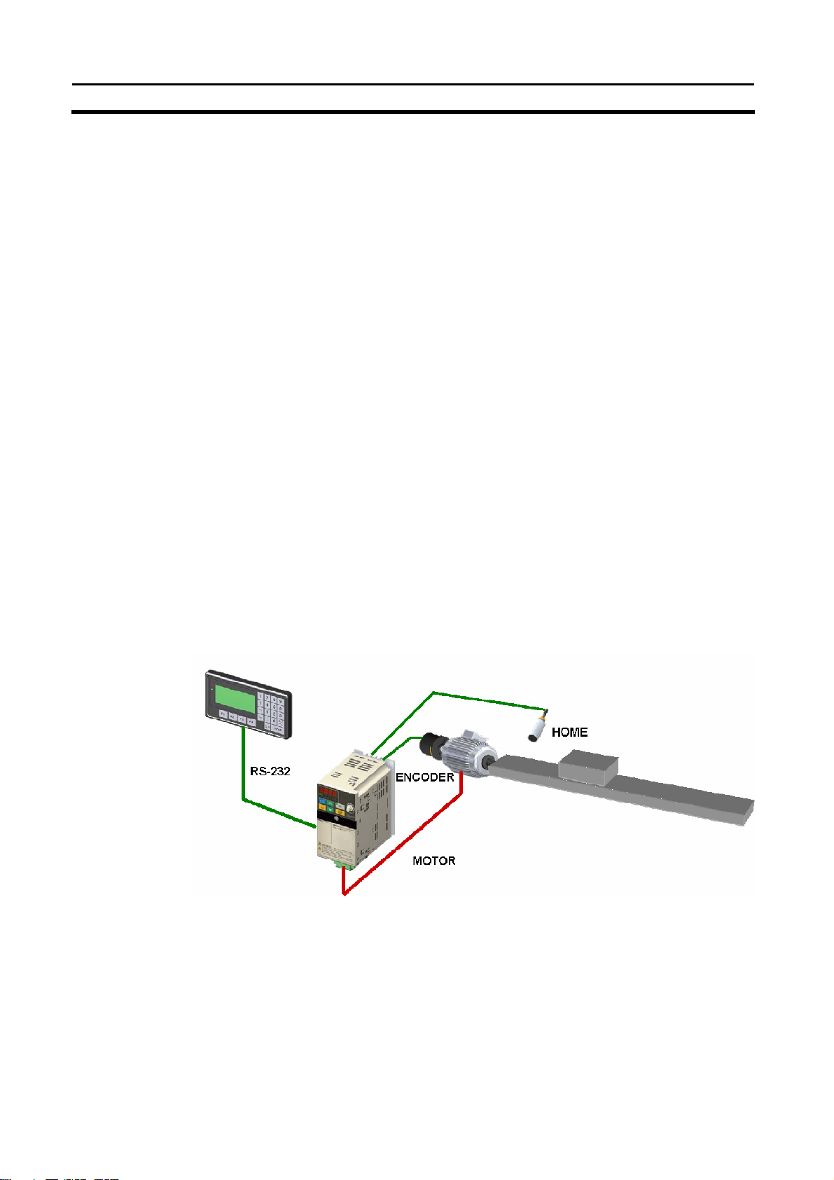
Example System Configuration
A basic standalone application with HMI:
SECTION 1
2
Page 16
I
ntroduction
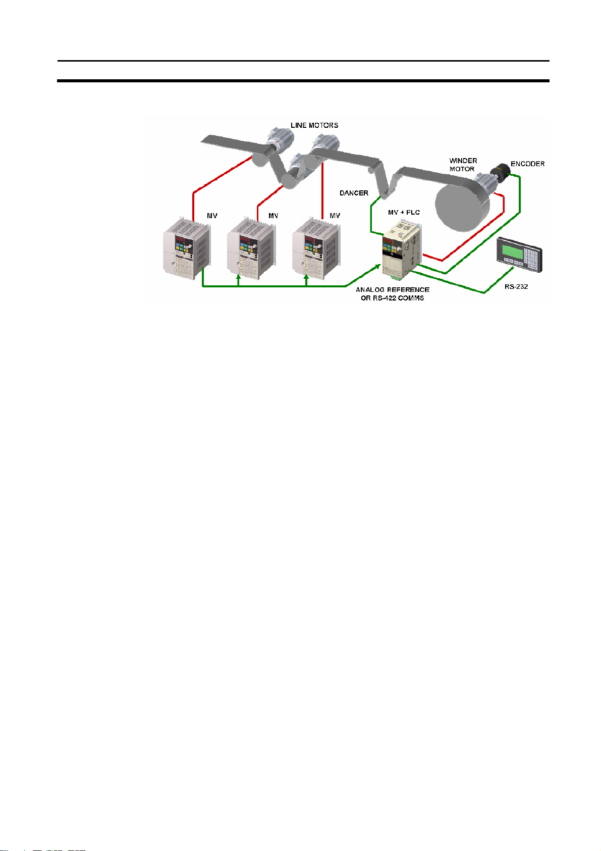
A typical winder application:
The 3G3MV and PLC Option Unit take care of diameter calculation, dancer
PID, user input, etc. The other simply run in speed control. This type of application uses both RS-232C and RS-422 communication.
Loss of Inverter functionality
Whenever the 3G3MV-P10CDT is attached to a 3G3MV Inverter, the follow-
ing functionality of the Inverter is lost:
• Modbus communication through the RS-422 interface of the Inverter is
disabled. The Modbus communication through the RJ-45 connector is still
available.
Inverter-interface restriction
The following resources have limited control:
• Only one analog input can be read directly. The other input can be read
by using the Transfer command in combination with PID with feedback.
• The analog outputs cannot be controlled by the 3G3MV-P10CDT
Note Minimum Inverter firmware version requirement: 24
SECTION 1
3
Page 17

I
ntroduction
SECTION 1
1-1-2 Overview of 3G3MV-P10CDT Functions
Main function Variations/Details
Inverter interface Direct interface with 3G3MV Inverter through
• IR-memory
• DM-memory
• Transfer command
Interrupts
High-speed counters
Pulse outputs
Synchronized pulse
control
Quick-response input 2 inputs
Input time constant Determines the input time constant for all inputs. (Settings: 1, 2, 3, 5, 10, 20, 40, or 80 ms)
Calendar/Clock Shows the current year, month, day of the week, day of the month, hour, minute, and
Interrupt inputs
2 inputs
Response time: 50 µs
Interval timer interrupts
1 input
Set value: 0.5 to 319,968 ms
Precision: 0.1 ms
1 input, see note 1.
Differential phase mode (5 kHz)
Pulse plus direction input mode (20 kHz)
Up/down input mode (20 kHz)
Increment mode (20 kHz)
Interrupt inputs (counter mode)
2 inputs
Incrementing counter (2 kHz)
Decrementing counter (2 kHz)
• 2 outputs:
Single-phase pulse output without acceleration/deceleration (See note 2.)
10 Hz to 10 kHz
• 2 outputs:
Variable duty ratio pulse output (See note 2.)
0.1 to 999.9 Hz, duty ratio 0 to 100%
• 1 output:
Pulse output with trapezoidal acceleration/deceleration (See note 2.)
Pulse plus direction output, up/down pulse output, 10 Hz to 10 kHz
1 point, see notes 1 and 2.
Input frequency range: 10 to 500 Hz, 20 Hz to 1 kHz, or 300 Hz to 20 kHz
Output frequency range: 10 Hz to 10 kHz
Minimum input signal width: 50 µs
second.
Scheduled interrupts
One-shot interrupt
No interrupt High-speed counter
Count-check interrupt
(An interrupt can be generated when the
count equals the set value or the count
lies within a preset range.)
No interrupt
Count-up interrupt
Note 1. This input is shared by the high-speed counter and synchronized pulse con-
trol functions.
2. This output is shared by the pulse output and synchronized pulse control
functions.
4
Page 18

I
ntroduction
SECTION 1
1-2 System Configurations
1-2-1 Unit types
3G3MV-P10CDT Units
Item 3G3MV-P10CDT-E 3G3MV-P10CDT3-E
PLC core CPM2C-S CPM2C-S
Inputs 6 24 VDC inputs 6 24 VDC inputs
3 sinking transistor outputs 3 sinking transistor outputs Outputs
1 relay output 1 relay output
Peripheral port Yes Yes
RS-232C port Yes Yes
RS-422/485 port No Yes
Calendar/Clock No Yes
Memory backup Flash memory and capacitor Flash memory and battery
5
Page 19
I
ntroduction
1-3 3G3MV-P10CDT Structure and Operation
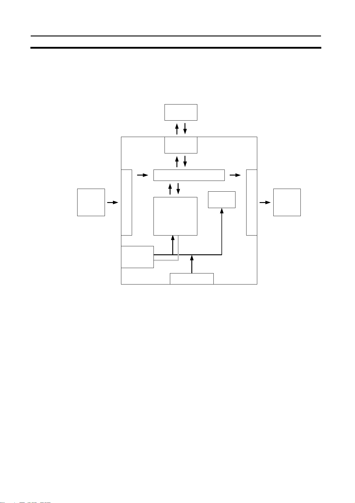
1-3-1 3G3MV-P10CDT Structure
The following diagram shows the internal structure of the Unit.
3G3MV
Inverter
Inverter
interface
I/O memory
SECTION 1
External
input
devices
Input circuits
Communications
ports
Settings
Program
Settings
Communications
Switches
PC Setup
Settings
Output circuits
External
output
devices
I/O Memory The program reads and writes data in this memory area during execution.
Part of the I/O memory contains the bits that reflect the status of the PLC’s
inputs and outputs. Parts of the I/O memory are cleared when the power is
turned ON and other parts are retained.
Program This is the program written by the user. The 3G3MV-P10CDT executes the
program cyclically. (Refer to section 1-3-4 Cyclic Operation and Interrupts for
details.) The program can be divided broadly into two parts: the “main program” that is executed cyclically and the “interrupt programs” that are executed only when the corresponding interrupt is generated.
PLC Setup The PLC Setup contains various startup and operating parameters. The PLC
Setup parameters can be changed from a Programming Device only; they
cannot be changed from the program.
Some parameters are accessed only when PLC’s power supply is turned ON
and others are accessed regularly while the power is ON. It will be necessary
to turn the power OFF and then ON again to enable a new setting if the parameter is accessed only when the power is turned ON.
Note Refer to 4-1 PLC-setup for details on the PLC Setup.
Communications The Communications Switches determine whether the peripheral port and
Switches RS-232C port connected through the communications port operate with the
standard communications settings or the communications settings in the PLC
Setup.
Inverter Interface The PLC core communicates to the Inverter through IR-, DM-memory, either
by direct mapping or through the Transfer command.
Note Refer to section 5-4 Transfer command for more details.
6
Page 20

I
ntroduction
SECTION 1
1-3-2 Operating Modes
3G3MV-P10CDT Units have 3 operating modes: PROGRAM, MONITOR,
and RUN.
PROGRAM Mode The program cannot be executed in PROGRAM mode. This mode is used to
perform the following operations in preparation for program execution.
•
Changing initial/operating parameters such as those in the PLC Setup
•
Writing, transferring, or checking the program
•
Checking wiring by force-setting and force-resetting I/O bits
Caution The PLC continues to refresh I/O bits even if the PLC is in PROGRAM mode,
MONITOR Mode The program is executed in MONITOR mode and the following operations
so devices connected to output points may operate unexpectedly if the
corresponding output bit is turned ON by transferring I/O memory or forcesetting output bits from a Programming Device.
can be performed from a Programming Device. In general, MONITOR mode
is used to debug the program, test operation, and make adjustments.
•
Online editing
•
Monitoring I/O memory during operation
•
Force-setting/force-resetting I/O bits, changing set values, and changing
present values during operation
RUN Mode The program is executed at normal speed in RUN mode. Operations such as
online editing, force-setting/force-resetting I/O bits, and changing set values/
present values cannot be performed in RUN mode, but the status of I/O bits
can be monitored.
7
Page 21

I
ntroduction
1-3-3 Operating Mode at Startup
The operating mode of the 3G3MV-P10CDT when the power is turned ON
depends upon the setting of pin 2 on the DIP switch on the front of the
3G3MV-P10CDT, the PLC Setup settings in DM 6600, and the Programming
Console’s mode switch setting if a Programming Console is connected.
PLC Setup setting
Word Bits Setting
DM 6600
Note 1. The operating mode at startup depends upon the setting of DIP switch pin 2
and the Programming Device connected to the communications port (peripheral port).
Programming Device Pin 2 OFF Pin 2 ON
None PROGRAM mode RUN mode
Programming Console Operating mode set on the Programming Console’s
Other device PROGRAM mode
The default setting for bits 08 to 15 of DM 6600 is 00. If this default setting is
used and pin 2 is OFF, the 3G3MV-P10CDT will automatically start operating
in RUN mode when the power is turned ON.
Note 2. If pin 2 is OFF and only an RS-232C cable is connected to the communica-
tions port (i.e., there is no peripheral port connection), the 3G3MV-P10CDT
will automatically start operating in RUN mode when the power is turned ON.
Example Cable Connections:
CS1W-CN118 and XW2Z-200S/500S
CS1W-CN118 and XW2Z-200S-V/500S-V
CPM2C-CN111 and XW2Z-200S/500S (no peripheral port connection)
CPM2C-CN111 and XW2Z-200S-V/500S-V (no peripheral port connection)
08 to 15
00 to 07
SECTION 1
Operating mode
00 (Hex) See note 1.
01 (Hex) Startup mode is the same as the operating
mode before power was interrupted.
02 (Hex) Startup mode is determined by bits 00 to 07.
00 (Hex) PROGRAM mode
01 (Hex) MONITOR mode
02 (Hex) RUN mode
mode switch
8
Page 22

I
ntroduction
SECTION 1
1-3-4 Cyclic Operation and Interrupts
Basic CPU Operation Initialisation processing is performed when the power is turned on. If there
are no initialisation errors, the overseeing processes, program execution, I/O
refreshing, and communications port servicing are performed repeatedly (
clically).
Initial Processing
cy-
Inverter interface
initial Processing
Common
processing
Inverter IN
refresh
Program
execution
processing
Cycle time
calculation
processing
I/O refesh
Inverter OUT
refresh
Inverter Modbus
transfer
RS-232C port
service
Inverter Interface initial processing
Inverter Interface status refresh
Inverter Interface control data refresh
Inverter Interface Modbus command execution
When Inverter processing is ended by END refresh timing, a maximum of
eight data items are read or writen. If the Inverter is currently processing,
nothing will be done and it will be checked with the next scan.
Peripheral port
service
The cycle time can be read from a Programming Device.
AR 14 contains the maximum cycle time and AR15 contains the present
cycle time in multiples of 0.1 ms.
9
Page 23

I
ntroduction
1-4 Comparison with the CPM2C-S
Item CPM2C-S 3G3MV-P10CDT
Basic instructions 14 14 Instruction set
Special instructions 105 instructions, 185 variations 105 instructions, 185 variations
Instruction
execution times
Program capacity 4,096 words 4,096 words
number of I/O
points
and Expansion
I/O Units
I/O memory
Basic instructions
Special instructions
Stand-alone CPU Unit 10 points 10 points Maximum
CPU Unit with Expansion I/O
Units
Maximum number of Units A maximum of 3 Units. --- Expansion Units
Available models Expansion I/O Units, Analog I/O
Input bits IR 00000 to IR 00915 IR 00000 to IR 00005 I/O memory
Output bits IR 01000 to IR 01915 IR 01000 to IR 01003
Work bits 672 bits:
SR (Special Relay) area 448 bits:
TR (Temporary Relay) area 8 bits: TR0 to TR7 8 bits: TR0 to TR7
HR (Holding Relay) area 320 bits:
AR (Auxiliary Relay) area 384 bits:
LR (Link Relay) area 256 bits:
Timer/Counter area 256 bits:
DM (Data
Memory) area
Inverter Interface --- 288 bits:
Read/write
area
Reserved --- 14 words:
Read-only
area
PLC Setup 56 words:
LD: 0.64 µs LD: 0.64 µs
MOV(21): 7.8 µs MOV(21): 7.8 µs
362 points max. ---
---
Unit, Temperature Sensor Unit,
and CompoBus/S I/O Link Unit
880 bits:
IR 02800 to IR 02915,
IR 03800 to IR 04915,
IR 20000 to IR 22715
SR 22800 to SR 25515
HR 0000 to HR 1915
AR 0000 to AR 2315
LR 0000 to LR 1515
TIM/CNT 000 to TIM/CNT 255
2,022 words:
DM 0000 to DM 2021
456 words:
DM 6144 to DM 6599
DM 6600 to DM 6655
IR 00100 to IR 00915,
IR 01100 to IR 02815,
IR 03000 to IR 04915,
IR 22000 to IR 22715
448 bits:
SR 22800 to SR 25515
320 bits:
HR 0000 to HR 1915
384 bits:
AR 0000 to AR 2315
256 bits:
LR 0000 to LR 1515
256 bits:
TIM/CNT 000 to TIM/CNT 255
1,993 words:
DM 0000 to DM 1985
DM 2041 to DM 2047
DM 1986 to DM 1999
456 words:
DM 6144 to DM 6599
56 words:
DM 6600 to DM 6655
IR 20000 to IR 21715
19 words:
DM 2022 to DM 2040
SECTION 1
10
Page 24

I
ntroduction
Item CPM2C-S 3G3MV-P10CDT
Memory backup
CompoBus/S Master Functions Up to 32 Slaves can be
DeviceNet Slave Functions DeviceNet Remote I/O Link
Interrupt inputs (interrupt input mode) 2 2
Interrupt inputs
(counter mode)
Quick-response
inputs
High-speed
counter
Program area, read-only DM
area (including PLC Setup)
Read/write DM area, HR
area, AR area, and counters
Counter mode Incrementing counter
Counter upper limit 2 kHz 2 kHz
SR 244 to SR 247 Contains counter PV. Contains counter PV.
Method(s) to read counter
PV
Method to change counter
PV
One-shot mode Yes Yes Interval timer
Scheduled interrupt mode Yes Yes
Setting the quick-response
function
INT(89) (Mask) Not supported (ignored) Not supported (ignored)
INT(89) (Read mask) Reads mask status. Reads mask status.
INT(89) (Clear) Not supported (ignored) Not supported (ignored)
Minimum pulse width
Count mode Differential-phase (up/down)
Max. counter frequency 5 kHz in differential-phase
Counter PV range –8,388,608 to 8,388,607 in
Flash memory backup Flash memory backup
Internal battery backup (2-year
life-time at 25°C, replaceable)
connected and up to 256 I/O
points can be controlled.
Use up to 1,024 I/O points in
the I/O Link. Explicit Message
Communications Any PLC data
area can be accessed from the
Master.
Decrementing counter
Read SR 244 to SR247.
Execute PRV(62).
Execute INI(61). Execute INI(61).
PLC Setup PLC Setup
50 µs min. 50 µs min.
mode
Pulse plus direction mode
Up/down pulse mode
Increment mode
(up/down) mode
20 kHz in pulse plus direction
mode, up/down pulse mode,
and increment mode
differential-phase (up/down)
mode,
pulse plus direction mode, and
up/down pulse mode
0 to 16,777,215 in increment
mode
SECTION 1
Unit with clock:
Internal battery backup (5-year
lifetime at 25°C, nonreplaceable)
Unit without clock: Capacitor
backup (10-day backup at
25°C)
---
---
Incrementing counter
Decrementing counter
Read SR 244 to SR247.
Execute PRV(62).
Differential-phase (up/down)
mode
Pulse plus direction mode
Up/down pulse mode
Increment mode
5 kHz in differential-phase
(up/down) mode
20 kHz in pulse plus direction
mode, up/down pulse mode,
and increment mode
–8,388,608 to 8,388,607 in
differential-phase (up/down)
mode,
pulse plus direction mode, and
up/down pulse mode
0 to 16,777,215 in increment
mode
11
Page 25

I
ntroduction
Item CPM2C-S 3G3MV-P10CDT
Check when registering target value match table
Same direction, same SV not
possible
SECTION 1
Same direction, same SV not
possible
12
Page 26

I
ntroduction
SECTION 1
Item CPM2C-S 3G3MV-P10CDT
High-speed
counter
(continued)
Pulse synchronization Supported. Supported.
Pulse output
control
Communications switch This switch determines whether
Battery
Method used to reference
the target value match
interrupt table
Reading range-comparison
results
Reading status Check AR 1108 (comparison in
Trapezoidal acceleration/
deceleration
PWM(––) output Supported. Supported.
Number of simultaneous
pulse outputs
Maximum frequency 10 kHz max. 10 kHz max.
Minimum frequency 10 Hz 10 Hz
Pulse output quantity –16,777,215 to 16,777,215 –16,777,215 to 16,777,215
Direction control Supported. Supported.
Positioning to absolute
positions
Bit status while pulses are
being output
Reading PV Read SR 228 through SR231 or
Resetting PV Supported. Supported.
Status outputs Accelerating/decelerating
Words containing
time info.
Battery Internal lithium battery backup Unit with clock:
Battery replacement Possible Not possible
Comparison of all values in the
table, regardless of order of
appearance in table
Check AR 1100 to AR1107 or
execute PRV(62).
progress), check AR1109
(high-speed counter PV
overflow/underflow), or execute
PRV(62).
Supported with ACC(––). The
initial frequency can be set.
2 max. 2 max.
Supported. Supported.
No effect No effect
execute PRV(62).
PV overflow/underflow
Pulse quantity set
Pulse output completed
Pulse output status
Internal Internal or none Clock function
AR 17 to AR 21 AR 17 to AR 21
communications are governed
by the standard settings or PLC
Setup settings. Also sets the
Programming Device
connection.
Comparison of all values in the
table, regardless of order of
appearance in table
Check AR 1100 to AR1107 or
execute PRV(62).
Check AR 1108 (comparison in
progress), check AR1109
(high-speed counter PV
overflow/underflow), or execute
PRV(62).
Supported with ACC(––). The
initial frequency can be set.
Read SR 228 through SR231 or
execute PRV(62).
Accelerating/decelerating
PV overflow/underflow
Pulse quantity set
Pulse output completed
Pulse output status
This switch determines whether
communications are governed
by the standard settings or PLC
Setup settings. Also sets the
Programming Device
connection.
Internal lithium battery backup
Life expectancy/
backup time
Battery error detection Supported. Supported.
2-year lifetime at 25°C Unit with clock: 5-year lifetime
at
25°C
13
Page 27

I
ntroduction
Item CPM2C-S 3G3MV-P10CDT
Communications
(in CPU Unit)
Input time constant Can be set to 1, 2, 3, 5, 10, 20,
Peripheral port (via
communications
port)
RS-232C port (via
communications
port)
RS-422 port Through CIF-unit Peripheral bus
Programming Console (Set with
Communications Switch.)
Peripheral bus (Set with
Communications Switch.)
Host Link (with Slave-initiated
communications)
No-protocol
Peripheral bus (Set with
Communications Switch.)
Host Link
No-protocol
1:1 PLC LInk
1:1 NT Link
40, or 80 ms. (Default: 10 ms)
SECTION 1
Programming Console (Set with
Communications Switch.)
Peripheral bus (Set with
Communications Switch.)
Host Link (with Slave-initiated
communications)
No-protocol
Peripheral bus (Set with
Communications Switch.)
Host Link
No-protocol
1:1 PLC LInk
1:1 NT Link
Host Link (with Slave-initiated
communications)
No-protocol
Can be set to 1, 2, 3, 5, 10, 20,
40, or 80 ms. (Default: 10 ms)
14
Page 28

I
ntroduction
Differences in I/O Memory
IR Area Differences
Function CPM2C-S 3G3MV-P10CDT
CompoBus/S input bits IR 020 to IR 027
CompoBus/S output bits IR 030 to IR 037
Work bits 672 bits:
Inverter Interface 288 bits:
AR Area Differences
Function CPM2C-S 3G3MV-P10CDT
DeviceNet Status AR 00
CompoBus/S Active Slave Flags
and Communications Error Flags
CompoBus/S Master ASIC Error AR 1315
DM Area Differences
Function CPM2C-S 3G3MV-P10CDT
Inverter Interface 19 words:
Reserved
PLC Setup Differences
Function CPM2C-S 3G3MV-P10CDT
Maximum number of
CompoBus/S nodes
CompoBus/S communications
mode
DeviceNet Read/Write area
(Default or DM 6606 to DM 6609)
DeviceNet I/O Link Write Area
data area
DeviceNet I/O Link Write Area
number of bytes
DeviceNet I/O Link Write Area
starting address
DeviceNet I/O Link Read Area
data area
DeviceNet I/O Link Read Area
number of bytes
DeviceNet I/O Link Read Area
starting address
IR 028 to IR 029
IR 038 to IR 049
IR 200 to IR 227
AR 04 to AR 07
DM 6603 bits 00 to 03
DM 6603 bits 04 to 07
DM 6605 bits 00 to 03
DM 6606 bits 00 to 07
DM 6606 bits 08 to 15
DM 6607 bits 00 to 15
DM 6608 bits 00 to 07
DM 6608 bits 08 to 15
DM 6609 bits 00 to 15
SECTION 1
880 bits:
IR 00100 to IR 00915
IR 01100 to IR 02815
IR 03000 to IR 04915
IR 22000 to IR 22715
IR 20000 to IR 21715
DM 2022 to DM 2040
14 words:
DM 1986 to DM 1999
15
Page 29

I
ntroduction
1-5 Preparation for Operation
Follow the steps listed below when setting up a 3G3MV-P10CDT system.
1, 2, 3... 1. System Design
•
Select a 3G3MV-P10CDT Unit with the specifications required in the
controlled system.
Design external fail-safe circuits such as interlock circuits and limit cir-
•
cuits.
2.
3.
4.
5.
6.
7.
Installation
•
Install the Unit on the Inverter
Wiring
•
Wire the Inverter and I/O devices.
Connect communications devices if necessary.
•
Connect the Programming Console.
•
Initial Settings
•
Set the Communications Switches on the front of the CPU Unit, if nec-
essary. (The switches must be set when a device other than the Programming Console is connected or the standard communications settings are not used.)
• Connect the Programming Console, set the mode switch to PROGRAM
mode, and turn ON the Inverter.
Check the Unit’s LED indicators and the Programming Console’s dis-
•
play.
Clear the PLC’s memory. (All Clear)
•
Make PLC Setup settings.
•
Create Ladder Program
•
Create a ladder program to control the system.
Write Ladder Program in PLC
•
Write the ladder program in the PLC with the Programming Console or
transfer the program to the PLC from the Support Software.
Test Run
•
Check I/O wiring in PROGRAM mode.
• Check and debug program execution in MONITOR mode.
SECTION 1
16
Page 30

SECTION 2 Unit Components and Specifications
This section provides the technical specifications of the 3G3MV-P10CDT Units and describes the main components of
these Units.
2-1 Specifications .......................................................................................................................................................18
2-1-1 General Specifications ..................................................................................................................................18
2-1-2 Characteristics ..............................................................................................................................................18
2-1-3 I/O Specifications ..........................................................................................................................................21
2-1-3-1 Input Specifications................................................................................................................................................... 21
2-1-3-2 Output Specifications ................................................................................................................................................ 23
2-1-4 Dimensions....................................................................................................................................................25
2-2 Unit Components..................................................................................................................................................26
2-2-1 CPU Unit Component Names .......................................................................................................................26
2-2-2 CPU Unit Component Descriptions..............................................................................................................26
17
Page 31

Unit Components and Specifications
2-1 Specifications
2-1-1 General Specifications
Item Specifications
Rated power supply voltage 24 VDC
Vibration resistance 0.15 mm (10-57 Hz)
9.8 m/s2 (57-150 Hz)
In all directions (X, Y, Z)
Ambient operating temperature -10 to 45 °C
Ambient operating relative
humidity
Ambient storage temperature -20 to 70 °C
Atmosphere Must be free from corrosive gas
Power Consumption 2W (Supplied internally)
Note The above figure for power consumption includes the power consumption of
10% to 90% (no condensation)
the Programming Console.
2-1-2 Characteristics
+10%
/
(External power supply for I/O)
–15%
SECTION 2
Item Specifications
Control method Store program method
I/O control method Cyclic scan method
Programming language Ladder chart method
Instruction length 1 step/1 instruction; 1 to 5 words/1 instruction
Basic 14 types (Same as for Programmable Slaves.) Instruction
types
speed
Program capacity 4,096 words
Maximum number of I/O points 10
Input bits 00000 to 00015 (6 physical inputs)
Output bits 01000 to 01003 (4 physical outputs)
Area allocated to Inverter 320 bits: 20000 to 21915
IR Area 880 bits: IR 00100 to IR 00915 (words IR 001 to IR 009),
SR Area 448 bits: SR 22800 to SR 25507 (words SR 228 to SR 255)
TR Area 8 bits (TR 0 to TR 7)
HR Area 320 bits: HR 0000 to HR 1915 (words HR 00 to 19)
AR Area 384 bits: AR 0000 AR 2315 (words AR 00 to AR 23)
LR Area 256 bits: LR 0000 to LR 1515 (words LR 00 to LR 15)
Timer/Counter Area 256 bits: TC 000 to TC 255
DM Area
Special 105 types, 185 instructions (Same as for Programmable Slaves.)
Basic instructions 0.64 µs (LD) Processing
Special instructions 7.8 µs (MOV)
IR 01100 to IR 02815 (words IR 011 to IR 028),
IR 03000 to IR 04915 (words IR 030 to IR 049),
IR 22000 to IR 22715 (words IR 220 to IR 227)
Read/Write 2029 words (DM 0000 to DM 0999, DM 1019 to DM 2047)
DM 2000 to DM 2021: Error Log Storage Area
Read only 456 words (DM6144 to 6599)
18
Page 32

Unit Components and Specifications
SECTION 2
Item Specifications
Allocated to
19 words (DM 2022 to DM 2040)
Inverter
PLC Setup 56 words (DM 6599 to DM 6655)
Item Specifications
Interrupt
processing
External
interrupts
Scheduled
2 bits (Used in common for input interrupt counter mode and highspeed inputs.)
1 bit (Scheduled interrupts or one-shot interrupts)
interrupts
Pulse outputs 2 bits (without acceleration/deceleration; 10 Hz to 10 kHz each; without
directional control).
Or 1 bit (with trapezoidal acceleration/deceleration; 10 Hz to 10 kHz
each; with directional control).
Or 2 bits (Variable duty ratio output).
Pulse synchronous control 1 bit
A high-speed counter can be combined with pulse output, and the
input pulse frequency from the high-speed counter can be multiplied by
a fixed factor for pulse output.
Pulse catch inputs 2 bits
Minimum pulse input: 50 µs max.
Used in common by input interrupts and input interrupt counter mode.
Analog volume None
Input time constant
(ON response time =
Only all inputs can be set.
(1 ms / 2 ms / 3 ms / 5 ms / 10 ms / 20 ms / 40 ms / 80 ms)
OFF response time)
Clock function Yes
Communication function Port 1 = Peripheral and RS-422
Host Link, Peripheral bus, No-protocol, Programming
Console
Port 2 = RS-232C port:
Host Link, no-protocol, 1:1 PLC Link, 1:1 NT Link
Power-interruption hold function Holds the contents of HR, AR, CNT, and DM Areas.
Non-volatile memory, User program, DM (Read only), PLC Setup Memory backup
Fixed internal lithium battery (5 years, not replaceable by the user) or
capacitor
DM (Read/Write), HR, SR and CNT Areas
Self-diagnostic function CPU errors, memory errors, communications errors, setting errors,
battery errors
Program check No END instruction, program errors (regularly checked during
operation)
Connected
tools
CX-Programmer After Version 2.1
Programming
C200H-PRO27, CQM1-PRO01
Console
SSS PC98 & PC/AT (SYSMAC Support Software, All version)
Sysdrive
After version 2
Configurator
19
Page 33

Unit Components and Specifications
Note 1. The DM area, HR area, AR area, and counter values are backed up. If the
backup battery or capacitor is discharged, the contents of these areas will be
lost and the data values will revert to the defaults.
2.
When data has been changed in any of these areas, write the new values to
3.
The contents of the program area, read-only DM area (DM6144 to DM6599),
and PLC Setup (DM 6600 to DM 6655) are stored in flash memory. The contents of these areas will be read from flash memory the next time the power
is turned ON, even if the backup battery or capacitor is discharged.
flash memory by switching the 3G3MV-P10CDT to MONITOR or RUN mode,
or by turning the power OFF and then ON again.
Changes made while in MONITOR mode using, for example, online editing,
are written to flash memory in real-time.
SECTION 2
20
Page 34

Unit Components and Specifications
2-1-3 I/O Specifications
2-1-3-1 Input Specifications
Item Inputs Specification
Input voltage All 24 VDC
Input impedance
Input current
IN00000 to IN00001
IN00002 to IN00004
IN00005
2.7 kΩ
3.9 kΩ
4.7 kΩ
IN00000 to IN00001 8 mA typical
IN00002 to IN00004 6 mA typical
IN00005 5 mA typical
IN00000 to IN00001 17 VDC min., 5 mA ON voltage/current
IN00002 to IN00005 14.4 VDC min., 3.5 mA
OFF voltage/current All 5.0 VDC max., 1.1 mA
ON delay All 1 to 80 ms max. Default: 10 ms (See note.)
OFF delay All 1 to 80 ms max. Default: 10 ms (See note.)
Circuit configuration
IN00000 to IN00001
+10%
/
–15%
SECTION 2
IN00002 to IN00004
IN00005
Note The input time constant can be set to 1, 2, 3, 5, 10, 20, 40, or 80 ms in the
PLC Setup.
21
Page 35

Unit Components and Specifications
SECTION 2
High-speed Counter Inputs
The following Unit input bits can be used as high-speed counter inputs. The
maximum count frequency is 5 kHz in differential phase mode and 20 kHz in
the other modes.
Function Input
Differential phase
mode
IN00000 A-phase pulse input Pulse input Increment pulse input Increment pulse input
IN00001 B-phase pulse input Direction input Decrement pulse input Normal input
IN00002 Z-phase pulse input or hardware reset input
(IN00002 can be used as a normal input when it is not used as a high-speed counter input.)
Pulse plus direction
input mode
Up/down input mode Increment mode
The minimum pulse widths for inputs IN00000 (A-phase input) and IN00001
(B-phase input) are as follows:
The minimum pulse width for input IN00002 (Z-phase input) is as follows:
Interrupt Inputs
The 3G3MV-P10CDT is equipped with inputs that can be used as interrupt
inputs (interrupt input mode or counter mode) and quick-response inputs.
The minimum pulse width for these inputs is 50 µs.
Inputs IN00003 and IN00004 can be used as interrupt inputs.
22
Page 36

Unit Components and Specifications
2-1-3-2 Output Specifications
Relay Output
Item Specification
Maximum switching capacity 2 A, 250 VAC (cos =1)
2A, 24VDC
Minimum switching load 10 mA, 5 VDC
Service life of relay
ON delay 15 ms max.
OFF delay 15 ms max
Circuit configuration
Electrical: 150,000 operations (24 VDC resistive load)
100,000 operations (240 VAC inductive load cos =0.4)
Mechanical: 20,000,000 operations
SECTION 2
Note The service life of relay output contacts shown in the table assumes the
worst conditions. The following graph shows the results of Omron’s service
life tests at a switching rate of 1,800 times/hour.
23
Page 37

Unit Components and Specifications
Transistor Outputs (Sinking)
Item Specification
Maximum switching capacity 4.5 to 30VDC, 0.2 A/output
Minimum switching capacity 0.5 mA
Maximum inrush current 0.9 A for 10 ms
Leakage current 0.1 mA
Residual voltage 1.5 V max.
ON response time 20 µs max.
OFF response time 40 µs max. for 4.5 to 26.4 VDC, 10 to 100 mA
0.1 ms max for 4.5 to 30 VDC, 10 to 200 mA
Fuse One fuse per output (cannot be replaced by user)
Circuit configuration
SECTION 2
Note 1. When using OUT01000 or OUT01001 as a pulse output, connect a dummy
resistor as required to bring the load current between 0.01 and 0.1 A. If the
load current is below 0.1 A, the ON-to-OFF response time will be longer and
high-speed pulses (source-type transistor outputs) will not be output. If the
load current is above 0.1 A, the transistor will generate more heat and components may be damaged.
Caution Do not apply voltage in excess of the maximum switching capacity to an
output terminal. It may result in damage to the product or fire.
24
Page 38

Unit Components and Specifications
2-1-4 Dimensions
SECTION 2
128
68
55
25
Page 39

Unit Components and Specifications
2-2 Unit Components
2-2-1 CPU Unit Component Names
Front view Bottom-view
4. PC status indicators
5. Communications port
6. Communications switch
1. DIP switch
2. Input indicators
3. Output indicators
8. RS-422/485 switch
9. Terminating
Resistance switch
10. I/O connector
Rear-view
13. Low battery
detection switch
OFF
SECTION 2
7. RS-422/485 port
11. Relay connector
12. FE-connection
2-2-2 CPU Unit Component Descriptions
1,2,3.. 1. DIP switch
• RS-232C and Peripheral Port Settings
12
ON
ON
Pin 1 Effective Port Settings
OFF
(default)
The ports operate according to the settings in the PLC Setup.
RS-232C port settings: DM 6645 to DM 6649
Peripheral port settings: DM 6650 to DM 6654
ON The ports operate with the standard communications settings.
• Operating Mode at Startup
Pin 2 determines the operating mode at startup only if there isn’t a Programming Device connected to the peripheral port.
Programming Device
Startup mode with
connected
None PROGRAM mode RUN mode
Programming Console Operating mode set on the Programming
Console’s mode switch
Other device PROGRAM mode
pin 2 OFF (default)
Startup mode with
pin 2 ON
26
Page 40

Unit Components and Specifications
2. Input indicators (yellow)
The input indicators are lit when the corresponding input terminal is ON. The
status of an input indicator will reflect the status of the input even when that
input is being used for a high-speed counter.
Note a) When interrupt inputs are used in interrupt input mode, the indicator
b) Input indicators will reflect the status of the corresponding inputs
3. Output indicators (yellow)
The output indicators are lit when the corresponding output terminal is ON.
The indicators are lit during I/O refreshing. The status of an output indicator
will also reflect the status of the corresponding output when the output is being used as a pulse output.
4. PLC status indicators
The following indicators show the operating status of the PLC.
Indicator Status Meaning
(green)
RUN
(green)
ERR/ALM
(red)
COMM1
(yellow)
(yellow)
SECTION 2
may not light even when the interrupt condition is met if the input is
not ON long enough.
even when the PLC is stopped, but the corresponding input bits will
not be refreshed.
ON Power is being supplied to the unit PWR
OFF Power isn’t being supplied to the unit
ON The PLC is operating in RUN or MONITOR
mode
OFF The PLC is in PROGRAM mode or a fatal
error has occurred.
ON A fatal error has occurred. (PLC operation
stops.)
Flashing A non-fatal error has occurred. (PLC
operation continues.)
OFF Indicates normal operation.
Flashing Data is being transferred via the peripheral or
RS-422/485 port.
OFF Data isn’t being transferred via communica-
tions port.
Flashing Data is being transferred via the RS-232C portCOMM2
OFF Data isn’t being transferred via communica-
tions port.
5. Communications port
Connects the PLC to a Programming Device (including Programming Con-
soles), host computer, or standard external device. Use a proper Connecting
Cable (CPM2C-CN111, CS1W-CN114, CS1W-CN118, or CS1W-CN226).
Note a) A CQM1H-PRO01-E Programming Console can be connected di-
rectly to the PLC.
b) A C200H-PRO27-E Programming Console can be connected di-
rectly to the PLC with a CS1W-CN224/CN624 Connecting Cable.
c) Use a CPM2C-CN111 or CS1W-CN114 Connecting Cable to con-
nect to the communications port as a peripheral port. The communications port can be used simultaneously as both a peripheral port
and RS-232C port by using the CPM2C-CN111 Connecting Cable.
d) Use a CPM2C-CN111, CS1W-CN118 or CS1W-CN226 Connecting
Cable to connect to the communications port as a RS-232C port.
27
Page 41

Unit Components and Specifications
Note The peripheral port and RS-422/485 port cannot be used simultaneously.
When using the peripheral port disconnect any devices connected to the RS422/485 port.
6. Communications switch
Switch to select port 1 type of connected device
OFF (default) Programming Console
ON RS-422/485 communication
7. RS-422/485 port (3G3MV-P10CDT3-E only)
Used to connect to host computers, or standard external devices.
Terminal Arrangement
SECTION 2
The communications port can be used simultaneously as both a peripheral port and RS-232C port by using the CPM2C-CN111 Connecting Cable
Position Communication port 1
Receive data
(input)
Send data
(output)
RDA- RDB+ Shield SDA- SDB+
Connector: Phoenix MSTB 2.5/5-STF-5.08AU
Note The maximum line length is 500 m.
Note The peripheral port and RS-422/485 port cannot be used simultaneously.
When using the peripheral port disconnect any devices connected to the RS422/485 port.
8. RS-422/485 switch (3G3MV-P10CDT3-E only)
Switch to select 4-wire (RS-422) or 2-wire (RS-485) communication
Position Status
OFF (down) (default) 4-wire communications
ON (up) 2-wire communications
9. Terminating Resistance switch (3G3MV-P10CDT3-E only)
Position Termination
OFF (down) (default) Disabled
ON (up) Enabled
Set this switch to ON only for double-ended connection to a Host Link net-
work.
10. I/O connector
28
Connects the CPU Unit to external input and output devices.
Sinking outputs
IN0 (A)
IN1 (B)
IN2 (Z)
IN3
IN4
IN5
COM
COM
OUT0
OUT1
OUT2
COM (-)
1 2 3 4 5 6 7 8 9 10 11 12
Connector: WAGO 733-112 (wire cross section 0.08 to 0.50 mm
OUT3
COM
1 2
2
)
Page 42

Unit Components and Specifications
11. Relay connector
SECTION 2
Enabled
Disabled
OFF
Connects the CPU Unit to an external output devices.
Connector: WAGO 734-102 (wire cross section 0.08 to 1.50 mm
2
)
12. FE-connection
AMP tab to connect functional earth. Internally connected to pin 3 of the RS-
422/485 connector and to the shell of the peripheral connector.
13. Low battery detection switch (3G3MV-P10CDT3-E only)
This switch enables or disables the detection of a low-battery error.
Position Low-battery detection
ON (up) (default) Error detection enabled
OFF (down) Error detection disabled
29
Page 43

Page 44

SECTION 3 Installation and Wiring
This section provides information on installing and wiring a 3G3MV-P10CDT Unit. Be sure to follow the directions and
precautions in this section when installing the 3G3MV-P10CDT in a panel or cabinet and wiring I/O.
Installation ............................................................................................................................................................32
3-1
3-2 Wiring...................................................................................................................................................................35
3-3 Connecting I/O Devices .......................................................................................................................................35
3-4 Wiring Communication Cables ............................................................................................................................37
3-5 Programming Device Connections.......................................................................................................................37
31
Page 45

I
nstallation and Wiring
3-1 Installation
SECTION 3
WARNING
WARNING
WARNING
WARNING
WARNING
WARNING
Caution Do not store, install, or operate the product in the following places. Doing so
Caution Do not allow foreign objects to enter inside the product. Doing so may result in
Caution Do not apply any strong impact. Doing so may result in damage to the product
Caution Be sure to wire correctly and securely. Not doing so may result in injury or
Caution Be sure to firmly tighten the screws on the terminal block. Not doing so may
Caution Carefully handle the product because it uses semiconductor elements.
Caution Take appropriate and sufficient countermeasures when installing systems in
Do not touch the conductive parts such as internal PCBs or terminal blocks
while power is being supplied. Doing so may result in electrical shock.
Turn ON the input power supply only after mounting the front cover, terminal
covers, bottom cover, Operator, and optional items. Leave them mounted in
place while power is being supplied. Not doing so may result in electrical
shock, malfunction, or damage to the product.
Wiring, maintenance, or inspection must be performed by authorized
personnel. Not doing so may result in electrical shock or fire.
Wiring, maintenance, or inspection must be performed after turning OFF the
power supply, confirming that the CHARGE indicator (or status indicators) is
OFF, and after waiting for the time specified on the Inverter front cover. Not
doing so may result in electrical shock.
Do not damage, pull on, apply stress to, place heavy objects on, or pinch the
cables. Doing so may result in electrical shock, operation stoppage, or
burning.
Do not attempt to disassemble or repair the Unit. Doing either of these may
result in electrical shock, injury, or damage to the product.
may result in electrical shock, fire or damage to the product.
Locations subject to direct sunlight.
•
Locations subject to temperatures or humidity outside the range specified
•
in the specifications.
Locations subject to condensation as the result of severe changes in
•
temperature.
Locations subject to corrosive or flammable gases.
•
Locations subject to exposure to combustibles.
•
Locations subject to dust (especially iron dust) or salts.
•
Locations subject to exposure to water, oil, or chemicals.
•
Locations subject to shock or vibration.
•
fire or malfunction.
or malfunction.
damage to the product.
result in fire, injury, or damage to the product.
Careless handling may result in malfunction.
the following locations. Not doing so may result in equipment damage.
Locations subject to static electricity or other forms of noise.
•
Locations subject to strong electromagnetic fields and magnetic fields.
•
Locations subject to possible exposure to radioactivity.
•
Locations close to power supplies.
•
32
Page 46

I
nstallation and Wiring
Mounting Procedure
Caution Before installing and wiring an Optional Unit, always turn OFF the power to
1. Turn OFF the main circuit power supply for the Inverter, wait for at least one
SECTION 3
the SYS-DRIVE 3G3MV Inverter and wait for the CHARGE indicator to turn
OFF.
minute from the time the LED indicator or the CHARGE indicator goes out,
and remove the front cover of the Inverter along with the Operator.
2. Wire the main circuit terminals and control circuit terminals of the Inverter.
(When the 3G3MV-P10CDT Unit is mounted, the terminal block of the Inverter will be covered. Therefore, be sure to complete wiring for the Inverter
terminals first.)
3. When the Operator of the Inverter is removed, it will be possible to see a
block secured at three places underneath. Using pliers or another appropriate tool, loosen the fixings, and remove the block. The connector for Optional
Unit connections will become visible. At this point, ensure that dirt or foreign
objects do not enter the connector.
33
Page 47

I
nstallation and Wiring
SECTION 3
4. Mount the mounting base (included as an accessory) onto the screw-hole
originally used for holding the Operator and the terminal cover to the body of
the Inverter, and using one of the provided screws, secure the mounting
base.
5. After aligning the positions of the PLC Unit connector and the Inverter connector, push the frames of the Inverter and the Unit together until they click.
6. Tighten the fixing screws on the upper part of the PLC Unit, to the mounting
base attached in step 4.
7. Attach the Operator and the LED hood to the front side of the PLC Unit. Remove the screw of the Inverter front cover and use it to secure the LED hood
and the operator to the Inverter.
34
Page 48

I
nstallation and Wiring
3-2 Wiring
SECTION 3
WARNING
Only basic insulation is provided for the control circuit terminals. Additional
insulation may be necessary in the end product.
These circuits are not separated from hazardous circuits by protective
separation, but only with basic insulation. These circuits cannot be accessed
and must not be interconnected with any circuits which are accessible, unless
they are isolated from accessible circuits by supplemental insulation. These
circuits can be connected only to the following circuits:
30 VDC or less (overvoltage category 2)
250 VAC or less (overvoltage category 2)
3-3 Connecting I/O Devices
Wire inputs and outputs to the 3G3MV-P10CDT Unit as shown in the f
ing diagrams.
WARNING
Note When equipment must conform to the EC Directives (Low-voltage Direc-
Caution Check that wiring has been performed correctly before supplying power.
I/O Configuration The following diagrams show the I/O configurations.
The PLC outputs may remain ON or OFF due to deposits on or burning of the
output relay or destruction of the output transistors. External safety measures
must be provided to ensure safety in the system. Not providing proper safety
measures may result in serious accidents.
tives), use a power supply with double insulation or reinforced insulation.
Supplying power with incorrect wiring may result in damage to internal circuits.
Sinking Transistor Outputs
ollow-
35
Page 49

I
nstallation and Wiring
SECTION 3
I/O Connector
24VDC
24VDC
Load
Load
Load
00000
00001
00002
00003
00004
00005
COM
COM
01000
01001
01002
COM(-)
1
2
3
4
5
6
7
8
9
10
11
12
36
Page 50

I
nstallation and Wiring
Do not exceed the output capacity or the maximum common current for tran-
sistor outputs shown in the following table.
Item Specification
Output Capacity 200 mA at 24 VDC
Cage Clamp Both the relay and I/O-connector make use of cage-clamp technology. The
picture below shows how the wires should be inserted.
SECTION 3
Tools to be used for the I/O connector:
• Perpendicular to the wire (top-half of the picture above)
Philips screw-driver 2.5 x 0.4 mm
• In-line with the wire (bottom-half of the picture above)
WAGO tool 233-332
Tools to be used for the relay connector:
• Perpendicular to the wire (top-half of the picture above)
Philips screw-driver 2.5 x 0.4 mm
• In-line with the wire (bottom-half of the picture above)
Philips screw-driver 2.5 x 0.4 mm
3-4 Wiring Communication Cables
When wiring the RS-422/485 communication cable, make sure to use
shielded cable with twisted wires. The shield of the cable can be connected
to the middle pin of the RS-422/485 connector. Internally this pin is connected to the Functional Earth tab.
The Functional earth tab is also connected to the shielding of the Peripheral
connector.
3-5 Programming Device Connections
For a complete overview of Programming Device connections see section
3-4-9 of W377 Operation Manual CPM2C-S.
Note When using CX-Programmer, select CPM2*-S* as PLC Device Type.
37
Page 51

SECTION 4 Communication, Counter and Pulse
This section describes the communication settings and the use of the counter and pulse output functionality of the
3G3MV-P10CDT.
PLC-setup Communication.................................................................................................................................. 39
4-1
4-1-1 RS-232C Port Communications Settings...................................................................................................... 39
4-1-2 Peripheral RS-422/485 Port Communications Settings ............................................................................... 40
4-2 High-speed Counters ........................................................................................................................................... 42
4-3 Input Interrupts In Counter Mode........................................................................................................................ 45
4-4 Pulse Output Functions........................................................................................................................................ 48
4-4-1 Using Single-phase Pulse Fixed Duty Ratio ................................................................................................ 49
4-4-2 Using Pulse Outputs With Variable Duty Ratio ........................................................................................... 52
4-4-3 Using Pulse Outputs With Trapezoidal Acceleration/Deceleration ............................................................. 53
38
Page 52

Communication, Counter and Pulse
4-1 PLC-setup Communication
4-1-1 RS-232C Port Communications Settings
The following settings are effective after transfer to the PLC.
If pin 2 of the 3G3MV-P10CDT Unit’s DIP switch is ON, communications
through the 3G3MV-P10CDT’s RS-232C port are governed by the default
settings (all 0) regardless of the settings in DM 6645 through DM 6649.
Word(s) Bit(s) Function
DM 6645
DM 6646
DM 6647 00 to 15 Transmission delay (0000 to 9999 BCD sets a delay of 0 to 99,990 ms.)
DM 6648
00 to 03 Port settings
0: Standard (1 start bit, 7 data bits, even parity, 2 stop bits, 9,600 bps), Host Link unit
number: 0
1: Settings in DM 6646
(Any other setting will cause a non-fatal error and AR 1302 will turn ON.)
04 to 07 CTS control setting
0: Disable CTS control; 1: Enable CTS control
(Any other setting will cause a non-fatal error and AR 1302 will turn ON.)
08 to 11 Link words for 1:1 data link
0: LR 00 to LR 15 (Any other settings are ineffective.)
12 to 15 Communications mode
0: Host Link; 1: No-protocol; 2: 1:1 PLC Link Slave; 3: 1:1 PLC Link Master; 4: NT Link
(Any other setting causes a non-fatal error and turns ON AR 1302.)
00 to 07 Baud rate
00: 1,200 bps; 01: 2,400 bps; 02: 4,800 bps; 03: 9,600 bps; 04: 19,200 bps
08 to 15 Frame format
Start bits Data bits Stop bits Parity
00: 1 bit 7 bits 1 bit Even
01: 1 bit 7 bits 1 bit Odd
02: 1 bit 7 bits 1 bit None
03: 1 bit 7 bits 2 bits Even
04: 1 bit 7 bits 2 bits Odd
05: 1 bit 7 bits 2 bits None
06: 1 bit 8 bits 1 bit Even
07: 1 bit 8 bits 1 bit Odd
08: 1 bit 8 bits 1 bit None
09: 1 bit 8 bits 2 bits Even
10: 1 bit 8 bits 2 bits Odd
11: 1 bit 8 bits 2 bits None
(Any other setting specifies standard settings (1 start bit, 7 data bits; even parity, 2 stop
bits, 9,600 bps), causes a non-fatal error, and turns ON AR 1302.)
(Any other setting specifies a delay of 0 ms, causes a non-fatal error, and turns ON
AR 1302.)
00 to 07 Node number (Host Link)
00 to 31 (BCD)
(Any other setting specifies a node number of 00, causes a non-fatal error, and turns
ON AR 1302.)
08 to 11 Start code selection for no-protocol communications
0: Disables start code; 1: Enables start code in DM 6649
(Any other setting disables the start code, causes a non-fatal error, and turns ON AR 1302.)
SECTION 4
39
Page 53

Communication, Counter and Pulse
12 to 15 End code selection for no-protocol communications
0: Disables end code; 1: Enables end code in DM 6649; 2: Sets end code of CR, LF.
(Any other setting disables the end code, causes a non-fatal error, and turns ON AR 1302.)
Word(s) Bit(s) Function
DM 6649
00 to 07 Start code (00 to FF)
(This setting is valid only when bits 8 to 11 of DM 6648 are set to 1.)
08 to 15 When bits 12 to 15 of DM 6648 set to 0:
Sets the number of bytes to receive. (00: 256 bytes; 01 to FF: 1 to 255 bytes)
When bits 12 to 15 of DM 6648 set to 1:
Sets the end code. (00 to FF)
4-1-2 Peripheral RS-422/485 Port Communications Settings
The following settings are effective after transfer to the PLC.
If the 3G3MV-P10CDT Unit’s Communications Switch is ON, communica-
tions through the peripheral port are governed by the default settings (all 0)
regardless of the settings in DM 6650 through DM 6654.
The 3G3MV-P10CDT’s Communications Switch setting has no effect on
communications with a Programming Console connected to the peripheral
port or Support Software set for peripheral bus communications. The
3G3MV-P10CDT Unit will auto-detect either Programming Device and automatically establish communications.
Word(s) Bit(s) Function
DM 6650
DM 6651
00 to 03 Port settings
0: Standard (1 start bit, 7 data bits, even parity, 2 stop bits, 9,600 bps), Host Link unit
number: 0
1: Settings in DM 6651
(Any other setting will cause a non-fatal error and AR 1302 will turn ON.)
04 to 11 Not used.
12 to 15 Communications mode
0: Host Link or peripheral bus; 1: No-protocol
(Any other setting causes a non-fatal error and turns ON AR 1302.)
00 to 07 Baud rate
00: 1,200 bps; 01: 2,400 bps; 02: 4,800 bps; 03: 9,600 bps; 04: 19,200 bps
08 to 15 Frame format
Start bits Data bits Stop bits Parity
00: 1 bit 7 bits 1 bit Even
01: 1 bit 7 bits 1 bit Odd
02: 1 bit 7 bits 1 bit None
03: 1 bit 7 bits 2 bits Even
04: 1 bit 7 bits 2 bits Odd
05: 1 bit 7 bits 2 bits None
06: 1 bit 8 bits 1 bit Even
07: 1 bit 8 bits 1 bit Odd
08: 1 bit 8 bits 1 bit None
09: 1 bit 8 bits 2 bits Even
10: 1 bit 8 bits 2 bits Odd
11: 1 bit 8 bits 2 bits None
(Any other setting specifies standard settings (1 start bit, 7 data bits; even parity, 2 stop
bits, 9,600 bps), causes a non-fatal error, and turns ON AR 1302.)
SECTION 4
40
Page 54

Communication, Counter and Pulse
DM 6652 00 to 15 Transmission delay (0000 to 9999 BCD sets a delay of 0 to 99,990 ms.)
(Any other setting specifies a delay of 0 ms, causes a non-fatal error, and turns ON
AR 1302.)
Word(s) Bit(s) Function
DM 6653
DM 6654
00 to 07 Node number (Host Link)
00 to 31 (BCD)
(Any other setting specifies a node number of 00, causes a non-fatal error, and turns
ON AR 1302.)
08 to 11 Start code selection for no-protocol communications
0: Disables start code; 1: Enables start code in DM 6654
(Any other setting disables the start code, causes a non-fatal error, and turns ON AR 1302.)
12 to 15 End code selection for no-protocol communications
0: Disables end code; 1: Enables end code in DM 6649; 2: Sets end code of CR, LF.
(Any other setting disables the end code, causes a non-fatal error, and turns ON AR 1302.)
00 to 07 Start code (00 to FF)
(This setting is valid only when bits 8 to 11 of DM 6653 are set to 1.)
08 to 15 When bits 12 to 15 of DM 6653 set to 0:
Sets the number of bytes to receive. (00: 256 bytes; 01 to FF: 1 to 255 bytes)
When bits 12 to 15 of DM 6653 set to 1:
Sets the end code. (00 to FF)
SECTION 4
41
Page 55

Communication, Counter and Pulse
4-2 High-speed Counters
3G3MV-P10CDT Units have four points for high-speed counters: One point
for a high-speed counter with a maximum response frequency of 20 kHz, and
three points for interrupt inputs (counter mode).
For more details please refer to Programming Manual W353
High-speed counters
High-speed counter No interrupts
1 point
Interrupt inputs
(counter mode)
2 points
SECTION 4
Target value com-
parison interrupts
Count check
interrupts
Range comparison
interrupts
No interrupts
Count-up
interrupts
42
Page 56

Communication, Counter and Pulse
SECTION 4
PLC Setup Set the PLC Setup areas related to the high-speed counter as follows:
High-speed counter usage
Input mode
Reset method
(Use/not use 00002 as ordinary input)
Word Bits Function Setting
DM 6642
00 to 03 High-speed counter input mode setting
0: Differential phase input 5 kHz
1: Pulse + direction input 20 kHz
2: Up/down input 20 kHz
4: Increment 20 kHz
04 to 07 High-speed counter reset method setting
0: Phase-Z signal + software reset
1: Software reset
08 to 15 High-speed counter usage setting
00: Do not use.
01: Use as high-speed counter
02: Use as pulse synchronization control
(10 Hz to 500 Hz)
03: Use as pulse synchronization control
(20 Hz to 1 kHz)
04: Use as pulse synchronization control
(300 Hz to 20 kHz)
DM 6642, bits 08 to 15
DM 6642, bits 00 to 03
DM 6642, bits 04 to 07
0, 1, 2, or 4
0 or 1
01
The new settings for the System Setup go into effect when operation begins
(when PROGRAM mode is changed to MONITOR or RUN mode), or when
the 3G3MV-P10CDT’s power is turned ON.
43
Page 57

Communication, Counter and Pulse
SECTION 4
Ladder Diagram The following table shows the instructions related to high-speed counter
Programming control.
Instruction Control Operation
(@)CTBL(63)
(@)INI(61)
(@)PRV(62)
(@)INT(89)
Register target value
comparison table
Register range
comparison table
Register target value
comparison table and
start comparison
Register range
comparison table and
start comparison
Start comparison Starts comparison with registered
Stop comparison
Change PV Changes the high-speed counter PV.
Read PV Reads the high-speed counter PV.
Read status
Read range comparison
result
Mask all interrupts Prohibits all interrupts, including
Unmask all interrupts
Registers target value comparison
table.
Registers range comparison table.
Registers target value comparison table
and starts comparison.
Registers range comparison table and
starts comparison.
comparison table.
Stops comparison.
Reads the high-speed counter status.
Reads range comparison result.
interrupt inputs, interval timer interrupts,
high-speed counters, etc.
Permits all interrupts, including interrupt
inputs, interval timer interrupts,
high-speed counters, etc.
The following table shows the data areas related to high-speed counter con-
trol.
Word Bits Name Contents
00 to 15 248
249
252 00 High-speed counter reset When this bit turns ON, a
AR11
00 to 15
00 to 07 High-speed counter range
08 ON: Comparison in progress
09 High-speed counter PV
High-speed counter PV Reads high-speed counter
PV.
software reset is triggered for
the high-speed counter.
ON: Condition satisfied
comparison results
High-speed counter
comparison
overflow/underflow
OFF: Condition not satisfied
OFF: Comparison stopped
ON: Overflow/underflow
OFF: Normal
44
Page 58

Communication, Counter and Pulse
4-3 Input Interrupts In Counter Mode
The four built-in interrupt inputs in the 3G3MV-P10CDT Unit can be used in
counter mode as inputs of up to 2 kHz. These inputs can be used as either
incrementing counters or decrementing counters, triggering an interrupt (i.e.,
executing an interrupt subroutine) when the count matches the set value.
For more details please refer to Programming Manual W353
Procedure for Using Interrupt Inputs in Counter Mode
Set the interrupt number.
Select either incrementing or
decrementing count.
SECTION 4
Wire the inputs.
PLC Setup (DM 6628)
Create a ladder diagram program.
Input numbers: 00003 or 00004
1. Use as interrupt input (interrupt input
mode or counter mode)
INI(61): Change counter PV
INT(89): Refresh SV*
(PRV(62): Read counter PV
SBN(92) and RET(93): For creating interrupt subroutines.*
*Used only for count-up interrupts.
45
Page 59

Communication, Counter and Pulse
SECTION 4
PLC Setup The following table shows the settings in the PLC Setup area related to
interrupt input usage.
Word Bits Function Setting
DM 6628
00 to 03 Interrupt setting for
input 00003
04 to 07 Interrupt setting for
input 00004
08 to 15 Not used. 0
0: Normal input
1: Interrupt input
(interrupt input
mode or counter
mode)
2: Quick-response
input
1
The setting will go into effect when the mode is changed (from PROGRAM to
MONITOR/RUN) or when the power supply is turned ON to the 3G3MVP10CDT.
46
Page 60

Communication, Counter and Pulse
SECTION 4
Ladder Diagram The following table shows the instruction operations related to interrupt input
Programming (counter mode) control.
Instruction Control Operation
(@)INT(89)
(@)INI(61) Change PV Changes the counter’s PV.
(@)PRV(62) Read PV Reads the counter’s PV.
Refresh incrementing
counter SV
Refresh decrementing
counter SV
Mask all interrupts Prohibits all interrupts, including interrupt
Unmask all interrupts Permits all interrupts, including interrupt
Refreshes the counter’s SV and starts the
incrementing count.
Refreshes the counter’s SV and starts the
decrementing count.
inputs, interval timer interrupts, highspeed counters, etc.
inputs, interval timer interrupts, highspeed counters, etc.
The functions related to input interrupts (counter mode) are executed accord-
ing to the data areas shown in the following table.
Word Bits Name Contents
240 00 to 15 SV area for input interrupt (counter mode) 0
241 00 to 15 SV area for input interrupt (counter mode) 1
242 00 to 15 SV area for input interrupt (counter mode) 2
243 00 to 15 SV area for input interrupt (counter mode) 3
244 00 to 15 PV area for input interrupt (counter mode) 0
245 00 to 15 PV area for input interrupt (counter mode) 1
246 00 to 15 PV area for input interrupt (counter mode) 2
247 00 to 15 PV area for input interrupt (counter mode) 3
Stores the
counter’s set
value(SV) .
Stores the
counter’s
present value
(PV).
Refresh Incrementing Counter SV / Refresh Decrementing Counter SV
These functions store the counter’s set values in data areas and refresh them
by means of INT(89). In this way, they start the count operation for interrupt
inputs (counter mode) and they permit interrupts.
Storing Set Values in Data Areas
The counter’s set values are stored in words 240, 241, 242, and 243.
SR 240 SV for interrupt input (count mode) 0: 0000 to FFFF
SR 241 SV for interrupt input (count mode) 1: 0000 to FFFF
SR 242 SV for interrupt input (count mode) 2: 0000 to FFFF
SR 243 SV for interrupt input (count mode) 3: 0000 to FFFF
47
Page 61

Communication, Counter and Pulse
SECTION 4
4-4 Pulse Output Functions
The 3G3MV-P10CDT has two pulse outputs. By means of a selection in the
PLC Setup, these outputs can be used as two single-phase outputs without
acceleration and deceleration, two variable duty ratio pulse outputs, or pulse
outputs with trapezoidal acceleration/deceleration (one pulse + direction output and one up/ down pulse output). The pulse output PV coordinate system
can also be specified in the PLC Setup as either relative or absolute.
There are two pulse output modes: Independent mode, in which outputs are
stopped at a preset amount of pulses, and continuous mode, in which outputs are stopped by an instruction.
For more details please refer to Programming Manual W353
Item Single-phase
pulse outputs
without
accel/decel
Execution instructions PULS(65) and
SPED(64)
Output
number
Output frequency range 10 Hz to 10 kHz 0.1 to 999.9 Hz 10 Hz to 10 kHz 10 Hz to 10 kHz
Pitch 10 Hz 0.1 Hz 10 Hz 10 Hz
Up/down frequency pitch --- --- 10 Hz (See note 2.) 10 Hz (See note 2.)
Start speed pitch --- --- 10 Hz 10 Hz
Output mode Continuous,
Number of pulses 1 to 16777215 ---
Duty ratio (See note 3.) 50% 0 to 100% 50% 50%
Control
method
01000 Pulse output 0
(See note 1.)
01001 Pulse output 1
(See note 1.)
Independent
Movement
specification
Accel/decel
specification
Start speed
specification
Duty
specification
Yes No Yes Yes
No No Yes Yes
No No Yes Yes
No Yes No No
Variable duty
ratio pulse
outputs
PWM(––) PULS(65) and ACC(––)
Pulse output 0
(See note 1.)
Pulse output 1
(See note 1.)
Continuous Continuous, Independent Continuous,
Note 1. With single-phase pulse outputs, pulse outputs 0 and 1 can each be output
independently.
2. Pulse outputs can be accelerated or decelerated in units of 10 Hz every 10
ms.
3.
Actual pulses are affected by the transistor output’s ON response time (20 µs
max.) and OFF response time (40 µs max.).
Single-phase pulse outputs with trapezoidal
acceleration/deceleration
Pulse + direction
outputs
Pulse
output 0
±1 to 16777215 ±1 to 16777215
Pulse output CW
Direction
output
Up/down pulse
outputs
Pulse
output 0
Independent
pulse
output
CCW
pulse
output
48
Page 62

Communication, Counter and Pulse
4-4-1 Using Single-phase Pulse Fixed Duty Ratio
SECTION 4
Select the pulse output number.
Wire the outputs.
PLC Setup (DM 6629)
Create a ladder diagram program.
Single-phase Pulse Outputs
Pulse output number 0 or 1
Output numbers: 01000 and 010001
PV coordinatesystem for pulse output 0 and 1
PULS(65): For setting the number of pulses.
SPED(64): For pulse output control without acceleration and deceleration.
INI(61): For stopping pulse outputs and changing the pulse output PV.
PRV(62): For reading the pulse output PV and status.
PLC Setup Make the following settings in the PLC Setup.
Word Bits Function Setting
DM 6629
00 to 03 Pulse 0 PV
coordinate
system
04 to 07 Pulse 1 PV
coordinate
system
0: Relative coordinate
system
1: Absolute coordinate
system
Either 0 or
1
49
Page 63

Communication, Counter and Pulse
SECTION 4
DM 6642 08 to 15 High-speed
counter
setting
00: Do not use.
01: Use as high-speed
counter
02: Use as synchronized
pulse control (10 to 500 Hz).
03: Use as synchronized
pulse control (20 Hz to 1
kHz).
04: Use as synchronized
pulse control (300 Hz to 20
kHz).
Either 00
or 01
If absolute pulses are specified with PULS(65), be sure to set the absolute
coordinate system (1).
Synchronized pulse control cannot be used simultaneously.
The settings will go into effect when the mode is changed (from PROGRAM
to MONITOR/RUN) or when the power supply is turned ON to the PLC.
Ladder Diagram The following table shows the instruction operations related to pulse outputs
Programming without acceleration and deceleration (fixed duty ratio).
Instruction Control Operation
(@)PULS(65) Set number of pulses Sets the number of pulses to be
output
in independent mode.
(@)SPED(64)
Set frequency and start
pulse outputs
Change frequency Changes the frequency for outputs in
Stop pulse outputs Stops the pulse outputs (by changing
Stop pulse outputs Stops the pulse outputs. (@)INI(61)
Change pulse output PV Changes the pulse output PV.
Read pulse output PV Reads the pulse output PV. (@)PRV(62)
Read pulse output status Reads the pulse output status.
Sets the frequency for outputs in the
independent mode or continuous
mode,
and starts the pulse outputs.
the independent mode or continuous
mode.
the speed to a frequency of 0 Hz).
50
Page 64

Communication, Counter and Pulse
SECTION 4
The following table shows the words and bits related to pulse outputs without
acceleration and deceleration (fixed duty ratio).
Word Bits Name Contents
228 00 to 15 Pulse output PV 0, rightmost 4 digits
229 00 to 15 Pulse output PV 0, leftmost 4 digits
230 00 to 15 Pulse output PV 1, rightmost 4 digits
231 00 to 15 Pulse output PV 1, leftmost 4 digits
04 Pulse output 0 PV reset Clears PV 0 when ON. 252
05 Pulse output 1 PV reset Clears PV 1 when ON.
AR 11
AR 12
12 Pulse output 0 PV over-
flow/underflow
13 Number of pulses set for pulse
output 0
14 Pulse output completed for pulse
output 0
15 Pulse output in progress for pulse
output 0
12 Pulse output 1 PV over-
flow/underflow
13 Number of pulses set for pulse
output 1
14 Pulse output completed for pulse
output 1
15 Pulse output in progress for pulse
output 0
Cannot be used as
work bits even when
not used as pulse
outputs.
ON: Occurred
OFF: Normal
ON: Set (by PULS(65))
OFF: Not set
ON: Completed (by
SPED(64))
OFF: Not completed
ON: In progress (by
SPED(64))
OFF: Stopped
ON: Occurred
OFF: Normal
ON: Set (by PULS(65))
OFF: Not set
ON: Completed (by
SPED(64)) OFF: Not
completed
ON: In progress (by
SPED(64)) OFF:
Stopped
51
Page 65

Communication, Counter and Pulse
4-4-2 Using Pulse Outputs With Variable Duty Ratio
SECTION 4
Select the pulse output number.
Wire the outputs.
Create a ladder diagram program.
Pulse Outputs With Variable Duty Ratio
Pulse output number 0 or 1
Output numbers: 01000 and 010001
PWM(---): For setting the frequency and duty ratio.
INI(61): For stopping outputs.
PRV(62): For reading the pulse output status.
PLC Setup Make the following settings in the PLC Setup.
Word Bits Function Setting
DM 6642 08 to 15 High-speed
counter
setting
00: Do not use.
01: Use as high-speed counter
02: Use as synchronized pulse
control (10 to 500 Hz).
03: Use as synchronized pulse
control (20 Hz to 1 kHz).
04: Use as synchronized pulse
control (300 Hz to 20 kHz).
Either
00 or
01
Synchronized pulse control cannot be used simultaneously.
The settings will go into effect when the mode is changed (from PROGRAM
to MONITOR/RUN) or when the power supply is turned ON to the PLC.
52
Page 66

Communication, Counter and Pulse
SECTION 4
Ladder Diagram The following table shows the instruction operations related to pulse outputs
Programming with variable duty ratio.
Instruction Control Operation
(@)PWM(––)
(@)INI(61) Stop pulse outputs Stops the pulse outputs.
(@)PRV(62) Read pulse output status Reads the pulse output status (during
Pulse output with
variable duty ratio
Change duty ratio Changes the duty ratio during pulse
Sets the frequency and duty ratio and
starts the pulse outputs.
while pulse outputs with variable duty
ratio are already in progress.
pulse outputs).
The following table shows the words and bits related to pulse outputs with
variable duty ratio.
Word Bit Name Contents
AR 11 15 Pulse output in progress
for pulse output 0
AR 12 15 Pulse output in progress
for pulse output 1
ON: In progress (by SPED(64),
ACC(––), or PWM(––))
OFF: Stopped
ON: In progress (by SPED(64),
ACC(––), or PWM(––))
OFF: Stopped
4-4-3 Using Pulse Outputs With Trapezoidal Acceleration/Deceleration
Select the direction and control method.
Select the pulse output number.
Wire the outputs.
PLC Setup (DM6629)
Create a ladder diagram program.
Pulse + direction or up/down output
Pulse output number 0
Output numbers: 01000 and 01001
PV coordinate system for pulse output number 0
PULS(65): For setting the number of output pulses.
ACC(---): For controlling pulse outputs with trapezoidal acceleration
and deceleration
INI(61): For stopping pulse outputs and changing the pulse output PV.
PRV(62): For reading the pulse output PV and status.
53
Page 67

Communication, Counter and Pulse
Pulse Outputs With Trapezoidal Acceleration and Deceleration
SECTION 4
PLC Setup Make the following settings in the PLC Setup.
Word Bits Function Setting
DM 6629 00 to 03 Pulse 0 PV
coordinate
system
DM 6642 08 to 15 High-speed
counter
setting
0: Relative coordinate
system
1: Absolute coordinate
system
00: Do not use.
01: Use as high-speed
counter
02: Use as synchronized
pulse control (10 to 500 Hz).
03: Use as synchronized
pulse control (20 Hz to 1
kHz).
04: Use as synchronized
pulse control (300 Hz to 20
kHz).
If absolute pulses are specified with PULS(65), be sure to set the absolute
coordinate system (1).
Synchronized pulse control cannot be used simultaneously.
The settings will go into effect when the mode is changed (from PROGRAM
to MONITOR/RUN) or when the power supply is turned ON to the PLC.
Either 0 or
1
Either 00
or 01
54
Page 68

Communication, Counter and Pulse
SECTION 4
Ladder Diagram The following table shows the instruction operations related to pulse outputs
Programming with trapezoidal acceleration and deceleration (fixed duty ratio).
Instruction Control Operation
(@)PULS(65) Set number of pulses Sets the number of pulses to be
output in independent mode.
(@)ACC(––)
Set frequency and start
pulse outputs
Change frequency Changes the frequency during pulse
Stop pulse outputs Decelerates pulse outputs to a stop
Stop (decelerate stop)
pulse outputs
Change pulse output PV Changes the pulse output PV.
Read pulse output PV Reads the pulse output PV. (@)PRV(62)
Read pulse output status Reads the pulse output status.
Sets the target frequency, starting
frequency, and acceleration/deceleration rate for outputs in
independent mode or continuous
mode, and starts the pulse outputs.
output in continuous mode by
accelerating or decelerating according
to the specified acceleration/deceleration rate.
according to the specified
acceleration/deceleration rate.
Stops the pulse outputs. (@)INI(61)
The following table shows the words and bits related to pulse outputs with
trapezoidal acceleration and deceleration (fixed duty ratio).
Word Bits Name Contents
228 00 to 15 Pulse output PV 0, rightmost 4 digits
229 00 to 15 Pulse output PV 0, leftmost 4 digits
230 00 to 15 Pulse output PV 1, rightmost 4 digits
231 00 to 15 Pulse output PV 1, leftmost 4 digits
04 Pulse output 0 PV reset Clears PV 0 when ON. 252
05 Pulse output 1 PV reset Clears PV 1 when ON.
AR 11
11 Pulse output status for pulse output 0 ON: Accelerating or
12 Pulse output 0 PV over-
flow/underflow
13 Number of pulses set for pulse
output 0
14 Pulse output completed for pulse
output 0
15 Pulse output in progress for pulse
output 0
Cannot be used as
work bits even when
not used as pulse
outputs.
decelerating
OFF: Constant speed
ON: Occurred
OFF: Normal
ON: Set
OFF: Not set
ON: Completed
OFF: Not completed
ON: In progress (by
SPED(64), ACC(––), or
PWM(––))
OFF: Stopped
55
Page 69

SECTION 5 Inverter Interface
This section describes the interface to the Inverter.
5-1
Inverter interface.................................................................................................................................................. 57
5-2 I/O Allocation IR ................................................................................................................................................. 57
5-3 I/O Allocation DM............................................................................................................................................... 60
5-3-1 Controlling Inverter I/O ............................................................................................................................... 61
5-4 Transfer command............................................................................................................................................... 61
5-4-1 Parameter Reading ...................................................................................................................................... 62
5-4-2 Parameter Writing........................................................................................................................................ 63
5-4-3 Transfer Timing Chart ................................................................................................................................. 64
5-4-4 Transfer Timing Chart in case of Errors...................................................................................................... 65
5-4-5 Transfer Timing Chart for Cancelling Processing....................................................................................... 66
5-4-6 Transfer Ladder Program ............................................................................................................................ 66
56
Page 70

I
nverter Interface
SECTION 5
5-1 Inverter interface
The communication between the PLC and the Inverter is performed by:
• Inverter functionality mapped in IR (section 5-2)
• Inverter functionality mapped in DM (section 5-3)
• Through the Transfer command (section 5-4)
5-2 I/O Allocation IR
The contents of the IR area is refreshed and updated with each scan.
Word(s) Bit(s) Function Inverter
Register
200
201
202
00 RUN (ON: During RUN) 002C.0
01 Zero speed (ON: Zero speed) 002C.1
02 Reverse operation (ON: Reverse operation) 0001.1
03 Error-reset signal (IR 20709) (ON: Error-reset signal active) ---
04 Frequency agree (ON: Frequency agree) 002C.2
05 Inverter ready (ON: Inverter ready) 002C.6
06 Warning (nonfatal error) (ON: Warning occurring) 002C.3
07 Fault (ON: Fault occurring) 002C.14
08 OPE error (ON: OPE error occurring) ---
09 Momentary power interruption recovery (ON: Power restored) ---
10 RUN command mode (ON: Controlled by Inverter interface;
OFF: Other)
11 Terminal MA output status (ON: Closed) 002D.0
12 Terminal P1 output status (ON: Closed) 002D.1
13 Terminal P2 output status (ON: Closed) 002D.2
14 to 15 Reserved ---
00 Reserved ---
01 Main circuit voltage low (UV1) 0021.12
02 Control power supply error (UV2) 0021.13
03 Reserved ---
04 Load short-circuit (SC) (Note 1.) 0029.0
05 Ground fault (GF) (Note 1.) 0029.1
06 Overcurrent (OC) 0021.0
07 Overvoltage (OV) 0021.1
08 Inverter overheat (OH) 0021.3
09 Reserved ---
10 Motor overload (OL1) 0021.9
11 Inverter overload (OL2) 0021.2
12 Overtorque detection (OL3) 0021.10
13 to 15 Reserved ---
00 External fault 3 (EF3) ---
01 External fault 4 (EF4) ---
02 External fault 5 (EF5) ---
03 External fault 6 (EF6) ---
04 External fault 7 (EF7) ---
05 to 09 Reserved ---
10 Input phase-failure (PF) (Note 1.) 0029.2
11 Output phase-failure (LF) (Note 1.) 0029.3
002C.10
Read/
write
Readonly
Readonly
Readonly
57
Page 71

I
nverter Interface
SECTION 5
Word(s) Bit(s) Function Inverter
203
204
205
206
207
208
209 00 /NetRef 1 (ON: Inverter reference enabled; OFF: PLC enabled) (Note
12 Reserved ---
13 Operator connection error (OPR) 0021.15
14 to 15 Reserved ---
Register
00 to 05 Reserved ---
06 External fault (EF0) 0021.7
07 Loss of PID feedback (FBL) 0021.6
08 Low torque detection (UL3) ---
09 to 14 Reserved ---
15 Hardware error (Fxx) 0021.8
00 Terminal S1 (ON: Closed) 002B.0
01 Terminal S2 (ON: Closed) 002B.1
02 Terminal S3 (ON: Closed) 002B.2
03 Terminal S4 (ON: Closed) 002B.3
04 Terminal S5 (ON: Closed) 002B.4
05 Terminal S6 (ON: Closed) 002B.5
06 Terminal S7 (ON: Closed) 002B.6
07 to 15 Reserved ---
00 NetRef status (OFF: Inverter reference enabled; ON: PLC enabled)
(Note 2.)
01 NetCtrl status(OFF: Inverter control enabled; ON: PLC enabled)
(Note 3.)
02 to 07 Reserved ---
08 Stall prevention operating flag ---
09 to 15 Reserved ---
00 Inverter Ready (error detected by mutual diagnosis) (ON: Normal;
OFF: Error)
01 Transfer Completion (ON: Transfer completed) ---
02 Transfer Error (ON: Error; OFF: Normal) ---
03 Transfer Busy (ON: Busy; OFF: Ready for transfer) ---
04 to 15 Reserved ---
00 Forward/Stop (ON: Forward operation) ---
01 Reverse/Stop (ON: Reverse operation) ---
02 Multi-function input 3 (Set by n052.) 0001.6
03 Multi-function input 4 (Set by n053.) 0001.7
04 Multi-function input 5 (Set by n054.) 0001.8
05 Multi-function input 6 (Set by n055.) 0001.9
06 Multi-function input 7 (Set by n056.) 001.10
07 Reserved ---
08 External fault (ON: Fault EFO) 0001.2
09 Fault reset (ON: Reset command) 0001.3
10 to 13 Reserved ---
14 Error log clear ---
15 External Baseblock command (BB) (Note 1.) 002A.3
00 Multi-function contact output (ON: Output ON) 0009.0
01 Multi-function output 1 (ON: Output ON) 0009.1
02 Multi-function output 2 (ON: Output ON) 0009.2
03 to 15 Reserved ---
4.)
---
---
---
--- Read/
Read/
write
Readonly
Readonly
Readonly
Readonly
Read/
write
Read/
write
write
58
Page 72

I
nverter Interface
SECTION 5
01 /NetCtrl 1 (ON: Inverter control enabled; OFF: PLC enabled) (Note 5.) ---
02 to 15 Reserved ---
Word(s) Bit(s) Function Inverter
Register
210
211 to
217
00 Transfer Command (Read) (ON: Start processing) ---
01 Transfer Command (Write) (ON: Start processing) ---
02 to 15 Reserved ---
00 to 15 Reserved. Can be used as work bits. --- Read/
Note 1. These functions are provided for 5.5kW and 7.5kW Inverters only.
Note 2. NetRef is the inverse of /NetRef (209.00)
Note 3. NetCtrl is the inverse of /NetCtrl (209.01)
Note 4. When /NetRef is turned OFF, the PLC is defining the Frequency Reference
When /NetRef is turned ON, the Inverter is defining the Frequency Reference
After power on the this bit is turned OFF (PLC reference)
Note 5. When /NetCtrl is turned OFF, the PLC is controlling the Inverter
When /NetCtrl is turned ON, other sources are controlling the Inverter
After power on the this bit is turned OFF (PLC controlling)
Caution At power up, the following Inverter status flags toggle before they reflect the
actual status of the Inverter:
• IR 200.05 Inverter Ready
• IR 200.06 Inverter Warning
Wait at least 28 ms before using these flags.
Caution This unit has no power-break process (automatic fail-safe operation after
power has been removed to the Unit). After detecting UV1 in the Inverter
(main circuit low, IR 201.01), there is a sufficient amount of time (depending
on the load) until its voltage goes down. The ladder program should contain
this mechanism to design necessary safety operations to deal with this powerdown situation.
Read/
write
Read/
write
write
59
Page 73

I
nverter Interface
SECTION 5
5-3 I/O Allocation DM
The contents of the DM area is refreshed and updated with each scan.
Word(s) Function Inverter
Register
2022 Specifies the Inverter operation in case a fatal error occurs in the program.
(Leftmost 3 digits are invalid.).
When last digit is other than 1: Data to Inverter is cleared continuously.
When last digit is 1: Data to Inverter is frozen.
2023 Destination address for storing transferred data (4 digits BCD): L (Note 1.) --- Read/
2024 Destination address for storing transfer response data (4 digits BCD): K (Note 1.) --- Read/
2025 Speed feedback --- Read-
2026 Torque reference (Unit: 0.1%) 0032 Read-
2027 Reserved --- Read-
2028 Frequency reference monitor (Unit: According to n035) 0023 Read-
2029 Output frequency monitor (Unit: According to n035) 0024 Read-
2030 Output current monitor (Unit: 0.01 A) 0027 Read-
2031 Pulse input (Unit: 0.1%) --- Read-
2032 Main circuit DC voltage monitor (Unit: 1 V) 0031 Read-
2033 Reserved --- Read-
2034 Analog frequency reference terminal monitor (Unit: 0.1%) --- Read-
2035 Reserved --- Read-
2036 Frequency reference (Unit: According to n035) 0002 Read/
2037 to
2040
Reserved --- Read/
--- Read/
Note 1 The value (DM0000 to DM1985) is sampled when the Transfer Command Bit
is turned ON.
Caution At power up, the following words change before they reflect the actual status
of the Inverter:
• DM2032 Main DC voltage monitor
• DM2034 Analog frequency reference terminal monitor
Wait at least 28 ms before using these words.
Read/
write
write
write
write
only
only
only
only
only
only
only
only
only
only
only
write
write
60
Page 74

I
nverter Interface
SECTION 5
5-3-1 Controlling Inverter I/O
Inputs By default, all inputs can be monitored in IR (Ch204). However, they may
have functionality attached to it. The function can be changed using
n50..n56.
Note Setting the corresponding bit in Ch207 an input can be turned on.
The analog input can be monitored in DM2034.
Outputs By default, outputs can not be controlled in IR. To control the outputs (Bits
0..2 in Ch208) the corresponding output setting (n57..59) must be set to "18".
This means that 'communication’ (in this case the 3G3MV-P10CDT) controls
the corresponding output.
5-4 Transfer command
Parameters which are accessible through a corresponding Modbus register
inside the 3G3MV Inverter, can be accessed by using the Transfer com-
mand.
The Transfer command is controlled by
• Two command bits: one for reading and one for writing
• Three status flags: busy-, completion- and error-flag
• Two DM area’s: one for specifying the command, one for specifying the
response location.
Note Changes to parameters may not take effect immediately. Refer to the 3G3MV
Manual for details.
All parameters accessed with the Transfer command use the register num-
bers and formats of the Modbus-interface as defined by 3G3MV.
Note The following parameters have different register numbers when accessed
through the Transfer functionality compared to accessing through Modbus:
Parameter Transfer register number
n128 1D3H
n129 1D4H
U-03 3BH
Note The data-format of following parameters are different when accessed through
the Transfer functionality compared to accessing through Modbus:
Parameter Value Function
0 V/f mode n002
2 Vector control mode
61
Page 75

I
nverter Interface
5-4-1 Parameter Reading
To read the contents of a 3G3MV parameter, the corresponding Inverter reg-
ister must be specified in the DM area specified by L (DM2023). Refer to the
3G3MV manual for the Inverter register definitions.
A maximum number of 8 data items can be transferred in one operation.
Words Function
L+0 Number of data words including L (binary)
L+1 Transfer destination Inverter register (4 digits binary)
L+2 Number of transferred data items (4 digits binary)
The response to the read command is stored in the DM area specified by K
(DM2024).
In case of a normal completion:
Words Function
K+0 Number of data words including K (binary)
K+1 Transfer destination Inverter address 1 (4 digits binary)
K+2 Number of transferred data items 1 (4 digits binary)
K+3 Read data 1-1 (4 digits binary)
K+4 Read data 1-2 (4 digits binary)
K+5 …
K+6 …
K+7 …
K+8 …
K+9 …
K+10 …
In case of a completion which resulted in an error:
Words Function
K+0 Number of data words including K (0002)
K+1 Error code (Note 1)
Note 1 For the error codes see section 5-4-7.
SECTION 5
62
Page 76

I
nverter Interface
5-4-2 Parameter Writing
To write a 3G3MV parameter, the corresponding Inverter register must be
specified in the DM area specified by L (DM2023). Refer to the 3G3MV manual for the Inverter register definitions.
A maximum number of 8 data items can be transferred in one operation.
Words Function
L+0 Number of data words including L (binary)
L+1 Transfer destination Inverter address (4 digits binary)
L+2 Number of transferred data items (4 digits binary)
L+3 Write data 1-1 (4 digits binary)
L+4 Write data 1-2 (4 digits binary)
L+5 …
L+6 …
L+7 …
L+8 …
L+9 …
L+10 …
Response data is stored in the DM area specified by K (DM2024).
In case of a normal completion:
Words Function
K+0 Number of data items (0002)
K+1 Normal response code (0000)
PLC Transfer Response Data Storage Destination; DM Area: K
Words Function
K+0 Number of data items (0002)
K+1 Error code (Note 1.)
Note 1 For the error codes see section 5-4-7.
SECTION 5
63
Page 77

I
nverter Interface
5-4-3 Transfer Timing Chart
The diagram below shows the timing of the Transfer command with a normal
completion. The timing is the same for reading and writing.
21000 (R) or 21001 (W)
(Transfer Command Bit)
20603
(Transfer Busy Flag)
20601
(Transfer Completion Flag)
20602
(Transfer Error Flag)
DM(K)
(Transfer Response)
SECTION 5
Operation
Timing
1. 2. 3.
1. When the Transfer Command Bit is turned ON, the Transfer Busy Flag will
turn ON one PLC cycle later, and the command specified in the DM Area (L)
will be processed.
2. When the Transfer Completion Flag is turned ON, the response is present in
the DM Area (K).
3. When the Transfer Command Bit is turned OFF, the Transfer Busy Flag and
Transfer Completion Flag will turn OFF one PLC cycle later.
The time required for the Transfer command (between 1. and 2.) depends on
the PLC cycle time and the presence of the Digital Operator according the
table below:
Digital Operator Minimum Maximum
No 1 PLC cycle 6 ms
Yes 1 PLC cycle 24 ms
64
Page 78

I
nverter Interface
5-4-4 Transfer Timing Chart in case of Errors
The diagram below shows the timing of the Transfer command which re-
sulted in an error. The timing is the same for reading and writing.
210.00 (R) or 210.01 (W)
(Transfer Command Bit)
206.03
(Transfer Busy Flag)
206.01
(Transfer Completion Flag)
206.02
(Transfer Error Flag)
DM(K)
(Transfer Response)
SECTION 5
Operation
Timing
1. 2. 3.
1. When the Transfer Command Bit is turned ON, the Transfer Busy Flag will
turn ON one PLC cycle later, and the command specified in the DM Area (L)
will be processed.
2. When the Transfer Error Flag is turned ON, the error code is present in the
DM Area (K).
3. When the Transfer Command Bit is turned OFF, the Transfer Busy Flag and
Transfer Error Flag will turn OFF one PLC cycle later.
Note In case of an error the Transfer Completion flag is not turned ON.
Note For the error codes see section 5-4-7.
The timing is the same as in the case of normal completion.
65
Page 79

I
nverter Interface
5-4-5 Transfer Timing Chart for Cancelling Processing
The diagram below shows the timing of the Transfer command in case the
command is cancelled before completion. The timing is the same for reading
and writing.
210.00 (R) or 210.01 (W)
(Transfer Command Bit)
206.03
(Transfer Busy Flag)
206.01
(Transfer Completion Flag)
206.02
(Transfer Error Flag)
DM(K)
(Transfer Response)
SECTION 5
Operation
1. When the Transfer Command Bit is turned ON, the Transfer Busy Flag will
turn ON, and the command specified in the DM Area (L) will be processed.
2. When the command is cancelled before completion, the Transfer Busy Flag
will turn OFF and the Transfer Error Flag will turn ON.
The error code (0002) is present in the DM Area (K).
3. When the new Transfer Command Bit is turned ON, the Transfer Busy Flag
will turn ON, and the command specified in the DM Area (L) will be processed. The Transfer Error Flag will turn OFF.
4. When the Transfer Completion Flag is turned ON, the response is present in
the DM Area (K).
5. When the Transfer Command Bit is turned OFF, the Transfer Busy Flag and
Transfer Completion Flag will turn OFF.
5-4-6 Transfer Ladder Program
The following ladder program can be used to transfer data from and to the In-
verter:
Trigger
R1
1. 2. 3. 4. 5.
DIFU R1
Transfer
Busy
Transfer
R2
Transfer
Completion
Transfer
Error
R2
66
Page 80

I
nverter Interface
5-4-7 Transfer Error Codes
SECTION 5
Error
code
0001 Inverter response
error
0002 Command bit OFF
during transfer
0003 Transfer execution
while busy
0004 Multiple start error Writing and reading were both
0010 CRC check error The CRC for the read data did not
0200 Address error An unused address was set. An unused address was set.
0300 Data number error An attempt was made to read
2100 Data setting error - The write data is not within the
2200 Write error - An attempt was made during
2300 Write error
(during UV)
2400 Write error
(during processing)
Name During reading During writing
There was no response from the
Inverter.
The command bit turned OFF
during transfer execution, and
processing was aborted. (Note 1.)
The transfer was executed during
busy status.
activated at the same time
agree.
more than 8 registers at the same
time.
- An attempt was made to write a
- An attempt was made to write
Note 1 The situation is the same when the PLC mode is changed during a data
transfer, except for cases where the status of output bits is retained when the
mode is changed.
Note When an error occurs it is not possible to determine exactly up to what point
the data was properly received, so the data transfer must be restarted from
the beginning.
Note When the address K (reserved in DM) is not valid, it is not possible to write
the error codes. Hence, only the error bit is set.
There was no response from the
Inverter.
The command bit turned OFF during
transfer execution, and processing
was aborted. (Note 1.)
The transfer was executed during
busy status.
Reading and writing were both
activated at the same time
The CRC for the response from the
Inverter did not agree.
An attempt was made to write more
than 8 registers at the same time
permissible range.
operation to write a constant that
cannot be changed during operation.
An attempt was made to overwrite
read-only data.
constant during UV.
constants when a write operation was
already in progress for the constants.
67
Page 81

I
nverter Interface
5-4-8 Operations with Command Bit Combinations
The table below shows the behaviour of the system when a command bit of
one type (read or write) is set before clearing the previous command bit of
the other type.
Status
Transfer
Command
Bit 2
Transfer
Command
Bit 1
Busy error
occurs.
Transfer
operation is
aborted.
After the completion of a command the command bit must be cleared first be-
fore issuing the next command. Not clearing the command bit has the following consequences:
• Sending a write transfer command immediately after a read transfer command is processed.
• Sending a read transfer command immediately after a write transfer command is not
processed.
Transfer
Busy
Busy error
occurs.
Transfer
operation is
aborted.
Transfer
Completion
Busy error
occurs.
Command is
not executed.
SECTION 5
Transfer
Error
Error is cleared
and command
is executed.
68
Page 82

Appendix A
Instructions
The 3G3MV-P10CDT supports 119 basic and special instructions.
Ladder Diagram Instructions
Name Mnemonic Variations
LOAD LD ---
LOAD NOT LD NOT ---
AND AND ---
AND NOT AND NOT ---
OR OR ---
OR NOT OR NOT ---
AND LOAD AND LD ---
OR LOAD OR LD ---
Bit Control Instructions
Name Mnemonic Variations
OUTPUT OUT ---
OUTPUT NOT OUT NOT ---
SET SET ---
RESET RSET ---
KEEP KEEP(11) ---
DIFFERENTIATE UP DIFU(13) ---
DIFFERENTIATE DOWN DIFD(14) ---
Sequence Control Instructions
Name Mnemonic Variations
NO OPERATION NOP(00) ---
END END(01) ---
INTERLOCK IL(02) ---
INTERLOCK CLEAR ILC(03) ---
JUMP JMP(04) ---
JUMP END JME(05) ---
Timer and Counter Instructions
Name Mnemonic Variations
TIMER TIM ---
COUNTER CNT ---
REVERSIBLE COUNTER CNTR(12) ---
HIGH-SPEED TIMER TIMH(15) ---
ONE-MS TIMER TMHH(––1) ---
LONG TIMER TIML(––1) ---
Comparison Instructions
Name Mnemonic Variations
COMPARE CMP(20) ---
TABLE COMPARE TCMP(85) @
DOUBLE COMPARE CMPL(60) 1 ---
BLOCK COMPARE BCMP(68) 1 @
AREA RANGE COMPARE ZCP(––1)
DOUBLE AREA RANGE
COMPARE
ZCPL(––1) ---
---
Data Movement Instructions
MOVE MOV(21) @
MOVE NOT MVN(22) @
BLOCK TRANSFER XFER(70) @
BLOCK SET BSET(71) @
DATA EXCHANGE XCHG(73) @
SINGLE WORD DISTRIBUTE DIST(80) @
DATA COLLECT COLL(81) @
MOVE BIT MOVB(82) @
MOVE DIGIT MOVD(83) @
Shift Instructions
SHIFT REGISTER SFT(10) ---
WORD SHIFT WSFT(16) @
ARITHMETIC SHIFT LEFT ASL(25) @
ARITHMETIC SHIFT RIGHT ASR(26) @
ROTATE LEFT ROL(27) @
ROTATE RIGHT ROR(28) @
ONE DIGIT SHIFT LEFT SLD(74) @
ONE DIGIT SHIFT RIGHT SRD(75) @
REVERSIBLE SHIFT
REGISTER
ASYNCHRONOUS SHIFT
REGISTER
Increment/Decrement Instructions
INCREMENT INC(38) @
DECREMENT DEC(39) @
Calculation Instructions
BCD ADD ADD(30) @
BCD SUBTRACT SUB(31) @
BCD MULTIPLY MUL(32) @
BCD DIVIDE DIV(33) @
BINARY ADD ADB(50) @
BINARY SUBTRACT SBB(51) @
BINARY MULTIPLY MLB(52) @
BINARY DIVIDE DVB(53) @
DOUBLE BCD ADD ADDL(54) @
DOUBLE BCD SUBTRACT SUBL(55) @
DOUBLE BCD MULTIPLY MULL(56) @
DOUBLE BCD DIVIDE DIVL(57) @
Note 1. Expansion instructions with default function
Name Mnemonic Variations
Name Mnemonic Variations
SFTR(84) @
ASFT(17)
Name Mnemonic Variations
Name Mnemonic Variations
1
@
codes
69
Page 83

Conversion Instructions
Pulse Control Instructions
Name Mnemonic Variations
BCD-TO-BINARY BIN(23) @
BINARY-TO-BCD BCD(24) @
DOUBLE BCD-TO-DOUBLE
BINL(58) @
BINARY
DOUBLE BINARY-TO-
BCDL(59)
@
DOUBLE BCD
MODE CONTROL INI(61)
HIGH-SPEED COUNTER
PV READ
REGISTER COMPARISON
TABLE
Pulse Output Control Instructions
DATA DECODER MLPX(76) @
DATA ENCODER DMPX(77) @
ASCII CONVERT ASC(86) @
ASCII-TO-HEXADECIMAL HEX(––1)
2’S COMPLEMENT NEG(––1)
HOURS-TO-SECONDS SEC(––1)
SECONDS-TO-HOURS HMS(––1)
@
@
@
@
Table Data Manipulation Instructions
Name Mnemonic Variations
FRAME CHECKSUM FCS(––1) @
SUM SUM(––1) @
DATA SEARCH SRCH(––1)
@
FIND MAXIMUM MAX(––1) @
FIND MINIMUM MIN(––1) @
Data Control Instructions
SPEED OUTPUT SPED(64)
SET PULSES PULS(65)
PULSE W/ VARIABLE
DUTY
RATIO
ACCELERATION
CONTROL
SYNCHRONIZED PULSE SYNC(––1) @
CONTROL
I/O Unit Instructions
7-SEGMENT DECODER SDEC(78) @
I/O REFRESH IORF(97) @
Communications Instructions
Name Mnemonic Variations
1
SCALING SCL(66)
SCALING 2 SCL2(––1) @
SCALING 3 SCL3(––1)
PID CONTROL PID(––1) ---
AVERAGE VALUE AVG(––1)
Logic Instructions
Name Mnemonic Variations
COMPLEMENT COM(29) @
@
RECEIVE RXD(47)
TRANSMIT TXD(48)
@
---
CHANGE RS-232C SETUP STUP(––1) @
Step Instructions
STEP DEFINE STEP(08) ---
STEP START SNXT(09) ---
User Error Instructions
LOGICAL AND ANDW(34) @
LOGICAL OR ORW(35) @
EXCLUSIVE OR XORW(36) @
EXCLUSIVE NOR XNRW(37) @
Special Calculation Instructions
FAILURE ALARM AND
RESET
SEVERE FAILURE ALARM FALS(07) ---
Display Instructions
Name Mnemonic Variations
BIT COUNTER BCNT(67)
Subroutine Instructions
1
@
MESSAGE DISPLAY MSG(46) @
Carry Flag Instructions
Name Mnemonic Variations
SUBROUTINE CALL SBS(91) @
SUBROUTINE ENTRY SBN(92) ---
SUBROUTINE RETURN RET(93) ---
SET CARRY STC(40) @
CLEAR CARRY CLC(41) @
Note 1. Expansion instructions with default function
MACRO MCRO(99) @
Interrupt Control Instructions
Name Mnemonic Variations
INTERRUPT CONTROL STIM(69)
INTERVAL TIMER INT(89)
1
1
@
@
Name Mnemonic Variations
1
@
1
PRV(62)
CTBL(63)
@
1
@
Name Mnemonic Variations
1
@
1
@
PWM(––1) @
ACC(––1) @
Name Mnemonic Variations
Name Mnemonic Variations
1
@
1
@
Name Mnemonic Variations
Name Mnemonic Variations
FAL(06) @
Name Mnemonic Variations
Name Mnemonic Variations
codes.
70
Page 84

E
xample Programs
Appendix B
Appendix B
Example programs
B-1 Basic RUN template program
The PLC option board for 3G3MV Inverters provides a very simple interface and direct way of controlling the
RUN and speed reference of the inverter.
Parameter Type Description Default
Value
DM2036 WORD R/W
Decimal
207.00 BIT R/W MV_FWRUN_S1 : Generates Forward Run Command (1) 0
207.01 BIT R/W MV_RVRUN_S2 : Generates Reverse Run Command (1) 0
209.00 BIT R/W MV_NetRef_Set : 0=Reference from PLC board (DM2036) 0
209.01 BIT R/W MV_NetCtrl_Set : 1=Run signals from PLC board (207.00 and
MV_Freq_Ref_Set : Speed reference in decimal value. Units
according to n035. By default 0.01Hz (n035=0)
207.01)
0
0
B-2 Basic Writing Parameter template program
The PLC option board for 3G3MV inverters provides many directly mapped parameters. But if some nonmapped parameter is needed to be modified, then the transfer functionality is required. The same rules like
operator terminal action are applied. Some parameters are not possible to change During Run, etc….
This SAMPLE is changing ramp (n19 - 113h & n20 - 114h) values dynamically at the same time like speed
from a sequencing program using a timed state machine sequencer. Also shows the use of the 4 PLC
outputs.
71
Page 85

E
xample Programs
Appendix B
72
Page 86

E
xample Programs
Appendix B
73
Page 87

E
xample Programs
Appendix B
74
Page 88

E
xample Programs
Appendix B
75
Page 89

E
xample Programs
Appendix B
B-3 Basic Read Parameter template program
This SAMPLE is reading torque monitor of MV (32h) value. Only Vector. It writes in DM101 as BCD.
Compare with DM2026... Although the selection of the transfer zones is free for the user, it is recommended
to follow the recommendations..
PARAMETER Recommended Type Description
210.00 BIT
R/W
210.01 BIT
R/W
206.00 BIT
R/W
206.01 BIT
R/W
206.02 BIT
R/W
206.03 BIT
R/W
DM2023 WORD
R/W
BCD
DM2024 WORD
R/W
BCD
Transfer (Read) (ON: Begin Reading; turns OFF when transfer
is completed.)
Transfer (Write) (ON: Begin writing; turns OFF when transfer is
completed.)
Inverter Ready (error detected by mutual diagnosis) (ON:
Normal; OFF: Error)
Transfer completion bit (ON: Transfer completed; turns OFF
when TRANSFER command turns OFF.)
Transfer error (ON: Error; OFF: Normal)
Transfer busy (ON: Busy; OFF: Ready for transfer)
Destination address for storing transferred data (4 digits BCD):
L . We recommend using DM1950
Destination address for storing transfer response data (4 digits
BCD): K . We recommend using DM1970
0
0
0
0
0
1950
1970
76
Page 90

E
xample Programs
Appendix B
77
Page 91

E
xample Programs
Appendix B
78
Page 92

E
xample Programs
Appendix B
B-4 Basic Positioning template program
The PLC option board for 3G3MV inverters provides the needed hardware to perform a basic position control
software. We can read an encoder with A and B phase signals, digital inputs and have complete control on
the inverter speed and Run commands. We have additional I/O and fully programmable PLC. That’s all
needed for a position controller application.
The control loop is performed by the ladder program. The selected control loop performs a very simple P
controller on the position error between demanded and real positions.. Then it limits and applies a frequency
reference proportional to it. With this setup, without profile generator (acceleration, deceleration generated by
position reference calculations), we have a compact position controller software, that will solve a lot of simple
point to point applications.
B-4-1 Method
• We apply directly the position difference as speed reference , we have programmed some accelera-
tion on the inverter (so it will ramp up at that defined rate). The inverter has zero deceleration, so
when the position is reaching the point automatically the speed is reduced gradually, generating some
non-linear ramp, but stopping in the correct position.
• As the PLC can not handle big negative numbers we have to apply an offset position and work
around an intermediate point, scaling for the user.
B-4-2 Features
• Easy to use
• Continuous loop
• Scaled setpoint by N1/N2 factor.
• 2 InPosition windows. The second one can be defined bigger for faster sequence control.
• Variable P Gain
• Position_Reset available
• Home(origin) search sequence, with fast forward and slow backwards seek. Definable speeds
• Home(origin) timeout control
B-4-3 Limitations
• As the 3G3MV is an open loop inverter, with only P type of controller, inertial loads might not be well
handled by the software, leading to oscillation. Lowering P gain can help, but lowers dynamics. It is
preferred some kind of frictional load. Most applications that use a high gear-ratio gear-motor will be
mostly controlled. To control inertial loads a more sophisticated control loop should be programmed.
Using a free motor can lead to instability.
• Deceleration profile will be exponential due to the method of using the position difference to generate
speed reference.
• We are limited to two word position references. So 80000000 quadrature pulses approximately.
• The values allowed for the fractional factor limit the reference position range. Scaling intermediate
results can only be two word values. The bigger the factor, the shortest the position reference allowed. It is recommended to use values from 1 to 10 in N1 and N2.
• We don’t have the real concept of following error as the program does not perform a real positioning
profile. We only have the “demanded-real position” error.
B-4-4 Inverter/PLC Setup
We need some specific settings in the inverter for a correct positioner work :
• We will use two sets of ramps… one is for the positioning with acceleration defined and deceleration
set to zero…
• n021=1 sec n022=0 sec for position control (n022 must be always zero).
79
Page 93

E
xample Programs
• The other will be used in speed control mode, where we require both acceleration and deceleration to
be active…
• n019=2 sec n020=2 sec for speed control or any desired.
• n54=11 (accel/deccel change by S5 or internally controlled by PLC) To allow the program to do the
changeover automatically. The PLC will simulate that input by 207.04 control bit
• It is recommended a modified VF curve for better response in the lower frequency range … Typically
for Vector values like following are good initial values :
• n015=30V, n016 = 0.1Hz , n017=15Hz
• Keep n35=0 (0.01Hz resolution of speed references) for better resolution in speed control.
We also need particular settings in the PLC side :
In the PLC, following bits have to be cleared : IR209.00=0 and IR209.01=0. In this way we provide full Speed
reference and Run command control from the PLC regardless the inverter settings.
And the configuration for the input encoder (24Vdc type).
For the counter to work with the encoder we need following settings :
Appendix B
B-4-5 I/O Connections
In the template following basic inputs are predefined :
PLC Input 0 : A Channel encoder
PLC Input 1 : B Channel encoder
PLC Input 2 : Home/Origin sensor
Then the user program can use the rest of PLC and inverter inputs …
In our Application example we use :
PLC Input 3 for Home/Origin request and
80
Page 94

E
xample Programs
PLC Input 4 for positioning
Appendix B
B-4-6 Defining the application
• When counting for the required accuracy a safe rule is to count on 20-30 quad edge pulse error
directly on the motor. Depends mostly on the mechanical system design.
• The encoder can be either in the motor or after gearbox. For higher accuracy in the motor is good, but
then we have to be careful with the frequency limits of the input.
• In any case take into account the 5KHz maximum input rate for the maximum motor speed. Depends
on the encoder resolution, where it is placed and encoder max rpm. Typical figure is for a 1500rpm
motor, with encoder directly coupled to motor that we can use a 200ppr encoder if we require full
speed range : This is 5KHz at top speed.
B-4-7 Program structure
The program structure is as follows:
• User_Parameter_Init: will be used by the customer to initialise Position program parameters and
application own parameters
• User_Application: will make use of the control bits and parameters of the Positioning template to do
the machine sequence. If the user program has more sections all have to be in front of the Pos_???
sections.
• Pos_Loop: provides the position/speed control capabilities
• Pos_HomeSequence: provides the home sequence facilities.
B-4-8 Setting position parameters
The software provides the following BIT/WORD interface area and default values ….
NOTE : as the reading of the encoder signal comes from quadrature signals, the name quads refers to four
counts for each encoder pulse…. It means a 200ppr encoder will provide a real resolution of 800 quads per
revolution….
The frequency limit is defined by the real pulse limit, not quads.
Default values are the default values in the examples provided. Customer can fill its own values.
It is recommended to first do a trial run in speed with small reference and check that the counting of the
encoder corresponds to speed reference given. If not some wiring might be wrong. Once positive sense
corresponds to positive count, then we can go for the positioner settings.
81
Page 95

E
xample Programs
Parameter Type Description Default
2.00 BIT (R/W) Control_Mode : 0=Speed, 1=Position 0
2.01 BIT (R/W) Position_Reset : 1=reset . Use with SET. Resets to zero
when done
2.02 BIT (R/W) Home_Request : 1=Home is requested. The sequence
begins. Once finished we can have either 3.00=1
(Home_OK) or 3.01=1 (Home_Error). The maximum time to
perform home is defined in DM32
2.03 BIT (R/W) Speed_Run_Fwd : In Speed mode (2.00=0), it generates
Run forward of the inverter with 2.03=1. The speed
reference from DM2036. 209.00=0 and 209.01=0 for full
PLC control.
2.04 BIT (R/W) Speed_Run_Rev : Like 2.03, but in reverse direction 0
3.00 BIT (R) Home_OK : When home is finished and OK, this bit is
activated
3.01 BIT (R) Home_Error : If home is not finished in the defined timeout
DM32, then Home_Error appears and the sequence is
cancelled.
3.02 BIT (R) In_Position1 : The finest in position. Defined window in
DM16. Used for the positioner work itself.
3.03 BIT (R) In_Position2 : Available for fastest sequence work. We
define in DM18. Typically used to start processes slightly
before the final position is reached (activate a valve, move
other axis, etc.).
DM10 DWORD (R/W)
BCD
DM12 DWORD (R/W)
BCD
DM14 DWORD (R/W)
BCD
SP : BCD. SetPoint of position (in units) DM10 and DM11 0
SP_PV_Scale_N1 : Numerator of SP&PV scaling 1
SP_PV_Scale_N2 : Denominator of SP&PV scaling
Scaling is ..
units =∗
N1
quads
Appendix B
Value
0
0
0
--
--
--
--
1
N2
Default values correspond to direct quad control
DM16 DWORD (R/W)
BCD
DM18 DWORD (R/W)
BCD
DM20 DWORD (R/W)
BCD
DM22 DWORD (R/W)
Decimal
DM24 DWORD (R/W)
BCD
In_Position1_Window : Defines the width of the In_Position
output 1. This has to be the most accurate positioning
window. Usually just some units. In units
In_Position2_Window : Defines a wider window for use in
the software sequence (start some actions just while the
movement is being finished). In quads
Home_Initial_Pos : In units. Defines the initial movement to
an initial position <>0 after the homing process has been
defined.
Max_Frequency : Value in speed units from the inverter
(depends on n035). We recommend n035 to leave standard
(0) so we have the best resolution (0.01Hz).
P_Gain : This is the factor that will generate the final speed
reference from the position error quads. If it is too big we
will have overshoot. If too low, positioning will be slow. If we
have big inertia it might happen that even with small gain
we have instability.
2
20
0
2000
10
82
Page 96

E
xample Programs
PARAMETER Type Description Default
DM26 DWORD (R/W)
BCD
DM28 DWORD (R/W)
BCD
DM30 DWORD (R/W)
Decimal
DM31 DWORD (R/W)
Decimal
DM32 DWORD (R/W)
BCD
DM2036 DWORD (R/W)
Decimal
DM40 DWORD (R)
BCD
DM44 DWORD (R)
BCD
DM46 DWORD (R/W)
BCD
Have a look to the simple User_Application section to check how simple it is to use the positioner program.
Max_Pos_Error : This limits the error output. This is
necessary mainly for calculation limit issues.
PV_Rotary_Scale : This is an additional “Present Value”
readout that shows in DM44 (Dword) Whole DM28 groups
of counts and in DM46 (Dword) the remaining in one “wrap
around count”. If we use a scaling for degrees and DM28 is
360, then is just turns/degrees idea.
Home_Fast_Speed : This is the first speed used to find the
home/origin sensor in reverse sense. Decimal value in units
defined by n035. By default 0.01Hz
Home_Seek_Speed : Once found the sensor, forward seek
at this speed is performed until the sensor disappears. This
ensure accurate homing. Decimal value in units defined by
n035. By default 0.01Hz
Home_Process_MaxTime : Timeout value in 0.1 sec unit.
This is the allowed time for the homing process to finish.
MV_Freq_Ref_Set : This is the speed reference when the
PLC is controlling the inverter. In position mode (2.0=1) The
program generates automatically this reference. In speed
mode (2.0=0) the user has to set the value to control the
speed.
PV_Final : Scaled Present Value. Real position read from
the encoder. Scaling factors to/from quads in DM12 / DM14
PV_Whole_Turns : Scaled PV with “wrap around” function
from DM28
PV_Angular_Position : Scaled PV with “wrap around”
function from DM28
Appendix B
Value
10000
360
50
20
150
100
--
--
--
83
Page 97

E
xample Programs
B-4-9 Programs
User_Parameter_Init
Appendix B
84
Page 98

E
xample Programs
Appendix B
85
Page 99

E
xample Programs
User_Application
Appendix B
Pos_Loop
86
Page 100

E
xample Programs
Appendix B
87
 Loading...