

Omron 3G3MV-A2015, 3G3MV-A2001, 3G3MV-A2022, 3G3MV-A2037, 3G3MV-A2055 User Manual
...
Cat. No. I527-E1-04
SYSDRIVE
3G3MV
Multi-function
Compact Inverter
USER’S MANUAL


USER’S MANUAL
SYSDRIVE 3G3MV SERIES
Multi-function Compact Inverter

Thank you for choosing this SYSDRIVE 3G3MV-series product. Proper use
and handling of the product will ensure proper product performance, will
lengthen product life, and may prevent possible accidents.
Please read this manual thoroughly and handle and operate the product
with care.
1. To ensure safe and proper use of the OMRON Inverters, please read this USER’S
MANUAL (Cat. No. I527-E1) to gain sufficient knowledge of the devices, safety information, and precautions before actual use.
2. The products are illustrated without covers and shieldings for closer look in this
USER’S MANUAL. For actual use of the products, make sure to use the covers and
shieldings as specified.
3. This USER’S MANUAL and other related user’s manuals are to be delivered to the
actual end users of the products.
4. Please keep this manual close at hand for future reference.
5. If the product has been left unused for a long time, please inquire at our sales representative.
NOTICE
1. This manual describes the functions of the product and relations with other
products. You should assume that anything not described in this manual is
not possible.
2. Although care has been given in documenting the product, please contact your
OMRON representative if you have any suggestions on improving this manual.
3. The product contains potentially dangerous parts under the cover. Do not attempt
to open the cover under any circumstances. Doing so may result in injury or death
and may damage the product. Never attempt to repair or disassemble the product.
4. We recommend that you add the following precautions to any instruction manuals
you prepare for the system into which the product is being installed.
S Precautions on the dangers of high-voltage equipment.
S Precautions on touching the terminals of the product even after power has been
turned off. (These terminals are live even with the power turned off.)
5. Specifications and functions may be changed without notice in order to improve
product performance.
Items to Check Before Unpacking
Check the following items before removing the product from the package:
S Has the correct product been delivered (i.e., the correct model number and speci-
fications)?
S Has the product been damaged in shipping?
S Are any screws or bolts loose?

Notice:
OMRON products are manufactured for use according to proper procedures by a qualified
operator and only for the purposes described in this manual.
The following conventions are used to indicate and classify precautions in this manual.
Always heed the information provided with them. Failure to heed precautions can result in
injury to people or damage to property.
!
DANGER Indicates an imminently hazardous situation which, if not avoided, will result in death
or serious injury. Additionally, there may be severe property damage.
WARNING Indicates a potentially hazardous situation which, if not avoided, could result in death
!
or serious injury. Additionally, there may be severe property damage.
Caution Indicates a potentially hazardous situation which, if not avoided, may result in minor
!
or moderate injury, or property damage.
OMRON Product References
All OMRON products are capitalized in this manual. The word “Unit” is also capitalized when
it refers to an OMRON product, regardless of whether or not it appears in the proper name
of the product.
The abbreviation “Ch,” which appears in some displays and on some OMRON products,
often means “word” and is abbreviated “Wd” in documentation in this sense.
The abbreviation “PLC” means Programmable Controller.
Visual Aids
The following headings appear in the left column of the manual to help you locate different
types of information.
Note Indicates information of particular interest for efficient and convenient operation of the product.
© OMRON, 1999
All rights reserved. No part of this publication may be reproduced, stored in a retrieval system, or transmitted,
in any form, or by any means, mechanical, electronic, photocopying, recording, or otherwise, without the prior
written permission of OMRON.
No patent liability is assumed with respect to the use of the information contained herein. Moreover, because
OMRON is constantly striving to improve its high-quality products, the information contained in this manual
is subject to change without notice. Every precaution has been taken in the preparation of this manual. Nevertheless, OMRON assumes no responsibility for errors or omissions. Neither is any liability assumed for damages resulting from the use of the information contained in this publication.

General Precautions
Observe the following precautions when using the SYSDRIVE Inverters and peripheral
devices.
This manual may include illustrations of the product with protective covers removed in order
to describe the components of the product in detail. Make sure that these protective covers
are on the product before use.
Consult your OMRON representative when using the product after a long period of storage.
WARNING Do not touch the inside of the Inverter. Doing so may result in electrical shock.
!
WARNING Operation, maintenance, or inspection must be performed after turning OFF the
!
power supply, confirming that the CHARGE indicator (or status indicators) are OFF,
and after waiting for the time specified on the front cover. Not doing so may result in
electrical shock.
WARNING Do not damage, pull on, apply stress to, place heavy objects on, or pinch the cables.
!
Doing so may result in electrical shock.
WARNING Do not touch the rotating parts of the motor under operation. Doing so may result in
!
injury.
WARNING Do not modify the product. Doing so may result in injury or damage to the product.
!
Caution Do not store, install, or operate the product in the following places. Doing so may
!
result in electrical shock, fire or damage to the product.
S Locations subject to direct sunlight.
S Locations subject to temperatures or humidity outside the range specified in the
specifications.
S Locations subject to condensation as the result of severe changes in temperature.
S Locations subject to corrosive or flammable gases.
S Locations subject to exposure to combustibles.
S Locations subject to dust (especially iron dust) or salts.
S Locations subject to exposure to water, oil, or chemicals.
S Locations subject to shock or vibration.
Caution Do not touch the Inverter radiator, regenerative resistor, or Servomotor while the
!
power is being supplied or soon after the power is turned OFF. Doing so may result in
a skin burn due to the hot surface.
Caution Do not conduct a dielectric strength test on any part of the Inverter. Doing so may
!
result in damage to the product or malfunction.
Caution Take appropriate and sufficient countermeasures when installing systems in the fol-
!
lowing locations. Not doing so may result in equipment damage.
S Locations subject to static electricity or other forms of noise.
S Locations subject to strong electromagnetic fields and magnetic fields.
S Locations subject to possible exposure to radioactivity.
S Locations close to power supplies.

Transportation Precautions
Caution Do not hold by front cover or panel , instead, hold by the radiation fin (heat sink) while
!
transporting the product. Doing so may result in injury.
Caution Do not pull on the cables. Doing so may result in damage to the product or malfunc-
!
tion.
Caution Use the eye-bolts only for transporting the Inverter. Using them for transporting the
!
machinery may result in injury or malfunction.
Installation Precautions
WARNING Provide an appropriate stopping device on the machine side to secure safety. (A
!
holding brake is not a stopping device for securing safety.) Not doing so may result in
injury.
WARNING Provide an external emergency stopping device that allows an instantaneous stop of
!
operation and power interruption. Not doing so may result in injury.
Caution Be sure to install the product in the correct direction and provide specified clear-
!
ances between the Inverter and control panel or with other devices. Not doing so
may result in fire or malfunction.
Caution Do not allow foreign objects to enter inside the product. Doing so may result in fire or
!
malfunction.
Caution Do not apply any strong impact. Doing so may result in damage to the product or
!
malfunction.
Wiring Precautions
WARNING Wiring must be performed only after confirming that the power supply has been
!
turned OFF. Not doing so may result in electrical shock.
WARNING Wiring must be performed by authorized personnel. Not doing so may result in
!
electrical shock or fire.
WARNING Be sure to confirm operation only after wiring the emergency stop circuit. Not doing
!
so may result in injury.
WARNING Always connect the ground terminals to a ground of 100 Ω or less for the 200-V AC
!
class, or 10 Ω or less for the 400-V AC class. Not connecting to a proper ground may
result in electrical shock.

Caution Install external breakers and take other safety measures against short-circuiting in
!
external wiring. Not doing so may result in fire.
Caution Confirm that the rated input voltage of the Inverter is the same as the AC power sup-
!
ply voltage. An incorrect power supply may result in fire, injury, or malfunction.
Caution Connect the Braking Resistor and Braking Resistor Unit as specified in the manual.
!
Not doing so may result in fire.
Caution Be sure to wire correctly and securely. Not doing so may result in injury or damage to
!
the product.
Caution Be sure to firmly tighten the screws on the terminal block. Not doing so may result in
!
fire, injury, or damage to the product.
Caution Do not connect an AC power to the U, V, or W output. Doing so may result in damage
!
to the product or malfunction.
Caution The motor may start operation if input terminal S2 is turned ON with the default
!
parameter settings. Wire terminals with NC contacts (e.g., 3-wire sequences) only
after setting the multi-function input parameters.
Operation and Adjustment Precautions
WARNING Turn ON the input power supply only after mounting the front cover, terminal covers,
!
bottom cover, Operator, and optional items. Not doing so may result in electrical
shock.
WARNING Do not remove the front cover, terminal covers, bottom cover, Operator, or optional
!
items while the power is being supplied. Not doing so may result in electrical shock or
damage to the product.
WARNING Do not operate the Operator or switches with wet hands. Doing so may result in
!
electrical shock.
WARNING Do not touch the inside of the Inverter. Doing so may result in electrical shock.
!
WARNING Do not come close to the machine when using the error retry function because the
!
machine may abruptly start when stopped by an alarm. Doing so may result in injury.
WARNING Do not come close to the machine immediately after resetting momentary power
!
interruption to avoid an unexpected restart (if operation is set to be continued in the
processing selection function after momentary power interruption is reset). Doing so
may result in injury.

WARNING Provide a separate emergency stop switch because the STOP Key on the Operator
!
is valid only when function settings are performed. Not doing so may result in injury.
WARNING Be sure confirm that the RUN signal is turned OFF before turning ON the power
!
supply, resetting the alarm, or switching the LOCAL/REMOTE selector. Doing so
while the RUN signal is turned ON may result in injury.
Caution Be sure to confirm permissible ranges of motors and machines before operation
!
because the Inverter speed can be easily changed from low to high. Not doing so
may result in damage to the product.
Caution Provide a separate holding brake when necessary. Not doing so may result in injury.
!
Caution Do not perform a signal check during operation. Doing so may result in injury or dam-
!
age to the product.
Caution Do not carelessly change settings. Doing so may result in injury or damage to the
!
product.
Maintenance and Inspection Precautions
WARNING Do not touch the Inverter terminals while the power is being supplied.
!
WARNING Maintenance or inspection must be performed only after turning OFF the power
!
supply, confirming that the CHARGE indicator (or status indicators) is turned OFF,
and after waiting for the time specified on the front cover. Not doing so may result in
electrical shock.
WARNING Maintenance, inspection, or parts replacement must be performed by authorized
!
personnel. Not doing so may result in electrical shock or injury.
WARNING Do not attempt to take the Unit apart or repair. Doing either of these may result in
!
electrical shock or injury.
Caution Carefully handle the Inverter because it uses semiconductor elements. Careless
!
handling may result in malfunction.
Caution Do not change wiring, disconnect connectors, the Operator, or optional items, or
!
replace fans while power is being supplied. Doing so may result in injury, damage to
the product, or malfunction.
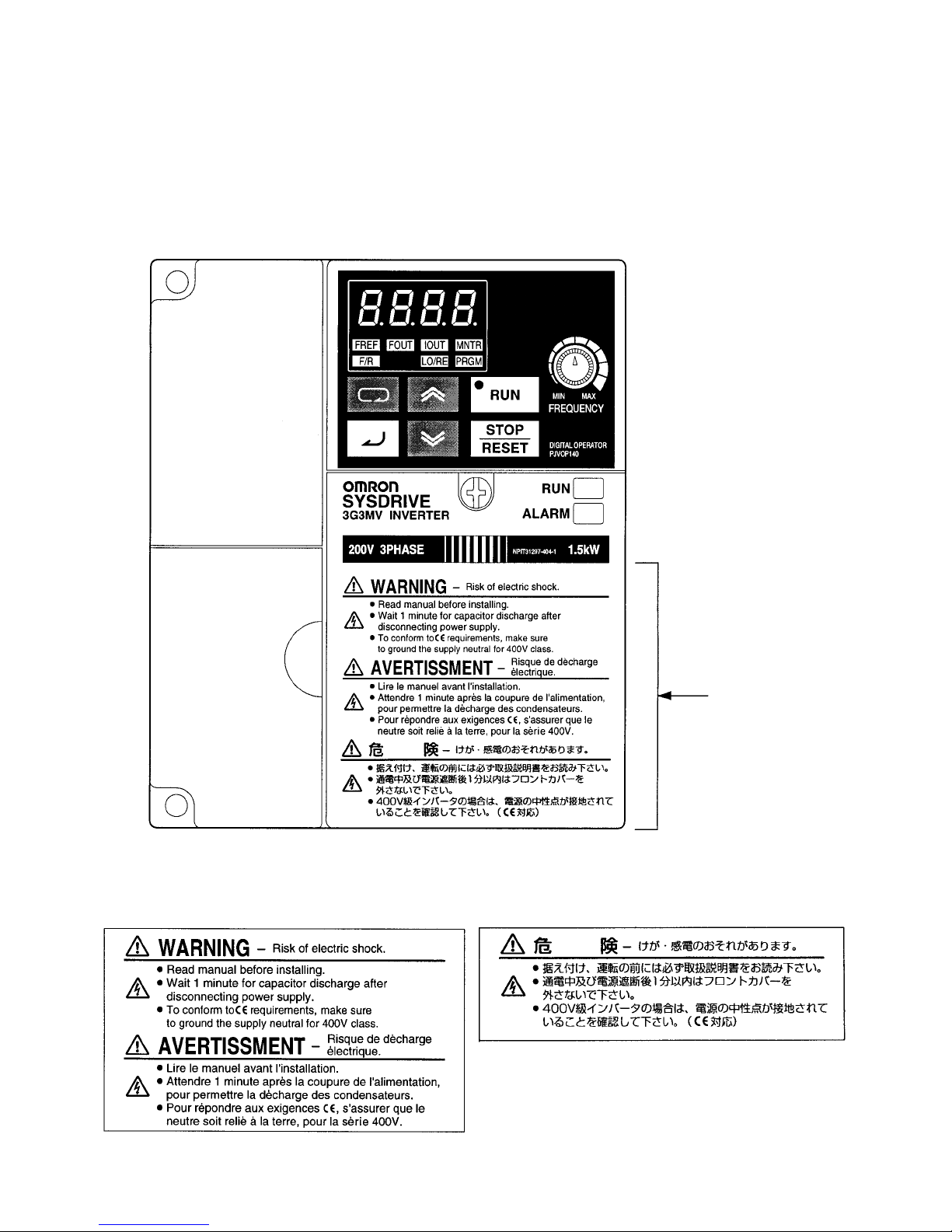
Warning Labels
Warning labels are pasted on the product as shown in the following illustration. Be sure to
follow the instructions given there.
H Warning Labels
H Contents of Warning
Warning label
Checking Before Unpacking
H Checking the Product
On delivery, always check that the delivered product is the SYSDRIVE 3G3MV Inverter that you
ordered.
Should you find any problems with the product, immediately contact your nearest local sales
representative.
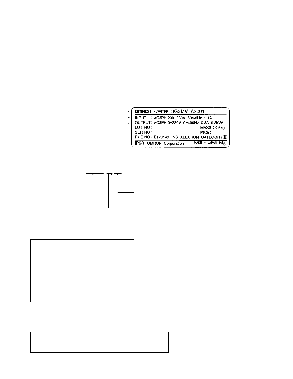
D Checking the Nameplate
Inverter model
Input specifications
Output specifications
D Checking the Model
3G3MV-A4007
Maximum applicable motor capacity
Voltage class
Installation type
Series name: 3G3MV Series
Maximum Applicable Motor Capacity
001 0.1 (0.1) kW
002 0.25/0.37 (0.2) kW
004 0.55 (0.4) kW
007 1.1 (0.75) kW
015 1.5 (1.5) kW
022 2.2 (2.2) kW
037 3.7 (3.7) kW
055 5.5 (5.5) kW
075 7.5 (7.5) kW
Note The figures in parentheses indicate capacities for motors used in Japan.
Voltage Class
2 Three-phase 200-V AC input (200-V class)
B Single-phase 200-V AC input (200-V class)
4 Three-phase 400-V AC input (400-V class)

Installation Type
A Panel-mounting (IP10 min.) or closed wall-mounting models
C Closed wall-mounting models
(NEMA1 type for North America)
Note A-type models with 5.5-KW and 7.5-KW capacity also have NEMA1 enclosure ratings.
D Checking for Damage
Check the overall appearance and check for damage or scratches resulting from transportation.
H Checking the Accessories
Note that this manual is the only accessory provided with the 3G3MV. Set screws and other necessary
parts must be provided by the user.

Read and Understand this Manual
Please read and understand this manual before using the product. Please consult your OMRON
representative if you have any questions or comments.
Warranty and Limitations of Liability
WARRANTY
OMRON’s exclusive warranty is that the products are free from defects in materials and workmanship for
a period of one year (or other period if specified) from date of sale by OMRON.
OMRON MAKES NO WARRANTY OR REPRESENTATION, EXPRESS OR IMPLIED, REGARDING
NON-INFRINGEMENT, MERCHANTABILITY, OR FITNESS FOR PARTICULAR PURPOSE OF THE
PRODUCTS. ANY BUYER OR USER ACKNOWLEDGES THAT THE BUYER OR USER ALONE HAS
DETERMINED THAT THE PRODUCTS WILL SUITABLY MEET THE REQUIREMENTS OF THEIR
INTENDED USE. OMRON DISCLAIMS ALL OTHER WARRANTIES, EXPRESS OR IMPLIED.
LIMITATIONS OF LIABILITY
OMRON SHALL NOT BE RESPONSIBLE FOR SPECIAL, INDIRECT, OR CONSEQUENTIAL
DAMAGES, LOSS OF PROFITS OR COMMERCIAL LOSS IN ANY WAY CONNECTED WITH THE
PRODUCTS, WHETHER SUCH CLAIM IS BASED ON CONTRACT, WARRANTY, NEGLIGENCE, OR
STRICT LIABILITY.
In no event shall the responsibility of OMRON for any act exceed the individual price of the product on
which liability is asserted.
IN NO EVENT SHALL OMRON BE RESPONSIBLE FOR WARRANTY, REPAIR, OR OTHER CLAIMS
REGARDING THE PRODUCTS UNLESS OMRON’S ANALYSIS CONFIRMS THAT THE PRODUCTS
WERE PROPERLY HANDLED, STORED, INSTALLED, AND MAINTAINED AND NOT SUBJECT TO
CONTAMINATION, ABUSE, MISUSE, OR INAPPROPRIATE MODIFICATION OR REPAIR.

Application Considerations
SUITABILITY FOR USE
OMRON shall not be responsible for conformity with any standards, codes, or regulations that apply to
the combination of products in the customer’s application or use of the products.
At the customer’s request, OMRON will provide applicable third party certification documents identifying
ratings and limitations of use that apply to the products. This information by itself is not sufficient for a
complete determination of the suitability of the products in combination with the end product, machine,
system, or other application or use.
The following are some examples of applications for which particular attention must be given. This is not
intended to be an exhaustive list of all possible uses of the products, nor is it intended to imply that the
uses listed may be suitable for the products:
• Outdoor use, uses involving potential chemical contamination or electrical interference, or conditions
or uses not described in this manual.
• Nuclear energy control systems, combustion systems, railroad systems, aviation systems, medical
equipment, amusement machines, vehicles, safety equipment, and installations subject to separate
industry or government regulations.
• Systems, machines, and equipment that could present a risk to life or property.
Please know and observe all prohibitions of use applicable to the products.
NEVER USE THE PRODUCTS FOR AN APPLICATION INVOLVING SERIOUS RISK TO LIFE OR
PROPERTY WITHOUT ENSURING THAT THE SYSTEM AS A WHOLE HAS BEEN DESIGNED TO
ADDRESS THE RISKS, AND THAT THE OMRON PRODUCTS ARE PROPERLY RATED AND
INSTALLED FOR THE INTENDED USE WITHIN THE OVERALL EQUIPMENT OR SYSTEM.
PROGRAMMABLE PRODUCTS
OMRON shall not be responsible for the user’s programming of a programmable product, or any
consequence thereof.

Disclaimers
CHANGE IN SPECIFICATIONS
Product specifications and accessories may be changed at any time based on improvements and other
reasons.
It is our practice to change model numbers when published ratings or features are changed, or when
significant construction changes are made. However, some specifications of the products may be
changed without any notice. When in doubt, special model numbers may be assigned to fix or establish
key specifications for your application on your request. Please consult with your OMRON representative
at any time to confirm actual specifications of purchased products.
DIMENSIONS AND WEIGHTS
Dimensions and weights are nominal and are not to be used for manufacturing purposes, even when
tolerances are shown.
PERFORMANCE DATA
Performance data given in this manual is provided as a guide for the user in determining suitability and
does not constitute a warranty. It may represent the result of OMRON’s test conditions, and the users
must correlate it to actual application requirements. Actual performance is subject to the OMRON
Warranty and Limitations of Liability.
ERRORS AND OMISSIONS
The information in this manual has been carefully checked and is believed to be accurate; however, no
responsibility is assumed for clerical, typographical, or proofreading errors, or omissions.

About this Manual
This manual is divided into the chapters described in the following table. Information is organized by
application area to enable you to use the manual more efficiently.
Chapter Contents
Chapter 1 Overview Describes features and nomenclature.
Chapter 2 Design Provides dimensions, installation methods, wiring methods, peripheral
device design information, and peripheral device selection information.
Chapter 3 Preparing for Operation
and Monitoring
Chapter 4 Test Run Describes the method for controlling a motor through the frequency
Chapter 5 Basic Operation Describes basic Inverter control functions for users not familiar with
Chapter 6 Advanced Operation Describes all of the functions provided by the Inverter. These functions
Chapter 7 Communications Describes the general-purpose RS-422/RS-485 communications
Chapter 8 Maintenance Operations Provides maintenance, inspection, and troubleshooting information.
Chapter 9 Specifications Provides Inverter specifications, as well as the specifications and
Chapter 10 List of Parameters Lists basic information on Inverter parameters as a reference for users
Chapter 11 Using the Inverter for a
Motor
Describes nomenclature and Digital Operator procedures for operating
and monitoring Inverters. Data copying and other functions are
described.
adjuster on the front of the Inverter. This can be used for trial
operation of the system.
Inverters. The functions that must be understood to drive a motor with
an Inverter are described.
will enable more advanced applications, and includes functions that
will improve motor control through the Inverter, such as
responsiveness (torque characteristics), increasing speed accuracy,
PID control, overtorque detection, and other functions.
functions provided by the Inverter, including connection methods and
sample programming for SYSMAC Programmable Controllers.
dimensions of peripheral devices.
already familiar with Inverter operation. Parameters are listed in order
with the page numbers of further information for easy reference.
Describes information on using the Inverter for a motor.

Terms and Conditions of Sale
1. Offer; Acceptance. These terms and conditions (these "Terms") are deemed
part of all quotes, agreements, purchase orders, acknowledgments, price lists,
catalogs, manuals, brochures and other documents, whether electronic or in
writing, relating to the sale of products or services (collectively, the "Products
by Omron Electronics LLC and its subsidiary companies (“Omron”). Omron
objects to any terms or conditions proposed in Buyer’s purchase order or other
documents which are inconsistent with, or in addition to, these Terms.
2. Prices; Payment Terms.
out notice by Omron. Omron reserves the right to increase or decrease prices
on any unshipped portions of outstanding orders. Payments for Products are
due net 30 days unless otherwise stated in the invoice.
3. Discounts.
sent to Buyer after deducting transportation charges, taxes and duties, and will
be allowed only if (i) the invoice is paid according to Omron’s payment terms
and (ii) Buyer has no past due amounts.
4. Interest.
the maximum legal rate, whichever is less, on any balance not paid within the
stated terms.
5. Orders
6. Governmental Approvals.
costs involved in, obtaining any government approvals required for the importation or sale of the Products.
7. Taxes
real property and income taxes), including any interest or penalties thereon,
imposed directly or indirectly on Omron or required to be collected directly or
indirectly by Omron for the manufacture, production, sale, delivery, importation, consumption or use of the Products sold hereunder (including customs
duties and sales, excise, use, turnover and license taxes) shall be charged to
and remitted by Buyer to Omron.
8. Financial.
to Omron, Omron reserves the right to stop shipments or require satisfactory
security or payment in advance. If Buyer fails to make payment or otherwise
comply with these Terms or any related agreement, Omron may (without liability and in addition to other remedies) cancel any unshipped portion of Products sold hereunder and stop any Products in transit until Buyer pays all
amounts, including amounts payable hereunder, whether or not then due,
which are owing to it by Buyer. Buyer shall in any event remain liable for all
unpaid accounts.
9. Cancellation; Etc.
unless Buyer indemnifies Omron against all related costs or expenses.
10. Force Majeure
resulting from causes beyond its control, including earthquakes, fires, floods,
strikes or other labor disputes, shortage of labor or materials, accidents to
machinery, acts of sabotage, riots, delay in or lack of transportation or the
requirements of any government authority.
11. Shipping; Delivery.
a. Shipments shall be by a carrier selected by Omron; Omron will not drop ship
b. Such carrier shall act as the agent of Buyer and delivery to such carrier shall
c. All sales and shipments of Products shall be FOB shipping point (unless oth-
d. Delivery and shipping dates are estimates only; and
e. Omron will package Products as it deems proper for protection against nor-
12. Claims.
Products occurring before delivery to the carrier must be presented in writing
to Omron within 30 days of receipt of shipment and include the original transportation bill signed by the carrier noting that the carrier received the Products
from Omron in the condition claimed.
13. Warranties
Products will be free from defects in materials and workmanship for a period of
twelve months from the date of sale by Omron (or such other period expressed
in writing by Omron). Omron disclaims all other warranties, express or implied.
(b) Limitations
EXPRESS OR IMPLIED, ABOUT NON-INFRINGEMENT, MERCHANTABIL-
Cash discounts, if any, will apply only on the net amount of invoices
Omron, at its option, may charge Buyer 1-1/2% interest per month or
. Omron will accept no order less than $200 net billing.
. All taxes, duties and other governmental charges (other than general
If the financial position of Buyer at any time becomes unsatisfactory
except in “break down” situations.
constitute delivery to Buyer;
erwise stated in writing by Omron), at which point title and risk of loss shall
pass from Omron to Buyer; provided that Omron shall retain a security interest in the Products until the full purchase price is paid;
mal handling and extra charges apply to special conditions.
Any claim by Buyer against Omron for shortage or damage to the
. (a) Exclusive Warranty. Omron’s exclusive warranty is that the
All prices stated are current, subject to change with-
Buyer shall be responsible for, and shall bear all
Orders are not subject to rescheduling or cancellation
. Omron shall not be liable for any delay or failure in delivery
Unless otherwise expressly agreed in writing by Omron:
. OMRON MAKES NO WARRANTY OR REPRESENTATION,
ITY OR FITNESS FOR A PARTICULAR PURPOSE OF THE PRODUCTS.
BUYER ACKNOWLEDGES THAT IT ALONE HAS DETERMINED THAT THE
PRODUCTS WILL SUITABLY MEET THE REQUIREMENTS OF THEIR
")
INTENDED USE. Omron further disclaims all warranties and responsibility of
any type for claims or expenses based on infringement by the Products or otherwise of any intellectual property right. (c) Buyer Remedy
gation hereunder shall be, at Omron’s election, to (i) replace (in the form
originally shipped with Buyer responsible for labor charges for removal or
replacement thereof) the non-complying Product, (ii) repair the non-complying
Product, or (iii) repay or credit Buyer an amount equal to the purchase price of
the non-complying Product; provided that in no event shall Omron be responsible for warranty, repair, indemnity or any other claims or expenses regarding
the Products unless Omron’s analysis confirms that the Products were properly handled, stored, installed and maintained and not subject to contamination, abuse, misuse or inappropriate modification. Return of any Products by
Buyer must be approved in writing by Omron before shipment. Omron Companies shall not be liable for the suitability or unsuitability or the results from the
use of Products in combination with any electrical or electronic components,
circuits, system assemblies or any other materials or substances or environments. Any advice, recommendations or information given orally or in writing,
are not to be construed as an amendment or addition to the above warranty.
See http://oeweb.omron.com or contact your Omron representative for published information.
14. Limitation on Liability; Etc
FOR SPECIAL, INDIRECT, INCIDENTAL, OR CONSEQUENTIAL DAMAGES,
LOSS OF PROFITS OR PRODUCTION OR COMMERCIAL LOSS IN ANY
WAY CONNECTED WITH THE PRODUCTS, WHETHER SUCH CLAIM IS
BASED IN CONTRACT, WARRANTY, NEGLIGENCE OR STRICT LIABILITY.
Further, in no event shall liability of Omron Companies exceed the individual
price of the Product on which liability is asserted.
15. Indemnities
their employees from and against all liabilities, losses, claims, costs and
expenses (including attorney's fees and expenses) related to any claim, investigation, litigation or proceeding (whether or not Omron is a party) which arises
or is alleged to arise from Buyer's acts or omissions under these Terms or in
any way with respect to the Products. Without limiting the foregoing, Buyer (at
its own expense) shall indemnify and hold harmless Omron and defend or settle any action brought against such Companies to the extent based on a claim
that any Product made to Buyer specifications infringed intellectual property
rights of another party.
16. Property; Confidentiality.
sive property of Omron Companies and Buyer shall not attempt to duplicate it
in any way without the written permission of Omron. Notwithstanding any
charges to Buyer for engineering or tooling, all engineering and tooling shall
remain the exclusive property of Omron. All information and materials supplied
by Omron to Buyer relating to the Products are confidential and proprietary,
and Buyer shall limit distribution thereof to its trusted employees and strictly
prevent disclosure to any third party.
17. Export Controls.
licenses regarding (i) export of products or information; (iii) sale of products to
“forbidden” or other proscribed persons; and (ii) disclosure to non-citizens of
regulated technology or information.
18. Miscellaneous
and no course of dealing between Buyer and Omron shall operate as a waiver
of rights by Omron. (b) Assignment
without Omron's written consent. (c) Law.
law of the jurisdiction of the home office of the Omron company from which
Buyer is purchasing the Products (without regard to conflict of law principles). (d) Amendment
Buyer and Omron relating to the Products, and no provision may be changed
or waived unless in writing signed by the parties. (e) Severability
sion hereof is rendered ineffective or invalid, such provision shall not invalidate
any other provision. (f) Setoff
against the amount owing in respect of this invoice. (g) Definitions
herein, “including” means “including without limitation”; and “Omron Companies” (or similar words) mean Omron Corporation and any direct or indirect
subsidiary or affiliate thereof.
. Buyer shall indemnify and hold harmless Omron Companies and
Buyer shall comply with all applicable laws, regulations and
. (a) Waiver. No failure or delay by Omron in exercising any right
. OMRON COMPANIES SHALL NOT BE LIABLE
Any intellectual property in the Products is the exclu-
. Buyer may not assign its rights hereunder
These Terms are governed by the
. These Terms constitute the entire agreement between
. Buyer shall have no right to set off any amounts
. Omron’s sole obli-
. If any provi-
. As used
Certain Precautions on Specifications and Use
1. Suitability of Use. Omron Companies shall not be responsible for conformity
with any standards, codes or regulations which apply to the combination of the
Product in the Buyer’s application or use of the Product. At Buyer’s request,
Omron will provide applicable third party certification documents identifying
ratings and limitations of use which apply to the Product. This information by
itself is not sufficient for a complete determination of the suitability of the Product in combination with the end product, machine, system, or other application
or use. Buyer shall be solely responsible for determining appropriateness of
the particular Product with respect to Buyer’s application, product or system.
Buyer shall take application responsibility in all cases but the following is a
non-exhaustive list of applications for which particular attention must be given:
(i) Outdoor use, uses involving potential chemical contamination or electrical
interference, or conditions or uses not described in this document.
(ii) Use in consumer products or any use in significant quantities.
(iii) Energy control systems, combustion systems, railroad systems, aviation
systems, medical equipment, amusement machines, vehicles, safety equipment, and installations subject to separate industry or government regulations.
(iv) Systems, machines and equipment that could present a risk to life or property. Please know and observe all prohibitions of use applicable to this Product.
NEVER USE THE PRODUCT FOR AN APPLICATION INVOLVING SERIOUS
RISK TO LIFE OR PROPERTY OR IN LARGE QUANTITIES WITHOUT
ENSURING THAT THE SYSTEM AS A WHOLE HAS BEEN DESIGNED TO
ADDRESS THE RISKS, AND THAT THE OMRON’S PRODUCT IS PROPERLY RATED AND INSTALLED FOR THE INTENDED USE WITHIN THE
OVERALL EQUIPMENT OR SYSTEM.
2. Programmable Products.
user’s programming of a programmable Product, or any consequence thereof.
3. Performance Data
and other materials is provided as a guide for the user in determining suitability and does not constitute a warranty. It may represent the result of Omron’s
test conditions, and the user must correlate it to actual application requirements. Actual performance is subject to the Omron’s Warranty and Limitations
of Liability.
4. Change in Specifications
changed at any time based on improvements and other reasons. It is our practice to change part numbers when published ratings or features are changed,
or when significant construction changes are made. However, some specifications of the Product may be changed without any notice. When in doubt, special part numbers may be assigned to fix or establish key specifications for
your application. Please consult with your Omron’s representative at any time
to confirm actual specifications of purchased Product.
5. Errors and Omissions.
checked and is believed to be accurate; however, no responsibility is assumed
for clerical, typographical or proofreading errors or omissions.
Omron Companies shall not be responsible for the
. Data presented in Omron Company websites, catalogs
. Product specifications and accessories may be
Information presented by Omron Companies has been


Table of Contents
Chapter 1. Overview 1-1. . . . . . . . . . . . . . . . . . . . . . . . . . . . . . . . . . . . . . . .
1-1 Functions 1-2. . . . . . . . . . . . . . . . . . . . . . . . . . . . . . . . . . . . . . . . . . . . . . . . . . . . . . . . . . . . . . . . . .
1-2 Nomenclature 1-5. . . . . . . . . . . . . . . . . . . . . . . . . . . . . . . . . . . . . . . . . . . . . . . . . . . . . . . . . . . . . . .
1-3 New Features 1-8. . . . . . . . . . . . . . . . . . . . . . . . . . . . . . . . . . . . . . . . . . . . . . . . . . . . . . . . . . . . . . .
Chapter 2. Design 2-1. . . . . . . . . . . . . . . . . . . . . . . . . . . . . . . . . . . . . . . . . .
2-1 Installation 2-2. . . . . . . . . . . . . . . . . . . . . . . . . . . . . . . . . . . . . . . . . . . . . . . . . . . . . . . . . . . . . . . . .
2-1-1 Dimensions 2-2. . . . . . . . . . . . . . . . . . . . . . . . . . . . . . . . . . . . . . . . . . . . . . . . . . . . . . . . . .
2-1-2 Installation Conditions 2-6. . . . . . . . . . . . . . . . . . . . . . . . . . . . . . . . . . . . . . . . . . . . . . . . .
2-1-3 Removing and Mounting the Covers 2-8. . . . . . . . . . . . . . . . . . . . . . . . . . . . . . . . . . . . . .
2-2 Wiring 2-11. . . . . . . . . . . . . . . . . . . . . . . . . . . . . . . . . . . . . . . . . . . . . . . . . . . . . . . . . . . . . . . . . . . .
2-2-1 Terminal Block 2-12. . . . . . . . . . . . . . . . . . . . . . . . . . . . . . . . . . . . . . . . . . . . . . . . . . . . . . .
2-2-2 Standard Connections 2-20. . . . . . . . . . . . . . . . . . . . . . . . . . . . . . . . . . . . . . . . . . . . . . . . . .
2-2-3 Wiring around the Main Circuit 2-21. . . . . . . . . . . . . . . . . . . . . . . . . . . . . . . . . . . . . . . . . .
2-2-4 Wiring Control Circuit Terminals 2-34. . . . . . . . . . . . . . . . . . . . . . . . . . . . . . . . . . . . . . . . .
2-2-5 Conforming to EC Directives 2-36. . . . . . . . . . . . . . . . . . . . . . . . . . . . . . . . . . . . . . . . . . . .
Chapter 3. Preparing for Operation and Monitoring 3-1. . . . . . . . . . . . .
3-1 Nomenclature 3-2. . . . . . . . . . . . . . . . . . . . . . . . . . . . . . . . . . . . . . . . . . . . . . . . . . . . . . . . . . . . . . .
3-1-1 Names of Parts and their Functions 3-2. . . . . . . . . . . . . . . . . . . . . . . . . . . . . . . . . . . . . . .
3-1-2 Outline of Operation 3-4. . . . . . . . . . . . . . . . . . . . . . . . . . . . . . . . . . . . . . . . . . . . . . . . . . .
3-2 Parameter Copy and Verify Function 3-10. . . . . . . . . . . . . . . . . . . . . . . . . . . . . . . . . . . . . . . . . . . .
3-2-1 Parameter for Copying and Verifying Set Values 3-10. . . . . . . . . . . . . . . . . . . . . . . . . . . . .
3-2-2 Parameter Copying Procedure 3-11. . . . . . . . . . . . . . . . . . . . . . . . . . . . . . . . . . . . . . . . . . .
3-2-3 Parameter Read-prohibit Selection (Prohibiting Data Written to the EEPROM of
the Digital Operator) 3-17. . . . . . . . . . . . . . . . . . . . . . . . . . . . . . . . . . . . . . . . . . . . . . . . . . .
3-2-4 Parameter Copy or Verify Errors 3-18. . . . . . . . . . . . . . . . . . . . . . . . . . . . . . . . . . . . . . . . .
Chapter 4. Test Run 4-1. . . . . . . . . . . . . . . . . . . . . . . . . . . . . . . . . . . . . . . .
4-1 Procedure for Test Run 4-3. . . . . . . . . . . . . . . . . . . . . . . . . . . . . . . . . . . . . . . . . . . . . . . . . . . . . . .
4-2 Operation Example 4-5. . . . . . . . . . . . . . . . . . . . . . . . . . . . . . . . . . . . . . . . . . . . . . . . . . . . . . . . . .
Chapter 5. Basic Operation 5-1. . . . . . . . . . . . . . . . . . . . . . . . . . . . . . . . . .
5-1 Initial Settings 5-2. . . . . . . . . . . . . . . . . . . . . . . . . . . . . . . . . . . . . . . . . . . . . . . . . . . . . . . . . . . . . .
5-1-1 Setting the Parameter Write-prohibit Selection/Parameter Initialization (n001) 5-2. . . .
5-1-2 Setting the Control Mode (n002) 5-3. . . . . . . . . . . . . . . . . . . . . . . . . . . . . . . . . . . . . . . . .
5-2 Operation in Vector Control 5-5. . . . . . . . . . . . . . . . . . . . . . . . . . . . . . . . . . . . . . . . . . . . . . . . . . .
5-3 Operation in V/f Control 5-7. . . . . . . . . . . . . . . . . . . . . . . . . . . . . . . . . . . . . . . . . . . . . . . . . . . . . .
5-3-1 Setting the Rated Motor Current (n036) 5-7. . . . . . . . . . . . . . . . . . . . . . . . . . . . . . . . . . . .
5-3-2 Setting the V/f Patterns (n011 to n017) 5-7. . . . . . . . . . . . . . . . . . . . . . . . . . . . . . . . . . . .
5-4 Setting the Local/Remote Mode 5-9. . . . . . . . . . . . . . . . . . . . . . . . . . . . . . . . . . . . . . . . . . . . . . . .
5-5 Selecting the Operation Command 5-10. . . . . . . . . . . . . . . . . . . . . . . . . . . . . . . . . . . . . . . . . . . . . .
5-6 Setting the Frequency Reference 5-11. . . . . . . . . . . . . . . . . . . . . . . . . . . . . . . . . . . . . . . . . . . . . . . .
5-6-1 Selecting the Frequency Reference 5-11. . . . . . . . . . . . . . . . . . . . . . . . . . . . . . . . . . . . . . .
5-6-2 Upper and Lower Frequency Reference Limits 5-12. . . . . . . . . . . . . . . . . . . . . . . . . . . . . .
5-6-3 Frequency Referencing by Analog Input 5-13. . . . . . . . . . . . . . . . . . . . . . . . . . . . . . . . . . .
5-6-4 Setting Frequency References through Key Sequences 5-18. . . . . . . . . . . . . . . . . . . . . . . .
5-6-5 Setting Frequency References by Pulse Train Input 5-23. . . . . . . . . . . . . . . . . . . . . . . . . .

Table of Contents
5-7 Setting the Acceleration/Deceleration Time 5-25. . . . . . . . . . . . . . . . . . . . . . . . . . . . . . . . . . . . . . .
5-8 Selecting the Reverse Rotation-prohibit 5-28. . . . . . . . . . . . . . . . . . . . . . . . . . . . . . . . . . . . . . . . . .
5-9 Selecting the Stopping Method 5-29. . . . . . . . . . . . . . . . . . . . . . . . . . . . . . . . . . . . . . . . . . . . . . . . .
5-10 Multi-function I/O 5-30. . . . . . . . . . . . . . . . . . . . . . . . . . . . . . . . . . . . . . . . . . . . . . . . . . . . . . . . . . .
5-10-1 Multi-function Input 5-30. . . . . . . . . . . . . . . . . . . . . . . . . . . . . . . . . . . . . . . . . . . . . . . . . . .
5-10-2 Multi-function Output 5-36. . . . . . . . . . . . . . . . . . . . . . . . . . . . . . . . . . . . . . . . . . . . . . . . . .
5-11 Multi-function Analog Output and Pulse Monitor Output 5-38. . . . . . . . . . . . . . . . . . . . . . . . . . . .
5-11-1 Setting the Multi-function Analog Output (n065 through n067) 5-38. . . . . . . . . . . . . . . . .
5-11-2 Setting the Pulse Monitor Output (n065 and n150) 5-39. . . . . . . . . . . . . . . . . . . . . . . . . . .
Chapter 6. Advanced Operation 6-1. . . . . . . . . . . . . . . . . . . . . . . . . . . . . .
6-1 Precise Vector Control Settings and Adjustments 6-2. . . . . . . . . . . . . . . . . . . . . . . . . . . . . . . . . . .
6-1-1 Precise Vector Control Settings 6-2. . . . . . . . . . . . . . . . . . . . . . . . . . . . . . . . . . . . . . . . . .
6-1-2 Adjusting Output Torque in Vector Control 6-3. . . . . . . . . . . . . . . . . . . . . . . . . . . . . . . . .
6-2 Energy-saving Control 6-5. . . . . . . . . . . . . . . . . . . . . . . . . . . . . . . . . . . . . . . . . . . . . . . . . . . . . . . .
6-2-1 Energy-saving Control Operation 6-5. . . . . . . . . . . . . . . . . . . . . . . . . . . . . . . . . . . . . . . . .
6-2-2 Performing Energy-saving Settings 6-6. . . . . . . . . . . . . . . . . . . . . . . . . . . . . . . . . . . . . . .
6-3 PID Control 6-11. . . . . . . . . . . . . . . . . . . . . . . . . . . . . . . . . . . . . . . . . . . . . . . . . . . . . . . . . . . . . . . .
6-3-1 PID Control Applications 6-11. . . . . . . . . . . . . . . . . . . . . . . . . . . . . . . . . . . . . . . . . . . . . . .
6-3-2 PID Control Operation 6-12. . . . . . . . . . . . . . . . . . . . . . . . . . . . . . . . . . . . . . . . . . . . . . . . .
6-3-3 Types of PID Control 6-12. . . . . . . . . . . . . . . . . . . . . . . . . . . . . . . . . . . . . . . . . . . . . . . . . .
6-3-4 Block Diagram of PID Control 6-14. . . . . . . . . . . . . . . . . . . . . . . . . . . . . . . . . . . . . . . . . . .
6-3-5 Input Selection of PID Control Target Value and Detection Value 6-15. . . . . . . . . . . . . . .
6-3-6 PID Control Settings 6-16. . . . . . . . . . . . . . . . . . . . . . . . . . . . . . . . . . . . . . . . . . . . . . . . . . .
6-3-7 PID Adjustments 6-19. . . . . . . . . . . . . . . . . . . . . . . . . . . . . . . . . . . . . . . . . . . . . . . . . . . . . .
6-3-8 PID Fine Tuning 6-21. . . . . . . . . . . . . . . . . . . . . . . . . . . . . . . . . . . . . . . . . . . . . . . . . . . . . .
6-4 Setting the Carrier Frequency 6-23. . . . . . . . . . . . . . . . . . . . . . . . . . . . . . . . . . . . . . . . . . . . . . . . . .
6-5 DC Injection Braking Function 6-26. . . . . . . . . . . . . . . . . . . . . . . . . . . . . . . . . . . . . . . . . . . . . . . . .
6-6 Stall Prevention Function 6-27. . . . . . . . . . . . . . . . . . . . . . . . . . . . . . . . . . . . . . . . . . . . . . . . . . . . .
6-7 Overtorque/Undertorque Detection Function 6-31. . . . . . . . . . . . . . . . . . . . . . . . . . . . . . . . . . . . . .
6-8 Torque Compensation Function 6-35. . . . . . . . . . . . . . . . . . . . . . . . . . . . . . . . . . . . . . . . . . . . . . . . .
6-9 Slip Compensation Function 6-37. . . . . . . . . . . . . . . . . . . . . . . . . . . . . . . . . . . . . . . . . . . . . . . . . . .
6-10 Other Functions 6-39. . . . . . . . . . . . . . . . . . . . . . . . . . . . . . . . . . . . . . . . . . . . . . . . . . . . . . . . . . . . .
6-10-1 Digital Operator Disconnection Error Detection 6-39. . . . . . . . . . . . . . . . . . . . . . . . . . . . .
6-10-2 Motor Protection Functions (n037 and n038) 6-39. . . . . . . . . . . . . . . . . . . . . . . . . . . . . . . .
6-10-3 Cooling Fan Operation Function (n039) 6-40. . . . . . . . . . . . . . . . . . . . . . . . . . . . . . . . . . .
6-10-4 Momentary Power Interruption Compensation (n081) 6-40. . . . . . . . . . . . . . . . . . . . . . . .
6-10-5 Fault Retry (n082) 6-41. . . . . . . . . . . . . . . . . . . . . . . . . . . . . . . . . . . . . . . . . . . . . . . . . . . . .
6-10-6 Frequency Jump Function (n083 to n086) 6-42. . . . . . . . . . . . . . . . . . . . . . . . . . . . . . . . . .
6-10-7 Accumulated Operating Time (n087, n088) 6-43. . . . . . . . . . . . . . . . . . . . . . . . . . . . . . . . .
6-10-8 Frequency Detection 6-44. . . . . . . . . . . . . . . . . . . . . . . . . . . . . . . . . . . . . . . . . . . . . . . . . . .
6-10-9 UP/DOWN Command Frequency Memory (n100) 6-45. . . . . . . . . . . . . . . . . . . . . . . . . . .
6-10-10 Input Open-phase Detection (n166, n167) 6-47. . . . . . . . . . . . . . . . . . . . . . . . . . . . . . . . .
6-10-11 Output Open-phase Detection (n168, n169) 6-47. . . . . . . . . . . . . . . . . . . . . . . . . . . . . . . .
6-10-12 Fault Log (n178) 6-48. . . . . . . . . . . . . . . . . . . . . . . . . . . . . . . . . . . . . . . . . . . . . . . . . . . . .

Table of Contents
Chapter 7. Communications 7-1. . . . . . . . . . . . . . . . . . . . . . . . . . . . . . . . . .
7-1 Inverter Settings 7-2. . . . . . . . . . . . . . . . . . . . . . . . . . . . . . . . . . . . . . . . . . . . . . . . . . . . . . . . . . . . .
7-1-1 Setting the Communications Conditions 7-2. . . . . . . . . . . . . . . . . . . . . . . . . . . . . . . . . . .
7-1-2 RUN Command Selection (n003) 7-5. . . . . . . . . . . . . . . . . . . . . . . . . . . . . . . . . . . . . . . . .
7-1-3 Frequency Reference Input Selection (n004) 7-6. . . . . . . . . . . . . . . . . . . . . . . . . . . . . . . .
7-1-4 Setting the Multi-function Inputs (n050 to n056) 7-6. . . . . . . . . . . . . . . . . . . . . . . . . . . .
7-2 Message Communications Basic Format 7-8. . . . . . . . . . . . . . . . . . . . . . . . . . . . . . . . . . . . . . . . .
7-3 DSR Message and Response 7-11. . . . . . . . . . . . . . . . . . . . . . . . . . . . . . . . . . . . . . . . . . . . . . . . . . .
7-3-1 Data Read (Function Code: 03 Hex) 7-11. . . . . . . . . . . . . . . . . . . . . . . . . . . . . . . . . . . . . .
7-3-2 Data Write/Broadcast Data Write (Function Code: 10 Hex) 7-13. . . . . . . . . . . . . . . . . . . .
7-3-3 Loop-back Test (Function Code: 08 Hex) 7-16. . . . . . . . . . . . . . . . . . . . . . . . . . . . . . . . . .
7-4 Enter Command 7-18. . . . . . . . . . . . . . . . . . . . . . . . . . . . . . . . . . . . . . . . . . . . . . . . . . . . . . . . . . . . .
7-5 Setting the Communications Data 7-19. . . . . . . . . . . . . . . . . . . . . . . . . . . . . . . . . . . . . . . . . . . . . . .
7-6 Register Number Allocations in Detail 7-21. . . . . . . . . . . . . . . . . . . . . . . . . . . . . . . . . . . . . . . . . . .
7-6-1 I/O Function 7-21. . . . . . . . . . . . . . . . . . . . . . . . . . . . . . . . . . . . . . . . . . . . . . . . . . . . . . . . .
7-6-2 Monitor Functions 7-22. . . . . . . . . . . . . . . . . . . . . . . . . . . . . . . . . . . . . . . . . . . . . . . . . . . . .
7-7 Communications Error Codes 7-27. . . . . . . . . . . . . . . . . . . . . . . . . . . . . . . . . . . . . . . . . . . . . . . . . .
7-8 Self-diagnostic Test 7-29. . . . . . . . . . . . . . . . . . . . . . . . . . . . . . . . . . . . . . . . . . . . . . . . . . . . . . . . . .
7-9 Communications with Programmable Controller 7-30. . . . . . . . . . . . . . . . . . . . . . . . . . . . . . . . . . .
7-9-1 Available Programmable Controllers and Peripheral Devices 7-30. . . . . . . . . . . . . . . . . . .
7-9-2 Wiring the Communications Line 7-33. . . . . . . . . . . . . . . . . . . . . . . . . . . . . . . . . . . . . . . .
7-9-3 Outline of Protocol Macro Function 7-34. . . . . . . . . . . . . . . . . . . . . . . . . . . . . . . . . . . . . . .
7-9-4 Creating a Project File 7-38. . . . . . . . . . . . . . . . . . . . . . . . . . . . . . . . . . . . . . . . . . . . . . . . .
7-9-5 Ladder Program 7-47. . . . . . . . . . . . . . . . . . . . . . . . . . . . . . . . . . . . . . . . . . . . . . . . . . . . . .
7-9-6 Communications Response Time 7-51. . . . . . . . . . . . . . . . . . . . . . . . . . . . . . . . . . . . . . . . .
Chapter 8. Maintenance Operations 8-1. . . . . . . . . . . . . . . . . . . . . . . . . . .
8-1 Protective and Diagnostic Functions 8-2. . . . . . . . . . . . . . . . . . . . . . . . . . . . . . . . . . . . . . . . . . . . .
8-1-1 Fault Detection (Fatal Errors) 8-2. . . . . . . . . . . . . . . . . . . . . . . . . . . . . . . . . . . . . . . . . . . .
8-1-2 Warning Detection (Nonfatal Errors) 8-10. . . . . . . . . . . . . . . . . . . . . . . . . . . . . . . . . . . . . .
8-2 Troubleshooting 8-14. . . . . . . . . . . . . . . . . . . . . . . . . . . . . . . . . . . . . . . . . . . . . . . . . . . . . . . . . . . . .
8-2-1 Parameters Fail Set 8-14. . . . . . . . . . . . . . . . . . . . . . . . . . . . . . . . . . . . . . . . . . . . . . . . . . . .
8-2-2 Motor Fails to Operate 8-14. . . . . . . . . . . . . . . . . . . . . . . . . . . . . . . . . . . . . . . . . . . . . . . . .
8-2-3 Motor Rotates in the Wrong Direction 8-16. . . . . . . . . . . . . . . . . . . . . . . . . . . . . . . . . . . . .
8-2-4 Motor Outputs No Torque or Acceleration is Slow 8-16. . . . . . . . . . . . . . . . . . . . . . . . . . .
8-2-5 Speed Accuracy of the Inverter Rotating at High Speed in Vector Control is Low 8-17. .
8-2-6 Motor Deceleration Rate is Low 8-17. . . . . . . . . . . . . . . . . . . . . . . . . . . . . . . . . . . . . . . . .
8-2-7 Vertical-axis Load Drops when Brakes are Applied 8-17. . . . . . . . . . . . . . . . . . . . . . . . . .
8-2-8 Motor Burns 8-18. . . . . . . . . . . . . . . . . . . . . . . . . . . . . . . . . . . . . . . . . . . . . . . . . . . . . . . . .
8-2-9 Controller or AM Radio Receives Noise when Inverter is Started 8-18. . . . . . . . . . . . . . .
8-2-10 Ground Fault Interrupter is Actuated when Inverter is Started 8-18. . . . . . . . . . . . . . . . . .
8-2-11 Mechanical Vibration 8-19. . . . . . . . . . . . . . . . . . . . . . . . . . . . . . . . . . . . . . . . . . . . . . . . . .
8-2-12 Stable PID Control is Not Possible or Control Fails 8-19. . . . . . . . . . . . . . . . . . . . . . . . . .
8-2-13 Inverter Vibration in Energy-saving Control 8-20. . . . . . . . . . . . . . . . . . . . . . . . . . . . . . . .
8-2-14 Motor Rotates after Output of Inverter is Turned OFF 8-20. . . . . . . . . . . . . . . . . . . . . . . .
8-2-15 Detects OV (Over voltage) and Stalls when Motor Starts 8-20. . . . . . . . . . . . . . . . . . . . . .
8-2-16 Output Frequency Does Not Reach Frequency Reference 8-21. . . . . . . . . . . . . . . . . . . . . .
8-2-17 Inverter Does Not Run Because EF
(Simultaneous Inputs of Forward and Reverse Commands) is Detected,
Or Motor Rotates Momentarily When Control Device Power is Turned OFF 8-21. . . . . .
8-3 Maintenance and Inspection 8-22. . . . . . . . . . . . . . . . . . . . . . . . . . . . . . . . . . . . . . . . . . . . . . . . . . .

Table of Contents
Chapter 9. Specifications 9-1. . . . . . . . . . . . . . . . . . . . . . . . . . . . . . . . . . . .
9-1 Inverter Specifications 9-2. . . . . . . . . . . . . . . . . . . . . . . . . . . . . . . . . . . . . . . . . . . . . . . . . . . . . . . .
9-2 Option Specifications 9-7. . . . . . . . . . . . . . . . . . . . . . . . . . . . . . . . . . . . . . . . . . . . . . . . . . . . . . . .
9-2-1 List of Options 9-7. . . . . . . . . . . . . . . . . . . . . . . . . . . . . . . . . . . . . . . . . . . . . . . . . . . . . . .
9-2-2 DeviceNet Communications Unit 9-9. . . . . . . . . . . . . . . . . . . . . . . . . . . . . . . . . . . . . . . . .
9-2-3 Fan Unit 9-10. . . . . . . . . . . . . . . . . . . . . . . . . . . . . . . . . . . . . . . . . . . . . . . . . . . . . . . . . . . .
9-2-4 Scaling Meter 9-11. . . . . . . . . . . . . . . . . . . . . . . . . . . . . . . . . . . . . . . . . . . . . . . . . . . . . . . .
9-2-5 Braking Resistor 9-12. . . . . . . . . . . . . . . . . . . . . . . . . . . . . . . . . . . . . . . . . . . . . . . . . . . . . .
9-2-6 Braking Resistor Unit 9-14. . . . . . . . . . . . . . . . . . . . . . . . . . . . . . . . . . . . . . . . . . . . . . . . . .
9-2-7 DC Reactor 9-15. . . . . . . . . . . . . . . . . . . . . . . . . . . . . . . . . . . . . . . . . . . . . . . . . . . . . . . . . .
9-2-8 DIN Track Mounting Bracket 9-16. . . . . . . . . . . . . . . . . . . . . . . . . . . . . . . . . . . . . . . . . . . .
9-2-9 Digital Operators 9-17. . . . . . . . . . . . . . . . . . . . . . . . . . . . . . . . . . . . . . . . . . . . . . . . . . . . . .
9-2-10 AC Reactor 9-20. . . . . . . . . . . . . . . . . . . . . . . . . . . . . . . . . . . . . . . . . . . . . . . . . . . . . . . . . .
9-2-11 EMC-compatible Noise Filter 9-22. . . . . . . . . . . . . . . . . . . . . . . . . . . . . . . . . . . . . . . . . . .
9-2-12 Simple Input Noise Filter and Input Noise Filter 9-30. . . . . . . . . . . . . . . . . . . . . . . . . . . . .
9-2-13 Output Noise Filter 9-32. . . . . . . . . . . . . . . . . . . . . . . . . . . . . . . . . . . . . . . . . . . . . . . . . . . .
Chapter 10. List of Parameters 10-1. . . . . . . . . . . . . . . . . . . . . . . . . . . . . .
Chapter 11. Using the Inverter for a Motor 11-1. . . . . . . . . . . . . . . . . . . . .
Revision History R-1. . . . . . . . . . . . . . . . . . . . . . . . . . . . . . . . .

Overview
1-1 Functions
1-2 Nomenclature
1-3 New Features
1
Chapter 1

p
g
gp
g
p
g
Overview Chapter 1
1-1 Functions
The multi-function compact SYSDRIVE 3G3MV-Series Inverter is the first compact
Inverter to feature open-loop vector control.
The 3G3MV Inverter meets EC Directives and UL/cUL standard requirements for worldwide use.
Furthermore, the 3G3MV-Series Inverter incorporates a variety of convenient control,
network, and I/O functions that are versatile and easy-to-use.
H SYSDRIVE 3G3MV Inverter Models
• The following 200-V-class (three- and single-phase 200-V AC types) and 400-V-class (three-phase
400-V AC type) 3G3MV models are available.
Rated voltage Enclosure rating Maximum applied
motor capacity
3-phase 200 V AC Panel-mounting models
(conform to IP20)
Closed wall-mounting
models(conformto
NEMA1 and IP20)
Single-phase 200 V AC Panel-mounting models
(conform to IP20)
3-phase 400 V AC Panel-mounting models
(conform to IP20)
Closed wall-mounting
models(conformto
NEMA1 and IP20)
0.1 (0.1) kW 3G3MV-A2001
0.25 (0.2) kW 3G3MV-A2002
0.55 (0.4) kW 3G3MV-A2004
1.1 (0.75) kW 3G3MV-A2007
1.5 (1.5) kW 3G3MV-A2015
2.2 (2.2) kW 3G3MV-A2022
3.7 (3.7) kW 3G3MV-A2037
5.5 (5.5) kW 3G3MV-A2055
7.5 (7.5) kW 3G3MV-A2075
0.1 (0.1) kW 3G3MV-AB001
0.25 (0.2) kW 3G3MV-AB002
0.55 (0.4) kW 3G3MV-AB004
1.1 (0.75) kW 3G3MV-AB007
1.5 (1.5) kW 3G3MV-AB015
2.2 (2.2) kW 3G3MV-AB022
3.7 (3.7) kW 3G3MV-AB037
0.37 (0.2) kW 3G3MV-A4002
0.55 (0.4) kW 3G3MV-A4004
1.1 (0.75) kW 3G3MV-A4007
1.5 (1.5) kW 3G3MV-A4015
2.2 (2.2) kW 3G3MV-A4022
3.7 (3.7) kW 3G3MV-A4037
5.5 (5.5) kW 3G3MV-A4055
7.5 (7.5) kW 3G3MV-A4075
Model
Note The figures in parentheses indicate capacities for motors used in Japan.
1-2

Overview Chapter 1
H Powerful Torque Ideal for a Variety of Applications
The 3G3MV is OMRON’s first compact Inverter incorporating an open-loop vector control function,
which ensures a torque output that is 150% of the rated motor torque at an output frequency of 1 Hz.
Ensures a more powerful revolution at low frequencies than any conventional inverter. Furthermore, the
3G3MV Inverter suppresses the revolution fluctuation caused by the load.
Incorporates a fully automatic torque boost function that drives the motor powerfully in V/f control.
Incorporates a high-speed current limit function, thus suppressing overcurrent caused by high torque
and ensuring smooth operation of the motor.
H Convenient Easy-to-use Functions
• The FREQUENCY adjuster of the Digital Operator allows easy operation. The default setting is for
operation according to the FREQUENCY adjuster setting.
• The Digital Operator has a parameter copy function ensuring easy parameter control.
• Ease of maintenance is ensured. The cooling fan is easily replaceable. The life of the cooling fan can
be prolonged by turning ON the cooling fan only when the Inverter is in operation.
• Incorporates a control transistor. Therefore, the Inverter will provide powerful control by just connect-
ing a braking resistor.
• Incorporates an inrush current preventive circuit that prevents contact weld at the input power supply
block.
H International Standards (EC Directives and UL/cUL Standards)
The 3G3MV Inverter meets the EC Directives and UL/cUL standard requirements for worldwide use.
Classification Applicable standard
EC Directives
UL/cUL UL508C
EMC directive EN61800-3
Low-voltage directive EN50178
H Compatible with DeviceNet and RS-422/485
• Supports RS-422 and RS-485 communications conforming to the MODBUS Communications Proto-
col, thus making it possible to easily construct networks with the use of the Protocol Macro or ASCII
Unit mounted on an OMRON SYSMAC PLC. The MODBUS Communications Protocol is a trademark
of AEG Schneider Automation.
• Connects to the 3G3MV-PDRT2 DeviceNet Communications Unit. A remote I/O function for Device-
Net communications Unit is available to the 3G3MV Inverter, which ensures ease of communications
just like standard I/O communications.
Furthermore, DeviceNet communications conform to the DeviceNet communications protocol for
open networks, thus allowing construction of multi-vendor networks in which other companies’
devices can coexist.
Note 1. MODBUS communications and DeviceNet communications cannot be performed simulta-
neously. It is necessary to select the type of communications required.
Note 2. Only DeviceNet Communications Units manufactured after January 1st, 2000 can be con-
nected to 5.5-kW and 7.5-kW Inverters. Earlier products are not compatible with these Inverters.
1-3

Overview Chapter 1
H Handles a Variety of I/O Signals
Handles a variety of I/O signals over a wide application range as described below.
• Analog voltage input: 0 to 10 V
• Analog current input: 4 to 20 or 0 to 20 mA
• Pulse train input: 0.1 to 33.0 kHz set with parameter
• Multi-function analog output or pulse train output is selectable as monitor output
H Suppression of Harmonics
Connects to DC reactors, thus suppressing harmonics more effectively than conventional AC reactors.
Further improvement in the suppression of harmonics is possible with the combined use of the DC and
AC reactors.
1-4
Overview Chapter 1
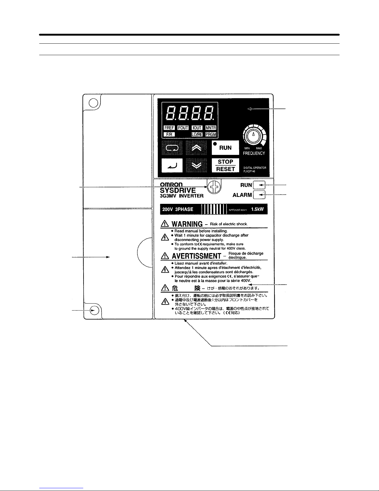
1-2 Nomenclature
H Panel
Digital Operator
Front panel
mounting
screw
Terminal
cover
Four
mounting
holes
RUN indicator
ALARM display
Front cover
Bottom cover
Note None of the following 200-V models have a terminal cover or mounting holes. Instead, the front
cover is used as a terminal cover and two U-shaped cutouts are provided in place of the mounting
holes.
3G3MV-A2001 (0.1 kW), 3G3MV-A2002 (0.2 kW), 3G3MV-A2004 (0.4 kW), and 3G3MV-A2007
(0.75 kW)
3G3MV-AB001 (0.1 kW), 3G3MV-AB002 (0.2 kW), and 3G3MV-AB004 (0.4 kW)
1-5
Overview Chapter 1
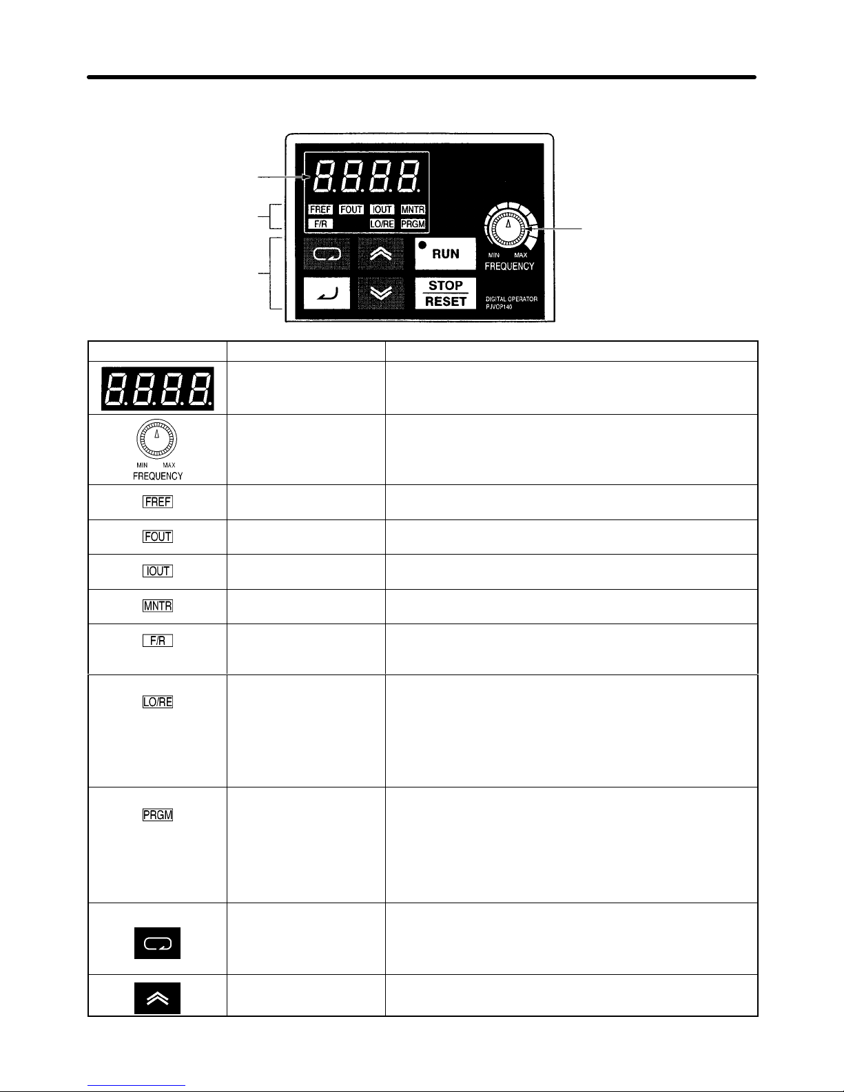
H Digital Operator
Data display
Simplified-LED
indicators
Operation keys
Appearance Name Function
Data display Displays relevant data items, such as frequency reference,
output frequency, and parameter set values.
FREQUENCY adjuster Sets the frequency reference within a range between 0 Hz
and the maximum frequency.
FREF indicator The frequency reference can be monitored or set while this
indicator is lit.
FOUT indicator The output frequency of the Inverter can be monitored
while this indicator is lit.
IOUT indicator The output current of the Inverter can be monitored while
this indicator is lit.
MNTR indicator The values set in U01 through U18 are monitored while
this indicator is lit.
F/R indicator The direction of rotation can be selected while this
indicator is lit when operating the Inverter with the RUN
Key.
LO/RE indicator The operation of the Inverter through the Digital Operator
or according to the set parameters is selectable while this
indicator is lit.
FREQUENCY
adjuster
PRGM indicator The parameters in n001 through n179 can be set or
Mode Key Switches the simplified-LED (setting and monitor) item
Increment Key Increases multi-function monitor numbers, parameter
1-6
Note This status of this indicator can be only monitored
while the Inverter is in operation. Any RUN command
input is ignored while this indicator is lit.
monitored while this indicator is lit.
Note While the Inverter is in operation, the parameters can
be only monitored and only some parameters can be
changed. Any RUN command input is ignored while
this indicator is lit.
indicators in sequence.
Parameter being set will be canceled if this key is pressed
before entering the setting.
numbers, and parameter set values.
Overview Chapter 1
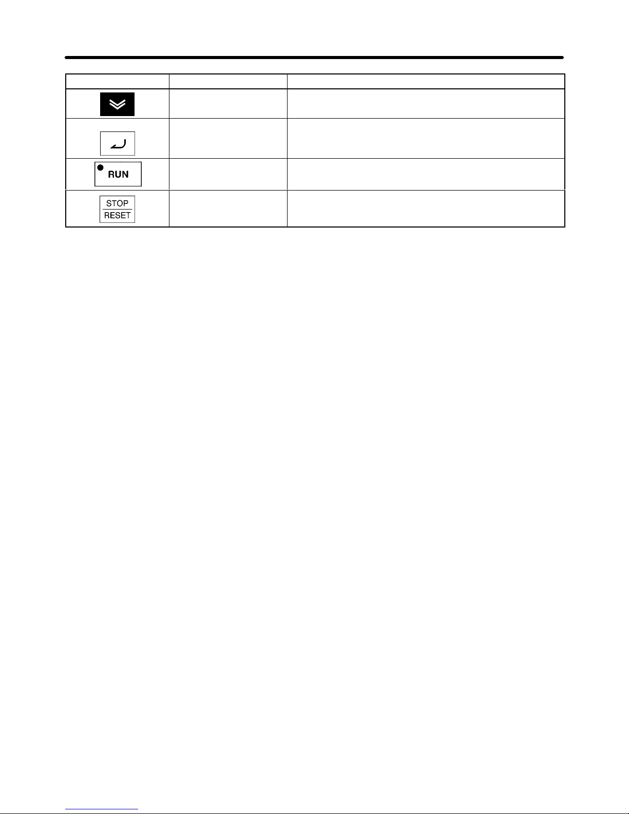
Appearance FunctionName
Decrement Key Decreases multi-function monitor numbers, parameter
numbers, and parameter set values.
Enter Key Enters multi-function monitor numbers, parameter
numbers, and internal data values after they are set or
changed.
RUN Key Starts the Inverter running when the 3G3MV is in operation
with the Digital Operator.
STOP/RESET Key Stops the Inverter unless parameter n007 is set to disable
the STOP Key. Functions as a Reset Key when an Inverter
error occurs. (See note.)
Note For safety reasons, the reset will not work while a RUN command (forward or reverse) is in effect.
Wait until the RUN command is OFF before resetting the Inverter.
1-7

Overview Chapter 1
1-3 New Features
New features have been added to 3G3MV-Series models with 5.5-kW and 7.5-kW capacities (i.e., the 3G3MV-A2055/A2075/ A4055/A4075). These features are outlined
below and explained in detail in Chapter 6.
H New Features for 3G3MV-A2055/A2075/A4055/A4075 Only
D Enclosure Rating: Closed Wall-mounting Conforming to IP20/NEMA1
The 5.5-kW and 7.5-kW Inverters have closed wall-mounting specifications that conform to
IP20/NEMA1, so they can operate in an ambient temperature range of –10 to 40°C.
Note To operate this Inverter within an ambient temperature range of –10 to 50°C, remove the top and
bottom covers to convert it to a panel-mounting model (IP00).
D Default Settings Changed for V/f Patterns (Parameters: n011 to n017)
For 5.5-kW and 7.5-kW Inverters, two of the default settings have been changed. The default settings
for the middle output frequency voltage (VC) (n015) and the minimum output frequency voltage (VMIN
(n017) have both been changed to 10 V for 200-V-class models and to 20 V for 400-V-class models.
D Inverter Overheating Warning Input
(Parameters: n050 to n056; Fault Display: oH3)
An Inverter overheating warning input has been added as a new function that can be set for multi-function inputs 1 to 7 (n050 to n056). When this warning is input, an oH3 fault (nonfatal error) will be displayed. This input can be used for functions such as thermal contact connections for peripheral overheating detection.
D Frequency Reference Loss Detection (Parameter: n064)
When the frequency is referenced using analog frequency reference inputs (0 to 10 V/4 to 20 mA/0 to 20
mA), this function detects sudden changes in analog inputs as errors (disconnection, short circuit,
breakdown, etc.) and outputs the frequency reference loss output that is set in multi-function outputs 1
to 3 (n057 to n059). After the change is detected, operation continues at 80% of the frequency reference
prior to the change.
D Accumulated Operating Time (Monitor: U-13; Parameters: n087, n088)
This function calculates and stores in memory the Inverter’s accumulated power-ON time or RUN time.
Use it for checking and determining the maintenance schedule.
D Speed Search Adjustment (Parameters: n101, n102)
A function has been added for adjusting the speed search. (The speed search is a function for detecting
and smoothly controlling the speed of a free running motor.) The speed search operating time and
search level can be adjusted.
D Input Open-phase Detection
(Parameters: n166, n167; Fault Display: PF)
This function detects the Inverter’s input power supply open phase. Open phases are detected through
main circuit voltage fluctuations, so this function can also be used for detecting abnormal voltage fluctuations in the input power supply voltage.
1-8
 Loading...