

Page 1

USER’S MANUAL
SYSDRIVE 3G3MV
Multi-function Compact Inverter
Cat. No. I527-E2-02
Page 2

Thankyoufor choosing this SYSDRIVE3G3MV-seriesproduct.Properuse
and handling of the product will ensure proper product performance, will
lengthen product life, and may prevent possible accidents.
Please read this manual thoroughly and handle and operate the product
with care.
NOTICE
1. This manual describes the functions of the product and relations with other
products. Youshould assume that anything not described in this manual is
not possible.
2. Although care has been given in documenting the product, please contact
yourOMRON representative if you haveany suggestions on improving this
manual.
3. The product contains potentially dangerous parts under the cover. Do not
attempt to open the cover under any circumstances. Doing so may result in
injuryordeathandmaydamage the product. Never attempt to repair or disassemble the product.
4. We recommend that you add the following precautions to any instruction
manualsyouprepareforthesystemintowhichthe productisbeinginstalled.
S Precautions on the dangers of high-voltage equipment.
S Precautionsontouchingtheterminalsoftheproduct evenafterpowerhas
been turned off. (These terminals are live even with the power turned off.)
5. Specifications and functions may be changed without notice in order to
improve product performance.
Items to Check Before Unpacking
Checkthefollowing items before removingtheproductfrom the package:
S Hasthecorrectproductbeendelivered(i.e., thecorrectmodelnumberand
specifications)?
S Has the product been damaged in shipping?
S Are any screws or bolts loose?
Page 3
Checking Before Unpacking
H Checking the Product
Ondelivery,always check that the delivered productisthe SYSDRIVE 3G3MV Inverter
that you ordered.
Should you find any problems with the product, immediately contact your nearest local
sales representative.
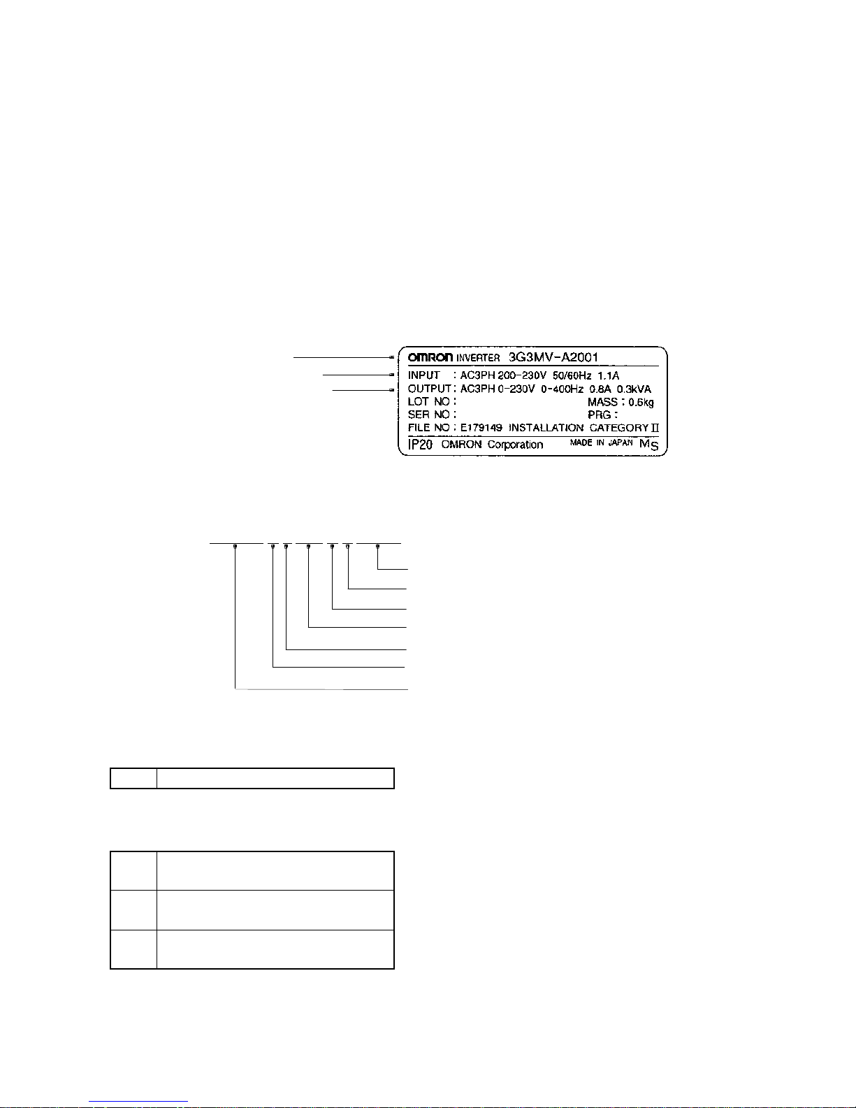
D Checking the Nameplate
Inverter model
Input specifications
Output specifications
D Checking the Model
3G3MV-A 4 007 N Z 00001
Special software option
No Heatsink
No potentiometer
Maximum applicable motor capacity
Voltage class
Installation type
Series name: 3G3MV Series
Installation Type
A Closed wall mounting
Voltage Class
2 Three-phase 200-VAC input
(200-V class)
B Single-phase 200-VAC input
(200-V class)
4 Three-phase 400-VAC input
(400-V class)
Page 4

Maximum Applicable Motor Capacity
001 0.1 (0.1) kW
002 0.2 (0.25/0.37) kW
004 0.4 (0.55) kW
007 0.75 (1.1) kW
015 1.5 (1.5) kW
022 2.2 (2.2) kW
030 3.0 (3.0) kW
040 4.0 (4.0) kW
055 5.5 (5.5) kW
075 7.5 (7.5) kW
Note The figures in parentheses indicate capacities for motors used outside Japan.
Front Cover options
B Blank cover
N No potentiometer
Heatsink option
Z No Heatsink
D Checking for Damage
Checkthe overall appearance and checkfor damage or scratchesresulting from transportation.
Page 5
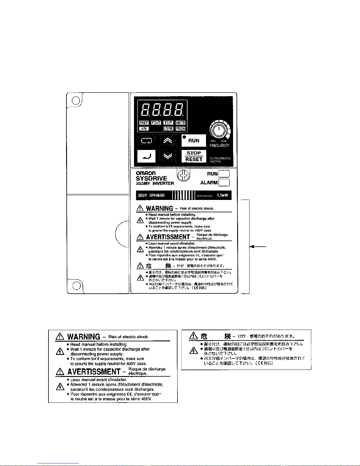
Warning Labels
Warning labels are pasted on the product as shown in the following illustration. Be sure to
follow the instructions given there.
H Warning Labels
Warning label
H Contents of Warning
Page 6

!
!
!
!
!
!
!
!
!
!
!
W ARNING Be sure confirm that the RUN signal is turned OFF before turning ON the power
supply, resetting the alarm, or switching the LOCAL/REMOTE selector. Doing so
while the RUN signal is turned ON may result in injury.
Caution Be sure to confirm permissible ranges of motors and machines before operation
because the Inverter speed can be easily changed from low to high. Not doing so
may result in damage to the product.
Caution Providea separateholding brakewhen necessary.Not doingso may resultin injury.
Caution Donotperformasignalcheckduringoperation. Doingsomayresult ininjuryordam-
age to the product.
Caution Do not carelessly change settings. Doing so may result in injury or damage to the
product.
Maintenance and Inspection Precautions
W ARNING Do not touch the Inverter terminals while the power is being supplied.
W ARNING Maintenance or inspection must be performed only after turning OFF the power
supply, confirming that the CHARGE indicator (or status indicators) is turned OFF,
andafterwaiting for thetimespecified on the frontcover. Notdoing so may result in
electrical shock.
W ARNING Maintenance, inspection, or parts replacement must be performed by authorized
personnel. Not doing so may result in electrical shock or injury.
W ARNING Do not attempt to take the Unit apart or repair. Doing either of these may result in
electrical shock or injury.
Caution Carefully handle the Inverter because it uses semiconductor elements. Careless
handling may result in malfunction.
Caution Do not change wiring, disconnect connectors or Operator, or replace fans while
power is being supplied. Doing so may result in injury or malfunction.
Page 7

!
!
!
!
!
!
!
!
!
!
!
!
!
Caution Install external breakers and take other safety measures against short-circuiting in
external wiring. Not doing so may result in fire.
Caution Confirmthat therated inputvoltage ofthe Inverteris thesame asthe ACpower sup-
ply voltage. An incorrect power supply may result in fire, injury, or malfunction.
Caution IfyouuseaBrakingResistorora BrakingResistorUnit,connect themasspecifiedin
the manual. Not doing so may result in fire.
Caution Besuretowirecorrectly andsecurely.Not doingsomay resultininjuryordamage to
the product.
Caution Besure to firmlytighten thescrewson theterminal block. Notdoing so mayresult in
fire, injury, or damage to the product.
Caution DonotconnectanAC powertothe U,V,or Woutput.Doing somayresultindamage
to the product or malfunction.
Operation and Adjustment Precautions
W ARNING TurnONthe inputpower supplyonly aftermounting thefront cover,terminal covers,
bottom cover, Operator, and optional items. Not doing so may result in electrical
shock.
W ARNING Do not remove the front cover,terminal covers, bottom cover,Operator,oroptional
items whilethepower is being supplied. Notdoing so may result inelectricalshock.
W ARNING Do not operate the Operator or switches with wet hands. Doing so may result in
electrical shock.
W ARNING Do not touch the inside of the Inverter. Doing so may result in electrical shock.
W ARNING Do not come close to the machine when using the error retry function because the
machinemayabruptlystartwhen stoppedbyan alarm.Doingso mayresult ininjury.
W ARNING Do not come close to the machine immediately after resetting momentary power
interruption toavoidan unexpected restart (if operation is settobe continued in the
processingselectionfunctionaftermomentarypowerinterruptionis reset).Doingso
may result in injury.
W ARNING Providea separate emergencystop switch becausethe STOPKeyon theOperator
isvalidonly when functionsettingsare performed. Notdoingso may result ininjury.
Page 8

!
!
!
!
!
!
!
!
!
!
!
!
Transportation Precautions
Caution Donotholdbyfrontcoveror panel,instead, holdbytheradiation fin(heatsink) while
transporting the product. Doing so may result in injury.
Caution Donotpull on thecables.Doing so mayresultin damage to theproduct or malfunc-
tion.
Caution Use the eye-bolts only for transporting the Inverter.Using them for transporting the
machinery may result in injury or malfunction.
Installation Precautions
Caution Be sure to install the product in the correct direction and provide specified clear-
ances between the Inverter and control panel or with other devices. Not doing so
may result in fire or malfunction.
Caution Donot allowforeign objectsto enterinside theproduct. Doingso mayresult infire or
malfunction.
Caution Do not apply any strong impact. Doing so may result in damage to the product or
malfunction.
Caution Provide an appropriate stopping device on the machine side to secure safety. (A
holdingbrakeis notastopping deviceforsecuringsafety.)Notdoing somayresultin
injury.
Caution Provideanexternalemergencystoppingdevice thatallowsaninstantaneousstopof
operation and power interruption. Not doing so may result in injury.
Wiring Precautions
W ARNING Wiring must be performed only after confirming that the power supply has been
turned OFF. Not doing so may result in electrical shock.
W ARNING Wiring must be performed by authorized personnel. Not doing so may result in
electrical shock or fire.
W ARNING Be suretoconfirm operation only after wiring the emergency stop circuit. Not doing
so may result in injury.
W ARNING Always connect the ground terminals to a ground of 100 W or less for the 200-VAC
class,or 10 W or lessforthe 400-VACclass. Not connectingto aproper ground may
result in electrical shock.
Page 9

!
!
!
!
!
!
!
!
!
General Precautions
Observe the following precautions when using the SYSDRIVE Inverters and peripheral
devices.
This manual may include illustrations of the product with protective covers removed in order
to describe the components of the product in detail. Make sure that these protective covers
are on the product before use.
Consult your OMRON representative when using the product after a long period of storage.
W ARNING Do not touch the inside of the Inverter. Doing so may result in electrical shock.
W ARNING Operation, maintenance, or inspection must be performed after turning OFF the
powersupply,confirming that theCHARGE indicator (orstatus indicators) areOFF,
andafterwaiting for thetimespecified on the frontcover. Notdoing so may result in
electrical shock.
W ARNING Donot damage,pull on,apply stressto, placeheavy objectson, orpinch thecables.
Doing so may result in electrical shock.
W ARNING Do nottouchthe rotating parts of the motor underoperation.Doing so may result in
injury.
W ARNING Do not modify the product. Doing so may result in injury or damage to the product.
Caution Do not store, install, or operate the product in the following places. Doing so may
result in electrical shock, fire or damage to the product.
S Locations subject to direct sunlight.
S Locations subject to temperatures or humidity outside the range specified in the
specifications.
S Locationssubject tocondensation asthe resultof severechanges intemperature.
S Locations subject to corrosive or flammable gases.
S Locations subject to exposure to combustibles.
S Locations subject to dust (especially iron dust) or salts.
S Locations subject to exposure to water, oil, or chemicals.
S Locations subject to shock or vibration.
Caution Do not touch the Inverter radiator, regenerative resistor, or Servomotor while the
powerisbeingsuppliedorsoonafterthe poweristurnedOFF.Doingsomayresultin
a skin burn due to the hot surface.
Caution Do not conduct a dielectric strength test on any part of the Inverter. Doing so may
result in damage to the product or malfunction.
Caution Takeappropriateandsufficientcountermeasures wheninstallingsystems inthe fol-
lowing locations. Not doing so may result in equipment damage.
S Locations subject to static electricity or other forms of noise.
S Locations subject to strong electromagnetic fields and magnetic fields.
S Locations subject to possible exposure to radioactivity.
S Locations close to power supplies.
Page 10

!
!
!
Notice:
OMRON products are manufactured for use according to proper procedures by a qualified
operator and only for the purposes described in this manual.
The following conventions are used to indicate and classify precautions in this manual.
Always heed the information provided with them. Failure to heed precautions can result in
injury to people or damage to property.
DANGER Indicatesan imminentlyhazardoussituation which,ifnotavoided, willresultin death
or serious injury.
W ARNING Indicatesapotentiallyhazardoussituationwhich,if notavoided,couldresultindeath
or serious injury.
Caution Indicatesa potentially hazardoussituation which,ifnot avoided,may result inminor
or moderate injury, or property damage.
OMRON Product References
All OMRON products are capitalized in this manual. The word “Unit” is also capitalized when
it refers to an OMRON product, regardless of whether or not it appears in the proper name
of the product.
The abbreviation “Ch,” which appears in some displays and on some OMRON products,
often means “word” and is abbreviated “Wd” in documentation in this sense.
The abbreviation “PC” means Programmable Controller and is not used as an abbreviation
for anything else.
Visual Aids
The following headings appear in the left column of the manual to help you locate different
types of information.
Note Indicates information of particular interest for efficient and convenient operation of the product.
Ó
OMRON,200
1
All rights reserved. No part of this publication may be reproduced, stored in a retrieval system, or transmitted,
in any form, or by any means, mechanical, electronic, photocopying, recording, or otherwise, without the prior
written permission of OMRON.
No patent liability is assumed with respect to the use of the information contained herein. Moreover, because
OMRON is constantly striving to improve its high-quality products, the information contained in this manual
is subject to change without notice. Every precaution has been taken in the preparation of this manual. Nevertheless, OMRON assumes no responsibility for errors or omissions. Neither is any liability assumed for damages resulting from the use of the information contained in this publication.
Page 11

Table of Contents
xi
Chapter 1. Overview 1-1. . . . . . . . . . . . . . . . . . . . . . . . . . . . . . .
1-1 Function 1-2. . . . . . . . . . . . . . . . . . . . . . . . . . . . . . . . . . . . . . . . . . . . . . . . . . . . .
1-2 Nomenclature 1-5. . . . . . . . . . . . . . . . . . . . . . . . . . . . . . . . . . . . . . . . . . . . . . . . .
1-3 NewFeatures 1-8. . . . . . . . . . . . . . . . . . . . . . . . . . . . . . . . . . . . . . . . . . . . . . . . .
Chapter 2. Design 2-1. . . . . . . . . . . . . . . . . . . . . . . . . . . . . . . . .
2-1 Installation 2-2. . . . . . . . . . . . . . . . . . . . . . . . . . . . . . . . . . . . . . . . . . . . . . . . . . .
2-1-1 Dimensions 2-2. . . . . . . . . . . . . . . . . . . . . . . . . . . . . . . . . . . . . . . . . . . .
2-1-2 Installation Conditions 2-6. . . . . . . . . . . . . . . . . . . . . . . . . . . . . . . . . . .
2-1-3 Removing and Mounting the Covers 2-8. . . . . . . . . . . . . . . . . . . . . . . .
2-2 Wiring 2-11. . . . . . . . . . . . . . . . . . . . . . . . . . . . . . . . . . . . . . . . . . . . . . . . . . . . . . .
2-2-1 Terminal Block 2-12. . . . . . . . . . . . . . . . . . . . . . . . . . . . . . . . . . . . . . . . .
2-2-2 Standard Connections 2-20. . . . . . . . . . . . . . . . . . . . . . . . . . . . . . . . . . . .
2-2-3 Wiring around the Main Circuit 2-21. . . . . . . . . . . . . . . . . . . . . . . . . . . .
2-2-4 Wiring Control Circuit Terminals 2-38. . . . . . . . . . . . . . . . . . . . . . . . . . .
2-2-5 Conforming to EC Directive 2-41. . . . . . . . . . . . . . . . . . . . . . . . . . . . . . .
Chapter 3. Preparing for Operation and Monitoring 3-1. . . .
3-1 Nomenclature 3-2. . . . . . . . . . . . . . . . . . . . . . . . . . . . . . . . . . . . . . . . . . . . . . . . .
3-1-1 Names of Parts and their Functions 3-2. . . . . . . . . . . . . . . . . . . . . . . . .
3-1-2 Outline of Operation 3-3. . . . . . . . . . . . . . . . . . . . . . . . . . . . . . . . . . . . .
3-2 Parameter Copy and Verify Function 3-10. . . . . . . . . . . . . . . . . . . . . . . . . . . . . . .
3-2-1 Parameter for Copying and Verifying Set Values 3-10. . . . . . . . . . . . . . .
3-2-2 Parameter Copying Procedure 3-11. . . . . . . . . . . . . . . . . . . . . . . . . . . . .
3-2-3 Parameter Read-prohibit Selection (Prohibiting Data Written to the
EEPROM of the Digital Operator) 3-18. . . . . . . . . . . . . . . . . . . . . . . . . .
3-2-4 Parameter Copy or Verify Errors 3-19. . . . . . . . . . . . . . . . . . . . . . . . . . .
Chapter 4. Test Run 4-1. . . . . . . . . . . . . . . . . . . . . . . . . . . . . . .
4-1 Procedure for Test Run 4-4. . . . . . . . . . . . . . . . . . . . . . . . . . . . . . . . . . . . . . . . . .
4-2 Operation Example 4-6. . . . . . . . . . . . . . . . . . . . . . . . . . . . . . . . . . . . . . . . . . . . .
Chapter 5. Basic Operation 5-1. . . . . . . . . . . . . . . . . . . . . . . . .
5-1 Initial Settings 5-2. . . . . . . . . . . . . . . . . . . . . . . . . . . . . . . . . . . . . . . . . . . . . . . . .
5-1-1 Setting the Parameter Write-prohibit Selection/Parameter Initialization
(n001) 5-2. . . . . . . . . . . . . . . . . . . . . . . . . . . . . . . . . . . . . . . . . . . . . . . .
5-1-2 Setting the Control Mode (n002) 5-3. . . . . . . . . . . . . . . . . . . . . . . . . . .
5-2 Operation in Vector Control 5-5. . . . . . . . . . . . . . . . . . . . . . . . . . . . . . . . . . . . . .
5-3 Operation in V/f Control 5-7. . . . . . . . . . . . . . . . . . . . . . . . . . . . . . . . . . . . . . . .
5-3-1 Setting the Rated Motor Current (n036) 5-7. . . . . . . . . . . . . . . . . . . . . .
5-3-2 Setting the V/f Patterns (n011 to n017) 5-7. . . . . . . . . . . . . . . . . . . . . .
5-4 Settingthe Local/Remote Mode 5-10. . . . . . . . . . . . . . . . . . . . . . . . . . . . . . . . . . .
5-5 Selectingthe Operation Command 5-11. . . . . . . . . . . . . . . . . . . . . . . . . . . . . . . . .
Page 12

Table of Contents
xii
5-6 Settingthe Frequency Reference 5-12. . . . . . . . . . . . . . . . . . . . . . . . . . . . . . . . . .
5-6-1 Selecting the Frequency Reference 5-12. . . . . . . . . . . . . . . . . . . . . . . . . .
5-6-2 Upper and Lower Frequency Reference Limits 5-13. . . . . . . . . . . . . . . .
5-6-3 Frequency Referencing by Analog Input 5-14. . . . . . . . . . . . . . . . . . . . .
5-6-4 Setting Frequency References through Key Sequences 5-19. . . . . . . . . .
5-6-5 Setting Frequency References by Pulse Train Input 5-25. . . . . . . . . . . . .
5-7 Settingthe Acceleration/Deceleration Time 5-27. . . . . . . . . . . . . . . . . . . . . . . . . .
5-8 Selectingthe Reverse Rotation-prohibit 5-30. . . . . . . . . . . . . . . . . . . . . . . . . . . . .
5-9 Selectingthe Stopping Mode 5-31. . . . . . . . . . . . . . . . . . . . . . . . . . . . . . . . . . . . .
5-10 Multi-function I/O 5-32. . . . . . . . . . . . . . . . . . . . . . . . . . . . . . . . . . . . . . . . . . . . .
5-10-1 Multi-function Input 5-32. . . . . . . . . . . . . . . . . . . . . . . . . . . . . . . . . . . . .
5-10-2 Multi-function digital Output 5-38. . . . . . . . . . . . . . . . . . . . . . . . . . . . . .
5-11 Multi-function Analog Output and Pulse Monitor Output 5-41. . . . . . . . . . . . . . .
5-11-1 Setting the Multi-function Analog Output (n065 through n067) 5-41. . .
5-11-2 Setting the Pulse Monitor Output (n065 and n150) 5-42. . . . . . . . . . . . .
Chapter 6. Advanced Operation 6-1. . . . . . . . . . . . . . . . . . . . .
6-1 Precise Vector Control Settings and Adjustments 6-2. . . . . . . . . . . . . . . . . . . . .
6-1-1 Precise Vector Control Settings 6-2. . . . . . . . . . . . . . . . . . . . . . . . . . . .
6-1-2 Adjusting Output Torque in Vector Control 6-3. . . . . . . . . . . . . . . . . . .
6-2 Energy-saving Control 6-6. . . . . . . . . . . . . . . . . . . . . . . . . . . . . . . . . . . . . . . . . .
6-2-1 Energy-saving Control Operation 6-6. . . . . . . . . . . . . . . . . . . . . . . . . . .
6-2-2 Performing Energy-saving Settings 6-7. . . . . . . . . . . . . . . . . . . . . . . . .
6-3 PID Control 6-13. . . . . . . . . . . . . . . . . . . . . . . . . . . . . . . . . . . . . . . . . . . . . . . . . . .
6-3-1 PID Control Applications 6-13. . . . . . . . . . . . . . . . . . . . . . . . . . . . . . . . .
6-3-2 PID Control Operation 6-14. . . . . . . . . . . . . . . . . . . . . . . . . . . . . . . . . . .
6-3-3 Types of PID Control 6-14. . . . . . . . . . . . . . . . . . . . . . . . . . . . . . . . . . . .
6-3-4 Block Diagram of PID Control 6-16. . . . . . . . . . . . . . . . . . . . . . . . . . . . .
6-3-5 Input Selection of PID Control Target Value and Detection Value 6-17.
6-3-6 PID Control Settings 6-18. . . . . . . . . . . . . . . . . . . . . . . . . . . . . . . . . . . . .
6-3-7 PID Adjustments 6-22. . . . . . . . . . . . . . . . . . . . . . . . . . . . . . . . . . . . . . . .
6-3-8 PID Fine Tuning 6-24. . . . . . . . . . . . . . . . . . . . . . . . . . . . . . . . . . . . . . . .
6-4 Settingthe Carrier Frequency 6-26. . . . . . . . . . . . . . . . . . . . . . . . . . . . . . . . . . . . .
6-5 DC Injection Braking Function 6-29. . . . . . . . . . . . . . . . . . . . . . . . . . . . . . . . . . .
6-6 StallPrevention Function 6-31. . . . . . . . . . . . . . . . . . . . . . . . . . . . . . . . . . . . . . . .
6-7 Overtorque Detection Function 6-35. . . . . . . . . . . . . . . . . . . . . . . . . . . . . . . . . . .
6-8 Torque Compensation Function 6-37. . . . . . . . . . . . . . . . . . . . . . . . . . . . . . . . . . .
6-9 SlipCompensation Function 6-39. . . . . . . . . . . . . . . . . . . . . . . . . . . . . . . . . . . . .
6-10 Other Functions 6-41. . . . . . . . . . . . . . . . . . . . . . . . . . . . . . . . . . . . . . . . . . . . . . .
6-10-1 Digital Operator Disconnection Error Detection 6-41. . . . . . . . . . . . . . .
6-10-2 Motor Protection Functions (n037 and n038) 6-41. . . . . . . . . . . . . . . . . .
6-10-3 Cooling Fan Operation Function (n039) 6-42. . . . . . . . . . . . . . . . . . . . .
6-10-4 Momentary Power Interruption Compensation (n081) 6-42. . . . . . . . . .
6-10-5 Fault Retry (n082) 6-43. . . . . . . . . . . . . . . . . . . . . . . . . . . . . . . . . . . . . . .
6-10-6 Frequency Jump Function (n083 to n086) 6-44. . . . . . . . . . . . . . . . . . . .
Page 13

Table of Contents
xiii
6-10-7 Accumulated Operating Time (n087, n088) 6-45. . . . . . . . . . . . . . . . . . .
6-10-8 Frequency Detection Function 6-46. . . . . . . . . . . . . . . . . . . . . . . . . . . . .
6-10-9 UP/DOWN Command Frequency Memory (n100) 6-48. . . . . . . . . . . . .
6-10-10 Input Open-phase Detection (n166, n167) 6-50.. . . . . . . . . . . . . . . . . . .
6-10-11 Output Open-phase Detection (n168, n169) 6-51.. . . . . . . . . . . . . . . . . .
6-10-12 Fault Log (n178) 6-52.. . . . . . . . . . . . . . . . . . . . . . . . . . . . . . . . . . . . . . .
Chapter 7. Communications 7-1. . . . . . . . . . . . . . . . . . . . . . . .
7-1 Inverter Settings 7-2. . . . . . . . . . . . . . . . . . . . . . . . . . . . . . . . . . . . . . . . . . . . . . .
7-1-1 Setting the Communications Conditions 7-2. . . . . . . . . . . . . . . . . . . . .
7-1-2 RUN Command Selection (n003) 7-6. . . . . . . . . . . . . . . . . . . . . . . . . . .
7-1-3 Frequency Reference Input Selection (n004) 7-6. . . . . . . . . . . . . . . . . .
7-1-4 Setting the Multi-function Inputs (n050 to n056) 7-7. . . . . . . . . . . . . . .
7-2 Message Communications Basic Formats 7-9. . . . . . . . . . . . . . . . . . . . . . . . . . .
7-3 DSR Message and Response 7-12. . . . . . . . . . . . . . . . . . . . . . . . . . . . . . . . . . . . . .
7-3-1 Data Read (Function Code: 03 Hex) 7-12. . . . . . . . . . . . . . . . . . . . . . . .
7-3-2 Data Write/Broadcast Data Write (Function Code: 10 Hex) 7-15. . . . . .
7-3-3 Loop-back Test (Function Code: 08 Hex) 7-17. . . . . . . . . . . . . . . . . . . .
7-4 Enter Command 7-20. . . . . . . . . . . . . . . . . . . . . . . . . . . . . . . . . . . . . . . . . . . . . . .
7-5 Settingthe Communications Data 7-21. . . . . . . . . . . . . . . . . . . . . . . . . . . . . . . . .
7-6 Register Number Allocations in Detail 7-23. . . . . . . . . . . . . . . . . . . . . . . . . . . . .
7-6-1 I/O Function 7-23. . . . . . . . . . . . . . . . . . . . . . . . . . . . . . . . . . . . . . . . . . .
7-6-2 Monitor Functions 7-25.. . . . . . . . . . . . . . . . . . . . . . . . . . . . . . . . . . . . . .
7-7 Communications Error Codes 7-30. . . . . . . . . . . . . . . . . . . . . . . . . . . . . . . . . . . .
7-8 Self-diagnostic Test 7-32. . . . . . . . . . . . . . . . . . . . . . . . . . . . . . . . . . . . . . . . . . . .
7-9 Communications with Programmable Controller 7-33. . . . . . . . . . . . . . . . . . . . . .
7-9-1 Available Programmable Controller and Peripheral Device 7-33. . . . . .
7-9-2 Wiring the Communications Line 7-36. . . . . . . . . . . . . . . . . . . . . . . . . . .
7-9-3 Outline of Protocol Macro Function 7-37. . . . . . . . . . . . . . . . . . . . . . . . .
7-9-4 Creating a Project File 7-42. . . . . . . . . . . . . . . . . . . . . . . . . . . . . . . . . . .
7-9-5 Ladder Program 7-52. . . . . . . . . . . . . . . . . . . . . . . . . . . . . . . . . . . . . . . .
7-9-6 Communications Response Time 7-57. . . . . . . . . . . . . . . . . . . . . . . . . . .
Chapter 8. Maintenance Operations 8-1. . . . . . . . . . . . . . . . . .
8-1 Protective and Diagnostic Functions 8-2. . . . . . . . . . . . . . . . . . . . . . . . . . . . . . .
8-1-1 Fault Detection (Fatal Error) 8-2. . . . . . . . . . . . . . . . . . . . . . . . . . . . . .
8-1-2 Warning Detection (Nonfatal Error) 8-11. . . . . . . . . . . . . . . . . . . . . . . . .
8-2 Troubleshooting 8-18. . . . . . . . . . . . . . . . . . . . . . . . . . . . . . . . . . . . . . . . . . . . . . .
8-2-1 Parameters Fail Set 8-18. . . . . . . . . . . . . . . . . . . . . . . . . . . . . . . . . . . . . .
8-2-2 Motor Fails to Operate 8-18. . . . . . . . . . . . . . . . . . . . . . . . . . . . . . . . . . .
8-2-3 Motor Rotates in the Wrong Direction 8-21. . . . . . . . . . . . . . . . . . . . . . .
8-2-4 Motor Outputs No Torque or Acceleration is Slow 8-21. . . . . . . . . . . . .
8-2-5 Speed Accuracy of the Inverter Rotating at High Speed in Vector
Control is Low 8-22. . . . . . . . . . . . . . . . . . . . . . . . . . . . . . . . . . . . . . . . .
8-2-6 Motor Deceleration Rate is Low 8-22. . . . . . . . . . . . . . . . . . . . . . . . . . . .
Page 14

Table of Contents
xiv
8-2-7 Vertical-axis Load Drops when Brakes are Applied 8-22. . . . . . . . . . . . .
8-2-8 Motor Burns 8-23. . . . . . . . . . . . . . . . . . . . . . . . . . . . . . . . . . . . . . . . . . .
8-2-9 Controller or AM Radio Receives Noise when Inverter is Started 8-24.
8-2-10 Ground Fault Interrupter is Actuated when Inverter is Started 8-24. . . .
8-2-11 Mechanical Vibration 8-25. . . . . . . . . . . . . . . . . . . . . . . . . . . . . . . . . . . .
8-2-12 Stable PID Control is Not Possible or Control Fails 8-26. . . . . . . . . . . .
8-2-13 Inverter Vibrates in Energy-saving Control 8-26. . . . . . . . . . . . . . . . . . .
8-2-14 Motor Rotates after Output of Inverter is Turned OFF 8-27. . . . . . . . . .
8-2-15 Detects 0 V and Stalls when Motor Starts 8-27. . . . . . . . . . . . . . . . . . . .
8-2-16 Output Frequency Does Not Reach Frequency Reference 8-27. . . . . . . .
8-2-17 Inverter Does Not Run Because EF (Simultaneous Inputs of Forward and
Reverse Commands) is Detected, Or Motor Rotates Momentarily When
Control Device Power is Turned OFF 8-27. . . . . . . . . . . . . . . . . . . . . . .
8-3 Maintenance and Inspection 8-29. . . . . . . . . . . . . . . . . . . . . . . . . . . . . . . . . . . . . .
Chapter 9. Specifications 9-1. . . . . . . . . . . . . . . . . . . . . . . . . . .
9-1 Inverter Specifications 9-2. . . . . . . . . . . . . . . . . . . . . . . . . . . . . . . . . . . . . . . . . .
9-2 OptionSpecifications 9-8. . . . . . . . . . . . . . . . . . . . . . . . . . . . . . . . . . . . . . . . . . .
9-2-1 EMC-compatible Noise Filter 9-8. . . . . . . . . . . . . . . . . . . . . . . . . . . . . .
9-2-2 DIN Track Mounting Bracket 9-17. . . . . . . . . . . . . . . . . . . . . . . . . . . . . .
9-2-3 DC Reactor 9-19.. . . . . . . . . . . . . . . . . . . . . . . . . . . . . . . . . . . . . . . . . . .
9-2-4 AC Reactor 9-20.. . . . . . . . . . . . . . . . . . . . . . . . . . . . . . . . . . . . . . . . . . .
9-2-5 Output Noise Filter 9-22. . . . . . . . . . . . . . . . . . . . . . . . . . . . . . . . . . . . . .
9-2-6 CompoBus/D Communications Unit 9-24. . . . . . . . . . . . . . . . . . . . . . . .
Chapter 10. List of Parameters 10-1. . . . . . . . . . . . . . . . . . . . . .
Chapter 11. Using the Inverter for a Motor 11-1. . . . . . . . . . . .
Page 15

Chapter 1
Overview
1-1 Function
1-2 Nomenclature
1-3 New Features
1
Page 16

1-2
1-1 Function
The high-function compact SYSDRIVE 3G3MV-SeriesInverter is the first
compact Inverter to feature open-loop vector control.
The 3G3MV Inverter meets EC Directives and UL/cUL standard requirements for worldwide use.
Furthermore, the 3G3MV-SeriesInverter incorporates a variety of convenientcontrol,network,andI/Ofunctionsthatareversatile andeasy-to-use.
H SYSDRIVE 3G3MV Inverter Models
·The following 200-V-class (three- and single-phase 200-VAC types) and 400-V-class
(three-phase 400-VAC type) 3G3MV models are available.
Rated voltage Protective
structure
Maximum applied
motor capacity
Model
3-phase 200 VAC Panel mounting type
0.1 (0.1) kW 3G3MV-A2001
3-phase200VACPanelmountingtyp
e
(conform to IP20)
0.2 (0.25) kW 3G3MV-A2002
0.4 (0.55) kW 3G3MV-A2004
0.75 (1.1) kW 3G3MV-A2007
1.5 (1.5) kW 3G3MV-A2015
2.2 (2.2) kW 3G3MV-A2022
4.0 (4.0) kW 3G3MV-A2040
Closed wall
mounting type
5.5 (5.5) kW 3G3MV--A2055
mountingtyp
e
(conform to NEMA1
and IP20)
7.5 (7.5) kW 3G3MV--A2075
Single-phase 200 VAC Panel mounting type
0.1 (0.1) kW 3G3MV-AB001
Single-phase200VACPanelmountingtype
(conforming to IP20)
0.2 (0.25) kW 3G3MV-AB002
0.4 (0.55) kW 3G3MV-AB004
0.75 (1.1) kW 3G3MV-AB007
1.5 (1.5) kW 3G3MV-AB015
2.2 (2.2) kW 3G3MV-AB022
4.0 (4.0) kW 3G3MV-AB040
Overview Chapter 1
Page 17

1-3
3-phase 400 VAC Panel mounting type
0.2 (0.37) kW 3G3MV-A4002
3-phase400VACPanelmountingtyp
e
(conform to IP20)
0.4 (0.55) kW 3G3MV-A4004
0.75 (1.1) kW 3G3MV-A4007
1.5 (1.5) kW 3G3MV-A4015
2.2 (2.2) kW 3G3MV-A4022
3.0 (3.0) kW 3G3MV-A4030
4.0 (4.0) kW 3G3MV-A4040
Closed wall mounting
typ
e
5.5 (5.5) kW 3G3MV--A4055
typ
e
(conform to NEMA1
and IP20)
7.5 (7.5) kW 3G3MV--A4075
Note The figures in parentheses indicate capacities for motors used outside Japan.
H Powerful Torque Ideal for a Variety of Applications
The 3G3MV is OMRON’sfirstcompact Inverter incorporating an open-loop vector controlfunction, which ensures a torque outputthatis 150% of the rated motortorque at an
output frequency of 1 Hz.
Ensures a more powerful revolution at low frequencies than any conventional inverter.
Furthermore, the 3G3MV Inverter suppresses the revolution fluctuation caused by the
load.
Incorporates a fully automatic torque boost function that drives the motor powerfully in
V/f control.
Incorporates a high-speed current limit function, thus suppressing overcurrent caused
by high torque and ensuring smooth operation of the motor.
H Convenient Easy-to-use Functions
·The FREQUENCY adjuster of the Digital Operator allows easy operation. The default
setting is for operation according to the FREQUENCY adjuster setting.
·The Digital Operator has a parameter copy function ensuring easy parameter control.
·Ease of maintenance is ensured. The cooling fan is easily replaceable. The life of the
coolingfancanbeprolongedbyturningONthe cooling fan only when the Inverter is in
operation.
·Incorporates a braking transistor. Therefore, the Inverter will provide powerful control
by just connecting a braking resistor.
·Incorporatesaninrush currentpreventivecircuitthatpreventscontactweldattheinput
power supply block.
Overview Chapter 1
Page 18

1-4
H International Standards (EC Directives and UL/cUL
Standards)
The 3G3MV Inverter meets the EC Directives and UL/cUL standard requirements for
worldwide use.
Classification Applicable standard
EC Directives
EMC directive EN50081-2 and EN50082-2
ECDirective
s
Low-voltage directive prEN50178
UL/cUL UL508C
H Compatible with CompoBus/D and RS-422/485
·Supports RS-422 andRS-485 communications conforming tothe MODBUS Communications Protocol, thus making itpossible to easily constructnetworks with the use of
the Protocol Macro or ASCII Unit mounted on an OMRON SYSMAC PC. The MODBUS Communications Protocol is a trademark of AEG Schneider Automation.
·Connects to the 3G3MV-PDRT1-SINVCompoBus/D Communications Unit. A remote
I/O function for CompoBus/D communications is available to the 3G3MV Inverter,
which ensures ease of communications just like standard I/O communications.
Furthermore, CompoBus/D communications conform to the DeviceNet communications protocol for open networks, thus allowing construction of multi-vendor networks
in which other companies’ devices can coexist.
Note Modbuscommunication and CompoBus/D communication cannot beperformed
simultaneously. It is necessary to select the type of communication required.
H Handles a Variety of I/O Signals
Handles a variety of I/O signals over a wide application range as described below.
·Analog voltage input: 0 to 10 V
·Analog current input: 4 to 20 or 0 to 20 mA
·Pulse train input: 0.1 to 33.0 kHz
·Multi-function analog output or pulse train output is selectable as monitor output
H Suppression of Harmonics
Connects to DC reactors, thus suppressing harmonics more effectively than conventional AC reactors.
Furtherimprovement inthesuppressionofharmonicsispossiblewith thecombineduse
of the DC and AC reactors.
Overview Chapter 1
Page 19
1-5
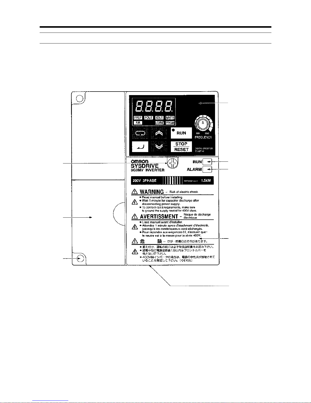
1-2 Nomenclature
H Panel
Front panel
mounting
screw
Digital Operator
ALARM display
RUN indicator
Front cover
Bottom cover
Terminal
cover
Four
mounting
holes
Note None of the following 200-V models have a terminal cover or mounting holes.
Instead,thefrontcover is used asaterminalcoverandtwo U-shaped cutouts are
provided in place of the mounting holes.
3G3MV-A2001 (0.1 kW), 3G3MV-A2002 (0.2 kW), 3G3MV-A2004(0.4 kW), and
3G3MV-A2007 (0.75 kW)
3G3MV-AB001 (0.1 kW), 3G3MV-AB002(0.2 kW),and 3G3MV-AB004(0.4 kW)
Overview Chapter 1
Page 20
1-6
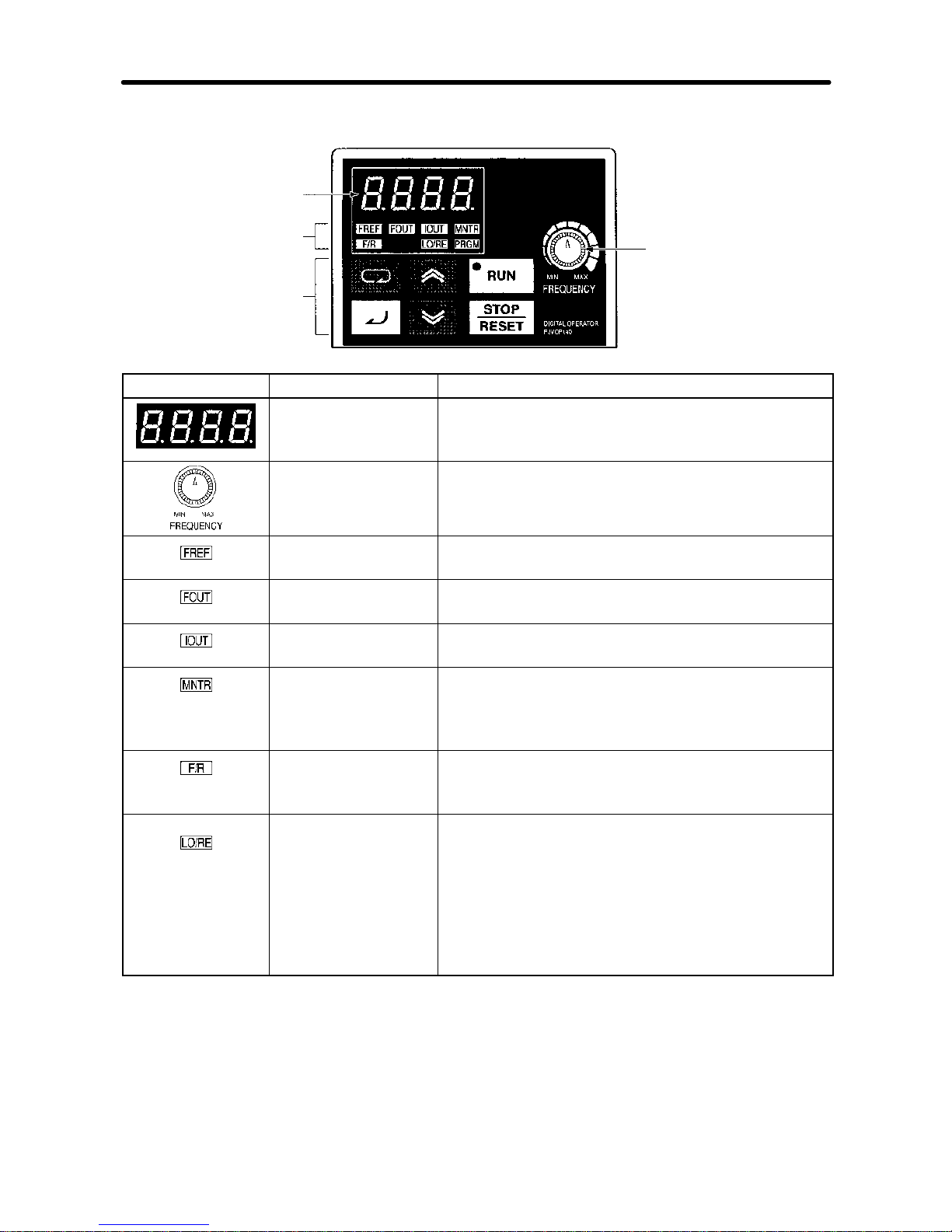
H Digital Operator
Data display
FREQUENCY
adjuster
Simplified-LED
indicators
Operation keys
Appearanc
e
Name Function
Data display Displays relevant data items, such as frequency
reference, output frequency, and parameter set
values.
FREQUENCY
adjuster
Sets the frequency reference within a range
between 0 Hz and the maximum output
frequency.
FREF indicator The frequency reference can be monitored or set
while this indicator is lit.
FOUT indicator The output frequency of the Inverter can be
monitored while this indicator is lit.
IOUT indicator The output current of the Inverter can be
monitored while this indicator is lit.
MNTR indicator The values set in U01 through U18 are
monitored while this indicator is lit. Depending on
the inverter capacity, the quantity of the Uxx will
be different.
F/R indicator The direction of rotation can be selected while
this indicator is lit when operating the Inverter
with the RUN Key.
LO/RE indicator The operation of the Inverter through the Digital
Operator or according to the set parameters is
selectable while this indicator is lit.
Note This status of this indicator can be only
monitored while the Inverter is in operation.
Any RUN command input is ignored while
this indicator is lit.
Overview Chapter 1
Page 21
1-7
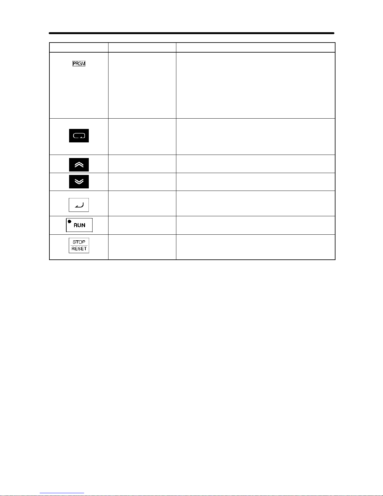
Appearance FunctionName
PRGM indicator The parameters in n001 through n179 can be set
or monitored while this indicator is lit.
Note While the Inverter is in operation, the
parameterscanbeonly monitored and only
some parameters can be changed. Any
RUN command input is ignored while this
indicator is lit. Unless n001 is 5.
Mode Key Switches the simplified-LED (setting and
monitor) item indicators in sequence.
Parameter being set will be canceled if this key is
pressed before entering the setting.
Increment Key Increases multi-function monitor numbers,
parameter numbers, and parameter set values.
Decrement Key Decreases multi-function monitor numbers,
parameter numbers, and parameter set values.
Enter Key Enters multi-function monitor numbers,
parameter numbers, and internal data values
after they are set or changed.
RUN Key Starts the Inverter running when the 3G3MV is in
operation with the Digital Operator.
STOP/RESET Key Stops the Inverter unless parameter n007 is set
to disable the STOP Key. Functions as a Reset
Key when an inverter error occurs (see note).
Note Forsafety reasons,the resetwill notwork whilea RUNcommand (forwardor reverse)isineffect.
Wait until the RUN command is OFF before resetting the Inverter.
Overview Chapter 1
Page 22

1-8
1-3 New Features
New features have been added to 3G3MV-Series models with 5.5-kW and 7.5-kW capacities (i.e., the 3G3MV-A2055/A2075/ A4055/A4075). These features are outlined
below and explained in detail in Chapter 6.
H New Features for 3G3MV-A2055/A2075/ A4055/A4075 only
D Enclosure Rating: Closed Wall-mounting Conforming to IP20/NEMA1
The 5.5-kW and 7.5-kW Inverters have closed wall-mounting specifications that conform to
IP20/NEMA1, so they can operate in an ambient temperature range of --10 to 40°C.
Note Tooperate thisInverterwithin anambienttemperature range of --10to50°C, removethetop and
bottom covers to convert it to a panel-mounting model (IP00).
D Default Settings Changed for V/f Patterns (Parameters: n011 to n017)
For 5.5-kW and 7.5-kW Inverters, two of the default settings have been changed. The default settings
forthemiddle output frequencyvoltage(VC) (n015)andthe minimum outputfrequency voltage (VMIN
(n017) have both been changed to 10 V for 200-V-class models and to 20 V for 400-V-class models.
D Inverter Overheating Warning Input
(Parameters: n050 to n056; Fault Display: oH3)
AnInverter overheating warninginputhas beenaddedas a newfunction that canbe set formulti-function inputs1to 7 (n050 to n056). When thiswarningis input, an oH3 fault (nonfatal error, please check
page 8-11)willbe displayed. This input canbeused for functions such asthermal contact connections
for peripheral overheating detection.
D Frequency Reference Loss Detection (Parameter: n064)
Whenthefrequencyisreferencedusinganalogfrequency referenceinputs(0to 10V/4to20mA/0 to20
mA), this function detects sudden changes in analog inputs as errors (disconnection, short circuit,
breakdown,etc.)and outputs thefrequencyreference loss outputthatis set inmulti-functionoutputs 1
to3(n057ton059).After thechangeisdetected,operationcontinues at80%ofthefrequency reference
prior to the change.
D Accumulated Operating Time (Monitor: U-13; Parameters: n087, n088)
Thisfunction calculatesand storesin memorythe Inverter’saccumulated power-ONtime orRUN time.
Use it for checking and determining the maintenance schedule.
D Speed Search Adjustment (Parameters: n101, n102)
Afunctionhasbeenadded foradjustingthe speedsearch.(The speedsearchis afunctionfor detecting
and smoothly controlling the speed of a free running motor.) The speed search operating time and
search level can be adjusted.
D Input Open-phase Detection
(Parameters: n166, n167; Fault Display: PF)
Thisfunction detectsthe Inverter’sinput powersupply openphase. Openphases aredetected through
main circuit voltage fluctuations, so this function can alsobeusedfor detecting abnormal voltage fluctuations in the input power supply voltage.
Overview Chapter 1
Page 23

1-9
D Output Open-phase Detection
(Parameters: n168, n169; Fault Display: LF)
This function detects open phases between the Inverter output and the motor.
D Ground Fault Detection (Fault Display: GF)
This function detects ground faults between the Inverter output and the motor.
D Load Short-circuit Detection (Fault Display: SC)
Prior to an Inverter output, thisfunctiondetectswhether the output is short-circuited. If short-circuiting
occurs during an output, it detects an overcurrent (oC).
Overview Chapter 1
Page 24

Chapter 2
Design
2-1 Installation
2-2 Wiring
2
Page 25
2-2
2-1 Installation
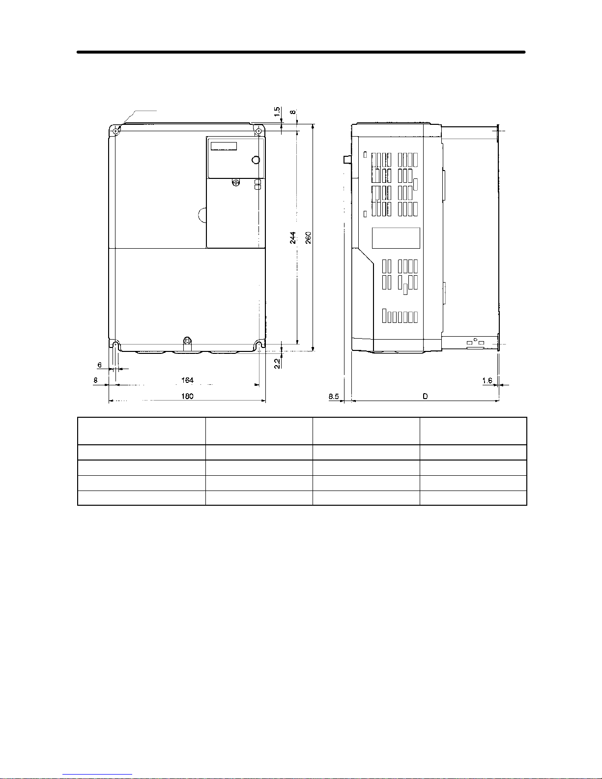
2-1-1 Dimensions
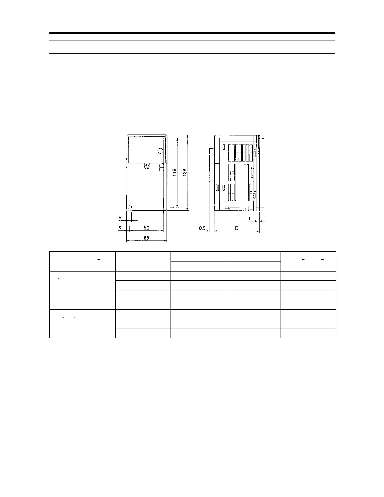
D 3G3MV-A2001 to 3G3MV-A2007 (0.1 to 0.75 kW) 3-phase 200-VAC Input
3G3MV-AB001 to 3G3MV-AB004 (0.1 to 0.4 kW) Single-phase 200-VAC
Input
Rated voltage Model 3G3MV-
Dimensions (mm)
Weight (kg)
RatedvoltageModel3G3MV-
D t
Weight(kg
)
3-phase 200 VAC
A2001 76 3 Approx. 0.6
3-phase200VAC
A2002 76 3 Approx. 0.6
A2004 108 5 Approx. 0.9
A2007 128 5 Approx. 1.1
Single-phase
AB001 76 3 Approx. 0.6
Single-phas
e
200 VAC
AB002 76 3 Approx. 0.7
AB004 131 5 Approx. 1.0
Design Chapter 2
Page 26
2-3
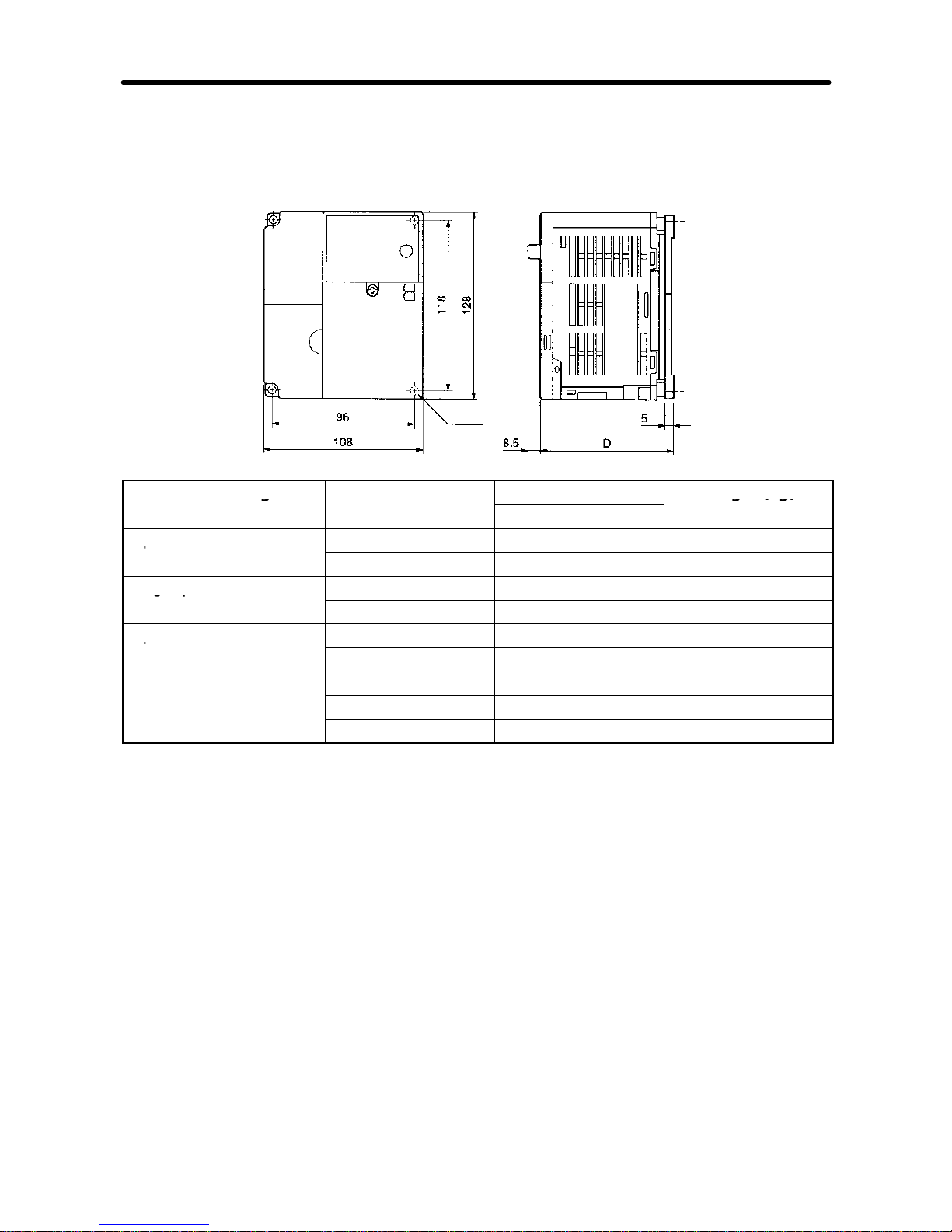
D 3G3MV-A2015 to 3G3MV-A2022 (1.5 to 2.2 kW) 3-phase 200-VAC Input
3G3MV-AB007 to 3G3MV-AB015 (0.75 to 1.5 kW) Single-phase 200-VAC
Input
3G3MV-A4002 to 3G3MV-A4022 (0.2 to 2.2 kW) 3-phase 400-VAC Input
Four, 5 dia.
Rated voltage Model 3G3MV-
Dimensions (mm)
Weight (kg)
RatedvoltageModel3G3MV-DWeight(kg
)
3-phase 200 VAC
A2015 131 Approx. 1.4
3-phase200VAC
A2022 140 Approx. 1.5
Single-phase 200 VAC
AB007 140 Approx. 1.5
Single-phase200VA
C
AB015 156 Approx. 1.5
3-phase 400 VAC
A4002 92 Approx. 1.0
3-phase400VAC
A4004 110 Approx. 1.1
A4007 140 Approx. 1.5
A4015 156 Approx. 1.5
A4022 156 Approx. 1.5
Design Chapter 2
Page 27
2-4
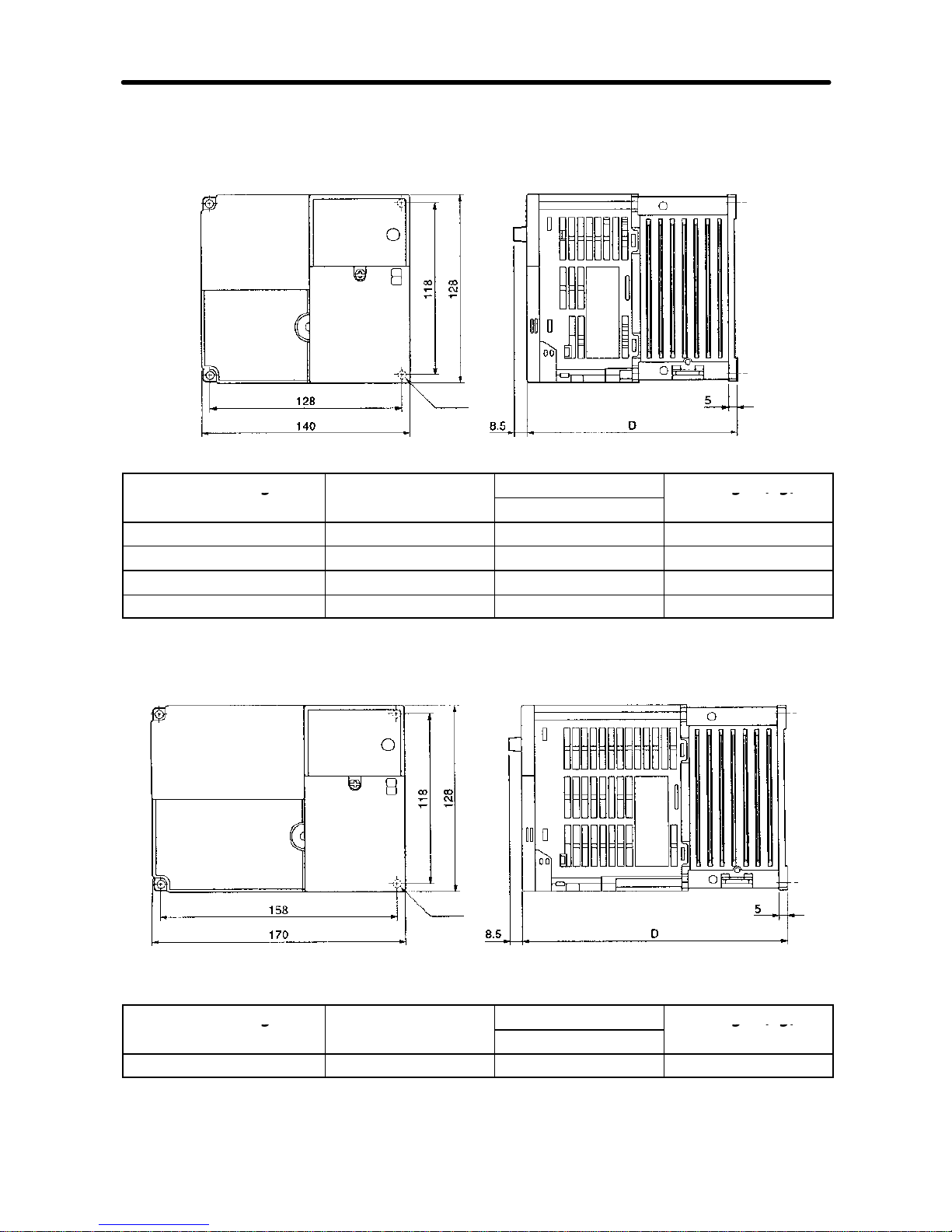
D 3G3MV-A2040 (4.0 kW) 3-phase 200-VAC Input
3G3MV-AB022 (2.2 kW) Single-phase 200-VAC Input
3G3MV--A4030 to 3G3MV-A4040 (3.0 to 4.0 kW) 3-phase 400-VAC Input
Four, 5 dia.
Rated voltage Model 3G3MV-
Dimensions (mm)
Weight (kg)
RatedvoltageModel3G3MV-DWeight(kg
)
3-phase 200 VAC A2040 143 Approx. 2.1
Single-phase 200 VAC AB022 163 Approx. 2.2
3-phase 400 VAC A4030 143 Approx. 2.1
3-phase 400 VAC A4040 143 Approx. 2.1
D 3G3MV-AB040 (4.0 kW) Single-phase 200-VAC Input
Rated voltage Model 3G3MV-
Dimensions (mm)
Weight (kg)
RatedvoltageModel3G3MV-DWeight(kg
)
Single-phase 200 VAC AB040 180 Approx. 2.9
Design Chapter 2
Page 28
2-5
D 3G3MV-A2055 to 3G3MV--A2075 (5.5 to 7.5kW) 3-phase 200-VAC Input
3G3MV-A4055 to 3G3MV--A4075 (5.5 to 7.5kW) 3-phase 400-VAC Input
Two, 6 dia.
Rated voltage Model 3G3MV- Dimensions D
(mm)
Weight (kg)
3-phase 200 VAC A2055 170 Approx. 4.6
3-phase 200 VAC A2075 170 Approx. 4.8
3--phase 400 VAC A4055 170 Approx. 4.8
3--phase 400 VAC A4075 170 Approx. 4.8
Design Chapter 2
Page 29

!
!
!
!
!
2-6
2-1-2 Installation Conditions
W ARNING Providean appropriatestoppingdeviceonthemachineside tosecuresafety.
(A holding brake is not a stopping device for securing safety.) Not doing so
may result in injury.
W ARNING Providean externalemergencystoppingdevicethatallowsaninstantaneous
stop of operation and power interruption. Not doing so may result in injury.
Caution Be sure to install the product in the correct direction and provide specified
clearancesbetweentheInverter and control panel orwithotherdevices.Not
doing so may result in fire or malfunction. See explanation below.
Caution Donotallowforeignobjectstoenterinsidetheproduct.Doingsomayresultin
fire or malfunction.
Caution Donotapplyanystrongimpact.Doingsomayresultin damagetotheproduct
or malfunction.
H Installation Direction and Dimensions
·Install the Inverter under the following conditions.
Ambient operating temperature:
Panel-mounting models (conforming to IP20): --10 to 50°C (0.1- to 4.0-kW Inverters)
Closed wall-mounting models (conforming to NEMA1 and IP20):
--10 to 40°C (5.5- to 7.5-kW Inverters)
Humidity: 95% max. (with no condensation)
Note 1. By removing the top and bottom covers froma 5.5- to 7.5-kW Inverter,it can be used
as a panel-mounting model (conforming to IP00) within an ambient temperature
range of --10 to 50°C.
· Install the Inverter in a clean location free from oil mist and dust. Alternatively, install it in a
totally enclosed panel that is completely protected from floating dust.
· Wheninstalling or operating the Inverter ,always take special care so that metal powder,oil,
water , or other foreign matter does not get into the Inverter.
· Do not install the Inverter on inflammable material such as wood.
· Ifa5.5kWor7.5kW Inverter istobeinstalled insideofacontrolpanel,itmusthavethetopand
bottom covers removed and be used as a panel-mounting model (conforming to IP00).
Design Chapter 2
Page 30
2-7
H Direction
·Install the Inverter on a vertical surface so that the characters on the nameplate are
oriented upward.
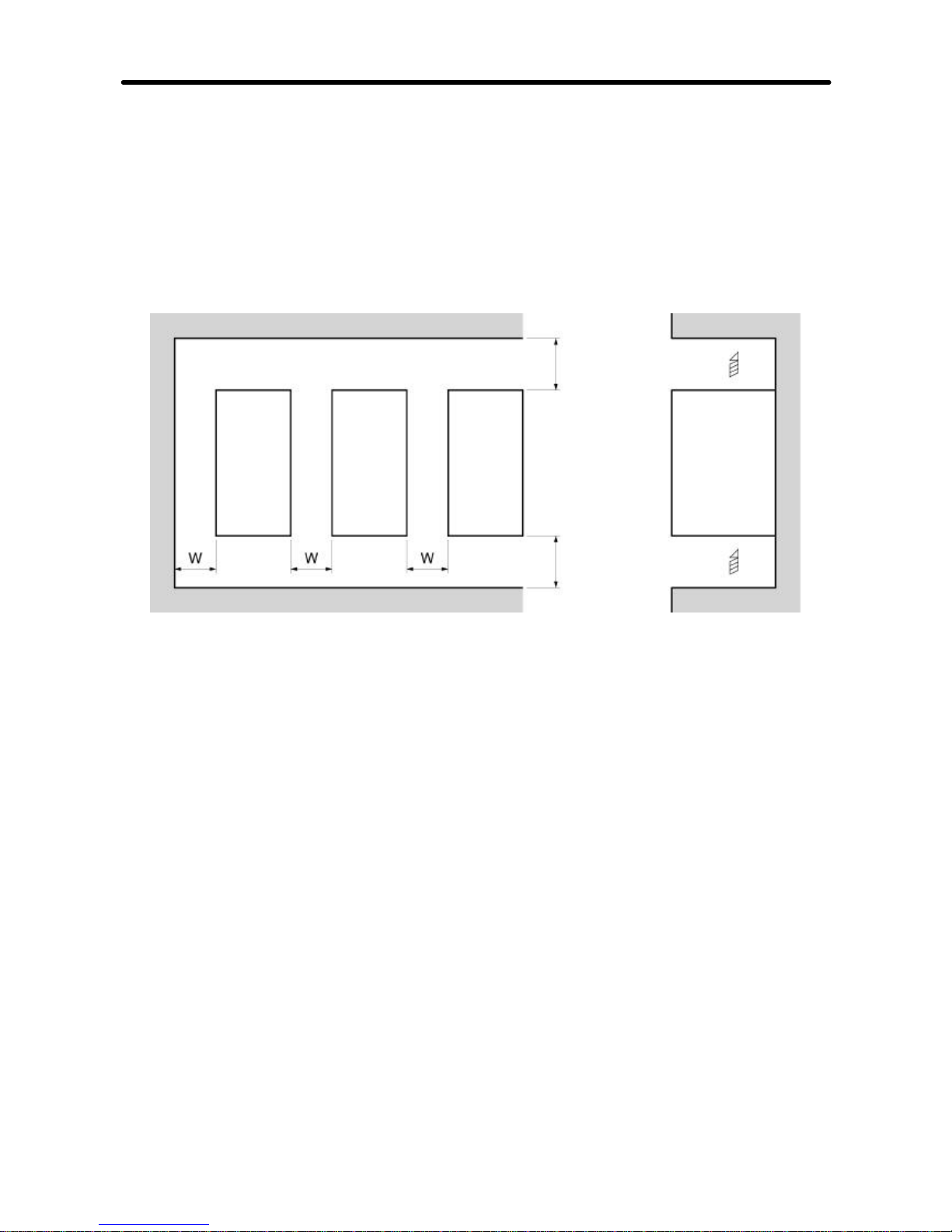
H Dimensions
·When installing the Inverter, always provide the following clearances to allow normal
heat dissipation from the Inverter.
W = 30 mm min.
Inverter
100 mm min. Air
SideInverter Inverter
100 mm min. Air
H Ambient Temperature Control
·Toenhance operation reliability,theInvertershouldbe installed inanenvironmentfree
from extreme temperature changes.
·If the Inverter is installed in an enclosed environment such as a box, use a cooling fan
or air conditioner to maintain the internal air temperature below 50°C.
Thelifeofthebuilt-inelectrolyticcapacitorsoftheInverterisprolonged by maintaining
the internal air temperature as low as possible.
·The surface temperature of the Inverter may rise approximately 30°C higher than the
ambient temperature. Be sure tokeep away equipment andwires from the Inverter as
far as possible if the equipment and wires are easily influenced by heat.
H Protecting Inverter from Foreign Matter during Installation
·Place a cover over the Inverter during installation to shield it from metal power produced by drilling.
Uponcompletion ofinstallation,alwaysremovethecoverfromtheInverter.Otherwise,
ventilation will be affected, causing the Inverter to overheat.
Design Chapter 2
Page 31

2-8
2-1-3 Removing and Mounting the Covers
To mount the Inverter, it is necessary to remove the front cover, terminal
cover (unless the Inverter is a 200-V model), and the Digital Operator. To
wire the Inverter,it is necessary to remove the front cover, terminal cover
(unlesstheInverterisa200-Vmodel),andbottomcoverfromthe Inverter.
Follow the instructions below to remove the covers from the Inverter.
To mount the covers, take the opposite steps.
H Removing the Front Cover
·Loosen the front cover mounting screws with a screwdriver.
·Press the left and right sidesof the front coverin the arrow 1 directionsand lift the bot-
tom of the cover in the arrow 2 direction to remove the front cover as shown in the following illustration.
Design Chapter 2
Page 32

2-9
H Removing the Terminal Cover
D 0.2- to 3.7-kW Inverters
· Afterthe front cover is removed, press the left and right sides of the terminal cover in
thearrow1 directionsandliftthe terminal coverinthearrow 2 directionasshowninthe
following illustration.
D 5.5-/7.5-kW Inverters
· Loosen the terminal cover screws in the direction of arrows 1.
· Presstheleft andrightsidesoftheterminalcoverinthedirectionofarrows2andlift itin
the direction of arrow 3 as shown in the following illustration.
Note None of the following 200-V models have a terminal cover. Instead, the front
cover is used as a terminal cover.
3G3MV-A2001 (0.1 kW), 3G3MV-A2002 (0.2 kW), 3G3MV-A2004 (0.4 kW),
3G3MV-A2007 (0.75 kW), 3G3MV-AB001 (0.1 kW), 3G3MV-AB002 (0.2 kW),
and 3G3MV-AB004 (0.4 kW)
Design Chapter 2
Page 33

2-10
H Removing the Bottom Cover
·Afterremovingthefrontcoverandterminalcover,pressthebottomcoverinthearrow1
direction based on position A as a fulcrum.
A
A
H Removing the Digital Operator
·Afterremovingthefront cover,liftuptheupper andlowerright-handsides(positionsA)
of the Digital Operator in the arrow 1 direction as shown in the following illustration.
A
A
Design Chapter 2
Page 34

!
!
!
!
!
!
!
!
!
!
2-11
2-2 Wiring
W ARNING Wiring must be performed only after confirming that the power
supply has been turned OFF. Not doing so may result in electrical
shock.
W ARNING Wiring must be performed by authorized personnel. Not doing so
may result in electrical shock or fire.
W ARNING Be sure to confirm operation only after wiring the emergency stop
circuit. Not doing so may result in injury.
W ARNING Alwaysconnectthe groundterminalstoaground of100W orless for
the 200-VAC class, or 10 W or less for the 400-VAC class. Not
connecting to a proper ground may result in electrical shock.
Caution Install external breakers and take other safety measures against
short-circuiting in external wiring. Not doing so may result in fire.
Caution Confirmthatthe ratedinputvoltageofthe Inverteristhesameas the
AC power supply voltage. An incorrect power supply may result in
fire, injury, or malfunction.
Caution If you use a Braking Resistor or a Braking Resistor Unit, connect
them as specified in the manual. Not doing so may result in fire.
Caution Be sure to wire correctly and securely. Not doing so may result in
injury or damage to the product.
Caution Be sure to firmly tighten the screws on the terminal block. Not doing
so may result in fire, injury, or damage to the product.
Caution Do not connect an AC power to the U, V, or W output. Doing so may
result in damage to the product or malfunction.
Design Chapter 2
Page 35

2-12
2-2-1 Terminal Block
To wire the terminal block of the Inverter, remove the front cover, terminal
cover (unless the Inverter is a 200-V model), and bottom cover from the
Inverter.
There is a label under the front cover indicating the arrangement of main
circuitterminals.Be suretoremovethe labelafterwiringthe terminals.The
output terminal of the motor has a label as well. Remove the label before
wiring the motor terminal.
H Arrangement of Control Circuit Terminals
Control circuit terminals
H Arrangement of Main Circuit Terminals
D 3G3MV-A2001 through 3G3MV-A2007 (0.1 through 0.75 kW):
3-phase 200-VAC Input
3G3MV-AB001 through 3G3MV-AB004 (0.1 through 0.4 kW):
Single-phase 200-VAC Input
Power supply input Motor output
Braking resistor
Note For single-phase input, connect R/L1 and S/L2.
Design Chapter 2
Page 36

2-13
D 3G3MV-A2015 to 3G3MV-A2022 (1.5 to 2.2 kW): 3-phase 200-VAC Input
3G3MV-AB007 to 3G3MV-AB015 (0.75 to 1.5 kW):
Single-phase 200-VAC Input
3G3MV-A4002 to 3G3MV-A4022 (0.2 to 2.2 kW): 3-phase 400-VAC Input
Power supply input
Motor output
Braking
Resistor
Note For single-phase input, connect R/L1 and S/L2.
D 3G3MV-A2040 (4.0 kW) to --A2075 (4.0 to 7.5kW): 3-phase 200-VAC Input
3G3MV-AB022 to 3G3MV-AB040 (2.2 to 4.0 kW):
Single-phase 200-VAC Input
3G3MV--A4030 to 3G3MV-A4075 (3.0 to 7.5 kW): 3-phase 400-VAC Input
Power supply input
Motor output
Braking
Resistor
Note For single-phase input, connect R/L1 and S/L2.
Design Chapter 2
Page 37

2-14
H Main Circuit Terminals
Symbol Name Description
R/L1
Power supply input
3G3MV-A2j: 3-phase 200 to 230 VAC
S/L2
terminals3G3MV-ABj:Single-phase200to240VAC(seenot
e
1
)
T/L3
1
)
3G3MV-A4j: 3-phase 380 to 460 VAC
U/T1
Motor output
terminals
3-phase power supply output for driving motors. (see
note2
)
V/T2
terminalsnote2)
3G3MV-A2j and 3G3MV-ABj: 3-phase 200 to
W/T3
230VA
C
3G3MV-A4j: 3-phase 380 to 460 VAC
B1
Braking Resistor
Terminals for attaching an external Braking Resistor or
B2
connectionterminalsaBrakingResistorUnit.(Connecttodetectovervoltage
during braking.)
+1
Connection terminals
+1 and +2:
Connect the DC reactor for suppressing harmonics to
terminals +1 and +2.
+2
DCreactor
connection terminals
When driving the Inverter with DC power, input the DC
power to terminals +1 and --.
--
+1and--
:
DC power supply
input terminals
(Terminal+1isapositiveterminal.
)
Ground terminal Be sure to ground the terminal under the following
conditions.
3G3MV-A2j: Ground at a resistance of 100 W or less.
3G3MV-ABj: Ground at a resistance of 100 W or less.
3G3MV-A4j: Ground at a resistance of 10 W or less.
To conform to EC Directives, connect to the neutral
point of the power supply.
Note Be sure to connect the ground terminal directly
to the motor frame ground.
Note 1. Connect single-phase input to both the R/L1 terminal and the S/L2 terminal.
Note 2. The maximum voltage at theoutput side corresponds to the power supplyvolt-
age for Inverter input.
Design Chapter 2
Page 38

2-15
H Control Circuit Terminals
Symbol Name Specification
Input
S1 Multi-function input 1
(Forward/Stop)
Photocoupler
8 mA at 24 V DC (See notes 2 and 3.)
S2 Multi-function input 2
(Reverse/Stop)
8mAat24VDC(Seenotes2and3.
)
S3 Multi-function input 3
(External fault: Normally open)
S4 Multi-function input 4
(Fault reset)
S5 Multi-function input 5
(Multi-step speed reference 1)
S6 Multi-function input 6
(Multi-step speed reference 2)
S7
Multi-function input 7
(Inching frequency
command)
SC Sequence input com-
mon
FS Frequency reference
power supply output
20 mA at 12 V DC
FR Frequency reference
input
0 to 10 V DC (Input impedance: 20 kW)
FC Frequency reference
common
RP Pulse train input Response frequency: 0 to 33 kHz (30% to 70% ED)*
H: 3.5 to 13.2 V
L: 0.8 V max.
(Input impedance: 2.24 kW)
CN2
1 Multi-function analog
voltage input
Voltage input (between terminals 1 and 3):
0 to 10 V DC (Input impedance: 20 kW)
2 Multi-function analog
current input
0to10VDC(Inputimpedance:20kW)
Current input (between terminals 2 and 3):
4 to 20 mA (Input impedance: 250 W). This connector
3 Multi-function analog
input common
4to20mA(Inputimpedance:25
0W).Thisconnector
is located in the Unit Operator of the Inverter.
* ED = Operating Duty Cycle.
Design Chapter 2
Page 39

2-16
Symbol Name Specification
Output
MA Multi-function contact
output (Normally open:
During operation)
Relay output
1 A max. at 30 V DC
1 A max. at 250 V AC
MB Multi-function contact
output (Normally
closed:
During operation)
1Amax.at250VA
C
MC Multi-function contact
output common
P1 Multi-function photo-
coupler output 1
(Fault)
Open collector output 50 mA max.
at 48 V DC
P2 Multi-function photo-
coupler output 2
(Fault)
PC Multi-function photo-
coupler output common
AM Multi-function analog
output
· Analog output: 2 mA max. at 0 to 10 V DC
· Pulse train output (max. output voltage: 12 V DC)
(See note 4.)
When Used as Voltage Output
Load impedance
1.5 kW min.
10 kW min.
Output voltage (insulationtype)
+5 V
+10 V
Load
impedance
External
AC Multi-function analog
output common
When External Power Supply is Used
Note Do not use a 5-V DC or 24-V DC external power
supply.Doingsocancauseinternalcircuitdamage or malfunctioning.
Input current (mA)
from external power
supply
16 mA max.
External power supply (V)
12 V DC (±5%)
Externa
l
power
supply
12 V DC
Load
impedance
Input current
16 mA
max.
External power
supply ground
Com-
R+
Receiver side Conforming to RS-422/485
Com
-
mu-
R--
ReceiversideConformingtoRS-422/485nica
-
S+
Sender side
tion
s
S--
Sendersid
e
Design Chapter 2
Page 40

2-17
Note 1. Parametersettingscanbeused to select various functions for multi-function inputs 1
to 7, multi-function contact outputs, and multi-function photocoupler outputs. The
functions in parentheses are the default settings.
Note 2. NPN is the default setting for these terminals. Wire them by providing a common
ground. No external power supply is required.
Note 3. To provide an external power supply and wire the terminals through a common posi-
tive line, set SW1 to PNP and use a 24 V DC ±10% external power supply.
Note 4. When multi-function analog outputs are used for pulse train outputs, they can be di-
rectly connected to the pulse train inputs at other 3G3MV-seriesInverters for simple
synchronization or other applications.
H Selecting Input Method
·Switches SW1 and SW2,bothofwhichare located above the control circuit terminals,
are used for input method selection.
Remove the front cover and optional cover to use these switches.
Selectors
Control circuit
terminal block
Design Chapter 2
Page 41

2-18
D Selecting Sequence Input Method
·By using SW1, NPN or PNP input can be selected as shown below.
24 VDC
S1 to 7
S1 to 7
(Default setting)
SW1
SW1
(+/--10%)
D Selecting RS-422/485 T ermination Resistance
·Terminationresistance can be selectedby setting pin 1 of the SW2 toON. The default
setting for the pin is OFF.
Selects RS-422/485 termination resistance
Selects frequency reference input method
Design Chapter 2
Page 42

2-19
Communications method Pin 1 setting
RS-422 Set to ON
RS-485 Set to ON only if the Unit is the end Slave.
120-W termination resistance (1/2 W)
Pin 1
D Selecting Frequency Reference Input Method
·By using pin 2 of SW2, voltage input or current input can be selected as the input
method for frequency reference. The default setting is for voltage input.
Parametersettingsarerequiredtogetherwiththeselectionofthe frequency reference
input method.
Frequency reference input
method
Pin 2 setting Frequency reference
selection (parameter n004)
Voltage input (default
setting)
V (OFF) Set value 2
Current input I (ON) Set value 3 or 4
Note Do not set pin 2 to ON for current input while voltage input is ON, otherwise the
resistor in the input circuit may burn out.
Design Chapter 2
Page 43

2-20
2-2-2 Standard Connections
DC reactor
(optional)
Noise Filter
3-phase 200/400 VAC
Single-phase 200 VAC (see note)
Multi-function input 1
Sequence input common
Frequency reference power
supply 20 mA at +12 V
FREQUENCY
adjuster (2kW
1/4 W min.)
Frequency reference input
Frequency reference common
Multi-function contact output
NO
NC
Common
Multi-function analog
output/Pulse monitor
output
Multi-function analog output
common
Braking Resistor
(optional)
Multi-function input 2
Multi-function input 3
Multi-function input 4
Multi-function input 5
Multi-function input 6
Multi-function input 7
Pulse
generator
Pulse train input
RS-422
communications
(RS-485 selection)
Multi-function analog voltage input (0--10V)
Multi-function analog current input (4--20mA)
Analog input common
Connector
Digital Operator
Multi-function
photocoupler output 1
Multi-function
photocoupler output 2
Multi-function
photocoupler output
common
3G3MV--PCN--CN2 cable can be used for
multi--function analog input
(rear side)
Note Connect single-phase 200 VACto terminals R/L1 and S/L2 of the 3G3MV-ABj.
Design Chapter 2
Page 44

2-21
D Example of 3-wire Sequence Connections
Stop
switch
(NC)
RUN
switch
(NO)
Direction switch
RUN input (Operates with the RUN switch closed)
Stop input (Stops with the stop switch opened)
Sequence input common
Sequence input common
Note Set parameter 052 to forward/reverse rotation command 0 for 3-wire sequence
input.
2-2-3 Wiring around the Main Circuit
H Wire Size, Terminal Screw, Screw Tightening Torque, and
Molded-case Circuit Breaker Capacities
·For the main circuit and ground, always use 600-V polyvinyl chloride
(PVC) cables.
·If any cable is long and may cause voltage drops, increase the wire size according to
the cable length.
D 3-phase 200-VAC Model
Model
3G3MV-
Terminal symbol Termi-
nal
screw
Screw
tighten-
ing
torque
(NSm)
Wire
size
(mm2)
Recom-
mended
wire
size
(mm2)
Molded-
case
circuit
breaker
capac-
ity (A)
A2001
R/L1, S/L2, T/L3, B1, B2,
--, +1, +2, U/T1, V/T2,
W/T3
M3.5 0.8 to 1.0 0.75 to 2 2 5
A2002
R/L1, S/L2, T/L3, B1, B2,
--, +1, +2, U/T1, V/T2,
W/T3
M3.5 0.8 to 1.0 0.75 to 2 2 5
A2004
R/L1, S/L2, T/L3, B1, B2,
--, +1, +2, U/T1, V/T2,
W/T3
M3.5 0.8 to 1.0 0.75 to 2 2 5
Design Chapter 2
Page 45

2-22
Model
3G3MV-
Molded-
case
circuit
breaker
capac-
ity (A)
Recom-
mended
wire
size
(mm2)
Wire
size
(mm2)
Screw
tighten-
ing
torque
(NSm)
Termi-
nal
screw
Terminal symbol
A2007
R/L1, S/L2, T/L3, B1, B2,
--, +1, +2, U/T1, V/T2,
W/T3
M3.5 0.8 to 1.0 0.75 to 2 2 10
A2015
R/L1, S/L2, T/L3, B1, B2,
--, +1, +2, U/T1, V/T2,
W/T3
M4 1.2 to 1.5 2 to 5.5
2
20
3.5
A2022
R/L1, S/L2, T/L3, B1, B2,
--, +1, +2, U/T1, V/T2,
W/T3
M4 1.2 to 1.5 2 to 5.5 3.5 20
A2040
R/L1, S/L2, T/L3, B1, B2,
--, +1, +2, U/T1, V/T2,
W/T3
M4 1.2 to 1.5 2 to 5.5 5.5 30
A2055
R/L1, S/L2, T/L3, B1, B2,
--, +1, +2, U/T1, V/T2,
W/T3
M5 2.5 5.5 to 8 8 50
A2075
R/L1, S/L2, T/L3, B1, B2,
--, +1, +2, U/T1, V/T2,
W/T3
M5 2.5 5.5 to 8 8 60
D Single-phase 200-VAC Model
Model
3G3MV-
Terminal symbol Termi-
nal
screw
Terminal
torque
(NSm)
Wire
size
(mm2)
Recom-
mended
wire
size
(mm2)
Circuit
breaker
capac-
ity (A)
AB001
R/L1, S/L2, T/L3, B1, B2,
--, +1, +2, U/T1, V/T2,
W/T3
M3.5 0.8 to 1.0 0.75 to 2 2 5
Design Chapter 2
Page 46

2-23
Model
3G3MV-
Circuit
breaker
capac-
ity (A)
Recom-
mended
wire
size
(mm2)
Wire
size
(mm2)
Terminal
torque
(NSm)
Termi-
nal
screw
Terminal symbol
AB002
R/L1, S/L2, T/L3, B1, B2,
--, +1, +2, U/T1, V/T2,
W/T3
M3.5 0.8 to 1.0 0.75 to 2 2 5
AB004
R/L1, S/L2, T/L3, B1, B2,
--, +1, +2, U/T1, V/T2,
W/T3
M3.5 0.8 to 1.0 0.75 to 2 2 10
AB007
R/L1, S/L2, T/L3, B1, B2,
--, +1, +2, U/T1, V/T2,
W/T3
M4 1.2 to 1.5 2 to 5.5
3.5
20
2
AB015
R/L1, S/L2, T/L3, B1, B2,
--, +1, +2, U/T1, V/T2,
W/T3
M4 1.2 to 1.5 2 to 5.5
5.5
20
3.5
AB022
R/L1, S/L2, T/L3, B1, B2,
--, +1, +2, U/T1, V/T2,
W/T3
M4 1.2 to 1.5 2 to 5.5 5.5 40
AB040
R/L1, S/L2, T/L3, B1, B2,
--, +1, +2, U/T1, V/T2,
W/T3
M5 2.3 to 2.4 5.5 to 8 8
50
M4 1.2 to 1.5 2 to 8 5.5
D 3-phase 400-VAC Model
Model
3G3MV-
Terminal symbol Termi-
nal
screw
Screw
tighten-
ing
torque
(NSm)
Wire
size
(mm2)
Recom-
mended
wire
size
(mm2)
Molded-
case
circuit
breaker
capac-
ity (A)
A4002
R/L1, S/L2, T/L3, B1, B2,
--, +1, +2, U/T1, V/T2,
W/T3
M4 1.2 to 1.5 2 to 5.5 2 5
Design Chapter 2
Page 47

2-24
Model
3G3MV-
Molded-
case
circuit
breaker
capac-
ity (A)
Recom-
mended
wire
size
(mm2)
Wire
size
(mm2)
Screw
tighten-
ing
torque
(NSm)
Termi-
nal
screw
Terminal symbol
A4004
R/L1, S/L2, T/L3, B1, B2,
--, +1, +2, U/T1, V/T2,
W/T3
M4 1.2 to 1.5 2 to 5.5 2 5
A4007
R/L1, S/L2, T/L3, B1, B2,
--, +1, +2, U/T1, V/T2,
W/T3
M4 1.2 to 1.5 2 to 5.5 2 5
A4015
R/L1, S/L2, T/L3, B1, B2,
--, +1, +2, U/T1, V/T2,
W/T3
M4 1.2 to 1.5 2 to 5.5 2 10
A4022
R/L1, S/L2, T/L3, B1, B2,
--, +1, +2, U/T1, V/T2,
W/T3
M4 1.2 to 1.5 2 to 5.5 2 10
A4030
R/L1, S/L2, T/L3, B1, B2,
--, +1, +2, U/T1, V/T2,
W/T3
M4 1.2 to 1.5 2 to 5.5
2
20
3.5
A4040
R/L1, S/L2, T/L3, B1, B2,
--, +1, +2, U/T1, V/T2,
W/T3
M4 1.2 to 1.5 2 to 5.5
2
20
3.5
A4055
R/L1, S/L2, T/L3, B1, B2,
--, +1, +2, U/T1, V/T2,
W/T3
M4 1.8 5.5 5.5 30
A4075
R/L1, S/L2, T/L3, B1, B2,
--, +1, +2, U/T1, V/T2,
W/T3
M5 1.8 5.5 to 8 5.5 30
Design Chapter 2
Page 48

2-25
H Wiring on the Input Side of the Main Circuit
D Installing a Molded-case Circuit Breaker
Alwaysconnect thepowerinputterminals(R/L1,S/L2,andT/L3) andpowersupplyviaa
molded case circuit breaker (MCCB) suitable to the Inverter.
·Install one wiring circuit breaker per Inverter.
·Choose an MCCB with a capacity of 1.5 to 2 times the Inverter’s rated current.
·For the MCCB’s time characteristics, be sure to consider the Inverter’s overload
protection (one minute at 150% of the rated output current).
·IftheMCCB istobeusedincommonamongmultiple Inverters,orotherdevices,setup
a sequence such thatthe power supply will be turned OFF by a fault output, asshown
in the following diagram.
3-phase/
Single-phase
200 VAC
3-phase
400 VAC
Power
supply
Inverter
Fault output
(NC)
(see
note)
Note Use a 400/200 V transformer for a 400-V model.
D Installing a Ground Fault Interrupter
Inverteroutputsuse high-speed switching, so high-frequency leakage current is generated.
Ingeneral, aleakagecurrent ofapproximately100 mAwilloccur foreachInverter(when
the power cable is 1 m) and approximately 5 mA for each additional meter of power
cable.
Therefore, at the power supply input area, use a special-purpose breaker forInverters,
which detects only the leakage current in the frequency range that is hazardous to
humans and excludes high-frequency leakage current.
Design Chapter 2
Page 49

2-26
·For the special-purpose breaker for Inverters, choose a ground fault interrupter with a
sensitivity amperage of at least 10 mA per Inverter.
·When using a generalleakagebreaker,choose a ground fault interrupter with asensitivity amperage of 200 mA or more per Inverter and with an operating time of 0.1 s or
more.
D Installing a Magnetic Contactor
If the power supplyof the main circuit is to be shut off because ofthe sequence, amagnetic contactor can be used instead of a molded-case circuit breaker.
When a magnetic contactor is installed on the primary side of the main circuit to stop a
load forcibly,however, the regenerative braking does not work and the load coasts to a
stop.
·A load can be started and stopped by opening and closing the magnetic contactor on
the primary side. Frequently opening and closing the magnetic contactor, however,
may cause the Inverter to break down.
·WhentheInverterisoperated withtheDigitalOperator,automaticoperation cannotbe
performed after recovery from a power interruption.
·WhenusingtheBrakingResistorUnit,besuretoarrangeasequence inwhichthethermal relay of the Unit turns the magnetic contactor OFF.
D Connecting Input Power Supply to the Terminal Block
Inputpowersupplycanbeconnectedto any terminal on the terminal block because the
phasesequence of input power supply isirrelevantto the phase sequence (R/L1,S/L2,
and T/L3).
D Installing an AC Reactor
If the Inverter is connected to a large-capacity power transformer (660 kW or more) or
the external phase advance capacitor of the customer is switched, an excessive peak
current may flow through the input power circuit, causing the converter unit to break
down.
To prevent this, install an optional AC reactor on the input side of the Inverter.
This also improves the power factor on the power supply side.
D Installing a Surge Absorber
Always use a surge absorber or diode for the inductive loads near the Inverter. These
inductive loads include magnetic contactors, electromagnetic relays, solenoid valves,
solenoid, and magnetic brakes.
Design Chapter 2
Page 50

2-27
D Installing a Noise Filter on the Power Supply Side
The Inverter’s outputs utilize high-speed switching, so noise may be transmitted from
the Inverter to the power line and adversely affect other devices in the vicinity. It is recommended that a Noise Filter be installed at the Power Supply to minimize this noise
transmission.Conversely, noise canalsobereducedfrom thepowerlinetothe Inverter.
Wiring Example
Power
supply
3G3MV-PFI
Noise
Filter
3G3MV
SYSDRIVE
Programmable
Controller
Other controllers
Note Use a special-purpose Noise Filter for the SYSDRIVE 3G3MV. A general pur-
pose noise filter will be less effective and may not reduce noise.
Please, use the noise filters as explained in Chapter 9-2.
H Wiring on the Output Side of the Main Circuit
D Connecting the Terminal Block to the Load
Connect output terminals U/T1, V/T2, and W/T3 to motor lead wires U, V, and W.
Check that the motor rotates forward with the forward command. Forward meansshaft
of the AC motor rotates in CCW (Counter Clock Wise), if you look from shaft to motor
end.Switch overanytwooftheoutputterminalsto eachotherandreconnectif themotor
rotates in reverse with the forward command.
D Never Connect a Power Supply to Output Terminals
Never connect a power supply to output terminals U/T1, V/T2, or W/T3.
Ifvoltageis appliedtotheoutput terminals,theinternal circuitofthe Inverterwillbedam-
aged.
D Never Short or Ground Output Terminals
Ifthe outputterminalsaretouchedwithbare handsorthe outputwirescome intocontact
withtheInvertercasing, an electric shockorgroundingwilloccur.Thisis extremely hazardous.
Also, be careful not to short the output wires.
Design Chapter 2
Page 51

2-28
D Do not Use a Phase Advancing Capacitor or Noise Filter
Never connect a phase advance capacitor or LC/RC Noise Filter to the output circuit.
Doing so will result in damage to the Inverter or cause other parts to burn.
D Do not Use an Electromagnetic Switch of Magnetic Contactor
Do not connect an electromagnetic switch of magnetic contactor to the output circuit.
If a load is connected to the Inverter during running, an inrush current will actuate the
overcurrent protective circuit in the Inverter.
D Installing a Thermal Relay
The Inverter has an electronic thermal protection function to protect the motor from
overheating. If, however, more than one motor is operated with one inverter or a multipolar motor is used, always install a thermal relay (THR) between the Inverter and the
motor and set n037 to 2 (no thermal protection).
In this case, program the sequence so that the magnetic contactor on the input side of
the main circuit is turned OFF by the contact of the thermal relay.
D Installing a Noise Filter on the Output Side
ConnectaNoiseFiltertotheoutputsideoftheInvertertoreduceradionoiseandinduction noise.
Power
supply
3G3MV
SYSDRIVE
3G3IV-PFO
Signal line
Induction noise Radio noise
Controller
AM radio
Note Please, check page 2-41 for more detailed explanation.
Induction Noise: Electromagneticinduction generates noise on the signal line, caus-
ing the controller to malfunction.
Radio Noise: Electromagnetic waves from the Inverter and cables cause the
broadcasting radio receiver to make noise.
Design Chapter 2
Page 52

2-29
D Countermeasures against Induction Noise
As described previously, a Noise Filter can be used to prevent induction noise from
being generated on the output side. Alternatively, cables can be routed through a
grounded metal pipe to prevent induction noise. Keeping the metal pipe at least 30 cm
away from the signal line considerably reduces induction noise.
Power supply
3G3MV
SYSDRIVE
Metal pipe
30 cm min.
Signal line
Controller
D Countermeasures against Radio Interference
Radio noise is generated from the Inverter as well as the input and output lines. To
reduce radio noise, install Noise Filters on both input and output sides, and also install
the Inverter in a totally enclosed steel box.
The cable between the Inverter and the motor should be as short as possible.
Power supply
Noise
Filter
Steel box
3G3MV
SYSDRIVE
Metal pipe
Noise
Filter
D Cable Length between Inverter and Motor
As the cable lengthbetween the Inverter and the motor is increased, the floating capa-city between the Inverter outputs and the ground is increased proportionally. The increase in floating capacity at the Inverter outputs causes the high-frequency leakage
current to increase, and this may adversely affect peripheral devices and the current
detectorin theInverter’soutputsection.Topreventthis fromoccurring,use acableofno
more than 100 meters between the Inverter and the motor.If the cable must be longer
than100 meters, take measures to reducethefloating capacity by notwiring in metallic
ducts, by using a separate cable for each phase, and so on.
Also adjust the carrierfrequency (set in n80) according to the cable length between the
Inverter and the motor, as shown in the table below.
Design Chapter 2
Page 53

2-30
Cable length 50 m max. 100 m max. More than 100 m
Carrier frequency 10 kHz max. 5 kHz max. 2.5 kHz max.
D Single--phase motors cannot be used
Theinverterisnotsuitedforthevariablespeedcontrolofsingle--phasemotors.Single-phase motors are either capacitor start motors or split--phase start motors (the method
fordetermining rotationdirectionatstartupisdifferent).Ifacapacitorstart motorisused,
the capacitor may be damaged by a sudden electric discharge caused by inverter output. If a split--phase motor is used, the starting coil may burn because the centrifugal
switch does not operate.
Design Chapter 2
Page 54

2-31
H Ground Wiring
·Alwaysusethe groundterminalof the200-VInverterwithagroundresistanceof100W
or less. Similarly, always use the ground terminal of the 400-V Inverter with a ground
resistance of 10 W or less.
·Do not share the ground wire with other devices such as welding machines or power
tools.
·Always use a ground wire that complies with technical standards on electrical equipment and minimize the length of the ground wire.
Leakage current flows through the Inverter. Therefore, if the distance between the
groundelectrode andtheground terminalistoo long,thepotential onthegroundterminal of the Inverter will become unstable.
·When using more than one Inverter, be careful not to loop the ground wire.
Design Chapter 2
Page 55

2-32
H Harmonics
D Definition
Harmonics consist of electric power produced from AC power and alternating at frequencies that are integral multiples of the frequency of the AC power.
The following frequencies are harmonics of a 60- or 50-Hz commercial power supply.
Second harmonic: 120 (100) Hz
Third harmonic: 180 (150) Hz
Second harmonic (120 Hz)
Basic frequency (60 Hz)
Third harmonic (180 Hz)
Problems Caused by Harmonics Generation
Thewaveformofthe commercial power supplywillbedistortedifthecommercialpower
supply contains excessive harmonics.Machines with such a commercial power supply
will malfunction or generate excessive heat.
Basic frequency (60 Hz) Third harmonic (180 Hz)
Distorted current wave
form
D Causes of Harmonics Generation
·Usually, electric machines have built-in circuitry that converts commercial AC power
supply into DC power.
Such AC power, however, contains harmonics due to the difference in current flow
between DC and AC.
Obtaining DC from AC Using Rectifiers and Capacitors
DC voltage is obtained by converting AC voltage into a pulsating one-side voltage with
rectifiers and smoothing the pulsating one-side voltage with capacitors. Such AC current, however, contains harmonics.
Design Chapter 2
Page 56

2-33
Inverter
The Inverter as well as normal electric machines has an input current containing harmonics because the Inverter converts AC into DC. The output current of the Inverter is
comparatively high. Therefore, the ratio of harmonics in the output current of the
Inverter is higher than that of any other electric machine.
Voltage
Time
Rectified
Voltage
Time
Smoothed
Voltage
Time
Current
Time
A current flows into the
capacitors. The current
is different from the
voltage in waveform.
Design Chapter 2
Page 57

2-34
D Countermeasures with Reactors against Harmonics Generation
DC/AC Reactors
TheDCreactor andACreactorsuppressharmonics and currentsthatchangesuddenly
and greatly.
TheDCreactorsuppresses harmonics better thantheACreactor.TheDCreactorused
with the AC reactor suppresses harmonics more effectively.
The input power factor of the Inverter is improved by suppressing the harmonics of the
input current of the Inverter.
Connection
Connect the DC reactor to the internal DC power supply of the Inverter after shutting
OFF the power supply to the Inverter and making sure that the charge indicator of the
Inverter turns OFF.
Do not touch the internal circuitry of the Inverter in operation, otherwise an electric
shock or burn injury may occur.
Wiring Method
Please refer to Chapter 9 for more detailed information on AC and DC Reactors.
[With DC Reactor]
3-phase 200 VAC,
single-phase
200 VAC, or
3-phase 400 VAC
Power supply
DC reactor
(optional)
SYSDRIVE
3G3MV
[With DC and AC Reactors]
3-phase 200 VAC,
single-phase
200 VAC, or
3-phase 400 VAC
Power supply
AC reactor
(optional)
DC reactor
(optional)
SYSDRIVE
3G3MV
Design Chapter 2
Page 58

2-35
Reactor Effects
Harmonics are effectively suppressed whenthe DC reactor is used with the AC reactor
as shown in the following table.
Harmonics
Harmonic generation rate (%)
Harmonics
suppression
method
5th
har-
monic
7th
har-
monic
11th
har-
monic
13th
har-
monic
17th
har-
monic
19th
har-
monic
23rd
har-
monic
25th
har-
monic
No reactor 65 41 8.5 7.7 4.3 3.1 2.6 1.8
AC reactor 38 14.5 7.4 3.4 3.2 1.9 1.7 1.3
DC reactor 30 13 8.4 5 4.7 3.2 3.0 2.2
DC and AC
reactors
28 9.1 7.2 4.1 3.2 2.4 1.6 1.4
H Connecting the Braking Resistor and Braking Resistor Unit
Whenrunning aloadwithalargeinertiaora verticalaxis,regenerationenergywill return
to the Inverter. If OV (overvoltage) is generated during deceleration, this indicates that
the regeneration energy is exceeding the capacity of the Inverter. In this case, use a
Braking Resistor or a Braking Resistor Unit.
·Connect the Braking Resistor as shown in the following diagram.
Note 1. When using a Braking Resistor, install a thermal relay to monitor the tempera-
ture of the resistor.
Note 2. When using a Braking Resistor or a Braking Resistor Unit, be sure to include a
sequence whereby the power supply for the Inverter will be turned OFF in the
case of abnormal overheating. Not doing so may result in burning.
S Braking Resistor: Use the output of the thermal relay used to monitor the tempera-
ture of the thermometer.
S Braking Resistor Unit: Use the error contact output of the Braking Resistor Unit.
Design Chapter 2
Page 59

2-36
·When using a Braking Resistor, be sure to set n092 (deceleration stall prevention
selection) to “1” (without deceleration stall prevention).
3-phase, 200 VAC (single-phase
200 VAC/3-phase 200 VAC)
Power
supply
Inverter
Braking
Resistor/Braking
Resistor Unit
Contact points for thermal trip of Braking
Resistor Unit or external thermal relay
D Braking Resistors and Braking Resistor Units for 200-V-class Inverters
Inverter
3G3MV-
Braking Resistor
(3% usage rate ED)
3G3IV-
Braking Resistor Unit
(10% usage rate ED)
3G3IV-
Minimum
connection
resistance
A2001/AB001
PERF150WJ401 (400 W) --- 300 W
A2002/AB002
PERF150WJ401(40
0W)---300
W
A2004/AB004
PERF150WJ201 (200 W) PLKEB20P7 (200 W, 70 W)
200 W
A2007/AB007
PERF150WJ201(20
0W)PLKEB20P7(20
0W,70W)
120 W
A2015/AB015 PERF150WJ101 (100 W) PLKEB21P5 (100 W, 260 W)
60 W
A2022/AB022 PERF150WJ700 (70 W) PLKEB22P2 (70 W, 260 W)
6
0
W
A2040/AB040 PERF150WJ620 (62 W) PLKEB23P7 (40 W, 390 W) 32 W
A2055 PERF500WJ360T (36 W) PLKEB25P5 (30 W, 520 W) 9.6 W
A2075 PERF101WJ360T (36 W) PLKEB27P5 (20 W, 780 W) 9.6 W
Note Donot use resistances less than thantheminimumconnectionresistancevalue.
Doing so may damage the Inverter.
Note The usage rate is shown as a percentage of the braking time in one cycle. If one
cycleis10seconds,forexample,one second of braking is possible using aBraking Resistor Unit (10% usage rate ED). If the usage rate is to be exceeded, a detailed regeneration energy calculation will be required.
Design Chapter 2
Page 60

2-37
D Braking Resistors and Braking Resistor Units for 400-V-class Inverters
Inverter
3G3MV-
Braking Resistor
(3% usage rate ED)
3G3IV-
Braking Resistor Unit
(10% usage rate ED)
3G3IV-
Minimum
connection
resistance
A4002
PERF150WJ751 (750 W) PLKEB40P7 (750 W, 70 W) 750 W
A4004
PERF150WJ751(75
0W)PLKEB40P7(75
0W,70W)75
0
W
A4007 510 W
A4015 PERF150WJ401 (400 W) PLKEB41P5 (400 W, 260 W) 240 W
A4022 PERF150WJ301 (300 W) PLKEB42P2 (250 W, 260 W) 200 W
A4030 PERF150WJ401 (400 W) ´ 2 PLKEB43P7 (150 W, 390 W) 100 W
A4040 PERF150WJ401 (400 W) ´ 2 PLKEB43P7 (150 W, 390 W) 100 W
A4055 PERF500WJ360T (36 W) PLKEB45P5 (100 W, 520 W) 32 W
A4075 PERF101WJ360T (36 W) PLKEB47P5 ( 75 W, 780 W) 32 W
Note Donot use resistances less than thantheminimumconnectionresistancevalue.
Doing so may damage the Inverter.
Note The usage rate is shown as a percentage of the braking time in one cycle. If one
cycleis10seconds,forexample,one second of braking is possible using aBraking Resistor Unit (10% usage rate ED). If the usage rate is to be exceeded, a detailed regeneration energy calculation will be required.
D The dimensions of a Braking Resistor Unit
Model No.
Dimensions (mm)
Weight
ModelNo
.
3G3IV-
A B C D Mounting Screws
Weigh
t
(kg)
PLKEB40P7 105 275 50 260 M5x3 3.0
PLKEB41P5 130 350 75 335 M5x4 4.5
PLKEB42P2 130 350 75 335 M5x4 4.5
PLKEB43P7 130 350 75 335 M5x4 5.0
PLKEB45P5 250 350 200 335 M6x4 7.5
PLKEB47P5 250 350 200 335 M6x4 8.5
Design Chapter 2
Page 61

2-38
2-2-4 Wiring Control Circuit Terminals
A control signal line must be 50 m maximum and separated from power
lines.
The frequency reference must be input into the Inverter through shielded,
twisted-pair wires.
H Wiring Control I/O Terminals
Wire each control I/O terminal under the following conditions.
D Wires and Tightening Torque
Multi-function Contact Output (MA, MB, and MC)
Terminal
screw size
Tightening
torque N S m
Wire Wire size
mm2(A WG)
Recommended
wire size
mm2(A WG)
Cable
M3 0.5 to 0.6
Single wire 0.5 to 1.25
(20 to 16)
0.75 (18) Cable with
polyethylene
Stranded
wire
0.5 to 1.25
(20 to 16)
polyethylen
e
sheath
Sequential Input (S1 through S7 and SC), Multi-function Photocoupler
Output (P1, P2, PC), RS-422/485 Communications (R+, R--, S+, S--) and
Multi-function Analog Output (AM or AC), and Pulse T rain Input (RP)
Terminal
screw size
Tightening
torque N S m
Wire Wire size
mm2(A WG)
Recommended
wire size
mm2(A WG)
Cable
M2 0.22 to 0.25
Single wire 0.5 to 1.25
(20 to 16)
0.75 (18) Cable with
polyethylene
Stranded
wire
0.5 to 0.75
(20 to 18)
polyethylen
e
sheath
Frequency Reference Input (FR, FS, and FC)
Terminal
screw size
Tighten-
ing torque
N S m
Wire Wire size
mm
2
(A WG)
Recom-
mended
wire size
mm2(A WG)
Cable
M2 0.22 to
0.25
Single wire 0.5 to 1.25
(20 to 16)
0.75 (18) Special cable with
polyethylene sheath
0.2
5
Stranded
wire
0.5 to 0.75
(20 to 18)
polyethylenesheat
h
and shield for
measurement use
Design Chapter 2
Page 62

2-39
D Solderless Terminals for Control Circuit Terminals
The use of solderless terminals for the control circuit terminals is recommended
because solderless terminals are easy to connect securely.
Note When using the following solderless terminal, make sure that the wire size is
0.5 mm2.
1.0 dia.
2.6 dia.
Model: Phoenix Contact’s A1 0.5-8 WH
(Size: mm)
D Wiring Method
1. Loosen the terminal screws with a thin-slotted screwdriver.
2. Insert the wires from underneath the terminal block
3. Tighten the terminal screws firmly to a torque of 0.5 NSm.
Note 1. Always separate the control signal line from the main circuit cables and other
power cables.
Note 2. Do not solder the wires to the control circuit terminals. The wires may not con-
tact well with the control circuit terminals if the wires are soldered.
Note 3. The endofeachwire connectedtothecontrolcircuit terminalsmustbestripped
for approximately 5.5 mm.
Control circuit
terminal block
Thin-slotted screwdriver
Strip the end for 5.5 mm
if no solderless terminal
is used.
Wires
Solderless
terminal or wire
without soldering
Note Applying a torque of greater
than 0.5 NSm may damage the
terminal block. If the tightening
torque is insufficient, however,
wires may be disconnected.
Note 4. Connect the shieldtothe groundterminal of the inverter. Do not groundthe shield
on control side.
Note 5. Cover the shield with tape so that the shield will not come into contact with other
signal wires or machines.
Design Chapter 2
Page 63

2-40
H Wiring Frequency Reference Input Terminals
Wirethefrequencyreference input terminals FRandFCasdescribedbelowforexecuting frequency references with the D/A Unit for digital-to-analog data conversion or
external power supply.
D Wires Used
Useshielded, twisted-pair wires for wiring in order topreventtheInverterfrommalfunctioning due to noise.
Wire type Wire size Wire to be used
Single wire 0.5 to 1.25 mm
2
Polyethylene-shielded cable
Stranded wire 0.5 to 0.75 mm
2
Polyethylene-shieldedcabl
e
for measurement use
D Solderless Terminals for Frequency Reference Input Terminals
The use of solderless terminals for the frequency reference input terminals is recommended because solderless terminals are easy to connect securely.
Note Makesure thatthewiresizeis0.5mm2whenusing thefollowingsolderlesstermi-
nal.
1.0 dia.
2.6 dia. (Size: mm)
Model: Phoenix Contact’s A1 0.5-8 WH
D Wiring Method
·The wiring method for the frequency reference input terminals is the same as that of
the control I/O terminals.
·Always separate the control signal line from the main circuit cables and other power
cables.
·Connect the shield to the ground terminal of the Inverter. Do not connect the shield to
the load.
·Cover the shield with tape so that the shield will not come into contact with other signal
wires or machines.
Design Chapter 2
Page 64

2-41
2-2-5 Conforming to EC Directive
The following description provides the wiring method of the Inverter to
meet EC Directive requirements. If the following requirements are not
satisfied, the whole equipment incorporating the Inverter will need further
confirmation.
H Standard Connection
D Main Circuit Terminals
Line breakers
3-phase 200 VAC, single-phase
200 VAC, or 3-phase 400 VAC
Noise Filter
Clamp core
Clamp core
Braking Resistor
(optional)
Design Chapter 2
Page 65

2-42
D Control Circuit Terminals
Multi-function input 1
FREQUENCY
adjuster (2kW
1/4 W min.)
Multi-function contact output
NO
NC
Common
Multi-function analog
output/Pulse monitor
output
Multi-function analog
output common
Multi-function input 2
Multi-function input 3
Multi-function input 4
Multi-function input 5
Multi-function input 6
Multi-function input 7
Pulse
generator
Pulse train input
Multi-function
photocoupler output 1
Multi-function
photocoupler output 2
Multi-function photocoupler
output common
RS-422
communications
(RS-485 selection)
Frequency reference power
supply 20 mA at +12 V
Frequency reference input
Frequency reference common
Sequence input common
Note I/O signals can be connected to a single shielded cable.
Design Chapter 2
Page 66

2-43
H Conforming to EC Directives
D Wiring the Power Supply
Make sure that the Inverter and Noise Filter are grounded together.
·Alwaysconnectthepower inputterminals(R/L1,S/L2,and T/L3) andpowersupplyvia
a dedicated Noise Filter.
·Reduce the length of the ground wire as much as possible.
·Locate the Noise Filter as close as possible to the Inverter. Make sure that the cable
length between the Noise Filter and the Inverter does not exceed 40 cm.
·The following Noise Filters are available (all footprint type).
3-phase 200-VAC Noise Filter
Inverter 3-phase 200-VAC Noise Filter
Model 3G3MV- Model 3G3MV- Rated current (A)
A2001/A2002/A2004/A2007 PFI2010-E 10
A2015/A2022 PFI2020-E 16 to 20
A2040 PFI2030-E 26 to 30
A2055/A2075 PFI2050--E 50
Single-phase 200-VAC Noise Filter
Inverter Single-phase 200-VAC Noise Filter
Model 3G3MV- Model 3G3MV- Rated current (A)
AB001/AB002/AB004 PFI1010-E 10
AB007/AB015 PFI1020-E 20
AB022 PFI1030-E 30
AB040 PFI1040-E 40
3-phase 400-VAC Noise Filter
Inverter 3-phase 400-VAC Noise Filter
Model 3G3MV- Model 3G3MV- Rated current (A)
A4002/A4004 PFI3005-E 5
A4007/A4015/A4022 PFI3010-E 10
A4030/A4040 PFI3020-E 15 to 20
A4055/A4075 PFI3030--E 30
Design Chapter 2
Page 67

2-44
D Connecting a Motor to the Inverter
·When connecting a motor to the Inverter,besure to use a cable with a braided shield.
·Reduce the length of the cable as short as possible and ground the shield on the
Inverter side as well as the motor side. Furthermore, it is recommended that a clamp
core (Clamp Filter) be connected close to the output terminals of the Inverter.
Product Model Manufacturer
Clamp Filter 3G3IV--PFO OC2 RASMI
D Wiring a Control Cable
·Be sure to connect a cable with a braided shield to the control circuit terminals.
·Ground the shield on the Inverter side only.
D Grounding the Shield
In order to ground the shield securely,itis recommended that a cable clamp be directly
connected to the ground plate as shown below.
Ground plate
Cable clamp
Cable
Shield
Design Chapter 2
Page 68

2-45
H Conforming to LVD
·Always connect the Inverter and power supply via a molded case circuit breaker
(MCCB)suitableto theInverterforprotecting the Inverterfromdamagethat may result
from short-circuiting.
·Use one MCCB per Inverter.
·Select a suitable MCCB from the following table.
200-V Models
Inverter MCCB (Mitsubishi Electric)
Model 3G3MV- Type Rated current (A)
A2001
NF30
5
A2002
NF3
0
5
A2004 5
A2007 10
A2015 20
A2022 20
A2040 30
A2055 50
A2075 60
AB001
NF30
5
AB002
NF3
0
5
AB004 10
AB007 20
AB015 20
AB022 40
AB040 50
400-V Models
Inverter MCCB (Mitsubishi Electric)
Model 3G3MV- Type Rated current (A)
A4002
NF30
5
A4004
NF3
0
5
A4007 5
A4015 10
A4022 10
A4030 20
A4040 20
A4055 30
A4075 30
Design Chapter 2
Page 69

Chapter 3
Preparing for
Operation and
Monitoring
3-1 Nomenclature
3-2 Parameter Copy and Verify Function
3
Page 70

3-2
3-1 Nomenclature
3-1-1 Names of Parts and their Functions
Data display
FREQUENCY
adjuster
Simplified-LED
indicators
Operation keys
Appearance Name Function
Data display Displays relevant data items, such as frequency
reference, output frequency, and parameter set
values.
FREQ adjuster Sets the frequency reference within a range
between 0 Hz and the maximum output
frequency.
FREF indicator The frequency reference can be monitored or set
while this indicator is lit.
FOUT indicator The output frequency of the Inverter can be
monitored while this indicator is lit.
IOUT indicator The output current of the Inverter can be
monitored while this indicator is lit.
MNTR indicator The values set in U-01 through U-10 are
monitored while this indicator is lit.
F/R indicator The direction of rotation can be selected while
this indicator is lit, when operating the Inverter
with the RUN Key.
LO/RE indicator The operation of the Inverter through the Digital
Operator or according to the parameters set is
selectable while this indicator is lit.
Note This status of this indicator can be only
monitored while the Inverter is in operation.
Any RUN command input is ignored while
this indicator is lit.
Preparing for Operation and Monitoring Chapter 3
Page 71

3-3
Appearance FunctionName
PRGM indicator The parameters in n001 through n179 can be set
or monitored while this indicator is lit.
Note While the Inverter is in operation, the
parameters can be only monitored and
only some parameters can be changed.
The RUN command input is ignored
while this indicator is lit.
Mode Key Switches the simplified-LED (setting and
monitor) item indicators in sequence.
Parameter setting being made is canceled if this
key is pressed before entering the setting.
Increment Key Increases multi-function monitor numbers,
parameter numbers, and parameter set values.
Decrement Key Decreases multi-function monitor numbers,
parameter numbers, and parameter set values.
Enter Key Enters multi-function monitor numbers,
parameter numbers, and internal data values
after they are set or changed.
RUN Key Starts the Inverter running when the 3G3MV is in
operation with the Digital Operator.
STOP/RESET
Key
Stops the Inverter unless parameter n007 is set
to disable the STOP Key. Functions as a Reset
Key when an inverter error occurs (see note).
Note Forsafety reasons,the resetwill notwork whilea RUNcommand (forwardor reverse)isineffect.
Wait until the RUN command is OFF before resetting the Inverter.
3-1-2 Outline of Operation
H Selecting Indicators
Whenever the Mode Key is pressed, an indicator is lit in sequence beginning with the FREF indicator. The data display indicates the item corresponding to the indicator selected.
TheFOUT orIOUTindicatorwillbelitbyturning theInverterONagainif the
Inverter is turned OFF while the FOUT or IOUT indicator is lit. The FREF
indicator will be lit by turning the Inverter ON again if the Inverter is turned
OFF while an indicator other than the FOUT or IOUT indicator is lit.
Preparing for Operation and Monitoring Chapter 3
Page 72

3-4
Power On
FREF (Frequency Reference)
Monitors and sets the frequency reference.
FOUT (Output Frequency)
Monitors the output frequency.
Note This indicatorwill be litby turningtheInverter ONagain
if the Inverter is turned OFF while this indicator is lit.
IOUT (Output Current)
Monitors the output current.
Note Thisindicator willbelit byturningtheInverter ONagain
if the Inverter is turned OFF while this indicator is lit.
MNTR (Multi-function Monitor)
Monitors the values set in U-01 through U-18.
Note Depending on the inverter capacity, the
number of the Uxx is different.
F/R (Forward/Reverse Rotation)
Selects the direction of rotation.
LO/RE (Local/Remote)
Selects the operation of the Inverter through the Digital
Operator or according to the parameters.
PRGM (Parameter Setting)
Monitors or sets the values in n001 through n179.
The FREF indicator is lit again.
Note Thesetting unitofthefrequencyreferenceandoutputfrequency isdeterminedby
the set value in n035. The default unit is Hz.
Preparing for Operation and Monitoring Chapter 3
Page 73

3-5
H Example of Frequency Reference Settings
Key
sequence
Indicator Display
example
Explanation
Power On
Note If the FREF indicator has not been lit,
press the Mode Key repeatedly until the
FREF indicator is lit.
Use the Increment or Decrement Key to set
the frequency reference.
The data display will flash while the
frequency reference is set. (see note 1)
Press the Enter Key so that the set value will
be entered and the data display will be lit.
(see note 1)
Note 1. The Enter Key need not be pressed when n009 is 1. The frequency reference
will change when the set value is changed with the Increment or Decrement
Key while the data display is continuously lit.
Note 2. The frequency reference can be set in either of the following cases.
S Parameter n004 forfrequency reference selection is set to 1 (i.e., frequency ref-
erence 1 is enabled) and the Inverter is in remote mode.
S Parameter n008 for frequency selection in local mode is set to 1 (i.e., the Digital
Operator is enabled) and the Inverter is in local mode.
S Frequency references 2 through 8 are input for multi-step speed operation.
Note 3. The frequency reference can be changed, even during operation.
Preparing for Operation and Monitoring Chapter 3
Page 74

3-6
H Example of Multi-function Display
Key
sequence
Indicator Display Explanation
Power On
Press the Mode Key repeatedly until the
MNTR indicator is lit.
U01 will be displayed.
Use the Increment or Decrement Key to
select the monitor item to be displayed.
Press the Enter Key so that the data of the
selected monitor item will be displayed.
The monitor item will appear again by
pressing the Mode Key.
D Status Monitor
Item Display Display
unit
Function
U-01 Frequency
reference
Hz (see
note 1)
Monitors the frequency reference. (Same as FREF)
U-02 Output
frequency
Hz (see
note 1)
Monitors the output frequency. (Same as FOUT)
U-03 Output current A Monitors the output current. (Same as IOUT)
U-04 Output voltage V Monitors the internal output voltage reference value
of the Inverter.
U-05 DC bus voltage V Monitors the DC voltage of the internal main circuit of
the Inverter.
U-06 Input terminal
---
Shows the ON/OFF status of inputs.
U-06Inputterminal
status
---
: ON : OFF
Not
used
Terminal S1: Multi-function input 1
Terminal S2: Multi-function input 2
Terminal S3: Multi-function input 3
Terminal S4: Multi-function input 4
Terminal S5: Multi-function input 5
Terminal S6: Multi-function input 6
Terminal S7: Multi-function input 7
Preparing for Operation and Monitoring Chapter 3
Page 75

3-7
Item FunctionDisplay
unit
Display
U-07 Output terminal
---
Shows the ON/OFF status of outputs.
U-07Outputtermina
l
status
---
: ON : OFF
Not
used
Terminal MA-MC: Multi-function contact output
Terminal P1-PC: Multi-function photo-coupler
output 1
Terminal P2-PC: Multi-function photo-coupler
output 2
U-08 Torque monitor % Displays the torque being currently output as a
percentage of the rated motor torque. This display
can only be made in vector control mode.
U-09 Error log (most
---
The four most recent errors can be checked.
U-09Errorlog(most
recent one)
---
Error
Error
generation
item
Note “1” means that the latest error is displayed.
Press the Increment Key to display the second
latest error. A maximum of four errors can be
displayed.
U-10 Software No. --- OMRON use only.
U-11 Output power W Monitors the output power of the Inverter (see note
2).
U-13 Accumulated
operating time
x10H Monitor the accumulated operating time in 10-hour units.
(See note 3.)
U-15 Communications
error
--- Displays communications errors that occur during serial
communications (RS-422/RS-485). The errors that are
displayed have the same content as the serial
communications error at register number 003D Hex.
: Error
CRC error
: Normal
operation
Data length error
(Not used.)
Parity error
Overrun error
Communications time-over
(Not used.)
Framing error
U-16 PID feedback % Monitors the PID control feedback (Max. frequency:
100%)
U-17 PID input % Monitors the PID control input (Max. frequency:
100%)
U-18 PID output % Monitors the PID output (Max. frequency: 100%)
Preparing for Operation and Monitoring Chapter 3
Page 76

3-8
Note 1.The settingunitof thefrequencyreference andoutputfrequencyisdetermined
by the set value in n035. The default unit is Hz.
Note 2. The output power monitor is not displayed in vector control mode. ’--------’ is
displayed instead
Note 3. This function is provided for 200-- and 400--V (5.5/7.5kW) inverters only.
H Example of Forward/Reverse Selection Settings
Key
sequence
Indicator Display
example
Explanation
Press the Mode Key repeatedly until the F/R
indicator is lit.
The present setting will be displayed.
For: Forward; rEv: Reverse
Use the Increment or Decrement Key to
change the direction of motor rotation. The
direction of motor rotation selected will be
enabled when the display changes after the
key is pressed.
Note The direction of motor rotation can be changed, even during operation.
H Example of Local/Remote Selection Settings
Key
sequence
Indicator Display
example
Explanation
Press the Mode Key repeatedly until the
LO/RE indicator is lit.
The present setting will be displayed.
rE: Remote; Lo: Local
Use the Increment or Decrement Key to set
the Inverter to local or remote mode. The
selection will be enabled when the display
changes after the key is pressed.
Preparing for Operation and Monitoring Chapter 3
Page 77

3-9
Note 1. Local or remote selection is possible onlywhen the Inverter is not in operation.
The present setting can be monitored when the Inverter is in operation.
Note 2. Local or remote settings in multi-function input terminals can be changed
through the multi-function input terminals only.
Note 3. Any RUN command input willbe ignored while the LO/REindicator is lit. To en-
able a RUN command, first turn OFF the RUN command and then press the
Mode Key to display an item with the green indicator (FREF to MNTR). Finally,
input the RUN command again.
H Example of Parameter Settings
Cancels set
data.
In approximately 1 s.
Key
sequence
Indicator Display
example
Explanation
Power On
Press the Mode Key repeatedly until the
PRGM indicator is lit.
Use the Increment or Decrement Key to set
the parameter number.
Press the Enter Key.
The data of the selected parameter number
will be displayed.
Use the Increment or Decrement Key to set
the data. At that time the display will flash.
Press the Enter Key so that the set value will
be entered and the data display will be lit.
(see note 1)
In
approximately
1 s.
The parameter number will be displayed.
Note 1. To cancel the set value, press the Mode Key instead. The parameter number
will be displayed.
Note 2. There areparametersthatcannot be changedwhiletheInverteris inoperation.
Refer to the list of parameters. When attempting to change such parameters,
the data display will not change by pressing the Increment or Decrement Key.
Preparing for Operation and Monitoring Chapter 3
Page 78

3-10
3-2 Parameter Copy and Verify Function
The Digital Operator of the 3G3MV Inverter has an EEPROM in which the
setvaluesinalltheparametersanddataonthecapacityand software version of the Inverter can be stored.
By using the EEPROM, most parameter set values in the Inverter can be
copied to another Inverter.
Note In the above case, however, the Inverters must have the same power supply
specification and control mode (i.e., V/f or vector control mode). Some types of
parameter set values cannot be copied.
3-2-1 Parameter for Copying and Verifying Set Values
·Use the following parameter to read, copy, and verify the set values.
Parame-
ter
Register Name Description Setting
range
Unit of
setting
Default
setting
Chan-
ges dur-
ing
opera-
tion
n176 01B0 Parame-
ter copy
and
verify
function
selection
The following items are
selectable.
rdy: Ready to accept the
next command
rEd: Reads the parameter
CPy: Copies the parameter
vFy: Verifies the parameter
vA: Displays the capacity of
the Inverter
Sno: Displays the software
version.
rdy to
Sno
--- rdy OK
Note No value can be copied or written while the Inverter is in operation.
Preparing for Operation and Monitoring Chapter 3
Page 79

3-11
H Sequence of Display
Reading
Completed
reading
or
Writing
Completed
writing
or
Verifying
Completed
verifying
or
Inverter
capacity
Software
version
or
or
Note The following display is an example of the capacity displayed.
Voltage class
2: 3-phase 200 V
b: Single-phase 200 V
4: Three-phase 400 V
Max. applicable motor capacity
0.1: 0.1 kW 0.2: 0.25 kW/0.37 kW
0.4: 0.55 kW 0.7: 1.1 kW
1.5: 1.5 kW 2.2: 2.2 kW
3.0: 3.0 kW 4.0: 4.0 kW
5.5: 5.5 kW 7.5: 7.5kW
3-2-2 Parameter Copying Procedure
·To copy parameter values to another Inverter, take the following steps.
1. Set n001 for parameter write-prohibit selection/parameter initialization to 4.
2. Set n177 for parameter read-prohibit selection to 1 so that the parameters can be
read.
3. Readtheparametersetvaluewith the EEPROMoftheDigital Operator withtheitem
rED selected.
4. Turn OFF the Inverter and remove the Digital Operator.
5. Mount the Digital Operator to the Inverter to which the parameters are to be copied.
Then turn ON the Inverter.
6. Copy the data in the EEPROM to the Inverter with the item CPy selected.
7. Check that the data is written correctly with the item vFy selected.
Preparing for Operation and Monitoring Chapter 3
Page 80

3-12
·Theaboveprocedure ispossibleprovidedthattheInvertershavethe samepowersupply specification and control mode (i.e., V/f or vector control). It is not possible to copy
parametersfrom a 200-V model to a400-Vmodel or from an Inverter that isinV/fcontrol mode to another that is in vector control mode, for example.
Note 1. The following parameter set values or output frequency on hold cannot be
copied.
n176: Parameter copy function selection
n177: Parameter read-prohibit selection
n178: Error log
n179: Software version
Note 2. The following parameter set values cannot be copied if the Inverters are differ-
ent to each other in capacity.
n011 to n017: V/f setting
n036: Rated motor current
n080: Carrier frequency
n105: Torque compensation core loss
n106: Rated motor slip
n107: Motor wire-to-wire resistance
n108: Motor leakage inductance
n109: Torque compensation limit
n110: Motor no-load current
n140: Energy-saving control coefficient K2
n158: Motor code
Note 3. Functions for 5.5/7.5kW Inverters cannot be copied to Inverters with different
capacities.
Preparing for Operation and Monitoring Chapter 3
Page 81

3-13
H Setting n001 for Parameter Write-prohibit Selection/Parameter
Initialization
·Nodatacanbe writtenton176for parametercopyfunctionselectionunlessthedefault
setting is changed. To write data to this parameter, set n001 for parameter write-prohibit selection/parameter initialization to 4.
Parame-
ter
Register Name Description Setting
range
Unit of
setting
Default
setting
Chan-
ges dur-
ing
opera-
tion
n00 1 0101 Parame-
ter writepro hibit
sel ection/
parameter in itializa tion
Use dto prohibit parameters
to be wri tten, sets parameters, or change the mo nitor
ran ge of parameters.
Use dto initialize parameters
to default settings.
0: Sets or monitor parameter
n00 1. The parameters within
a rang efrom n002to n179
can be mo nitored only.
1: Sets or monitor the pa ramete rs within a rangefrom
n00 1to n49 (i.e., function
gro up 1 settings).
2: Sets or monitor the pa ramete rs within a rangefrom
n00 1to n79 (i.e., function
gro ups 1 and 2 settings).
3: Sets or monitor the pa ramete rs within a rangefrom
n00 1to n119 (i.e., function
gro ups 1 through 3 settings).
4: Sets or monitor the pa ramete rs within a rangefrom
n00 1to n179 (i.e., function
gro ups 1 through 4 settings).
5: Sam eoperation as set to
4, but RUN command is excep ted in programmode.
6: Cle ars the error log.
8: Ini tializesparameters to
default settings in 2-wire
seq uence.
9: Ini tializesparameters in
3-wire sequen ce.
10:For the USA, in itializes
parameter in 2--wire seque nce.
11:For th eUSA, initializes
parameter in 3--wire seque nce.
0 to 9 1 1 No
Preparing for Operation and Monitoring Chapter 3
Page 82

3-14
D Parameter Settings in n001
Key
sequence
Indicator Display
example
Explanation
Power ON
Press the Mode Key repeatedly until the
PRGM indicator is lit.
Check that “n001” is displayed.
Press the Enter Key.
The data of the specified parameter number
is displayed.
Press the Increment Key repeatedly to
display the figure “4.” At that time the display
flashes.
Press the Enter Key so that the set value will
be entered and the data display will be lit.
In
approximately
1 s.
The parameter number will be displayed
again in approximately 1 s.
H Reading the Parameter Set Value (rEd)
·Toreadtheparameter setvaluesin theInverterwith theEEPROMoftheDigitalOperator, set n176 for parameter copy function selection to rEd.
D Procedure to Read the Parameter Set Values
Key
sequence
Indicator Display
example
Explanation
Check that the PRGM indicator is lit. If the
PRGM is not lit, press the Mode Key
repeatedly until the PRGM indicator is lit.
Use the Increment or Decrement Key to
display n176.
Press the Enter Key. Then “rdy” will be
displayed.
Use the Increment Key to display “rEd.”
Press the Enter Key so that the parameter
set values in the Inverter will be read by the
EEPROM of the Digital Operator, during
which the display flashes.
Completes When the set values have been all read,
“End” will be displayed.
or
Press the Mode or Enter Key. The parameter
number (n176) will be displayed again.
Preparing for Operation and Monitoring Chapter 3
Page 83

3-15
Note Besuretosetn177forparameter read-prohibit selection to 1 so that theparame-
ters can be read.
H Copying the Data in the EEPROM of the Digital Operator to
another Inverter (CPy)
·To copy the parameter set values to another Inverter from the EEPROM of the Digital
Operator, set n176 for parameter copy function selection to CPy.
·When theparametersetvalueshavebeen read, turn OFFtheInverterandremovethe
Digital Operator. Refer to 2-1-3 Removing and Mounting the Covers for details.
·Mount the Digital Operator to the Inverter to which the parameters are copied. Then
turn ON the Inverter.
·Check that n001 for parameter write-prohibit selection/parameter initialization is set to
4 in the Inverter (i.e., values can be set in n001 through n179). If n001 is not set to 4,
take the steps described above and set n002 to 4.
Note The above procedure is possible provided that the Inverters are the same in
power supply specification and control mode (i.e., V/f or vector control).
D Procedure to Copy the Parameter Set Values
Key
sequence
Indicator Display
example
Explanation
Power ON
Press the Mode Key repeatedly until the
PRGM indicator is lit.
Use the Increment or Decrement Key to
display “n176.”
Press the Enter Key. Then “rdy” will be
displayed.
Use the Increment Key to display “CPy.”
Press the Enter Key so that the parameter
set values in the EEPROM of the Digital
Operator will be copied to the Inverter, during
which the display flashes.
Completes When the set values have been all copied,
“End” will be displayed.
or
Press the Mode or Enter Key. The parameter
number (n176) will be displayed again.
Note 1. Check and verifythe set ranges and set valuesof the parameters written tothe
Inverter.Ifanyerroris found as aresult,alltheparametersetvalueswill be prohibited and the previous values will be reset.
Preparing for Operation and Monitoring Chapter 3
Page 84

3-16
If a set range error results, the corresponding parameter number will flash. In
the case of a verification error, “oPj” (j is a figure) will flash.
Note 2. The following parameter set values or output frequency on hold cannot be
copied.
n176: Parameter copy function selection n178: Error log
n177: Parameter read-prohibit selection n179: Software version
Note 3. The following parameter set values cannot be copied if the Inverters are differ-
ent to each other in capacity.
n011 to n017: V/f setting n108: Motor leakage inductance
n036: Rated motor current n109: Torque compensation limit
n080: Carrier frequency n110: Motor no-load current
n105: Torque compensation core loss n140:Energy-savingcontrol coefficientK2
n106: Rated motor slip n158: Motor code
n107: Motor wire-to-wire resistance
Note 4. Functions for 5.5/7.5kW Inverters cannot be copied to Inverters with different
capacities.
H Verifying the Parameter Set Values (vFy)
·In order to verify that the copied parameter set values in the Inverter coincide with
those in the EEPROM of the Digital Operator, set n176 for parameter copy function
selection to vFy.
Note The parameter set values can be verified provided that they are copied between
the Inverters that are the same in power supply specification and control mode
(i.e., V/f or vector control).
D Procedure to Verify the Parameter Set Values
Key
sequence
Indicator Display
example
Explanation
Power ON
Press the Mode Key repeatedly until the
PRGM indicator is lit.
Use the Increment or Decrement Key to
display “n176.”
Press the Enter Key. Then “rdy” will be
displayed.
Use the Increment Key to display “vFy.”
Press the Enter Key so that the parameter
set values are verified, during which the
display flashes.
Preparing for Operation and Monitoring Chapter 3
Page 85

3-17
Key
sequence
ExplanationDisplay
example
Indicator
If there is a parameter set value that does not
coincide, the parameter number will flash.
Press the Enter Key so that the
corresponding set value in the Inverter will
flash.
Press the Enter Key again so that the
corresponding set value in the EEPROM of
the Digital Operator will flash.
Press the Increment Key so that verification
will resume.
Completes When the set values have been all checked,
“End” will be displayed.
or
Press the Mode or Enter Key. The parameter
number (n176) will be displayed again.
Note 1. The above operation is interrupted when the STOP/RESET Key is pressed
while the parameter number or parameter set value is flashing because the
parametersetvaluedoesnotcoincide.“End”willbedisplayed.Bypressingthe
Mode or Enter Key, the parameter number (n176) is displayed again.
Note 2. By attempting to verify the parameter set values in Inverters that are differentin
capacity,“vAE” flashesforacapacityerror.PresstheEnterKeyto continueverifying the parameter set values. To cancel the operation, press the STOP/RESET Key.
Preparing for Operation and Monitoring Chapter 3
Page 86

3-18
3-2-3 Parameter Read-prohibit Selection (Prohibiting
Data Written to the EEPROM of the Digital
Operator)
·Tostoretheparameter set values in theEEPROM of the Digital Operator,set n177for
parameter read-prohibit selection to 0. A protection error (PrE) will be detected by
attempting to read the parameter set values in the Inverter with rEd set. This protects
theparametersetvaluesintheEEPROM from change. The PrE display is turnedOFF
by pressing the Mode Key.
Parame-
ter
Register Name Description Setting
range
Unit of
setting
Default
setting
Chan-
ges dur-
ing
opera-
tion
n177 01B1 Parame-
ter readprohibit
selection
Used to keep the data in the
EEPROM of the Digital
Operator on hold.
0: Parameter read-prohibit
(No data can be written to
the EEPROM)
1: Parameter read possible
(Data can be written to the
EEPROM)
0, 1 1 1 No
Note 1. No data can be written to n177 unless the default setting is changed. To write
datato this parameter,setn001forparameter write-prohibit selection/parameter initialization to 4.
Note 2. The parametersettinghas aneffectontheDigitalOperator.IftheDigitalOpera-
torwiththe data intheEEPROMprotected is mountedtoanotherInverter,n117
will be set to 0 regardless of the n117 setting in the Inverter.
D Steps to Set Parameter Read-prohibit
Key
sequence
Indicator Display
example
Explanation
Power ON
Press the Mode Key repeatedly until the
PRGM indicator is lit.
Use the Increment or Decrement Key to
display “n177.”
Press the Enter Key. The present set data will
be displayed.
Preparing for Operation and Monitoring Chapter 3
Page 87

3-19
Key
sequence
ExplanationDisplay
example
Indicator
Use the Increment or Decrement Key to
display to set the data, during which the
display flashes.
0: Parameter read-prohibit (No data can be
written to the EEPROM)
1: Parameter read possible (Data can be
written to the EEPROM)
Press the Enter Key so that the set value will
be entered and the data display will be lit.
In
approximately
1 s.
The parameter number will be displayed
again in approximately 1 s.
3-2-4 Parameter Copy or Verify Errors
·The following description provides information on errors that may result while the
parameter set values are read, copied, or verified, and the remedies to be taken. The
display flashes while displaying these errors.
Display Name Probable cause Remedy
pre Protection error An attempt was made to
read the parameter set
values while n177 for
parameter read-prohibit
selection was set to 0.
Set n177 to 1 and retry after
rechecking the necessity of
reading the parameter set
values.
rde Read error The parameter set values
were not read correctly or a
main-circuit low voltage was
detected while the
parameter set values were
read.
Retry after checking that the
voltage of the main circuit is
normal.
cse Checksum error A checksum error resulted in
the parameter set values in
the EEPROM of the Digital
Operator .
Read the parameter set
values again and store them
in the EEPROM.
nde No data error There are no parameter set
values stored in the
EEPROM of the Digital
Operator .
Read the parameter set
values and store them in the
EEPROM.
Preparing for Operation and Monitoring Chapter 3
Page 88

3-20
Display RemedyProbable causeName
cpe Copy error An attempt was made to
copy or verify the parameter
set values while the
Inverters are different to
each other in voltage or
control mode.
Check that the Inverters are
the same in voltage and
control mode. If either of
them is different, no
parameter set values can be
either copied or verified.
If the Inverters are different
only in control mode, retry
after changing the mode of
the Inverter to which the
parameter set values are to
be written.
cye Copy voltage error Main-circuit low voltage is
detected while the Inverter
was copying the parameter
set values.
Retry after checking that the
voltage of the main circuit is
normal.
uae Capacity error An attempt was made to
verify the parameter set
values while the Inverters
were different to each other
in capacity.
To continue verifying the
parameter set values, press
the Enter Key.
To cancel the operation,
press the STOP/RESET
Key.
ife Communications
error
A communications error
resulted between the
Inverter and Digital
Operator .
Retry after checking the
connection between the
Inverter and Digital
Operator .
Preparing for Operation and Monitoring Chapter 3
Page 89

Chapter 4
Test Run
4-1 Procedure for TestRun
4-2 Operation Example
4
Page 90

!
!
!
!
!
!
!
!
!
!
4-2
W ARNING TurnON the input power supply only after mounting the front cover,
terminal covers, bottom cover, Operator, and optional items. Not
doing so may result in electrical shock.
W ARNING Do not remove the front cover, terminal covers, bottom cover,
Operator, or optional items while the power is being supplied. Not
doing so may result in electrical shock.
W ARNING Do not operate the Operator or switches with wet hands. Doing so
may result in electrical shock.
W ARNING Do not touch the inside of the Inverter. Doing so may result in
electrical shock.
W ARNING Donotcomeclosetothemachinewhenusingtheerrorretryfunction
becausethemachinemayabruptlystartwhenstoppedbyanalarm.
Doing so may result in injury.
W ARNING Do not come close to the machine immediately after resetting
momentary power interruption to avoid an unexpected restart (if
operation is set to be continued in the processing selection function
after momentary power interruptionis reset). Doing somay result in
injury.
W ARNING Provide a separate emergency stop switch because the STOP Key
on the Operator is valid only when function settings are performed.
Not doing so may result in injury.
W ARNING BesureconfirmthattheRUNsignalisturnedOFFbeforeturningON
the power supply, resetting the alarm, or switching the
LOCAL/REMOTE selector.Doingso while the RUN signal is turned
ON may result in injury.
Caution Be sure to confirm permissible ranges of motors and machines
beforeoperationbecausetheInverterspeedcanbe easily changed
from low to high. Not doing so may result in damage to the product.
Caution Provide a separate holding brake when necessary. Not doing so
may result in injury.
Test Run Chapter 4
Page 91

!
4-3
Caution Donotperformasignal check during operation.Doingsomayresult
in injury or damage to the product.
Test Run Chapter 4
Page 92

4-4
4-1 Procedure for Test Run
1. Installation and Mounting
InstalltheInverteraccordingto the installation conditions. Refer to page 2-2.Ensure
that the installation conditions are met.
2. Wiring and Connection
Connect to the power supply and peripheral devices. Refer to page 2-11. Select
peripheral devices which meet the specifications and wire correctly.
3. Power Connection
Carry out the following pre-connection checks before turning ON the power supply.
S Alwaysensurethata powersupplytothe correctvoltageisused andthatthepower
input terminals (R/L1, S/L2, and T/L3) are wired correctly.
3G3MV-A2j: 3-phase 200 to 230 VAC
3G3MV-ABj: Single-phase 200 to 240 VAC (Wire R/L1 and S/L2)
3G3MV-A4j: 3-phase 380 to 460 VAC
S Makesurethatthe motoroutputterminals(U/T1, V/T2,andW/T3)areconnectedto
the motor correctly.
S Ensure that the control circuit terminals and the control device are wired correctly.
Make sure that all control terminals are turned OFF.
S Set the motor to no-load status (i.e., not connected to the mechanical system).
S Having conducted the above checks, connect the power supply.
4. Check the Display Status
Check to be sure that there are no faults in the Inverter.
S If the display at the time the power is connected is normal, it will read as follows:
RUN indicator: Flashes
ALARM indicator: OFF
Simplified-LED (setting/monitor) indicators: FREF, FOUT, or IOUT is lit.
Data display: Displays the corresponding data of the indicator that is lit.
S When a fault has occurred, the details of the fault will be displayed. In that case,
refer to Chapter 8 Maintenance Operations and take necessary remedies.
5. Initializing Parameters
Initialize the parameters.
S Set n001 to 8 for initialization in 2-wire sequence.
Test Run Chapter 4
Page 93

4-5
6. Setting Parameters
Set the parameters required for a test run.
S Perform the test run in V/f control mode. The control mode needs to be set to V/f
control since it will not be initialized. Set the rated motor current in order to prevent
the motor from burning due to overloading.
7. No-load Operation
Start the no-load motor using the Digital Operator.
S Set the frequency reference using the Digital Operator and start the motor using
key sequences.
8. Actual Load Operation
Connect the mechanical system and operate using the Digital Operator.
S When there are no difficultiesusingtheno-loadoperation, connect the mechanical
system to the motor and operate using the Digital Operator.
9. Operation
Basic Operation:
Operationbasedon thebasicsettingsrequired tostartandstoptheInverter.Refer to
page 5-1.
Advanced Operation:
Operation that uses PID control or other functions. Refer to page 6-1.
S For operation within standard parameters, refer to Chapter 5 Basic Operation.
S RefertoChapter 5 Basic Operation andChapter 6 Advanced Operation for thevari-
ous advanced functions, such as energy-saving control, PID control, stall prevention,carrierfrequency setting,overtorquedetection,torque compensation, andslip
compensation.
Test Run Chapter 4
Page 94

4-6
4-2 Operation Example
1 Power Connection
H Checkpoints before Connecting the Power Supply
·Check that the power supply is of the correct voltage and that the motor output terminals (R/L1, S/L2, and T/L3) are connected to the motor correctly.
3G3MV-A2j: Three-phase 200 to 230 VAC
3G3MV-ABj: Single-phase 200 to 240 VAC (Wire R/L1 and S/L2)
3G3MV-A4j: Three-phase 380 to 460 VAC
·Makesurethatthemotor outputterminals(U/T1,V/T2,andW/T3)areconnectedtothe
motor correctly.
·Ensure that the control circuit terminals and the control device are wired correctly.
Make sure that all control terminals are turned OFF.
·Set the motor to no-load status (i.e., not connected to the mechanical system).
H Connecting the Power Supply
·After conducting the above checks, connect the power supply.
2 Check the Display Status
·If the display is normal when the power is connected, it will read as follows:
Normal
RUN indicator: Flashes
ALARM indicator: Off
Simplified-LED (setting/monitor) indicators: FREF, FOUT, or IOUT is lit.
Data display: Displays the corresponding data for the indicator that is lit.
·Whenafaulthas occurred,thedetailsof thefaultwill bedisplayed.In thatcase,referto
Chapter 8 Maintenance Operations and take necessary action.
Fault
RUN indicator: Flashes
ALARM indicator: Lit (fault detection) or flashes (alarm detection)
Simplified-LED (setting/monitor) indicators: FREF, FOUT, or IOUT is lit.
Data display: The fault code, such as UV1, is displayed. The display will differ
depending on the type of fault.
Test Run Chapter 4
Page 95

4-7
3 Initializing Parameters
·Initialize the parameters using the following procedure.
·To initialize the parameters, set n01 to 8.
Key sequence Indicator Display
example
Explanation
Power On
Press the Mode Key repeatedly until the
PRGM indicator is lit.
Press the Enter Key. The data of n001 will be
displayed.
Use the Increment or Decrement Key to set
n01 to 8. The display will flash.
Press the Enter Key so that the set value will
be entered and the data display will be lit.
--- Parameter n001 will be initialized and reset to
1 from 8.
In approximately
1 s.
The parameter number will be displayed.
Test Run Chapter 4
Page 96

4-8
4 Setting the Motor Current Parameter
·Run the Inverter in V/f control mode for trial operation. The control mode is not initialized.Therefore, setn002to0forV/fcontrol.Setthe motorcurrentparameter inn036in
order to prevent the motor from burning due to overloading.
H Control Mode Setting
Parame-
ter
Register Name Description Setting
range
Unit of
setting
Default
setting
Chan-
ges dur-
ing
opera-
tion
n002 0102 Control
mode
selection
Sets the control mode for the
Inverter.
0: V/f control mode
1: Vector control mode
Note 1. The control mode
is not initialized
with n001 settings.
Note 2. There are param-
eters that are
changed according to the set
value in n002. For
details, refer to
5-1-2 Setting the
Control Mode
(n002).
0, 1 1 0 No
Key sequence Indicator Display
example
Explanation
The parameter number is displayed.
Use the Increment or Decrement Key to
display “n002.”
Press the Enter Key to display the set value in
n002.
Use the Increment or Decrement key to set
n002 to 0 unless the value is already set to 0,
during which the display flashes.
Press the Enter Key so that the set value will
be entered and the data display will be lit.
In approximately
1 s.
The parameter number will be displayed again
in approximately 1 s.
Test Run Chapter 4
Page 97

4-9
H Setting the Rated Motor Current
Parame-
ter
Register Name Description Setting
range
Unit of
setting
Default
setting
Chan-
ges dur-
ing
opera-
tion
n036 0124 Rated
motor
current
Used to set the rated motor
current (A) used for the reference current of motor
overload detection (OL1).
Note 1. The default set-
ting for the rated
motor current is
the standard rated
current of the
maximum applicable motor.
Note 2. Motor overload
detection (OL1) is
disabled by setting the parameter
to 0.0.
0.0% to
150%
(A) of
rated
output
current
of the
Inverter
0.1 A See note
1 under
“Description.”)
No
Key sequence Indicator Display
example
Explanation
The parameter number is displayed.
Use the Increment or Decrement Key to
display “n036.”
Press the Enter Key to display the set value in
n036.
Use the Increment or Decrement Key to set
n036 to the rated motor current, during which
the display flashes.
Press the Enter Key so that the set value will
be entered and the data display will be lit.
In approximately
1 s.
The parameter number will be displayed again
in approximately 1 s.
Test Run Chapter 4
Page 98

4-10
5 No-load Operation
·Starttheno-loadmotor (i.e.,notconnectedto themechanicalsystem)using theDigital
Operator.
Note Beforeoperatingthe DigitalOperator,checkthat theFREQadjusteris settoMIN.
H Forward/Reverse Rotation with the Digital Operator
Key
sequence
Indicator Display
example
Explanation
Monitors the frequency reference.
Press the RUN Key. The RUN Indicator will be lit.
Turn the FREQ adjuster clockwise slowly.
The monitored frequency reference will be
displayed.
The motor will start rotating in the forward direction
according to the frequency reference.
Press the MODE Key to turn ON the F/R indicator.
“For” will be displayed.
Use the Increment or Decrement Key to change the
direction of motor rotation. The direction of motor
rotation selected will be enabled when the display is
changed after the Key is pressed.
·After changing thefrequency reference or therotation direction, check thatthere is no
vibration or abnormal sound from the motor.
·Check that no faults have occurred in the Inverter during operation.
H Stopping the Motor
·On completion of operating the motor in the no-load state in the forward or reverse
direction, press the STOP/RESET Key. The motor will stop. (The RUN indicator will
flash until the motor stops.)
6 Actual Load Operation
·After checking the operation with the motor in no-load status, connect the mechanical
system and operate with an actual load.
Note Beforeoperatingthe DigitalOperator,checkthat theFREQadjusteris settoMIN.
H Connecting the System
·After confirming that the motor has stopped completely, connect the mechanical system.
·Be sure to tighten all the screws when fixing the motor axis in the mechanical system.
Test Run Chapter 4
Page 99

4-11
H Operation Using the Digital Operator
·Incaseafault occursduringoperation,make suretheStopKeyontheDigitalOperator
is easily accessible.
·Use the Digital Operator in the same way as no-load operation.
·First set the frequency reference to a low speed of one tenth the normal operating
speed.
H Checking the Operating Status
·Having checked that the operating direction is correct and that the machine is operating smoothly at slow speed, increase the frequency reference.
·After changing thefrequency reference or therotation direction, check thatthere is no
vibrationorabnormalsoundfromthemotor.Checkthemonitordisplay(IOUTormultifunction monitor U-03) to ensure that the output current is not becoming excessive.
Test Run Chapter 4
Page 100

Chapter 5
Basic Operation
5-1 Initial Settings
5-2 Operation in Vector Control
5-3 Operation in V/f Control
5-4 Setting the Local/Remote Mode
5-5 Selecting the Operation Command
5-6 Setting the Frequency Reference
5-7 Setting the Acceleration/Deceleration
Time
5-8 Selecting the Reverse Rotation-prohibit
5-9 Selecting the Stopping Mode
5-10Multi-function I/O
5-11Multi-function Analog Output and Pulse
Monitor Output
5
 Loading...