

Page 1
3G3MV → 3G3MX
Migration guide
1
Page 2

CONTENTS
1. PRECAUTIONS DURING REPLACEMENT................................................................................................2
2. MAIN UNIT DIMENSIONS / MOUNTING DIMENSIONS.............................................................................3
3. WIRING
(1) MAIN CIRCUIT TERMINAL....................................................................................................................4
(2) CONTROL CIRCUIT TERMINAL...........................................................................................................5
(3) THE DIFFERENCES ON TERMINAL SCREW AND WIRE SIZE BETWEEN MV AND MX....................6
4. STANDARD BRAKING TORQUE AND MINIMUM CONNECTABLE RESISTANCE VALUE.......................8
5. PARAMETER TABLE...................................................................................................................................10
6. THE DIFFERENCES BETWEEN MV AND MX:
RATED OUTPUT CAPACITY / CURRENT AND CARRIER FREQUENCY DEFAULT VALUE.......................18
2
Page 3

1. Precautions during Replacement
These topics especially require your attention when replacing the 3G3MV series (referred below as: MV) to
the 3G3MX series (referred below as: MX).
1) Pulse train input/ pulse monitor output are not available.
Pulse train input and pulse monitor output terminals are not available on the MX control. Thus operation and
command with a pulse train is not possible. The operation using outer command input requires analog input
(voltage input or current input).
2) The number of Multi function input terminals on the MX is one less than the MV control.
The number of multi function input terminal on MX is 6. (MV input terminal: 7). Change to the MX is not
possible if all multi function input terminals are used on the MV.
3) The number of analog inputs is decreased to one.
The number of multi function analog input usable on the MX is one. Change to MX is not possible if two
analog inputs are used on the MV.
4) The functions below are not available on the MX.
・Frequency reference loss detection function
・Startup DC control function
・Under torque detection
・Energy saving control
5) Digital operator does not have copy function.
The MX digital operator is not equipped with a copy function. Use the digital operator sold separately
3G3AX-OP02 (released soon)
6) Difference of rated output current
MX drive has a rated output current lower than the MV drive.
Please refer to [6. The differences between MV and MX: rated output capacity/ current and carrier
frequency]
7) Please confirm the braking value when using braking resistors.
Regarding the capacity below, reconsideration on inverter capacity is perhaps necessary.
It is because the minimum connectable resistance value of MX is larger than the one of MV.
Please refer to [4. Standard braking torque and minimum connectable resistance value]
3
Page 4
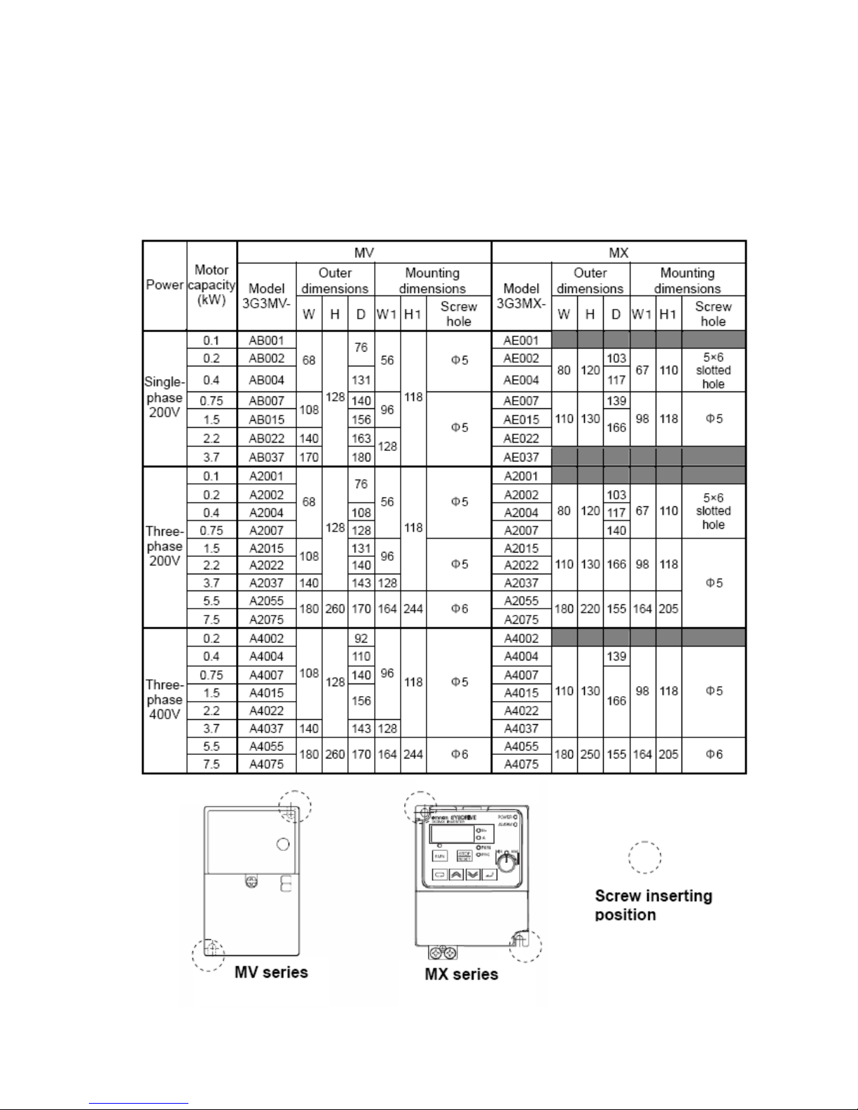
2. Main unit dimensions / mounting dimensions
・The outer dimensions and mounting dimensions of the MX drive are larger than the MV series.
Please note that the size value is larger than the MV depending on capacity.
・The mounting screw position on 3G3MV-AE002・AE004/A2002 to 2007 differs from the MV drive. Please be
careful when mounting (refer to the Figure below).
4
Page 5

3. Terminal Table
(1) Main circuit terminal
・Please note that MV and MX sometimes have terminals with different names.
MV MX Remarks
R/L1 R/L1
S/L2 S/L2
T/L3 T/L3
U/T1 U/T1
V/T2 V/T2
W/T3 W/T3
B1 P/+2
B2 RB
+1 +1 DC reactor connection terminal,
+2 P/+2 DC reactor connection terminal
-(minus) -(minus) DC reactor connection terminal
AC power input terminal
Motor output terminal
Braking resistor connection terminal
At DC power input: positive pole
5
Page 6
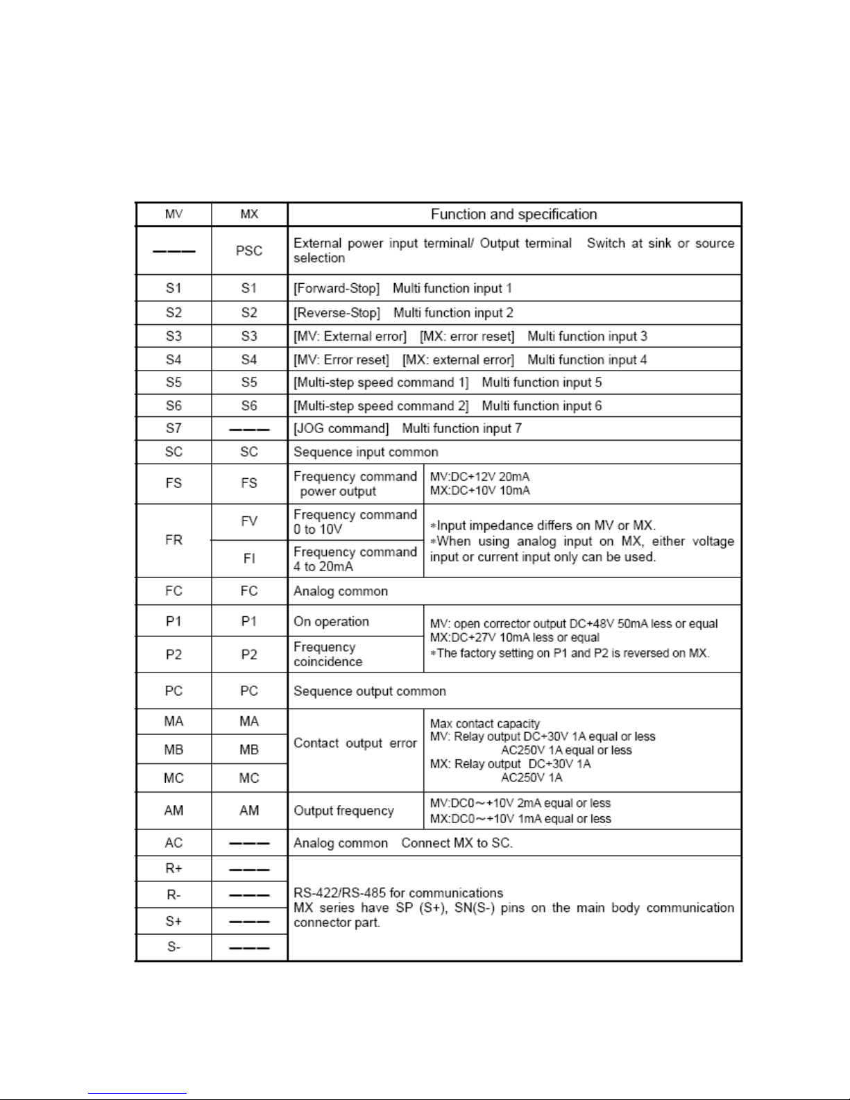
(2) Control circuit terminal
・ The terminal configurations and terminal names are different on the MV and MX drives.
・ The default value will display the multi function setting allocated on both MV and MX.
・ On the default setting, the control terminals of S3 and S4 on MV have switched to the ones on MX.
・ “―――” on the table indicates “no terminal”.
・Terminal block arrangement/ configuration
6
Page 7
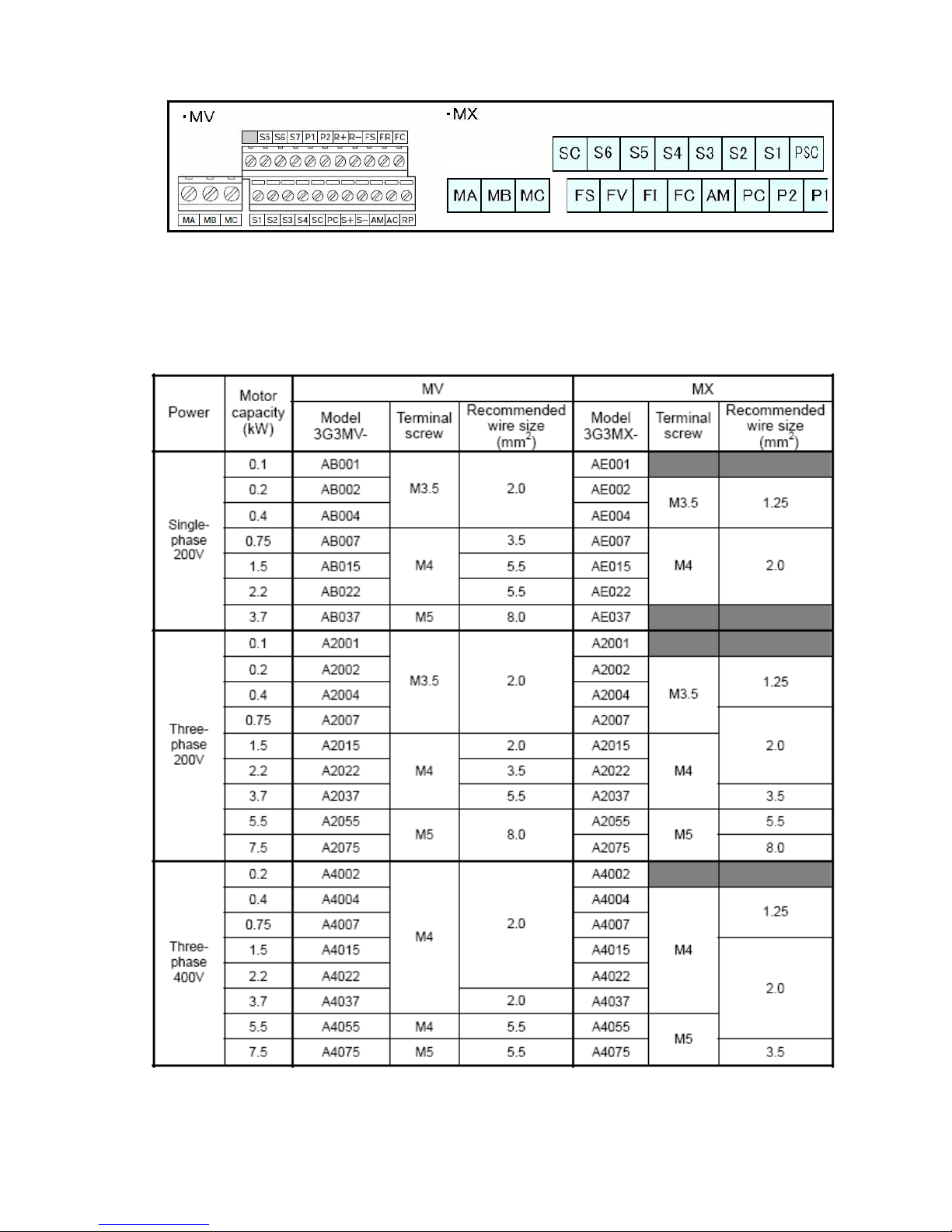
(3) Terminal size and wire size differences between MV and MX.
・Main circuit terminal size and electrical wire size
(Recommended wiring breaker and electromagnetic contactor will be same)
・Control circuit terminal size and electrical wire size
7
Page 8

The shape of terminal screw used for control circuit terminal differs on MV or MX.
MV: Minus
MX: Plus
Please be careful at wiring.
*1 When connecting 100V or 200V series on a relay output terminal block, please use 0.75mm
When equal or more 7 wires on control circuit terminal block. Please use shield wire of equal or less 0.5mm
The length to signal line armor is 5 to 6mm and connect it as an electrical wire. (If stranded wire, keep it from
coming apart).
The max armor outer dimensions of signal line(except alarm signal line) is equal ore less 2.00mm.
(Regarding mark tube and multi-conductor cable: mark tube at the fixed position equal or less 40mm from
connection end to sheath length. Set multi-conductor cable equal or less 40mm from connection end to
sheath length. If the line is too thick, terminal block cover possibly does not close).
2
.
2
.
8
Page 9

4. Standard damping resistance value and Minimum connectable resistance
value
・The conditions for calculating average deceleration torque on a single inverter differ on the MV series and
the MX series.
[MV] the average deceleration torque when decelerating in the shortest time
From 60Hz on a single unit motor
[MX] the average deceleration torque when deceleration in the shortest time
From 50Hz on a single unit motor.
・Braking resistor is not installed on inverter main body. Please use the optional braking resistor when large
regeneration torque is necessary.
Average deceleration torque on each capacity
・The minimum connectable resistance value differ. Please confirm the regeneration capacity of the capacity in
9
Page 10

bold. Depending on cases, please consider using a larger capacity drive.
Minimum connectable resistance value on each capacity
・ Following is the braking options used on MX.
10
Page 11

5 Parameter table
MV MX
Model
Function
No.
Set
value
No.
Set
value
Remarks
Parameter write-prohibit
selection/ initial constant
n001 1
b031
b084
01
00
b031:Parameter protection function
b084: Parameter initialization select
Control mode selection n002 0 A044 02
The default value of MX series is vector
control.
RUN command selection n003 0 A002 02
Frequency reference
selection
n004 0 A001 00
Stopping method selection n005 0 b091 00
Reverse rotation-prohibit
selection
n006 0 ――― ―――
STOP key enabled/
disabled selection
n007 0 b087 0 0
Frequency reference
selection on local mode
n008 0 ――― ―――
Operator frequency
setting method selection
n009 0 ――― ―――
Operation selection at
operator interruption
n010 0 ――― ―――
Maximum frequency
n011 60.0 A004 60.0
Maximum voltage n012 200.0 A082 200
Maximum voltage frequency
n013 60.0 A003 60.0
Middle output frequency
n014 1.5 A043 3.0
Middle output frequency
voltage
n015 12.0 A042 5.0
Minimum output frequency
n016 1 . 5 b082 0.5
Minimum output frequency
voltage
n017 12.0 ――― ―――
V/f pattern setting
∗Set middle output frequency and vol
ume with % to the max value.
Acceleration/Deceleration
setting unit
n018 0 ――― ―――
Ac c el e rat i on t ime 1 n019 10.0 F002 10.0
Deceleration time 1 n020 10.0 F003 10.0
Ac c el e rat i on t ime 2 n021 10.0 A092 15.00
De c el e rat i on t ime 2 n022 10.0 A093 15.00
S-shape
acceleration/deceleration
characteristics selection
n023 0
A097
A098
00
00
A097:Acceleration characteristics
A098:Deceleration characteristics
[b082]
[n016]
[A043]
[n014]
[A003]
[n013]
[A004]
[n011]
[MX]
[MV]
(Hz)
[A082][n012]
[A042][n015]
[---][n017]
[MX] [MV]
(V)
10
Page 12

11
MV MX
Model
Function
No.
Set
value
No.
Set
value
Remarks
Frequency reference 1
(Principal velocity
frequency)
n024 6 .00
F001
A020
0.0
setting frequency on F001 enables to set
the same value on A020.
Frequency reference 2 n025 0.00 A021 0.0
Frequency reference 3 n026 0.00 A022 0.0
Frequency reference 4 n027 0.00 A023 0.0
Frequency reference 5 n028 0.00 A024 0.0
Frequency reference 6 n029 0.00 A025 0.0
Frequency reference 7 n030 0.00 A026 0.0
Frequency reference 8 n031 0.00 A027 0.0
Inching frequency command n032 6.00 A038
6.0 The set range of MX is 0.00 to 9.99.
Upper frequency
reference limit
n033
100 A061 0.0
The default value of MX 0.0 shows “limit
function invalid”.
Lower frequency reference
limit
n034 0 A062 0.0
Frequency reference select/
reference unit selection
n035 0 b086 1. 0
Motor rated current n036
Var i es
with
capacity
b012
Rated
current
b012: set electronic thermal level.
Motor protection function
select
n037 0 b013 00
b013: set electronic thermal characteristics
Motor protection operation
time
n038 8 ――― ―――
Cooling fan operation select
(with cooling fan only)
n039 0 b092 0 1
Motor rotation direction
n040 0 F004 0 0
MV: corresponded to all operation
command
MX: Direction selection at pressing operator
RUN
Acceleration time 3
n041
10.0
――― ―――
Deceleration time 3
n042
10.0 ――― ―――
Acceleration time 4 n043 10.0 ――― ―――
Deceleration time 4 n044 10.0 ――― ―――
Page 13

12
MV MX
Model
Function
No.
Set
value
No.
Set
value
Remarks
Multi function input
selection 1
n050 1 C001 0 0
Multi function input
selection 2
n051 2 C002 0 1
Multi function input
selection 3
n052 3 C003 1 8
Multi function input
selection 4
n053 5 C004 12
Multi function input
selection 5
n054 6 C005 02
Multi function input
selection 6
n055 7 C006 0 3
Multi function input
selection 7
n056 1 0 ――― ―――
No setting is possible since the number of
multi function inputs of MX is 6.
Multi function output
selection 1
n057 0 C026 0 5
Multi function output
selection 2
n058 1 C021 0 0
Multi function output
selection 3
n059 2 C022 0 1
Frequency reference gain
n060 100
C081
C082
100.0
100.0
C081: Gain adjustment at voltage input
C082: Gain adjustment at current input
Frequency reference bias
n061 0
A011
A101
0.0
0.0
A011: Bias adjustment at voltage input
A101: Bias adjustment at current input.
Analog frequency reference
filter time constant
n062 0.10 A016 8
MV: Set filter time constant
MX: Set sampling frequency
(Not used) n063 ――― ――― ―――
Frequency reference loss
detection function
selection
n064 0 ――― ―――
Multi function analog
output : output type
selection
n065 0 ――― ―――
Multi function analog output
selection
n066 0 C028 00
Multi function analog output
gain
n067 1.0 0 b080 100
Multi function analog
voltage input gain
n068 100 ――― ―――
Multi function analog
voltage input bias
n069 0 ――― ―――
Multi function analog
voltage input: filter time
constant
n070 0.10 ――― ―――
Multi function analog current
input gain
n071 100 ――― ―――
Multi function analog current
input bias
n072 0 ――― ―――
Page 14

13
MV MX
Model
Function
No.
Set
value
No.
Set
value
Remarks
Multi function analog current
input filter time constant
n073 0.10 ――― ―――
Pulse train frequency
reference gain
n074 100 ――― ―――
Pulse train frequency
reference bias
n075 0 ――― ―――
Pulse train frequency
reference input filter time
constant
n076 0.10 ――― ―――
Multi function analog input
terminal function selection
n077 0 ――― ―――
Multi function analog input
terminal selection
n078 0 ――― ―――
Multi function analog input
frequency bias value
n079 10 ――― ―――
Carrier frequency n080
Var i es
with
capacity
b083 5.0
Operation after momentary
power interruption and
return selection
n081 0
Number of fault retries
n082
0
b001 to
b005
―――
Set b001=1or 2.
Execute error retry to over voltage
and over current at b005=0.
The numbers of retry is fixed at 3.
Jump frequency 1 n083 0.00 A063 0.0
Jump frequency 2 n084 0.00 A065 0.0
Jump frequency 3 n085 0.00 A067 0.0
Jump width n086 0.00
A064
A066
A068
0.5
MV: set output frequency for jump as n083
to 085 and set jump width to n086.
MX: set frequency command for jump as
A063・065・067. Set jump frequency width
on A064・066・068.
Accumulated operating
time select
n087 0 ――― ―――
Accumulated operating time n088 0
d016
d017
―――
MV: select monitoring time on n087 and
n088 displays cumulative operation time.
MX:d016:accumulated operation on RUN
d017:Power ON time
DC injection breaking
current
n089 50 A054 50
DC injection
breaking-to-stop time
n090 0.5 A055 0.5
DC injection breaking time
at startup
n091 0.0 ――― ―――
Stall prevention during
deceleration select
n092 0 b130 0 0
MX: set level on b131.
Stall prevention operation
level during deceleration
n093 170 b140 00
MX:ON/OFF setting only
Detection level is 160% fixed
Page 15

14
MV MX
Model
Function
No.
Set
value
No.
Set
value
Remarks
Stall prevention
operation level
n094 160 ――― ―――
Frequency detection level n095 0.00
C042
C043
0.0
0.0
C042:at acceleration C043:at deceleration
Over-torque detection
function level 1
n096 0 ――― ―――
Over-torque detection
function level2
n097 0 ――― ―――
Ov e r- t orq u e d e tec tio n le v el n098 160 C041
Rated
current
Over-torque detection time n099 0.1 ――― ―――
Up/down frequency memory n100 0 C101 00
Speed search
deceleration time
n101 2.0 ――― ―――
Speed search
operation level
n102 150 ――― ―――
Replaceable with starting at same
frequency on trip retry function.
Torque compensation gain n103 1.0 A046 1.0
Torque compensation
primary delay time constant
n104 0.3 ――― ―――
Torque compensation
excitation loss
n105
Var i es
with
capacity
――― ―――
Rated motor slip n106
Var i es
with
capacity
H006 100
Motor phase-to-phase
resistance
n107
Var i es
with
capacity
――― ―――
Motor leakage
Inductance
n108
Var i es
with
capacity
――― ―――
Tor q ue c o mp e nsa t io n lim i t n109 150 ――― ―――
Motor no load current n110
Var i es
with
capacity
――― ―――
Slip compensation gain n111 0.0
Slip compensation
Primary delay time constant
n112 2.0
A047
H006
100
100
Slip compensation select on
regeneration operation
n113 0 ――― ―――
(Not used) n114 ――― ――― ―――
Stall prevention operation
level automatic gradual
decrease function selection
n115 0 ――― ―――
Page 16

15
MV MX
Model
Function
No.
Set
value
No.
Set
value
Remarks
Acc/deceleration time select
at stall protection on
operation
n116 0 ――― ―――
Under torque detection
function select
n117 0 ――― ―――
Under torque detection level n118 10 ――― ―――
Under torque detection time n119 0.1 ――― ―――
Frequency reference 9 n120 0.00 A028 0.0
Fr e qu e ncy r ef e ren c e 1 0 n121 0.00 A029 0.0
Fr e qu e ncy r ef e ren c e 11 n122 0.00 A030 0.0
Fr e qu e ncy r ef e ren c e 1 2 n123 0.00 A031 0.0
Fr e qu e ncy r ef e ren c e 1 3 n124 0.00 A032 0.0
Fr e qu e ncy r ef e ren c e 1 4 n125 0.00 A033 0.0
Fr e qu e ncy r ef e ren c e 1 5 n126 0.00 A034 0.0
Fr e qu e ncy r ef e ren c e 1 6 n127 0.00 A035 0.0
PI D co n tro l se l ect n128 0 A071 00
Detection value adjustment
gain
n129 1.00 A075 1.00
MV: Adjust input level of target value
MX: Set percentage of feedback value and
display it on monitor d004.
Pr o po r tio na l g a in ( P) n130 1.0 A072 1.0
In t eg r al t ime ( I) n131 1.0 A073 1.0
Di f fer e nt i al t i me ( D) n132 0.00 A074 0.0
PID Offset adjustment n133 0 ――― ―――
In t eg r al( I ) u p per lim i t va lue n134 100 ――― ―――
PID first-order primary delay
time constant
n135 0.0 ――― ―――
Feedback loss detection
selection
n136 0 ――― ―――
Feedback loss detection
level
n137 0 C044 3.0
Feedback loss detection
level
n138 1.0 ――― ―――
MV: Execute the operation selected on
n136 when the status of less or equal
detection level set on n137 continues
longer than the time set up on n138.
MX: multi-function output terminal outputs
OD (PID deviation signal) when reaching
the level set on C044 (set multi function
output function “OD”).
Page 17

16
MV MX
Model
Function
No.
Set
value
No.
Set
value
Remarks
Energy saving control
selection
n139 0 ――― ―――
Energy saving control
coefficient K2
n140
Var i es
with
capacity
――― ―――
Energy saving voltage low
limit at 60Hz output.
n141 50 ――― ―――
Energy saving voltage lower
limit at 6Hz output
n142 12 ――― ―――
Power average time n143 1 ――― ―――
Probe operation voltage
limit
n144 0 ――― ―――
Prove operation control
voltage step at 100%.
n145 0.5 ――― ―――
Prove operation control
voltage step at 5%
n146 0.2 ――― ―――
Not used
n147
n148
――― ――― ―――
Pu l se t rai n in p ut s c al e n149 2500 ――― ―――
Multi function analog output
pulse train frequency
selection
n150 0 ――― ―――
RS-422/485
communication time over
detection selection
n151 0
C076
C077
02
0.00
∗C076:Select stop operation at time out
∗C077:Set the time of communication time
out
RS-422/485
communications frequency
reference/ monitor unit
selection
n152
0
―――
―――
RS-422/485
communications
Slave address
n153 00 C072 1
RS-422/485
communications
Baud rate select
n154 2 C071 04
RS-422/485
communications
Parity select
n155 0 C074 00
RS-422/485
communications
Send dwell
n156 10 C078 0
RS-422/485
communications
RTS control enabled/
disabled
n157 0 ――― ―――
Page 18

17
MV MX
Model
Function
No.
Set
value
No.
Set
value
Remarks
Motor code n158
Var i es
with
capacity
――― ―――
Energy saving voltage
upper limit at 60Hz output
n159 120 ――― ―――
Energy saving voltage
upper limit at 6Hz output
n160 16 ――― ―――
Power detection width for
probe operation switching
n161 10 ――― ―――
Power detection filter time
constant
n162 5 ――― ―――
PID output gain n163 1.0 ――― ―――
PID feedback
Input block selection
n164 0 A076 00
Not used n165 ――― ――― ―――
Input open phase
detection level
n166 0 ――― ―――
Input open phase
detection time
n167 0 ――― ―――
Output open phase
detection level
n168 0 ――― ―――
Output open phase
detection time
n169 0.0 ――― ―――
Enter command
operation select
n170 0 ――― ―――
DC injection breaking P
(proportional) gain
n173 83 ――― ―――
DC injection breaking
I(integral) gain
n174 0 ――― ―――
Low-speed carrier
frequency reduction
selection
n175 0 b150 00
Function specification differs on MV or MX.
Parameter copy function
selection
n176 Rdy ――― ―――
Parameter read prohibit
selection
n177 0 ――― ―――
Error log n178 ―――
d080
d081
d082
―――
Setting MV or MX is not possible only with
reference..
Software No. n179 ――― ――― ―――
Page 19

18
6 The differences between EV and JX: rated output capacity / current
and carrier frequency default value
MV MX
Power
Model
3G3MV-
Rated
output
capacity
(kVA)
Rated
output
current
(A)
Carrier
frequency
(kHz)
Carrier
frequency
at 10kHz
rate output
current(A)
Model
3G3MX
-
Rated
output
capacity
(kVA)
Rated
output
current
(A)
Carrier
frequency
(kHz)
Carrier
frequency
at 10kHz
rate output
current(A)
AB001 0.3 0.8
AB002 0.6 1.6 AE002 0.5 1.6
AB004 1.1 3.0 AE004 0.8 2.6
AB007 1.9 5.0
10
No
decrease
of rating
AE007 1.3 4.0
AB015 3.0 8.0 7.0 AE015 2.7 8.0
AB022 4.2 11.0 10.0 AE022 3.8 11.0
5.0
No
decrease
of rating
Single-
phase
200V
AB037 6.7 17.5
7.5
16.5
A2001 0.3 0.8
A2002 0.6 1.6 A2002 0.6 1.6
A2004 1.1 3.0 A2004 1.0 3.0
A2007 1.9 5.0
10
No
decrease
of rating
A2007 1.7 5.0
A2015 3.0 8.0 7.0 A2015 2.8 8.0
A2022 4.2 11.0 10.0 A2022 3.8 11.0
A2037 6.7 17.5 16.5 A2037 6.1 17.5
A2055 9.5 25.0 23.0 A2055 8.3 24.0
Three-
phase
200V
A2075 13.0 33.0
7.5
30.0 A2075 11.1 32.0
5.0
No
decrease
of rating
A4002 0.9 1.2 1.0
A4004 1.4 1.8 1.6 A4004 1.0 1.5
A4007 2.6 3.4 3.0 A4007 1.7 2.5
A4015 3.7 4.8 4.0 A4015 2.6 3.8
A4022 4.2 5.5 4.8 A4022 3.8 5.5
A4037 6.6 8.6 8.1 A4037 6.0 8.6
A4055 11.0 14.8
No
decrease
of rating
A4055 9.0 13.0
Three-
phase
400V
A4075 14.0 18.0
7.5
17.0 A4075 11.1 16.0
5.0
No
decrease
of rating
Page 20

Terms and Conditions of Sale
1. Offer; Acceptance. These terms and conditions (these "Terms") are deemed
part of all quotes, agreements, purchase orders, acknowledgments, price lists,
catalogs, manuals, brochures and other documents, whether electronic or in
writing, relating to the sale of products or services (collectively, the "Products
by Omron Electronics LLC and its subsidiary companies (“Omron”). Omron
objects to any terms or conditions proposed in Buyer’s purchase order or other
documents which are inconsistent with, or in addition to, these Terms.
2. Prices; Payment Terms.
out notice by Omron. Omron reserves the right to increase or decrease prices
on any unshipped portions of outstanding orders. Payments for Products are
due net 30 days unless otherwise stated in the invoice.
3. Discounts.
sent to Buyer after deducting transportation charges, taxes and duties, and will
be allowed only if (i) the invoice is paid according to Omron’s payment terms
and (ii) Buyer has no past due amounts.
4. Interest.
the maximum legal rate, whichever is less, on any balance not paid within the
stated terms.
5. Orders
6. Governmental Approvals.
costs involved in, obtaining any government approvals required for the importation or sale of the Products.
7. Taxes
real property and income taxes), including any interest or penalties thereon,
imposed directly or indirectly on Omron or required to be collected directly or
indirectly by Omron for the manufacture, production, sale, delivery, importation, consumption or use of the Products sold hereunder (including customs
duties and sales, excise, use, turnover and license taxes) shall be charged to
and remitted by Buyer to Omron.
8. Financial.
to Omron, Omron reserves the right to stop shipments or require satisfactor y
security or payment in advance. If Buyer fails to make payment or otherwise
comply with these Terms or any related agreement, Omron may (without liability and in addition to other remedies) cancel any unshipped portion of Products sold hereunder and stop any Products in transit until Buyer pays all
amounts, including amounts payable hereunder, whether or not then due,
which are owing to it by Buyer. Buyer shall in any event remain liable for all
unpaid accounts.
9. Cancellation; Etc.
unless Buyer indemnifies Omron against all related costs or expenses.
10. Force Majeure
resulting from causes beyond its control, including earthquakes, fires, floods,
strikes or other labor disputes, shortage of labor or materials, accidents to
machinery, acts of sabotage, riots, delay in or lack of transportation or the
requirements of any government authority.
11. Shipping; Delivery.
a. Shipments shall be by a carrier selected by Omron; Omron will not drop ship
b. Such carrier shall act as the agent of Buyer and delivery to such carrier shall
c. All sales and shipments of Products shall be FOB shipping point (unless oth-
d. Delivery and shipping dates are estimates only; and
e. Omron will package Products as it deems proper for protection against nor-
12. Claims.
Products occurring before delivery to the carrier must be presented in writing
to Omron within 30 days of receipt of shipment and include the original transportation bill signed by the carrier noting that the carrier received the Products
from Omron in the condition claimed.
13. Warranties
Products will be free from defects in materials and workmanship for a period of
twelve months from the date of sale by Omron (or such other period expressed
in writing by Omron). Omron disclaims all other warranties, express or implied.
(b) Limitations
EXPRESS OR IMPLIED, ABOUT NON-INFRINGEMENT, MERCHANTABIL-
Cash discounts, if any, will apply only on the net amount of invoices
Omron, at its option, may charge Buyer 1-1/2% interest per month or
. Omron will accept no order less than $200 net billing.
. All taxes, duties and other governmental charges (other than general
If the financial position of Buyer at any time becomes unsatisfactory
except in “break down” situations.
constitute delivery to Buyer;
erwise stated in writing by Omron), at which point title and risk of loss shall
pass from Omron to Buyer ; provided that Omron shall retain a security interest in the Products until the full purchase price is paid;
mal handling and extra charges apply to special conditions.
Any claim by Buyer against Omron for shortage or damage to the
. (a) Exclusive Warranty. Omron’s exclusive warranty is that the
All prices stated are current, subject to change with-
Buyer shall be responsible for, and shall bear all
Orders are not subject to rescheduling or cancellation
. Omron shall not be liable for any delay or failure in delivery
Unless otherwise expressly agreed in writing by Omron:
. OMRON MAKES NO WARRANTY OR REPRESENTATION,
ITY OR FITNESS FOR A PARTICULAR PURPOSE OF THE PRODUCTS.
BUYER ACKNOWLEDGES THAT IT ALONE HAS DETERMINED THAT THE
PRODUCTS WILL SUITABLY MEET THE REQUIREMENTS OF THEIR
")
INTENDED USE. Omron further disclaims all warranties and responsibility of
any type for claims or expenses based on infringement by the Products or otherwise of any intellectual property right. (c) Buyer Remedy
gation hereunder shall be, at Omron’s election, to (i) replace (in the form
originally shipped with Buyer responsible for labor charges for removal or
replacement thereof) the non-complying Product, (ii) repair the non-complying
Product, or (iii) repay or credit Buyer an amount equal to the purchase price of
the non-complying Product; provided that in no event shall Omron be responsible for warranty, repair, indemnity or any other claims or expenses regarding
the Products unless Omron’s analysis confirms that the Products were properly handled, stored, installed and maintained and not subject to contamination, abuse, misuse or inappropriate modification. Retur n of any Products by
Buyer must be approved in writing by Omron before shipment. Omron Companies shall not be liable for the suitability or unsuitability or the results from the
use of Products in combination with any electrical or electronic components,
circuits, system assemblies or any other materials or substances or environments. Any advice, recommendations or information given orally or in writing,
are not to be construed as an amendment or addition to the above warranty.
See http://www.omron247.com or
li
shed information.
14. Limitation on Liability; Etc
FOR SPECIAL, INDIRECT, INCIDENTAL, OR CONSEQUENTIAL DAMAGES,
LOSS OF PROFITS OR PRODUCTION OR COMMERCIAL LOSS IN ANY
WAY CONNECTED WITH THE PRODUCTS, WHETHER SUCH CLAIM IS
BASED IN CONTRACT, WARRANTY, NEGLIGENCE OR STRICT LIABILITY.
Further, in no event shall liability of Omron Companies exceed the individual
price of the Product on which liability is asserted.
15. Indemnities
their employees from and against all liabilities, losses, claims, costs and
expenses (including attorney's fees and expenses) related to any claim, investigation, litigation or proceeding (whether or not Omron is a party) which arises
or is alleged to arise from Buyer's acts or omissions under these Terms or in
any way with respect to the Products. Without limiting the foregoing, Buyer (at
its own expense) shall indemnify and hold harmless Omron and defend or settle any action brought against such Companies to the extent based on a claim
that any Product made to Buyer specifications infringed intellectual property
rights of another party.
16. Property; Confidentiality.
sive property of Omron Companies and Buyer shall not attempt to duplicate it
in any way without the written permission of Omron. Notwithstanding any
charges to Buyer for engineering or tooling, all engineering and tooling shall
remain the exclusive property of Omron. All information and materials supplied
by Omron to Buyer relating to the Products are confidential and proprietary,
and Buyer shall limit distribution thereof to its trusted employees and strictly
prevent disclosure to any third party.
17. Export Controls.
licenses regarding (i) export of products or information; (iii) sale of products to
“forbidden” or other proscribed persons; and (ii) disclosure to non-citizens of
regulated technology or information.
18. Miscellaneous
and no course of dealing between Buyer and Omron shall operate as a waiver
of rights by Omron. (b) Assignment
without Omron's written consent. (c) Law.
law of the jurisdiction of the home office of the Omron company from which
Buyer is purchasing the Products (without regard to conflict of law principles). (d) Amendment
Buyer and Omron relating to the Products, and no provision may be changed
or waived unless in writing signed by the par ties. (e) Severability
sion hereof is rendered ineffective or invalid, such provision shall not invalidate
any other provision. (f) Setoff
against the amount owing in respect of this invoice. (g) Definitions
herein, “including
nies” (or similar words) mean Omron Corporation and any direct or indirect
subsidiary or affiliate thereof.
. Buyer shall indemnify and hold harmless Omron Companies and
Buyer shall comply with all applicable laws, regulations and
. (a) Waiver. No failure or delay by Omron in exercising any right
. These Terms constitute the entire agreement between
” means “including without limitation”; and “Omron Compa-
contact your Omron representative for pub-
. OMRON COMPANIES SHALL NOT BE LIABLE
Any intellectual property in the Products is the exclu-
. Buyer may not assign its rights hereunder
These Terms are governed by the
. Buyer shall have no right to set off any amounts
. Omron’s sole obli-
. If any provi-
. As used
Certain Precautions on Specifications and Use
1. Suitability of Use. Omron Companies shall not be responsible for conformity
with any standards, codes or regulations which apply to the combination of the
Product in the Buyer’s application or use of the Product. At Buyer’s request,
Omron will provide applicable third party certification documents identifying
ratings and limitations of use which apply to the Product. This information by
itself is not sufficient for a complete determination of the suitability of the Product in combination with the end product, machine, system, or other application
or use. Buyer shall be solely responsible for determining appropriateness of
the particular Product with respect to Buyer’s application, product or system.
Buyer shall take application responsibility in all cases but the following is a
non-exhaustive list of applications for which particular attention must be given:
(i) Outdoor use, uses involving potential chemical contamination or electrical
interference, or conditions or uses not described in this document.
(ii) Use in consumer products or any use in significant quantities.
(iii) Energy control systems, combustion systems, railroad systems, aviation
systems, medical equipment, amusement machines, vehicles, safety equipment, and installations subject to separate industry or government regulations.
(iv) Systems, machines and equipment that could present a risk to life or property. Please know and observe all prohibitions of use applicable to this Product.
NEVER USE THE PRODUCT FOR AN APPLICATION INVOLVING SERIOUS
RISK TO LIFE OR PROPERTY OR IN LARGE QUANTITIES WITHOUT
ENSURING THAT THE SYSTEM AS A WHOLE HAS BEEN DESIGNED TO
ADDRESS THE RISKS, AND THAT THE OMRON’S PRODUCT IS PROPERLY RATED AND INSTALLED FOR THE INTENDED USE WITHIN THE
OVERALL EQUIPMENT OR SYSTEM.
2. Programmable Products.
user’s programming of a programmable Product, or any consequence thereof.
3. Performance Data
and other materials is provided as a guide for the user in determining suitability and does not constitute a warranty. It may represent the result of Omron’s
test conditions, and the user must correlate it to actual application requirements. Actual perfor mance is subject to the Omron’s Warranty and Limitations
of Liability.
4. Change in Specifications
changed at any time based on improvements and other reasons. It is our practice to change part numbers when published ratings or features are changed,
or when significant construction changes are made. However, some specifications of the Product may be changed without any notice. When in doubt, special part numbers may be assigned to fix or establish key specifications for
your application. Please consult with your Omron’s representative at any time
to confirm actual specifications of purchased Product.
5. Errors and Omissions.
checked and is believed to be accurate; however, no responsibility is assumed
for clerical, typographical or proofreading errors or omissions.
Omron Companies shall not be responsible for the
. Data presented in Omron Company websites, catalogs
. Product specifications and accessories may be
Information presented by Omron Companies has been
Page 21

Specifications subject to change without notice.
Printed in the U.S.A.
OMRON ELECTRONICS LLC
1 Commerce Drive
Schaumburg, IL
60173
847.843.7900
For US technical support or
other inquiries: 800.556.6766
OMRON CANADA, INC.
885 Milner Avenue
Toronto, Ontario M
1B 5V8
416.286.6465
OMRON ON-LINE
Global- www.omron.com
USA - www.omron247.com
Canada - www.omron.ca
Brazil - www.omron.com.br
Latin America - www.espanol.omron.com
MIG_MAN_3G3MVTO3G3MX ©2008 OMRON ELECTRONICS LLC
UNITED STATES
To locate a Regional Sales Oce, local Distributor or
to obtain product information, call: 847.843.7900
MEXICO SALES OFFICES
Mexico, D.F. 555.660.3144
Ciudad Juárez 656.623.7083
Monterrey, N.L 818.377.4281
Querétaro 442.135.4510
BRAZIL SALES OFFICE
Sao Paulo 55.11.2101.6310
ARGENTINA SALES OFFICE
Cono Sur 54.114.787.1129
OTHER LATIN AMERICAN SALES
mela@omron.com
 Loading...