How it Works
Log In / Sign Up
Buy Points
How it Works
FAQ
Contact Us
Questions and Suggestions
Users
OMNIREL
Loading...
J
JANTXV1N6771R
2
JANTXV1N6772
2
JANTXV1N6772R
2
JANTXV1N6773
2
JANTXV1N6773R
2
JANTXV1N6774
JANTXV1N6775
JANTXV1N6776
JANTXV1N6777
JANTXV1N6778
JANTXV1N6779
JANTXV2N6764
JANTXV2N6766
JANTXV2N6768
JANTXV2N6770
JANTXV2N6796
JANTXV2N6798
JANTXV2N6800
JANTXV2N6802
JANTXV2N7218
JANTXV2N7219
JANTXV2N7221
JANTXV2N7222
JANTXV2N7224
JANTXV2N7225
JANTXV2N7227
JANTXV2N7228
O
OM100F60SB
OM100L60CMIS
OM10N100NK
OM11N55SA
OM11N60SA
OM120L60SB
OM1320MM
OM1320N2M
OM1320NKM
OM1320NMM
OM1320STM
OM1321N2M
OM1321NMM
OM1321NTM
OM1321SMM
OM1321STM
OM1322N2M
OM1322NMM
OM1322NTM
OM1322SMM
OM1322STM
OM1323N2M
3
OM1323NKM
3
OM1323NMM
3
OM1323NTM
3
OM1323SMM
3
OM1323STM
3
OM1324N2M
OM1324NMM
OM1324NTM
OM1324SMM
OM1324STM
OM1325N2M
OM1325NKM
OM1325NMM
OM1325NTM
OM1325SMM
OM1325STM
OM1326N2M
OM1326NKM
OM1326NMM
OM1326NTM
OM1326SMM
OM1326STM
OM1327N2M
OM1327NKM
OM1327NMM
OM1327NTM
OM1327SMM
OM1327STM
OM150F120CMA
OM150F120CMC
OM150F120CMD
OM150L120CMA
OM150L120CMC
OM150L120CMD
OM1805N2M
OM1805N5M
OM1805NKM
OM1805NMM
OM1805NTM
OM1805STM
OM1812N2M
OM1812N5M
OM1812NKM
OM1812NMM
OM1812NTM
OM1812STM
OM1815N2M
OM1815N5M
OM1815NKM
OM1815NMM
OM1815NTM
Loading...
Loading...
Nothing found
OM1323NMM
Datasheet
4 pgs
39.04 Kb
0
Technical data
4 pgs
37.85 Kb
0
Technical data
4 pgs
38.05 Kb
0
Table of contents
Loading...
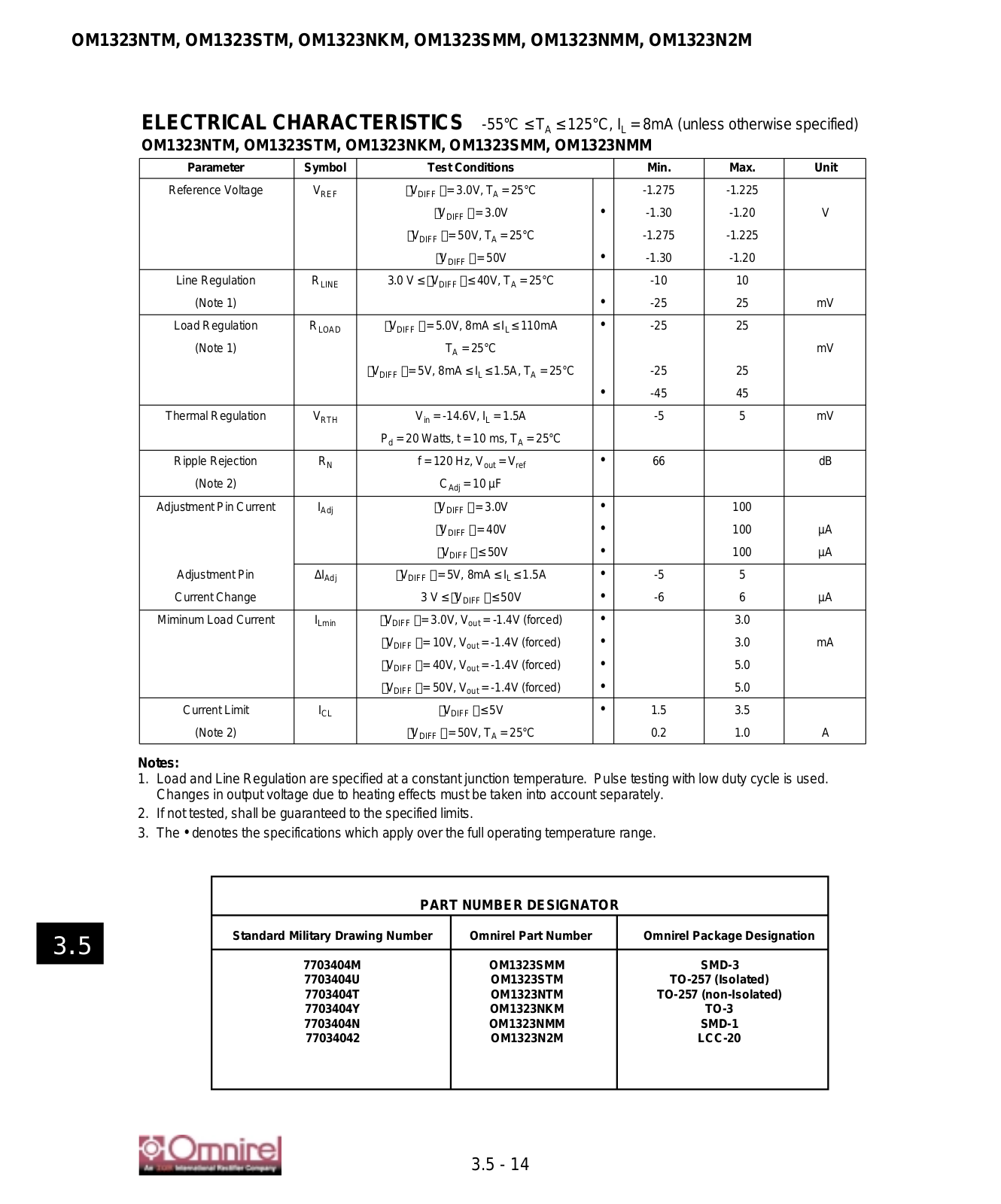
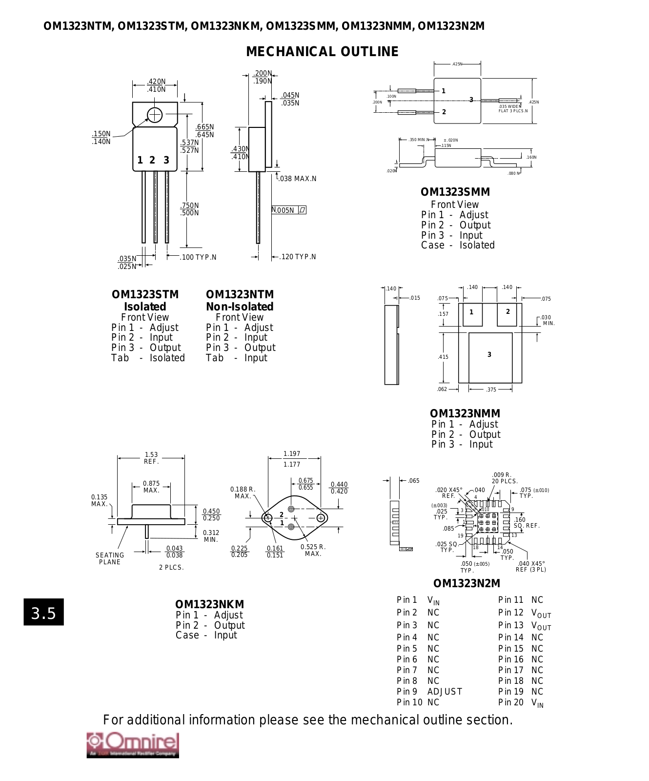
OMNIREL OM1323NKM, OM1323SMM, OM1323STM, OM1323NMM, OM1323N2M Datasheet
...
OMNIREL OM1323NKM, OM1323SMM, OM1323STM, OM1323NMM, OM1323N2M, OM1323NTM Datasheet
Download
Specifications and Main Features
Frequently Asked Questions
User Manual
Download
Loading...
+
hidden pages
Unhide
You need points to download manuals.
1 point = 1 manual.
You can buy points or you can get point for every manual you upload.
Buy points
Upload your manuals