

Page 1

Cutting Edge
Unity AM Broadcast Processor
Cutting Edge Technologies
2101 Superior Avenue
Cleveland, OH 44114 • USA
(216) 241-3343• Fax (216) 241-4103
Manual Version: Preliminary AM (4.0.0)
Jan 1995
1
Page 2

A letter from Frank Foti,
Dear Cutting Edge Customer,
Personally, I would like to thank you for selecting the Unity AM! What you have in your possession
right now is, not only years of research and development, but years of my passion for broadcast audio
processing. Add to that, a multitude of ideas, thoughts, and opinions of the many associates, friends,
and yes, even foes that I have encountered along the way! Who knows maybe even you yourself have
at sometime helped with a suggestion or idea! Again my heartfelt thanks!
You and I share a good common bond, radio! Before beginning Cutting Edge in 1988, I too was on
your side of the fence, in radio. As a broadcast engineer, I can totally relate to the day to day life in a
radio station. I have been there in the trenches just like you are right now! That’s why I am so excited
about the Unity AM, because someone designed it in the trenches, for radio, in radio!
Early concepts and ideas for this project actually began in the early 1980’s while I was enjoying the
life of great Album Rock at WMMS-FM, the Home of the Buzzard, right here in Cleveland! A brief
stint in San Francisco at Country music KSAN-FM and KNEW-AM gave me the opportunity to hone
my processing skills on something other than Rock-N-Roll! But the true test of ability, and far and
away the most pleasure and success, was achieved at that tiny Flamethrower atop the Empire State
Building, WHTZ-FM, better known as Z-100!
As a designer, engineer, and user, I know only too well how subjective audio processing is. There is
no right way, or wrong way to do it. As the sneaker manufacture Nike would say, “Just Do it”. (I
love the “Can Do” attitude!) We all know when it does not sound right, but to just “get it right” can
take quite an effort. So as you proceed with the installation of our product, I can only hope that you
will approach this endeavor with an open mind, patience, and time. Why? Because sometimes what
you desire, and what you initially receive may be two different things altogether!
For the majority of our customers, the Unity AM has made a big difference right off the bat. But I’d
be lying if I told you that, just by installing the Unity AM, your station would immediately be far and
above all the rest. It may take some time, but fear not, our goal is to get you to that point!
Well, enough of carrying on about myself. Here is where I would like to acknowledge the “known”
many who helped in delivering to you the Unity AM: Mozie, my Family, Pete Townshend, Steve
Church, Neil Glassman, Raymond Douglas Davies, Matthew Connor, David Reaves, M.D.D., David
“Zeke” Booth,“Don” Corleone, Doug Howland, Cate Cowan, John Granchi, F.Joseph Foti, Margot
Daly, Kevin Nosé, Dan Mettler, Marc Augis, Phillipe Legros, Bob Martin, Mark Hoageson, Mike
Maczuzak, Bruce Vanek, Don Coulter, Todd Linderman, Mary Dennis, Roz Brazleton, Danielle
Kreinbrink, Dee Oulds, Rich Matanowitch, Tom Petty, Madonna, John Alan, Judy Chamberlain,
Carlos Baerga, Dwayne Burlison, Paula Abdul, Emmylou Harris, Dean Thacker, Christine McVie, the
Cleveland Orchestra, The Who, Don Williams, the Bellamy Bros, Hiroshima, Frank Sinatra, Amy
Grant, Janet Jackson, The Kinks, Geary Morrill, Barry Thomas, Bonnie Riatt, James & Mary Anne
2
Page 3

Duffy, Quincy Jones, Bernie Kosar, Dorothy Fuldhiem, Billy Joel, Roxette, Chief Wahoo, Dire
Straits, Jack Barnes, Steve Pepe, Wickliffe Sr. High, and the many, many individuals who helped
make this project a reality!
Kindest Regards,
Frank Foti
Jan 1995
3
Page 4

About this manual
You have just opened the carton of a one of the most sophisticated pieces of broadcast audio
equipment. And we know how you feel. You don’t want to sit around a read a manual. You want to
plug it in and hear what it can do. You want to start pushing all the buttons and exploring the full
range of processing possibilities the Unity AM presents. We know how you feel, because when we
get a new, expensive toy, we feel the same way.
As much as we understand your excitement, we ask you to please try to demonstrate some selfcontrol.
This manual is designed to first introduce you to the capabilities of the Unity AM and then clearly
instruct you on its installation and operation. (Unlike most other manuals, large sections don’t even
require you to be sitting in front of the product.) We hope you will take the time to read the manual.
We trust you will enjoy it and that it will provide you with new and useful information on audio
processing.
Not yet convinced to wait a few hours? OK, here is where we have to warn you that we are not
responsible for anything that may happen to the Unity AM or the equipment to which you connect it
or to your station’s on-air sound or to your job if you do not read the manual.
4
Page 5

Table of Contents
Introduction 1
A little history
Just what the world needs, another audio processor
A word about loudness
The bottom line
Unity AM Overview 11
Unified Processing
User interface
Processing functions
Special features
Processing Concepts 15
Why our processor sounds better
Processing designed for the ears
Feedforward control
Quality versus loudness
Keep and open mind
Installation 21
Clarify your objectives
Available time
Installation considerations
Installation checklist
Mounting and connections
Setting pre-emphasis
Rear panel connections
Setting de-emphasis
Operation 32
The obvious
The LCD display
The jog wheel and buttons
Security
The real time clock
Orientation to the Main Menus
Setting the Unity AM input levels
Setting the Unity AM output levels
5
Page 6

The Processing Display 42
Input level meters
Wide Band AGC display
Level indicators
Limiter indicators
Display Interpretations
Processing Presets 46
Loading factory presets
Before you make adjustments to the presets
Modifying and adding presets
Loading user added presets
Updating user added presets
Deleting user added presets
Renaming user added presets
Main Menu Reference 54
Leveler Menu
Limiter Menu
Clipper Menu
Other Menu
In Case of Difficulty
Technical Descriptions 69
Troubleshooting Guide 81
Appendix 83
Remote Operation
Worksheets
Schematics
6
Page 7

Introduction
A little history
Like most of us with a passion for radio, Frank Foti started young. He was six years old when he first
dismantled and successfully reassembled his AM/FM radio. (His father is a little vague about how
many radios he took apart before he figured out how to put them back together.) By the time he was a
teenager, Frank was building Heathkits in his basement and, as a high school senior, designed and
built his own stereo system. After his high school graduation, Frank received a full scholarship to a
Cleveland, Ohio broadcasting school and earned his FCC First Class Radio Operator’s license in
1974.
His first job was with WELW, a small AM station located in Willoughby, Ohio. He was not only the
engineer, but also wore the hats of production director, morning disc jockey, play-by-play announcer,
and music director. When the grass needed cutting, he did that too! Honestly!!
In 1978, after answering a blind ad in Broadcasting , Frank was hired as Assistant Engineer at Malrite
Communications’ WHK/WMMS in Cleveland. This was more than just a better position at a bigger
station. For a rock & roll junkie like Frank, working at legendary album rock station WMMS was a
dream come true. When his boss was fired, Frank was promoted to Chief Engineer of the combo.
Frank did more than hone his engineering skills during the three years he spent at WHK/WMMS. He
began to explore processing, the art and science of enhancing audio and tailoring sound to fit
programming needs. It was here in Cleveland that Frank first tinkered with various processing
theories and “hot rodding” existing audio components.
In 1981, Malrite shipped Frank west to be Chief Engineer at country formatted KNEW/KSAN in San
Francisco. But the “city by the bay” was not his only assignment. Frank was flown to several stations
in the group to work on their processing chains. He gained experience in a wide variety of formats
and every station he visited experienced a ratings increase due in part to Frank’s processing.
In July of 1983, Frank was assigned to New York to be Chief at Malrite’s just purchased WHTZ-FM
(Z-100). Frank, along with a team that included programming wizard Scott Shannon, had the
responsibility of pulling the lowest rated station in the market out of the basement.
When Z-100 went on the air one month later, it skyrocketed from worst to first in just 74 days! Z100’s rise to the top was due to three factors: the format, the promotion, and the sound. Frank
combined several off-the-shelf processing products with some of his own inventions to create a larger
than life sound. (Frank borrows the word of Roger Daltry of The Who to describe the sound as
“getting punched in the nose and having somebody say I love you.”)
In 1985, Frank started to sell his first product to other engineers. The Vigilante multi-band limiter
7
Page 8

was initially sold by word of mouth. Stations that used the Vigilante kept this “secret weapon” behind
security covers so that the competition would not know what they were using. Frank discovered that
radio stations with the most successful audio chains (and the improved ratings) were the ones that had
all the separate components working in concert. Every part of the system had to be tuned for
maximum benefit; the sum of all the parts.
Frank returned to Cleveland in 1987 to become Malrite’s corporate Director of Engineering and
supervise the technical aspects of its seven radio properties. A “hands-on” manager, Frank traveled
the country to work with his engineers. Processing remained his primary interest and he was
frequently solicited to consult with other stations. His reputation as radio’s number one expert in
broadcast processing was now well established.
At home, Frank kept tinkering. And the tinkering soon became serious research. What he learned
from scores of engineers and programmers and from listening to stations all over the country was that
radio could sound better. And that better sounding radio meant more listeners.
Frank left Malrite in June of 1988 to create his own company and called it Cutting Edge
Technologies. More traveling, more consulting, and more research in the basement. Frank knew what
kind of processor radio demanded. And in 1994, he delivered it. The Unity AM.
Just what the world needs, another audio processor
Next to the fates and fortunes of local sports teams, nothing causes more arguments at radio stations
than processing.
In one corner there is the group who wants to burn a hole in the dial. In this day of high octane,
“Tastes Great… Less Filling,” extremely competitive, kill for the last dollar radio, the tendency in
many cases, has been towards creating a behemoth over-the-air. Utilizing as much of the latest,
greatest, tweaked, modified, and super-charged products available, we crank them up until we achieve
a sound that is “louder than anyone can ever be, but is totally clean.”
Who are we kidding? Hopefully, by now, we all know that all this does is create the potential for
fatigue, tune-out, and decreased time spent listening. The bottom line is that the listeners go
somewhere else.
On the other side of the debate are the sonic purists who want to transparently reproduce the source
material, just as it was recorded. Too little processing can be as bad as too much processing. Listeners
are more sophisticated and in the age of CDs (and now MDs) they know what sounds good. The
transmission chain and the receiving radios significantly effect audio dynamics and quality. It takes
careful, adequate processing to keep music sounding, well, musical.
The main reason this debate exists is that the processors you have been using don’t let you get the
8
Page 9

sound you want and need for your station. Yes, they sound all right in most circumstances and each
processor does have a sweet spot that performs satisfactorily in many circumstances. But they also
have built-in limits on what you can creatively accomplish. This, however, is the real world of
competitive radio… you can’t afford to sound “all right.” You have to stand out on the dial. With
traditional processors, whether you crank the processing up or down, you lose musicality.
Until Frank Foti (with the help of a couple of hundred radio engineers, programmers, and managers)
designed the Unity AM, you had only two options. Live with what you had or add another processor
to the chain. Or perhaps two more processors. Or perhaps… well, you get the idea. Adding on to the
processing chain was the way Cutting Edge got started. But it is not where we ended.
Frank determined that, when the optimum sound could not be achieved in a multiple box processing
system, the weakness was often the inability of the audio chain, as a system, to work in an integrated
manner. The strengths of one box did not always compensate for the deficiencies of the others.
The bottom line was that the world did need another audio processor. A device that has an open,
accurate sound over the full range of processing. It took Frank a long time to get the Unity AM right.
The proof that he got it right is the way the Unity AM sounds.
A word about loudness
Making this confession is a little like telling your parents you dented the car. But here it goes.
It is OK for your station to be loud. Very loud.
In the past, loudness was a problem due to the limitations of the processors you had available to you.
If you processed more heavily, then you either had to adjust your single box outside of its “safe”
range or use multiple boxes and risk their conflicting with each other.
Frank Foti and the Unity AM have changed all of that. Frank knows how to get a station sounding
loud without the artifacts or grunge created by your current processor when you try to make it loud.
And he knows how to make loud an option for all formats.
One more confession. It is also OK for your station to not sound loud. Because the Unity AM has
given you the choice. Our intention is to provide you with a system that will maximize the audio
quality of your signal, yet at the same time maintain your competitive requirements.
The bottom line
The Unity AM is unique in its approach to audio processing. It sounds better and is easier to use than
any other processor available.
9
Page 10

And how has the market reacted? As we look back over the past few years, the reaction has not been
unlike that to other “edge of technology” products like the original Apple computer.
• First, the Unity AM was ignored.
• Then it was accused (by other processing manufacturers) of being ineffective.
• Gradually, it was accepted by users with tolerance for risk and novelty.
• And now the Unity AM, is being accepted by large numbers of users.
You won’t find the Unity AM on the air at every station. But at the stations where it is installed, you
will find engineers, programmers, and managers happier than ever with their on-air sound.
Today, Cutting Edge is more than just Frank Foti. While Frank is glad to have someone else build the
boxes and keep the books, he’s still a busy guy. And we don’t mean spends the summers watching
Cleveland Indian games. No, he is still working on new ways to improve the sounds of broadcast
audio. And he is still spending a few hours each day talking with other broadcasters.
If your processing has you baffled, or you think you have a system that sounds better than Frank’s,
give him at call. The number is (216) 241-3343. His fax number is (216) 241-4103 if you are located
outside of the United States or a shy person. He’s a good talker and a great listener.
10
Page 11

Unity AM Overview
Unified Processing
We reassembled the pieces of the processing puzzle to get more out of the system as a whole; sort of
rearranging the furniture to get better use of the room. We call it Unified Processing. This
arrangement allows us to “unify” all functions of a broadcast audio chain into one package. In one
seven-inch tall chassis is the processing flexibility and power of at least three, and as many as six,
different pieces of equipment.
To help you get begin to adjust a processor that sounds great at all settings, Frank has provided
presets for a number of formats and programming requirements. These are used as a starting point for
your processing adjustments. Once you have found a setting you like, there are fifty user memory
locations provided for safe keeping. Comparing two setups is as easy as pushing a button.
User interface
Total operation of this system is accomplished through microprocessor control. With the Unity AM,
we have strayed from the conventional methods of operation. Gone are mechanical switches and pots.
In their place are a button pad, jog wheel, and LCD screen. Through user menus, you can achieve
better flexibility as well as rapidly store and retrieve settings.
In designing our user menus, we have avoided creating too many “layers” that would require
excessive navigation. Most processes and functions are accessed in three steps and the menus are
arranged in a logical manner that can be learned in minutes.
The Unity AM presents extensive set-up metering in the Processing Display. At all times, you can see
the activity of all processing functions so that you can determine the overall effect of any changes you
make. Our display is uniquely designed to provide a significant amount of easy to interpret
information.
Processing functions
The Unity AM provides eight processing functions, all are operated by a single control interface.
When you create a processing setting, you have the advantage of doing so for every part of your
processing chain.
The Unity AM’s eight processing functions are:
1) Selectable Wide Band AGC that reacts as if it was a “slow hand” on the output of the audio
console so that the levels coming into the Unity AM are always within a consistent window.
11
Page 12

This slow acting gain control circuit provides ±10dB of leveling. Imagine, if you will, someone
that would continually insure that the output of the audio console was always within a specific
level. The “platform leveling” control circuit for the AGC is intelligent enough to know that if the
incoming audio level is correct it will shut down its operation and wait until gain correction is
needed. The AGC is therefor only operating when needed, eliminating the constant seeking of
unneeded level changes.
2) Selectable Phase Rotator circuits that, when utilized, can assist in eliminating vocal distortion
during periods of heavier processing needs.
These specialized delay circuits create a “flywheel” effect on a certain range of frequencies. In this
case, audio within the main vocal range of 300Hz to 2kHz will change in phase as frequency
increases through the stated passband.
The reason we incorporate phase rotators is a problem created by the human voice. Most human
voices are asymmetrical in nature, meaning one side of the waveform is larger than the other. The
delay circuits of the phase rotators synthesize the symmetry of the waveform for vocal audio
through the passband. By doing this, the upper and lower crests of the vocal waveform are
processed more evenly.
For heavier processing situations, use of the phase rotators helps cut down on clipper induced
distortion on voices. For lighter processing requirements, the phase rotators can be defeated.
3) Selectable and adjustable low frequency Bass Enhancer circuit that provides a deep, full, and rich
texture to the bass line.
This is not just another low frequency equalizer. This section provides up to a 12dB boost to the
bass frequencies as well as the harmonic rich sub-bass region. The enhancement scheme used here
generates that deep, rich, and full low end that is sought after by so many contemporary
programmers. Unlike the use of conventional equalizers, there is no exaggeration of the upper low
frequency range causing the bass to sound unnatural and “tubby.”
4) The Selectable Matrix Processing Option allows the Unity AM to operate in either discrete
left/right or matrixed L+R/L-R processing for AM Stereo broadcasting. For detailed explanation
about matrix processing please refer to the technical description in the back of this manual.
5) Phase linear 4-way Adjustable Crossover Networks that allow all processing to be tailored to
any format requirement. This network provides perfect linearity as well as ±.5dB of flat response
when summed back together. Frequency response along with harmonic integrity are totally
maintained with this network. Since the crossover frequencies are adjustable, all crossover points
can be tuned for the appropriate programming format.
12
Page 13

6) Four band Processor/Leveler that “intelligently” levels each audio band in an effort to generate a
high modulation average, while at the same time creating spectral consistency.
Our unique leveler circuit actually “learns” what it needs to know about the incoming audio signal,
makes some decisions on what to do, feeds the information forward to a dynamically adjustable
gain block, and then makes whatever any necessary changes. All functions are performed in the
digital domain.
This feedforward approach allows the signal processor to operate at a constant ratio. The benefit
is consistent leveling for whatever amount of processing employed. This is the key reason why the
leveler is almost always in its “sweet-spot” of operation. Also because each section works off a
platform, the control circuitry has the ability to produce ±7.5dB of RMS leveling. Since all
operation is RMS, only the average level is analyzed and corrected. This yields a better
modulation average for each audio band.
The processing display on the front panel of the Unity AM shows the state of all leveler bands.
Each leveler band also has the intelligence to wait or cease operation if the incoming audio level is
correct for that moment. The output of the four leveler bands can be independently adjusted to
create a custom spectral mix that will feed their respective limiter bands.
7) Four band multiple time constant Limiter that is dedicated to each Processor/Leveler band to
provide consistent peak control and low dynamic distortion.
Each limiter band operates in a fashion similar to the leveling scheme described above. The
exception is that the limiter bands deal predominately with peak level information and work at
higher, yet consistent, ratios.
Each band is fed directly from the preceding leveler band. Adjustment is available for attack,
release, and threshold levels for each limiter band. An output mix function allows contouring of
the spectral levels that are sent to the subsequent clipper section.
The utilization of multiple time constant networks allows each limiter to reduce dynamic
distortion through delayed release times. When a quick transient peak comes along, the limiter will
react and dynamically adjust the peak level. Once the peak has passed, the initial release time is
contoured somewhat fast, and then much slower. If during this slower period another transient
comes along, the limiter is still at some level of gain reduction and has already accomplished some
of its work. It does not have to begin limiting again from the initial processing point.
Multiple time constants offer a significant advantage over single time constant limiters. In the
scenario described above, a single time constant limiter will only apply a fast release time to a
quick transient peak. When another peak comes along, the limiter, which has totally recovered,
will be forced to limit again from the initial starting point. The sonic benefit of multiple time
constants are significant. Listeners will not hear the fast dynamic level changes so typical of peak
13
Page 14

limiting schemes. .
8) Integrated Clipper/Low Pass Filter system that self-controls distortion to achieve clean,
competitive audio while providing exceptional bandwidth control.
This static circuit plays a large role in mediating the quality versus loudness debate. With ±5dB of
drive, a wide window is provided to suit all programming needs. From virtually no clipping to a
“wall of sound,” just about any sonic texture can be realized. Using proprietary circuitry, the
clipper will “self-control” clipping induced distortion products, allowing the audio to sound
cleaner at higher clipping levels.
The phase linear non-overshooting 10kHz low pass filter provides an exceptionally clean
spectrum. The upper frequency spectrum is protected to at least -80dB by ninth order topology.
With the suppression of upper spectrum energy, coverage in “fringe” signal areas may improve.
There are also two selectable Interface Ports that will allow ancillary audio equipment, if needed, to
be inserted. You may want to insert reverb, stereo enhancement, or whatever else you require. One
port is located just after the Wide Band AGC and the other is between the Processor/Leveler and
Limiter.
Special Features
All of the Unity AM’s features can be accessed by an IBM compatible computer through the Serial
Communications port. With a modem connected to the computer, you can control the Unity AM from
virtually anywhere. Compare processing settings in your home or even your car to get know how your
station will sound in the real world.
Another benefit of the Unity AM is Day-part Processing . This function allows the system to
automatically change its processing setup at specific days and times according to a schedule that you
create. For example, processing can be programmed to a preset best suited for the “morning drive”
and automatically change to a different preset that better complements the “mid-day” programming.
Up to fifty events can be scheduled in two formats. The Weekly Calendar Format is used for regularly
scheduled day-to day programming. For special event programs, such as remote broadcasts and
concerts, a Specific Date Format is also available.
The Unity AM features a multi-level password protection scheme. This station personnel to have
access to only those programming areas appropriate to their job.
14
Page 15

Processing Concepts
Why our processing sounds better
The Unity AM utilizes advanced digital processing techniques that expand the performance ability of
the system. A single bit, digital gain block is employed to provide all dynamic processing functions.
Processing functions are a true representation of any gain changes that are implemented. This allows
the gain block to create dynamic level changes that are determined by the control circuitry only. This
is unlike typical analog processors where unwanted sonic artifacts are attributable to the limitations of
the gain stage.
The crossover networks, filtering, and NRSC low pass filter are all of a true phase linear design.
Sonic integrity is maintained in both frequency response and group delay/harmonic response.
A key important feature to the sound of the Unity AM is the unique Linear Response Algorithm
(LRA). This function provides intelligent high frequency control before the insertion of pre-emphasis.
Competing systems provide high frequency control after pre-emphasis, which compromises sonic
clarity and can sound dull, harsh, or lacking in natural content. LRA, on the other hand, yields
improved transparency in the presence and high frequency bands. As the ear is more sensitive to
fatigue and distortion in these ranges, thanks to LRA the Unity AM sounds more musical.
Processing designed for the ears
We won’t pretend that we have the answers to all of the audio processing questions that exist in our
industry. But we do think that the experiences and research of Frank Foti and our other engineers
have provided us with an understanding of many processing issues. What follows are some concepts
that should help guide you through the operation and adjustment of the Unity AM. These issues are
important because no matter how much we tell you in the manual, not matter how much time we
spend speaking with you on the telephone, and even if we visit you, you are ultimately responsible for
making the Unity AM sound best for your stations format and requirements.
What device is used to recognize the perception of audio loudness? If you answered the ear, you are
correct! The ear perceives loudness by sensing how much average (RMS) level is present in the ear
canal. The higher the average, the louder the perception. On the other hand, peak level by definition
is very low in average level and therefore less noticeable to the sense of hearing.
15
Page 16

To translate the same concept to broadcasting, perceived loudness is directly related to the RMS level
of the modulated signal. This is commonly know as the peak to average ratio. the greater the level of
average modulation maintained, the louder it will sound to the listener. The secret then, is to discover
what method to use to achieve high average modulation, while maintaining excellent sonic quality as
well. The key word is RMS. If we can utilize processing to build a good RMS base, then we can
accomplish the goal of high average modulation while sustaining quality.
In a broadcast processing system, we can accomplish this with three stages of operation. In the Unity
AM, we begin with a gently operating, RMS controlling device, the Processor/Leveler. This first
section is able to generate a semi-controlled output that is high in both average and peak level.
Because it is “gentle” in control, quality is maintained. Since RMS adjustment ignores the peak
content of the signal the Limiter, which operates more aggressively follows and yields a better
controlled output. Now our signal is high in average level, but with peak level reduced. The final
stage is the Clipper, set to remove the remaining peak excursions. This results in a signal that is very
high in average, with little or no peak energy.
LEVELERS LIMITERS FINAL LIMIT
RMS
Control
Peak
Control
Clipping
Figure - This diagrams a simplified system that produces an
RMS signal that will yield a high peak to average ratio.
The above illustrated system can produce both quality and quantity (dBs) of audio. The perceived
processing artifacts are minimized by the gentle, qualitative, operation of the RMS stage, which the
ear recognizes. Since the ear is less perceptive to peak levels, harder limiting and clipping on peak
information can therefore be performed in an inaudible manner. Competitive loudness is generated
from the combined efforts of all three stages.
Many present processing systems, which operate without an RMS stage, rely on large amounts of
limiting and clipping to achieve high average modulation. Although accomplished, a noticeable loss
in quality occurs due to the aggressive action of the limiting and clipping functions.
The figure on the next page expands our concept of maintaining a high peak to average ratio to help
you further understand a basic philosophy behind the Unity AM.
Consider, if you will, the audio signal as it exists at the output of your audio console. Generally it is
of wide dynamic range. We know that, for it to be transmitted in a qualitative, yet competitive
manner, the dynamic range must be reduced. The wide dynamic range needs to be funneled down to
the smaller range. In other words, we are using the processor system as an audio funnel to accomplish
the desired goal.
16
Page 17
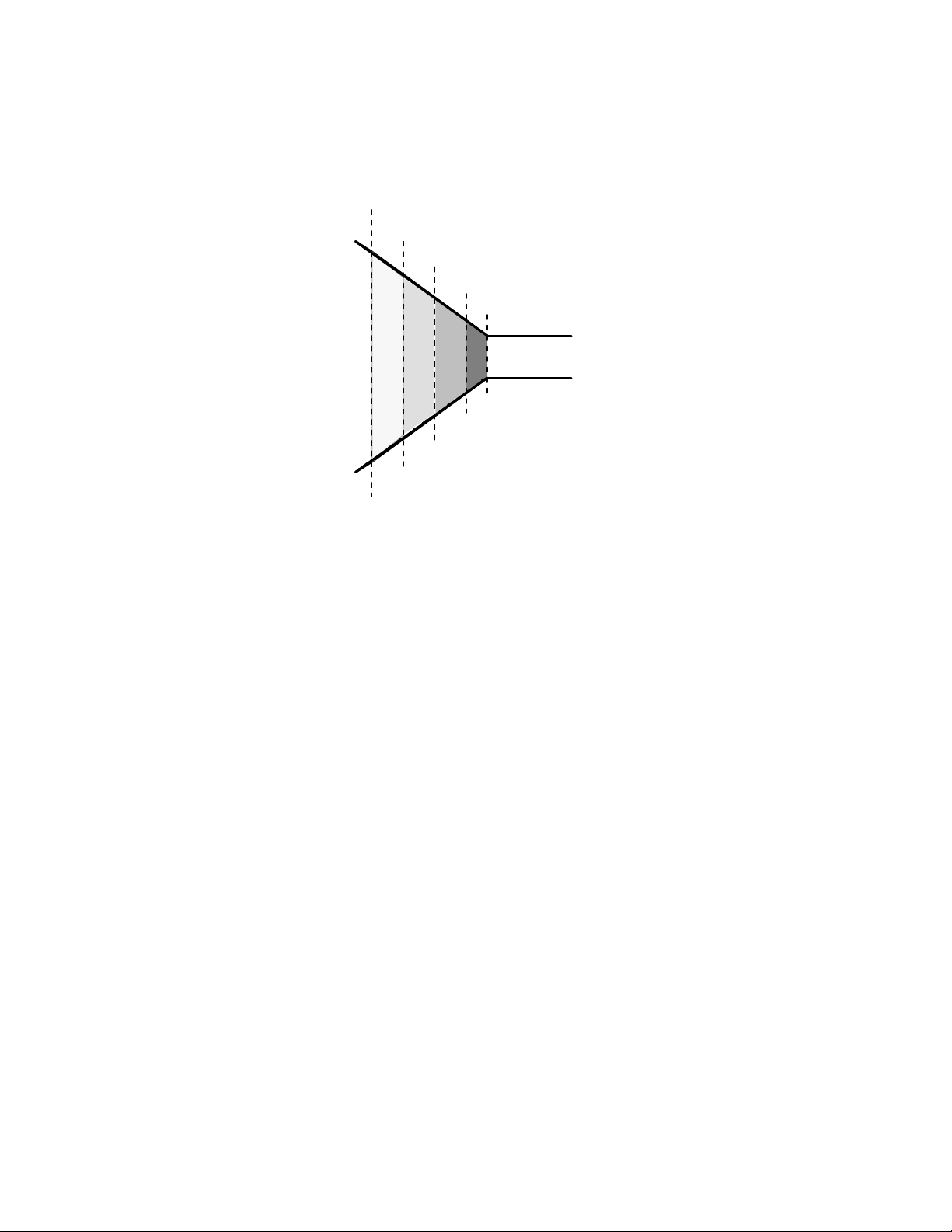
If we were to break down the funnel into sections, we could assign a different function to each area.
Controlled Output Signal
In making use of each function, we could funnel down the dynamic range of the audio signal as it
passes from one area to another.
Wide-Band AGC
Multiband Leveling
Multiband Limiting
Clipping
Dynamic Input Signal
Figure - Audio Processing Funnel Concept
The less aggressive RMS functions, (AGC and Leveling) are assigned to the wider dynamic range
areas. This permits the funnel effect to begin without causing the perception of being affected. As the
dynamic range is reduced, more aggressive peak functions (Limiting and Clipping) can be added to
complete the process, again without the perception of affecting the audio.
From this brief discussion, you may be able to see why the aggressive functions, such as limiting and
clipping, can sound overly aggressive, or even offensive, if used within the wrong stages of a
processing system. Later, we will put this concept to use with respect to making adjusts of the
parameters on the processing system.
Feedforward Control
Vital to the great sound of the Unity AM is our use of feedforward control circuitry in all the
dynamic processing functions, i.e., the Wide Band AGC, Multiband Levelers, and Multiband
Limiters. This enables the processing ratio to remain constant across all levels of processing. By using
feedforward control, the Unity AM will always operate at the same processing ratio, providing a
wider range of operation. This yields improved sonic consistency, regardless of the amount of
processing employed. Feedback systems, found in most other processors, have “sweet spot” windows
that narrow with the changing of ratios as the amount of processing varies. This is why most, if not
all, feedback processors develop a thick, dense, mushy, and unnatural quality to their sound as they
are driven deeper and deeper into gain reduction.
17
Page 18
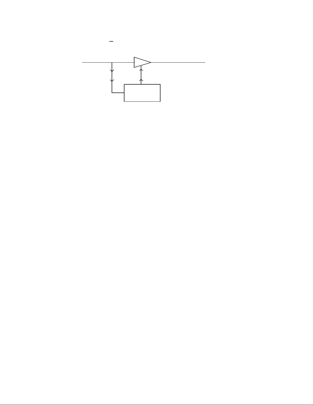
Gain Element
F EEDFORWARD CONTROL
Audio In Audio Out
•
Control Information
CONTROL
CIRCUITS
Figure - Feedforward control circuitry
In feedforward dynamics control, the input audio signal to the gain control circuits is monitored, and
adjusted if necessary, before the gain element. The resulting control information is then “fed forward”
to the element. This produces dB linear gain control at a consistent ratio that remains constant
regardless of the amount of processing is employed.
For example, if the low band leveler is operating with a compression ratio of 4:1, any amount of
control, whether it is 3dB or 23dB, will operate the 4:1 ratio. Because the developed control
information is derived from the input side of the gain element, all corresponding control reaches the
gain element as it happens in real time. As the incoming input audio changes, the gain element is able
to make the same corresponding level adjustment change at the same time.
The gain element in a feedforward control scheme is a “dumb” device. It only does what it is told to
do by the control information and nothing more. If the control circuits are able to develop the correct
information, then the gain element is capable of providing a very natural and smooth effect to the
audio that is available over a wide operating range. If the control circuits develop the wrong
information, i.e. incorrect time or ratios, the gain element will produce an unnatural audio effect. The
Unity AM utilizes feed forward control which aids in creating its natural unprocessed sound.
As you can see from the figure below, when using a feedback gain processing technique the control
circuits develop the control information after the audio has passed through the gain element. The
information is then “fed back” to the element to accomplish gain control. Gain control operates in a
dB log/linear fashion. This changes and increases the processing ratio and continues to do so as more
processing is employed. For example, when 3dB of audio crosses the processing threshold the ratio
may be 3:1, but at 23dB the ratio may have increased to 20:1.
18
Page 19
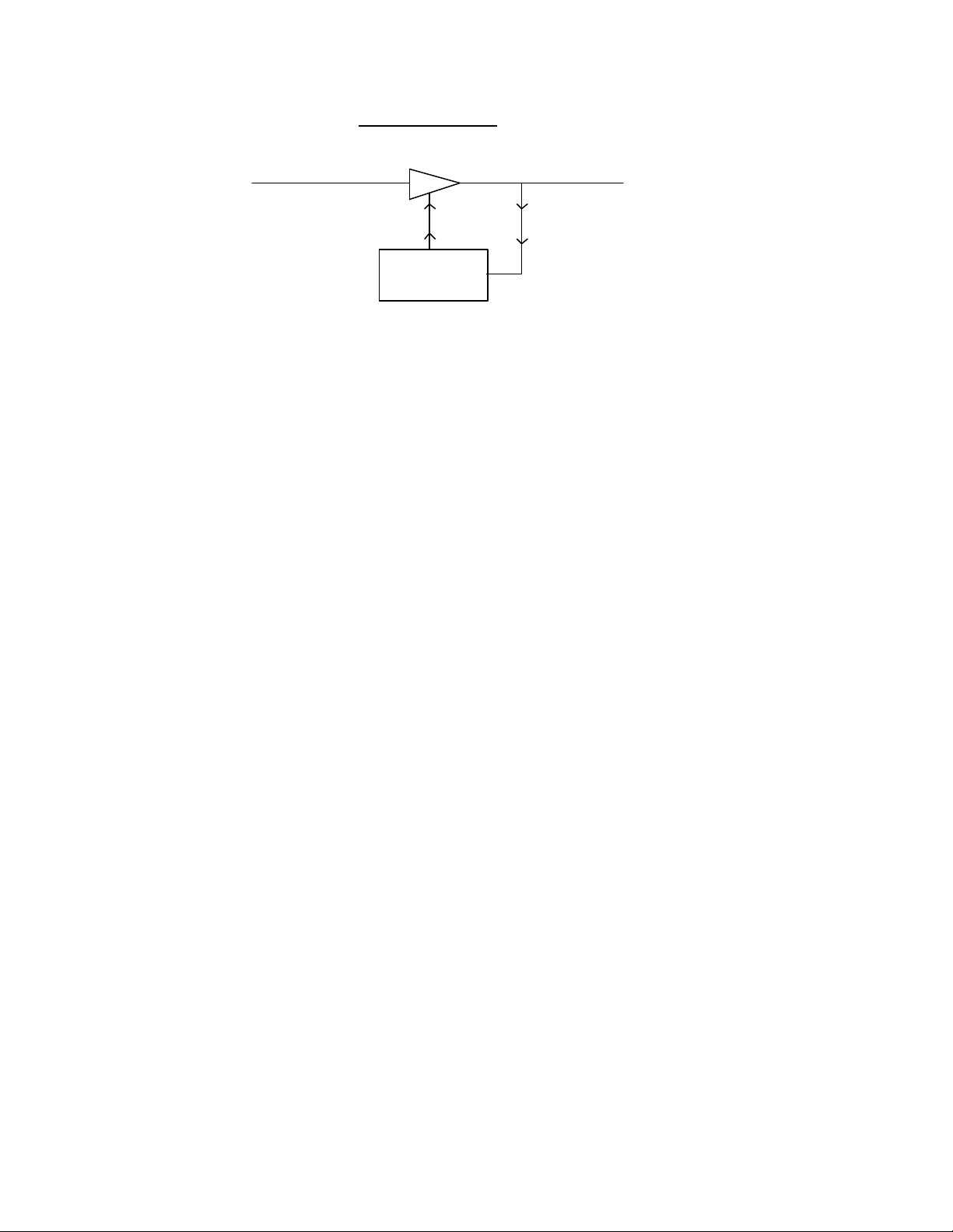
FEEDBACK CONTROL
Gain Element
Audio In Audio Out
Control Information
•
CONTROL
CIRCUITS
Figure - Feedback control circuit
Notice that the gain element is operating within the closed loop of the control circuits. By the time the
control information reaches the gain element, the level that required adjustment has already passed
the point of control. This is especially problematic when transient peak information occurs. The gain
element never really adjusts the leading edge of the peak, leaving the peak to be processed by a
subsequent stage. If a dynamic limiter follows, the limiter should take care of the peak, although the
resultant sound may be perceived as “dense” due to high limiting ratios. If a feedback limiter follows,
that limiter will not be able to control the leading edge of the waveform resulting in added, and
sometimes excessive, clipping of the waveform.
If the audio levels to be adjusted and the control information generated to process that audio vary over
a wide range, the gain element will generate increased intermodulation distortion. This is a key reason
why feedback gain control circuitry yields a “denser” and more fatiguing sound the harder it is driven
with audio level. This explains why these systems always will have a narrow “sweet spot” of
operation that is usually ranges only a few dB.
This discussion may lead you to ask why feedforward control is not more prevalent. The reason is, in
part, to the difficulty in designing the needed control circuits within the true analog domain. In order
for this style of circuit to operate, true dB linear adjustment is necessary and, for this to take place in
analog, log circuits are needed to create the dB linear control. In the past, such analog circuitry
usually was very unstable, cumbersome, and costly and could cause inconsistency within the
processing circuits. Since this dB linear function is performed digitally in the Unity AM, simple,
consistent, and reliable operation is achieved.
Quality versus loudness
The tradeoff between quality and loudness is primarily affected by the use of the limiting and clipping
sections. While either function will generate more “dial presence,” they both offer differing artifacts
and side-effects. With additional use of limiting, intermodulation distortion is increased. The added
dynamic activity of the limiters causes the audio to sound as if it is “overly controlled.” This can be
perceived to the ear as “pumping,” “breathing,” “dense,” or “mushy.” When the clipping is raised,
19
Page 20

harmonic distortion is increased. The audio level is in effect “running into the brick wall.” This may
causes to sound “broken-up,” “torn,” “rough,” or “edgy.” As you might imagine, the harder limiters
and clippers are driven, the louder the perception…and the more likely you have increased
intermodulation and harmonic distortion.
Through the careful use of the multiband Leveler sections, high RMS levels can be created. This will
allow consistently controlled amounts of limiting and clipping to be used without the cost of added
distortion. If increased loudness is the goal, two possible methods should be experimented with. The
first makes use of the multiband Levelers and Limiters. By increasing the output of the multiband
Leveler sections, you are raising the controlled RMS levels to the Limiters. This will build increased
loudness by, in effect, driving the Limiting harder. The second possibility will be to increase the
amount of Clipping. With either of these two options, it is suggested that when making changes, work
with small 5% increments.
Keep an open mind
The Unity AM, is a different kind of processing system. We realize that many of your views on audio
processing are based upon your experiences with products with which you have previously worked.
You may find that the techniques and procedures that you have utilized up until the present, may not
create, perform, or have the same affect with the Unity AM. Because of this, we ask that you proceed
with the installation, setup, and operation with an open mind.
While the Unity AM operates around concepts that are not being utilized in other processing systems,
this is not a reason for you to be concerned. In fact, we have created a whole new realm of
possibilities. Here is a chance for you to master new processing techniques. And whatever your
processing requirements, needs, or desires are, the Unity AM can achieve them.
It would have been easy for us to “repackage” old technologies and stick the word “digital” on the
front panel. Instead, with the Unity AM, we have created something completely new. Once you have
has a chance to use the Unity AM, we know you will appreciate our efforts.
20
Page 21

Installation
Clarifying Your Objectives
Your success in installing and getting the most our of a processing product is, or lack of, will be
directly related to how well you have developed your objectives for the product. With a clear set of
objectives, your tasks will be more clearly defined. Whether you are seeking better overall quality or
specific spectral improvements, try to articulate and write down your goals. Do you want a little more
loudness or “presence” on the dial? Are there certain characteristics of the sound of other stations in
your market that you want to emulate? Are there any you want to avoid? If you are installing the
Unity AM on evaluation, it is equally important to have a list of specific factors you are going to use
to make your comparison.
Engineering, programming, and management should all participate in the development of these
objectives. After all, processing can have a direct effect on the bottom line of your station. A little bit
of agreement before installation can save you a whole lot of disagreement afterwards.
Available time
Let’s get one thing straight: It takes time, a good deal of serious time, to process your station. We
realize in our business today, time is a precious commodity. Our Unity AM, and its competitors, are
expensive and multifaceted. We hate to sound like we are nagging, but don’t try to install the Unity
AM in between other major projects or the week your boss or your assistant is on vacation. Make
certain in advance that the staff members who helped you set your objectives will be available to
consult with you when you adjust the Unity AM.
How much is enough time? Good question! We feel that working with a system for at least a week is
a good starting point. (Look at the clock and see how long it has taken you to read the manual to this
point. And we have not even told you how the turn on the Unity AM!) We don’t suggest that you
drop everything for a solid week. What we do recommend that you install the Unity AM during a
week when you can spend a few hours day on the project.
Installation considerations
Installing the Unity AM requires a bit more than mounting it in the rack, connecting some cables, and
then putting it on the air. (We modestly believe, however, that our processor is the easiest to install in
its class.) Among the factors you should consider are:
1) Monitor Location You should have a good location in which the system, once on the air, can be
21
Page 22

monitored. We suggest a good tuner, with good reception, feeding a set of studio monitor speakers
to be sufficient. While car radio and other “typical listener situation” settings are important, they
should not be the main reference points.
2) Good, Clean Source Material A well respected processing colleague once said, “Garbage in,
produces more garbage out!” He was not kidding. If you are using poor source material, or poor
performing playback equipment, you will not get maximum sonic benefit from your demo.
Anomalies that you perceive to be processing problems, may be source problems that the
processing is exaggerating! Make sure that you start out with a good first step - good source
material!
3) Mic Processing This may appear trivial, but the perceived sound of “live” voices over the air can
change dramatically with different processing systems. Whatever the effect your on-air
microphones will probably change when you change your processing. If you utilize mic
processing, you may have to adjust it to suit the operation of the new processing system. Most
announcers develop a “comfort zone” with respect to the sound of their voice over the air. When
that “comfort zone” is changed or modified, the common response is that something is wrong.
Mic processing can be a very important part of your overall station sound.
4) Operating Levels This is another simple area where trouble can develop. Make sure the input
and output levels of the Unity AM are at the operating at the proper level within your system.
(Did you know that operating a processor with insufficient level into an STL system will cause
loss of modulation and loudness? I only mention it, because we’ve seen it happen more than a
few times!) If you are comparing the Unity AM with another processor, be sure they are both
operating at the same levels. Your modulation monitor is an important tool in any processing
comparison.
Installation checklist
The following checklist will further assist with installation:
1) Finish reading this manual. (Sorry, we could not resist slipping this in one more time.)
2) Quickly revisit your goals and objectives, and decide upon whom is to assist with the evaluation.
3) Mail or fax the initial warranty registration to Cutting Edge. This way we will know who you are
if you call for assistance.
4) Perform the physical installation and initial set up. Start with one of the factory presets.
5) Once on the air, proceed from a processing level similar to that currently used by your station and
then if desired, become more aggressive. This is less likely to draw hasty, and negative, opinions.
22
Page 23

6) Listen for awhile, then adjust. Try to avoid the temptation to “fiddle” with adjustments, moments
after getting the system on the air. Remember you should evaluate the operation over time, not
moment to moment! When it is time to adjust, the provided worksheets that can assist in
establishing improved settings of operation.
7) In making changes to the system, do not make hasty or radical changes. Also, do not make
too many different adjustments all at once. If too many parameters are changed at one time, it
is hard to determine which change made the difference. That can be frustrating whether the
change made you station sound better or worse!
8) A procedure we have found successful is the “sleep on it” method. Spend time adjusting and then
listening, and when the system gets to a point where it sounds good, stop for the day. In making
changes, there does come a time when the ears become less and less sensitive to adjustments
performed. The ears sort of “burn out.” That is why spreading the adjustment period over a
number of days is recommended. If it still sounds good after you have “slept on it,” quit
adjusting. If it does not, continue with this method until you’re satisfied. If the procedure is
working, you will find that each day the discrepancies are smaller and you’re making fewer
adjustments.
9) When you get it where you like it, STOP! Nothing more said!
10) Send in the second registration card. Now we know who you are an how you are using the Unity
AM.
A Word About Relative Phase
If the relative phase relationship of this system is different to your existing system, or the system you
are comparing it too, it could cause your announcers to sound “weird” in their headphones. If this
happens, then the relative phase of the Unity AM is 180 degrees different than what your announcers
are used to. To remedy this, just reverse the polarity to both of the inputs on the Unity AM.
Mounting and connections
Before rack mounting the Unity AM, review all items in this section. Some require that you change
jumpers on the cards located inside the unit and we know you will say nasty things about us if we
didn’t warn you.
We recommend installing the Unity AM with at least one rack height of space open above the unit.
This will enhance ventilation and prolong component life.
Setting pre-emphasis
For AM broadcasting worldwide, some form of pre-emphasis boost is employed. Generally it is 50µs
23
Page 24

or 75µs. For North and South America, the modified 75µs NRSC standard is used. The NRSC
standard provides a 10dB boost at 10 kHz. A shelving response for frequencies above 10kHz, along
with a tight 10kHz low pass filter, is employed to control out of band emissions.
The factory default pre-emphasis setting in the Unity AM is the modified 75µs NRSC standard. The
pre-emphasis can be changed will relative ease.
Before going on to the next step, be aware sophisticated microprocessor controlled products like the
Unity AM do not like to be zapped by static electricity. Please take all required precautions to create
a static free environment before opening the Unity AM.
To change the pre-emphasis, locate and remove card #8, the eighth card from to the right of the power
supply, and set the “berg” jumpers according to the diagrams that follow:
24
Page 25
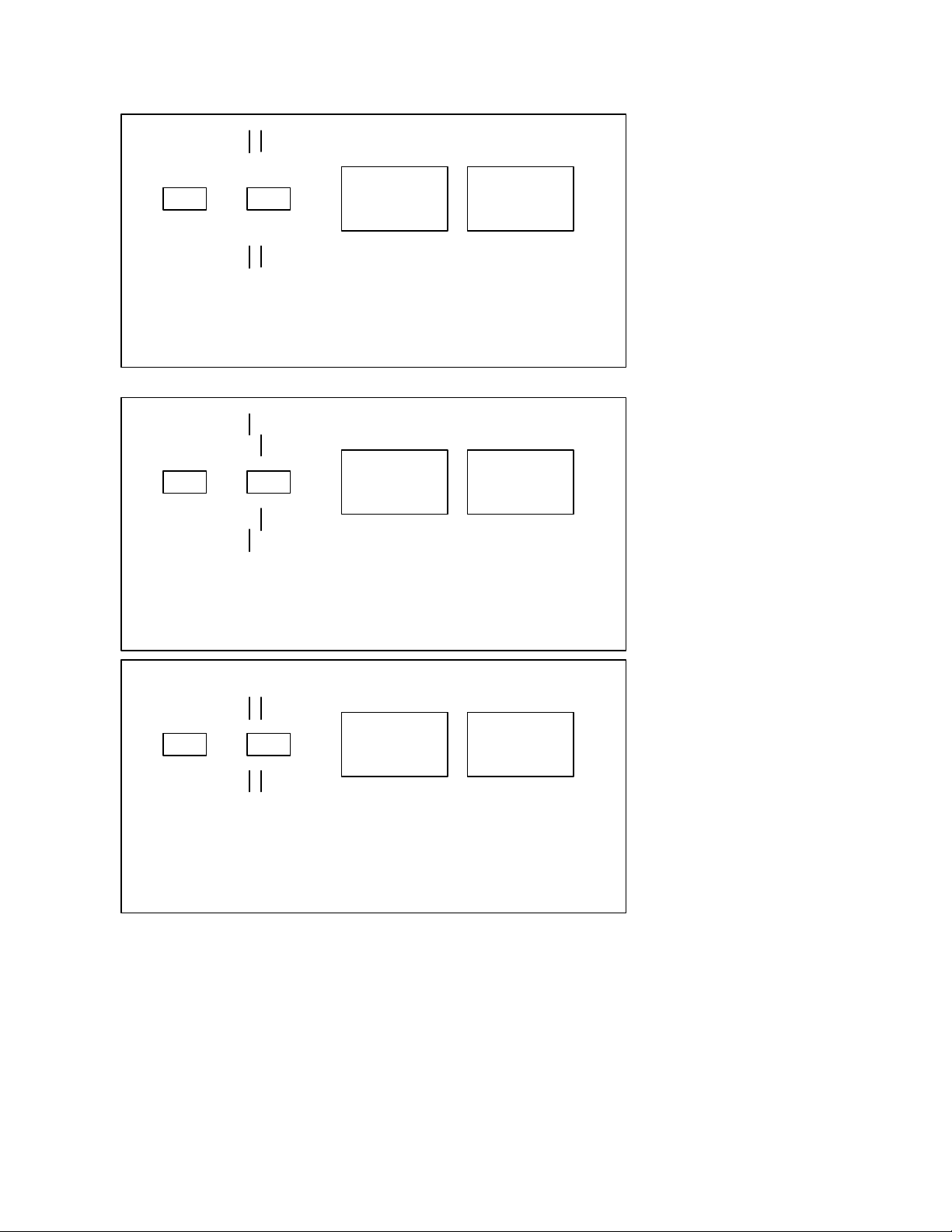
x x
x x
x x
x x
x x
x x
x x
x x
x x
x x
x x
x x
NO PRE-EMPHASSIS
50 us PRE-EMPHASSIS
x x
x x
x x
x x
x x
x x
75 us PRE-EMPHASSIS
Rear Panel Connections
AC connection
AC power is applied to the EIC style connector. The Unity AM will operate from 100 to 240VAC.
Voltage selection is made using the jumper located in the fuse compartment of the AC connector
assembly. The default voltage shipped by the factory is 120VAC. We may have changed the
operating power setting at your request before shipping the unit.
25
Page 26

Always turn the Unity AM off and disconnect the power cord before attempting to replace the fuse or
change the operating voltage. Always replace the fuse compartment before applying power to the
unit.
To access the fuse compartment, insert a small screwdriver into the tab just below the power
connector and pull the fuse compartment gently towards you. Grab the compartment on both sides to
remove it. Slide out the small circuit card with the jumper on it. Locate, on the top of the board, the
voltage to which you want to set the Unity AM. Orient the jumper so that it points in the direction
opposite that label. Insert the board with the side indicating the proper voltage first so that the jumper
sticks out towards you. Replace the fuse compartment and check that the jumper is displaying the
operating voltage you need. To change the operating voltage, locate the white jumper at the bottom of
the compartment.
When changing the operating voltage to 220 or 240VAC, change the fuse value to .200 amps.
Audio input
Before connecting audio to the Unity AM, you need to choose either -10dB or +4dB as your input
operating level. The factory default setting is +4dB. If you want the input sensitivity to be configured
for an input level of -10dB, you will need to change some “berg” jumpers on the input board.
Before going on to the next step, be aware sophisticated microprocessor controlled products like the
Unity AM do not like to be zapped by static electricity. Please take all required precautions to create
a static free environment before opening the Unity AM.
To change the operating levels, remove the cover. Lift out Card 2, the second board from the left hand
side. With the board facing you and the connectors facing down, you will notice two “berg” jumpers
to the left side. They are located near U101 and are labeled J101 and J102. The “berg” jumpers are
mark for either +4dB or -10dB input level. To change the input level sensitivity, move the jumper
from the +4dB to -10dB position.
Connect the input audio to the female XLR jacks on the back. The input circuitry is active balanced,
pin #2 high, pin #3 low, and pin #1 ground. Make sure to connect accordingly. If unbalanced, make
sure to use pin #2 as high, and tie pin #3 to the system ground. Ground loop “hum” can develop if this
is not done.
26
Page 27

Discrete Left/Right Audio Outputs and De-emphasis Selection
Individual Left and Right channel outputs are available on the male XLR jacks. This signal is the
output of the final processing function of the system, the Clipper/Low Pass Filter. The output circuitry
is active balanced, pin #2 high, pin #3 low, and pin #1 ground. Make sure that pin #2 is connected to
the “+” terminal of the audio input on the transmitter. If not, incorrect modulation polarity can result.
It is important in AM broadcasting to observe correct output polarity. Since the Unity AM is capable
of modulating asymmetrically , incorrect polarity, coupled with asymmetrical operation, could
actually cost modulation. This would occur by modulating the asymmetrical waveform in the negative
direction. Thus yielding positive modulation of about 80%, having an adverse affect on signal
coverage.
Under normal circumstances the output signal is pre-emphasized, but through jumpers, located on the
motherboard, the signal can be de-emphasized for installations that require a “flat” response as would
be the case when feeding land lines.
It should be noted that through the system jumpers, two different “flat” response audio conditions
could be created. The first, is when no pre-emphasis or de-emphasis is used. Passing the audio signal
through the system without any specified boost and complimentary cut to the high frequencies. The
second, is when a specific amount of pre-emphasis is utilized to boost the high frequencies, and then
the corresponding de-emphasis is used to reduce to the high frequencies to an “overall” flat response.
If there are two options, what are the differences, and why use them? Good question! In the first
instance, there is never any boost to the high frequencies. Because of this, any subsequent preemphasis boost employed AFTER the Unity AM will cause unwanted overshoots in the signal. This
occurs because there is not any final limiting control that follows the pre-emphasis curve that is used
AFTER the processing of the UNITY. These overshoots cause “lost” modulation because their
amplitude must be accounted for in the total modulation of the system.
The second option, where pre-emphasis and de-emphasis is used, makes use of the final limiting
system within the Unity’s processing structure. Since this follows whatever pre-emphasis has been
selected, tight control of the high frequencies is accomplished. Even though the signal is subsequently
de-emphasized, any post pre-emphasis that will then be employed will only boost the high
frequencies to the already previously controlled level. This will allow the system, as a whole, to
modulate with relatively low, or no overshoots.
When, or where is either of these options applied? The answer is determined by what type of system
follows the Unity AM. If any portion of the following system does not employ ANY form of preemphasis, then the first option can be used. Applications might be: final limiting before power
amplifiers, final mixing, and final limiting for mastering purposes.
27
Page 28
The second option must be used in any application that will utilize sort form of emphasis. This would
include: broadcast applications where land lines or some form of STL must be connected to a second
party stereo coder/modulator that will provide pre-emphasis. Any satellite uplink or digital converter
that uses an emphasis technique for improved S/N ratio.
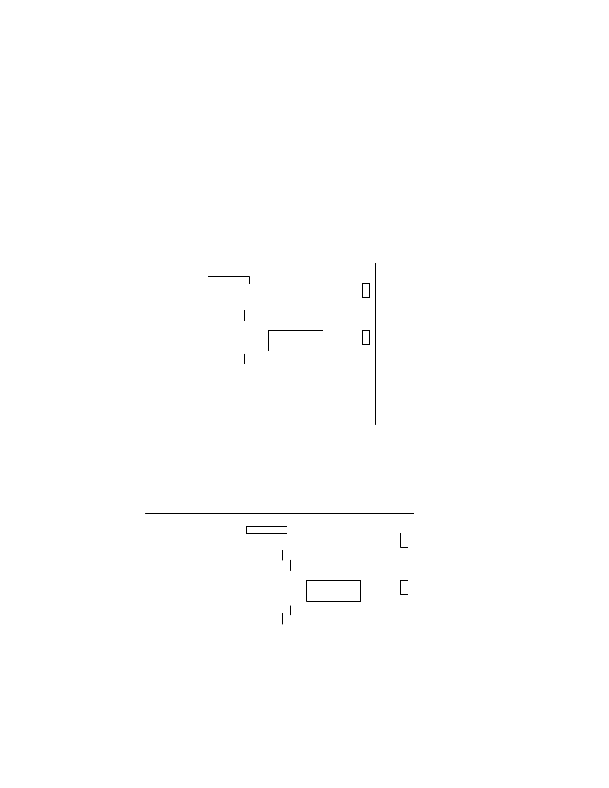
Setting De-emphasis
The jumpers for the de-emphasis options are located in the upper right-hand corner of the
Motherboard. If you are facing the unit, it would be the area to the right, in the rear. Position the
jumpers as described in the following diagrams for the desired de-emphasis.
UNITY MOTHERBOARD
CONNECTOR
JUMPERS
JUMPERS
X X
X X
X X
AD 713
X X
X X
X X
NO DEEMPHASSIS
UNITY MOTHERBOARD
CONNECTOR
JUMPERS
X X
X X
X X
JUMPERS
AD 713
X X
X X
X X
NRSC DEEMPHASSIS
28
Page 29

Matrix Processing Option (For Stereo Only)
For some AM Stereo broadcast applications, it is desirable to setup the processing to operate in a
matrixed L+R/L-R configuration. Accomplishing this is as easy as changing two jumpers on circuit
board #2 inside the Unity AM. Refer to the following diagram for jumper placement. Once this option
is activated, the outputs of the system will provide L+R and L-R signals. The L+R output will be
present out of the Left output connector, and L-R will appear on the Right output connector.
L+R
L
x x x
L-R
R
x x x
Diagram showing matrix jumpers
Interface Port
There are two selectable patch points accessed through the Interface Port connector that will allow
ancillary audio equipment, if desired, to be inserted. You may want to insert reverb, stereo
enhancement, or whatever else you require. One port is located just after the Wide Band AGC and the
other is between the Processor/Leveler and Limiter.
Should you choose to install ancillary equipment through the interface ports, we recommend that you
first complete total installation of the Unity AM without the external device(s). This will allow you to
set audio and processing levels that you can then maintain after adding your extra component.
The DB-25 connector labeled Interface Port provides you with a stereo balanced output from the
Wide Band AGC section and balanced input to the Processor/Leveler and a stereo balanced output
from the Leveler section and balanced input to the Limiter. The connector pins are as follows:
Patch Point #1 Patch Point #2
Pin - 1: WB AGC Left Out (+) Pin - 10 : Leveler Left Out (+)
Pin - 2: WB AGC Left Out (-) Pin - 11: Leveler Left Out (-)
Pin - 3: WB AGC Right Out (+) Pin - 12: Leveler Right Out (+)
Pin - 4: WB AGC Right Out (-) Pin - 13: Leveler Right Out (-)
Pin - 5: Leveler Right In (+) Pin - 22: Limiter Right In (+)
Pin - 6: Leveler Right In (-) Pin - 23: Limiter Right In (-)
Pin - 7: Leveler Left In (+) Pin - 24: Limiter Left In (+)
Pin - 8: Leveler Left In (-) Pin - 25: Limiter Left In (-)
29
Page 30

Pin - 18: Ground
Pin - 19: Ground
Pin - 20: Ground
Use this connector to wire to and from the Unity AM. The outputs are approximately +4dBm and the
inputs will accept a +4dBm level as well. The outputs of the Interface ports are fixed so level
adjustments will have to be made from your ancillary device. The return input level of the first patch
point is fixed. The input level of the second patch point may be adjusted.
First patch point
To connect your ancillary equipment between the Wide Band AGC and the Processor/Leveler, you
should first make note of the processing levels of the Levelers. This is important as you will need this
information to restore the processing levels after installation of your ancillary equipment.
Next, you will need to create a cable. Use the pins for the Wide Band AGC outputs and Leveler
inputs to connect to your devices inputs and outputs directly. (Don’t forget the ground connection.) If
your external device has an unbalanced input or output, be certain to tie the low (-) pin to ground.
The patch point is activated by moving two jumpers located on the motherboard. With the top
removed, locate the two berg jumpers between circuit boards #2 and #3. Both jumpers are capable of
only two positions. Move both jumpers to the alternative position. Patch point #1 is now activated.
When you do your processing set up, be sure to review the instructions for setting the return level
from you external device to the Processor/Leveler inputs. Set the output level of the ancillary device
to provide unity gain. This will insure that the same amount of audio drive is provided to the
multiband processors. If the output gain of the ancillary device is too high, the multiband processors
can be overdriven. This could result in the audio sounding too processed.
Second patch point
Under normal operating conditions, each Leveler band feeds its own limiter band directly and the
Unity AM operates with only one crossover network. When the second patch point on the Interface
Port is used, the wide band audio that is returned to the Unity AM must be band split again. We have
accommodated this by providing an additional crossover network on the limiter circuit board. The
crossover points will exactly mirror those that you will chose in the Leveler section a few chapters
from now when we finally let you play with the processing parameters. To activate this second
crossover network, which you must do when you use the second patch point on the Interface Port, you
must change some jumpers on the limiter board.
Before going on to the next step, be aware sophisticated microprocessor controlled products like the
Unity AM do not like to be zapped by static electricity. Please take all required precautions to create
a static free environment before opening the Unity AM.
30
Page 31

To access the jumpers, start by removing the Unity AM from service and removing the cover. Lift out
Card 6, the sixth circuit board from the left. You will notice eight “berg” jumpers located to the left of
the board. Just change the position of each jumper and replace the board. You have now added the
additional crossover network.
If you are worrying about the addition of this network, just think for a moment how many different
band splitting networks you were using in your old processing chain before the Unity AM! You may
find that, even with two networks in the Unity AM, you have fewer than you had before!
Put the cover back on the Unity AM and place it back into service. When you do you processing set
up, be sure to review the instructions for setting the return level from your external device to the
Limiter inputs.
Serial Communication Port
RS-232, RS-422, and RS-485 serial communication is available at the Serial Port. Using a wiring
configuration that will allow compatibility of the three communications protocols, the Unity AM can
be remote accessed by either a null modem, single line modem, or even a network modem.
The wiring for the DB-9 Serial Port is as follows:
Pin - 2: RS-232/RS-485 RCV (-)
Pin - 3: RS-232 TX (-)
Pin - 4: DTR
Pin - 5: Ground
Pin - 7: RS-485 RCV (+)
Pin - 8: RS-485 TX (+)
31
Page 32

Operation
STATUS SECTIO
N
The obvious
When all connections are made and your Unity AM is sitting in the rack, you are ready for good stuff.
(We assume you have turned the unit on from the switch at the top of the AC input.)
On power up, the Unity AM will read UNITY AM on the LCD screen. We will refer to this as the
Home Screen. You will notice some activity on the Leveler meters that fades after about 10 seconds.
This is normal.
The LCD display
On all screens, other than the Home Screen, the LCD display is divided into the Status Section and
the Menus and Parameters Section. These two areas are divided by a solid line located about onequarter of the way down from the top of the screen.
CURRENT PRESET
MENU LEVEL
DAY DATE TIME
ACCESS LEVELINDICATOR
MENUS & PARAMETERS
LAYOUT OF LCD SCREEN
Figure-Layout of LCD Screen
The Status Section provides current status of certain system functions:
CURRENT PRESET indicates the processing preset currently active
MENU LEVEL indicates where you are in a particular menu hierarchy
DAY OF WEEK, DATE, TIME
ACCESS LEVEL indicates the security level currently active
MODIFIED PARAMETER INDICATOR will appear when a processing parameters have been
modified and but have not yet been stored as a preset
All of this information is found within the top two lines of the screen. The Status Section displays the
same information regardless of where you are in the menu system. If the day of week, date, and time
are not on the display, it is because the internal clock of your Unity AM has not yet been set. We will
do this shortly.
32
Page 33

In the Menus and Parameters Section, information is displayed that show you where you are in the
menu system and, when you are at the appropriate level, the status of particular functions and
features.
The jog wheel and buttons
The jog wheel and buttons combine to make the Unity AM intuitive and easy to operate.
The six Main Menu buttons on the far right of the unit bring you to the primary Unity AM menus.
This makes it easy to you to go quickly to the processing section or features upon which you want to
operate. These buttons are also used for password entry.
The jog wheel is used for several purposes. When in a menu or sub-menu is displayed, turn the jog
wheel counter-clockwise to go down the menu and clockwise to go up the menu. When a variable
function is displayed, the jog wheel is used to adjust that function.
The Select buttons are used to navigate lists of processing functions or features, which represent the
lowest level in the menu system. Use the top Select Up button to move either up a list or to the right
along a list and the lower Select Down button to move either down a list or to the left along a list.
The Enter button is used to store your settings. The Escape button moves you up the menu system
one step at a time until you reach the Home Screen. The Escape button can be of great help when you
are not certain to where in the menu system you have navigated. Just a few presses on the button and
you are back to the Home Screen.
Security
Password Security Levels
A this point you may be getting a little impatient. You’ve been reading this manual for a long time
and you have yet to run audio through the Unity AM. Hang in there, because we will get to the good
stuff in just a few more sections.
Before you can get started, you must establish a Password Security Level that grants you access to
programming the Unity AM. Upon initial power up, the Unity AM is set to the factory default,
Password Security Level 0. This is indicated in the Status Section of the LCD display by a L:0. This
security level does not allow access to any of the functions except the Passwords sub-menu displayed
when the Other Menu is selected by pushing the Other button. So please, do not panic if you are
pushing other buttons with no results.
The Unity AM provides four levels of security, ranging from absolutely no access to any of the
processing adjustments and parameters to full access to all functions. These four levels are indicated
in the Status Section of the LCD screen by L:0 , L:1, L:2, and L:3.
33
Page 34

Level 0 is the total “lockout” level. Level 0 provides no access to all processing functions. (That is
why we gave it the number zero.) The only menu that can be accessed is the Passwords sub-menu of
the Other Menu. This level also has no password code to access it.
Level 1 permits all processing parameters to be viewed but not adjusted. In addition, the Serial
Communications port and the LCD screen functions can be adjusted. When changing to this level, the
factory default code is: 1 2 3.
Level 2 provides the same access as Level 1, but with additional access to the Preset List and the
Day-part List in the Other Menu. This level is designed for a Program Director, because it allows him
or her to make processing changes based on preset parameters and to make scheduling changes. When
changing to this level, the factory default is: 2 3 4.
Level 3 grants full access. All functions and parameters can be monitored and adjusted from this
level. Once this level is selected, be careful because you can make a good mess of things. When
changing to this level, the factory default is: 3 2 1.
To permit you to change Password Security Levels rapidly, you enter password numbers using the
Main Menu buttons. For the purpose of entering passwords, use the top button for “1,” the next button
for “2,” and so on down the row.
Changing Password Security Levels
The first time you power-up your Unity AM, the Password Security Level will be set to 0. To access
the Change Password Sub-menu, press the Enter button. Next to the text, NEW LEVEL, the number 0
will appear, reverse highlighted, in a box on the screen.
The number will match the current Password Security Level indicated in the Status Section of the
LCD display. Use the jog wheel to change to the desired level. If you are performing initial setup,
scroll to Level 3. Push the Enter button.
The words Enter Password appear with a blinking cursor. Use the Main Menu buttons to enter default
password 3 2 1 by pressing the third, second, and first (Clipping, Limiter, and Leveler) Main Menu
buttons one at a time in the indicated order. Press the Enter button. The level indicated in the Status
Section of the LCD display should now be 3 and you will see a message that reads PASSWORD
CORRECT. LEVEL CHANGED. You will have full access. Press the Enter button to return to the
Home Screen.
The procedure above can be used to quickly change Password Security Levels from the Home Screen.
You may alternately use the menu system to change the Password Security Levels. Start by pressing
the Other button to show the Other Menu in the Menus and Parameters Section of the LCD display.(If
34
Page 35

you are not at the Home Screen, press the Escape button until you are.) A list of sub-menus will
appear. Turn the jog wheel until the Systems Options Sub-menu is highlighted. When it is, press the
Enter button and you will now see the sub-menu.
From the Systems Options Sub-menu, locate the Passwords Sub-menu and turn the jog wheel until it
is highlighted. Press the Enter button and you will see the Passwords Sub-menu
From the Passwords Sub-menu, locate the CHANGE LEVEL function and turn the jog wheel until it
is highlighted. Press the Enter button.
Now, next to the text, NEW LEVEL, the number of the current Password Security Level will appear,
reverse highlighted, in a box on the screen. The number will match the current Password Security
Level indicated in the Status Section of the LCD display. Use the jog wheel to change to the desired
level. Push the Enter button. The Password Security Level can be changed to a more secure setting
without a password. (For example, when going from level 3 to level 1.) If you are going to a more
secure level, the words LEVEL CHANGED will appear. Press the Enter button to return to the Home
Screen.
When changing to a higher, less secure setting, a password is required. The words Enter Password
appear with a blinking cursor. Use the Main Menu buttons to enter default password 3 4 5 by pressing
the third, fourth, and fifth (Clipping, Stereo Generator, and Composite Clipper) Main Menu buttons
one at a time in the indicated order. Press the Enter button. The level indicated in the Status Section of
the LCD display should now be 3 and you will see a message that reads PASSWORD CORRECT.
LEVEL CHANGED. You will have full access. Press the Enter button to return to the Home Screen.
Changing passwords
The passwords to levels 1, 2, and 3 can be changed to any custom password that you desire.
Passwords may be up to five digits and use the numbers 1, 2, 3, and 4 corresponding to the Main
Menu buttons.
If you are not in the Passwords Sub-menu, navigate to that sub-menu. From the Home Screen, start by
pressing the Other button to show the Other Menu in the Menus and Parameters Section of the LCD
display.(If you are not at the Home Screen, press the Escape button until you are.) A list of sub-menus
will appear. Turn the jog wheel until the Systems Options Sub-menu is highlighted. When it is, press
the Enter button and you will now see the sub-menu.
From the Systems Options Sub-menu, locate the Passwords Sub-menu and turn the jog wheel until it
is highlighted. Press the Enter button and you will see the Passwords Sub-menu. Locate the
CHANGE PASSWORD function and turn the jog wheel until it is highlighted. Press the Enter button.
Now a number should appear, reverse highlighted, in a box on the screen. The number will match the
current Password Security Level indicated in the Status Section. Use the jog wheel to choose the level
35
Page 36

whose password you want to change. Push the Enter button.
As a security measure, you will be asked to enter your old password, which can be accomplished by
using the Main Menu buttons. You will then be prompted to enter your new password, which again is
accomplished with the Main Menu buttons. You will be prompted again, this time to confirm your
new password by entering it again. This helps prevent your entering a wrong password accidentally.
The screen will now display PASSWORD HAS BEEN CHANGED.
When you are finished, press the Escape button twice to return to the Home Screen.
Notes on passwords
Passwords only provide security if you use them. Distribute passwords only to station personnel only
when they must have access to Unity AM functions. Instruct everyone with a password to return the
Unity AM to Level 0 after they have finished working with it so that it is again in its most secure
state.
If you change your passwords and forget them, you have a significant, but not impossible problem.
You can restore the Unity AM to factory defaults using a Hardware Initialization function. In doing
so, you will erase all of your custom programming and processing settings. And we mean all of
your custom programming! Hours and hours of processing decisions could be lost forever if you do
not have a backup copy of your settings. Remember, this is a consequence of losing your password.
Hardware Initialization should only be used as a last resort.
Before going on to the next step, be aware sophisticated microprocessor controlled products like the
Unity AM do not like to be zapped by static electricity. Please take all required precautions to create
a static free environment before opening the Unity AM.
To accomplish Hardware Initialization, you will have to take the Unity AM out of service, turn off the
power, and remove the top cover of the unit. Locate Card 1, the Micro-Controller, which is the first
board to right of the Power Supply or the left-most board in the chassis. Located about mid-board and
to the rear of the is a jumper. Change the jumper to the other position and replace the card. Turn the
Unity AM on, wait 15 seconds, and turn it off again. The Unity AM has re-initialized itself with all
the factory defaults in place. Again remove Card 1, and restore the jumper to its original position. If
you fail to take this last step, the unit will initialize every time it powers up! The Unity AM may
now be reinstalled.
36
Page 37

The Real Time Clock
For the Unity AM to be able to schedule processing events, the Real Time Clock must be set. The
format of the clock, which is displayed in the Status Section of the LCD display is the day of the
week, date, and time of day. The day of the week is represented by a two letter designation: SU for
Sunday, MO for Monday, TU for Tuesday, WE for Wednesday, TH for Thursday, and SA for
Saturday. The date is represented in a month/day/year format common in the United States. We hope
that users in other countries who use a different date format will forgive us for this preference.
Time of day is represented with a 24 hour notation from 0:00:00 to 23:58:59. For those used to using
the AM and PM connotations, note that the hours from midnight to just before high noon are
indicated as 0:00:00 to 11:59:59 and the hours from high noon to midnight are indicated as 12:00:00
by 23:59:59. As an example, 9:15 AM would be indicated as 9:15:00, whereas 9:15 PM would be
indicated as: 21:15:00.
Setting the Clock
To set the Real Time Clock, start at the Home Screen, press the Other button to show the Other Menu
in the Menus and Parameters Section of the LCD display. (If you are not at the Home Screen, press
the Escape button until you are.) A list of sub-menus will appear. Turn the jog wheel until the
Systems Options Sub-menu is highlighted. When it is, press the Enter button and you will now see the
sub-menu.
From the Systems Options Sub-menu, locate the Clock Sub-menu and turn the jog wheel until it is
highlighted. Press the Enter button and you will see the Clock Sub-menu
From the Clock Sub-menu, locate the Set Clock function and turn the jog wheel until it is highlighted.
Press the Enter button.
The current Real Time Clock setting will appear in the format will appear in showing the date, and
time of day. (For example, it may read as follows: 4/21/93 14:34:43. Notice that the number
designating the month is reverse highlighted showing that you may now use it. Turn the jog wheel
until the month is correct and press the Select Up button. Now the day portion is reverse highlighted.
Turn the jog wheel until the day is correct and press the Select Up button. Now the year portion is
reverse highlighted. Turn the jog wheel until the year is correct and press the Select Up button.
Continue using the same procedure to correctly set the hour, minutes and seconds. At any time, you
can go back to correct a previous setting by pushing the Select Up (to move right) or Select Down(to
move left) buttons. When you have finished setting the seconds, press the Enter button. The Real
Time Clock has now been entered into the system and will appear in the upper right-hand corner of
the Status Section of the LCD display. Any changes that need to be made to the Real Time Clock are
performed using the procedure detailed above. Press the Escape button three times to return to the
Home Screen if you like.
37
Page 38

Daylight Savings Time (Summer Time)
The Real Time Clock of the Unity AM has the ability to recognize and automatically adjust to
Daylight Savings Time. (Daylight Savings Time is called Summer Time in some countries.) This is
an optional function as not everyone uses Daylight Savings Time. This function will set the Real
Time Clock ahead one hour at the time and date you select as the start of Daylight Savings Time and
will set the Real Time Clock back one hour at the time and date you select as the end of Daylight
Savings Time. If Daylight Savings or Summer Time is not required, you may skip this section as the
factory default for this feature is off.
We will use Daylight Savings Time start and ending dates for the United States as an example. In the
US, Daylight Savings time begins on the first Sunday of April, and ends on the last Sunday of
October. (If Daylight Savings or Summer Time is different in your country, use the same procedure
substituting the times and dates appropriate to your country.)
For the purpose programming Daylight Savings Time, think of Sunday as the first day of the week.
Using our US example, we will program the Unity AM to turn on Daylight Savings Time on the first
day (Sunday) in the first week during April and restore standard time on the first day (Sunday) in the
fifth week during October. Our programming format should set Daylight Savings Time correctly
every year without your having to take any action. (We cannot guarantee that in a certain year,
however, the rules for the start and end dates or Daylight Savings Time will not change in your
locality.). In the event that the daylight savings format be changed, or different, we have also
provided access to the programming function so that it can be modified.
To turn on and set the Daylight Savings Time feature, you should be in the Clock Sub-menu. If you
are not in the Clock Sub-menu, start at the Home Screen, press the Other button to show the Other
Menu in the Menus and Parameters Section of the LCD display.(If you are not at the Home Screen,
press the Escape button until you are.) A list of sub-menus will appear. Turn the jog wheel until the
Systems Options Sub-menu is highlighted. When it is, press the Enter button and you will now see the
sub-menu.
From the Systems Options Sub-menu, locate the Clock Sub-menu and turn the jog wheel until it is
highlighted. Press the Enter button and you will see the Clock Sub-menu. From the Clock Sub-menu,
locate the Daylight Savings function and turn the jog wheel until it is highlighted. Press the Enter
button to toggle the function On and Off until it is set the way you want it.
To set the start and end of Daylight Savings Time, use the jog wheel to scroll to Start Date/Time, and
press the Enter button. The first number, designating the week of the month is highlighted. For
example, if a 1 is displayed, it indicates that the first week of the month will be programmed. To
change week of the month, turn the jog wheel until the week of the month you want is displayed.
Now press the Select Up button. The day of the week indicator is now highlighted. For example, if a 1
is displayed, it indicates that the first day of the week (Sunday) will be programmed. To change the
38
Page 39

day of the week, turn the jog wheel until the day of the week you want is displayed. Now press the
Select Up button.
The month indicator is now highlighted. For example, if a 4 is displayed, it indicates that the fourth
month (April) will be programmed. To change month, turn the jog wheel until the month you want is
displayed. Now press the Select Up button.
Continue using the same procedure to correctly set the hour, minutes and seconds you want Daylight
Savings Time to start. At any time, you can go back to correct a previous setting by pushing the
Select Up (to move right) or Select Down(to move left) buttons. When you have finished setting the
seconds, press the Enter button. This sets or modifies the Start Date/Time. To set the End Date/Time,
use the jog wheel to scroll to End Date/Time and use the same procedure to set this function.
Orientation to the Main Menus
Imagine each of the Main Menu buttons as the key to opening the door or each processing function.
Press the Leveler button. You should now see a number of menu choices on the screen. These are all
the functions of the Leveler that are available to you. We will get into these in more detail in just a
few moments. You can switch from a Main Menu to another by just pushing a Main Menu button.
You may also move from a sub-menu to a Main Menu by pressing a Main Menu button a few times
until the desired Main Menu appears.
Let’s move from the Leveler Main Menu. The Unity AM saves you steps by allowing you to navigate
directly between any two Main Menus. Press the Clipping button. We are now looking at the Main
Menu choices for the Clipper. Notice that we did not have to step back to the Home Screen to move
between Main Menus. However, you can use the Escape button to return to the Home Screen any
time you like. Try it now.
The Escape button will always “raise” your operation one level of menu choices. You will find the
Escape button to be very handy and utilized often.
Setting the Unity AM input levels
To further our tour of operation, let’s select and operate a function. All Unity AM units are shipped
with the input levels set at 50%. We can start by adjusting the input audio levels.
Select the Leveler Main Menu by pressing the Leveler button. The top sub-menu is the Input Levels
Sub-menu. If the Input Levels Sub-menu is not highlighted, turn the jog wheel until it is. Press the
Enter button.
Notice two choices, Left Input and Right Input, each with a numeric bar graph next to it. The numbers
next to the menu choices represent the percent of the input range you have used from 0% to 100%.
39
Page 40

(All Unity AM menu choices with range adjustments use percentages, except in the Crossover Submenu where frequency values are used )
The Left Input should be highlighted. If it is not, press one of the Select buttons until it is highlighted.
This indicates that the left channel input level can now be adjusted. By rotating the jog wheel under
the LCD screen, the input level can be adjusted. To adjust the Right Input press one of the Select
buttons to highlight the Right Input Adjustment of the right channel audio level can now be
accomplished. After adjusting, the input levels, press the Enter button to store the adjustments within
the system. If you do not press the Enter button, the settings will default back to the previous
settings. Please make note of this requirement, as it affects any menu choice that requires
setting an operating range.
To set your input levels correctly, we will use the Input Level located on the far left of the Processing
Display.
Run a typical audio source into your Unity AM. As you adjust the input levels up and down using the
jog wheel, you will observe the Input Level Meters are multicolored. At higher inputs, the level
meters will show red at the top of the scale. Proper input levels for the Unity AM should have the first
and second red meter indicators light on peaks approximately 50% of the time. With a +4dBm input,
this should occur when the input ranges on the Menu and Parameter Section of the LCD screen are at
50%. (If you have the Unity AM set for -10dB operation, the 50% settings apply when a –10dB input
is provided.)
Remember that the Wide Band AGC will accommodate input levels that may be a little too high or a
little too low. For best Unity AM performance, with lowest noise and processing artifacts, you will
want to set the input levels properly. When you are finished adjusting the input levels, press the
Escape button twice to return the LCD display to the Home Screen.
Setting the Unity AM output levels
If the indicators on your transmitter or other device indicate that the output levels are too high or too
low, use the following procedure to adjust the output level. Be certain of which output(s) you have
connected to which device(s) before you begin. Individual controls are provided for the two outputs.
This will allow equipment requiring different output levels to be adjusted appropriately.
Starting from the Home Screen, press the Clipping button to access the menu. Use the jog wheel to
select the Discrete Output Sub-menu and press the Enter button. Use the Select buttons to highlight
the Output Level you wish to modify. Use the jog wheel to adjust the bar graph to the desired level. If
you wish, again use the Select buttons to highlight other Output Level you wish to modify. When
done, press the Enter button to store your new settings and you will be returned to the Clipper Menu.
Note: For stereo operation the two outputs can be used for the left and right channels. When setup in
the Matrix Processing Option, output #1 is for the L+R signal, and output #2 is for the L-R signal.
40
Page 41

See how easy it is
In the small exercise just completed, you have utilized many of the Unity AM’s menu functions. We
promised you it would be easy. This allows you to work on the sound of the processor quickly and
efficiently. At this time, take some time to Select the other Main Menus of the Unity AM. We
recommend that you do this to get a feel for the operation of the Unity AM. Try to avoid changing too
many of the setting just yet, but do not worry if you do. After the next section, which describes the
Processing Display, we will use the factory processing presets to listen to audio through your Unity
AM.
41
Page 42

The Processing Display
The Processing Display has six sections. The first, the Input Level Meters, we have just used. The
next section shows the activity of the Wide Band AGC. The next four sections each show the
processing activity of one frequency band. We call our four bands Low, Mid, Presence, and High.
Each display section shows the activity of the Leveler and Limiter for that frequency band.
Input Level Meters
These meters show the input audio level of the Unity AM as we have just previously explored.
Wide Band AGC Display
The display for this processing section has three vertical parts. In the center, is a meter showing the
activity of the 20dB of RMS platform leveling by indicating how much the processor is increasing or
decreasing the audio above or below unity gain. The green bar at the center of the meter illuminates to
show the unity gain reference point of the processor. The green dots above the bar indicate that the
Wide Band AGC is increasing gain above unity and the red dots below the bar indicate that the Wide
Band AGC is decreasing gain below unity gain.
To the left of the meter is a red Gate indicator. This Gate indicator will light when the input level has
dropped below the processing threshold. This correlates to the meter returning to mid-scale indication
and unity gain of the Wide Band AGC.
The activity of the gate correlates to both a silence and noise gate function. Any momentary, or short
term, pauses in the audio will activate the silence gate function. This function basically “freezes” the
gain until the audio level exceeds the gate level again. Then the processing action of the Wide Band
AGC picks up processing where it left off. Any prolonged pauses in the audio will activate the noise
gate function. This happens only when the short term “time out” function of the silence gate passes,
and the audio signal has not exceeded the gate threshold. The noise gate function will return the
processor section to the unity gain level. By doing this, we have eliminated the boosting of noise
when the audio is low in level, or not present.
This dual gate feature is present not only in the Wide Band AGC but the multi-band Leveler functions
as well.
To the right of the meter are three indicators. The green INC indicator lights when the processor
decides to INCrease or INCrement gain. The amber WAIT indicator is displayed when the processor
decides that the incoming audio level is within acceptable limits. When this happens, a wait condition
exists, and the processor ceases operation. This correlates to suspended movement by the meter. The
red DEC indicator lights when the processor decides to DECrease or DECrement gain.
42
Page 43

Leveler Indicators
Each of the four sets of Leveler indicators are identical and display information on a particular
frequency band. These band are determined by the Unity AM’s crossovers which are user adjustable.
Each Leveler indicator has three sections. In the center, is a vertical meter showing the activity of the
15dB of RMS platform leveling by indicating how much the processor is increasing or decreasing the
audio above or below unity gain in the particular frequency band. The green bar at the center of the
meter illuminates to show the unity gain reference point of the processor. The green dots above the
bar indicate that the Leveler is increasing gain above unity and the red dots below the bar indicate that
the Leveler is decreasing gain below unity gain.
To the left of the meter are two red Gate indicators. These Gate indicators, one each for the left and
right channel, will light when the input level has dropped below the processing threshold. This
correlates to the meter returning to mid-scale indication and unity gain of the Leveler.
The Gate function operates exactly in the same manner as the procedure described above for the Wide
Band AGC section.
Note: When operating in the Matrix mode for stereo, the left Gate indicator will indicate the status for
the L+R signal, and the right indicator will reflect the Gate operation for the L-R. Since most stereo
program content will contain more L+R signal than the L-R, it will appear normal if the L-R,
rightmost Gate indicators are in the GATED mode more often than the L+R indicators. Furthermore,
matrix processing will affect the action of the Leveler bargraghs. Since the bargraghs only indicate
the maximum processing action at any given moment, and the more predominant signal in the
processing matrix is the L+R signal, it is safe to say the bargraghs are indicating the processing action
of the L+R signal.
Limiter Indicators
On the right of each Leveler indicator, is a Limiter indicator that shows a 15dB indication of dynamic
peak limiting in that audio band. This meter starts at the center line of the Leveler display and the
meter illuminates downward to illustrate greater limiting activity.
43
Page 44

Interpreting Processing Displays
Through observation of the processing bargraghs, significant information can be acquired and
analyzed about the audio signal. Almost as if we were to take a moment by moment snapshot of
what is happening.
Since the Unity AM is capable of performing many different processing functions at different times,
the display bargraghs may indicate various levels of operation . This is based upon dynamic range
differences in the program material. For program material that is already processed, or lacking
dynamic range, this will cause the bargraghs to indicate differently than material that possesses a
high degree of dynamic range. What is meant by this? Consider the following. Audio signals that
lack dynamic range, naturally or by previous processing, will possess a high level of RMS energy,
and a low level of PEAK energy. Whereas audio signals with dynamic range possess lower levels of
RMS energy compared to higher levels of PEAK energy.
In relation to the processing displays on the Unity AM, program material that has low dynamic range,
high RMS and low PEAK levels, will create more action on the LEVELER sections and less activity
on the LIMITER sections. This is because the LEVELER section responds to RMS energy, and the
LIMITER section reacts to PEAK energy. When these situations occur, it is normal for the unit to
indicate more LEVELER action compared to LIMITER action. Sometimes the LIMITER section may
not indicate any action! Examples might be: heavily processed commercials or music. Music with
passages of sustained level. A good test example is the AEROSMITH CD “PUMP”. This record has
very little dynamic range. Try any up tempo selection from this disk and you will see the LEVELER
sections make initial adjustments along with small amounts of limiting. Once adjusted, the
LEVELER sections will basically not move and limiting action will almost be non-existent.
When the signal is has high dynamic range, low RMS and high PEAK levels, the opposite will occur.
The LIMITER section will become very active, while the LEVELER section will respond much less.
During these situations it is possible that the LIMITER sections could approach full scale while the
LEVELER sections may only indicate half scale. Examples are: vocal passages or live voice,
classical music, or passages with transient levels. Good test examples: almost anything classical,
almost anything Steely Dan!
Also keep in mind, that the LEVELER sections will operate much slower that the LIMITER sections.
This is in part due to the nature of each function. Remember the LEVELER sections operate on the
RMS energy. RMS level is calculated, over time, by the signal processor, this is known as the
integration time. It is during the integration time that the “average” level is established, and then
processing adjustment, if needed, is applied. This is why the LEVELER sections will move slower,
since they are making changes, as needed, over time.
With the LIMITER sections, the story is a bit different. Here the intention is to control the PEAK
activity. This is accomplished by controlling, or limiting, the highest crest, or peak, of the signal
waveform. For signal processing there is not much time allowed to get this job done. When the
44
Page 45

LIMITER section operates, it must quickly grab the signal, reduce the level within the proper
operating range, and then return the level to normal as long as another PEAK signal, that needs
limiting, does not occur. PEAK energy must be detected and adjusted in a fast and accurate manner,
while at the same time not interfere with the sonic integrity of the audio signal. For this reason, the
LIMITER sections operate very quickly on an “as needed” basis.
Since these displays are capable of providing a wide range of information, we do not recommend
setting up this system to any specified amount of processing based upon meter indications. Instead,
we recommend setting up the processing by using the ears to judge the sound, and we provide the
meters to analyze the signals, and aid you on adjusting the specific parameters needed to achieve the
final result.
45
Page 46

Processing Presets
A primary operational benefit that the Unity AM provides is the ability to set a processing structure
that is perfectly compatible to your radio station’s format. This is done through the Preset lists. Upon
selection, the processing parameters of that preset are designed to complement that particular format.
A total of ten presets are provided by Cutting Edge:
A/C & OLDIES
AOR/CLASSIC ROCK
BYPASS
CHR/MODERN ROCK
CLASSICAL
COUNTRY
JAZZ/NEW AGE
NEWS TALK
SPORTS TALK
URBAN
These processing presets have been developed by Frank Foti and others at Cutting Edge based on
years of processing experience. We feel that for most stations the Unity AM, right out of the carton, is
able to improve your station’s sound through the use of these presets. Of course, we leave our arsenal
of processing tools totally at your disposal for you to create and store up to 50 custom settings of your
own. (We call these custom settings added presets.) As good as our presets sound, we suspect that
100% of the Unity AM users will create added presets of their own.
Our presets range in operation from Classical, which is probably the most "tame," most relaxed
setting, to CHR?MODERN ROCK which is set for the most aggressive processing. On initial powerup, the unit defaults to the A/C & Oldies preset. This is indicated by the preset being named in the
upper left-hand corner of the Status Section of the LCD screen. When making parameter changes to a
preset, or creating a custom setting, an “X” will appear on the right side of the Status Section. This
indicates that a setting or settings have been changed from the preset originally selected and have not
yet been stored as a new or modified setting. Again selecting and entering that setting will restore the
previous settings as stored in the preset.
The ten presets are provided are “hard coded” within the system. These means that particular setting
can not be “written over” when saving processing changes/adjustments or creating additional custom
settings. These presets are indicated by a “•” after their names. This will help you discerning the
factory presets from your custom settings. Your added presets will not have the “•” indicator.
46
Page 47

Loading factory presets
At this point you should have your audio input levels operating correctly. Now we will install one of
our factory presets This will initially put all parameters at a starting point for whatever format you
select.
Select the Other Menu by pressing the Other button. On the Other Menu, rotate the jog wheel until the
Preset List Sub-menu is selected. Press the Enter button.
Using the jog wheel again, select the preset you would like to use. (Note that arrows to the right of the
preset list will indicate that the list “scrolls off “ the screen. Turning the jog wheel brings the “hidden”
presets into view.) Press the Enter button. At this point you will see the word LOAD on the right side
of the screen. This indicates that the preset is ready to be loaded, but has not yet been loaded. A will
appear next to the preset about to be loaded. To load the preset, press the Enter button again. All
processing parameters are now set according to that format’s factory preset. Notice that once you
have selected a preset, the presets name will appear in the Status Section of the LCD screen.(If you
change your mind and do not wish to load the preset, hit the Escape key.)
The Unity AM is now processing for the format you have selected. You will need to set your output
modulation in the Discrete Output Menu, but at this point you should be able to go on the air! If you
want to work with the Unity AM off the air, you may make initial adjustments using the audio output
as it will indicate the effects of all of the Unity AM’s processing.
Before you make adjustments to the presets
At this point you may be ready to customize your station’s sound using a factory preset as a starting
point. In making adjustments, decide upon what areas you feel changes are necessary.
At this point, if you are going to start customizing, we recommend that you jump ahead to the Menu
Reference section of this manual. Iit provides detailed information on what you will find on every
Main Menu and Sub-menu.
The following points are presented as a quick review to assist with the adjustment process:
1. Quickly revisit your goals and objectives, and decide upon what direction to take in achieving
them.
2. Once on the air, start out tame and work your way up to more aggressive processing. This is less
likely to draw hasty, and negative, opinions.
3. Listen for awhile, then adjust. Try to avoid the temptation to “fiddle” with adjustments, moments
after getting the system on the air. Remember you should evaluate the operation over time, not
moment to moment! When it is time to adjust, the provided worksheets that can assist in
establishing improved settings of operation.
47
Page 48

4. In making changes to the system, do not make hasty or radical changes. Also, do not make
too many different adjustments all at once. If too many parameters are changed at one time, it
is hard to determine which change made the difference. That can be frustrating whether the
change made you station sound better or worse!
5. Use the “sleep on it method”!
6. When you get it where you like it, STOP! Nothing more said!
Take your time with the Unity AM. You have a great deal of processing power at your finger tips. In
order for you to become “sonically” comfortable, you should learn the limits of each function. Try
making changes in different operating levels. We suggest making changes in increments of no more
that 5%. Try turning different functions on and off. Working this way, you will be able to get a better
feel for what the Unity AM is capable of performing.
Modifying and adding presets
Once you have established a setting that you would like to save, they can be added to one of the fifty
available preset locations. Storing “work in progress” is essential to our “sleep on it” processing
method.
Select the Other Menu by pressing the Other button. On the Other Menu, rotate the jog wheel until the
Preset List Sub-menu is selected. Press the Enter button.
Turn the jog wheel until you have highlight the –ADD PRESET– choice. Press the Enter button and
the –ADD PRESET– item will change to a highlighted, bracket blank field. The brackets indicate the
maximum amount of space the name can be, which is twenty characters. The first character space in
the field will be highlighted. This is where we will name the preset.
Use the jog wheel to scroll through the character set to name your preset. After selecting a letter or
number, press the Enter button. For naming purposes, letters, numbers, and general “ASCII”
characters are provided by the system. The highlighted character has moved one space to the right.
Continue the naming process using the jog wheel and Enter button. When you have completed
naming your preset, you must inform the Unity AM that you have reached the last character. To do
so, turn the jog wheel until the carriage return symbol appears after the last character of your preset
name. This tells the Unity AM that you have completed the naming process. (The carriage return
symbol is one character before the bank space near the end of the character list. The fastest way to get
to it is to turn the jog wheel in a counter-clockwise manner.) Press the Enter button. The newly named
preset is now be added to the Preset List.
48
Page 49

If you change your mind about the name of your preset or make an error before pressing the Enter
button to store the preset, press the Escape button and begin again.
Note that the preset is added in alphabetical order to the rest of the list. It also appears in the upper
left-hand corner of the Status Screen of the LCD display indicating that the new preset is currently
operational. Your newly added preset does not have an “•” after it. This is a quick visual indication
that the preset is user added, and thus can be renamed or deleted.
Non-volatile RAM prevents the Unity AM from loosing any settings during power up, power down, or
power outage conditions. When a power interruption does occur, the Unity AM will restore previous
settings within 2 seconds of power being restored.
Loading added presets
The procedure for loading your custom settings is similar to loading factory presets.
Select the Other Menu by pressing the Other button. On the Other Menu, rotate the jog wheel until the
Preset List Sub-menu is selected. Press the Enter button.
Using the jog wheel again, select the preset you would like to use. Press the Enter button. At this
point you will see the words LOAD, SAVE, DELETE, and RENAME appear on the right side of the
screen. A will appear next to the preset about to be modified. This indicates that the preset is ready
to be loaded, but has not yet been loaded.
To load the preset, turn the jog wheel until LOAD is highlighted and press the Enter button again. All
processing parameters are now set according to the preset you have loaded. Notice that once you have
selected a preset, the presets name will appear in the Status Section of the LCD screen.
Comparing presets is easy. Simply repeat the loading procedure, toggling between two presets.
Updating added presets
With any user added preset, adjustments can be made to the system and then saved to that particular
preset. (This can only be performed on added presets, and not factory presets.) With fifty user presets
available, be certain you have no use for a preset before you overwrite its settings. You may prefer to
rename the old preset and save it for a few weeks until you are absolutely certain it is disposable.
Select the Other Menu by pressing the Other button. On the Other Menu, rotate the jog wheel until the
Preset List Sub-menu is selected. Press the Enter button. Using the jog wheel, select the preset you
would like to modify. Press the Enter button. At this point you will see the words LOAD, SAVE,
DELETE, and RENAME appear on the right side of the screen. A will appear next to the preset
about to be modified.
49
Page 50

To save your modified the preset, turn the jog wheel until SAVE is highlighted and press the Enter
button again.
To load the preset, make certain the preset is highlighted, and press the Enter button. At this point you
will see the words LOAD, SAVE, DELETE, and RENAME appear on the right side of the screen.
Turn the jog wheel until LOAD is highlighted and press the Enter button. All processing parameters
are now set according to the preset you have modified. Notice that once you have selected a preset,
the presets name will appear in the Status Section of the LCD screen.
Deleting user added presets
Any user preset can be deleted With fifty user presets available, be certain you have no use for a
preset before you overwrite its settings. You may prefer to rename the old preset and save it for a few
weeks until you are absolutely certain it is disposable. Factory presets may not be deleted
Select the Other Menu by pressing the Other button. On the Other Menu, rotate the jog wheel until the
Preset List Sub-menu is selected. Press the Enter button. Using the jog wheel, select the preset you
would like to modify. Press the Enter button. At this point you will see the words LOAD, SAVE,
DELETE, and RENAME appear on the right side of the screen. A will appear next to the preset
about to be delete.
To delete your preset, turn the jog wheel until DELETE is highlighted and press the Enter button
again. The preset has now been deleted.
Renaming user added presets
Any user preset can be deleted. Factory presets may not be deleted
Select the Other Menu by pressing the Other button. On the Other Menu, rotate the jog wheel until the
Preset List Sub-menu is selected. Press the Enter button. Using the jog wheel, select the preset you
would like to modify. Press the Enter button. At this point you will see the words LOAD, SAVE,
DELETE, and RENAME appear on the right side of the screen. A will appear next to the preset
about to be renamed.
To rename your preset, turn the jog wheel until RENAME is highlighted and press the Enter button
again.
The preset will change to a highlighted, bracket blank field, as it was when it was first entered. The
brackets indicate the maximum amount of space the name can be, which is twenty characters. The
first character space in the field will be highlighted. This is where we will name the preset.
Use the jog wheel to scroll through the character set to name your preset. After selecting a letter or
50
Page 51

number, press the Enter button. For naming purposes, letters, numbers, and general “ASCII”
characters are provided by the system. The highlighted character has moved one space to the right.
Continue the naming process using the jog wheel and Enter button. When you have completed
naming your preset, you must inform the Unity AM that you have reached the last character. To do
so, turn the jog wheel until the carriage return symbol (ø) appears after the last character of your
preset name. This tells the Unity AM that you have completed the naming process. (The carriage
return symbol is one character before the bank space near the end of the character list. The fastest way
to get to it is to turn the jog wheel in a counter-clockwise manner.) Press the Enter button. The
renamed preset is now be added to the Preset List.
51
Page 52

Main Menu Reference
The system architecture of the Unity AM has a great number of audio processing functions and
features. This section details all of the adjustments you can make from the various menus. As you have
already been navigating through the menu system, you should be comfortable with the Unity AM’s
controls and ready to tackle the processors’ more sophisticated adjustments.
Along with the instructions that follow are some conceptual discussions on the different processing
parameters. We will avoid repeating the processing basics previously covered in the manual. An
understanding of those concepts, along with the ideas that follow, can assist you in customizing the
sound of your station and help you avoid driving your ears over the cliff of distortion.
Leveler Menu
This menu provides access and adjustment to parameters that deal with the input audio, wide band
leveling, and multi-band leveling. To access the Leveler Menu, press the Leveler button, the first
Main Menu button located to the right of the LCD display.
INPUT LEVEL
PHASE ROTATOR ON/OFF
WIDE-BAND AGC ON/OFF
BASS ENHANCE
CROSS-OVER POINTS
MIX LEVELS
GATE LEVEL
To select a particular menu item, use the jog wheel to highlight your selection. Push the Enter button
to turn on/off functions or to gain access items that represent sub-menus.
Input Level Sub-menu
The right and left input gain of the Unity AM are individually adjusted from this sub-menu. All Unity
AM units are shipped with the input levels set at 50% and may be adjusted. Changing the input levels
using the Input Levels Sub-menu is discussed in an earlier section of the manual.
Phase Rotator
The Phase Rotator circuits, when utilized, can assist in eliminating vocal distortion during periods of
heavier processing needs. These specialized delay circuits create a “flywheel” effect on a certain
range of frequencies. In this case, audio within the main vocal range of 300Hz to 2kHz will change in
phase as frequency increases through the stated passband.
The reason we incorporate phase rotators is to address a problem created by the human voice. Most
human voices are asymmetrical in nature, meaning one side of the waveform is larger than the other.
Page 53

The delay circuits of the phase rotators synthesize the symmetry of the waveform for vocal audio
through the passband. By doing this, the upper and lower crests of the vocal waveform are processed
more evenly.
When to use the Phase Rotators:
For heavier processing situations, use of the Phase Rotators helps cut down on clipper induced
distortion on voices. For lighter processing requirements, the phase rotators can be defeated.
The Phase Rotators can be turned on and off by using the jog wheel to select the Phase Rotators
function in the Leveler Menu and pressing the Enter button until the desired status is highlighted.
When you are finished, turn the jog wheel to operate another function or press the Escape button to
return to the Home Screen.
Wide Band AGC
The Wide Band AGC that reacts as if it was a “slow hand” on the output of the audio console so that
the levels coming into the Unity AM are always within a consistent window. This slow acting gain
control circuit provides ±10dB of leveling. Imagine, if you will, someone that would continually
insure that the output of the audio console was always within a specific level. The “platform leveling”
control circuit for the AGC is intelligent enough to know that if the incoming audio level is correct it
will shut down its operation and wait until gain correction is needed. The AGC is therefor only
operating when needed, eliminating the constant seeking of unneeded level changes.
When to use the Wide Band AGC:
Generally the Wide Band AGC should be left on. Only when you are certain that the levels you are
sending to the Unity AM are extremely consistent should you turn the Wide Band AGC off. . Since
the Wide Band AGC actually turns itself off, automatically, when not required, there is no benefit to
taking it out of service. Another reason to keep the Wide Band AGC engaged is that it prevents the
multi-band Levelers from “working too hard.”
The Wide Band AGC can be turned on and off by using the jog wheel to select the Wide Band AGC
function in the Leveler Menu and pressing the Enter button until the desired status is highlighted.
When you are finished, turn the jog wheel to operate another function or press the Escape button to
return to the Home Screen.
53
Page 54

Bass Enhance
The selectable and adjustable low frequency Bass Enhancer circuit provides a deep, full, and rich
texture to the bass line. This is not just another low frequency equalizer. This section provides up to a
12dB boost to the bass frequencies as well as the harmonic rich sub-bass region. The enhancement
scheme used here generates that deep, rich, and full low end that is sought after by so many
contemporary programmers. Unlike the use of conventional equalizers, there is no exaggeration of the
upper low frequency range causing the bass to sound unnatural and “tubby.”
On the Bass Enhance Sub-Menu, 100% on the LCD bar graph is full enhancement and 0% defeats the
effect. The topology of this circuit is a shelving equalizer that is DC coupled, and breaks about
105Hz. A third order slope allows more use of the enhancement without exaggerating annoying upper
bass frequencies around 120 to 150Hz.
To adjust the Base Enhancer, use the jog wheel to select the Base Enhance Sub-menu in the Leveler
Menu. Press the Enter button. Use the jog wheel to adjust the bar graph to the desired level and press
the Enter button to store your new setting. When you are finished, turn the jog wheel to operate
another function or press the Escape button to return to the Home Screen.
The components that determine the shelf equalizer are mounted on a “dip” socket, so that the contour
of the enhancement can be altered if desired. Contact Cutting Edge for details.
Crossover Points
The phase linear, 4-way adjustable Crossover Networks allow all processing to be tailored to any
format requirement. The crossover follows a 6dB/octave slope. This network provides perfect
linearity as well as ±.5dB of flat response when summed back together. Frequency response along
with harmonic integrity are totally maintained with this network. Since the crossover frequencies are
adjustable, all crossover points can be tuned for the appropriate programming format, adjustable for
all four bands.
To adjust the Crossover Points, use the jog wheel to select the Crossover Points Sub-menu in the
Leveler Menu. Press the Enter button. Use the Select buttons to highlight the first Crossover Point
you wish to modify. Use the jog wheel to adjust the bar graph to the desired frequency. Again use the
Select buttons to highlight other Crossover Points you wish to modify. When done, press the Enter
button to store your new settings and you will be returned to the Leveler Menu.
Mix Levels
The RMS controlled output for each band can be adjusted, or “mixed” in relation to the other three.
Another way to look at this parameter is four individuals drive for the following limiter stage.
Turning the output level of particular band up, will increase the drive to its corresponding limiter.
54
Page 55

To adjust the Mix Levels, use the jog wheel to select the Mix Levels Sub-menu in the Leveler Menu.
Press the Enter button. Use the Select buttons to highlight the first Mix Level you wish to modify.
Use the jog wheel to adjust the bar graph to the desired level. Again use the Select buttons to
highlight other Mix Levels you wish to modify. When done, press the Enter button to store your new
settings and you will be returned to the Leveler Menu.
It is recommended that any desired changes to the EQ of your sound be made with use of the mix
levels.
Gate Level
This sets the threshold point of processing for all four of the Leveler sections. On the bar graph, a
lower the setting correlates to a lower gate level.
To adjust the Gate Level, use the jog wheel to select the Gate Level Sub-menu in the Leveler Menu.
Press the Enter button. Use the jog wheel to adjust the bar graph to the desired level. When done,
press the Enter button to store your new settings and you will be returned to the Leveler Menu.
Limiter
A multiple time constant Limiter is dedicated to each Processor/Leveler band to provide consistent
peak control and low dynamic distortion. Each band is fed directly from the preceding Leveler band.
Adjustment is available for attack, release, and threshold levels for each Limiter band. An output mix
function allows contouring of the spectral levels that are sent to the subsequent Clipper section. On
pressing the Limiter button, the following sub-menus will appear:
ATTACK
RELEASE
THRESHOLD LEVELS
LIMITER MIX LEVELS
PATCH POINT INPUT
Attack
This sets the attack time for the limiter stage and is adjustable for all four bands. Faster attack times
correspond to higher numeric readings on the bar graph.
To adjust the Attack Levels, use the jog wheel to select the Attack Levels Sub-menu in the Limiter
Menu. Press the Enter button. Use the Select buttons to highlight the first Attack Level you wish to
modify. Use the jog wheel to adjust the bar graph to the desired level. Again use the Select buttons to
highlight other Attack Levels you wish to modify. When done, press the Enter button to store your
new settings and you will be returned to the Limiter Menu.
55
Page 56

Limiter attack times are:
LOW: 10ms & greater
MID: 10ms & greater
PRESENCE: 5ms & greater
HIGH: 1ms & greater
Release
This sets the release time for the limiter stage and is adjustable for all four bands. Faster release times
correspond to higher numeric readings on the bar graph.
To adjust the Release Levels, use the jog wheel to select the Release Levels Sub-menu in the Limiter
Menu. Press the Enter button. Use the Select buttons to highlight the first Release Level you wish to
modify. Use the jog wheel to adjust the bar graph to the desired level. Again use the Select buttons to
highlight other Release Levels you wish to modify. When done, press the Enter button to store your
new settings and you will be returned to the Limiter Menu.
Limiter release times are:
LOW: Approximately up to 1 second
MID: Approximately up to 1 second
PRESENCE: Approximately up to 750ms
HIGH: Approximately up to 500ms
Threshold
This sets the level at which the limiter will begin operation and is adjustable for all four bands. This is
not a drive control. A high threshold level will yield less dynamic limiting (little or no meter activity)
and allows more peak energy to pass to the Clipper stage that follows. A low threshold level produces
more dynamic limiting (heavier meter activity) and reduces energy to the Clipper. This can cause the
audio to sound more “processed” and can possibly lose loudness.
To adjust the Threshold Levels, use the jog wheel to select the Threshold Levels Sub-menu in the
Limiter Menu. Press the Enter button. Use the Select buttons to highlight the first Threshold Level
you wish to modify. Use the jog wheel to adjust the bar graph to the desired level. Again use the
Select buttons to highlight other Threshold you wish to modify. When done, press the Enter button to
store your new settings and you will be returned to the Limiter Menu.
Remember, higher threshold levels correlate to lower bar graph readings. This can be confusing, so
be careful with when adjusting this parameter!
56
Page 57

Limiter Mix Levels
The peak limited output for each band can be adjusted or mixed in relation to the other three. You can
also look at this as an individual drive for the Clipper stage that follows. Turning the output level of
particular band up will increase the drive for that frequency range to the clipper.
To adjust the Limiter Mix Levels, use the jog wheel to select the Limiter Mix Levels Sub-menu in the
Limiter Menu. Press the Enter button. Use the Select buttons to highlight the first Limiter Mix Level
you wish to modify. Use the jog wheel to adjust the bar graph to the desired level. Again use the
Select buttons to highlight other Limiter Mix Levels you wish to modify. When done, press the Enter
button to store your new settings and you will be returned to the Limiter Menu.
It is suggested to use the limiter mix levels as a minor EQ adjustment. Major mix level changes in this
area can cause excessive clipping in one or more of the processing bands. As an example, if the LF
MIX level is set at 75% and the rest of the bands are set at 50%, the LF level will be driven into more
clipping than the rest of the bands. Be careful with this adjustment!
Patch Point
When using the second patch point of the Interface Port, this controls the return audio level to the
multi-band Limiter.
To adjust the Patch Point Input levels, use the jog wheel to select the Patch Point Input Sub-menu in
the Limiter Menu. Press the Enter button. Use the Select buttons to highlight the left Patch Point Input
level and use the jog wheel to adjust the bar graph to the desired level. Again use the Select buttons to
highlight the right Patch Point Input level and use the jog wheel to adjust the bar graph to the desired
level. When done, press the Enter button to store your new settings and you will be returned to the
Limiter Menu.
Clipper
CLIPPER DRIVE
DISCRETE OUTPUT
The integrated Clipper/Low Pass Filter system, with ±5dB of drive, provides a wide window to suit
all programming needs. From virtually no clipping to a “wall of sound,” just about any sonic texture
can be realized. Using proprietary circuitry, the clipper will “self-control” clipping induced distortion
products, allowing the audio to sound cleaner at higher clipping levels. The Low Pass filter at 10kHz
is phase linear 9th order elliptical and overshoot controlled.
In this menu, there is a sub-menu to adjust the amount of audio drive to the Clipping/Low Pass Filter
section. This control will directly govern the quality vs. loudness tradeoff. Again be very careful.
Here is where you can greatly improve or damage your on-air sound.
57
Page 58

The Clipper Menu also has a sub-menu to adjust the Discrete Output levels.
To adjust the Clipper Drive, use the jog wheel to select the Clipper Drive Sub-menu in the Clipper
Menu. Press the Enter button. Use the jog wheel to adjust the bar graph to the desired level. When
done, press the Enter button to store your new settings and you will be returned to the Clipper Menu.
To adjust the Discrete Output levels, use the jog wheel to select the Discrete Output Sub-menu in the
Limiter Menu. Press the Enter button. Use the Select buttons to highlight the left Discrete Output
level and use the jog wheel to adjust the bar graph to the desired level. Again use the Select buttons to
highlight the right Discrete Output level and use the jog wheel to adjust the bar graph to the desired
level. When done, press the Enter button to store your new settings and you will be returned to the
Clipper Menu.
Asymmetry
For AM or MW broadcasting it is sometimes desirable to transmit an asymmetrical signal. This is
achieved by allowing the positive portion of the waveform to posses a greater amplitude than the
negative portion. The theory behind this is that the added positive energy, when transmitted, will add
average power to the AM or MW carrier signal. This can be beneficial in improving coverage in outer
“fringe” areas. This type of signal can be generated in the Unity AM.
This adjust is one of the few that can not set from the front panel. Since it is normally a one time only
adjustment, this should be performed during installation. To adjust the symmetry, remove the top
cover. Locate the Low Pass Filter board #8. It is the second board over from the right side of the unit,
when facing the front. Located at the very front of board #8, is a twenty-turn pot. While monitoring
the output, adjust this control for desired asymmetrical modulation. NOTE: If it is observed that the
level of positive modulation is not increasing, and the negative modulation is increasing, the output
polarity of the Unity AM is reversed. To correct, flip the polarity of the audio connection to the
transmitter.
It should be noted that while asymmetrical modulation will improve “fringe” area coverage, it may
also add a small amount of distortion to the audio. This is due to the result of added odd harmonic
distortion created from the asymmetrical signal. Depending on the program material involved, it may
not be noticeable. If distortion is perceived, try reducing the amount of asymmetry of the signal.
Setting Output Tilt
While the Unity AM is capable of generating an efficient solid signal, there are still a few transmitter
related items that can actually “undo” the signal. This can lead to wasted modulation and “lost”
loudness. The most important item is Tilt. This generally results in older plate modulated transmitters
that can not handle low frequency signals that have been heavily processed. What transpires is that
the modulation transformer in the transmitter will have problems passing the low frequency signals.
58
Page 59

The transformer will distort the waveform in a manner that will add to the amplitude of the signal.
This added amplitude becomes wasted modulation, since the peak of this signal must never exceed
the maximum modulation limit.
All is not lost! Within the Unity AM is an adjustment that will provide compensation to offset tilt that
can be generated by the transmitter. By creating a pre-distortion signal that is exactly opposite of the
distortion created by the transmitter, tilt can be reduced, if not eliminated. Refer to the following
example diagram.
+ =
PREDISTORTED INPUT SIGNAL TRANSMITTER RESPONSE DESIRED WAVEFORM
To accomplish the procedure, an audio generator and oscilloscope must be used. This adjustment is
also only available on the #8 low pass filter board. As with the symmetry adjustment, the top must be
removed.
Set the audio generator for 60Hz sine wave output and an operating level of +4 dBm. Connect this
signal to the input of the Unity AM. Set the following processing parameters to allow the audio signal
to activate the clippers. Set all Limiter Thresholds to 0%, and set the Clipper Drive to 100%. This
should create a clipped square wave at the output of the Unity AM. Modulate the transmitter at about
75% - 80% modulation. There is no need to operate at 100% modulation, and this will prevent
additional stress on tubes and transformers.
Set the oscilloscope to monitor the transmitter carrier signal. Synchronize the scope so that one or two
cycles can be observed. If the signal appears as the the desired waveform pictured in the above
diagram, then there is no tilt present, and no adjustment is necessary. If the waveform appears like or
similar to that as described as TRANSMITTER RESPONSE in the diagram, then adjustment in
needed.
Located on the #8 low pass filter board are four tilt adjustments, two per audio channel. One is
marked “FREQ” , and the other “EQ”. Adjust each of the “FREQ” and “EQ” pots until the
observed signal matches the desired waveform diagram. If the desired waveform can not be
achieved, adjust for the closest resemblance. Adjust each channel independently for stereo. When
finished, restore the processing parameters to a normal operating preset. Note: When using the Matrix
Processing Option, only use the left tilt adjustments for both FREQ and EQ. The two right trim pots
should be set to the full counter-clockwise position.
With the completion of this test, and adjustment, maximum modulation can be efficiently achieved
with the Unity AM.
59
Page 60

Other
PRESET LIST
DAY-PART LIST
SYSTEMS OPTIONS
Preset List
Presets are discussed in a previous section of the manual.
Day-part List
Another featured benefit of the Unity AM is the ability to Day-part Process. It allows the system to
select different audio processing presets at specific dates and times that are scheduled by the user.
Through Day-part Processing, the audio processing can be set to a preset best suited for the “morning
drive,” and then automatically changing to a different preset that better complements the “mid-day”
programming. The Day-part function of the Unity AM will allow the user to schedule up to fifty
events.
The Day-part function is presented in two formats. A Sunday through Saturday Format is used
when scheduling events of repetition, such as regularly scheduled day to day programming. The other
format is a Specific Date Format that allows events to be scheduled at a specified date and time. This
is used for special event programs like remote broadcasts, concerts, and events out of the ordinary.
When entering a Day-part event, you will generally need to enter two events. Your first event is to
start the preset change and the second will be to resume you previous format. This may sound very
obvious, but is a step that can easily be forgotten!
Adding Events
The Day-part scheduling system is not active unit an event is added to the system. This is
accomplished through the Day-part List Sub-Menu in the Other Menu. Use the jog wheel to highlight
the Day-part List Sub-menu in the Other Menu. When adding an event for the first time, the phrase –ADD EVENT– will appear highlighted. Press the Enter button.
When scheduling an event, you must first decide whether you want to use the Sunday through
Saturday Format or Specific Date Format. Upon entering the –ADD EVENT– Sub-menu, the Sunday
through Saturday Format is presented as your first option and ? SMTWTFS is presented on the
screen. Notice the question mark in front of the line. This indicates that you will need to make a
decision on which format to use. If you rotate the jog wheel , ? XX/XX/XX will be displayed showing
today’s date. This presents the Specific Date Format as an option.
Decide which of the formats you would like to use and press the Enter button. For our first example,
let us schedule a Sunday through Saturday Format event. Press the enter key when your turn of the
60
Page 61

jog wheel displays ? SMTWTFS.
The LCD now displays SMTWTFS 00:00:00 FORMAT, with the current date and format in use. In
the default mode, every day is selected. To select the day(s) of the week you would like to event to
occur, specific days can be turned on and off by using the jog wheel. Let’s suppose you want to have
this event to occur every Monday, Tuesday, Wednesday, Thursday, and Friday. To begin, use the
Select buttons to highlight the first S for Sunday. Turn the jog wheel. Notice that the S goes blank and
returns with each click of the wheel. By making the S go blank, the event will not occur on Sunday.
Leave the Sunday S in the blank state and use the Select keys to highlight the second S for Saturday.
Use the jog wheel to turn the S blank. Now MTWTF is displayed acknowledging that those are the
days of the week your event will run.
Once the days of the week have been established, the event’s starting time is programmed. Press the
Select Up button until the hours position of the time segment is highlighted. Use the jog wheel to set
the hour position. Continue setting the start time utilizing the Select Up button and the jog wheel.
After setting the seconds with the jog wheel, press the Select Up button again. A scrolling list of all
presents now appears.
Use the jog wheel to highlight the desired subset and press the Enter button. A complete command
line will appear that indicates the day(s) of the week, time of day, and Preset of the event. Just below
the line –ADD EVENT– appears. To add more events, select this with the jog wheel and repeat the
above procedure.
To create a Day-part event using the Specific Date Format (rather than the Sunday through Saturday
Format detailed above) the procedure varies slightly. When you first press the Enter button after
selecting –ADD EVENT– you will see ? SMTWTFS displayed. Notice the question mark in front of
the line. This indicates that you have not yet chosen which format to use. If you rotate the jog wheel ,
? XX/XX/XX will be displayed showing today’s date in a month, day, year format.
Press the Enter button and the LCD now displays XX/XX/XX 00:00:00 FORMAT, with the current
date, time, and format in use. Notice the * to the left of the line. This is the Auto-Delete indicator.
When this indicator is left visible, the scheduled event in the Specific Date Format will be
automatically deleted from the Day-part List after it has occurred. This feature is useful when
scheduling events that will happen only once. To turn off the Auto Delete feature, use the Select Up
Button to highlight the * and turn the jog wheel one click to turn it off and then press the Select Up
button to move to the month field. Using the jog wheel and Select Up button, program the date, time,
and format of your event just as you did above. After selecting a format preset, press the Enter button,
and your event is stored.
Editing Day-part Events
Once a Day-part Event has been created, it can be modified or deleted. This is accomplished through
the Day-part List Sub-menu found in the Other Menu. From the Other Menu, use the jog wheel to
61
Page 62

highlight the Day-part List Sub-menu and press the Enter button. Use the jog wheel to scroll to the
Day-part Event to be modified. When the event you want to change is reverse highlighted, press the
Enter button.
The Day-part Event you have highlighted will have a checkmark to its left and on the right side of the
screen you will see a list with the choices EDIT and DELETE. If you want to edit the event, use the
jog wheel to select and press the Enter button. You may now edit your event using the same
procedure as when you originally entered it.
To delete a Day-part Event, select and press the Enter button. The Day-part event is now deleted.
System Options
The System Options Sub-Menu found in the Other Menu is used to control a number of features.
Passwords
The Passwords Sub-Menu is described in detail in a previous section of the manual.
Serial Comm
Remote operation can be achieved through the use of the Serial Communications port located on the
back panel. By using a remote computer, all front panel adjustments can be achieved. This is
accomplished with use of software designed to access the serial communications port. Installation and
usage of the remote software for the Unity AM is covered in a later section, but very soon!
The Unity AM supports RS-232, RS-422, and RS-485 interfacing. The pinout description at the front
of this manual provides interconnect information. Standard RS-232 connection protocol is supported,
but if you are intending to connect to RS-422, or RS-485, you will need to refer to the description. For
RS-232, any standard nine pin serial cable will work for direct null modem connections.
IMPORTANT NOTE FOR MODEM USE: When connecting to a modem, some interconnection
cables may not work! This is due to the RS-422/RS-485 serial comm DB-9 pinout on the Unity. Pins
#1 and #4 of the serial comm connector provide the inverting signals for the RS-422/RS-485 protocol.
Any serial cable that “connects through” pins #1 and #4, from end to end, probably will not work with
a modem. Any connection to a modem must use ONLY pins #2, #3, and #5 of the DB-9 serial comm
connector! Refer to the following diagram for proper connector pinout configuration.
62
Page 63

DB
-9
-9
CONNE CTO R TO UNITY DB
PIN #2
CONNE CTO R TO COM PUTER/M ODEM
PIN #2
PIN #3
PIN #5
PIN #3
PIN #5
RS-232 SERIAL CABLE CONFIGURATION DB-9 T O DB-9
DB-9 CONNE CTO R TO UN ITY
PIN #2
PIN #3
PIN #5
DB-25 CONNE CTO R TO C OM PUTER /M ODEM
PIN #2
PIN #3
PIN #7
RS-232 SERIAL CABLE CONFIGURATION DB-9 T O DB-25
The Serial Communications Sub-menu is used to establish the operating parameters of the Unity
AM’s Serial Port. From the Other Menu, highlight the System Options Sub-Menu and press the Enter
button. Use the jog wheel to select the Serial Communications Sub-menu and press the Enter button.
This sub-menu has four items. STATUS allows you to turn the Serial Port on and off. Use the jog
wheel to select STATUS. Press the Enter button until the desired status appears. Use the jog wheel to
adjust another item in the sub-menu or press Escape to move back up the menu hierarchy. Whenever
the Serial Port is set to ON, local operation of the Unity is still in effect. It may appear to respond a bit
slower, but that is acceptable.
CONNECTION allows you to choose whether the Serial Port will be directly connected to your
computer’s Serial Port or will communicate with a remote computer via modem. Use the jog wheel to
select CONNECTION. Press the Enter button until the desired status appears. Your choices are
DIRECT and MODEM. Use the jog wheel to adjust another item in the sub-menu or press Escape to
move back up the menu hierarchy. When changing the CONNECTION to modem, it is best to make
the change with the STATUS set to OFF. Once the CONNECTION is changed, set the STATUS to
ON if remote operation is desired. By doing this, the Unity will automatically initialize the modem.
SPEED allows you to choose the data rate (sometimes called baud rate) of the Serial port. Use the jog
wheel to select SPEED and press the Enter button. A scrolling list appears with data communication
rates in bits per second. Use the jog wheel to select the desired rate and press the Enter button to store
your setting.
NOTE: When setting the baud rate with a modem connection, always set the speed within the range
of the modem. Example, when using a 2400 baud modem, the speed setting on the Unity can only be
63
Page 64

at the 1200 or 2400 baud rate. If the baud rate of the Unity is set at a rate greater than the maximum of
the modem, the communication with the modem will not work!
Clock
The Clock Sub-Menu is described in a previous section of the manual.
LCD
This sub-menu controls your view of the LCD display.
CONTRAST adjusts the contrast of the display to make it easier to read in your particular lighting
conditions. From the Other Menu, use the jog wheel to select the System Options Sub-menu and press
the Enter button. Use the jog wheel to select the LCD Sub-menu and press the Enter button. Use the
jog wheel to select CONTRAST and press the Enter button. A bar graph will appear. Use the jog
wheel to select the desired contrast and press the Enter button store your setting.
The BACKLIGHT menu provides options to turn the backlight on, off, or allow it to follow the timeout of the screen saver. From the LCD sub-menu, select the BACKLIGHT option and press ENTER.
A small pop-up menu will appear to the right of the display with three options: OFF, AUTO, and ON.
Use the jog wheel to select the option desired and press ENTER.
The SCREEN SAVER DELAY can be useful in prolonging the life of the backlight and LCD screen.
This feature works like most screen saver options found on computer systems. When there is no
activity with the user interface beyond the selected time, the screen will go dark. Pressing any key
will restore the operation of the LCD and backlight. The SCREEN SAVER DELAY can be set in one
minute increments up to thirty minutes. When the setting is set to zero, the SCREEN SAVER is
defeated.
To adjust, select SCREEN SAVER DELAY from the LCD sub-menu and press ENTER. The number
to the right of SCREEN SAVER DELAY will be highlighted. Use the jogwheel to adjust the number
of minutes required and press ENTER.
Erase Day-parts
There may come a time when the list of Day-part Events will become full of unwanted events. The
Erase Day-Parts function allows you to wipe the slate clean and begin anew.
Be careful, this option will remove all previously stored Day-part Events. Make sure you are not
removing an item of importance.
From the Other Menu, use the jog wheel to select the System Options Sub-menu and press the Enter
button. Use the jog wheel to select the Erase Day-parts function and press the Enter button.
64
Page 65

You are presented with a statement that all Day-part events are about to be erased. To help prevent
accidental erasure, NO is initially selected. If you want to continue and erase all Day-part Events, use
a Select button to highlight YES and press the Enter button. All Day-part Events are now erased.
Re-Init System
This re-initializes (or resets or reboots) the Unity AM operating system. This restores all settings to
the factory defaults. In doing so, you will erase all of your custom programming and processing
settings. And we mean all of your custom programming! Hours and hours of processing decisions
could be lost forever if you do not have a backup copy of your settings.
Re-Init System should only be used as a last resort.
From the Other Menu, use the jog wheel to select the System Options Sub-menu and press the Enter
button. Use the jog wheel to select the Re-Init System function and press the Enter button.
You are presented with a statement that the system is about to be re-initialized. To help prevent
accidental erasure, NO is initially selected. If you want to continue and re-initialize the system, use a
Select button to highlight YES and press the Enter button. The system has now be re-initialized and
the factory default values are restored.
65
Page 66

TECHNICAL DESCRIPTIONS
The Technical Descriptions are divided up into the five following categories :
micro controller, digital algorithm, signal path, signal processors, and the stereo
generator. Due to the diversity of each section, it will be much easier to
understand the technical operation of the complete system, buy examining it as a
sum of the individual sections.
MICRO CONTROLLER
The heart and soul of operations for the system is the micro controller. All
control, status, and interfacing centers around this function. This creates the
central nervous system of sorts! The key components to the micro-controller are
the micro control board, circuit board #1, and the front panel circuit board. Refer
to the schematics as the circuit level descriptions are explained.
The center of the architecture is U701, an 80188 microprocessor. This along with
EPROM U704 and SRAM U703 provide all the software and memory needed for
the system to operate. U702, U714-715 decodes all the address and data bussing
for the structure. U705 provides a “Watchdog” monitoring function for the
microprocessor. In the event the power supply should fall below 5% toleration of
5 volts, or the software loses control, the “Watchdog” will reset the system in
hopes of returning the operation to a normal level.
U708 is an UART, which is used to establish serial communications with the
microprocessor. Jumper JP-1 sets the “HARDWARE RE-INITIALIZATION”
mode. When the jumper is set in the normal position, the /CTS pin on the UART,
U708, is tied low. When the jumper is the in INIT position, the /CTS pin is tied
high, and the system will re-initialize upon power-up. U710 and U711 provide the
serial interfacing to the outside world. Notice that they are setup to accept either
RS-232, RS-422, or RS-485 as interface connections.
U706 and U707 are Peripheral Interface Adapters, PIA’s, for interconnecting the
digital attenuators, the ON/OFF functions and the MUXED A/D Converter. All of
the digital attenuators operate on a three bit serial interfacing scheme. Each
attenuator makes use of a common clock input, CLK, a common data input, DQ,
but each has it’s own chip select, /RST. So while common data will be present at
all times to all the digital attenuators on two of the bits, each attenuator will only
respond to data when it’s specific chip select is enabled.
U709 is a nineteen channel multiplexed A/D converter. Here is where all
processing samples are read into the system for display on the front panel. U709
communicates with the system also through a three bit serial address that
66
Page 67

interfaces with PIA U706.
With regard to the Front Panel, all display information for the LCD and LED
bargraghs, along with the operation of the keypad is facilitated via the system
data buss and first four address lines. The LCD display is a self-contained
display module that directly connects to the microprocessor. The Inverter
Module located on the Front Panel circuit board creates the High Voltage for the
Backlight of the LCD module.
NOTE: This module is converting 10 VAC at 50/60 Hz to @ 1000 VAC at @32
kHz. Be Careful!
The LED displays operate in a scanned matrix manner. This means that only one
LED is on at a time. Since it happens so fast, it appears that all LEDS are lit all
at once. On the Front Panel circuit board, U1 - U5, and U8 - U12 provide the
decoding and current driving for the LED modules. U8 - U12 perform the
decoding, and U1 - U5 accomplish the current driving.
The keypad also operates using the scanned matrix data that also controls the
LED displays. Notice the first four bits of U11. These are routed by the way of
each pushbutton of the keypad. With any closure of the keypad, that specific
address line is read back into the system. Depending which address is read, will
decode as to which button was pushed.
DIGITAL ALGORITHM
The technique by which all dynamic processing is accomplished, is known as Digital Sampled
Analog.
This approach was chosen for two specific reasons. First it is capable of exceptional audio
performance. Second it provides absolutely no time delay to the signal passed through it. For those of
you who wish to claim that this is an analog function, you are incorrect. This procedure actually
samples the analog signal digitally and performs immediate digital adjustments to it.
Using a single bit digital gain cell, and a sampling frequency of 152 kHz, accurate level changes with
precise resolution, are faithfully performed on the audio signal. Because of the high sampling
frequency, very gentle reconstruction filters are used to remove any residual sampling energy. This is
especially important since it provides excellent group delay through the system. As the signal path is
explained, you will be able to see how this technology is applied.
SIGNAL PATH
The audio signal path is contained on circuit boards #2, WB-AGC, #3 & #6,
Signal Processors, and on #8, low pass filter. Each board will be explained
67
Page 68

separately. Unless otherwise noted, the Left Channel signal flow will be
explained. Operation of the Right Channel is a mirror image of the Left.
Input Section/ø Rotator/WB-AGC/Bass Enhance
Printed Circuit Board #2
Input Level
Input audio appears at J1 pins 1 & 2 for the Left Channel and pins 3 &4 for the
Right Channel. U101 is setup as a balanced differential amplifier with an input
impedance of 20 k or greater. JP-1 establishes the resistive pad for either 10dBm or +4dBm operation.
Input level for each channel is adjusted through U102. This is a digital
potentiometer that operates as a 256 position stepped attenuator as addressed by
the Micro controller. As level is adjusted on the front panel, serial data is routed
to U102 to set the system input levels. U103 provides a buffered output to the
input displays and the first section of conditioning, the
ø Rotator.
Rotator
Phase Rotation is created by the all-pass filter associated with U110. An all-pass
network is a filter whose amplitude level remains constant with respect to
frequency, but whose time delay, or phase, characteristics vary with frequency.
This feature is provided in an effort to create symmetrical waveforms associated
with the human voice. Most human voices are naturally asymmetrical. This means
that either the positive or negative half of the waveform is larger in amplitude
than the other half.
The all-pass network is designed to create a non-linear time delay through the
300 - 2000 Hz frequency range. This is the normal range for voice. As this delay
occurs, it creates a “reversal” of phase at specific frequencies within the vocal
range. This is like a “flywheel” effect. The resulting signal will then possess a
waveform that is considerably more symmetrical than before. The problem, that
can arise, is when harder or aggressive processing is employed, asymmetrical
waveforms may become clipped on the larger half of the waveform. This
translates to an audio signal that is rich in third harmonic distortion, which can
be unpleasant to listen to.
ø Rotator is a selectable function. Bilateral switch U111 controls the
The
IN/OUT status. In listening to music through this network, it is virtually
transparent to the phase delay that is being applied. A good subjective test is to
listen to music through the system, and then switch the
ø Rotator in and out.
68
Page 69

There should not be any difference to the quality of the material.
WB-AGC
The next section is the Wide Band AGC (WB-AGC ). The audio portion of the
WB-AGC consists of U112, U113 and associated components. U112 is a bilateral
switch that is operating as a digital gain control. Since this gain control is
inserted in front of opamp U113, dynamic level adjustment is easily
accomplished. Bilateral switch U114 selects the IN/OUT operation of the WBAGC.
The control for the WB-AGC is developed using a feed-forward approach. U104
and U105 provide rectification and integration for the incoming signal. C111 and
R139 provide integration timing for the GATE function. D101 and D102 serve as
an absolute value summing network for the left and right channels. This
“averaged” signal is compared to the GATE reference level at comparator U106.
When the “averaged” level fells below the GATE reference, U106 changes to a
high state, and the following two occurrences result. First, bilateral switch
U109B will switch on to begin resetting the gain at U112 to unity. Second, any
other processing adjusting that was happening, is defeated as NOR gates U107A
and U107B are put in a low state. When the “averaged” level form U105B
exceeds the reference level, U106C goes to a low condition. This “opens” U109B,
and enables NOR gates U107A and U107B for dynamic adjustment.
The integration time of C111 and R139 is set fairly fast. This will allow the WBAGC to “freeze” during short term pauses in the audio signal. This creates the
silence gate. A longer time constant is developed around R147 and C112 to form
the noise gate configuration when the WB-AGC is in the GATE mode.
C110 and R137 provide integration timing for the RMS control associated with
the dynamic leveling action. D103 and D104 serve as an absolute value summing
network, along with U105A, for the left and right channels. The buffered output
of U105A, which is the “averaged” signal, is compared to the present control
signal by window comparator U106A and U106B. A window comparator is also
known as a “dead band” comparator. This means that the system is capable of
indicating three limits. Lower , upper, or in-between limits. In this case, it is
desired to set the limits where increasing the gain, decreasing the gain, or not
changing the gain occurs. Since the present gain of the WB-AGC is always being
compared to the constantly updated “averaged” level, a good histogram is
developed.
If the incoming signal to the window comparator exceeds the present control
level, a Decrease level or Decrement state is initiated. What transpires is that the
69
Page 70

output of U106B will go low. As long as the system in not in the GATE mode, the
output of U106C should also be low. Both of these low states will cause the
output of NOR gate U107B to go high. This activates bilateral switch U109D that
will then begin decreasing the gain of the WB-AGC until it falls within the dead
band area of the window comparator. The output of U107B also drives a front
panel buffer that will illuminate the DEC led to indicate that the audio gain is
being decreased.
Increasing or Incrementing gain is accomplished in the same manner. As the
incoming signal drops below the lower limit of comparator U106A, the Increase
state is initialized. Again the low output of U106A along with the low output of
U106C will cause U107A to go high. This activates U109C which in turn boosts
the audio level of the WB-AGC until it reaches the dead band area of the window
comparator. The output of U107A also drives a front panel buffer that will
illuminate the INC led to indicate that the audio gain is being increased.
When the input signal is within sufficient operating limits to the WB-AGC, a
WAIT condition is initiated. This basically shuts down all dynamic leveling, and
“waits” until there has been a sufficient enough level change in incoming level to
warrant any needed processing. Whenever the present control signal and the
incoming “averaged” signal are equal or close to equal, their level will fall into
the dead band area of the comparator. When this occurs, the outputs of
comparators U106A, B, C are all low. Since each state is low, there is not any
activity among the bilateral switches and no dynamic leveling is taking place.
This is the WAIT function of the WB-AGC. This causes the output of triple NOR
gate U108A to go high. This drives an LED buffer on the front panel to indicate
that the WAIT function has occurred.
The actual control signal is present at the output of U105D. This signal feeds
both the upper limit of the window comparator and is also feed on to the log
comparator for dB conversion. Comparator U118A compares the control signal to
a 152 kHz clocked non-linear ramp signal. The “slope” of this ramp signal falls
off in a logarithmic manner. The output of U118A will be anything from DC to
various widths of the 152 kHz signal. This signal is then summed at AND gate
U118C. This creates the single bit digital signal to feed digital gain cell U112.
U114 provides the IN/OUT function of the WB-AGC.
Bass Enhance
Bass Boost equalization is developed around U115A and U117B. For each
channel, two 14 dip sockets house header modules that determine the Bass
Enhance characteristics. Module #1 comprises a high pass filter. This is basically
70
Page 71

the main audio signal. Module #2 is a low pass filter with gain. The outputs of
these filters are summed at U115B. When the gain, of module #2, is set to equal
that of module #1, the overall response of the system is flat. But as gain is
increased at module #2, the boosted low frequencies will occur, in the response
of a shelving equalizer, along the slope of the low pass filter. If the modules are
configured as third order, then the shelving EQ will follow a third order
response. Likewise if the modules are configured as second order filters. The
stock configuration provides a third order bass enhance that begins around 105
Hz.
SELECTABLE MATRIX NETWORK
U119A/B and the associated resistors create the L+R, L-R matrix for sum and difference processing.
Amplifier U119A/B is set for a gain factor of 0.5. When summing a left/right signal that consists of
full mono content, the summing action provides a 6dB increase in level. When this is coupled with a
gain stage of 0.5, unity gain of the stage is accomplished in full mono. This is done so that the gain
structure of the rest of the processing system can remain the same.
The output of U119A/B is routed to the berg jumpers that allow selection of discrete L/R or matrixed
L+R/L-R operation. When in the matrix configuration, the L+R signal occupies the left side
processing, and the L-R occupies the right side.
CROSS-OVER and DIGITAL PROCESSORS
Circuit Boards #3 & #6
Circuit boards #3 and #6 are essentially the same board. Board #3 handles the initial cross-over
network and provides the multiband leveling audio path. While #6 performs the limiting function and
provides a second cross-over, necessary only when the second path-point is utilized. Since the
technical description is similar, only the #3 board will be discussed. However, any small differences
between the two, will be referenced.
Wideband input audio appears, unbalanced, at pins 9 and 10 of J-1. Inputs for each individual band
will be described later. U202 and U205 form a phase linear bi-quad cross-over network. U203, U204,
and U206 are used to adjust the cross-over frequencies. The output of each band appears at the three
pin jumpers for each band. These jumpers select the input mode for each processor. In the first
position, the output of the cross-over is selected to feed the processor. This is the normal operation
mode for board #3. The second position selects the direct input to the processor. This configuration
allows direct input from a preceding processor section. This is the normal mode for board #6 where
direct audio is arriving to each limiter band directly from the preceding leveler band.
Whenever the second patch-point is used, the jumpers on board #6 would be set to the first position to
accept audio from the cross-over network on board #6. It should be noted that whenever the second
cross-over is utilized, the cross-over frequencies automatically match the cross-over points of the first
71
Page 72

cross-over located on board #3. This is set in software so that discrepancies between the cross-over
sections can not occur. Since these cross-over designs are phase linear, using one or more of them has
little or no effect on the overall group delay to the audio signal. Thus, maintaining good sonic
integrity to the system.
FEEDBACK PROCESSING OPTION
On circuit boards #3 and #6, the lower two bands can be set to operate as feed-back processors
instead of the stock feed-forward setup. Some processing applications call for an added density to the
quality of the signal. This is usually at the expense of some quality or clarity. This option is easily
accomplished by the changing of jumpers located on the #3 and #6 circuit boards. Setting of these
jumpers should be done on a subjective basis. Generally changing the limiter options will provide
more dramatic effect to the audio signal. Once changed, it may require re-adjustment of the system to
achieve the desired sound.
The output of the jumpers feed the processor sections. U209 and U210 comprise the digital dynamic
level adjusting section. Single bit digital data appears at U209 to affect any level changes needed.
U215, U216, and associated components (R220-R222, C204-C206) form gentle third order filters to
perform critical reconstruction of the audio signal.
U211 - U214 are used as mixing controls to mix the relative audio bands with each other. For board
#3, these act as both EQ and individual band drivers for the following limiter sections. For board #6,
these act as the final spectral mix for the following clipper/filter section.
Both the #3 and #6 boards provide two forms of output for the audio signal. U217A/B provides both a
summing and balancing function so that wideband balanced audio can be provided. This is used for
the balanced output on patch-point #2 to feed any ancillary processing equipment. On board #6, the
summed unbalanced output of U217B provides the output signal to the following clipper/filter. The
individual buffered outputs are used on board #3 to drive the individual following limiters of board #6
when the system is used in the normal stock configuration.
Clipper/ NRSC Low Pass Filter
Circuit Board #8
Input audio appears at pins 7 and 5 respectively for the left and right channels. U601 is used as an
adjustable voltage divider to provide drive/attenuation for the clipper section. It is setup to provide +/5dB of clipping. U602, R530, R531, C519, and C520 form the pre-emphasis options for the system.
Through the usage of jumpers J1 and J2, the modified 75 µs NRSC pre-emphasis boost is created.
The output of the pre-emphasis section feeds the “MR GIBBS MODULE”. Here is where the magic
takes place! Within this module, loudness clipping and distortion control are performed. Without
writing a detailed technical thesis on overshoots and specific physical phenomenon, just understand
and accept that here is where the system is trying to fool the ear into accepting more distortion than it
would normally notice.
72
Page 73

The output of this module is a very precise controlled amplitude signal. U603 and U604, along with
associated components form a phase linear 7th order low pass filter. With a cut-off frequency of 9.2
kHz and an elliptical response, the NRSC 10 kHz bandwidth is achieved. Due to the phase linearity of
the filter, and prior overshoot control of the GIBBS MODULE, overshoot of the final filter is kept to
a minimum. Safety clippers D501 and D502 eliminate an residual overshoot from the system. The
output of U605A/B will be a pre-emphasized, amplitude and frequency limited signal that will now be
used to feed the discrete left/right output sections located on the motherboard.
Transmitter Tilt is corrected through the use of the RC equalizer network “around” U-606A/B.
Adjustment of VR-1 A/B will set the amount of Tilt correction, while adjustment of VR-2 A/B will
set the optimum frequency for correction. AM transmitter Tilt occurs because of the negligence of LF
response of the modulator stage. This is very common in older plate modulated transmitters. The Tilt
correction circuit actually creates a “pre-distortion” signal exactly opposite that of the transmitter Tilt.
When the “pre-distorted” signal is modulated by the transmitter, the two “opposing” tilt signals cancel
each other out, and optimum low frequency modulation is achieved. Refer to the discussion on page
54 of this manual for a detailed description.
MULTIBAND LEVELER AND LIMITER ALGORITHMS
The processing algorithms for leveling and limiting are performed on circuit boards #4 ,#5, and #7.
Boards #4 and #5 handle the multiband levelers, #4 for left, #5 for right. Board #7 takes care of the
multiband limiting. For both leveling and limiting only one band of one channel will be detailed.
Since this system is a four band stereo processor, there are a total of eight levelers and eight limiters
overall.
MULTIBAND LEVELERS
Circuit Boards #4 & #5
Control for the MULTIBAND LEVELERS is developed using a feed-forward
approach. The input audio signal appears at pins 1 - 4 of J1. This is band limited
audio as set by the cross-over network. Pin 1 is for the low band, pin 2 the mid
band, pin 3 the presence band, and pin 4 is the high band signal. U301B, D302,
D303, R312, and R313 form the full-wave rectifier for the following integrators.
U301A, U302A/B are configured as integrators that will develop control voltages
for various aspects of the signal waveform.
U302A forms the integrator that provides control signal for the GATE detector.
As was previously discussed in the WB-AGC section, the operation of the GATE
detection is exactly the same. When the “averaged” level fells below the GATE
reference, U303B changes to a high state, and the following two occurrences
result. First, bilateral switch U307D will switch on to begin resetting the gain to
73
Page 74

unity. Second, any other processing adjusting that was happening, is defeated as
NOR gates U305 and U306 are put in a low state. When the “averaged” level
form U302A exceeds the reference level, U303B goes to a low condition. This
“opens” U307D, and enables NOR gates U305 and U306 for dynamic adjustment.
The integration time of C301 and R304 is set fairly fast. This will allow the
processor to “freeze” during short term pauses in the audio signal. This creates
the silence gate. A longer time constant is developed around R309 and C306 to
form the noise gate configuration when the processor is in the GATE mode.
C302 and R317 provide integration timing for the RMS control associated with
the “normal” dynamic leveling action. The output of U301A, which is the
“averaged” signal, is compared to the present control signal by window
comparator U304A and U304B. A window comparator is also known as a “dead
band” comparator. This means that the system is capable of indicating three
limits. Lower , upper, or in-between limits. In this case, it is desired to set the
limits where increasing the gain, decreasing the gain, or not changing the gain
occurs. Since the present gain of the processor is always being compared to the
constantly updated “averaged” level, a good histogram is developed.
If the incoming signal to the window comparator exceeds the present control
level, a Decrease level or Decrement state is initiated. What transpires is that the
output of U304B will go low. As long as the system in not in the GATE mode, the
output of U303B should also be low. Both of these low states will cause the
output of NOR gate U306 to go high. This activates bilateral switch U308D that
will then begin decreasing the gain of the processor until it falls within the dead
band area of the window comparator.
Increasing or Incrementing gain is accomplished in the same manner. As the
incoming signal drops below the lower limit of comparator U304A, the Increase
state is initialized. Again the low output of U304A along with the low output of
U303B will cause U304A to go high. This activates U308C which in turn boosts
the audio level of the processor until it reaches the dead band area of the window
comparator.
When the input signal is within sufficient operating limits to the processor, a
WAIT condition is initiated. This basically shuts down all dynamic leveling, and
“waits” until there has been a sufficient enough level change in incoming level to
warrant any needed processing. Whenever the present control signal and the
incoming “averaged” signal are equal or close to equal, their level will fall into
the dead band area of the comparator. When this occurs, the outputs of
comparators U303B, and U304A/ B are all low. Since each state is low, there is
not any activity among the bilateral switches and no dynamic leveling is taking
74
Page 75

place. This is the WAIT function of the processor.
Integration amplifier U302B creates a faster control signal as compared to the
signal generated by U301A. This signal is damped in gain so that it only exceeds
the level of U301A only during fast, large changes in the program signal. When
this occurs, the signal of U302B will activate comparator U303A, which is
referenced to the present control signal. When U303A goes high, it disables the
decision making NOR gates, U305 and U306, and activates U307C which
provides faster leveling until the abrupt change in program material in brought
under control. This would be analogous to using an automatic transmission in a
car to switch gears.
The actual control signal is present at the output of U309B. U309A forms an
antilog amplifier. Using the differential inputs, processing ratio of the levelers
can be set. This signal feeds both the upper limit of the window comparator and
is also feed on to the log comparator for dB conversion. Comparator U319D
compares the control signal to a 152 kHz clocked non-linear ramp signal. The
“slope” of this ramp signal falls off in a logarithmic manner. The output of
U319D will be anything from DC to various widths of the 152 kHz signal. This
signal is then summed at AND gate U320. This creates the single bit digital
signal to feed digital gain cell on board #3.
MULTIBAND LIMITERS
Circuit Board #7
The MULTIBAND LIMITERS operate much in the same manner as the
LEVELERS, except instead of controlling the RMS level, they will be operating
on the PEAK level. Feed-forward in design, the limiters are the last stage of
dynamic processing before reaching the hard limiting or clipping stage.
The input signal first passes through U401. This operates as a digital attenuator
that is used for setting the threshold point of the limiter. Output from the
attenuator feeds the full-wave peak rectifier. This is comprised of U402A/B and
associated components. Output from the rectifier is passed through U 403, which
sets the ATTACK time of the limiter. U403 along with U404 and C401, C402,
R408, and R409 create the multi-time constant for limiter activity. Quick
responding peak energy is controlled by U403, C401, and R408. Slower or longer
responding peak energy is controlled by the action of R408, R409, C402, and
U404. Release time is adjusted through U404. The ensuing control signal is
buffered by U405B.
The actual control signal is present at the output of U405A. This signal feeds log
comparator U423C for dB conversion. Comparator U423C compares the control
75
Page 76

signal to a 152 kHz clocked non-linear ramp signal. The “slope” of this ramp
signal falls off in a logarithmic manner. The output of U423C will be anything
from DC to various widths of the 152 kHz signal. This signal is then summed at
AND gate U424. This creates the single bit digital signal to feed digital gain cell
on board #6.
LOG GENERATOR
Circuit Board #9
The log generator operates off a master clock frequency of 1.216mHz. Crystal X601 and U607
generate the clock signal. U606A/B divides the signal down to 608kHz and 304kHz. U604A
divides the 304kHz clock down to 152kHz. This is the master clock for the signal
processor sections. This clock signal feeds both the LOG PROCESSOR module
and the AC couple pulse generator. These are the respective signals used with
the control signals on boards #2, #4, #5, and #7 to generate all dynamic
processing functions.
In Case of Difficulty
Should you encounter problems with the Unity AM, do not fret! Most problems can be diagnosed
with the following Troubleshooting Guide. If you are experiencing problems right out of the box,
make sure that the unit was delivered in good condition. Sometimes checking “under the hood” to see
if all is OK inside will do the trick.
If that still does not provide you with satisfaction, then we recommend that you contact the Cutting
Edge Customer Service Department. From there a suitable plan of action can be assembled!
76
Page 77

UNITY TROUBLESHOOTING GUIDE
UNIT DOES NOT “BOOT” (screen is blank)
+ problem with micro-controller PCB #1
- bad PCB connection
- bad EPROM, U703 on PCB #1
- bad RAM, U704 on PCB #1
- bad CPU (80C188), U701 on PCB #1
- bad UART (82050), U708 on PCB #1
- bad “Watchdog” DS-1232, U705 on PCB #1
+ problem with Display PCB
- bad interconnect to motherboard
- bad connection
- bad LCD screen module
+ power supply +5V is out of 5% supply tolerance
- causing DS-1232 “watchdog” to reset
UNIT LOSES MEMORY
- check UART, U708 on PCB #1
- check RAM, U704 on PCB #1
- check DS-1232, U705 on PCB #1
- verify PS +5V is within 5% of supply voltage
FRONT PANEL BUTTONS DO NOT OPERATE
- loss of any, or all of U9, U11, U12
FRONT PANEL BARGRAGHS DO NOT WORK
- loss of LED +25V supply
+ loss of A/D on PCB #1 (ADC0819)
- sometimes this chip “loses” memory and just needs to be reseated by removing and reinserting
+ loss of any or all of the following matrix decoding chips
+ U1, U2, U3, U4, U5, U8, U9, U10, U11, U12
- this may coincide with loss of front panel button operation
FRONT PANEL BARGRAGHS ARE ALL AT FULL SCALE
+ problem with A/D on PCB #1 (ADC0819)
- sometimes this chip “loses” memory and just needs to be reseated by removing and reinserting
NO OUTPUT SIGNAL
- discrete output amplifier failure on Motherboard
77
Page 78

+ clipper/filter failure PCB #8
- this can be confirmed if signal is present at input to PCB #8
+ loss of ramp generator signal on PCB #9
- this would cause all AGC sections to shut off
+ loss of signal through the audio path of system
- check signal from input through each board - #2, #3, #6, #8
DISTORTED OUTPUT
+ check processor settings
- if “clip” drive levels are too high, distortion will be created
- if limiter mix levels are too high, distortion will be created
- if “Threshold” levels are too low on limiter, dist can happen
+ failure of distortion control module
- check waveforms on PCB #8
ALL ADJUSTABLE FUNCTIONS ARE ERRATIC
- verify DQ & CLK trace connections on Motherboard
- check PIA’s on PCB #1
- verify that “DQ” & “CLK” are present through the system
- possible shorted DS-1267 that causes failure of DQ or CLK
SPECIFIC ADJUSTABLE FUNCTIONS ARE ERRATIC
- verify DQ & CLK trace connections to specific DS-1267
- check DS-1267 relative to that function
78
Page 79

APPENDIX
Unity-AM Remote Software
Improved remote operation of the Unity-AM-AM is made available through the serial communication
port. When connected to a host computer, the remote operation of the front panel has been enhanced
with new features like remote processing metering, upload/download capabilities, and a dialing
directory.
The processing bargraghs are now available to be displayed on the computer in real time. All of the
bargraghs that are locally available on the front panel of the Unity- AM, are now displayed on the
computer screen. They even have the same appearance on the computer as they do on the front panel.
Second, is the ability to save processing settings to disk . In this manner, backup copies of processing
settings can be stored by dowloading, or settings can be easily transferred, by uploading to other
processors with relative ease.
Third, a dialing directory has been added for those situations where more than one location needs to
be accessed. This is especially useful for multi-stations, group, or network facilities. The dialing
directory can accommodate up to twenty locations.
The host software is able to automatically acknowledge either a Unity-AM 2000i FM processor, or a
Unity-AM-AM processor. By creating a common host software package, it allows the user to have the
ability to communicate with either system. The software has been designed to automatically create
only those needed screen options for whichever system is being utilized.
Remote operation can be configured in one of two ways. The “DIRECT” mode, where the computer
is connected locally via null modem to the Unity-AM that is on the same premises. This would be the
case when the unit is installed in a master control room, and operation is located in another office.
“MODEM” mode, where the computer is remotely operating at another location, and the Unity-AM
and computer communicate to each other via dialup modem.
Installation, setup, and operation of the upgrade is fairly quick and easy. Just follow the ensuing
instructions. Before getting started though, it is wise to verify that the computer to be used, will
support the enclosed software. Unity-AM remote software will operate on any DOS supported
computer that provides VGA graphics. System requirements are at least 300K of disk space, and at
least the same amount of RAM space. Systems operating with less than VGA capabilities, will not be
able to support the software.
79
Page 80

Software Installation
<Enter> Local F1 Dial F2 Change Port F3 Change Baud F4 Change Number
The software is supplied in both 3 1/2” and 5 1/4” disk formats. For faster operation, it is
recommended that the program be installed on a hard disk, although the program will run directly off
the floppy disk as well. If installing on a hard disk, create a directory where the program will reside.
May we suggest a directory named Unity-AM? If so, use the DOS M ake Directory command to
create the directory.
Starting at the computer’s root directory, type MD Unity, then hit the <Enter> key. Now type CD
Unity to change to the new directory. The computer screen should display the following:
C:\Unity
Place the floppy disk in drive A. Select drive A by typing A: then hit <Enter>. The screen should now
display the drive A: prompt. Use the DOS WILDCARD COPY command to copy the program files to
drive C. To do this, type COPY *.* C: then hit the <Enter> key. The computer should copy the
program files and put them into the C:\Unity directory. To verify this, Select the hard drive by typing
C: and then <Enter>. The screen should change to C:\Unity on the display. Use the DOS DIR *.* to
check the directory. This completes the installation of the software.
Setup
Starting the remote software is easy. For hard disk users, make sure you are in the Unity subdirectory and type Unity, then press the <Enter> key. If starting from a floppy disk, insert the remote
software into the desired drive and type Unity, then press <Enter>. The program will begin by
displaying a setup screen. The screen should look like this:
Software Version: 4.00 Unity Remote (C) Cutting Edge 1995
Start New Connection
Comm Port : Comm1
Baud Rate : 9600
Unity Location : WCET
Phone Number : 555-9825
UNITY REMOTE
Across the top will be a menu bar of setup options that allow the program to be configured. The
following describes each option:
80
Page 81

<Enter> Local
SELECTION UNITY LOCATION TELEPHONE NUMBER SAVE FILE
4 _______________________________ ____________________________ ______
5 _______________________________ ____________________________ ______
6 _______________________________ ____________________________ ______
7 _______________________________ ____________________________ ______
8 _______________________________ ____________________________ ______
9 _______________________________ ____________________________ ______
10 _______________________________ ____________________________ ______
11 _______________________________ ____________________________ ______
12 _______________________________ ____________________________ ______
13 _______________________________ ____________________________ ______
14 _______________________________ ____________________________ ______
15 _______________________________ ____________________________ ______
16 _______________________________ ____________________________ ______
17 _______________________________ ____________________________ ______
18 _______________________________ ____________________________ ______
19 _______________________________ ____________________________ ______
20 _______________________________ ____________________________ ______
This enables communication with the Unity-AM by direct connection between a computer and the
processor by way of a serial cable operating as a null modem. From the setup screen, connection can
be established by pressing the <ENTER> key on the computer.
F1 Dial
When connecting via modem, pressing the F1 key will activate the modem and dial the telephone
number assigned. When using the modem, the program will update the screen on initializing, dialing,
and connection status.
F2 Change Port
By pressing the F2 key, the desired communications port of the computer can be selected. The
program provides options to select among Comm 1 to Comm 4. Pressing F2 will automatically toggle
between the choices.
F3 Change Baud
The baud rate is selected by pressing the F3 key. This will toggle the available rate between 1200,
2400, 4800, and 9600 baud. Remember that when setting the baud rate for a modem, to never exceed
the maximum rate of the modem.
F4 Change Number
When dialing with a modem, the desired number to call is set here. Press F4 ,the dialing directory
screen will display. The screen will appear like:
Dialing Directory
1 TRANSMITTER 555-1003 Y
2 MASTER CONTROL 9, 555-8931 N
3 WCET 555-9825 Y
ACTIVE LOCATION HIGHLIGHTED ENTER SELECTION
ADD NEW NUMBER CHANGE NUMBER DELETE NUMBER LOAD NUMBER
81
Page 82

Setting up and using the dialing directory is quite simple. Four options are provided to Add New
Number, Change Number, Delete Number, and Load Number. The bottom of the diagram indicates
these options.
Add New Number
Pressing A will begin the Add New Number process. A field will open up requesting a Unity-AM
Location. Type in the location name here, then press <Enter>. This can be the call letters of a radio
station, facility location, etc. The screen will prompt for the Telephone Number. Enter the number
that is to be dialed. Type in the complete number. It is acceptable to use hyphens or dashes. Example,
when dialing a listed number such as 241-3343, it could be entered as 2413343, or 241-3343.
If dialing out from a PBX system where a local line must be selected, enter the access number
followed by a comma, then the number to be dialed. Example, if you must dial 9 to get an outside
line, you would enter 9, 241-3343. The comma inserts a pause in the modem string and allows the
outside line to be connected before the actual number is dialed. Once the desired number to dialed is
entered, press the <Enter> key. The phone number will now be displayed in the Telephone Number
field on the dialing directory.
The File Save column on the dialing directory, indicates if the selected location has saved the
operational settings. This is shown with a Y or a N in the column. This feature is not accessed from
the directory, but from the system once connection is made. Operation of this feature is discussed
later. The above diagram lists some locations and numbers as examples.
Change Number
To change an existing number or location, press the C key. The screen will prompt with a message
asking for a selection to change. Enter the selection number to modify. Using the above example, if
the WCET location needed to be changed, selection 3 would be entered at the prompt. The screen will
then prompt with the Unity-AM Location and Telephone Number fields. At each prompt, enter the
needed change, when finished press <Enter>.
Delete Number
To delete an existing number or location, press the D key. The screen will prompt with a message
asking for a selection to delete. Enter the selection number to remove. Using the above example, if the
WCET location needed to be deleted, selection 3 would be entered at the prompt. The screen will then
prompt with the message: “Selection 3 to Be Deleted: Press Y/N ”. If Y is pressed, selection 3 will be
removed.
Load Number
82
Page 83

To load a selection to dial, press L. The screen will ask for a selection number to be entered. Press the
desired location number. Notice that on the dialing directory, the selected location is now highlighted.
This confirms the selected location is set to dial. If finished with the directory, press the <Enter> key.
This will return to the setup screen.
Preparing a Connection
Before accessing the Unity-AM, a few items must be set within the system. First the unit must be set
for Serial Communication. If this has not been done, do it now. Remember to set the Unity-AM Serial
Comm port to ON as well as setting the DIRECT/MODEM and BAUD RATE options. While these
are explained in the Unity-AM manual, a quick “refresher” is provided here!
Before activating the Serial Comm port, two items must first be set, the type of connection either
DIRECT or MODEM, and the BAUD RATE . From the front panel press the button marked
OTHER. From the list of sub-menus, use the jog wheel and scroll down until SYSTEM OPTIONS
is highlighted, then press <ENTER>. Another list of sub-menus should appear. Scroll down and
select SERIAL COMM. After pressing <ENTER>, the list of serial comm options will now be
present. Scroll down to the CONNECTION option and press <ENTER>. The connections options
will appear. Use the jog wheel to select either DIRECT or MODEM, then press <ENTER>. The
connection type is now set.
Next, select the BAUD RATE from the options menu. Use the jog wheel to select. Note that for 9600
baud modem operation, there are additional options that have been customized to particular modems.
These should only be selected for those specific listed models. If your model is not listed, use the
generic 9600 baud setting, if you are trying to operate at this speed.
Now the STATUS option can be activated. Scroll to the STATUS field and press <ENTER>. The
LCD screen will indicate ON.
Very Important Note: Once the serial comm port has been activated, front panel operation will
become very sluggish. This occurs because the on-board computer has now given operational priority
to the serial port. Trying to adjust any parameter will cause the unit to react very slowly. If trying to
adjust a bargragh, operation will occur once every 30 seconds or so. The only exception to this is
when the system is actually connected and communicating with a computer. Then the front panel
operates normally. Any adjustment made with the front panel appears on the computer and all
computer adjustments appear on the LCD screen, if that field is selected locally on the Unity-AM. It
is recommended that when local adjustment is necessary, that the serial comm option be turned OFF
first.
Another option that appears on the sub-menu list is DIAGNOSTICS. This is reserved for use when
troubleshooting the serial data structures. Activating the diagnostic function will cause the LCD
screen to display the transmitted and received data character set. This can be useful in comparing
what is sent and received between the computer and Unity-AM for data integrity purposes. Under
83
Page 84

most conditions, this function should not be used, and thus be left in the OFF mode.
Establishing Communication
Set the options just described for the remote software. Make sure that the baud rate is set to the same
rate as the Unity-AM. If operating in the LOCAL/DIRECT mode, it is recommended to set the baud
rate to 9600. This will allow faster response between the Unity-AM and the computer. Note: In order
to provide the best meter resolution, it suggested to use the highest possible baud rate. This provides
optimum display resolution. Although acceptable metering operation is possible with decent
resolution at the 2400 baud rate.
If accessing by a LOCAL/DIRECT connection, you should be able to connect by pressing the
<Enter> key on the computer. The computer will ask you for a password. You must enter the
appropriate password for whichever level you wish to access. If you are using the default password
for security level three, which is 3 2 1, then, you must enter 3 2 1, then <Enter> in order to gain
remote access. Upon connection, the computer will display the Leveler screen. If the connection is
not made, a beep will be heard from the computer. If unable to connect, check all software settings,
and hardware connections/options and try again. If using a modem, press the F1 key. After
completing the dialing procedure and connecting, the computer will ask for a password. Once
connection has been made, the system will take a moment to update the computer of all remote
information and then display the Leveler screen. The Leveler screen should appear as the following:
UNITY-AM
Location: WCET Version: 4.00 (C) 1995
Input Levels: Mix Levels:
Left 50% Low 70%
Right 50% Mid 70%
Presence 55%
Phase Rotator ON High 45%
Wide Band AGC ON
Bass Enhance Gate
Level: 20% Level: 15%
Crossover Points: (50 - 3000Hz)
Low - Mid 200 Hz
(600 - 3300Hz)
Mid - Presence 1500 Hz
(1200 - 7000Hz)
Presence- High 5999 Hz
F1 Leveler F2 Limiter F3 Clipping F4 Preset F5 Daypart F6 Other F7 Refresh F8 Metering On <Esc> Quit
IMPORTANT NOTE FOR MODEM USE: When connecting to a modem, some interconnection
cables may not work! This is due to the RS-422/RS-485 serial comm pinout on the Unity-AM. Pins
#7 and #8 of the serial comm DB-9 connector provide the inverting signals for the RS-422/RS-485
Leveler
84
Page 85

protocol. Any serial cable that “connects through” pins #1 and #4, from end to end, probably will not
-9
-9
work with a modem. Any connection to a modem must use ONLY pins #2, #3, and #5 of the serial
comm DB-9 connector! Refer to the following diagram for proper connector pinout configuration.
ADDITIONAL NOTE: All units are shipped from the factory setup for use with the RS-232C
protocol. Beginning with production units manufactured after April 1995, protocol for the RS422/RS-485 is selectable through a jumper located on the microcontroller board, PCB #1. If you wish
to use the RS-422/RS-485 protocol, just move the berg jumper at JP-2 to the other available position
on the circuit board.
DB
CONNE CTO R TO UNITY DB
PIN #2
CONNE CTO R TO COM PUTER/M ODEM
PIN #2
PIN #3
PIN #5
RS-232 SERIAL CABLE CONFIGURATION DB-9 T O DB-9
DB-9 CONNE CTO R TO UN ITY
PIN #2
PIN #3
PIN #5
DB-25 CONNE CTO R TO C OM PUTER /M ODEM
RS-232 SERIAL CABLE CONFIGURATION DB-9 T O DB-25
Operation
Basic operation is achieved by using the following keys.
<TAB> Allows movement from one field to another within the screen.
PIN #3
PIN #5
PIN #2
PIN #3
PIN #7
<ENTER> Confirms options selected.
<ESC> Escapes from selected options, and is also used to terminate the remote connection.
<SPACEBAR> and <ARROW KEYS> Used to change parameter values, or select parameter
options.
<F1 - F8, F10> Used to select different menu screens.
Notice at the bottom of the Leveler screen, is another menu bar. Listed are the <F1 - F8, F10>, and
<Esc> keys. They list the additional menu options available. Pressing any of the F1 - F8 keys will
85
Page 86

display the additional menu screens. Pressing the <Esc> key will terminate the connection and end
the Unity-AM remote program. The menu bar will be present at the bottom of all menu screens.
At this time try making some adjustments. From the initial connection the Leveler menu screen
should be displayed, the Left Input Level should be highlighted. To adjust this parameter, use the
Up/Down arrow keys. The screen should respond to adjustments made. Use the <TAB> key to move
to another field on the screen. When adjusting an On/Off function, the Up/Down arrow keys will
toggle between on and off. Try changing to another menu screen, press the F2 key. The screen should
display all of the Limiter parameters. Adjustments are made the same as in the Leveler menu.
The F4 and F5 keys present the Preset and Daypart menus respectively. Selecting and setting these
options is done in the same manner as if setting the Unity-AM locally. For these menus, the
<ARROW>, <SPACEBAR>, and <ENTER> keys will be used. For most changes, the screen will
prompt you on which keys to use. This prompt will appear just above the menu bar.
F4 Presets
Pressing F4 will display the preset menu screen. Use the <ARROW> keys to select the desired preset
and press <ENTER>. The selected preset will be displayed just below the menu bar in the field
marked Unity-AM PRESET. If adding a preset, select ADD PRESET and press <ENTER>. A
small sub-menu will appear just above to menu bar in the lower right hand side of the screen. Type in
the name that you want to name the added preset and press <ENTER>. The new name will be added
to the list, as well as be displayed in the Unity-AM PRESET field.
F5 Dayparts
Dayparts are added, or changed with the F5 key. When adding a daypart, press <ENTER> after
selecting ADD DAYPART. If no dayparts are listed, just press <ENTER> . Follow the prompt of
instructions at the top of the menu bar to facilitate the daypart function.
F6 Other
Processing settings can downloaded and uploaded between the Unity-AM and computer using the F6
key. Also, the dialing directory can be wiped clean from this menu. The following diagram lists the
three available options:
86
Page 87

UNITY-AM
Location: WCET Version: 4.00 (C) 1995
A) Download Unity Settings to Disk
B) Upload Settings from Disk to Unity
C) Clear All Entries from the Dialing Directory
F1 Leveler F2 Limiter F3 Clipping F4 Preset F5 Daypart F6 Other F7 Refresh F8 Metering On <Esc> Quit
Selecting option A will download all current Unity-AM settings to the computer hard disk. Upon
selection, the screen will prompt for a Yes/No selection to confirm the download. When completed,
all of the Unity-AM presets, and daypart settings will be stored onto the hard disk. These will be
stored in the dialing directory along with the Unity-AM Location and Telephone Number of the listed
location. Here is where the Save File column of the dialing directory applies. If the current location
was marked N in the Save File column of the dialing directory, it will now be updated to Y upon
completion of the download. Each download is automatically saved to the selected location in the
dialing directory.
Options
Option B will upload any settings that have previously been saved in the dialing directory, into the
Unity-AM. This option will also prompt for conformation. Upon doing so, the computer will then
upload all stored settings and overwrite whatever parameters were within the system.
Selecting option C will erase the dialing directory. Any and all Unity-AM Locations, Telephone
Numbers, and Saved Files will be erased. As a safety measure the computer will prompt for
conformation. Also, for security purposes option C can only occur once communication has been
established. Since a password is required before a connection is established, erasing the dialing
directory is safeguarded by the communication password!
F7 Refresh
Pressing the F7 key will update the remote settings of the computer and reset the screen.
F8 Meters On/Off
This toggles the processing bargraghs on and off. When on, the meters are displayed on the bottom
portion of the screen. The meters are only available to the F1 (Leveler), F2 ( Limiter), and F3
(Clipping) screens since these are the only screens that will cause any affect to the metering displays.
87
Page 88

Metering will not be indicated in the F4 (Preset), and F5 (Daypart) screens. When the metering
function is disabled, the bottom portion of the screen is replaced with status information.
Note, that when the meters are on, there is a “line quality” indicator in the lower right-hand corner of
the screen. This will toggle between an indication of GOOD, POOR, or WAITING. When
WAITING appears, it means that the system is synchronizing itself with the computer. During this
process, the meters are temporarily frozen, and all keyboard activity is defeated. Once a GOOD
condition returns to the screen, all operation is resumed to normal operation.
F10 Freeze Meters
Used as a utility function, pressing F10 will freeze the metering displays at the present indication.
This completes the installation, setup, and operation instructions for the Unity-AM remote software. It
is recommended that before full usage in the field, the system be setup and operated in the
LOCAL/DIRECT mode. This will give the user the opportunity to experiment and get a feel for the
system when both the Unity-AM and computer are located next to each other. This may save
embarrassment from making unwanted changes live “on-air”!
88
Page 89

PRESET LIST DEFAULT SETTINGS
A/C General Low Mid Presence High
Bass Enhance 20%
Crossover Frequencies 250 748 3019
Leveler Mix Levels 70% 70% 60% 65%
Gate Level 15%
Limiter Attack Time 70% 60% 40% 60%
Limiter Release Time 50% 50% 50% 40%
Threshold Levels 55% 50% 40% 75%
Limiter Mix Levels 50% 50% 45% 45%
Clipper Drive 35%
AOR/CLASSIC ROCK General Low Mid Presence High
Bass Enhance 25%
Crossover Frequencies 250 1002 3019
Leveler Mix Levels 75% 75% 60% 65%
Gate Level 15%
Limiter Attack Time 70% 60% 40% 60%
Limiter Release Time 55% 60% 60% 40%
Threshold Levels 55% 50% 40% 75%
Limiter Mix Levels 50% 50% 45% 45%
Clipper Drive 40%
BYPASS General Low Mid Presence High
Bass Enhance 0%
Crossover Frequencies 200 1002 3019
Leveler Mix Levels 50% 50% 50% 50%
Gate Level 15%
Limiter Attack Time 0% 0% 0% 0%
Limiter Release Time 0% 0% 0% 0%
Threshold Levels 0% 0% 0% 0%
Limiter Mix Levels 50% 50% 50% 50%
Clipper Drive 0%
89
Page 90

CHR/MODERN ROCK General Low Mid Presence High
Bass Enhance 45%
Crossover Frequencies 200 1002 3019
Leveler Mix Levels 80% 80% 65% 70%
Gate Level 15%
Limiter Attack Time 70% 60% 40% 60%
Limiter Release Time 75% 65% 75% 40%
Threshold Levels 60% 60% 45% 75%
Limiter Mix Levels 50% 50% 45% 45%
Clipper Drive 50%
CLASSICAL General Low Mid Presence High
Bass Enhance 0%
Crossover Frequencies 200 1002 3019
Leveler Mix Levels 65% 65% 45% 50%
Gate Level 15%
Limiter Attack Time 60% 55% 35% 60%
Limiter Release Time 20% 20% 20% 20%
Threshold Levels 55% 50% 35% 75%
Limiter Mix Levels 50% 50% 45% 45%
Clipper Drive 30%
COUNTRY General Low Mid Presence High
Bass Enhance 25%
Crossover Frequencies 250 1002 3019
Leveler Mix Levels 75% 75% 50% 60%
Gate Level 15%
Limiter Attack Time 70% 60% 40% 60%
Limiter Release Time 60% 50% 40% 50%
Threshold Levels 55% 50% 40% 75%
Limiter Mix Levels 50% 50% 45% 45%
Clipper Drive 40%
JAZZ/NEW AGE General Low Mid Presence High
Bass Enhance 25%
Crossover Frequencies 200 1002 3019
Leveler Mix Levels 65% 65% 50% 55%
Gate Level 15%
Limiter Attack Time 70% 60% 40% 65%
Limiter Release Time 30% 40% 40% 40%
Threshold Levels 55% 50% 35% 75%
Limiter Mix Levels 50% 50% 45% 45%
Clipper Drive 30%
90
Page 91

NEWS TALK General Low Mid Presence High
Bass Enhance 0%
Crossover Frequencies 200 1002 3019
Leveler Mix Levels 65% 65% 50% 55%
Gate Level 15%
Limiter Attack Time 70% 60% 40% 65%
Limiter Release Time 50% 50% 50% 40%
Threshold Levels 55% 50% 40% 75%
Limiter Mix Levels 50% 50% 45% 45%
Clipper Drive 35%
SPORTS TALK General Low Mid Presence High
Bass Enhance 35%
Crossover Frequencies 200 1002 3019
Leveler Mix Levels 70% 70% 55% 60%
Gate Level 15%
Limiter Attack Time 70% 60% 40% 65%
Limiter Release Time 75% 60% 50% 50%
Threshold Levels 55% 50% 40% 75%
Limiter Mix Levels 50% 50% 45% 45%
Clipper Drive 40%
Bass Enhance 65%
Crossover Frequencies 200 1002 3019
Leveler Mix Levels 80% 70% 50% 60%
Gate Level 15%
Limiter Attack Time 70% 60% 40% 60%
Limiter Release Time 70% 60% 60% 50%
Threshold Levels 60% 50% 35% 75%
Limiter Mix Levels 50% 50% 45% 45%
Clipper Drive 40%
URBAN General Low Mid Presence High
91
Page 92

BLANK PROCESSING WORKSHEET
ITEM General Low Mid Presence High
Bass Enhance
Crossover Frequencies
Leveler Mix Levels
Gate Level
Limiter Attack Time
Limiter Release Time
Threshold Levels
Limiter Mix Levels
Clipper Drive
ITEM General Low Mid Presence High
Bass Enhance
Crossover Frequencies
Leveler Mix Levels
Gate Level
Limiter Attack Time
Limiter Release Time
Threshold Levels
Limiter Mix Levels
Clipper Drive
ITEM General Low Mid Presence High
Bass Enhance
Crossover Frequencies
Leveler Mix Levels
Gate Level
Limiter Attack Time
Limiter Release Time
Threshold Levels
Limiter Mix Levels
Clipper Drive
92
 Loading...