


 Loading...
Omnia.ONE
Stereo Audio Processor
Installation and Operation Manual
Revised: June 2013
Applicable to All Software Styles Software Version 2.6
Omnia ● 1241 Superior Avenue East, Cleveland, Ohio 44114 USA TEL: +1 216.241.7225 ● FAX: +1 216.241.4103 ● www.omniaaudio.com

Welcome to Omnia.ONE!
What’s New?
New in software version 2.6 (for the FM style only) is an optional fifth limiter band! The High Band AGC output on the FM style now feeds an optional 6.5kHz crossover and a Super-High Band limiter. There is also some new Livewire-based GPIO functionality.
Also new is the SG style. The SG is a stand-alone FM stereo generator (no processing). It is equipped with a built-in composite clipper and features a single-sideband option.
President’s Message:
I wish to offer my sincere gratitude on behalf of our company and welcome you to Omnia.ONE!
This is our next step in the never-ending quest to build the best signal processor in the world. Considerably more powerful than what its small package implies, Omnia.ONE possesses new hardware and algorithm capabilities that even exceed its predecessors. It is also the first audio processor to incorporate LiveWire connectivity, enabling linear audio over dedicated networks. It’s the hottest ‘interconnect’ technology in the professional audio industry today.
Broadcasters require a lot of flexibility in an audio processor because transmission systems exist in many different forms. The processor you choose must have the tools to meet those needs. Special firmware inside Omnia.ONE allows it to meet the challenges of FM, AM, HD Radio, DAB, DRM, FMing, Podcasting, Netcasting, Satcasting, and any other form of ‘casting’ you can think of. There’s plenty of power inside its little 1U frame, so don’t let the size fool you!
It was 1986, in the engineering shop at Z-100, (WHTZ-FM) New York City where our first product was born - The Vigilante FM Limiter. Twenty-one years later and with an incredibly talented team of designers behind it, we offer you the newest baby in our ever-growing family, Omnia.ONE!
Speaking of the team, I wish to offer a sincere and heart-felt thank you to: Rob Dye, Bill Mohat, Cornelius Gould, Ed Zmuginsky, Mark Manolio, Ted Alexander, David Jablonski,, Betty Ferrell, Marty Greenberg, Steve Kiffmeyer, Denny Sanders, Marty Sacks, Mike Dosch, Kirk Harnack, Mike Uhl, Jim “Clemenza” Armstrong, Marc Johnson, Milos Nemcik, Ken Skok and a host of others (as you can see, it’s not just “Frank” anymore!). It’s a great team of people who always maintain one goal in their minds…keep raising the bar!
Steve Church, my partner in crime and founder of Telos, first introduced DSP technology to broadcasting in 1985. Our team of DSP gurus is the finest in the audio industry. Our own specialized DSP ingenuity has been tremendously beneficial to Omnia’s development.
You have in your possession an incredible audio processor. Also, you have the full support of our entire organization standing behind the product. If you have feedback, or even a new idea, we’re here to listen! Customers, like you, offer us valuable feedback. After all, it’s feedback like yours that helped us introduce the original Omnia.FM, and then take the industry by storm. Our quest today, just as it has been all along, is to continue to be the audio processing brand leader.
To borrow a phrase from my old stomping grounds, Z-100 in New York City, Omnia went from worst to first in the minds and ears of radio broadcasters. We are honored, equally humbled to say the least, and grateful to you, our customers, for helping us make that happen! Omnia processors have been installed by tens of thousands of broadcasters throughout the world, and I am overwhelmed when I look at the list of our end-users. So, it’s to you, our loyal customers and friends, that I say Thank You!
To Great Sounding Audio…the World over!
Frank Foti, President, Omnia Audio
i
ii
Omnia.ONE FM Quick-Start Setup
We know that you’re probably in a hurry to begin using your new Omnia.ONE FM. If you have technical expertise and previous knowledge of audio processor fundamentals, using this Quick-Start guide will get you up and running as quickly as possible. Please refer to the full User Manual for additional installation and setup information.
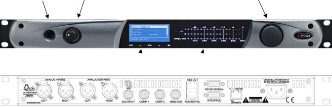
The following illustrations show the location of the various controls and connectors associated with the installation:
Headphone Jack Headphone Level Control |
Jog Wheel |
Main Menu / G/R Metering LCD Display |
Level Meters |
1.Install the Omnia.ONE in the equipment rack using at least two rack screws. If only two screws are used, they MUST be installed in the bottom holes of the rack ears!
2.Connect the audio inputs that are appropriate for your installation. The Omnia.ONE accepts balanced line-level analog audio via the XLR connectors, AES/EBU digital via the bottom RJ-45 jack (using the “StudioHub” standard pinout) or Livewire.
NOTE: Livewire audio I/O is only to be used if you have an existing Axia or other Livewire system. Otherwise, the Livewire Ethernet jack can be used to remote control the Omnia.ONE via its built-in webpage interface. See Appendix C in the full User Manual for details.
3.Connect the audio outputs in a manner that is appropriate for your installation. We suggest using the composite MPX BNC outputs (and therefore the Omnia’s built-in MPX stereo generator) if at all possible for best performance.
4.Connect AC power to the unit (there is no power switch!)
5.Navigate to the Input/Output / Meter Select setting and select Input.
6.Navigate to the Input/Output / Input / Input Src setting and select the Analog, AES/EBU or Livewire input as appropriate for your installation. If your audio source is active, you should now see meter activity on the LED bargraph meters.
7.While driving the inputs with typical program material at normal operating level, navigate back up to the Input/Output / Input menu (by highlighting and clicking on the “<-EXIT” option) and adjust the appropriate input Level control until the peak-reading input bargraph meters are peaking up to at least –15 and up to –12 dBFS or a little higher.
8.Navigate to the Input/Output / Output / FM Options submenu and ensure that the Pre-Emphasis, De-emphasis and BS-412 settings are correct for your system and your location. If you will not be using the Omnia’s built-in stereo generator, it is very important to ensure that the Omnia is the only device providing the FM pre-emphasis (PreEmphasis ON and De-Emphasis OFF) and that any link between the Omnia’s output and the input to the FM exciter is fully linear with no codecs. If this is not possible, the Omnia must be located at the transmitter site, driving the FM exciter directly.
iii
9.If you are using the Omnia’s built-in stereo generator, navigate to the Input/Output / Stereo Generator menu and adjust the appropriate composite output level control (Comp #1 or Comp #2) for 100% modulation on your station’s modulation monitor. Similarly, adjust the Pilot Lvl control so that the 19kHz stereo pilot injection level indicates between 8 and 10 percent as shown on your station’s stereo modulation monitor. If your modulation monitor does not show pilot injection but you are certain that the total modulation is correct at 100%, simply set the Pilot Lvl control to 9.0%.
If you are using the AES/EBU output to feed pre-emphasized audio to your linear STL or digital exciter, navigate instead to the Input/Output / Output menu and adjust the appropriate output level control for the equipment that follows the Omnia.ONE. Ensure that any limiters, clippers and/or pre-emphasis in the exciter/transmitter are defeated.
10.Navigate back to the Main Menu, highlight Preset: and click. Rotate the jog wheel to display the preset you would like to start with and click to select it. Go through all of the presets and start with one that sounds best to you.
11.We suggest that each time you try a new factory preset, you adjust the Clip Drive in the Processing / Adjust Processing / Clipper menu as follows: Starting with the default setting for a preset, adjust it down in 0.5 dB steps until the loudness just drops below the desired level and then bring it up slightly from there. This should be the optimum setting for your station and market. With most presets, there should be room to turn it up a bit as well if a bit more loudness is needed. Turn it up just enough to achieve the desired loudness level. If you have to turn it up too much, to the point where distortion becomes obtrusive, it would probably be best to start with a more aggressive preset.
The Omnia.ONE Quick-Start Setup is now complete. For more detailed installation and operating instructions (including details about every control function) and to learn about some of the features that make the Omnia.ONE unique, please refer to the latest version of the full Omnia.ONE user manual available on the Omnia website here:
http://omniaaudio.com/manuals
iv

Omnia.ONE.SG Quick-Start Setup
We know that you’re probably in a hurry to begin using your new Omnia.ONE.SG. If you have technical expertise and previous knowledge of stereo generator fundamentals, using this guide will get you up and running as quickly as possible. Please refer to the full User Manual for additional installation and setup information.
The following illustrations show the location of the various controls and connectors associated with the installation:
Headphone Jack Headphone Level Control |
Jog Wheel |
Main Menu / G/R Metering LCD Display |
Level Meters |
1.Installation: Install the Omnia.ONE.SG in the equipment rack using at least two rack screws. If only two screws are used, they MUST be installed in the bottom holes of the rack ears!
2.Connect the audio inputs that are appropriate for your installation. These should originate from an external FM audio processor and ideally should be pre-emphasized and fully band limited to 16kHz.
3.Connect the Omnia’s composite MPX BNC output(s) as appropriate for your installation to your FM exciter’s baseband composite MPX input or composite STL transmitter.
4.Connect AC power to the unit (there is no power switch!)
5.Navigate to the Discrete I/O / Meter Select setting and select Input.
6.Navigate to the Discrete I/O / Input / Input Src setting and select the Analog, AES/EBU or Livewire input as appropriate for your installation. If your audio source is active, you should now see meter activity on the LED bargraph meters.
Input Calibration: The Omnia ONE.SG is designed to accept pre-processed audio from an external FM audio processor. Ideally, this audio should be pre-emphasized and sourced only through a lossless link using Livewire or AES/EBU. Analog L/R XLR input can also be accepted. Since the Omnia ONE.SG includes a composite clipper, it is very important to calibrate the input level properly so that when the Composite Clip Drive control is set to 0.0, no composite clipping is taking place.
7.Using typical program material, turn up the main clipper drive on your external FM processor temporarily to provide a more steady “worst-case” level at the input of the Omnia ONE.SG. If using a digital output on the external FM processor, set its peak output level to -12.0dBFS if possible. If so, set the Omnia’s input Level control in the Discrete I/O / Input menu to 0.0dB to start.
NOTE: The Omnia ONE SG’s input meters are specially calibrated with higher resolution above -12dBFS for easy and precise input level calibration. The first yellow LED comes on at -12.1dBFS, the second at -11.9dBFS and subsequent ones every 0.2dB above that. The composite clip point (with 0.0dB drive setting) is -12.0dBFS.
v
8.In the Discrete I/O / Input submenu, adjust the appropriate input Level control until the peak-reading input bargraph meters are just lighting only the first one or two yellow LEDs. If there is some overshoot in the output of your external FM processor or the link between it and the Omnia ONE.SG, more than the first LED may light. This should be OK as long as there is not more than a dB or so of overshoot. If there is more overshoot than that, you may need to lower the input level a bit. Be sure in any case that the red “0”dBFS LED’s never light.
9.Ideally, the de-emphasis in the output of your external FM processor should be defeated so that the Omnia ONE.SG is receiving a pre-emphasized, 16kHz band-limited signal. If not, you can turn pre-emphasis and low-pass filtering on. Navigate to the Stereo Generator / Adjust SG submenu and ensure that the Emph Std (50us or 75us), PreEmph (OFF or ON) and Input LPF (OFF or ON) settings are correct for your system and your location.
10.Here in the Stereo Generator / Adjust SG submenu, navigate down to the Comp #1 or Comp #2 controls and adjust the appropriate one for 100% modulation on your station’s modulation monitor. Similarly, adjust the Pilot Lvl control so that the 19kHz stereo pilot injection level indicates between 8 and 10 percent as shown on your station’s stereo modulation monitor. If your modulation monitor does not show pilot injection but you are certain that the total modulation is correct at 100%, simply set the Pilot Lvl control to 9.0%.
11.To save your settings as an SG Config preset, navigate to the Save SG Config setting in the Stereo Generator menu, click on “Name”, enter a preset name using the jog wheel, turn the jog wheel one more click clockwise and click on “Save”. Similarly, I/O configuration presets can also be saved from the Discrete I/O menu.
12.Remember to return your external FM processor’s main clipper drive control to its previous level.
NOTE: To engage the special single-sideband mode available in the Omnia ONE .SG, navigate to the Stereo Generator / Adjust SG submenu and set the SB Mode control to “SSB”. No other adjustments should be needed.
The Omnia.ONE Quick-Start Setup is now complete. For more detailed installation and operating instructions (including details about every control function) and to learn about some of the features that make the Omnia.ONE unique, please refer to the latest version of the full Omnia.ONE user manual available on the Omnia website here:
http://omniaaudio.com/manuals
vi

Omnia.ONE AM Quick-Start Setup
We know that you’re probably in a hurry to begin using your new Omnia.ONE. If you have technical expertise and previous knowledge of audio processor fundamentals, using this Quick-Start guide will get you up and running as quickly as possible. Please refer to the full User Manual for additional installation and setup information.
The following illustrations show the location of the various controls and connectors associated with the installation:
Headphone Jack Headphone Level Control |
Jog Wheel |
Main Menu / G/R Metering LCD Display |
Level Meters |
1.Install the Omnia.ONE in the equipment rack using at least two rack screws. If only two screws are used, they MUST be installed in the bottom holes of the rack ears!
2.Connect the audio inputs that are appropriate for your installation. The Omnia.ONE accepts balanced line-level analog audio via the XLR connectors, AES/EBU digital via the bottom RJ-45 jack (using the “StudioHub” standard pinout) or Livewire.
NOTE: Livewire audio I/O is only to be used if you have an existing Axia or other Livewire system. Otherwise, the Livewire Ethernet jack can be used to remote control the Omnia.ONE via its built-in webpage interface. See Appendix C in the full User Manual for details.
3.Connect the audio outputs in a manner that is appropriate for your installation. Normally this will be mono balanced analog output to your AM transmitter using either the LEFT or RIGHT output XLR. If you have 2 transmitters, you can use one output for each transmitter and thus have separate level adjustments for each.
4.Connect AC power to the unit (there is no power switch!)
5.Navigate to the Input/Output / Meter Select setting and select Input.
6.Navigate to the Input/Output / Input / Input Src setting and select the Analog, AES/EBU or Livewire input as appropriate for your installation. If your audio source is active, you should now see meter activity on the LED bargraph meters.
7.If you will be running in mono, navigate to the Input/Output / Input / Mono Mode and select the desired mode. Mono L will feed the left channel input’s audio to both output channels, Mono R the same for the right channel input. Mono L+R will sum the left & right inputs and feed the sum to both outputs.
8.While driving the input with typical program material at normal operating level, navigate to the Input/Output / Input menu and adjust the appropriate input Level control until the peak-reading input bargraph meters are peaking up to at least –15 and up to –12 dBFS or a little higher.
vii
9. Navigate to the Input/Output / Output / AM Options submenu and ensure that the Output Polarities, LPF Frequency, Asym Mod and Tilt (normally only used for older plate-modulated transmitters) adjustments are correct for your system and your location. If you will be using asymmetrical modulation to increase your positive modulation above 100%, ensure that when the Asym Mod control is turned up, only the positive modulation peaks are increasing, not the negative peaks. If you find the opposite is true, select Invert for the appropriate output in the menu above.
NOTE: To help make setting modulation levels and positive peaks easier, temporarily set the Processing / Adjust Processing / Clipper / Clip Drive control to a high setting (such as 3.0dB).
10.Navigate to the Input/Output / Output menu and adjust the appropriate control so that the output level is correct for the equipment that follows the Omnia.ONE. Typically this will be the modulation level of your AM transmitter. Ensure that the negative peaks never hit full-cutoff (100%) and then, if desired, increase the asym mod control until positive peak modulation is between 120-125%.
11.Remember to return the Clip Drive control to its previous level.
12.Navigate back to the Main Menu, highlight Preset: and click. Rotate the jog wheel to display the preset you would like to start with and click to select it. Go through all of the presets and start with one that sounds best to you.
The Omnia.ONE Quick-Start Setup is now complete. For more detailed installation and operating instructions (including details about every control function) and to learn about some of the features that make the Omnia.ONE unique, please refer to the latest version of the full Omnia.ONE user manual available on the Omnia website here:
http://omniaaudio.com/manuals
viii
Omnia.ONE Multicast / DAB / Studio Pro
Quick-Start Setup
We know that you’re probably in a hurry to begin using your new Omnia.ONE. If you have technical expertise and previous knowledge of audio processor fundamentals, using this Quick-Start guide will get you up and running as quickly as possible. Please refer to the full User Manual for additional installation and setup information.
The following illustrations show the location of the various controls and connectors associated with the installation:
Headphone Jack Headphone Level Control |
Jog Wheel |
Main Menu / G/R Metering LCD Display |
Level Meters |
1.Install the Omnia.ONE in the equipment rack using at least two rack screws. If only two screws are used, they MUST be installed in the bottom holes of the rack ears!
2.Connect the audio inputs that are appropriate for your installation. The Omnia.ONE accepts balanced line-level analog audio via the XLR connectors, AES/EBU digital via the bottom RJ-45 jack (using the “StudioHub” standard pinout) or Livewire.
NOTE: Livewire audio I/O is only to be used if you have an existing Axia or other Livewire system. Otherwise, the Livewire Ethernet jack can be used to remote control the Omnia.ONE via its built-in webpage interface. See Appendix C in the full User Manual for details.
3.Connect the audio outputs in a manner that is appropriate for your installation. Choices are balanced line-level analog audio via the XLR connectors, AES/EBU digital via the top RJ-45 jack (using the “StudioHub” standard pinout) or Livewire. All outputs are active simultaneously.
4.Connect AC power to the unit (there is no power switch!)
5.Navigate to the Input/Output / Meter Select setting and select Input.
6.Navigate to the Input/Output / Input / Input Src setting and select the Analog, AES/EBU or Livewire input as appropriate for your installation. If your audio source is active, you should now see meter activity on the LED bargraph meters.
7.While driving the inputs with typical program material at normal operating level, navigate back up to the Input/Output / Input menu (by highlighting and clicking on the “<-EXIT” option) and adjust the appropriate input Level control until the peak-reading input bargraph meters are peaking up to at least –15 and up to –12 dBFS or a little higher.
8.Navigate to the Input/Output / Output menu and adjust the appropriate control so that the output level is correct for the equipment that follows the Omnia.ONE.
ix
9.Navigate back to the Main Menu, highlight Preset: and click. Rotate the jog wheel to display the preset you would like to start with and click to select it. It is best to go through all of the appropriate presets and start with one that sounds best to you.
The Omnia.ONE Quick-Start Setup is now complete. For more detailed installation and operating instructions (including details about every control function) and to learn about some of the features that make the Omnia.ONE unique, please refer to the latest version of the full Omnia.ONE user manual available on the Omnia website here:
http://omniaaudio.com/manuals
x
Table Of Contents |
|
Welcome to Omnia.ONE!........................................................................................................... |
i |
What’s New?.................................................................................................................... |
i |
President’s Message:........................................................................................................ |
i |
Omnia.ONE FM Quick-Start Setup........................................................................................... |
iii |
Omnia.ONE.SG Quick-Start Setup.............................................................................................. |
v |
Omnia.ONE AM Quick-Start Setup ......................................................................................... |
vii |
Omnia.ONE Multicast / DAB / Studio Pro Quick-Start Setup................................................ |
ix |
S A F E T Y I N S T R U C T I O N S .................................................................................... |
xv |
HAZARD / WARNING LABELS............................................................................................ |
xvi |
Manual Update Notification..................................................................................................... |
xvii |
Chapter-1: Installation .................................................................................................................. |
1 |
Pre-Installation Tasks............................................................................................................ |
1 |
About This Manual................................................................................................................ |
1 |
Omnia.ONE Components...................................................................................................... |
1 |
AC Power Environment ........................................................................................................ |
1 |
Installation & Connections ................................................................................................... |
2 |
Rack Mounting & Grounding ............................................................................................. |
2 |
AC Mains Power................................................................................................................. |
2 |
Rear Panel Connections ........................................................................................................ |
3 |
Analog Audio Inputs and Outputs ...................................................................................... |
3 |
A Note about Relative Phase: ............................................................................................. |
3 |
Stereo Generator Connections (FM Style Only)................................................................. |
3 |
Composite Outputs 1 & 2 (BNC) (Active on FM and SG Styles Only).......................... |
3 |
19 kHz Sync Output (BNC) (Active on FM and SG Styles Only) .................................. |
4 |
SCA Input (BNC) (Active on FM and SG Styles Only).................................................. |
4 |
Ethernet / Livewire Connection.......................................................................................... |
5 |
RS-232 Modem Connection (DB-9M)* ............................................................................. |
5 |
General Purpose Interface (GPI) (DB-9F)*........................................................................ |
6 |
Powering Up ........................................................................................................................... |
6 |
Chapter-2: Getting To Know Your Omnia.ONE........................................................................ |
7 |
The Omnia.ONE User Interface........................................................................................... |
7 |
Headphone Level Control................................................................................................... |
7 |
Level Meters & Processing Bargraphs ............................................................................... |
7 |
Audio I/O Level Display..................................................................................................... |
8 |
Processing Meter Display ................................................................................................... |
8 |
Main Menu.......................................................................................................................... |
9 |
Using the Jog Wheel ......................................................................................................... |
10 |
User Interface Tutorial – Input Source Selection and Peak Level Setting ....................... |
11 |
Proper Setting of Input Levels ....................................................................................... |
11 |
An Important Word about Time Delay ............................................................................. |
12 |
Chapter-3: Getting the Sound You Want.................................................................................. |
13 |
FM Style................................................................................................................................ |
13 |
xi
The Factory Presets........................................................................................................... |
13 |
Increasing Density/Loudness............................................................................................ |
14 |
Adding More Detail — When Loudness Isn’t the Last Word.......................................... |
15 |
Air-Sound Equalization Changes...................................................................................... |
15 |
Thunder Bass .................................................................................................................... |
16 |
AM Style ............................................................................................................................... |
16 |
Using Omnia.ONE AM with Early PWM Transmitters................................................... |
16 |
The Factory Presets........................................................................................................... |
17 |
Increasing Density/Loudness............................................................................................ |
18 |
Adding More Detail — When Loudness Isn’t the Last Word.......................................... |
19 |
Air-Sound Equalization Changes...................................................................................... |
19 |
Thunder Bass .................................................................................................................... |
20 |
Multicast/DAB Style ............................................................................................................ |
20 |
Purpose.............................................................................................................................. |
20 |
Sensus Technology: Audio Processingx3 .................................................................... |
21 |
Overview ....................................................................................................................... |
21 |
Codec Provisioning ...................................................................................................... |
21 |
Omnia.ONE Multicast and HD Radio.................................................................... |
21 |
So… what’s so smart about Sensus ?....................................................................... |
22 |
Loudness Processing and Codecs ..................................................................................... |
22 |
A Word About Density, Clarity, and Intelligibility .......................................................... |
23 |
Quality Versus Density..................................................................................................... |
23 |
Increasing Density/Loudness............................................................................................ |
24 |
Adding More Detail—When Loudness Isn’t the Last Word............................................ |
24 |
Equalization (EQ) Changes............................................................................................... |
25 |
Thunder Bass .................................................................................................................... |
25 |
Coded Audio Considerations ............................................................................................ |
26 |
Studio Pro Style.................................................................................................................... |
26 |
Purpose.............................................................................................................................. |
26 |
Delay Throughput ............................................................................................................. |
26 |
Equalization (EQ) Changes............................................................................................... |
27 |
Presets ............................................................................................................................... |
27 |
Bass Enhancement ............................................................................................................ |
28 |
Chapter-4: Main Menu Selections.............................................................................................. |
29 |
FM Style................................................................................................................................ |
29 |
Preset................................................................................................................................. |
30 |
Processing ......................................................................................................................... |
30 |
Save Preset........................................................................................................................ |
31 |
Delete Preset ..................................................................................................................... |
31 |
Rename Preset................................................................................................................... |
32 |
<-Exit ................................................................................................................................ |
32 |
Adjust Processing.............................................................................................................. |
32 |
Input/Output...................................................................................................................... |
40 |
Administrative................................................................................................................... |
47 |
Lock Front Panel............................................................................................................... |
49 |
xii
SG Style................................................................................................................................. |
50 |
Stereo Generator ............................................................................................................... |
50 |
Discrete I/O....................................................................................................................... |
52 |
Administrative................................................................................................................... |
57 |
Lock Front Panel............................................................................................................... |
58 |
AM Style ............................................................................................................................... |
59 |
Preset................................................................................................................................. |
60 |
Processing ......................................................................................................................... |
60 |
Save Preset........................................................................................................................ |
60 |
Delete Preset ..................................................................................................................... |
61 |
Rename Preset................................................................................................................... |
61 |
<-Exit ................................................................................................................................ |
62 |
Adjust Processing.............................................................................................................. |
62 |
Input/Output...................................................................................................................... |
70 |
Administrative................................................................................................................... |
78 |
Lock Front Panel............................................................................................................... |
80 |
Multicast/DAB Style ............................................................................................................ |
81 |
Preset................................................................................................................................. |
82 |
Processing ......................................................................................................................... |
82 |
Save Preset........................................................................................................................ |
82 |
Delete Preset ..................................................................................................................... |
83 |
Rename Preset................................................................................................................... |
83 |
<-Exit ................................................................................................................................ |
83 |
Adjust Processing.............................................................................................................. |
84 |
Input/Output...................................................................................................................... |
92 |
Administrative................................................................................................................... |
97 |
Lock Front Panel............................................................................................................... |
99 |
Studio Pro Style.................................................................................................................. |
100 |
Preset............................................................................................................................... |
100 |
Processing ....................................................................................................................... |
100 |
Adjust Processing............................................................................................................ |
101 |
Input/Output.................................................................................................................... |
108 |
Administrative................................................................................................................. |
113 |
Lock Front Panel............................................................................................................. |
115 |
Appendix A: Performance Specifications................................................................................ |
117 |
Omnia.ONE FM.................................................................................................................... |
117 |
Omnia.ONE SG..................................................................................................................... |
120 |
Omnia.ONE AM ................................................................................................................... |
123 |
Omnia.ONE Multicast/DAB & Studio Pro......................................................................... |
126 |
Appendix B: Troubleshooting/Service/Warranty................................................................... |
129 |
Diagnostics and Error Messages....................................................................................... |
130 |
Electrical and mechanical safety note!............................................................................. |
131 |
Narrowing down problems................................................................................................ |
131 |
Obtaining Service............................................................................................................... |
132 |
Via the World Wide Web ............................................................................................... |
132 |
Via E-Mail ...................................................................................................................... |
132 |
Via Phone........................................................................................................................ |
132 |
xiii
Warranty ............................................................................................................................ |
133 |
Appendix C: Remote Control and Software Update Procedure .......................................... |
135 |
Remote Control .................................................................................................................. |
135 |
Remote ............................................................................................................................ |
136 |
Preset Tab..................................................................................................................... |
137 |
Processing Tab............................................................................................................. |
137 |
In Tab........................................................................................................................... |
138 |
Out Tab ........................................................................................................................ |
139 |
IO Tab .......................................................................................................................... |
139 |
Encode Tab (FM Style Only)....................................................................................... |
139 |
Livewire .......................................................................................................................... |
140 |
File Transfer.................................................................................................................... |
141 |
Preset File Transfer...................................................................................................... |
141 |
I/O Configuration File Transfer ................................................................................... |
142 |
Trigger Scripts ................................................................................................................ |
142 |
Software Update Procedure.............................................................................................. |
143 |
Special Notes: ................................................................................................................. |
143 |
Appendix D: GPI using the “INTERFACE” connector (New in Version 2.6).................... |
147 |
xiv
S A F E T Y I N S T R U C T I O N S
1.Read All Instructions. All safety and operating instructions must be read before operating the product.
2.Retain All Instructions. All safety and operating instructions must be retained for future reference.
3.Heed All Warnings. All warnings on the product and those listed in the operating instructions must be adhered to.
4.Follow All Instructions. All operating and product usage instructions must be followed.
5.Heat. This product must be situated away from any heat sources such as radiators, heat registers, stoves, or other products (including power amplifiers) that produce heat.
6.Ventilation. Slots and openings in the product are provided for ventilation. They ensure reliable operations of the product, keeping it from overheating. These openings must not be blocked nor covered during operation. This product should not be placed into a rack unless proper ventilation is provided through following the manufacturer's installation procedures.
7.Water and Moisture. Do not use this product near water – for example; near a bath tub, wash bowl, kitchen sink or laundry tub; in a wet basement; or near a swimming pool or the like.
8.Attachments. Do not use any attachments not recommended by the product manufacturer as they may cause hazards.
9.Power Sources. This product must be operated from the type of power source indicated on the marking label and in the installation instructions. If you are not sure of the type of power supplied to your facility, consult your local power company.
10.Grounding and Polarization. This product is equipped with a polarized AC plug with integral safety ground pin. Do not defeat the safety ground in any manner.
11.Power Cord Protection. Power supply cords must be routed so that they are not likely to be walked on nor pinched by items placed upon or against them. Pay particular attention to the cords at AC wall plugs and convenience receptacles, and at the point where the cord connects to the product.
12.Lightning. For added protection for this product during a lightning storm, or when it is left unattended and unused for long periods of time, unplug it from the AC wall outlet. This will prevent damage to the product due to lightning and power supply surges.
13.Overloading. Do not overload AC wall outlets, extension cords, or integral convenience outlets as this can result in a fire or electric shock hazard.
14.Object and Liquid Entry. Never push objects of any kind into this product through openings as they may touch dangerous voltage points or short out parts that could result in a fire or electric shock. Never spill liquid of any kind into the product.
15.Accessories. Do not place this product on an unstable cart, stand, tripod, bracket, or table. The product may fall, causing serious damage to a child or adult, and serious damage to the product. Any mounting of the product needs to follow manufacturer's installation recommendations.
16.A Product and Cart Combination should be moved with care. Quick stops, excessive force, and uneven surfaces may cause the product and the cart combination to overturn.
17.Servicing. Refer all servicing of the product to qualified service personnel.
18.Damage Requiring Service. Unplug this product from the AC wall outlet and refer servicing to qualified service personnel under the following conditions:
•When the AC plug is damaged.
•If liquid has been spilled or objects have fallen into the equipment.
•If the product has been exposed to rain or moisture.
•If the product does not operate normally (following operating instructions).
•If the product has been dropped or damaged in any way.
•When the product exhibits a distinct change in performance. This indicates a need for service.
19.Replacement Parts. When replacement parts are required, be sure the service technician has used replacement parts specified by the manufacturer or that have the same characteristics as the original parts. Unauthorized substitutions may result in fire, electric shock, or other hazards.
20.Safety Check. Upon completion of any repairs to this product, ask the service technician to perform safety checks to determine that the product is in safe operating condition.
21.Cleaning. Do not use liquid cleaners or aerosol cleaners. Use only a damp cloth for cleaning.
xv

HAZARD / WARNING LABELS
The Exclamation Point symbol, within an equilateral triangle, alerts the user to the presence of important operating and maintenance (servicing) instructions in product literature and instruction manuals.
The Lightning Flash With Arrowhead symbol, within an equilateral triangle, alerts the user to the presence of non-insulated dangerous voltages within the product's enclosure that may be of sufficient magnitude to constitute a risk of electric shock.
WARNING -- This equipment generates, uses, and can radiate radio frequency energy. If not installed and used in accordance with the instructions in this manual it may cause interference to radio communications. The device has been formally submitted for testing and found to comply with the limits for a Class B computing device (pursuant to subpart J of Part 15 FCC Rules) and has been designed to provide reasonable protection against such interference when operated in a commercial environment. Operation of this equipment in a residential area may cause interference, and the user and at his expense will be required to take any measures required to correct interference.
CANADA WARNING – This digital apparatus does not exceed the Class B limits for radio noise emissions set out in the Radio Interference Regulations of the Canadian Department of Communications. Le present appareil numerique n'emet pas de bruits radioelectriques depassant les limits applicables aux brouillage radioelectrique edicte par le ministere des Communications de Canada.
CE CONFORMANCE – This device complies with the requirements of the EEC Council Directives: 93/68/EEC (CE Marking); 73/23/EEC (Safety – low voltage directive); 89/336/EEC (electromagnetic compatibility). Conformity is declared to those standards: EN50081-1, EN50082-1.
xvi

LITHIUM BATTERY CAUTION – There is a danger of explosion if the internal battery is replaced incorrectly or shorted. Replace the battery only with same or equivalent type recommended by the manufacturer. Dispose of used batteries according to the manufacturer's instructions.
USE OF SHIELDED CABLING – In order to conform to the CE requirements for High Frequency radiation, shielded cables must be used for all audio and data connections.
NOTE: When the unit is operated in an extremely high RF environment, it may be helpful to connect cable shields to the XLR-connector terminal that connects cable shield to chassis ground, not to pin 1. Additionally, a 0.01uF capacitor connected between XLR pin-1 and the chassis terminal may be helpful in some instances.
RoHS COMPLIANCE – The RoHS Directive stands for "the restriction of the use of certain hazardous substances in electrical and electronic equipment". This Directive bans the placing on the European market of new electrical and electronic equipment containing more than agreed levels of lead, cadmium, mercury, hexavalent chromium, polybrominated biphenyl (PBB) and polybrominated diphenyl ether (PBDE) flame retardants. Omnia.ONE FM is in compliance with the EU RoHS Directive.
Manual Update Notification
Audio Processing – a unique art form that we take very seriously!
As part of our dedication to the science of audio processing we will continue to improve and update the Omnia product and its documentation based on our ongoing research, real-world field experience, and the valued input from our many thousands of loyal customers.
We strongly encourage our customers to visit our Omnia website for product enhancement announcements, software updates, updated user manuals, and customer support bulletins.
The following URLs have been included for your convenience:
Manual Updates |
http://www.omniaaudio.com/support/manuals.htm |
|
|
Frequently Asked Questions (FAQ) |
http://www.omniaaudio.com/support/faq.htm |
|
|
Tech Tips & Support Bulletins |
http://www.omniaaudio.com/tech/tips.htm |
|
|
Software Upgrades & Remote Software |
http://www.omniaaudio.com/support/updates.htm |
|
|
White Papers & Technical Discussions |
http://www.omniaaudio.com/tech/default.htm |
|
|
xvii
Chapter-1: Installation
Pre-Installation Tasks
Please take a few minutes to read through this chapter before proceeding with the installation. This section offers common procedures for installing your new Omnia.ONE processor.
About This Manual
This manual is now written to cover all 4 styles of the Omnia.ONE. This chapter will cover only general installation topics. Topics unique to a specific style are covered in style-specific sections within Chapters 3 and 4. The latest version of this manual is always available for download from the Omnia website here: http://www.omniaaudio.com/support/manuals.htm
Omnia.ONE Components
By now, you’ve unpacked the shipping carton to gain access to this manual. Now is the time to inspect the Omnia.ONE unit and its shipping carton for any signs of shipping damage. Such damage must be reported to your carrier for any claims. The Omnia.ONE shipping box includes the following components:
Omnia.ONE processor.
Omnia.ONE Operating Manual.
Warranty Registration Card. (Please complete the form and return/FAX it to Telos/Omnia)
Two IEC Power Cords, one of the USA/Canada style, and one of the Euro style.
One each Male and Female XLR to StudioHUB RJ45 adaptor cables.
AC Power Environment
The Omnia.ONE subsystem is a DSP-based microcomputer, and therefore requires reasonably clean AC power, just as any modern computer system does. And even though the Omnia.ONE power supply is equipped with robust AC transient suppression, we recommend that an “online” style (non-switching type) Uninterruptible Power Supply (UPS) with transient surge suppression be employed.
At transmitter sites there can be heavy transients on the power lines as well as significant surges introduced into the power system by frequent lighting strikes. These are unwelcome power line events and can damage even the most robust equipment. Therefore you should give the AC power environment and installation practices thorough consideration before plugging in the Omnia.ONE (or any other microcomputer-based equipment).
A White Paper by one of our Support Engineers can be found on the Telos Systems website at the URL listed below. It details proper grounding and contains links to some surge suppression products for both the power mains and the often-neglected telephone, Ethernet and ISDN line connections that can (and do) conduct powerful surges into the equipment.
http://www.telos-systems.com/techtalk/surge.htm
1
Installation & Connections
Rack Mounting & Grounding
The Omnia.ONE requires one RU (1.75" [44.45 mm]) of rack space. Rack mount the unit using four rack screws. If only two screws are going to be used, they should be in the bottom holes in the Omnia front panel. No other twoscrew mounting arrangement will prevent distortion of the front panel!
Adequate ventilation should be provided, and it is always good engineering practice to allow one blank rack space immediately above and below the Omnia, especially if equipment generating significant heat is located below the unit. You may install 1RU (1.75") vented or solid rack panels to fill these spaces.
The processor should be installed into a properly grounded 19" equipment rack.
It is a good idea, especially at transmitter sites, to run a separate ground strap or braid from the Omnia.ONE’s chassis to a solid rack or station ground point. Although no separate ground lug is provided, the end of the strap or braid can be clamped under the Omnia’s top cover using the Omnia’s existing top cover screws.
AC Mains Power
AC Power Connection
Omnia.ONE utilizes an un-switched EMI-filtered IEC power-entry module.
Omnia.ONE’s automatic voltage–sensing, high-efficiency switching power supply allows it to operate on AC mains voltages from 100 to 240 VAC and from source frequencies of either 50 or 60 Hz.
In the USA or Canada, plug the provided IEC type AC power cord into the unit and then into a grounded AC outlet.
Outside of the USA you must use the appropriate power cord that complies with local electrical regulations.
After power is first applied to the Omnia.ONE, the LCD screen, the “in” and “out” LED’s and the rightmost segments of the LED bargraph meters should light.
After about 20 seconds the LCD screen should show “Omnia.ONE” and at about 30 seconds the Main Menu should appear. Once the Main Menu appears the unit is ready for use.
2

Rear Panel Connections
Analog Audio Inputs and Outputs
Balanced XLR-type connectors are used for the analog audio. Both analog and digital input sources may be connected simultaneously, however, only the input source that has been selected is active. Analog/Digital/Livewire Input source selection is done through the “Input Src” (Input Source) software parameter setting in the Input submenu of the Input/Output menu.
All outputs are active simultaneously.
The stereo analog inputs are designed for standard +4dBu balanced signals. Pin 2 is Hot.
Individual Left and Right analog outputs are available on two male XLR jacks. Pin 2 is Hot.
A Note about Relative Phase:
If the relative phase of your installation (including the Omnia.ONE) differs from that of your existing system, your announcers may feel that they sound “weird” in their headphones. If this occurs, then the relative phase of the processor is 180 degrees from what your air talent is used to. To remedy this, you can either reverse the polarity of both of the analog inputs or simply change the “Invert” setting to [Both] in the Input submenu of the
Input/Output menu.
Stereo Generator Connections (FM Style Only)
Four standard female BNC connectors comprise the Omnia.ONE’s stereo generator connections.
There are two composite MPX outputs with independent software level controls, one SCA input with level adjust trimpot and one 19 kHz pilot sync output.
Composite Outputs 1 & 2 (BNC) (Active on FM and SG Styles Only)
These two low impedance outputs (Composite 1 and Composite 2) are each capable of driving up to 100 feet of RG-58A/U coax cable. The output levels are individually adjustable so the unit can operate as a “composite DA” to drive a variety of equipment. The output levels and other stereo generator settings are set through software parameters in the Stereo Generator submenu of the Input/Output menu. An internal jumper sets the
3

output impedance to either 5 ohms (the factory setting) or 75 ohms. The default setting is appropriate for the vast majority of exciter connections. However, in the event that a higher source impedance is required, a jumper can be moved (one for each composite output) on the motherboard to change the source impedance to 75 ohms. For reference, JP10 is for Composite #1, and JP9 is for Composite #2.
Jumpers JP7 & JP8 are also available if you need to limit the maximum peak-to-peak output voltage from the composite outputs to 4v p-p instead of the normal 10v p-p. They default to the Normal (10v p-p) setting.
19 kHz Sync Output (BNC) (Active on FM and SG Styles Only)
This TTL-level 19 kHz square wave output can be used as the reference signal for most RDS or SCA generators that operate at 57 kHz or other multiple of the 19 kHz pilot frequency. This Sync output is phase and frequency locked to the stereo pilot. When this signal is used to synchronize an external SCA or RDS generator, this locking assures that no difference frequencies exist which may cause intermodulation components between the pilot and the SCA signal.
SCA Input (BNC) (Active on FM and SG Styles Only)
Any SCA or RDS signal above 53 kHz can be added to the composite outputs of the Omnia.ONE by connecting the signal to the SCA INPUT connector. The SCA signal is mixed in the analog domain directly into both composite outputs. A high-pass filter on the SCA input provides SCA to main-channel crosstalk protection. The SCA injection level can be adjusted using the rear panel Gain trimpot.
AES/EBU Digital Input, AES/EBU External Sync Input, and AES/EBU Output
(GREEN Male XLR)
(GREEN Female XLR)
(RED Female XLR)
The digital AES/EBU (AES-3) inputs (IN and EXT. SYNC) use industry-familiar RJ-45 connectors and utilize the StudioHUB+ wiring standard1. They accept any sampling rate between 32kHz and 96kHz. No user adjustment of the sample rate is necessary on the AES-3 input as a high-quality digital sample rate converter is built in.
There is one AES-3 output on a standard RJ-45 connector that provides either an internally generated output sample rate of 48 kHz or the sample rate can be locked to an external AES/EBU signal applied to pins 3 & 6 of the the AES IN / SYNC IN connector or to the AES/EBU input signal. These options are selectable using the “Samp. Rate” setting in the Output submenu of the Input/Output menu.
Note: The analog and digital outputs are active simultaneously.
1 More information about the StudioHUB+ wiring scheme can be found at: http://www.studiohub.com/
For your convenience, two XLR adaptor cables are supplied with the unit. The male XLR lead with the GREEN shrink tubing is used for AES OUT. The male XLR lead with the RED shrink tubing is not used.
The female XLR lead with the GREEN shrink tubing is used for AES IN and the female XLR lead with the RED shrink tubing is used for AES EXTERNAL SYNC IN.
4

Ethernet / Livewire Connection
The RJ-45 10BaseT / 100BaseT Ethernet / Livewire I/O jack can be used simultaneously for both TCP/IP based remote control of your Omnia.ONE and audio input/output to your existing Livewire network.
Ethernet 10BaseT/100BaseT Remote and Livewire I/O
RS-232 Modem Connection (DB-9M)*
This DB9-male connector can be used to connect an external dialup modem for a bi-directional computer remote control connection.1
NOTE: This connector is for a remote control external modem connection only. Please see Appendix B for information on how to use a terminal program along with an internal RS-232 connector for troubleshooting purposes.
RS-232 Modem Port
NOTE: You must use a standard straight-through serial cable and not a null modem cable when connecting the RS232 connector of the Omnia and the external modem. Typically this would be 9-pin to 25-pin cable. (External modems traditionally have 25 pin connectors in "DCE" configuration. The Omnia.ONE has a 9 pin in "DTE" configuration, so the standard 9-pin to 25-pin cable will work).
1 The setup and operation of the Omnia Remote Control application is covered in detail in Appendix C.
*Please note that the RS-232 Modem functionality is not yet implemented in the current software but will be available with a free downloadable software update. Please check the Omnia website for new software announcements, download links and manual updates at: http://www.omniaaudio.com/
5

General Purpose Interface (GPI) (DB-9F)*
This DB9-female connector serves as a four-input, optoisolated interface to the Omnia's internal GPI functions. Four of the pins are “ground-sink” inputs, one is a bias voltage input, one is a +5V power output, and the remaining three are “ground.” The inputs can be used to dynamically alter the Omnia.ONE’s operation in response to logic transitions on the interface connection.
Full details, including connector pinout, are covered in Appendix D, starting on Page 147.
DB-9M GPI “Interface” Connector
Powering Up
Now you are ready to power up the Omnia.ONE for the first time.
Connect AC power to the unit using the appropriate supplied power cable for your location. (There is no power switch!)
When the Omnia.ONE is first powered on, audio will appear at the analog audio outputs in approximately ten seconds. The AES/EBU and Livewire outputs also become usable at this time however full initialization of the digital ports is not complete for several more seconds and a small audio glitch may be heard when the final sample rate converter initialization is complete. Once the boot process is finished the following Main Menu will appear:
6

Chapter-2: Getting To Know Your Omnia.ONE
The Omnia.ONE User Interface
Now that your Omnia.ONE is rack-mounted, connected to a program audio source, and turned on, you’re ready to learn how to operate it! This chapter covers the Front Panel User Interface, your window into the Omnia.ONE processor.
A front panel jog-wheel with integral push switch, LED bargraph peak-reading level meters and a backlit LCD display that is switchable between menu and AGC/Limiter metering screens make up the primary Omnia.ONE User Interface. The front panel menu access may be password protected to prevent unauthorized tampering with processing or presets.
Omnia.ONE Key Front Panel Features
Headphone Jack Headphone Level Control |
Jog Wheel |
Main Menu / G/R Metering LCD Display |
Level Meters |
Headphone Level Control
A standard ¼" TRS stereo headphone jack is located at the left side of the front panel and allows the processed signal to be monitored. The Headphone volume level control is physically located to the right of the headphone jack. The headphone amplifier itself is a high-headroom design and is driven by its own high quality D/A converter that is independent of the analog XLR outputs. Therefore level changes in either output will not affect the other.
Level Meters & Processing Bargraphs
The top two of the three horizontal meters show digital sample-accurate peak representations of the left and right channel input or output levels. Whether these bargraphs are displaying Input, Analog Output, AES/EBU Output or Livewire Output levels is selectable from within the Input/Output menu. A front panel indicator confirms which level view has been selected, Input or Output.
The bottom horizontal meter (marked “comp / aux”) displays the composite MPX level from the stereo generator before the output level controls. (Active on FM and SG Styles Only)
7

Audio I/O Level Display
Either input or output levels can be displayed on the top 2 (L & R) meters. The highest LED illuminated indicates digital sample-accurate peak signal levels. The meters are calibrated in decibels below full scale digital (0 dBFS) in 2dB steps. 0 dBFS is the absolute maximum level in the digital domain. Levels from –34 dBFS to –14 dBFS are displayed in blue, levels from –12 to –2 dBFS are displayed in yellow and 0 dBFS (the clipping point) is displayed in red. The bottom meter displays the composite MPX signal level referenced to 100% modulation (FM and SG Styles Only).
Audio I/O Level Display
Processing Meter Display
In “Meter Display” Mode the vertical bargraphs show all of the processing activity (the amount of gain reduction) in the AGC, Limiter and Clipper sections within the Omnia.ONE. (varies with style) If the “Menu Display” is currently showing on the Omnia.ONE’s LCD screen, press and hold the jog-wheel for two seconds to switch to the processing meter display as shown below.
To return to the Menu display, simply click the jog wheel once. (See “Using the Jog Wheel” on Page 10)
FM Style Processing Meter Display
AGC Meters |
Limiter/Clipper Meters |
|
|
|
|
||||
W…... Wide Band AGC |
|
L….. Low Band Limiter |
||
L……. Low Band AGC |
|
M…. Mid Band Limiter |
||
M…… Mid Band AGC |
|
P…... Presence Band Limiter |
||
P…… Presence Band AGC |
H….. High Band Limiter |
|||
|
|
S…... Super-High Band Limiter (optional on |
||
|
|
FM style only) |
||
H…… High Band AGC |
|
B….. Bass Clipper |
||
|
|
M…. Main Clipper (AM & FM Styles) |
||
|
|
or F…..Final Limiter (MC & SP Styles) |
||
8

Important Notes:
•A solid white bar will drop downward from the top to display the amount of gain reduction in each processing band. The change from a solid bar to a checkerboard pattern indicates a “gated” condition in that band.
•The wideband AGC and four-band AGCs will recover to a resting gain setting which coincides with the RTZ (Return To Zero) levels set for each band.
•The Clipper meters are peak reading, showing the maximum amount of clipping that occurred over the past 30 milliseconds. The Main clipper meter (FM & AM Styles Only) will indicate higher amounts of clipping on bright program material because the Main Clipper is operating on the preemphasized audio signal. This is normal and does not indicate the perceived amount of audio distortion.
Main Menu
The Omnia.ONE menu system has been designed to be intuitive and simple to use. Most operating parameters can be found under one of the menu headings and sub-headings, allowing adjustments to be made quickly and with ease. Rotating the jog-wheel sequentially highlights each menu item in turn. (See “Using the Jog Wheel” on Page 10)
When the jog wheel is pressed inward (clicked) while a menu item is highlighted it will open that item’s submenu. Similar behavior occurs when selections are made within the various submenus.
To return to the previous level, rotate the jog wheel until <-Exit is highlighted and then press the jog wheel inward. (Click) This will return you to the next highest level in the menu structure. NOTE: Some of the longer menus have an <-Exit option at the top of the menu as well as at the bottom.
The Omnia.ONE Main Menu offers five selections:
•Preset
•Processing
•Input/Output
•Administrative
•Lock Front Panel (not visible in the above screenshot)
9

Using the Jog Wheel
The main user control for the Omnia.ONE is the easy to use jog wheel with its integral push-switch. Using the control is both intuitive and efficient, making it easy to navigate the menu structure of the Omnia.ONE. Processing changes and system adjustments can be quickly made with ease without having to remember multiple controls, their positions, and what they do in each menu. The behavior of the Omnia.ONE's menu system is consistent across pages and is easy to learn. We believe that you will quickly become comfortable with how it works, and appreciate its simplicity.
Clockwise rotation moves the highlighting in a menu downward and increases a value when editing parameters.
Counterclockwise rotation moves the highlighting in a menu upward and decreases a value when editing parameters.
Pressing inward on the jog-wheel activates the Enter, Return or Select button function as follows:
Pressing the jog-wheel inward once (also called “clicking”) selects the highlighted menu item or accepts the current parameter value. Think of it as a vertical mouse button.
Pressing and holding the jog-wheel in for two seconds will switch the LCD screen to a display of the processing meters so that the gain-reduction activity of the AGC and Limiter sections can be monitored.
Clicking once when the metering screen is displayed will return the display to the menu screen.
10
User Interface Tutorial – Input Source Selection and Peak Level Setting
The following two exercises are a useful introduction to the user interface. Start from the Main Menu (as displayed when the unit is first turned on).
The first exercise changes a parameter selection (the Input Source selection):
Rotate the jog-wheel to highlight Input/Output.
Click the jog-wheel (push on the wheel once until a click is felt and release) to bring up the Input/Output menu.
Rotate the jog-wheel to highlight Input and click.
Rotate the jog-wheel to highlight Input Src and click.
The factory default selection for Input Source is Analog. To change the input selection to AES/EBU digital or Livewire, rotate the jog-wheel until [AES/EBU] or [Livewire] is displayed and click. If you are using the analog inputs, rotate the jog wheel to display [Analog] and click to reselect the analog inputs.
To return to the top level of the Main Menu, rotate the jog-wheel to highlight <-EXIT and click. Repeat until the top level (Main Menu) is reached. NOTE: Many of the Omnia.ONE’s menus have an <-EXIT selection at both the top and bottom of the menu.
The next exercise adjusts a parameter that uses a value (the analog master input level setting):
The Main Menu display should still be showing on the LCD screen. If not, click the jog-wheel to display it.
Highlight Input/Output and click.
Highlight Mtr Select, click, rotate the jog wheel until [Input] is displayed and click. This sets the first 2 LED meters to monitor the Left and Right channel input levels.
Rotate the jog wheel clockwise to highlight Input and click.
Rotate the jog wheel to highlight Anlg Level and click the jog-wheel to select the control.
Rotate the jog-wheel CW to increase the input level. Rotate the jog-wheel CCW to decrease the input level. This control adjusts both channels together in precise 0.5 dB steps. The gain in dB is shown to the right of the “control.” Watch the Left and Right channel LED meters while adjusting per the following section below.
Proper Setting of Input Levels
With normal program audio levels applied, a correct input level setting will result in peak indications on the L & R LED meters achieving –12 dBFS or a little higher (just into the yellow). This gain setting corresponds to system headroom of about 12 dB. You may adjust the input level lower for more headroom if you wish. Setting the input level for higher meter indications (less headroom) is strongly discouraged unless there is another level-control device prior to the Omnia.ONE that will keep the input levels from reaching the maximum digital level of 0 dBFS. During normal operation, you should never see the red “0” segments light.
Once the desired level setting is reached, click the jog-wheel to accept that value. This returns the jog-wheel to Select Mode.
You may highlight and click Right Trim to adjust its gain separately from the left channel if the input source is not well balanced. In this mode the right channel gain can be adjusted over a range of plus and minus 3 dB
11
Loading...