


 Loading...
Omnia-6EX / EXi
HD + FM
Broadcast Audio Processor
Installation and Operation Manual
Version 1.4 / June 2005
Applicable to Omnia-6 FM / HDFM / EX and Exi Models
With v7.1.0 Release Software and Higher
Telos Company
|
Omnia ● 2101 Superior Avenue Cleveland, Ohio 44114 USA |
www.omniaaudio.com |
TEL: +1 |
216.241.7225 ● FAX: +1 216.241.4103 ● Email: info@omniaaudio.com |
|
|
Omnia Europe ● Johannistrabe 6 D-85354 Freising Germany |
www.omniaaudio.com |
TEL: +49 |
8161 42467 ● FAX +49 8161 42402 ● Email: europe@omniaaudio.com |

August, 2003
Greetings!
It is with great pleasure to offer you our latest audio processor, Omnia-6EX! First and foremost, I must share my gratitude as well. This new addition continues the evolution of Omnia processing. The worldwide acceptance of our product line has been quite humbling to say the least. As I write this, our audio processors are now deployed by so many leading broadcasters throughout the world that when looking at the list, I am overwhelmed by the recognition that my (originally small) project to improve the sound of radio has gathered. So, it’s to you I say Thank You!
1986 seems like just a short time ago! It was that year, in the engineering shop at Z-100, (WHTZ-FM) New York City that our first product was born, the Vigilante FM Limiter. Now, 16 years later, along with an incredibly talented team of fellow broadcasters and engineers, we offer you a feature rich, and sonically powerful tool - the Omnia-6EX! This processor is not just Frank anymore. It’s a complex effort from a tremendous team that has had only one goal in mind - to raise the bar, yet again, and present you with our best effort possible.
I don't have enough space here to thank each and every one of the Telos/Omnia worldwide team members who have contributed to this product in so many important ways. All I can say is that we would not be where we are today without the heroic and brilliant efforts from all of you working together. It is our goal to set the standard by which all others will be judged. The rules have changed, and Omnia processing is the reason why! What was once a truly small company consisting of only my cat Vito and me has expanded to the point of having the best talent in every area of product design, engineering, and marketing. (Not to mention, we now have the vital assistance of three cats - Omnia, Zephyr, and Mocha.)
If I may say so, our pool of engineers for DSP development and software design is probably the finest in the radio industry. My partner in crime, Steve Church, brought DSP into the broadcasting field in the mid-1980’s and we’ve been strengthening our abilities ever since. Sharing Telos’ ingenuity for DSP design has been tremendously beneficial to our work on Omnia. If you thought the original Omnia made noise on the dial, all I can say is look out! It’s like one of the top-of-the hour station ID’s that Scott Shannon used to jam on Z-100 “Lock It In And Rip The Knob Off!” That's the kind of listener-grabbing power and capability Omnia-6EX delivers!
As HD-Radio evolves, it is worth mentioning that our organization Telos and Omnia were deeply involved behind the scenes with the IBOC developers. Our extensive background in dynamics processing and audio codecs allowed us to be of assistance to iBiquity in development of their system. We were just one of those involved helping them understand the need for a better codec for the AM system, which they have now implemented. As a small reminder, it was the efforts of our Steve Church who introduced the USA to MP3, and MP3 has now evolved into aac. Modestly speaking, no other processing developer has the synergy of being on the leading edge of both coding and dynamics.
Before signing off, I would be remiss not to mention one individual though, Jeff Keith, the leader of Team Omnia. Jeff is quite well known in his own right as an audio processing guru! His years of radio station experience and vast processing knowledge have dominated many a radio market, and now his efforts are an added benefit to Omnia-6EX. His creativity, passion and commitment to our success have helped all the various talented (and sometimes chaotic) crew unite in a common goal. To build a processor so great, it would surpass even my high expectations. Jeff, you and your team have succeeded! Thus, I dedicate Omnia-6EX to you!
Not only do you have in your possession the best sounding audio processor available, you also have the full support of our organization. If you have something to say, we’re here to listen. We’ve been fortunate through the past, that people like you have taken the time to offer us valuable feedback and review of our endeavors. You can now see the result of that, as you are now rewarded with the next step forward!
Without further adieu, it’s time for us to jam! So, as my buddy Scott Shannon would often say to me, “Frank-o, Let’s Crank It Up Man!”
Here’s to Dial Dominance,
Frank Foti
Omnia-6ex Use and Operation Manual – V:1.00
2
S A F E T Y I N S T R U C T I O N S
1.Read All Instructions. All safety and operating instructions must be read before operating the product.
2.Retain All Instructions. All safety and operating instructions must be retained for future reference.
3.Heed All Warnings. All warnings on the product and those listed in the operating instructions must be adhered to.
4.Follow All Instructions. All operating and product usage instructions must be followed.
5.Heat. This product must be situated away from any heat sources such as radiators, heat registers, stoves, or other products (including power amplifiers) that produce heat.
6.Ventilation. Slots and openings in the product are provided for ventilation. They ensure reliable operations of the product, keeping it from overheating. These openings must not be blocked nor covered during operation. This product should not be placed into a rack unless proper ventilation is provided through following the manufacturer's installation procedures.
7.Water and Moisture. Do not use this product near water – for example; near a bathtub, washbowl, kitchen sink or laundry tub; in a wet basement; or near a swimming pool or the like.
8.Attachments. Do not use any attachments not recommended by the product manufacturer as they may cause hazards.
9.Power Sources. This product must be operated from the type of power source indicated on the marking label and in the installation instructions. If you are not sure of the type of power supplied to your facility, consult your local power company.
10.Grounding and Polarization. This product is equipped with a polarized AC plug with integral safety ground pin. Do not defeat the safety ground in any manner.
11.Power Cord Protection. Power supply cords must be routed so that they are not likely to be walked on nor pinched by items placed upon or against them. Pay particular attention to the cords at AC wall plugs and convenience receptacles, and at the point where the cord connects to the product.
12.Lightning. For added protection for this product during a lightning storm, or when it is left unattended and unused for long periods of time, unplug it from the AC wall outlet. This will prevent damage to the product due to lightning and power supply surges.
13.Overloading. Do not overload AC wall outlets, extension cords, or integral convenience outlets as this can result in a fire or electric shock hazard.
14.Object and Liquid Entry. Never push objects of any kind into this product through openings as they may touch dangerous voltage points or short out parts that
could result in a fire or electric shock. Never spill liquid of any kind into the product.
15.Accessories. Do not place this product on an unstable cart, stand, tripod, bracket, or table. The product may fall, causing serious damage to a child or adult, and serious damage to the product. Any mounting of the product needs to follow manufacturer's installation recommendations.
16.A Product and Cart Combination should be moved with care. Quick stops, excessive force, and uneven surfaces may cause the product and the cart combination to overturn.
17.Servicing. Refer all servicing of the product to qualified service personnel.
18.Damage Requiring Service. Unplug this product from the AC wall outlet and refer servicing to qualified service personnel under the following conditions:
•When the AC plug is damaged.
•If liquid has been spilled or objects have fallen into the equipment.
•If the product has been exposed to rain or moisture.
•If the product does not operate normally (following operating instructions).
•If the product has been dropped or damaged in any way.
•When the product exhibits a distinct change in performance. This indicates a need for service.
19.Replacement Parts. When replacement parts are required, be sure the service technician has used replacement parts specified by the manufacturer or that have the same characteristics as the original parts. Unauthorized substitutions may result in fire, electric shock, or other hazards.
20.Safety Check. Upon completion of any repairs to this product, ask the service technician to perform safety checks to determine that the product is in safe operating condition.
21.Cleaning. Do not use liquid cleaners or aerosol cleaners. Use only a damp cloth for cleaning.
Omnia-6ex Use and Operation Manual – V:1.00
3

HAZARD / WARNING LABELS
The Exclamation Point |
The Lightning Flash With |
symbol within an equilateral |
Arrowhead symbol, within an |
triangle alerts the user to the |
equilateral triangle, alerts the user |
presence of important |
to the presence of un-insulated |
operating and maintenance |
dangerous voltage within the |
(servicing) instructions in |
product's enclosure that may be of |
product literature and |
sufficient magnitude to constitute |
instruction manuals. |
the risk of electric shock. |
WARNING -- This equipment generates, uses, and can radiate radio frequency energy. If not installed and used in accordance with the instructions in this manual it may cause interference to radio communications. It has been tested and found to comply with the limits for a Class A computing device (pursuant to subpart J of Part 15 FCC Rules), designed to provide reasonable protection against such interference when operated in a commercial environment. Operation of this equipment in a residential area is likely to cause interference, at which case, the user, at his own expense, will be required to take whatever measures may be required to correct the interference.
CANADA WARNING – This digital apparatus does not exceed the Class A limits for radio noise emissions set out in the Radio Interference Regulations of the Canadian Department of Communications. Le present appareil numerique n'emet pas de bruits radioelectriques depassant les limits applicables aux brouillage radioelectrique edicte par le ministere des Communications de Canada.
Omnia-6ex Use and Operation Manual – V: 1.20
4

CE CONFORMANCE – This device complies with the requirements of the EEC Council Directives: 93/68/EEC (CE Marking); 73/23/EEC (Safety – low voltage directive); 89/336/EEC (electromagnetic compatibility). Conformity is declared to those standards: EN50081-1, EN50082-1.
LITHIUM BATTERY CAUTION -- Danger of explosion if the internal battery is replaced incorrectly. Replace only with same or equivalent type recommended by the manufacturer. Dispose of used batteries according to the manufacturer's instructions.
USE OF SHIELDED CABLING -- To conform to the CE requirements for High Frequency radiation, shielded cables must be used for all audio and data connections. For analog and digital connections, the cable shield MUST be connected to the XLR-type connector shell, which is at chassis ground potential!
Omnia-6ex Use and Operation Manual – V: 1.20
5
Manual Update Notification
Due to the dynamic nature of audio processing products, this manual and all future manuals, will be considered as 'preliminary documentation'.
Audio Processing is an art form that we take very seriously. As part of our dedication to this science, we will continue to update both the product and its documentation based on continued research, field experience and valued customer input.
We strongly encourage our customers to visit our Omnia website for product enhancement announcements, software updates, manual updates, and customer care bulletins.
The following URL listing has been included for your update convenience:
Manual Updates |
http://www.omniaaudio.com/support/manuals/manuals.htm |
|
|
Installation Tips |
http://www.omniaaudio.com/support/oinstall.htm |
|
|
Tech Bulletins and Papers |
http://www.omniaaudio.com/techinfo/default.htm |
|
|
Tech Support – Software Upgrades |
http://www.omniaaudio.com/support/default.htm |
|
|
Warranty |
http://www.omniaaudio.com/support/warranty.htm |
|
|
Thank you for selecting the incredible Omnia-6EX Audio Processor. Your continued patronage and support are appreciated.
Sincerely,
Team Omnia
Omnia-6ex Use and Operation Manual – V: 1.20
6
Omnia 6 Performance Specifications
As of October 2003 – Version 7.0.0 Software
Note: All measurements made with the supplied “FACT TEST2” preset, which is available in the Preset Menu.
System
Signal to Noise: The measured noise floor will depend upon the settings of the Input and Output Gain controls. The Omnia 6's noise floor is primarily governed by
the dynamic range of the 24-bit Crystal Semiconductor CS5360 A/D Converter, which has a specified Dynamic Range of 105 dB. The dynamic range of
the Omnia 6 digital signal processing chain is 144 dB. Typical SNR using the “FactTest2” preset is greater than –80dB referenced to 100% modulation.
Distortion: No greater than 0.01% THD 20 Hz -- 20 kHz bandwidth.
Conventional FM Specifications (FM Analog)
Frequency Response: Complies with the standard 50 or 75 microsecond pre-emphasis curve within ± 0.50 dB, 30 Hz to 15 kHz. The analog left/right outputs and AES/EBU Digital outputs can be configured for flat or pre-emphasized output.
Signal-to-Noise Ratio: > -80 dB de-emphasized, 20 Hz –- 15 kHz bandwidth, referenced to 100% modulation).
System Distortion: Less than 0.01% THD, 20 Hz – 7.5 kHz. Second harmonic distortion above 7.5 kHz is not audible in the FM system
Stereo Separation: Greater than 65 dB, 20 Hz –- 15 kHz; 70 dB typical.
Crosstalk: > -70 dB, 20 Hz -- 15 kHz.
Composite Outputs: Configuration: Two electrically independent outputs. Software based level adjustment.
Source Impedance: 10 ohms or 75 ohms, jumper-selectable. Single-ended and floating over chassis ground.
Load Impedance: 50 ohms or greater load is suggested. Output Level Ranges:
Low Range: 0.66 to 5.02 V P-P, High Range: 1.45 to 11.02 V P-P, software selectable.
Pilot Level: Adjustable from 6.0% to 12.0% in 0.1% steps. Pilot Stability: 19 kHz, ± 0.5 Hz.
D/A Conversion: Burr Brown PCM1704, 24-bit sign-magnitude D/A converter.
Signal-to-Noise Ratio: -85 dB typical, 75 µS de-emphasized, 15 kHz bandwidth, referenced to 100% modulation).
Distortion: < 0.02% THD 20 Hz – 15 kHz bandwidth, 75 µS deemphasized, referenced to 100% modulation.
Omnia-6ex Use and Operation Manual – V: 1.20
7
Stereo Separation: > 65 dB, 30 Hz – 15 kHz.
Linear Crosstalk: > -80 dB, main to sub or sub to main channel (referenced to 100% modulation).
Non-linear Crosstalk: > -80 dB, main to sub or sub to main channel (referenced to 100% modulation).
38 kHz Suppression: > 70 dB (referenced to 100% modulation). 76 kHz Suppression: > 80 dB (referenced to 100% modulation). Pilot Protection: > -65 dB relative to 9% pilot injection, ± 1 kHz. 57 kHz (RDS/RBDS) Protection: better than -50 dB.
Connectors: Two EMI suppressed female BNC, floating over chassis ground.
Maximum Load Capacitance: 5nF (at 10 ohms source impedance). Maximum cable length: 100 feet/30 meters RG-58A/U.
HD Radio Specifications (DAB)
Frequency Response: Within ± 0.50 dB, 30 Hz to 20 kHz.
Distortion: No greater than 0.01% THD 20 Hz – 20 kHz bandwidth.
Signal-to-Noise Ratio: > -100 dB, 20 Hz –- 20 kHz bandwidth, referenced to 0dBfs
Stereo Separation: Greater than 95 dB, 20 Hz –- 20 kHz; 85 dB typical.
Analog Audio Input: Configuration: Left/Right Discrete Stereo. Electronically balanced, floating and symmetrical.
Input impedance: 10k ohms resistive, electronically balanced. Maximum Input Level: +24 dBu.
Nominal Input Level: A 13dBu input signal nets a –12dBFS input meter reading when the Input Gain Control is set to 0.0 dB. A 1dBu input signal nets a -12dBFS input meter reading when the Input Gain Control is set to +12 dB.
(Note: When the Input Gain and Master Drive controls are set to 0.0 dB, a +13dBu input signal results in an input level of –12dBFS, and a Wideband AGC gain reduction of –15dB.
A/D Conversion: Crystal Semiconductor CS5360, 24 bit 128x over-sampled delta sigma converter with linear-phase anti-aliasing filter. Pre-ADC anti-alias filter, with high-pass filter at <10 Hz.
Connectors: Two EMI-suppressed XLR female. Pin 1 chassis ground, and Pin 2 is “hot”.
Analog Audio Output: Configuration: Left/Right Discrete Stereo. Electronically balanced, Source Impedance: 20 ohms, electronically balanced and floating. Load Impedance: 600 ohms or greater, balanced or unbalanced.
Output Level (100% peak modulation): Adjustable from -6 dBu to +24 dBu peak, into 600 ohms or greater load, software-adjustable.
D/A Conversion: Crystal Semiconductor CS4390 24 bit, 128x over-sampled.
Connectors: Two, EMI-suppressed XLR-male. Pin 1 chassis ground, Pin 2 “Hot”.
Omnia-6ex Use and Operation Manual – V: 1.20
8
Digital Audio Input: |
Configuration: Stereo per AES/EBU standard, CS8420 Digital Audio |
|
Transceiver with 24 bit resolution, software selection of stereo, mono |
|
from left, mono from right or mono from sum. Automatically accepts |
|
and locks to input sample rates between 8 and 108 kHz. |
Connector: |
XLR-female, EMI-suppressed. Pin 1 chassis ground, pins 2 and 3 |
|
transformer isolated, balanced, and floating – AES3 standard 110 ohm |
|
impedance. |
Digital Audio Output |
|
#1: |
Stereo per AES3 standard. Output can be configured in software for flat |
|
or pre-emphasized response at 50 or 75 microseconds. |
|
Digital Sample Rates: Output sample rates software selectable for |
|
32kHz, 44.1kHz, 48kHz, and 96 kHz. |
Connector: |
XLR-male, EMI-suppressed. Pin 1 chassis ground, pins 2 |
|
and 3 transformer isolated, balanced, and floating. Standard AES3 |
|
specified 110 ohm source impedance. |
|
Digital Output Level: -22.0 to 0.0 dBFS software adjustable. |
Digital Audio Output |
|
#2: |
Stereo per AES3 standard. Output can be configured in software for flat |
|
or pre-emphasized response at 50 or 75 microseconds. |
|
Digital Sample Rates: Output sample rates hardware jumper selectable for |
|
32kHz, 44.1kHz, 48kHz, or 96 kHz, or its rate slaved to AES #1. |
Connector: |
XLR-male, EMI-suppressed. Pin 1 chassis ground, pins 2 |
|
and 3 transformer isolated, balanced, and floating. Standard AES3 |
|
specified 110 ohm source impedance. |
|
Digital Output Level: -22.0 to 0.0 dBFS software adjustable. |
Digital Sync Input: |
External Sync: Output sample rate can be synchronized to the signal |
|
present on the AES/EBU input, or to an AES3 signal applied to the Ext. |
|
Sync input connector. (does not accept Word Clock inputs) |
|
External Sync Range: Accepts sample rates from 32kHz to 96 kHz. |
|
Used for synchronization of the Digital Output signal to an external |
|
reference. Automatically accepts sample rates between 32 and 96 kHz. |
|
Connector: XLR-female, EMI-suppressed. Pin 1 chassis ground, Pin 2-3 |
|
transformer isolated, balanced, and floating. Standard AES3 specified |
|
balanced 110 ohm input impedance. |
|
Note: If AES Output #2 is slaved to AES Output #1 (hardware jumper) and |
|
External Sync is selected for AES #1, then AES Output #2 becomes slaved to |
|
the sample rate of the Sync input for AES Output #1. |
Remote Control |
|
Methods: |
Configuration: Modem, Direct Serial, or 10/100BaseTX Ethernet. |
|
Modem: Optional PCMCIA modem with pop-out X-jack connector or any |
|
Hayes command set compatible external modem. |
|
Direct Serial: Standard RS-232, no hardware handshaking employed. |
|
Baud rates of 9,600, 19,200, and 57,600 supported. |
|
TCP/IP Ethernet: Emulates a Telnet session on Port 23. |
|
Connectors: RS-232 port, EMI-suppressed DB-25 female connector. |
|
Industry standard EMI suppressed RJ-45 connector for Ethernet. |
Omnia-6ex Use and Operation Manual – V: 1.20
9
Remote Interface: Configuration: Eight (8) inputs, RS-232 level-compatible. Software sensing of both 'go-high' and 'go-low' transitions. Inputs are protected to +/- 15 VDC.
Connector: EMI suppressed DE-9 male.
Control: User-programmable using built-in Trigger Script feature in Omnia 6 Remote Control software. Virtually any parameter of
the Omnia 6 may be programmed to change through this interface feature.
Power Requirements: Voltage: 100-250 VAC, 50/60/440 Hz., < 75VA
Connector: EMI suppressed IEC male. Detachable 3-wire power cords supplied for US and European use.
Internal Power Supply: Overvoltage and short circuit protected. Meets EN55022, EN55011 Level B Conducted Emissions. EN61000-4-2, -3, -4, -5, -6 level 3 immunity compliant. Full international safety approval. CE marked.
Environmental: C for all
Dimensions:
Shipping Weight:
Telos/Omnia Research and Development is constantly working to improve the quality of our products. Actual specifications are subject to change or improvement without notice.
Omnia-6ex Use and Operation Manual – V: 1.20
10
Warranty
This Warranty covers “the Products,” which are defined as the various audio equipment, parts, software and accessories manufactured, sold and/or distributed by TLS Corp., d/b/a Omnia (hereinafter “Omnia”).
With the exception of software-only items, the Products are warranted to be free from defects in material and workmanship for a period of two years from the date of receipt by the end-user.
Software-only items are warranted to be free from defects in material and workmanship for a period of 90 days from the date of receipt by the end-user.
This warranty is void if the Products are subject to Acts of God, including (without limitation) lightning; improper installation or misuse, including (without limitation) the failure to use telephone and power line surge protection devices; accident; neglect or damage.
EXCEPT FOR THE ABOVE-STATED WARRANTY, OMNIA MAKES NO WARRANTIES, EXPRESS OR IMPLIED (INCLUDING IMPLIED WARRANTIES OF MERCHANTABILITY AND
FITNESS FOR A PARTICULAR PURPOSE).
In no event will Omnia, its employees, agents or authorized dealers be liable for incidental or consequential damages, or for loss, damage, or expense directly or indirectly arising from the
use of any of the Products or the inability to use any of the Products either separately or in combination with other equipment or materials, or from any other cause.
In order to invoke this Warranty, notice of a warranty claim must be received by Omnia within the above-stated warranty period and warranty coverage must be authorized by Omnia.
If Omnia authorizes the performance of warranty service, the defective Product must be delivered, shipping prepaid, to: Omnia, 2101 Superior Avenue, Cleveland, Ohio 44114.
Omnia, at its option will either repair or replace the Products and such action shall be the full extent of Omnia’s obligation under this Warranty. After the Products are repaired or
replaced Omnia will return them to the party that sent the Products, and Omnia will pay for the cost of shipping.
Omnia’s authorized dealers are not authorized to assume for Omnia any additional obligations or liabilities in connection with the dealers’ sale of the Products.
Omnia products are to be used with registered protective interface devices which satisfy regulatory requirements in their country of use.
Omnia-6ex Use and Operation Manual – V: 1.20
11
TABLE OF CONTENTS
Greetings |
2 |
Safety Instructions |
3 |
Hazard / Warning Labels |
4 |
Notices |
6 |
Specifications |
7 |
Warranty |
11 |
Quick Start Setup Guide |
15 |
1 - INSTALLATION
Omnia-6EX Pre-installation Tasks |
16 |
PC Card and Modem Installation |
16 |
AC Environment Considerations |
17 |
Installation and Connections |
18 |
Rack Mounting |
18 |
AC Connection |
18 |
Audio Inputs |
19 |
Audio Outputs |
19 |
Composite Outputs |
19 |
19 KHz Sync Output |
20 |
SCA Input |
20 |
Ethernet Connection |
20 |
RS-232 Connection |
20 |
Interface Connection |
21 |
Powering Up |
22 |
2 - THE OMNIA-6 USER INTERFACE
User Interface Introduction |
23 |
Using the Jog Wheel |
24 |
Level Meters and Processing Bargraphs |
25 |
Audio I/O Level Display |
25 |
Processing Display |
25 |
Main Menu Display |
26 |
Home Icon |
26 |
“X” Close Window Icon |
27 |
Remote Control via Network Indicator |
28 |
Headphone Level Control |
28 |
User Interface Tutorial |
29 |
Menu Overview |
31 |
Menu Items |
31 |
Preset |
31 |
Process |
31 |
Input & Output Menus |
32 |
Encode |
32 |
Menu Overview, continued |
|
Schedule |
33 |
System |
33 |
Menu Selections |
34 |
Preset |
34 |
Preset List |
34 |
Choose (preset) |
34 |
Modify (preset) |
35 |
Save Current (preset) |
35 |
Save Current As |
35 |
Compare |
35 |
Protect |
35 |
Passcode |
36 |
Process |
37 |
Input |
37 |
Input Gain Master / Right Trim |
37 |
Master Drive |
38 |
Input Source |
38 |
Input Mode |
38 |
Input Failsafe |
38 |
High Pass Filter |
39 |
Phase Rotator |
39 |
Output |
40 |
Peak Output Level |
40 |
Set Levels |
40 |
AES-1 Output Sample Rate |
40 |
Outputs |
40 |
FM Outputs Submenu |
41 |
Diversity Delay |
41 |
Pre-Emphasis |
41 |
De-Emphasis |
41 |
MPX Power Limiting |
42 |
Encode |
43 |
Composite Output 1 & 2 |
43 |
SCA Level |
43 |
Pilot Injection |
43 |
Pilot Phase |
43 |
Separation |
44 |
Schedule |
44 |
Schedule List |
44 |
New |
44 |
Modify and Remove |
44 |
Load From Card |
44 |
Save To Card |
45 |
Current State |
45 |
Omnia-6ex Use and Operation Manual – V: 1.20
12
Menu Selections, continued |
|
System |
45 |
Port Baud |
45 |
Security Lev(el) |
45 |
Backlight |
46 |
Set Time |
46 |
Set Date |
46 |
About |
46 |
Change Password |
46 |
Lock Unit |
47 |
Reset Passwords to Defaults |
47 |
Load Defaults |
47 |
Load From Card |
47 |
Save To Card |
47 |
Reboot System |
47 |
Security Config |
47 |
NTP |
48 |
Network |
49 |
Mac Address |
49 |
IP Address |
49 |
Gateway |
49 |
Subnet Mask |
49 |
Save Changes |
49 |
Reboot Display |
49 |
Test Broadcast |
49 |
3 - THE OMNIA-6EX: AUDIO PROCESSING OVERVIEW
Process Block Diagram |
50 |
Wideband AGC |
51 |
Phase Linear Crossovers |
51 |
Five Band AGC |
51 |
Enhancer Section |
51 |
Deep Bass EQ |
52 |
Phat Bass EQ |
52 |
Warmth EQ |
52 |
Stereo Expander |
52 |
Multiband Dynamic Peak Limiter |
52 |
Distortion Canceled Clipper |
52 |
Look Ahead Limiter |
53 |
Stereo Generator / Encoder |
53 |
Composite Clipper |
53 |
Pilot Protection Filter |
53 |
4 - PROCESSOR INTERFACING
Processor Location |
54 |
Analog STL Use |
54 |
Digital STL Use |
55 |
Monitoring Location |
55 |
Processor Location, continued |
|
Source Material Quality |
55 |
Studio Microphone Processing |
55 |
Processor Latency / Time Delay |
56 |
Operating Levels |
56 |
Omnia-6EX Connections |
57 |
Output Connection Options (FM Mode) |
57 |
Omnia-6EX Connections, continued |
|
Interfacing with a Digital STL/ Exciter |
|
(FM Mode) |
57 |
Pre-emphasis – where to insert? |
|
(FM Mode) |
58 |
Output Connection Options (HD Mode) |
59 |
AES-2 Output Sample Rate Settings |
60 |
5 - FINE TUNING YOUR SOUND |
|
About Loudness and Listener Fatigue |
61 |
Clarifying your Processing Objectives |
61 |
Adjustment Procedure |
62 |
Meter Displays |
63 |
AGC Metering |
63 |
Limiter Metering |
63 |
Interpreting the Meters |
64 |
About Factory Presets |
65 |
Loading a Preset |
66 |
Parameter Editing |
67 |
Adjusting the Wideband AGC |
68 |
Adjusting AGC Crossovers |
69 |
Adjusting Multiband AGC's |
70 |
Adjusting the AGC Mixer |
71 |
Adjusting The Enhancers |
72 |
Adjusting the Limiters Crossover |
73 |
Adjusting the Multiband Limiters |
74 |
Adjusting the Final Mixer (Lim Mix) 75 |
|
Adjusting the Clippers |
|
(FM Mode) |
76 |
Adjusting the Look Ahead Limiter |
|
(HD Mode) |
77 |
Saving, Naming, Deleting and Protecting |
|
Presets |
79 |
Saving Presets |
79 |
Renaming and Deleting Presets |
80 |
Protecting Presets |
80 |
Passcode |
81 |
Getting the Sound You Want |
82 |
A Word About Loudness |
82 |
Quality versus Loudness |
82 |
Omnia-6ex Use and Operation Manual – V: 1.20
13
Getting the Sound You Want, continued
Increasing Loudness |
83 |
Adding More “Detail” to the sound |
84 |
Making Sound Equalization Changes |
84 |
Thunder Bass |
85 |
6 - REMOTE CONTROL SOFTWARE
Software Installation |
86 |
Setup and Configuration |
87 |
Finding the software version number |
87 |
Edit Connection dialog box |
88 |
Using the optional modem card |
89 |
Using your own modem |
89 |
Using a Direct Serial Connection |
90 |
Connecting via Modem |
90 |
Custom modem initialization strings |
91 |
Using an Ethernet based connection |
93 |
Establishing a Remote Session |
94 |
Terminal Programs/Direct Connection |
95 |
Trigger Script Editor |
96 |
Dry Contact Closures |
96 |
Applying Control Voltages |
96 |
Use of Trigger Scripts |
97 |
Paras and Sysparas |
97 |
Using the Script Editor |
97 |
Script Command Definitions |
98 |
Dayparts |
98 |
Presets |
98 |
Non-system Parameters (paras) |
99 |
System Parameters (sysparas) |
100 |
Setting New syspara Values |
100 |
Using the Script Editor, continued |
|
Creating a Trigger Script |
101 |
Example: Switch to Mono |
101 |
Example: Switch to Stereo |
102 |
Interface Connector |
103 |
“One Way” Scripts |
103 |
Scripting via Daypart Scheduler |
104 |
7 - TROUBLESHOOTING
Rear panel serial port setup |
105 |
Normal boot up message |
106 |
Audio Failure Alarm |
107 |
Audio Restoration Alarm |
107 |
Diagnostic & Error Messages |
108 |
Safety Note! |
110 |
Narrowing down problems |
110 |
Obtaining Service |
112 |
Appendix A
CE Declaration of Conformity |
113 |
Appendix B
Audio Processing FAQ (Includes |
|
Factory Preset Descriptions) |
115 |
Appendix C
Omnia-6EX Parameter Worksheet |
121 |
Appendix D
Software Upgrade Procedures |
122 |
Appendix E
GNU General Public License |
123 |
Omnia-6ex Use and Operation Manual – V: 1.20
14

Omnia-6EX Quick-Start Setup Guide
We know that you’re probably in a hurry to get on the air with your new Omnia 6. If you have technical expertise and previous knowledge of audio processor setup, using the following Ten-Point Quick-Start list will get you up and running as quickly as possible. Please refer to the remainder of the Operating Guide for additional information.
Refer to the following drawing for the location of the various connectors associated with the installation:
1.Insert the supplied PCMCIA memory card into the top card slot on the rear panel with the large Omnia label facing up and the version number sticker facing down. DO NOT FORCE! Gently press the card into the slot until the black release button, to the right of the card, pops out about ½” [12.70 mm]. This indicates that the card is properly inserted in the PCMCIA slot.
2.Install the Omnia-6 in the equipment rack using at least two rack screws. If only two screws are used, they MUST be in the bottom holes of the rack ears!
3.Connect AC power to the unit, and turn on power using the rear-panel power switch.
4.Connect the audio inputs that are appropriate for your installation.
5.Navigate to the Input Menu and select the Analog or AES/EBU input. If your audio source is providing an audio feed you should see meter activity on the Input, Output, and Processing meters.
6.While in the Input menu and observing the Input meters, adjust the left and right input level controls until the input meters are peaking between –12 and –6 dBFS.
7.Connect the audio outputs that are appropriate for your installation.
8.Navigate to the FM Options submenu of the Output Menu and set the Pre-Emphasis and De-Emphasis as appropriate for your location and your system.
9.If you are using the Analog or Digital XLR audio outputs, navigate to the Output Menu and adjust the peak output levels for the equipment that follows the Omnia.
10.If you are using the Composite MPX Outputs, navigate to the Encode Menu and adjust the Composite Outputs to match the device following the Omnia-6.
You’re now ready to go on the air!
Note that the Omnia-6 is shipped with the “RocknRoll” preset as the default. While leaning toward the competitive side, it provides a rich and balanced sound - a good starting point for nearly every format. Remember that our preset names do not necessarily mean that the preset is useful for only the formats to which the name refers. Feel free to experiment! Short descriptions of the Factory Presets can be found in Appendix B starting on Page 118.
Omnia-6ex Use and Operation Manual – V: 1.20
15
Chapter-1: Detailed Pre-Installation
Even though we believe the Omnia-6EX is the easiest processor to install in its class, please take a few minutes to read through this chapter before proceeding with the installation. This section offers common procedures for installing your new Omnia-6EX processor. Note that there are additional installation and operation tips presented in Chapter 4 that may pertain to your specific installation.
About This Manual
This manual is written to cover both the Omnia-6FM and the Omnia-6EX running software release version 6.2.0 or higher. If the optional HDFM features on your unit are not activated, simply disregard the sections that specifically cover HDFM channel features (such as the Look Ahead Limiter). These will be noted in parentheses after the section heading: (HD Mode Only). Similarly, sections that specifically cover conventional FM channel features will also be noted in parentheses after the section heading: (FM Mode Only)
If you would like to purchase and activate the HDFM features in your Omnia-6FM unit, please contact your dealer or Telos / Omnia Customer support for instructions and the proper enabling code for your unit.
Omnia-6EX Components
By now, you’ve unpacked the shipping carton to gain access to this manual. Now is the time to inspect the Omnia6EXunit and its shipping carton for any signs of shipping damage, which must be reported to your carrier for any claims. The Omnia-6EX shipping box includes the following components:
Omnia-6EX processor (containing the DSP hardware)
Omnia-6EX PCMCIA Type Memory card (holding the DSP software)
Omnia-6EX Operating Manual (this document)
Warranty Registration Card (Please complete the form and return/FAX it to Telos/Omnia)
Two IEC Power Cords, one for use in the US, and one for use in Europe
PC Card & Optional Modem Installation
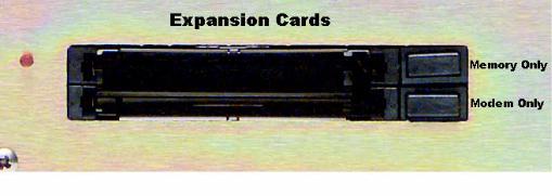
Before installing your Omnia-6EX, or even plugging in the power cord, make sure the Omnia-6EX PC Memory Card and Optional Modem Card (if purchased) are installed into the correct card slots on the back panel and are fully seated. Installation or removal must be done with the power off unless directed otherwise.
The PC Memory Card is inserted into the top card slot with the Omnia label facing up and the version number sticker facing down. The Optional Modem Card is inserted into the bottom card slot below the Omnia PC Card. Both the PC Card and the Modem Card are keyed to prevent improper insertion. Gently press the cards into the slots until the black release button, to the right of the card, pops out about 1/2” [12.70 mm]. This indicates the card is properly seated in the PCMCIA slot.
Omnia-6ex Use and Operation Manual – V: 1.20
16
The Omnia-6EX also contains a third PC Memory Card slot that is used to load software for the Front Panel. The slot is located under the top cover on the right-hand side of the Front Panel circuit board and is normally unoccupied. Please do not insert or remove any PCMCIA cards from this slot without the direct assistance of Telos / Omnia customer support. Make sure the AC power is off and disconnected from the unit before removing the top cover and removing or replacing a card.
Important Note 1: The PC Cards used in the Omnia-6EX are not generic PCMCIA cards that can be bought in any local computer store. They are cards that are specially qualified by Omnia specifically for this product. If you need a backup card, please contact Omnia Customer Support to purchase an additional card. Inserting a card of unknown origin risks damaging the Omnia, the cards, or both, and doing so will void your warranty!
Important Note 2: If you wish to operate the Omnia-6EX using a PCMCIA type modem, you must use the available modem card from Omnia. Other modem cards are NOT qualified for use at this time. We cannot provide technical support for any other modem card. External modems are a different case. Typically, any external Hayes compatible modem may be connected to the rear-panel serial port. See Chapter 6 for more details on the Modem and the Remote Control Software.
Note: The rear panel PCMCIA Memory Card must remain in the top slot unless you are prompted by the system to remove it. Randomly removing the PC Card without system instruction may cause unpredictable operation and PC Card data damage.
AC Environment
The Omnia-6EX subsystem is microcomputer-based. Therefore, it requires the same clean AC environment as any modern computer system does. Even though the Omnia-6 is equipped with quite robust internal AC input transient suppression, we recommend that external transient suppressers/voltage regulation or an Uninterruptible Power Supply (UPS) be employed. This recommendation becomes even more important when installing the processor at a transmitter site, where there can be heavy transients on the power lines. These unwelcome events can be caused by anything from load switching to lightning strikes on a nearby tower. Therefore, we ask that you give your AC power environment and installation practices thorough consideration before plugging in your Omnia6-HDFM unit.
Omnia-6ex Use and Operation Manual – V: 1.20
17

Installation & Connections
Throughout this section reference is made to “software parameters.” These are part of the Graphical User Interface, which is covered in detail in Chapter 2.
Rack Mounting
The Omnia-6EX requires 3RU (5.25” [37 mm]) of rack space. Rack mount the unit using four rack screws. If only two screws are going to be used, they should be in the bottom holes in the Omnia front panel. No other two-screw mounting arrangement will prevent distortion of the front panel casting! Adequate ventilation should be provided, and it is always good engineering practice to allow one blank rack space immediately above and below the Omnia, especially if equipment generating significant heat is located below the unit. Install a 1RU (1.75”) vented or solid panel to fill these spaces.
The processor should be installed into a thoroughly grounded 19” equipment rack. Refer to Chapter 4, “Processor Interfacing”, for additional considerations on where to physically locate your processor.
AC Connection (IEC)
The Omnia-6EX utilizes a heavily filtered, universal AC power-entry module. Its integral power switch is located just above the IEC power cord receptacle. The Omnia6-fm's voltage–sensing, switching power supply allows it to operate on AC mains voltages from 100 to 240 VAC, 50/60 Hz. In the USA, plug the provided IEC type AC power cord into the unit and then into a grounded AC outlet. Outside of the USA, you must use the appropriate power cord that complies with local electrical regulations.
Press the “I” side of the rear-panel power switch to turn on the unit. The Omnia-6EX is designed to be continuously powered, however, pressing the “O” side of the switch turns off the unit for servicing.
When power is first applied, it takes approximately ten seconds to load the DSP code from the rear-panel PCMCIA
Omnia-6ex Use and Operation Manual – V: 1.20
18
memory card. During system power-up, the front panel LCD screens display several status screens while the operating software and DSP code is loaded. Once the main Omnia-6EX Main Menu is shown on the right screen, and the Meter Screen is shown on the left display, the unit is ready for use.
Rear Panel Connections
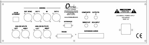
Audio Inputs—Analog & Digital (Female XLR)
Balanced XLR-type connectors are used as input connectors for both the analog and AES/EBU digital audio. Both analog and digital input sources may be connected simultaneously, however, only the input source that has been set in the Input menu is active. Analog/Digital Input source selection is done through the Input Source software parameter setting in the Input Menu.
The stereo analog inputs are designed for standard +4dBu balanced signals. Pin 2 is Hot. The digital AES/EBU inputs (IN and EXT. SYNC) accept any sampling rate between 32kHz and 96kHz. No user adjustment is necessary on the AES input since a high-quality sample rate converter is built into the unit. Individual channel gain and level setting for both analog and digital is done using the Input Gain software parameter settings in the Input Menu.
A Note About Relative Phase: If the relative phase of your installation (including the Omnia-6EX) differs from that of your existing system, your announcers may feel that they sound “weird” in their headphones. If this occurs, then the relative phase of the processor is 180 degrees from what your air talent is used to. To remedy this, you can either reverse the polarity of both of the analog inputs or change the Invert Both software parameter setting in the Omnia-6EX Input Menu.
Audio Outputs—Analog & Digital (Male XLR)
Individual Left and Right analog outputs are available on two male XLR jacks. There is also an AES/EBU digital output. (Two on EX and Exi units) They are user configured for the conventional FM channel and/or the HD Radio/DAB signal paths. The digital outputs provide selectable sampling rates. The analog output is derived from a D/A converter driven from whichever output path is desired, either FM or HD/DAB.
Note: Both the analog and digital AES/EBU outputs are always active and can be used simultaneously.
Composite Outputs (BNC) (FM Mode Only)
These two low impedance outputs (Composite 1 and Composite 2) are each capable of driving up to 100 feet of RG58A/U coax cable. The output levels are individually adjustable so the unit can operate as a “composite DA” to drive a variety of equipment. The output levels and other stereo generator settings are set through software parameters in the Encode menu. An internal jumper sets the output impedance to either 10 ohms (the factory setting) or 75 ohms. The default setting is appropriate for the vast majority of exciter connections. However, in the event a higher source impedance is required a jumper can be moved (one for each composite output) on the motherboard to
Omnia-6ex Use and Operation Manual – V: 1.20
19
change the source impedance to 75 ohms. For reference, J10 is for Composite #1, and J13 is for Composite #2.
19 kHz Sync Output (BNC) (FM Mode Only)
This TTL-level 19 kHz square wave output can be used as the reference signal for any SCA generator that operates at 57 kHz or other multiple of the 19 kHz pilot frequency. This Sync output is phase and frequency locked to the stereo pilot. When this signal is used to synchronize an external SCA or RDS generator, this locking assures that no difference frequencies exist which may cause intermodulation components between the pilot and the SCA signal.
SCA Input (BNC) (FM Mode Only)
Any SCA signal above 53 kHz can be added to the composite outputs of the Omnia-6EX by connecting the SCA signal to the SCA INPUT connector. The SCA signal is mixed in the analog domain directly into both composite outputs. A high-pass filter on the SCA input provides SCA to main-channel crosstalk protection. The SCA deviation level is controlled through the SCA Level software parameter in the Encode Menu.
Ethernet Connection
The Remote Control link for your Omnia6-HDFM can take several forms. Dial-up modem, RS-232 serial, and TCP/IP over 10BaseT and 100BaseT networks can be utilized. Using any of these options requires the Omnia-6 Remote Control application that can be downloaded from http://www.omniaaudio.com, the Omnia website. The setup and operation of the Remote Control software application is covered in detail in Chapter 6.
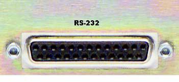
RS-232 Connection (DB-25F)
This connector serves two important purposes: It can be used for a local, bi-directional computer connection with Omnia-6 Remote Control, or it can be used for troubleshooting and error code resolution. In the former case, Omnia6-HDFM Remote Control software is utilized. In the latter, any terminal emulation program can be used. In either case, you must use a standard, straight-through serial cable (not a null modem cable) between the RS-232 connector and the serial port connector on the computer. Typically, a DB25 male to DB-9 or DB-25 female cable will be used, with the DB-25 male end of the cable attached to the Omnia-6EX.
The setup and operation of the Omnia Remote Control application is covered in detail in Chapter 6.
Omnia-6ex Use and Operation Manual – V: 1.20
20
Interface Connection (DB-9M)
This connector is the interface to the Omnia's internal trigger script function. Eight of the pins are “trigger” inputs and the remaining pin is the ground reference. The trigger inputs can be used to dynamically alter the Omnia-6fm’s operation in response to logic signal transitions at the interface connection. There is a unique response to each trigger input, that is, both “go-high” and “go-low” transitions are sensed. With eight inputs, and two sensed states for each one, sixteen unique 'trigger events' may be sensed to control the Omnia-6EXin response to these input logic transitions. Virtually ANY parameter of the Omnia can be controlled using the Trigger Scripts.
The Trigger Script Interface Editor is a standard component of the Omnia-6 Remote Control application and is covered in detail in Chapter 6.
Pin 1 Rear Panel Interface Connector for Remote Trigger Script Activation
The Pinout of the Omnia-6 rear-panel DB-9 Interface connector is as follows:
PIN 1 activates Trigger Script 1
PIN 2 activates Trigger Script 3
PIN 3 activates Trigger Script 8
PIN 4 activates Trigger Script 6
PIN 5 is connected to ground
PIN 6 activates Trigger Script 2
PIN 7 activates Trigger Script 4
PIN 8 activates Trigger Script 7
PIN 9 activates Trigger Script 5
Omnia-6ex Use and Operation Manual – V: 1.20
21
Powering Up
When the Omnia-6EX is first turned on, there is a few seconds of delay as the system starts up. You should notice a rectangular flashing cursor on the right screen followed by revolving Omnia logos on both screens, and then the main metering and menu screens should appear.
After approximately ten seconds from power-up, audio will be present from the analog, composite and headphone outputs. The AES/EBU outputs also become usable at this time. However, full initialization of the ports is not complete for several more seconds and there could be a brief, sub-second interruption while the AES/EBU IC’s configurations are being verified by the operating system. After 25 to 30 seconds, the Meter and Main Menu displays will appear on the left and right LCD screens respectively. At this point, the Omnia-6 is fully operational.
Omnia-6ex Use and Operation Manual – V: 1.20
22

Chapter-2: The Omnia 6 User Interface
Now that your Omnia-6EX is rack-mounted, connected to a program audio source, and turned on, you’re ready to learn how to operate it! This chapter covers the Graphical User Interface, your window into the Omnia-6EX processor.
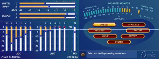
A front panel jog-wheel with integral push switch and twin Active-Matrix Color LCDs make up the Omnia-6EX Graphical User Interface. The right-hand screen is the “Menu Display”, and it shows the menus, submenus and useradjustable parameter settings. Also at the top of this screen is the world-renowned Dorrough© Loudness Meter, as implemented in Omnia DSP code. The left-hand screen serves as the “Meter Display”. It shows bargraph indications for the AGC and Limiter stages, as well as VU and 'digital sample accurate' peak indications of the Input and Output Levels.
Current Preset |
Time of Day |
Help Text Box |
“Home” Icon
The functions of the Menu Display can be selectively password protected from unauthorized processing or preset changes. The Meter Display dynamically indicates real-time signal processing activity, as well as the Input/Output levels. The backlights for the two displays are automatically turned off after a user set period of jog wheel inactivity, and the factory default timeout is 15 minutes. User options of 1, 5, 15 and 60 minutes turn-off times can be customized under the System menu.
Omnia-6ex Use and Operation Manual – V: 1.20
23
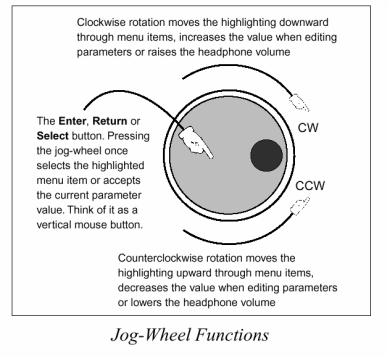
Using the Jog Wheel
The main user control for the Omnia-6EX is the large, easy to use jog wheel with its integral push-switch. Using the control is both intuitive, and efficient, making it easy to navigate the menu structure of the Omnia-6EX. Processing changes and system adjustments can be quickly made with ease without having to remember multiple controls, their positions, and what they do in each menu. The behavior of the Omnia-6EX's menu system is consistent across pages and is easy to learn. We believe that you will quickly become comfortable with how it works, and appreciate its simplicity.
See the diagram below to learn how each movement of the jog wheel affects the various menu options.
Omnia-6ex Use and Operation Manual – V: 1.20
24
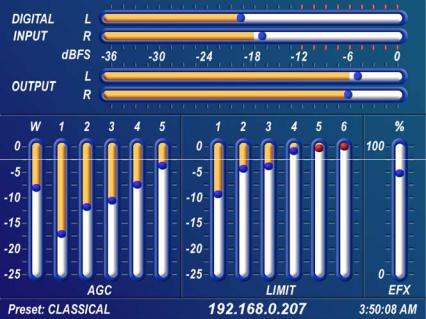
Level Meters & Processing Bargraphs
The horizontal meters show digital, sample-accurate, peak representations of the left and right input and output levels, while the vertical bargraphs show processing activity of the various algorithms. The currently selected Preset Name is displayed is the bottom left corner of the Meter Display, the currently entered IP address in the center and the current time is displayed in the lower right corner.
Left hand LCD screen showing I/O and process bargraphs
Audio I/O Level Display
The horizontal meters show the signal levels below full scale digital, (0 dBFS) which is the absolute maximum level in the digital domain. Both input and output levels are displayed in real time. The “bouncing balls” indicate sampleaccurate peak signal levels. In normal operation, the “bouncing balls” in the Input meters should regularly indicate between –12 and –6 dBFS. Since the meters are indicating the true peak level, this will give you about 20 dB of "VU" system headroom given typical (not hyper-compressed) program material. The Output meters indicate the peak levels at the analog and digital XLR outputs but not the composite MPX outputs.
Processing Display
The thirteen vertical bargraphs in the lower half of the Meter Display show the processing activity in real time within the Omnia-6EX. The first vertical meter (labeled W) represents the processing activity in the Wideband AGC section. The five vertical “AGC” meters show the processing activity of each of the AGCs in the multi-band AGC section. The six vertical “Limit” meters show the processing activity in each of the limiter sections of the multi-band limiter. Each of the meters is capable of indicating up to 25 dB of gain reduction.
The rightmost vertical bar graph (labeled EFX) indicates the processing level of the built-in Stereo Enhancement effect, when that function has been activated.
Note: The wideband AGC and Multi-band AGCs will recover to a resting gain setting which coincides with the RTP (Return To Platform) levels set for each band. Refer to Chapter 5, “Fine Tuning Your Sound”, for more information on interpreting and using the processing bargraph displays.
Omnia-6ex Use and Operation Manual – V: 1.20
25

Main Menu Display
The Omnia-6EX Main Menu is displayed on the right hand LCD screen, and offers seven menu selections: Preset, Schedule, Process, Encode, Input, Output and System. Below the Main Menu in the lower left corner of the display is a multipurpose “Help Text” box.
The Omnia-6EX menu system has been designed to be intuitive and simple to use, with a minimum of layered submenus. Most operating parameters are found on one of the seven main menus. This allows multiple processing changes to be made quickly and with ease.
When the Main Menu is displayed (as shown above), rotating the jog-wheel sequentially highlights each menu item. This is called Highlight Mode. With a menu item highlighted, pressing on the jog-wheel (called “clicking”) brings up that item’s submenu window. Similar action results when submenus are selected under these seven main menus.
The Preset menu item is shown highlighted in the Main Menu Screen illustration above. In this case, clicking the jog-wheel would open the Preset Menu window (shown at left). To exit a menu and move back to the main menu, highlight the “H” Home icon in the lower left corner, and click the jog-wheel.
“Home” Icon |
Preset Menu |
Omnia-6ex Use and Operation Manual – V: 1.20
26

In all menus with adjustable parameters, rotating the jog-wheel sequentially highlights each control or selection choice, along with the Home icon and the Headphone level button. In the Process menu, the parameter adjustment windows have an “X” Close Window icon in the upper right corner (as shown in the AGC Mixer window below). Highlighting this icon and clicking closes the window, returning the user to the Process menu, one level above.
“X”
Close Window Icon
AGC Mixer Submenu
To change the selection in a multiple-choice parameter, highlight the desired choice with the jog-wheel and click. A filled box serves to indicate that a parameter choice is selected.
To adjust a “rotary” knob control, like those shown in the AGC Mixer Parameter Window, highlight the control and click. The jog-wheel now functions as a rotary control. Rotating it clockwise adjusts the control up; counterclockwise adjusts the control down. The adjusted value is shown below the control. The original value is retained in a different color until the jog-wheel is clicked to make the new value permanent.
To cancel a control change, return the jog-wheel to the control’s original value. To apply a new level or value and return to Highlight Mode, just click the jog-wheel.
Omnia-6ex Use and Operation Manual – V: 1.20
27

Remote Control Session via Network Indicator
An exclamation mark inside a yellow triangle will show up in the lower left corner of the Main Menu screen when a Network remote session is in progress. A remotely connected network session has priority over local control of the front panel, so during a Network remote session the Main Menu will be grayed out. You may disconnect a Network remote session and regain front panel control by clicking the Disconnect remote button.
Omnia 6 Main Menu
The triangle with exclamation mark signifies that a TCP/IP Remote Control session is active.
Note: No front panel indication is shown when a serial or modem based remote control session is in progress!
Headphone Level Control
A standard ¼” stereo headphone jack located at the lower left corner of the front panel allows the processed signal to be monitored, and a Headphone volume level control is available in each submenu. When the headphone volume control slider is highlighted, clicking changes the jog-wheel into a headphone volume control. Once the headphone volume is adjusted to your liking, clicking the jog-wheel exits the volume adjustment mode, returning the jog-wheel back to Highlight Mode.
Note: The headphone amplifiers are fed from the same high quality, 24-bit D to A converter as the analog XLR outputs. Therefore, the overall Headphone volume will also be affected by the setting of the Peak Output Level controls in the Output Menu.
Omnia-6ex Use and Operation Manual – V: 1.20
28

User Interface Tutorial – Input Source Selection and Peak Input Level Setting
The following two exercises are a useful introduction to the user interface. Start from the Main Menu (as displayed when the unit is first turned on).
The first exercise changes a parameter selection (the Input Source selection):
1.Rotate the jog-wheel to highlight Input.
2.Click the jog-wheel (push on the wheel once) to bring up the Input window (shown below).
Input Source Select
Home Icon “H” |
Input Menu |
Headphone Level Control
3.Rotate the jog-wheel until one of the Input Source choices: Analog or AES/EBU is highlighted. The filled box next to the selection name identifies the current selection. The factory default selection for Input Source is Analog. To change the selection to AES/EBU, highlight AES/EBU and click. The AES/EBU box will now be filled and the digital input is now active. If you are using the analog inputs, highlight Analog and click to reselect the Analog inputs.
4.Rotate the jog-wheel until the Home icon “H” is highlighted in the lower left corner of the window. Click to return to the Main Menu.
5.Note that as you adjust the Input Source selection in this menu, the wording above the Input level bargraph on the Meter Screen changes to follow the selected source name.
Omnia-6ex Use and Operation Manual – V: 1.20
29

The next exercise adjusts a parameter that uses a value. (Input Gain)
This also serves as a tutorial on setting the proper input levels for optimum performance: For complete information on the controls in the Input Menu, see Pgs. 37-38.
1. Highlight Input and click to open the Input window.
Input Menu Showing Input Gain Controls
2.Rotate the jog-wheel to highlight Input Gain Master (Not Master Drive), and then click the jog-wheel to select the control.
3.Rotate the jog-wheel CW to increase the input gain. Rotate the jog-wheel CCW to decrease the input gain. This control adjusts both channels together so if your input source is unbalanced, watch the Left channel Input bargraph meter primarily when adjusting. The gain in dB is shown below the “control.” Note that the original setting is always shown in a different color when the control is adjusted. To cancel level changes, move the control back to the original setting and click.
Using normal program audio, a correct gain setting results in peak indications (the “bouncing balls”) regularly bouncing up to between -12 and –6 dBFS. Since the meters are indicating the true peak level, this will give you about 20 dB of "VU" system headroom given typical (not hyper-compressed) program material.
4.Once the desired gain is reached, click the jog-wheel to accept and use that value. This returns the jog-wheel to Highlight Mode.
5.Highlight and click Input Gain Right Trim and adjust it if the input source is unbalanced. It adjusts the gain of the right channel over a limited range of plus or minus 3 dB.
6.Rotate the jog-wheel until the “H”ome icon is highlighted. Click to return to the main menu.
All of the Omnia-6EX’s software parameters are set in a similar fashion using the jog-wheel in Highlight Mode to scroll through menu items and parameters. Clicking a highlighted item selects it; when that item is a control, the jogwheel adjusts the value or level. Clicking accepts the value or level and returns the jog-wheel to Highlight Mode.
Note: Changing any parameter value changes the Omnia-6EX’s audio output characteristics in real time so that all adjustments can be auditioned as they occur.
Omnia-6ex Use and Operation Manual – V: 1.20
30
Loading...