


Version 1.1
1 February, 2001
USERS MANUAL


Customer Service
We support you...
By phone/fax in the USA.
Customer service is available from 9:30 AM to 6:00 PM USA Eastern Time, Monday
through Friday at +1 (216) 241-7225. Fax: +1 (216) 241-4103.
By phone/Fax in Europe.
Service is available from Cutting Edge Europe in Germany at +49 81 61 42 467.
Fax: +49 81 61 42 402.
By E-Mail.
The address is: support@nogrunge.com.
Via World Wide Web.
The Cutting Edge Web site has a variety of information which may be useful for
product selection. The URL is: http://www.nogrunge.com.
Feedback
We welcome feedback on any aspect of the ToolVox
many good ideas from users have made their way into software revisions or new
products. Please contact us with your comments.
™
or this manual. In the past,
Cutting Edge
2101 Superior Avenue
Cleveland, OH 44114
USA
+1 (216) 241-3343
Fax: +1 (216) 241-4103
Updates
™
The operation of the ToolVox
is determined almost by software. A continuous
program of improvement is underway. Contact us to determine if a newer release is
available.
Trademarks
Cutting Edge, the Cutting Edge logo, Omnia and ToolVox are trademarks of TLS
Corporation. All other trademarks are property of their respective holders.
CUSTOMER SERVICE I

Copyright
Copyright © 1994-99 by TLS Corporation. Published by Cutting Edge, who reserves
the right to make improvements or changes in the products described in this manual,
which may affect the product specifications, or to revise the manual without notice.
All rights reserved.
Notice
All versions, claims of compatibility, trademarks, etc. of hardware and software
products not made by Cutting Edge mentioned in this manual or accompanying
material are informational only. Cutting Edge makes no endorsement of any
particular product for any purpose, nor claims any responsibility for operation or
accuracy.
Warranty
This product is covered by a one year limited warranty, the full text of which is
included in the Appendix of this manual.
Service
You must contact Cutting Edge before returning any equipment for factory service.
Cutting Edge will issue a Return Authorization number which must be written on
the exterior of your shipping container. Please do not return cables or accessories
unless specifically requested by Cutting Edge technical support. Be sure to
adequately insure your shipment for its replacement value. Packages without proper
authorization may be refused. USA customers: please contact Cutting Edge technical
support at +1 (216) 241-3343. All other customers should contact their local dealer to
make arrangements for service.
CUSTOMER SERVICE II

e
e
e
ee
Notices and Cautions
Notices and Cautions
Notices and CautionsNotices and Cautions
CAUTION:
THE INSTALLATION AND SERVICING INSTRUCTIONS IN THIS MANUAL ARE
FOR USE BY QUALIFIED PERSONNEL ONLY. TO AVOID ELECTRIC SHOCK, DO
NOT PERFORM ANY SERVICING OTHER THAN THAT CONTAINED IN THE
OPERATING INSTRUCTIONS UNLESS YOU ARE QUALIFIED TO DO SO. REFER
ALL SERVICING TO QUALIFIED PERSONNEL.
WARNING:
TO REDUCE THE RISK OF ELECTRICAL SHOCK, DO NOT EXPOSE THIS
PRODUCT TO RAIN OR MOISTURE. DO NOT SHOWER WITH THE UNIT.
THIS SYMBOL, WHEREVER IT APPEARS, ALERTS YOU TO THE PRESENCE OF
UNINSULATED, DANGEROUS VOLTAGE INSIDE THE CLOSURE - VOLTAGE
WHICH MAY BE SUFFICIENT TO CONSTITUTE A RISK OF SHOCK.
e
e
ee
w
w
ww
h
THIS SYMBOL, WHEREVER IT APPEARS, ALERTS YOU TO IMPORTANT
OPERATING INSTRUCTIONS.
THIS SYMBOL REFERS TO A HOT TIP. HOT TIPS ARE USEFUL BITS OF
INFORMATION THAT WILL HELP YOU GET THE MOST OUT OF YOUR
TOOLVOX.
CUSTOMER SERVICE III

TO PREVENT RISKS OF
ELECTRIC SHOCK,
DISCONNECT POWER
CORD BEFORE SERVICING
USA CLASS A COMPUTING DEVICE INFORMATION TO USER.
WARNING:
If it is not installed and used as directed by this manual, it may cause interference to
radio communication. This equipment complies with the limits for a Class A computing
device, as specified by FCC Rules, Part 15, Subpart J, which are designed to provide
reasonable protection against such interference when this type of equipment is operated
in a commercial environment. Operation of this equipment in a residential area is likely to
cause interference. If it does, the user will be required to eliminate the interference at the
user’s expense.
other devices are connected to this device without the use of shielded interconnect
cables. FCC rules require the use of only shielded cables.
This equipment generates, uses, and can radiate radio-frequency energy.
NOTE:
Objectionable interference to TV or radio reception can occur if
CANADA WARNING: “
This digital apparatus does not exceed the Class A limits for
radio noise emissions set out in the Radio Interference Regulations of the Canadian
Department of Communications.” “Le present appareil numerique n’emet pas de bruits
radioelectriques depassant les limites applicables aux appareils numeriques (de les
Class A) prescrites dans le Reglement sur le brouillage radioelectrique edicte par le
ministere des Communications du Canada.”
CUSTOMER SERVICE IV

Table of Contents
1 INTRODUCTION – WHAT IS THE TOOLVOX?...................................................1
2 INSTALLATION......................................................................................................3
3 QUICK SETUP GUIDE ...........................................................................................5
3.1 Powering Up...................................................................................................................................................... 5
3.2 Attaching Audio Cables .................................................................................................................................. 5
3.3 A Quick Look at the Front Panel................................................................................................................... 5
3.4 The Headphone Output .................................................................................................................................. 6
3.5 Installing the Remote Application Software ................................................................................................ 6
3.6 Connecting Your Computer to the ToolVox................................................................................................ 7
3.7 Creating a Connection to the ToolVox.......................................................................................................... 8
3.7.1 Serial connection ....................................................................................................................................... 9
3.7.2 Network connection .................................................................................................................................. 9
3.8 Adjusting the Audio Levels........................................................................................................................... 11
3.9 Let’s Begin Processing Some Audio ............................................................................................................ 11
3.10 Time to Become a Pro with ToolVox........................................................................................................... 12
4 THE FRONT PANEL ............................................................................................13
4.1 The LCD Screen and Edit Knob.................................................................................................................. 13
4.2 The Network LED.......................................................................................................................................... 14
4.3 The Phantom LED......................................................................................................................................... 14
4.4 LED Level Meter and Input / Output LEDs.............................................................................................. 14
4.5 Noise Gate LED.............................................................................................................................................. 14
4.6 De-esser LED .................................................................................................................................................. 15
4.7 Processing LED Bar graph........................................................................................................................... 15
4.8 Headphone Output and Control.................................................................................................................. 15
4.9 Setup Menu ..................................................................................................................................................... 16
TABLE OF CONTENTS V

5 THE REMOTE APPLICATION.............................................................................19
5.1 The File Menu................................................................................................................................................. 19
5.1.1 Open Preset.............................................................................................................................................. 19
5.1.2 Save Preset............................................................................................................................................... 20
5.1.3 Save Preset As ......................................................................................................................................... 20
5.1.4 Print Preset............................................................................................................................................... 20
5.1.5 Exit ........................................................................................................................................................... 20
5.2 The Options Menu ......................................................................................................................................... 21
5.2.1 Connect .................................................................................................................................................... 21
5.2.2 Disconnect................................................................................................................................................ 21
5.2.3 Edit Connection....................................................................................................................................... 22
5.2.4 Command Line........................................................................................................................................ 23
5.2.5 Preferences............................................................................................................................................... 24
5.3 The System Menu........................................................................................................................................... 25
5.3.1 Expert Edit Mode .................................................................................................................................... 25
5.3.2 Save System and I/O ............................................................................................................................... 25
5.3.3 I/O Configuration ....................................................................................................................................26
5.4 The Preset Menu ............................................................................................................................................ 28
5.4.1 Select........................................................................................................................................................ 28
5.4.2 Save Preset............................................................................................................................................... 28
5.4.3 Save Preset As ......................................................................................................................................... 29
5.5 The Help Menu............................................................................................................................................... 29
5.5.1 About........................................................................................................................................................ 29
5.5.2 Version…................................................................................................................................................. 29
5.6 The Processing Diagram ............................................................................................................................... 29
5.7 The Metering Screen ..................................................................................................................................... 30
5.7.1 Input Level............................................................................................................................................... 30
5.7.2 Output Level............................................................................................................................................ 30
5.7.3 AGC ......................................................................................................................................................... 31
5.7.4 Expander .................................................................................................................................................. 31
5.7.5 Compressor.............................................................................................................................................. 31
5.7.6 De-Esser................................................................................................................................................... 31
5.8 Advanced network parameters.................................................................................................................... 32
5.9 Security ............................................................................................................................................................ 33
6 THE AUDIO PROCESSING CHAIN IN DETAIL .................................................35
6.1 A Look at Audio Levels in the ToolVox...................................................................................................... 35
6.2 The Analog Limiter and Analog Level Control......................................................................................... 36
6.3 The Highpass Filter........................................................................................................................................ 38
6.4 The Phase Rotator.......................................................................................................................................... 38
TABLE OF CONTENTS VI

6.5 The Automatic Gain Control........................................................................................................................ 41
6.5.1 Manual or Automatic .............................................................................................................................. 41
6.5.2 Reference .................................................................................................................................................41
6.5.3 Attack and Release .................................................................................................................................. 42
6.5.4 The Freeze Gate....................................................................................................................................... 43
6.6 The Three Equalizers .................................................................................................................................... 44
6.6.1 Frequency................................................................................................................................................. 44
6.6.2 Gain.......................................................................................................................................................... 44
6.6.3 Q Factor ................................................................................................................................................... 45
6.6.4 Highpass................................................................................................................................................... 46
6.6.5 Lowpass ................................................................................................................................................... 47
6.6.6 Bandpass .................................................................................................................................................. 48
6.6.7 High Shelving.......................................................................................................................................... 49
6.6.8 Low Shelving........................................................................................................................................... 50
6.6.9 Peak.......................................................................................................................................................... 51
6.7 The Compressor ............................................................................................................................................. 52
6.7.1 Threshold .................................................................................................................................................52
6.7.2 Attack ....................................................................................................................................................... 52
6.7.3 Release ..................................................................................................................................................... 53
6.7.4 Ratio ......................................................................................................................................................... 53
6.7.5 Boost ........................................................................................................................................................53
6.8 The Expander .................................................................................................................................................55
6.8.1 Threshold .................................................................................................................................................55
6.8.2 Attack ....................................................................................................................................................... 55
6.8.3 Release ..................................................................................................................................................... 55
6.8.4 Ratio ......................................................................................................................................................... 55
6.9 The De-Esser................................................................................................................................................... 56
6.9.1 Threshold .................................................................................................................................................57
6.9.2 Max Reduction ........................................................................................................................................ 57
6.10 TrueVerb
6.11 Output Stage ................................................................................................................................................... 65
6.11.1 Panorama .................................................................................................................................................65
6.11.2 Gain Control ............................................................................................................................................ 65
®
by Waves..................................................................................................................................... 58
7 SPECIFICATIONS................................................................................................67
8 WARRANTY AND APPLICATION CAUTION ....................................................69
9 APPENDICES.......................................................................................................69
TABLE OF CONTENTS VII

TABLE OF CONTENTS VIII

TOOLVOX USERS MANUAL
1 Introduction – What is the ToolVox?
The Omnia ToolVox is a high-performance, all-digital voice processor designed to
work in concert with on-air broadcast or webcast processing to deliver a smooth yet
powerful voice presence. It integrates everything needed for voice into a single
system—including state-of-the art DSP reverb. The algorithms used in ToolVox
were born out of the extensive dynamics control developed for the Omnia broadcast
processor. ToolVox fully exploits the power of DSP to perform frequency domain
analysis while implementing the latest discoveries in speech psychoacoustics. An
example is its de-esser, which uses an advanced FFT method to predict and reduce
the sibilant energy that often causes excessive clipping in on-air processors. The
result is a voice sound that’s smooth, never grating and always powerful.
ToolVox includes:
• A studio reference-grade mic preamp with up to 70 dB of programmable gain and
built-in phantom power;
• 24-bit A/D and D/A converters for maximum digital fidelity;
• Slow gain-riding AGC with smart-freeze gate, compressor and noise gate sections,
designed with ratios and time-constants that work in concert with those found in onair and webcast processors;
• A phase rotator for reducing the amount of asymmetry in voice,
• Fully adjustable HP, LP and shelving filters plus parametric EQ; and
®
• TrueVerb, a powerful psychoacoustic room simulation program from Waves
.
Each ToolVox can store 100 presets that can be easily edited, moved or deleted as
®
required by the system administrator using the included Windows
Remote Control
application.
Presets can be manually selected from the front panel in a jock-friendly fashion:
Rotate a knob until the desired preset name is displayed, then press a button to load
the preset. Presets can also be remotely and automatically selected since ToolVox is a
network-ready processor. To prevent unauthorized tampering, ToolVox includes
built-in security features.
ToolVox includes both processed stereo analog and AES/EBU digital outputs as well
as an unprocessed output specifically designed for feeding telephone hybrids. An
AES/EBU Sync Input is included for those facilities using a master sample or house
clock.
A front panel volume control and stereo headphone jack are included for convenient
monitoring of the mic processing.
To help you get started, several factory presets are provided in each ToolVox–from
these starting points, we’re certain you’ll want to make your own.
Omnia, the promise of digital. . . delivered.
CHAPTER 1 1
INTRODUCTION

2 Installation
Analog Limiter Setting (Internal Switch)
Before rack mounting your ToolVox, determine if there is a need to defeat the builtin analog limiter that protects the A/D converter against short transient signal peaks.
We recommend that the limiter be left in the signal path. If your application requires
that the limiter be taken out of the signal path, you must take off the top cover on the
unit and set switch SW2 to position C2.
Rack Mounting
The Omnia ToolVox requires 1RU (1.75" (44.45 mm)) of rack space. If possible, try
to leave one empty space above the ToolVox to provide extra ventilation. If rack
space is available, add another empty space below the ToolVox.
ToolVox is normally placed in the studio or on-air control room where it can be
accessed by board-operators or on-air talent to select presets as required. There is no
danger of accidental preset “corruption,” since all preset programming is performed
through software running on a computer. The only controls on the unit are for
selecting and loading processing presets.
TOOLVOX USERS MANUAL
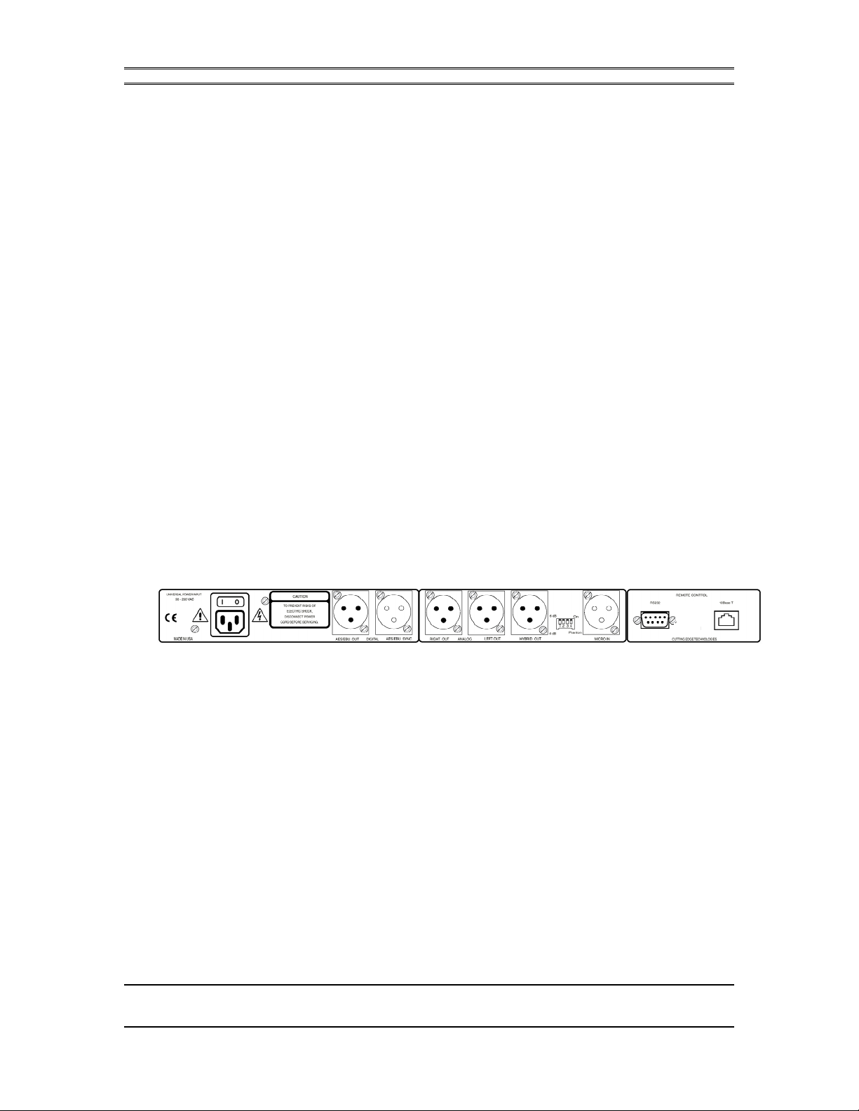
Rear Panel Connections & Controls
Power
The unit’s internal switching power supply can operate on 50 or 60 Hz power mains
supplying from 90 to 260 VAC. Plug the IEC power cord into the AC power entry
module on the rear of the unit. Turn on the power switch, also on the power entry
module.
DIP Switch (between MIC IN and HYBRID OUT)
The four position DIP switch is used to set installation parameters. At this time,
switches 1,2 and 3 are reserved for future options and are not used. Switch 4, when
set UP, turns on phantom power to the MIC IN connector. Circuitry in the ToolVox
actually confirms that 48 Volts is present before turning on the front panel
“Phantom” status LED.
RS232
CHAPTER 2 3
INSTALLATION

TOOLVOX USERS MANUAL
A 9-pin serial port connection for a local PC running the ToolVox Remote
application.
10Base-T
Ethernet network connector for connecting the ToolVox to a facility LAN. A single
computer, running the ToolVox applications, can control multiple ToolVox units
once each has been assigned a unique network address (TCP/IP). The Green LED
adjacent to the connector confirms a valid Ethernet connection, and the yellow LED
will flash during periods of network activity.
MIC IN (female XLR-type connector)
Any balanced dynamic or condenser microphone can be connected. If +48 Volt
phantom power is required, set DIP switch #4 (next to the MIC IN connector) to its
UP position. A front panel LED lights to indicate phantom power is switched on. If a
dynamic microphone is used set DIP switch #4 DOWN to turn off phantom power.
Level control is set using the ToolVox remote control application.
HYBRID OUT (male XLR-type connector)
A balanced +6 dBu mono output of the preamplified mic signal, designed for feeding
a telephone hybrid. This signal is extracted after the analog limiter. This analog feed
should connect directly to the SEND input of the telephone hybrid. Better hybrid
performance can be obtained by using unprocessed audio, so the HYBRID OUTPUT
is just a loopback of the analog input to the ToolVox.
ANALOG OUT (male XLR-type connector)
Stereo processed audio connections (LEFT OUT and RIGHT OUT) using standard
active balanced 50 Ohm outputs.
Connecting the ToolVox Output to Unbalanced Equipment
We urge you to always use balanced connections between equipment in a studio.
Connecting an unbalanced device in a very noisy environment might lead to noisy
audio signals. One possible way to improve signal quality in such a situation is to
ground one of the signal pins. ToolVox provides internal jumpers that allow pin 3 to
be grounded on the analog output connectors. [this should be repeated in the
installation section earlier before the customer puts the unit in the rack].
AES/EBU SYNC (female XLR-type connector)
Only used when a facility requires a house sample clock reference signal to
synchronize all digital devices. Connect using 110 ohm digital cable.
AES/EBU OUT (male XLR-type connector)
Stereo digital output of the processed microphone audio. Use 110 ohm digital cable
to route the output to a digital console or other AES/EBU-compatible device.
CHAPTER 2 4
INSTALLATION

3 Quick Setup Guide
3.1 Powering Up
As described in the previous section, apply AC via the IEC style connector on the
back of the unit. The power switch is located just above the power connector.
3.2 Attaching Audio Cables
The microphone should be connected to the Mic In female XLR connector. This
should be a balanced connection to reduce the effect of common-mode noise induced
in long cables. Adjust Dip-Switch 4 to the UP position when +48V Phantom Power
is required for your microphone.
For analog output, attach a female XLR cable to the Analog Out connector. The
analog output of the ToolVox is adjustable and has a 50 ohm source impedance. A
peak level of +15dBu is available.
TOOLVOX USERS MANUAL
For digital output, connect a female XLR cable to the AES/EBU OUT connector.
The Professional Mode AES/EBU format is used by the ToolVox. The output is
transformer isolated with 110 ohm source impedance (standard AES/EBU).
The HYBRID OUTPUT connector is provided for the broadcast facility which wants
to feed the output of the ToolVox into a call-in talk show system. This analog feed
should connect directly to the SEND input of the telephone hybrid. Better hybrid
performance can be obtained by using unprocessed audio, so the HYBRID OUTPUT
is just a loopback of the analog input to the ToolVox.
In many all-digital installations, an AES/EBU sync clock is used to synchronize all of
the equipment in a facility to a common sample rate. If your facility has such a
clock, the AES/EBU SYNC input connector should be used. This is also a standard
110 ohm AES/EBU connector.
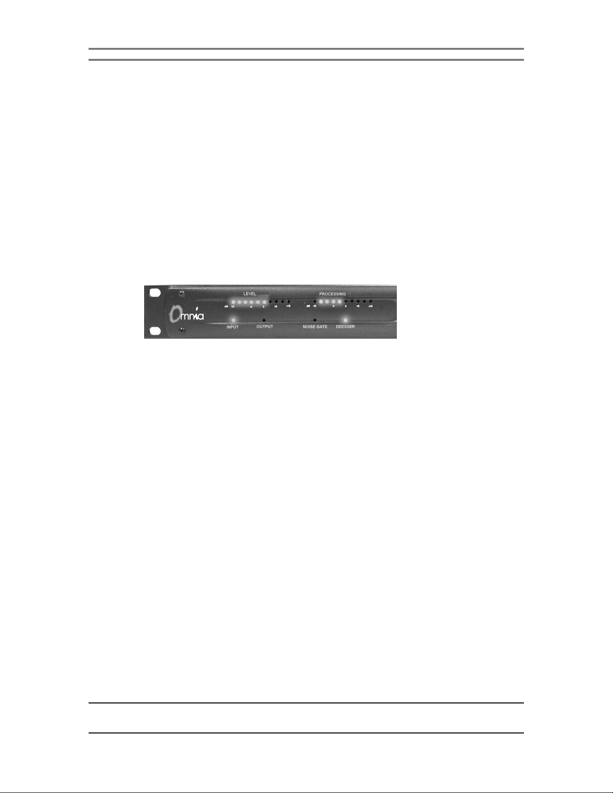
3.3 A Quick Look at the Front Panel
CHAPTER 3 5
QUICK SETUP GUIDE

Once your audio connectors have been made, power up the unit and check the front
panel indicators. You should see a preset name and number indicated on the front
panel LCD. Assuming you have no audio input, the PROCESSING meter should
indicate a gain of 0dB, and no level should be present on the LEVEL meter. The
INPUT and OUTPUT LEDs indicate the audio source for the LEVEL meter.
You can change the current preset by rotating the large knob to the right of the LED
screen. Select a preset by pressing the ENTER button.
3.4 The Headphone Output
A ¼” stereo jack is provided on the front panel for monitoring the ToolVox. The
headphone volume is controlled by the knob on the far right of the front panel.
TOOLVOX USERS MANUAL
w
listening to the headphone output.
3.5 Installing the Remote Application Software
Included with the ToolVox is a CDROM containing the ToolVox Remote
Application and additional information about the ToolVox. All of the features of the
ToolVox are accessible through this program, so before operating the processor this
application must be installed on a computer.
The Remote Application must be run on a Microsoft Windows compatible PC. Insert
the disk in your CDROM drive. Open Windows Explorer. Select the drive letter of
your CDROM drive and copy the REMOTE.EXE file from the SOFTWARE
subdirectory on the CDROM to your hard drive (a good location would be a
c:\ProgramFiles\Cutting Edge\ToolVox directory).
Start with the Headphone volume set to its lowest position before
CHAPTER 3 6
QUICK SETUP GUIDE

TOOLVOX USERS MANUAL
3.6 Connecting Your Computer to the ToolVox
The ToolVox must be connected to your computer by either of 2 methods:
•
Serial connection
Use the serial port on the back of your computer to link to the RS-232 port on the
ToolVox. Use the 9-pin serial cable included with the ToolVox, or use your own
serial cable. The RS-232 port on the ToolVox is a standard female DB9 connector
and can be attached to your computer’s DB9 or DB25 serial port using standard (nonnull modem) cables.
• TCP/IP Network Connection
Use a 10Base-T cable to connect the ToolVox to the local network. Also make sure
that the computer on which you will use the Remote Application software is
connected to the network.
h
If you use the serial port, make a note of which COM port to
which you have attached the serial cable, so you can configure
the Remote Application quickly and correctly.
CHAPTER 3 7
QUICK SETUP GUIDE
TOOLVOX USERS MANUAL
3.7 Creating a Connection to the ToolVox
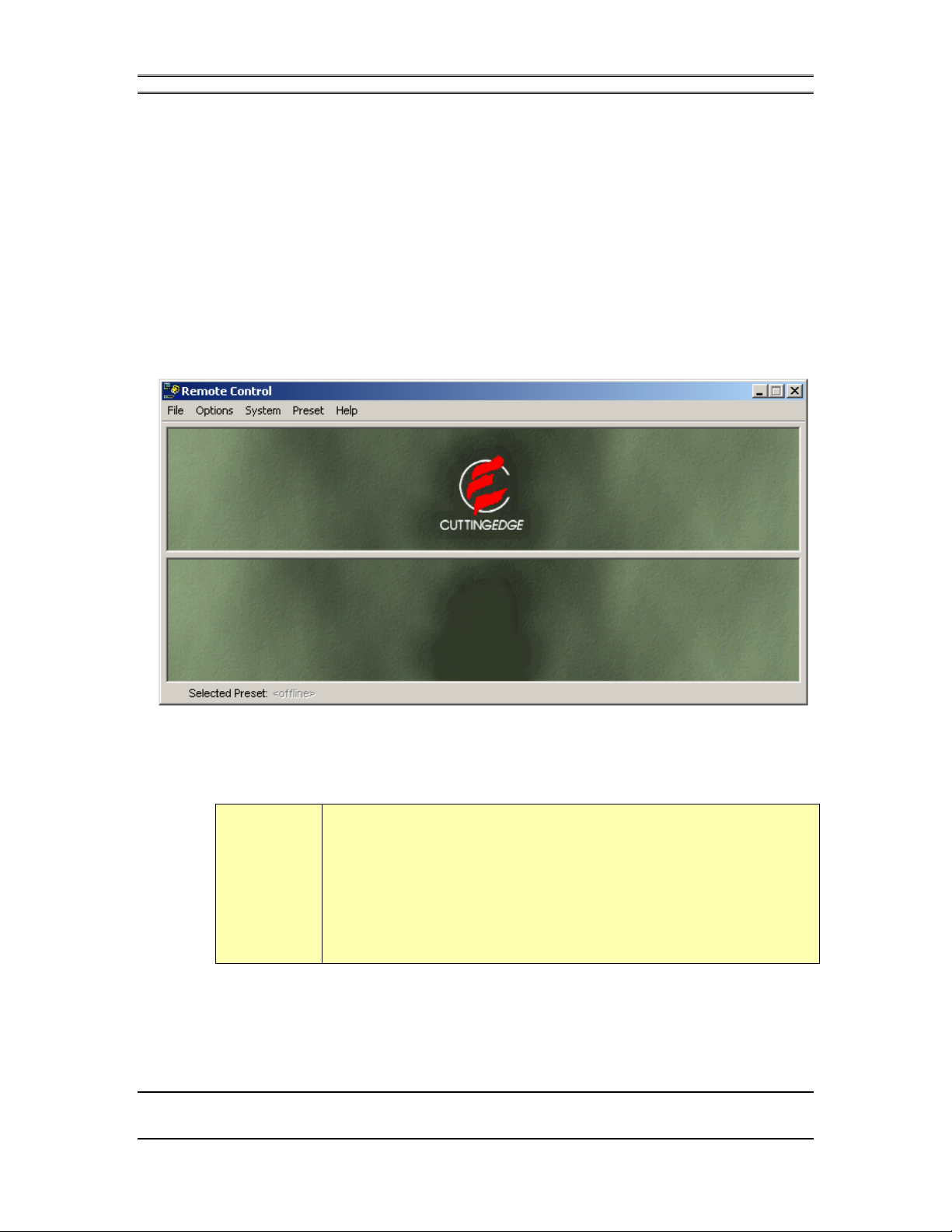
Now you’re ready to begin experiencing the power of ToolVox. Start the ToolVox
Remote Application by either choosing it from the Start Menu – Programs selection
tool, or double-clicking the program icon from Explorer. The window below appears:
The first time you use the program, you will see a warning
window appearing with the following message: ”No connection
database, creating database.” Press OK.
h
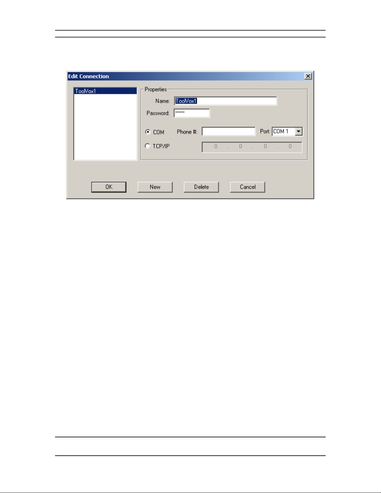
You must create and configure a Connection using the application software. Go to
the Options Menu and choose Edit Connection. The dialog box shown below will
appear and will allow you to enter the connection parameters.
CHAPTER 3 8
QUICK SETUP GUIDE
TOOLVOX USERS MANUAL
3.7.1 Serial connection
First, give your connection a meaningful name. Then, enter the ToolVox password
that gives you the level of control you want. For example, use the password “corli”;
this gives the highest level of access to the ToolVox features. A complete list of
passwords and access levels is provided in the Remote Application chapter of this
manual. Now choose the COM radio button to select the RS-232 type of connection.
Select the COM port you used when attaching the serial cable to the unit, and press
OK.
3.7.2 Network connection
• Remote Application settings
First, give your connection a meaningful name. Then, enter the ToolVox password
that gives you the level of control you want. For example, use the password “corli”;
this gives the highest level of access to the ToolVox features. A complete list of
passwords and access levels is provided in the Remote Application chapter of this
manual. Now choose the TCP/IP radio button to select the Network connection.
Enter the IP Address of the ToolVox you want to connect to, on the right of the radio
button, and press OK.
CHAPTER 3 9
QUICK SETUP GUIDE

For more details concerning advanced network parameter settings (gateway
and subnet mask), see chapter 5.8.
w
w
ww
• ToolVox Settings
In order to use the ToolVox through the network, you need to assign it an unique IP
Address (To obtain an available address on the network you are connecting the
ToolVox to, see your network administrator).
Once you get this address, set up the ToolVox by holding the ENTER button for at
least 3 seconds. You will then see the Setup Menu appearing on the LCD screen.
Press ENTER again to select the IP Address item. The first number of the IP
address will be blinking. Use the large Edit Knob to scroll up (to the right) or down
(to the left) through the numbers from 0 to 255. Then, press the ENTER button to
confirm and switch to the next number. Repeat this last action for the three other
numbers.
TOOLVOX USERS MANUAL
Once the four numbers building the IP address are set, the ToolVox will
automatically reboot. Now, the ToolVox is ready for a network connection.
During the manipulations in the ToolVox Setup Menu, if no
parameters are changed in the 20 seconds following the
last change, the ToolVox will automatically close the menu
and come back to the presets view.
w
CHAPTER 3 10
QUICK SETUP GUIDE

TOOLVOX USERS MANUAL
Now that you have created a Connection, you can use it to communicate with the
ToolVox. Under the Options menu select Connect and choose any connection from
the list box. Press OK or double-click on the name to activate the connection. After
a few moments you should see the ToolVox Processing Diagram and the meter
information appear on the screen as shown below. If this doesn’t happen you may
have chosen the wrong COM port or the wrong IP address in your connection
creation. You can use Options – Edit Connection to change the settings of the
connections should you need to.
3.8 Adjusting the Audio Levels
To calibrate audio levels, you will need to provide an audio source to the unit: your
own voice will do just fine. Go the System menu and select I/O Configuration. In
the dialog box, change the Front Panel Level Meter selection to Input. Press OK.
Test the microphone input level by speaking in a normal voice and watching the
input level meter. If it is not peaking between -10dB and +10dB, you should adjust
the analog input level. Click once on the Input box in the Processing block diagram
and adjust the Analog Input Level until the audio level peaks in the range cited above
when you speak.
If the input is slightly out of range, don’t panic. The powerful
AGC functions in the ToolVox will optimize your levels.
h
Now monitor your output with the headphone jack on the front panel. Adjust the
headphone volume to a comfortable level.
3.9 Let’s Begin Processing Some Audio
The heart of the ToolVox is the ability to create custom presets tailored to the
individual(s) whose voices need to be processed. The ToolVox can store up to 100
CHAPTER 3 11
QUICK SETUP GUIDE

TOOLVOX USERS MANUAL
presets in the unit’s memory. The factory presets which come with the unit can be
replaced with your own at any time. Choose a preset by selecting Preset – Select
from the drop down menus. The Remote Application will upload all of the presets
from the unit’s memory (this will take a moment). Choose a preset to edit from the
list. Don’t worry about overwriting the factory preset now; you won’t be saving this
preset unless you absolutely want to.
To edit a preset, use the Processing Diagram in the upper half of the application
window. The Processing Diagram is a graphical interface to the ToolVox processing
parameters. Select a box in the diagram by clicking on it once. A dialog box will
appear and display the parameters associated with that processing function. Try
selecting different boxes and become familiar with the parameters and their effects.
Notice that the dialog boxes that appear can be moved around the screen just like any
other window. This is useful for viewing several processing parameters at once, as
well as keeping the meters in view when you adjust the sound.
Change the LEVEL meters so that they indicate the output level of the ToolVox
analog output by selecting System – I/O Configuration from the drop-down menu.
Using the Output processing box you can change the output level to match your
facility’s optimal audio level. Keep in mind that this will also change the volume in
your headphones.
3.10 Time to Become a Pro with ToolVox
Now that you are familiar with the ToolVox editing environment you can completely
customize your audio with the advanced features of ToolVox. The rest of this manual
covers every aspect of the Remote Application, Processing Parameters. Take the time
to read through all of the sections – you will want to know the ToolVox inside and
out to get the most out of this revolutionary new product!
CHAPTER 3 12
QUICK SETUP GUIDE

TOOLVOX USERS MANUAL
4 The Front Panel
Because the ToolVox system is designed to work primarily with the Remote
Application software, the front panel of the ToolVox is somewhat spare, displaying
only the essential information needed to indicate proper operation and to select
presets.
4.1 The LCD Screen and Edit Knob
The LCD indicates the currently selected preset. Use the large Edit Knob to scroll
through the presets stored in the unit. Press the Enter button to select a new preset.
The LCD screen and Edit Knob also allow access to a SETUP MENU (see chapter
4.9).
The ToolVox remembers the last preset selected. You can
“double-click” the Enter button to do an A/B comparison of the
current preset and the last preset selected.
h
CHAPTER 4 13
THE FRONT PANEL
4.2 The Network LED
When the ToolVox is properly connected to a TCP/IP network, this LED will
illuminate.
4.3 The Phantom LED
This LED indicates the status of the 48V phantom power on the microphone input.
Phantom power is selected using Dip Switch 4 on the back panel of the ToolVox.
ToolVox actually monitors the Phantom Power voltage, so this LED will also help
you troubleshoot any problems you might have (such as turning Phantom Power on,
and not getting any).
TOOLVOX USERS MANUAL
4.4 LED Level Meter and Input / Output LEDs
The LED bar graph on the left side of the front panel can be configured to display
one of the following audio levels: input, analog output, or digital output. A range of
–15dB to +15dB is indicated on the bar graph, with each LED representing an
additional 3dB of level. The range from +3dB to +15dB is indicated by red warning
LEDs. 0dB refers to the unit’s analog reference level of –15dBFS.
The Input and Output LEDs indicate which level is displayed. Use the Remote
Control application to change the level meter function (under the System – I/O
Configuration drop-down menu). The LED meters indicate the RMS average level,
as well as the true peak level of the audio.
4.5 Noise Gate LED
This LED follows the operation of the Expander.When the audio level is below the
Expander threshold, the Noise Gate LED will illuminate.
CHAPTER 4 14
THE FRONT PANEL

TOOLVOX USERS MANUAL
4.6 De-esser LED
When the De-esser is operating, this LED will indicate when there is excessive
sibilance being removed from the audio signal. The De-esser is controlled from the
Remote Application, in the Processing Diagram.
4.7 Processing LED Bar graph
The Processing LED bar graph shows a composite of the control signals applied by
the AGC, Compressor, Expander and De-esser sections. When any one of the
functions is controlling the audio, the Processing bar graph will indicate the amount
of gain increase (0 to +15dB) or decrease (0 to –15dB) applied to the audio level.
If only the AGC section is turned on, the bar graph will only
display a control signal if the AGC is set to Automatic. The
Manual setting disables the display of the AGC control voltage.
h
4.8 Headphone Output and Control
The ¼” Stereo Headphone Jack on the right side of the front panel allows monitoring
of the Analog Output of the ToolVox. Adjusting the Analog Output in the Output
block of the Remote Application Processing Diagram will change the level in the
headphone monitor. The headphone volume is controlled by the knob to the right of
the headphone jack.
CHAPTER 4 15
THE FRONT PANEL

TOOLVOX USERS MANUAL
4.9 Setup Menu
On the ToolVox, a SETUP MENU is implemented. This menu is composed of three options.
•
IP Address : used to set up the ToolVox dedicated IP address.
• Reboot function: used to reboot the ToolVox.
• Exit: exit from the Setup Menu.
To access this menu, hold the ENTER key for 3 seconds. The Setup Menu appears
on the LCD screen with the first option on the second line(IP Address).
To select or change the IP address, press the ENTER key. You will see the first
number of the IP address blinking. Use the large Edit Knob to scroll up (to the right)
or down (to the left) through the numbers from 0 to 255. Then, press the ENTER
button to confirm and switch to the next number. Repeat this last action for the three
other numbers. Once the four numbers building the IP address are set, the ToolVox
will automatically reboot.
To reboot the ToolVox, go to the Setup Menu, select the Reboot option by scrolling
to the right one time. Then, press ENTER. The ToolVox will reboot.
To exit from the Setup Menu, scroll right (or left) using the large Edit Knob until you
find the Exit option. Then, press ENTER. The ToolVox will end up at the Setup
Menu without rebooting.
During the manipulations in the ToolVox Setup Menu, if no
parameters are changed in the 20 seconds following the
last change, the ToolVox will automatically close the menu
and come back to the presets view.
w
CHAPTER 4 16
THE FRONT PANEL

w
TOOLVOX USERS MANUAL
During the reboot function, be aware that you will loose all
the I/O and preset settings that you changed, unless you
have saved them.
CHAPTER 4 17
THE FRONT PANEL


TOOLVOX USERS MANUAL
5 The Remote Application
The installation of the Remote Application software was covered in the Quick setup
section.
5.1 The File Menu
The File menu allows you to Load and Save presets from/to your hard drive or
floppy disk, Print preset settings, and Exit the Program. Preset files (files with
extension PRS) are used to store presets on your computer for archiving and copying
to other ToolVox units in your facility.
5.1.1 Open Preset
Use this command to load preset files from your computer into the Remote
Application. The stored preset will be immediately activated as the current preset in
the ToolVox connected to your computer.
h
Preset files can be downloaded from the Cutting Edge web site,
as well as e-mailed to different facilities and copied to other
computers.
CHAPTER 5 19
THE REMOTE APPLICATION

5.1.2 Save Preset
After you Open a preset into the Remote Application, you can make changes to the
preset and then save it back to your computer using the same name by selecting Save
Preset from the File menu.
w
TOOLVOX USERS MANUAL
Using Save Preset will overwrite the existing preset on your
computer.
5.1.3 Save Preset As
Use Save Preset As to save the currently modified preset to your computer using a new name. The dialog box will ask you to specify the directory in which to save the preset file, as well as the name of the file.
5.1.4 Print Preset
Print Preset is a used for generating a hard copy of the entire preset. This is a useful technique to save your work in tangible form. In addition, there is the possibility that new software revisions of the ToolVox will be incompatible with your current presets. Printing the preset is a useful way of keeping the preset parameters handy in case you need to enter the preset should you receive an incompatible software version.
5.1.5 Exit
A nice way to quit out of the Remote Application.
CHAPTER 5 20
THE REMOTE APPLICATION

5.2 The Options Menu
5.2.1 Connect
Connect brings up the list of Connections stored on your computer (assuming you have created at least one). A list of the available connections will appear, allowing you to choose one and connect to the ToolVox. After choosing a connection, the Processing Diagram and Meter Screen should appear. If not, use Edit Connection to check the particulars of this connection and make the necessary changes. Also check your cabling and make sure the ToolVox is powered up.
TOOLVOX USERS MANUAL
h
5.2.2 Disconnect
Disconnect will immediately terminate any connection you have running. If there are multiple ToolVox units that you are configuring (on a LAN, for example), use Disconnect to drop the current connection and then Connect to the next ToolVox to be configured.
You can open more than one instance of the Remote
Application to connect to more than one ToolVox at a time.
This is particularly useful in LAN applications, but if you have
multiple ToolVox units connected to separate COM ports on
your computer, this will work as well.
CHAPTER 5 21
THE REMOTE APPLICATION

5.2.3 Edit Connection
Choosing Edit Connection brings up the following dialog box:
TOOLVOX USERS MANUAL
To make a new connection, select New. A default name will appear in the Name
box, and the other boxes will be set to their default settings. Change the name to
something meaningful (e.g. AirStudio). Enter the password (see Security in this
chapter) appropriate for this connection. Select either COM for a serial connection,
or TCP/IP for a LAN connection.
You are not required to enter the password when you create a
new Connection. The Remote Application will prompt you to
enter the password when you connect to the ToolVox. This is
useful for maintaining security on your computer.
h
For a COM connection, enter the phone number to dial (assuming you are using a
modem to configure the ToolVox), or simply choose the appropriate COM port for
this connection.
For a TCP/IP connection, enter the IP address for the ToolVox.
CHAPTER 5 22
THE REMOTE APPLICATION

To edit an existing connection, select that connection from the list box. The
parameters for that connection will be shown in the appropriate boxes. Make any
changes and then click OK to save them.
A new Connection should be created for each ToolVox in your facility which will be
connected to this computer.
5.2.4 Command Line
Command Line brings up the following window:
TOOLVOX USERS MANUAL
The command line is a very low level interface to the ToolVox operating system. If
you are having difficulty with the ToolVox, Cutting Edge Customer Service may
instruct you to open a Command Line interface to assisting in troubleshooting the
problem. There are a few other reasons to enter the Command Line which will be
covered later in the manual.
CHAPTER 5 23
THE REMOTE APPLICATION

5.2.5 Preferences
This screen allows you to customize the look and feel of the Remote Application
software.
TOOLVOX USERS MANUAL
Connect to Last Connected – When this box is checked, the Remote Application
will automatically connect to the last Connection used when you start up the
application. This is useful when you have your ToolVox on a LAN, or when you
leave it permanently connected to your computer’s serial port.
Decay Fade – When this box is checked, the level meters on the Remote Application
will visibly fade when the audio level is decaying.
Peak Indicator – The thin line on the Remote Application Level Meters that holds
the peak level can be turned on and off with this box.
Show as Solid Color – When checked, the 3-D appearance of the level meters will
be changed to a solid color.
CHAPTER 5 24
THE REMOTE APPLICATION

5.3 The System Menu
5.3.1 Expert Edit Mode
Currently not implemented.
5.3.2 Save System and I/O
TOOLVOX USERS MANUAL
This will immediately save the current I/O configuration (see I/O Configuration) to
the memory of the ToolVox. This prevents the ToolVox from reverting to the default
settings when you reboot the unit. This has no effect on presets or the audio
processing parameters.
CHAPTER 5 25
THE REMOTE APPLICATION

5.3.3 I/O Configuration
TOOLVOX USERS MANUAL
The I/O Parameters dialog box is divided into 2 parts: Appearance and Output.
Appearance parameters control the front panel of the ToolVox and what information
is displayed there. Output parameters control the source of the output audio as well as
AES/EBU Synchronization.
Front panel level meter has two choices: INPUT causes the LED bar graph to
display the level of the Input Audio (after the analog gain / limiting stage). OUTPUT
displays either the Digital Output level or the Analog Output level (selected by the
Output Meter selection).
Output METER allows you to display the DIGITAL or ANALOG output levels on
the level meters (both front panel and Remote Application).
Contrast selects among 3 choices for the LCD display contrast setting.
Backlight allows you to turn the LCD backlight on and off.
CHAPTER 5 26
THE REMOTE APPLICATION

TOOLVOX USERS MANUAL
Listen to selects the current audio processing parameters used to control the audio.
You can use this feature to do an A/B comparison of your current parameter settings
to those stored in the last selected preset within the ToolVox
When using the Listen to function, be aware that the Input Analog
Gain parameter is not considered a processing parameter. Thus, it
won’t change between the current state and the stored state.
w
Bypass all? Allows you to bypass the entire audio processing chain to listen to the
raw input audio. This is a good way to A/B the processed and unprocessed audio.
nd
2
channel source is a unique feature that gives you the ability to listen to the audio
removed by the de-esser in its analysis of the input audio. Selecting ANALYTIC
mode puts only the removed sibilance on the right channel output. This is a good
way to find out how much of the audio is being removed by the De-esser stage.
AES/EBU mode allows you force the AES/EBU output to synchronize to the
AES/EBU SYNC input source. The digital output will be sample-rate converted to
the recovered clock on the AES/EBU SYNC input.
Analog reference allows you to specify the output reference level for the analog
outputs. The gain (or cut) applied at this point will be based on the I/O reference
level of –15dBFS. This is explained in more detail in the Audio Processing section.
This setting is independent of the presets and should be set to optimize the output
level for your installation..
Digital reference allows you to specify the output reference level for the digital
output. The gain (or cut) applied at this point will be based on the I/O reference level
of –15dBFS. Again, this setting is independent of the presets.
CHAPTER 5 27
THE REMOTE APPLICATION

5.4 The Preset Menu
The Preset Menu gives you limited control over the presets stored in the connected
ToolVox. ToolVox has room for 100 presets in its internal memory. These presets
are all filled with factory presets when shipped. You can load any of the factory
presets, change them, and replace them using the Preset Menu. You can also load
your own presets and change them.
TOOLVOX USERS MANUAL
w
Note: The items in the Preset Menu affect presets stored in the ToolVox. This is in
contrast to the File Menu preset controls which modify presets on your computer.
5.4.1 Select
Select brings up a dialog box containing the list of all presets stored in the connected ToolVox. Clicking on one loads the selected preset.
5.4.2 Save Preset
Save Preset overwrites the current stored preset with the currently used set of processing parameters. The name of the preset will not be changed, but the stored preset will be lost (overwritten).
When you replace a preset inside the unit you will permanently
lose the old preset in that slot.
CHAPTER 5 28
THE REMOTE APPLICATION

5.4.3 Save Preset As
This choice allows you save the current preset under a new name. The old preset will
still be overwritten, as the same memory slot is used.
5.5 The Help Menu
5.5.1 About
The About screen displays pertinent information about the Remote Application, including the version number.
5.5.2 Version…
Version displays the software revisions of all software pieces in the connected
ToolVox.
TOOLVOX USERS MANUAL
5.6 The Processing Diagram
The Processing Diagram is the graphical user interface used to adjust the audio
processing parameters in the ToolVox. The Diagram is shown as a signal flow chain
to make it easy to visualize the effects and locations of the different processing
blocks.
CHAPTER 5 29
THE REMOTE APPLICATION

Clicking once on any block in the chain will bring up a dialog box containing the
processing parameters for that block. Each dialog box can than be dragged to any
location on the screen, and another processing block opened for editing. In this way,
you can modify several different processing blocks and listen to how they work in
concert.
Typically, you would begin editing a preset by starting with the blocks at the far left
of the chain. Calibrate your input levels, for example, using the INPUT block. The
PHASE ROTATOR is next because it doesn’t have any effect on the audio level.
The AGC, EQ, and COMPRESSOR / EXPANDER are next in order to optimize the
audio level for the more analytical blocks – the DE-ESSER and REVERB. Finally,
the OUTPUT block would be adjusted to give the correct analog or digital levels for
your installation.
The next chapter covers each audio processing block in very fine detail, including
tips on how to get the particular effect you might be looking for.
5.7 The Metering Screen
The bottom half of the Remote Application window contains the Metering Screen.
The screen displays the audio levels and control signals within the ToolVox in realtime; this makes it easy for you to adjust each processing block and immediately see
the effect (if any) on the audio.
TOOLVOX USERS MANUAL
5.7.1 Input Level
The left-most meter displays the level of the audio input, after the analog limiter and
analog gain stage. Use this level indicator to ensure you are running your input at an
optimum level: that is, not so low that the noise floor will become a problem, and not
so high that you run out of headroom. A level indication of -10 to +10 dB is ideal at
this stage of the audio chain (the AGC and Compressor / Expander will fine tune the
level later). Note that the Input and Output levels on the remote do not indicate the
true Peak (like the LED meters), but rather show the peak of the RMS value (this was
done because of the sluggishness of the Windows interface).
5.7.2 Output Level
The output level meter shows either the digital or the analog output level (each can be
run at different gains). Choose the level to be displayed by using the System – I/O
Configuration drop-down menu. Each installation will have a different optimal
output level: use this meter to adjust yours.
CHAPTER 5 30
THE REMOTE APPLICATION

h
5.7.3 AGC
The AGC meter displays the amount of boost or cut (attenuation) applied to the
audio in order to maintain a constant level throughout the unit. The THRESH
symbol illuminates when the audio is below the freeze threshold. This means that
the freeze gate is active. In other words, the audio level is so quiet that the AGC will
not respond; this is useful to keep the AGC from trying to bring up the level of what
is perceived as noise. When the audio level comes back up above the freeze
threshold, the AGC will take over and begin controlling the audio level again.
TOOLVOX USERS MANUAL
Note that the output level is in stereo, while the input is mono.
This is because the TrueVerb processing generates a stereo
reverb signal.
5.7.4 Expander
The Expander meter displays the amount of attenuation applied to the audio signal during quiet passages. The THRESH symbol will illuminate when the audio is below the selected threshold and the expander is working to attenuate the noise (thereby expanding the dynamic range of the audio).
5.7.5 Compressor
The Compressor displays the amount of attenuation applied to the audio during louder passages (to compress the dynamic range of the audio signal). The THRESH symbol will illuminate when the audio level is above the selected compressor threshold and the compressor is operating to reduce the level.
5.7.6 De-Esser
The De-esser meter displays the amount of attenuation applied to the audio during periods of sibilance (when the De-Esser Threshold is exceeded). Notice that the attack and release times of the de-esser are much faster than the other control signals because the goal of the de-esser is to only remove sibilants and leave the rest of the audio unchanged.
CHAPTER 5 31
THE REMOTE APPLICATION

TOOLVOX USERS MANUAL
5.8 Advanced network parameters
In a network configuration the two following advanced parameters other than the IP
address need to be set up on the ToolVox:
• Gateway* (also called IP router): this parameter represents the IP address of
the router that allows the ToolVox to be accessed from outside of the local
network.
• Subnet mask*: this parameter depends on the Class type (A, B or C) of the
network, which the ToolVox is connected to.
*To obtain these parameters, see your network administrator.
To set up the Gateway and subnet mask parameters, you need to use the Command
line interface (see chapter 5.2.4) of the remote application by opening OPTIONS
menu and selecting Command Line.
Once the window is opened, use the Edit command window to perform the following
commands:
• setgateway <Gateway address>: (ex: setgateway 192.160.0.145). If the
address is correctly entered, you will see the following message appear in
the Messages window: IP Gateway set to [Gateway address].
• setmask <subnet mask>: (ex: setmask 255.255.255.0). If the number is
correctly entered, you will see the following message appear in the
Messages window: IP network mask set to [Subnet mask].
• netinfo: this command displays a summary of the network settings: IP
address, gateway and subnet mask.
• Setip <IP address>: (ex: setip 192.160.0.123). It is also possible to change
the dedicated IP address of the ToolVox from the remote application.
If you change the dedicated IP address of the ToolVox from
the remote application, be aware that you will loose the current
connection (even if you are connected through the serial port)
and that the ToolVox will reboot automatically.
During the reboot function, be aware that you will loose all the
I/O and preset settings that you changed, unless you have
w
saved them.
CHAPTER 5 32
THE REMOTE APPLICATION

5.9 Security
The ToolVox Remote Application allows you to maintain a degree of security with
regard to who can edit presets, and the degree to which each user can alter the
settings. Use the following list of passwords and security levels when giving access
to users:
Password Access
None None
“noac” Reserved for future use
“susa” User level: View settings, select presets
“corli” Administrator level: alter presets, save
TOOLVOX USERS MANUAL
presets
To change the passwords you must bring up the Command Line window (under the
Options menu). Type in the following command:
>> passwd <oldpassword> <new password> <new password>
The new password is entered twice for your protection.
CHAPTER 5 33
THE REMOTE APPLICATION


TOOLVOX USERS MANUAL
6 The Audio Processing Chain in Detail
The audio processing in the ToolVox is incredibly sophisticated. This chapter will
explain in a high level of detail each of the pieces of the ToolVox processing chain.
This will allow you to have greater control in your attempts to create the “perfect”
sound for your application.
6.1 A Look at Audio Levels in the ToolVox
From the first analog input stage to the final output stage, the ToolVox maintains
several different reference levels that must be understood to fully utilize the different
algorithms in the processing chain. It will also allow you to maintain the highest
audio quality (measured by signal-to-noise ratio and harmonic distortion). The
following diagram illustrates how the peak and reference levels shift through the
different stages of processing.
The analog input section expects a nominal level of 0dBu, with a peak level of
+22dBu. This can be attained by appropriately choosing the analog gain setting in
the Input processing block. The analog limiter in the microphone preamplifier will
limit the input audio to a peak level of +15dBu (the maximum input level of the A/D
converter). The limiter has a “soft knee” and will actually begin applying control
CHAPTER 6 35
THE AUDIO PROCESSING CHAIN

TOOLVOX USERS MANUAL
when the audio level exceeds 0dBu. The amount of control will increase as the audio
level increases.
After the A/D converter, the +15dBu peak level will become 0dBFS (the maximum
audio level that can be represented in the digital domain). The 0dBu analog reference
level will be represented by –15dBFS (referred to as the I/O reference level).
Before the AGC block, the audio level is reduced by 10dB. The ToolVox has an
internal reference level of –25dBFS, which will hereafter be simply referred to as
0dB. All thresholds in the processing chain will be referenced to this level. For
example, setting the AGC Reference level to –5dB, will actually mean –30dBFS.
The reason for the– 25dBFS reference is to maintain adequate headroom for each of
the processing blocks. The noise floor in the DSP is less than –140dB, so this low
reference level will not affect the audio performance.
The AGC will attempt to keep the audio level at 0dB, assuming an AGC reference
level of 0dB.
The internal reference level is changed at the end of the processing chain to more
closely match the I/O reference of –15dBFS. The reference level in the ToolVox
processing chain is much lower than the A/D and D/A reference levels to provide
headroom for processing. The reference correction at the end of the chain will
depend on the Processing Parameters (Preset-based). The output level is adjustable
(for both the analog and digital outputs) to provide the right levels for your particular
installation. This Output Level Adjustment is tied to the ToolVox (independent of
presets).
Keep these levels in mind as you make adjustments to the audio chain; this way you
can avoid clipping the audio at the different stages in the processing.
6.2 The Analog Limiter and Analog Level Control
The ToolVox analog input section has 4 discrete gain settings that can be selected:
0dB, +20dB, +40dB, and +60dB. This allows ToolVox to work with a wide range of
CHAPTER 6 36
THE AUDIO PROCESSING CHAIN

TOOLVOX USERS MANUAL
microphones, and even line levels. Choose a gain setting for your particular
microphone that produces, during normal speech, a level of approximately –10 to
+10dB as viewed on the level meters.
In addition to gain programming in the analog section, there is also a limiter. This
limiter is designed to reduce peak levels on the microphone input in order to
maximize the headroom of the input audio. The limiter will apply a maximum of
7dB of gain reduction when the input audio exceeds the limiter threshold of +15dBu.
The limiter has a “soft knee,” so different amounts of gain reduction will be applied
depending on the audio level. This has the effect of allowing the input to be 7dB
hotter when applied to the A/D converter (in effect adding 7dB of headroom).
The limiter can be removed from the input circuit, although this is not recommended.
To disable the limiter, turn off the ToolVox remove the lid, and set switch SW2 to
position C2.
The following graph illustrates the input/output characteristics of the analog limiter in
the ToolVox.
CHAPTER 6 37
THE AUDIO PROCESSING CHAIN

6.3 The Highpass Filter
The Highpass Filter is designed to reduce rumble, wind noise, and other low
frequency sounds not normally associated with voice-band audio. Use the slide bar
to adjust the cutoff frequency of the filter from 20Hz to 100Hz, depending on the
frequency content of the audio you want eliminated. The filter can be disabled using
the On/Off box.
TOOLVOX USERS MANUAL
6.4 The Phase Rotator
The Phase Rotator can be turned on and off, and the amount of phase rotation (1
being the least, and 5 the most) can be adjusted in the Phase Rotator processing
block.
The Phase Rotator is an all-pass filter (meaning no attenuation of the signal at any
frequency) with a specific phase response designed to eliminate the asymmetry
commonly found in speech. Typical speech waveforms are such that the signal
amplitude is often greater on one side of the amplitude axis than the other. When an
asymmetric signal is clipped, the results are far more unpleasant to the ear than
symmetric clipping. Since clipping is often used in broadcast audio processing, a
phase rotator is a useful tool in a microphone processor.
CHAPTER 6 38
THE AUDIO PROCESSING CHAIN

TOOLVOX USERS MANUAL
The following figures demonstrate the effect of a phase rotator on an asymmetric
audio waveform. The left-hand figures are (in descending order):
1) An asymmetric waveform consisting of the sum of two sine waves of
different amplitude, phase and frequency.
2) One of the sine waves
3) The other sine wave (higher frequency with a phase shift)
In the right column, the resulting signals are shown after the original audio is passed
through the phase rotator. The dotted lines in the top picture indicate a possible clip
threshold; you can see the difference in the symmetry of the clipped audio. The
bottom sine wave has been phase shifted with respect to the upper waveform. The
reason for this is shown below.
CHAPTER 6 39
THE AUDIO PROCESSING CHAIN

TOOLVOX USERS MANUAL
The 3 graphs show the magnitude response, phase response, and group delay of a
phase rotator. The top graph shows that no gain or attenuation of the audio occurs at
any frequency. The third diagram is the most important indicator of the efficacy of a
a phase rotator. The group delay of a filter shows the amount of time delay applied
to different frequency components in a signal. A phase linear filter would show a
constant group delay, meaning no frequency component would be delayed with
respect to another. The phase rotator group delay curve shows that there is a
significant difference in group delay at low frequencies, but a constant delay at
higher frequencies. It is the changing group delay in the lower bands that remove the
asymmetry in audio by time-shifting the audio in those bands.
The 5 level settings affect the frequency at which the group delay curve begins to
level out. The higher the level setting, the higher the frequency where the curve
begins to flatten. In effect, the higher level settings will apply phase rotations to a
larger portion of the audio spectrum. The chosen setting will depend heavily on the
speaker and microphone selection. Generally speaking, the more asymmetric the
audio signal, the higher you should set the phase rotator level.
CHAPTER 6 40
THE AUDIO PROCESSING CHAIN

TOOLVOX USERS MANUAL
6.5 The Automatic Gain Control
The purpose of the Automatic Gain Control in the ToolVox is to maintain a
constant audio level inside the processing chain (refer to the section on Audio Levels
in the ToolVox for details). The AGC can apply gain or attenuation to the audio
depending on the level going into the block, and the threshold (reference level) you
choose.
6.5.1 Manual or Automatic
The first field in the dialog box allows you to set the gain control to Automatic or
Manual. The Manual setting forces a constant gain (or cut) to be applied to the
audio, regardless of the input level. Use the Manual Gain Setting slider at the bottom
of the dialog box to set the amount of gain you want. Using Manual effectively
bypasses all of the settings in the dialog box. Typically, you would use the
Automatic setting, as the amount of gain applied is a function of the input audio and
will more accurately control the audio level in the ToolVox.
6.5.2 Reference
This slider allows you to adjust the target level for the AGC. This is the audio level
that the AGC will attempt to maintain, regardless of the input level. The levels
shown on the slider are relative to the –25dBFS nominal level in the ToolVox. For
example, a reference level setting of -5dB on the slider will cause the AGC to
maintain an audio level of –30dBFS in the processor (-25dBFS + -5dB).
The higher settings will result in louder audio at the expense of headroom; lower
settings maximize headroom (allowing you to boost the audio more in the equalizer)
while bringing the audio level closer to the noise floor.
CHAPTER 6 41
THE AUDIO PROCESSING CHAIN

6.5.3 Attack and Release
The Attack and Release sliders allow you to control how quickly the AGC control
signal will respond to changes in audio level. Move the slider to the left for fast
response (up to 500mS), and to the right for the slowest (20 seconds). These times
refer to the time constant of the filter applied to the control signal. The following
example demonstrates this.
Here, an audio waveform is applied to the AGC. In this example, the numbers are
chosen simply to illustrate the effect of AGC and are not related to the actual
ToolVox levels and time constants. The audio begins with a peak amplitude of 0.5,
but suddenly increases to an amplitude of 1.0, and then drops to an amplitude of 0.25.
The AGC reference level is set to 0.5, the Attack time to 1mS, and the Release time
to 0.5mS. As you can see, when the audio level is exactly at the reference level, there
is no control applied to the audio (control signal = 0dB). But, when the audio level
increases above the threshold of 0.5, the control signal immediately begins to try and
reduce the audio level – finally reaching a stable point of –6dB (one half). The
Attack time controls how quickly the AGC will reduce the gain. When the audio
level drops below the 0.5 reference, the AGC applies a positive control signal to the
audio and brings the level back up – reaching a stable point of +6db. The Release
time controls how quickly the AGC will increase the gain.
TOOLVOX USERS MANUAL
CHAPTER 6 42
THE AUDIO PROCESSING CHAIN

TOOLVOX USERS MANUAL
AGC Control (Attack = 1.0mS, Release = 0.5mS)
1
0.8
0.6
0.4
0.2
0
-0.2
-0.4
Signal Amplitude
-0.6
-0.8
-1
Original Audio
Control Signal (dB)
0.006 0.012
Time (S)
8
6
4
2
0
-2
Control Signal (dB)
-4
-6
-8
Fast Attack and Release times can be useful for creating a very uniform output level,
but may cause an unpleasant “sea-sickness” effect on the listener, as the level is
constantly riding up and down. The slower time constants will reduce the audible
artifacts of the AGC, but will obviously do less to keep the level uniformly constant.
6.5.4 The Freeze Gate
One of the inherent problems with a typical AGC is that when the audio level drops
very low (during pauses or periods of silence), the AGC will increase the gain to its
maximum. When the audio resumes, the huge boost will cause the audio to be
incredibly loud, and often clipped. For this reason, the ToolVox includes a Freeze
Gate as part of the AGC section. The Freeze Gate, during periods of low level, will
cause the AGC to hold the control signal level until the input audio exceeds the gate
threshold. This gate threshold is set by the Freeze Gate slider (from –28dB to
+10dB).
A high freeze threshold is good for speakers who maintain a constant level, but for
dynamic speakers, a high threshold will not adequately boost the level during quiet
speech periods. A low threshold is much better in that case, because it will not
CHAPTER 6 43
THE AUDIO PROCESSING CHAIN

disturb the normal speech, but will still prevent the AGC from boosting the noise
floor, and then distorting the normal audio.
6.6 The Three Equalizers
TOOLVOX USERS MANUAL
There are three filters that can be activated to equalize the audio. Each filter has a
separate On/Off setting, and each can be configured to one of six different filter
styles. In addition, each filter style has one or more configurable parameters to fully
customize the effect of the filter.
6.6.1 Frequency
This slider changes the cutoff frequency for the Highpass and Lowpass filters. In the
case of the High Shelving and Low Shelving filters, the slider controls the point at
which the boost or cut will start being applied. For Bandpass and Peak filters, the
Frequency adjustment changes the center frequency of the filter.
6.6.2 Gain
The Gain slider applies the specified boost or cut to the Peak, High Shelving and
Low Shelving filters. Gain has no effect on the Highpass, Lowpass and Bandpass
filters.
CHAPTER 6 44
THE AUDIO PROCESSING CHAIN

6.6.3 Q Factor
The Q factor alters the width of the Bandpass and Peak filters. High Q produces a
very narrow width, while low Q causes a wide spread. Q Factor has no effect on the
other filter types.
h
TOOLVOX USERS MANUAL
A note on the use of the different filters: A common
misconception among users attempting to “fix” their
sound is to constantly boost certain frequencies. A
better technique in certain cases is to cut the audio
level in a frequency range. For example, a user who
complains that their audio signal sounds “muddy”
will usually boost the high frequencies with a highshelving filter. This only serves to partially mask the
problem. A better solution would be to cut out the
troublesome low end with the low-shelving filter.
This will reduce the amount of energy in the lowend, rather than push the whole audio signal closer
to the clip-point, and possibly run into trouble later in
the chain.
CHAPTER 6 45
THE AUDIO PROCESSING CHAIN

6.6.4 Highpass
Parameters: Cutoff Frequency (100Hz to 18kHz)
TOOLVOX USERS MANUAL
The Highpass filter is a second order filter with a rolloff of 12dB per octave. The
pass band has a gain of 0dB. The adjustable Highpass filter can be used to achieve
different audio effects, but would not normally be used in the chain (except with a
very low cutoff frequency to remove out of band ambient noise).
CHAPTER 6 46
THE AUDIO PROCESSING CHAIN

6.6.5 Lowpass
Parameters: Cutoff Frequency (100Hz to 18kHz)
TOOLVOX USERS MANUAL
The Lowpass filter is a second order filter with a rolloff of 12dB per octave. The
pass band has a gain of 0dB. The lowpass filter is similar to the highpass in that it
can be used as an effect or to cut out unwanted signals, but would not normally be in
the chain.
CHAPTER 6 47
THE AUDIO PROCESSING CHAIN

6.6.6 Bandpass
Parameters: Center Frequency (100Hz to 18kHz)
TOOLVOX USERS MANUAL
Q Factor (0.25 to 10)
Use the Q factor to adjust the width of the pass band. The pass band has a gain of
0dB. The bandpass filter is an excellent way to simulate certain audio conditions,
such as a telephone call or loudspeaker system (with large Q factors) or to isolate the
speaker’s audio from ambience (with small Q factors).
Tip: compare this filter with the Peak filter described below.
CHAPTER 6 48
THE AUDIO PROCESSING CHAIN

6.6.7 High Shelving
Parameters: Cutoff frequency (100Hz to 18kHz)
Gain (-15dB to +15dB)
TOOLVOX USERS MANUAL
The shelving filter acts like a treble control with adjustable cutoff frequency:
boosting or cutting the high frequencies while not affecting the low frequencies. The
figure shows 8 High Shelving Filters with a cutoff frequency of 5000Hz and different
gain settings.
CHAPTER 6 49
THE AUDIO PROCESSING CHAIN

6.6.8 Low Shelving
Parameters: Cutoff frequency (100Hz to 18kHz)
Gain (-15dB to +15dB)
TOOLVOX USERS MANUAL
The shelving filter acts like a bass control with adjustable cutoff frequency: boosting
or cutting the low frequencies while not affecting the high frequencies. The figure
shows 8 Low Shelving Filters with a frequency of 500Hz and different gain settings.
CHAPTER 6 50
THE AUDIO PROCESSING CHAIN

6.6.9 Peak
Parameters: Center frequency (100Hz to 18kHz)
TOOLVOX USERS MANUAL
Gain (-15dB to +15dB)
Q Factor (0.25 to 10)
The peak filter boosts or cuts the level for a specific frequency range. Use the Q
Factor to control the width of the frequency range. The above figure shows 8 Peak
Filters, each with a center frequency of 800Hz, a gain (or cut) of 10dB, and 4
different Q Factors. The peak filter is similar to the bandpass filter, except that it can
be used to boost or cut frequencies in the pass band (whereas the band pass filter only
removes frequencies outside the pass band). Interesting effects can be achieved with
a high-Q peak filter and some boost.
CHAPTER 6 51
THE AUDIO PROCESSING CHAIN

6.7 The Compressor
TOOLVOX USERS MANUAL
The Compressor is used to increase the density of the audio signal by reducing the
level of the audio above a certain, adjustable, threshold. While the AGC slowly rides
the gain of the audio up and down to keep a constant level, the Compressor
intentionally decreases the level of audio that exceeds the chosen Threshold, and then
applies gain to the entire signal. This has the effect of compressing the dynamic
range of the audio, giving a more controlled, tighter feel to the processed audio.
6.7.1 Threshold
The Threshold setting specifies the audio level at which the compressor will begin
applying gain reduction. A low threshold will dramatically reduce the dynamic range
(because it will cause the compressor to operate more often) but should be used with
caution as it will reduce the naturalness of the speech.
6.7.2 Attack
The Attack setting adjusts how quickly the control signal will attenuate a rise in input
audio level. A fast attack is useful for attenuating loud transients; a slower attack is
less noticeable to the listener.
CHAPTER 6 52
THE AUDIO PROCESSING CHAIN

6.7.3 Release
)
The Release time controls how quickly the control signal will recover after the
compressor applies attenuation. As the input audio level falls, the amount of
attenuation will decrease with the speed specified by the Release control.
6.7.4 Ratio
The Ratio setting controls the amount of attenuation applied for a given audio level.
The lowest ratio gives a compression ratio of 1:1, meaning that for a 1dB rise in
level, the output will rise 1dB – no compression takes place. A compression ratio of
1:20 means that a 1dB rise in input causes a 0.05dB (one twentieth of a dB) rise in
output level. The Compressor in the ToolVox is a nonlinear compressor, meaning
that the compression ratio actually changes slightly over the audio range. For this
reason, the Ratio adjustment in the dialog box isn’t indicated by a strict ratio (such as
1:20) but as a numerical setting which will guide you from a lower to a higher ratio.
TOOLVOX USERS MANUAL
COMPRESSOR
30
The figure above shows the compressor operating with a Threshold of +15dB and
several different compression ratios.
6.7.5 Boost
25
20
15
OUTTPUT (dB
10
5
0
0
2
RATIO = 1 :1
RATIO =1 :20
4
6
8
10
12
14
16
18
20
22
24
INPUT (dB)
The Boost setting is the amount of gain applied to the audio at the output of the
compressor. Because the Compressor reduces the overall level of the audio, apply
CHAPTER 6 53
THE AUDIO PROCESSING CHAIN

TOOLVOX USERS MANUAL
the Boost to bring the level back up. The amount of Boost should be changed with
different Thresholds and Ratios in the compressor.
CHAPTER 6 54
THE AUDIO PROCESSING CHAIN

6.8 The Expander
The (downward) Expander in the ToolVox can be thought of as a Noise Gate. This
means that for low input levels (below the specified threshold), the Expander will
reduce the output level, attenuating the low level signals even further. This will
serve to cut down on the presence of ambient noise during speech.
6.8.1 Threshold
The Threshold setting controls the audio level at which the expander will begin
applying attenuation to the audio. This level should be chosen carefully based on the
surroundings in which the voice talent is speaking (a studio versus a dance club, for
instance) and the speaker’s style of speech. A high threshold, while useful for
isolating the speaker’s voice from ambience, can cause a “chopping” effect, often
cutting off the ends of sentences, or completely muting the voice should the talent be
speaking quietly.
6.8.2 Attack
TOOLVOX USERS MANUAL
The Attack time controls how quickly the Expander will recover when the audio level
increases. If the attack time is too slow, the beginnings of sentences and phrase may
be missed, as the attenuation applied by the Expander is still muting the audio. If the
attack is too fast, the Expander may improperly release the attenuation if the ambient
noise suddenly exceeds the Expander threshold.
6.8.3 Release
The Release setting of the Expander controls how quickly the Expander will react
when the audio level drops. Again, care should be taken to adjust this for each
speaker and their context. If the release time is too slow, ambient noise may not be
attenuated quickly enough. A fast release time can make the audio sound like a halfduplex speaker phone, with the sudden muting of the audio after each phrase.
Generally speaking, a fast attack time and medium-slow release time will achieve the
desired effect.
6.8.4 Ratio
The Ratio controls the amount of attenuation applied when the audio is below the
Threshold (see the Compressor section for a detailed description of ratios). The
Expander is linear, unlike the Compressor, so the dialog box indicates the exact
Expansion ratio applied. As an example, an Expander Ratio of 1:10 means that a 1dB
decrease in input audio level causes a 10dB decrease in output level. A 1-to-infinity
ratio would completely mute any audio below the threshold.
CHAPTER 6 55
THE AUDIO PROCESSING CHAIN

TOOLVOX USERS MANUAL
)
EXPANDER
-4
-144 -134 -124 -114 -104 -94 -84 -74 -64 -54 -44 -34 -24 -14 -4
-14
-24
-34
-44
-54
-64
-74
-84
OUTPUT (dB
-94
-104
-114
-124
-134
-144
RATIO = 1:1
INPUT (dB)
RATIO = 1:10
In the above figure, an Expander Threshold of –28dB was chosen and 5 different
ratios are shown.
6.9 The De-Esser
The De-Esser is a sophisticated piece of the audio processing chain specifically
designed to detect and reduce the amount of Sibilance in the audio signal. Sibilants
are typically caused by S’s and C’s (e.g. Cease), as well as CH (e.g. Cheese, Teach)
and SH (e.g. Shoot, dish) in speech. In the broadcast environment, the large amount
of energy contained in sibilance (because they resemble something close to white
noise) can cause undesired effects in the air chain (and are subject to the most
distortion during transmission). One problem in the broadcast environment is the
pre-emphasis applied to the air signal. The pre-emphasis can drive the high
frequencies contained in sibilance into clipping sooner than the rest of the audio.
CHAPTER 6 56
THE AUDIO PROCESSING CHAIN

Multipath distortion can also cause phasing and other distortion to sibilance. This
distortion is easily recognized by the listener (as are most distortions applied to
speech). For this reason, a De-Esser is a valuable tool in any voice processor used in
the broadcast arena. Outside the broadcast environment, a de-esser can be valuable
as well. Because of the nature of human speech, sibilance is not as prominent when
speaking face-to-face because of the spreading of the audio in space (the human
mouth is far from a point source of audio). However, when speech is recorded and
played through a loudspeaker (which does approximate a point source), the presence
of sibilance can be much more unpleasant.
In the ToolVox, the recognition of sibilance is done by taking an FFT (fast fourier
transform) of the audio. Then, judgments on the sharpness by applying a series of
measurements to the level at each frequency (these measurements are based on a
model of human hearing). When sibilance is detected, a control signal is applied to
the audio to reduce the level during periods of sibilance. This control signal is
actually applied to a subband of the audio (after an adaptive bandpass filter – a filter
whose frequency response changes according to the audio signal).
6.9.1 Threshold
The Threshold adjustment controls the audio level of the sibilance required for the De-Esser to begin applying a control signal. A Threshold of 0% will cause the DeEsser to reduce the level of any sibilance detected. This is the most aggressive setting. A Threshold of 100% gives the least amount of action. Typically, a Threshold setting of 40-60% would be the most useful. The lower thresholds (010%) have a tendency to muffle the audio, and the higher thresholds are very mild in their effect.
TOOLVOX USERS MANUAL
6.9.2 Max Reduction
The Max Reduction setting controls the maximum amount of attenuation applied to
the audio signal during periods of sibilance. A lower setting (0-6dB) will have a
milder effect on the audio; the higher settings (24-30dB) have the most aggressive
effect (almost muting the audio during sibilance and causing the speaker to sound
like they have a lisp). Choose a setting that is most applicable to your situation: how
much sibilance can your application handle? This is a trade-off between wellcontrolled audio and noticeable processing.
CHAPTER 6 57
THE AUDIO PROCESSING CHAIN

6.10 TrueVerb® by Waves
The TrueVerb reverberation software from Waves consists of state-of-the-art
algorithms for modeling all types of rooms, wall construction, and physical layout of
venues. The ToolVox implementation allows you to select from 17 different models,
to customize the levels of the direct audio signal and the reverb signal, as well as turn
the reverb on and off.
TOOLVOX USERS MANUAL
TrueVerb models physical venues using many different characteristics. The primary
modeling characteristics are room size, wall construction, and distance from the
source. From these primary inputs (and several other less dominating inputs) Waves
has constructed the 17 presets included in the ToolVox.
A TrueVerb reverb algorithm will (based on the input physical characteristics)
creates a signal consisting of two main parts: Early Reflections and Reverberations.
Early Reflections are the echoes received by the listener based on the first reflections
of the source material off the boundaries of the modeled room. These reflections are
usually quite similar to the original audio (except diminished in amplitude) and
spaced apart in time based on the room size. Reverberations are the low level
reflections of the Early Reflections themselves as they are continually bounced off
the surrounding walls. These echoes bear little resemblance to the original audio, and
will eventually fade into an approximation of white noise (as more and more
reflections are built up). The Reverberations will taper off in amplitude (and their
frequency content affected) as a function of the wall construction (damping factor of
the material) and the distance from the listener to the source.
Each preset is listed here with 4 descriptive terms to distinguish them (and allow you
to choose a preset based on the characteristics you desire). The four terms are:
Room Size – The room size will be listed as Large, Medium or Small. Large rooms
will typically be greater than 7,000 square meters. Medium rooms are between 500
and 7,000 square meters. Small rooms are less than 500 square meters. The Room
Size will have a direct effect on the time it takes for the early reflections to become
CHAPTER 6 58
THE AUDIO PROCESSING CHAIN

TOOLVOX USERS MANUAL
reverberations: Reverberations will begin sooner in small rooms. In addition, the
early reflections will be spaced much closer in time in a small room.
High Frequency Damping – Each modeled room has a different effect on the
amount of high frequencies maintained during reverberations. Wall Construction is
the dominating factor in this area. Each preset will have either a High or Low
damping factor: High damping means more attenuation of the high frequency
components.
Reverb Start – This factor describes how quickly the early reflections become
reverberations (Early, Medium, or Late). This is closely tied to Room Size
(reverberations begin sooner in smaller rooms).
Reverb Amplitude – Reverb Amplitude is expressed as a ratio of the amplitude of
the reverberations to the amplitude of the early reflections (High, Medium, Low).
This is in direct proportion to the distance from the source to the listener. As an
example, think of a long tunnel, with the source at one end and the listener at the
other. The listener will hear little of the the Early Reflections and more
Reverberations (since the sound traveling down the tunnel will be continuously
bouncing off the walls). This would be described as having a High Reverb
Amplitude.
There are a couple of things to keep in mind when using the TrueVerb in the
ToolVox. The ToolVox gives you control over the level of the Reverb signal and the
Direct signal. These settings will obviously have a significant effect on the
perception of the reverb. An example: If you choose the Cathedral setting, but have a
high value for the Direct signal level, you will lose the “Cathedral” feeling because,
while the reverb signal is generated on the physical model of the space, you have
essentially placed the listener directly in front of (and very close to) the source. The
reverb will be overwhelmed by the Direct signal and lose its impact. The TrueVerb
presets will generate accurate models of the physical space, but it is up to you to set
the ratio of the Direct and Reverb gain settings to achieve the effect you’re after.
A final note: The TrueVerb algorithms will create a stereo image from your mono
source. This dramatically heightens the effect of the reverb algorithms because of the
“space” it creates in the sound field. This is the reason for having the stereo outputs
on the ToolVox.
CHAPTER 6 59
THE AUDIO PROCESSING CHAIN

TOOLVOX USERS MANUAL
Preset Room Size HF Damping Reverb Start Reverb
Ampl.
Medium
medium low medium low
Concert
Studio A medium high early low
Cathedral large high late high
Large Concert large low late low
Drum Room small high early low
Med. Plate medium high medium medium
Bijou Theater medium low medium low
Stadium large high late medium
Studio B small high early low
Estate
small low early high
Bathroom
Millennium large high late high
Snare Trap medium low medium low
Short Plate medium high medium low
Med. Concert II medium high medium medium
Large ConcertIIlarge high late medium
NY Plate small low early low
NY Tight small high early low
Listed below are each of the Reverb Presets with the actual descriptions provided by
Waves (in a general-purpose context).
The Room Size (in cubic meters), the duration of the Reverberations (in seconds),
and the Distance from the source (in meters) are also given.
Medium Concert
Room Size: 5,500 cu. m.
Rev. Time: 1.8 s
Distance: 5.97 m
A medium room, with warm low end, slightly bright high end, and a long reverb
time.
CHAPTER 6 60
THE AUDIO PROCESSING CHAIN

TOOLVOX USERS MANUAL
Studio A
Room Size: 1,450 cu. m.
Rev. Time: 0.8 s
Distance: 6.10 m
Emulating a classic big studio recording room usually used for tracking string
sections or orchestras. A relatively short reverb time in a realistic sized-room, with
distance set to sound reasonable for actual pop string section recording. Designed
with MIDI string sections in mind, but quite good for the real thing too.
Cathedral
Room Size: 20,000 cu. m.
Rev. Time: 7 s
Distance: 25 m
Really big space, long distance, very long "hang time" for the reverb. High frequency
absorption and damping are heavy to properly emulate the real space of Europe's
cathedrals. Excellent with vocals and appropriate church instruments. Makes an
electronic pipe organ sound unbelievable.
Large Concert
Room Size: 15,000 cu. m.
Rev. Time: 3s
Distance: 10 m
The room size is larger than an actual large orchestral concert hall would be, but this
is the "Hollywood" version of reality, and very similar to what is being put onto some
classical recordings these days. Distance is set for middle of the hall, maybe 12
th
row
seats. Longer reverb than the Medium Concert Hall, but, as would be expected, more
"air" in the reverb itself.
Drum room
Room Size: 499 cu. m.
Rev. Time: 0.6 s
Distance: 3.45 m
Rather small room designed for close-miked drums or drum machines. The small
room pushes the early reflections together for a tight sound, although bigger than
most drum rooms.
CHAPTER 6 61
THE AUDIO PROCESSING CHAIN

TOOLVOX USERS MANUAL
Medium Plate
Room Size: 4,692 cu. m.
Rev. Time: 3.3 s
Distance: 7.27 m
Plates really don't have cubic space, but this gives the expected plate sound, with a
characteristic rise in the mid-highs and very crisp reverb (no reverb shelf at all), and a
reduced low end response.
Bijou Theatre
Room Size: 5,516 cu. m.
Rev. Time: 1.2 s
Distance: 9 m
This is a direct subjective modeling of a 1900's-era theatre (plaster walls) in
Knoxville, Tennessee (where the US Waves office is located), which seats about 800
people. The cubic measurements are based on the real room, and the frequency
response is set purely by ear to recreate the sound of the room while sitting in a good
“$20” seat.
Stadium, Enclosed
Room Size: 18,950 cu. m.
Rev. Time: 2.7 s
Distance: 20 m
Most indoor rock concerts (seating about 20,000) are in modern rooms that sound
much like this. Developed so that an "off the board" tape of a live show could be
recreated to emulate a very-high quality PA system in a huge indoor stadium or
arena. If a drum mix is played into this setting, the effect is very much like the classic
drum solo in such concerts. The reverb tail is a little brighter than the early
reflections.
Studio B
Room Size: 200 cu. m.
Rev. Time: 0.5 s
Distance: 2.5 m
Emulating the smaller studio recording room. Similar to the design of Studio A.
Estate Bathroom
Room Size: 5,500 cu. m.
CHAPTER 6 62
THE AUDIO PROCESSING CHAIN

TOOLVOX USERS MANUAL
Rev. Time: 1.8 s
Distance: 5.97 m
Very bright room (as in a tiled bathroom, but a very big one). No low end reverb at
all, with a distinctive high frequency boost. A 50 cubic meter bathroom would be
rather large, but that's why it is from an Estate. Very good for singing-in-the-showerif-you-were-Donald-Trump effect.
Milleniumverb
Room Size: 12,000 cu. m.
Rev. Time: 14 s
Distance: 40 m
The reverb tail of the TrueVerb has no pitch shifting functions, so it holds pitches
perfectly for very long times, up to 100 seconds. This setup was designed for ambient
music or "new age" improvisation, and has a non-room response with very long
reverb time (14 seconds) that is not too bright in the high end. The low end is flat to
avoid excessive rumble.
Snare Trap
Room Size: 3,991 cu. m.
Rev. Time: 0.7 s
Distance: 3 m
Designed for a snare track, it works well for vocals too. The medium room size and
flat early absorption response gives an edge to the sound that cuts through mixes.
Short Vocal Plate
Room Size: 3,354 cu. m.
Rev. Time: 1.1 s
Distance: 4 m
Again, the typical mid-high boost of the reverb with very little low end reflects the
nature of plate reverbs.
Medium Concert II
Room Size: 5,000 cu. m.
Rev. Time: 1.3 s
Distance: 7 m
CHAPTER 6 63
THE AUDIO PROCESSING CHAIN

TOOLVOX USERS MANUAL
Basically a different flavor of the Medium Concert preset listed previously, but with
a shorter reverb time and less low frequency boost in the tail.
Large Concert II
Room Size: 20000 cu. m.
Rev. Time: 3 s
Distance: 40 m
Not really based on a real room, nor on the other preset called Large Concert. This
was derived as a clear alternative to the other preset, with a huge room definition (to
get large spacing between reflections) and more of a "slap" sound from the back wall.
The frequency response, however, is very similar to the other preset.
New York Plate
Room Size: NA
Rev. Time: 3.2 s
Distance: 7.1 m
No early reflections at all. This was created to get a pure plate sound for a vocal,
again with the characteristic frequency response of a plate (no lows, mostly midhighs).
NY Tight Room
Room Size: 500 cu. m.
Rev. Time: 0.8 s
Distance: 1.1 m
Assuming most home or project studios in New York City would be small, which
isn't true, this emulates a small-room sound that would be found anywhere (such as a
bedroom recording studio). The close Distance (1.1) gives just enough air around the
sound that the room is very real. The reverb level is so low it is nearly inaudible, as
would be expected in a small room, but it does add the required "finish" to the room
emulation.
CHAPTER 6 64
THE AUDIO PROCESSING CHAIN

6.11 Output Stage
The Output processing block is used to optimize the output reference level based on
your processing configuration. In addition, the Pan position can be set for the output
as well.
TOOLVOX USERS MANUAL
6.11.1 Panorama
Slide the Panorama slider to the left to reduce the output level on the right channel of
the stereo output. Move the slider to the right to reduce the left channel output level.
This is useful for assigning a ToolVox to the left or right pan position in your facility
(especially if multiple ToolVoxes are used simultaneously). One example would be a
Morning Show where you would want to assign one talent more to the left channel
and one more to the right channel for a stereo effect on the listener.
h
6.11.2 Gain Control
The stereo Reverb signal will remain stereo regardless of
the Panorama setting. The Pan works ONLY on the direct
audio signal.
This setting controls the reference level correction at the end of the processing chain.
Setting the Gain Control to Automatic will automatically adjust the reference level to
CHAPTER 6 65
THE AUDIO PROCESSING CHAIN

TOOLVOX USERS MANUAL
–15dBFS. If the AGC was set to Automatic mode, gain is determined by the
Reference Level setting. If you set the AGC to Manual mode, the gain at this stage
will complement your manual gain setting.
Manual mode allows you to set a specific gain (independent of reference levels) for
the end of the processing chain. This gain is saved with the Preset. The Manual
setting is provided for users who apply large amounts of boost or cut in the EQ stage
and do not use the Compressor to limit the levels. The Automatic mode does not
incorporate these large gain swings in its calculation.
It is highly recommended that you use Automatic mode as this will keep you from
having to adjust the output level every time you change the AGC settings.
CHAPTER 6 66
THE AUDIO PROCESSING CHAIN

7 Specifications
AUDIO PERFORMANCE
• Frequency Respo nse: •0.2 dB, 20 Hz - 20 kHz
• System Distortion: <0.01% THD+N @ unity gain, <0.02% THD+N @ 60 dB gain
• Signal-to -Noise Ratio: >-105 dB @unity gain, >-96 dB @ 60 dB gain
PREAMPLIFIER & A/D CONVERSION SECTION
• Microphone Input: Balanced, t ransformerless, XLR, Female, EMI suppressed
• Impedance: 150 ohm source, >3 k load imp edance, electronically balanced bridging input
• Input reference l evel: 0 dBu (-15 dBFS)
• Analog gain setti ngs: 20, 40, 60 dB
• Analog pad: -20 dB
• Headroom: >20 dBu with internal limiter, 15 dBu with limiter out of circuit
• Equivalent I nput Noise: <-100 dBV using 150 ohm so urce
TOOLVOX USERS MANUAL
• Common Mode rejection (@60 dB gain, 150 ohm source, 50 Hz - 20 kHz): >-65 dB
• THD + N (at unity gain, 20 Hz - 20 kHz, +15 dBu input, 150 ohm sour ce): <0.005%
• Converter: 24-bit Delta-Sigma using 128x ov ersampling
• Sample Rate: 48 kHz
• Discrete Left/Right Audio Outputs: 600 Ω load or greater, electronically balanced, 24-bit digital-to-
analog converter
HYBRID OUTPUT
• Connection: Balan ced, transformerless, XLR, Male, internal jumpe r for unbalanced output
• Impedance: 50 ohm source, 600 ohm min. load impedance
• Level: +6 dBu nominal, +20 dBu max.
ANALOG OUTPUT
• Connection: Balan ced, transformerless, XLR, Male, internal jumpe r for unbalanced output
• Impedance: 50 ohm source, 600 ohm min. load impedance
• Level: program mable by the user, +15 dBu max. (equival ent to 0 dBFS)
• D/A: 24-bit, 128x oversampling
DIGITAL I/O SECTION
• Configurat ion: AES/EBU output with AES/EB U Sync Input
• Output Sampling Rate: 48 kHz
• Output Connect or: XLR, EMI suppressed, balanced and float ing
FRONT PANEL HEADPHONE OUTPUT
CHAPTER 7 67
SPECIFICATIONS

TOOLVOX USERS MANUAL
• Impedance: 50 ohm source, 600 ohm min. load impedance
TOTAL SYSTEM DELAY
• Total System Delay: 2.8mS
COMPUTER INTERFACE
• RS-232 (DB-9 connector) for local serial connection.
• 10Base-T for local area network ( TCP/IP, Telnet, SNMP connection).
• Communications: Window s• -based ToolVox Remote Control and Preset Management applications
(supplied).
POWER
• Universal power supply accepts 90-260 VAC, 50-60 Hz, 15 watts.
• Connector: IEC, det achable 3-wire power cord, EMI suppressed.
DIMENSIONS & WEIGHT
• 19" wide x 12.5" deep x 1.75" high (48.3 x 31.60 x 4.28 cm)
In the interests of product improvement, Cutting Edge reserves the right to change, add
or modify any specification.
CHAPTER 7 68
SPECIFICATIONS

8 Warranty and Application Caution
TOOLVOX LIMITED WARRANTY
This Warranty covers “the Products,” which are defined as the various audio equipment,
parts, software and accessories manufactured, sold and/or distributed by TLS Corp.,d/b/a
Cutting Edge (hereinafter “Cutting Edge”).
With the exception of software-only items, the Products are warranted to be free from defects
in material and workmanship for a period of one year from the date of receipt by the enduser. Software-only items are warranted to be free from defects in material and workmanship
for a period of 90 days from the date of receipt by the end-user.
This warranty is void if the Product is subject to Acts of God, including (without limitation)
lightning; improper installation or misuse, including (without limitation) the failure to use
telephone and power line surge protection devices; accident; neglect or damage.
EXCEPT FOR THE ABOVE-STATED WARRANTY, CUTTING EDGE MAKES NO
WARRANTIES, EXPRESS OR IMPLIED (INCLUDING IMPLIED WARRANTIES
OF MERCHANTABILITY AND FITNESS FOR A PARTICULAR PURPOSE).
In no event will Cutting Edge, its employees, agents or authorized dealers be liable for
incidental or consequential damages, or for loss, damage, or expense directly or indirectly
arising from the use of any Product or the inability to use any Product either separately or in
combination with other equipment or materials, or from any other cause.
In order to invoke this Warranty, notice of a warranty claim must be received by Cutting
Edge within the above-stated warranty period and warranty coverage must be authorized by
Cutting Edge. If Cutting Edge authorizes the performance of warranty service, the defective
Product must be delivered, shipping prepaid, to: Cutting Edge, 2101 Superior Avenue,
Cleveland, Ohio 44114.
Cutting Edge at its option will either repair or replace the Product and such action shall be the
full extent of Cutting Edge’s obligation under this Warranty. After the Product is repaired or
replaced, Cutting Edge will return it to the party that sent the Product and Cutting Edge will
pay for the cost of shipping.
Cutting Edge’s authorized dealers are not authorized to assume for Cutting Edge any
additional obligations or liabilities in connection with the dealers’ sale of the Products.
Cutting Edge products are to be used with registered protective interface devices that satisfy
regulatory requirements in their country of use.
9 Appendices
Manual History
0.1 SS 110699
1.0 SS 012100
1.1 JRC 020101
 Loading...