

Page 1
Omnia.ONE
Stereo Audio Processor
Installation and Operation Manual
Revised: June 2013
Applicable to All Software Styles
Software Version 2.6
Omnia ● 1241 Superior Avenue East, Cleveland, Ohio 44114 USA
TEL: +1 216.241.7225 ● FAX: +1 216.241.4103 ● www.omniaaudio.com
Page 2

Page 3

i
Welcome to Omnia.ONE!
What’s New?
New in soft wa re version 2.6 (for the FM style only) is an optional fifth li miter band! The High Band AGC o utput on
the FM style now feeds an optional 6.5kHz crossover and a Super-High Band limiter. There is also some new
Livewire-based GPIO functionality.
Also new is the SG style. The SG is a stand-alone FM stereo generator (no processing). It is equipped with a built-in
composite clipper and features a single-sideband option.
President’s Message:
I wish to offer my sincere gratitude on behalf of our company and welcome you to Omnia.ONE!
This is our next step in the never-endin g q uest to build the best signal pro c e ssor in the world. Considerably more
powerful than what its small package implies, Omnia.ONE possesses new hardware and algorithm capabilities that
even exceed its predecessors. It is also the first audio processor to incorporate LiveWire connectivity, enabling linear
audio over dedicated networks. It’s the hottest ‘interconnect’ technology in the professional audio industry today.
Broadcasters require a lot of flexibility in an audio processor because transmission systems exist in many different
forms. The processor you choose must have the tools to meet those needs. Special firmware inside Omnia.ONE
allows it to meet the challenges of FM, AM, HD Radio, DAB, DRM, FMing, Podcasting, Netcasting, Satcasting,
and any other form of ‘casting’ you can think of. There’s plenty of power inside its little 1U frame, so don’t let the
size fool you!
It was 1986 , in the engine ering sho p at Z-100, (WHTZ-FM) New York City where our first product was born - The
Vigilante FM Limiter. Twenty-one years later and with an incredibly talented team of designers behind it, we offer
you the newest baby in our ever-gro wi ng fa mil y, Omnia.ONE!
Speaking of the team, I wish to offer a sincere and heart-felt thank you to: Rob Dye, Bill Mohat, Cornelius Gould,
Ed Zmuginsky, Mark Manolio, Ted Alexander, David Jablonski,, Betty Ferrell, Marty Greenberg, Steve Kiffmeyer,
Denny Sanders, Marty Sacks, Mike Dosch, Kirk Harnack, Mike Uhl, Jim “Clemenza” Armstrong, Marc Johnson,
Milos Nemcik, Ken Skok and a host of others (as you can see, it’s not just “Frank” anymore!). It’s a great team of
people who always maintain one goal in their minds…keep raising the ba r!
Steve Church, my partner in crime and founder of Telos, first introduced DSP technology to broadcasting in 1985.
Our team of DSP gurus is the finest in the audio industry. Our own special ized DSP ingenuity has been
tremendously beneficial to Omn ia ’ s development.
You have in your possession an incredible audio processor. Also, you have the full support of our entire
organization standing behind the product. If you have feedback, or even a new idea, we’re here to listen! Customers,
like you, offer us valuable feedback. After all, it’s feedback like yours that helped us introduce the original
Omnia.FM, and then take the indus try by storm. Our quest today, just as it has been all along, is to continue to be the
audio processing brand leader.
To borrow a phrase from my old stomping grounds, Z-100 in New York Cit y, Omnia went from worst to f i rst in the
minds and ears of radio broadcasters. We are honored, equally humbled to say the least, and grateful to you, our
customers, for helping us make that happen! Omnia processors have been installed by tens of thousands of
broadcasters throughout the world, and I am overwhelmed when I look at the list of our end-users. So, it’s to you,
our loyal customers and friends, that I say Thank You!
To Great Sounding Audio…the World over!
Frank Foti,
President, Omnia Audio
Page 4

ii
Page 5

iii
Omnia.ONE FM Quick-Start Setup
We know that you’re probably in a h urry to begi n using your new Omnia.ONE FM. If you have tec hnical expertise and
previous knowledge of audio processor fundamentals, using this Quick-Start guide will get you up and running as quickly
as possible. P le a se refer to the full User Manual for additional installation and setup information.
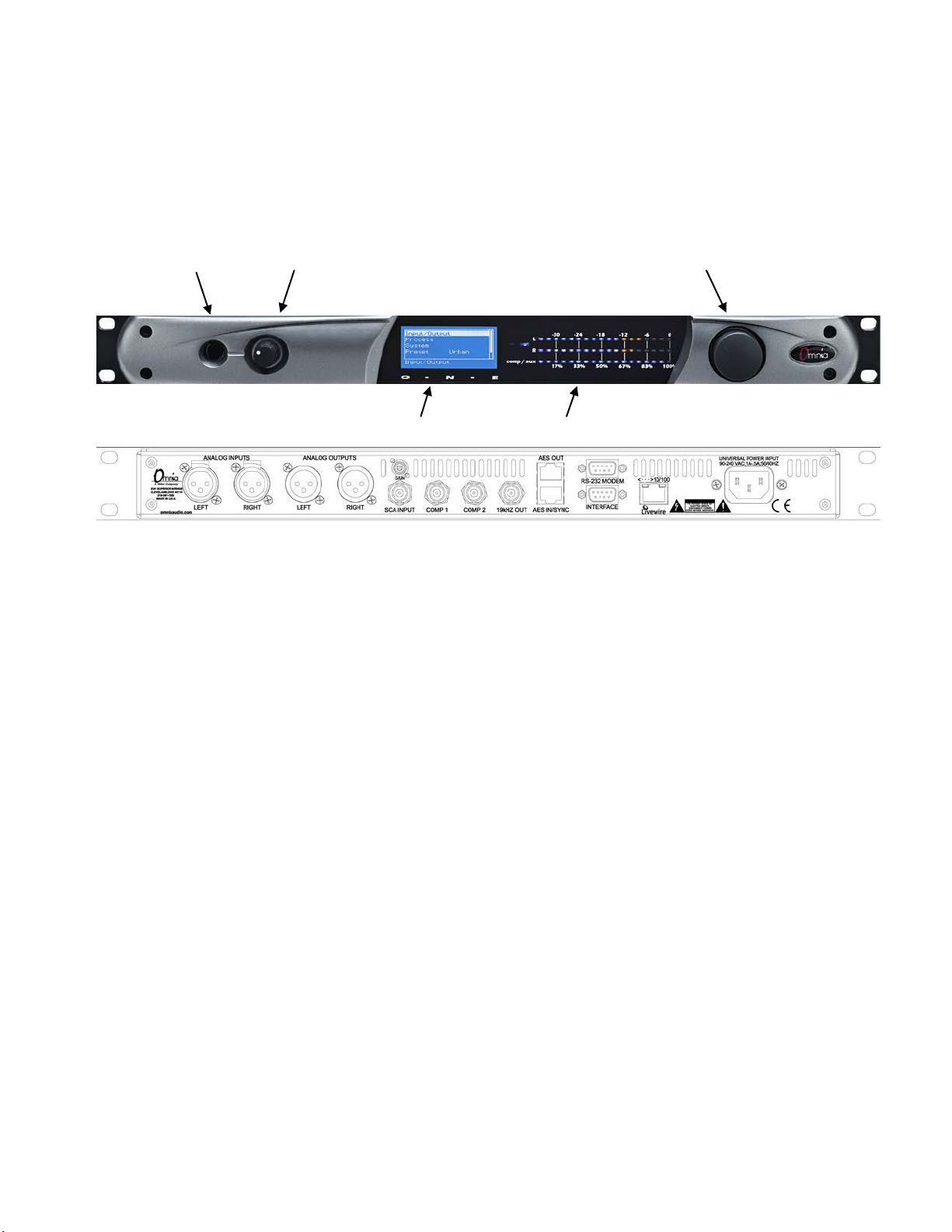
The following illustrations sh ow the location of the various controls and connectors associated with the installation:
Headphone Jack Headphone Level Control Jog Wheel
Main Menu / G/R Metering LCD Display Level Meters
1. Install the Omnia.ONE in the equipment rack using at least two rack screws. If only two screws are used, they MUST
be installed in the bottom holes of the rack ears!
2. Connect the audio inputs that are appropriate for your installation. The Omnia.ONE accepts balanced line-level analog
audio via the XLR connectors, AES/EBU digital via the bottom RJ-45 jack (using the “StudioHub” standard pinout) or
Livewire.
NOTE: Livewire audio I/ O is only to be used if you have an existing Axia or other Livewire syste m. O therwise, the
Livewire Ethernet jack can be used to remote control the Omnia.ONE via its built-in webpage interface. See Appendix
C in the full User Manual for details.
3. Connect the audio outputs in a manner that is appropriate for your installation. We suggest usi ng the composite MPX
BNC output s (and there fore the O mni a’s built-in MPX stereo generator) if at all possible for best performance.
4. Connect AC power to the unit (there is no po wer switch!)
5. Navigate to the Input/Output / M e te r Select setting and select Input.
6. Navigate to the Input/Output / I np ut / Inp ut Src setting and select the Analog, AES/EBU or Livewire input as
appropriate for your installation. If your audio source is active, you should now see meter activity on the LED
bargraph meters.
7. While driving the inputs with typic al program material at normal operating level , navigate back up to t he Input/Output
/ Input menu (by highlighting and clicking on the “<-EXIT” option) and adjust the appropriate input Level control
until the peak-reading input bargraph meters are peaking up to at least –15 and up to –12 dBFS or a little higher.
8. Navigate to the Input/Output / Out put / FM Opt i ons submen u and ensure that the Pre-Emphasis, De-emphasis and
BS-412 settings are correct for your system and your location. If you will not be us ing the O mni a’s built-in stereo
generator, it is very important to ensure that the Omnia i s the only device providing the FM pre-emphasis (PreEmphasis ON and De-Emphasis OFF) and that any link be tween the Omnia’s output and the input to the FM exciter
is fully linear with no codecs. If this is not possible, the Omnia must be lo c a te d at the transmitter site, driving the FM
exciter directly.
Page 6

iv
9. If yo u are using the Omnia’s built-i n s t ereo generator, navigate to the Input/Output / Stereo Generator menu and adjust
the appropriate composite output level control (Comp #1 or Comp #2) for 100% modulation on your station’s
modulation monitor. Similarl y, a djust the Pilot Lvl control so that the 19kHz stereo pilot injection level indicates
between 8 and 10 percent as shown on your station’s stereo modulation monitor. If your modulation monitor does not
show pilot injection but you are c e r ta in that the total modulation is correct at 100%, simply set the Pilot Lvl control to
9.0%.
If you are using the AES/EBU output to feed pre-emphasized audio to your linear STL or digital exciter, navigate
instead to the Input/Out put / Output menu and adjust the appropriate output level control for the equipment that
follows the Omnia.ONE. Ensure that any limiters, clippers and/o r pre-emphasis in the exciter/transmitter are defeated.
10. Navigate back to the Main Menu, highlight Preset: and clic k. Rotate the jog wheel to display the preset you would
like to start with and click to select it. G o through all of the presets and start wit h one that sounds best to you.
11. We suggest that each time you try a new factory preset, you adjust the Clip Drive in the Proce s s ing / Adjust
Processing / Clipper menu as follows: Starting with the default setting for a preset, adjust it down in 0.5 dB steps until
the loudness just drops below the d esired level and then bring it up slightly from there. This should be the optimum
setting for your statio n and market. With most presets, there should be roo m to turn it up a bit as well if a bit more
loudness is needed. Turn it up just enough to achieve the desired lo udness level. If you have t o turn it up too much, to
the point where distortion becomes obtrusive, it would probably be best to start with a more aggressive preset.
The Omnia.ONE Quick-Start Setup is now complete. For more detailed installation and oper a ting instructions (including
details about every control functio n) a nd to learn about some of the features that make the Omnia.ONE unique, please refer
to the latest version of the full Omnia.ONE user manual available on the Omnia website here:
http://omniaaudio.com/manuals
Page 7

v
Omnia.ONE.SG Quick-Start Setup
We know that you’re probably in a h urry to begi n using your new Omnia.ONE.SG. If you have technical expertise and
previous knowledge o f stereo generator fundamentals, using thi s guide will get you up and running a s quickly as possible.
Please refer to the full User Manual for a dditional installation and setup information.
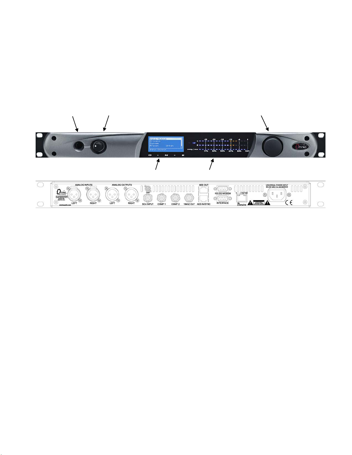
The following illustrations sh ow the location of the various controls and connectors associated with the installation:
Headphone Jack Headphone Level Control Jog Wheel
Main Menu / G/R Metering LCD Display Level Meters
1. Installation: Install the Omnia.ONE.SG in the equipment rack using at least two rack screws. If only two screws are
used, they MUST be installed in the bottom holes of the rack ears!
2. Connect the audio inputs that are appropriate for your installation. These should originate from an external FM
audio processor and ideally should be pre-emphasized and fully band limited to 16kHz.
3. Connect the Omnia’s composite MPX BNC output(s) as appropriate for your installation to your FM exciter’s
baseband composite MPX input or composite STL transmitter.
4. Connect AC power to the unit (there is no power switch!)
5. Navigate to the Discrete I/O / Meter Select setting and select Input.
6. Navigate to the Discrete I/O / Input / Input Src setting and select the Analog, AES/EBU or Livewire input as
appropriate for your installation. If your audio source is active, you should now see meter activity on the LED
bargraph meters.
Input Calibration: The Omnia ONE.SG is designed to accept pre-processed audio from an external FM audio processor.
Ideally, this audio should be pre-emphasized and sourced only through a lossless link using Livewire or AES/EBU.
Analog L/R XLR input can also be accepted. Since the Omnia ONE.SG includes a composite clipper, it is very
important to calibrate the input level p roperly so that when the Composite Clip Drive control is set to 0.0, no
composite clipping is taking pla ce.
7. Using typical pro gram material, turn up the main clipper drive on your external FM processor temporarily to provide
a more steady “worst-case” level at the input of the Omnia ONE.S G. If using a digital out put on the external FM
processor, s et its peak output level to -12.0dBFS if possible. If so, set the Omnia’s input Level control in the
Discrete I/O / Input menu to 0.0dB to start.
NOTE: The Omnia ONE SG’s input meters are specially calibrated with higher resolution above -12dBFS for easy and
precise input level calibration. T he first yellow LED comes on at -12.1dBFS, the second at -11.9dBFS and
subsequent ones every 0.2dB above that. The composite clip point (with 0.0dB drive setting) is -12.0dBFS.
Page 8

vi
8. In the Discrete I/O / Input submenu, adjust the appropriate input Level control until the peak-reading input bargrap h
meters are just lighti ng only the first one or two yellow LEDs. If there i s some overshoot in the output of your
external FM processor or the link between it and the Omnia ONE.SG, more than the first LED may light. This
should be OK as long as there is not more than a dB or so of overshoot. If there is more overshoot than that, you
may need to lower the input level a bit. Be sure in any case that the red “0”dBFS LED’s never light.
9. Ideally, the de-emphasis in the output of your external FM processor should be defeated so that the Omnia ONE.SG
is receiving a pre-emphasized, 16kHz band-limited signal. If not, you can turn pre-emphasis and low-pass filte ring
on. Navigate to the Stereo Generator / Adjust SG submenu and ensur e that the Emph Std (50us or 75us), Pre-
Emph (OFF or ON) and Input LPF (OFF or ON) settings are correct for your system and your location.
10. Here in the Stereo Generator / Adjust SG submenu, navigate down to the Comp #1 or Comp #2 controls and adjust
the appropriate one for 100% modulation on your station’s modulation monitor. Similarly, adjust the Pilot Lvl
control so that the 19kHz stereo pilot injection level indicates between 8 and 10 percent as shown on your station’s
stereo modulation monitor. If your modulation monitor does not show pilot injection but you are cer ta in that the
total modulation is correct at 100%, simply set the Pilot Lvl control to 9.0%.
11. To save your settings as an SG Config preset, navigate to the Save SG Config setting in the Stereo Generator menu,
click on “Name”, enter a preset name using the jog wheel, turn the jog wheel one more click clockwise and click on
“Save”. Similarly, I/O configuration presets can also be saved from the Discrete I/O menu.
12. Remember to return your external FM processor’s main clipp e r drive control to its previous level.
NOTE: To engage the special single-sideband mode available in the Omnia ONE .SG, navigate to the Stereo Generator /
Adjust SG submenu and set the SB Mode control to “SSB”. No other adjustments should be needed.
The Omnia.ONE Quick-Start Setup is now complete. For more detailed installation and oper a ting instructions (including
details about every control function) and to learn about some of the features that make the Omnia.ONE unique, please refer
to the latest version of the full Omnia.ONE user manual available on the Omnia website here:
http://omniaaudio.com/manuals
Page 9
vii
Omnia.ONE AM Quick-Start Setup
We know that you’re probably in a h urry to begi n using your new Omnia.ONE. If you have techn ical expertise and
previous knowledge of audio processor fundamentals, using this Quick-Start guide will get you up and running as quickly
as possible. P le a se refer to the full User Manual for additional installation and setup information.
The following illustrations sh ow the location of the various controls and connectors associated with the installation:
Headphone Jack Headphone Level Control Jog Wheel
Main Menu / G/R Metering LCD Display Level Meters
1. Install the Omnia.ONE in the equipment rack using at least two rack screws. If only two screws are used, they MUST
be installed in the bottom holes o f the rack ears!
2. Connect the audio inputs that are appropriate for your installation. The Omnia.ONE accepts balanced line-level analog
audio via the XLR connectors, AES/EBU digital via the bottom RJ-45 jack (using the “St udioHub” standard pinout) or
Livewire.
NOTE: Livewire audio I/O is only to be used if you have an existing Axia or other Livewire syst em. Otherwise, the
Livewire Ethernet jack can be used to remote control the Omnia.ONE via its built-in webpage interface. See Appendix
C in the full User Manual for details.
3. Connect the audio outputs in a manner that is appropriate for your installatio n. N ormally this will be mono balance d
analog output to your AM transmitter using either the LEFT or RIGH T output XLR. If you ha ve 2 transmitters, you
can use one output for each transmitter and thus have separate level adjustments for each.
4. Connect AC power to the unit (there is no power switch!)
5. Navigate to the Input/Output / M e te r Select setting and select Input.
6. Navigate to the Input/Output / Input / Input Src setting and select the Analog, AES/EBU or Livewire input as
appropriate for your installation. If your audio source is active, you should now see meter activity on the LED
bargraph meters.
7. If you will be running in mono, navigate to the Input/Output / Input / Mono Mode and select the desired mode. Mono
L will feed the left channel inp ut’s a udio to both output channels, M ono R the s ame for the right channel input. Mono
L+R will sum the left & right inputs and feed the sum to both outputs.
8. While driving the input with typical program material at normal operating level, navigate to the Input/Output / Input
menu and adjust the appropriate input Level control until the p e a k-reading input bargraph meters are peaking up to at
least –15 and up to –12 dBFS or a little higher.
Page 10

viii
9. Navigate to the Input/Output / Output / AM Options submenu and ensur e that the Output Polarities, LPF
Frequency, Asy m Mod and Tilt (normally only used for older plate-modulated transmitters) adjustments are correct
for your system and your locatio n. If you will be using asymmetrical modulation to increase your positive mo dulation
above 100%, ensure that when the Asym Mod control is t urned up, only the positive modulation peaks are increasing,
not the negative peaks. If you find the opposite is true, select Invert for the appropriate output in the menu above.
NOTE: To help make setting modulation levels and positi ve peaks easier, temporarily set t he Processing / Adjust
Processing / Clipper / Clip Drive control to a high s etting (such as 3.0dB).
10. Navigate to the Input/Output / Outp ut menu and adjust the approp r ia te c ontrol so that the output level is correct for the
equipment that follows the Omnia.ON E . Typically this will be the modulation level of your AM transmitter. Ensure
that the negative peaks never hit full-cutoff (100%) and then, if desired, increase the asym mod control until positive
peak modulation is between 120-125%.
11. Remember to return the Clip Drive control to its previous l e vel.
12. Navigate back to the Main Menu, highlight Preset: and click. Rotate the jog wheel to display the preset you would
like to start with and click to select it. G o through all of the presets and start wit h one that sounds best to you.
The Omnia.ONE Quick-Start Se tup is now complete. For more detailed installation and operating instructions (including
details about every control function) and to learn about some of the features that make the Omnia.ONE unique, please refer
to the latest version of the full Omnia.ONE user manual available on the Omnia website here:
http://omniaaudio.com/manuals
Page 11
ix
Omnia.ONE Multicast / DAB / Studio Pro Quick-Start Setup
We know that you’re probably in a h urry to begi n using your new Omnia.ONE. If you have techn ical expertise and
previous knowledge of audio processor fundamentals, using this Quick-Start guide will get you up and running as quickly
as possible. P le a se refer to the full User Manual for additional installation and setup information.
The following illustrations show the location of the various controls and connectors associated with the installation:
Headphone Jack Headphone Level Control Jog Wheel
Main Menu / G/R Metering LCD Display Level Meters
1. Install the Omnia.ONE in the equipment rack using at least two rack screws. If only two screws are used, they MUST
be installed in the bottom holes o f the rack ears!
2. Connect the audio inputs that are appropriate for your installation. The Omnia.ONE accepts balanced line-level
analog audio via the XLR connector s, AES/EBU digital via the bottom RJ-45 jack (using the “StudioHub” standard
pinout) or Livewire.
NOTE: Livewire audio I/O is only to be used if you have an existing Axia or other Livewire system. Otherwise, the
Livewire Ethernet jack can be used to remote control the Omnia.ONE via its built-in webpage interface. See
Appendix C in the full Use r Manual fo r details.
3. Connect the audio outputs in a manner that is appropriate for your installation. Choices are balanced line-level analog
audio via the XLR connectors, AES/EBU digital via the top RJ-45 jack (using the “StudioHub” standard pinout) or
Livewire. All outputs are activ e simultaneously.
4. Connect AC power to the unit (there is no power switch!)
5. Navigate to the Input/Output / M e te r Select setting and select Input.
6. Navigate to the Input/Output / I np ut / Inp ut Src setting and select the Analog, AES/EBU or Livewire input as
appropriate for your installation. If your audio source is active, you should now see meter activity on the LED
bargraph meters.
7. While driving the inputs with typic al program material at normal operating level , navigate back up to t he
Input/Outp ut / Input menu (by highlighting and clicking on the “<-EXIT” option) and adjust the appropriate input
Level control until the peak-reading input bargraph meters are peaking up to at least –15 and up to –12 dBFS or a
little higher.
8. Navigate to the Input/Output / Out put menu and adjust the appropriate control so that the output level is correct for
the equipment that follows the Omnia.ONE.
Page 12

x
9. Navigate back to the Main Menu, highlight Preset: and clic k. Rotate the jog wheel to display the preset you would
like to start with and click to select it. I t is best to go through all of the appropriate presets and start with one that
sounds best to you.
The Omnia.ONE Quick-Start Setup is now complete. For mo r e detailed installation and operating instructions (including
details about every control functio n) a nd to learn about some of the features that make the Omnia.ONE unique, please refer
to the latest version of the full Omnia.ONE user manual available on the Omnia website here:
http://omniaaudio.com/manuals
Page 13

xi
Table Of Contents
Welcome to Omnia.ONE! ........................................................................................................... i
What’s New? .................................................................................................................... i
President’s Message: ........................................................................................................ i
Omnia.ONE FM Quick-Start Setup ........................................................................................... iii
Omnia.ONE.SG Quick-Start Setup..............................................................................................v
Omnia.ONE AM Quick-Start Setup ......................................................................................... vii
Omnia.ONE Multicast / DAB / Studio Pro Quick-Start Setup ................................................ ix
S A F E T Y I N S T R U C T I O N S ....................................................................................xv
HAZARD / WARNING LABELS ............................................................................................ xvi
Manual Update Notification..................................................................................................... xvii
Chapter-1: Installation ..................................................................................................................1
Pre-Installation Tasks ............................................................................................................1
About This Manual ................................................................................................................1
Omnia.ONE Components......................................................................................................1
AC Power Environment ........................................................................................................1
Installation & Connections ...................................................................................................2
Rack Mounting & Grounding ............................................................................................. 2
AC Mains Power ................................................................................................................. 2
Rear Panel Connections ........................................................................................................3
Analog Audio Inputs and Outputs ...................................................................................... 3
A Note about Relative Phase: ............................................................................................. 3
Stereo Generator Connections (FM Style Only) ................................................................. 3
Composite Outputs 1 & 2 (BNC) (Active on FM and SG Styles Only) ..........................3
19 kHz Sync Output (BNC) (Active on FM and SG Styles Only) ..................................4
SCA Input (BNC) (Active on FM and SG Styles Only) ..................................................4
Ethernet / Livewire Connection .......................................................................................... 5
RS-232 Modem Connection (DB-9M)* ............................................................................. 5
General Purpose Interface (GPI) (DB-9F)* ........................................................................ 6
Powering Up ...........................................................................................................................6
Chapter-2: Getting To Know Your Omnia.ONE........................................................................7
The Omnia.ONE User Interface ...........................................................................................7
Headphone Level Control ................................................................................................... 7
Level Meters & Processing Bargraphs ............................................................................... 7
Audio I/O Level Display ..................................................................................................... 8
Processing Meter Display ................................................................................................... 8
Main Menu .......................................................................................................................... 9
Using the Jog Wheel ......................................................................................................... 10
User Interface Tutorial – Input Source Selection and Peak Level Setting ....................... 11
Proper Setting of Input Levels .......................................................................................11
An Important Word about Time Delay .............................................................................12
Chapter-3: Getting the Sound You Want ..................................................................................13
FM Style ................................................................................................................................13
Page 14

xii
The Factory Presets ........................................................................................................... 13
Increasing Density/Loudness ............................................................................................ 14
Adding More Detail — When Loudness Isn’t the Last Word .......................................... 15
Air-Sound Equalization Changes ...................................................................................... 15
Thunder Bass .................................................................................................................... 16
AM Style ...............................................................................................................................16
Using Omnia.ONE AM with Early PWM Transmitters ................................................... 16
The Factory Presets ........................................................................................................... 17
Increasing Density/Loudness ............................................................................................ 18
Adding More Detail — When Loudness Isn’t the Last Word .......................................... 19
Air-Sound Equalization Changes ...................................................................................... 19
Thunder Bass .................................................................................................................... 20
Multicast/DAB Style ............................................................................................................20
Purpose .............................................................................................................................. 20
Sensus Technology: Audio Processingx3 .................................................................... 21
Overview .......................................................................................................................21
Codec Provisioning ......................................................................................................21
Omnia.ONE Multicast and HD Radio ....................................................................21
So… what’s so smart about Sensus? .......................................................................22
Loudness Processing and Codecs ..................................................................................... 22
A Word About Density, Clarity, and Intelligibility .......................................................... 23
Quality Versus Density ..................................................................................................... 23
Increasing Density/Loudness ............................................................................................ 24
Adding More Detail—When Loudness Isn’t the Last Word ............................................ 24
Equalization (EQ) Changes............................................................................................... 25
Thunder Bass .................................................................................................................... 25
Coded Audio Considerations ............................................................................................ 26
Studio Pro Style ....................................................................................................................26
Purpose .............................................................................................................................. 26
Delay Throughput ............................................................................................................. 26
Equalization (EQ) Changes............................................................................................... 27
Presets ............................................................................................................................... 27
Bass Enhancement ............................................................................................................ 28
Chapter-4: Main Menu Selections ..............................................................................................29
FM Style ................................................................................................................................29
Preset ................................................................................................................................. 30
Processing ......................................................................................................................... 30
Save Preset ........................................................................................................................ 31
Delete Preset ..................................................................................................................... 31
Rename Preset ................................................................................................................... 32
<-Exit ................................................................................................................................ 32
Adjust Processing.............................................................................................................. 32
Input/Output ...................................................................................................................... 40
Administrative................................................................................................................... 47
Lock Front Panel ............................................................................................................... 49
Page 15

xiii
SG Style .................................................................................................................................50
Stereo Generator ............................................................................................................... 50
Discrete I/O ....................................................................................................................... 52
Administrative................................................................................................................... 57
Lock Front Panel ............................................................................................................... 58
AM Style ...............................................................................................................................59
Preset ................................................................................................................................. 60
Processing ......................................................................................................................... 60
Save Preset ........................................................................................................................ 60
Delete Preset ..................................................................................................................... 61
Rename Preset ................................................................................................................... 61
<-Exit ................................................................................................................................ 62
Adjust Processing.............................................................................................................. 62
Input/Output ...................................................................................................................... 70
Administrative................................................................................................................... 78
Lock Front Panel ............................................................................................................... 80
Multicast/DAB Style ............................................................................................................81
Preset ................................................................................................................................. 82
Processing ......................................................................................................................... 82
Save Preset ........................................................................................................................ 82
Delete Preset ..................................................................................................................... 83
Rename Preset ................................................................................................................... 83
<-Exit ................................................................................................................................ 83
Adjust Processing.............................................................................................................. 84
Input/Output ...................................................................................................................... 92
Administrative................................................................................................................... 97
Lock Front Panel ............................................................................................................... 99
Studio Pro Style ..................................................................................................................100
Preset ............................................................................................................................... 100
Processing ....................................................................................................................... 100
Adjust Processing............................................................................................................ 101
Input/Output .................................................................................................................... 108
Administrative................................................................................................................. 113
Lock Front Panel ............................................................................................................. 115
Appendix A: Performance Specifications ................................................................................117
Omnia.ONE FM .................................................................................................................... 117
Omnia.ONE SG ..................................................................................................................... 120
Omnia.ONE AM ................................................................................................................... 123
Omnia.ONE Multicast/DAB & Studio Pro......................................................................... 126
Appendix B: Troubleshooting/Service/Warranty ...................................................................129
Diagnostics and Error Messages.......................................................................................130
Electrical and mechanical safety note! .............................................................................131
Narrowing down problems................................................................................................131
Obtaining Service ...............................................................................................................132
Via the World Wide Web ............................................................................................... 132
Via E-Mail ...................................................................................................................... 132
Via Phone ........................................................................................................................ 132
Page 16

xiv
Warranty ............................................................................................................................133
Appendix C: Remote Control and Software Update Procedure ..........................................135
Remote Control ..................................................................................................................135
Remote ............................................................................................................................ 136
Preset Tab.....................................................................................................................137
Processing Tab .............................................................................................................137
In Tab ...........................................................................................................................138
Out Tab ........................................................................................................................139
IO Tab ..........................................................................................................................139
Encode Tab (FM Style Only) .......................................................................................139
Livewire .......................................................................................................................... 140
File Transfer .................................................................................................................... 141
Preset File Transfer ......................................................................................................141
I/O Configuration File Transfer ...................................................................................142
Trigger Scripts ................................................................................................................ 142
Software Update Procedure ..............................................................................................143
Special Notes: ................................................................................................................. 143
Appendix D: GPI using the “INTERFACE” connector (New in Version 2.6) ....................147
Page 17

xv
S A F E T Y I N S T R U C T I O N S
1. Read All Instructions. All safety and operating
provided for ventilation. They ensure reliable
operations of the product, keeping it from
overheating. These openings must not be blocked
provided through following the manufacturer's
Do not use any attachments not
the type of power source indicated on the marking
with a polarized AC plug with integral safety
routed so that they are not likely to be walked on
during a lightning storm, or when it is left
Do not overload AC wall outlets,
extension cords, or integral convenience outlets as
14. Object and Liquid Entry. Never push objects of any
cart, stand, tripod, bracket, or table. The product
may fall, causing serious damage to a child or adult,
the product needs to follow manufacturer's
care. Quick stops, excessive force, and uneven
surfaces may cause the product and the cart
Refer all servicing of the product to
the AC wall outlet and refer servicing to qualified
If the product does not operate normally (following
When the product exhibits a distinct change in
When replacement parts are
required, be sure the service technician has used
replacement parts specified by the manufacturer or
that have the same characteristics as the original
product, ask the service technician to perform safety
checks to determine that the product is in safe
d cleaners or aerosol
instructions must be read before operating the
product.
2. Retain All Instructions. All safety and operating
instructions must be retained for future reference.
3. Heed All Warnings. All warnings on the product
and those listed in the operating instructions must
be adhered to.
4. Follow All Instructions. All operating and product
usage instructions must be followed.
5. Heat. This produc t must be situated away fr om any
heat sources such as radiators, heat registers, stoves,
or other products (including power amplifi ers) that
produce heat.
6. Ventilation. Slots and openings in the product are
nor covered during operation. This pro duct should
not be placed into a rack unless proper ventilation is
installation procedures.
7. Water and Moisture. Do not use this product near
water – for example; near a bath tub, wash bowl,
kitchen sink or laundry tub; in a wet basement; or
near a swimming pool or the like.
8. Attachments.
recommended by the product manufacturer as they
may cause hazards.
9. Power Sourc es. This product must be operated from
label and i n the installation instructions. If yo u are
not sure of the type of power supplied to your
facility, consult your local power company.
10. Grounding and Polari zat i on. This product is equipped
ground pin. Do not defeat the safety ground in any
manner.
11. Power Cord Protection . Power supply cords must be
nor pinched by items placed upo n or against them.
Pay particular attention to the cords at AC wall
plugs and convenience receptacles, and at the point
where the cord connects to the product.
12. Lightning. For added protection for this product
unattended and unused for long periods of time,
unplug it from the AC wall outlet. This will prevent
damage to the product due to lightning and power
supply surges.
13. Overloading.
this can result in a fire or electric shock hazard.
kind into this product through openings as they may
touch dangerous voltage points or short out parts
that could result in a fire or electric shock. Never spill
liquid of any kind into the product.
15. Accessories. Do not place this product on an unstable
and serious damage to the product. Any mounting of
installation recommendations.
16. A Product a nd Cart Combination should be moved with
combination to overturn.
17. Servicing.
qualified service personnel.
18. Damage Requiring Servi ce. Unplug this product from
service personnel under the following conditions:
• When the AC plug is damaged.
• If liquid has been spilled or objects have fallen into
the equipment.
• If the product has been exposed to rain or moisture.
•
operating instructions).
• If the product has been dropped or damaged in any
way.
•
performance. This ind i cat e s a need for service.
19. Replacement Parts.
parts. Unauthorized substitutions may result in fire,
electric shock, or other hazards.
20. Safety Chec k. Upon completion of any repai rs to this
operating c on dition.
21. Cleaning. Do not use liqui
cleaners. Use only a dam p clot h fo r cleaning.
Page 18
xvi
HAZARD / WARNING LABELS
The Exclamation Point symbol, within an equilateral triangle, alerts the user to the
presence of important operating and maintenance (servicing) instructions in product
literature and instruction manuals.
The Lightning Flash With Arrowhead symbol, within an equilateral triangle, alerts
the user to the presence of non-insulated dangerous voltages within the product's
enclosure that may be of sufficient magnitude to constitute a risk of electric shock.
WARNING -- This equipment generates, uses, and can radiate radio frequency energy. If not
installed and used in accordance with the instructions in this manual it may cause interference to
radio communications. The device has been formally submitted for testing and found to comply
with the limits for a Class B computing device (pursuant to subpart J of Part 15 FCC Rules) and
has been designed to provide reasonable protection against such interference when operated in a
commercial environment. Operation of this equipment in a residential area may cause
interference, and the user and at his expense will be required to take any measures required to
correct interference.
CANADA WARNING – This digital apparatus does not exceed the Class B limits for radio
noise emissions set out in the Radio Interference Regulations of the Canadian Department of
Communications. Le present appareil numerique n'emet pas de bruits radioelectriques depassant
les limits applicables aux brouillage radioelectrique edicte par le ministere des Communications
de Canada.
CE CONFORMANCE – This device co mplies with the requirements of the EEC Co unci l Directives: 93/68/EEC
(CE Marking); 73/23/EEC (Safety – low voltage directive); 89/336/EEC (electromagnetic compatibilit y).
Conformity is declared to those standards: EN50081-1, EN50082-1.
Page 19

xvii
LITHIUM BA TTERY CAUTION – T here is a danger of explosion if the internal battery is
Manual Updates
http://www.omniaaudio.com/support/manuals.htm
Frequently Asked Questions (FAQ)
http://www.omniaaudio.com/support/faq.htm
Tech Tips & Support Bulletins
http://www.omniaaudio.com/tech/tips.htm
Software Upgrades & Remote S oftware
http://www.omniaaudio.com/support/updates.htm
White Papers & Technical Discussions
http://www.omniaaudio.com/tech/default.htm
replaced incorrectly or shorted. Replace the battery only with same or equivalent type
recommended by the manufacturer. Dispose of used batteries according to the manufacturer's
instructions.
USE OF SHIELDED CABLING – In order to conform to the CE requirements for High
Frequency radiation, shielded cables must be used for all audio and data connections.
NOTE: When the unit is operated in an extremely high RF environ ment, it may be helpful to
connect cable shields to the XLR-connector terminal that connects cable shield to chassis
ground, not to pin 1. Additionally, a 0.01uF capacitor connected between XLR pin-1 and the
chassis terminal may be helpful in some instances.
RoHS COMPLIANCE – The RoHS Directive stands for "the restriction of the use of certain hazardous substances
in electrical and electronic equipment". This Directive bans the placing on the European market of new electrical
and electronic equipment containing more than agreed levels of lead, cadmium, mercury, hexavalent chromium,
polybrominated biphenyl (PBB) and polybrominated diphenyl ether (PBDE) flame retardants. Omnia.ONE FM is in
compliance with the EU RoHS Directive.
Manual Update Notification
Audio Processing – a unique art form that we take very seriously!
As part of our dedication to the science of audio processing we will continue to improve and update the Omnia
product and its documentation based on our ongoing research, real-world field experience, and the valued input from
our many thousands of loyal custo mers.
We strongl y encourage our customer s to visit o ur Omnia website for product enhancement announcements, software
updates, updated user manuals, and customer support bulletins.
The following URLs ha ve been included for your convenience:
Page 20

1
Chapter-1: Installation
Pre-Installation Tasks
Please take a few minutes to read through this chapter before proceeding with the installation. This section offers
common procedures for installing your new Omnia.ONE processor.
About This Manual
This manual is now written to cover all 4 styles of the Omnia.ONE. This chapter will cover only general installation
topics. Topics unique to a specific style are covered in style-specific sections within Chapters 3 and 4. The latest
version of this manual is always available for download from the Omnia website here:
http://www.omniaaudio.com/support/manuals.htm
Omnia.ONE Components
By now, you’ve unpacked the shipping carton to gain access to this manual. Now is the time to inspect the
Omnia.ONE unit and its shipping carton for any signs of shipping damage. Such damage must be reported to your
carrier for any claims. The Omnia.ONE shipping box includes the following components:
Omnia.ONE processor.
Omnia.ONE Operating Manual.
Warranty Registration Card. (Please complete the form and return/FAX it to Telos/Omnia)
Two IEC Power Cords, one of the USA/Canada style, and one of t he Euro style.
One each Male and Female XLR to StudioHUB RJ45 adaptor cables.
AC Power Environment
The Omnia.ONE subsystem is a DSP-based microcomputer, and therefore requires reasonably clean AC power, just
as any modern computer system does. And even though t he Omnia.ONE power supply is equipped with robust AC
transient suppression, we recom mend that an “online” style (non-switc hing type) Uninterruptible P ower Supply
(UPS) with tr ansient surge suppr ession be e mpl oyed.
At transmitter sites there can be heavy transients on the power lines as well as significant surges introduced into the
power system by freque nt lightin g s t rikes. These are unwelcome power line events and can damage even the most
robust equipment. Therefore you should give the AC power environment and ins tallation practices thorough
consideration before plugging in the Omnia.ONE (or any other microcomputer-based equipment).
A White Paper by one of our Support Engineers can be found on the Telos Systems website at the URL listed below.
It details proper grounding and contains links to some surge suppression products for both the power mains and the
often-neglected telephone, Ethernet and ISDN line connections that can (and do) conduct powerful surges into the
equipment.
http://www.telos-systems.com/techtalk/surge.htm
Page 21
2
Installation & Connections
Rack Mounting & Grounding
The Omnia.ONE requires one RU (1.75" [44.45 mm]) of rack space. Rack mount the unit using four rack screws. If
only two screws are going to be used, they should be in the bottom holes in the Omnia front panel. No other twoscrew mounting arrangement will prevent di s tortion of the front pa nel!
Adequate ventilatio n should be provided, and it is always good engineering practice to allow one blank rack space
immediately above and below the Omnia, especially if equipment generating significant heat is located below the
unit. You may install 1RU (1.75") vented or solid rack panels to fill these spaces.
The processor should be installed into a properly grounded 19" equipment rack.
It is a good idea, especially at transmitter sites, to run a separate ground strap or braid from the Omnia.ONE’s
chassis to a solid rack or station ground point. Although no separate ground lug is provided, the end of the strap or
braid can be clamped under the Omnia’s top cover using the Omnia’s existing top cover screws.
AC Mains Power
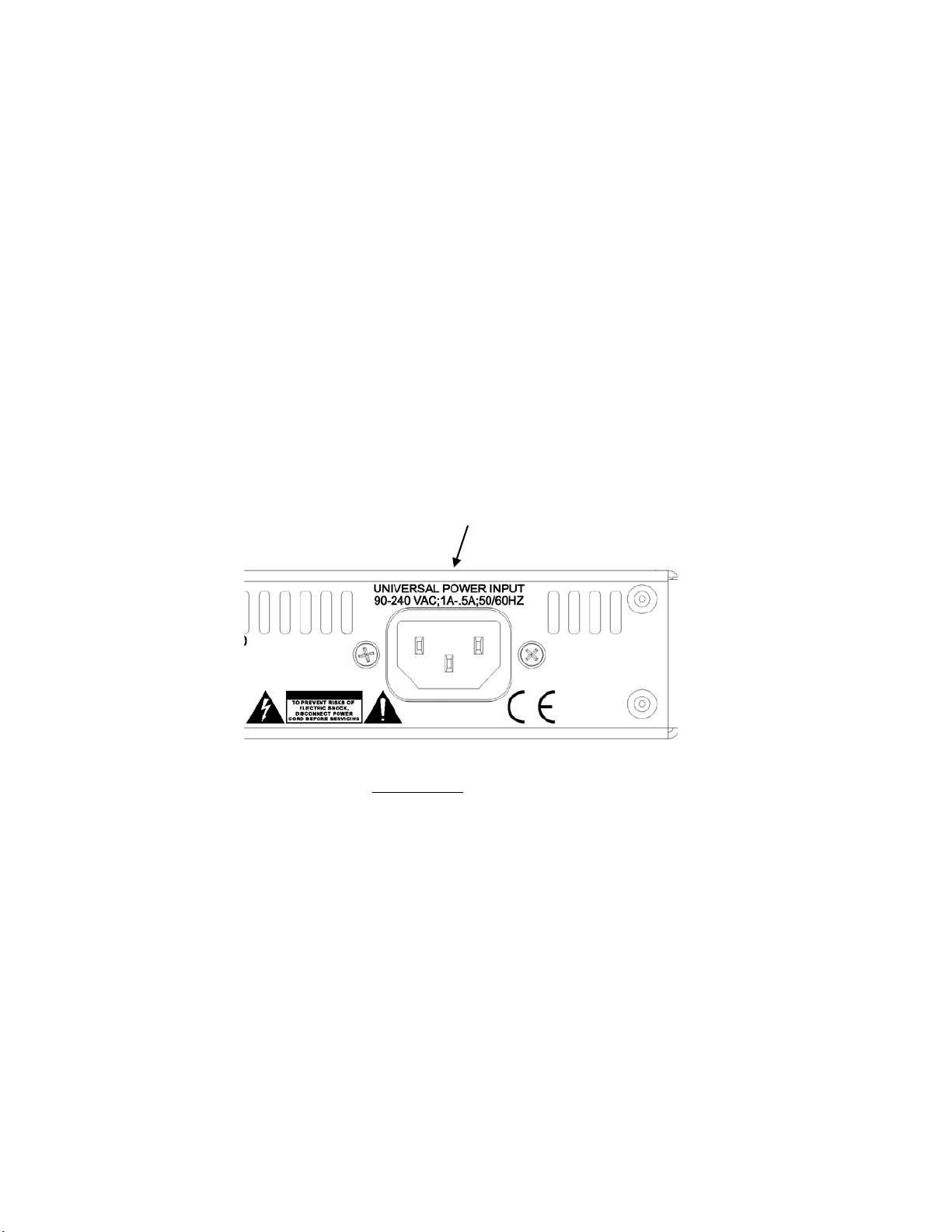
AC Power Connection
Omnia.ONE utilizes an un-switched EMI-filtered IEC power-entry module.
Omnia.ONE’s automatic voltage–sen si ng, hi gh -efficie ncy switching power suppl y allows it to operate on AC mains
voltages from 100 to 240 VAC and from source frequencies of either 50 or 60 Hz.
In the USA or Canada, plug the provided IEC type AC power cord into the unit and then into a grounded AC outlet.
Outside of the USA you must use the appropriate power cord that complies wi th loc a l e le ctrical regulations.
After power is first applied to the Omnia.ONE, the LCD scr een, the “in” and “out” LED’s and the rightmost
segments of the LED bargraph meters should light.
After about 20 seconds the LCD screen should show “Omnia.ONE” and at about 30 seconds the Main Menu should
appear. Once the Main Menu appears the unit is ready for use.
Page 22
3
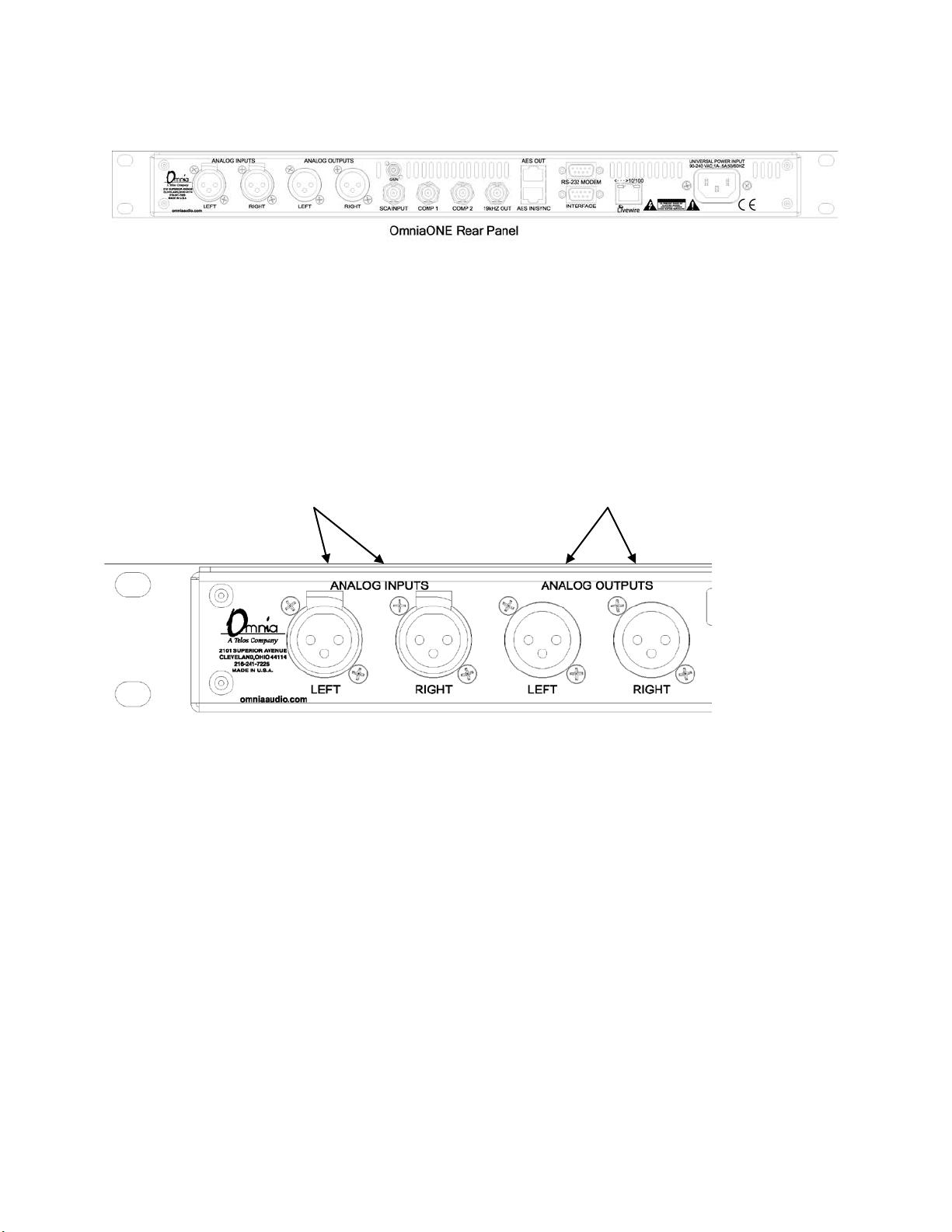
Rear Panel Connections
Analog Audio Inputs and Outputs
Balanced XLR-type connectors are used for the analog audio. Both analog and digital input sources may be
connected simultaneously, however, only the input source that has been selected is active. Analog/Digital/Livewire
Input source selection is done through the “Input Src” (Input Source) software parameter setting in the Input
submenu of the Input/Output menu.
All outputs are active simultaneously.
The stereo analog inputs Individual Left and Right
are designed for standard analog outputs are available
+4dBu balanced signals. on two male XLR jacks.
Pin 2 is Hot. Pin 2 is Hot.
A Note about Relative Phase:
If the relative phase of your installation (including the Omnia.ONE) differs from that of your exis t ing syste m, your
announcers may feel that they sound “weird” i n their headphones. If this occurs, then the relative phas e of the
processor is 180 degrees from what your air talent is used to. To remedy this, you can either reverse the polarity of
both of the analog inputs or simply change the “Invert” setting to [Both] in the Input submenu of the
Input/Output menu.
Stereo Generator Connections (FM Style Only)
Four standard female BNC connectors comprise the Omnia.ONE’s stereo generator connections.
There are two composite MPX outputs with independent software level controls, one SCA input with level adjust
trimpot and one 19 kHz pilot sync output.
Composite Outputs 1 & 2 ( BNC) (Active on FM and SG Styles Only)
These two low impedance outputs (Composite 1 and Composite 2) are each capable of driving up to 100 feet of
RG-58A/U coax cable. The output levels are individually adjustable so the unit can operate as a “composite
DA” to drive a variety of equipment. The output leve ls and other stereo generator settings are set through
software parameters in the Stereo Generator submenu of the Input/Output menu. An internal jumper sets the
Page 23
4
output impedance to either 5 ohms (the factory setting) or 75 ohms. The default setting is appropriate for the
vast majority of excite r connections. However, in the event that a higher source impedance is required, a jumper
can be moved (one for each composite output) on the motherboard to change the source impedance to 75 ohms.
For reference, JP10 is for Composite #1, and JP9 is for Composite #2.
Jumpers JP7 & JP8 are also available if you need to limit the maximum peak-to-peak output voltage fro m t he
composite outputs to 4v p-p instead of the normal 10v p-p. They de fault to the Normal (10v p-p) setting.
19 kHz Sync Output (BNC ) (Active on FM and SG Styles Only)
This TTL-level 19 kHz square wave output can be used as the reference signal for most RDS or SCA generators
that operate at 57 kHz or other multiple of the 19 kHz pilot frequency. This Sync output is phase and fre quency
locked to the stereo pilot. When this signal is used to synchronize an external SCA or RDS generator, this
locking assures that no difference frequencies exist which may cause intermodulation components between the
pilot and the SCA signal.
SCA Input (BNC) (Active on FM and SG Styles Only)
Any SCA or RDS signal above 53 kHz can be added to the composite outputs of the Omnia.ONE by connecting
the signal to the SCA INPUT connector. The SCA signal is mixed in the analog domain directly into both
composite outputs. A high-pass filter on the SCA input provides SCA to main-channel crosstalk protection. The
SCA inject ion level can be adjusted using the rear panel Gain trimpot.
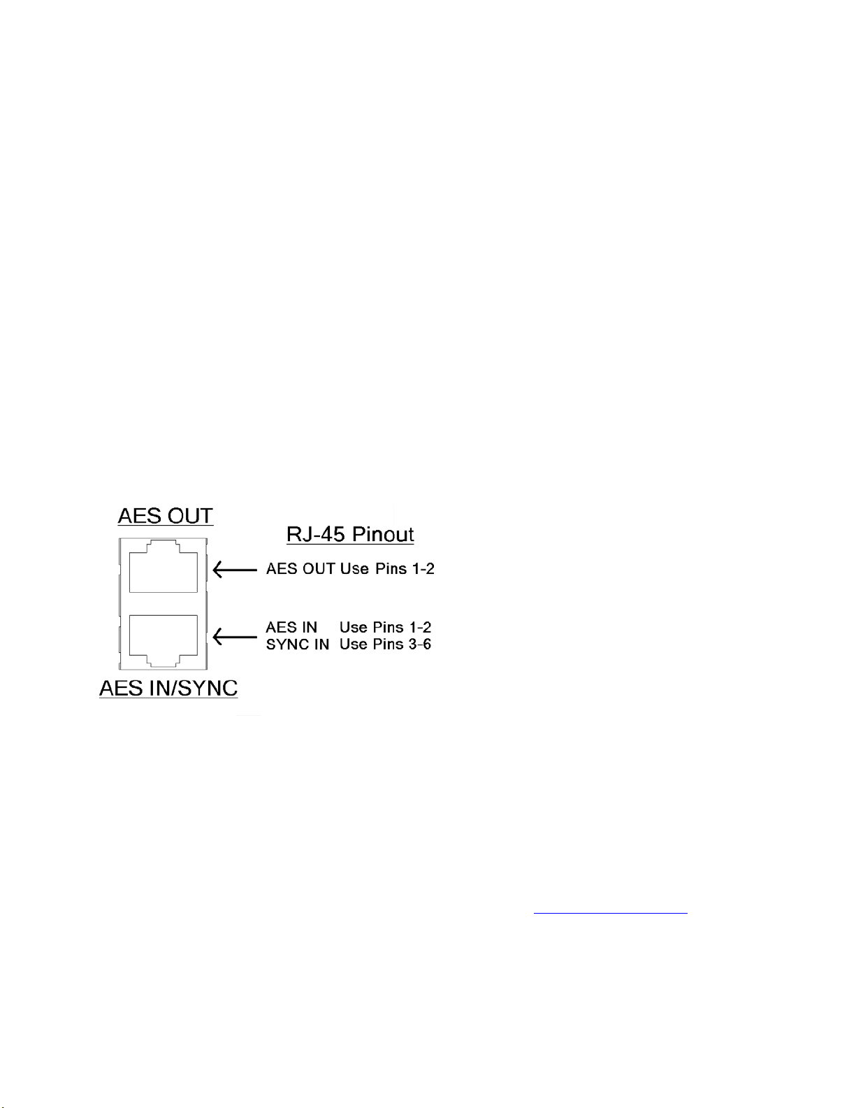
AES/EBU Digital Input, AES/E BU External Sync Input, and AES/EBU Output
(GREEN Male XLR)
(GREEN Female XLR)
(RED Female XLR)
The digital AES/EBU (AES-3 ) inputs (IN and EXT. SYN C ) use industry-familiar RJ-45 connectors and utilize the
StudioHUB+ wiring standard
1
. They accept any sampling rate between 32kHz and 96kHz. No user adjustment of the
sample rate is necessary on the AES-3 input as a high-quality digital sample rate converter is built in.
There is one AES-3 output on a standard RJ-45 connector that provides either an inter nally generated output sample
rate of 48 kHz or the sample rate can be locked to an external AES/EBU signal applied to pins 3 & 6 of the the AES
IN / SYNC IN connector or to the AES/EBU input signal. These options are selectable using the “Samp. Rate”
setting in the Output submenu of the Input/Output menu.
Note: The analog and digital outputs are active simultaneously.
1
More information about the StudioHU B+ wiring scheme can be found at: http://www.studiohub.com/
For your convenience, two XLR adaptor cables are supplied with the unit. The male XLR lead with the GREEN
shrink tubing is used fo r AES OUT. The male XLR le ad with the RED shrink tubing is not used.
The female XLR lead with the GREEN shrink tubing is used for AES IN and the female XLR l ead with the RED
shrink tubing is used fo r AES EXTERNAL SYNC IN.
Page 24
5
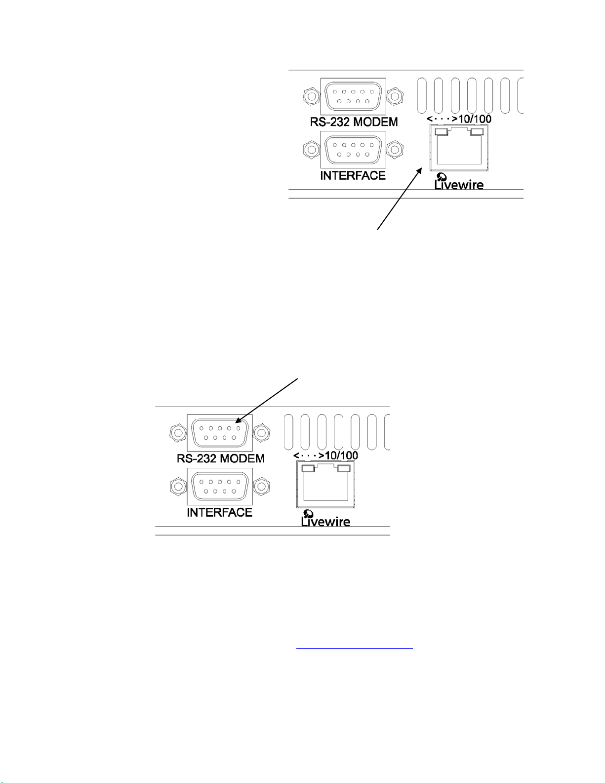
Ethernet / Livewire Connection
The RJ-45 10BaseT / 100BaseT Ethernet / Livewire
I/O jack can be used simultaneously for both
TCP/IP based remote control of your Omnia.ONE
and audio input/output to your existing Livewire
network.
Ethernet 10BaseT/100BaseT Remote and Livewire I/O
RS-232 Modem Connectio n (DB-9M)*
This DB9-male connector can be used to connect an external dialup modem for a bi-directional computer remote
control connection.
NOTE: This connector is for a remote control external modem connection only. Please see Appendix B for
information on how to use a ter minal pr ogram along with an internal RS-232 connector for troubleshooting
purposes.
1
RS-232 Modem Port
NOTE: Yo u must use a standard straight-through serial cable and not a null mode m cable when c onnecting the RS232 connector of the Omnia and the external modem. Typically this would be 9-pin to 25-pin cable. (External
modems trad i tionally have 25 pin c onnectors i n "DCE" configuration. The Omnia.ONE has a 9 pin in "DTE"
configuration, so the standard 9-pin to 25-pin cable will work).
1
The setup and operation of the Omnia Remote Control application is covered i n detail in Appendix C.
*Please note that the RS-232 Modem functionality is not yet i mple mented in the current software but will be
available with a free downloadable software update. Please check the Omnia website for new software
announcements, download links and manual updates at: http://www.omniaaudio.com/
Page 25
6
General Purpose Interface (GPI) (DB-9F)*
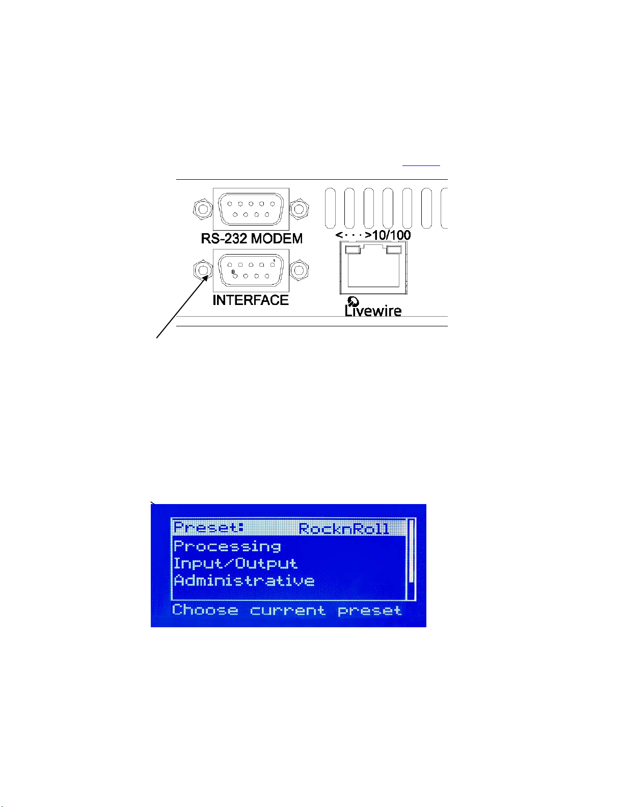
This DB9-female connector serves as a four-input, op toisolated interface to the Omnia's int e r nal GPI functions. Four
of the pins are “ground-sink” inputs, one is a bias voltage input, one is a +5V power output, and the remaining three
are “ground .” The inputs can be used to dynamically alter the Omnia.ONE’s operation in response to logic
transitions on the interface connection.
Full details, including connector pinout, are covered in Appendix D, starting on Page 147
DB-9M GPI “Interface” Connector
.
Powering Up
Now you are ready to power up the Omnia.ONE for the first ti me.
Connect AC power to the unit using the appropriate supplied power cable for your location.
(There is no power switch!)
When the Omnia.ONE is first powered on, audio will appear at the analog audio outp uts in approximately ten
seconds. The AES/EBU and Livewire outputs also become usable at this time however full initialization of the
digital ports is not complete for sever a l more seconds and a small audio glitch may be heard when the final sample
rate converter initialization is complete. Once the boot process is finished the following Main Menu will appear:
Page 26
7
Chapter-2: Getting To Know Your Omnia.ONE
The Omnia.ONE User Interface
Now that yo ur Omnia.ONE is rack-mounted, connected to a program audio source, and turned on, you’re ready to
learn how to operate it! This chapter covers the Front Panel User Interface, your window into the Omnia.ONE
processor.
A front panel jog-wheel with integral p ush switch, LED bargraph peak-reading level meters and a backlit LCD
display that is switchable between menu and AGC/Limiter metering screens make up the primary Omnia.ONE User
Interface. The front panel menu access may be password protected to prevent unauthorized tampering with
processing or p resets.
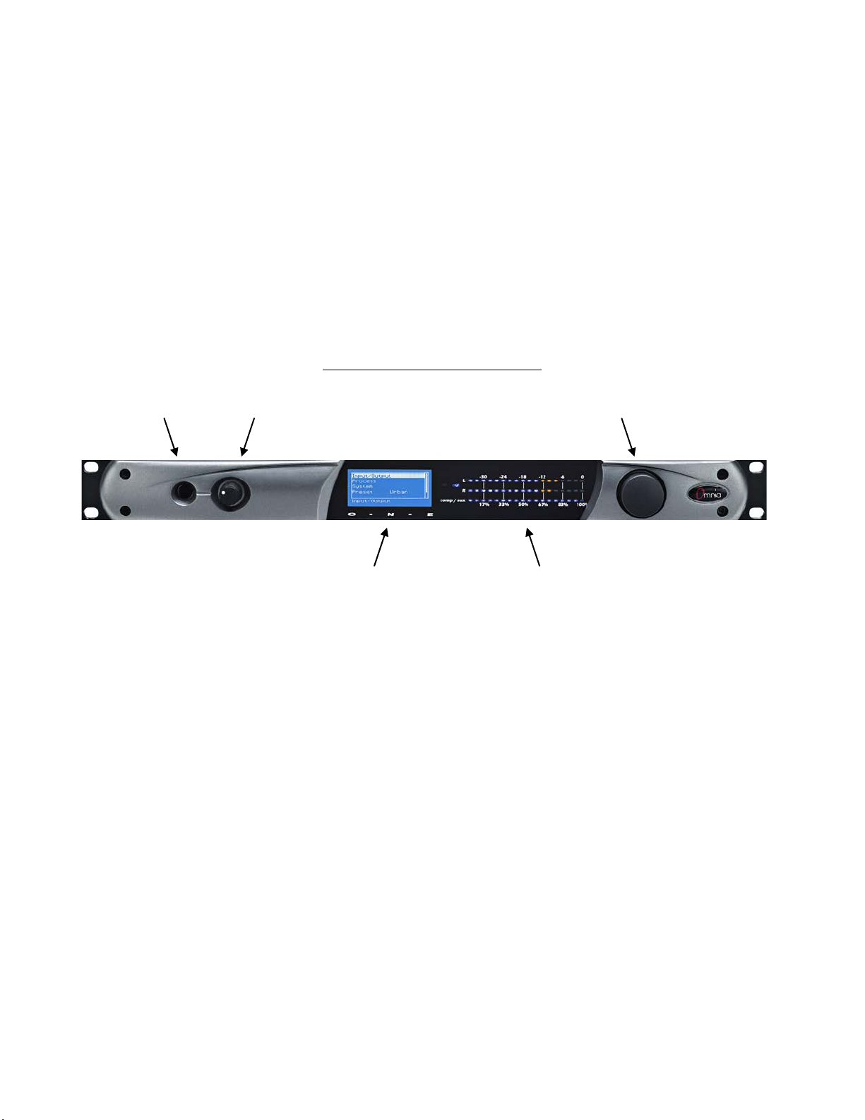
Omnia.ONE Key Front Pane l Fe atures
Headphone Jack Headphone Level Control Jog Wheel
Main Menu / G/R Metering LCD Display Level Meters
Headphone Level Control
A standard ¼" TRS stereo headphone jack is located at the left side of the front panel and allows the processed
signal to be monitored. The Headphone volume level control is physically located to the right of the headphone jack.
The headphone amplifier itself is a high-headroom design and is driven by its own high quality D/A converter that is
independent of the anal og XLR outputs. Therefore level changes in ei t her output will not affect the other.
Level Meter s & Processing Bargraphs
The top two of the three horizontal meters show digital sample-accurate peak representations of the left and right
channel input or output levels. Whether thes e bargraphs are displaying Input, Analog O utput, AES/EBU Output or
Livewire Output levels is selectable from within the Input/Output menu. A front panel i ndicator confirms which
level view has been selected, Input or Output.
The bottom horizontal meter (marked “comp / aux”) displays the composite MPX level from the stereo generator
before the output level controls. (Active on FM and SG Styles Only)
Page 27
8
Audio I/O Le vel Display
Either input or output levels can be displayed on the top 2 (L & R) meters. The highest LED illuminated indicate s
digital sample-accurate peak signal levels. The meters are calibrated in dec ibels below full scale digital (0 dBFS) in
2dB steps. 0 dBFS is the absolute maximum level in the digital domain. Levels from –34 dBFS to –14 dBFS are
displayed in blue, levels from –12 to –2 dBFS are displayed in yellow and 0 dBFS (the clipping point) is displayed
in red. The bottom meter displays the composite MPX signal level referenced to 100% modulation (FM and SG
Styles Only).
Audio I/O Level Display
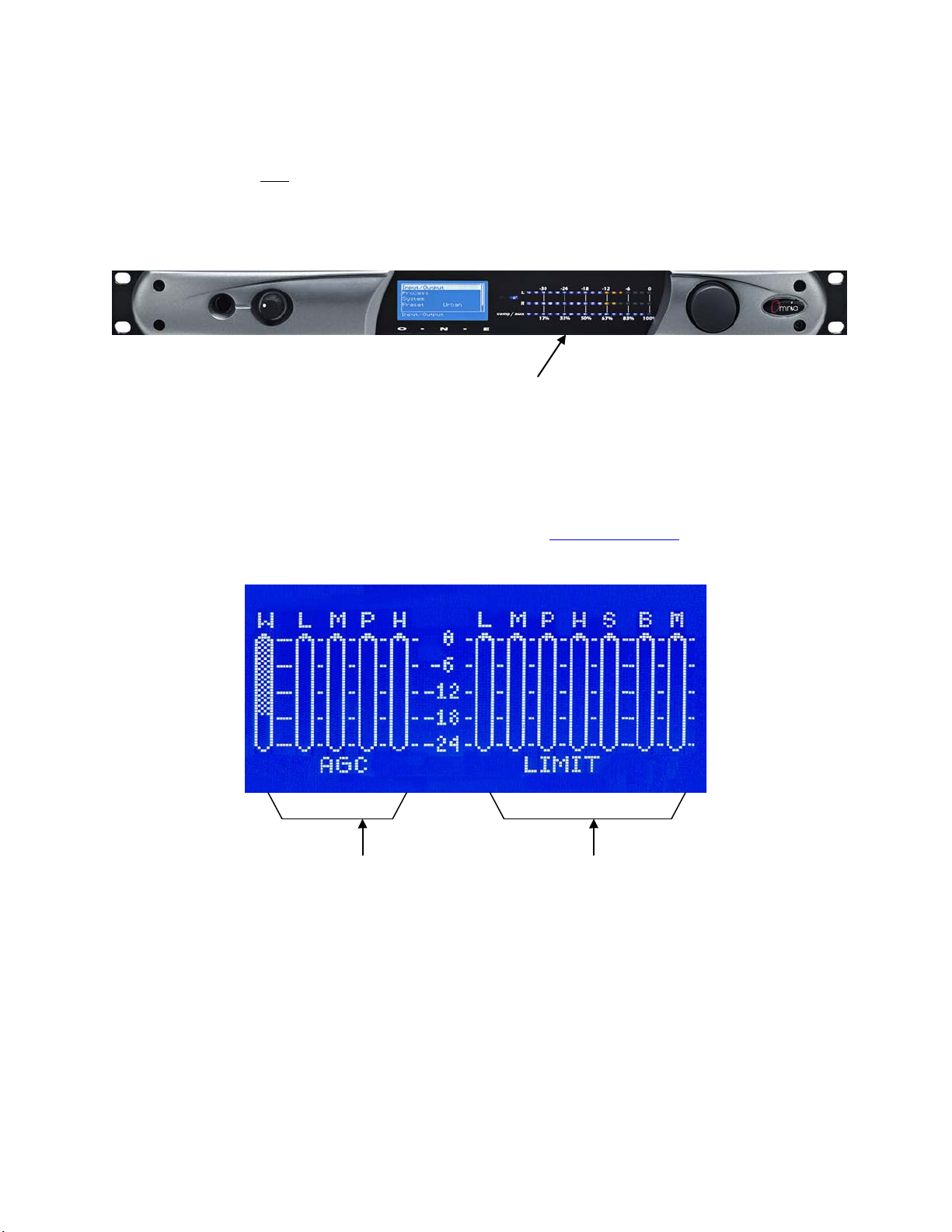
Processing Me te r Dis play
In “Meter Display” Mode the vertical bargraphs show all of the processing activity (the amount of gain reduction) in
the AGC, Limiter and Clipper sectio ns within the Omnia.ONE. (varies with style) If the “Menu Display” is
currently showing on t he Omnia.ONE’s LCD screen, press and hold t he jog-wheel for two seconds to switch to the
processing meter display as shown below.
To return to the Menu display, simply click the jog wheel once. (See “Using the Jog Wheel
” on Page 10)
FM Style Processing Meter Display
AGC Meters Limiter/Clipper M e te rs
W…... Wide Band AGC L….. Low Band Li miter
L……. Low B and AGC M…. Mid Band Limiter
M…… Mid Band AGC P…... Presence Band Limiter
P…… Presence Band AGC H….. High Band Limiter
S…... Super-High Band Limiter (optional on
FM style only)
H…… High Band AGC B….. Bass Clipper
M…. Main Clipper (AM & FM Styles)
or F…..Final Limiter (MC & SP Styles)
Page 28
9
Important Notes:
• A solid white bar will drop downward from the top to display the amount of gain reduction in each
processing band. The change from a solid bar to a checkerboard pattern indicates a “gated” condition
in that band .
• The wideband AGC and four-band AGCs will recover to a resting gain setting which coincides with
the RTZ (Return To Zero) levels set for each band.
• The Clipper meters are peak reading, showing the maximum amount of clipping that occurred over
the past 30 milliseconds. The Main clipper meter (FM & AM Styles Only) will indicate higher
amounts of clipping on bright program material because the Main Clipper is operating on the preemphasized audio signal. This is normal and does not indicate the perceived amount of audio
distortion.
Main Menu
The Omnia.ONE menu system has been designed to be intuitive and simple to use. Most operating parameters can
be found under one of the menu headings and sub-headings, allowing adjustments to be made quickly and with ease.
Rotating the jog-wheel s equentially highlig hts each menu item in turn. (See “Using the Jog Wheel
When the jog wheel is pressed inward (clicked) while a menu item is hig hlighted it will open that item’s submenu.
Similar behavior occurs when selections are made within the various submenus.
To return to the previous level, rotate the jog wheel until <-Exit is highlighte d and then press the jog wheel inward.
(Click) This will return you to the next highest level in the menu structure. NOTE: Some of the l onger men us have
an <-Exit option at the to p of the menu as well as at the bott om.
” on Page 10)
The Omnia.ONE Main Menu offers five selections
• Preset
• Processing
• Input/Output
• Administrative
• Lock Front Panel (not visible in the above screenshot)
:
Page 29
10
Using the Jog Wheel
The main user control for the Omnia.ONE is the easy to u se jog wheel with its integral push-switch. Using the
control is both intuiti ve and effici ent, making it easy to navigate the menu structure of the Omnia.ONE. Processing
changes and system adjustments can be quickly made with ease without having to remember multiple controls, their
positions, and what they do in each menu. T he behavior of the Omnia.ONE's menu system is consistent across pages
and is easy to learn. We believe that you will quickly become comfortable with how it works, and appreciate its
simplicity.
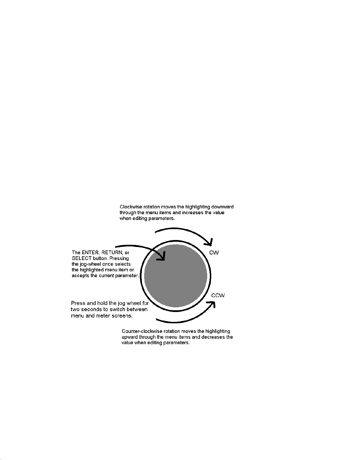
Clockwise rotation moves the highlighting in a menu downward and increases a value when editing parameters.
Counterclockwise rotation moves the highlighting in a menu upward and decreases a value when editing parameters.
Pressing inward on the jog-wheel activates the Enter, Return or Select button function as follows:
Pressing the jog-wheel inward once (also called “clicking”) selects the highlighted menu item or accepts the current
parameter value. Think of it as a vertical mouse button.
Pressing and holding t he jog-wheel in for two seconds will switch the L CD screen to a display of the processing
meters so that the gain-reduction activity of the AGC and Limiter sections can be monitored.
Clicking onc e when the metering screen is displayed will r eturn the d isplay to the menu scre en.
Page 30

11
User Interface Tutorial – Input Source Selection and Peak Level Se tting
wheel to display it.
The following two exercises are a useful introduction to the user interface. Start from the Main Menu (as displayed
when the unit is first turned on).
The first exercise changes a parameter selection (the Input Source selection):
Rotate the jog-wheel to highlight Input/Output.
Click the jog-wheel (push on the wheel once until a click is felt and release) to bring up the Input/Output
menu.
Rotate the jog-wheel to highlight Input and cli ck.
Rotate the jog-wheel to highlight Input Src and click.
The factory default selection for Input Source is Analog. To change the input selection to AES /E BU digital
or Livewire, rotate the jog-wheel un til [AES/EBU] or [Livewire] is displayed and click. If you are using
the analog inputs, rota te the jog wheel to display [Analog] and click to reselect the analog inputs.
To return to the top level of the Main Menu, rotate the jog-wheel to highlight <-EXIT and click. Repeat
until the top level (Main Menu) is reached. NOTE: Many of the Omnia.ONE’s menus have an <-EXIT
selection at both the top and bottom of the menu.
The next exercise adjusts a parameter that uses a value (the analog master input level setting):
The Main Menu display should still be showing on the LCD scre en. If not, click the jog-
Highlight Input/Output and click.
Highlight Mtr Select, click, rotate the jog wheel until [Input] is displayed and c lic k. This sets the first 2 LED
meters to monitor the Left and Right channel input levels.
Rotate the jog wheel clockwise to highlight Input a nd click.
Rotate the jog wheel to hig hlight Anlg Level and click the jog-wheel to select the control.
Rotate the jog-wheel CW to increase the input level. Rotate the jog-wheel CCW to decrease the input level.
This control adjusts b oth channels t ogether i n precise 0.5 dB steps. The gain in dB is shown to the right of t he
“control.” Watch the Left and Right channel LED meters while adj usting p e r the following section below.
Proper Setting of Input Le vels
With normal program audio levels applied, a correct input level setting will result in peak indications on the L & R
LED meters achieving –12 dBFS or a little higher (just into the yellow). This gain setting corresponds to system
headroom of about 12 dB. You may adjust the input level lower for more headroom if you wish. Setting the input
level for higher meter indications (less headroom) is strongly discouraged unless t here is another level-control
device prior to the Omnia.ONE that will keep the input levels from reaching the maximum digital level of 0 dBFS.
During normal operation, you should never see the red “0” segments light.
Once the desired level setting is reached, click the jog-wheel to accept that value. This returns the jog-wheel
to Select Mode.
You may highlight a nd click Right Trim to adjust its gain separately from the left channel if the input source
is not well balanced. In this mode the right channel gain can be adjuste d over a range of plus and minus 3 dB
Page 31

12
relative to the gain setting of the left channel.
To return to the top level of the Main Menu, rotate the jog-wheel to highlight <-Exit and click. Repeat until
the top level (Main Menu) is reached.
All of the Omnia.ONE’s software parameters are set in a similar fashion using the jog-wheel to scroll through menu
items. Clicking a highlighted item selects it; when that item is a control, the jog-wheel adjusts the value or level.
Clicking accepts the value or level and returns the jog-wheel to Select Mode.
Note: Altering any processing or gain parameter will instantly be reflected in a change in the Omnia.ONE’s output
characteristics because adjustments occur in real time. Therefore any adjustments you make will be instantly heard
as they occur.
An Important Word about Time D elay
A question commonly asked about Omnias is “How much time delay doe s it have?” The answer: “Not enough to
drive your DJ’s crazy!”
Certainly, there is reason for concern about the propagation delay through any digital transmission device, audio
processors included. We have measured the propagation time delay, the amount of time it takes for the audio signal
to travel from the analog input of Omnia.ONE to the output at approximately 7.7ms for the FM Style when using
AES/EBU digital I/O, about 9.2ms when using analog I/O. This is enough for a slight voi ce-character coloration to
be audible to the person speaking, but usually not enough to be a problem for talent monitoring off the air.
The delay through the AM style is ab out 7.0ms(digital I/O) 8.5ms(analog I/O ) and the delay through the Mult ic a st
style is about 7.6ms using digital I/O and 9.1ms using analog I/O.
For the Studio Pro style, please see the “Delay Throughput” section in the Studio Pro Style section of Chapter 3. The
Studio Pro style was designed to minimize the delay throughput by allowing the bypassing of the Bass EQ and Final
Limiter sections.
If there is additional delay added to the system, such as that adde d by certain types of Digital STL, the cumulative
delay may become excessive and cause discomfort for the on-air talent.
Real-world tests conducted by Jeff Goode in Indianapolis determined that a slight echo may begin to be heard at 1015ms, and that anything above 25-30 ms is usually too annoying to talent for monitoring off-air.
Page 32

13
Chapter-3: Getting the Sound You Want
This chapter is divided into four sections, one each for the 4 different Omnia.ONE processing styles, begi nning with
the FM style below.
Please refer to the section that applies to the style your Omnia.ONE is running:
AM style: Page 16
Multicast/DAB style: Page 20
Studio Pro style: Page 26
The SG style is not covered in this chapter since it contains no processing.
FM Style
Welcome to the OMNIA.ONE FM!
Don’t let the small single-rack sized package fool you! Omnia.ONE’s new hardware platform allows us to pack
more power in its single rack space than the original Omnia.FM had in three!
This chapter explains generally how to alter the sound of the Omnia.ONE FM factory presets, if desired, using the
controls explained in the Adjust Processing section of Chapter 4. Always go through all of the factory presets first,
regardless of their name, and start with the factory preset that is closest to the sound you are looking for.
The Factory Presets
If you go through and listen to all of the included factory presets, you should get a “feel” for them and find one to
start with that is close to the sound you ar e looking for.
Please keep in mind that the “formats” used to name the presets are only guidelines and are not engraved in stone.
We had to call them something!
Always make sure your i nput levels and modulat ion are set properly before begin ning your e valuation of presets.
See Proper Se t ting of Input Levels
It is also important to adjust the main “Clip Drive” control as low as possible for the loudness you need for each
preset that you try. This is because the “Clipper Drive” controls the primary tradeoff between loudness and
distortion.
We suggest that each time you try a new factory preset, you adjust the Clip Drive in the Proce s s ing / Adjust
Processing / Clipper menu as fo llows: Starting with the default setting for a preset, adjust it down in 0.5 dB steps
until the lo udness just d rops below the desired level and then bring it up slightly from ther e. This should be the
optimum setting for your station and market. With most presets, there sho uld be room to turn it up a bit as well if a
bit more loudness is neede d. Turn it up just enough to achieve t he desired l oudness level. If you have to turn it up
too much, to the point where distortion becomes obtrusive, it would probably be best to start with a more aggressive
preset.
The Omnia.ONE FM is definitely capable of generating moment-to-moment l oudness; it has the muscle. It also
maintains that famous Omnia clarity sought after by top programmers all over the world.
Omnia.ONE FM is designed to minimize the impact of the quality vs. loudness trade-off.
.
.
.
on Page 11.
Page 33

14
If you believe that you’re in a loudness war and you feel a need to react, we can provide some suggestions that
should help. Conversely, if you have the luxury to strive for increased sound quality, we’ve got suggestions for you
too!
Omnia.ONE FM has been designed to minimize the trade-offs between qua lity and loudness, and we recomme nd
that before starting the process of cranking it up, try to determine beforehand what sonic characteristics might be
lacking.
In many cases it’s not just about increasing the drive to the limiters. Instead, it can be as non-intuitive as creating the
illusion of greater loudness by changing something simple – like a time constant. Sometimes the old adage of less is
more really applies!
Please give the following co ntent some thought as it may assist you in devel oping an overall fine-tuning plan if you
feel changes beyond our factory presets are justified.
The trade-off between quality and loudness i s primarily determined by how you choose to use the limiting and
clipping sections. While each function alone will generate “dial presence,” they each have different advantages, as
well as side effects.
When excessive limiting is used, intermodulation distortion is increased, ma king the audio sound “mushy”, and
“smeared.” The added short-term density can also cause the audio to be “tight”, “squashed”, or “dense.” The
dynamics” artifacts caused by excessive limiting might sound like “pumping,” “breathing.” The rule for limiting is
“a little goes a long way!”
When excessive clipping is used, harmonic distortion is increased. The audi o level is in e ffect “running into the
brick wall.” Too much clipping can cause the audio to sound “broken-up,” “torn,” “rough,” or “edgy.” As might be
expected, the harder the limiters and clippers are driven, the louder the perceived audio. However, you are also
much more likely to encounter incre a sed intermodulation and/or har mo nic d istortion.
The following sections are provided to assist you in designing the personality of your sound. As we said earlier,
there is no precise recipe for setting up audio processing because each application is different. However there are a
few basics t hat we can share with you that can help get you to where you want to go. Setting up processing for t he
absolute best end product usually requires a concerted effort, some extended periods of critical listening, and making
a few intelligently chosen and subtle changes over time. It will be time and effort well spent, and all you need to
know up front is that you must:
Know your goals (have a plan ).
Take your time.
Always adjust deliberately and methodically.
Listen critically before making more adjustments.
Increasing Density/Loudness
Try to resist the temptation to crank up the aggressive processing sections. They will definitely add loudness but
usually at the cost of quality and intelligibility. Many times, j ust build ing a bit more RMS energy in the AG C
sections will do the trick.
The following are some suggestions on where to begin to make changes. For best results you should try them in the
order we have listed below.
Increasing loudness can be accomplished in five ways:
1. Alter the following parameters in the AGC:
Increase the Drive to the AGC sections.
Increase the Release settings to make the bands operate faster.
Page 34

15
2. Modify the Multiband Limiter sec tions:
Increase the Drive to the Limiter section.
Increase the Release settings to make the bands operate faster.
Note that slowing the Attack time by using a l ower setting can help make things sound more natural
when faster Release times are used. But be car e ful no t to allow too many fast transients through to the
final limiter section.
3. Set the Hold threshold in each band to a lower value.
4. Increase the Drive to the clipper sections.
5. A combination of all of the above ( yes, it sounds crazy but it’s true)!
Always resist the temptation to make too many changes at once because it then becomes difficult to determine why,
or why not, an adjustme nt made the change you hear. It is better to make small adjustments to a small number of
controls at a time, and then listen to the result with a wide variety of program material. Once you have satisfacto ry
results in one area (like overall density) you can then move the focus to the next area that you feel needs more
tweaking.
Don’t be afraid to experiment with different styles of processing! Our presets are good starting points and are not
restricted to any particular format because of their name!
Adding More Detail — When Loudness Isn’t the Last Word
Now that we’ve “squashed the grape,” let’s look at what it takes to undo a heavily processed signal. Ba sic a lly, just
reversing the procedures listed above will do the trick:
1. Reduce the Drive to the Clipper sections.
2. Back off on the influence of the Limiter stages:
• Reduce the Overall Limiter Drive in the Xover.
• Reduce the Release times t o slow down recovery.
• Raise the threshold of the Hold function.
3. Ease up on the AGC sections:
• Reduce the AGC Drive to the Wideband AGC and the Overall AGC Drive in the Xover.
• Reduce the Release times to oper a te slower.
Backing off the clipping sectio ns fir st will allow the processing to re ta in a level of competitive loudness while
enhancing quality, and the overall dynamic texture will be affected less.
Start with reducing the Clipper amount in 0.5 dB steps. It’s surprising how much detail can be restored from just a
small change of 0.5 dB. Continue to reduce it until the loudness just falls off too much and then bring it back up a
little from there.
Generally, changes in the Clipper drives will have t he most noticeable effect on quality, but it will also affect the
relative loudness level, too. You’ll need to find a “happy medium” that’s right for you.
Air-Sound Equalization Changes
Tailoring the shape of t he overall audio spectrum can be done in three different sections:
1. The relative drive settin gs in the mult iband AGC Xover menu.
2. The relative Drive settings in the individual multi band Limiter menus.
3. The settings of the multiband limiter Mixer controls.
Page 35

16
All three options will provide notice a ble change in EQ. We suggest you use the first two listed options.
In either case, an EQ change is still followed by a dynamically controlled stage. Therefore any excessive EQ change
can be 'undo ne' by the subsequent AGC or Limite r .
The last option, adjusting the Mixer, is designed to provide a final minor trim to the spectrum. If you've noticed that
we calibrated these controls in 0.10 dB steps, then you know what we mean when we say these controls are for fine
trim!
Since this stage is after all of the dynamic AGC and Limiting, a radical change in level in the Mixer will result in
additional and possibly excessive final limiting or clipping distortion of audio in that band. We suggest t hat changes
implemented here be limited to no more than about 1.0 dB. Naturally, the decrease in mix level can be done to any
desired amount.
Thunder Bass
Omnia.ONE FM has the power to shake the walls with low end! If your source material has it, Omnia.ONE FM can
expose that deep bass and do it with muscle! Tailoring Thunder Bass for more dominance is simple, and is done by
adjusting the following para meter s a nd in the order listed:
1. Increase the amount of Bass boost in the Enhancers section.
2. Increase the Drive to the Low Frequen cy Limiter.
3. Increase the Release setting in the Low Frequency Limiter.
4. Increase the Drive to the Ba ss Clipper.
Just as in the section on ‘overdoing’ processing, again moderation is the key. If all of the above changes are made in
unison there is a possibility of severe low frequency buildup. This would unbalance the audio spectrum and produce
the illusion of “lost” presence and high frequencies.
Generally, an increase in the Bass boost alone will provide a sufficient enhancement to the low end. Bass
adjustments should typically be done after selecting the preset you wish to use.
AM Style
Welcome to the OMNIA.ONE AM!
Don’t let the small single-rack sized package fool you! Omnia.ONE’s new hardware platform allows us to pack
more power in its single rack space than the original Omnia had in three!
This chapte r explains generally how to alter the sound of t he Omnia.ONE AM using the factory presets, and if
desired, us ing the controls explained in the Adj ust Processi n g section of Chapter 4, to alter those presets and create
custom user pr esets.
Using Omnia.ONE AM with Ear ly PWM Transmitters
Certain PWM (Pulse Width Modulation) transmitter designs may exhibit a condition that can be exaggerated by the
extremel y dense output of the Omnia. This condition is often referred to as the “cliff effect”.
These transmitters have a hard time dealing with linear response to high negative modulation levels and may show a
runaway condition when called upon to prod uce heavy negative modul ation app roaching 100 percent .
This effect can be seen by applying a steady 1 kHz tone to the transmitter at slightly less than 95 per c e nt negative
modulation. Observe the mod ulation monitor closely as you slowly advance t he modulation level to 100 percent.
Page 36

17
If you notice a sudden jump to 100 percent without being able to first get to 97, 98 or 99 percent then you are
experiencing "cliff effect."
Due to the high processing power of the Omnia , this can result in over the air distortion not caused by the Omnia
itself.
The simple solution is to operate the Omnia so that negative peaks never exceed 90 to 95 percent modulation. You
will not notice any significant loss o f level but will notice a much cleaner and le ss fatiguing sound. You may of
course make up this modulation loss by operating the Omnia with a slight amount of asymmetric output to achieve
100 percent or more on positive peaks.
You will also find that limiting negative modulation to less than 95 percent will allow much more aggressive
settings on the Omnia without audible distortion.
Furthermore, the design of the average AM receiver can cause noticeable distortion without any added loudness
when dense negative modulation exceeds 95 percent from any modern transmitter. So ke eping your negative
modulation below 95% may be a good idea, regardless of the presence of the “cliff effect” in your transmitter.
The Factory Presets
If you go through and listen to all of the included factory presets, you should get a “feel” for them and find one to
start with that is close to the sound you are looking for.
Please keep in mind that the “formats” used to name the presets are only guidelines and are not engraved in stone.
We had to call them something!
Always make sure your i nput levels and modulat ion are set properly before beginning your evaluation of presets.
See Proper Se t ting of Input Levels
It is also important to adjust the main “Clipper Drive” control as low as possible for the loudness you need for each
preset that you try. This is because the “Clipper Drive” controls the primary tradeoff between loudness and
distortion.
We suggest that each time you try a new factory preset, you adjust the Clip Drive in the Proce s s ing / Adjust
Processing / Clipper menu as follows: Starting with the default setting for a preset, adjust it down in 0.5 dB steps
until the lo udness just d rops below the desired level and then bring it up slightly from ther e. This should be the
optimum setting for your station and market. With most presets, there should be room to turn it up a bit as well if a
bit more lo udness is nee ded. Turn it up just enough to achieve the desired loudnes s l evel. If you have to turn it up
too much, to the point where distortion becomes obtrusive, it would probably be best to start with a more aggressive
preset.
Because many of our customers have been asking for an “in your face” preset for AM talk and sports shows, we
have designed several talk/sports presets that really punch it up. We also were asked for presets that would sound
something like a “60’s – ear ly 70’s” densely processed Top 40 music station, so we designed the OLDIESHEAVY
preset for that. There are several other less aggressive presets available for AM music formats such as
NOSTALGIA and JAZZ. There is also a softer CLASSICAL preset, which provides “AM type enhancement”,
but less dense processing for music as well as less aggressive talk. And finally there are the “MEDIUM” presets that
could be good starting points if you want a somewhat processed, but not too aggressive sound.
If you don’t need all of the processing power of the more aggressive “out of the box” presets, you still may wish to
start with one of them and back it down somewhat rather than starting “softer” a nd cranking it up, as has been
“tradition”.
Please note that if you do choose to use the most aggressive presets (such as FLAMETHROW) to their maximums,
your entire AM audio chain needs to be pristine. The STL needs to be as transparent as the proverbial “short piece of
wire” and the transmitter / antenna system should be as “state of the art” as possible for maximum benefit.
on Page 11.
Page 37

18
The Omnia.ONE AM is definitely capable of generating moment-to-moment l oudness; i t has the muscle. It also
maintains that famous Omnia clarity sought after by top programmers all over the world.
Omnia.ONE AM is designed to minimize the impact of the quality vs. loudness trade-off.
If you believe that you’re in a loudness war and you feel a need to react, we can provide some suggestions that
should help. Conversely, if you have the luxury to strive for increased sound quality, we’ve got suggestions for you
too!
Omnia.ONE AM has been designed to minimize the trade-offs between quality and loudness, and we rec ommend
that before starting the process of cranking it up, try to determine beforehand what sonic characteristics might be
lacking.
In many cases it’s not just about increasing the drive to the limiters. Instead, it can be as non-intuitive as creating the
illusion of greater loudness by changing something simple – like a time constant. Sometimes the old adage of less is
more really applies!
Please give the following content some thoug ht as it may assist you in developi ng an overall fine-tuning plan if you
feel changes beyond our factory presets are justified.
The trade-off between quality and loudness i s primarily determined by how you choose to use the limiting and
clipping sections. While each function alone will generate “dial presence,” they each have different advantages, as
well as side effects.
When excessive limiting is used, intermodulation distortion is increased, ma king the audio sound “mushy”, and
“smeared.” The added short-term density can also cause the audio to be “tight”, “squashed”, or “dense.” The
dynamics” artifacts caused by excessive limiting might sound like “pumping,” “breathing.” The rule for limiting is
“a little goes a long way!”
When excessive clipping is used, harmonic d i s tortion is increased . The audio level is in effect “running into the
brick wall.” Too much clipping can cause the audio to sound “broken-up,” “torn,” “rough,” or “edgy.” As might be
expected, the harder the limiters and clippers are driven, the louder the perceived audio. However, you are also
much more likely to encounter increased intermodulation and/or harmonic distortion.
The following sections are provided to assist you in designing the personality of your sound. As we said earlier,
there is no precise recipe for setting up audio processing because each application is different. However there are a
few basics t hat we can share with you that can help get you to where you want to go. Setting up processing for t he
absolute best end product usually requires a concerted effort, some extended periods of critical listening, and making
a few intelligently chosen and subtle changes over time. It will be time and effort well spent, and all you need to
know up front is that you must:
Know your goals (have a plan ).
Take your time.
Always adjust deliberately and methodically.
Listen critically before making more adjustments.
Increasing Density/Loudness
Try to resist the temptation to crank up the aggressive processing sections. They will definitely add loudness but
usually at the cost of quality and intelligibility. Many times, j ust build ing a bit more RMS energy in the AGC
sections will do the trick.
The following are so me suggestions on where to begin to make changes. For best results you should try them in the
order we have listed below.
Increasing loudness can be accomplished in five ways:
Page 38

19
1. Alter the following parameters in the AGC:
a. Increase the Drive to the AGC sections.
b. Increase the Release settings to make the bands operate faster.
2. Modify the Multiband Limiter sec tions:
Increase the Drive to the Limiter section.
Increase the Release settings to make the bands operate faster.
Note that slowing the Attack time by using a l ower setting can help make things sound more natural when
faster Release times are used. But be careful not to a llow too many fast transients through t o the final
limiter section.
3. Set the Hold threshold in each band to a lower value.
4. Increase the Drive to the clipper sections.
5. A combination of all of the above (yes, it sounds crazy but it’s true)!
Always resist the temptation to make too many changes at once because it then becomes difficult to determine why,
or why not, an adjustment made the change you hear. It is better to make small adjustments to a small number of
controls at a time, and then listen to the result with a wide variety of program material. Once you have satisfacto ry
results in one area (like overall density) you can then move the focus to the next area that you feel needs more
tweaking.
Don’t be afraid to experiment with different styles of processing! Our presets are good starting points and are not
restricted to any particular format because of their name!
Adding More Detail — When Loudness Isn’t the Last Word
Now that we’ve “squashed the grape,” lets look at what it takes to undo a heavily processed signal. Basically, just
reversing the procedures listed above will do the trick:
1. Reduce the Drive to the Clipper sections.
2. Back off on the influence of the Limiter stages:
• Reduce the Overall Limiter Drive in the Xover.
• Reduce the Release times t o slow down recovery.
• Raise the threshold of the Hold function.
3. Ease up on the AGC sections:
• Reduce the AGC Drive to the Wideband AGC and the Overall AGC Drive in the Xover.
• Reduce the Release times to oper a te slower.
Backing off the clipping sectio ns fir st will allow the processing to re ta in a level of competitive loudness while
enhancing quality and the overall dynamic texture will be affected less.
Start with reducing the Clipper amount in 0.5 dB steps. It’s surprising how much detail can be restored from just a
small change of 0.5 dB. Continue to reduce it until the loudness just falls off too much and then bring it back up a
little from there.
Generally, changes in the Clipper drive will have the most noticeable effect on qualit y, but it will also affect the
relative loudness level, too. Yo u’ll need to find a “happy medium” that’s right for you.
Air-Sound Equalization Changes
Tailoring the shape of the overall audio spectrum can be done in three different sections:
Page 39

20
1. The relative drive settin gs in the mult iband AGC Xover menu.
2. The relative Drive setti ngs in the ind ividual mul tiband Limi ter menus.
3. The settings of the multiband limiter Mixer controls.
There is also a separate “HF EQ” control which affects only the “b rightness” by allowing you to adjust the amount
of NRSC-compliant pre-emphasis that is applied.
All these options will provide notic e a ble change in EQ. We suggest you use the first two listed options to shape the
overall frequency balance and the “HF EQ” control to control the brightness of the higher frequencies.
In either case, an EQ change i s still followed by a dynamically controlled stage. Therefore any excessive EQ change
can be 'undo ne' by the subsequent AGC or Limit er.
The last option, adjusting the Mixer, is designed to provide a final minor trim to the spectrum. If you've noticed that
we calibrated these controls in 0.10 dB steps, then you know what we mean when we say these controls are for fine
trim!
Since this stage is after all of the dynamic AGC and Limiting, a radical change in level in the Mixer will resul t in
additional and possibly excessive clipping distortion of audio in that band. We suggest that changes implemented
here be limited to no more than about 1.0 dB. Naturally, the decrease in mix level can be done to any desired
amount.
Thunder Bass
Omnia.ONE AM has the power to shake the walls with low end! If your source material has it, Omnia.ONE AM can
expose that deep bass and do it with muscle! Tailoring Thunder Bass for more dominance is simple, and is done by
adjusting the following para meter s and in the order listed:
1. Increase the amount of Bass boost in the Enhance section.
2. Increase the Drive to the Low Frequency Limiter.
3. Increase the Release setting in the Low Frequency Limiter.
4. Increase the Drive to the Ba ss Clipper.
Just as in the section on ‘overdoing’ processing, again moderation is the key. If all of the above changes are made in
unison there is a possibility of severe low frequency buildup. This would unbalance the audio spectrum and produce
the illusion of “lost” presence a nd high frequencies.
Generally, an increase in the Bass boost alone will provide a sufficient enhancement to the low end. Bass
adjustments should typically be done after selecting the preset you wish to use.
Multicast/DAB Style
Welcome to the OMNIA.ONE Multicast / DAB!
Purpose
The Omnia.ONE Multicast was created to optimize audio qualit y when using “lossy” data reduction audio codecs
such as HD Radio, AAC, AAC+, MP3, WMA etc.
First we will present some important information about our unique Sensus technology that will allow you to
maximize the audio quality and minimize the audible artifacts of the codec process:
Page 40

21
Sensus Technology: Audio Processingx3
Overview
Until now, digital signal processing has been a more precise numeric implementation of well-known analog methods. Even
relatively recently designed digital audio processors couldn’t veer too far from the comparatively simplistic concepts that
analog dynamics processing had utilized… unt il now!
Extremel y high power D S P chips have b ecome available and a t r e la tively low cost, and they make it possible to build
smarter and more complex processing algorithms that were too difficult or impossible (or too expensive) to do in the past.
Running on a platform of the latest high power DSP chips, the Omnia.ONE and our new Sensus technology takes digital
dynamics processing into a completely new frontier. Instead of the two-dimensional static processing architecture of the
past, Sensus enables the audio processor to modify its own architecture in real time and in response to ever-changing
program content.
Simply stated, Sensus has the ability to “sense” what must be done to a signal in order to best tailo r it for the following
codec. As program content changes, it “rearranges the algorithms” to accomplish this goal. The uniqueness of the Sensus
technology makes it highly suitable not only for codec pre-conditioning (or provisioning), but also for a range of other
highly speci alized signal proce s sing challenges. The following is a discussion of how Sensus technology can be applied
to a coded audio environment.
Codec Provisioning
The codec is now a common denominator in the world of audio and broadcasting. Digital broadcasting (HDTV, HD-
R
, DAB, DRM), podcasting, webcasting, cellcasting, and downloadable music files all employ a form of codec-based
Radio
data compression in order to minimize the bandwidth required to transmit data. The necessarily low bitrates utilized by
these mediums presents a tough challenge for any audio processor used prior to a codec.
Traditional dynamics processors were designed to fulfill the requirements of a medium where the functions were generally
static. That is, they were well suited to the rather simplistic peak control and bandwidth limiting methods t hat were
required for analog broadcasting, as well as for the signal normalization techniques used in recording and mastering.
Audio codecs on the other hand are moving targets - each codec algorithm has its own set of artifacts. So not only does the
sonic quali ty vary depending on the algorithm and bitrate used, but more importantly they vary in their a bility to mask their
own coding action. This is why we call it a ‘moving target’, and is why conventional audio processors fall short in a c oded
audio environment and can actually make coding artifacts wor se due to their inability to adapt app ropriately to the
changing o peration o f t he codec as the progra m content changes.
Prior art in audio dynamics processing could only address some of the chall enges of pr ovisioning audio for coding. This
hurdle existed because the codec adapts to the incoming program (so as to generate the least amount of output data
representing the input audio) causing the sonic artifacts generated by the process to continually change. Unless the audio
processor can predict these changing characteristics of the codec, it can’t possibly create output audio that is perfectly
tailored for the coding process.
Conventional processors utilize rather simplistic high frequency limiters and fixed low pass filt ering that does not change
with the program material. When these less intelligent processors feed a codec the audio might sound acceptable one
moment and offensive t he next. Because they ca nnot “kno w” what the codec will do next, the result is over-compensated,
dull and lifeless audio… audio that still contains objectionable codec-generated artifacts!
Omnia.ONE Multicast and HD Radio
The advent of HD Radio
R
has introduced the capability to transmit multiple program streams, or “Multicast”, within a
single 96kbps digital broadcast data channel. To facilitate this, multicast relies on the use of codecs with comparatively low
bitrates. A broadcaster can choose to transmit a number of multicast channels and select the bitrate for each one. However,
Page 41

22
the mo re multicast channels there are, the lower the bitrate each channel must have in orde r for them to all fit within the
total available bandwidth.
In the very near future, many low bitrate multicast audio channels might exist. To achie ve maximum sound quality, the
kind that attracts and holds listeners, those channels will need specialized dynamics processing capable of creating great
sound regardless of program content and bitrate. They will need Sensus.
Omnia.ONE Multicas t was designed from the ground up for provisioning audio for codecs operating at these low bitrates.
With Sensus, the innovative algorithm inside Omnia.ONE Multicast, it is now possible to have co nsistently high audio
quality with a minimum of codec-induced artifacts. Omnia.ONE Multicast creates highly listenable a ud io lacking the dull,
muffled, ‘swirley’ sound usually associated with codecs operated at extremely low bitrates.
So… what’s s o smart about Sensus?
The fact is, Sensus is smart. In real time it predicts program content that will be troublesome for the codec, and by
modifying it’s own algorithms can make appropriate changes to the program material before it ever reaches the codec!1
The result is consistently high aud io quality through a codec-based system, even at very low (18kbps – 21kbps) bitrates.
The human voice is very difficult to co de at low bitrates without quality and in te lligibility suffering. But Omnia.ONE
Multicast with Sensus can generate clean, smooth, crystal clear audio that’s consistently great sounding no matter what
the codec or bitrate is.
--- Important Note ---
1
It is extremely important to never dire c tly audition the output of the Omnia.ONE Multicast for audio quality without t he
audio being first routed through a codec!
Why?
The processed output of the Omnia.ONE Multicast has been ‘pre-corrected’ for the characteristics of the following codec
and because of this the audio may contain strange sounding artifacts that will imitate the ‘inverse’ of what that codec will
do. Because of this the audio exiting the Omnia.ONE M ulticast may be unpleasant to listen to and will certainly be inferior
to that which will exit the codec later on.
In other words, what you hear at the output of t he Omnia.ONE Multicast will bear no relationship to the aud io quality that
will be achieved after the audio has passed through the coding process!
Need a corollary to this?
It’s like trying to taste a pizza while still in the grocery store and staring at the raw ingredients that haven’t been purchased
yet.
Thank you for selectin g the incredible Omnia.ONE Multicast Audio Processor. Your continued patronage and support are
appreciated.
Sincerely,
The Omnia Development Team
Loudness Processing and Codecs
In general, applications requiring audio processing prior to a codec don’t rely heavily on absolute loudnes s for their
overall success. Loudness is still important of course – you do want to be heard – but it is not the most important
thing. It has been well established that codecs generally do not like extremely processed audio applied to their inputs
because with very dense audio there are fewer opportunities to hide coding artifacts (these opportunities to hide
coding action are commonly referred to as codec entropy).
Page 42

23
If you believe that you’re in a density war and you feel a need to react, we can provide some suggestions that should
help. Conve rsely, if yo u have the luxury to strive for increased sound quality, we’ve got suggestions for you too!
There will always be a subjective compromise whenever there is a desire to shift the processing priority from the
highest quality setting to those gener ating the highest loudness.
Omnia.ONE Multicast has been designed to minimize the trade-offs between quality and loudness, and we
recommend that before starting the process of cranking it up, try to determine beforehand what sonic characteristics
might be lacking.
In many cases it’s not just about increasing the drive to the limiters. Instead, it can be as non-intuitive as creating the
illusion of greater loudness by changing something simple – like a time constant. Sometimes the old adage of less is
more really applies!
Please give the following content some thoug ht as it may assist you in developi ng an overall fine-tuning plan if you
feel changes beyond our factory presets are justified.
A Word About Density, Clarity, and Intelligibi lity
Processing for the coded audio world is quite a bit different than what is done for FM-Stereo and AM. There are two
significant differences, and both impact the overall sound of a coded transmission: First, there is no pre-emphasis
network in coded audio. Second, clipping should never be used for peak control.
In conventional broadcast applications the method of clipping tha t was used contributed substantially to the quality
vs. loudness tradeoff – it was a fairly simple two-way tug of war.
In the coded domain the tradeoff is much different - it becomes a three-way tug of war between quality, loudnes s,
and audible artifacts. Using the rules for conventional processing will cause trouble in a coded audio environment.
Why? Because Codecs complain. And they complain in the form of nasty and objectionable artifacts when harmonic
or intermodulation (IMD) disto rtion is presented to their input. In fact, dynamic peak limiters employing extremely
fast time constants (which generates a form of program-dependent IMD) can easily cause serious trouble for a
codec.
Quality Versus Density
The primary trade-off between quality and artifacts will be located within the processor’s limiter sections. With
increased depth of limiting, intermodulation distortion increases and the ‘fast’ activity of the limiters causes the
audio to sound “tight” or “squashed”. If limiting is taken to the extreme, the sound can be perceived as “pumping,”
“breathing,” “dense,” or “mushy.” It can even induce exaggerated “swish/swirl” artifacts from the codec.
Please remember that the core objective of the Omnia.ONE Multicast product is maxi mum intelligibility at low
bitrates and processing that creates heavy density can completely mask that effort. A codec provisioning processor is
in quite a different rol e than a conventional on-a ir processor. It is far more of a tool than a weapon.
The following sections are provided to assist you in designing the personality of your sound. As we said earlier,
there is no precise recipe for setting up audio processing because each application is different. However there are a
few basics t hat we can share with you that can help get you to where you want to go. Setting up processing for t he
absolute best end product usually requires a concerted effort, some extended periods of critical listening, and making
a few intelligently chosen and subtle changes over time. It will be time and effort well spent, and all you need to
know up front is that you must:
Know your goals (have a plan ).
Take your time.
Always adjust deliberately and methodically.
Listen critically before making more adjustments.
Page 43

24
Increasing Density/Loudness
Try to resist the temptation to crank up the aggressive processing sections. They will definitely add loudness b ut
usually at the cost of quality and intelligibility. Many times, j ust build ing a bit more RMS energy in the AG C
sections will do the trick.
The following are some suggestions on where to begin to make changes. For best results you should try them in the
order we have listed below.
Increasing loudness can be accomplished in five ways:
1. Alter the following parameters in the AGC:
Increase the Drive to the AGC sections.
Increase the Release settings to make the bands operate faster.
2. Modify the Multiband Limiter sec tions:
Increase the Drive to the Limiter section.
Increase the Release settings to make the bands operate faster.
3. Note that slowing the Attack time by using a l ower setting can help make things sound more natural
when faster Release times are used. But be car e ful no t to allow too many fast transient s th rough to the
final limiter section.
4. Set the Hold threshold in each band to a lower value.
5. A combination of all of the above (yes, it sounds crazy but it’s true)!
Always resist the temptation to make too many changes at once because it then becomes difficult to determine why,
or why not, an adjustment made the change you hear. It is better to make small adjustments to a small number of
controls at a time, and then listen to the result with a wide variety of program material. Once you have satisfactory
results in one area (like overall density) you can then move the focus to the next area that you feel needs more
tweaking.
Don’t be afraid to experiment with different styles of processing! Our presets are good starting points and are not
restricted to any particular format because of their name!
Some users prefer their proce ssin g to be perceptibly loud but very dyna mic. While this may not result in the loudest
sound, it gives t he illusion of competitive loudness while still retaining a lot of detail and clarity. To achieve this
sound you should target most adj us tments to the Limiter sections, and avoid heavy use of the Final Limite r and fast
settings in the AGC sections. Usin g very fast attack and release times in the multi-band limiters - without pushing
them beyond 5dB or so of gain reduction - keeps IM distortion to a minimum and generates higher RMS l evels. This
translates into higher perceived loudness.
On the other hand, usin g l arger amounts of drive t o the multi-band limiters, along with faster release times will
generate far more consistency and density. Increases in final limiting depth (more drive) will further add to this. The
end effect is that the audio is now consistently loud - at all times.
The drawback to this kind of sound i s that when taken to extremes, the excessive density can cause listener fatigue
and add additional coding artifa c ts. While Omnia.ONE Multicast is designed to minimize listener fatigue, when
adjusted to do so it is capable of generating large amounts of density that could eventually lead to listener fatigue.
Adding More Detail—When Loudness Isn’t the La st Word
Now that we’ve “squished the grap e , ” le ts look at what it takes to undo a signal that is being too heavily processed.
Basically, we’ll just be reversing the procedures listed above and in this order:
1. Reduce the Drive to the Final Limiter.
Page 44

25
2. Back off on the influence of the Limiter stages:
• Reduce the amount of Drive.
• Lower the Release settings in each band to slow down recovery.
• Raise the threshold of the Hold function.
3. Ease up on the Wideband-AGC sections:
• Reduce the Drive to the Wideband-AGC.
• Lower the Release setting to ca use it to operate slower.
Backing off the limiting sections first wi ll a llow the processing to still retain a level of loudness while restoring
punch and quality. Start with reducing the Final Limiter amount in 0.5 dB steps. It’s surprising how much detail can
be restored from such a small change. Generally, a change in the Final Limiter drive will have the most noticeable
effect on quality, but it will also affect the relative loudness level, too. You’ll need to find a “happy medium” that’s
right for your application.
Equalization (EQ) Changes
Tailoring the shape of t he overal l audio spectrum can be done in four different ways:
Adjusting the Drive to the individual bands from wit hin the XOver menu, which sets the input
levels to the multi-band AG C sections.
Changing the rel ative amount o f Drive to the individual multi-band li miter s.
Adjusting one or more bands to have faster release times than the others.
Adjusting the set tings within the Mixer.
All four options will provide a noticeable change in EQ and each will have a different character. We suggest you use
the first two listed options before trying others. In each case the EQ change you make is followed by a dynamically
controlled stage, so the subsequent AGC or Limiter will counter any excessive EQ adjustments.
The last option, adjusting the Mixer, is designed to provide a final minor trim to the audio spectrum. Since this stage
is after all of the dynamic multi-band AGC and Peak Limiting, a radical change in level in the Mixer could result in
excessive look-ahead final limiting in that band’s frequency range. We suggest that any changes i mplemented here
be limited to about 0.5 dB to 0.7 dB of boost maximum. Alternately, a decrease in mix levels can be done in any
desired amount and without fea r of final limiter overdrive.
Thunder Bass
Omnia.ONE Multicast has the power to shake the walls with low end! If your source material has it, Omnia.ONE
Multicast can expose that deep bass and do it with muscle! Tailoring Thunder Bass for more dominance is simple,
and is done by adjusting the following parameters a nd in the order listed:
1. Increase the amount of Bass boost in the Enhance section.
2. Increase the Drive to Low Frequency Limiter.
3. Increase the Release se tting in the Low Frequency Limiter.
4. Increase the Drive to the Bass Cl i pper.
Page 45

26
Just as in the section on ‘overdoing’ processing, again moderation is the key. If all of the above changes are made in
unison there is a possibility of severe low frequency buildup. This would unbalance the audio spectrum and produce
the illusion of “lo st” presenc e and high fre quencies.
Generally, an increase in the Bass boost alone will provide a sufficient enhancement to the low end. Bass
adjustments should typically be done after selecting the preset you wish to use and the low pass filter that is
appropriate for the codec to be used.
Coded Audio Considerations
Adjusting processing for coded audio is different than conventional radio. While many of the dynamics functions are
the same, i.e. compression, limiting, EQ, etc, please consider that the audio processor is a tool to improve the
performance of the codec. This is especially true at lower bitrates. When making processing adjustments, try to
avoid building too much density i n the presence and high frequency ranges. Density in this spectra cause codec
efficiency to become reduced and artifacts increased.
Even though Sensus technology is applied downstream from the main processing and will improve system
performance, remember that the processor is a sum of its collective dynamics parts and the result will be based on
the cumulative effect of all of the settings. When adjustments are being made pay particular attention to program
content that s egues from music to voice and ba ck again. If everything is working properly the vocal quali ty should
not change due to the coding process. If this is noticed, try reducing the Sensus function value b y one adjustme nt
click and then re-evaluate.
Studio Pro Style
Welcome to the OMNIA.ONE Studio Pro!
Purpose
The Omnia.ONE Studio Pro was created for use in studio applications that d o not require low-pass (high-cut)
filtering or pre-emphasis, do not necessarily require precisely controlled peak output levels but may require
minimizing the time delay through the unit (delay throughput).
The Omnia.ONE Studio Pro is best suited for audio applications that require processing to control o ver a ll le vels
with minimum delay throughput, minimum processing artifacts, minimum distortion and maximum fidelity.
Some examples of such applications would be headphone feeds, pre-delay feeds, TV/video studio/remote preprocessing etc. The Omnia.ONE Studio Pro is ideal wherever full-fidelity multi-band processing is needed along
with minimum delay.
Delay Throughput
The two sections of the processing that cause the most delay are the “Bass Boost” enhancers (2.1 ms) and the Final
Limiter (2.7 ms). These sections can both be bypassed, if desired, to minimize the delay time of the audio through
the unit.
With both of these sections bypassed, the delay through the unit will be only about 2.8 ms when using the digital
AES/EBU input & output. There is an additional delay of about 1.5 ms when using the analog inputs & outputs (for
a total of about 4.3 ms) due to the delay through the A to D and D to A converters.
With both of these sections engaged the delay through the unit will be about 7.6 ms using the digital I/O and 9.1 ms
using the analog I/O.
Page 46

27
Equalization (EQ) Changes
Tailoring the shape of t he overal l audio spectrum can be done in four different ways:
Adjusting the Drive to the individual bands from within the XOver menu; thi s s ets the input
(drive) levels to the multi-band AGC sections.
Changing the rel ative amount of Drive to the individual multi-band limiters.
Adjusting one or more bands to have faster release times than the others.
Adjusting the set tings within the Mixer.
All four options will provide a noticeable change in EQ and each will have a different character. We suggest you use
the first two listed options before trying others. In each case the EQ change you make is followed by a dynamically
controlled stage, so the subsequent AGC or Limiter will counter any excessive EQ adjustments.
The last option, adjusting the Mixer, is designed to provide a final minor trim to the audio spectrum. Since this stage
is after all of the dynamic multi-band AGC and Peak Limiting, a radical change in level in the Mixer could result in
excessive output level leading to clipping or, if the final look-ahea d limiter is being used , too much final limiting in
that band’s frequency range. We suggest that any changes implemented here be limited to about 0.5 dB to 0.7 dB of
boost maximum. Alternately, a decrease in mix levels can be done in any desired amount and without fear of final
limiter overdrive.
Presets
Omnia.ONE is equipped with a selection of factory presets that can be used to instantly configure the processing for
common applications. The cur rently loaded preset is displayed to the right of Preset: on the top line of the Main
Menu.
You must select a factory preset to get started. Start by listening to each one with typical program material and then
start with the one that sounded best to you.
You can then modify that preset, if needed, using the controls available in the Processing menu. Modifications can
then be saved and recalled as user presets. The factory presets cannot be over-written so they are always there and
can be re-loaded if you get into trouble.
Full details about each control and instructions for saving and loading presets can be found in Chapter 4.
Here is a list of the factory presets with a brief description of each one:
General: General purpose preset and a good starting point for most. A moderate amount of leveling, compression
and multi-band peak limiting action. The Bass EQ and Final Limiter sections are bypassed by default.
GenLight: Similar to General but with less overall compression and multi-band peak limiting action. The Bass EQ
and Final Limiter sections are bypassed by default.
GenNoLim: Only the AGC (leveling & compression) sections are active. The 4-Band peak limiter section is
bypassed, as are the Bass EQ and Fina l Limiter sections. This preset will control the average level but will pas s all
peaks thro ugh un-altered. Be ca reful setting the Output Level to avo id clipping.
Aggressive: Similar to General but with more a ggressive compressio n and multi -b and peak limiting. The Bass EQ
and Final Limiter sections are bypassed by default.
Sports: This is primarily for v oice applications. News, Sports, Talk etc. The Final Limiter section is bypassed by
default but the Bass EQ section is e ngaged by default.
Page 47

28
Bypass: This preset bypasses ALL processing and should be used for test purposes only or as a convenient way to
listen to the unmodified source audio for comparison.
Bass Enhancement
Omnia.ONE Studio P r o has the power to shake the walls with low end! If your source material has it, Omnia.ONE
Studio Pro can expose that deep bass and do it with muscle! Tailoring the bass is simple, and is done by adjusting
the following parameters and in the order listed:
1. Increase the amount of Bass boost in the Enhance section.
2. NOTE: Engaging the “Ba s s Boost” section will increase the delay ti me of the audio through the unit by 2.1
ms, so if minimizing the delay throug hput is important in your applica tion, leave the “Bass Boost” setting
on “Bypass” and use the following techniques for bass enhancement.
3. Increase the Drive to Low Frequency Limiter.
4. Increase the Release setting in the Low Frequency Limiter.
Just as in the section on ‘overdoing’ processing, again moderation is the key. If all of the above changes are made in
unison there is a possibility of severe low frequency buildup. This would unbalance the audio spectrum and produce
the illusion of “lost” presence and high frequencies.
Page 48

29
Chapter-4: Main Menu Selections
This section presents a detailed overview of the Main Menu items for each of the 5 styles, their submenus (i f any),
and details about each of the adjustable controls within.
Omnia.ONE FM adjustments are covered starting below.
Omnia.ONE SG adjustments are covered starting on Page 50
Omnia.ONE AM adjustments are covered starting on Page 59
Omnia.ONE Multicast/DAB adjustments are covered starti ng on Page 81
Omnia.ONE Studio Pro adjustments are covered starting on Page 100
FM Style
Here is a block diagram of the fully digital, DSP based processing stages within the Omnia.ONE FM:
.
.
.
.
The first processing stage is a Wideband AGC (Automatic Gain Control) for overall, automatic “hand o n the pot”
leveling to keep the following multi-Band stages in their “sweet spot”, followed by the Bass Enhancers (Deep Bass
EQ and Phat Bass) and the Crossover (XO), which splits the audio into 4 bands for optimum processing in each of
the Bass (L), Midrange (M), Presence (P) and Treble (H) frequency ranges.
Each of the four processing bands consists of an AGC followed by a peak limiter plus an additional 5
limiter band for the super-highs. Each AGC works on the average level in its band, passing faster transient peaks on
to the following peak limiter. The 4-Band AGC acts as both a “dynamic equalizer” and a gated compressor to add
consistency and increase density at the same time. This helps keep the following peak limiter stage from working
too hard, allowing it to work only on transient peaks.
The outputs of each limiter are re-combined in the M ixer (Mix), the output of which feeds the Pre-Emphasis and
Omnia’s precision, no n-aliasing peak Clipper (with integrated 15kHz low-pass filter ). This stage filters the audio for
FM broadcast transmission and clips off any overshoots generated by the combining of the multi-Band limiters and
the low-pass filter.
The tightly controlled, filtered output of the Clipper feeds the built-in digital Stereo Generator (with co mposite
clipper), the headphone jack (with its own automatic de-emphasis) and the XLR outp uts (analog and AES/EB U
digital) with selectable de-emphasis.
th
optional
Page 49

30
More information on each of these processing stages can be found below in the descriptions for each processing
parameter control.
Increasing any setting will lead to more aggressive processing. For example, a higher drive setting adds more gain
into the dynamics section, a higher attack or release setting means a faster time constant, a higher gate threshold
setting means more gating will o ccur, and a higher (farther to the right on the cont rol) setting for a filter means more
filtering is occurring (so the lowest frequency settings for a lo w pass filter ar e farthest to the right on the control).
Depending on the type o f control adjusted and its range, the changes yo u make can affect the so und in subtle or
extreme ways. Our advice is to make a limited number of changes at a time, make those changes in small
increment s , and then listen to the r esults for a period of time before making any further adjustments. Kee p in mind
that should you get “los t” you can a lways go back to where you started by simply recalling the factory preset that
you started with. The factory presets cannot be overwritten.
Preset
Omnia.ONE is equipped with a selection of factory presets that can be used to instantly configure the processing for
common applications. The cur rently loaded preset is displayed to the right of Preset: on the top line of the Main
Menu.
Highlighting Preset: and clicking the jog wheel (see Using the Jog Wheel
Rotating the jog wheel will scroll through all of the factory presets as well as any user presets that have been stored
within the unit’s non-volatile memory. The currently loaded preset will appear with square brackets around it.
Clicking the jog wheel will load the d isplayed preset into the Omnia.ONE , instantly setting the various pr ocessing
parameters.
To exit the Preset men u without loading a preset, ro ta te the jo g wheel clockwise until *cancel* is displayed and
click.
By alternately loading different presets you may compare the sound between them.
Here in the Preset: menu, you may select and load presets to use, but not save, delete, or rename them. Those
operations may be accomplished from within the Processing menu.
on Page 10) will open the Preset menu.
Processing
Highlighti ng and clicking Processing from t he main menu opens up the Processing menu that contains t hese
options: Adjust Processing, Save Preset, Delete Preset, Rename Preset and <-Exit. This is where the sound of the
Omnia.ONE can be fine-tuned and customized. Once customized, this is also where your user presets are saved,
deleted and renamed. Each submenu in the Adjust Processing menu can be highlighted, clicked to open, and the
individual controls within can be adjusted to individual taste.
Since you cannot build a preset from scratch, a factory preset must be used as a starting point for creating your
“signature sound.” Each processor parameter may be adjusted to taste as required. Once the processing is adjusted,
the Save Preset function is used to store your changes as a new user preset to non-volatile internal memory. The
factory presets cannot be overwritten.
Using the Delete Preset and Rename Preset options, existing user presets may be deleted from memory or renamed
as needed. The original factory presets can never be deleted or renamed.
We will discuss the Save Preset, Delete Preset, Rename Preset and <-Exit options first before delving into the
details of the Adjust Process ing menu.
Page 50

31
Save Preset
This option saves any changes you have made to the curren tly runnin g preset into the Omnia.ONE’s non-volatile
memory. Changes can be saved over an existing user preset (without renaming it) or as a new user pre set with a new
name. You may not save a factory preset over itself with the same name and attempting this will generate the erro r
message: “Cannot overwrite factory preset. Save preset with new name.”
Preset names can contain up to 10 characters.
To save your changes proceed as follows:
Highlight Save Preset and click. “Name” will be highlighted and the Name field will automatically display the
existing preset name. If you wish to overwrite this existing preset with your changes, just rotate the jog wheel
clockwise to highlight the Save button and click. Your changes will be saved to the existing preset.
If instead, you wish to save your changes as a new user preset with a different name, click the jog wheel while
“Name” is highlighted and the e diting cursor will appear, highlightin g the first character of the existing preset name.
This is “select” mode.
At this point you can scroll left and r igh t through the text by rotating the jog wheel knob. Be careful not to scroll
clockwise past the blank space just after the last character of the preset name or “select” mode will be cancelled. If
this happens, simply rotate the knob counter-clockwise until “Name” is highlighted and click to re-enter “select”
mode.
When you reach the character you want to edit, click. This puts the cursor in “edit” mode. You can now change that
character by scrolling through the character list with the knob. When the desired character is found, click. This will
return the cursor to “select” mode and you can again turn the knob to select the next character to edit.
-To delete a character... Select the character to be deleted, click, choose the " < " symbol and click again to delete
that character. Characters can only be deleted one at a time.
-To insert a character between 2 existing characters... Select the character just after where the new character is to be
inserted, click, choose the " ^ " symbol and click again. The new character appears. Now rotate the knob to select
the desired character for it and click to accept. (Note that this inserts a new character before the one selected, and
keeps the originally selected character intact as what it was before choosing "^")
When you are finished, simply rotate the knob clockwise (with the cursor in “select” mode) until the Save button is
highlighted and click to save the preset. Your new user preset will now appear in the Preset: menu.
-To cancel at any time without saving… With the cursor in “select” mode, rotate the knob clockwise until Cancel is
highlighted and click.
Delete Preset
This option allows a preset to be deleted. You may never delete a factory preset. An error message will be generated
if you attempt to do so. You may delete the last preset that was loaded. T he lo a ded settings, along with any
changes, will continue to “live on” as the current settings, but cannot be recalled again until they are saved.
To delete a user preset highlight Delete Preset and click. Rotate the jog wheel to display the preset to be deleted.
Click the jog wheel and that preset will be instantly deleted. Warning: There is no delete confirmation dialog!
If you wish to exit witho ut deleting a preset, rotate the jog wheel clockwise until *cancel* is displayed in the preset
list and click.
Page 51

32
Rename Preset
A preset in the list of stored user presets can be renamed at any time. Factory presets cannot be renamed.
To rename a user preset highlight Rename Preset and click. Rotate the jog wheel to displa y the preset to be
renamed and click.
Edit the preset name as described above in the Save Preset section.
To exit without renaming the pr e set, rotate the jog wheel until *cancel* is displayed and cl ick.
<-Exit
Click on this option to return to the Main Menu.
Adjust Processing
This submenu allows changes to be made in any of the Omnia.ONE’s several dozen processing parameters. These
adjustments alter the sound and texture of the audio.
<-Exit
Click on this option to return to the Processing menu.
Pre-processing
HPF (High Pass Filter)
The high pas s (low cut) fi l ter allows you to remove subsoni c energy from the input audio
prior to further processing. In so doing, intermodulation distortion performance of the
processor and the audio path following it are improved, and processing resources are not
wasted processing ina udible sounds that have no acoustic ally rele vant infor mation. The
filter is third-order (18 dB per octave) below selectable frequencies of 20, 30, 40, 50 or
60 Hz. It can also be bypassed (not recommended).
Phase Rot (Phase Rotator)
The phase rotator improves waveform symmetry for program material that is highly
asymmetric al in nature . Examples of such pro gramming are the human voice, and sources
with non-sinusoidal waveforms such a s certain string and wind instruments, as well as
certain sounds created by electronic synthesizers. By removing waveform asymmetry
from the input program material, cleaner processing results because any limiting that
occurs is ab le to work equally on both positive and negative excursions of the audi o
waveform.
Wideband AGC (Automatic Gain Control)
The wideba nd AGC rides the incomi ng audio levels like an automatic “hand on the
fader”, keeping the average level more consistent for the following 4-Band AGC stage,
enabling it to stay in its “sweet spot”.
WB AGC (Bypass, Engage)
The wideband Automatic Gain Control (AGC) stage can be bypassed if desired, although
more consistency is achieved when this stage i s used.
Page 52

33
Enhancers
AGC Drv (AGC Drive)
This control adjusts the amount of drive to the wideband AGC stage. Increasing the drive
causes deeper compression to be achieved, and deeper compression allows quieter
passages in the input audio to be raised further than if lesser drive (and less compression)
was used.
AGC Att (AGC Attack)
The attack control adjusts how fast the AGC responds to sudden increases in audio level,
and higher numbers equate to faster response times. Faster attack times reduce the
transient nature of the input audio, while slower attack time s improve it. Extremely slow
attack times must be used with caution because allowances must be made in later stages
to not overload them during the time when the broadband AGC is adjusting the level
downwards.
AGC Rls (AGC Release)
The release control adjusts how fast the AGC recovers from periods of more gain
reduction when the input audio levels fall. Faster release times (higher numbers) result in
a more dense sound. Even though the Omnia uses program controlled release algorithms,
setting the control for extremely fast release times can result in ‘pumping’.
Gt Thresh (Gate Threshold)
When the input audio falls below a certain level, the gain control action of the AGC stage
is “frozen” by the gate. The level at which this freeze, or hold takes place is controlled by
the setting of the Gate Threshold control. Higher numbers cause the gate to activate at
higher audio levels. In most applications this control should be adjusted to cause gating
action to occur when the input audio falls about 20dB below nominal. The action of gate
also prevents noise rush up during periods of no audio or during pauses in speech.
RTZ Speed (Return To Zero Speed)
RTZ stands for Return To Zero. What RTZ does is return the gain of the WB AGC
section to an internally determined amount of gain reduction in the absence of audio.
RTZ speed controls how fast this adjustment takes place – i.e., how long it takes the AGC
to move to the target RTZ platform level.
<-Exit
Click on this option to return to the Adjust Processing submenu.
Deep Bass
Adds ‘girth’ to the audio by enhancing very lo w frequencies such as kick drum
fundamentals or very low bass note s that may be present in the input aud io program.
Phat Bass
An Omnia exclusive, Phat Bass adds harmonic overtones to the lower bass frequencies.
The addition of these overtones causes small speakers to seem to produce bass response
that they are not actually capable of producing because the human brain equates the
presence of low frequency harmonics to the missing fundamentals that the small speaker
is unable to reproduce. On systems with larger speakers, the effect of Phat Bass
becomes subtler because the extended frequency response of those systems allows the
fundamentals of the low notes to be heard, masking the added harmonics contributed by
Phat Bass. Be careful though, too much Phat Bass boost can lead to excessive gain
Page 53

34
Warmth
<-Exit
Xover (Crossover)
The crossover splits the audio signal into 4 independent AGC bands to enable optimum processing
for the bass (L), midrange (M), presence (P) and treble (H) frequency ranges. The 4-Band AGC
and Multi-Band Limiter stages share the same crossover. The crossover points are 180Hz, 1kHz
and 3.3kHz and 6.5kHz for the 5
The first stage is the 4-Band AGC (Automatic Gain Control) stage. This stage operates on the
average level, letting faster peaks through to the following limiter stage. It dynamically equalizes
the program material to add consistency whil e gently building up density to keep the following
peak limite r stages from working too hard. T he output of each of the 4-Band AGC bands directly
feed their corresponding peak limiter stage. The Multi-Band Limiter stage operates on the peak
levels of the program material with each band optimized for its frequency range, controlling peak
levels for the following pre-emphasis and clippe r stages.
Low Drive
Mid Drive
Pres Drive
Hi Drive
OV AGC Drv (Overall Multiband AGC Drive)
reduction in the lower AGC bands and may cause muddines s with certai n program
material. A little goes a long way.
This Warm Bass EQ is a shelf boost at 150 Hz. Warmth EQ compensates for program
material that is naturally lacking in upper-bass fullness. Be judicious about applying too
much, as the resonant frequency of many automobile interiors lies in this frequency
range! Also, too much can cause exce ssive gain reduction in the following 4-Ban d AG C
stage. A little can give a nice, subtle warmth enhancement to voices and other program
material that may otherwise sound to o thin.
Click on this option to return to the Adjust Processing submenu.
th
Limiter band.
Adjusts the amount of gain reduction in the Lo w Band AGC. H i gher numbers result in
more drive and because of the increased compression, a more consistent output from the
band.
Adjusts the amount of gain reduction in the Mid Band AGC. Higher numbers result in
more drive and because of the increased compression, a more consistent output from the
band.
Adjusts the amount of gain reduction in the Pre s ence Band AGC. Higher numbers result
in more drive and because of the increased compression, a more consistent output from
the band.
Adjusts the amount of gain reduction in the High Band AGC. Higher nu mbers result in
more drive and because of the increased compression, a more consistent output from the
band.
Adjusts the overall a mount of dr i ve to all four bands of the 4-Band AGC section
simultaneo usly over a + / - 6 dB range. Higher settings will increase the overall amount
of compression and the “dynamic EQ” effect of the 4-Band AGC. This can make the
program material sound more consistent. Be careful though because too much
compression can cause the program material to sound less natural and cause low-level
noise in the program material to be brought up.
Page 54

35
OV Lim Drv (Overall Limiter Drive)
Adjusts the overall amount of drive to all four bands of t he multiband Limiter section
simultaneo usly over a + / - 6 dB range. Higher settings will increase density. This can
increase loudness but be careful because too much gain reduction in the limiters can lead
to a “wall of sound” effect that can cause the program material to sound “smashed”.
Lower settings will reduce the density, providing a more “open”, natural and dynamic
sound. It ma y be helpful to think of the limiters as “dynamic clipper allocators”, acting as
“gatekeep ers”, contr olling the density of the audio signal that reaches the following
clipper.
<-Exit
Click on this option to return to the Adjust Processing submenu.
Low Band AGC
Attack
The attack control adjusts how fast the AGC responds to sudden increases in audio level,
and higher numbers equate to faster response times. Faster attack times reduce the
transient nature of the input audio, while slower attack times improve it. E xtremely s l ow
attack times must be used with caution so as not to allow later stages to be overloaded
during the time when the AGC is adjus t ing the level downwards. Likewise, extre mely
fast attack times (especially when combined with very slow release times) can “punch
holes” or overreact to the band of audio being processed.
Release
The release control adjusts how fast the AGC recovers from periods of more gain
reduction when the input audio levels fall. Faster release times (higher numbers) result in
a more dense sound. Even though the Omnia us es program controll ed release algorithms,
setting the control for extremely fast release times can result in ‘pumpi ng’.
Gt Thresh (Gate Threshold)
When the input audio falls below a certain level, the gain control action of the AGC stage
is “frozen” by the gate. The level at which this freeze, or hold takes place is controlled by
the setting of the Gate Threshold control. Higher numbers cause the gate to activate at
higher audio levels. In most applications this control should be adjusted to cause gating
action to o ccur when the input audio falls about 20dB below nominal. The action of gate
also prevents noise rush-up during periods of no audio or during pauses in speech.
RTZ Speed (Return To Zero Speed)
RTZ stands for Return To Ze ro. What RTZ does is ret urn the gain of the AGC ba nd to
the selected amount of gain reduction (See RTZ Level below) in the absence of audio.
RTZ speed controls how fast this adjustment takes place – i.e., how long it takes the AGC
to move to the target RTZ level.
RTZ Lvl (Return To Zero Level)
This control adjusts the gain level to be achieved by the AGC section during lapses in
audio. T he primary purpose of RTZ is to prevent the AGC from increasing the gain
unnecessarily during lapses in aud io, which would result in an increase in noise level.
<-Exit
Click on this option to return to the A d just Processing submenu.
Mid Band AGC
See description of settings for Low Band AGC
Page 55

36
Pres Band AGC (Presence Band AGC)
See description of settings for Low Band AGC
High Band AGC
See description of settings for Low Band AGC
Low Band Limiter
LFLim Drv (Low Frequency Limiter Drive)
Adjusts the drive level to the individual Limiter band. Used when you desire more or less
density in a specific band. These Limiter Drive controls can also be used as secondary
dynamic EQ c ontrols after the Drive controls i n t he AGC Xover.
To adjust the overall amount of density, use t he Overall Limiter Drive control in the
Xover section. See “OV Lim Drv” in the Xover (Crossover) section on Page 35.
LFLim Att (Low Frequency Limiter Attack)
The attack control adjusts how fast the limiter responds to sudden increases in audio
level, and higher numbers equate to faster response times. Faster attack times reduce the
transient nature of the input audio, while slower attack times improve it. Extremely slow
attack times must be used with caut ion so as not to allow the following Clipper stage to
be overloaded during the time when the limiter is adjusting the level downwards.
LFLim Rls (Low Frequency Limiter Release)
The release control adjusts how fast the limiter recovers from periods of more gain
reduction when the input audio levels fall. Faster release times (higher numbers) result in
a more dense s ound. Eve n though the Omnia uses program co ntrolled release algorithms,
setting the control for extremely fast release times while driving the li miter hard can
result in ‘pumping’ as well as extremely dense-sounding (fatiguin g) audio. Also,
setting the control for extremely slow release times (especially when combined with fast
Attack times) can cause the limiter to “hang” after a transient, failing to fully recover and
“punching a hole” in it s band of frequencies.
LFLim Hold (Low Frequency Limiter Hold Threshold)
During operation of the limiter, the algorithm is watching for very small decreases in
audio level, such as what occurs right after a sudden peak. When this occurs, the limiter
release is temporarily stopped. The result is a drastic reduction in intermodulation
distortion and a more open sound , even though the audio is still quite dense. The level at
which the hold takes place is controlled by the setting of the hold Thresh control. Higher
numbers cause the hold to activate at higher audio levels. The action of limiter hold also
works in co njunction with the preceding AGC gates to reduce noise rush up during
periods of no audio or pauses in speech.
Lim Thresh (Limiter Threshold)
This control sets the threshold where audio peak limiting begins. Lower settings will
increase the amount of limiting and decrease the level going to the following Bass
Clipper (low band only) or main Clipper stage.
Conversely, higher settings wi ll raise the limit threshold, causing less limiting but feeding
more level into the following Ba ss Clipper (Low band only) or main Clipper stage. (Mid,
Presence and High bands)
Care is needed when adjusting this control because higher settings will cause less limiting
to occur, and the resulting uncontrolled peak energy will go to the follo wi ng clipper
stages instead. Thus, with this control you can artistically trade off the dynamic limiting
against brick wall clipping, as each has its own “sound.”
Page 56

37
As the limiter threshold is lowered, (made more negative) the peak output level of the
limiter is reduced. The signal in that band won't hit the clippe r as hard, and you'll notice
more action on the limiter bargraph for that band. In fact, instead of reducing the output
of one of the audio bands in the Final Mixer section, you could instead “dynamically
reduce” the level in that band (which also increases density in that band) b y lowering the
limiter threshold.
When adjustments are made to li miter threshol ds, start by making adjustments i n 0.5dB
steps. Reduc ing the threshold too much can ca us e the system to create an effect that
“sucks out” the frequencies in tha t band. Con versely, the opposite (raising the threshold)
will create an exaggerated effect by over-enhancing certain frequency range s , as well as
causing increased distortion, since excessive levels from that band will reach the
following clipper stage.
Usually, the limiter thresholds are adjusted as a “fine polish” on the final sound. If you
are unsure about how to use the Limit Thresholds, then we r e c ommend that they be left
at their well-researched factory settings.
<-Exit
Click on this option to return to the Adjust Processing submenu
Mid Band Limiter
See description of settings for Low Band Limiter
Presence Band Limiter
See description of settings for Low Band Limiter
High Band Limiter
See description of settings for Low Band Limiter
Super Hi Band Limiter
Enables (ENGAGE) or bypasses (BYPASS) the optional 5
SH LIM ENG (Super-High Limiter Engage)
See description of settings for Low Band Limiter for details on t he other
controls here which are similar to the other bands.
Bass Clipper
The Bass Clipper operates between the output of the Low Band Limiter and the Low
Band Mixer, the output of which feeds the main Clipper. Its purpose is to keep excessive
bass out of the main Clipper, reducing bass-induced IM (intermodulation) distortion
while keeping and even enhancing the bass punch of the program material. There are two
different Bass Clipper styles a vaila ble, “Girth” and “Tight”. (D e scribed below.)
Clip Drv (Bass Clipper Drive)
Adjusts the drive level to the Bass Clipper over a range of +/- 6 dB. Higher settings will
increase the amount of Bass Clipping, increasing bass density while keeping the actual
peak bass level fed to the Mixer the same This allows you to reduce the Low Band Mixer
control to reduce IM distortion in the following main Clipper without reducing the
th
Limiter band.
Page 57

38
Mixer
amount of perceived bass in the program material. Be careful! Too much clipping by the
Bass Clipper can soften bass 'punch'. It may also be heard as a “rattling” sound in the
bass.
Girth Clip
When “ON”, this Bass Clipper style is designed to create a phatter effect to low
frequencies, and it will help create the illusion of more bass on smaller speakers. Also,
this algorithm, which is mathe matica lly derived, will contribute lower midrange IM
distortion components to the spectrum. So live voice, vocals a nd so lo instruments that are
present along with strong bass in the program material will sound cleaner, yet will still
create an in-your-face effect to the low end.
When both the Girth Clip and Tight Clip settings are both set to “OFF”, the Bass Clipper
is effectively bypassed. Both algorithms can be “ON” at the same time but this is not
recommended.
Tight Clip
When “ON”, this Bass Clipper style is a straightforward hard limiter that will create a
deep, sub-harmonic effect to the audio. The drawback is that it can generate IM
(intermodulation) distortion in the following main Clipper.
When both the Girth Clip and Tight Clip settings are both set to “OFF”, the Ba ss Clipper
is effectively bypassed. Both algorithms can be “ON” at the same time but this is not
recommended.
Filtering
Adjusts the amount of time-aligned low-pass filter ing after the Bass Clipper. Normally
this extra filtering is not needed but if heavy amounts of Bass Clipping are being used,
especially when using the “Tight” Bass Clipper style, the filtering can help reduce
distortion or artifacts and can provide a “rounder” and smoother bass sound.
<-Exit
Click on this option to return to the Adjust Processing submenu
This is the final summing point for each of the multiband limiter sections before the signal reaches the
final clipper.
Care should be used when adjusting this section, as too much level fr om any particular band could
cause an excessive amount of clipping distortion to that range of freq uencies. Adjusting all 4 controls
an equal amount is virtually the same as adjusting the Clip Drive control. If your desire is to provide
some custom “EQ” to the sound, it is better to perfo rm that function using the Xover or Limiter Drive
controls instead of the Mixer contro ls. Like the Limiter Threshold controls, the final Mixer is mainly
for minor “fine polish” to the overall sound. Adjustments in this section must be done with care
Low Band
Adjusts the output level of the Bass Clipper into the following main Clipper stage. Higher
numbers result in more l ow frequencies (bass) but too muc h mix level can make the fo llowing
clipper work too hard on low frequencies, causing excessive distortion.
Mid Band
Adjusts the output level of the mid band limiter into the following main Clipper stage.
Higher numbers result in more midrange but too much mix level can make the
following clipper work unnecessarily hard, causing excessive distortion in mid-band
program material such as voice.
Page 58

39
Clipper
Presence Band
Adjusts the output level of the p resence band limiter into the following Final Limiter
stage. Higher numbers result in more presence but too much mix level can make the
following clipper work unnecessarily hard, causing excessive distortion in presence band
program material.
Hi Band
Adjusts the output leve l of the high band limiter into the overall mix. Higher numbe rs
result in mor e high frequencies and too much mix level can make the foll owing clipper
work unnecessarily hard, causing excessive distortion in the treble.
Super Hi Band
Adjusts the output leve l of the op t ional super-high band limiter (when enabled) into the
overall mix. Higher nu mbers result in more high frequenci es and too much mix level can
make the following clipper work unnecessarily hard, causing excessive distortion in the
treble.
<-Exit
Click on this option to return to the Adjust Processing submenu.
The Clipper is the Omnia.ONE’s final limiting stage. Here is where the Omnia.ONE’s lo udness
versus quality advantage is most evident! The main clipp er is a very powerful al gorithm, is highly
over-sample d, and is fully anti-aliased.
Clip Drive
The Clip Drive contro l c ontrols the depth of clipping in precise 0 . 1dB steps over a +/-6
dB range. This is the primary co ntrol over the “loudness vs. distortion” tradeoff. It is
advisable to make minor changes, primarily as the 'loudness fine tuner'. Be careful! There
is a lot of available power here!
We suggest that each time you try a new factory preset, you adjust the Clip Drive as
follows: Starting with the default setting for a preset, adjust it down in 0.5 dB steps until
the loudness just drops below the desired level and then bring it up slightly from there.
This should be the op timum setting for your station and market. With most presets, there
should be room to turn it up a bit as well if a bit more loudness is needed. Turn it up just
enough to achieve the desired loudness level. If you have t o turn it up too much, to the
point where distortion beco mes obtrusive, it would probably be best to start with a more
aggressive preset.
Clip Silk
This control adjusts the texture o f t he main clipper when the clipper is handling
significa nt mid and upp er midrange program ma te r ia l such as solo electric guitar, e tc .
We've brought out a hidden contro l from the distortion-cancelin g algor ithm to allow you
to make subtle tradeoffs in how the final clipper texture sounds. Higher numbered
settings (clockwise) soften (or silken) the sound of t he clipping at higher frequencies,
with only a slight reduction in br ightness on some material. The sound of clip ping low
frequency material (<2Khz) is largely unaffected.
Comp Drv (Composite Clipper Drive)
This controls the drive to the DSP-based composite clipper in the Stereo Generator. A
setting of 0.0dB is the same as the clipper being “off “. This clipper operates on the entire
Page 59

40
baseband signal up to 53kHz, except for the 19kHz pilot. No matter how hard you drive
the composite clipper, you cannot clip the stereo pilot. Embedded within the composite
clipper is a 53Khz phase linear low pass filter for SCA protection. This filter removes
clipping ha rmonics and prevents t hem from affe cting the S CA and RDS re gi on.
<-Exit
Click on this option to re turn to the Adj ust Processing submenu.
Input/Output
This submenu provides level adjustments for the audio inputs and the absolute peak operat i ng level of the Analog
XLR, Composite MPX (FM Style Only), AES-3 (AES/EBU ) and Livewir e outputs. Choices governing the selection
of the input audio source (Analog, AES Digital or Livewire) and signal mode (Stereo or Mono) are also found here.
There is also a setting to disable Livewire if needed.
These I/O settings are generally “set once and forget” parameters, usually adjusted during initial installatio n and
then left alone. These I/O settings are not saved with a processing preset but can be saved, loaded, deleted or
renamed as “I/O Co n fig ur ati o ns” usi n g op ti ons avai la b le in thi s submenu.
Mtr Select (Meter Select)
Selects whether the Input levels, Analog Out (analog output) levels, AES Out (AES/EBU
output) levels or LW Out (Livewire output) levels are displayed on the front panel L & R (Left &
Right channel) LED bargraph meters.
Input
There are eleven controls under the heading “Inp ut ” and each will be explained in the order in
which they appear in the menu:
<-Exit
Click on this option to return to the Input/Output menu.
Input Src (Input Source)
Allows the selection of Analog, AES/EBU (digital) or Livewire as the primary inp ut
source to the Omnia.ONE.
Fover Time (Failover Time)
Failover Time is a feature that when set to a value other than zero (disabled) allows the
Omnia.ONE to automatically select another input source if the currently selected one
fails. Failover Time is the amount o f ti me that will elapse after the failure of audio on the
primary input source before the unit makes the decision to switch to the secondary
(failover) input source. For instance, if Failover Time is set for 5 seconds and the primary
audio source fails, 5 seconds later the unit will switch to the secondary audio input if that
input is active. If, at any time, audio is restored on the primary input (for 1 second,
continuously), the unit will switch ba c k to the primary audio input. It will remain with
the primary input unless another failure is detected.
Fover Src (Failover Source)
Failover Source selects which audio input: Analog, AES/EBU (digital) or Livewire will
serve as the secondary audio input. Note that the audio input that is selected under Input
Page 60

41
Source (above) will always be the Primary audio input. A source selected under Failover
Source will always be the secondary source.
Anlg Level (Analog Level)
Adjusts the master audio input level for the a nalog inputs , which are derived from the
rear panel XLR female input connectors. (See Proper Setting of Input Levels
11)
Right Trim
Allows a +/-3dB adjustment of the right analog audio channel gain to correct minor
left/right balance problems in the i nput audio. The left channel analog input gain is not
affected by this control and is set using the master Analog Level control p reviously
described.
AES Level (AES/EBU Level)
Adjusts the master audio input level for the AES Digital input, which is derived from the
rear panel RJ-45 StudioHUB connector. (See Proper Setting of Input Levels
11)
Right Trim
Allows a +/-3dB adjustment of the right digital audio channel gain to correct minor
left/right balance problems in the input audio. The left channel d igital input gain is not
affected by this control and is set using the master AES Level control previously
described.
LW Level (Livewire Level)
Adjusts the master audio input level for the Livewir e input, which is derived from the
rear panel Ethernet / Livewire RJ-45 connector. (See Proper Setting of Input Levels
Page 11)
Right Trim
Allows a +/-3dB adjustment of the right Livewire audio channel gain to correc t minor
left/right balance problems in the input audio. The left channel Livewire input gain is not
affected by this control and is set using the master LW Level control previously
described.
Invert
Permits audio phase inversion to be performed in the follo wing combinations:
[None] – No Channel inversion is performed (factory default)
[Both] – Both left and right c hannel phase is inverte d.
“Both” is typically selected if it so unds “better” to an announcer (monitoring themselves
in headpho nes using the output of the processing) than “None”. One of the two set tings
should. The goal is to make the relative phase of the headphone feed more in phase with
the announcer’s own bone conduction. Once set, this setting should remain the same for
all announcers using the same headphone feed.
[L] – Only the left channel phase is inverted.
[R] – Only the right channel phase is inverted.
NOTE: These settings are present as a convenience to correct 180-degree stereo phase
errors in the input audio to the processor or in another device after the processor.
on Page
on Page
on
Page 61

42
Mono Mode
Allows input signal routing to b e r e c onfigured as follows:
[STEREO] - Factory default. Left and Right input channels are routed to the left and right
inputs to the DSP processing chai n.
[Mono L] - Configures the DSP processing chain to have both t he Left and Right internal
channels fed only from the Left Channel of the input source selected. Note that this
selection is active in all sources selected as Primary and Secondary (Failover) audio
sources.
[Mono R] - Configures the DSP pro cessing chain to have both the Left and Right internal
channels fed only from the Right Channel of the input source selected. Note that this
selection is active in all sources selected as Primary and Secondary (Failover) audio
sources.
[Mono L+R] - Configure s the DSP processing chain to have both the Left and Right
internal channels fed from the sum of the Left Channel and Right Channels of the i nput
source selected. Note that this selection is active in all sources selected as Primary and
Secondary (Failover) audio sources.
[SWAP] - Configures the DSP processing chain to swap the Left and Ri ght internal
channels, t hat is, the DSP Left Channel is fed from Right Channel inp ut and the DSP
Right Channel is fed from the Left Channel input. Note that this selectio n is active in all
sources selected as Primary and Secondary (Failover) audio sources.
<-Exit
Click on this option to return to the Input/Output menu.
Output
There are seven controls and the “FM Options” (FM Style Only) or “AM Options” (AM Style Only)
submenus under the heading “Output” and each will be exp lained in t he order in which they ap pear in
the menu:
<-Exit
Click on this option to return to the Input/Output menu.
Anlg Level (Analog Level)
Adjusts the master audio Output level for the analog outputs which appear on the rear
panel XLR male connectors. This control adjusts both the left d right stereo channels
simultaneously.
Right Trim
Allows a +/-3dB adjustment of the right analog audio channel gain to correct minor
problems in equipment following the Omnia.ONE. The left channel output gain is not
affected by this control and is set using the master Analog Level control p reviously
described.
AES Level (AES/EBU Level)
Adjusts the master audio O utput level for the AES Digital Output which appears on the
rear panel RJ-45 StudioHUB connector.
Page 62

43
Right Trim
Allows a +/-3dB adjustment of the right digital audio channel gain to correct minor
left/right balance problems in equipment following the Omnia.ONE. The left channel
output gain is not affected by this control and is set using the master AES Level co ntrol
previously described.
Samp. Rate (Sample Rate)
Configures the Output Sample Rate. Options are as follows:
[48k]
Slaves the output sample rate to the Omnia’s internal 48kHz sample clock. To
use output sample rates other than 48 kHz, Inp ut or External sync must be used.
[Input]
Slaves the output sample rate to the sample rate present on the Omnia’s AES
digital input. Synchronization is possible over a range of sample rates from
32kHz to 96kHz.
[Ext] (External)
Slaves the output sample rate to the sample rate present on the Omnia’s AES
SYNC input. Synchronization is possible over a range of sample rates from
32Hz to 96kHz.
LW Level (Livewire Level)
Adjusts the master audio Output level for the Livewire output whic h appears on the rear
panel Ethernet / Livewire RJ-4 5 connector. This control adjusts both the left and right
stereo channels simultaneously.
Right Trim
Allows a +/-3dB adjustment of the right L i vewire audio channel gain to correct minor
left/right balance problems in equipment following the Omnia. O N E . The left channel
output gain is not affected by this control and is set using the master LW Level control
previously described.
FM Options
For the transmission side of conventional FM broadcasting, some form of high-frequency
boost, or pre-emphasis is used. The most commonly used values of pre-emphasis are 50
and 75 µs (microseconds). For North and South America, 75 µs is used. In Europe,
Australia and New Zealand, 50 µs is employed. The factory default pre-emphasis setting
is 75 µs. The pre-emphasis selection affects the operation of the audio processing and is
applied to the composite, discr e te , a nd digital outputs. The pre-emphasized signal at the
Left/Right and AES/EBU digital outputs can be restored to flat, if needed, by the De-
Emphasis control
<-Exit
Click on this option to return to the Output submenu.
[Pre-emph] (Pre-emphasis)
There are three choices: Off, 50 µs or 75 µs. Rotate the jog wheel to display the
correct value for your system and click the jog-wheel.
Note: Normally, the “Off” selection under the Pre-emphasis options would not
be used in conventional FM transmi ssio n applications, but is provided in
instances where processing of a flat signal is desired. One example would be
when preprocessing prior to a satellite uplink in distributed radio networks.
Page 63

44
[Ana De-emp] (Analog De-emphasis)
This control sets the De-emphasis for the analog XLR outputs. It does not affect
the headphone jack output, which has its own automatic de-emphasis. There are
two choices for De-emphasis: “On” and “Off”. When on, the De-emphasis
automatically follows the setti ng of the Pre-emphasis control.
[AES De-emp] (AES/EBU De-emphasis)
This control sets the De-empha sis for the AES/EBU digital output. T her e a r e
two choices for De-emphasis: “On” and “Off”. When on, the De-emphasis
automatically follows the setti ng of the Pre-emphasis control.
[LW De-emp] (Livewire De-emphasis)
This control sets the De-emphasis for the Livewire output. There are two
choices for De-emphasis: “On” and “Off”. When on, the De-emphasis
automatically follows the setti ng of the Pre-emphasis control.
IMPORTANT NO TE: The De-emphasis should normally be set to “Off” when feeding
an outboard digital exciter, stereo generator or discrete, uncompressed studio-transmitter
link (STL).
In these kinds of installations it is very important that the Omnia.ONE FM is the ONLY
device applying the pre-emphasis. All other equipment followin g the Omnia.ONE FM
must have their pre-emphasis disabled for optimum peak modulation control and sound
quality.
When set to “On”, these outputs can al so be de-emphasized for applications that require
a flat frequency response, such as when used for monitoring.
ITU BS-412 Power Limiter
In certain parts of the world, the average multiplex signal power must be c ontrolled to
reduce adjacent channel interference. The currently enforced standard falls under the ITU
BS-412 regulations. The Omnia.ONE FM has a very effective Multiplex Power Limiter
that may be enabled to comply with these regulations.
Loudness Loss Warning!
If your country's regulatory agency does not require the use of the ITU BS-412 Multiplex
Power Limiter, make certain that the BS-412 Power Limiter is set to “Off”, or severe loss
of loudness will result! For exampl e, when the ITU BS-412 Power Limiter is switched on
and set at 0.0dB, there is approximately a FIVE dB loudness loss over the limiter being
switched off!
[BS-412]
This control enables (On) or disables (Off) the BS -412 Power Limiter. The
default setting is Off.
[BS-412 Lim]
When On above, this control sets the average multiplex power from -3.0dB up
to 9.0dB (in 0.25dB steps) with respect to the original 0.0dB ITU BS-412
standard.
<-Exit
Click on this option to return to the Output submenu
<-Exit
Click on this option to return to the Input/Output menu.
Page 64

45
Stereo Generator
SCA Input Gain (Control On Rear Panel)
The SCA Input Gain control is an analog trimpot and does not appear in the menu. This trimpot is
located just above the SCA Input BNC jack on the rear panel. A small flat-blade screwdriver will
be needed to adjust it.
Signals input to the SCA jack are simply mixed into both composite outputs through the Gain
trimpot.
The gain range is from 0.034 (-29dB) to 1.35 (+2.6dB). At the lowest gain setting, you can feed it
a 10V SCA signal and get 8.6% injection on a 3.6V composite output setting. At the highest gain
setting, you can feed it a 0.25V SCA signal and get 8.6% injection on a 3.6V composite output
setting. (The composite + 9% pilot should be 3.6 Vp-p in these cases. The SCA adds to this,
making the total higher and the SCA 8. 6% of the total).
There are five controls in the Stereo Generator menu and each will be explained in the order in
which they appear in the menu.
[Comp #2]
[Comp #1]
These composite MPX output le vel controls individually set the level a t the two
separately buffered rear-panel composite outputs over a range of 0 to 10 volts in precise
0.05v increments. Rotate the jog-wheel to select the desired output, click and rotate to
adjust the modulation level for ea c h composite output. Once the desired peak modulation
level is displayed, click the jog-wheel to set the level and return to the Ste reo Generator
menu.
NOTE: Always use typical pro gram material and a calibrated modu la tion monitor to
properly set modulation. To a id quick adjustment, it sometimes helps to a dvance the
Clipper Drive control before adjusting the composite outputs. Note that reference line-up
tones applied at the Omnia’s input cannot be used since the RMS level of a steady state
tone does not crest at 100% modulation.
[Pilot Lvl] (19 kHz Stereo Pilot Level)
Sets the pilot injection level from 4.0% to 12.0%, in 0.1% steps, relative to 100%
modulation. To defeat the pilo t, simply adjust the Pilot Injection contro l below 4% and
the control indicates “Off”.
[Pilot Phs] (Pilot Phase)
This parameter sets the phase relationship between the 19 kHz pilot and the 38 kHz
suppressed carrier. The system default is 0.0º. The performance of the DSP based digital
stereo generator is theoretically perfect, however should the phase need adjustment in
order to offset time domain err ors in the overall transmission system, the pilot phase can
be adjusted ±32º, in 1º increments.
We recommend that a calibrated modulation monitor be used for this adjustment.
[Separation]
The stereo “sound field” can be reduced by 3 dB or 6 dB to suppress processing-induced
multipath that can occur in certain terrain and within certain transmission systems when
heavy processing is used. When a setting of -3 dB or -6 dB is used, the amount of L-R
(perceived stereo effect) is also reduced. However in difficult RF signal coverage areas,
the amount of perceived multipath is reduced as well, resulting in the perception of a
Page 65

46
much cleaner overall signal with better penetration and coverage. The Omnia.ONE FM
defaults to a setting of Stereo, using the full L-R signal. W e suggest that you leave it in
that mode, but the other settings are available for those who wish to experiment,
including a setting of full Mono.
<Exit
Click on this option to return to the Input/Output menu.
Livewire
There is but a single control in this sub men u: Disable Livewire. If selected, you will be asked if
you really want to disable Livewire.
This is to be used only in non-Livewir e systems if the Livew ir e pa cke ts “flo o d ” your ne t wo r k
when trying to use an Ethernet remot e control connection.
Bypass
[Process]
This is the normal default setting where a ll processing will be active.
[Bypass]
This setting wil l bypass all processing for test purposes.
Save IO Config
I/O settings are those that affect the audio input and output configuration and allow
correct interface with the rest of the airchain / external equipment.
“Save IO Config” saves all user settings within the Input/Output menu to the system’s nonvolatile memory as named confi guration presets. Use this to save your I /O c onfiguration as the
system default or save more than one configuration if the unit will be used with different external
equipment configurations. These saved configurations can be recalled using the “Load IO
Config” option.
Highlight “Save IO Config” and click. “Name” will be highlighted and the Name field will
display “<none>” if no previous con figurations have been saved or it will automatically display
the currently loaded configuration’s name. If you wish to overwrite this exist ing configuration
with your changes, just rotate the jog wheel clockwise to highlight the Save button and click. Your
changes will be saved to the existing configuration preset.
If instead, you wish to save your changes as a new c onfiguration preset with a different name,
click the jog wheel while “Name” is highlighted and the editing cursor will appear, highlighting
the first character of the existing preset name. This is “select” mode. (If no previous configurations
were saved, “<none>” will vanish and be replaced by the editing cursor.)
If an existing preset name is present, you can scroll left and right through its text by rotating the
jog wheel knob. Be careful not to scroll clockwise past the blank space just after the last character
in the name or “select” mode will be cancelled. If this happens, simply rotate the knob counterclockwise until “Name” is hig hlighted and click to re-enter “select” mode.
When you reach the character you want to edit, click. This puts the cursor in “edit” mode. You can
now change that charac ter by scrol ling through the charac t er list with the knob. When the desired
character is found, click. This wil l return the cursor to “sel ect” mode and you can again turn the
knob to select the next character to edit.
To save an IO configuration proceed as follows:
Page 66

47
-To delete a character... Select the character to be deleted, click, choose the " < " symbol and click
again to delete that character. Characters can only be deleted one at a time.
-To insert a character between 2 existing characters... Select the character just after where the new
character is to be inserted, click, choose the " ^ " symbol and click again. The new character
appears. Now rotate the knob to select the desired character for it and click to accept. (Note that
this inserts a new character before the one selected, and keeps the originally selected character
intact as what it was before choosing "^")
When you are finished, simply rotate the knob clockwise with the cursor in “select” mode until the
Save button is highlighted and click to save the configuration preset.
-To cancel at any time without saving… With the cursor in “select” mode, rotate the knob
clockwise until Cancel is highlighted and click.
Load IO Config
This option allows you to select and load a previously saved IO confi guration.
To load a s aved IO configuration, highlight “Load IO Config” and click. Rotate the jog wheel
until the desired IO configuration is displayed and click. To exit without loading a configuration,
rotate the jog wheel until *cancel* is disp layed and click.
Delete IO Config
This option allows a previously saved IO configuration to be deleted.
To delete an IO configuration highlight “Delete IO Config” and click. Rotate the jog wheel to
display the IO configuration to be deleted. Click the jog wheel and that named configuration will
be instantly deleted. To exit without deleting a saved configuration, ro ta te the jog wheel until
*cancel* is displayed and click.
Rename IO Config
This option allows a previously saved IO configuration to be renamed .
To rename an IO configur ation highlight “Rename IO Config” and click. Rotate the jog wheel to
display the IO configuration to be renamed and click. Enter the new configuration name as
described above in the Save IO Config section. To exit witho ut renamin g a configuration, rotate
the jog wheel unti l *cancel* is displayed and click.
<-Exit
Click on this option to return to the Main Menu.
Administrative
Several mai ntenance and utility functions ar e found in this submenu i ncluding various Security options to prevent
tampering by unauthorized pers onnel, TCP/IP networking parameters and other system-wide parameters.
About
Presents a dialog displaying the Omnia.ONE software style, firmware release version and front
panel software version currently active in the unit.
Page 67

48
Contrast
Adjusts the contrast of the front panel LCD display to optimize it for various viewing angles.
Network Configuration
Allows customization of the network interface configuration. Available parameters are:
Accepts data in the form of four octets to describe the Ipv4 network address assigned to
the Omnia.ONE’s network interface. The entries have the form of:
192 . 168 . 0 . 200
IP (IP Address)
[ octet] . [ octet] . [ octet ] . [ octet] which when entered may appear as a network address
such as:
Subnet (Subnet Mask)
Accepts data in the form of four octets to describe the Ipv4 network subnet mask of the
Omnia.ONE’s network interface. The entries have the form of:
[ octet] . [ octet] . [ octet ] . [ octet] which when entered may appear as a network address
such as:
255 . 255 . 255 . 0
Gateway
Accepts data in the form of four octets to describe the Ipv4 gateway address assigned to
the Omnia.ONE’s network interface. The entries have the form of:
[ octet] . [ octet] . [ octet ] . [ octet] which when entered may appear as a network address
such as:
192 . 168 . 0 . 1
<-Exit
Click on this option to return to the Ad ministr at ive menu.
Reboot
When selected, initiates a complete system reset, which includes reloading the internal operating
system, DSP processing code, and values from the current processing preset and IO configuration.
Security
[Enabled] Enables remote control access.
Sets the password for both the front panel and remote control access.
The default password is “omnia” (all lower case)
Remote Con (Remote Control)
[Disabled] Disables remote control access.
Enter Password
To change the password highlight “Enter Passwo rd” and click. The Name field will be
automatically highlighted with <none> displayed. Click and <none> will vanish and be
replaced by the editing cursor.
Rotating the jog wheel clockwise will scroll through the capital letter s of the English
alphabet first. Rotating it counter-clockwise will scroll through the numeric characters
Page 68

49
first, and then throug h t he lower case English a lphabet. In-between is a blank space with
an underscore character.
Once the desired character is found, click to accept that character.
Click again to display the editing cursor and add the next character the same way.
When you are finished and the new password is complete, do not click again to di s play
the editing cursor. Instead, rotate the jog wheel to highl ight the “Save” but ton and click
to save the password.
If you wish to cancel without saving the new password, ro tate the jog wheel to hig hlight
“Cancel”, click to accept and the operatio n will be cancelled. The existing password will
be retained.
<-Exit
Click on this option to return to the Administrativ e menu.
<-Exit
Click on this option to return to the Main Menu.
Lock Front Panel
This is a feature that enables you to lock the front panel in order to prevent inadvertent or unauthorized
tampering with control settings and processing parameters. Access via user password is the only way to
access the front panel menus when it has been locked via a user-assigned password.
To lock the fr ont panel, highlight “Lock Front Panel” and click.
A warning message will be displayed: “Locking front panel requires password to regain access!”
Rotate the jog wheel and click on “OK” to lock the front panel or “Cancel” to return to the Main Menu
without locking the front panel.
The factory default password is “omnia” (all lower case).
Changing the password is done using the “Enter Password” optio n in the Sec urity section above.
Unlocking the Front Panel
To unlock the front panel, rotate the jog wheel to highligh t “Password”, click twice and <enter…> will be
replaced by the editing cursor.
Rotating the jog wheel cloc kwise will scroll through the capital letters of the English alphabet first.
Rotating it counter-clockwise will scroll through the numeric characters first, and then through the lower
case English alphabet.
Once the desired character is found, click to accept that character, rotate the jog wheel one notch clockwise
to advance the cursor to the next positio n and click again to display the editing cursor.
Enter the next character of the password the same way.
The factory default password is “omnia” (all lower case).
When you have entered the last character of the password, do not click twice to display the editing cursor.
Instead, click only once to accept the final character and rotate the jog wheel to highlight the “OK” button.
Click on “OK” to ac cep t. If the password was correct, the screen should display the Main Menu.
Page 69

50
SG Style
The Omnia ONE SG style is designed to accept the output of an external FM audio processor either directly or
through a linear digita l STL system. It has no audio processing onboard except for a composite clipper stage
designed to remove small overshoots from the processed input audio if needed.
To get started, be sure you are at the main menu (if you see the Composite Clipper meter instead, click and hold the
Jog Wheel for 5 seconds to switch to the main menu screen).
Stereo Generator
<-Exit
Click on this option to return to the Main menu.
SG Config:
Here you can select the factory default configuration or any saved user configurations.
Adjust SG
The wideband AGC rides the incoming audio levels like an automatic “hand on the fader”, keeping the average level
more consistent for the follow ing 4-Band AGC stage, enabling it to stay in its “sweet spot”.
[Emph Std] (Emphasis Standard - 50us or 75us)
Set this to the pre-emphasis standard being used in your cou nt ry. For North and South America,
75 µs is used. In Europe, Australia and New Zealand, 50 µs is employed.
[Pre-emph] (Pre-Emphasis Off or On)
For best performance, pre-emphasis should be performed in the FM processor that is feeding the
Omnia.ONE SG. So this setting d e faults to Off. If you need to have the SG provide t he preemphasis, you can turn it On here.
[Input LPF] (Off or On)
For best performance, the 16kHz low-pass filter function should be performed in the FM processor
that is feeding the Omn ia.ONE SG. So this setting defaults to Off. If you nee d to have t he SG
provide the low-pass fil tering, you can turn i t On here.
[Separation] (Stereo, -3dB, -6dB or Mono)
The stereo “sound field” can be reduced by 3 dB or 6 dB to suppress processing-induced multipat h
that can occur in certain terrain and within certain transmission s ystems when heavy processing is
used. When a setting of -3 dB or -6 dB is us ed, the amo unt of L-R (perceived stereo effect) is also
reduced. However in difficult RF signal coverage areas, the amount of perceived multipath is
reduced as well, resulting in the perception of a much cleaner overall signal with better penetration
and coverage. The Omnia.ONE SG defaults to a setting of Stereo, using the full L-R signal. We
suggest that you leave it in that mode, but the other settings are available for tho se who wish to
experiment , including a setting of full Mono.
[Comp Drv] (Composite Clipper Drive - 0.0dB to 6.0dB)
Controls the drive to the Omnia.ONE SG’s built-in composite clipper.
Page 70

51
[SB Mode] (Sideband Mode - DSB or SSB)
The normal setting for the stereo generator is the DSB setting which provides the full doublesideband, suppressed carrier L-R signal.
The special SSB setting provides a single-sideband, suppressed carrier L-R signal that can hel p
reduce multipath and provide increased protection to the baseband spectrum. Please check with
your local regulatory agency before using this mode since it has not been standardized as of this
writing.
For more information please see Frank Foti’s white paper, available on our website at:
http://www.omniaaudio.com/mpx-ssb-white-paper
[Pilot Lvl] (19 kHz Stereo Pilot Level)
Sets the pilot injection level from 4.0% to 12.0%, in 0.1% steps, relative to 100% modulation. To
defeat the pilot, simply adjust the Pilot Injection control below 4% a nd the control indicates “Off”.
[Pilot Phs] (Pilot Phase)
This parameter sets the phase relationship between the 19 kHz pilot and the 38 kHz suppressed
carrier. The system default is 0.0º. The performance of the DSP based digital stereo generator is
theoretically perfect, however should the phase need adjustment in order to offset time domain
errors in the overall transmissi on system, the pilot phase can be adjusted ±32º, in 1º increments.
We recommend that a calibrated modulation monitor be used for this adjustment.
[Comp #1]
[Comp #2]
These composite MPX output le vel controls individually set the level at the two separately
buffered rear-panel composite outputs over a range of 0 to 10 volts in precise 0.05v increments.
Rotate the jog-wheel to select the desire d output, click and rotate to a djust the modulation level for
each composite output. Once the desired peak modulation level is displayed, click the jog-wheel to
set the level and return to the Adjust SG menu.
<-Exit
Click on this option to return to the Stereo Generator submenu.
[SCA Input Gain] (Control On Rear Panel)
The SCA Inp ut Gain control is an analog trimpot and does not appear in the menu. This trimpot is located
just above the SCA Input BNC jack on the rear panel. A small flat-blade screwdriver will be needed to
adjust it.
Signals input to the SCA jack are simply mixed into both composite outputs through the Gain trimpot.
The gain range is from 0.034 (-29dB) to 1.35 (+2.6dB). At the lowest gain setting, you can feed it a 10V
SCA signal and get 8.6% injection o n a 3 .6V composite output setting. At the hi ghest gain setting, you can
feed it a 0.25V SCA signal and get 8.6% injection on a 3.6V composite output setting. (The composite +
9% pilot should be 3.6 Vp-p in these cases. The SCA adds to this, making the total higher a nd the SCA
8.6% of the total).
Page 71

52
Save SG Config
Allows you to save an SG configuration preset that can then be selected using the SG Config:
setting at the top of the Stereo Generator menu.
Delete SG Config
Allows you to delete a previously saved SG configuration preset.
Rename SG Config
Allows you to rename a previously saved SG configuration preset.
<- Exit
Click on this option to return to the Main menu.
Discrete I/O
<- Exit
Click on this option to return to the Main menu.
Mtr Select
Selects what signal feeds the LED fro nt pa nel meters. You can select Input, Analog Out, AES Out or LW
(Livewire) Out.
Input
<-Exit
Click on this option to return to the Discrete I/O submenu.
Input Src (Input Source)
Selects the primary input source to be used. You can select Analog, AES/EBU or LiveWire.
Failover Opts (Failover Options)
[Fover Time] (Failover Time)
When set to a value other than zero (disabled) allows the Omnia.ONE to automatically
select another input source if the currently selected one fails. Failover Time is the amount
of time that will elapse after the failure of audio on the primary input source before the
unit makes the decision to switch to the secondary (failover) input source. For instance, if
Failover Time is set for 5 seconds and the primary audio source fails, 5 seconds later the
unit will switch to the secondary audio input if that input is active. If, at any time, audio
is restored on the primary input (for 1 second, continuously), the unit will switch back to
the primary audio input. It will remain with the primary input u nl ess another failure is
detected.
[Fback Time] (Failback Time)
Sets the failback time to return to the primary input after audio is restored.
Page 72

53
[Abs Thresh] (Absolute Threshold)
Sets a failover threshold based o n the ab so lute level of the primary input.
[Rel Thresh] (Relative Threshold)
Sets a failover threshold relative to the secondary input level.
[Fover Src] (Failover Source)
Failover Source selects which audio input: Analog, AES/EBU (digital) or Livewire will
serve as the secondary audio input. Note that the audio input that is se le c te d under Input
Source (above) will always be the Primary audio input. A source selected under Failover
Source will always be the secondary source.
<-Exit
Click on this option to return to the Discrete I/O submenu.
Anlg Level
Adjusts the master analog input level of both channels over a range of +/- 12.0dB in 0.5dB steps.
Right Trim
Adjusts the level of the right channel input only over a ra nge of +/- 3.0dB in 0.1dB steps.
AES Level
Adjusts the master AES/EBU d igital input level of both channels over a range of +/- 12.0dB in
0.5dB steps.
Right Trim
Adjusts the level of the right channel input only over a ra nge of +/- 3.0dB in 0.1dB steps.
LW Level
Adjusts the master Livewire input level of both channels over a range of +/- 12.0dB in 0.5dB
steps.
Right Trim
Adjusts the level of the right channel input only over a ra nge of +/- 3.0dB in 0.1dB steps.
Invert
Inverts the phase of one channel ( L i nverts only the left channel) (R in verts only the right channel)
or BOTH channels. None (t he default) passes thr ough both c hannels normally.
Mono Mode
Allows input signal routing to b e r e c onfigured as follows:
[STEREO] - Factory default. Left and Right input channels are routed to the left and right inputs
to the DSP p rocessing chain.
[Mono L] - Configures the DSP processing chain to have both t he Left and Right internal channels
fed only from the Left Channel of the input source selected. Note that this selection is active in all
sources selected as Primary and Secondary (Failover) audio sources.
[Mono R] - Configures the DSP pro cessing chai n t o have both the Left and Right internal channels
fed only from the Right Channel of t he input source selected. Note that this sele c tion is active in
all sources selected as Pr imary and Secondary (Failover) audio sources.
Page 73

54
[Mono L+R] - Configure s the DSP processing chain to have both the Left and Right in t ernal
channels fed from the sum of the Left Channel and Right Channels of the input source selected.
Note that this selection is active in all sources selected as Primary and Secondary (Failover) audio
sources.
[SWAP] - Configures the DSP processing chain to swap the Left and Ri ght internal channels, that
is, the DSP Left Channel i s fed fro m Right Channel input and the DSP Right Channel is fed from
the Left Channel input. Note that this selection is active in all sources selected as Primary and
Secondary (Failover) audio sources.
<-Exit
Click on this option to return to the Discrete I/O menu.
Output
These adjust the discrete outputs that can be used for monitoring or relaying to another stereo generator..
<-Exit
Click on this option to return to the Discrete I/O submenu.
Anlg Level
Adjusts the master peak analog output level of b oth channels over a range of -2.0 dBu to 22.0 dBu
in 0.1dB steps.
Right Trim
Adjusts the level of the right channel output only over a ra nge of +/- 3.0dB in 0.1dB steps.
AES Level
Adjusts the master AES/EBU peak digital output of both channels over a range of -24.0 dBFS to
0.0 dBFS in 0.1dB steps.
Right Trim
Adjusts the level of the right channel input only over a ra nge of +/- 3.0dB in 0.1dB steps.
Adjusts the level of the right channel input only over a ra nge of +/- 3.0dB in 0.1dB steps.
Samp. Rate (Sample Rate)
Adjusts the AES/EBU output sample rate. Choices are 48k (internal 48kHz clock), Input (locks to
the sample rate clock of the AES/EBU input signal) or Ext ( locks to the sample rate of an
AES/EBU signal applied to the e xter nal Sync input.
LW Level
Adjusts the master peak Livewire output le vel of both channels over a range -24.0 dBFS to 0.0
dBFS in 0.1dB steps.
Right Trim
Ana De-emph (Analog output De-emphasis)
When On provides a de-empasized analog output suitable for monitorin g. Off passes the input
signal through witho ut de-emphasis.
AES De-emph (AES/EBU output De-emphasis)
Page 74

55
When On provides a de-empasized AES output suitable for monitoring. Off passes the input
signal through without de-emphasis.
LW De-emph (Livewire De-emphasis)
When On provides a de-empasized Livewire output suitable for monitoring. Off passes the input
signal through without de-emphasis.
HP De-emph (Headphone jack De-emphasis)
When On provides a de-empasized analog signal at the front panel headphone jack suitable for
monitoring. Off passes the input signal through to t he headpho ne jack without de-emphasis.
<-Exit
Click on this option to return to the Discrete I/O submenu.
Livewire
Disable Livewire
When clicke d on, gives the option to disable Livewire. T his is needed if you will be connecting
the Omnia’s Ethernet network jack to a non-Livewire network.
<-Exit
Click on this option to return to the Discrete I/O submenu.
Bypass
Process
The normal setting.
Bypass
Completely bypasses all processing and I/O controls.
Save IO Config
I/O settings are those that affect the audio input and output configuration and allow correct
interface with the rest of the airchain / external equipment.
“Save IO Config” saves all user settings within the Input/Output menu to the system’s non-volatile
memory as named configuration p resets. Use this to save your I/O configuration as the system default or
save more than one confi guration if the unit will be used with different external e quipment configurati ons.
These saved configurations can be recalled using the “Load IO Config” option.
configuration proceed as follows:
Highlight “Save IO Config” and click. “Name” will be highlighted and the Name field will display
“<none>” if no previous configurations have been saved or it will automatically display the curr ently
loaded configuration’s name. I f you wish to overwrite this existing confi guration with your changes, jus t
rotate the jog wheel clockwise to highlight the Save button and click. Your changes wil l be saved to t he
existing co nfiguratio n preset.
If instead, you wish to save your changes as a new c onfiguration preset with a different name , click the jog
wheel while “Name” is highligh te d and the editing cursor will appea r , highlighting the first character of the
existing preset name. This is “select” mode. (If no previous configurations were saved, “<none>” will
vanish and be replaced by the editing cursor.)
If an existing preset name is prese nt, you can scroll left and right through its text by rotating the jog wheel
knob. Be careful not to scroll clockwise past the blank space just after the last character in the name or
To save an IO
Page 75

56
“select” mode will be cancelled. If this happens, simply rotate the knob counter-clockwise until “Name” is
highlighted and click t o re-enter “select” mode.
When you reach the character you want to edit, click. This puts the cursor in “edit” mode. You can now
change that character by scrolling through the character list with the knob. When the desired character is
found, click. This will return the cursor to “select” mode and you can a gain turn the knob to select the next
character to edit.
-To delete a character... Select the character to be deleted, click, choose the " < " symbol and click again to
delete that character. Characters can only be deleted one at a time.
-To insert a character between 2 existing characters... Select the character just after where the new character
is to be inserted, click, choose the " ^ " symbol and click again. The new character appears. Now rotate the
knob to select the desired character for it and click to accept. (Note that this inserts a new character before
the one selected, and keeps the originally selected character intact as what it was before choosing "^")
When you are finished, simply rotate the knob clockwise with the cursor in “select” mode until the Save
button is highlighted and click to save the configuration preset.
-To cancel at any time without saving… With the cursor in “select” mode, rotate the knob clockwise until
Cancel is highligh ted and click.
Load IO Config
This optio n allows you to s elect and load a previously saved IO configur ation.
To load a s aved IO configuration, highlight “Load IO Config” and click. Rotate the jog wheel until the
desired IO configuration is displayed and click. To exit without loading a configuration, rotate the jog
wheel until *cancel* is displayed and click.
Delete IO Config
This option allows a previously saved IO configuration to be deleted.
To delete an IO configuration highlight “Delete IO Config” and click. Rotate the jog wheel to display the
IO configuration to be deleted. Click t he jog wheel and that named config ura tion will be instantly deleted.
To exit without deleting a saved c onfiguration, rotate the jog wheel until *cancel* is d isplayed and click.
Rename IO Config
This option allows a previously saved IO configuration to be renamed .
To rename an IO configuration hig hl ight “Rename IO Config” a nd c lic k. Ro ta te the jog wheel to display
the IO configuration to be renamed and click. Enter the new configuration name as described above in the
Save IO Config section. To exit without renaming a configuration, rotate the j og wheel until *cancel* is
displayed and click.
<-Exit
Click on this option to return to the Main Menu.
Page 76

57
Administrative
About
Presents a dialog displaying the Omnia.ONE software style, firmware release version and front
panel software version currently active in the unit.
Contrast
Adjusts the contrast of the front panel LCD display to optimize it for various viewing angles.
Network Configuration
Allows customization of the network interface configuration. Available parameters are:
Accepts data in the form of four octets to describe the Ipv4 network address assigned to
[ octet] . [ octet] . [ octet ] . [ octet] which when entered may appear as a network address such as:
192 . 168 . 0 . 200
Accepts data in the form of four octets to describe the Ipv4 network subnet mask of the
[ octet] . [ octet] . [ octet ] . [ octet] which when entered may appear as a network address such as:
255 . 255 . 255 . 0
Accepts data in the form of four octets to describe the Ipv4 gateway address assigned to
[ octet] . [ octet] . [ octet ] . [ octet] which when entered may appear as a network address such as:
192 . 168 . 0 . 1
Click on this option to return to the Ad ministr at ive menu.
Reboot
When selected, initiates a complete system reset, which includes reloading the internal operating
system, DSP processing code, and values from the current processing preset and IO configuration.
Security
[Enabled] Enables remote control access.
Sets the password for both the front panel and remote control access.
The default password is “omnia” (all lower case)
IP (IP Address)
the Omnia.ONE’s network interface. The entries have the form of:
Subnet (Subnet Mask)
Omnia.ONE’s network interface. The entries have the form of:
Gateway
the Omnia.ONE’s network interface. The entries have the form of:
<-Exit
Remote Con (Remote Control)
[Disabled] Disables remote control access.
Enter Password
Page 77

58
To change the password highlight “Enter Passwo rd” and click. The Name field will be
automatically highlighted with <none> displayed. Click and <none> will vanish and be replaced
by the editing cursor.
Rotating the jog wheel clockwise will scroll through the capital letter s of the English alphabet
first. Rotating it counter-clockwi se will scroll through the numeric characte rs first, and then
through the lower case English alphabet. In-between is a blank space with an underscore character.
Once the desired character is found, click to accept that character.
Click again to display the editing cursor and add the next character the same way.
When you are finished and the new password is complete, do not click again to display the editing
cursor. Instead, rotate the jo g wheel to highlight the “Save” button and click to save the password.
If you wish to cancel without saving the new pas sword, ro tate the jog wheel to hig hlight
“Cancel”, click to accept and the operation will be cancelled. The existing pass word will be
retained.
<-Exit
Click on this option to return to the Ad ministr at ive menu.
<-Exit
Click on this option to return to the Main Menu.
Lock Front Panel
This is a feature that enables you to lock the front panel in order to prevent inadvert ent or unauthorized tampering
with control settings and processing parameters. Access via user password is the only way to access the front panel
menus when it has been lo cked via a us er-assigned password.
To lock the fr ont panel, highlight “Lock Front Panel” and click.
A warning message will be displayed: “Locking front panel requires password to regain access!”
Rotate the jog wheel and click on “OK” to lock the front panel or “Cancel” to return to the Main Menu without
locking the front panel.
The factory default password is “omnia” (all lower case).
Changing t he password is done usi ng the “Enter P assword” option in the Security section above.
Unlocking the Front Panel
To unlock the front panel, rotate the jog wheel to highlight “Password”, click twice and <enter…> will be replaced
by the editing cursor.
Rotating the jog wheel clockwise will scroll through the capital letter s of the English alphabet first. Rotating it
counter-clock wise will scroll through the numeric characters first, and then through the lower case English alphabet.
Once the desired character is found, click to accept that character, rotate the jog wheel one notch clockwise to
advance the cursor to the next posit ion and click again to di splay the ed iting curso r.
Enter the next character of the password the same way.
The factory default password is “omnia” (all lower case).
When you have entered the last character of the password, do not click twice to display the editing cursor. Instead,
click only once to accept the final character and rotate the jog wheel to highlight the “OK” button.
Click on “OK” to accept. If the password was correct, the screen should display the Main Menu.
Page 78

59
AM Style
Here is a block diagram of the fully di gital, DSP-based processing stages within the Omnia.ONE AM:
The first processing stage is a Wideband AGC (Automatic Gain Control) for overall, automatic “hand o n the pot”
leveling to keep the following 4-Band stages in their “sweet spot”, followed by the Bass Enhancers (Deep Bass EQ
and Phat Bass) and the Crossover (XO), which splits the audio into 4 bands for optimum processing in each of the
Bass (L), Midrange (M), Presence (P) and Treble (H) frequency ranges.
Each of the four processing bands c onsists of an AGC followed by a peak limiter. Each AGC works on the average
level in its band, passing faster tr a nsien t peaks on to the following peak limiter. The 4-Band AGC acts as both a
“dynamic equalizer” and a gated compressor to add consistency and increase density at the same time. This help s
keep the following peak limiter stage from working too hard, allowing it to work only on transient peaks.
Not shown in the block diagram above, between the AGC and Limiter sections is the NRSC-compliant preemphasis. This is fully adjustable using the “HF EQ” contro l in the Enhancers submenu. (See Page 64)
The outputs of each limiter are re-combined in the M ixer (Mix), the output of which feeds Omnia’s precision, nonaliasing final peak Clipper (with integrated NRSC-compliant low-pass filter). This stage filters the audio for AM
broadcast transmission and clips off any overshoots generated by the combining of the multi-Band limiters and the
low-pass filter.
The tightly controlled, filtered output of the Clipper feeds the analog XLR, AES/EBU digital and Livewire outputs.
More information on each of these processing stages can be found below in the descriptions for each processing
parameter control.
Increasing any setting will lead to more aggressive processing. For example, a higher drive setting adds more gain
into the dynamics section, a higher attack or release setting means a faster time constant, a higher gate threshold
setting means more gating will o ccur, and a higher (fart her to the right on the cont rol) setti ng for a filter means more
filtering is occurring (so the lowest frequency settings for a low pass filter are farthest to the right on the control) .
Depending on the type o f control adjusted and its range, the changes yo u make can a ffect the sound in subtle or
extreme ways. Our advice is to make a limited number of changes at a time, make those changes in small
increment s , and then listen to the r esults for a period of time before making any further adjustments. Kee p in mind
that should you get “los t” you can always go back to where you started by simply recalling the factory preset that
you started with. The factory presets cannot be overwritten.
Page 79

60
Preset
Omnia.ONE is equipped with a selection of factory presets that can be used to instantly configure the processing for
common applications. The cur rently loaded preset is displayed to the right of Preset: on the top line of the Main
Menu.
Highlighting Preset: and clicking the jog wheel (see Using the Jog Wheel
Rotating the jog wheel will scroll through all of the factory presets as well as any user presets that have been stored
within the unit’s non-volatile memory. The currently loaded preset will appear with square brackets around it .
Clicking the jog wheel will load the d isplayed preset into the Omnia.ONE, instantly setting the various pr ocessing
parameters.
To exit the Preset men u without loading a preset, ro ta te the jo g wheel clockwise until *cancel* is displayed and
click.
By alternately loading different presets you may compare the sound between them.
Here in the Preset: menu, you may select and load presets to use, but not save, delete, or rename them. Those
operations may be accomplished from within the Processing menu.
on Page 10) will open the Preset menu.
Processing
Highlighti ng and clicking Processing from t he main menu opens up the Processing menu that contains t hese
options: Adjust Processing, Save Preset, Delete Preset, Rename Preset and <-Exit. This is where the sound of the
Omnia.ONE can be fine-tuned and customized. Once customized, this is also where your user presets are saved,
deleted and renamed. Each submenu in the Adjust Processing menu can be highlighted, clicked to open, and the
individual controls within can be adjusted to individual taste.
Since you cannot build a preset from scratch, a factory preset must be used as a starting point for creating your
“signature sound.” Each processor parameter may be adjusted to taste as required. Once the processing is adjusted,
the Save Preset function is used to store your changes as a new user preset to non-volatile internal memory. The
factory presets cannot be overwritten.
Using the Delete Preset and Rename Preset options, existing user presets may be deleted from memory or renamed
as needed. The original factory presets can never be deleted or renamed.
We will discuss the Save Preset, Delete Preset, Rename Preset and <-Exit options first before delving into the
details of the Adjust Process ing menu.
Save Preset
This option saves any changes you have made to the curren tly runnin g preset into the Omnia.ONE’s non-volatile
memory. Changes can be saved over an existing user preset (without renaming it) or as a new user pre set with a new
name. You may not save a factory preset over itself with the sa me name and attempting this will generate the error
message: “Cannot overwrite factory preset. Save preset with new name.”
Preset names can contain up to 10 characters.
To save your changes proceed as follows:
Page 80

61
Highlight Save Preset and click. “Name” will be highlighted and the Name field will automatically display the
existing preset name. If you wish to overwrite this existing preset with your changes, just rotate the jog wheel
clockwise to highlight the Save button and click. Your changes will be saved to the existing preset.
If instead, you wish to save your changes as a new user preset with a different name, click the jog wheel while
“Name” is highlighted and the e diting cursor will appear, highlightin g the first character of the existing preset name.
This is “select” mode.
At this point you can scroll left and r igh t through the text by rotating the jog wheel knob. Be careful not to scroll
clockwise past the blank space just after the last character of the preset name or “select” mode will be cancelled. If
this happens , simply rotate the knob counter-clockwise until “Name” is highlig hted a nd c lick to re-enter “select”
mode.
When you reach the character you want to edit, click. This puts the cursor in “edit” mode. You can now change that
character by scrolling through the character list with the knob. When the desired character is found, click. This will
return the cursor to “select” mode and you can again turn the knob to select the next character to edit.
-To delete a character... Select the character to be deleted, click, choose the " < " symbol and click again to delete
that character. Characters can only be deleted one at a time.
-To insert a character between 2 existing characters... Select the character just after where the new character is to be
inserted, click, choose the " ^ " symbol and click again. The new character appears. Now rotate the knob to select
the desired character for it and click to accept. (Note that this inserts a new character before the one selected, and
keeps the originally selected character intact as what it was before choosing "^")
When you are finished, simply rotate the knob clockwise (with the cursor in “select” mode) until the Save button is
highlighted and click t o save the preset. Your new user preset will now appear in the Preset: menu.
-To cancel at any time without saving… With the cursor in “select” mode, rotate the knob clockwise until Cancel is
highlighted and click.
Delete Preset
This option allows a preset to be deleted. You may never delete a factory preset. An error message will be generated
if you attempt to do so. You may delete the last preset that was loaded. T he lo a ded settings, along with any
changes, will continue to “live on” as the current settings, but cannot be recalled again until they are saved.
To delete a user preset highlight Delete Preset and click. Rotate the jog wheel to display the preset to be deleted.
Click the jog wheel and that preset will be instantly deleted. Warning: There is no delete confirmation dialog!
If you wish to exit without deleting a pre set, rotate the jog wheel clockwise until *cancel* is displayed in the preset
list and click.
Rename Preset
A preset in the list of stored user presets can be renamed at any time. Factory presets cannot be renamed.
To rename a use r preset highlight Rename Preset and click. Rotate the jog wheel to display the pr e set to be
renamed and click.
Edit the preset name as described above in the Save Preset section.
To exit without renami ng the preset, rotate the jog wheel until *cancel* is displayed and click.
Page 81

62
<-Exit
Click on this option to return to the Main Menu.
Adjust Processing
This submenu allows changes to be made in any of the Omnia.ONE’s several dozen processing parameters. These
adjustments alter the sound and texture of the audio.
<-Exit
Click on this option to return to the Main Menu.
Adjust Processing
<-Exit
Click on this option to return to the Processing menu.
Pre-processing
[HPF] (High Pass Filter)
The high pass (low cut) filter allows you to remove subsonic ene rgy from the input audio
prior to further processing. In so doing, intermodulation distortion performance of the
processor and the audio path following it are improved, and processing resources are not
wasted processing inaudible sounds that have no acoustically relevant information. The
filter is third-order (18 dB per octave) below selectable frequencies of 20, 30, 40, 50 or
60 Hz. It can also be bypassed (not recommended).
Phase Rot (Phase Rotator)
The phase rotator improves waveform symmetry for program material that is highly
asymmetric al in nature . Examples of such pro gramming are the human voice, and sources
with non-sinusoidal waveforms such a s certain string and wind instruments, as well as
certain sounds created by electronic synthesizers. By removing waveform asymmetry
from the input program material, cleaner processing results because any limiting that
occurs is ab le to work equally on both positive and negative excursions of the audio
waveform.
Wideband AGC (Automatic Gain Control)
The wideband AGC rides the incoming audio levels like an automatic “hand on the fader”, keeping the
average level more consistent for the following 4-Band AGC stage, enabling it to stay in its “sweet spot”.
WB AGC (Bypass, Engage)
The wideband Automatic Gain Control (AGC) stage can be bypassed if desired, although
more consistency is achieved when this stage i s used.
AGC Drv (AGC Drive)
This control adjusts the amount of drive to the wideband AGC stage. Inc reasing the drive
causes deeper compression to be achieved, and deeper compression allows quieter
passages in the input audio to be r aised further than if lesser drive (and less compression)
was used.
Page 82

63
Enhancers
There are 4 controls in the Enhancers menu: Deep Bass, Phat Bass, Warmth and HF EQ. The first t hree
controls give you contr ol over the Omnia’s bui lt-in bass equalizer.
For the transmission side of conventional AM broadcas ting, the NRSC pre-empha s is (high frequency
boost) is used. The HF EQ control sets the degree of pre-emphasis along the NRSC curve.
AGC Att (AGC Attack)
The attack control adjusts how fast the AGC responds to sudden increases in audio level,
and higher numbers equate to faster response times. Faster attack times reduce the
transient nature of the input audio, while slower attack time s improve it. Extremely slow
attack times must be used with caution because allowances must be made in later stages
to not overload them during the time when the broadband AGC is adjusting the level
downwards.
AGC Rls (AGC Release)
The release control adjusts how fast the AGC recovers from periods of more gain
reduction when the i nput audio levels fall. Faster release times (higher numbers) result in
a more dense sound. Even though the Omnia uses program controlled release algo rithms,
setting the control for extremely fast release times can result in ‘pumping’.
Gt Thresh (Gate Threshold)
When the input audio falls below a certain level, the gain control action of the AGC stage
is “frozen” by the gate. The level at which this freeze, or hold takes place is controlled by
the setting of the Gate Threshold control. Higher numbers cause the gate to activate at
higher audio levels. In most applications this control should be adjusted to cause gatin g
action to o ccur when the input audio falls about 20dB below nominal. The action of gate
also prevents noise rush up during periods of no audio or during pauses in speech.
RTZ Speed (Return To Zero Speed)
RTZ stands for Return To Zero. What RTZ does is return the gain of the WB AGC
section to an internally determined amount of gain reduction in the absence of audio.
RTZ speed controls how fast this a djustment takes place – i.e., how long it takes the AGC
to move to the target RTZ platform level.
<-Exit
Click on this option to return to the Adjust Processing submenu.
Deep Bass
Adds ‘girth’ to the audio by enhancing very lo w frequencies such as kick drum
fundamentals or very low bass note s that may be present in the input aud io program.
Phat Bass
An Omnia exclusive, Phat Bass adds harmonic overtones to the lower bass frequencies.
The addition of these overtones causes small speakers to seem to produce bass response
that they are not actually capable of producing because the human brain equates the
presence of low frequency harmonics to the missing fundamentals tha t the small s peaker
Page 83

64
Warmth
[HF EQ] (High Frequency EQ)
<-Exit
Xover (Crossover)
The crossover splits the audio signal into 4 independent bands to enable optimum processing for the bass
(L), midrange (M), presence (P) and treble (H) frequency ranges. There are two four-band processing
stages that share the same crossover. The crossover points are 180Hz, 1kHz and 3.3kHz plus 6.5kHz for the
optional 5
The first stage is the 4-Band AGC (Automatic Gain Control) stage. This stage operates on the average
level, letting faster peaks through to the following limiter stage. It dynamically equalizes the program
material to add consistency while gently building up density to keep the following peak limiter stages from
working too hard. The output of each of the 4-Band AGC bands directly feed their corresponding peak
limiter stage. The 4-Band Limiter stage operates on the peak levels of the program material with each band
optimized for its frequency range, controlling peak levels for the following pre-emphasis and clipper
stages.
th
Limiter band.
Low Drive
Mid Drive
is unable to reproduce. On systems with larger speakers, the effect of Phat Bass
becomes subtler because the extended frequency response of those systems allows the
fundamentals of the low notes to be heard, masking the added harmonics contributed by
Phat Bass. Be careful though, too much Phat Bass boost can lead to excessive gain
reduction in the lower AGC bands and may cause muddines s with certai n program
material. A little goes a long way.
This Warm Bass EQ is a shelf boost at 150 Hz. Warmth EQ compensates for program
material that is naturally lacking in upper-bass fullness. Be judicious about applying too
much, as the resonant frequency of many automobile interiors lies in this frequency
range! Also, too much can cause excessive gain reduction in the following 4-Band AGC
stage. A little can give a nice, subtle warmth enhancement to voices and other program
material that may otherwise sound to o thin.
This control adds high-frequency boost that conforms to the NRSC pre-emphasis
recommendation for AM broadcasting. Increasing HF EQ will add boost to the presence
and treble range that follows a high frequency shelf network that is inserted before the
multiband limiter section. If it is set to 10 dB, the boost at just below 10kHz will
correspond to the NRSC curve.
Click on this option to return to the Adjust Processing submenu.
Adjusts the amount of gain reduction in the Lo w Band AGC. H i gher numbers result in
more drive and because of the increased compression, a more consistent output from the
band.
Adjusts the amount of gain reduction in the Mid Band AGC. Higher numb ers result in
more drive and because of the increased compression, a more consistent output from the
band.
Page 84

65
Pres Drive
Hi Drive
OV AGC Drv (Overall Multiband AGC Drive)
OV Lim Drv (Overall Limiter Drive)
<-Exit
Low Band AGC
Attack
Release
Adjusts the amount of gain reduction in the Pre s ence Band AGC. Higher numbers result
in mor e drive and because of the increased compression, a more consistent output from
the band.
Adjusts the amount of gain reduction in the High Band AGC. Higher numbers result in
more drive and because of the increased compression, a more consistent output from the
band.
Adjusts the overall a mount of dr i ve to all four bands of the 4-Band AGC section
simultaneously over a + / - 6 dB range. Higher settings will increase the overall amount
of compression and the “dynamic EQ” effect of the 4-Band AGC. This can make the
program material sound more consistent. Be careful though because too much
compression can cause the program material to sound less natural and cause low-level
noise in the program material to be brought up.
Adjusts the overall amount of drive to all four bands of the multiband Limiter section
simultaneously over a + / - 6 dB range. Higher settings will increase density. This can
increase loudness but be careful because too much gain reduction in the limiters can lead
to a “wall of sound” effect that can cause the program material to sound “smashed”.
Lower settings will r educe the d ensity, providing a more “open”, natural and dynamic
sound. It may be helpful to think of the li miters as “dynamic clipper a llocators”, acting as
“gatekeep ers”, contr olling the density of the audio signal that reaches the following
clipper.
Click on this option to return to the Adjust Processing submenu.
The attack control adjusts how fast the AGC responds to sudden increases in audio level,
and higher numbers equate to faster response times. Faster attack times reduce the
transient nature of the input audio, while slower attack times improve it. E xtremely slow
attack times must be used with caution so as not to allow later stages to be overloaded
during the time when the AGC is adjus t ing the level downwards. Likewise, extre mely
fast attack times (especially when combined with very slow release times) can “punch
holes” or overreact to the band of audio being processed.
The release control adjusts how fast the AGC recovers from periods of more gain
reduction when the input audio levels fall. Faster release times (higher numbers) result in
a more dense sound. Even though the Omnia uses program controlled release algo rithms,
setting the control for extremely fast release times can result in ‘pumping’.
Page 85

66
Gt Thresh (Gate Threshold)
When the input audio falls below a certain level, the gain control action of the AGC stage
is “frozen” by the gate. The level at which this freeze, or hold takes place is controlled by
the setting of the Gate Threshold control. Higher numbers cause the gate to activate at
higher audio levels. In most applications this control should be a djusted to cause gating
action to occur when the input audio falls about 20dB below nominal. The action of gate
also prevents noise rush-up during periods of no audio or during pauses in speech.
RTZ Speed (Return To Zero Speed)
RTZ stands for Return To Zero. What RTZ does is return the gain of the AGC band to
the selected amount of gain reduction (See RTZ Level below) in the absence of audio.
RTZ speed controls how fast this adjustment takes place – i.e., how long it takes the AGC
to move to the target RTZ level.
RTZ Lvl (Return To Zero Level)
This control adjusts the gain level to be achieved by the AGC section during lapses in
audio. The primary purpose of RTZ is to prevent the AGC from increasing the gain
unnecessarily during l apses in audio, which would resul t in an increase in noise l evel.
<-Exit
Click on this option to return to the Adjust Processing submenu.
Mid Band AGC
See description of settings for Low Band AGC
Pres Band AGC (Presence Band AGC)
See description of settings for Low Band AGC
High Band AGC
See description of settings for Low Band AGC
Low Band Limiter
LFLim Drv (Low Frequency Limiter Drive)
Adjusts the drive level to the individual Limiter band. Used when you desire more or less
density in a specific band. These Limiter Drive controls can also be used as secondary
dynamic EQ c ontrols after the Drive controls i n t he AGC Xover.
To adjust the overall amount of density, use t he Overall Limiter Drive control in the
Xover section. See “OV Lim Drv” in the Xover (Crossover) section on Page 65.
LFLim Att (Low Frequency Limiter Attack)
The attack control adjusts how fast the limiter responds to sudden increases in audio
level, and higher numbers equate to faster response times. Faster attack times reduce the
transient nature of the input audio, while slower attack times improve it. E xtremely slow
attack times must be used with caution so as not to allow the following Clipper stage to
be overloaded during the time when the limiter is adjusting the level downwards.
Page 86

67
LFLim Rls (Low Frequency Limiter Release)
The release control adjusts how fast the limiter recovers from periods of more gain
reduction when the input audio levels fall. Faster release times (higher numbers) result in
a more dense s ound. Eve n though the Omnia uses program controlled release algorithms,
setting the control for extremely fast release times while driving the li miter hard can
result in ‘pumping’ as well as extremely dense-sounding (fatigui ng) audio. Also,
setting the control for extremely slow release times (especially when combined with fast
Attack times) can cause the limiter to “hang” after a transient, failing to fully recover and
“punching a hole” in its band of frequencies.
LFLim Hold (Low Frequency Limiter Hold Threshold)
During operation of the limiter , the algo rithm is watching for very small decr e a ses in
audio level, such as what occu rs right after a sudden peak. When this occurs, the limiter
release is temporarily stopped. The result is a drastic reduction in intermodulation
distortion and a more open sound, even though the audi o is still quite dense. T he level at
which the hold takes place is contro lle d by the settin g of the hold Thresh control. Highe r
numbers cause the hold to activate at higher audio levels. The action of limiter hold also
works in co njunction with the preceding AGC gates to reduce noise rush up during
periods of no audio or pauses in speech.
Lim Thresh (Limiter Th re s h old )
This control sets the threshold where audio peak limiting begins. Lower settings will
increase the amount of limiting and decrease the level going to the following Bass
Clipper (low band only) or main Clipper stage. Conversely, higher settings will raise the
limit threshold, causing less li miting but feeding more level into the following Bass
Clipper (Low band only) or main Clipper stage. (Mid, Presence and High bands)
Care is needed when adjusting this control because higher settings will cause less limiting
to occur, and the resulting uncontrolled peak energy will go to the follo wi ng clipper
stages instead. Thus, with this control you can artistically trade off the dynamic limiting
against brick wall clipping, as each has its own “sound.”
As the limiter threshold is lowered, (made more negative) the peak output level of the
limiter is reduced. The signal in that ba nd won't hit the clipper as hard, and you'll notice
more action on the limiter bargraph for that band. In fact, instead of reducing the output
of one of the audio bands in the Final Mixer section, you could instead “dynamically
reduce” the level in that band (which also increases density in that band) by lowering the
limiter threshold.
When adjustments are made to limiter thresholds, start by making adjustments in 0.5dB
steps. Reducing the threshold too much can cause the system to create an effect that
“sucks out” the frequencies in tha t band. Con versely, the opposite (raising the threshold)
will create an exaggerated effect by over-enhanc ing certai n frequency ranges, as well as
causing increased distortion, since excessive levels from that band will reach the
following clipper stage.
Usually, the limiter thresholds are adjusted as a “fine polish” on the final sound. If you
are unsure about how to use the Limit Thresholds, then we r e c ommend that they be left
at their well-researched factory settings.
<-Exit
Click on this option to return to the Adjust Processing submenu
Page 87

68
Mid Band Limiter
See description of settings for Low Band Limiter
Presence Band Limiter
See description of settings for Low Band Limiter
High Band Limiter
See description of settings for Low Band Limiter
Bass Clipper
The Bass Clipper operates between the output of the Low Band Limiter and the Low Band Mixer,
the output of which feeds the main Clipper. Its purpose is to keep excessive bass out of the main
Clipper, reducing bass-induced IM (intermodulation) distortion while keeping and even enhancing
the bass punch of the program material. There are two different Bass Clipper styles available,
“Girth” and “Tight”. (Described below.)
Clip Drv (Bass Clipper Drive)
Adjusts the drive level to the Bass Clipper over a range of +/- 6 dB. Higher settings will
increase the amount of Bass Clipping, increasing bass density while keeping the actual
peak bass level fed to the Mixer the same This allows you to reduce the Low Band Mixer
control to reduce IM distortion in the following main Clipper without reducing the
amount of perceived bass in the program material. Be careful! Too much clipping by the
Bass Clipper can soften bass 'punch'. It may also be heard as a “rattling” sound in the
bass.
Girth Clip
When “ON”, this Bass Clipper style is designed to create a phatter effect to low
frequencies, and it will help create the illusion of more bass on smaller speakers. Also,
this algorithm, which is mathe matica lly derived, will contribute lower midrange IM
distortion components to the spectrum. So live voice, vocals a nd so lo instruments that are
present along with strong bass in the program material will sound cleaner, yet will still
create an in-your-face effect to the low end.
When both the Girth Clip and Tight Clip settings are both set to “OFF”, the Bass Clipper
is effectively bypassed. Both algorithms can be “ON” at the same time but this is not
recommended.
Tight Clip
When “ON”, this Bass Clipper style is a straightforward hard limiter that will create a
deep, sub-harmonic effect to the audio. The drawback is that it can generate IM
(intermodulation) distortion in the following main Clipper.
When both the Girth Clip and Tight Clip settings are both set to “OFF”, the Bass Clipper
is effectively bypassed. Both algorithms can be “ON” at the same time but this is not
recommended.
Filtering
Adjusts the amount of time-aligned low-pass filtering after the Bass Clipper. Normally
this extra filtering is not needed but if heavy amounts of Bass Clipping are being used,
Page 88

69
Mixer
Clipper
especially when using the “Tight” Bass Clipper style, the filtering can help reduce
distortion or artifacts and can provide a “rounder” and smoother bass sound.
<-Exit
Click on this option to return to the Adjust Processing submenu
This is the final summing point for each of the multiband limiter sections before the signal reaches the final
clipper.
Care should be used when adjusting this section, as too much level fr om any particular band could cause an
excessive amount of clipping distortion to that range of frequencies. Adjusting all 4 controls an equal
amount is virtually the same as adjusting the Clip Drive control. If your desire is to provide some custom
“EQ” to the sound, it is better to pe r form that function using the Xover or Limiter Drive controls instead
of the Mixer controls. Like the Limiter Threshold controls, the final Mixer is mainly for minor “fine
polish” to the overall sound. Adjustments in this section must be done with care.
Low Band
Adjusts the output level of the Bass Clipper into the following main Clipper stage. Higher
numbers result in more low frequencies (bass) but too much mix level can make the
following clipper work too hard on low frequencies, causing excessive d istortion.
Mid Band
Adjusts the output level of the mid band limiter into the following main Clipper stage.
Higher numbers result in more midrange but too much mix level can make the
following clipper work unnecessarily hard, causing excessive distortion in mid-band
program material such as voice.
Presence Band
Adjusts the output level of the p resence band limiter into the following Final Limiter
stage. Higher numbers result in more presence but too much mix level can make the
following clipper work unnecessarily hard, causing excessive distortion in presence band
program material.
Hi Band
Adjusts the output leve l of the high band limiter into the overall mix. Higher numbers
result in mor e high frequencies and too much mix level can make the foll owing clipper
work unnecessarily hard, causing excessive distortion in the treble.
<-Exit
Click on this option to return to the Adjust Processing submenu.
The Clipper is the Omnia.ONE’s final limiting stage. Here is where the Omnia.ONE’s loudness versus
quality advantage is most evident! The main clipper is a very powerful algorithm, is highly over-sampled,
and is fully anti-aliased.
Clip Drive
The Clip Drive control controls the depth of clipping in precise 0.1dB steps over a +/-6
dB range. This is the primary co ntrol over the “loudness vs. distortion” tradeoff. It is
advisable to make minor changes, primarily as the 'loudness fine tuner'. Be careful! There
is a lot of available power here!
Page 89

70
We suggest that each time you try a new factory preset, you adjust the Clip Drive as
follows: Starting with the default setting for a preset, adjust it down in 0.5 dB steps until
the loudness just drops below the desired level and then brin g i t up slightly from there.
This should be the optimum setting for your station and market. With mo st p resets, there
should be room to turn it up a bit as well if a bit more loudness is needed. Turn it up just
enough to achieve the desired loud ness level. If you have to turn it up too much, to the
point where distortion beco mes obtrusive, it would probably be best to start with a more
aggressive preset.
.
Clip Silk
This control adjusts the texture o f t he main clipper when the clippe r is handling
significant mid and upper midrange program material such as solo electric guitar, etc.
We've brought out a hidden contro l from the distortion-cancelin g algor ithm to allow you
to make subtle tradeoffs in how the final clipper texture sounds. Higher numbered
settings (c lockwise) s often (or silken) the sound of the clipping at higher frequencies,
with only a slight reduction in br ightness on some material. The sound of clip ping low
frequency material (<2Khz) is largely unaffected.
<-Exit
Click on this option to return to the Adjust Processing submenu.
<-Exit
Click on this option to return to the Processing menu.
Input/Output
This submenu provides level adjustments for the audio inputs and the absolute peak operat i ng level of the Analog
XLR, Composite MPX (FM Style Only), AES-3 (AES/EBU ) and Livewir e outputs. Choices governing the selection
of the input audio source (Analog, AES Digital or Livewire) and signal mode (Stereo or Mono) are also found here.
There is also a setting to disable Livewire if needed.
These I/O settings are generally “set once and forget” parameters, usually adjusted during initial installation and
then left alone. These I/O settings are not saved with a processing preset but can be saved, loaded, deleted or
renamed as “I/O Config ur at ions” using op tio ns ava i la bl e in this sub menu.
Mtr Select (Meter Select)
Selects whether the Input levels, Analog Out (analog output) levels, AES Out (AES/EBU
output) levels or LW Out (Livewire output) levels are displayed on the front panel L & R (Left &
Right channel) LED bargraph meters.
Input
There are eleven controls under the heading “Input” and each will be explained in the order in
which they appear in the menu:
<-Exit
Click on this option to return to the Input/Output menu.
Input Src (Input Source)
Allows the selection of Analog, AES/EBU (digital) or Livewire as the primary input
source to the Omnia.ONE.
Fover Time (Failover Time)
Page 90

71
Failover Time is a feature that when set to a value other than zero (disabled) allows the
Omnia.ONE to automatically select another input source if the currently selected one
fails. Failover Time is the amount o f ti me that will elapse after the failure of audio on the
primary input source before the unit makes the decision to switch to the secondary
(failover) input source. For instance, if Failover Time is set for 5 seconds and the primary
audio source fails, 5 seconds later the unit will switch to the secondary audio input if that
input is active. If, at any time, audio is restored on the primary input (for 1 second,
continuously), the unit will switch ba c k to the primary audio input. It will remain with
the primary input unless another failure is detected.
Fover Src (Failover Source)
Failover Source selects which audio input: Analog, AES/EBU (digital) or Livewire will
serve as the secondary audio input. Note that the audio input that is selected under Input
Source (above) will always be the Primary audio input. A source selected under Failover
Source will always be the secondary source.
Anlg Level (Analog Level)
Adjusts the master audio input level for the a nalog inputs , which ar e derived from the
rear panel XLR female input connectors. (See Proper Setting of Input Levels
11)
Right Trim
Allows a +/-3dB adjustment of the right analog audio channel gain to correct minor
left/right balance problems in t he input audio. The le ft channel analog input gain is not
affected by this control and is set using the master Analog Level control p reviously
described.
AES Level (AES/EBU Level)
Adjusts the master audio input le vel for the AES Digital input, which is der ived from the
rear panel RJ-45 StudioHUB connector. (See Proper Setting of Input Levels
11)
Right Trim
Allows a +/-3dB adjustment of the right digital audio channel gain to correct minor
left/right balance problems in the input audio. The left channel d igital input gain is not
affected by this control and is set using the master AES Level control previously
described.
LW Level (Livewire Level)
Adjusts the master audio input level for the Livewire input, which is derived from the
rear panel Ethernet / Livewire RJ-45 connector. (See Proper Setting of Input Levels
Page 11)
Right Trim
Allows a +/-3dB adjustment of the right L i vewire audio channel gain to correct minor
left/right balance problems in the input audio. The left channel Livewire input gain is not
affected by this control and is set using the master LW Level control previously
described.
Invert
Permits audio phase inversion to be performed in the following combinations:
[None] – No Channel inversion is performed (factory default)
[Both] – Both left and right c hannel phase is inverte d.
“Both” is typically selected if it sounds “better” to an announcer (monitoring themselves
in headpho nes using the output of the processing) than “None”. One of the two set tings
on Page
on Page
on
Page 91

72
should. The goal is to make the relative phase of the headphone feed more in phase with
the announcer’s own bone conduction. Once set, this setting should remain the same for
all announcers using the same headphone feed.
[L] – Only the left channel phase is inverted.
[R] – Only the right channel phase is inverted.
NOTE: These sett ings are present as a convenience to correct 180-degree stereo phase
errors in the input audio to the processor or in another device after the processor.
Mono Mode
Allows input signal routing to b e r e c onfigured as follows:
[STEREO] - Factory default. Left and Right input channels are ro uted to the left and right
inputs to the DSP processing chai n.
[Mono L] - Configures the DSP processing chain to have both t he Left and Right internal
channels fed only from t he Left Cha nnel of the input source selected. Note that this
selection is active in all sources selected as Primary and Secondary (Failover) audio
sources.
[Mono R] - Configures the DSP pro cessing chain to have both the Left and Right internal
channels fed only from t he Right Channel of the input source selec te d. Note that this
selection is active in all sources selected as Primary and Secondary (Failover) audio
sources.
[Mono L+R] - Configure s the DSP processing chain to have both the Left and Right
internal channels fed from the sum of the Left Channel and Right Channels of the i nput
source selected. Note that this selection is active in all sources selected as Primary and
Secondary (Failover) audio sources.
[SWAP] - Configures the DSP processing chain to swap the Left and Ri ght internal
channels, that is, the DSP Left Channel is fe d from Right Channel input and the D S P
Right Channel is fed from the Left Channel input. Note that this selection is active in all
sources selected as Primary and Secondary (Failover) audio sources.
<-Exit
Click on this option to return to the Input/Output menu.
Output
There are seven controls and the “FM Options” (FM Style Only) or “AM Options” (AM Style Only)
submenus under the heading “Output” and each will be exp lained in t he order in which they ap pear in
the menu:
<-Exit
Click on this option to return to the Input/Output menu.
Anlg Level (Analog Level)
Adjusts the master audio Output level for the analog outputs which appear on the rear
panel XLR male connectors. This control adjusts both the left d right stereo channe ls
simultaneously.
Right Trim
Allows a +/-3dB adjustment of the right analog audio channel gain to correct minor
problems in equipment following the Omnia.ONE. The left channel output gain is not
Page 92

73
affected by this control and is set using the master Analog Level control previously
described.
AES Level (AES/EBU Level)
Adjusts the master audio Output level for the AES Digital Output whic h appears on the
rear panel RJ-45 StudioHUB connector.
Right Trim
Allows a +/-3dB adjustment of the right digital audio c hannel gain to correc t minor
left/right balance problems in equipment following the Omnia. O N E . The left channel
output gain is not affected by this control and is set using the master AES Level co ntrol
previously described.
Samp. Rate (Sample Rate)
Configures the Output Sample Rate. Options are as follows:
[48k]
Slaves the output sample rate to the Omnia’s internal 48kHz sample clock. To
use output sample rates other than 48 kHz, Inp ut or External sync must be used.
[Input]
Slaves the output sample rate to the sample rate present on the Omnia’s AES
digital input. Synchronization is possible over a range of sample rate s from
32kHz to 96kHz.
[Ext] (External)
Slaves the output sample rate to the sample rate present on the Omnia’s AES
SYNC input. Synchronization is possible over a range of sample rates from
32Hz to 96kHz.
LW Level (Livewire Level)
Adjusts the master audio Output level for the Livewire output whic h appears on the rear
panel Ethernet / Livewire RJ-45 connector. This control adjusts both the left and right
stereo channels simultaneously.
Right Trim
Allows a +/-3dB adjustment of the right L i vewire audio channel gain to correct minor
left/right balance problems in equipment following the Omnia. O N E . The left channel
output gain is not affected by this control and is set using the master LW Level control
previously described.
AM Options (AM Style Only)
<-Exit
Click on this option to return to the Output submenu.
Polarity Controls
These controls adjust the polarity for each of the 2 analog outputs separately.
The “A” outp ut refers to the Left cha nnel output and the “B” output refer s to the
Right channel output. These are handy to use instead of swapping pins 2 & 3 on
XLR connectors or if the wiring is inaccessible.
There are two available settings for each polarity control: “Normal” and “Invert”
[ANA A Pol] (Analog Output Polarity for the Left Channel)
[ANA B Pol] (Analog Output Polarity for the Right Channel)
Page 93

74
[AES A Pol] (AES/EBU Digital Output Polarity for the Left Channel)
[AES B Pol] (AES/EBU Digital Output Polarity for the Right Channel)
[LW A Pol] (Livewire Output Polarity for the Left Channel)
[LW B Pol] (Livewire Output Polarity for the Right Channel)
[Asym Mod] (Assymetrical Modulation)
Asymmetrical positive modul a tion is possible by adjusting the Asym Mod
parameter to some value other than 100%. This will increase the modulation on
positive peaks only. The range of adjustment allows asymmetry up to 150% of
the negative modulation value.
NOTE: Be sure the output polarity is set / wired properly for your transmitter. If
it is wrong, this control can increase negative peaks instead!
[LPF Freq] (Low-Pass Filter Frequency)
This control adjusts the cutoff frequency of the Omnia’s post clipper NRSCcompatible low pass filter.
Cutoff frequency settings of 4.5, 5, 5.5, 6, 7, 8 and 10 kHz are available.
The following spectrograph displays the performance of the 10kHz NRSC-compliant low
pass filter:
[Tilt EQ] (Tilt Equalization)
[Tilt Freq] (Tilt Frequency)
Low frequency tilt and equalization controls have been provided after the Omnia.ONE
AM’s clipper section in order to compensate for certain design deficiencies in older
Page 94

75
transmitters. Particularly in plate modulated AM transmitters, interstage audio coupling
transformers, interstage coupling capacitors, the modulation transformer and reactor, and
the type of coupling between them, all contribute to low frequency tilt performance.
Since transmitter-induced low frequency tilt appears as overshoot on the station’s
modulation monitor, minimizing i t will improve station loudness. In order to perform the
Tilt Compensation alignment procedure, a sine wave audio oscillator and an oscilloscope
are required.
Note: The Omnia.ONE’s output level must be reduced before starting this procedure.
Raise it only after instructed to do so in order to produce no more than 50% to 75%
modulation. Failure to follow this advice may overstress or even damage older
transmitters. Omnia assumes no responsibility for such damage.
Tilt Adjustment Procedure
Since the purpose of Low Frequenc y Tilt Equalization of an AM transmitter is to
optimize its performance on low frequency, clipped audio waveforms, proper adjustment
of the Tilt Equalizer is mandatory if optimum modulation performance (maximum
loudness) is the goal. Overcompe nsation, by using too much tilt equaliza tion, is actually
worse than no tilt equalization at a ll because it further taxes the transmitter’s modulator
and power supply. In fact, on some transmitters, it may be preferable to not completely
cancel low frequency tilt because of power supply and modulator headroom issues. Only
field experience with the subject transmitter (or experimentation) will reveal whether or
not low freq uency tilt can, or should be applied to the tr a ns mitter. Note also that by
nature of its operation, Low Freq uency Tilt Equalization puts additional demands on the
transmitter which are beyond that created by the Omnia’s competitive audio processing
alone. In fact, the combination of these two stresses, especially when applied to older,
plate modulated transmitters, may cause damage.
The reader is therefore forewarned to use care, caution, and common sense when
adjusting the Omnia’s Tilt Equalizer when it is being used on older , le ss adequate
transmitters!
1. Navigate to the Omnia.ONE’s Output Menu, and reduce the output levels to 0dBU on both Left and Right
channels.
2. Connect a sine wave Audio Oscilla tor to the Omnia.ONE AM audio inputs. Set the oscillator to provide a
50 Hz, 0dBu output.
3. Adjust the Omnia’s input level c ontrols so that at least 10 dB of gain reduction is seen on the Wideband
AGC bargraph meter.
4. In the Mixer menu, increase the output of the LF Limiter to its +3.0dB maximum value.
5. In the Clipper Menu, increase the Clipper Drive to the +4.0 dB setting. This will pro duce sufficient clipping
on the 50 Hz tone to allow the following adjustments to be performed.
6. In the Output Menu, incr ease the Omni a’s output l evel to produce no more than 50% to 75% modulation as
shown on the statio n’s modula tion monitor.
7. Connect a RF sample to the oscilloscope input and observe the signal envelope. The modulated carrier
should appear similar to Figure 1. The clipped 50 Hz waveform should have a flat-top if there is no low
frequency tilt in the transmitter. If Tilt is visible, as in Figure 2, then adjustment of the Tilt Equalization
control is required.
8. Use a mixture of the Tilt EQ and Tilt Freq parameters to change the appearance of the tilt in the waveform
so that the top becomes as flat as possible. A properly compensated transmitter’s modulation envelope
should appear similar to Figure 1. If too much Tilt Correction is applied, the modulated envelope will
appear similar to Figure 3.
Page 95

76
9. After optimizing the Tilt controls for your particular transmitter , the Tilt adjustment is complete. No rmal
programming may be applied and the Omnia.ONE’s output levels adjusted for the desired negative and
positive modulation. Please see the following oscilloscope photogra phs of three examples of tilt
equalization on the next page.
Low Frequency Tilt Equalization Adjustment Examples
Insufficient Tilt Equalization
Proper Tilt Equalization
(or a transmitter that does not require it)
Excessive Tilt Equalization
Page 96

77
<-Exit
Click on this option to return to the Input/Output menu.
Livewire
Disable Livewire
When clicke d on, gives the option to disable Livewire. T his is needed if you will be connect i ng
the Omnia’s Ethernet network jack to a non-Livewire ne twork.
<-Exit
Click on this option to return to the Discrete I/O submenu.
Bypass
Process
The normal setting.
Bypass
Completely bypasses all processing and I/O controls.
Save IO Config
I/O settings are those that affect the audio input and output configuration and allow correct
interface with the rest of the airchain / external equipment.
“Save IO Config” saves all user settings within the Input/Output menu to the system’s non-volatile
memory as named configuration presets. Us e this to save your I/O c onfiguration as the system default or
save more than one confi guration if the unit will be used with different external e quipment configurati ons.
These saved configurations can be recalled using the “Load IO Config” option.
configuration proceed as follows:
Highlight “Save IO Config” and click. “Name” will be highlighted and the Name field will display
“<none>” if no previous configurations have been saved or it will automatically display the currently
loaded configuration’s name. I f you wish to overwrite this existing confi guration with your changes, jus t
rotate the jog wheel clockwise to highlight the Save button and click. Your changes wil l be saved to t he
existing co nfiguration preset.
If instead, you wish to s ave your changes as a new configuration preset with a d ifferent name, click the jog
wheel while “Name” is highligh te d and the editing cursor will appea r , highlighting the first character of the
existing preset name. This is “select” mode. (If no previous configurations were saved, “<none>” will
vanish and be replaced by the editing cursor.)
If an existing preset name is prese nt, you can scroll left and right through its text by rotating the jog wheel
knob. Be careful not to scroll clockwise past the blank space just after the last character in the name or
“select” mode will be cancelled. If this happens, simply rotate the knob counter-clockwise until “Name” is
highlighted and click t o re-enter “select” mode.
When you reach the character you want to e dit, click. This puts the cursor in “e dit” mode. You can no w
change that character by scrolling through the character list with the knob. When the desired character is
found, click. This will return the cursor to “select” mode and you can again turn the knob to select the next
character to edit.
-To delete a character... Select the character to be deleted, click, choose the " < " symbol and click again to
delete that character. Characters can only be deleted one at a time.
To save an IO
Page 97

78
-To insert a character between 2 existing characters... Select the character just after where the new character
is to be inserted, click, choose the " ^ " symbol and click again. The new character appears. Now rotate the
knob to select the desired character for it and click to accept. (Note that this inserts a new character before
the one selected, and keeps the originally selected character intact as what it was before choosing "^")
When you are finished, simply rotate the knob clockwise with the cursor in “select” mode until the Save
button is highlighted and click to save the configuration preset.
-To cancel at any time without saving… With the cursor in “select” mode, rotate the knob clockwise until
Cancel is highligh ted and click.
Load IO Config
This option allows you to select and l oad a previ ously saved IO configuration.
To load a s aved IO configuration, highlight “Load IO Config” and click. Rotate the jog wheel until the
desired IO configuration is displayed and click. To exit without loading a configuration, rotate the jog
wheel until *cancel* is displayed and click.
Delete IO Config
This option allows a previously saved IO configuration to be deleted.
To delete an IO configuration highlight “Delete IO Config” and click. Rotate t he jog wheel to display the
IO configuration to be deleted. Click t he jog wheel and that named config ura tion will be instantly deleted.
To exit without deleting a saved c onfiguration, rotate the jog wheel until *cancel* is d isplayed and click.
Rename IO Config
This option allows a previ ously saved IO configuration to be renamed.
To rename an IO configuration hig hl ight “Rename IO Config” a nd c lic k. Ro ta te the jog wheel to display
the IO configuration to be renamed and click. Enter the new configuration name as described above in the
Save IO Config section. To exit without renaming a configuration, rotate the j og wheel until *cancel* is
displayed and click.
<-Exit
Click on this option to return to the Main Menu.
Administrative
About
Presents a dialog displaying th e Omnia.ONE software style, firmware release version and front
panel software version currently active in the unit.
Contrast
Adjusts the contrast of the front panel LCD display to optimize it for various viewing angles.
Network Configuration
Allows customization of the network interface configuration. Available parameters are:
Page 98

79
IP (IP Address)
Accepts data in the form of four octets to describe the Ipv4 network address assigned to
the Omnia.ONE’s network interface. The entries have the form of:
[ octet] . [ octet] . [ octet ] . [ octet] which when entered may appear as a network address such as:
192 . 168 . 0 . 200
Subnet (Subnet Mask)
Accepts data in the form of four octets to describe the Ipv4 network subnet mask of the
Omnia.ONE’s network interface. The entries have the form of:
[ octet] . [ octet] . [ octet ] . [ octet] which when entered may appear as a network address such as:
255 . 255 . 255 . 0
Gateway
Accepts data in the form of four octets to describe the Ipv4 gateway address assigned to
the Omnia.ONE’s network interface. The entries have the form of:
[ octet] . [ octet] . [ octet ] . [ octet] which when entered may appear as a network address such as:
192 . 168 . 0 . 1
<-Exit
Click on this option to return to the Ad ministr at ive menu.
Reboot
When selected, initiates a complete system reset, which includes reloading the internal operating
system, DSP processing code, and values from the current processing preset and IO configuration.
Security
[Enabled] Enables remote control access.
Sets the password for both the front panel and remote control access.
The default password is “omnia” (all lower case)
Remote Con (Remote Control)
[Disabled] Disables remote control access.
Enter Password
To change the password highlight “Enter Passwo rd” and click. The Name field will be
automatically highlighted with <none> displayed. Click and <none> will vanish and be replaced
by the editing cursor.
Rotating the jog wheel clockwise will scroll through the capital letters of the English alphabet
first. Rotating it counter-clockwi se will scroll through the numeric characte rs first, and then
through the lower case English alphabet. In-between is a blank space with an underscore character.
Once the desired character is found, click to accept that character.
Click again to display the editing cursor and add the next character the same way.
When you are finished and the new password is complete, do not click again to display the editing
cursor. Instead, rotate the jo g wheel to highlight the “Save” button and click to save the password.
Page 99

80
If you wish to cancel without saving the new pas sword, ro tate the jog wheel to hig hlight
“Cancel”, click to accept and the operation will be cancelled. The existing password will be
retained.
<-Exit
Click on this option to return to the Ad ministr at ive menu.
<-Exit
Click on this option to return to the Main Menu.
Lock Front Panel
This is a feature that enables you to lock the front panel in order to prevent inadvertent or unauthorize d tamperin g
with control settings and processing parameters. Access via user password is the only way to access the front panel
menus when it has been lo cked via a us er-assigned password.
To lock the fr ont panel, highlight “Lock Front Panel” and click.
A warning message will be displayed: “Locking front panel requires password to regain access!”
Rotate the jog wheel and click on “OK” to lock the front panel or “Cancel” to return to the Main Menu without
locking the front panel.
The factory default password is “omnia” (all lower case).
Changing t he password is done usi ng the “Enter P assword” option in the Security section above.
Unlocking the Front Panel
To unlock the front panel, rotate the jog wheel to highligh t “Password”, click twice and <enter…> will be replaced
by the editing cursor.
Rotating the jog wheel clockwise will scroll through the capital letter s of the English alphabet first. Rotating it
counter-clockwise will scroll through the numeric characters first, and then through the lower case Engl ish alphabe t.
Once the desired character is found, click to accept that character, rotate the jog wheel one notch clockwise to
advance the cursor to the next posit ion and click again to di splay the ed iting curso r.
Enter the next character of the password the same way.
The factory default password is “omnia” (all lower case).
When you have entered the last character of the password, do not click twice to display the editing cursor. Instead,
click only o nce to accept the final character and rotate the jog wheel to highlight the “OK” button.
Click on “OK” to accept. If the password was correct, the screen should display the Main Menu.
Page 100

81
Multicast/DAB Style
In the Multic ast, there a re two groups of factory presets, Music and Talk. Within each group, there are presets for
each of four bitrates commonly used by codecs following the Omnia.ONE: 24, 32, 48 and 64 kbps.
By starting with one of the factory presets (usually the one named closest to the primary programming and bitrate to
be used on the channel the Omnia.ONE Multicast is processin g) a nd then altering it using the controls i n the
Processing menu, you may change the s ound of a preset and then save it wit h your changes as a user preset for
either immediate use or later recall.
Here is a block diagram of the fully digital, DSP based pr ocessing stages within the Omnia.ONE Multicast:
The first processing stage is a Wideband AGC (Automatic Gain Control) for overall, automatic “hand o n the pot”
leveling to keep the following multi-Band stages in their “sweet spot”, followed by the Bass Enhancers (Deep Bass
EQ and Phat Bass) and the Crossover (XO), which splits the audio into 4 bands for optimum processing in each of
the Bass (L), Midrange (M), Presence (P) and Treble (H) frequency ranges.
Each of the four processing bands consists of an AGC followed by a peak limiter. Each AGC works on the average
level in its band, passing faster tr a nsien t peaks on to the following peak limiter. The 4-Band AGC acts as both a
“dynamic equalizer” and a gated compressor to add consistency and increase density at the same time. This helps
keep the following peak limiter stage from working too hard, allowing it to work only on transient peaks.
The outputs of each limiter are re-combined in the Mixer (Mix), the output of which fe eds Omnia’s unique and
proprietary Sensus algorithm (See Page 20
More information on each of these processing stages can be found below in the descriptions for each processing
parameter control.
Increasing any setting will lead to more aggressive processing. For example, a higher drive setting adds more gain
into the dynamics section, a higher attack or release setting means a faster time constant, a higher gate threshold
setting means more gating will occur, and a higher (farther to the right on the control) setting for a filter means more
filtering is occurring (so the lowest frequency settings for a lo w pass filter ar e far thest to the right on the control).
Depending on the type o f control adjusted and its range, the changes yo u make can affect the so und in subtle or
extreme ways. Our advice is to make a limited number of changes at a time, make those changes in small
increment s , and then listen to the r esults for a period of time before making any further adjustments. Kee p in mind
that should you get “lost” you can always go back to where you started by simply recalling the factory preset that
you started with. The factory presets cannot be overwritten.
for more information) and then our ultra l ow-distortion Final Limiter.
 Loading...