

Page 1
Omnia ONE
Stereo Audio Processor
Installation and Operation Manual
Revised: August 2010
Applicable to All Software Styles
Software Version 2.2 or higher
O mn ia ● 1241 Superior Avenue East, Cleveland, Ohio 44114 USA
TEL: +1 216.241.7225 ● FAX: +1 216. 241.4 103 ● www. omn iaa udi o.c om
Page 2

Page 3

i
January, 2007
Welcome to Omnia ONE!
I wish to offer my sincere gratitude on behalf of our company and welcome you to Omnia ONE!
This manual was assembled by a dedicated team of specialists who were instrumental in the development of our
newest product, Omnia ONE. This is our next step in the never-ending quest to build the best signal processor in the
world. Considerably more powerful than what its small package implies, Omnia ONE possesses new hardware and
algorithm capabilities that even exceed its predecessors. It is also the first audio processor to incorporate LiveWire
connectivity, enabling linear audio over dedicated networks. It’s the hottest ‘interconnect’ technology in the
professional audio industry today.
Broadcasters require a lot of flexibility in an audio processor because transmission systems exist in many different
forms. The processor you choose must have the tools to meet those needs. Special firmware inside Omnia ONE
allows it to meet the challenges of FM, AM, HD Radio, DAB, DRM, FMing, Podcasting, Netcasting, Satcasting,
and any other form of ‘casting’ you can think of. There’s plenty of power inside its little 1U frame, so don’t let the
size fool you!
It was 1986, in the engineering shop at Z-100, (WHTZ-FM) New York City where our first product was born - The
Vigilante FM Limiter. Twe n t y -one years later and with an incredibly talented team of designers behind it, we offer
you the newest baby in our ever-growing family, Omnia ONE!
Speaking of the team, I wish to offer a sincere and heart-felt thank you to: Rob Dye, Bill Mohat, Ed Zmuginsky,
Mark Manolio, Ted Alexander, David Jablonski,, Betty Ferrell, Marty Greenberg, Steve Kiffmeyer, Denny Sanders,
Marty Sacks, Mike Dosch, Kirk Harnack, Mike Uhl, Jim “Clemenza” Armstrong, Marc Johnson, Milos Nemcik, Ken
Skok and a host of others (as you can see, it’s not just “Frank” anymore!). It’s a great team of people who always
maintain one goal in their minds…keep raising the bar!
Steve Church, my partner in crime and founder of Telos, first introduced DSP technology to broadcasting in 1985.
Our team of DSP gurus is the finest in the audio industry. Our own specialized DSP ingenuity has been
tremendously beneficial to Omnia’s development.
You have in your p ossession a n i ncredible audio processor. Also, you have the full support of our entire
organization standing behind the product. If you have feedback, or even a new idea, we’re here to listen! Customers,
like you, offer us valuable feedback. After all, it’s feedback like yours that helped us introduce the original
Omnia.FM, and then take the industry by storm. Our quest today, just as it has been all along, is to continue to be the
audio processing brand leader.
To borrow a phrase from my old stomping grounds, Z-100 in New York City, Omnia went from worst to first in the
minds and ears of radio broadcasters. We are honored, equally humbled to say the least, and grateful to you, our
customers, for helping us make that happen! Omnia processors have been installed by tens of thousands of
broadcasters throughout the world, and I am overwhelmed when I look at the list of our end-users. So, it’s to you,
our loyal customers and friends, that I say Thank You!
To Great Sounding Audio…the World over!
Frank Foti
President, Omnia Audio
Page 4

ii
Page 5
iii
Omnia ONE Quick-Start Setup
We know that you’re probably in a hurry to begin using your new Omnia ONE. If you have technical expertise and
previous knowledge of audio processor fundamentals, using our Ten-Point Quick-Start will get you up and running as
quickly as possible. Please refer to the remainder of the Operating Guide for additional installation and setup information.
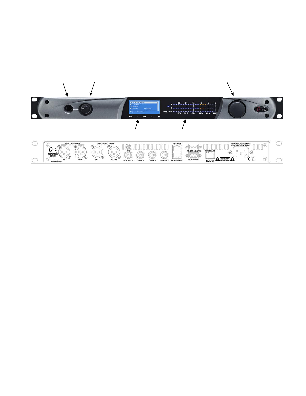
Refer to the following illustration for the location of the various controls and connectors associated with the installation:
Headphone Jack Headphone Level Control Jog Wheel
Main Menu / G/R Metering LCD Display Level Meters
1. Install the Omnia ONE in the equipment rack using at least two rack screws. If only two screws are used, they MUST
be installed in the bottom holes of the rack ears!
2. Connect AC power to the unit (there is no power switch!)
3. Connect the audio inputs that are appropriate for your installation.
4. Navigate to the Input/Output / Meter Select setting and select Input.
5. Navigate to the Input/Output / Input / Input Src setting and select the Analog, AES/EBU or Livewire input as
appropriate for your installation. If your audio source is providing an audio feed you should then see meter activity on
the LED bargraph meters.
6. While driving the inputs with typical program material at normal operating level, navigate back up to the Input/Output
/ Input menu (by highlighting and clicking on the “<-EXIT” option) and adjust the appropriate input Level control
until the peak-reading input bargraph meters are peaking up to at least –15 and up to –12 dBFS or a little higher.
7. Connect the audio outputs in a manner that is appropriate for your installation.
8. (FM Only) Navigate t o the Inp ut/Output / Output / FM Options submenu and ensure that the Pre-Emphasis, De-
emphasis and BS-412 settings are correct for your system and your location.
(AM Onl y) Navigate to the Input/Output / Output / AM Options submenu and e nsure that the Output Polarities, LPF
Frequency and Tilt adjustments are correct for your system and your location.
9. Navigate to the Input/Output / Output menu (All Styles) or Stereo Generator menu (FM Only) and adjust the
appropriate control so that the output level is correct for the equipment that follows the Omnia ONE.
10. Navigate back to the Main Menu, highlight Preset: and click. Rotate the jog wheel to display the preset you would
like to start with and click to select it.
The Omnia ONE Quick-Start Setup is now complete. Please read on to learn about some of the features that make the
Omnia ONE unique and for full details on proper installation and the operation of every control function.
Page 6

iv
Table Of Contents
Welcome to Omnia ONE! ........................................................................................................... i
Omnia ONE Quick-Start Setup .................................................................................................. iii
S A F E T Y I N S T R U C T I O N S .................................................................................... ix
HAZARD / WARNING LABELS ................................................................................................x
Manual Update Notification....................................................................................................... xii
Chapter-1: Installation ..................................................................................................................1
Pre-Installation Tasks ............................................................................................................1
About This Manual ................................................................................................................1
Omnia ONE Components......................................................................................................1
AC Power Environment ........................................................................................................1
Installation & Connections ...................................................................................................2
Rack Mounting & Grounding ............................................................................................. 2
AC Mains Power ................................................................................................................. 2
Rear Panel Connections ........................................................................................................3
Analog Audio Inputs and Outputs ...................................................................................... 3
A Note About Relative Phase: ............................................................................................ 3
Stereo Generator Connections (FM Style Only) ................................................................. 3
Composite Outputs 1 & 2 (BNC) (Active on FM Style Only) ........................................3
19 kHz Sync Output (BNC) (Active on FM Style Only).................................................4
SCA Input (BNC) (Active on FM Style Only) ................................................................4
Ethernet / Livewire Connection .......................................................................................... 5
RS-232 Modem Connection (DB-9M)* ............................................................................. 5
General Purpose Interface (GPI) (DB-9F)* ........................................................................ 6
Powering Up ...........................................................................................................................6
Chapter-2: Getting To Know Your Omnia ONE........................................................................7
The Omnia ONE User Interface ...........................................................................................7
Headphone Level Control ................................................................................................... 7
Level Meters & Processing Bargraphs ............................................................................... 7
Audio I/O Level Display ..................................................................................................... 8
Processing Meter Display ................................................................................................... 8
Main Menu .......................................................................................................................... 9
Using the Jog Wheel ......................................................................................................... 10
User Interface Tutorial – Input Source Selection and Peak Level Setting ....................... 11
Proper Setting of Input Levels .......................................................................................11
An Important Word about Time Delay .............................................................................12
Chapter-3: Getting the Sound You Want ..................................................................................13
FM Style ................................................................................................................................13
The Factory Presets ........................................................................................................... 13
Increasing Density/Loudness ............................................................................................ 14
Adding More Detail — When Loudness Isn’t the Last Word .......................................... 15
Air-Sound Equalization Changes ...................................................................................... 15
Thunder Bass .................................................................................................................... 16
Page 7

v
AM Style ...............................................................................................................................17
Using Omnia ONE AM with Early PWM Transmitters ................................................... 17
The Factory Presets ........................................................................................................... 17
Increasing Density/Loudness ............................................................................................ 19
Adding More Detail — When Loudness Isn’t the Last Word .......................................... 19
Air-Sound Equalization Changes ...................................................................................... 20
Thunder Bass .................................................................................................................... 20
Multicast/DAB Style ............................................................................................................21
Purpose .............................................................................................................................. 21
Sensus Technology: Audio Processingx3 .................................................................... 21
Overview ........................................................................................................................21
Codec Provisioning ........................................................................................................21
Omnia ONE Multicast and HD Radio ........................................................................22
So… what’s so smart about Sensus? ..........................................................................22
Loudness Processing and Codecs ..................................................................................... 23
A Word About Density, Clarity, and Intelligibility .......................................................... 23
Quality Versus Density ..................................................................................................... 23
Increasing Density/Loudness ............................................................................................ 24
Adding More Detail—When Loudness Isn’t the Last Word ............................................ 25
Equalization (EQ) Changes ............................................................................................... 25
Thunder Bass .................................................................................................................... 26
Coded Audio Considerations ............................................................................................ 26
Studio Pro Style ....................................................................................................................27
Purpose .............................................................................................................................. 27
Delay Throughput ............................................................................................................. 27
Equalization (EQ) Changes ............................................................................................... 27
Presets ............................................................................................................................... 28
Bass Enhancement ............................................................................................................ 28
Chapter-4: Main Menu Selections ..............................................................................................29
Preset ........................................................................................................................................ 29
Processing ................................................................................................................................ 29
Save Preset ............................................................................................................................30
Delete Preset .........................................................................................................................30
Rename Preset ......................................................................................................................31
<-Exit ................................................................................................................................ 31
Adjust Processing .................................................................................................................31
FM Style ........................................................................................................................... 32
<-Exit .............................................................................................................................32
Pre-processing ................................................................................................................33
Wideband AGC (Automatic Gain Control) ...................................................................33
Enhancers .......................................................................................................................34
Xover (Crossover) ..........................................................................................................35
Low Band AGC .............................................................................................................36
Mid Band AGC ..............................................................................................................36
Pres Band AGC (Presence Band AGC) .........................................................................36
High Band AGC .............................................................................................................36
Low Band Limiter ..........................................................................................................37
Page 8

vi
Mid Band Limiter ..........................................................................................................38
Presence Band Limiter ...................................................................................................38
High Band Limiter .........................................................................................................38
Bass Clipper ...................................................................................................................38
Mixer ..............................................................................................................................39
Clipper............................................................................................................................40
AM Style .......................................................................................................................... 41
Pre-processing ................................................................................................................42
Wideband AGC (Automatic Gain Control) ...................................................................42
Enhancers .......................................................................................................................43
Xover (Crossover) ..........................................................................................................44
Low Band AGC .............................................................................................................45
Mid Band AGC ..............................................................................................................45
Pres Band AGC (Presence Band AGC) .........................................................................45
High Band AGC .............................................................................................................46
Low Band Limiter ..........................................................................................................46
Mid Band Limiter ..........................................................................................................47
Presence Band Limiter ...................................................................................................47
High Band Limiter .........................................................................................................47
Bass Clipper ...................................................................................................................47
Mixer ..............................................................................................................................48
Clipper............................................................................................................................49
<-Exit .............................................................................................................................49
Multicast/DAB Style ....................................................................................................... 50
<-Exit .............................................................................................................................51
Pre-processing ................................................................................................................51
Wideband AGC (Automatic Gain Control) ...................................................................51
Enhancers .......................................................................................................................52
Xover (Crossover) ..........................................................................................................53
Low Band AGC .............................................................................................................54
Mid Band AGC ..............................................................................................................54
Pres Band AGC (Presence Band AGC) .........................................................................54
High Band AGC .............................................................................................................54
Low Band Limiter ..........................................................................................................55
Mid Band Limiter ..........................................................................................................55
Presence Band Limiter ...................................................................................................56
High Band Limiter .........................................................................................................56
Bass Clipper ...................................................................................................................56
Mixer ..............................................................................................................................57
Sensus .........................................................................................................................57
Final Limit .....................................................................................................................58
<-Exit .............................................................................................................................59
Page 9

vii
Studio Pro Style ............................................................................................................... 60
<-Exit .............................................................................................................................60
Pre-processing ................................................................................................................60
Wideband AGC (Automatic Gain Control) ...................................................................60
Enhancers .......................................................................................................................61
Xover (Crossover) ..........................................................................................................62
Low Band AGC .............................................................................................................63
Mid Band AGC ..............................................................................................................64
Pres Band AGC (Presence Band AGC) .........................................................................64
High Band AGC .............................................................................................................64
Low Band Limiter ..........................................................................................................64
Mid Band Limiter ..........................................................................................................65
Presence Band Limiter ...................................................................................................65
High Band Limiter .........................................................................................................65
Bass Clipper ...................................................................................................................65
Mixer ..............................................................................................................................66
Final Limit .....................................................................................................................67
<-Exit .............................................................................................................................67
Input/Output ........................................................................................................................69
Mtr Select (Meter Select) .................................................................................................. 69
Input .................................................................................................................................. 69
Output ............................................................................................................................... 71
FM Options (FM Style Only) ........................................................................................72
AM Options (AM Style Only) .......................................................................................74
Livewire ............................................................................................................................ 77
Stereo Generator (FM Style Only) .................................................................................... 77
Bypass ............................................................................................................................... 78
Save IO Config ................................................................................................................. 79
Load IO Config ................................................................................................................. 79
Delete IO Config ............................................................................................................... 80
Rename IO Config ............................................................................................................ 80
<-Exit ................................................................................................................................ 80
Administrative ......................................................................................................................80
About................................................................................................................................. 80
Contrast ............................................................................................................................. 80
Network Configuration ..................................................................................................... 80
Reboot ............................................................................................................................... 81
Security ............................................................................................................................. 81
<-Exit ................................................................................................................................ 81
Lock Front Panel..................................................................................................................82
Unlocking the Front Panel ................................................................................................ 82
Page 10

viii
Appendix A: Performance Specifications ..................................................................................83
Omnia ONE FM ...................................................................................................................... 83
Omnia ONE AM ..................................................................................................................... 87
Omnia ONE Multicast/DAB & Studio Pro........................................................................... 90
Appendix B: Troubleshooting/Service/Warranty .....................................................................93
Diagnostics and Error Messages.........................................................................................94
Electrical and mechanical safety note! ...............................................................................95
Narrowing down problems .................................................................................................95
Obtaining Service .................................................................................................................96
Via the World Wide Web ................................................................................................. 96
Via E-Mail ........................................................................................................................ 96
Via Phone & Mail (USA and non-European Countries) .................................................. 96
Warranty ..............................................................................................................................97
Appendix C: Remote Control and Software Update Procedure ............................................99
Remote Control ....................................................................................................................99
Remote ............................................................................................................................ 100
Preset Tab.....................................................................................................................101
Processing Tab .............................................................................................................101
In Tab ...........................................................................................................................102
Out Tab ........................................................................................................................103
IO Tab ..........................................................................................................................103
Encode Tab (FM Style Only) .......................................................................................103
Livewire .......................................................................................................................... 104
File Transfer .................................................................................................................... 105
Preset File Transfer ......................................................................................................105
I/O Configuration File Transfer ...................................................................................106
Trigger Scripts ................................................................................................................ 106
Software Update Procedure ..............................................................................................107
Special Notes: ................................................................................................................. 107
Page 11

ix
S A F E T Y I N S T R U C T I O N S
1. Read All Instructions. All safety and operating
instructions must be read before operating the
product.
2. Retain All Instructions. All safety and operating
instructions must be retained for future reference.
3. Heed All Warnings. All warnings on the product
and those listed in the operating instructions must
be adhered to.
4. Follow All Instructions. All operating and product
usage instructions must be followed.
5. H ea t. This product must be situated away from any
heat sources such as radiators, heat registers, stoves,
or other products (including power amplifiers) that
produce heat.
6. Ventilation. Slots and openings in the product are
provided for ventilation. They ensure reliable
operations of the product, keeping it from
overheating. These openings must not be blocked
nor covered during operation. This product should
not be placed into a rack unless proper ventilation is
provided through following the manufacturer's
installation procedures.
7. Water and Moisture. Do not use this product near
water – for example; near a bath tub, wash bowl,
ki tc he n si nk o r laundry tub; in a wet basement; or
near a swimming pool or the like.
8. Attachments. Do not use any attachments not
recommended by the product manufacturer as they
may cause hazards.
9. P ow er So ur c es . This product must be operated from
the type of power source indicated on the marking
label and in the installation instructions. If you are
not sure of the type of power supplied to your
facility, consult your local power company.
10. Gr oun din g a nd Pol ari zat ion . This product is equipped
with a polarized AC plug with integral safety
ground pin. Do not defeat the safety ground in any
manner.
11. Po wer Cord Prote cti on. Power supply cords must be
routed so that they are not likely to be walked on
nor pinched by items placed upon or against them.
Pay particular attention to the cords at AC wall
plugs and convenience receptacles, and at the point
where the cord connects to the product.
12. Lightning. For added protection for this product
during a lightning storm, or when it is left
unattended and unused for long periods of time,
unplug it from the AC wall outlet. This will prevent
damage to the product due to lightning and power
supply surges.
13. Overloading. Do not overload AC wall outlets,
extension cords, or integral convenience outlets as
this can result in a fire or electric shock hazard.
14. Object and Liquid Entry. Never push objects of any
kind into this product through openings as they may
touch dangerous voltage points or short out parts
that could result in a fire or electric shock. Never spill
liquid of any kind into the product.
15. Accessories. Do not place this product on an unstable
cart, stand, tripod, bracket, or table. The product
may fall, causing serious damage to a child or adult,
and serious damage to the product. Any mounting of
the product needs to follow manufacturer's
installation recommendations.
16. A Pro duc t an d C art Co mbi nat ion should be moved with
care. Quick stops, excessive force, and uneven
surfaces may cause the product and the cart
combination to overturn.
17. Servicing. Refer all servicing of the product to
qualified service personnel.
18. D am ag e R eq u ir in g S er v ic e. Unplug this product from
the AC wall outlet and refer servicing to qualified
service personnel under the following conditions:
• When the AC plug is damaged.
• If liquid has been spilled or objects have fallen into
the equipment.
• If the product has been exposed to rain or moisture.
• If the product does not operate normally (following
operating instructions).
• If the product has been dropped or damaged in any
way.
• When the product exhibits a distinct chang e in
performance. This indicates a need for service.
19. R ep la c em en t P ar ts . When replacement parts are
required, be sure the service technician has used
replacement parts specified by the manufacturer or
that have the same characteristics as the original
parts. Unauthorized substitutions may result in fire,
electric shock, or other hazards.
20. Safety Check. Upon completion of any repairs to this
product, ask the service technician to perform safety
checks to determine that the product is in safe
operating condition.
21. Cleaning. Do not use liquid cleaners or aerosol
cleaners. Use only a damp cloth for cleaning.
Page 12
x
HAZARD / WARNING LABELS
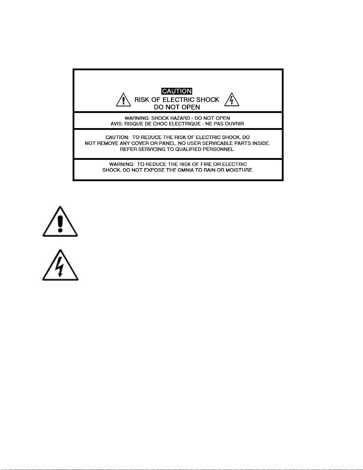
The Exclamation Point symbol, within an equilateral triangle, alerts the user to the
presence of important operating and maintenance (servicing) instructions in product
literature and instruction manuals.
The Lightning Flash With Arrowhead symbol, within an equilateral triangle, alerts
the user to the presence of non-insulated dangerous voltages within the product's
enclosure that may be of sufficient magnitude to constitute a risk of electric shock.
WARNING -- This equipment generates, uses, and can radiate radio frequency energy. If not
installed and used in accordance with the instructions in this manual it may cause interference to
radio communications. The device has been formally submitted for testing and found to comply
with the limits for a Class B computing device (pursuant to subpart J of Part 15 FCC Rules) and
has been designed to provide reasonable protection against such interference when operated in a
commercial environment. Operation of this equipment in a residential area may cause
interference, and the user and at his expense will be required to take any measures required to
correct interference.
CANADA WARNING – This digital apparatus does not exceed the Class B limits for radio
noise emissions set out in the Radio Interference Regulations of the Canadian Department of
Communications. Le present appareil numerique n'emet pas de bruits radioelectriques depassant
les limits applicables aux brouillage radioelectrique edicte par le ministere des Communications
de Canada.
Page 13
xi
CE CONFORMANCE – This device complies with the requirements of the EEC Council
Directives: 93/68/EEC (CE Marking); 73/23/EEC (Safety – low voltage directive); 89/336/EEC
(electromagnetic compatibility). Conformity is declared to those standards: EN50081-1,
EN50082-1.
LITHIUM BATTERY CAUTION – There is a danger of explosion if the internal
battery is replaced incorrectly or shorted. Replace the battery only with same or
equivalent type recommended by the manufacturer. Dispose of used batteries
according to the manufacturer's instructions.
USE OF SHIELDED CABLING – In order to conform to the CE requirements for
High Frequency radiation, shielded cables must be used for all audio and data
connections.
NOTE: When the unit is operated in an extremely high RF environment, it may be
helpful to connect cable shields to the XLR-connector terminal that connects cable
shield to chassis ground, not to pin 1. Additionally, a 0.01uF capacitor connected
between XLR pin-1 and the chassis terminal may be helpful in some instances.
RoHS COMPLIANCE – The RoHS Directive stands for "the restriction of the use of certain
hazardous substances in electrical and electronic equipment". This Directive bans the placing on
the European market of new electrical and electronic equipment containing more than agreed
levels of lead, cadmium, mercury, hexavalent chromium, polybrominated biphenyl (PBB) and
polybrominated diphenyl ether (PBDE) flame retardants. Omnia ONE FM is in compliance with
the EU RoHS Directive.
Page 14
xii
Manual Update Notification
Audio Processing – a unique art form that we take very seriously!
As part of our dedication to the science of audio processing we will continue to improve and
update the Omnia product and its documentation based on our ongoing research, real-world field
experience, and the valued input from our many thousands of loyal customers.
We strongly encourage our customers to visit our Omnia website for product enhancement
announcements, software updates, updated user manuals, and customer support bulletins.
The following URLs have been included for your convenience:
Manual Updates
http://www.omniaaudio.com/support/manuals.htm
Frequently Asked Questions (FAQ)
http://www.omniaaudio.com/support/faq.htm
Tech Tips & Support Bulletins
http://www.omniaaudio.com/tech/tips.htm
Software Upgrades & Remote Software
http://www.omniaaudio.com/support/updates.htm
White Papers & Technical Discussions
http://www.omniaaudio.com/tech/default.htm
Page 15

1
Chapter-1: Installation
Pre-Installation Tasks
Please take a few minutes to read through this chapter before proceeding with the installation. This section offers
common procedures for installing your new Omnia ONE processor.
About This Manual
This manual is now written to cover all 4 styles of the Omnia ONE. This chapter will cover o n ly general installation
topics. Topics unique to a specific style are covered in style-specific sections within Chapters 3 and 4. The latest
version of this manual is always available for download from the Omnia website here:
http://www.omniaaudio.com/support/manuals.htm
Omnia ONE Components
By now, you’ve unpacked the shipping carton to gain access to this manual. Now is the time to inspect the Omnia
ONE unit and its shipping carton for any signs of shipping damage. Such damage must be reported to your carrier
for any claims. The Omnia ONE shipping box includes the following components:
Omnia ONE processor.
Omnia ONE Operating Manual.
Warranty Registration Card. (Please complete the form and return/FAX it to Telos/Omnia)
Two IEC Power Cords, one of the USA/Canada style, and one of the Euro style.
One each Male and Female XLR to StudioHUB RJ45 adaptor cables.
AC Power Environment
The Omnia ONE subsystem is a DSP-based microcomputer, and therefore requires reasonably clean AC power, just
as any modern computer system does. And even though the Omnia ONE power supply is equipped with robust AC
transient suppression, we recommend that an “online” style (non-switching type) Uninterruptible Power Supply
(UPS) with transie nt surge suppression be employed.
At transmitter sites there can be heavy transients on the power lines as well as significant surges introduced into the
power system by frequent lighting strikes. These are unwelcome power line events and can damage even the most
robust equipment. Therefore you should give the AC power environment and installation practices thorough
consideration before plugging in the O mnia ONE (or any other microcomputer-based equipment).
A White Paper by one of our Support Engineers can be found on the Telos Systems website at the URL listed below.
It details proper grounding and contains links to some surge suppression products for both the power mains and the
often-neglected telephone, Ethernet and ISDN line connections that can (and do) conduct powerful surges into the
equipment.
http://www.telos-systems.com/techtalk/surge.htm
Page 16
2
Installation & Connections
Rack Mounting & Grounding
The Omnia ONE requires one RU (1.75" [44.45 mm]) of rack space. Rack mount the unit using four rack screws. If
only two screws are going to be used, they should be in the bottom holes in the Omnia front panel. No other twoscrew mounting arrangement will prevent distortion of the front panel!
Adequate ventilation should be provided, and it is always good engineering practice to allow one blank rack space
immediately above and below the Omnia, especially if equipment generating significant heat is located below the
unit. You may install 1RU (1.75") vented or solid rack panels to fill these spaces.
The processor should be installed into a properly grounded 19" equipment rack.
It is a good idea, especially at transmitter sites, to run a separate ground strap or braid from the Omnia ONE’s
chassis to a solid rack or station ground point. Although no separate ground lug is provided, the end of the strap or
braid can be clamped under the Omnia’s top cover using the Omnia’s existing top cover screws.
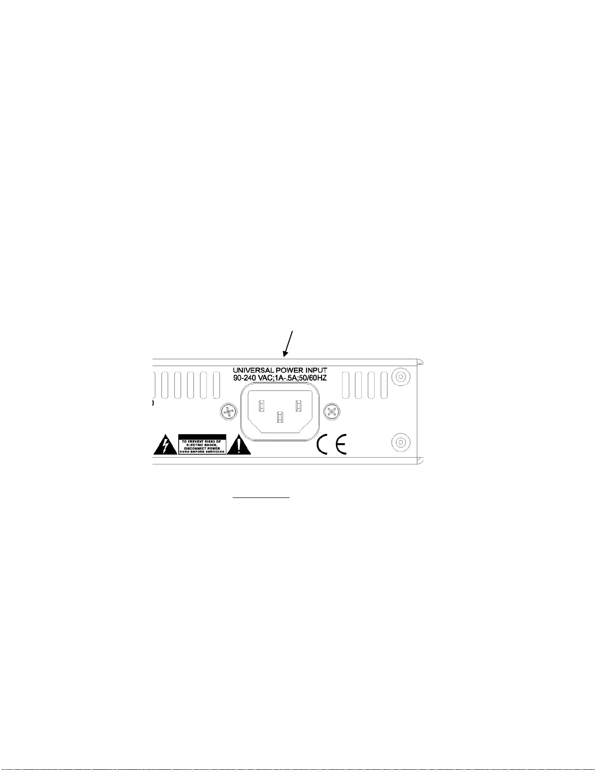
AC Mains Power
AC Power Connection
Omnia ONE utilizes an un-switched EMI-filtered IEC power-entry module.
Omnia ONE’s automatic voltage–sensing, high-efficiency switching power supply allows it to operate on AC mains
voltages from 100 to 240 VAC and from source frequencies of either 50 or 60 Hz.
In the USA or Canada, plug the provided IEC type AC power cord into the unit and then into a grounded AC outlet.
Outside of the USA you must use the appropriate power cord that complies with local electrical regulations.
After power is first applied to the Omnia ONE, the LCD screen, the “in” and “out” LED’s and the rightmost
segments of the LED bargraph meters should light.
After about 20 seconds the LCD screen should show “Omnia ONE” and at about 30 seconds the Main Menu should
appear. Once the Main Menu appears the unit is ready for use.
Page 17
3
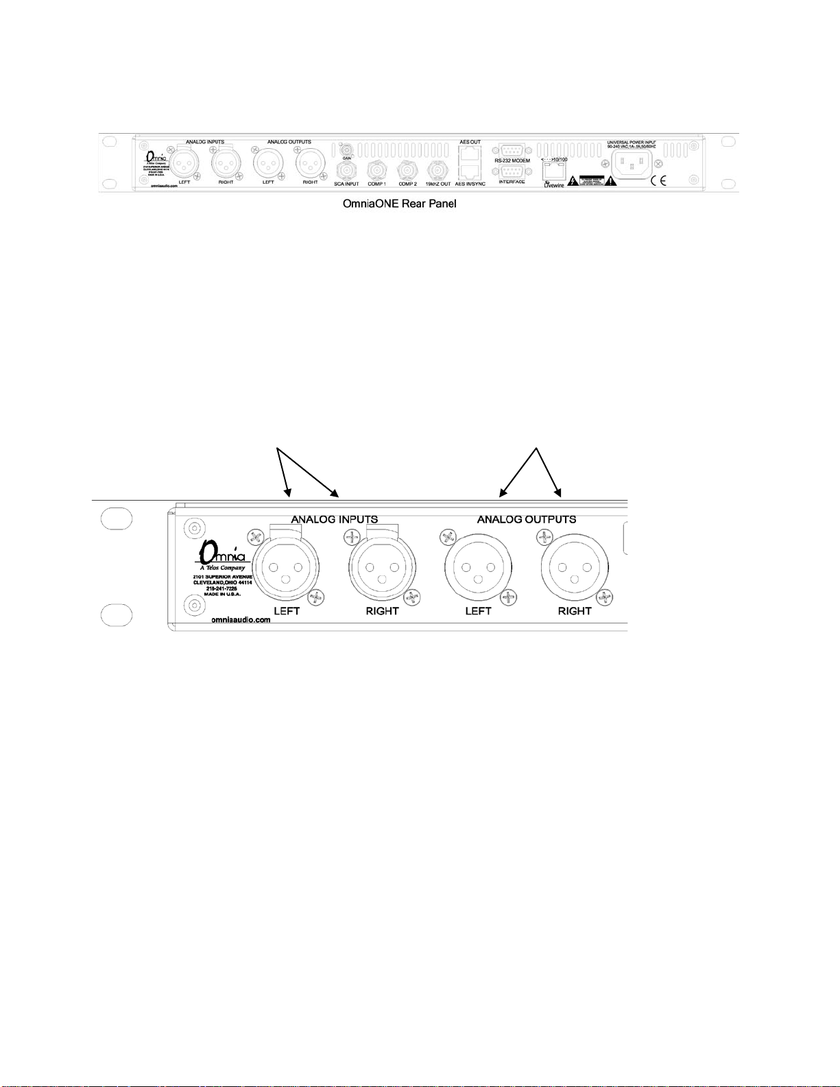
Rear Panel Connections
Analog Audio Inputs and Outputs
Balanced XLR-type connectors are used for the analog audio. Both analog and digital input sources may be
connected simultaneously, however, only the input source that has been selected is active. Analog/Digital/Livewire
Input source selection is done through the “Input Src” (Input Source) software parameter setting in the Input
submenu of the Input/Output menu.
All outputs are active simultaneously.
The stereo analog inputs Individual Left and Right
are designed for standard analog outputs are available
+4dBu balanced signals. on two male XLR jacks.
Pin 2 is Hot. Pin 2 is Hot.
A Note about Relative Phase:
If the relative phase of your installation (including the Omnia ONE) differs fro m tha t o f your existing sys tem, your
anno uncers may fee l that they sound “weird” in their head phones. If this occurs, then the relative phase of the
processor is 180 degrees from what your air talent is used to. To remedy this, you can either reverse the polarity of
both of the analog inputs or simply change the “Invert” setting to [Both] in the Input submenu of the
Input/Output m e n u.
Stereo Generator Connections (FM Style Only)
Four standard female BNC connectors comprise the Omnia ONE’s stereo generator connections.
There are two composite MPX outputs with independent software level controls, one SCA input with level adjust
trimpot and one 19 kHz pilot sync output.
Composite Outputs 1 & 2 (BNC) (Active on FM Style Only)
These two low impedance outputs (Composite 1 and Composite 2) are each capable of driving up to 100 feet of
RG-58A/U coax cable. The output levels are individually adjustable so the unit can operate as a “composite
DA” to drive a variety of equipment. The output levels and other stereo generator settings are set through
Page 18
4
software parameters in the Stereo Generator submenu of the Input/Output menu. An internal jumper sets the
output impedance to either 5 ohms (the factory setting) or 75 ohms. The default setting is appropriate for the
vast majority of exciter connections. However, in the event that a higher source impedance is required, a jumper
can be moved (one for each composite output) on the motherboard to change the source impedance to 75 ohms .
For reference, JP10 is for Composite #1, and JP9 is for Composite #2.
19 kHz Sync Output (BNC) (Active on FM Style Only)
This TTL-level 19 kHz square wave output can be used as the reference signal for mo s t RDS or SCA generators
that operate at 57 kHz or other multiple of the 19 kHz pilot frequency. This Sync output is phase and frequency
locked to the stereo pilot. When this signal is used to synchronize an external SCA or RDS generator, this
locking assures that no difference frequencies exist which may cause intermodulation components between the
pilot and the SCA signal.
SCA Input (BNC) (Active on FM Style Only)
Any SCA or RDS signal above 53 kHz can be added to the composite outputs of the Omnia ONE by connecting
the signal to the SCA INPUT connector. The SCA signal is mixed in the analog domain directly into both
composite outputs. A high-pass filter on the SCA input provides SCA to main-channel crosstalk protection. The
SCA injection level can be adjusted using the Gain trimpot. See Page 77 for details.
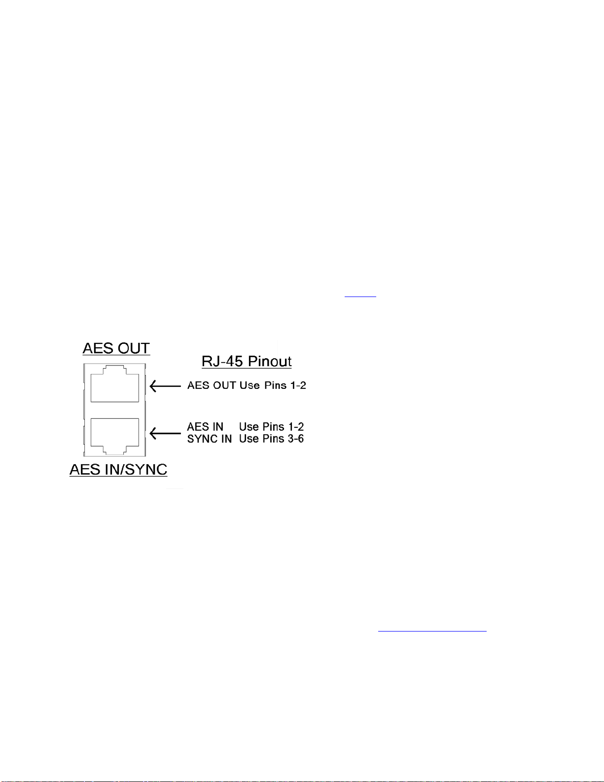
AES/EBU Digital Input, AES/EBU External Sync Input, and AES/EBU Output
(GREEN Male XLR)
(GREEN Female XLR)
(RED Female XLR)
The digital AES/EBU (AES-3) inputs (IN and EXT. SYNC) use industry-familiar RJ-45 connectors and utilize the
StudioHUB+ wiring standard1. They accept any sampling rate between 32kHz and 96kHz. No user adjustment of the
sample rate is necessary on the AES-3 input as a high-quality digital sample rate converter is built in.
There is one AES-3 output on a standard RJ-45 connector that provides either an internally generated output sample
rate of 48 kHz or the sample rate can be locked to an external AES/EBU signal applied to pins 3 & 6 of the the AES
IN / SYNC IN connector or to the AES/EBU input signal. These options are selectable using the “Samp. Rate”
setting in the Output submenu of the Input/Output menu.
Note: The analog and digital outputs are active simultaneously.
1
More information about the StudioHUB+ wiring scheme can be found at: http://www.studiohub.com/
For your convenience, two XLR adaptor cables are supplied with the unit. The male XLR lead with the GREEN
shrink tubing is used for AES OUT. The male XLR lead with the RED shrink tubing is not used.
The female XLR lead with the GREEN shrink tubing is used for AES IN and the female XLR lead with the RED
shrink tubing is used for AES EXTERNAL SYNC IN.
Page 19
5
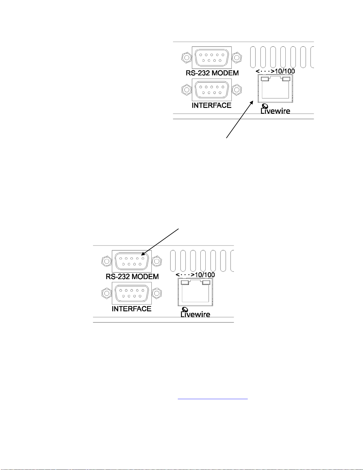
Ethernet / Livewire Connection
The RJ-45 10BaseT / 100BaseT Ethernet / Livewire
I/O jack can be used simultaneously for both
TCP/IP based remote control of your Omnia ONE
and audio input/output to your existing Livewire
network.
Ethernet 10BaseT/100BaseT Remote and Livewire I/O
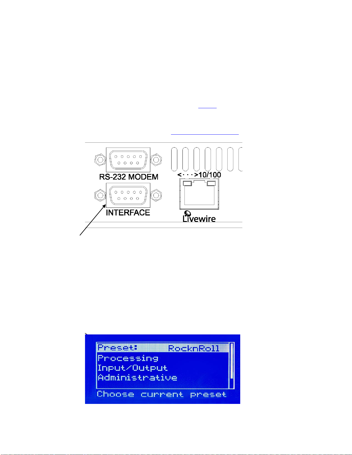
RS-232 Modem Connection (DB-9M)*
This DB 9-male connector can be used to connect an external dialup modem for a bi-directional computer remote
control connection.
1
NOTE: This connector is for a remote control external modem connection only. Please see Appendix B for
information on how to use a terminal program along with an internal RS-232 connector for troubleshooting
purposes.
RS-232 Modem Port
NOTE: You must use a standard straight-through serial cable and not a null modem cable when connecting the RS-
232 connector of the Omnia and the external modem. Typically this would be 9-pin to 25-pin cable. (External
mode ms traditio nally have 25 pin co nnectors in "DCE" co nfiguration. The Omnia ONE has a 9 pin in "DTE"
configuration, so the standard 9-pin to 25-pin cable will wo rk ).
1
The setup and operation of the Omnia Remote Control application is covered in detail in Appendix C.
*Please note that the RS-232 Modem functionality is not yet implemented in the current software but will be
available with a free downloadable software update. Please check the Omnia website for new software
announcements, download links and manual updates at: http://www.omniaaudio.com/
Page 20
6
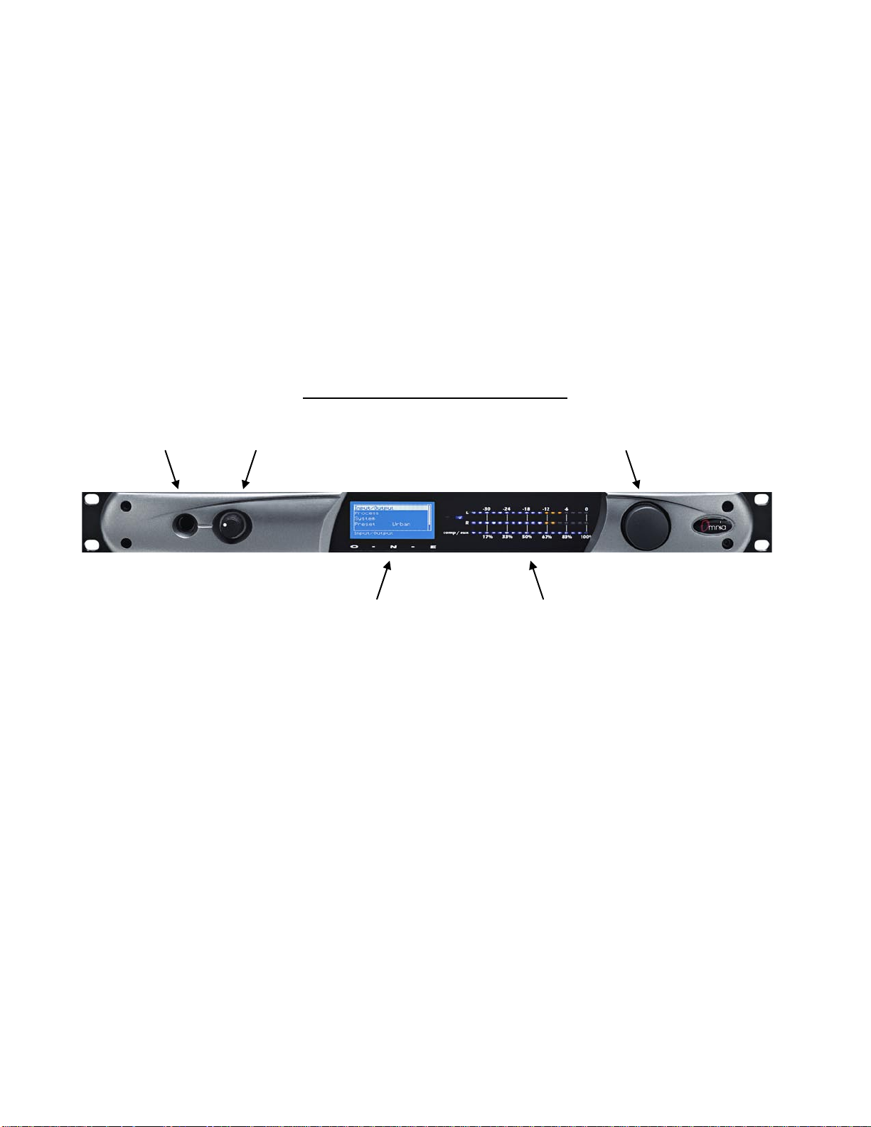
General Purpose Interface (GPI) (DB-9F)*
This DB 9-female connector serves as a four-input, optoisolated interface to the Omnia's internal Trigger Script
functions*. Four of the pins are “trigger” inputs, one is a bias voltage input, one is a +5V power output, and the
remaining three are “ground.” The trigger inputs can be used to dynamically alter the Omnia ONE’s operation in
response to logic transitions on the interface connection. Virtually any parameter of the Omnia can be controlled
using the Trigger Scripts.
The Trigger Script Interface is a standard component of the Omnia ONE Remote Control application. Full details,
including connector pinout, are covered in Appendix C, starting on Page 99.
*Please note that the GPI and Trigger Script functionality are not yet implemented in the current software but will be
available with a free downloadable software update. Please check the Omnia website for new software
announcements, download links and manual updates at: http://www.omniaaudio.com/
DB-9M GPI “Interface” Connector
Powering Up
Now you are ready to power up the Omnia ONE for the first time.
Connect AC power to the unit using the appropriate supplied power cable for your location.
(There is no power switch!)
When the Omnia ONE is first powered on, audio will appear at the analog audio outputs in approximately ten
seconds. The AES/EBU and Livewire outputs also become usable at this time however full initialization of the
digital ports is not complete for several more seconds and a small audio glitch may be heard when the final sample
rate converter initialization is complete. Once the boot process is finished the following Main Menu will appear:
Page 21
7
Chapter-2: Getting To Know Your Omnia ONE
The Omnia ONE User Interface
N o w t hat your Omnia ONE is rack-mounted, connected to a program audio source, and turned on, you’re ready to
learn how to operate it! This chapter covers the Front Panel User Interface, your window into the Omnia ONE
processor.
A front panel jog-wheel with integral push switch, LED bargraph peak-reading level meters and a backlit LCD
display that is switchable between menu and AGC/Limiter metering screens make up the primary Omnia ONE User
Interface. The front panel menu access may be password protected to prevent unauthorized tampering with
processing or presets.
Omnia ONE Key Front Panel Features
Headphone Jack Headphone Level Control Jog Wheel
Main Menu / G/R Metering LCD Display Level Meters
Headphone Level Control
A standard ¼" TRS stereo headphone jack is located at the left side of the front panel and allows the processed
signal to be monitored. The Headphone volume level control is physically located to the right of the headphone jack.
The headphone amplifier itself is a high-headroo m design and is driven by its own hi gh quality D/A converter that is
independent of the analog XLR outputs. Therefo re level changes in ei ther output will not affe ct the o the r.
Level Meters & Processing Bargraphs
The top two of the three horizontal meters show digital sample-accurate peak representations of the left and right
channel input or output levels. Whether these bargraphs are displaying Input, Analog Output, AES/EBU Output or
Livewire Output levels is selectable from within the Input/Output menu. A front panel indicator confirms which
level view has been selected, Input or Output.
The bottom horizontal meter (marked “comp / aux”) displays the composite MPX level from the stereo generator
before the output level controls. (Active on FM Style Only)
Page 22
8
Audio I/O Level Display
Either input or output levels can be displayed on the top 2 (L & R) meters. The highest LED illuminated indicates
digital sample-accurate peak signal levels. The meters are calibrated in decibels below full scale digital (0 dBFS) in
2dB steps. 0 dBFS is the absolute maximum level in the digital domain. Levels from –34 dBFS to –14 dBFS are
displayed in blue, levels from –12 to –2 dBFS are displayed in yellow and 0 dBFS (the clipping point) is displayed
in red. The bottom meter displays the composite MPX signal level referenced to 100% modulation (FM Style Onl y).
Audio I/O Level Display
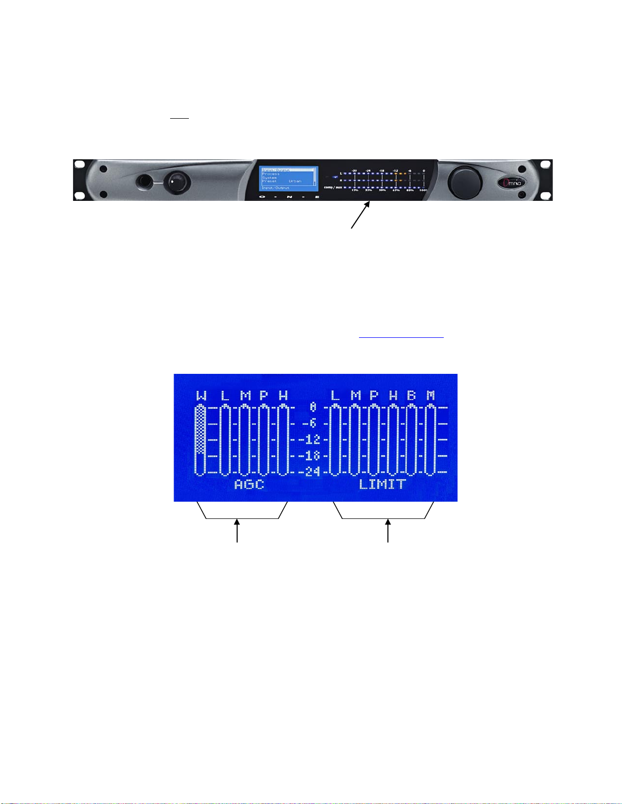
Processing Meter Display
In “Meter Display” Mode the vertical bargraphs show all of the processing activity (the amount of gain red uction) in
the AGC, Limiter and Clipper sections within the Omnia ONE. (varies with st yle) If the “Menu Display” is
currently showing on the Omnia ONE’s LCD screen, press and hold the jog-wheel for two seconds to switch to the
processing meter display as shown below.
To return to the Menu display, simply click the jog wheel once. (See “Using the Jog Wheel” on Page 10)
Processing Meter Display
AGC Meters Li miter/Clipper Meters
W…... Wide Band AGC L….. Low Band Limiter
L……. Low Band AGC M…. Mid Band Limiter
M…… Mid Band AGC P…... Presence Band Limiter
P…… Presence Band AGC H….. High Band Limiter
H…… High Band AGC B….. Bass Clipper
M…. Main Clipper (AM & FM Styles)
or F…..Final Limiter (MC & SP Styles)
Important Notes:
• A solid white bar will drop downward from the top to display the amount of gain reduction in each
processing band. The change from a solid bar to a checkerboard pattern indicates a “gated” condition
in that band.
Page 23
9
• The wideband AGC and four-band AGCs will recover to a resting gain setting which coincides with
the RTZ (Return To Zero) levels set for each band.
• The Clipper meters are peak reading, showing the maximum amount of clipping that occurred over
the past 30 milliseconds. The Main clipper meter (FM & AM Styles Only) will indicate higher
amounts of clipping on bright program material because the Main Clipper is operating on the preemphasized audio signal. This is normal and does not indicate the perceived amount of audio
distortion.
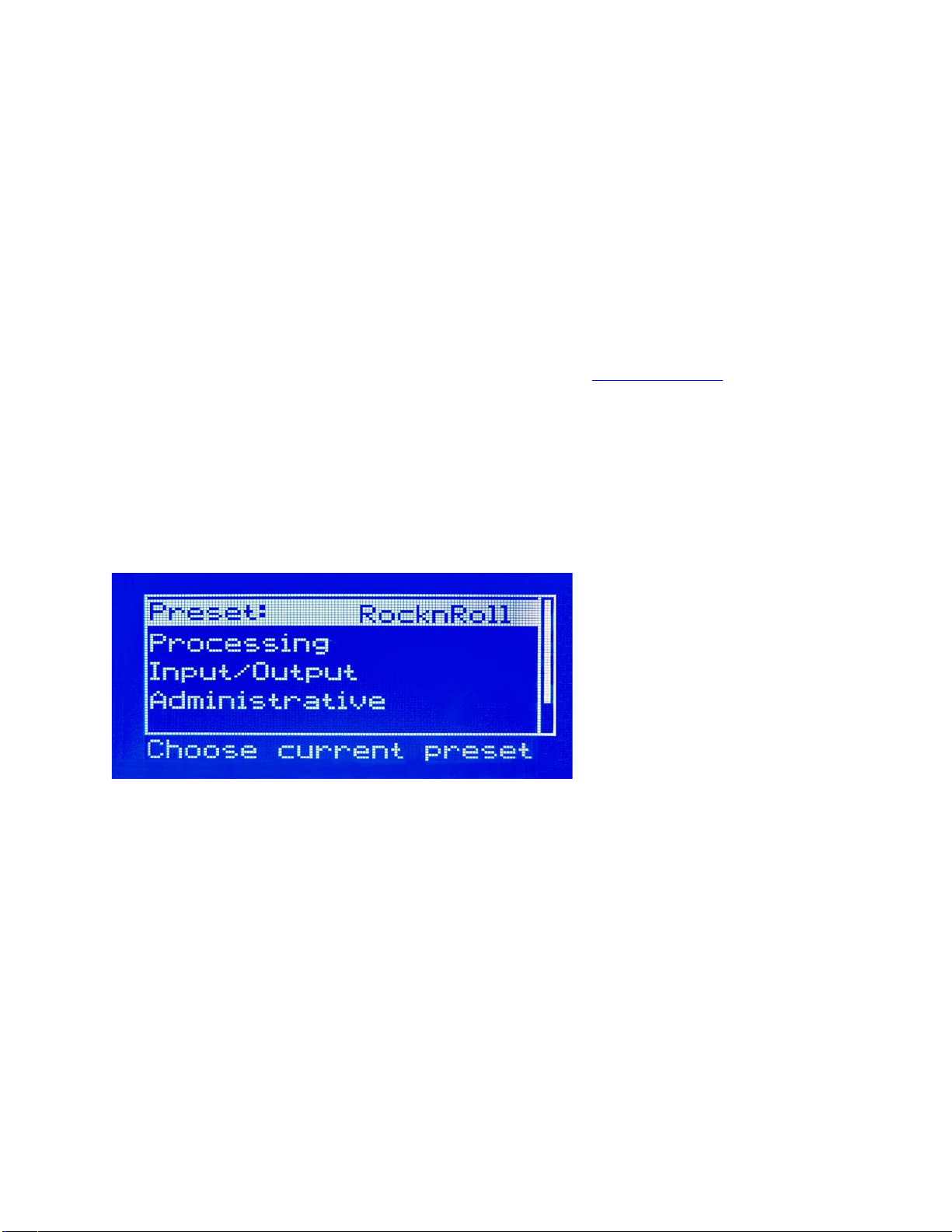
Main Menu
The Omnia ONE menu system has been designed to be intuitive and simple to use. Most operating parameters can
be found under one of the menu headings and sub-headings, allowing adjustments to be made quickly and with ease.
Rotating the jog-wheel sequentially highlights each menu item in turn. (See “Using the Jog Wheel” on Page 10)
When the jog wheel is pressed inward (clicked) while a menu item is highlighted it will open that item’s submenu.
Similar behavior occurs when selections are made within the various submenus.
To return to the previous level, rotate the jog wheel until <-Exit is highlighted and then press the jog wheel inward.
(Click) This wi ll return you to the next hi ghest level in the men u structure. N OTE: S ome of the longer menus have
an <-Exit option at the top of the menu as well as at the bottom.
The Omnia ONE Main Menu offers five selections:
• Preset
• Processing
• Input/Output
• Administrative
• Lock Front Panel (not visible in the above screenshot)
Page 24
10
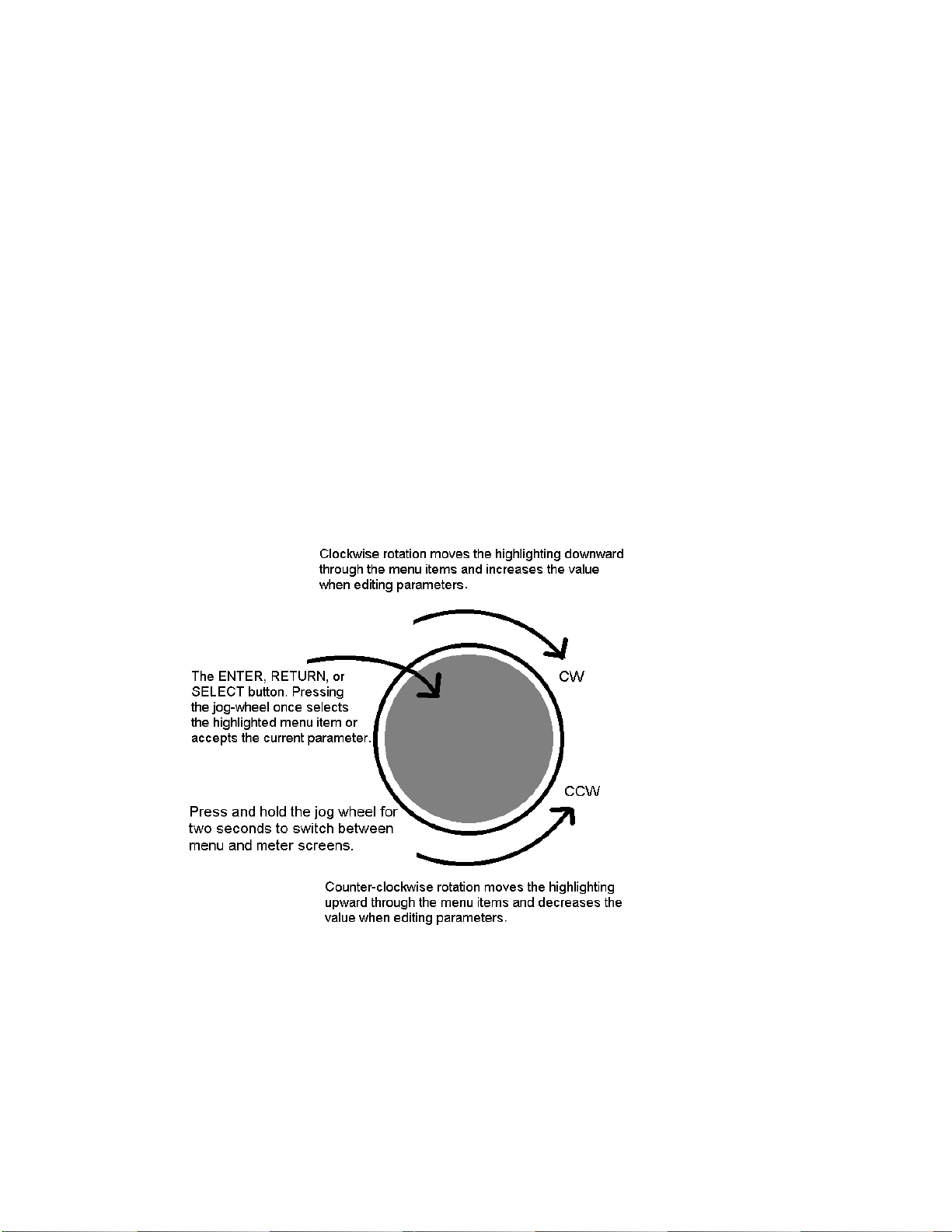
Using the Jog Wheel
The main user control for the Omnia ONE is the easy to use jog wheel with its integral push-switch. Using the
control is both intuitive and efficient, making it easy to navigate the menu structure of the Omnia ONE. Processing
changes and system adjustments can be quickly made with ease without having to remember multiple controls, their
positions, and what they do in each menu. The behavior of the Omnia ONE's menu system is consistent across pages
and is easy to learn. We believe that you will quickly become comfortable with how it works, and appreciate its
simplicity.
Clockwise rotation moves the highlighting in a menu downward and increases a value when editing parameters.
Counterclockwise rotation moves the highlighting in a menu upward and decreases a value when editing parameters.
Pr essing inward on the j og-wheel activates the Enter, Return or Select button function as follows:
Pr essing the jog-wheel inward once (also called “clicking”) selects the highlighted menu item or accepts the current
parameter value. Think of it as a vertical mouse button.
Pr essing and ho ldi ng the jog-wheel in for two seconds will switch the LCD screen to a display of the processing
meters so that the gain-reduction activity of the AGC and Limiter sections can be monitored.
Clicking once when the metering screen is displayed will return the display to the menu screen.
Page 25

11
User Interface Tutorial – Input Source Selection and Peak Level Setting
The following two exercises are a useful introduction to the user interface. Start from the Main Menu (as displayed
when the unit is first turned on ).
The first exercise changes a parameter selection (the Input Source selection):
Rotate the jog-wheel to highlight Input/Output.
Click the jog-wheel (push on the wheel once until a click is felt and release) to bring up the Input/Output
menu.
Rotate the jog-wheel to highlight Input and click.
Rotate the jog-wheel to highlight Input Src and click.
The factory default selection for Input Source is Analog. To change the input selection to AES/EBU digital
or Livewire, rotate the jog-wheel until [AES/EBU] or [Livewire] is displayed and click. If you are using
the analog inputs, rotate the jog wheel to display [Analog] and click to reselect the analog inputs.
To return to the top level of the Main Menu, rotate the jog-wheel to highlight <-EXIT and click. Repeat
until the top level (Main Menu) is reached. NOTE: Many of the Omnia ONE’s menus have an <-EXIT
selection at both the top and bottom of the menu.
The next exercise adjusts a parameter that uses a value (the analog master input level setting):
The Main Menu display should still be showing on the LCD screen. If not, click the jog-wheel to display it.
Highlight Input/Output and click.
Highlight Mtr Select, click, rotate the jog wheel until [Input] is displayed and click. This sets the first 2 LED
meters to monitor the Left and Right channel input levels.
Rotate the jog wheel clockwise to highlight Input and click.
Rotate the jog wheel to highlight Anlg Level and click the jog-wheel to select the control.
Rotate the jog-wheel CW to increase the input level. Rotate the jog-wheel CCW to decrease the input level.
This control adjusts both channels together in precise 0.5 dB steps. The gain in dB is shown to the right of the
“control.” Watch the Left and Right channel LED meters while adjusting per the following section b e l o w .
Proper Setting of Input Levels
With normal program audio levels applied, a correct input level setting will result in peak indications on the L & R
LED meters achieving –12 dBFS or a little higher (just into the yellow). This gain setting corresponds to system
headroom of about 12 dB. You may adjust the input level lower for more headroom if you wish. Setting the input
level for higher meter indications (less headroom) is strongly discouraged unless there is another level-control
device prior to the Omnia ONE that will keep the input levels from reaching the maximum digital level of 0 dBFS.
During nor mal operation, you sho uld neve r see the red “0” segments light.
Once the desired level setting is reached, click the jog-wheel to accept that value. This returns the jog-wheel
to Select Mode.
You may hi ghlight and click Right Trim to adjust its gain separately from the left channel if the input source
is not well balanced. In this mode the right channel gain can be adjusted over a range of plus and minus 3 dB
Page 26

12
relative to the gain setting of the left channel.
To return to the top level of the Main Menu, rotate the jog-wheel to highlight <-Exit and click. Repeat until
the top level (Main Menu) is reached.
All of the Omnia ONE’s software parameters are set in a similar fashion using the jog-wheel to scroll through menu
items. Clicking a highlighted item selects it; when that item is a control, the jog-wheel adjusts the value or level.
Clicking accepts the value or level and returns the jog-wheel to Select Mode.
Note: Altering any processing or gain parameter will instantly be reflected in a change in the Omnia ONE’s output
characteristics because adjustments occur in real time. Therefore any adjustments you make will be instantly heard
as they occur.
An Important Word about Time Delay
A question commonly a sked about Omnias is “How much time delay does it have?” The answer: “Not enough to
drive your DJ’s crazy!”
Certainly, there is reason for concern about the propagation delay through any digital transmission device, audio
processors included. We have measured the propagation time delay, the amount of time it takes for the audio signal
to travel from the analog input of Omnia ONE to the output at approximately 7.7ms for the FM Style when using
AES/EBU digital I/O, about 9.2ms when using analog I/O. This is enough for a slight voice-character coloration to
be audible to the person speaking, but usually not enough to be a problem for talent monitoring off the air.
The delay through the AM style is about 7.0ms(digital I/O) 8.5ms(analog I/O) and the delay through the Multicast
style is about 7.6ms using digital I/O and 9.1ms using analog I/O.
For the Studio Pro style, please see the “Delay Throughput” section in the Studio Pro Style section of Chapter 3. The
Studio Pro style was designed to minimize the delay throughput by allowing the bypassing of the Bass EQ and Final
Limiter sections.
If there is additional delay added to the system, such as that added by certain types of Digital STL, the cumulative
delay may become excessive and cause discomfort for the on-air talent.
Real-world tests conducted by Jeff Goode in Indianapolis determined that a slight echo may begin to be heard at 1015ms, and that anything above 25-30 ms is usually too annoying to talent for monitoring off-air.
Page 27

13
Chapter-3: Getting the Sound You Want
This chapter is divided into four sections, one each for the 4 different Omnia ONE styles, b eginning with the FM
style below.
Please refer to the section that applies to the style your Omnia ONE is running:
AM style: Page 17
Multicast/DAB style: Page 21
Studio Pro style: Page 27
FM Style
Welcome to the OMNIA ONE FM!
Don’t let the small single-rack sized package fool you! Omnia ONE’s new hardware platform allows us to pack
more power in its single rack space than the original Omnia.FM had in three!
This chapter explains generally how to alter the sound of the Omnia ONE FM factory presets, if desired, using the
controls explained in the Adjust Processing section of Chapter 4. Always go through all of the factory presets first,
regardless of their name, and start with the factory preset that is closest to the sound you are looking for.
The Factory Presets
If you go through and listen to all of the included factory presets, you should get a “feel” for them and find one to
start with that is close to the sound you are looking for.
Please keep in mind that the “formats” used to name the presets are only guidelines and are not engraved in stone.
We had to call them something!
Always make sure your input levels and modulation are set properly before beginning your evaluation of presets.
See Proper Setting o f I nput Levels on Page 11.
It is also important to adjust the main “Clipper Drive” control (described in Chapter 4) as low as possible for the
loudness you need for each preset that you try. This is because the “Clipper Drive” controls the primary tradeoff
between loudness and distortion.
The Omnia ONE FM is definitely capable of generating moment-to-mo ment loudne ss; it has the muscle. It also
maintains that famous Omnia clarity sought after by top programmers all over the world.
Omnia ONE FM is designed to minimize the impact of the quality vs. loudness trade-off.
If you believe that you’re in a loudness war and you feel a need to react, we can provide some suggestions that
should help. Conversely, if you have the luxury to strive for increased sound quality, we’ve got suggestions for you
too!
Omnia ONE FM has been designed to minimize the trade-offs between quality and loudness, and we recommend
that before starting the process of cranking it up, try to determine beforehand what sonic characteristics might be
lacking.
Page 28

14
In many cases it’s not just about increasing the drive to the limiters. Instead, it can be as non-intuitive as creating the
illusion of greater loudness by changing something simple – like a time constant. Sometimes the old adage of less is
more really applies!
Please give the following content some thought as it may assist you in developing an overall fine-tuning plan if you
feel changes beyond our factory presets are justified.
The trade-off between quality and loudness is primarily determined by how you choose to use the limiting and
clipping sections. While each function alone will generate “dial presence,” they each have different advantages, as
well as side effects.
When excessive limiting is us ed, inter modulation disto rtion is increased, making the audio sound “mushy” , a nd
“smeared.” The added short-term density can also cause the audio to be “tight”, “squashed”, or “dense.” The
dynamics” artifacts caused by excessive limiting might sound like “pumping,” “breathing.” The rule for limiting is
“a little goes a long way!”
When excessive clipping is used, harmonic distortion is increased. The audio level is in effect “running into the
brick wall.” Too much clipping can cause the audio to sound “broken-up,” “torn,” “rough,” or “edgy.” As might be
expected, the harder the limiters and clippers are driven, the louder the perceived audio. However, you are also
much more likely to encounter increased intermodulation and/or harmonic distortion.
The following sections are provided to assist you in designing the personality of your sound. As we said earlier,
there is no precise recipe for setting up audio processing because each application is different. However there are a
few basics that we can share with you that can help get you to where you want to go. Setting up processing for the
absolute best end product usually requires a concerted effort, some extended periods of critical listening, and making
a few intelligently chosen and subtle changes over time. It will be time and effort well spent, and all you need to
know up front is that you must:
Kno w your goals ( have a plan).
Take your time.
Always adjust deliberately and methodically.
Listen critically before making more adjustments.
Increasing Density/Loudness
Try to resist the temptation to crank up the aggressive processing sections. They will definitely add loudness but
usually at the cost of quality and intelligibility. Many times, just building a bit more RMS energy in the AGC
sections will do the trick.
The following a re some suggestio ns on where to be gin to make changes. For best results you should try them in the
order we have listed below.
Increasing loudness can be accomplished in five ways:
1. Alter the following parameters in the AGC:
Increase the Drive to the AGC sections.
Increase the Release settings to make the bands operate faster.
2. Modify the Multiband Limiter sections:
Increase the Drive to the Limiter section.
Increase the Release settings to make the bands operate faster.
Note that slowing the Attack time by using a lower setting can help make things sound more natural
when faster Release times are used. But be careful not to allow too many fast transients through to the
final limiter section.
3. Set the Hold threshold in each band to a lower value.
Page 29

15
4. Increase the Drive to the clipper sections.
5. A combination of all of the above (yes, it sounds crazy but it’s true)!
Always resist the temptation to make too many changes at once because it then becomes difficult to determine why,
or why not, an adjustment made the change you hear. It is better to make small adjustments to a small number of
controls at a time, and then listen to the result with a wide variety of program material. Once you have satisfactory
results in one area (like overall density) you can then move the focus to the next area that you feel needs more
tweaking.
Don’t be afraid to experiment with different styles of processing! Our presets are good starting points and are not
restricted to any particular format because of their name!
Adding More Detail — When Loudness Isn’t the Last Word
Now that we’ve “squashed the grape,” let’s look at what it takes to undo a heavily processed signal. Basically, just
reversing the procedures listed above will do the trick:
1. Reduce the Drive to the Clipper sections.
2. Back off on the influence of the Limiter stages:
• R ed uce the Overall Limiter Drive in the Xover.
• Reduce the Release times to slow down recovery.
• Raise the threshold of the Hold function.
3. Ease up on the AGC sections:
• Reduce the AGC Drive to the Wideband AGC and the Overall AGC Drive in the Xover.
• Reduce the Release times to operate slower.
Backing off the clipping sections first will allow the processing to retain a level of competitive loudness while
enhancing quality, and the overall dynamic texture will be affected less.
Start with reducing the Clipper amount in 0.5 dB steps. It’s surprising how much detail can be restored from just a
small change of 0.5 dB. Continue to reduce it until the loudness just falls off too much and then bring it back up a
little from there.
Generally, changes in the Clipper drives will have the most noticeable effect on quality, but it will also affect the
relative loudness level, too. You’ll need to find a “happy medium” that’s right for you.
Air-Sound Equalization Changes
Tailoring the shape of the overall audio spectrum can be done in three different sections:
1. The relative drive settings in the multiband AGC Xover me n u .
2. The relative Drive settings in the individual multiband Limiter menus.
3. The settings of the multiband limiter Mixer controls.
All three options will provide noticeable change in EQ. We suggest you use the first two listed options.
In either case, an EQ change is still followed by a dynamically controlled stage. Therefore any excessive EQ change
can be 'undone' by the subsequent AGC or Limiter.
Page 30

16
The last option, adjusting the Mixer, is designed to provide a final minor trim to the spectrum. If you've noticed that
we calibrated these controls in 0.10 dB steps, then you know what we mean when we say these controls are for fine
trim!
Since this stage is after all of the dynamic AGC and Limiting, a radical change in level in the Mixer will result in
additional and possibly excessive final limiting or clipping distortion of audio in that band. We suggest that changes
implemented here be limited to no more than about 1.0 dB. Naturally, the decrease in mix level can be done to any
desired amount.
Thunder Bass
Omnia ONE FM has the power to shake the walls with low end! If your source material has it, Omnia ONE FM can
expose that deep bass and do it with muscle! Tailoring Thunder Bass for more dominance is simple, and is done by
adjusting the following parameters and in the order listed:
1. Increase the amount of Bass boost in the Enhancers section.
2. Increase the Drive to the Low Frequency Limiter.
3. Increase the Release setting in the Low Frequency Limiter.
4. Increase the Drive to the Bass Clipper.
Just as in the section on ‘overdoing’ processing, again moderation is the key. If all of the above changes are made in
unison there is a possibility of severe low frequency buildup. This would unbalance the audio spectrum and produce
the ill usion of “lost” presence and high frequencies.
Generally, an increase in the Bass boost alone will provide a sufficient enhancement to the low end. Bass
adjustments should typically be done after selecting the preset you wish to use.
Page 31

17
AM Style
Welcome to the OMNIA ONE AM!
Don’t let the small single-rack sized package fool you! Omnia ONE’s new hardware platform allows us to pack
more power in its single rack space than the original Omnia had in three!
This chapter explains generally how to alter the sound of the Omnia ONE AM using the factory presets, and if
desired, using the controls explained in the Adjust Processing section of Chapter 4, to alter those presets and create
custom user presets.
Using Omnia ONE AM with Early PWM Transmitters
Certain PWM (Pulse Width Modulation) transmitter designs may exhibit a condition that can be exaggerated by the
extremely dense output of the Omnia. This condition is often referred to as the “cliff effect”.
These transmitters have a hard time dealing with linear response to high negative modulation levels and may show a
runaway condition when called upon to produce heavy negative modulation approaching 100 percent.
This effect can be seen by applying a steady 1 kHz tone to the transmitter at slightly less than 95 percent negative
modulation. Observe the modulation monitor closely as you slowly advance the modulation level to 100 percent.
If you notice a sudden jump to 100 percent without being able to first get to 97, 98 or 99 percent then you are
experiencing "cliff effect."
Due to the high processing power of the Omnia, this can result in over the air distortion not caused by the Omnia
itself.
The simple solution is to operate the Omnia so that negative peaks never exceed 90 to 95 percent modulation. You
will not notice any significant loss of level but will notice a much cleaner and less fatiguing sound. You may of
course make up this modulation loss by operating the Omnia with a slight amount of asymmetric output to achieve
100 percent or more on positive peaks.
You will also find that limiting negative modulation to less than 95 percent will allow much more aggressive
settings on the Omnia without audible distortion.
Furthermore, the design of the average AM receiver can cause noticeable distortion without any added loudness
when dense negative modulation exceeds 95 percent from any modern transmitter. So keeping your negative
modulation below 95% may be a good idea, regardless of the presence of the “cliff effect” in your transmitter.
The Factory Presets
If you go through and listen to all of the included factory presets, you should get a “feel” for them and find one to
start with that is close to the sound you are looking for.
Please keep in mind that the “formats” used to name the presets are only guidelines and are not engraved in stone.
We had to call them something!
Always make sure your input levels and modulation are set properly before beginning your evaluation of presets.
See Proper Setting o f I nput Levels on Page 11.
It is also important to adjust the main “Clipper Drive” control (described in Chapter 4) as low as possible for the
loudness you need for each preset that you try. This is because the “Clipper Drive” controls the primary tradeoff
between loudness and distortion.
Because many of our customers have been asking for an “in your face” preset for AM talk and sports shows, we
have designed several talk/sports presets that really punch it up. We also were asked for presets that would sound
Page 32

18
something like a “60’s – early 70’s” densely processed Top 40 music station, so we designed the OLDIESHEAVY
preset for that. There are several other less aggressive presets available for AM music formats such as
NOSTALGIA and JAZZ. There is also a softer CLASSICAL preset, which provides “AM type enhancement”,
but less dense processing for music as well as less aggressive talk. And finally there are the “MEDIUM” presets that
could be good starting points if you want a somewhat processed, but not too aggressive sound.
If you don’t need all of the processing power of the more aggressive “out of the box” presets, you still may wish t o
start with one of them and back it d own somewha t r ather than starting “softer” and cranking it up, as has been
“tradition”.
Please note that if you do choose to use the most aggressive presets (such as FLAMETHROW) to their maximums,
yo u r entire AM audio chain needs to be pristine. The STL needs to be as transparent as the proverbial “short piece of
wire” and the transmitter / antenna s y s tem should be as “state of the art” as possible for maximum benefit.
The Omnia ONE AM is definitely capable of generating moment-to-moment loudne ss; it has the muscle. It also
maintains that famous Omnia clarity sought after by top programmers all over the world.
Omnia ONE AM is designed to minimize the impact of the quality vs. loudness trade-off.
If you believe that you’re in a loudness war and you feel a need to react, we can provide some suggestions that
should help. Conversely, if you have the luxury to strive for increased sound quality, we’ve got suggestions for you
too!
Omnia ONE AM has been designed to minimize the trade-offs between quality and loudness, and we recommend
that before starting the process of cranking it up, try to determine beforehand what sonic characteristics might be
lacking.
In many cases it’s not just about increasing the drive to the limiters. Instead, it can be as non-intuitive as creating the
illusion of greater loudness by changing something simple – like a time constant. Sometimes the old adage of less is
more really applies!
Please give the follo wing content some thought as it may assist you in developing an overall fine-tuning plan if you
feel changes beyond our factory presets are justified.
The trade-off between quality and loudness is primarily determined by how you choose to use the limiting and
clipping sections. While each function alone will generate “dial presence,” they each have different advantages, as
well as side effects.
When excessive limiting is us ed, inter modulation disto rtion is increased, making the audio sound “mushy” , a nd
“smeared.” The added short-term density can also cause the audio to be “tight”, “squashed”, or “dense.” The
dynamics” artifacts caused by excessive limiting might sound like “pumping,” “breathing.” The rule for limiting is
“a little goes a long way!”
When excessive clipping is used, harmonic distortion is increased. The audio level is in effect “running into the
brick wall.” Too much clipping can cause the audio to sound “broken-up,” “torn,” “rough,” or “edgy.” As might be
expected, the harder the limiters and clippers are driven, the louder the perceived audio. However, you are also
much more likely to encounter increased intermodulation and/or harmonic distortion.
The following sections are provided to assist you in designing the personality of your sound. As we said earlier,
there is no precise recipe for setting up audio processing because each application is different. However there are a
few basics that we can share with you that can help get you to where you want to go. Setting up processing for the
absolute best end product usually requires a concerted effort, some extended periods of critical listening, and making
a few intelligently chosen and subtle changes over time. It will be time and effort well spent, and all you need to
know up front is that you must:
Know your goals (have a plan).
Take your time.
Always adjust deliberately and methodically.
Page 33

19
Listen critically before making more adjustments.
Increasing Density/Loudness
Try to resist the temptation to crank up the aggressive processing sections. They will definitely add loudness but
usually at the cost of quality and intelligibility. Many times, just building a bit more RMS energy in the AGC
sections will do the trick.
The following a re some suggestio ns on where to be gin to make changes. For best result s you shoul d try them in the
order we have listed below.
Increasing loudness can be accomplished in five ways:
1. Alter the following parameters in the AGC:
a. Increase the Drive to the AGC sections.
b. Increase the Release settings to make the bands operate faster.
2. Modify the Multiband Limiter sections:
Increase the Drive to the Limiter section.
Increase the Release settings to make the bands operate faster.
Note that slowing the Attack time by using a lower setting can help make things sound more natural when
faster Release times are used. But be careful not to allow too many fast transients through to the final
limiter section.
3. Set the Hold threshold in each band to a lower value.
4. Increase the Drive to the clipper sections.
5. A combination of all of the above (yes, it sounds crazy but it’s true)!
Always resist the temptation to make too many changes at once because it then becomes difficult to determine why,
or why not, an adjustment made the change you hear. It is better to make small adjustments to a small number of
controls at a time, and then listen to the result with a wide variety of program material. Once you have satisfactory
results in one area (like overall density) you can then move the focus to the next area that you feel needs more
tweaking.
Don’t be afraid to experiment with different styles of processing! Our presets are good starting points and are not
restricted to any particular format because of their name!
Adding More Detail — When Loudness Isn’t the Last Word
Now that we’ve “squashed the grape,” lets look at what it takes to undo a heavily processed signal. Basically, just
reversing the procedures listed above will do the trick:
1. Reduce the Drive to the Clipper sections.
2. Back off on the influence of the Limiter stages:
• Reduce the Overall Limiter Drive in the Xover.
• Reduce the Release times to slow down recovery.
• Raise the threshold of the Hold function.
3. Ease up on the AGC sections:
• Reduce the AGC Drive to the Wideband AGC and the Overall AGC Drive in the Xover.
• Reduce the Release times to operate slower.
Page 34

20
Backing off the clipping sections first will allow the processing to retain a level of competitive loudness while
enhancing quality, and the overall dynamic texture will be affected less.
Start with reducing the Clipper amount in 0.5 dB steps. It’s surprising how much detail can be restored from just a
small change of 0.5 dB. Continue to reduce it until the loudness just falls off too much and then bring it back up a
little from there.
Generally, changes in the Clipper drive will have the most noticeable effect on quality, but it will also affect the
relative loudness level, too. You’ll need to find a “happy medium” that’s right for you.
Air-Sound Equalization Changes
Tailoring the shape of the overall audio spectrum can be done in three different sections:
1. The relative drive settings in the multiband AGC Xover me n u .
2. The relative Drive settings in the individual multiband Limiter menus.
3. The settings of the multiband limiter Mixer controls.
There is also a separate “HF EQ” control which affects onl y the “brig htness” b y allowi ng you t o a djust the a mou nt
of NRSC-compliant pre-emphasis that is applied.
All these options will provide noticeable change in EQ. We suggest you use the first two listed options to shape the
overall frequency balance and the “HF EQ” control to control the brightness of the higher frequencies.
In either case, an EQ change is still followed by a dynamically controlled stage. Therefore any excessive EQ change
can be 'undone' by the subsequent AGC or Limiter.
The last option, adjusting the Mixer, is designed to provide a final minor trim to the spectrum. If you've noticed that
we calibrated these controls in 0.10 dB steps, then you know what we mean when we say these controls are for fine
trim!
Since this stage is after all of the dynamic AGC and Limiting, a radical change in level in the Mixer will result in
additional and possibly excessive clipping distortion of audio in that band. We suggest that changes implemented
here be limited to no more than about 1.0 dB. Naturally, the decrease in mix level can be done to any desired
amount.
Thunder Bass
Omnia ONE AM has the power to shake the walls with low end! If your source material has it, Omnia ONE AM can
expose that deep bass and do it with muscle! Tailoring Thunder Bass for more dominance is simple, and is done by
adjusting the following parameters and in the order listed:
1. Increase the amount of Bass boost in the Enhance section.
2. Increase the Drive to the Low Frequency Limiter.
3. Increase the Release setting in the Low Frequency Limiter.
4. Increase the Drive to the Bass Clipper.
Just as in the section on ‘overdoing’ processing, again moderation is the key. If all of the above changes are made in
unison there is a possibility of severe low frequency buildup. This would unbalance the audio spectrum and produce
the ill usion of “lost” presence and high frequencies.
Generally, an increase in the Bass boost alone will provide a sufficient enhancement to the low end. Bass
adjustments should typically be done after selecting the preset you wish to use.
Page 35

21
Multicast/DAB Style
Welcome to the OMNIA ONE Multicast / DAB!
Purpose
The Omnia ONE Multicast was created to optimize audio quality when using “lossy” data reduction audio codecs
such as HD Radio, AAC, AAC+, MP3, WMA etc.
First we will present some important information about our unique Sensus technology that will allow you to
maximize the audio quality and minimize the audible artifacts of the codec process:
Sensus Technology: Audio Processingx3
Overview
Until now, digital signal processing has been a more precise numeric implementation of well-known analog methods. Even
relatively recently designed digital audio processors couldn’t veer too far from the comparatively simplistic concepts that
analog dynamics processing had utilized… until now!
Extremely high power DSP chips have become available and at relatively low cost, and they make it possible to build
smarter and more complex processing algorithms that were too difficult or impossible (or too expensive) to do in the past.
Running on a platform of the latest high power DSP chips, the Omnia ONE and our new Sensus technology takes digital
dynamics processing into a completely new frontier. Instead of the two-di m e nsional static processing architecture of the
past, Sensus enables the audio processor to modify its own architecture in real time and in response to ever-changing
program content.
Simply stated, Sensus has the ability to “sense” what must be done to a signal in order to best tailor it for the following
codec. As program content changes, it “rearranges the algorithms” to accomplish this goal. The uniqueness of the Sensus
technology makes it highly suitable not only for codec pre-conditioning (or provisioning), but also for a range of other
highly specialized signal processing challenges. The following is a discussion of how Sensus technology can be applied
to a coded audio environment.
Codec Provisioning
The codec is now a common denominator in the world of audio and broadcasting. Digital broadcasting (HDTV, HD-
RadioR, DAB, DRM), podcasting, webcasting, cellcasting, and downloadable music files all employ a form of codec-based
data compression in order to minimize the bandwidth required to transmit data. The necessarily low bitrates utilized by
these mediums presents a tough challenge for any audio processor used prior to a codec.
Traditional dynamics processors were designed to fulfill the requirements of a medium where the functions were generally
static. That is, they were well suited to the rather simplistic peak control and bandwidth limiting methods that were
required for analog broadcasting, as well as for the signal normalization techniques used in recording and mastering.
Audio codecs on the other hand are moving targets - each codec algorithm has its own set of artifacts. So not only does the
sonic quality vary depending on the algorithm and bitrate used, but more importantly they vary in their ability to mask their
own coding action. This is why we call it a ‘moving target’, and is why conventional audio processors fall short in a coded
audio environment and can actually make coding artifacts worse due to their inability to adapt appropriately to the
changing operation of the codec as the program content changes.
Prior art in audio dynamics processing could only address some of the challenges of provisioning audio for coding. This
hurdle existed because the codec adapts to the incoming program (so as to generate the least amount of output data
Page 36

22
representing the input audio) causing the sonic artifacts generated by the process to continually change. Unless the audio
processor can predict these changing characteristics of the codec, it can’t possibly create output audio that is perfectly
tailored for the coding process.
Conventional processors utilize rather simplistic high frequency limiters and fixed low pass filtering that does not change
with the program material. When these less intelligent processors feed a codec the audio might sound acceptable one
moment and offensive the next. Because they cannot “know” what the codec will do next, the result is over-compensated,
dull and lifeless audio… audio that still contains objectionable codec-generated artifacts!
Omnia ONE Multicast and HD Radio
The advent of HD RadioR has introduced the capability to transmit multiple program streams, or “Multicast”, within a
single 96kbps digital broadcast data channel. To facilitate this, multicast relies on the use of codecs with comparatively low
bitrates. A broadcaster can choose to transmit a number of multicast channels and select the bitrate for each one. However,
the more multicast channels there are, the lower the bitrate each channel must have in order for them to all fit within the
total available bandwidth.
In the very near future, many low bitrate multicast audio channels might exist. To achieve maximum sound quality, the
kind that attracts and holds listeners, those channels will need specialized dynamics processing capable of creating great
sound regardless of program content and bitrate. They will need Sensus.
Omnia ONE Multicast was designed from the ground up for provisioning audio for codecs operating at these low bitrates.
With Sensus, the innovative algorithm inside Omnia ONE Multicast, it is now possible to have consistently high audio
quality with a minimum of codec-induced artifacts. Omnia ONE Multicast creates highly listenable audio lacking the dull,
muffled, ‘swirley’ sound usually associated with codecs operated at extremely low bitrates.
So… what’s so smart about Sensus?
The fact is, Sensus is smart. In real time it predicts program content that will be troublesome for the codec, and by
modifying it’s own algorithms can make appropriate changes to the program material before it ever reaches the codec!1
The result is consistently high audio quality through a codec-based system, even at very low (18kbps – 21kbps) bitrates.
The human voice is very difficult to code at low bitrates without quality and intelligibility suffering. But Omnia ONE
Multicast with Sensus can generate clean, smooth, crystal clear audio that’s consistently great sounding no matter what
the codec or bitrate is.
--- Important Note ---
1
It is extremely important to never directly audition the output of the Omnia ONE Multicast for audio quality without the
audio being first routed through a codec!
Why ?
The processed output of the Omnia ONE Multicast has been ‘pre-corrected’ for the characteristics of the following codec
and because of this the audio may contain strange sounding artifacts that will imitate the ‘inverse’ of what that codec will
do. Because of this the audio exiting the Omnia ONE Multicast may be unpleasant to listen to and will certainly be inferior
to that which will exit the codec later on.
In other words, what you hear at the output of the Omnia ONE Multicast will bear no relationship to the audio quality that
will be achieved after the audio has passed through the coding process!
Need a corollary to this?
Page 37

23
It’s like trying to taste a pizza while still in the grocery store and staring at the raw ingredients that haven’t been purchased
yet.
Thank you for selecting the incredible Omnia ONE Multicast Audio Processor. Your continued patronage and support are
appreciated.
Sincerely,
The Omnia Development Team
Loudness Processing and Codecs
In general, applications requiring audio processing prior to a codec don’t rely heavily on absolute loudness for their
overall success. Loudness is still important of course – you do want to be heard – but it is not the most important
thing. It has been well established that codecs generally do not like extremely processed audio applied to their inputs
because with very dense audio there are fewer opportunities to hide coding artifacts (these opportunities to hide
coding action are commonly referred to as codec entropy).
If you believe that you’re in a density war and you feel a need to react, we can provide some suggestions that should
help. Conversely, if you have the luxury to strive for increased sound quality, we’ve got suggestions for you too!
There will always be a subjective compromise whenever there is a desire to shift the processing priority from the
highest quality setting to those generating the highest loudness.
Omnia ONE Multicast has been designed to minimize the trade-offs between quality and loudness, and we
recommend that before starting the process of cranking it up, try to determine beforehand what sonic characteristics
might be lacking.
In many cases it’s not just about increasing the drive to the limiters. Instead, it can be as non-intuitive as creating the
illusion of greater loudness by changing something simple – like a time constant. Sometimes the old adage of less is
more really applies!
Please give the following content some thought as it may assist you in developing an overall fine-tuning plan if you
feel changes beyond our factory presets are justified.
A Word About Density, Clarity, and Intelligibility
Processing for the coded audio world is quite a bit different than what is done for FM-Stereo and AM. There are two
significant differences, and both impact the overall sound of a coded transmission: First, there is no pre-emphasis
network in coded audio. Second, clipping should never be used for peak control.
In conventional broadcast applications the method of clipping that was used contributed substantially to the quality
vs. loudness tradeoff – it was a fairly simple two-way tug of war.
In the coded domain the tradeoff is much different - it becomes a three-way tug of war between quality, loudness,
and audible artifacts. Using the rules for conventional processing will cause trouble in a coded audio environment.
Why? Because Codecs complain. And they complain in the form of nasty and objectionable artifacts when harmonic
or intermodulation (IMD) distortion is presented to their input. In fact, dynamic peak limiters employing extremely
fast time constants (which generates a form of program-dependent IMD) can easily cause serious trouble for a
codec.
Quality Versus Density
The primary trade-off between quality and artifacts will be located within the processor’s limiter sections. With
increased depth of limiting, intermodulation distortion increases and the ‘fast’ activity of the limiters causes the
Page 38

24
audio to sound “tight” or “squashed”. If limiting is taken to the extreme, the sound can be perceived as “pumping,”
“breathing,” “dense,” or “mushy.” It can even induce exaggerated “swish/swirl” artifacts from the codec.
Please remember that the core objective of the Omnia ONE Multicast product is maximum intelligibility at low
bitrates and processing that creates heavy density can completely mask that effort. A codec provisioning processor is
in quite a different role than a conventional on-air processor. It is far more of a tool than a weapon.
The following sections are provided to assist you in designing the personality of your sound. As we said earlier,
there is no precise recipe for setting up audio processing because each application is different. However there are a
few basics that we can share with you that can help get you to where you want to go. Setting up processing for the
absolute best end product usually requires a concerted effort, some extended periods of critical listening, and making
a few intelligently chosen and subtle changes over time. It will be time and effort well spent, and all you need to
know up front is that you must:
Kno w your goals ( have a plan).
Take your time.
Always adjust deliberately and methodically.
Listen critically before making more adjustme n t s.
Increasing Density/Loudness
Try to resist the temptation to crank up the aggressive processing sections. They will definitely add loudness but
usually at the cost of quality and intelligibility. Many times, just building a bit more RMS energy in the AGC
sections will do the trick.
The following a re some suggestio ns on where to be gin to make changes. For best result s you shoul d try them in the
order we have listed below.
Increasing loudness can be accomplished in five ways:
1. Alter the following parameters in the AGC:
Increase the Drive to the AGC sections.
Increase the Release settings to make the bands operate faster.
2. Modify the Multiband Limiter sections:
Increase the Drive to the Limiter section.
Increase the Release settings to make the bands operate faster.
3. Note that slowing the Attack time by using a lower setting can help make things sound more natural
when faster Release times are used. But be careful not to allow too many fast transients through to the
final limiter section.
4. Set the Hold threshold in each band to a lower value.
5. A combination of all of the above (yes, it sounds crazy but it’s true)!
Always resist the temptation to make too many changes at once because it then becomes difficult to determine why,
or why not, an adjustment made the change you hear. It is better to make small adjustments to a small number of
controls at a time, and then listen to the result with a wide variety of program material. Once you have satisfactory
results in one area (like overall density) you can then move the focus to the next area that you feel needs more
tweaking.
Don’t be afraid to experiment with different styles of processing! Our presets are good starting points and are not
restricted to any particular format because of their name!
Some u sers prefer their processing to be perceptibly loud but very dynamic. While this may not result in the loudest
sound, it gives the illusion of competitive loudness while still retaining a lot of detail and clarity. To achieve this
Page 39

25
sound you should target most adjustments to the Limiter sections, and avoid heavy use of the Final Limiter and fast
settings in the AGC sections. Using very fast attack and release times in the multi-band limiters - without pushing
them beyond 5dB or so of gain reduction - keeps IM distortion to a minimum and generates higher RMS levels. This
translates into higher perceived loudness.
On the other hand, using larger amounts of drive to the multi-band limiters, along with faster release times will
generate far more consistency and density. Increases in final limiting depth (more drive) will further add to this. The
end effect is that the audio is now consistently loud - at all times.
The drawback to this kind of sound is that when taken to extremes, the excessive density can cause listener fatigue
and add additional coding artifacts. While Omnia ONE Multicast is designed to minimize listener fatigue, when
adjusted to do so it is capable of generating large amounts of density that could eventually lead to listener fatigue.
Adding More Detail—When Loudness Isn’t the Last Word
Now that we’ve “squished the grape,” lets look at what it takes to undo a signal that is being too heavily processed.
Basically, we’ll just be reversing the procedures listed above and in this order:
1. Reduce the Drive to the Final Limiter.
2. Back off on the influence of the Limiter stages:
• Reduce t he amount o f Drive.
• Lower the Release settings in each band to slow down recovery.
• Raise the threshold of the Hold function.
3. Ease up on the Wideband-AGC sections:
• Reduce the Drive to the Wideband-AGC.
• Lower the Release setting to cause it to operate slower.
Backing off the limiting sections first will allow the processing to still retain a level of loudness while restoring
punch and quality. Start with reducing the Final Limiter amount in 0.5 dB steps. It’s surprising how much detail can
be restored from such a small change. Generally, a change in the Final Limiter drive will have the most noticeable
effect on quality, but it will also affect the relative loudness level, too. You’ll need to find a “happy medium” that’s
right for your application.
Equalization (EQ) Changes
Tailoring the shape of the overall audio spectrum can be done in four different ways:
Adjusting the Drive to the individual bands from within the XOver menu, which sets the input
levels to the multi-band AGC sections.
Changing the relative amount of Drive to the individual multi-band limiters.
Adjusting one or more bands to have faster release times than the others.
Adjusting the settings within the Mixer.
All four options will provide a noticeable change in EQ and each will have a different character. We suggest you use
the first two listed options before trying others. In each case the EQ change you make is followed by a dynamically
controlled stage, so the subsequent AGC or Limiter will counter any excessive EQ adjustments.
The last option, adjusting the Mixer, is designed to provide a final minor trim to the audio spectrum. Since this stage
is after all of the dynamic multi-band AGC and Peak Limiting, a radical change in level in the Mixer could result in
Page 40

26
excessive look-ahead final limiting in that band’s frequency range. We suggest that any changes implemented here
be limited to about 0.5 dB to 0.7 dB of boost maxi m u m . Alternately, a decrease in mix levels can be done in any
desired amount and without fear of final limiter overdrive.
Thunder Bass
Omnia ONE Multicast has the power to shake the walls with low end! If your source material has it, Omnia ONE
Multicast can expose that deep bass and do it with muscle! Tailoring Thunder Bass for more dominance is simple,
and is done by adjusting the following parameters and in the order listed:
1. Increase the amount of Bass boost in the Enhance section.
2. Increase the Drive to Low Frequency Limiter.
3. Increase the Release setting in the Low Frequency Limiter.
4. Increase the Drive to the Bass Clipper.
Just as in the section on ‘overdoing’ processing, again moderation is the key. If all of the above changes are made in
unison there is a possibility of severe low frequency buildup. This would unbalance the audio spectrum and produce
the ill usion of “lost” presence and high frequencies.
Generally, an increase in the Bass boost alone will provide a sufficient enhancement to the low end. Bass
adjustments should typically be done after selecting the preset you wish to use and the low pass filter that is
appropriate for the codec to be used.
Coded Audio Considerations
Adjusting processing for coded audio is different than conventional radio. While many of the dynamics functions are
the same, i.e. compression, limiting, EQ, etc, please consider that the audio processor is a tool to improve the
performance of the codec. This is especially true at lower bitrates. When making processing adjustments, try to
avoid building too much density in the presence and high fre quency r anges. De nsity in this spectra cause codec
efficiency to become reduced and artifacts increased.
Even though Sensus technology is applied downstream from the main processing and will improve system
performance, remember that the processor is a sum of its collective dynamics parts and the result will be based on
the cumulative effect of all of the settings. When adjustments are being made pay particular attention to program
content that segues from music to voice and back again. If everything is working properly the vocal quality should
not change due to the coding process. If this is noticed, try reducing the Sensus function value by one adjustment
click and then re-evaluate.
Page 41

27
Studio Pro Style
Purpose
The Omnia ONE Studio Pro was created for use in studio applications that do not require low-pass (high-cut)
filtering or pre-emphasis, do not necessarily require precisely controlled peak output levels but may require
minimizing the time dela y thr ough the unit (delay throughput).
The Omnia ONE Studio Pro is best suited for audio applications that require processing to control overall levels
with minimum delay throughput, minimum processing artifacts, minimum distortion and maximum fidelity.
Some examples of such applications would be headphone feeds, pre-delay feeds, TV/video studio/remote preprocessing etc. The Omnia ONE Studio Pro is ideal wherever full-fidelity multi-band processing is needed along
with minimum delay.
Delay Throughput
The two sections of the processing that cause the most delay are the “Bass Boost” enhancers (2.1 ms) and the Final
Limiter (2.7 ms). These sections can both be bypassed, if desired, to minimize the delay time of the audio through
the unit.
With both of these sections bypassed, the delay through the unit will be only about 2.8 ms when using the digital
AES/EBU input & output. and about 4.3 ms when using the analog inputs & outputs. There is an additional delay of
about 1.5 ms when using the analog inputs & outputs (for a total of about 4.3 ms) due to the delay through the A to
D and D to A converters.
With both of these sections engaged the delay through the unit will be about 7.6 ms using the digital I/O and 9.1 ms
using the analog I/O.
Equalization (EQ) Changes
Tailoring the shape of the overall audio spectrum can be done in four different ways:
Adjusting the Drive to the individual bands from within the XOver menu, which sets the input
(drive) levels to the multi-band AGC sections.
Changing the relative amount of Drive to the individual multi-band limiters.
Adjusting one or more bands to have faster release times than the others.
Adjusting the settings within the Mixer.
All four options will provide a noticeable change in EQ and each will have a different character. We suggest you use
the first two listed options before trying others. In each case the EQ change you make is followed by a dynamically
controlled stage, so the subsequent AGC or Limiter will counter any excessive EQ adjustments.
The last option, adjusting the Mixer, is designed to provide a final minor trim to the audio spectrum. Since this stage
is after all of the dynamic multi-band AGC and Peak Limiting, a radical change in level in the Mixer could result in
excessive output level leading to clipping or, if the final look-ahead limiter is being used, too much final limiting in
that band’s frequency range. We suggest that any changes implemented here be limited to about 0.5 dB to 0.7 dB of
boost ma x i mum. Alternately, a decrease in mix levels can be done in any desired amount and without fear of final
limiter overdrive.
Page 42

28
Presets
Omnia ONE is equipped with a selection of factory presets that can be used to instantly configure the processing for
common applications. The currently loaded preset is displayed to the right of Preset: on the top line of the Main
Menu.
You must select a factory preset to get started. Start by listening to each one with typical program material and then
start with the one that sounded best to you.
You can then modify that preset, if needed, using the controls available in the Processing menu. Modifications can
then be saved and recalled as user presets. The factory presets cannot be over-written so they are always there and
can be re-loaded if you get into trouble.
Full details about each control and instructions fo r savi ng and loading pr esets ca n be found in Chapter 4.
Here is a list of the factory presets with a brief description of each one:
General: General purpose preset and a good starting point for most. A moderate amount of leveling, compression
and multi-band peak limiting action. The Bass EQ and Final Limiter sections are bypassed by default.
GenLight: Similar to General but with less overall compression and multi-band peak limiting action. The Bass EQ
and Final Limiter sections are bypassed by default.
GenNoLim: Only the AGC (leveling & compression) sections are active. The 4-Band peak limiter section is
bypassed, as are the Bass EQ and Final Limiter sections. This preset will control the average level but will pass all
peaks through un-altered. Be careful setting the Output Level to avoid clipping.
Aggressive: Similar to General but with more aggressive compression and multi-band peak limiting. The Bass EQ
and Final Limiter sections are bypassed by default.
Sports: This is primarily for voice applications. News, Sports, Talk etc. The Final Limiter section is bypassed by
default but the Bass EQ section is engaged by default.
Bypass: This preset bypasses ALL processing and should be used for test purposes only or as a convenient way to
listen to the unmodified source audio for comparison.
Bass Enhancement
Omnia ONE Studio Pro has the power to shake the walls with low end! If your source material has it, Omnia ONE
Studio Pro can expose that deep bass and do it with muscle! Tailoring the bass is simple, and is done by adjusting
the following parameters and in the order listed:
1. Increase the amount of Bass boost in the Enhance section.
2. NOTE: Engaging the “Bass Boost” section will increase the delay time of the audio through the unit by 2.1
ms, so if minimizing the delay throughput is important in your application, leave the “Bass Boost” setting
on “Bypass” and use t he follo wing technique s for bass enhancement.
3. Increase the Drive to Low Frequency Limiter.
4. Increase the Release setting in the Low Frequency Limiter.
Just as in the section on ‘overdoing’ processing, again moderation is the key. If all of the above changes are made in
unison there is a possibility of severe low frequency buildup. This would unbalance the audio spectrum and produce
the ill usion of “lost” presence and high frequencies.
Page 43

29
Chapter-4: Main Menu Selections
This section presents an overview of the five Main Menu items, (Preset:, Processing, Input/Output,
Administrative and Lock Front Panel) their submenus (if any), and details about each of the adjustable controls
within.
The Adjust Processing subse ction beginning o n Page 31 is where you’ll find sections dedicated to each of the
Omnia ONE’s four software styles.
Preset
Omnia ONE is equipped with a selection of factory presets that can be used to instantly configure the processing for
common applications. The currently loaded preset is displayed to the right of Preset: on the top line of the Main
Menu.
Highlighting Preset: and clicking the jog wheel (see Using the Jog Wheel o n Page 10) will open the Preset menu.
Rotating the jog wheel will scroll through all of the factory presets as well as any user presets that have been stored
within the unit’s non-volatile memory. The currently loaded preset will appear with square brackets around it.
Clicking the jog wheel will load the displayed preset into the Omnia ONE, instantly setting the various processing
parameters.
To exit the Preset menu without loading a preset, rotate the jog wheel clockwise until *cancel* is displayed and
click.
By alternately loading different presets you may compare the sound between them.
Here in the Preset: menu, you may select and load presets to use, but not save, delete, or rename them. Those
operations may be accomplished from within the Processing men u .
Processing
Highlighting and clic king Processing from the main menu opens up the Processing menu that contains these
options: Adjust Processing, Save Preset, Delete Preset, Rename Preset and <-Exit. This is where the sound of the
Omnia ONE can be fine-tuned and customized. Once customized, this is also where your user presets are saved,
deleted and renamed. Each submenu in the Adjust Processing menu can be highlighted, clicked to open, and the
individual controls within can be adjusted to individual taste.
Since you cannot build a preset from scratch, a factory preset mus t be used as a starting point for creating your
“signature sound.” Each processor parameter may be adjusted to taste as required. Once the processing is adjusted,
the Save Preset function is used to store your changes as a new user preset to non-volatile internal memory. The
factory presets cannot be overwritten.
Using the Delete Preset and Rename Preset options, existing user presets may be deleted from memory or renamed
as needed. The original factory presets can never be deleted or renamed.
We will discuss the Save Preset, Delete Preset, Rename Preset and <-Exit options first before delving into the
details of the Adjust Processing m enu.
Page 44

30
Save Preset
This option saves any changes you have made to the currently running preset into the Omnia ONE’s non-volatile
memo r y . Changes can be saved over an existing user preset (without renaming it) or as a new user preset with a new
name. You may not save a factory preset over itself with the same name and attempting this will generate the error
message: “Cannot overwrite factory preset. Save preset with new name.”
Preset names can contain up to 10 characters.
To save your changes proceed as follows:
Highlight Save Preset and click. “Name” will be highlighted and the Name field will automatically display the
existing preset name. If you wish to overwrite this existing preset with your changes, just rotate the jog wheel
clockwise to highlight the Save button and click. Your changes will be saved to the existing preset.
If instead, you wish to save your changes as a new user preset with a different name, click the jog wheel while
“Name” is highlighted and the editing cursor will appear, highlighting the first c haracter of the existing preset name.
This is “select” mode.
At this point you can scroll left and right through the text by rotating the jog wheel knob. Be careful not to scroll
clockwise past the blank space just after the last character of the preset name or “select” mode will be cancelled. If
this happens, simply rotate the knob counter-clockwise until “Name” is highlighted and click to re-enter “select”
mode.
When you reach the character you want to edit, click. This puts the cursor in “edit” mode. You can now change that
character by scrolling through the character list with the knob. When the desired character is found, click. This will
return the cursor to “select” mode and you can again turn the knob to select the next character to edit.
-To delete a character... Select the character to be deleted, click, choose the " < " symbol and click again to delete
that character. Characters can only be deleted one at a time.
-To insert a character between 2 existing characters... Select the character just after where the new character is to be
inserted, click, choose the " ^ " symbol and click again. The new character appears. Now rotate the knob to select the
desired character for it and click to accept. (Note that this inserts a new character before the one selected, and keeps
the originally selected character intact as what it was before choosing "^")
When you are finished, simply rotate the knob clockwise (with the cursor in “select” mode) until the Save button is
highlighted and click to save the preset. Your new user preset will now appear in the Preset: menu.
-To cancel at any time without saving… With the cursor in “select” mode, rotate the knob clockwise until Cancel is
highlighted and click.
Delete Preset
This option allows a preset to be deleted. You may never delete a factory preset. An error message will be generated
if you attempt to do so. You may delete the last preset that was loaded. The loaded settings, along with any
changes, will continue to “live on” as the current settings, but cannot be recalled again until they are saved.
To delete a user preset highlight Delete Preset and click. Rotate the jog wheel to display the preset to be deleted.
Click the jog wheel and that preset will be instantly deleted. Warning: There is no delete confirmation dialog!
If you wish to exit without deleting a preset, rotate the jog wheel clockwise until *cancel* is displayed in the preset
list and click.
Page 45

31
Rename Preset
A preset in the list of stored user presets can be renamed at any time. Factory presets cannot be renamed.
To rename a user preset highlight Rename Preset and click. Rotate the jog wheel to display the preset to be
renamed and click.
Edit the preset name as described above in the Save Preset section.
To exit without renaming the preset, rotate the jog wheel until *cancel* is displayed and click.
<-Exit
Click on this option to return to the Main Menu.
Adjust Processing
This submenu allows changes to be made in any of the Omnia ONE’s several dozen processing parameters. These
adjustments alter the sound and texture of the audio.
Due to differences between the Omnia ONE styles, each style will have its own section.
Please refer the section b e l o w that is applicable to the style your Omnia ONE is running.
FM style: Page 32
AM style: Page 41
Multicast/DAB style: Page 50
Studio Pro style: Page 60
Page 46

32
FM Style
Here is a block diagram of the fully digital, DSP based processing stages within the Omnia ONE FM:
The first processing stage is a Wideband AGC (Automatic Gain Control) for overall, automatic “hand on the pot”
leveling to keep the following 4-Band stages in their “sweet spot”, followed by the Bass Enhancers (Deep Bass EQ
and Phat B ass) and the Crossover (XO), which spli ts the audio into 4 bands for optimum processing in each of the
Bass (L), Midrange (M), Presence (P) and Treble (H) frequency ranges.
Each of the four processing bands consists of an AGC followed by a peak limiter. Each AGC works on the average
level in its band, passing faster transient peaks on to the following peak limiter. The 4-Band AGC acts as both a
“dynamic equalizer” and a gated compressor to add consistency and increase density at the same time. This helps
keep the following peak limiter stage from working too hard, allowing it to work only on transient peaks.
The outputs of each limiter are re-combined in the Mixer (Mix), the output of which feeds the Pre-Emphasis and
Omnia’s precision, non-aliasing peak Clipper (with integrated 15kHz low-pass filter). This stage filters the audio for
FM broadcast transmission and clips off any overshoots generated by the combining of the 4-Band limiters and the
low-pass filter.
The tightly controlled, filtered output of the Clipper feeds the built-in digital Stereo Generator (with composite
clipper), the headphone jack (with its own automatic de-emphasis) a nd the XLR outputs (analo g a nd AE S/E BU
digital) with selectable de-emphasis.
More information on each of these processing stages can be found below in the descriptions for each processing
parameter control.
Increasing any setting will lead to more aggressive processing. For example, a higher drive setting adds more gain
into the dynamics section, a higher attack or release setting means a faster time constant, a higher gate threshold
setting means more gating will occur, and a higher (farther to the right on the control) setting for a filter means more
filtering is occurring (so the lowest frequency settings for a low pass filter are farthest to the right on the control).
Depending on the type of cont rol adjusted and its range, the changes you make can affect the sound in subtle o r
extreme ways. Our advice is to make a limited number of changes at a time, make those changes in small
increments, and then listen to the results for a period of time before making any further adjustments. Keep in mind
that should you get “lost” you can always go back to where you started by simply recalling the factory preset that
you started with. The factory presets cannot be overwritten.
To get started, click on Adjust Processing from within the Processing me n u .
<-Exit
Click on this option to return to the Processing me n u .
Page 47

33
Pre-processing
HPF (High Pass Filter)
The hig h pass (low cut) filter allo ws you to remo ve subso nic energy from the input audio prior to
further processing. In so doing, intermodulation distortion performance of the processor and the
audio path following it are improved, and processing resources are not wasted processing
inaudible sounds that have no acoustically relevant information. The filter is third-order (18 dB
per octave) below selectable frequencies of 20, 30, 40, 50 or 60 Hz. It can also be bypassed (not
recommended).
Phase Rot (Phase Rotator)
The phase rotator improves waveform symmetry for program material that is highly asymmetrical
in nature. Examples of such programming are the human voice, and sources with non-sinusoidal
waveforms such as certain string and wind instruments, as well as certain sounds created by
electronic synthesizers. By removing waveform asymmetry from the input program material,
cleaner processing results because any limiting that occurs is able to work equally on both positive
and negative excursions of the audio waveform.
Wideband AGC (Automatic Gain Control)
The wideband AGC rides the incoming audio levels like an automatic “hand on the fader”, keeping the average level
more consistent for the following 4-Band AGC stage, enabling it to stay in its “sweet spot”.
WB AGC (Bypass, Engage)
The wideband Automatic Gain Control (AGC) stage can be bypassed if desired, although more
consistency is achieved when this stage is used.
AGC Drv (AGC Drive)
This control adjusts the amount of drive to the wideband AGC stage. Increasing the drive causes
deeper compression to be achieved, and deeper compression allows quieter passages in the input
audio to be raised further than if lesser drive (and less compression) was used.
AGC Att (AGC Attack)
The attack control adjusts how fast the AGC responds to sudden increases in audio level, and
higher numbers equate to faster response times. Faster attack times reduce the transient nature of
the input audio, while slower attack times improve it. Extremely slow attack times must be used
with caution because allowances must be made in later stages to not overload them during the time
when the broadband AGC is adjusting the level downwards.
AGC Rls (AGC Release)
The release control adjusts how fast the AGC recovers from periods of more gain reduction
when the input audio levels fall. Faster release times (higher numbers) result in a more dense
sound. Even though the Omnia uses program controlled release algorithms, setting the control for
extremely fast release times can result in ‘pumping’.
Page 48

34
Gt Thresh (Gate Threshold)
When the input audio falls below a certain level, the gain control action of the AGC stage is
“frozen” by the gate. The level at which this freeze, or hold takes place is controlled by the setting
of the Gate Threshold control. Higher numbers cause the gate to activate at higher audio levels. In
most applications this control should be adjusted to cause gating action to occur when the input
audio falls about 20dB below nominal. The action of gate also prevents noise rush up during
periods of no audio or during pauses in speech.
RTZ Speed (Return To Zero Speed)
RTZ stands for Return To Zero. What RTZ does is return the gain of the WB AGC section to an
internally determined amount of gain reduction in the absence of audio. RTZ speed controls how
fast this adjustment takes place – i.e., how long it takes the AGC to move to the target RTZ
platform level.
<-Exit
Click on this option to return to the Adjust Processing submenu.
Enhancers
Deep Bass
Adds ‘girth’ to the audio by enhancing very low frequencies such as kick drum fundamentals or
very low bass notes that may be present in the input audio program.
Phat Bass
An Omnia exclusive, Phat Bass adds harmonic overtones to the lower bass frequencies. The
addition of these overtones causes small speakers to seem to produce bass response that they are
not actually capable of producing because the human brain equates the presence of low frequency
harmonics to the missing fundamentals that the small speaker is unable to reproduce. On systems
with larger speakers, the effect of Phat Bass becomes subtler because the extended frequency
response of those systems allows the fundamentals of the low notes to be heard, masking the
added harmonics contributed by Phat Bass. Be careful though, too much Phat Bass boost can lead
to excessive gain reduction in the lower AGC bands and may cause muddiness with certain
program material. A little goes a long way.
Warmth
This Warm Bass EQ is a shelf boost at 150 Hz. War m t h EQ compensates for program material
that is naturally lacking in upper-bass fullness. Be judicious about applying too much, as the
resonant frequency of many automobile interiors lies in this frequency range! Also, too much can
cause excessive gain reduction in the following 4-Band AGC stage. A little can give a nice, subtle
warmth enhancement to voices and other program material that may otherwise sound too thin.
<-Exit
Click on this option to return to the Adjust Processing submenu.
Page 49

35
Xover (Crossover)
The crossover splits the audio signal into 4 independent bands to enable optimum processing for the bass (L),
midrange (M), presence (P) and treble (H) frequency ranges. There are two four-band processing stages that share
the same crossover. The crossover points are 180Hz, 1kHz and 3.7kHz.
The first stage is the 4-Band AGC (Automatic Gain Control) stage. This stage operates on the average level, letting
faster peaks through to the following limiter stage. It dynamically equalizes the program material to add consistency
while gently building up density to keep the following peak limiter stages from working too hard. The output of
each of the 4-Band AGC bands directly feed their corresponding peak limiter stage. The 4-Band Limiter stage
operates on the peak levels of the program material with each band optimized for its frequency range, controlling
peak levels for the following pre-emphasis and clipper stages.
Low Drive
Adjusts the amount of gain reduc tion in the Lo w Band AGC. Higher number s result in more drive
and because of the increased compression, a more consistent output from the band.
Mid Drive
Adjusts the amount of gain reduc tion in the Mid Band AGC. Higher numbers r esult in mo re drive
and because of the increased compression, a more consistent output from the band.
Pres Drive
Adjusts the amount of gain reduc tion in the Presenc e B and AG C. Highe r numb ers result in more
drive and because of the increased compression, a more consistent output from the band.
Hi Drive
Adjusts the amount of gain reduc tion in the High Band AGC. Higher numbers result in more drive
and because of the increased compression, a more consistent output from the band.
OV AGC Drv (Overall Multiband AGC Drive)
Adjusts the overall amount of drive to all four bands of the 4-Band AGC section simultaneously
over a + / - 6 dB range. Higher settings will increase the overall amount of compression and the
“dynamic EQ” effect of the 4-Band AGC. This can make the program material sound more
consistent. Be careful though because too much compression can cause the program material to
sound less natural and cause low-level noise in the program material to be brought up.
OV Lim Drv (Overall Limiter Drive)
Adjusts the overall amount of drive to all four bands of the multiband Limiter section
simultaneously over a + / - 6 dB range. Higher settings will increase density. This can increase
loudness but be careful because too much gain reduction in the limiters can lead to a “wall of
sound” effect that can cause the program material to sound “smashed”. Lower settings will reduce
the densit y, providing a more “o pen”, natur al and dynamic sound. It may be helpful to think of t he
limiters as “dynamic clipper allocators”, acting as “gatekeepers”, controlling the density of the
audio signal that reaches the following clipper.
<-Exit
Click on this option to return to the Adjust Processing submenu.
Page 50

36
Low Band AGC
Attack
The attack control adjusts how fast the AGC responds to sudden increases in audio level, and
higher numbers equate to faster response times. Faster attack times reduce the transient nature of
the input audio, while slower attack times improve it. Extremely slow attack times must be used
with caution so as not to allow later stages to be overloaded during the time when the AGC is
adjusting the level downwards. Likewise, extremely fast attack times (especially when combined
with very slow release times) can “punch holes” or overreact to the band of audio being processed.
Release
The release control adjusts how fast the AGC recovers from periods of more gain reduction
when the input audio levels fall. Faster release times (higher numbers) result in a more dense
sound. Even though the Omnia uses program controlled release algorithms, setting the control for
extremely fast release times can result in ‘pumping’.
Gt Thresh (Gate Threshold)
When the input audio falls below a certain level, the gain control action of the AGC stage is
“frozen” by the gate. The level at which this freeze, or hold takes place is controlled by the setting
of the Gate Threshold control. Higher numbers cause the gate to activate at higher audio levels. In
most applications this control should be adjusted to cause gating action to occur when the input
audio falls about 20dB below nominal. The action of gate also prevents noise rush-up during
periods of no audio or during pauses in speech.
RTZ Speed (Return To Zero Speed)
RTZ stands for Return To Zero. What RTZ does is return the gain of the AGC band to the selected
amount of gain reduction (See RTZ Level below) in the absence of audio. RTZ speed controls
how fast this adjustment takes place – i.e., how long it takes the AGC to move to the target RTZ
level.
RTZ Lvl (Return To Zero Level)
This control adjusts the gain level to be achieved by the AGC section during lapses in audio. The
primary purpose of RTZ is to prevent the AGC from increasing the gain unnecessarily during
lapses in audio, which would result in an increase in noise level.
<-Exit
Click on this option to return to the Adjust Processing submenu.
Mid Band AGC
See description of settings for Low Band AGC
Pres Band AGC (Presence Band AGC)
See description of settings for Low Band AGC
High Band AGC
See description of settings for Low Band AGC
Page 51

37
Low Band Limiter
LF Lim Drv (Low Frequency Limiter Drive)
Adjusts the drive level to the individual Limiter band. Used when you desire more or less density
in a specific band. These Limiter Drive controls can also be used as secondary dynamic EQ
controls after the Drive controls in the AGC Xover.
To adjust the overall amount of density, use the Overall Limiter Drive co ntrol in the Xover
section. See “OV Lim Drv” in the Xover (Crossover) section on Page 34.
LFLim Att (Low Frequency Limiter Attack)
The attack control adjusts how fast the limiter responds to sudden increases in audio level, and
higher numbers equate to faster response times. Faster attack times reduce the transient nature of
the input audio, while slower attack times improve it. Extremely slow attack times must be used
with caution so as not to allow the following Clipper stage to be overloaded during the time when
the limiter is adjusting the level downwards.
LFLim Rls (Low Frequency Limiter Release)
The release control adjusts how fast the limiter recovers from periods of more gain reduction when
the input audio levels fall. Faster release times (higher numbers) result in a more dense sound.
Even though the Omnia uses program controlled release algorithms, setting the control for
extremely fast release times while driving the limiter hard can result in ‘pumping’ as well as
extremely dense-sounding (fatiguing) audio. Also, setting the control for extremely slow release
times (especially when combined with fast Attack times) can cause the limiter to “hang” after a
transie nt, failing to full y recover and “pu nching a ho le” in its band o f freque ncies.
LFLim Hold (Low Frequency Limiter Hold Threshold)
During operation of the limiter, the algorithm is watching for very small decreases in audio level,
such as what occurs right after a sudden peak. When this occurs, the limiter release is temporarily
stopped. The result is a drastic reduction in intermodulation distortion and a more open sound,
even though the audio is still quite dense. The level at which the hold takes place is controlled by
the setting of the hold Thresh control. Higher numbers ca use the hold to a ctiva te at higher audio
levels. The action of limiter hold also works in conjunction with the preceding AGC gates to
reduce noise rush up during periods of no audio or pauses in speech.
Lim Thresh (Limiter Threshold)
This control sets the threshold where audio peak limiting begins. Lower settings will increase the
amount of limiting and decrease the level going to the following Bass Clipper (low band only) or
main Clipper stage.
Conversely, higher settings will raise the limit threshold, causing less limiting but feeding more
level into the following Bass Clipper (Low band only) or main Clipper stage. (Mid, Presence and
High bands)
Care is needed when adjusting this control because higher settings will cause less limiting to
occur, and the resulting uncontrolled peak energy will go to the following clipper stages instead.
Thus, with this control you can artistically trade off the dynamic limiting against brick wall
clipping, as ea ch has its own “sound.”
As the limiter threshold is lowered, (made more negative) the peak output level of the limiter is
reduced. The signal in that band won't hit the clipper as hard, and you'll notice more action on the
Page 52

38
limiter bargraph for that band. In fact, instead of reducing the output of one of the audio bands in
the Final Mixer section, you could instead “dynamically reduce” the level in that band (which also
incr eases density in that band) by lowering the limiter t hreshold.
When adjustments are made to limiter thresholds, start by making adjustments in 0.5dB steps.
Reducing the threshold too much can cause the system to create an effect that “sucks out” the
frequencies in that band. Conversely, the opposite (raising the threshold) will create an
exaggerated effect by over-enhancing certain frequency ranges, as well as causing increased
distortion, since excessive levels from that band will reach the following clipper stage.
Usually, the limiter thresholds are adjusted as a “fine polish” on the final sound. If you are unsure
about how to use the Limit Thresholds, then we recommend that they be left at their well-
researched factory settings.
<-Exit
Click on this option to return to the Adjust Processing submenu
Mid Band Limiter
See description of settings for Low Band Limiter
Presence Band Limiter
See description of settings for Low Band Limiter
High Band Limiter
See description of settings for Low Band Limiter
Bass Clipper
The Bass Clipper operates between the output of the Low Band Limiter and the Low Band Mixer, the output of
which feeds the main Clipper. Its purpose is to keep excessive bass out of the main Clipper, reducing bass-induced
IM (intermod ulation) disto rtion while keeping and e ven enhancing the bass punch of the program materi al. There
are two different Bass Clipper styles available, “Girth” and “Tight”. (Described below.)
Clip Drv (Bass Clipper Drive)
Adjusts the drive level to the Bass Clipper over a range of +/- 6 dB. Higher settings will increase
the amount of Bass Clipping, increasing bass density while keeping the actual peak bass level fed
to the Mixer the same This allows you to reduce the Low Band Mixer control to reduce IM
distortion in the following main Clipper without reducing the amount of perceived bass in the
program material. Be careful! Too much clipping by the Bass Clipper can soften bass 'punch'. It
may also be heard as a “rattling” sound in the bass.
Girth Clip
When “ON”, this Bass Clipper style is designed to create a phatter effect to low frequencies, and it
will help create the illusion of more bass on smaller speakers. Also, this algorithm, which is
mathematically derived, will contribute lower midrange IM distortion components to the
spectrum. So live voice, vocals and solo instruments that are present along with strong bass in the
program material will sound cleaner, yet will still create an in-your-face effect to the low end.
When both the Girth Clip and Tight Clip settings are both set to “OFF”, the Bass Clipper is
effectively bypassed. Both algorithms can be “ON” at the same time but this is not recommended.
Page 53

39
Tight Clip
When “ON”, this Bass Clipper style is a straightforward hard limiter that will create a deep, sub-
harmonic effect to the audio. The drawback is that it can generate IM (intermodulation) distortion
in the following main Clipper.
When both the Girth Clip and Tight Clip settings are both set to “OFF”, the Bass Clipper is
effectively bypassed. Both algorithms can be “ON” at the same time but this is not recommended.
Filtering
Adjusts the amount of time-aligned low-pass filtering after the Bass Clipper. Normally this extra
filtering is not needed but if heavy amounts of Bass Clipping are being used, especially when
using the “Tight” Bass Clipper style, the filtering can help reduce distortion or artifacts and can
provide a “rounder” and smoother bass sound.
<-Exit
Click on this option to return to the Adjust Processing submenu
Mixer
This is the final summing point for each of the multiband limiter sections before the signal reaches the final clipper.
Care should be used when adjusting this section, as too much level from any particular band could cause an
excessive amount of clipping distortion to that range of frequencies. Adjusting all 4 controls an equal amount is
virtually the same as adjusting the Clip Drive control. If your desire is to provide some custom “EQ” to the sound, it
is better to perform that function using the Xover or Limiter Drive controls instead of the Mixer controls. Like the
Limiter Threshold controls, the final Mixer is mainl y for minor “fine polish” to the ove ral l sound. Ad justme nts in
this section must be done with care
Low Band
Adjusts the output level of the Bass Clipper into the following main Clipper stage. Higher
numb ers result in more low fr equencies (bass) but too muc h mix le vel ca n make the following
clipper work too hard on low frequencies, causing excessive distortion.
Mid Band
Adjusts the output level of t he mid band limiter into the follo wing mai n Clipper stage. Highe r
numbers result in more midrange but too much mix level can make the following clipper work
unnecessarily hard, causing excessive distortion in mid-band program material such as voice.
Presence Band
Adjusts the output level of the presence band limiter into the following Final Limiter stage. Higher
numbers result in more presence but too much mix level can make the following clipper work
unnecessarily hard, causing excessive distortion in presence band program material.
Hi Band
Adjusts the output level of the high band limiter into the overall mix. Higher numbers result in
more high frequencies and too much mix level can make the following clipper work unnecessarily
hard, causing excessive distortion in the treble.
<-Exit
Click on this option to return to the Adjust Processing submenu.
Page 54

40
Clipper
The Clipper is the Omnia ONE’s final limiting stage. Here is where the Omnia ONE’s loudness versus quality
advantage is most evident! The main clipper is a very powerful algorithm, is highly over-sampled, and is fully antialiased.
Clip Drive
The Clip Drive control controls the depth of clipping in precise 0.1dB steps over a +/-6 dB range.
This is the primary control over the “loudness vs. distortion” tradeoff. It is advisable to make
minor changes, primarily as the 'loudness fine tuner'. Be careful! There is a lot of available power
here!
We suggest that each time you try a new factory preset, you adjust the Clip Drive as follows: Start
with the default setting for a preset and adjust it down in 0.5 dB steps until the loudness just drops
below the desired level and then bring it up slightly from there. This should be the optimum
setting for your station and market.
Clip Silk
This control adjusts the texture of the main clipper when the clipper is handling significant mid
and upper midrange program material such as solo electric guitar, etc. We've brought out a hidden
control from the distortion-canceling algorithm to allow you to make subtle tradeoffs in how the
fina l clipper texture sounds. Higher numbered settings (clockwise) soften (or silken) the sound of
the clipping at higher frequencies, with only a slight reduction in brightness on some material. The
sound of clipping low frequency material (<2Khz) is largely unaffected.
Comp Drv (Composite Clipper Drive)
This controls the drive to the DSP-based composite clipper in the Stereo Generator. A setting of
0.0dB is the same as the clipper being “off “. This clipper operates on the entire baseband signal
up to 53kHz, except for the 19kHz pilot. No matter how hard you drive the composite clipper, you
cannot clip the stereo pilot. Embedded within the composite clipper is a 53Khz phase linear low
pass filter for SCA protection. This filter removes clipping harmonics and prevents them from
affecting the SCA and RDS region.
<-Exit
Click on this option to return to the Adjust Processing submenu.
Page 55

41
AM Style
Here is a block diagram of the fully digital, DSP-based processing stages within the Omnia ONE AM:
The first processing stage is a Wideband AGC (Automatic Gain Control) for overall, automatic “hand on the pot”
leveling to keep the following 4-Band stages in their “sweet spot”, followed by the Bass Enhancers (Deep Bass EQ
and Phat Bass) and the Crossover (XO), which splits the audio into 4 bands for optimum processing in each of the
Bass (L), Midrange (M), Presence (P) and Treble (H) frequency ranges.
Each of the four processing bands consists of an AGC followed by a peak limiter. Each AGC works on the average
level in its band, passing faster transient peaks on to the following peak limiter. The 4-Band AGC acts as both a
“dynamic equalizer” and a gated compressor to add consistency and increase density at the same time. This helps
keep the following peak limiter stage from working too hard, allowing it to work only on transient peaks.
Not shown in the block diagram above, between the AGC and Limiter sections is the NRSC-compliant preemphasis. This is fully adjustable using the “HF EQ” control in the Enhancers submenu. (See Page 44)
The outputs of each limiter are re-combined in the Mixer (Mix), the output of which feeds Omnia’s precision, non-
aliasing final peak Clipper (with integrated NRSC-compliant low-pass filter). This stage filters the audio for AM
broadcast transmission and clips off any overshoots generated by the combining of the 4-Band limiters and the lowpass filter.
The tightly controlled, filtered output of the Clipper feeds the analog XLR, AES/EBU digital and Livewire outputs.
More information on each of these processing stages can be found below in the descriptions for each processing
parameter control.
Increasing any setting will lead to more aggressive processing. For example, a higher drive setting adds more gain
into the dynamics section, a higher attack or release setting means a faster time constant, a higher gate threshold
setting means more gating will occur, and a higher (farther to the right on the control) setting for a filter means more
filtering is occurring (so the lowest frequency settings for a low pass filter are farthest to the right on the control).
Depending on the type of cont rol adjusted and its range, the changes you make can affect the sound in subtle o r
extreme ways. Our advice is to make a limited number of changes at a time, make those changes in small
increments, and then listen to the results for a period of time before making any further adjustments. Keep in mind
that should you ge t “lost” yo u c an always go back to where you started by simply recalling the factory preset that
you started with. The factory presets cannot be overwritten.
To get started, click on Adjust Processing from within the Processing me n u .
<-Exit
Click on this option to return to the Processing me n u .
Page 56

42
Pre-processing
HPF (High Pass Filter)
The hig h pass (low cut) filter allo ws you to remo ve subso nic energy fro m the input audio prior to
further processing. In so doing, intermodulation distortion performance of the processor and the
audio path following it are improved, and processing resources are not wasted processing
inaudible sounds that have no acoustically relevant information. The filter is third-order (18 dB
per octave) below selectable frequencies of 20, 30, 40, 50 or 60 Hz. It can also be bypassed (not
recommended).
Phase Rot (Phase Rotator)
The phase rotator improves waveform symmetry for program material that is highly asymmetrical
in nature. Examples of such programming are the human voice, and sources with non-sinusoidal
waveforms such as certain string and wind instruments, as well as certain sounds created by
electronic synthesizers. By removing waveform asymmetry from the input program material,
cleaner processing results because any limiting that occurs is able to work equally on both positive
and negative excursions of the audio waveform.
Wideband AGC (Automatic Gain Control)
The wideband AGC rides the incoming audio levels like an automatic “hand on the fader”, keeping the average level
more consistent for the following 4-Band AGC stage, enabling it to stay in its “sweet spot”.
WB AGC (Bypass, Engage)
The wideband Automatic Gain Control (AGC) stage can be bypassed if desired, although more
consistency is achieved when this stage is used.
AGC Drv (AGC Drive)
This control adjusts the amount of drive to the wideband AGC stage. Increasing the drive causes
deeper compression to be achieved, and deeper compression allows quieter passages in the input
audio to be raised further than if lesser drive (and less compression) was used.
AGC Att (AGC Attack)
The attack control adjusts how fast the AGC responds to sudden increases in audio level, and
higher numbers equate to faster response times. Faster attack times reduce the transient nature of
the input audio, while slower attack times improve it. Extremely slow attack times must be used
with caution because allowances must be made in later stages to not overload them during the time
when the broadband AGC is adjusting the level downwards.
AGC Rls (AGC Release)
The release control adjusts how fast the AGC recovers from periods of more gain reduction
when the input audio levels fall. Faster release times (higher numbers) result in a more dense
sound. Even though the Omnia uses program controlled release algorithms, setting the control for
extremely fast release times can result in ‘pumping’.
Page 57

43
Gt Thresh (Gate Threshold)
When the input audio falls below a certain level, the gain control action of the AGC stage is
“frozen” by the gate. The level at which this freeze, or hold takes place is controlled by the setting
of the Gate Threshold control. Higher numbers cause the gate to activate at higher audio levels. In
most applications this control should be adjusted to cause gating action to occur when the input
audio falls about 20dB below nominal. The action of gate also prevents noise rush up during
periods of no audio or during pauses in speech.
RTZ Speed (Return To Zero Speed)
RTZ stands for Return To Zero. What RTZ does is return the gain of the WB AGC section to an
internally determined amount of gain reduction in the absence of audio. RTZ speed controls how
fast this adjustment takes place – i.e., how long it takes the AGC to move to the target RTZ
platform level.
<-Exit
Click on this option to return to the Adjust Processing submenu.
Enhancers
There are 4 controls in the Enhancers menu: Deep Bass, Phat Bass, Warmth and HF EQ. The first three controls give
you control over the Omnia’s built-in bass equalizer.
For the transmi ssion side of conventional AM broadcasting, the NRSC pre-emphasis (high frequency boost) is used.
The HF EQ control sets the degree of pre-emphasis along the NRSC curve.
Deep Bass
Adds ‘girth’ to the audio by enhancing very low frequencies such as kick drum fundamentals or
very low bass notes that may be present in the input audio program.
Phat Bass
An Omnia exclusive, Phat Bass adds harmonic overtones to the lower bass frequencies. The
addition of these overtones causes small speakers to seem to produce bass response that they are
not actually capable of producing because the human brain equates the presence of low frequency
harmonics to the missing fundamentals that the small speaker is unable to reproduce. On systems
with larger speakers, the effect of Phat Bass becomes subtler because the extended frequency
response of those systems allows the fundamentals of the low notes to be heard, masking the
added harmonics contributed by Phat Bass. Be careful though, too much Phat Bass boost can lead
to excessive gain reduction in the lower AGC bands and may cause muddiness with certain
program material. A little goes a long way.
Warmth
This Warm Bass EQ is a shelf boost at 150 Hz. War m t h EQ compensates for program material
that is naturally lacking in upper-bass fullness. Be judicious about applying too much, as the
resonant frequency of many automobile interiors lies in this frequency range! Also, too much can
cause excessive gain reduction in the following 4-Band AGC stage. A little can give a nice, subtle
warmth enhancement to voices and other program material that may otherwise sound too thin.
Page 58

44
[HF EQ] (High Frequency EQ)
This control adds high-frequency boost that conforms to the NRSC pre-emphasis recommendation
for AM broadcasting. Increasing HF EQ will add boost to the presence and treble range that
follows a high frequency shelf network that is inserted before the multiband limiter section. If it is
set to 10 dB, the boost at just below 10kHz will correspond to the NRSC curve.
<-Exit
Click on this option to return to the Adjust Processing submenu.
Xover (Crossover)
The crossover splits the audio signal into 4 independent bands to enable optimum processing for the bass (L),
midrange (M), presence (P) and treble (H) frequency ranges. There are two four-band processing stages that share
the same crossover. The crossover points are 180Hz, 1kHz and 3.7kHz.
The first stage is the 4-Band AGC (Automatic Gain Control) stage. This stage operates on the average level, letting
faster peaks through to the following limiter stage. It dynamically equalizes the program material to add consistency
while gently building up density to keep the following peak limiter stages from working too hard. The output of
each of the 4-Band AGC bands directly feed their corresponding peak limiter stage. The 4-Band Limiter stage
operates on the peak levels of the program material with each band optimized for its frequency range, controlling
peak levels for the following pre-emphasis and clipper stages.
Low Drive
Adjusts the amount of gain reduc tion in the Lo w Band AGC. Higher number s r esult in more drive
and because of the increased compression, a more consistent output from the band.
Mid Drive
Adjusts the amount of gain reduc tion in the Mid Band AGC. Higher numbers r esult in more drive
and because of the increased compression, a more consistent output from the band.
Pres Drive
Adjusts the amount of gain reduc tion in the Presenc e B and AG C. Highe r numb ers result in more
drive and because of the increased compression, a more consistent output from the band.
Hi Drive
Adjusts the amount of gain reduc tion in the High Band AGC. Higher numbe rs result in more drive
and because of the increased compression, a more consistent output from the band.
OV AGC Drv (Overall Multiband AGC Drive)
Adjusts the overall amount of drive to all four bands of the 4-Band AGC section simultaneously
over a + / - 6 dB range. Higher settings will increase the overall amount of compression and the
“dynamic EQ” effect of the 4-Band AGC. This can make the program material sound more
consistent. Be careful though because too much compression can cause the program material to
sound less natural and cause low-level noise in the program material to be brought up.
OV Lim Drv (Overall Limiter Drive)
Adjusts the overall amount of drive to all four bands of the multiband Limiter section
simultaneously over a + / - 6 dB range. Higher settings will increase density. This can increase
loudness but be careful because too much gain reduction in the limiters can lead to a “wall of
sound” effect that can cause the program material to sound “smashed”. Lower settings will reduce
the densit y, providing a more “o pen”, natur al and dynamic sound. It may be helpful to think of t he
Page 59

45
limiters as “dynamic clipper allocators”, acting as “gatekeepers”, controlling the density of the
audio signal that reaches the following clipper.
<-Exit
Click on this option to return to the Adjust Processing submenu.
Low Band AGC
Attack
The attack control adjusts how fast the AGC responds to sudden increases in audio level, and
higher numbers equate to faster response times. Faster attack times reduce the transient nature of
the input audio, while slower attack times improve it. Extremely slow attack times must be used
with caution so as not to allow later stages to be overloaded during the time when the AGC is
adjusting the level downwards. Likewise, extremely fast attack times (especially when combined
with very slow release times) can “punch holes” or overreact to the band of audio being processed.
Release
The release control adjusts how fast the AGC recovers from periods of more gain reduction
when the input audio levels fall. Faster release times (higher numbers) result in a more dense
sound. Even though the Omnia uses program controlled release algorithms, setting the control for
extremely fast release times can result in ‘pumping’.
Gt Thresh (Gate Threshold)
When the input audio falls below a certain level, the gain control action of the AGC stage is
“frozen” by the gate. The level at which this freeze, or hold takes place is controlled by the setting
of the Gate Threshold control. Higher numbers cause the gate to activate at higher audio levels. In
most applications this control should be adjusted to cause gating action to occur when the input
audio falls about 20dB below nominal. The action of gate also prevents noise rush-up during
periods of no audio or during pauses in speech.
RTZ Speed (Return To Zero Speed)
RTZ stands for Return To Zero. What RTZ does is return the gain of the AGC band to the selected
amount of gain reduction (See RTZ Level below) in the absence of audio. RTZ speed controls
how fast this adjustment takes place – i.e., how long it takes the AGC to move to the target RTZ
level.
RTZ Lvl (Return To Zero Level)
This control adjusts the gain level to be achieved by the AGC section during lapses in audio. The
primary purpose of RTZ is to prevent the AGC from increasing the gain unnecessarily during
lapses in audio, which would result in an increase in noise level.
<-Exit
Click on this option to return to the Adjust Processing submenu.
Mid Band AGC
See description of settings for Low Band AGC
Pres Band AGC (Presence Band AGC)
See description of settings for Low Band AGC
Page 60

46
High Band AGC
See description of settings for Low Band AGC
Low Band Limiter
LFLim Drv (Low Frequency Limiter Drive)
Adjusts the drive level to the individual Limiter band. Used when you desire more or less density
in a specific band. These Limiter Drive controls can also be used as secondary dynamic EQ
controls after the Drive controls in the AGC Xover.
To adjust the overall amount of density, use the Overall Limiter Drive co ntrol in the Xover
section. See “OV Lim Drv” in the Xover (Crossover) section on Page 44.
LFLim Att (Low Frequency Limiter Attack)
The attack control adjusts how fast the limiter responds to sudden increases in audio level, and
higher numbers equate to faster response times. Faster attack times reduce the transient nature of
the input audio, while slower attack times improve it. Extremely slow attack times must be used
with caution so as not to allow the following Clipper stage to be overloaded during the time when
the limiter is adjusting the level downwards.
LFLim Rls (Low Frequency Limiter Release)
The release control adjusts how fast the limiter recovers from periods of more gain reduction when
the input audio levels fall. Faster release times (higher numbers) result in a more dense sound.
Even though the Omnia uses program controlled release algorithms, setting the control for
extremely fast release times while driving the limiter hard can result in ‘pumping’ as well as
extremely dense-sounding (fatiguing) audio. Also, setting the control for extremely slow release
times (especially when combined with fast Attack times) can cause the limiter to “hang” after a
transie nt, failing to full y recover and “pu nching a ho le” in its band o f freque ncies.
LFLim Hold (Low Frequency Limiter Hold Threshold)
During operation of the limiter, the algorithm is watching for very small decreases in audio level,
such as what occurs right after a sudden peak. When this occurs, the limiter release is temporarily
stopped. The result is a drastic reduction in intermodulation distortion and a more open sound,
even though the audio is still quite dense. The level at which the hold takes place is controlled by
the setting of the hold Thresh control. Higher numbers ca use the hold to a ctiva te at higher audio
levels. The action of limiter hold also works in conjunction with the preceding AGC gates to
reduce noise rush up during periods of no audio or pauses in speech.
Lim Thresh (Limiter Threshold)
This control sets the threshold where audio peak limiting begins. Lower settings will increase the amount of
limiting and decrease the level going to the following Bass Clipper (low band only) or main Clipper stage.
Conversely, higher settings will raise the limit threshold, causing less limiting but feeding more level into
the following Bass Clipper (Low band only) or main Clipper stage. (Mid, Presence and High bands)
Care is needed when adjusting this control because higher settings will cause less limiting to
occur, and the resulting uncontrolled peak energy will go to the following clipper stages instead.
Thus, with this control you can artistically trade off the dynamic limiting against brick wall
clipping, as ea ch has its own “sound.”
As the limiter threshold is lowered, (made more negative) the peak output level of the limiter is
reduced. The signal in that band won't hit the clipper as hard, and you'll notice more action on the
Page 61

47
limiter bargraph for that band. In fact, instead of reducing the output of one of the audio bands in
the Final Mixer section, you could instead “dynamically reduce” the level in that band (which also
incr eases density in that band) by lowering the limiter t hreshold.
When adjustments are made to limiter thresholds, start by making adjustments in 0.5dB steps.
Reducing the threshold too much can cause the system to create an effect that “sucks out” the
frequencies in that band. Conversely, the opposite (raising the threshold) will create an
exaggerated effect by over-enhancing certain frequency ranges, as well as causing increased
distortion, since excessive levels from that band will reach the following clipper stage.
Usually, the limiter thresholds are adjusted as a “fine polish” on the final sound. If you are unsure
about how to use the Limit Thresholds, then we recommend that they be left at their well-
researched factory settings.
<-Exit
Click on this option to return to the Adjust Processing submenu
Mid Band Limiter
See description of settings for Low Band Limiter
Presence Band Limiter
See description of settings for Low Band Limiter
High Band Limiter
See description of settings for Low Band Limiter
Bass Clipper
The Bass Clipper operates between the output of the Low Band Limiter and the Low Band Mixer, the output of
which feeds the main Clipper. Its purpose is to keep excessive bass out of the main Clipper, reducing bass-induced
IM (intermodula tio n) distortion while ke epi ng and even en hancing the bass punch of the p rogram material. There
are two different Bass Clipper styles available, “Girth” and “Tight”. (Described below.)
Clip Drv (Bass Clipper Drive)
Adjusts the drive level to the Bass Clipper over a range of +/- 6 dB. Higher settings will increase
the amount of Bass Clipping, increasing bass density while keeping the actual peak bass level fed
to the Mixer the same This allows you to reduce the Low Band Mixer control to reduce IM
distortion in the following main Clipper without reducing the amount of perceived bass in the
program material. Be careful! Too much clipping by the Bass Clipper can soften bass 'punch'. It
may also be heard as a “rattling” sound in the bass.
Girth Clip
When “ON”, this Bass Clipper style is designed to create a phatter effect to low frequencies, and it
will help create the illusion of more bass on smaller speakers. Also, this algorithm, which is
mathematically derived, will contribute lower midrange IM distortion components to the
spectrum. So live voice, vocals and solo instruments that are present along with strong bass in the
program material will sound cleaner, yet will still create an in-your-face effect to the low end.
Page 62

48
When both the Girth Clip and Tight Clip settings are both set to “OFF”, the Bass Clipper is
effectively bypassed. Both algorithms can be “ON” at the same time but this is not recommended.
Tight Clip
When “ON”, this Bass Clipper style is a straightforward hard limiter that will create a deep, sub-
harmonic effect to the audio. The drawback is that it can generate IM (intermodulation) distortion
in the following main Clipper.
When both the Girth Clip and Tight Clip settings are both set to “OFF”, the Bass Clipper is
effectively bypassed. Both algorithms can be “ON” at the same time but this is not recommended.
Filtering
Adjusts the amount of time-aligned low-pass filtering after the Bass Clipper. Normally this extra
filtering is not needed but if heavy amounts of Bass Clipping are being used, especially when
using the “Tight” Bass Clipper style, the filtering can help reduce distortion or artifacts and can
provide a “rounder” and smoother bass sound.
<-Exit
Click on this option to return to the Adjust Processing submenu
Mixer
This is the final summing point for each of the multiband limiter sections before the signal reaches the final clipper.
Care should be used when adjusting this section, as too much level from any particular band could cause an
excessive amount of clipping distortion to that range of frequencies. Adjusting all 4 controls an equal amount is
virtually the same as adjusting the Clip Drive control. If your desire is to provide some custom “EQ” to the sound, it
is better to perform that function using the Xover or Limiter Drive controls instead of the Mixer controls. Like the
Limiter Threshold controls, the final Mixer is mainly for minor “fine polish” to the overall sound. Adjustments in
this section must be done with care
Low Band
Adjusts the output level of the Bass Clipper into the following main Clipper stage. Higher
numb ers result in more low fr equencies (bass) but too muc h mix le vel ca n make the following
clipper work too hard on low frequencies, causing excessive distortion.
Mid Band
Adjusts the output le vel of t he mid band limiter into the follo wing mai n Clipper stage. Highe r
numbers result in more midrange but too much mix level can make the following clipper work
unnecessarily hard, causing excessive distortion in mid-band program material such as voice.
Presence Band
Adjusts the output level of the presence band limiter into the following Final Limiter stage. Higher
numbers result in more presence but too much mix level can make the following clipper work
unnecessarily hard, causing excessive distortion in presence band program material.
Hi Band
Adjusts the output level of the high band limiter into the overall mix. Higher numbers result in
more high frequencies and too much mix level can make the following clipper work unnecessarily
hard, causing excessive distortion in the treble.
Page 63

49
<-Exit
Click on this option to return to the Adjust Processing submenu.
Clipper
The Clipper is the Omnia ONE’s final limiting stage. Here is where the Omnia ONE’s loudness versus quality
advantage is most evident! The main clipper is a very powerful algorithm, is highly over-sampled, and is fully antialiased.
Clip Drive
The Clip Drive control controls the depth of clipping in precise 0.1dB steps over a +/-6 dB range.
This is the primary control over the “loudness vs. distortion” tradeoff. It is advisable to make
minor changes, primarily as the 'loudness fine tuner'. Be careful! There is a lot of available power
here!
We suggest that each time you try a new factory preset, you adjust the Clip Drive as follows: Start
with the default setting for a preset and adjust it down in 0.5 dB steps until the loudness just drops
below the desired level and then bring it up slightly from there. This should be the optimum
setting for your station and market.
Clip Silk
This control adjusts the texture of the main clipper when the clipper is handling significant mid
and upper midrange program material such as solo electric guitar, etc. We've brought out a hidden
control from the distortion-canceling algorithm to allow you to make subtle tradeoffs in how the
fina l clipper texture sounds. Higher numbered settings (clockwise) soften (or silken) the sound of
the clipping at higher frequencies, with only a slight reduction in brightness on some material. The
sound of clipping low frequency material (<2Khz) is largely unaffected.
<-Exit
Click on this option to return to the Adjust Processing submenu.
<-Exit
Click on this option to return to the Processing menu.
Page 64

50
Multicast/DAB Style
In the Multicast, there are two groups of factory presets, Music and Talk. Within each group, there are presets for
each of four bitrates commonly used by codecs following the Omnia ONE: 24, 32, 48 and 64 kbps.
By starting with one of the factory presets (usually the one named closest to the primary programming and bitrate to
be used on the channel the Omnia ONE Multicast is processing) and then altering it using the controls in the
Processing me nu, you may change the sound of a preset and then save it with your changes as a user preset for
either immediate use or later recall.
Here is a block diagram of the fully digital, DSP based processing stages within the Omnia ONE Multicast:
The first processing stage is a Wideband AGC (Automatic Gain Control) for overall, automatic “hand on the pot”
leveling to keep the following 4-Band stages in their “sweet spot”, followed by the Bass Enhancers (Deep Bass EQ
and Phat Bass) and the Crossover (XO), which splits the audio into 4 bands for optimum processing in each of the
Bass (L), Midrange (M), Presence (P) and Treble (H) frequency ranges.
Each of the four processing bands consists of an AGC followed by a peak limiter. Each AGC works on the average
level in its band, passing faster transient peaks on to the following peak limiter. The 4-Band AGC acts as both a
“dynamic equalizer” and a gated compressor to add consistency and increase density at the same time. This helps
keep the following peak limiter stage from working too hard, allowing it to work only on transient peaks.
The outputs of each limiter are re-combined in the Mixer (Mix), the output of whic h feed s O mnia’s unique and
proprietary Sensus algorithm (See Page 21 for more information) and then our ultra low-distortion Final Limiter.
More information on each of these processing stages can be found below in the descriptions for each processing
parameter control.
Increasing any setting will lead to more aggressive processing. For example, a higher drive setting adds more gain
into the dynamics section, a higher attack or release setting means a faster time constant, a higher gate threshold
setting means more gating will occur, and a higher (farther to the right on the control) setting for a filter means more
filtering is occurring (so the lowest frequency settings for a low pass filter are farthest to the right on the control).
Depending on the type of control adjusted and its range, the changes you make can affect the sound in subtle or
extreme ways. Our advice is to make a limited number of changes at a time, make those changes in small
increments, and then listen to the results for a period of time before making any further adjustments. Keep in mind
that should you get “lost” you can always go back to where you started by simply recalling the factory preset that
you started with. The factory presets cannot be overwritten.
To get started, click on Adjust Processing from within the Processing me n u .
Page 65

51
<-Exit
Click on this option to return to the Processing me n u .
Pre-processing
HPF (High Pass Filter)
The hig h pass (low cut) filter allo ws you to remo ve subso nic energy fro m the input audio prior to
further processing. In so doing, intermodulation distortion performance of the processor and the
audio path following it are improved, and processing resources are not wasted processing
inaudible sounds that have no acoustically relevant information. The filter is third-order (18 dB
per octave) below selectable frequencies of 20, 30, 40, 50 or 60 Hz. It can also be bypassed (not
recommended).
Phase Rot (Phase Rotator)
The phase rotator improves waveform symmetry for program material that is highly asymmetrical
in nature. Examples of such programming are the human voice, and sources with non-sinusoidal
waveforms such as certain string and wind instruments, as well as certain sounds created by
electronic synthesizers. By removing waveform asymmetry from the input program material,
cleaner processing results because any limiting that occurs is able to work equally on both positive
and negative excursions of the audio waveform.
Wideband AGC (Automatic Gain Control)
The wideband AGC rides the incoming audio levels like an automatic “hand on the fader”, keeping the average level
more consistent for the following 4-Band AGC stage, enabling it to stay in its “sweet spot”.
WB AGC (Bypass, Engage)
The wideband Automatic Gain Control (AGC) stage can be bypassed if desired, although more
consistency is achieved when this stage is used.
AGC Drv (AGC Drive)
This control adjusts the amount of drive to the wideband AGC stage. Increasing the drive causes
deeper compression to be achieved, and deeper compression allows quieter passages in the input
audio to be raised further than if lesser drive (and less compression) was used.
AGC Att (AGC Attack)
The attack control adjusts how fast the AGC responds to sudden increases in audio level, and
higher numbers equate to faster response times. Faster attack times reduce the transient nature of
the input audio, while slower attack times improve it. Extremely slow attack times must be used
with caution because allowances must be made in later stages to not overload them during the time
when the broadband AGC is adjusting the level downwards.
AGC Rls (AGC Release)
The release control adjusts how fast the AGC recovers from periods of more gain reduction
when the input audio levels fall. Faster release times (higher numbers) result in a more dense
sound. Even though the Omnia uses program controlled release algorithms, setting the control for
extremely fast release times can result in ‘pumping’.
Page 66

52
Gt Thresh (Gate Threshold)
When the input audio falls below a certain level, the gain control action of the AGC stage is
“frozen” by the gate. The level at which this freeze, or hold takes place is controlled by the setting
of the Gate Threshold control. Higher numbers cause the gate to activate at higher audio levels. In
most applications this control should be adjusted to cause gating action to occur when the input
audio falls about 20dB below nominal. The action of gate also prevents noise rush up during
periods of no audio or during pauses in speech.
RTZ Speed (Return To Zero Speed)
RTZ stands for Return To Zero. What RTZ does is return the gain of the WB AGC section to an
internally determined amount of gain reduction in the absence of audio. RTZ speed controls how
fast this adjustment takes place – i.e., how long it takes the AGC to move to the target RTZ
platform level.
<-Exit
Click on this option to return to the Adjust Processing submenu.
Enhancers
Deep Bass
Adds ‘girth’ to the audio by enhancing very low frequencies such as kick drum fundamentals or
very low bass notes that may be present in the input audio program.
Phat Bass
An Omnia exclusive, Phat Bass adds harmonic overtones to the lower bass frequencies. The
addition of these overtones causes small speakers to seem to produce bass response that they are
not actually capable of producing because the human brain equates the presence of low frequency
harmonics to the missing fundamentals that the small speaker is unable to reproduce. On systems
with larger speakers, the effect of Phat Bass becomes subtler because the extended frequency
response of those systems allows the fundamentals of the low notes to be heard, masking the
added harmonics contributed by Phat Bass. Be careful though, too much Phat Bass boost can lead
to excessive gain reduction in the lower AGC bands and may cause muddiness with certain
program material. A little goes a long way.
Warmth
This Warm Bass EQ is a shelf boost at 150 Hz. War m t h EQ compensates for program material
that is naturally lacking in upper-bass fullness. Be judicious about applying too much, as the
resonant frequency of many automobile interiors lies in this frequency range! Also, too much can
cause excessive gain reduction in the following 4-Band AGC stage. A little can give a nice, subtle
warmth enhancement to voices and other program material that may otherwise sound too thin.
<-Exit
Click on this option to return to the Adjust Processing submenu.
Page 67

53
Xover (Crossover)
The crossover splits the audio signal into 4 independent bands to enable optimum processing for the bass (L),
midrange (M), presence (P) and treble (H) frequency ranges. There are two four-band processing stages that share
the same crossover. The crossover points are 180Hz, 1kHz and 3.7kHz.
The first stage is the 4-Band AGC (Automatic Gain Control) stage. This stage operates on the average level, letting
faster peaks through to the following limiter stage. It dynamically equalizes the program material to add consistency
while gently building up density to keep the following peak limiter stages from working too hard. The output of
each of the 4-Band AGC bands directly feed their corresponding peak limiter stage. The 4-Band Limiter stage
operates on the peak levels of the program material with each band optimized for its frequency range, controlling
peak levels for the following Sensus a nd Final Limiter stages.
Low Drive
Adjusts the amount of gain reduc tion in the Lo w Band AGC. Higher number s result in more drive
and because of the increased compression, a more consistent output from the band.
Mid Drive
Adjusts the amount of gain reduc tion in the Mid Band AGC. Higher numbers r esult in mo re drive
and because of the increased compression, a more consistent output from the band.
Pres Drive
Adjusts the amount of gain reduc tion in the Presenc e B and AG C. Highe r numb ers result in more
drive and because of the increased compression, a more consistent output from the band.
Hi Drive
Adjusts the amount of gain reduc tion in the High Band AGC. Higher numbe rs result in more drive
and because of the increased compression, a more consistent output from the band.
OV AGC Drv (Overall Multiband AGC Drive)
Adjusts the overall amount of drive to all four bands of the 4-Band AGC section simultaneously
over a + / - 6 dB range. H igher settings will increase the overall amount of compression and the
“dynamic EQ” effect of the 4-Band AGC. This can make the program material sound more
consistent. Be careful though because too much compression can cause the program material to
sound less natural and cause low-level noise in the program material to be brought up.
OV Lim Drv (Overall Limiter Drive)
Adjusts the overall amount of drive to all four bands of the multiband Limiter section
simultaneously over a + / - 6 dB range. Higher settings will increase density. This can increase
loudness but be careful because too much gain reduction in the limiters can lead to a “wall of
sound” effect that can cause the program material to sound “smashed”. This can also cause
additional artifacts to be generated in the following codec. Lower settings will reduce the density,
providing a more “open”, natural and dynamic sound.
<-Exit
Click on this option to return to the Adjust Processing submenu.
Page 68

54
Low Band AGC
Attack
The attack control adjusts how fast the AGC responds to sudden increases in audio level, and
higher numbers equate to faster response times. Faster attack times reduce the transient nature of
the input audio, while slower attack times improve it. Extremely slow attack times must be used
with caution so as not to allow later stages to be overloaded during the time when the AGC is
adjusting the level downwards. Likewise, extremely fast attack times (especially when combined
with very slow release times) can “punch holes” or overreact to the band of audio being processed.
Release
The release control adjusts how fast the AGC recovers from periods of more gain reduction
when the input audio levels fall. Faster release times (higher numbers) result in a more dense
sound. Even though the Omnia uses program controlled release algorithms, setting the control for
extremely fast release times can result in ‘pumping’.
Gt Thresh (Gate Threshold)
When the input audio falls below a certain level, the gain control action of the AGC stage is
“frozen” by the gate. The level at which this freeze, or hold takes place is controlled by the setting
of the Gate Threshold control. Higher numbers cause the gate to activate at higher audio levels. In
most applications this control should be adjusted to cause gating action to occur when the input
audio falls about 20dB below nominal. The action of gate also prevents noise rush-up during
periods of no audio or during pauses in speech.
RTZ Speed (Return To Zero Speed)
RTZ stands for Return To Zero. What RTZ does is return the gain of the AGC band to the selected
amount of gain reduction (See RTZ Level below) in the absence of audio. RTZ speed controls
how fast this adjustment takes place – i.e., how long it takes the AGC to move to the target RTZ
level.
RTZ Lvl (Return To Zero Level)
This control adjusts the gain level to be achieved by the AGC section during lapses in audio. The
primary purpose of RTZ is to prevent the AGC from increasing the gain unnecessarily during
lapses in audio, which would result in an increase in noise level.
<-Exit
Click on this option to return to the Adjust Processing submenu.
Mid Band AGC
See description of settings for Low Band AGC
Pres Band AGC (Presence Band AGC)
See description of settings for Low Band AGC
High Band AGC
See description of settings for Low Band AGC
Page 69

55
Low Band Limiter
LFLim Drv (Low Frequency Limiter Drive)
Adjusts the drive level to the individual Limiter band. Used when you desire more or less density
in a specific band. These Limiter Drive controls can also be used as secondary dynamic EQ
controls after the Drive controls in the AGC Xover.
To adjust the o verall amount of densit y, use t he Overall Limiter Drive control in the Xover
section. See “OV Lim Drv” in the Xover (Crossover) section on Page 53.
LFLim Att (Low Frequency Limiter Attack)
The attack control adjusts how fast the limiter responds to sudden increases in audio level, and
higher numbers equate to faster response times. Faster attack times reduce the transient nature of
the input audio, while slower attack times improve it. Extremely slow attack times must be used
with caution so as not to allow the Final Limiter stage to be overloaded during the time when the
limiter is adjusting the level downwards.
LFLim Rls (Low Frequency Limiter Release)
The release control adjusts how fast the limiter recovers from periods of more gain reduction when
the input audio levels fall. Faster release times (higher numbers) result in a more dense sound.
Even though the Omnia uses program controlled release algorithms, setting the control for
extremely fast release times while driving the limiter hard can result in ‘pumping’ as well as
extremely dense-sounding (fatiguing) audio. Also, setting the control for extremely slow release
times (especially when combined with fast Attack times) can cause the limiter to “hang” after a
transie nt, failing to full y recover and “pu nching a ho le” in its band o f freque ncies.
LFLim Hold (Low Frequency Limiter Hold Threshold)
During operation of the limiter, the algorithm is watching for very small decreases in audio level,
such as what occurs right after a sudden peak. When this occurs, the limiter release is temporarily
stopped. The result is a drastic reduction in intermodulation distortion and a more open sound,
even though the audio is still quite dense. The level at which the hold takes place is controlled by
the setting of the hold Thresh control. Higher numbers ca use the hold to a ctiva te at higher audio
levels. The action of limiter hold also works in conjunction with the preceding AGC gates to
reduce noise rush up during periods of no audio or pauses in speech.
Lim Thresh (Limiter Threshold)
This control adjusts the threshold level of where limiting begins. Lower settings will increase the
amount of limiting and decrease the level going to the following Bass Clipper (low band only) or
Final Limiter stage. Conversely, higher settings will raise the limit threshold, causing less limiting
but feeding more level into the following Bass Clipper (low band only) or Final Limiter stage.
Normally, we recommend leaving the Limiter Thresholds at the factory setting.
<-Exit
Click on this option to return to the Adjust Processing submenu
Mid Band Limiter
See description of settings for Low Band Limiter
Page 70

56
Presence Band Limiter
See description of settings for Low Band Limiter
High Band Limiter
See description of settings for Low Band Limiter
Bass Clipper
The Bass Clipper operates between the output of the Low Band Limiter and the Low Band Mixer, the output of
which feeds the Final Limiter. Its purpose is to keep excessive bass out of the Final Limiter, reducing IM
(int ermodulation) distortion while ke epi ng and even en hancing the bass punch of the p rogram material. There are
two different Bass Clipper styles available. (Described below.)
Clip Drv (Bass Clipper Drive)
Adjusts the drive level to the Bass Clipper over a range of +/- 6 dB. Higher settings will increase
the amount of Bass Clipping, increasing bass density while keeping the actual peak bass level fed
to the Mixer the same This allows you to reduce the Low Band Mixer control to reduce IM
distortion in t he Final Limiter without reducing the amount of perceived b ass in t he program
material. Be careful! Too much clipping by the Bass Clipper can soften bass 'punch'. It may also
be heard as a “rattling” sound in the bass or cause additional artifacts in the codec following the
Omnia ONE Multicast.
Girth Clip
When “ON”, this Bass Clipper style is designed to create a phatter effect to low frequencies, and it
will help create the illusion of more bass on smaller speakers. Also, this algorithm, which is
mathematically derived, will contribute lower midrange IMD components to the spectrum. So live
voice, vocals and solo instruments that are present along with strong bass in the program material
will sound cleaner, yet will still create an in-your-face effect to the low end.
When both the Girth Clip and Tight Clip settings are both set to “OFF”, the Bass Clipper is
effectively bypassed. Both algorithms can be “ON” at the same time but this is not recommended.
Tight Clip
When “ON”, this Bass Clipper style is a straightforward hard limiter that will create a deep, subharmonic effect to the audio. The drawback is that it can generate intermodulation distortion in the
Final Limiter and increase artifacts in the codec employed after the Omnia ONE Multicast.
When both the Girth Clip and Tight Clip settings are both set to “OFF”, the Bass Clipper is
effectively bypassed. Both algorithms can be “ON” at the same time but this is not recommended.
Filtering
Adjusts the amount of time-aligned low-pass filtering after the Bass Clipper. Normally this extra
filtering is not needed but if heavy amounts of Bass Clipping are being used, especially when
using the “Tight” Bass Clipper style, the filtering can help reduce distortion or artifacts and can
provide a “rounder” and smoother bass sound.
<-Exit
Click on this option to return to the Adjust Processing submenu.
Page 71

57
Mixer
Low Band
Adjusts the output level of the low band limiter into the following Final Limiter stage. Higher
numb ers result in more low fr equencies (bass) but too muc h mix le vel ca n make the following
final limiter work unnecessarily hard.
Mid Band
Adjusts the output level of the mid band limiter into the following Final Limiter stage. Higher
numbers result in more midrange but too much mix level can make the following final limiter
work unnecessarily hard.
Presence Band
Adjusts the output level of the presence band limiter into the following Final Limiter stage. Higher
numbers result in more presence but too much mix level can make the following final limiter work
unnecessarily hard.
Hi Band
Adjusts the output level of the high band limiter into the overall mix. Higher numbers result in
more high frequencies and too much mix level can make the following final limiter work
unnecessarily hard.
<-Exit
Click on this option to return to the Adjust Processing submenu.
Sensus
See a descriptive overview of the Sensus function beginning on Page 21.
Sen Freq (Sensus Frequency)
This sets the range where the SENSUS function begins its magic. For example, a setting of
5kHz will program the SENSUS algorithm to focus on frequencies of 5 kHz and higher. You
should start with the 13kHz setting, and then select lower frequency settings until any coding
artifacts are tamed. There are 8 available adjustment frequencies between 13kHz and 1kHz.
Sen Level (Sensus Level)
Sets the amount of codec conditioning to be applied to the audio. Increasing the setting adds more
SENSUS control. Extreme settings -- those high enough to cause noticeable dulling of the
program material -- are unnecessary and will not further improve the audio quality through the
codec.
Ster Link (Stereo Link)
Under most operating modes, this can be set to Low or OFF. The link control allows dynamic
coupling of the stereo to mono ratio. When set to OFF, the Sensus function will only affect
mono material, or signals that are common to the Left/Right channels under stereo conditions.
Higher settings of the link adjustment may offer assistance with low bitrates and an inefficient
codec.
Page 72

58
NOTE: While the Sensus Frequency and Sensus Level controls are “algorithmically”
independent, from the standpoint of a codec they work in tandem to reduce coding artifacts
through a bit reduced system. Always start with the LPF (Low Pass Filter) (see Final Limit
below) set as recommended by the table in that section. Then adjust Sensus Fre que ncy and
Sensus Level controls until satisfactory results are achieved through the codec.
<-Exit
Click on this option to return to the Adjust Processing submenu.
Final Limit
The Omnia ONE Multicast employs a final look-ahead limiter to provide absolute precision peak control. This
limiter has been designed to minimize processing side-effects like IM distortion, which are usually associated with
limiters of this type. Using an innovative design that cancels intermodulation products before they develop allows
this limiter to sound extremely transparent.
This type of peak controller is used instead of a clipper because it does not generate the same high levels of
harmonic distortion as a Clipper does. This distortion would cause added difficulties in a coded audio system
because the harmonics generated from the clipping action create added artifacts and workload in the encoder. These
are especially annoying at high frequencies.
There are tradeoffs in how each of these peak controllers sound when they are set to produce added loudness. When
a clipper is pushed, the audio may sound edgier. This is from the added harmonic content. In contrast, the look-
ahead limiter will sound busier, or denser, when more limiting is applied.
Drive
The Drive control controls the depth of final limiting. The amount of gain-reduction occurring in
the final limiter can be monitored on the Process metering bargraph screen. Note, however, that
this meter cannot show extremely fast action in the limiter, so your ear must be the final judge.
LPF Freq (Low Pass Filter Frequency)
This is a key control and is used for matching the audio bandwidth of the processed audio to the
bitrate of a following codec. Setting this control to the proper bandwidth for the codec’s settings
will ensure minimal side effects and aliasing distortion products from the codec process. The
available settings are: 4kHz, 6kHz, 8kHz, 10kHz, 13kHz, 16kHz and 22kHz. These are the
frequencies at which the low pass filter reaches a minimum of 100dB of attenuation.
One of the most important features that an audio processor for codec provisioning must have is a
high quality, low overshoot low pass filter after the final peak control stage. Omnia ONE
Multicast offers this feature as a low pass output filter that can be set to one of seven stop band
frequencies. Each of the filters possess minimal passband ripple and are phase linear below cutoff.
Response in the filter stop bands is greater than -100dB.
The following chart recommends low pass filter settings that, in our experience, best complement
the AAC+SBR, MP3, and Windows Media (WMA) codecs. They were derived through thousands
of hours of critical listening and we feel they are very good starting points for achieving the best
overall sound although you may use other settings that you feel are more appropriate for your
particular codec application.
Page 73

59
AAC/SBR
Output LPF
MP3
Output LPF
WMA
Output LPF
24kbps
8kHz
24kbps
6kHz
24kbps
5kHz - 6kHz
32kbps
10kHz
32kbps
6kHz
32kbps
8kHz
48kbps
13kHz – 16kHz
48kbps
8kHz – 10kHz
48kbps
10kHz – 13kHz
64kbps
16kHz
64kbps
10kHz – 16kHz
64kbps
13kHz – 16kHz
!!!--- IMPORTANT NOTE ---!!!
Always set the low pass filter frequency so that it is at or below half the sampling frequency of the encoder.
This must be done in order to comply with the Nyquist Theorem
1
. Doing so will achieve the highest perceived
audio quality.
1 The Nyquist Theorem states that the maximum frequency that may be applied to a sampled data system is one
half the sampling frequency. When signals beyond half the sampling frequency are present, aliasing occurs
which causes the appearance of an inverted spectral image of the audio spectrum to be “folded around” the
lower side of the sampling frequency (it is actually folded symmetrically around both upper and lower
sidebands of the sample frequency, however in professional audio applications only the lower sideband is
usua lly audible). When this occurs the original signal s and the aliases are not separable by any means!
<-Exit
Click on this option to return to the Adjust Processing submenu.
<-Exit
Click on this option to return to the Processing me n u .
Page 74

60
Studio Pro Style
Here is a block diagram of the fully digital, DSP based processing stages within the Omnia ONE Studio Pro:
<-Exit
Click on this option to return to the Processing me n u .
Pre-processing
HPF (High Pass Filter)
The hig h pass (low cut) filter allo ws you to remo ve subso nic energy fro m the input audio prior to
further processing. In so doing, intermodulation distortion performance of the processor and the
audio path following it are improved, and processing resources are not wasted processing
inaudible sounds that have no acoustically relevant information. The filter is third-order (18 dB
per octave) below selectable frequencies of 20, 30, 40, 50 or 60 Hz. It can also be bypassed (not
recommended).
Phase Rot (Phase Rotator)
The phase rotator improves waveform symmetry for program material that is highly asymmetrical
in nature. Examples of such programming are the human voice, and sources with non-sinusoidal
waveforms such as certain string and wind instruments, as well as certain sounds created by
electronic synthesizers. By removing waveform asymmetry from the input program material,
cleaner processing results because any limiting that occurs is able to work equally on both positive
and negative excursions of the audio waveform.
Wideband AGC (Automatic Gain Control)
The wideband AGC rides the incoming audio levels like an automatic “hand on the fader”, keeping the average level
more consistent for the following 4-Band AGC stage, enabling it to stay in its “sweet spot”.
WB AGC (Bypass, Engage)
The wideband Automatic Gain Control (AGC) stage can be bypassed if desired, although more
consistency is achieved when this stage is used.
Page 75

61
AGC Drv (AGC Drive)
This control adjusts the amount of drive to the wideband AGC stage. Increasing the drive causes
deeper compression to be achieved, and deeper compression allows quieter passages in the input
audio to be raised further than if lesser drive (and less compression) was used.
AGC Att (AGC Attack)
The attack control adjusts how fast the AGC responds to sudden increases in audio level, and
higher numbers equate to faster response times. Faster attack times reduce the transient nature of
the input audio, while slower attack times improve it. Extremely slow attack times must be used
with caution because allowances must be made in later stages to not overload them during the time
when the broadband AGC is adjusting the level downwards.
AGC Rls (AGC Release)
The release control adjusts how fast the AGC recovers from periods of more gain reduction
when the input audio levels fall. Faster release times (higher numbers) result in a more dense
sound. Even though the Omnia uses program controlled release algorithms, setting the control for
extremely fast release times can result in ‘pumping’.
Gt Thresh (Gate Threshold)
When the input audio falls below a certain level, the gain control action of the AGC stage is
“frozen” by the gate. The level at which this freeze, or hold takes place is controlled by the setting
of the Gate Threshold control. Higher numbers cause the gate to activate at higher audio levels. In
most applications this control should be adjusted to cause gating action to occur when the input
audio falls about 20dB below nominal. The action of gate also prevents noise rush up during
periods of no audio or during pauses in speech.
RTZ Speed (Return To Zero Speed)
RTZ stands for Return To Zero. What RTZ does is return the gain of the WB AGC section to an
internally determined amount of gain reduction in the absence of audio. RTZ speed controls how
fast this adjustment takes place – i.e., how long it takes the AGC to move to the target RTZ
platform level.
<-Exit
Click on this option to return to the Adjust Processing submenu.
Enhancers
Bass Boost (Bypass, Engage)
The Enhancer (Bass Boost) stage can be bypassed to minimize the delay time through the unit if
desired. When engaged, this section will add 2.1 ms of delay.
Deep Bass
Adds ‘girth’ to the audio by enhancing very low frequencies such as kick drum fundamentals or
very low bass notes that may be present in the input audio program.
Page 76

62
Phat Bass
An Omnia exclusive, Phat Bass adds harmonic overtones to the lower bass frequencies. The
addition of these overtones causes small speakers to seem to produce bass response that they are
not actually capable of producing because the human brain equates the presence of low frequency
harmonics to the missing fundamentals that the small speaker is unable to reproduce. On systems
with larger speakers, the effect of Phat Bass becomes subtler because the extended frequency
response of those systems allows the fundamentals of the low notes to be heard, masking the
added harmonics contributed by Phat Bass. Be careful though, too much Phat Bass boost can lead
to excessive gain reduction in the lower AGC bands and may cause muddiness with certain
program material. A little goes a long way.
Warmth
This Warm Bass EQ is a shelf boost at 150 Hz. War m t h EQ compensates for program material
that is naturally lacking in upper-bass fullness. Be judicious about applying too much, as the
resonant frequency of many automobile interiors lies in this frequency range! Also, too much can
cause excessive gain reduction in the following 4-Band AGC stage. A little can give a nice, subtle
warmth enhancement to voices and other program material that may otherwise sound too thin.
<-Exit
Click on this option to return to the Adjust Processing submenu.
Xover (Crossover)
The crossover splits the audio signal into 4 independent bands to enable optimum processing for the bass (L),
midrange (M), presence (P) and treble (H) frequency ranges. There are two four-band processing stages that share
the same crossover. The crossover points are 180Hz, 1kHz and 3.7kHz.
The first stage is the 4-Band AGC (Automatic Gain Control) stage. This stage operates on the average level, letting
faster peaks through to the following limiter stage. It dynamically equalizes the program material to add consistency
while gently building up density to keep the following peak limiter stages from working too hard. The output of
each of the 4-Band AGC bands directly feed their corresponding peak limiter stage. The 4-Band Limiter stage
operates on the peak levels of the program material with each band optimized for its frequency range.
Low Drive
Adjusts the amount of gain reduction in the Low Band AGC. Higher numbers result in more drive
and because of the increased compression, a more consistent output from the band.
Mid Drive
Adjusts the amount of gain reduc tion in the Mid Band AGC. Higher numbers r esult in mo re drive
and because of the increased compression, a more consistent output from the band.
Pres Drive
Adjusts the amount of gain reduc tion in the Presenc e B and AG C. Highe r numb ers result in more
drive and because of the increased compression, a more consistent output from the band.
Hi Drive
Adjusts the amount of gain reduc tion in the High Band AGC. Higher numbe rs result in more drive
and because of the increased compression, a more consistent output from the band.
Page 77

63
OV AGC Drv (Overall Multiband AGC Drive)
Adjusts the overall amount of drive to all four bands of the 4-Band AGC section simultaneously
over a + / - 6 dB range. Higher settings will increase the overall amount of compression and the
“dynamic EQ” effect of the 4-Band AGC. This can make the program material sound more
consistent. Be careful though because too much compression can cause the program material to
sound less natural and cause low-level noise in the program material to be brought up.
OV Lim Drv (Overall Limiter Drive)
Adjusts the overall amount of drive to all four bands of the multiband Limiter section
simultaneously over a + / - 6 dB range. Higher settings will increase density. This can increase
loudness but be careful because too much gain reduction in the limiters can lead to a “wall of
sound” effect that can cause the program material to sound “smashed”. This can also cause
additional artifacts to be generated in the following codec. Lower settings will reduce the density,
providing a more “open”, natural and dynamic sound.
<-Exit
Click on this option to return to the Adjust Processing submenu.
Low Band AGC
Attack
The attack control adjusts how fast the AGC responds to sudden increases in audio level, and
higher numbers equate to faster response times. Faster attack times reduce the transient nature of
the input audio, while slower attack times improve it. Extremely slow attack times must be used
with caution so as not to allow later stages to be overloaded during the time when the AGC is
adjusting the level downwards. Likewise, extremely fast attack times (especially when combined
with very slow release times) can “punch holes” or overreact to the band of audio being processed.
Release
The release control adjusts how fast the AGC recovers from periods of more gain reduction
when the input audio levels fall. Faster release times (higher numbers) result in a more dense
sound. Even though the Omnia uses program controlled release algorithms, setting the control for
extremely fast release times can result in ‘pumping’.
Gt Thresh (Gate Threshold)
When the input audio falls below a certain level, the gain control action of the AGC stage is
“frozen” by the gate. The level at which this freeze, or hold takes place is controlled by the setting
of the Gate Threshold control. Higher numbers cause the gate to activate at higher audio levels. In
most applications this control should be adjusted to cause gating action to occur when the input
audio falls about 20dB below nominal. The action of gate also prevents noise rush-up during
periods of no audio or during pauses in speech.
RTZ Speed (Return To Zero Speed)
RTZ stands for Return To Zero. What RTZ does is return the gain of the AGC band to the selected
amount of gain reduction (See RTZ Level below) in the absence of audio. RTZ speed controls
how fast this adjustment takes place – i.e., how long it takes the AGC to move to the target RTZ
level.
Page 78

64
RTZ Lvl (Return To Zero Level)
This control adjusts the gain level to be achieved by the AGC section during lapses in audio. The
primary purpose of RTZ is to prevent the AGC from increasing the gain unnecessarily during
lapses in audio, which would result in an increase in noise level.
<-Exit
Click on this option to return to the Adjust Processing submenu.
Mid Band AGC
See description of settings for Low Band AGC
Pres Band AGC (Presence Band AGC)
See description of settings for Low Band AGC
High Band AGC
See description of settings for Low Band AGC
Low Band Limiter
LFLim Drv (Low Frequency Limiter Drive)
Adjusts the drive level to the individual Limiter band. Used when you desire more or less density
in a specific band. These Limiter Drive controls can also be used as secondary dynamic EQ
controls after the Drive controls in the AGC Xo ver.
To adjust the o verall amount of densit y, use t he Overall Limiter Drive control in the Xover
section. See “OV Lim Drv” in the Xover (Crossover) section on Page 62.
LFLim Att (Low Frequency Limiter Attack)
The attack control adjusts how fast the limiter responds to sudden increases in audio level, and
higher numbers equate to faster response times. Faster attack times reduce the transient nature of
the input audio, while slower attack times improve it. Extremely slow attack times must be used
with caution so as not to allow the Final Limiter stage to be overloaded during the time when the
limiter is adjusting the level downwards.
LFLim Rls (Low Frequency Limiter Release)
The release control adjusts how fast the limiter recovers from periods of more gain reduction when
the input audio levels fall. Faster release times (higher numbers) result in a more dense sound.
Even though the Omnia uses program controlled release algorithms, setting the control for
extremely fast release times while driving the limiter hard can result in ‘pumping’ as well as
extremely dense-sounding (fatiguing) audio. Also, setting the control for extremely slow release
times (especially when combined with fast Attack times) can cause the limiter to “hang” after a
transie nt, failing to full y recover and “pu nching a ho le” in its band o f freque ncies.
Page 79

65
LFLim Hold (Low Frequency Limiter Hold Threshold)
During operation of the limiter, the algorithm is watching for very small decreases in audio level,
such as what occurs right after a sudden peak. When this occurs, the limiter release is temporarily
stopped. The result is a drastic reduction in intermodulation distortion and a more open sound,
even though the audio is still quite dense. The level at which the hold takes place is controlled by
the setting of the hold Thresh control. Higher numbers ca use the hold to a ctiva te at higher audio
levels. The action of limiter hold also works in conjunction with the preceding AGC gates to
reduce noise rush up during periods of no audio or pauses in speech.
Lim Thresh (Limiter Threshold)
This control adjusts the threshold level of where limiting begins. Lower settings will increase the
amount of limiting and decrease the level going to the following Bass Clipper (low band only) or
Final Limiter stage. Conversely, higher settings will raise the limit threshold, causing less limiting
but feeding more level into the following Bass Clipper (low band only) or Final Limiter stage.
Norm a l l y, we recommend leaving the Limiter Thresholds at the factory setting.
<-Exit
Click on this option to return to the Adjust Processing submenu
Mid Band Limiter
See description of settings for Low Band Limiter
Presence Band Limiter
See description of settings for Low Band Limiter
High Band Limiter
See description of settings for Low Band Limiter
Bass Clipper
The Bass Clipper operates between the output of the Low Band Limiter and the Low Band Mixer, the output of
which feeds the Final Limiter. Its purpose is to keep excessive bass out of the Final Limiter, reducing IM
(int ermodulation) distortion while ke epi ng and even en hancing the bass punch of the p rogram mate rial. There are
two different Bass Clipper styles available (described below).
NOTE: Defeating both of the bass clipper sections will not reduce delay throughput.
Clip Drv (Bass Clipper Drive)
Adjusts the drive level to the Bass Clipper over a range of +/- 6 dB. Higher settings will increase
the amount of Bass Clipping, increasing bass density while keeping the actual peak bass level fed
to the Mixer the same This allows you to reduce the Low Band Mixer control to reduce IM
distortion in t he Final Limiter without reducing the amount of perceived b ass in t he program
material. Be careful! Too much clipping by the Bass Clipper can soften bass 'punch'. It may also
be heard as a “rattling” sound in the bass or cause additional artifacts in the codec following the
Omnia ONE Studio Pro.
Page 80

66
Girth Clip
When “ON”, this Bass Clipper style is designed to create a phatter effect to low frequencies, and it
will help create the illusion of more bass on smaller speakers. Also, this algorithm, which is
mathematically derived, will contribute lower midrange IMD components to the spectrum. So live
voice, vocals and solo instruments that are present along with strong bass in the program material
will sound cleaner, yet will still create an in-your-face effect to the low end.
When both the Girth Clip and Tight Clip settings are both set to “OFF”, the Bass Clipper is
effectively bypassed. Both algorithms can be “ON” at the same time but this is not recommended.
Tight Clip
When “ON”, this Bass Clipper style is a straightforward hard limiter that will create a deep, sub-
harmonic effect to the audio. The drawback is that it can generate intermodulation distortion in the
Final Limiter and increase artifacts in the codec employed after the Omnia ONE Studio Pro.
When both the Girth Clip and Tight Clip settings are both set to “OFF”, the Bass Clipper is
effectively bypassed. Both algorithms can be “ON” at the same time but this is not recommended.
Filtering
Adjusts the amount of time-aligned low-pass filtering after the Bass Clipper. Normally this extra
filtering is not needed but if heavy amounts of Bass Clipping are being used, especially when
using the “Tight” Bass Clipper style, the filtering can help reduce distortion or artifacts and can
provide a “rounder” and smoother bass sound.
<-Exit
Click on this option to return to the Adjust Processing submenu.
Mixer
Low Band
Adjusts the output level of the low band limiter into the following Final Limiter stage. Higher
numb ers result in more low fr equencies (bass) but too muc h mix le vel ca n make the following
final limiter work unnecessarily hard.
Mid Band
Adjusts the output level of the mid band limiter into the following Final Limiter stage. Higher
numbers result in more midrange but too much mix level can make the following final limiter
work unnecessarily hard.
Presence Band
Adjusts the output level of the presence band limiter into the following Final Limiter stage. Higher
numbers result in more presence but too much mix level can make the following final limiter work
unnecessarily hard.
Hi Band
Adjusts the output level of the high band limiter into the overall mix. Higher numbers result in
more high frequencies and too much mix level can make the following final limiter work
unnecessarily hard.
Page 81

67
<-Exit
Click on this option to return to the Adjust Processing submenu.
Final Limit
The Omnia ONE Studio Pro employs a defeatable final look-ahead limiter to provide absolute precision peak
control. This limiter has been designed to minimize processing side-effects like IM distortion, which are usually
associated with limiters of this type. Using an innovative design that cancels intermodulation products before they
develop allows this limiter to sound extremely transparent.
This type of peak controller is used instead of a clipper because it does not generate the same high levels of
harmonic distortion as a Clipper does. This distortion would cause added difficulties in a coded audio system
because the harmonics generated from the clipping action create added artifacts and workload in the encoder. These
are especially annoying at high frequencies.
There are tradeoffs in how each of these peak controllers sound when they are set to produce added loudness. When
a clipper is pushed, the audio may sound edgier. This is from the added harmonic content. In contrast, the look-
ahead limiter will sound busier, or denser, when more limiting is applied.
Final Limiter (Bypass, Engage)
The final Limiter stage can be bypassed to minimize the delay time through the unit if desired.
When engaged, the Final Limiter adds 2.7 ms of delay.
Please note that when bypassed, short, higher-level signal peaks will be passed through to the
output that would otherwise have been removed by the Fina l Limite r. Ensure that there is enou gh
headroom in the equipment following the Omnia ONE or reduce the Omnia ONE’s output level as
needed to prevent clipping of the output or overloading the input of the equipment following the
Omnia ONE.
Drive
The Drive control controls the depth of final limiting. The amount of gain-reduction occurring in
the final limiter can be monitored on the Process metering bargraph screen. Note, however, that
this meter cannot show extremely fast action in the limiter, so your ear must be the final judge.
<-Exit
Click on this option to return to the Adjust Processing submenu.
<-Exit
Click on this option to return to the Processing me n u .
Page 82

68
Page 83

69
Input/Output
This submenu provides level adjustments for the audio inputs and the absolute peak operating level of the Analog
XLR, Composite MPX ( F M S t y l e O n l y ) , AES-3 (AES/EB U) and Live wire outputs. Choic es gover ning the selectio n
of the input audio source (Analog, AES Digital or Livewire) and signal mode (Stereo or Mono) are also found here.
There is also a setting to disable Livewire if needed.
These I/O settings are generally “set once and forget” parameters, usually adjusted during initial installation and
then left alone. These I/O settings are not saved with a processing preset but can be saved, loaded, deleted or
renamed as “I/O Configuratio ns” using options available in this sub menu.
Mtr Select (Meter Select)
Selects whether the Input levels, Analog Out (analog output) levels, AES Out (AES/EBU output) levels or LW
Out (Livewire output) levels are displayed on the front panel L & R (Left & Right channel) LED bargraph meters.
Input
There are eleven controls under the heading “Input” and each will be explained in the order in which they
appear in the menu:
<-Exit
Click on this option to return to the Input/Output menu.
Input Src (Input Source)
Allows the selection of Analog, AES/EBU (digital) or Livewire as the primary input source to the
Omnia ONE.
Fover Time (Failover Time)
Failover Time is a feature that when set to a value other than zero (disabled) allows the Omnia
ONE to automatically select another input source if the currently selected one fails. Failover Time
is the amount of time that will elapse after the failure of audio on the primary input source before
the unit makes the decision to switch to the secondary (failover) input source. For instance, if
Failover Time is set for 5 seconds and the primary audio source fails, 5 seconds later the unit will
switch to the secondary audio input if that input is active. If, at any time, audio is restored on the
primary input (for 1 second, continuously), the unit will switch back to the primary audio input. It
will remain with the primary input unless another failure is detected.
Fover Src (Failover Source)
Failover Source selects which audio input: Analog, AES/EBU (digital) or Livewire will serve as
the secondary audio input. Note that the audio input that is selected under Input Source (above)
will always be the Primary audio input. A source selected under Failover Source will always be
the secondary source.
Page 84

70
Anlg Level (Analog Level)
Adjusts the master audio input level for the analog inputs, which are derived from the rear panel
XLR female input connectors. (See Proper Setting of Input Levels on Pa ge 11)
Right Trim
Allows a +/-3dB adjustment of the right analog audio channel gain to correct minor left/right
balance problems in the input audio. The left channel analog input gain is not affected by this
control and is set using the master Analog Level control previously described.
AES Level (AES/EBU Level)
Adjusts the master audio input level for the AES Digital input, which is derived from the rear
panel RJ-45 StudioHUB connector. (See Proper Setting of Input Levels on Pa ge 11)
Right Trim
Allows a +/-3dB adjustment of the right digital audio channel gain to correct minor left/right
balance problems in the input audio. The left channel digital input gain is not affected by this
control and is set using the master AES Level control previously described.
LW Level (Livewire Level)
Adjusts the master audio input level for the Livewire input, which is derived from the rear panel
Ethernet / Livewire RJ-45 connector. (See Proper Setting of Input Levels on Page 11)
Right Trim
Allows a +/-3dB adjustment of the right Livewire audio channel gain to correct minor left/right
balance problems in the input audio. The left channel Livewire input gain is not affected by this
control and is set using the master LW Level control previously described.
Invert
Permits audio phase inversion to be performed in the following combinations:
[None] – No Channel inversion is performed (factory default)
[Both] – Both left and right channel phase is inverted.
“Bot h” is typically selected if it so und s “better” to an announce r ( monitori ng the mselves in
headpho nes using t he output o f t he processi ng) than “None ”. One of the two settings s hould. The
goal is to make the relative phase of the headphone feed more in phase with the announcer’s own
bone conduction. Once set, this setting should remain the same for all announcers using the same
headphone feed.
[L] – Only the left channel phase is inverted.
[R] – Only the right channel phase is inverted.
NOTE: These settings are present as a convenience to correct 180-degree stereo phase errors in
the input audio to the processor or in another device after the processor.
Page 85

71
Mono Mode
Allows input signal routing to be reconfigured as follows:
[STEREO] - Factory default. Left and Right input channels are routed to the left and right
inputs to the D SP pro cessing cha in.
[Mono L] - Configures the DSP processing chain to have both the Left and Right intern al
channels fed only from the Left Channel of the input source selected. Note that this selection is
active in all sources selected as Primary and Secondary (Failover) audio sources.
[Mono R] - Configures the DSP processing chain to have both the Left and Right internal
channels fed only from the Right Channel of the input source selected. Note that this selection is
active in all sources selected as Primary and Secondary (Failover) audio sources.
[Mono L+R] - Configures the DSP pr ocessing chain to have bo th the Left and Right internal
channels fed from the sum of the Left Channel and Right Channels of the input source selected.
Note that this selection is active in all sources selected as Primary and Secondary (Failover) audio
sources.
[SWAP] - Configures the DSP processing cha in to swap the Le ft and Righ t internal cha nnels,
that is, the DSP Left Channel is fed from Right Channel input and the DSP Right Channel is fed
from the Left Channel input. Note that this selection is active in all sources selected as Primary
and Secondary (Failover) audio sources.
<-Exit
Click on this option to return to the Input/Output menu.
Output
There are seven controls and the “FM Options” (FM Style Only) or “AM Options” (AM Style Only) submenus
unde r the heading “Output” and each will be explained in the order in whic h the y a ppe ar in the menu:
<-Exit
Click on this option to return to the Input/Output menu.
Anlg Level (Analog Level)
Adjusts the master audio Output level for the analog outputs which appear on the rear panel XLR
male connectors. This control adjusts both the left and right stereo channels simultaneously.
Right Trim
Allows a +/-3dB adjustment of the right analog audio channel gain to correct minor left/right
balance problems in equipment following the Omnia ONE. The left channel output gain is not
affected by this control and is set using the master Analog Level control previously described.
AES Level (AES/EBU Level)
Adjusts the master audio Output level for the AES Digital Output which appears on the rear panel
RJ-45 StudioHUB connector.
Page 86

72
Right Trim
Allows a +/-3dB adjustment of the right digital audio channel gain to correct minor left/right
balance problems in equipment following the Omnia ONE. The left channel output gain is not
affected by this control and is set using the master AES Level control previously described.
Samp. Rate (Sample Rate)
Configures the Output Sample Rate. Options are as follows:
[48k]
Slaves the output sample rate to the Omnia’s internal 48kHz sample clock. To use output
sample rates other than 48 kHz, Input or External sync must be used.
[Input]
Slaves the output sample rate to the sample rate present on the Omnia’s AES
digital input. Synchronization is possible over a range of sample rates from 32kHz to
96kHz.
[Ext] (External)
Slaves the output sample rate to the sample rate present on the Omnia’s AES
SYNC input. Synchronization is possible over a range of sample rates from 32kHz to
96kHz.
LW Level (Livewire Level)
Adjusts the master audio Output level for the Livewire output which appears on the rear panel
Ethernet / Livewire RJ-45 connector. This control adjusts both the left and right stereo channels
simultaneously.
Right Trim
Allows a +/-3dB adjustment of the right Livewire audio channel gain to correct minor left/right
balance problems in equipment following the Omnia ONE. The left channel output gain is not
affected by this control and is set using the master LW Level control previously described.
FM Options (FM Style Only)
For the transmi ssion side of conventional FM b roadcasting, some form of high-frequency boost, or preemphasis is used. The most commonly used values of pre-emphasis are 50 and 75 µs (microseconds). For
North and South America, 75 µs is used. In Europe, Australia and New Zealand, 50 µs is employed. The
factory default pre-emphasis setting is 75 µs. The pre-emphasis selection affects the operation of the audio
processing and is applied to the composite, discrete, and digital outputs. The pre-emphasized signal at the
Left/Right and AES/EBU digital outputs can be restored to flat, if needed, by the De-Emphasis control
<-Exit
Click on this option to return to the Output submenu.
[Pre-emph] (Pre-emphasis)
There are three choices: Off, 50 µs or 75 µs. Rotate the jog wheel to display the correct
value for your system and click the jog-wheel.
Page 87

73
Note: Normally, the “Off” selection under the Pre-emphasis options would not be used in
conventional FM transmission applications, but is provided in instances where processing
of a flat signal is desired. One example would be when preprocessing prior to a satellite
uplink in distributed radio networks.
[Ana De-emp] (Analog De-emphasis)
This control sets the De-emphasis for the analog XLR outputs. It does not affect the
headphone jack output, which has its own automatic de-emp h asis. There are two choices
fo r De -emphasis: “On” and “Off”. When on, the De-emphasis automatically follows the
sett ing of t he Pre-emphasis control.
[AES De-emp] (AES/EBU De-emphasis)
This control sets the De-emphasis for the AES/EBU digital output. There are two choices
fo r De -emphasis: “On” and “Off”. When on, the De-emphasis automatically follows the
sett ing of t he Pre-emphasis control.
[LW De-emp] (Livewire De-emphasis)
This control sets the De-emphasis for the Livewire output. There are two choices for De-
emphasis: “On” and “Off”. When on, the De-emphasis automatically follows the setting
of the Pre-emphasis control.
IMPORTANT NOTE: The De-emphasis should normally be set to “Off” when feeding an
outboard digital exciter, stereo generator or discrete, uncompressed studio-transmitter link (STL).
In these kinds of installations it is very important that the Omnia ONE FM is the ONLY device
applying the pre-emphasis. All other equipment following the Omnia ONE FM must have their
pre-emphasis disabled for optimum peak modulation control and sound quality.
When set to “On”, these outputs can also be de-emphasized for applications that require a flat
frequency response, such as when used for monitoring.
ITU BS-412 Power Limiter (FM Style Only)
In certain parts of the world, the average multiplex signal power must be controlled to reduce
adjacent channel interference. The currently enforced standard falls under the ITU BS-412
regulations. The Omnia ONE FM has a very effective Multiplex Power Limiter that may be
enabled to comply with these regulations.
Loudness Loss Warning!
If your country's regulatory agency does not require the use of the ITU BS-412 Multiplex Power
Limiter, make certain that the BS-412 Power Limiter is set to “Off”, or severe loss of loudness
will result! For example, when the ITU BS-412 Power Limiter is switched on and set at 0.0dB,
there is approximately a FIVE dB loudness loss over the limiter being switched off!
[BS-412]
This control enables (On) or disables (Off) the BS-412 Power Limiter. The default
setting is Off.
[BS-412 Lim]
When On above, this control sets the average multiplex power from -3.0dB up to 9.0dB
(in 0.25dB steps) with respect to the original 0.0dB ITU BS-412 standard.
Page 88

74
<-Exit
Click on this option to return to the Output submenu
<-Exit
Click on this option to return to the Input/Output menu.
AM Options (AM Style Only)
<-Exit
Click on this option to return to the Output submenu.
Polarity Controls
These controls adjust the polarity for each of the 2 analog outputs separately. The “A” output
refers to the Left channel output and the “B” output refers to the Right channel output. These are
handy to use instead of swapping pins 2 & 3 on XLR connectors or if the wiring is inaccessible.
There are two available settings for each polarity control: “Normal” and “Invert”
[ANA A Pol] (Analog Output Polarity for the Left Channel)
[ANA B Pol] (Analog Output Polarity for the Right Channel)
[AES A Pol] (AES/EBU Digital Output Polarity for the Left Channel)
[AES B Pol] (AES/EBU Digital Output Polarity for the Right Channel)
[LW A Pol] (Livewire Output Polarity for the Left Channel)
[LW B Pol] (Livewire Output Polarity for the Right Channel)
[Asym Mod] (Assymetrical Modulation)
Asymmetrical positive modulation is possible by adjusting the Asym Mod parameter to
so me va lue other than 10 0%. This will increase the modulation o n positive pea ks only.
The range of adjustment allows a sym metry up to 15 0% of the negative mod ulatio n value.
NOTE: Be sure the output polarity is set / wired properly for your transmitter. If it is
wrong, this control can increase negative peaks instead!
[LPF Freq] (Low-Pass Filter Frequency)
This control adjusts the cutoff frequency of the Omnia’s post clipper NRSC-compatible
low pass filter.
Cutoff frequency settings of 4.5, 5, 5.5, 6, 7, 8 and 10 kHz are available.
Page 89

75
The following spectrograph displays the performance of the 10kHz NRSC-compliant low
pass filter:
[Tilt EQ] (Tilt Equalization)
[Tilt Freq] (Tilt Frequency)
Low frequency tilt and equalization controls have been provided after the Omnia ONE AM’s clipper section in
order to compensate for certain design deficiencies in older transmitters. Particularly in plate modulated AM
transmitters, interstage audio coupling transformers, interstage coupling capacitors, the modulation transformer
and reactor, and the type of coupling between them, all contribute to low frequency tilt performance. Since
transmitter-induced low frequency tilt appears as overshoot on the station’s modulation monitor, minimizing it
will improve station loudness. In order to perform the Tilt Compensation alignment procedure, a sine wave
audio oscillator and an oscilloscope are required.
Note: The Omnia ONE’s output level must be reduced before starting this procedure. Raise it only after
instructed to do so in order to produce no more than 50% to 75% modulation. Failure to follow this advice may
overstress or even damage older transmitters. Omnia assumes no responsibility for such damage.
Tilt Adjustment Procedure
Since the purpose of Low Frequency Tilt Equalization of an AM transmitter is to optimize its performance on
low frequency, clipped audio waveforms, proper adjustment of the Tilt Equalizer is mandatory if optimum
modulation performanc e ( max imum loudne ss) is t he goal. Overcomp ensation, b y usin g too much tilt
equalization, is actually worse than no tilt equalization at all because it further taxes the transmitter’s modulator
and power supply. In fact, on some transmitters, it may be preferable to not completely cancel low frequency tilt
because of power supply and modulator headroom issues. Only field experience with the subject transmitter (or
experimentation) will reveal whether or not low frequency tilt can, or should be applied to the transmitter. Note
also that by nature of its operation, Low Frequency Tilt Equalization puts additional demands on the transmitter
which are beyond that created by the Omnia’s competitive audio processing alone. In fact, the combination of
these two stresses, especially when applied to older, plate modulated transmitters, may cause damage.
The reader is therefore forewarned to use care, caution, and common sense when adjusting the Omnia’s Tilt
Equalizer when it is being used on older, less adequate transmitters!
Page 90

76
1. Navigate to the Omnia ONE’s Output Menu, and reduce the output levels to 0dBU on both Left and Right
channels.
2. Connect a sine wave Audio Oscillator to the Omnia ONE AM audio inputs. Set the oscillator to provide a
50 Hz, 0dBu output.
3. Adjust the Omnia’s input level controls so that at least 10 dB of gain reduction is seen on the Wideband
AGC bargraph meter.
4. In the Mixer menu, increase the output of the LF Limiter to its +3.0dB maximum value.
5. In the Clipper Menu, increase the Clipper Drive to the +4.0 dB setting. This will produce sufficient clipping
on the 50 Hz tone to allow the following adjustments to be performed.
6. In the Output M enu, increase the Omnia’s output level to pro duce no mor e than 50% to 75% modulat ion as
shown on the station’s modulation monitor.
7. Connect a RF sample to the oscilloscope input and observe the signal envelope. The modulated carrier
should appear similar to Figure 1. The clipped 50 Hz waveform should have a flat-top if there is no low
frequency tilt in the transmitter. If Tilt is visible, as in Figure 2, then adjustment of the Tilt Equalization
control is required.
8. Use a mixture of the Tilt EQ and Tilt Freq parameters to change the appearance of the tilt in the waveform
so that the top becomes as flat as possible. A properly compensated transmitter’s modulation envelope
should appear similar to Figure 1. If too much Tilt Correction is applied, the modulated envelope will
appear similar to Figure 3.
9. After optimizing the Tilt controls for your particular transmitter, the Tilt adjustment is complete. Normal
programming may be applied and the Omnia ONE’s output levels adjusted for the desired negative and
positive modulation. Please see the following oscilloscope photographs of three examples of tilt
equalization.
Low Frequency Tilt Equalization Adjustment Examples
Insufficient Tilt Equalization
Page 91

77
Proper Tilt Equalization
(or a transmitter that does not require it)
Excessive Tilt Equalization
<-Exit
Click on this option to return to the Input/Output menu.
Livewire
There is but a single control in this submenu: Disable Livewire. If selected, you will be asked if you really
want to disable Livewire.
This is to be used only in non-Livewire systems if the Livewire pac kets “flood” your network when tr ying to
use an Ethernet remote control connection.
Stereo Generator (FM Style Only)
SCA Input Gain (Control On Rear Panel)
The SCA Input Gain control is an analog trimpot and does not appear in the menu. This trimpot is located
just above the SCA Input BNC jack on the rear panel. A small flat-blade screwdriver will be needed to
adjust it.
Signals input to the SCA jack are simply mixed into both composite outputs through the Gain trimpot.
The gain range is from 0.034 (-29dB) to 1.35 (+2.6dB). At the lowest gain setting, you can feed it a 10V
SCA signal and get 8.6% injection on a 3.6V composite output setting. At the highest gain setting, you can
Page 92

78
feed it a 0.25V SCA signal and get 8.6% injection on a 3.6V composite output setting. (The composite +
9% pilot should be 3.6 Vp-p in these cases. The SCA adds to this, making the total higher and the SCA
8.6% of the total).
There are five controls in the Stereo Generator menu and each will be explained in the order in which they
appear in the menu.
[Comp #1]
[Comp #2]
These composite MPX output level controls individually set the level at the two separately
buffered rear-panel composite outputs over a range of 0 to 10 volts in precise 0.05v increments.
Rotate the jog-wheel to select the desired output, click and rotate to adjust the modulation level for
each composite output. Once the desired peak modulation level is displayed, click the jog-wheel to
set the level and return to the Stereo Generator menu.
NOTE: Always use typical program material and a calibrated modulation monitor to properly set
modulation. To aid quick adjustment, it sometimes helps to advance the Clipper Drive control
before adjusting the composite outputs. Note that reference line-up tones applied at the Omnia’s
input cannot be used since the RMS level of a steady state tone does not crest at 100%
modulation.
[Pilot Lvl] (19 kHz Stereo Pilot Level)
Sets the pilot injection level from 4.0% to 12.0%, in 0.1% steps, relative to 100% modulation. To
defeat the pilot, simply adjust the Pilot Injection control below 4% and the control indicates “Off”.
[Pilot Phs] (Pilot Phase)
This parameter sets the phase relationship between the 19 kHz pilot and the 38 kHz suppressed
carrier. The system default is 0.0º. The performance of the DSP based digital stereo generator is
theoretically perfect, however should the phase need adjustment in order to offset time domain
errors in the overall transmission system, the pilot phase can be adjusted ±32º, in 1º increments.
We recommend that a calibrated modulation monitor be used for this adjustment.
[Separation]
The stereo “sound field” can be reduced by 3 dB or 6 dB to suppress processing-induced multipath
that can occur in certain terrain and within certain transmission systems when heavy processing is
used. When a setting of -3 dB or -6 dB is used, the amount of L-R (perceived stereo effect) is also
reduced. However in difficult RF signal coverage areas, the amount of perceived multipath is
reduced as well, resulting in the perception of a much cleaner overall signal with better penetration
and coverage. The Omnia ONE FM defaults to a setting of Stereo, using the full L-R signal. We
suggest that you leave it in that mode, but the other settings are available for those who wish to
experiment, including a setting of full Mono.
<Exit
Click on this option to return to the Input/Output menu.
Bypass
[Process]
This is the normal default setting where all processing will be active.
[Bypass]
This setting will bypass all processing for test purposes.
Page 93

79
Save IO Config
I/O settings are those that affect the audio input and output configuration and allow
correct interface with the rest of the airchain / external equipment.
“Save IO Config” saves all user settings within the Input/Output menu to the system’s non-
volatile memory as named configuration presets. Use this to save your I/O configuration as the
system default or save more than one configuration if the unit will be used with different external
equipment configurations. These saved configurations can be recalled using the “Load IO
Config” option. To save an IO configuration proceed as follows:
Highlight “Save IO Config” and click. “Name” will be highlighted and the Name field will
display “<none>” if no previous configurations have been saved or it will automatically display
the currently loaded configuration’s name. If you wish to overwrite this existing configuration
with your changes, just rotate the jog wheel clockwise to highlight the Save button and click. Your
changes will be saved to the existing configuration preset.
If instead, you wish to save your changes as a new configuration preset with a different name,
click the jog wheel while “Name” is highlighted and the editing cursor will appear, highlighting
the first character of the existing preset name. This is “select” mode. (If no previous configurations
were saved, “<none>” will vanish and be replaced by the editing cursor.)
If an existing preset name is present, you can scroll left and right through its text by rotating the
jog wheel knob. Be careful not to scroll clockwise past the blank space just after the last character
in the name or “select” mode will be cancelled. If this happens, simply rotate the knob counter-
clockwise until “Name” is highlighted and click to re-enter “select” mode.
When you reach the character you want to edit, click. This puts the cursor in “edit” mode. You can
now change that character by scrolling through the character list with the knob. When the desired
character is fo und, click. This will return the cursor to “select” mode and you ca n aga in turn the
knob to select the next character to edit.
-To delete a character... Select the character to be deleted, click, choose the " < " symbol and click
again to delete that character. Characters can only be deleted one at a time.
-To insert a character between 2 existing characters... Select the character just after where the new
character is to be inserted, click, choose the " ^ " symbol and click again. The new character
appears. Now rotate the knob to select the desired character for it and click to accept. (Note that
this inserts a new character before the one selected, and keeps the originally selected character
intact as what it was before choosing "^")
When you are finished, simply rotate the knob clockwise with the cursor in “select” mode until the
Save button is highlighted and click to save the configuration preset.
-To cancel at any time without saving… With the cursor in “select” mode, rotate the knob
clockwise until Cancel is highlighted and click.
Load IO Config
This option allows you to select and load a previously saved IO configuration.
To load a saved IO configuration, highlight “Load IO Config” and click. Rotate the jog wheel
until the desired IO configuration is displayed and click. To exit without loading a configuration,
rotate the jog wheel until *cancel* is displayed and click.
Page 94

80
Delete IO Config
This option allows a previously saved IO configuration to be deleted.
To delete an IO configuration highlight “Delete IO Config” and click. Rotate the jog wheel to
display the IO configuration to be deleted. Click the jog wheel and that named configuration will
be instantly deleted. To exit without deleting a saved configuration, rotate the jog wheel until
*cancel* is displayed and click.
Rename IO Config
This option allows a previously saved IO configuration to be renamed.
To rename an IO configuration highlight “Rename IO Config” and click. Rotate the jog wheel to
display the IO configuration to be renamed and click. Enter the new configuration name as
described above in the Save IO Config section. To exit without renaming a configuration, rotate
the jog wheel unti l *cancel* is displayed and click.
<-Exit
Click on this option to return to the Main Menu.
Administrative
Several maintenance and utility functions are found in this submenu including various Security options to prevent
tamp ering by unaut hor ized p ersonnel, TCP/IP networking parameters and other system-wide parameters.
About
Presents a dialog displaying the Omnia ONE software style, firmware release version and front
panel software version currently active in the unit.
Contrast
Adjusts the contrast of the front panel LCD display to optimize it for various viewing angles.
Network Configuration
Allows customization of the network interface configuration. Available parameters are:
IP (IP Address)
Accepts data in the form of four octets to describe the Ipv4 network address assigned to
the Omnia ONE’s network interface. The entries have the form of:
[ octet] . [ octet] . [ octet ] . [ octet] which when entered may appear as a network address such as:
192 . 168 . 0 . 200
Subnet (Subnet Mask)
Accepts data in the form of four octets to describe the Ipv4 network subnet mask of the
Omnia ONE’s network interface. The entries have the form of:
[ octet] . [ octet] . [ octet ] . [ octet] which when entered may appear as a network address such as:
255 . 255 . 255 . 0
Page 95

81
Gateway
Accepts data in the form of four octets to describe the Ipv4 gateway address assigned to
the Omnia ONE’s network interface. The entries have the form of:
[ octet] . [ octet] . [ octet ] . [ octet] which when entered may appear as a network address such as:
192 . 168 . 0 . 1
<-Exit
Click on this option to return to the Administrative menu.
Reboot
When selected, initiates a complete system reset, which includes reloading the internal operating
system, DSP processing code, and values from the current processing preset and IO configuration.
Security
Remote Con (Remote Control)
[Enabled] Enables remote control access.
[Disabled] Disables remote control access.
Enter Password
Sets the password for both the front panel and remote control access.
The default password is “omnia” (all lower case)
To change the password highlight “Enter Password” and click. The Name field will be
automatically highlighted with <none> displayed. Click and <none> will vanish and be replaced
by the editing cursor.
Rotating the jog wheel clockwise will scroll through the capital letters of the English alphabet
first. Rotating it counter-clockwise will scroll through the numeric characters first, and then
through the lower case English alphabet. In-between is a blank space with an underscore character.
Once the desired character is found, click to accept that character.
Click again to display the editing cursor and add the next character the same way.
When you are finished and the new password is complete, do not click again to display the editing
cursor. Instead, rotate the jog wheel to highlight the “Save” button and click to save the password.
If you wish to cancel without saving the new password, rotate the jog wheel to highlight
“Cancel”, click to accept and the operation will be cancelled. The existing password will be
retained.
<-Exit
Click on this option to return to the Administrative menu.
<-Exit
Click on this option to return to the Main Menu.
Page 96

82
Lock Front Panel
This is a feature that enables you to lock the front panel in order to prevent inadvertent or unauthorized tampering
with control settings and processing parameters. Access via user password is the only way to access the front panel
menus when it has been locked via a user-assigned password.
To lock the front panel, highlight “Lock Front Panel” and click.
A warning message will be displayed: “Locking front panel requires password to regain access!”
Rotate the jog wheel and click o n “OK” to lock t he fro nt panel or “Cancel” to return to the M ain Menu wi tho ut
locking the front panel.
The factory default password is “omnia” (all lower case).
Changing the password is done using the “Enter Password” option in the Security section above.
Unlocking the Front Panel
To unlock the front panel, rotate the jog wheel to highlight “Password”, click twice and <enter…> will be replaced
by the editing cursor.
Rotating the jog wheel clockwise will scroll through the capital letters of the English alphabet first. Rotating it
counter-clockwise will scroll through the numeric characters first, and then through the lower case English alphabet.
Once the desired character is found, click to accept that character, rotate the jog wheel one notch clockwise to
advance the cursor to the next position and click again to display the editing cursor.
Enter the next character of the password the same way.
The factory default password is “omnia” (all lower case).
When you have entered the last character of the password, do not click twice to display the editing cursor. Instead,
click only once to accept the final character and rotate the jog wheel to highlight the “OK” button.
Click on “OK” to accept. If the password was correct, the screen should display the Main Menu.
Page 97

83
Appendix A: Performance Specifications
Omnia ONE FM
As of June 2008 – Version 2 .0 FM Software
Note: Discrete I/O measurements have been made in "Bypass" mode (available in the
Input/Output menu). FM composite measurements have been made using the "Proof_Perf"
preset.
General Audio Specifications
Frequency Response: Complies with the standard 50 or 75 microsecond pre-emphasis curve
within ± 0.50 dB, 30 Hz to 15 kHz. The analog left/right outputs and
AES/EBU Digital outputs can be configured for flat or pre-emphasized
output.
System Distortion: Less than 0.01% THD, 20 Hz – 7.5 kHz. Second harmonic distortion
above 7.5 kHz is not audible in the FM system.
*Signal-Noise Ratio: > -80 dB de-emphasized, 20 Hz –- 15 kHz bandwidth, referenced to
100% modulation).
*The measured noise floor will depend upon the settings of the Input and Output Gain controls and is primarily governed
by dynamic range of the Crystal Semiconductor CS5361 A/D Converter which is specified as >110 dB. The dynamic range
of the internal digital signal processing chain is >144 dB.
Stereo Separation: Greater than 65 dB, 20 Hz –- 15 kHz; 70 dB typical..
Crosstalk: > -70 dB, 20 Hz -- 15 kHz.
Composite Outputs: Source Impedance: 5 ohms or 75 ohms, jumper-selectable. Single-ended
and floating over chassis ground.
Output Level: 0V to 10V in 0.05V steps, software adjustable.
D/A Conversion: Texas Instruments/Burr Brown PCM1798, 24-bit sigmadelta converter.
Configuration: Two electrically independent outputs. Software based
level adjustment.
Load Impedance: 50 ohms or greater load is suggested.
Pilot Level: Adjustable from 4.0% to 12.0% in 0.1% steps and OFF.
Pilot Stability: 19 kHz, ± 0.5 Hz.
Signal-to-Noise Ratio: -85 dB typical, 75 μS de-emphasized, 15 kHz
bandwidth, referenced to 100% modulation).
Distortion: < 0.02% THD 20 Hz – 15 kHz bandwidth, 75 μS de-
emphasized, referenced to 100% modulation.
Stereo Separation: > 65 dB, 30 Hz – 15 kHz.
Page 98

84
Linear Crosstalk: > -80 dB, main to sub or sub to main channel
(referenced to 100% modulation).
Non-linear Crosstalk: > -80 dB, main to sub or sub to main channel
(referenced to 100% modulation).
38 kHz Suppression: > 70 dB (referenced to 100% modulation).
76 kHz Suppression: > 80 dB (referenced to 100% modulation).
Pilot Protection: > -65 dB relative to 9% pilot injection, ± 1 kHz.
57 kHz (RDS/RBDS) Protection: better than -50 dB.
Connectors: Two EMI suppressed female BNC, floating over chassis ground.
Maximum Load Capacitance: 5nF (at 10 ohms source impedance).
Maximum cable length: 100 feet/30 meters RG-58A/U.
Analog Audio Input: Left/Right Stereo.
Electronically balanced.
Input impedance 10k ohms resistive.
Maximum Input Level: +22 dBu.
Nominal Input Level: +4dBu, which nets a -18dBFS input meter reading
on a steady-state signal when the Input Gain control is set to 0.0dB.
Program material with a nominal average level (VU reading) of +4dBu
will typically produce peak readings on the input meter in the range of -12
dBFS to -6dBFS. This is the correct operating level.
A/D Conversion: Crystal Semiconductor CS5361, 24 bit 128x over-sampled delta sigma
converter with linear-phase anti-aliasing filter. Pre-ADC anti-alias filter,
with high-pass filter at <10 Hz.
Connectors: Two, EMI-suppressed XLR-female. Pin 1 chassis ground, Pin 2 "Hot".
Analog Audio Output:
Left/Right Stereo. Electronically balanced.
Output Impedance 20 ohms.
Minimum load Impedance: 600 ohms.
Output Level adjustable from -2 dBu to +22dBu peak in 0.1dB steps.
D/A Conversion: Crystal Semiconductor CS4391, 24 bit, 128x oversampled.
Connectors: Two, EMI-suppressed XLR-male. Pin 1 chassis ground, Pin 2 “Hot".
Digital Audio Input: Configuration: Stereo per AES/EBU standard, CS8420 Digital Audio
Transceiver with 24 bit resolution, software selection of stereo, mono
from left, mono from right or mono from sum. Automatically accepts
and locks to input sample rates between 32 and 108 kHz.
Page 99

85
Connector: EMI-suppressed RJ-45 female pinned according to StudioHub+
standards. Transformer isolated, balanced, and floating according to AES3
standard.
Digital Audio Output:
Stereo per AES3 standard. Digital Output sample rate can lock to the
input, lock to an additional external sync source, or use the internal 48kHz
rate.
Connector: EMI-suppressed RJ-45 female according to StudioHub+ standards.
Transformer isolated, balanced, and floating according to AES3 standard.
Digital Output Level:
-24.0 to 0.0 dBFS peak, software adjustable in 0.1dB steps.
External Sync Input:
External Sync: Allows the output sample rate to be synchronized to an
AES3 signal applied to the Ext. Sync input connector. (Does not accept
Word Clock inputs)
Connector: EMI-suppressed RJ-45 female according to StudioHub+ standards.
Transformer isolated, balanced, and floating according to AES3 standard.
External Sync Range:
Automatically accepts sample rates between 32kHz and 96kHz.
Connector: EMI-suppressed RJ-45 female pinned according to StudioHub+
standards, Transformer isolated, balanced, and floating according to AES3
standard.
Remote Control Methods:
External Modem or 10/100BaseTX Ethernet.
--Modem (support not yet available as of software version 2.2): User-
supplied Hayes command compatible external serial modem connected to
rear-panel DB-9 male serial port.
-- Ethernet: TCP/IP control via web page interface and Java (TM) remote
control program included in the web pages. All software is served from
the built-in web server; there is nothing to install on the user's computer.
Ports Used: The defaults are TCP Ports 4545 and 4546 (for control and
metering data, respectively).
Connectors: Modem port - EMI-suppressed DB-9 male connector.
Ethernet - Industry standard EMI-suppressed RJ-45 connector.
GPI Interface: Support not yet available as of software version 2.2.
Connector: EMI suppressed DB-9 female connector.
Page 100

86
Power Requirements: Voltage: 100-250 VAC, 47-63 Hz., Less than 40 VA.
Power Connector: EMI suppressed IEC male.
Detachable 3-wire power cords supplied for US and European use.
Power Supply: Internal. Overvoltage and short circuit protected. Meets EN55022,
EN55011 Level B Conducted Emissions. EN61000-4-2, -3, -4, -5, -6 level
3 immunity compliant. Full international safety approval. CE marked.
Environmental: Operating Temperature: 32 to 122 deg. F / 0 to 50 deg. C for all operating
voltage ranges. Humidity: 0-95% RH, non-condensing.
Dimensions: 19" wide x 1.75" high x 16" deep (48.26cm wide x 13.335 cm high x
40.64 cm deep) including connectors. Unit requires one EIA rack space
for mounting.
Shipping Weight: 12 lbs. / 5.5 kg
StudioHub is a registered trademark of Radio Systems.
Telos/Omnia Research and Development is constantly working to improve the quality of our products.
Actual specifications are subject to change or improvement without notice.
 Loading...