

Page 1
Omnia.Multicast
Audio Processor/Codec Provisioner
Installation and Operation Manual
Version 2.1a / April 2006
v3.04.04 Release Software and Higher
A Telos Company
Omnia ● 2101 Superior Avenue Cleveland, Ohio 44114 USA
TEL: +1 216.241.7225 ● FAX: +1 216.241.4103 ● Email:
Omnia Europe ● Johannistraβe 6 D-85354 Freising Germany
TEL: +49 8161 42467 ● FAX +49 8161 42402 ● Email: europe@omniaaudio.com www.omniaaudio.com
info@omniaaudio.com www.omniaaudio.com
Page 2

GREETINGS!
Welcome to our latest offering, Omnia.Multicast. The heritage of this processor is based upon the growth
of codec based transmission systems. The emergence of Multicast as part of the HD Radio
with the bevy of additional coded services has created a demand for a processor of this type.
Omnia.Multicast defines a new category of processor, one that provides dynamics control and provisions
the signal for use with a codec.
Just about every medium now employs some form of coded audio. Therefore it’s vitally important to
provision the codec properly to ensure that the best audio quality possible traverses through the system. In
many ways, this is not much different than conventional transmission processing, as those devices are
designed specifically for their specific mediums. The same applies here, except Omnia.Multicast explores a
new realm of signal conditioning as it utilizes Sensus Technology. This innovative new tech, developed by
Omnia engineers, takes audio processing to another level, as our crew found another way to raise the
bar…yet again!
Omnia.Multicast is a fully digital system for all forms of digital radio, internet webcasters, podcasters,
cellcasters and whatever other form of encoded audio “casters” are out there. It is optimized for the unique
demands of encoded audio. A simple design, no not really. Simple to use…YES!
Omnia.Multicast’s flexibility is built-into the design. Instead of keeping the processing algorithms on a set
of EPROMs or proprietary potted modules, the system’s DSP (Digital Signal Processing) resources are
entirely configured through software contained on a plug-in PC Card (PCMCIA-type). Even fundamental
rearrangements of the system architecture can be easily accomplished in the field by plugging in a new PC
card or, by using the free downloadable Windows-based remote control application, through local serial
RS-232 connection or remotely through the optional plug-in modem card or optional Ethernet network
interface.
Omnia.Multicast, continuing the promise of digital…delivered.
Here’s to another step in a new frontier,
R
system, along
Frank Foti
Page 3

SAFETY INSTRUCTIONS
1. Read All Instructions. All safety and
operating instructions must be read before operating
the product.
2. Retain All Instructions. All safety and
operating instructions must be retained for future
reference.
3. Heed All Warnings. All warnings on the
product and those listed in the operating instructions
must be adhered to.
4. Follow All Instructions. All operating and
product usage instructions must be followed.
5. Heat. This product must be situated away
from any heat sources such as radiators, heat registers,
stoves, or other products (including power amplifiers)
that produce heat.
6. Ventilation. Slots and openings in the
product are provided for ventilation. They ensure
reliable operation of the product, keeping it from
overheating. These openings must not be blocked nor
covered during operation. This product should not be
placed into a rack unless proper ventilation is provided
through following the manufacturer’s recommended
installation procedures.
7. Water and Moisture. Do not use this
product near water—for example; near a bath tub,
wash bowl, kitchen sink or laundry tub; in a wet
basement; or near a swimming pool or the like.
8. Attachments. Do not use any attachments
not recommended by the product manufacturer as they
may cause hazards.
9. Power Sources. This product must be
operated from the type of power source indicated on
the marking label and in the installation instructions. If
you are not sure of the type of power supplied to your
facility, consult your local power company.
10. Grounding and Polarization. This product is
equipped with a polarized AC plug with integral safety
ground pin. Do not defeat the safety ground in any
manner.
11. Power Cord Protection. Power supply cords
must be routed so that they are not likely to be walked
on nor pinched by items placed upon or against them.
Pay particular attention to the cords at AC wall plugs
and convenience receptacles, and at the point where
the cord plugs into the product.
12. Lightning. For added protection for this
product during a lightning storm, or when it is left
unattended and unused for long periods of time,
unplug it from the AC wall outlet. This will prevent
damage to the product due to lightning and power line
surges.
13. Overloading. Do not overload AC wall
outlets, extension cords, or integral convenience
outlets as this can result in a fire or electric shock
hazard.
14. Object and Liquid Entry. Never push
objects of any kind into this product through openings
as they may touch dangerous voltage points or shortout parts that could result in a fire or electric shock.
Never spill liquid of any kind on the product.
15. Accessories. Do not place this product on
an unstable cart, stand, tripod, bracket, or table. The
product may fall, causing serious damage to a child or
adult, and serious damage to the product. Any
mounting of the product needs to follow
manufacturer’s installation instructions.
16. A Product and Cart Combination should be
moved with care. Quick stops, excessive force, and
uneven surfaces may cause the product and the cart
combination to overturn.
17. Servicing. Refer all servicing to qualified
servicing personnel.
18. Damage Requiring Service. Unplug this
product from the wall AC outlet and refer servicing to
qualified service personnel under the following
conditions:
a. When the AC cord or plug is damaged.
b. If liquid has been spilled or objects have
fallen into the product.
c. If the product has been exposed to rain or
water.
d. If the product does not operate normally
(following operating instructions).
e. If the product has been dropped or damaged
in any way.
f. When the product exhibits a distinct change
in performance. This indicates a need for
service.
19. Replacement Parts. When replacement parts
are required, be sure the service technician has used
replacement parts specified by the manufacturer or
that have the same characteristics as the original parts.
Unauthorized substitutions may result in fire, electric
shock, or other hazards.
20. Safety Check. Upon completion of any
repairs to this product, ask the service technician to
perform safety checks to determine that the product is
in proper operating condition.
21. Cleaning. Do not use liquid cleaners or
aerosol cleaners. Use only a damp cloth for cleaning.
Page 4

HAZARD / WARNING LABELS
The Exclamation Point
symbol, within an
equilateral triangle, alerts
the user to the presence
of important operating
and maintenance
(servicing) instructions in
product literature and
instruction manuals. manuals.
The Lightning Flash With
Arrowhead symbol, within an
equilateral triangle, alerts the
user to the presence of
uninsulated dangerous voltage
within the product's enclosure
that may be of sufficient
magnitude to constitute a risk
of electric shock.
4
Page 5

WARNING -- This equipment generates, uses, and can radiate radio frequency energy. If not installed
and used in accordance with the instructions in this manual it may cause interference to radio
communications. It has been tested and found to comply with the limits for a Class A computing device
(pursuant to subpart J of Part 15 FCC Rules), designed to provide reasonable protection against such
interference when operated in a commercial environment. Operation of this equipment in a residential
area is likely to cause interference, at which case, the user, at his own expense, will be required to take
whatever measures may be required to correct the interference.
See the following page for additional information.
CANADA WARNING – This digital apparatus does not exceed the Class A limits for radio noise
emissions set out in the Radio Interference Regulations of the Canadian Department of Communications.
Le present appareil numerique n'emet pas de bruits radioelectri ques depassant les limits applicables aux
brouillage radioelectrique edicte par le ministere des Communications de Can ada.
CE CONFORMANCE – This device complies with the requirements of the EEC Council Directives:
93/68/EEC (CE Marking); 73/23/EEC (Safety – low voltage directive); 89/336/EEC (electromagnetic
compatibility). Conformity is declared to those standards: EN50081-1, EN50082-1.
LITHIUM BATTERY CAUTION -- Danger of explosion if the internal battery is replaced
incorrectly. Replace only with same or equivalent type recommended by the manufacturer.
Dispose of used batteries according to the manufacturer's instructions.
USE OF SHIELDED CABLING -- To conform to the CE requirements for High Frequency
radiation, shielded cables must be used for all audio and data connections. For analog and
digital connections, the cable shield MUST be connected to the XLR-type connector shell,
which is at chassis ground potential!
5
Page 6

Manual Update Notification
Due to the dynamic nature of audio processing products, this manual and all future manuals, will
be considered as 'preliminary documentation'.
Audio Processing is an art form that we take very seriously. As part of our dedication to this
science, we will continue to update both the product and its documentation based on continued
research, field experience and valued customer input.
We strongly encourage our customers to visit our Omnia website for product enhancement
announcements, software updates, manual updates, and customer care bulletins.
The following URL listing has been included for your update convenience:
Manual Updates
http://www.omniaaudio.com/support/manuals.htm
Installation Tips
Tech Bulletins and Papers
Tech Support – Software Upgrades
http://www.omniaaudio.com/tech/tips.htm
http://www.omniaaudio.com/tech/
http://www.omniaaudio.com/support/updates.htm
Thank you for selecting the incredible Omnia.Multicast Audio Processor. Your continued
patronage and support are appreciated.
Sincerely,
Team Omnia
6
Page 7

SPECIFICATIONS
Note: All measurements made with the supplied “No Process” preset, which is available in the Preset Submenu.
System
Signal to Noise: The measured noise floor will depend upon the settings of the Input and
Output Gain controls. The Omnia’s noise floor is primarily governed by
the dynamic range of the 24-bit Crystal Semiconductor CS5360 A/D Converter,
which has a specified Dynamic Range of 105 dB. The dynamic range of
the Omnia.Multicast digital signal processing chain is 144 dB. Typical SNR using
the “No Process” preset is greater than –80dB referenced to 100%
modulation.
Distortion: No greater than 0.01% THD 20 Hz -- 20 kHz bandwidth.
Analog I/O
Analog Audio Input: Configuration: Left/Right Discrete Stereo. Electronically balanced, floating and
symmetrical.
Input impedance: 10k ohms resistive, electronically balanced.
Maximum Input Level: +24 dBu.
Nominal Input Level: +4 dBu when the Input Level Control is set to 0.0 dB.
A/D Conversion: Crystal Semiconductor CS5360/5361, 24 bit 128x over-sampled delta sigma
converter with linear-phase anti-aliasing filter. Pre-ADC anti-alias filter,
with high-pass filter at <10 Hz.
Connectors: Two EMI-suppressed XLR female. Pin 1 chassis ground, and Pin 2 is “hot”.
Analog Audio Output: Configuration: Left/Right Discrete Stereo. Electronically balanced,
Source Impedance: 20 ohms, electronically balanced and floating.
Load Impedance: 600 ohms or greater, balanced or unbalanced.
Output Level (100% peak modulation): Adjustable from -2 dBu to +22
dBu peak, into 600 ohms or greater load, software-adjustable.
D/A Conversion: Crystal Semiconductor CS4390/4391 24 bit, 128x over-sampled.
Connectors: Two, EMI-suppressed XLR-male. Pin 1 chassis ground, Pin 2 “Hot”.
Digital I/O
Digital Audio Input: Configuration: Stereo per AES/EBU standard, CS8420 Digital Audio
Transceiver with 24 bit resolution, software selection of stereo, mono
from left, mono from right or mono from sum. Automatically accepts
and locks to input sample rates between 32kHz and 50kHz.
Connector: XLR-female, EMI-suppressed. Pin 1 chassis ground, pins 2 and 3
transformer isolated, balanced, and floating – AES3 standard 110 ohm
impedance.
7
Page 8

Digital Audio Output: Stereo per AES3 standard.
Output sample rate automatically synchronizes to external reference input with
fallback to 48kHz.
Connector: XLR-male, EMI-suppressed. Pin 1 chassis ground, pins 2
and 3 transformer isolated, balanced, and floating. Standard AES3
specified 110 ohm source impedance.
Digital Output Level: -22.0 to 0.0 dBFS software adjustable.
Remote Control
Remote Control
Methods: Configuration: Modem, Direct Serial, or 10/100BaseTX Ethernet.
Modem: Optional PCMCIA modem with pop-out X-jack connector or any
Hayes command set compatible external modem.
Direct Serial: Standard RS-232, no hardware handshaking employed.
Baud rates of 9,600, 19,200, and 57,600 supported.
TCP/IP Ethernet: Optional interface emulates a telnet session on port 23.
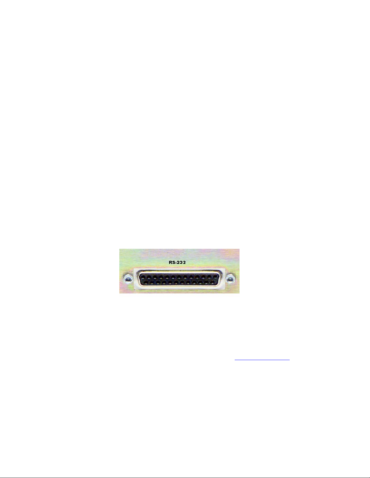
Connectors: RS-232 port, EMI-suppressed DB-25 female connector.
Industry standard EMI suppressed RJ-45 connector for Ethernet.
Remote Interface: Configuration: Eight (8) inputs, RS-232 level-compatible.
Software sensing of both 'go-high' and 'go-low' transitions.
Inputs are protected to +/- 15 VDC.
Connector: EMI suppressed DE-9 male.
Control: User-programmable using built-in Trigger Script feature in
Omnia.Multicast Remote Control software. Virtually any parameter of
Omnia may be programmed to change through this interface feature.
General
Power Requirements: Voltage: 100-250 VAC, 50/60/440 Hz., < 55VA
Connector: EMI suppressed IEC male. Detachable 3-wire power cords supplied
for US and European use.
Internal Power Supply: Overvoltage and short circuit protected. Meets EN55022, EN55011
Level B Conducted Emissions. EN61000-4-2, -3, -4, -5, -6 level 3
immunity compliant. Full international safety approval. CE marked.
Environmental: Operating Temperature: 32 to 122 degrees F / 0 degrees to 50 degrees C
for all operating voltage ranges.
Humidity: 0-95% RH, non-condensing.
Dimensions: 19” wide x 3.5” high x 16.25” deep (48.3cm wide x 8.9 cm high x
41.3 cm deep) including connectors. Unit requires two EIA rack
spaces for proper mounting.
Shipping Weight: 26 lbs. / 11.8 kg
Telos/Omnia Research and Development is constantly working to improve the quality of our products.
Actual specifications are subject to change or improvement without notice.
8
Page 9

Table of Contents
HAZARD / WARNING LABELS 4
Manual Update Notification 6
SPECIFICATIONS 7
Quick-Start Setup Guide 10
Chapter 1: Installation 13
Pre-Installation Tasks.............................13
Installation & Connections ....................15
Powering Up ..........................................18
Chapter 2: The User Interface 19
Using the Jog Wheel ..............................19
Main Menu Orientation..........................20
User Interface Tutorial...........................20
User Interface Concepts.........................22
Bargraph Display Metering Screens ......23
Menu Descriptions.................................24
Chapter 3: Processing Overview 29
Omnia.Multicast and Audio Processing 29
Chapter 4: Omnia.Multicast 31
Omnia.Multicast Connections................31
Processing Worksheet 34
Chapter 5: Editing Presets 34
Preset Editing Overview ........................34
The Processing Display..........................35
Parameter Editing...................................36
Saving, Renaming and Deleting Presets 39
Getting The Sound You Want................40
Chapter 6: Remote Control 44
Software Installation ..............................44
Setting Up and Configuring Omnia
Remote Control
Using the Remote Control .....................51
Using a Terminal Program and Direct
Connection
Trigger Interface and Script Editor........53
Chapter 7: Troubleshooting 60
Omnia Messages ....................................61
Diagnostic and Error Messages 64
Electrical and mechanical safety note! ..63
Narrowing down problems ....................64
Obtaining Service...................................65
WARRANTY 66
.............................................52
......................................45
9
Page 10

.
.Multicast
x3
Sensus Technology: Audio Processing
Overview
Digital audio processing, thus far, has been a numeric replication of tried-n-true analog methods. Sure, progress
was achieved as DSP made it possible to accomplish better algorithms that were either too difficult or expensive
in analog. Still, digital audio processors have not yet migrated from the same conceptual dimension that
dynamics processing has known…until now!
Sensus technology takes dynamics processing into a new realm. Instead of two-dimensional static architecture
and functionality, Sensus adds a third domain where it modifies processing algorithms, architecture, and
functions based upon conditions that are understood by the system. Simply stated, Sensus has the ability to
sense what must be done to a signal, and then “rearrange the furniture” to accomplish its goal. There are
numerous derivatives to this innovative tech, and it can be scaled to many different applications. Following is a
discussion of how this method is applied to a processor used in a coded audio environment.
Codec Provisioning
The codec is now a way of life in the world of audio and broadcasting. Digital broadcasting (HDTV, HD-
R
, DAB, DRM), podcasting, webcasting, cellcasting, and downloadable music files all employ some form
Radio
of codec. This presents a huge challenge to an audio processor. Traditional dynamics processors are designed to
fulfill the requirements of a medium where the functions are static, such as precision peak control and
bandwidth limiting for broadcasting, or the normalization needed for recording and mastering. Each of these
functions is a known static entity. They are singular, one-dimensional functions where the target is known and
the audio processor is designed to accommodate this.
The audio codec, on the other hand, is a moving target. No two codecs are alike, or sound the same. They vary
in sonic quality based upon bitrate…AND…more importantly they vary within the same architecture based
upon audio content! Here is where conventional audio processors fall short when used in a coding environment
and the Sensus tech comes into play.
Until now, dynamics processing has been able to address some of the hurdles and artifacts generated by audio
coding. The codec has the ability to adapt and modify its algorithm internally, in order to provide maximum
throughput, and this alters the sonic artifacts created by the coding process. Unless an audio processor can do
the same, it will hit and miss regarding how well it provisions the audio to avoid artifacts. Sometimes coded
audio sounds acceptable, and sometimes it doesn’t. Conventional processors play games with HF limiters and
static low pass filtering to minimize coding anomalies. In order to condition audio in hopes of artifact
avoidance, the processing will over-compensate audio bandwidth and dynamics. The result is dull, lifeless
sounding audio that still contains audible gremlins.
10
Page 11

Omnia.Multicast
The advent of HD RadioR has introduced the capability to broadcast multiple content streams within the 96kbps
digital channel. To facilitate multicast requires the use of lower bitrate audio coding. The broadcaster can
choose the bitrate for each content channel, as well as the number of desired channels, with a maximum limit of
seven. Therefore it is possible that extremely low bitrate audio channels will exist, and those will require
dynamics processing capable of consistent sound quality that yields low, or no sonic artifacts.
Omnia.Multicast is a processor designed for coded audio, especially low bitrate signals. An innovative codec
provisioning algorithm, using Sensus Technology, yields consistent audio quality that contains little, if any,
coding artifacts. Yet, audio quality does not suffer the dull or muffled quality due to extreme bandwidth
reduction that would normally be employed to mask codec “nasties.”
The Sensus algorithm detects troublesome content for a codec, modifies the processor’s architecture, and then
makes the appropriate changes. These could be dynamics control, bandwidth adjustment, a combination of both,
or the elimination of an unnecessary function. The result is consistent quality through the coded transmission
system, even at low bitrates; i.e. 18kbps – 21kbps. Voice by example, especially without any other
accompaniment, is very difficult to code at low bitrates without the quality and intelligibility suffering.
Omnia.Multicast generates clean, smooth, intelligible, and clear audio that is consistent sounding no matter
what the content is.
11
Page 12
Omnia.Multicast Quick-Start Setup Guide
g
We know that you're probably in a hurry to get on the air with your new Omnia.Multicast. If you have technical
expertise and previous knowledge of audio processor fundamentals, using the following Eight-Point Quick-Start
procedure will get you up and running as quickly as possible. Please refer to the remainder of the Operating
Guide for additional information.
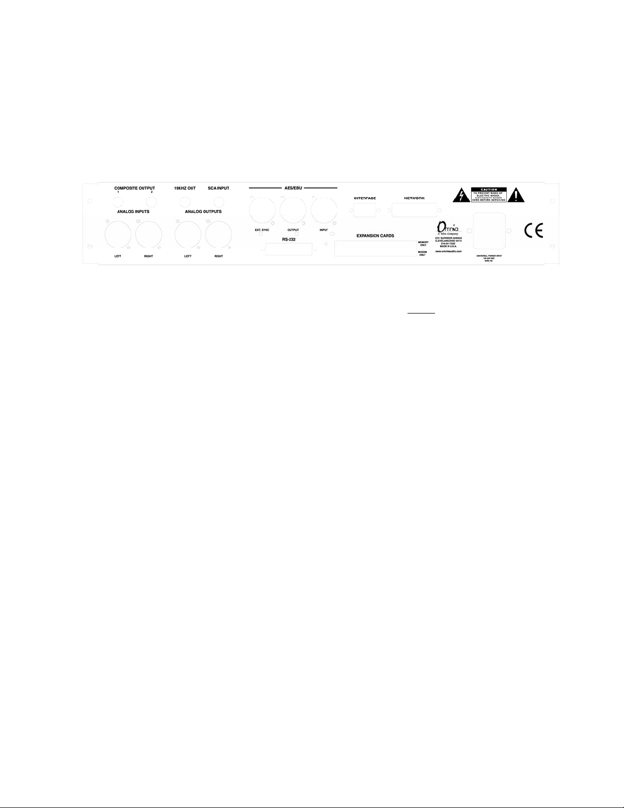
Refer to the following drawing for the location of the various connectors associated with the installation:
Omnia.Multicast Rear Panel View
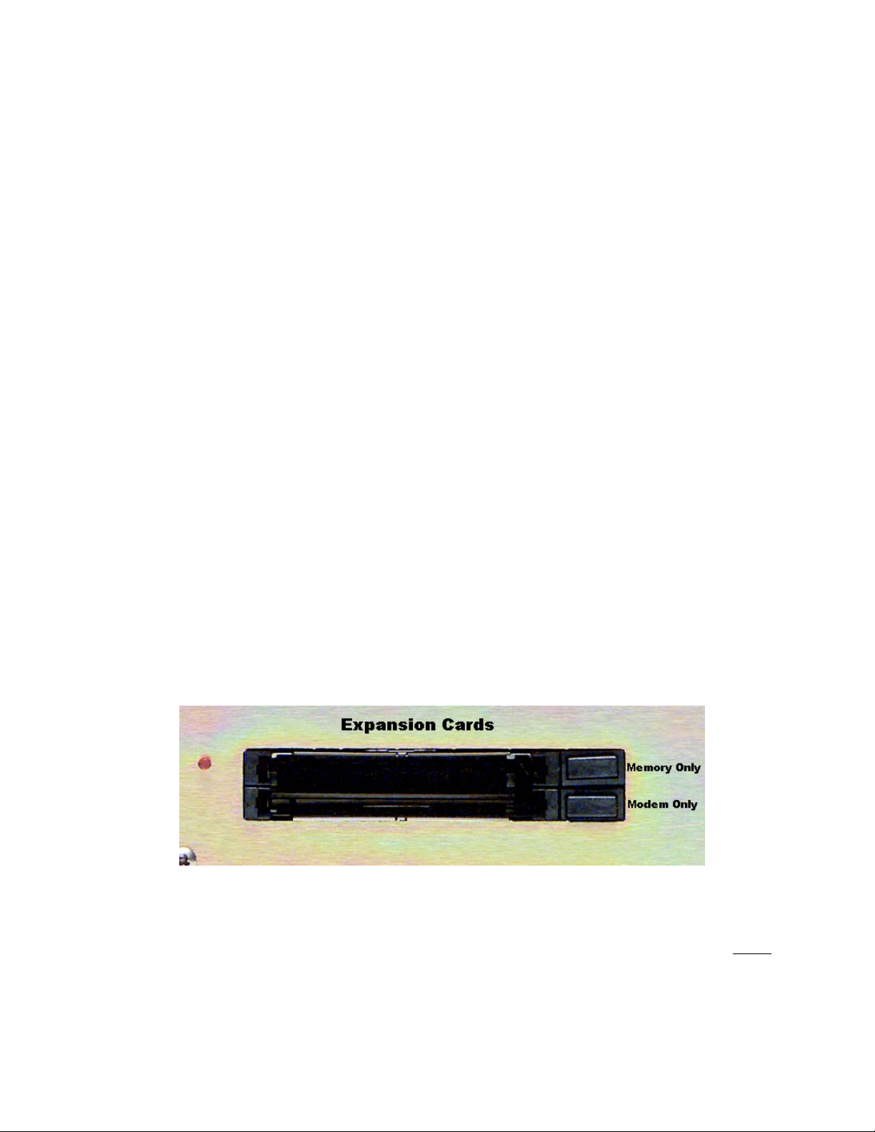
1. Insert the supplied PCMCIA memory card into the top card slot on the rear panel with the large Omnia label
facing up and the version number sticker facing down. DO NOT FORCE!
until the black release button, to the right of the card, pops out about ½” [12.70 mm]. This indicates that the
card is properly inserted in the PCMCIA slot.
2. Install the Omnia.Multicast in the equipment rack using at least two rack screws. If only two screws are
used, they MUST be in the bottom holes of the rack ears!
3. Connect AC power to the unit, and turn on power using the rear-panel power switch.
4. Connect the audio inputs that are appropriate for your installation and provide normal program audio to the
Omnia.Multicast.
5. Navigate to the Input & Output menu by rotating the jog-wheel until Input & Output is highlighted and
then “click” (push in on the jog-wheel) to enter that menu. Navigate to Input Source, click, and select either
the Analog or AES/EBU input. Press the front panel push-button once to switch to the metering screen. If your
audio source is providing an audio feed you should see meter activity on the I/O and Process meters. Rotating
the jog-wheel switches between the I/O and Process bargraph screens. Turn it left for the I/O meters and right
for the Processing gain-reduction bargraphs.
6. Turn the Jog-Wheel to the left to display the I/O metering screen. Observe the input meters (L In and R In)
and adjust the controls in the Input Levels menu until the input meters are peaking up to about -15dB (or a little
higher) with normal program audio. Each press of the front panel push-button will switch between the selected
metering screen and the menu screen where the input level controls are.
7. Connect the audio outputs that are appropriate for your installation. For use in an HD Radio
“EXT SYNC” connector must be provided with an AES-11 (DARS/”AES black”) reference signal at a 44.1kHz
rate that is synchronous to the HD exciter 10MHz master clock. This may be obtained from the exciter directly,
or from an auxiliary GPS receiver.
NOTE: When a 44.1 kHz di
be present on the External Sync input jack or the output sample rate will be 48 kHz.
8. If you are using the Analog or Digital XLR audio outputs, navigate to the Input & Output Menu and adjust
the controls in the Output Levels menu to the correct peak level for the equipment that follows the
Omnia.Multicast.
You’re now ready to go!
ital output sample rate is needed, an external 44.1 kHz AES/EBU signal must
Gently press the card into the slot
R
system, the
12
Page 13
Chapter 1: Installation
Even though we believe the Omnia.Multicast is the easiest processor to install in its class, please take a few
minutes to read through this chapter before proceeding with the installation.
Pre-Installation Tasks
This section offers common procedures for installing Omnia.Multicast.
Omnia.Multicast Components
By now, you’ve unpacked the shipping carton to at least gain access to this manual. Be sure to inspect the
Omnia.Multicast and shipping carton for any shipping damage, which must be reported to your carrier for any
claims.
The Omnia.Multicast shipping box includes the following components:
• Omnia.Multicast processor (containing the DSP hardware)
• Omnia.Multicast PCMCIA card (holding the DSP software)
• Omnia.Multicast Operating Manual
• Warranty Registration Card (fill it out and fax it or return it)
• IEC Power Cord
PC Card and Optional Modem Installation
Before installing your Omnia.Multicast, or even plugging in the power cord, make sure the Omnia.Multicast PC
Memory Card and optional Modem Card (if ordered) are installed into the correct card slots on the back panel
and are fully seated. Installation or removal of cards must be done with the power off unless directed otherwise.
The PC Memory Card is inserted into the top card slot with the larger Omnia label facing up, and the version
sticker facing down. The optional Modem Card is inserted into the bottom card slot below the Omnia PC Card.
Both the PC Card and the Modem Card are keyed to prevent improper insertion. DO NOT FORCE!
press the cards into the slots until the black release button, to the right of the card, pops out about 1/2" [12.70
mm]. This indicates the card is properly seated in the PCMCIA slot.
Gently
13
Page 14

Important Note 1: The PC Card used in the Omnia.Multicast is not a generic PCMCIA cards that can be
bought in any local computer store. They are cards that are specified by Omnia specifically for this product. If
you need a backup card, please contact Omnia Customer Support to purchase an additional card. Inserting a
card of unknown origin risks damaging the Omnia or the cards, and doing so will void your warranty!
Important Note 2: If you wish to operate the Omnia.Multicast using a PCMCIA type modem, you must use the
optional modem card from Omnia. No other modem cards are approved for use at this time. We cannot assume
correct operation of any other modem card, nor can we provide support for it. Typically any external Hayes
compatible modem may be connected to the rear-panel serial port. See chapter 6 for more details on the Modem
and the Remote Control Software.
Note: The rear panel PCMCIA Memory Card must remain in the top slot unless you are prompted by the
system to remove it. Randomly removing the PC Card without system instruction may cause unpredictable
operation and PC Card data damage.
AC Environment
Since the Omnia.Multicast is microcomputer-based, it requires the same clean AC environment as any computer
system. Even though the unit has internal AC input transient suppression, we recommend that transient
suppressors/voltage regulation or an Uninterruptible Power Supply (UPS) be employed as well. This is
especially recommended when installing the processor at a transmitter site. (As is proper grounding) Heavy
transient demands on power lines, from normal switching to lightning strikes, have been known to wreak havoc
with data in computer systems. This is another reason we ask that you give your AC environment thorough
consideration before plugging in your unit. For more information on surge suppression and proper grounding
techniques, please see the tech-talk paper “The Ins and Outs of Surge Suppression” on the Telos website here:
http://www.telos-systems.com/techtalk/surge.htm
14
Page 15
Installation & Connections
Throughout this section reference is made to “software parameters.” These are part of the User Interface, which
is covered in Chapter 2.
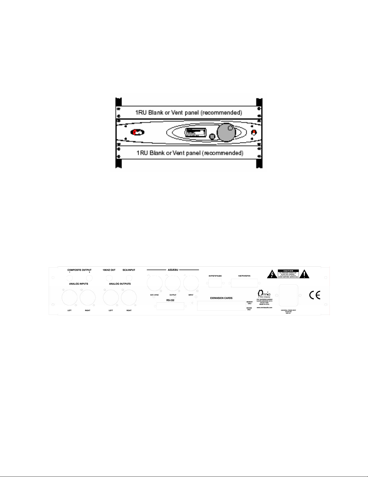
Omnia.Multicast Rack Mounting Requirements
Rack Mounting
The Omnia.Multicast requires 2RU (3.50" [89 mm]) of rack space. Rack mount the unit using four rack screws.
It is preferred to leave at least one rack unit of empty space above the Omnia.Multicast to enhance ventilation
and to prolong component life. Install a 1RU (1.75") vented or solid panel to fill this space. It is recommended
that another 1RU blank panel be installed below the unit for the same reason, if rack space is not at a premium.
Rear Panel Connections
Omnia.Multicast Back Panel Connections
AC Connection (IEC)
The Omnia.Multicast uses a universal power entry module with integral AC switch just above the IEC power
cord receptacle. It can operate on AC mains voltages from 100 to 240 VAC, 50/60 Hz since a self-adjusting
switching power supply is used. In the USA, plug the supplied AC power cord into the unit and then into an
isolated ground AC outlet. Outside of the USA you must obtain an appropriate local IEC power cord.
Audio Inputs (Female XLR)
Balanced XLR-type connectors are used to input both analog and AES-3 digital audio. Even though both analog
and digital cables can be connected, only one input can be set active. Input selection is done through the Input
Source software parameter in the Input & Output menu. The Analog input is the factory default selection.
The stereo analog inputs are designed for standard +4 dBu balanced signals. The digital AES-3 input accepts
any sampling rate between 32kHz and 50kHz. No user adjustment is necessary since a sample rate converter is
built into the unit. Individual channel gain and level setting for both analog and digital is done using the Input
& Output menu’s software parameter settings.
15
Page 16
A Note About Relative Phase: If the relative phase of your installation including the Omnia.Multicast differs
from your existing system, it could cause your announcers to feel they sound “weird” in their headphones. If
this happens, then the relative phase of the processor is 180 degrees from what your talent are used to. To
remedy this, you can reverse the polarity to both of the two analog inputs (is pin 2 or pin 3 hot!?), but it’s a lot
easier to accomplish this function by changing the Input Phase software parameter setting located under Input
Levels in the Input & Output menu.
Discrete Audio Outputs—Analog & Digital (Male XLR)
Individual Left and Right analog outputs are available on two male XLR jacks, as is a single stereo AES-3
output. The digital output is produced directly from the output of the final processing section. The sample rate
automatically synchronizes to any reference rate between 32kHz and 48kHz that is provided on the “EXT
SYNC” input in AES-11 (DARS / “AES black”) format. The sample rate will fall back to an internally
generated 48kHz if external sync is lost. In an HD Radio
R
system, this will make the loss of sync with the
exciter immediately and noticeably audible. The analog output is derived from a D/A converter driven from the
digital output.
Note: Both the analog and digital AES-3 outputs are always active and can be used simultaneously.
Digital Audio EXT Sync Input (Female XLR)
This input accepts an AES-11 (DARS / “AES black”) sample rate reference signal (if an AES-11 signal is not
available, ordinary AES-3 digital audio works as well, however careful layout of digital audio timing signals is
always recommended). The digital audio output will automatically lock to any valid sample rate between
32kHz and 48kHz when it is provided via this connector. If no valid signal is available, the output sample rate
will fall back to an internally generated 48kHz.
RS-232 Connection (DB-25F)
This connector serves two important purposes: It can be used for a local, bi-directional computer connection
with Omnia.Multicast Remote Control, or it can be used for troubleshooting and error code resolution. In the
former case, Omnia.Multicast Remote Control software is utilized. In the latter, any terminal emulation program
can be used. In either case, you must use a standard, straight-through serial cable (not a null modem cable)
between the RS-232 connector and the serial port connector on the computer. Typically, a DB25 male to DB-9
or DB-25 female cable will be used, with the DB-25 male end of the cable attached to the Omnia.Multicast.
The Remote Control application is available as a free download from the
covered in detail in Chapter 6.
www.omniaaudio.com website and is
16
Page 17

Interface Connection (DB-9M)
The 9-pin male Interface connector uses eight pins as “trigger” inputs with the ninth pin as the ground
reference. The trigger inputs can be used to dynamically alter the Omnia.Multicast’s operational attributes in
response to logic signal transitions. The Omnia.Multicast responds uniquely on each trigger input to both go-
high and go-low transitions. With eight inputs, and two possible triggers (logic go-high and go-low), sixteen
unique “trigger scripts” can be written (using the Omnia.Multicast Remote software) to control the
Omnia.Multicast in response to these trigger input logic transitions. The Trigger Script Interface Editor is
covered in detail in Chapter 6.
The Pinout of the Omnia.Multicast rear-panel DB-9 Interface connector is as follows:
PIN 1 activates Trigger Script 1 PIN 6 activates Trigger Script 2
PIN 2 activates Trigger Script 3 PIN 7 activates Trigger Script 4
PIN 3 activates Trigger Script 8 PIN 8 activates Trigger Script 7
PIN 4 activates Trigger Script 6 PIN 9 activates Trigger Script 5
PIN 5 is connected to ground
Ethernet Connection (Optional)
The Remote Control link for your Omnia.Multicast over 10BaseT and 100BaseT networks can be utilized if the
Ethernet Interface hardware option is installed. (Part # 2091-00013) Installation instructions are provided with
the hardware. The setup and operation of the Remote Control software application is covered in detail in
Chapter 6.
17
Page 18

Powering Up
Press the “I” side of the rear panel power switch to turn on the unit. The processor is designed to be turned on
and left on. Press the “O” side of the switch to turn off the unit for servicing.
When the Omnia.Multicast is first turned on, there is a few seconds of delay as the system starts up. An
operating system start up screen is displayed. Under normal conditions it should appear as:
Load Algorithm...
After approximately ten seconds, audio will be present from the analog outputs. The AES/EBU output also
becomes usable at this time. However, full initialization of the software is not complete for several more
seconds. After a few seconds, the Main Menu display will appear:
OMNIA.Multicast
Audio Processing
Input/ Output
Display
Preset: 64kbAACSBR
At this point, the Omnia.Multicast is fully operational. The next chapter covers operation through the front-
panel user interface.
18
Page 19
Chapter 2: The User Interface
A
Now that your Omnia.Multicast is rack-mounted, connected to a program audio source, and turned on, you’re
ready to learn how to operate it! This chapter covers the Graphical User Interface, your window into the
Omnia.Multicast processor.
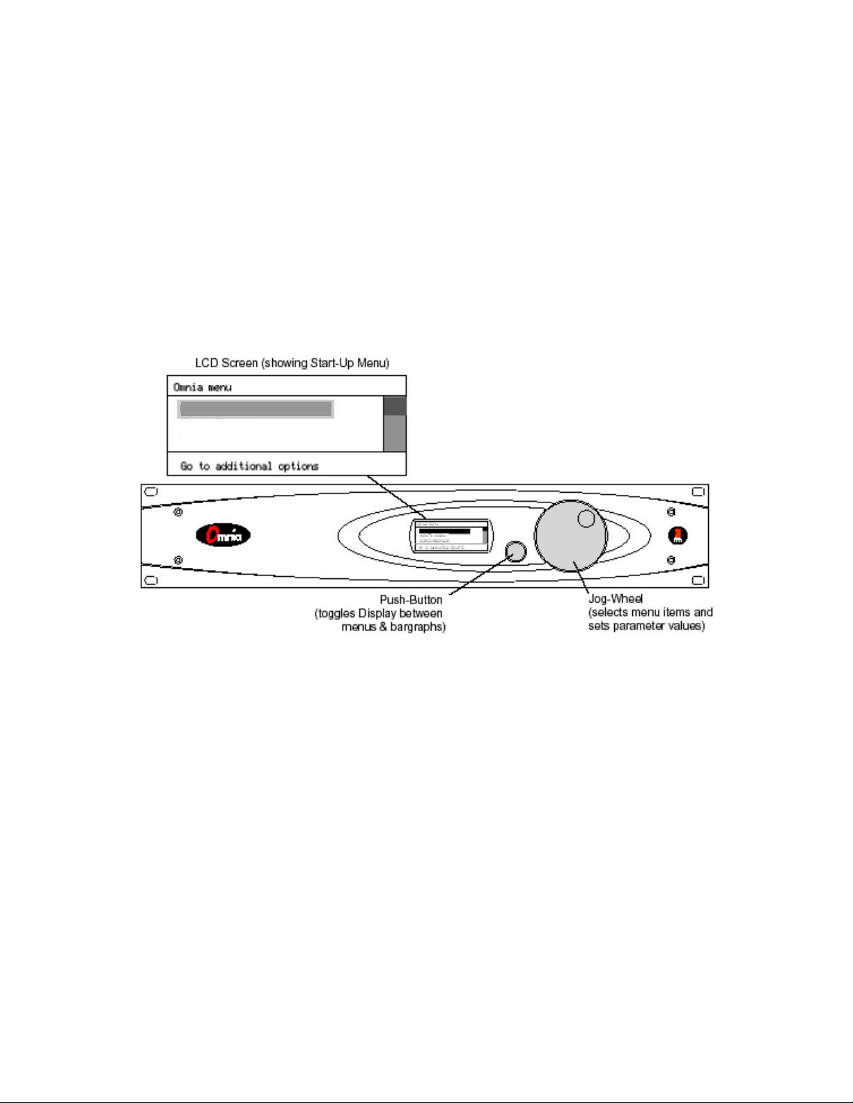
The user interface consists of a front panel-mounted jog-wheel with push-switch, a push-button and an LCD
screen. The LCD screen displays menus, parameter settings and bargraphs (Level Meters and Processing
activity). The push-button toggles between the two display modes: the menus/parameters mode and the
bargraph mode. The menus are used during initial setup and for adjusting the processing parameters. In normal
day-to-day operation, one of the bargraphs is typically displayed to dynamically indicate the real-time signal
processing.
udio Processing
Input/Output
Display
Using the Jog Wheel
The main user control for the Omnia.Multicast is the large, easy to use jog wheel with its integral push-switch.
We believe that you will quickly become comfortable with how it works, and appreciate its simplicity.
Rotating the Jog-Wheel moves a highlighting bar up or down through menus and parameter choices. Pressing
the jog-wheel (called “clicking”) selects the highlighted menu item or parameter choice. When editing the
parameter values, rotating the jog-wheel adjusts the parameter’s value up (by rotating CW) or down (CCW).
Once the desired value is reached, clicking the jog-wheel saves the value and returns the display to the previous
menu or sub-menu.
The behavior of the Omnia.Multicast's menu system is consistent across pages and is easy to learn. The
following procedure is used for all parameter selection and editing:
1. Use the jog-wheel to highlight a menu item or sub-menu item.
2. Click the jog-wheel to open up that item.
3. Once a parameter is displayed, highlight and click the name to open up the parameter value edit box.
4. Use the jog-wheel to adjust the value of the parameter.
5. Click to accept the value and return to the last sub-menu.
19
Page 20

When the front panel is in bargraph mode, the jog-wheel is used to select between various pages of bargraphs
that can be displayed. Push the push-button located to the left of the jog-wheel to change to bargraph mode.
Rotating the jog wheel counter-clockwise moves left one page and rotating clockwise moves right. The pages
do not wrap around from beginning to end or vice-versa. Rotating the wheel CCW will always eventually bring
up the I/O meter page and remain there.
Main Menu Orientation
When the processor is first turned on, several start-up screens are displayed. After ten to fifteen seconds the
Omnia.Multicast Main Menu is displayed with a sliding menu bar along the right side of the screen to indicate
your position within the menu hierarchy. A multipurpose help line is located at the bottom of the display.
Note: After a time-out, the help line will cycle through: the current preset name, and the day and date. The time
is displayed at the right side.
The menu system has been designed to be intuitive and simple to use, with a minimum of sub-menu layers.
Most operating parameters are found less than three sub-menus deep. This allows multiple processing changes
to be made “on-the-fly” with relative ease. The complete system is managed through the four menu choices on
the Main Menu. They are: Audio Processing, Input & Output, Display and Utility
The Audio Processing menu item is shown highlighted in the Main Menu Items illustration. The highlighting is
controlled by the jog-wheel. Rotate the jog-wheel CW to step the highlighting down through the menu items.
When the desired menu item is reached, press the jog-wheel once (“click”) to select that item. If the item has
sub-menus (like Audio Processing), then the sub-menu choices will be displayed. If the menu item is a
parameter selection, then the parameter choices or a bargraph value indicator is displayed. Rotating the jog-
wheel steps through the choices and raises (when rotated CW) or lowers (when rotated CCW) the parameter
value. Click the jog-wheel to select the parameter.
When a sub-menu is displayed, the top menu item will always be the return arrow. Highlight the return arrow
and then “click” to move back to the next higher menu.
OMNIA.Multicast
Audio Processing
Input/ Output
Display
Preset: 64kbAACSBR
User Interface Tutorial
The following two exercises are a useful introduction to the user interface. They also show you how to select an
input source and set input levels, which are among the first things that need to be done to set-up the processor.
Start from the top of the Main Menu (as displayed when the unit is first turned on).
The first exercise demonstrates how to make a parameter selection:
1. Rotate the jog-wheel to highlight Input & Output.
2. Select this menu item by “clicking” the jog-wheel (push once on the jog-wheel). The Input & Output
sub-menu is presented:
Input & Output
Input Levels
Output Levels
Go to additional options
20
Page 21

3. Rotate the jog-wheel CW to scroll down to highlight Input Source.
4. Click the jog-wheel to select Input Source. An expanded edit box appears with the word ANALOG
shown in large type (this is the default input selection).
5. Rotate the jog-wheel to alternate between the available parameter choices, in this case: ANALOG and
AES/EBU. Note that the choices do not “wrap around.” You must rotate the jog-wheel CCW to return
to a previous choice.
6. With ANALOG displayed, click the jog-wheel. The selection takes effect and the screen returns to the
sub-menu item (Input Source).
7. To exit the Input & Output menu and return to the Main Menu rotate the jog-wheel CCW until the
return arrow at the top of the menu is highlighted. Click on the return arrow to return to the Main
Menu.
The next exercise demonstrates how to adjust a parameter that uses a value:
1. From the Input & Output sub-menu, rotate the jog-wheel until Input Levels is highlighted.
2. Click the jog-wheel to select and display the Input Levels sub-menu. There are three menu items
displayed: Input Master, Right Trim and Input Phase.
3. The highlighted item is the Input Master parameter. Click to select.
4. An expanded edit box appears at the bottom of the display with a level bar displayed in the middle:
Edit Input Master setting
-4.0
+6.5
+0.6dB
(was -4.0)
5. Rotate the jog-wheel CW to increase the input gain in 0.1 dB steps. Rotate the jog-wheel CCW to
decrease the input gain. The current setting display updates as the jog-wheel is moved. Just below the
current setting is the previous setting display. “(was -4.0)” All parameters display the previous setting
below the current setting as soon as the jog-wheel is rotated. This allows the parameter to be easily
returned to its previous setting.
Note: The Input Master
control adjusts both the left and right channel levels simultaneously. If needed,
the relative level between the channels can be adjusted using the Right Trim control, which has a range of
–3 dB to +3 dB.
6. Adjust the input settings so that, with normal program audio, the L In and R In bargraphs in the I/O
metering screen (viewed by pressing the push-button and turning the jog-wheel to the left) show peak
indications hitting a bit higher than -15 dB (half to two-thirds of the way up).
21
Page 22

7. Once the desired gain is reached, click the jog-wheel to accept the value and to return to the sub-menu
item. The push-button will conveniently enable you to switch between the parameter adjustment and
the bargraph metering screens.
All of the Omnia.Multicast’s software parameters are set in similar fashion through scrolling through menus and
sub-menus to select which parameter to edit. The parameter choices or values are then selected by rotating the
jog-wheel until the desired setting is displayed. Clicking the jog-wheel selects the parameter value and returns
to the menu or sub-menu item.
Note: Changing the parameter value affects the audio output in real time so that the changes can be auditioned
immediately.
User Interface Concepts
This section introduces you to several important concepts needed to understand and use the Omnia.Multicast.
Presets
The processor comes with presets designed for codec transmissions or netcasting applications. A preset contains
the saved values for every parameter listed under the Audio Processing menu. When a preset is loaded, these
values configure the Omnia.Multicast’s processing.
The factory presets can be used as-is by loading them using Select Preset, or they can be used as a starting point
to tailor the processing for a specific requirement. Any of the presets parameters can be edited (using Edit
Parameters) to obtain the desired sound. The edited preset can then be saved to the PC Card as a User Preset
(using Save to Card as) and selected just like the factory presets. Editing presets is covered in detail in Chapter
5, Editing Presets
Presets can be backed up to your computer using the free Remote Control software available for download at
www.omniaaudio.com. Full information about Remote Control is covered in Chapter 6.
System Parameters
System Parameters are any parameters that are not part of a processing preset. These include all settings in the
Input & Output menus as well as other system settings such as Trigger Scripts. Such parameters are typically
set once and left alone, and having them change when a new preset is selected would be undesirable. These are
stored in a battery-backed NVRAM chip on the motherboard. If an event should occur that clears the NVRAM
(such as a power outage combined with a dead battery etc.), the unit restarts using the last saved set of System
Parameters stored on the PC card. This means all Input & Output settings are restored from the PC card, as well
as other system settings such as Trigger Scripts. Also, the preset that was running when the system was saved to
the card is stored there as the default preset.
Important Note: You should save the System Parameters to the PC card after changing any System
Parameter or if you change your default processing preset.
If your current System Parameters were never backed up by saving them to the PC Card, the parameters
restored would be the factory defaults and the default preset would be the first factory preset in the preset list.
To save the System Parameters, navigate to the Utility Menu and click on System Attributes and then Save to
Card.
Also in the System Attributes menu are the options to Load Defaults (loads the factory defaults) and Load from
Card (loads previously saved parameters or those from another PC card).
22
Page 23

Security
The Omnia.Multicast includes two security levels that permit “lockout” of the unit to prevent unauthorized
personnel from making adjustments. Normal mode allows read-only access to the Omnia.Multicast and its
menu structures. An Engineer mode allows full access to all controls. Additionally, the unit can be locked
altogether, preventing any access whatsoever. Default passwords supplied with the unit are “vito” (all lower
case) for Normal mode and “tomtom” (all lower case) for Engineer mode.
Trigger Scripts
The Omnia.Multicast Remote Control software (available as a free download from www.omniaaudio.com)
contains a special script editor that allows the programming of System Parameter changes that can be
“triggered” by logic state changes on the rear-panel DB-9 “Interface” connector.
Using Trigger Scripts, you can make the Omnia.Multicast do things with contact closures that would normally
need to be done either by manual intervention at the front panel, or via Omnia.Multicast remote control. There
are 8 Trigger Inputs available, and they respond to dry contact closures on the rear-panel “Interface” connector.
Full information about Trigger Scripts is covered in Chapter 6, Remote Control.
Bargraph Display Metering Screens
The bargraph screens are displayed by pressing the front panel push-button (located between the LCD and the
jog-wheel). This toggles between the two display modes: the menus/parameter mode and the bargraph meter
mode. Multiple screens are available in bargraph mode, and are selected by turning the jog wheel. The first
screen can be reach by turning the wheel counter-clockwise until the screen no longer changes. Each screen is
titled in the lower right-hand corner as a navigation aid. The first I/O screen shows the input and output levels.
The second is a combined “Process” bargraph screen that shows the wideband AGC bargraph and three limiter
bargraphs.
I/O Levels Display
Both input and output levels are displayed in real time. The output bargraphs indicate the output levels of the
digital and analog XLR outputs. The bargraphs indicate peak levels below 0 dBFS, which is the absolute
maximum level of the internal digital signal processing. In normal operation with normal program audio, signal
level peaks should regularly indicate just above -15 dBFS and never hit 0 dBFS.
Process Display
The process bargraphs indicate the amount of processing (gain-reduction) of the AGC and Limiter bands in the
Omnia.Multicast. Maximum indicated gain-reduction is 25 dB, which occurs at the bottom of the screen. The
23
Page 24

bargraphs also have a GATED indication as determined by the Gate Thresh or Hold Thresh setting for that
band.
Note: It is normal for the wideband AGC to “recover” to a platform of 10 dB of gain reduction if it is gated
over a long period of time. Refer to Chapter 5, Editing Presets for more information on interpreting and using
the Processing bargraph display.
Menu Descriptions
This section gives an overview of the menus, sub-menus and parameters. The next chapter (Chapter 3,
Processing Overview) presents an overview of the Omnia.Multicast processing. Chapter 5, Editing Presets,
gives more information on editing parameters including procedures for editing the factory presets to create your
own custom presets.
Main Menu
This menu has four items: Audio Processing, Input & Output, Display and Utility.
Audio Processing
It is from the Audio Processing sub-menu items—Select Preset and Edit Parameters, that the unit’s processing
power is unleashed. Omnia.Multicast is equipped with numerous presets that can be selected to instantly
configure the processing. The presets are selected using Select Preset. Selecting Edit Parameters opens up the
parameter-editing sub-menu, which allows any processing parameter to be “fine-tuned” to tailor your
processing. Save to Card as allows the edited preset to be saved to the PC Card as a new User Preset.
Input & Output
This sub-menu provides the Input Levels and Output Levels adjustments for the discrete left and right inputs
and outputs, selection of Input Source (Analog or AES-3), and Mono Mode options. These are generally “set
once” selections or parameters, adjusted during installation and then generally left alone.
Display
This sub-menu has the adjustments for the LCD screen (Contrast and Backlight).
Utility
Numerous maintenance and utility functions are nested within this sub-menu. You can find the currently
running system software versions in the About sub-menu. The housekeeping of Preset and System Attributes
data, along with PC Card Maintenance is provided here. Enabling Security features to prevent tampering by
unauthorized personnel are also provided under this sub-menu. Finally, the Date, Time and the RS-232 serial
Ctrl Port Baud rate can be set here.
Audio Processing
This sub-menu is used to make changes that affect the on-air sound. It has five items: Select Preset, Edit
Parameters, Undo Edit, Save to Card, Save to Card as.
Select Preset
This opens up a selection box to select a factory preset or a user preset that was previously saved to the PC
Card. The name of the preset that is currently running is displayed. Use the jog-wheel to scroll through the list
to find a preset to load. Once the desired preset name is displayed, click the jog-wheel to immediately load that
preset into the unit’s memory. This also returns you to the Select Preset menu item.
Note that once you move the jog-wheel to display another preset name, a message below the preset name
indicates the previous selection, i.e., “(was 32kbWMA)” will be shown if that was the currently running preset.
24
Page 25

This serves as a reminder, so you can reselect that preset in case you change your mind about changing presets,
since there is no way to “cancel” selecting a new preset to load.
A thermometer bar along the left side of the window indicates where you are in the list of presets. All User
Presets are added onto the end of the list, so they will be found when the bar is toward the bottom of the
thermometer.
Editing Parameters
Here you have detailed control of all processing parameters. Such parameters as attack/release times, gate
thresholds, multiband EQ settings and limiting drive are available through a graphical block diagram based
interface. The first blocks name, “AGC Wideband” flashes, indicating that it’s the current parameter. To edit
the AGC Wideband parameters, click the jog-wheel. A list of the parameters relevant to that part of the
processing algorithm is shown (in this case; Phase Rotator, Wideband AGC, etc.). To edit another block’s
parameters, rotate the jog-wheel until the desired block name is flashing and then click the jog-wheel. Detailed
editing is covered in more detail in Chapter 5, Editing Presets.
Undo Edit
Restores the preset state from before the last edit operation.
Save to Card
Saves the current parameters to the PC Card, overwriting any previous settings saved under the current Preset
name. This function cannot be used with factory presets, since they cannot be changed. If you have made
changes to a factory preset and wish to save them, use Save to Card as to save the changes under a new name.
Save to Card As
Opens up a Preset Naming dialog box to allow the Preset name to be changed before saving the preset to the PC
Card. Preset names can be up to 12 characters in length. Click the jog-wheel to select a highlighted character to
be changed. Then rotate the jog-wheel to step through all the possible characters. Once the desired character is
displayed, click the jog-wheel to select that character. The highlighting moves to the next character. To insert a
new character between others, select the character after the insertion point, then change it to the “ins” symbol.
To delete an existing character select it, then change it to the “del” character. When the last character is
reached, rotate the jog-wheel to highlight “Save”. Click to save the preset. Highlight “Cancel” to cancel the
operation.
Input & Output
This sub-menu has five main items: Input Levels, Output Levels, Input Source, Mono Mode, and LPF
Frequency.
Input Levels
Three parameters are located under this sub-menu item: Input Master, Right Trim, and Input Phase.
Input Master & Right Trim: These level controls are active when either Analog input or AES/EBU input is
selected since their adjustments take place in the digital domain. The factory default setting is 0.0, which
corresponds to a nominal average program audio input level of +4 dBu. To change input level, rotate the jogwheel to adjust the level in 0.1 dB steps. The Input Master affects both the left and right inputs simultaneously,
while the Right Trim only affects the right channel over a +/- 3 dB range. Use the level bargraphs to make this
adjustment so that signal peaks read a bit higher than -15 dB with normal program audio. 0 dB corresponds to 0
dBFS (decibels below Full Scale digital, i.e. the digital clip point) so be sure that peaks do not reach 0 dB
regularly or distortion will result.
25
Page 26

It is vital that proper levels are set as they affect the performance of the Sensus algorithm. This is important for
mono content, such as dry, live, voice. A level imbalance will reduce the efficiency of the system to reduce
coding artifacts.
Input Phase: If the relative phase relationship of the Omnia.Multicast is different from your existing system, it
could cause your announcers to think they sound “weird” when monitoring through the system using their
headphones. If this happens, the relative phase of the Omnia.Multicast is 180 degrees different from what your
announcers are used to. To remedy this, you can reverse the polarity with this menu selection. This is the same
as but much more convenient than swapping pins 2 & 3 on both L & R input XLR connectors!
Output Levels
Two parameters are located under this sub-menu item: Output Master and Right Trim.
Adjustment of the left/right audio levels is done in the same manner as setting the input levels. Since these
settings take place before the D/A converter, the settings affect both digital (AES/EBU) and analog XLR
outputs.
Note: Both the analog and digital AES/EBU outputs are active at the same time. Connections can be made
simultaneously to the analog and digital outputs.
Input Source
Selects whether the input is supplied by the Analog or AES/EBU digital input.
Mono Mode
This sub-menu has five items: Stereo, Mono L, Mono R, Mono L+R and Swap.
The Stereo selection indicates that the processor will process a 2-channel stereo signal. Please note that the two
channels cannot be separate un-related signals since the processing is stereo strapped.
Mono L: The signal at the left input is fed to both the left and right channels of the processing.
Mono R: The signal at the Right input is fed to both the left and right channels of the processing.
Mono L+R: A sum of the two input channels is fed to both left and right channels of the processing.
Swap is similar to Stereo but the L & R channels are reversed. (swapped)
Display
Two parameters are set under this sub-menu: Contrast and Backlight.
Contrast adjusts the brightness difference between the lightest and darkest segments in the front panel display.
Note that if this setting is mis-adjusted the display will “disappear.”
Backlight adjusts the LCD’s backlight to compensate for room brightness.
Utility
There are nine parameters or sub-menus reached through this menu item: About, Preset, System Attributes,
Card Maintenance, Security, Set Time, Set Date and Control Port Baud.
About
The first thing displayed when you click on About is the Omnia factory telephone number in Cleveland! To
display the currently running software versions, click OK. The Style and Release version will be displayed.
Click OK again and the Bios, display and Loadset versions are displayed. Clicking OK again brings up the
copyright screen and one more click returns you to the Utility menu.
26
Page 27

Preset
This sub-menu has two parameters: Delete and Rename. Select Delete to permanently delete a User Preset
from the PC Card. A selection box will be displayed allowing you to choose a preset for deletion. Once a
choice is made, a confirmation box is displayed. The preset will not be deleted until “OK” is selected from the
confirmation box. Select Rename to change the name of an existing User Preset. A selection box will be
displayed allowing you to choose a preset to be renamed. Once a choice is made, a naming box is displayed to
enter the new name for the preset. This works as described above in “Audio Processing”: “Save to Card as”.
System Attributes
There are three parameters under this sub-menu item: Load Defaults, Load From Card and Save to Card.
Load Defaults: Reloads all of the factory default system parameters into the system. System parameters are
anything that is not saved with the processing preset, such as input and output levels, and RS-232 baud rate.
User presets saved to the PC card are not affected but the default preset is reset to the first factory preset shown
in the list.
Load From Card: Loads previously saved system parameters from the PC Card.
Save to Card: Saves system parameters to the PC card. This makes a “copy” of the system configuration that
normally resides in the nonvolatile RAM within the Omnia.Multicast, storing it on the PC Card. This simplifies
getting back to a previous state after numerous system adjustments have been made, but you want to return.
Card Maintenance
Erase User Data: Choose this selection when you want to erase all user information on the PC Card, including
user presets, saved system settings, and trigger scripts. When this function is selected, the PC Card is restored to
the initial factory condition, and only the factory presets are available. Before this function is executed, a pop-
up screen will ask for confirmation. Follow the instructions presented on the screen to confirm erasure of the
card.
Security
This menu allows configuration of all Omnia security features, such as password access, screen locking, and
remote access control. There are six sub-menus: Lock Unit, Login, Lock Password, Engineer Password,
Enable Remote and Disable Remote.
Lock Unit: Immediately locks the front panel controls and display. A dialog box is presented for password
entry to unlock the unit. Either the normal mode or engineer mode password can be used to unlock the unit.
Login: Permits access at one of two security levels (Normal or Engineer), using the appropriate password:
Normal mode: vito (all lower case)
Engineer mode: tomtom (all lower case)
Lock Password: Allows changing the password for “Normal” access. This really should be called “Normal
Password”, but our software engineers wanted to include something to keep the users on their toes. This can be
performed either from “Normal” or “Engineer” security levels.
Engineer Password: Allows changing the password for “Engineer” access. Can be performed only from the
“Engineer” security level.
To change a password, use the standard click and turn of the jog-wheel to select the character position you wish
to change, and to select the character for that position.
27
Page 28

After choosing a new password, continue rotating the jog-wheel until OK is highlighted. Push on the jog-wheel.
The password is now saved. If you wish to cancel this operation, just scroll onto the Cancel box and press the
jog-wheel. The operation is canceled.
Caution: Do not attempt to assign the same password to both security levels! You will lock yourself out
permanently!
Enable Remote: Allows remote control access to individual system parameters previously inhibited by the
Disable Remote command (see below). In other words, you can selectively cancel individual parameters that
were disabled for remote access. A list of parameters that have been disabled (through the Disable Remote
menu) for remote users is displayed. When a parameter is selected, it becomes available to “Engineer”
password users to edit through the remote software. Selecting Exit (None on am and net styles) exits the
Enable Remote screen without changing the current settings.
Disable Remote: Allows the user to restrict access to a list of system parameters so that remote users won’t be
able to change the selected parameters. When the Disable Remote option is selected, a list of the system
parameters that are editable through the remote is displayed. When a parameter is selected, it is no longer
editable through the remote command interpreter. Selecting Exit exits the Disable Remote screen without
disabling any parameters. To restore a parameter so that remote users can edit it, use the Enable Remote option.
Set Time
Sets the current time for the unit. The time is set using the familiar “turn and push” action of the jog wheel.
Note: The time can be synchronized to “:00” seconds by pressing the jog wheel in synchronization with the
seconds indicator of an external clock. Note: An additional menu will prompt you to set the unit to Daylight
Saving or Standard time.
Set Date
Sets the current date. The date is set using the familiar “turn and push” action of the jog wheel.
Control Port Baud
This option sets the RS-232 serial communications port baud rate. The default rate is 19200 bps.
28
Page 29

Chapter 3: Processing Overview
This chapter presents an overview of the processor using the block diagram to provide a guide to the various
processing sections.
Note: More detailed technical information about the audio processing employed in Omnia.Multicast can be
found in the Technical Papers section on the Omnia web site (www.omniaaudio.com).
Omnia.Multicast and Audio Processing
There are ten possible processing blocks to be discussed. There is an input AGC function for initial level
control, bass and warmth EQ adjustment sections, a multiband crossover section, a multiband limiter, a mixer
circuit and a final limiter at the output. The following block diagram presents the order of these processing
architecture.
Wideband AGC: A very flexible wideband leveler section to provide transparent and smooth control of the
input program. This is achieved through two significant innovations: a dual referenced gate and an intelligent
“makeup” gain algorithm. The dual gate reference is a unique process that references the input dynamics to a
“rolling” reference level.
A user-adjustable Make-Up Gain feature uses an algorithm incorporating a hidden control signal that knows
when a sustained softer portion of program is occurring. It then “fills in” the softer section so that the average
level is increased. This allows the overall AGC function to operate with a slower time constant, yielding lower
intermodulation distortion without losing loudness in the softer passages.
As an example, with classical music, the orchestra might be playing along at a fairly robust level, then enter into
a quiet passage. A conventional AGC would hold the softer passage down until it was able to slowly recover,
keeping the soft passage much too quiet! With Omnia.Multicast’s makeup gain function, the hidden, faster time
constant will allow a quick recovery, but only during the softer passage. As soon as the orchestra starts to play
louder, the “makeup” time constant yields control to the primary AGC circuit, hence returning gain to the
previous platform level. This sophistication better preserves the dynamic integrity of the signal.
Typically the wideband AGC should be adjusted to give 10-12 dB of gain reduction on moderately loud
passages.
A built-in phase rotator ensures symmetrical processinging of positive and negative peaks. But, for a more
musically transparent sound (or if phase rotation is built-in to your mic processing) this feature can be defeated.
A third-order (18dB/Octave) high pass filter with five selectable cutoff frequencies from 60 Hz down to 20 Hz
allows removal of subsonic frequencies that may cause problems in processing and further along the
transmission path.
29
Page 30

Bass EQ: For those who demand thunderous bass, the Omnia.Multicast’s got it! Up to 12 dB of “thunder” can
be added to shake your listener’s walls! This is not some simple bass EQ, but rather a sophisticated concept that
takes into consideration the time alignment of the low frequencies as they pass through the entire system. This
allows loud, clean low end, with no sacrifice to the overall loudness of your signal. The Deep Bass and Phat
Bass parameters are found under the Bass menu. Deep Bass is a shelf boost at 90 Hz that utilizes a phase linear
12 dB/octave slope to produce the shelving EQ function. Phat Bass is a unique enhancement that adds filtered
harmonics to the bass frequencies. Low frequency texture is emphasized with this parameter. Older materials
sound fuller (or phatter) with the added illusion of loudness.
Warmth EQ: The Warm Bass parameter is found under the Warmth menu. Warm Bass is a shelf boost that
functions up to 150 Hz. Adjusting Warm Bass compensates for program material that is naturally lacking in
upper-bass punch. The parameter is adjustable over a 6 dB range.
Phase Linear, Time Aligned Crossover: Most multiband audio processors must make a compromise in the
crossover area: provide true phase linearity, or dynamic flat response. The problem with implementing only the
former is that, under dynamically controlled conditions, peaks or notches will occur at the crossover frequencies
once the bands are recombined. In an effort to minimize this problem in older designs, crossover frequencies
were phase-offset, so when they were recombined, these peaks and notches would be minimal—thus
maintaining some degree of flatness. Such a compromise results in the loss of phase linearity, which reduces
clarity. In Omnia.Multicast’s DSP implementation, the crossover network is carefully time-aligned so the
recombined spectrum remains flat, regardless of the amount of gain control being applied within any band. This
yields a phase linear response, so that no harmonic content is ever displaced in time. The result: a truer, more
natural sound without smearing.
Multiband Dynamic Peak Limiter: These are not just simple limiter sections using single time constants, but
rather a process that can make adjustments based upon the “peak weight” of the signal. The sophisticated
algorithm relies upon a peak-weighted calculation to determine the strength of a transient peak. It then
determines if very fast dynamic control is required. In this fashion, faster timing is used only when necessary,
and then only under certain conditions that are dictated by the density of the peak signal. If the peak is very
short in nature, then the limiter will ignore it and let it pass onto the next processing stage (the final limiter). A
built-in Hold feature allows the limiter to rest momentarily in order to reduce IM distortion.
Non-Aliasing, Intermodulation Controlled Look-Ahead Limiter: A unique algorithm that provides absolute
peak control to enable maximum system headroom. This contains an embedded intermodulation control method
that removes the artifacts commonly associated with look-ahead limiting, yet producing a clean, intelligible
signal. The Sensus function is also built into this block.
30
Page 31

Chapter 4: Omnia.Multicast
This chapter presents important installation and operation information for Omnia.Multicast. A block diagram is
shown below. A Parameters Worksheet is included at the end of this chapter. Use it as a master sheet for
photocopying so that the parameter settings for any custom presets can be recorded. Presets can also be saved to
your computer and printed using the Remote Control software.
Processor Location
Believe or not, this is an important consideration! Where you choose to locate the processor can have a
profound impact on the overall performance. It is recommended to locate the processor close to the encoder.
There should not be any other signal devices inserted between Omnia.Multicast and the encoder.
Omnia.Multicastnet Connections
The Omnia.Multicast is designed to provide audio processing for Multicasting, HD Radio, DAB and similar
applications. The unit provides full maximum 20 kHz bandwidth and audio processes which are optimized for a
variety of coding algorithms. Because of our extensive experience with MP3 and other codec technologies, the
Omnia.Multicast is designed to maximize the sound quality, even at low bit-rate settings.
When the unit is connected to a professional-grade real-time encoder, the AES/EBU outputs will generally be
used to eliminate conversion steps. Some encoders require the sample rate of input signals fed to them to be
synchronous to their internal rate (or another “master” rate). Examples of such equipment include HD Radio
exciters and importers, as well as many computer audio cards. When connecting the Omnia’s digital output in
such a circumstance, the External Sync connector provides a means to synchronous the Omnias output rate to
the required sample rate. Connect an AES/EBU signal running at the required sample rate to this input, and the
output will automatically synchronize to it (provided it is between 32kHz and 48kHz).
The analog outputs can also be used to connect to the encoding equipment. If the encoder is a PC card, care
should be exercised to prevent ground loops and other connection problems. In the case where the PC card
audio inputs are unbalanced (typically an RCA or mini-phone jack is used), connect the + signal output (pin 2
on the XLR connector) to the tip of the unbalanced plug. Connect the shield on the unbalanced plug to pin 1
(Ground) on the XLR connector. In this application you do not connect pin 3 of the XLR (the - output).
The inputs can be from either analog or digital (AES/EBU) sources, as required. The active input source is
software selectable (c.f. Input & Output menu).
The factory processing presets have been optimized for use with coded audio. They should be used as a starting
point to optimize the audio for your exact coding requirements. For more information on audio processing for
the Internet, refer to the white paper on Audio Processing for Digital Radio and the Internet found on the Omnia
web page:
http://www.omniaaudio.com/
Adjustments to the processing preset parameters are covered in Chapter 5, Editing Presets.
31
Page 32

Processing Presets
Numerous processing presets have been provided as starting points for customizing the sound of your
transmission. Note that we do not warrant in any way that these presets are the de facto standards for the codec
names used. Each was derived in an effort to create a generic starting point for each respective codec.
With all of that having been said, please rely on the presets to get yourself going. From there, we can provide
assistance, if you desire, or you can venture off to discover new frontiers of processed sound. It is our belief that
there is not any nirvana of processed sound, or special secret preset that we keep for our friends. Each situation
in each market is unique unto itself. Try to remember that when “crafting” that special sonic personality for
your installation. Omnia.Multicast gives you the power to create a sound totally different from, and better than,
your competitors. Enjoy that power!
We could publish list after list, but chances are that we will continue to develop new or modify existing presets.
So, a list that is guaranteed to be obsolete would be of little help. Besides, the name of each should be self-
explanatory. If you need more clarification, fell free to contact our technical support department.
Adjustments to the processing preset parameters are covered in Chapter 5, Editing Presets.
32
Page 33

Omnia.Multicast Parameter Worksheet
Preset Name__________________
Engineer
Parameter Value Parameter Value Parameter Value
WB-AGC
HP Filter Lim Thresh
Ø Rotator In/Out Attack
AGC In/Out Release
AGC Drive Hold Thresh Input Master
Attack Right Trim
Release
Make-Up Gain Lim Thresh Input Source
Gate Threshold Attack Mono Mode
Enhancers
Deep Bass
Phat Bass Lim Thresh Output Master
Warm Bass Attack Right Trim
X-Over
____________________ Date________________________
LOW Lim System Settings
Input Submenu Settings
Parameter Value
MID Lim
Release
Hold Thresh
HIGH Lim
Release
Hold Thresh
Input Phase
Output Submenu Settings
Parameter Value
Low Drive
Mid Drive
Hi Drive Low Band
Limiters Mixer
Mid Band
High Band
Final Limit
On/Off
Drive
Sensus
LPF Freq
33
Page 34

Chapter 5: Editing Presets
Many users will be amazed at the dramatic sonic improvements Omnia.Multicast delivers right out of the box
using one of the factory presets. Some will want to tailor the presets slightly to create a more “custom” sound. A
few will wish to delve in and really modify the parameter settings to create their own “signature sound.”
If you’re new to audio processing, we recommend proceeding with caution. Your success in getting the most
out of your Omnia.Multicast processor starts with knowing your objectives beforehand. We firmly believe that
Omnia will get you closer to your ideal than any other processor or combination of processors.
Preset Editing Overview
Clarify Your Processing Objectives
Whether one is seeking better overall quality, specific spectral improvements, or improving intelligibility, try to
articulate and write down your goals. Are there certain characteristics of the sound of another signal that you
want to emulate or surpass? Are there any you want to avoid? This point is probably the most contentious issue
with regards to adjusting processing. Please give thought—real thought, to how you’d like your signal to sound.
What do we mean by that? Well, if your desire is to add fullness, and in most cases it probably will be, decide
on the degree of fullness that you want. This will impact how you set up the processing.
Engineering, programming, and management should all participate in the development of these objectives. After
all, processing can have a direct effect on the bottom line of your station. A little bit of agreement before
installation can save you a whole lot of disagreement afterwards.
Set Aside Some Time
It can take some time, a good deal of serious time to optimize audio processing. We realize that in our business
today, time is a precious commodity. But please don’t try to install the Omnia.Multicast in between other major
projects or the week your boss or your assistant is on vacation. Make certain in advance that the staff members
who helped you set your objectives will be available to consult with you when you adjust the processing
parameters.
How much is enough time? We feel that working with a system for at least a week is a good starting point. We
don’t suggest that you drop everything for a solid week. What we do recommend is that you install the
Omnia.Multicast during a week when you can spend a few hours per day on the project.
The Adjustment Procedure
1. Review your objectives.
2. Once installed, proceed from a degree of processing similar to that currently used by your station and then, if
desired, become more aggressive. A careful approach is less likely to draw hasty, or negative, opinions.
3. Listen for a while, and then adjust. Try to avoid the temptation to “fiddle” with adjustments moments after
getting the system on the air. Remember, you should evaluate the operation over time, not moment to moment!
When it is time to adjust, the provided Worksheet can assist in establishing improved settings of operation.
4. In making changes to the system, do not make hasty or radical changes. Also, do not make too many different
adjustments all at once. If too many parameters are changed at one time, it is hard to determine which change
made the difference. That can be frustrating whether the change made your sound better or worse. Take your
34
Page 35

time with the Omnia.Multicast. You have a great deal of processing power at your fingertips. In order for you to
become “sonically” comfortable, you should learn the limits of each function. Try making changes in different
operating levels. We suggest making changes in increments of no more than +0.5 dB or - 1 dB, or in 1 or 2 step
increments. Try turning different functions on and off. Working this way, you will be able to get a better feel for
what the Omnia.Multicast is capable of producing.
5. Use the “sleep on it method:” Spend time adjusting and then listening, and when the system gets to a point
where it sounds good, stop for the day. In making changes, there does come a time when the ears become less
and less sensitive to adjustments performed. The ears sort of “burn out.” That is why spreading the adjustment
period over a number of days is recommended. If it still sounds good after you have “slept on it,” quit adjusting.
If it does not, continue with small iterations until you’re satisfied. If the procedure is working, you will find that
each day the discrepancies become smaller and you’re making fewer adjustments.
6. When you get it where you like it, stop and enjoy!
The Processing Display
In addition to the menus, the LCD screen also provides processing information in the form of bargraphs
indicating processing activity. The processing display is activated by pressing the push-button located to the
lower right of the LCD screen. From any menuing screen, pressing the push-button will switch the LCD screen
to the Processing or Levels bargraph display.
Display Contents
The processing bargraphs provide a wealth of information about the dynamics control in Omnia.Multicast.
Each displays the amount of gain reduction, with the top of the bar indicating no gain reduction, and the bottom
indicating 25 dB. Thus, the bar “fills-in” from the top down to emulate an analog gain reduction meter.
The AGC algorithm responds slowly to the program dynamics, and this is reflected in the meters. They will
change gradually in real-time to indicate processing activity. Additionally, the appearance of “Gated” next to a
meter indicates that the gate has activated in the AGC. In this state the meter will freeze or return to a platform
level, depending on the settings of the particular AGC.
The limiter algorithms have the ability to modify the style of peak control that is employed on a moment by
moment basis. This can be seen if observed over a period of time, say a few minutes. During normal operation,
the limiter indicators will have a dynamic “bounce” that you will be able to get a feel for. But every now and
then, the limiter will very quickly show a large amount of gain reduction. Notice that the response can be very
fast at times.
Another feature, indicated by the appearance of “Gated” next to each band, is the limiter “Hold” function.
During brief pauses in limiter activity, the bargraphs “freeze” to show the limiter has entered the Hold function
of the algorithm; akin to the Gate function in the AGCs. This is most easily noticed when there is a “dry” voice
being processed. The Limiter bargraphs, like the AGC section, can indicate up to 25 dB of linear gain reduction.
Interpreting Processing Displays
Through observation of the processing bargraphs, significant information can be acquired and analyzed about
the audio signal on a moment-by-moment basis.
Since Omnia.Multicast is capable of performing many different processing functions at different times, the
display bargraphs may indicate various kinds of operation. This is based upon dynamic range differences in the
program material. For program material that is already processed or lacking dynamic range, this will cause the
35
Page 36

bargraphs to indicate differently than material that possesses a high degree of dynamic range. This is because
audio signals that lack dynamic range, naturally or by previous processing, will possess a high level of RMS
energy and a low level of peak energy. Conversely, audio signals with wide dynamic range possess lower levels
of RMS energy but higher levels of peak energy.
Program material that has low dynamic range, high RMS and low peak levels will generate more activity in the
AGC sections and less activity in the Limiter sections in the displays. This is due to the AGC section
responding to the RMS energy while the Limiter section reacts to peak energy. When these situations occur, it is
normal for the unit to indicate more AGC action as compared to Limiter action. Sometimes the Limiter section
may not indicate any action! Examples might include heavily processed commercials or music, or music with
passages of sustained level. A good example is the Aerosmith CD “Pump.” This recording has very little
dynamic range. Try any up-tempo selection from this disk and you will see the Wideband-AGC section make
initial adjustments along with small amounts of limiting. Once adjusted, the Wideband-AGC section will be
deep in gain reduction, although with little movement, and limiting action will be minimal.
When the programming has wide dynamic range, with low RMS but high peak levels, the opposite will occur.
The Limiter section becomes active, while the AGC section will appear not to respond. During these situations
it is possible that the Limiter sections could approach full scale, while the AGC section may only indicate half
scale. Examples are: vocal passages or live voice, classical music, or passages with transient levels. Good test
examples: almost anything classical, or almost anything by Steely Dan!
Also keep in mind that the AGC section will operate much more slowly than the Limiter sections. This is in part
due to the nature of each function. Remember, the AGC section operates on the RMS energy, which is
calculated over an “integration” time by the signal processor. It is during the integration time that the “average”
level is established, and gain adjustments, if needed, are made. This is why the AGC section will move slower,
since they are making changes, as needed, over relatively long time periods.
With the Limiter sections, the intention is to control the peak activity. This is accomplished by controlling, or
limiting, the highest crest/peak, of the audio waveform. There is intrinsically little time available to get this job
done. The Limiter section must quickly grab the signal, reduce the gain to the proper operating range, and then
return the gain to normal until the next peak signal comes along. Peak energy must be detected and adjusted in a
quick and accurate manner while, at the same time, not interfering with the sonic integrity of the audio signal.
For this reason, the Limiter sections operate very quickly, and on an as-needed basis.
Since these displays are capable of providing a wide range of information, we do not recommend setting up this
system to any specified amount of processing based upon meter indications. Instead, we recommend setting up
the processing by using your ears to judge the sound. We provide the meters to analyze the signals and aid you
on adjusting the specific parameters needed to achieve the desired sonic results.
Parameter Editing
The Omnia.Multicast system architecture has a great number of audio processing functions and features. The
following sections detail the adjustments one can make while in Expert Edit Mode.
Before tackling this section you must be familiar with navigating through the menu system and be comfortable
with the controls. (See Chapter 2, The User Interface) If so, you’re ready to tackle more sophisticated
adjustments. To edit a preset it must first be loaded into Omnia.Multicast. Once loaded, it can be modified to
your heart’s content. The changes can then be temporarily used, or they can be saved to the PC Card so they
won’t be lost.
The Audio Processing / Edit Parameters sub-menu and those below it provide access to the heart of
Omnia.Multicast, where comprehensive and very fine adjustments to the audio processing are possible. We
36
Page 37

suggest that only those with experience in processing adjustment should make use of this section. Here is where
the user can either shine and stand out on the dial, or crash and burn if they’re not careful! That’s right: Unlike
other processors, we don’t artificially limit the range of adjustments to try to keep you out of trouble—you
better know what you’re doing. This section of the manual will help you do just that.
Upon entering this menu, a unique graphical block diagram of the processing system appears. This block
diagram not only indicates the architecture of the processing system, but also provides access to the sub-menus
for each of these parameters. Take a moment and rotate the jog-wheel. The diagram scrolls from left to right as
different processing blocks are selected. Clicking the jog-wheel enters the sub-menu for that processing block.
Parameter adjustment is then accomplished using the previously discussed methods—turning the jog-wheel to
adjust a parameter, then clicking on it to effect the selection. Generally, turning the wheel clockwise will result
in “more” processing. For example, attack and release times become smaller as the wheel is rotated clockwise.
While this may at first seem counter-intuitive, it provides consistency across all the controls. The following
paragraphs will provide insight on each of the parameters.
Notice in the lower right-hand corner of the screen there is a horizontal scroll indicator to show the exact
location within the block diagram. This will help in navigating through the system.
Wideband AGC
There are numerous items to adjust in this selection. Of note are the Attack and Release functions. The lower
numbers relate to slower time constants, and the larger numbers relate to faster time constants. Since the time
constants are program-dependent, absolute time constant values (in ms.) would be useless—therefore the use of
numbers. Use a higher number if you want “fast” attack and release times, and lower numbers for slower attack
and release times. Generally, the best sound quality is achieved with slow attack and release times; greater
loudness is achieved with faster attack and release times.
The other item to note is the Make-Up Gain menu. This parameter sets the amount of gain to be filled in during
quieter, softer program passages. The range is OFF to 7. This function is also program dependent, and it
interacts with the main time constants. As the attack/release times are modified, the system also scales the
Make-Up Gain time constants. Use less makeup gain for processing more faithful to the source material; use
more makeup gain for greater loudness and “density.”
Use the Drive control to ensure you are in adequate gain-reduction. Having the control set too low can rob you
of loudness, and defeat the “leveling” function of the Wideband AGC in dealing with varying program levels.
If wideband leveling is being performed upstream of the Omnia, the Wideband AGC control can be set to
“OUT” to bypass the AGC entirely.
Use the Gate Thresh control to set the level at which gating occurs, hence “freezing” the gain during short
pauses. Correct use will eliminate “pumping” effects that can lend an unnatural quality to the processing.
Additionally, the control for the HP Filter is located in this menu. In most systems, subsonic frequencies in the
input audio program should usually be rolled off to prevent difficulties with certain codecs. The
Omnia.Multicast has a third-order (18dB/Octave) high-pass filter with five selectable cutoff frequencies from
60 Hz down to 20 Hz. The factory default is “Out”, which means that audio frequencies to well below 2Hz are
passed through the system without attenuation. You may select one of the other values that may be more
appropriate for your system.
One final control is the Phase Rotator bypass. Phase Rotators (also known as Phase Scramblers) are commonly
utilized to make asymmetrical waveforms (such as voice) more symmetrical. Phase rotation can make talent
voice sound cleaner, but since it disturbs the phase integrity of musical signals, music might sound more faithful
to the original source if phase rotation is not used. Off can be chosen if previous phase rotation has been
37
Page 38

performed in your system (in a microphone processor for example) or to preserve the phase integrity of the
original program as described above.
Bass & Warmth Enhancement
Deep Bass EQ: For those who demand thunderous bass, the Omnia.Multicast has it! Up to 12 dB of “thunder”
can be added to shake your listener’s walls! This is not a simple bass boost, but a rather sophisticated concept
that takes into consideration the time alignment of the low frequencies as they pass through the entire Omnia
system. It allows a
won't tell you where the control is in the signal chain. But we will tell you that Deep Bass function is a shelf
boost at 90 Hz, utilizing a phase compensated 12dB/octave slope to emulate the EQ function.
Phat Bass EQ: Phat Bass is a unique enhancement that adds filtered harmonics of the lower registers to the
upper bass frequencies. The algorithm extracts information contained in the initial attack to do its work, and low
frequency texture is therefore emphasized. Older recordings sound fuller (or phatter) with the added illusion of
loudness. Phat Bass EQ also helps radios with small speakers sound like they have more bass than they actually
do. A little of this effect goes a long way so be careful not to apply too much boost. Be sure to listen on several
different types of radios to arrive at a setting that works best for all of them.
Warmth EQ: The Warm Bass parameter in the Enhance section of the Process submenu is a shelf boost at 150
Hz. This compensates for program material that is naturally lacking in upper-bass punch. Be judicious about
applying too much, as this can cause excessive gain-reduction in the low and mid bands. Also, the resonant
frequency of most automobile interiors lies in this frequency range!
loud, clean low end, with absolutely no sacrifice to the overall loudness of your signal. We
XOver
The crossover points are set in software and cannot be modified. They are set at 150 Hz and 3 kHz. You can
however, change the output gain of each crossover filter using the LF Drive, MF Drive and HF Drive controls.
These control the drive level of the audio fed to the following respective multiband section. These are some of
the key adjustments you will be using to increase loudness! The greater the drive, the greater the loudness and
the effect of dynamic equalization to achieve a consistent spectral balance. Increasing some bands while not
others effectively adds emphasis to those boosted bands.
Multiband Limiter
The Limiters work faster than the AGC and operate mostly on signal peaks that get through the slower AGC
section. There are three limiter bands. Drive to the limiters is controlled by the Xover block. The Hold Thresh
is similar in function to the Gate Thresh in the AGC. It sets the threshold of where the limiter’s Hold algorithm
begins. When it’s in the OFF position, the limiters will attack and release as you would expect them to. With
Hold Thresh enabled, the limiters will momentarily stop and rest during very short pauses, especially during
live speech. The Limit Thresh control adjust the level at which the limiters begin to operate. Higher dB values
(CCW rotation) will result in less limiting action, and more audio signal getting to the final limiter section.
Mixer
This performs the summation of the multiband sections before the final limiter. Be careful when adjusting this
section, as too much level from any particular band could cause an excessive amount of density to that range of
frequencies. If your desire is to “EQ” the sound, you should perform that using the drive levels in the XOver
menu. This final mixer is mainly for minor “EQ” changes to the overall sound. Adjustment of this section
should be done as a last resort.
38
Page 39

Final Limit/Sensus
This is the final limiter where absolute peak control is accomplished. There are four controls here: With the first
you can turn the final limiter ON or OFF. This should normally be left ON unless the equipment following the
Omnia.Multicast has a non-defeatable limiter or otherwise requires non-limited audio.
The second is the Drive control, which controls the amount of final limiting. The gain-reduction of the final
limiter can be monitored on the Process Bargraph screen. The third menu item is the Sensus function: which
provides a list of options to optimize processing for various low bitrates. The choices are: OFF, 64kbps, 48kbps,
32kbps, 24kbps, 21kbps, and 18kbps. When editing manually, choose the selection that corresponds to the
codec bitate. If the bitrate is above 64kbps, then use the 64kbps mode or set the mode to OFF. If the bitrate is
between two of the choices, then experiment with the bitrates selection that’s above or below the target codec
bitrate.
The final menu item is the low pass filter frequency -- LPF freq. This is a key control for matching the audio
bandwidth of the processed audio to the bitrate of the following codec. Proper bandwidth will ensure minimal
side effects and aliasing distortion products from the codec process. Settings are: 4, 6, 8, 10, 13, 16 and 22 kHz.
These are the frequencies at which the filter reaches full (at least 100dB) attenuation. A frequency at or below
half the sampling frequency of the encoder should be selected.
An important tool that aids a processor with codec provisioning is low pass filtering. Omnia.Multicast offers
adjustable output filters that should be set based upon the codec. The following chart recommends low pass
filter settings that support the AAC-SBR, MP3, and Windows Media (WMA) codec applications:
AAC/SBR Output LPF MP3 Output LPF WMA Output LPF
24kbps 6kHz - 8kHz 24kbps 4kHz 24kbps 5kHz - 6kHz
32kbps 10kHz 32kbps 4kHz-6kHz 32kbps 8kHz
48kbps 13kHz 48kbps 6kHz 48kbps 10kHz
64kbps 16kHz 64kbps 8kHz 64kbps 13kHz
Saving, Renaming and Deleting Presets
Upon completing a preset editing session, the processing changes should be stored. This writes the processing
information to the PC Card through overwriting an existing preset or by creating a new one. It is also possible to
delete presets that are not needed anymore. This frees up memory space for saving newer settings.
Omnia.Multicast has the capacity to store up to 25 User Presets.
Saving Presets
When processing adjustments are completed, a choice should be made to either save the changes over the
existing preset or create a new User Preset. This is done from the Audio Processing menu. If you want to save
the changes using the current preset name, choose the option Save to Card from the menu. When selected, the
system will save the latest changes to the current preset name. A dialog box appears on-screen to verify this.
Note that factory presets cannot be overwritten – use Save to Card as instead.
To save the preset under a new name, thus keeping the original preset and creating a new preset that will be
added to the bottom of the preset list, use the Save to Card as menu choice. When selected, a Preset Naming
dialog box appears on the screen, so the characters in the new User Preset name can be entered.
For a detailed description of how to use these functions, see the “Audio Processing” subsection of the “Menu
Descriptions” section in Chapter 2.
39
Page 40

Renaming A Preset
Renaming presets is not done under the Audio Processing menu, but rather is done under the Utility menu
located off of the Main Menu. To rename a preset, select Utility from the Main Menu. From the sub-menu list,
select Preset, then select Rename. This opens up the Name Preset Dialog Box so that a new name can be
entered. For a detailed description of how to use this function, see the “Audio Processing” subsection of the
“Menu Descriptions” section in Chapter 2.
Deleting A Preset
Using the Preset sub-menus under the Utility menus, as discussed in the previous section, the Delete option can
be accessed. For a detailed description of how to use this function, see the “Audio Processing” subsection of
the “Menu Descriptions” section in Chapter 2.
Getting The Sound You Want
If you believe that you’re in a density war and you need to react, here are some suggestions that should help.
Conversely, if you have the luxury to strive for increased sound quality, we’ve got suggestions for you, too!
Please be advised that there will always be a subjective compromise whenever the desire is to shift to a louder
personality. Omnia.Multicast is designed to minimize the qualitative trade-offs that one needs to make.
We recommend that before starting the process of cranking it up just for the sake of it, try to figure out what
sonic characteristics you feel are needed in order to be more competitive. In many instances it’s not just
increasing the drive to the limiters. It can be as simple as creating an illusion of added loudness by changing a
time constant parameter. There are known situations where the use of stereo enhancement can also create
apparent loudness. Please don’t bite at the first temptation to crank the system. Sometimes the old adage of less
is more really applies!
Before delving into alternative processing possibilities, please give the next brief section some thought. It may
help provide you with direction to your overall plan.
A Word About Density, Clarity, and Intelligibility
Making this confession is a little like telling your parents you dented the car. But here it goes: It’s OK to be
loud. Very loud.
In the past, loudness was a problem due to the limitations of the processors you had available to you. If you
processed more heavily, then you either had to adjust your single processor outside of its “safe” range or use
multiple boxes and risk conflicts among each other.
Omnia.Multicast has changed all of that. It knows how to get a station sounding loud without the artifacts or
grunge created by your current processor when you try to make it loud. And Omnia.Multicast makes loudness
an option for all formats.
One more confession. It’s also OK for your station to not sound loud, yet sound incredibly musical and grunge-
free, because the Omnia.Multicast has given you the choice. Our intention is to provide you with a system that
will maximize the audio quality of your signal, yet at the same time satisfy your competitive requirements.
40
Page 41

Quality Versus Density
The trade-off between quality and loudness is primarily affected by the use of the limiting sections. With
increased use of limiting, intermodulation distortion is increased. The added dynamic activity of the limiters
causes the audio to sound as if it is “tight” or “squashed.” This can be perceived to the ear as “pumping,”
“breathing,” “dense,” or “mushy.”
Please remember that a core objective of Omnia.Multicast is to offer maximum intelligibility, especially at low
bitrates. Thus, processing for heavy density can mask that effort. A codec provisioning processor is more so a
tool as compared to a weapon.
The following sections are provided to assist you in designing the personality of your station’s sound. As said
earlier, there is no precise recipe for setting audio processing. There are a few basics that can get you more
along the line of your desire. In the end, it will require a concerted effort of extended listening and subtle
changes over time to achieve the desired results. And remember the guidelines discussed at the beginning of this
section: know your goals, take your time, and adjust methodically.
Increasing Density/Loudness
Try to resist the temptation to crank on the aggressive processing sections. Those will add loudness, but usually
at the cost of quality or intelligibility. Many times, building a little more RMS level in the AGC sections will do
the trick. The following are some suggestions on where to begin to make changes. Try them in the order
described.
Increasing loudness can be accomplished in four ways:
1. Alter the following parameters in the AGC:
• Increase the Drive to the AGC sections.
• Increase the Release time settings to operate faster.
• Increase the amount of Make-Up Gain.
2. Modify the Multiband Limiter sections:
• Increase the Drive to each section.
• Increase the Release time settings to operate faster.
• Set the Hold threshold to a low value.
3. Drive the Limiter sections harder.
4. A combination of all of the above! Sounds crazy, but it’s true! In this situation, resist the temptation to make
too many changes at once. When that occurs, it becomes difficult to determine why, or why not, an adjustment
made sense. Let one specific area at a time be the main focus. After that area is satisfactory, then move the
focus to another area, as needed.
Based upon the above suggestions and theories, experiment with different styles of processing. Some
broadcasters prefer to have their processing be perceptibly loud, but dynamic. This may not result in the loudest
station on the dial, but it gives the illusion of loudness, yet retains detail and clarity. This can be done by
centering the efforts in the Limiter sections, and avoiding the heavy use of the Final Limiter. A trick to consider
here is to use very fast attack and release times in the multiband limiters, but make sure that they do not produce
more than 5 dB - 7 dB of gain reduction. This keeps the IM distortion of the limiters to a minimum. Here the
Limiter sections are relied upon to generate higher RMS levels, which translates into increases in perceived
loudness.
41
Page 42

If the quest is to appear the “loud and proud”, then the limiters should be leaned upon a bit more. Loudness at
all costs is usually the reason for moving the processing in a direction like this. Using larger amounts of drive to
the multiband limiters, along with faster release times will generate a signal of consistent density. Also, an
increase in final limiting will further aid this. The effect of the processing set in this manner is that the audio is
consistently loud at all times. The drawback is that the density can cause listener fatigue over a prolonged
period of time. While Omnia.Multicast is designed to minimize listener fatigue, it is capable of generating large
amounts of density that could eventually lead to fatigue. Be careful!
Adding More Detail—When Loudness Isn’t The Last Word
Now that we’ve “squished the grape,” lets look at what it takes to undo a heavily processed signal. Basically,
just reversing the procedures listed above will do the trick:
1. Reduce the drive to the Final Limiter.
2. Back off on the influence of the Limiter stages:
• Reduce the amount of Drive.
• Reduce the Release time to slow down recovery.
• Raise the threshold of the Hold function.
3. Ease up on the Wideband-AGC sections:
• Reduce the Drive to the Wideband-AGC.
• Reduce the Release time to operate slower.
• Reduce the amount of Make-Up Gain.
Backing off the limiting sections first will allow the processing to still retain a level of loudness while restoring
quality. Start with reducing the Final Limiter amount in 0.5 dB steps. It’s surprising how much detail can be
restored from just a small change of 0.5 dB. Generally, a change in the Final Limiter amount will have the most
noticeable effect on quality, but it will also affect the relative loudness level, too. You’ll need to find a “happy
medium” that’s right for you.
EQ Changes
Tailoring the shape of the overall audio spectrum can be done in three different sections:
1. The drive settings in the X-Over menu. This sets the drive to the multiband AGC sections.
2. The relative amount of Drive to the multiband limiters.
3. The setting of the final Mixer.
All three options will provide noticeable change in EQ. We suggest you use the first two listed options. In either
case, an EQ change is still followed by a dynamically controlled stage. Therefore any excessive EQ change can
be countered by either the subsequent AGC or Limiter. The last option, the Mixer, is designed to provide a final
minor trim to the spectrum. Since this stage is after all of the dynamic AGC and Limiting, a radical change in
level in the Mixer will result in excessive look-ahead limiting in that respective band. We suggest that any
changes implemented here be limited to about 0.5 dB to 1.0 dB of boost. Naturally, any decrease in level can be
done to any desired amount.
42
Page 43

Thunder Bass
Omnia.Multicast has the power to shake the walls with low end! If your source material has it, Omnia.Multicast
will process it and put it on the air with muscle! Making changes to this characteristic is done using these
parameters, in the order listed:
1. Increase the amount of Bass boost.
2. Increase the drive to LF Lim with the appropriate control in the X-Over stage.
3. Speed up the Release time in the LF Limiter section.
Again, moderation is the key! If all of the above are utilized, then the possibility of causing severe low
frequency buildup can occur. This would then produce the illusion of “lost” presence and high frequencies.
Generally, an increase in the Bass boost function alone will provide a substantial and sufficient enhancement to
the low end.
Upon selection of a preset and low pass filter, audition the entire coded system before making adjustments.
Attention should be given to program content that segues from music to voice and back again. The quality of
vocal content should not alter due to the coding process. If this is noticed, try reducing the Sensus function by
one step and then reevaluate.
Adjusting processing for coded audio is different than conventional radio. While many of the dynamics
functions are the same, i.e. compression, limiting, EQ, etc, please consider that the audio processor as a tool to
improve the performance of the codec. This is especially true at lower bitrates. When making processing
adjustments, try to avoid building too much density in the presence and high frequency ranges. Density in this
spectra cause codec efficiency to become reduced and artifacts increased. Even though Sensus technology is
applied down stream, and it will improve system performance, remember that the processor is a sum of its
collective dynamics parts and the end result is based upon the cumulative effect of its settings.
43
Page 44

Chapter 6: Remote Control
This chapter covers Omnia.Multicast Remote Control version 3.4.0 and greater. The Omnia Remote Control
software is a Windows (Windows 95, 98, NT 4.0, Win2k, WinXP) software program that allows remote access
to the Omnia.Multicast processor adjustment using any PC running the aforementioned versions of Microsoft
Windows
by pointing your web browser to the “Support” page of our web site: (www.omniaaudio.com).
The Remote Control application has a very similar look-and-feel to the Remotes for the Omnia-5 and Omnia-6.
Before it connects to the Omnia, the words “OFF LINE” will be displayed where the Preset Name and System
Time will be displayed once the remote connection is made. All metering activity is also at idle.
©
. The latest version of Omnia.Multicast Remote Control Software is always available free of charge
Omnia.Multicast Remote Control as it appears on your computer screen
Software Installation
Installation is simply a matter of putting a copy of OmniaRemoteXXX.exe into the folder name of your
choosing, and running it from that location. This file is the actual raw executable so there is no “installer” and
no permanent changes are made to your computer system or to your Windows registry.
Using standard Windows procedures, create a new folder by the name you wish to use, and place a copy of
“OmniaRemoteXXX.exe” in that folder. You can then also create a desktop shortcut to that executable if
desired.
When the program is freshly installed but has not yet been run, “OmniaRemoteXXX.exe” is the only file in the
specified folder. However, the first time that the program is run, it will create a small new file called
“connect.dat”, which contains your connection type information. When you first run the Remote Control
program, there is no “connect.dat” file yet, so you will receive the error message “No connection database.
Creating new database”. This is normal and is no cause for concern.
44
Page 45

This message is normal the first time the program is started!
Note: When you install Omnia Remote Control software updates, you should move the old version and its
associated connect.dat file to a new folder. This way, conflicts with different versions of the connect.dat
database will be avoided. If you wish, the old version’s folder can be safely deleted once the update is complete.
You will also want to use unique folder names for each copy of other Omnia remote control programs if you
have those installed. Please note that the remote control programs themselves, as well as their associated
connect.dat files are unique for each version of the Omnia Classic, Omnia.Multicast, Omnia-5EX, Omnia-6EX
and Omnia Toolvox.
Setting Up and Configuring Omnia Remote Control
The Remote Control Program for the Omnia.Multicast is specific to Omnia.Multicast. As stated earlier, Omnia
Remote Control programs designed for our
Omnia.Multicast. The latest versions of all Omnia remote control programs are always available free of charge
through the “Support” page of our web site:
Start the OmniaRemoteXXX.exe program. As mentioned earlier, when the program is run for the first time,
you will get an error message saying: “No connection database, creating new database.” This is normal.
Checking the Version Number of your Omnia.Multicast Remote Control Program
You can check the version of your Omnia Remote control program by clicking on the “About” option under the
“Help” menu option.
other Omnia family of products will not work with
www.omniaaudio.com
The Omnia.Multicast
Remote Control version
number is shown here.
45
Page 46
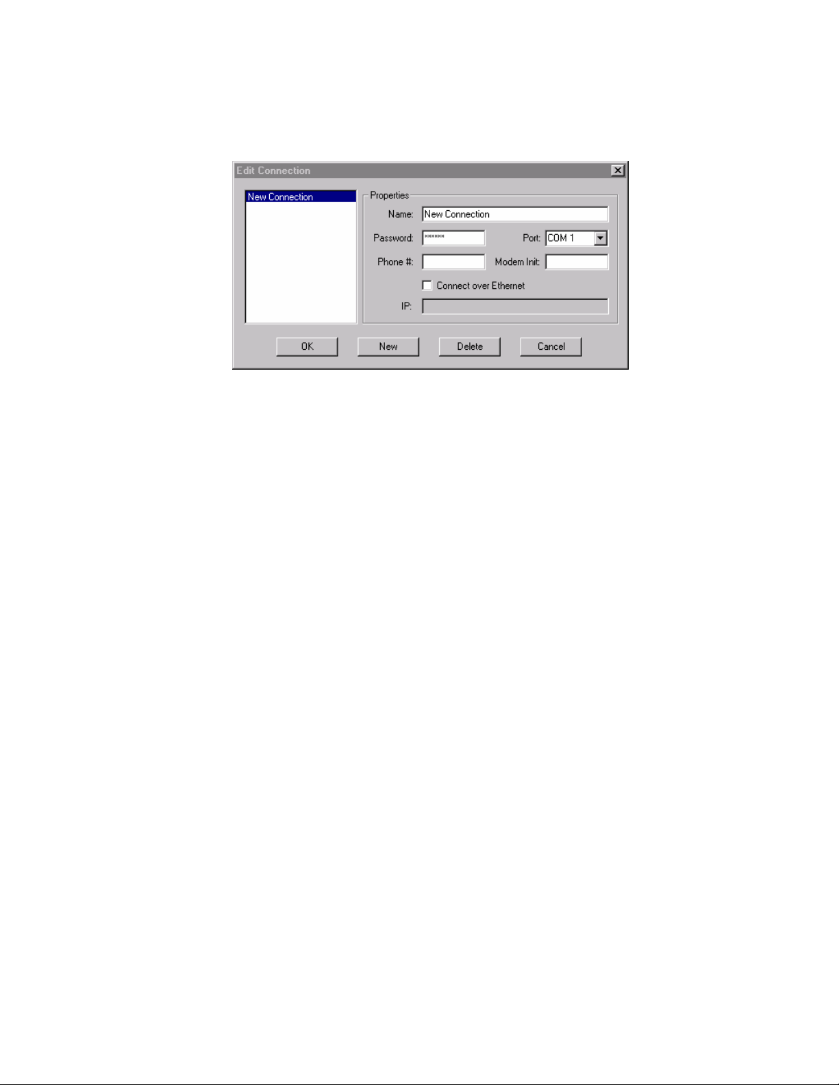
The Edit Connection Dialog Box
Under the Options Menu, select “Edit Connection”. A new window will open, and a default “New Connection”
option will be displayed. Enter required information into each of the configuration boxes.
Edit Connection Menu in Omnia.Multicast Remote Control
In the left side of the currently contained
in the 'connect.dat' configuration file. Connect.dat will be created in whatever folder the Omnia remote program
is started from. The specific names in the list are derived from the information that was entered into the
“Name:” box when each connection was first set up. In the Properties Window of the dialog box, it's a good
idea to edit the connection name to match the type of connection you wish to configure. The three available
connection types are:
• via Direc
• via Modem
• via TCP/IP E
Connectio Dialup” if
using a modem may be used. This naming convention is not mandatory, but it will help keep things tidy if you
decide to use Omnia.Multicast Remote Control to connect to several Omnia.Multicast units.
(Note: Use New to create any additional connection entries. Use Delete to remove any unu
any entry in the connection list to edit its fields. Use Cancel to exit without making changes.)
To set up a connection:
n names such as “Serial” if using the RS-232 port, “Network” if using the Ethernet port or “
1. Enter the nam
create according to the Omnia they connect to, or even by the method of connection. For instance,
the name box could contain entries like “WXXX Omnia”, “WYYY Omnia”, “WXXX Omnia by
Modem”, WYYY Omnia by Network”, etc.
“Edit Connection” window will be the list of any connections that are
t Serial
thernet (if optional Ethernet interface is installed in the Omnia.Multicast)
sed entries. Select
e of the connection in the “Name” box. It is helpful to name the connections you
2. rd for the Omnia.Multicast that you wish to make a
3. he
In the password box, enter the login passwo
connection to. The factory default password is “tomtom” (all lower case). If you leave the
password box blank, the Omnia will prompt you for the password each time you try to connect.
If you wish to connect over a network (using the optional Ethernet interface), you must check t
box “Connect over Ethernet”. When you do this, the parameters required for direct serial or dial-in
via modem will be grayed out. Then, only the TCP/IP address of the Omnia that you wish to
connect to must be entered. Note: If you are connecting via Direct Serial or Modem, you should
not check the “Connect over Ethernet” box!
46
Page 47

4.
If connecting via Direct Serial or Modem, then select the COM port that you wish to use on your
PC. This COM port should be configured in
support, but in any case, should be set to at least 57,600 bps.
Windows for the highest baud rate that your PC will
5.
6. lephone number of the modem that is
7.
If you need to u e “Modem Init” string box. If you
requ a mo nnect string within the
ire dem initialization string and feel more comfortable building the entire co
“Phone #” box you may do this. See “Using Custom Modem Initialization Strings” for more information.
If your connection attempt times out before the Omnia can answer, you can increase the value (in seconds) of
the “Connection Timeout” setting. This value sets the amount of time the software will wait for the carrie
from the Omnia’s modem before timing out and hanging up the computer’s modem.
Omnia Remote Control supports a wide variety of Hayes command set compatible modems. If you have
difficulty using your modem, you may call Omnia Customer Support for assistance,
information about your modem as possible before doing so.
If connecting via Direct Serial, no other information is required.
If connecting via Modem, in the “Phone #” box, enter the te
connected to the Omnia at the remote site.
Omnia Remote program to attempt a connection via modem!
Click on OK to save all the changes and close the Edit Connection dialog.
se a Modem Initialization string, you may enter it into th
Any characters present in the “Phone #” box signal the
but please gather as much
r tone
On the Omnia Side...
Remote Control Using the Optional Omnia PCMCIA Modem
Before use, ensure that the Omni PCMCIA modem card is fully inserted into the lower PC Card slot
on the back of the Omnia. Press on the modem card's “XJACK” conne
jack. Using a standard RJ-11cable, connect your telephone line to the Om
telephone number corresponding to this line, as you will need it later when you configure the Omnia Remote.
a-approved
ctor to extend the modular telephone
nia modem. Make a note of the
Note: The modem card can only be safely installed and removed when the Omnia's power is off. Only the
PCMCIA modem card supplied by Telos Omnia has been tested and approved by Telos Omnia. We cann
ensure correct operation of any other modem card with the Omnia.Multicast, nor can we provide support for
such non-approved cards.
ot
Remote Control Using a External Hayes Compatible Modem
The Omnia supports nearly
support the widest possible variety of externally connected serial device
does
where this has prevented an externally connected modem from operating properly. The externally connected
modem will need to auto-detect one of the Omnia's three rear panel serial port's baud rates (9,600, 19200, and
57,600). Because the Omnia and the modem are
modem) cable between them.
support hardware or software handshaking. This is of no concern, and we are aware of no instances
not
every Hayes command set compatible modem available. Please note that in order to
s the Omnia.Multicast's RS-232 port
both DCE devices, you will need to use a crossover (null
Remote Control Using a Direct RS-232 Connection for Local Communications
When a computer can be located near the Omnia.Multicast, it may be convenient to use a direct serial cable
connection rather than dial up. Use a standard, straight-through serial cable -- null-modem cable
A typical serial cable will need a DB-25 male connector for the Omnia.Multicast end, and p
female connector on the computer end. You should verify the exact type required by your computer.
s will not work!
robably a DB-9
47
Page 48

Remote Control Using Ethernet
The Omnia.Multicast can be controlled via Ethernet using the optional Omnia.Multicast Etherne
interface (Part number 2091-00013). This part supports connection via 10-base-T or 100-base-T Ethernet.
Installation and configuration of this h
interface. During initial configuration,
other port is supported by the Remote Control software. Once configuration is complete, connections behave
identically to any other method.
ardware is covered in separate instructions included with the hardware
the interface must be set up to respond to connections on port 3002. No
t hardware
Connecting via Direct Serial Connection
In the Edit Connection window,
default password is “tomtom”-lower case only!). The password may be changed at any time using the File
Menu “Change Password” option. Note that you must b
password, and that the password change becomes valid the
control. Changing the password here also affects the front panel password used to unlock or login to the unit.
Select the COM port that your computer will use under the drop down list box labeled “Port”. If the Omnia and
computer are connected by a straight through serial cable, you should be able to connect and control the
Omnia.Multicast locally using the remote control program.
The Omnia is designated as a DCE serial device, and has a DB-25
computer will typically be a DTE device, and will usually have either a DB-9 or DB-25
only connections between the same
DTE), the Omnia to PC cable should be a straight-through type! A null modem cable will not work!
create a New Connection and name it. Then fill in the Password box (the
e connected to the Omnia in order to change the
next time you attempt to log in with Omnia Remote
female RS-232 port connector. Your
male connector. Since
type of equipment require a null modem cable (DCE to DCE, or DTE to
Connecting via Modem
Configure a new connection, also entering the telephone number to which the Omnia.Multicast
Modem Card is connected. Then fill in the Password box (the default password is “tomtom”-lower case only!).
The password may be changed at a
be connected to the Omnia in order to change the password, and that the password change becomes valid the
next time you attempt to log in with Omnia Remote control. Changing the password here also affects the front
panel password used to unlock or login to the unit.
ny time using the File Menu “Change Password” option. Note that you must
’s optional
If your computer needs to dial an access code (such as “9”) to get an outside line, that digit must be entered as
well. Sometimes if the outgoing connection passes through a PBX, it might require a short pause between the
outside line access code and the telephone number
to have a comma inserted into it after the '9'. (In the standard Hayes command set, a comma is a “pause”
character). You may use as many commas (pauses) in the dialing string as necessary to get whatever delay you
require for your situation.
Example: suppose you need to connect to a remotely located Omnia and it is connected to telephone number
555-1234 in Area code 717. To make things more interesting, your local PBX system requires you to dial a “9”
to get an outside line. In th
long distance call. In this situation, the correct entry for the “Phone #” box would be:
9,17175551234
To enhance 'human readability', you could parse the telephone number entry with hyphens. Doing this has no
effect on the ability of the program to dial out. The entry in the Phone # box entry wou
9,1-717-555-1234
is case, you'll need to dial “9” to get an outside line, as well as a “1” because it is a
you're dialing. In this case, the telephone number will need
ld then be:
48
Page 49

Using a Custom Modem Initialization String
A custom Modem Initialization String is sometimes required in order to control the behavior of
special circumstances.
modifies how the m
provide the US standard 350/440 Hz dial tone, and in this case, you need to tell the modem to ignore it.
Edit Connection dialog box with “Modem Initialization String” edit box
The extra dialing commands that modify modem behavior should be entered into the “Modem Init:” box in the
Edit Connections menu. If you are “modem init string savvy”, you could ignore the “Modem Init:” box
altogether and place the complete dialing command string into the Phone # box. The choice is yours.
While there are many different initialization string possibilities, the most common one
odem handles dial tone. Sometimes the modem may be connected to a circuit that does not
the modem in
As pointed out earlier, a common customer need is the ability to tell the modem to ignore a non-standard dial
tone. For that situation, the most commonly used options are:
X0 - Disables both busy and dial tone detection.
X1 - Disable busy and dial tone detection.
X2 - Disable busy detection, enable dial tone detection.
X3 - Enable busy detection, disable dial tone detection.
X4 - Busy and dial tone detection enabled.
Given this information, a possible initialization string example configured to ignore the dial tone before dialing,
could be:
ATX0w,xyyyzzzz or ATX0w-,x-yyy-zzz
Where “AT” is the start of the standard modem command string, and;
Where “X0” tells the modem to ignore busy and dial tone detection, and.
Where “x” is the number to dial to reach an outside line (if required), and;
Where “,” is a pause, and;
Where “yyy” is the dialing prefix, and;
Where “zzzz” is the dialing suffix.
There are many resources on the World Wide Web pertaining to the possible Hayes command set initialization
string options. You can locate such resources by using the search text “Hayes Command Set” in your Internet
browser. Two such sites with resources that have been helpful are:
http://www.modemhelp.net/basicatcommand.shtml
http://www.modemexpress.com/
49
Page 50

Connecting via Ethernet Network
For Network connections, check the Connect over Ethernet box and enter the IP address of the
Omnia.Multicast in the box provided. The TCP/IP address entry format is: xxx.xxx.xxx.xxx. The TCP/IP
address of the Omnia.Multicast Ethernet hardware interface is set during initial configuration.
Technical note: the Omnia.Multicast Remote Control communicates with the Omnia.Multicast using a Telnet
session on Port 23. If you are unable to communicate with the Omnia through a network firewall, the first thing
to check is whether traffic on port 23 is being permitted.
Enter the password for the unit in the Password box. If nothing is entered, you will be asked for the password at
the time you connect to the remote Omnia. The default passwords for Ethernet remote connections are the same
as the front panel passwords:
Normal: “vito” (all lower case)
Engineer: “tomtom” (all lower case)
The Remote Control software allows multiple connection profiles to be created so that a mix of connection
types (Direct, nicating with
different Omnias at different locations, connected by different means.
When all items have been entered, select OK.
Serial, TCP/IP) may be used. This allows the program to easily support commu
Note: These connection settings are stored in a small binary file named located in the same folder
as the remote program.
connect.dat
50
Page 51

Using the Remote Control
Establishing a Remote Connection
To establish a connection with the remotely located Omnia.Multicast, return to the Options Menu and select
Connect, which brings up a list of connections you have defined. Double-click on the name of the desired
connection, or highlight it to select it and press OK. The
you should see the bargraph meters become active when a connection has been established.
connection will be established after a short pause, and
Omnia.Multicast Remote Control after connection is made. Note that the currently selected
Preset and the Omnia's actual System time are being displayed.
Use Cancel to leave the dialog box without making any connection.
You can choose to have the program automatically establish a connection by going to the Options Menu,
selecting Auto-Connect to Last. Then the program will always connect to the Omnia.Multicast using the last-
used startup connection entry.
Note that if you have not entered a Password while editing the connection type, you will be prompted for it each
time you connect to the Omnia!
Terminating a Connection
From the Options Menu, select Disconnect. Closing the program will also terminate any connections.
Remote Features
The Remote Control Program for Omnia.Multicast provides all the features of the front panel, displayed in an
easy-to-use format. It adds these enhancements:
• Multiple control windows may be open at the same time.
• The scroll wheel on mice so equipped is supported for fast, easy adjustment of parameters.
• The ability to save, load, and print presets and system parameters to the computer. (in the File Menu)
This is very handy for reference and backup purposes.
51
Page 52

Using a Terminal Program and Direct Connection
It is sometimes useful to use a Direct Serial
HyperTerminal to gain access to the Omnia's command line interface. While operating the Omnia in this
manner is certainly not for beginners, the information that can be captured from the rear-panel RS-232 port,
especially during system boot-up, can be very useful for troubleshooting purposes. Upon occasion, Omnia
Customer Support personnel may ask you to capture such data from the rear port if it seems necessary.
The serial communications parameters of the terminal program should be set to:
8 Data Bits
No Data Parity (None)
1 Stop Bit
Flow Control (None)
The Baud rate (bits per second) must be set to match the setting in the Omnia.Multicast’s Utility Menu. Make
sure however that the maximum allowed baud rate (set in the Windows Device Manager) of the serial port
being used is set at least as high as the desired baud rate. Setting this to the highest available setting is fine.
Once these parameters have been set, one can now log onto the Omnia.Multicast by typing “login tomtom”
(enter) at the >> prompt. If the >> prompt does not show up, try typing “echo on” (enter).
Connection and a terminal program such as Windows
52
Page 53

Trigger Interface and Script Editor
Overview of the Trigger Script Editor
The Omnia.Multicast Remote Control software contains a special script editor that allows the programming of
complicated system parameter changes, which can be “triggered” by logic state changes on the rear-panel
“Interface” connector.
“Edit Trigger Scripts” dialog box as opened under “Options”, “Edit Trigger Scripts”
Using Trigger Scripts, you can make the Omnia.Multicast do things with contact closures that would normally
need to be done either by manual intervention at the front panel, or via Omnia.Multicast remote control. There
are EIGHT Trigger Inputs available, and they respond to
voltage levels
on the rear-panel “Interface” connector.
Trigger Control by Dry Contact Closures
The simplest way to manipulate a Trigger Input is through simple contact closures to ground. Connecting a
Trigger Input to ground initiates the programmed function associated with the “Trigger LOW” command, and
moving the connector pin from a grounded to a floating condition issues the “Trigger HIGH” command.
Trigger Control by Applied Voltages
The Trigger Inputs are also capable of operating with a DC voltage applied, as long as such voltage does not
exceed 25 volts DC. Applied voltages that are more than +1.25 volts DC on the trigger input result in a Trigger
HIGH state, while voltages less than +1.25 volts result in a Trigger LOW state. Therefore, if +12 volts DC is
applied, a logic “1”, or Trigger HIGH is sensed. If –12 volts DC is applied, a logic “0”, or Trigger LOW is
sensed. When nothing is connected to the Trigger Inputs, they normally float at approximately 3.5 volts, which
is a logic
HIGH.
What Can Trigger Scripts Control?
Virtually any aspect of the Omnia.Multicast operation can be controlled using the Trigger Script function.
Therefore, we'll explain some of the different types of operations that can be performed, and the different types
of commands that are required to perform each one.
53
Page 54

Some Common Uses of Trigger Scripts
• Switch from Stereo to L+R Mono
• Switch from L+R Mono to Stereo
• Switch the Omnia's audio input source from Analog to Digital
• Switch the Omnia's audio input from Digital to Analog
The Para, The Syspara, and Command Line Entries
What Is a “Para”?
In general, a 'para' is a variable that corresponds to one of the adjustable controls available within a Processing
Block. For instance, the Wide Band AGC Release Time is a 'para', in fact, it happens to be 'para' 3.
What Is a “Syspara”?
In general, a 'syspara' is a system parameter assigned to the basic operation of the “System”. Controls such as
the one for audio source selection, the mono operating mode, and the input or output level, each have a
“syspara” value associated with it.
What About Command Line Entries?
Just as 'paras' and 'sysparas' can manipulate the processing controls and system adjustments, there are higher
level commands available which do even more special things.
Usin
g The Trigger Script Editor
A Trigger Script is “written” using the Trigger Interface Script Editor that is contained within the Omnia
Remote Control software. The Script Editor runs in a separate window from the Remote Control window. The
Editor window is opened under the Options menu (Edit Trigger Scripts). To open the Script Editor window, the
computer running the Remote Software
Starting the Script Editor (Options / Edit Trigger Scripts) op
buttons along the left side select which trigger script number to display and edit. The top edit box shows the
script for the Trigger HIGH Command Script (contact open) for the selected input. The bottom edit box shows
the script for the Trigger LOW Command Script (contact closure) for that input.
Once a script has been entered, clicking the Test button checks the script syntax, and if correct, sends the
displayed script to the Omnia.Multicast for immed
alert dialogs that pop up to view the success or failure of the script. Note that executing the script in this manner
does not result in the script being downloaded or saved as a trigger script, it is simply run once to see if the
script, as written, actually works.
The buttons along the bottom of the window load, save, or download the current scripts being edited to the PC
Card. Click “Save to Card” to permanently store the current scripts on the PC Card in one file. Click “Load
from Card” to retr
to the PC Card, click “Apply” if further script editing will be done. Click “OK” to download the current scripts
and close the Script Editor window. Click “Cancel”
last “Apply” or “Save to Card.”
ieve previously saved scripts. To download the scripts for use in the processor without saving
be connected to and communicating with the Omnia.Multicast.
must
ens up the Script Editor window. The eight radio
iate execution. Use the command line window and/or any
to close the window, discarding any changes made since the
Note: If you have created Trigger Scripts and clicked “Apply” but not “Save to Card”, the Omnia will only
remember your scripts until you power it off.
54
Page 55

Once the scripts are downloaded into the proce
occurs o er the Remote Control application nor the Script Editor needs to be
connected for the tri
Note: y be encountered in the execution of it
will not be
n their assigned trigger input. Neith
gger scripts to execute.
When a trigger script is actually executed, any problems that ma
noted to the user.
ssor, they are executed when the appropriate logic transition
Script Command Definitions
The scripting commands available for use with presets are listed in bold
Presets
Note: After a preset is saved to the system, the Omnia knows them by their Index Number, not by their Preset
Name. Therefore, when selecting a preset, you use its index number. When saving presets, you use it
lettering (e.g., presets).
s name!
presets
preset <preset index #> Selects the preset by index # from the list of available presets
Example: preset 21 <enter> co
delete <preset index #> Deletes a prese
Example: delete 21 <enter> commands the Omnia.Multicast to remove preset number 21 from the index list.
rename <preset index #><name> Renames the preset by its index number.
Example: rename 21 BOOGY <enter> comm
save Saves the preset under its current name.
Note: Factory presets are permanent and cannot be written over. You must use the ‘saveas’ command when
saving changes made to a factory preset in order to save it as a unique name.
saveas Saves the preset under a different name.
Example: saveas BOOGY <enter> Commands the Omnia to save the current settings as preset BOOGY.
Lists all the currently available factory and user presets by index #.
mmands the Omnia.Multicast to load preset number 21 in the index list.
t from the preset index list by its index number.
ands the Omnia.Multicast to rename preset number 2.
Non-System Parameters (paras)
paras Lists the modifiable parameters available for the current preset in a table format.
Example: paras <enter> displays the parameters for the current preset:
paravalues <index #> Lists all possible values for the parameter at the given index number.
para <para index #> <parav
alue> Sets a new value for the selected parameter.
Omnia.Multicast System Parameters
A 'syspara' is an Omnia.Multicast System parameter. The System Parameters are assigned to controls which
govern overall operation, such as Input and Output Gains, etc. These parameters would NOT be saved with
individual presets, but instead are saved using the Save To Card option in the System menu.
To obtain a list of all System parameters, you use the command 'sysparas', which lists all of the adjustable
parameters in a table format with
displays the following table:
their current setting value in brackets. Example: typing sysparas <enter>
55
Page 56

1) Input Source [ANALOG] 2) Analog Gain [0]
3) Input Left [0.0dB] 4) Input Right [0.0dB]
5) Output Left [+4.0dB] 6) Output Right [+4.0dB]
15) Backlight [7
17) Headphones [-10.0dB]
20) Current State [ENABLED] 22) Input Phase [NORMAL]
24) Ctrl Port Baud [19200] 25) Mono Mode [Stereo]
32) LPF Freq [16kHz]
Setting New Syspara Values
To f h
ind the new value you wis to use for a particular Syspara:
sysparavalues <syspara index #> Lists all the possible values for any parameter.)
To set a
To reset
To sa l Sy tem set ings to the
new value for a Syspara:
syspara <syspara index #>[<sysparavalue index #>]
all System parameters back to their factory defaults:
sysdefaults Restores the system attributes back to their factory defaults.
ve al s t rear-panel memory card.
syssave Saves the system attributes to the Omnia PC Card.
0] 16) Contrast [50]
19) Editing Mode [EXPERT]
To l setting m th
oad the saved fro e rear-panel memory card:
sysload Loads the system attributes from the currently inserted Omnia PC Card.
Creating a Trigger Script
Now ting man
that the scrip com ds have been defined, let’s put them to work to create a Trigger Script. We’ll use
one of the most commonly requested operations that broadcasters want to easily accomplish: switching between
mono and stereo operation
This witch the
procedure can of course be done by manually using the Omnia.Multicast front panel controls to s
inpu ditor to create two scripts
t from stereo to mono left. But a far easier method is to use the Trigger Script E
that can be loaded into the processor to run in
scripts do just that—set the Omnia.Multicast t
closure and to then return to stereo operation when that same contact is opened.
In scripts, all lines that begin with “syspara” must be followed by two numbers that identif
number that is being set and that ID number's new value. The value numbers and their settings for the Pilot
Level were also shown. To list the values and parameter settings for any parameter, type in sysparavalues
followed by a space and then the parameter’s “syspara” number.
(The above “syspara
.
response to a single relay contact closure or open. The following
o automatically switch to mono in response to a sustained contact
y the parameter ID
s” table lists all of the available system parameter numbers.)
56
Page 57

Trigger Sc
In this exa e, we'll configure Tri o switch the Omnia.Multicast into
contact and switch back to st w ns again. To create this scri
click ra utton #1. Now click in th dit box to begin entering the T
Type:
syspara 2 2 <enter>
ript Example for Switching to Mono Operation
mpl gger Input # 1 t mono operation when the
closes ereo hen it ope pt, open up the Script Editor and
dio b e lower e rigger 1 “Trigger Low” script.
This command sets the syspara 2” says to edit the
Mono Mode
When finished, the contents of the Tr r LOW Command Script
syspara 2 2
If you
command 'syspara 2 4' instead of
setting. The “2” says select mono left.
you are igge box should look like:
wanted to use the sum of Left and Right channels for your mono source, we would have entered the
processor to switch the input to “mono left” when run. “
'syspara 2 2'.
Trigger Script Example for Switching to Stereo Operation
Now we'l eration when the
switch contacts open. In the Trigge
syspara
This tells the processor to switch the input to “Stereo.” “sysp
“1” says to
When you are finished, the contents of the Trigger HIGH C
syspara
These two commands are now a completed script for Trigge
each edit box. If no errors or other displays are shown, then your script is ready to be used or saved. An error
indication ommand is correct
and that the index numbers for the parameters or parameter values are correct.
l create a Trigger High Command Script, which will return the Omnia to stereo op
r HIGH Command Script box type in:
2 1 <enter>
ara 2” says to edit the Mono Mode setting. The
select stereo mode.
ommand Script box should look like:
2 1
r 1. To test the scripts, click the Test button above
typically indicates you have a “typo” in one of your command lines. Verify the c
In order to use the scripts, they mu
Previously entered scripts in the Omnia.Multicast’s memory are then replaced by your new scripts. To save the
edited Script Editor scripts to the PC Card, click Save to Card. To recall previously edited scripts, click Load
From Card. These can then be
To actually use the scripts you have just written requires that a sustained relay or a switch be connected between
trigger input 1 (pin 1) and ground (pin 5) on the Interface connector on the processor's back panel. Setting the
relay or switch on (shorting pins 1 and 5 together), then causes the Omnia.Multicast to follow the script for go
low (the unit switches to Mono Left operation). Opening the switch or relay will then cause the processor to
follow the go high script (the unit switches to stereo operation).
Multiple operations, including ones that are vastly more complicated than what we have presented here, such as
simultaneously changing to different presets when changing from stereo to mono, can be completed at the flip
of any one of the eight switches or relays connected to the Omnia.Multicast. And the eight relays or switches do
not have to be switched locally: Commands can even be initiated
contact closures is being used.
sent to the Omnia.Multicast by clicking Apply.
st be loaded into the Omnia.Multicast. This is done by clicking Apply.
by a network satellite when a receiver with
57
Page 58

Initiating Trigger Scripts via the Interface Connector
As we mentioned, trigger scripts give the user the ability to tie a series of commands to a simple high/low logic
change occurring on a pin of the 9-pin D-sub Interface connector on the unit’s rear panel.
The Pinout of the Omnia.Multicast rear-panel DB-9 Interface connector is as follows:
PIN 3 activates Trigger Script 8 PIN 8 activates Trigger Script 7
PIN 4 activates Trigger Sc
PIN 5 is connected to ground
Each pin that i
logic. To execute the Go Low script, a trigger input pin is connected via a sustained contact closure to pin 5
(ground). To execute a Go High script, the ground is
6, 7, 8, 9) is thus connected through a switch or relay to the Omnia.Mul
Let's review what we created for the example we showed you under “Using the Script Editor”. Whenever pin 1
is held low (the contact or switch is in a closed state), the Omnia.Multi
mode. When the pin 1
stereo operation (both lef
s to be used must first be programmed with a trigger script for the desired Go High and Go Low
PIN 1 activates Trigger Script 1 PIN 6 activates Trigger Script 2
PIN 2 activates Trigger Script 3 PIN 7 activates Trigger Script 4
ript 6 PIN 9 activates Trigger Script 5
removed from that pin. Each of the trigger pins (1, 2, 3, 4,
ticast’s ground on Pin 5.
cast will switch to and stay in mono
contact is subsequently opened, the Omnia.Multicast will switch back to and stay in
t and right input channels being used) as long as the contact is open.
“One Way Script” Functions
You may also create scripting functions t
opened. To do this, you use the Go LOW script only, and do not put any entries into the Go HIGH
Two possible uses
system time to an external standard, and remote re-booting of the Omnia.
for this very useful “Go LOW Only” Trigger Script trick are periodically setting the Omnia's
hat do NOT return to another value when the remote contacts are
script.
To use the Omnia's command line “Time” function to reset the Omnia's System Clock to midnight based on an
external contact closure (such as from an automation system or other time reference), the Trigger Script script
syntax would be:
Time 00 00 00 Sets the Omnia time to midnight. Note that colons are
Although time is displayed by the front panel display and its controller, it is actually being kept by the Omnia
motherboard. When resetting the System Time using trigger scripts, the change takes effect immediately at the
motherboard. Because the front panel 'fetches' time synchronization from the mothe
the front panel's confirmation of the time change may lag by a few seconds but the two will agree with each
other when updating takes place.
Another possible use of the one way Trigger Script script capability (although not strongly recommended) is the
remote 're-booting' of the Omnia. In that special case, there would be no Go High script entry. The Go Low
script for that function would simply read: warmboot
Remote re-booting of the unit carries with it several caveats:
• There will be a loss of audio while the system restarts. Analog and composite audio will continue to
run for approximately nine seconds, and then nine seconds of no audio will elapse while the DSP code
is reloaded.
If Omnia Remote Control is connected by a modem or direct serial connection at the time, it will be
•
disconnected and manual intervention will be required to reconnect.
not used as delimiters in this entry!
rboard every few seconds,
58
Page 59

• If Omnia Remote Control is connected by Ethernet
Omnia front panel will freeze. However, when the Omnia Remote control session is disconnected,
normal Omnia front panel operation will be restored. Manual intervention will b
Omnia Remote Control.
at the time, the meters on Omnia Remote and
e required to restart
• If you have not saved the System or Trigger Sc tings, they may be permanent
adjustments are saved in NVRAM and are not lost at power down.
Note: Remember not to include any commands that may potentially prompt the user, since a user
the Omnia.Multicast when the commands are executed.
Note: The remote control application does not have to be connected in
ript set ly lost. Preset
order for the scripts to execute.
may not be at
59
Page 60

C a
h pter 7: Troubleshooting
Operatio
and a co ications program. Detailed information about the Omnia's boot-up progress
may be
encountere
troubles echniques for isolating possible
Omnia.Multicast problems in the field, and also how to obtain help or repair service from Omnia.
nal problems with the Omnia.Multicast can sometimes be diagnosed using the rear-panel RS-232 port
mmon terminal commun
observed at its rear-panel RS-232 port, as well as viewing of any error messages that may be
d. This chapter explains the various boot up and error messages that may be encountered while
hooting the unit. We'll cover some basic troubleshooting t
To take complete advantage of this functionality, yo
Windows, or other operating system. It must be configured for a default baud rate of 19200, no h
andshaking, and using a terminal emulation for VT100. At Omnia, we commonly use the Hyperterminal
h
rogram that ships with Microsoft Windows
p
e the examples below for how we've set up our connection:
se
©
, but you can use whatever program you are familiar with. Please
u only need a standard terminal program for DOS,
ardware
©
Port Setup Parameters Terminal Emulation Parameters
Once these parameters have been entered and saved as a connection profile, they can be used to capture and
display (and print) the output of the Omnia.Multicast's RS-232 serial port during boot up. See the next page for
an example of a normal Omnia.Multicast boot up...
60
Page 61

Omnia Messages
Normal Boot-up Message
A healthy Omnia.Multicast running v 3.4.4 will transmit the following text on the rear panel serial port during
boot up:
Omnia BIOS Software 1.13
Work : BIOS v1.13...
Work: Downloading OS...
Work: Downloading OS...
Work: Downloading OS...
Work: Downloading OS...
Work: Downloading OS...
Work: Downloading OS...
Work: Downloading OS...
Work: Downloading OS...
Serial console intialized.
Querying motherboard...Rev. G motherboard detect
Work: Omnia 3.04.04...
Msg : Omnia 3.04.04...
Work: Omnia 3.04.04...
Work: System Storage...
Work: Omnia Card...
Work: Preset Table...
Msg: System: NET -- common: 2 specific: 1
Msg : set preset NO PROC (alg old:(null) alg new: a3_net)
Work: Load Algorithm...
Msg : Load Algorithm...
Work: Load Algorithm...
Work: Load Algorithm...
Work: Load Algorithm...
Work: Load DSPs...0
Work: Load DSPs...1
Work: Load DSPs...2
Work: Load DSPs...3
Work: Load DSPs...3
AE 0, proba y a rev board.
Msg: S/EBU: Unable to read 842 bl G
: L
Work oad DSPs...3
Work: Preset Table...
Work: Done!
Work: IO Card...
Work: Command System...
Work: Graphics...
Work: Graphics...
ed.
Omni
61
Page 62

Audio Failure Alarm
If no audio is applied to the Omnia,
approximately twenty seconds after bo
Flr : Audio failure: left input
Flr :
Audio failure: right input
Flr : Audio failure: left outpu
t outpuFlr : Audio failure: righ
he absence of an audio sou
In t rce, these “Audio failure” messages are normal. Note that the Omnia's audio
re trigger level is –37.5dB
failu FS, and the signal must remain at or below that level in order for the silence
ct algorithm to time out. It i
dete s possible to see these messages during normal programming if the audio input
l happens to fall below –37.
leve 5dBFS and remains there until the audio fail algorithm times out.
Au m
dio Restoration Alar
App ximately five seconds after audio has been restored to levels above –37.5dBFS, the following messages
ro
will
be seen:
Flr : Audio restored: left
Flr : Audio restored: righ
Flr : Audio restored: left
Flr : Audio restored: right
Not there to be audio Output failure messages but no audio Input failure message. This
e that it is possible for
mea Inputs, but that there is no output from the DSP chain.
ns that the unit is detecting applied audio at its
From t level adjustment controls (Input Menu).
the perspective of signal flow, the Input meters follow the inpu
This the Input Audio Failure comes from.
is also where the input to
input
t input
output
output
the following messages will be transmitted next on the RS-232 port,
ot up:
t
t
Dia Messages
gnostic and Error
In t to contact Telos / Omnia Customer Support for assistance, please see the section
he event that you need
enti
tled
Obtaining Service on Page 97 for contact information.
following error messag
The es will appear on the front panel screen:
Insufficient Memory
Description: This erro
factory presets) on
Cause: Too many presets ar
Resolution: Delete
! Save As Failed.
r will occur when trying to save a new preset while there are already 50 presets (including
the rear-panel PCMCIA card.
e saved to the rear-panel software card.
a preset
or two and then try the save operation again.
The llowing messages will only appear on the rear panel RS-232 Serial Port. See page 92 for instructions on
fo
how to access the serial port messages.
Work: Insert card to continue!!!
Description: The operating system cannot see the rear-panel PCMCIA memory card.
Cause: The rear-panel PCMCIA card is missing or not fully seated.
Resolution: Turn the power off and make sure that the card is fully inserted into the top card slot with the large
Omnia label facing up and the version number sticker facing down. The PC Card is keyed to prevent improper
insertion.
1/2” [12.70 mm]. This indicates the card is properly seated in the PCMCIA slot. If the card is properly seated and
this error still appears, contact Telos / Omnia Customer Support for assistance.
Gently
press the card into the slot until the black release button, to the right of the card, pops out about
62
Page 63

Card does not have valid OS!!!
Description: The contents of
no bootable image on the
Cause: The card may be damaged, its data corrupted or it may contain the wrong software version.
Resolution: Try a new rear-panel memory card of the correct software version for your unit.
No previous system foun
Description: The contents of th
memory card.
Cause: This error may show up w
or when the Omnia booted up for the first time after the non-volatile memory (NVRAM) has been cleared, su
after replacement of the battery.
Resolution: Simply click OK in the error dialog box and the error should clear. If not and the Omnia continue
show this error at each boot-up, contact Telos / Omnia Customer Support for assistance.
NVRAM failure
Description: The operating syst
Cause: The NVRAM on the mo
Resolution: Contact Telos / Omnia Customer Support for assistance.
Failed to
Description: The operating syste
Cause: The Real Time Clock ch
Resolution: Contact Telos / Omni
Dead battery, data lost.
Description: The Lithium battery used for system configuration backup is being reported as dead or battery v
is too low for reliable operation.
Resolution: Contact Telos / Omnia Customer Support for assistance.
Timed out loading DSP.
Failed DSP #x Bootstrap, contact CE.
Description: The operating system was no
IC's on the card.
Cause: One of the DSP cards or DSP chips may have failed.
Resolution: Contact Telos / Omnia Customer Support for a
Host command bit not clear
ERROR: read failed write address, DSP #x
escription: The operating system was unable to communicate with the DSP's host port.
D
Cause: Possible failure of DSP or motherboa
Resolution: Contact Telos / Omnia Customer Support for assistance.
Failed Routing, contact CE.
Description: The operating system was unable to establish the correct sign
ause: Possible failure of motherboard DSP controller / router chain components.
C
Resolution: Contact Telos / Omnia Customer Support for assistance.
initialize RTC
the rear-panel memory card do not match what the operating system expects or there is
card.
d in memory
e non-volatile RAM on the motherboard do not match what is on the rear-panel
hen the Omnia is booted up for the first time with a new rear-panel software card
em was unable to write to the non-volatile RAM on the motherboard.
therboard may have failed.
m could not initialize the Real Time Clock on the motherboard.
ip on the motherboard may have failed.
a Customer Support for assistance.
t able to initialize one of the Omnia’s DSP cards or one of the two DSP
ssistance.
rd DSP controller / router chain components.
al path routing through the DSP chain.
ch as
s to
oltage
Electrical and mechanical safety note!
Whe is top cover removed, you are exposed to potentially lethal voltages
n the Omnia is operated with its chass
and
high speed rotating fan blades.
Befo
re attempting to make voltage measurements, be forewarned that the power supply heat sinks are connected
to th
e AC power line. Avoid these areas whenever the AC power cable is attached to the Omnia.
ake measurements when the power supply's safety cover is removed.
to m
63
Never attempt
Page 64

forewarned that the two fans present a serious hazard to fingers, tools, and meter probes. The fan blades
Be
te at high speed and have very sharp edges. They can quickly and easily remove a fingertip (gee ... how do
rota
know this?) Coming into contact with a rotating fan blade will cause serious injury.
we
n reinstalling the top cover, make certain that all thirty screws are replaced, and that they are
Whe tightened to a
fit. Operating the unit with its cover removed
snug or without all of the retaining screws will void your warranty
may compromise the ability of the Omnia to operate in high RF environments.
and
Na
rrowing down problems
Whe
emb
arking on an in-depth problem-solving mission. Take time to carefully consider whether your unit falls into
any of the following states:
1. T there
he unit is totally dead. Is the power on? Is the line cord plugged into an outlet that has AC power? Is
an a power indication? Are the LCD screens blank,
udio input level? Is there an audio output level? Is there a
scra wer supply problem. If you wish to
mbled, or not illuminated? Symptoms like these might indicate a po
examine the switching type, and therefore requires a load in order to start up
and therboard
operate properly. Voltages measured when the power supply is not connected to the Omnia mo
may
not be correct.
2. T essing bargraphs are working. The
he unit has power, but there is no audio output although the proc
first he front panel jog-wheel is operational. Verification of front panel operation
thing to verify is whether t
help
s narrow down where the problem is. Look at the levels display. If there is input audio but no output audio
indi ion back to normal, then a hardware
cations, try cycling the unit’s pow
failu put audio, verify that the outputs are
e of some sort has occurred. If you get output levels but have no outr
con put connected to a digital device, or a digital output connected to an analog
nected correctly. An analog out
devi priate test generator to the output cables to verify analog/digital
ce won’t pass audio! Connect the appro
audi
o is making it to the next device.
The processing to cease. Using program material,
next condition to check is to see if the failure has caused the
chec a good indication that the basic DSP
k to see if the processing bargraphs are operating. If they are, then it’s
stru t processor is working. At this point, it would be a good idea to see if the
cture is sound and the system's hos
loss .g. the discrete left/right outputs or the AES/EBU output.
of audio is confined to only one output port, e
Che to a digital audio
ck the signal at each of these locations. If the signal is dead at all three, then this points
prob g, then it can be
lem after the dynamic processing DSP chips. If one of the output sections is not operatin
loca
lized to that specific section.
oubleshooting your On actually tr mnia.Multicast, try to ascertain some preliminary information first before
power supply, be aware that it is
er. If that doesn’t bring the operat
Not are operated from their own specialized Digital to Analog converters.
e: The discrete left/right outputs
The
refore, it's possible for one type of output to fail without affecting the other. Likewise, a failure in the
AES e system is operational.
/EBU driver section could result in the digital output being dead, while the rest of th
4. Unit will not boot and “Downloading OS” is displayed over and over. This usually indicates a corrupt
rear-panel PC software card. Try a different PC card containin
available. Contact Omnia Customer Support or your dealer to obtain a replacement card.
g the same style of Omnia software if one is
64
Page 65

Obtaining Service
• Omnia Customer Support personnel are available in Cleveland, Ohio, USA, M
9:00 A.M. and 6:00 P.M., Eastern Time. If outside the U.S.A., see below.
• Before contacting Omnia Customer Support, please have the serial number of the unit (located on
barcode sticker on the rear panel in this format: 4300XXYYYY) and a description of the symptoms/pr
ready for the technician.
• All units being returned to for service MUST have a Return Authorization (RA) number assigned to them first.
Units that are returned without a RA
• Return the Omnia in its original shipp
box protects it as well as possible. Damage caused by improper packaging is not covered under your war
• Loaner units are usually available on a first come, first served basis. Your Omnia Customer Support engi
will assist you with
the necessary arrangements
number will experience delays in service.
ing carton. For best treatment, shipping the Omnia in its original factory
Note: To ensure prompt service, the Return Authorization number must be written
prominently on or near the shipping label on the box!
Via the World Wide Web
onday through Friday between
a small
oblems
ranty!
neer
The Omnia Web sit
information, software updates, etc. The URL is:
e has a wide variety of information that may be useful for product support, applications
http://www.omniaaudio.com./
Via E-Mail
The customer service e-mail address for Omnia is: support@omniaaudio.com.
Via Phone & Mail (USA and non-European Countries)
Customer service is available by telephone, Monday – Friday between 9:00 A.M. and 6:00 P.M., USA Eastern
time zone.
Phone: +1.216.241.7225 Fax: +1.216. 241.4103
Shipping Information: Omnia Customer Service
2101 Superior Avenue
Cleveland, Ohio 44114 USA
Via Phone & Mail for Eu
Service is available from the Omnia Europe office in Freising, Germany.
Phone: +49 8161 42467 Fax: +49 8161 42402
Shipping Information: * Omnia Europe
Johannistraβe 6
D-85354 Freising, Germany
rope
65
Page 66

WARRANTY
This Wa o equipment, parts, software and
acce or
With th nly items, the Products are warranted to be free from defects in material and
wor a
Soft r
days from the da
This
imp p
surge p e.
EXCEPT FOR THE ABOVE-STATED WARRANTY, OMNIA M
IMPLIED (INCLUDING IMPLIED WARRANTIES OF MERCHA
PARTICULAR PURPOSE).
In no event will Omnia, its employees, agents or authorized dealers be liable for incidental or consequent
damages, or for loss, damage, or expense directly or indirectly arising from the use of any of the Produc
the inability to use any of the Products either separately or in combination wi
or from any other cause.
In order to invoke this W
stated warranty period and warranty coverage must be authorized by O
If Omnia authorizes the performance of warranty service, the defective Product must be delivered, shipping
prepaid, to: Omnia, 2101 Superior Avenue, Cleveland, Ohio 44114.
Omnia, at its option will either repair or replace the Products and such action shall be the full extent of
Omnia’s ob
to the party that sent the Products, and Omnia will pa
Omnia’s authorized d are not authorized to ass
in connection with the dealers’ sale of the Products.
Omnia products are to be used with registered protective interface devices which satisfy regulatory
requirements in their country of use.
rranty covers “the Products,” which are defined as the various audi
ss ies manufactured, sold and/or distributed by TLS Corp., d/b/a Omnia (hereinafter “Omnia”).
e exception of software-o
km nship for a period of two years from the date of receipt by the end-user.
wa e-only items are warranted to be free from defects in material and workmanship for a period of 90
te of receipt by the end-user.
rranty is void if the Products are subject to Acts of God, including (without limitation) lightning;
wa
ro er installation or misuse, including (without limitation) the failure to use telephone and power line
rotection devices; accident; neglect or damag
AKES NO WARRANTIES, EXPRESS OR
NTABILITY AND FITNESS FOR A
ts or
th other equipment or materials,
arranty, notice of a warranty claim must be received by Omnia within the above-
mnia.
ligation under this Warranty. After the Products are repaired or replaced Omnia will return them
y for the cost of shipping.
ealers ume for Omnia any additional obligations or liabilities
ial
66
 Loading...