

Page 1
OMNIA
AUDIO PROCESSOR
INSTALLATION & OPERATION MANUAL
A Telos Company
TEL: +1 (216) 241-3343 FAX: +1 (216) 241-4103 E-MAIL: info@omniaaudio.com www.omniaaudio.com
TEL: +49 81 61 42467 FAX: +49 81 61 42402 E-MAIL: europe@omniaaudio.com www.omniaaudio.com
CUTTING EDGE 2101 SUPERIOR AVENUE CLEVELAND, OH 44114
CUTTING EDGE EUROPE JOHANNISTRAßE 6 D-85354 FREISING GERMANY
revision 2.00
Page 2

G
R E E T I N G S !
elcome to Omnia, the embodiment of a fresh, new concept in broadcast or netcast signal
processing. Omnia applies an advanced design philosophy that yields performance and
W
amazing loudness, with none of that “digital grunge aftertaste!”
Omnia is a fully digital system that can be configured to match the processing needs of any broadcaster. For FM
broadcasters there’s the original versions: Omnia.fm or Omnia.fm.jr with integral stereo encoders; for AM
broadcasters there’s Omnia.am; for broadcasters using the DAB system there’s Omnia.dab; and for Internet
webcasters there’s Omnia.net. There are a number of accessories available including additional memory cards
and, for Omnia.fm users, a FM Composite Filter and three field-upgradable software modules to add processor
functionality: HOT, Veris and Space-EFX (which may also be combined with the HOT or Veris plug-in).
Omnia’s flexibility is built-into the design. Instead of keeping the processing algorithms on a set of EPROMs or
proprietary potted modules, the system’s DSP (Digital Signal Processing) resources are entirely configured
through software contained on a plug-in PC Card (PCMCIA-type). Even fundamental rearrangements of the
system architecture can be easily accomplished in the field by plugging in a new PC card or, by using the
flexibility heretofore unavailable. Omnia delivers crystal-clear highs, thundering bass and
supplied Windows-based remote control application, through remote software download via local serial RS-232
connection or via the Internet through the supplied plug-in modem card.
Omnia, the promise of digital. . . delivered.
ii
Page 3

T A B L E O F C O N T E N T S
Greetings ...................................................................... ii
Safety Instructions ....................................................... iv
Hazard / Warning Labels .............................................. v
Notices ......................................................................... vi
Specifications .............................................................vii
Warranty ....................................................................viii
1 - INST ALLATION
Omnia Preinstallation Tasks ...................................... 1-1
Internal Switch & Jumper Settings....................... 1-2
AC Environment ................................................... 1-3
Omnia Installation & Connections ............................ 1-4
2 - OMNIA OPERA TION
The Omnia User Interface ........................................ 2-1
Main Menu Orientation ........................................ 2-2
Omnia Menu Items ................................................... 2-3
Menu & Sub-menu Summary .............................. 2-4
Processing Presets .................................................... 2-5
Omnia Menu Selections ........................................... 2-8
Housekeeping ......................................................... 2-11
Bargraph Display Screens ...................................... 2-14
3 - PROCESSING OVERVIEW
The Omnia and Audio Processing............................. 3-1
4 - OMNIA.FM & FM.JR
Processor Location ................................................... 4-1
Omnia.fm Connections............................................. 4-2
Pre-Emphasis: Where to Insert? ............................... 4-3
Stereo Generator Menu Items................................... 4-4
Block Diagrams ........................................................ 4-5
Bargraph Displays .................................................... 4-5
Menu Tree................................................................. 4-6
5 - OMNIA.AM
Processor Location ................................................... 5-1
Processing Presets .................................................... 5-1
Omnia.am Adjustments ............................................ 5-1
Omnia.am Block Diagram........................................ 5-3
Menu Tree................................................................. 5-3
6 - OMNIA.DAB
Omnia.dab Block Diagram ....................................... 6-1
Omnia.dab Menu Tree.............................................. 6-2
7 -OMNIA.NET
Omnia.net Block Diagram........................................ 7-1
Omnia.net Menu Tree............................................... 7-2
8 - EDITING PRESETS
Clarifying your Processing Objectives...................... 8-1
Adjustment Procedure ......................................... 8-2
Interpreting Processing Displays.......................... 8-3
Expert Mode Parameter Editing ................................8- 4
Saving, Renaming & Deleting Presets ..................... 8-6
Getting the Sound You Want .................................... 8-7
9 - ACCESSORIES
Remote Control Software ......................................... 9-1
Installation ............................................................ 9-1
Use ........................................................................ 9-1
Trigger Interface Script Editor .................................. 9-2
Script Command Definitions................................ 9-3
Using the Script Editor ..........................................9-6
10 - TROUBLESHOOTING & SERVICE
Error Messages ....................................................... 10-1
Omnia Field Servicing............................................ 10-6
Omnia Troubleshooting Guide ............................... 10-7
Obtaining Service ................................................... 10-8
APPENDICES
CE Declaration of Conformity ................................... A
Omnia W orksheets...................................................... B
Omnia.fm.hot Software Module................................. C
Omnia.fm.veris Software Module .............................. D
Omnia.fm.sp Software Module ................................... E
iii
revision 2.00
Page 4

S A F E T Y I N S T R U C T I O N S
1. Read All Instructions. All safety and operating
instructions must be read before operating the
product.
2. Retain All Instructions. All safety and operating
instructions must be retained for future reference.
3. Heed All Warnings. All warnings on the product
and those listed in the operating instructions must
be adhered to.
4. Follow All Instructions. All operating and prod-
uct usage instructions must be followed.
5. Heat. This product must be situated away from
any heat sources such as radiators, heat registers, stoves , or other products (including power amplifiers) that produce heat.
6. Ventilation. Slots and openings in the product
are provided for ventilation. They ensure reliable
operation of the product, keeping it from ov erheating. These openings must not be b loc ked nor co vered during operation. This product should not be
placed into a rack unless proper ventilation is provided through following the manuf acturer’ s recommended installation procedures.
7. Water and Moisture. Do not use this product
near water—for example; near a bath tub, wash
bowl, kitchen sink or laundry tub; in a wet basement; or near a swimming pool or the like.
8. Attachments. Do not use any attachments not
recommended by the product manufacturer as the y
may cause hazards.
9. Power Sources. This product must be operated
from the type of power source indicated on the
marking label and in the installation instructions. If
you are not sure of the type of power supplied to
your facility, consult your local power company.
10. Grounding and Polarization. This product is
equipped with a polarized AC plug with integral
safety ground pin. Do not def eat the safety ground
in any manner.
11. Power Cor d Protection. P ower supply cords must
be routed so that they are not likely to be walked
on nor pinched by items placed upon or against
them. Pay particular attention to the cords at AC
wall plugs and convenience receptacles, and at
the point where the cord plugs into the product.
12. Lightning. For added protection for this product
during a lightning storm, or when it is left unattended and unused for long periods of time, unplug it from the AC wall outlet. This will prevent
damage to the product due to lightning and power
line surges.
13. Overloading. Do not overload AC wall outlets,
extension cords, or integral convenience outlets
as this can result in a fire or electric shock hazard.
14. Object and Liquid Entry. Ne ver push objects of
any kind into this product through openings as
they may touch dangerous voltage points or shortout parts that could result in a fire or electric shock.
Never spill liquid of any kind on the product.
15. Accessories. Do not place this product on an
unstable cart, stand, tripod, bracket, or table. The
product may fall, causing serious damage to a
child or adult, and serious damage to the product. Any mounting of the product needs to follow
manufacturer’s installation instr uctions.
16. A Product and Cart Combination should be
moved with care. Quick stops, excessive force,
and uneven surfaces ma y cause the product and
the cart combination to overturn.
17. Servicing. Refer all servicing to qualified servicing personnel.
18. Damage Requiring Service. Unplug this prod-
uct from the wall AC outlet and refer servicing to
qualified service personnel under the following
conditions:
a. When the AC cord or plug is damaged.
b . If liquid has been spilled or objects have f allen
into the product.
c. If the product has been exposed to rain or
water.
d. If the product does not operate normally
(following operating instructions).
e. If the product has been dropped or damaged
in any way.
f. When the product exhibits a distinct change
in performance. This indicates a need for service.
19. Replacement Parts. When replacement parts
are required, be sure the service technician has
used replacement parts specified by the manufacturer or that have the same characteristics as
the original parts. Unauthorized substitutions may
result in fire, electric shock, or other hazards.
20. Safety Check. Upon completion of any repairs
to this product, ask the service technician to perform safety checks to determine that the product
is in proper operating condition.
21. Cleaning. Do not use liquid cleaners or aerosol
cleaners. Use only a damp cloth for cleaning.
iv
Page 5
H A Z A R D / W A R N I N G L A B E L S
CAUTION
RISK OF ELECTRIC SHOCK
DO NOT OPEN
WARNING: SHOCK HAZARD - DO NOT OPEN
A VIS: RISQUE DE CHOC ELECTRIQUE - NE PAS OUVRIR
CAUTION: TO REDUCE THE RISK OF ELECTRIC SHOCK, DO
NOT REMOVE ANY COVER OR PANEL. NO USER
SERVICEABLE PARTS INSIDE. REFER SERVICING TO
QUALIFIED SERVICE PERSONNEL.
WARNING: TO REDUCE THE RISK OF FIRE OR ELECTRIC
SHOCK, DO NOT EXPOSE THE OMNIA TO RAIN OR MOISTURE.
The Exclamation Point symbol,
within an equilateral triangle, alerts the
user to the presence of important operating and maintenance (servicing) instructions in product literature and instruction manuals.
WARNING—This equipment generates, uses and can radiate radio frequency energy. If not installed
and used in accordance with the instructions in this manual it may cause interference to radio
communications. It has been tested and found to comply within the limits for a Class A computing
device (pursuant to Subpart J of Part 15 FCC Rules), which are designed to provide reasonable
protection against such interference when operated in a commercial environment. Operation of this
equipment in a residential area is likely to cause interference, in which case the user, at his own
expense, will be required to take whatever measures may be required to correct the interference.
CANADA WARNING—This digital apparatus does not exceed the Class A limits for radio noise
emissions set out in the Radio Interference Regulations of the Canadian Department of Communications. Le present appareil numerique n’emet pas de bruits radioelectriques depassant les limits
applicables aux brouillage radioelectrique edicte par le ministere des Comminications du Canada.
CE CONFORMANCE—This device complies with the requirements of the EEC Council Directives:
93/68/EEC (CE Marking); 73/23/EEC (safety—low voltage directive); 89/336/EEC (electromagnetic
compatibility). Conformity is declared to these standards: EN50081-1, EN50082-1.
The Lightning Flash With A rrow-
head symbol, within an equilateral triangle, alerts the user to the presence of
uninsulated dangerous voltage within
the product’s enclosure that may be of
sufficient magnitude to constitute a risk
of electric shock.
LITHIUM BATTERY CAUTION—Danger of explosion if the internal lithium battery is replaced
incorrectly. Replace only with the same or equivalent type recommended by the manufacturer.
Dispose of used batteries according to the battery manufacturer’s instructions.
USE OF SHIELDED CABLING—To conform to the CE requirements for High Frequency
radiation, shielded cables must be used for all audio and data connections. For analog audio and
digital connections, the cable shield must connect to the XLR-type connector shell (chassis ground).
v
revision 2.00
Page 6
N O T I C E S
All versions, claims of compatibility, trademarks, etc. of hardware and software products not made by Cutting
Edge, but mentioned in this manual or other accompanying material, are informational only. Cutting Edge
makes no endorsement of any particular product for any purpose, nor claims any responsibility for its operation
or the accuracy of the presentation.
Warranty Registration and Software Updates
Omnia’s operation is almost entirely determined by software. A continuous program of improvement ensures
that the product remains at the “cutting edge.” In order to be notified of new software releases, be sure to fax or
mail in the registration form.
Trademarks
Cutting Edge, the Cutting Edge logo, Omnia.fm, Omnia.fm.jr and “The Promise of Digital…Delivered!” are
trademarks of TLS Corporation. All other trademarks mentioned in this work are the property of their respective
holders.
Copyright
Copyright ©1997-2000 TLS Corporation. All rights reserved. Published by Cutting Edge, who reserves the
right to make improvements or changes to the products described herein (which may affect the product
specifications) and to revise this manual as required without notice.
Repair Procedures
You must contact Cutting Edge for a Return Authorization number before returning any products. Packages
without proper authorization may be refused. Write the RA number on the shipping label side of the returned
package. Be sure to adequately insure your shipment. Customers in North America can contact Cutting Edge
customer support at +1 (216) 241-3343. In Europe, Contact Cutting Edge Europe at +49 81 61 42467
(Germany). All other customers should contact their local Cutting Edge dealer to verify the problem and contact
Cutting Edge to arrange for repair. Refer to Chapter 10: Troubleshooting & Service for more details.
Caution
The installation and servicing instructions presented in this manual are for use by qualified
installation and service personnel only. To avoid electric shock, do not perform any servicing other
than that contained in the operating instructions unless you are qualified to do so. Refer all
servicing to qualified personnel.
Warning
To reduce the risk of electrical shock, do not expose this product to rain or moisture.
vi
Page 7

S P E C I F I C A T I O N S
All measurements referenced to 100% output. It is not possible to quantify the specifications of the gain
controlling functions of the AGC and limiter sections due to the dynamic nature of the Omnia system under
program conditions. To properly evaluate these functions, there is only one known precise set of test gear for
that—your ears! Listen and judge carefully.
Audio performance
• Frequency Response: ±0.2 dB, 50 Hz - 15 kHz (50 Hz - 10 kHz for Omnia.am)
• System Distortion: 0.017% THD, flat or de-emphasized
• Signal-to-Noise Ratio: >80 dB, flat or de-emphasized
• Channel Separation: >85 dB, 10 Hz - 15 kHz (50 Hz - 10 kHz for Omnia.am)
Analog I/O Section
• Left & Right Audio Inputs: 10 k load impedance, electronically balanced bridging input, 20-bit analog-to-digital converter
• Maximum Input Level: +24 dBu
• Connector: XLR, female, EMI suppressed
• Discrete Left/Right Audio Outputs: 600 Ω load or greater, electronically balanced, 18-bit digital-to-analog converter,
flat frequency response or pre-emphasized (50 or 75 µs)
• Connector: XLR, male, EMI suppressed
Digital I/O Section
• Configuration: Stereo AES/EBU
• Input Sampling Rates: 32 kHz, 44.1 kHz, 48 kHz, sample rate converter provided
• Input Connector: XLR, female, EMI suppressed, balanced and floating
• Output Sampling Rate: 48 kHz
• Output Connector: XLR, male, EMI suppressed, balanced and floating
Composite I/O Section (Omnia.fm and Omnia.fm.jr only)
• SCA / RBDS Subcarrier Input: BNC, unbalanced
• Impedance: 1 k or greater load
• Signal: 53 kHz subcarrier is summed into composite output.
• Software controls: Input level, Output level High pass filter
• Multiplexed Output Connectors: Two BNC, unbalanced
Pilot Output (Omnia.fm and Omnia.fm.jr only)
• Connector: BNC, unbalanced
• Signal: Square-wave reference signal for RBDS or other 57 kHz subcarrier service
• Level: 0 – 1 V p-p (typ). Maximum output 5 V p-p.
• Software control: Output level
• Composite Output Level: 0 – 10 Vp-p, software adjustable
Computer Interface
• Configuration: RS-232 (DB-25 connector) for local serial connection. Optional PC Card modem for dial-up connection.
• Communications: Windows®-based Omnia Remote Control application (supplied).
Remote Control Interface
• Configuration: Eight software-controlled (through the supplied remote application) remote inputs sensing both go low
and go high transitions.
• Connector: DB-9, EMI suppressed.
Power
• Universal power supply accepts 100-240 VAC, 50-60 Hz, 50 VA.
• Connector: IEC, detachable 3-wire power cord, EMI suppressed.
Dimensions & Weight
• 19" wide x 16.25" deep x 5.25" high (48.3 x 41.3 x 13.4 cm)
• 32 lbs. (14.5kg), net
vii
In the interests of product improvement, Cutting Edge reserves the right to change, add or modify any
specification.
revision 2.00
Page 8

W A R R A N T Y
his Warranty covers “the Products,” which are defined as the various audio equipment, parts, software
and accessories manufactured, sold and/or distributed by TLS Corp., d/b/a Cutting Edge (hereinafter
T
With the exception of software-only items, the Products are warranted to be free from defects in material and
workmanship for a period of two years from the date of receipt by the end-user. Software-only items are
warranted to be free from defects in material and workmanship for a period of 90 days from the date of receipt
by the end-user.
This warranty is void if the Products are subject to Acts of God, including (without limitation) lightning;
improper installation or misuse, including (without limitation) the failure to use telephone and power line surge
protection devices; accident; neglect or damage.
EXCEPT FOR THE ABOVE-STATED WARRANTY, CUTTING EDGE MAKES NO WARRANTIES,
EXPRESS OR IMPLIED (INCLUDING IMPLIED WARRANTIES OF MERCHANTABILITY AND
FITNESS FOR A PARTICULAR PURPOSE).
In no event will Cutting Edge, its employees, agents or authorized dealers be liable for incidental or
consequential damages, or for loss, damage, or expense directly or indirectly arising from the use of any of the
Products or the inability to use any of the Products either separately or in combination with other equipment or
materials, or from any other cause.
“Cutting Edge”).
In order to invoke this Warranty, notice of a warranty claim must be received by Cutting Edge within the abovestated warranty period and warranty coverage must be authorized by Cutting Edge. If Cutting Edge authorizes
the performance of warranty service, the defective Product must be delivered, shipping prepaid, to: Cutting
Edge, 2101 Superior Avenue, Cleveland, Ohio 44114.
Cutting Edge, at its option will either repair or replace the Products and such action shall be the full extent of
Cutting Edge’s obligation under this Warranty. After the Products are repaired or replaced, Cutting Edge will
return them to the party that sent the Products, and Cutting Edge will pay for the cost of shipping.
Cutting Edge’s authorized dealers are not authorized to assume for Cutting Edge any additional obligations or
liabilities in connection with the dealers’ sale of the Products.
Cutting Edge products are to be used with registered protective interface devices which satisfy regulatory
requirements in their country of use.
viii
Page 9
1
I
N S T A L L A T I O N
ven though we believe the Omnia is the easiest processor to install in its class, please take a few minutes
to read through this chapter before proceeding with the installation.
E
Omnia Preinstallation Tasks
This section offers common procedures for installing any version Omnia processor. Additional model-specific
information is given in the chapters on specific versions (Omnia.fm and .fm.jr in Chapter 4, Omnia.am in
Chapter 5, Omnia.dab in Chapter 6 and Omnia.net in Chapter 7).
Omnia Components
By now, you’ve unpacked the shipping carton to at least gain access to this manual. Be sure to inspect the
Omnia and shipping carton for any shipping damage, which must be reported to your carrier for any claims.
The Omnia shipping box includes the following components:
➤ Omnia processor (containing the DSP hardware)
➤ Omnia PC card (holding the DSP software)
➤ Omnia modem card
➤ Omnia Remote Control program (on a single 3 1/2" floppy disk)
➤ Omnia Operating Manual
➤ Warranty Registration Card (fill it out and return it)
➤ IEC Power Cord
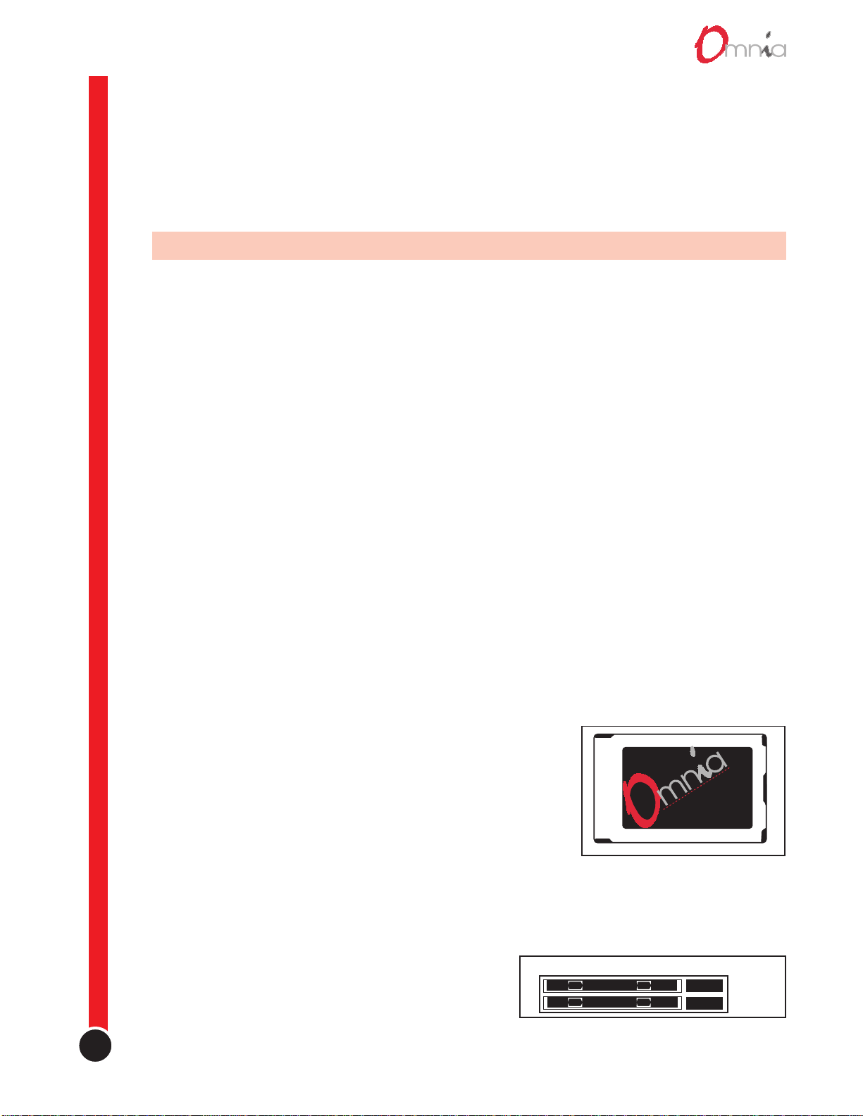
PC Card & Modem Card Installation
Before physically installing Omnia, or even plugging in the power
cord, make sure the Omnia PC Card and Omnia modem card are
installed into the two card slots on the back panel. Installation or
removal must be done with the power off unless directed otherwise.
The PC Card is inserted into the top card slot (Memory) with the
Omnia label facing up. Insert the Modem Card into the bottom card
slot (Modem) below the Omnia PC Card. Both the PC Card and
Modem Card are keyed to prevent mis-insertion. Press the cards into
the slot until their release buttons, to the right of the cards, pop out
about 1/2" [12.70 mm]. This indicates the cards are properly seated
in the PCMCIA slots.
P C C A R D
Omnia PC Card, label side
1-1
Note: You must use the modem card supplied with your
Omnia, no other modem cards are approved for use at this
time. We cannot assume correct operation of any other
modem card, nor can we provide support.
EXPANSION CARDS
MEMORY
MODEM
Rear Panel PC Card Slots
revision 2.0
Page 10
Installation
The PC Card that is used in Omnia is not a generic PCMCIA card that you might find in a local computer
store. It’s a card that is specifically designed for this product. If you insert a card of unknown origin, you risk
extensive damage to the unit and a complete voiding of the warranty!
Note: The Omnia PC Card must remain in the carriage unless you are prompted by the system to remove it.
Randomly removing the Omnia PC Card without system instruction may cause unpredictable operation and PC
Card data damage.
During operation of the Omnia, it is possible to remove the Omnia PC Card without interrupting the processing.
There are a few Omnia PC Card utilities that can be performed which require this. They are described in
Housekeeping in Chapter 2, Omnia Operation.
The Omnia is normally installed into a 19" equipment rack. But, before rack mounting the Omnia, ensure that
the internal jumper and switch positions are appropriately set for your installation as outlined in the next
section. Also, refer to the chapter on your model Omnia for additional information on where to locate your
Omnia processor.
Internal Switch & Jumper Settings
There is one internal AGC switch (applicable to any
model Omnia that’s using the analog inputs) and two
jumpers (applicable only to Omnia.fm’s Composite
outputs) that may need to be changed from their factory
defaults. Read through the switch and jumper
descriptions to determine if they need to be changed for
your installation.
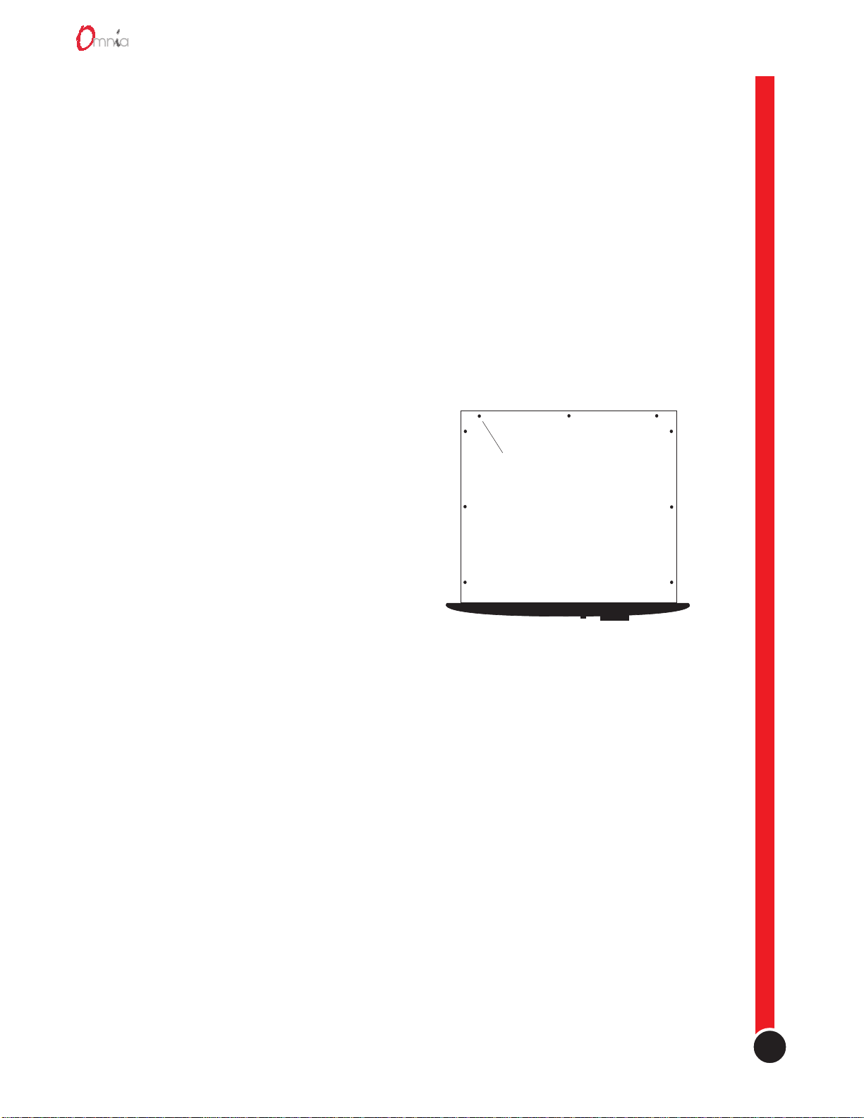
REMOVE NINE SCREWS
TO REMOVE COVER
If they need to be changed, the top cover of the Omnia
must be removed. Use care when working inside the
Omnia. Take appropriate measures to avoid product
damage due to static discharge.
Place the Omnia on an antistatic work surface,
Omnia Top Cover Removal
unconnected to AC power, before removing the top cover
(held in place by nine #1 Phillips screws).
Analog Input Headroom Protection Limiter
When the analog inputs are being used, an analog input protection limiter is engaged by default. This very fastacting peak limiter is set to respond to any signal peak that approaches within 2 dB of clipping the 20-bit A/D
converter. Since the operating level is nominally about 18 - 20 dB below the clip level, the limiter should never
become active. However, should a condition arise where the audio level threatens clipping in the A/D converter,
the limiter activates to prevent one of the nastiest forms of distortion.
Even though this limiter uses a high quality VCA, there may be those “audiophiles” who wish to disable the
limiter. This is done by changing a slide switch on the A/D board inside the unit. The A/D board is a square
“daughter” board that sits on the motherboard near the rear panel XLR connectors as shown in the illustration.
A single blue slide switch, labeled AGC, is on this board. Use a small screwdriver to slide the switch away from
the In position. The limiter is now defeated.
Note: When the limiter is defeated, so is the Analog Gain software parameter that sets the input sensitivity. With
the limiter Out, the input sensitivity is fixed at +4 dB.
1-2
Page 11
Chapter 1
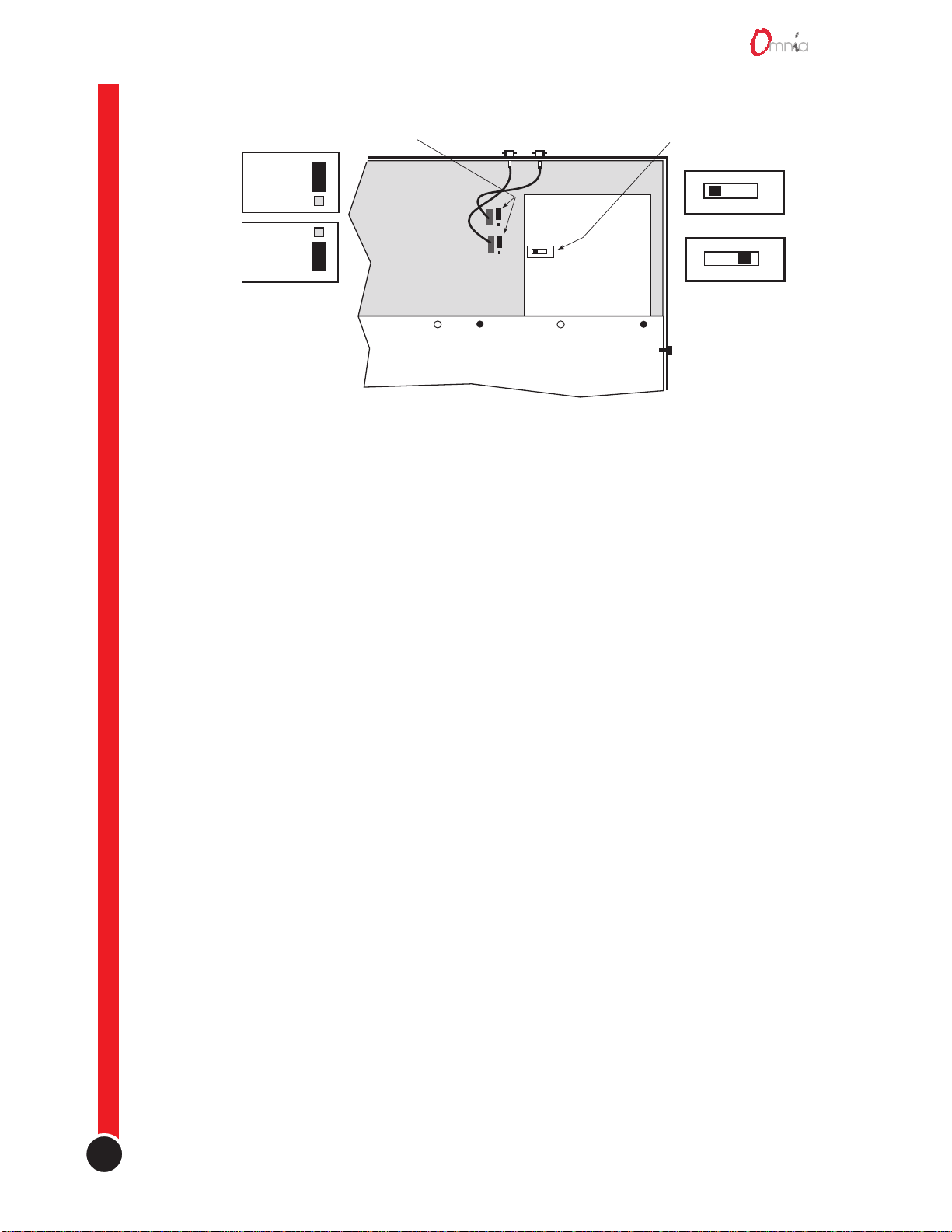
Composite Output Load Jumpers
(for Omnia.fm only)
10 Ω Setting
(Default)
MAIN PC BOARD
75 Ω Setting
IN AGC
DAUGHTER
BOARD
(ADC board)
DSP CARD GUIDE SUBPANEL
Input Overdrive Limiter
On/Off Switch
AGC In (Default)
No Input AGC
Omnia Internal View, Right Rear, Jumper & Switch Locations
Composite Output Series Load (Omnia.fm only)
The default Composite output series load is 10 Ω, which is appropriate for the vast majority of FM exciter
connections. However, exciters manufactured before 1975 need 75 Ω series resistance. Two jumpers on the
motherboard allow the composite outputs to be independently set for either 10 Ω or 75 Ω. The jumpers are
located next to the composite coax cable PC board sockets. The jumpers are set, by default, in the 10 Ω
position. Changing the jumper to the other position changes the series resistance to 75 Ω.
Once all internal changes are finished, reinstall the top cover, making sure all nine Phillips screws are
reinstalled.
AC Environment
Since the Omnia is microcomputer-based, it requires the same clean AC environment as any computer system.
Even though the Omnia has internal AC input transient suppression, we recommend that transient suppressors/
voltage regulation or an Uninterruptible Power Supply (UPS) be employed as well. This is especially
recommended when installing Omnia at a transmitter site. Heavy transient demands on power lines, from
normal switching to lightning strikes, have been known to wreak havoc with data in computer systems. This is
another reason we ask that you give your AC environment thorough consideration before plugging in your
Omnia processor.
1-3
revision 2.0
Page 12
Installation
Omnia Installation & Connections
As these instructions cover the entire Omnia family of processors, there may be some connections listed that are
not used on your specific model. Refer to the individual model chapter for additional details specific to your
Omnia version. Throughout this section reference is made to Omnia’s “software parameters.” These are part of
the User Interface, which is covered in Chapter 2, Omnia Operation.
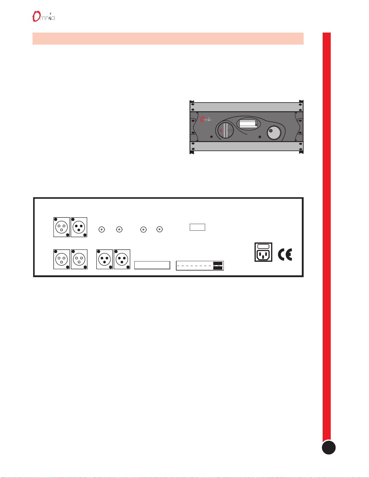
Rack Mounting
The Omnia requires 3RU (5.25") of rack space and four
rack screws for mounting. You must leave at a minimum
one rack unit of empty space above the processor to
enhance ventilation and to prolong component life.
Install a 1RU (1.75") vented or solid panel to fill this
space. It is recommended that another 1RU blank panel
be installed below the processor for the same reason, if
rack space is not at a premium.
AES/EBU
IN OUT
ANALOG INPUTS
LEFT RIGHT LEFT RIGHT
COMPOSITE OUTPUTS
12
ANALOG OUTPUTS
19KHZ OUT
SCA INPUT
RS232
1RU Blank or Vent panel (required)
1RU Blank or Vent panel (recommended)
Omnia 19" Rack Mounting
INTERFACE
EXPANSION CARDS
PROTECT
L
+20
PROTECT
0
IN OUT
-15
-30
R
-40
MEMORY
MODEM
Omnia menu
Audio Processing
Input/Output
Stereo Generator
Go to additional options
UNIVERSAL POWER INPUT
100-240 VAC
1.3-0.3A;50-60HZ
IO
CUTTING EDGE, USA
Omnia Back Panel Connections
AC Connection (IEC)
The Omnia uses a universal power entry module with integral AC switch just above the IEC power cord
receptacle. The Omnia can operate on AC mains voltages from 100 to 240 VAC, 50/60 Hz since a self-adjusting
switching power supply is used. In the USA, plug the supplied AC power cord into the Omnia and then into an
isolated ground AC outlet. Outside of the USA you must obtain an appropriate local IEC power cord.
Press the “I” side of the rear panel power switch to turn on the unit. The Omnia is designed to be turned on
and left on. Press the “O” side of the switch to turn off the Omnia for servicing.
When power is first applied, the Omnia takes ten to fifteen seconds to load the DSP code off the PC Card.
During system power-up, the front panel LCD screen displays several status screens while the operating
software and DSP code is loaded. Once the main Omnia Menu is shown on screen, the Omnia is ready
for use.
1-4
Page 13

Chapter 1
Audio Inputs (Female XLR)
Balanced XLR-type connectors are used to input both analog and AES-3 digital audio. Even though both
analog and digital cables can be connected, only one input can be set active. Input selection is done through the
Input Source software parameter setting. The Analog input is the factory default selection.
The stereo analog inputs are designed for standard +4 dBu balanced signals. The digital AES-3 input accepts
any sampling rate between 32 and 50 kHz. No user adjustment is necessary since a sample rate converter is
built into the unit. Individual channel gain and level setting for both analog and digital is done using the Input
& Output software parameter settings.
A Note About Relative Phase: If the relative phase of your installation including the Omnia differs from your
existing system, it could cause your announcers to feel they sound “weird” in their headphones. If this happens,
then the relative phase of the processor is 180 degrees from what your air talent have been used to hearing. To
remedy this situation, you could reverse the wiring polarity to both of the Omnia’s analog inputs (is pin 2 or
is it pin 3 that's hot!?, in the Omnia, pin 2 is hot). However, it’s a lot easier to accomplish this same function by
changing the Input Phase software parameter setting.
Discrete Audio Outputs—Analog & Digital (Male XLR)
Individual Left and Right analog outputs are available on two male XLR jacks, as is a single stereo AES-3
output. The 48 kHz digital output is produced directly from the output of the final processing section. The
analog output is derived from a D/A converter driven from the digital output.
Note: Both the analog and digital AES-3 outputs are always active and can be used simultaneously.
Composite Outputs (BNC) - For Omnia.fm versions only
These two low impedance outputs (Composite 1 and Composite 2) are each capable of driving up to 50 feet of
coax cable. The output levels are individually adjustable between the outputs so the unit can operate as a
“composite DA” to drive a variety of equipment. The output levels and other stereo generator settings are set
through software parameters.
19 kHz Data Output (BNC) - For Omnia.fm versions only
This TTL-level 19 kHz square wave output can be used as the reference signal for any SCA generator that
operates at 57 kHz or other multiple of the 19 kHz pilot frequency. Using the 19 kHz clock from the Omnia
stereo generator makes it much easier to phase lock the SCA signal to the pilot frequency. This is extremely
helpful in eliminating intermodulation components that might exist between the pilot and SCA signal. For RDS
users, this feature is very useful.
SCA Input (BNC) - For Omnia.fm versions only
Any SCA signal above 53 kHz can be added to the composite outputs of the Omnia by routing the SCA signal
through the SCA INPUT connector. The SCA signal is mixed directly into both composite outputs. A high-pass
filter on the SCA input provides additional crosstalk protection from the SCA to the main channel composite
signal. The SCA modulation is controlled through software parameters.
1-5
RS-232 & Interface Connection (DB-25M and DB-9F)
For a local bidirectional computer connection with the Omnia, connect a standard serial cable (not a null
modem cable) between the RS-232 connector and a serial port connector on the computer. Typically, a DB-25
male to DB-9 female serial cable is required. Communication requires that the Omnia Remote Control software
revision 2.0
Page 14

Installation
be loaded onto the local computer and that the modem port be properly configured for the Windows®
environment.
The Remote Control application is covered in detail in Chapter 9, Accessories.
Interface
The 9-pin female Interface connector uses eight pins as “trigger” inputs with the ninth pin as the ground
reference. The trigger inputs can be used to dynamically alter the Omnia’s operational attributes in response to
logic signal transitions. The Omnia responds uniquely on each trigger input to both go-high and go-low
transitions. With eight inputs, and two possible triggers (logic go-high and go-low), sixteen unique “trigger
scripts” can be written to control the Omnia in response to these trigger input logic transitions.
The Trigger Script Interface Editor is covered in detail in Chapter 9, Accessories.
1-6
Page 15
2
O
M N I A O P E R A T I O N
ith the Omnia rack-mounted, connected to an input and an output, and turned on, it’s about time to
learn how to operate it! This chapter covers the User Interface, the all-important window into the
W
Omnia processor.
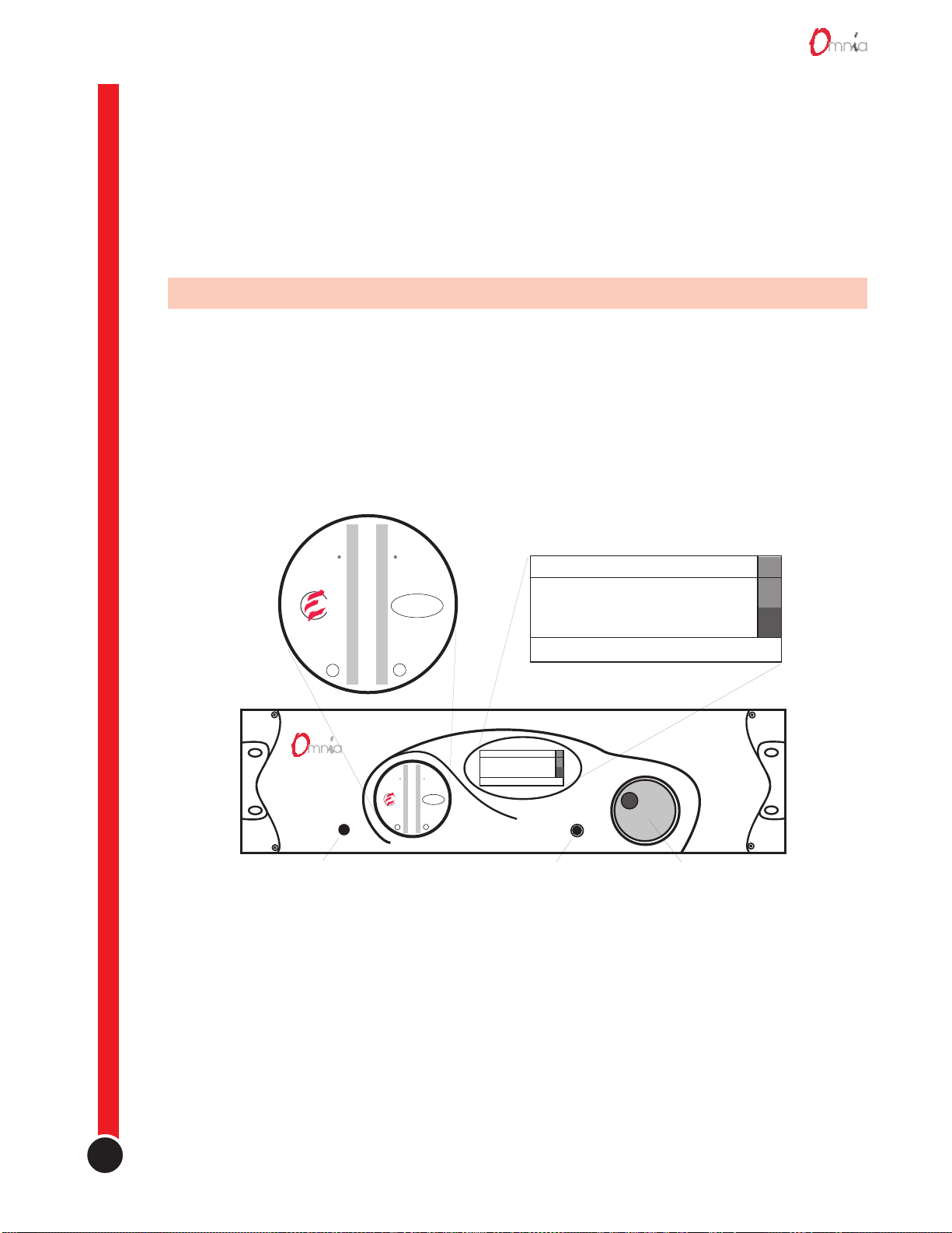
The Omnia User Interface
The Omnia front panel user interface consists of a large jog-wheel, a small recessed push-button, an LCD
screen, two LED meters and a headphone monitor jack.
The LCD screen displays menus, parameter settings, the AGC bargraphs or the Limiter bargraphs. The PushButton toggles between the two types of LCD screen: the menus and the bargraphs. The menus are used during
initial setup and for adjusting the processing parameters. In normal day-to-day operation, one of the bargraphs
is typically displayed to dynamically indicate the real-time signal processing.
PROTECT
Headphone Monitor
(follows In/Out Meter
selection)
+20
0
Input or Output
LED Meters
PROTECT
LCD Screen (showing Start-Up Menu)
Omnia menu
Audio Processing
IN OUT
-15
Input/Output
Stereo Generator
-30
L
R
-40
Omnia menu
+20
PROTECT
PROTECT
0
IN OUT
-15
-30
R
L
-40
(toggles Display between
Audio Processing
Input/Output
Stereo Generator
Go to additional options
Push-Button
menus & bargraphs)
Go to additional options
Jog-Wheel
(selects menu items and
sets parameter values)
Omnia Front Panel Controls & Displays
2-1
The two LED meters display either the audio input or output levels for the Left and Right channels. An IN or
OUT indicator lights to identify the meter source. The headphone monitor audio follows the metering source
selection. The headphone monitor level is set using the Headphones software parameter.
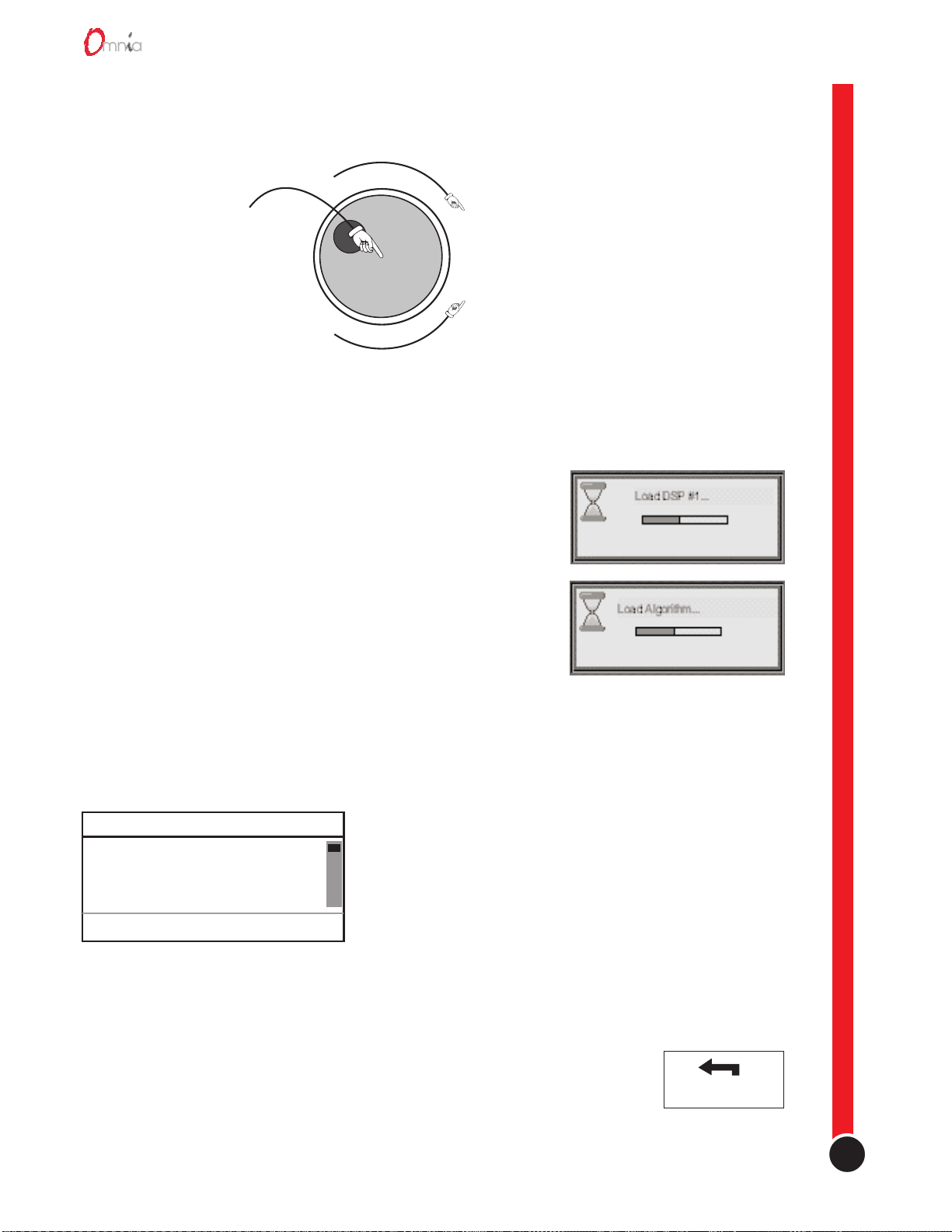
Rotating the Jog-Wheel moves a highlighting bar up or down through menus and parameter choices. Pressing
the jog-wheel (called “clicking”) selects the highlighted menu item or parameter choice. When editing the
parameter values, rotating the jog-wheel adjusts the parameter’s value up (by rotating CW) or down (CCW).
revision 2.0
Page 16
Operation
Once the desired value is reached, clicking the jog-wheel saves the value and returns the display to the previous
menu or sub-menu. Thus pressing or clicking the jog-wheel serves as, depending upon the LCD screen, an
Enter, Select or Return command.
Clockwise rotation moves
the cursor downward in menus
The Enter, Return or
Select button. Pressing
the Jog-Wheel once
selects the highlighted
menu item or accepts
the current parameter
value. Think of it as a
vertical mouse button.
or increases the value when
editing parameters
CW
Counterclockwise rotation
CCW
moves the cursor upward
in menus or decreases the
value when editing parameters
Jog Wheel Use
Main Menu Orientation
When Omnia is first turned on several start-up screens are displayed.
After ten to fifteen seconds the Omnia Main Menu is displayed with
a sliding menu bar along the right side of the screen to indicate your
position within the menu hierarchy. A multipurpose help line is
located at the bottom of the display.
Note: After a time-out, the help line will cycle through: the current
preset name, the status of dayparts, and the day and date. The time is
displayed at the right side.
The Omnia menu system has been designed to be intuitive and simple
to use, with a minimum of sub-menu layers. Most operating
Typical Omnia Startup Screens
parameters are found less than three sub-menus deep. This allows
multiple processing changes to be made “on-the-fly” with relative ease. The complete system is managed
through the four menu choices on the main Omnia Menu. They are: Audio Processing, Input & Output,
Display and Utility. A fifth sub-menu, Stereo Generator, is added for the Omnia.fm and Omnia.fm.jr versions.
Omnia menu
Audio Processing
Input & Output
Stereo Generator
Go to additional options
The Audio Processing menu item is shown highlighted in
the illustration. The highlighting is controlled by the jogwheel. Rotate the jog-wheel CW to step the highlighting
down through the menu items. When the desired menu item
is reached, press the jog-wheel once (“click”) to select that
item. If the item has sub-menus (like Audio Processing),
then the Audio Processing menu choices will be displayed.
Omnia Main Menu Items
If the menu item is a parameter selection, then the
parameter choices or a bargraph value indicator is
displayed. Rotating the jog-wheel steps through the choices and raises (when rotated CW) or lowers (when
rotated CCW) the parameter value. Click the jog-wheel to select the parameter.
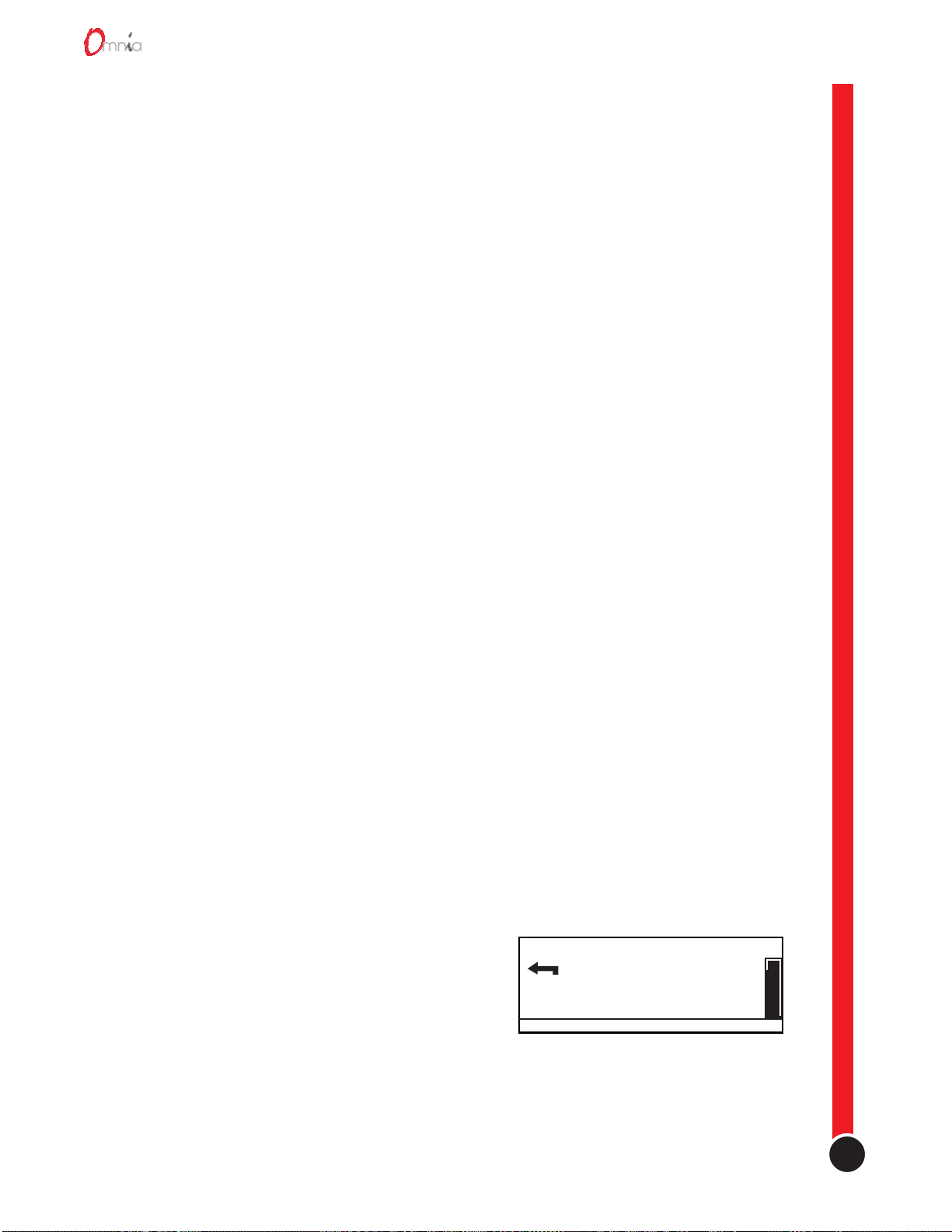
When a sub-menu is displayed, the top menu item will always be the return arrow.
Highlight the return arrow and then “click” to move back to the next higher menu.
Return Arrow
2-2
Page 17

Chapter 2
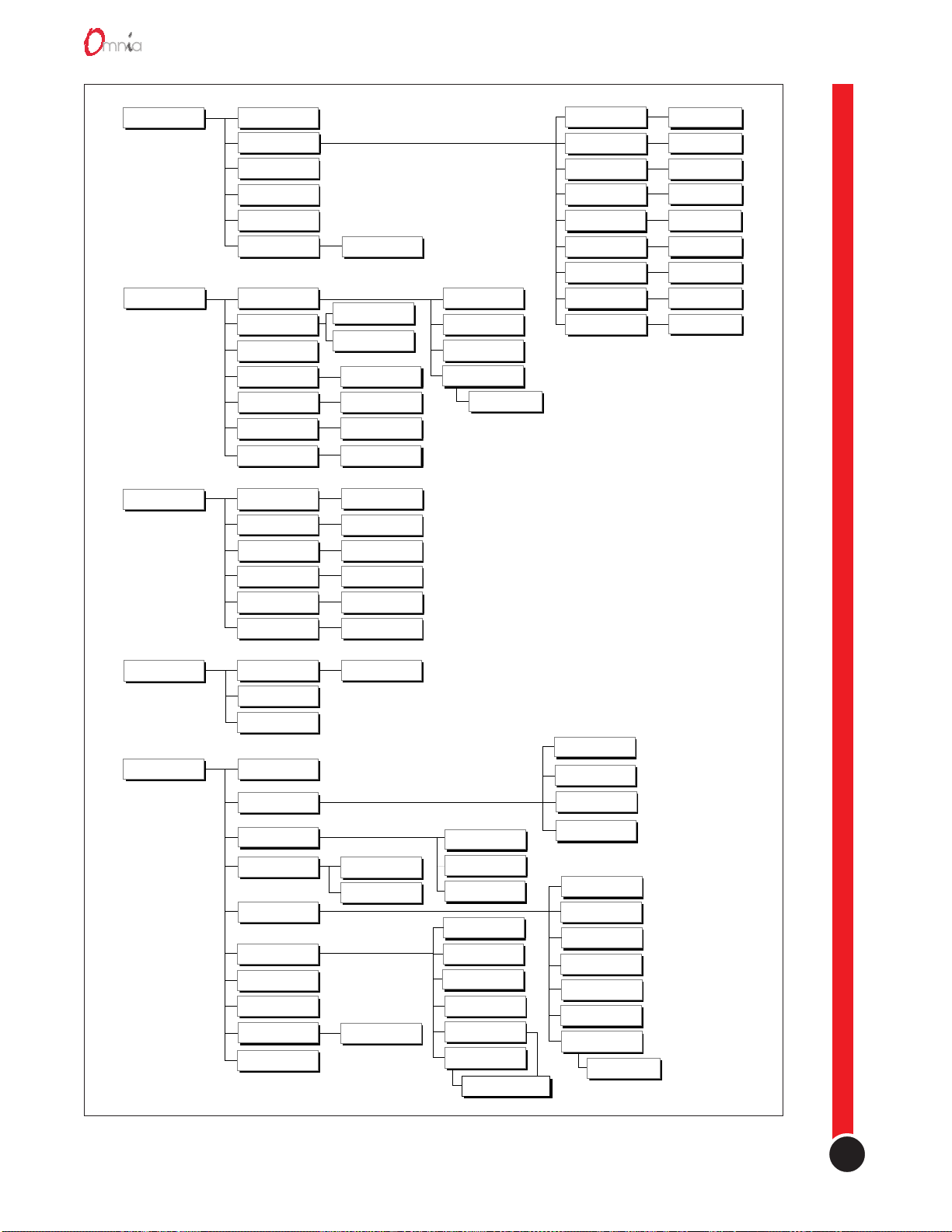
The Menu Tree
The menu tree for the Omnia.fm is shown on the next page (page 2-4). It has all five of the possible main menu
items listed along the left side. The branching sub-menus and parameters connect in the order they are
encountered in the menu system. The Audio Processing sub-menu is the same for all Omnia versions, although
some of the Edit Parameters choices will differ between models. The Input & Output sub-menu is similar
between versions with only Pre-emphasis and De-emphasis not being used in some models (Omnia.am also
adds several choices). The Stereo Generator section is identical between the Omnia.fm and Omnia.fm.jr
versions, but is not used on other versions. The Display and Utility sub-menus are identical in all Omnia
versions.
Note: Each Omnia version has its own chapter that includes a menu tree that is specific to that model Omnia.
Omnia Menu Items
This section gives an overview of the menus, sub-menus and par ameters on the Omnia. Refer to the Omnia.fm
Menu Tree on the following page for the menu structure. The Omnia Software Configuration section, starting
on page 2-8, gives in-depth description and usage instructions on each menu item and parameter selection.
Omnia Main Menu
This menu has four items in Omnia.am, Omnia.net and Omnia.dab: Audio Processing, Input & Output, Display
and Utility. A fifth item: Stereo Generator is added on the Omnia.fm and Omnia.fm.jr versions only.
Audio Processing
It is from the Audio Processing sub-menu items—Select Preset and Edit Parameters, that the Omnia processing
power is unleashed. Omnia is equipped with numerous presets that can be selected to instantly configure the
Omnia processing. The presets are selected using Select Pr eset. Selecting Edit Parameters opens up the
parameter editing sub-menu which allows any processing parameter to be “fine-tuned” to tailor your
processing. Save to Card allows the edited preset to be saved to the PC Card as a new User Preset.
Input & Output
This sub-menu provides level adjustment for the discrete left and right inputs and outputs, selection of analog or
AES-3 input, level control of the front panel headphone output, as well as whether pre-emphasis and deemphasis is applied on the Omnia.fm and Omnia.fm.jr versions. These are generally “set once” selections or
parameters, adjusted during installation and then generally left alone.
Stereo Generator (Omnia.fm and Omnia.fm.jr only)
This sub-menu has the adjustments for the Composite Output Levels, Pilot Level, L-R Gain, SCA Mix Level,
Separation and Pilot Phase.
Display
This sub-menu has the adjustments for the LCD screen (Contrast and Backlight) and the LED metering source
selection (monitor the Input or monitor the Output).
2-3
Utility
Numerous maintenance and utility functions are nested within this sub-menu. Housekeeping of Preset and
System data, along with PC Card maintenance is provided here. Enabling Dayparts as well as setting Security
features to prevent tampering by unauthorized personnel, are also provided under this sub-menu.
(text continues on page 2-5)
revision 2.0
Page 18
Operation
Audio Processing
Input & Output
Stereo Generator
Select Preset
Edit Parameters
Undo Edit
Save to Card
Save to Card As
Editing Mode
Input Levels
Output Levels
Headphones
Input Source
Pre-emphasis
De-emphasis
Mono Mode
SCA Level
Composite 1
Composite 2
Pilot Level
Phase Adjust
Separation
Normal / Expert
Output Left
Output Right
Analog / AES/EBU
None / 50 µs / 75 µs
None / 50 µs / 75 µs
Parameters
Parameters
Parameters
Parameters
Parameters
Parameters
Parameters
Analog Gain
Input Left
Input Right
Input Phase
Normal/Invert
Wideband AGC
Bass
Warmth
Xover
Multiband AGC
Multiband Limiter
Mixer
Clipper
Composite Clipper
Parameters
Parameters
Parameters
Parameters
Parameters
Parameters
Parameters
Parameters
Parameters
Display
Utility
LED Source
Contrast
Backlight
About...
Preset
System Attributes
Card Maintenance
Daypart Table
Security
Set Time
Set Date
Ctrl Port Baud
Reload Software
Input/Output
Copy Entire
Erase User Data
Parameters
Load Defaults
Load from Card
Save to Card
Lock Unit
Login
Lock Password
Engineer Password
Enable Remote
Disable Remote
Select Parameters
Delete
Rename
Copy Single
Copy All
Show All
Add Part
Modify Part
Remove Part
Load from Card
Save to Card
Current State
Enabled / Disabled
Omnia.fm Menu and Submenu Summary
2-4
Page 19

Chapter 2
There is also a selection to save the state of the Omnia operating system. Save to Card makes a “copy” of the
system configuration, storing it on the PC Card. This simplifies getting back to “square one” when numerous
adjustments have been made, but you want to start over. If a power failure should occur, Omnia restarts using
the last saved operational settings. This means all Input & Output settings are restored, as well as the processing
settings. If the system was not backed up and saved to the PC Card, then the system restores itself to the last
known saved set of parameters (which will be the factory defaults if you don’t use Save to Card!). We suggest
you backup the system after any parameter editing is finished.
User Interface Access
The user interface can be password-protected for controlled access. Even for those with access, the parameter
editing functions (Main Menu > Audio Processing > Edit Parameters) can be limited to the Normal Mode (the
default mode). For experienced engineers, individual parameters can be edited using Expert Mode.
Normal Mode, which is the simpler form of operation, is intended for the novice or newcomer to processing
adjustment who may not have an experienced background in audio processing. This level provides just three
adjustable parameters: Thunder, Sizzle and Thrust. As you might guess, these three areas are probably the most
asked about parameters that programmers look to have adjusted. Each control works independently of the
others and can safely be adjusted by nontechnical personnel.
Expert Mode is for the professional who requires detailed control of all processing parameters. Such
parameters as attack/release times, gate thresholds, multiband EQ settings and clipping drive are available at
this level through a graphical block diagram editor interface. CAUTION! This mode could cause an end user to
“crash and burn” if they do not understand the power that is available or the processing concepts involved.
Processing Presets
Omnia is equipped with numerous processing presets, provided as starting points for customizing the sound of
your station and its format. Cutting Edge does not warrant in any way that these presets are the de facto
standards for the format names used. Each was derived in an effort to create a generic starting point for each
respective format. In some markets, these presets may sound too strong or aggressive. In others, they might not
be aggressive enough. Our experiences with the presets in an earlier product, the Unity 2000, were that the
presets were judged to be about 50% good and 50% bad. That feedback indicated to us that we were probably
about in the middle of the playing field with respect to where the presets need to be to serve as a starting point
for any given market.
With all of that having been said, please rely on the presets to get yourself going. From there, we can provide
assistance, if you desire, or you can venture off to discover new frontiers of processed sound. It is our belief that
there is not any nirvana of processed sound, or special secret preset that we keep for only the Big Stations.
Each station in each market is unique unto itself. Try to remember that when “crafting” that special sonic
personality for your station. Omnia gives you the power to create a sound totally different from, and better than,
your competitors. Enjoy that power!
2-5
We could publish the entire preset list, but chances are that we will continue to develop new or modify existing
presets. So, a list that is guaranteed to be obsolete would be of little help. Besides, the name of each should be
self-explanatory. If you need more clarification, please contact the technical support department.
revision 2.0
Page 20
Operation
Format Presets
Each Omnia comes with processing presets designed for that model Omnia that cover most broadcasting
formats or netcasting applications. Some models have only a handful, whereas Omnia.am includes 27 presets
(plus a test tone!). A preset contains the saved values for every parameter listed in the menu tree for that model.
When a preset is loaded, these values configure the Omnia’s processing.
The factory presets can be used as-is, or they can be used simply as a starting point to tailor the processing for a
specific requirement. Any of the preset’s parameters can be edited (using Main Menu > Audio Processing > Edit
Parameters) to obtain the desired sound using either the Normal or Expert editing modes. The edited preset can
then be saved to the PC Card as a User Preset and selected just like the factory presets. Editing presets is
covered in detail in Chapter 8, Editing Presets. This section covers how to select and load a preset.
Selecting A Preset
From the Main Menu, highlight and click Audio Processing. Then highlight and click Select Preset. The name
of the preset that is currently running is displayed. Use the jog-wheel to scroll through the list to find a preset to
load. Once the desired preset name is displayed, click the jog-wheel to immediately load that preset into the
Omnia. This also returns you to the Select Preset menu item.
Note that once you move the jog-wheel to display another preset name, a message below the preset name
indicates the previous selection, i.e., “(was Jazz-6AM)” will be shown if that was the currently running preset.
This serves as a reminder, so you can reselect that preset in case you change your mind about changing presets,
since there is no way to “cancel” selecting a new preset to load.
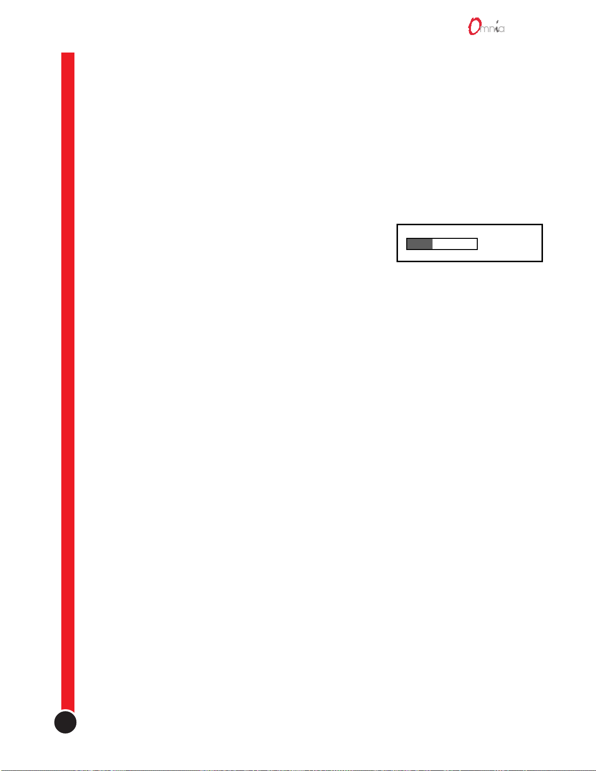
A thermometer bar along the left side of the window indicates where you are in the list of presets. All User
Presets are added onto the end of the list, so they will be found when the bar is toward the bottom of the
thermometer.
Daypart Automation
Presets can be scheduled in advance to automatically load based upon specific daypart requirements.
Dayparting can be set to occur on specific days, on a daily basis, on weekdays-only or on weekends-only. The
daypart schedule and settings can also be saved to the PC Card.
Even though dayparting can be configured using the Omnia menus, it is far easier to set up and adjust the
dayparting using the Daypart Table Editor included with the Omnia Remote Control application. See Daypart
Editor in Chapter 10, Accessories, for more information on using this editor.
Input Source Selection & Analog Input Gain Adjustment
The following two exercises are a useful introduction to the Omnia user interface. Start from the top of the
Main Menu (as displayed when the unit is first turned on). The first exercise chooses a parameter selection:
1.Rotate the jog-wheel to highlight Input & Output.
2.Select this menu item by “clicking” the jog-wheel (push
once on the jog-wheel). The Input & Output sub-menu is
presented.
3.Rotate the jog-wheel CW to scroll down to highlight Input
Source.
Input & Output
Input Levels
Output Levels
GO TO ADDITIONAL OPTIONS
Input & Output Sub-Menu
10:10AM
4.Click the jog-wheel to select Input Source. An expanded edit box appears with the word ANALOG
shown in large type (this is the default input selection).
2-6
Page 21
5. Rotate the jog-wheel to alternate between the available parameter choices, in this case: ANALOG and
Edit Analog Gain setting
5.5dB
(was 0.0)
0.0 12.0
AES/EBU. Note that the choices do not “wrap around.” You must rotate the jog-wheel CCW to return to
a previous choice.
6. With ANALOG displayed, click the jog-wheel. The selection takes effect and the screen returns to the
sub-menu item (Input Source).
The next exercise adjusts a parameter that uses a value:
1. From the Input & Output sub-menu, rotate the jog-wheel until Input Levels is highlighted.
2. Click the jog-wheel to select and display the Input Levels sub-menu.
3. The highlighted item is the Analog Gain parameter. Click to select.
4. An expanded edit box appears at the bottom of the display with
a level bar displayed in the middle. Rotate the jog-wheel CW to
increase the input gain in 0.5 dB steps. Rotate the jog-wheel
CCW to decrease the input gain in 0.5 dB steps. The current
setting display “5.5 dB” updates as the jog-wheel is moved.
Just below the current setting is the previous setting display
“was 0.0.” All parameters display the previous setting below the current setting as soon as the jog-wheel
is rotated. This allows the parameter to be easily returned to its previous setting.
Analog Gain Parameter Display
Chapter 2
The Analog Gain parameter sets the gain for both channels. Normally, this adjustment is made while
monitoring the input LED meters. Peak indications hitting 0 dB (where the LEDs turn red) or a little
higher, is proper. This corresponds to a system headroom of about 18 dB. If further gain or attenuation is
required, the individual left/right channels can be adjusting using the Input Left and Input Right
parameters (which are the next menu items below Analog Gain).
5. Once the desired gain is reached, click the jog-wheel to accept and use the value and to return to the submenu item (Analog Gain).
All of the Omnia’s software parameters are set in similar fashion through scrolling through menus and submenus to select which parameter to edit. The parameter choices or values are then selected by rotating the jogwheel until the desired setting is displayed. Clicking the jog-wheel selects the parameter value and returns to the
menu or sub-menu item.
Note: Changing the parameter value or choice changes the audio output so that changes can be auditioned in
real time.
The next chapter (Chapter 3, Processing Overview) presents an overview of the Omnia processing. Chapter 8,
Editing Presets, gives more information on editing parameters including procedures for editing the factory
presets to create your own custom presets.
2-7
revision 2.0
Page 22

Operation
Omnia Menu Selections
This section presents more detailed information on each menu and sub-menu item and their parameter choices
or value settings. This procedure is used for all parameter selection and editing:
1.Use the jog-wheel to highlight a menu item or sub-menu item.
2.Click the jog-wheel to open up that item.
3.Once a parameter is displayed, highlight and click the name to open up the parameter value edit box.
4.Use the jog-wheel to adjust the value or change the parameter choice.
5.Click to accept the value and return to the sub-menu.
Audio Processing
This sub-menu has six items: Select Preset, Edit Parameters, Undo Edit, Save to Card, Save to Card As and
Editing Mode.
Select Preset
Opens up a selection box to select a factory preset or a user preset that was previously saved to the PC Card.
Edit Parameters
What happens when this menu item is selected is dependent upon the Editing Mode selection (either Normal or
Expert). Regardless of which editing mode is used, an editing change made in one mode is reflected in the other
mode’s parameter value settings. Normal mode allows nontechnical personnel to make processing changes
without having to understand details about AGC levels, attack and release times, etc.
Editing Parameters in Normal Mode
To make it easy to obtain the desired sound, only three general parameters are available: Thunder, Sizzle and
Thrust. As might be surmised from the names, Thunder deals with the bottom end bass sound, Sizzle sets the
high end sound and Thrust adjusts the voice-range or presence sound. Changing one of these three parameters is
equivalent to individually selecting (and changing) multiple Expert Mode parameter settings. For instance,
changing the Thunder setting affects the levels of the Deep, Phat and Warm Bass settings simultaneously.
Likewise, individually changing the Deep, Phat or Warm Bass settings in Expert Mode will affect the Thunder
level displayed when the editing mode is changed to Normal Mode.
Editing Parameters in Expert Mode
This is a very different editing experience than that found in Normal mode. Expert Mode opens up a processing
block diagram on the LCD screen. The first block’s name “AGC Wideband” flashes, indicating that it’s the
current parameter. To edit the AGC Wideband parameters, click the jog-wheel. A list of the parameters relevant
to that part of the processing algorithm is shown (in this case; Phase Rotator, Wideband AGC, etc.). To edit
another block’s parameters, rotate the jog-wheel until the desired block name is flashing and then click the jogwheel. Expert Mode editing is covered in more detail in Chapter 8, Editing Presets.
Undo Edit
Restores the last edit operation.
Save to Card
Saves the current parameters to the PC Card, overwriting any previous settings saved under the current Preset
name. This function cannot be used with factory presets, since they cannot be changed. If a factory preset is
changed, and the changes should be saved, use Save to Card As to save the changes under a new name.
2-8
Page 23

Chapter 2
Save to Card As
Opens up a Preset Naming dialog box to allow the Preset name to be changed before saving the preset to the PC
Card. Preset names can be up to 20 characters in length. All of the standard (non-extended) ASCII characters
are valid. Click the jog-wheel to select a highlighted character to change. Then rotate the jog-wheel to step
through all the possible characters. Once the desired character is displayed, click the jog-wheel to select that
character. The highlighting moves to the next character. When the last character is reached, rotate the jog-wheel
to highlight Save. Click to save the preset. Highlight Cancel to cancel the Save to Card As operation.
Editing Mode
Selects between Normal and Expert Edit Modes. The factory default is Normal Mode. This selection can be
password protected to prevent changes.
Input & Output
This sub-menu has five main items: Input Levels, Output Levels, Headphones, Input Source, Mono Mode, plus
two additional items (Pre-Emphasis and De-Emphasis) in the Omnia.fm / .fm.jr models and four additional
items (Asym Mode, Tilt EQ, Tilt Frequency and HP Filter) in the Omnia.am model.
Input Levels
Four parameters are under this sub-menu item: Analog Gain, Input Left, Input Right and Input Phase
Analog Gain
Active only when the analog inputs are used and when input AGC is active (the default setting). This parameter
sets the input operating reference level between -15 dBu and +4 dBu. The factory default setting is +4 dBu. To
change input sensitivity, use the jog-wheel to adjust the level in 0.5 dB steps, with 0 dB having the least amount
of gain and 12 dB having the maximum gain. Use the LED meters (set for Input Monitor) to make this
adjustment so that signal peaks read at 0 dB or a little higher. Peaks at 0 dB correspond to -18 dBFS (decibels
below Full Scale digital, i.e. the digital clip point) or headroom of 18 dB. If further gain or attenuation is
required, or if the signal levels are not balanced between channels, the Input Left and Input Right parameters
can be adjusted to compensate.
Note: The Analog Gain parameter is not active when the AGC analog input limiter is defeated (refer to the
Input switch & Jumper section on page 1-2). In this condition, the input sensitivity is fixed at +4 dBu.
Input Left and Input Right (Digital Input Level)
These level controls are active when either Analog input or AES/EBU input is selected since their adjustments
take place in the digital domain. The factory default setting is +4 dBu. To change input level, rotate the jogwheel to adjust the level in 0.5 dB steps. Use the LED meters (set for Input Monitor) to make this adjustment so
that signal peaks read at 0 dB or a little higher. Peaks at 0 dB correspond to -18 dBFS (decibels below Full
Scale digital, i.e. the digital clip point) or headroom of 18 dB. These are the only level controls for the AES/
EBU input. For analog inputs they work in conjunction with the Analog Gain parameter and are typically used
to fine-tune the balance between the channels.
Input Phase
If the relative phase relationship of the Omnia is different from your existing system, a backup system, or the
system you may be comparing it to, it could cause your announcers to think they sound “weird” when
monitoring through the system using their headphones. If this happens, the relative phase of the Omnia is 180
degrees different from what your announcers are used to. To remedy this, you can reverse the polarity with this
menu selection.
2-9
revision 2.0
Page 24

Operation
Output Levels (Digital Output Level)
Adjustment of the left/right audio levels is done in the same manner as setting the input levels, except that the
LED meters would be set for Output Monitoring. Since these settings take place before the D/A converter, the
settings affect both digital (AES/EBU) and analog outputs.
Note: Both the analog and digital AES/EBU outputs are active at the same time. Connections can be made
simultaneously to the analog and digital outputs, as well as the composite outputs on the Omnia.fm & .fm.jr.
Headphones
The front panel headphone output is active at all times and its audio signal is always flat (its de-emphasis
automatically follows the Pre-Emphasis choice on Omnia.fm & .fm.jr). This parameter adjusts the output level
for the front panel headphone jack only.
Note: The Output Levels parameter should be set before setting the Headphones level, since it affects the
headphone levels when switched for output monitoring.
Input Source
Selects whether the input is supplied by the Analog or Digital input.
Mono Mode
Selects between stereo and mono. When mono is selected, allows the left channel, right channel, or a sum of the
two input channels, to feed both left and right outputs with a mono signal.
Pre-Emphasis (for Omnia.fm and Omnia.fm.jr only)
For FM broadcasting worldwide, some form of time constant pre-emphasis, typically 50 µs or 75 µs, is
employed. For North and South America, 75 µs is used. In Europe, Australia and New Zealand, 50 µs is
employed. The factory default pre-emphasis setting is 75 µs. The pre-emphasis selection affects the operation of
the audio processing and is applied to both the composite and discrete outputs. The pre-emphasized signal at the
Left/Right outputs can be restored to flat, if needed, by the De-Emphasis parameter selection.
To set the Pre-Emphasis, rotate the jog-wheel to cycle through the three choices: None, 50 µs or 75 µs. Click the
jog-wheel to set the pre-emphasis selection.
Note: Normally, the None selection would not be used in FM transmission applications, but is provided in
instances where processing of a flat signal is desired. One example would be when preprocessing prior to a
satellite uplink in distributed radio networks.
De-Emphasis (for Omnia.fm and Omnia.fm.jr only)
The Left/Right outputs are pre-emphasized under normal circumstances, such as when feeding an outboard
stereo generator or discrete microwave studio-transmitter link. The same applies when feeding a digital exciter
from the AES/EBU output. These outputs can also be de-emphasized for installations that require a flat
response, as is the case when feeding land lines. The factory default de-emphasis setting is 75 µs.
To change the De-Emphasis setting, rotate the jog-wheel to cycle through the three choices: None, 50 µs or 75
µs. Click the jog-wheel to set the de-emphasis selection. If choosing a de-emphasis time constant, be sure it
matches the pre-emphasis time constant. Bear in mind that selecting None means that the outputs have preemphasis, assuming that one of the time constants was selected in Pre-Emphasis.
Note: The De-Emphasis setting does not affect the composite output, which always follows the Pre-Emphasis
setting.
Asymmetrical Modulation (Omnia.am only)
Asymmetrical positive modulation is possible by adjusting this parameter. The range of adjustment is between
+100% and +150% modulation.
2-10
Page 25

Chapter 2
Tilt EQ (Omnia.am only)
Sets the amount of tilt compensation in the Omnia.am’s output. To perform the procedure, an oscillator and
oscilloscope will be required. See Chapter 5, Omnia.am for details.
Tilt Frequency (Omnia.am only)
Sets the frequency where tilt compensation starts. See Chapter 5, Omnia.am for details.
LP Filter (Omnia.am only)
Sets the frequency of the low pass filter used at the output of the Omnia.am. See Chapter 5, Omnia.am for
details.
Stereo Generator (Omnia.fm and Omnia.fm.jr only)
Six parameters are set under this sub-menu: SCA Level, Composite 1, Composite 2, Pilot Level, Phase Adjust,
and Separation. See Chapter 4, Omnia.fm for more information on the settings in this sub-menu.
Display
Three parameters are set under this sub-menu: LED Source, Contrast and Backlight.
LED Source
Sets the source for the LED meters on the Omnia’s front panel between Omnia’s Input and its Output. The
headphones follow this selection.
Contrast
Adjusts the brightness difference between the lightest and darkest segments in the front panel display. Note that
if this setting is mis-adjusted the display will “disappear.”
Backlight
Adjusts the LCD’s backlight to compensate for room brightness.
Housekeeping
An important activity after any Preset editing session or system parameter adjustment is to always save these
changes to the Omnia PC Card. It is also a good idea to occasionally backup your Omnia PC Card to another
PC Card for safe keeping away from the system. These activities are done using the Utility menu. There are
various system options available—ranging from copying the PC Card to restoring basic operational default
parameters. To access these functions, select the Utility menu. Scroll down and select System Attributes.
The Utility Menu
There are nine parameters or sub-menus reached through this menu item: About. . ., Preset, System Attributes,
Card Maintenance, Daypart Table, Security, Set Time, Set Date and Reload Software.
About
This parameter displays various screens describing the software revisions that are currently being used.
2-11
Preset
This sub-menu has four parameters: Delete, Rename, Copy Single or Copy All. The first three function on a
single User Preset. Select Delete to permanently delete a User Preset from the PC Card. Select Rename to
change the name of an existing User Preset. Select Copy Single to copy one of the User Presets to another PC
Card. Select Copy All to select all user Presets to copy to another PC Card.
revision 2.0
Page 26

Operation
System Attributes
There are three parameters under this sub-menu item: Load Defaults, Load From Card and Save to Card.
Load Defaults
Reloads all of the default parameters into the system. This is the same as a warm boot command on a computer.
All Input & Output levels are reset to the factory default settings.
Load From Card
Allows processing settings to be loaded into the system from a different PC Card. When selected, follow the
instructions presented on the LCD screen to perform this function.
Save To Card
Creates a backup of the system software and writes it to the PC Card. This is a good safety practice that will
create a backup of data that is also stored in the nonvolatile RAM within the Omnia. Think of this as a PC Card
backup to what is stored internally. When selected, a naming dialog box appears.
Card Maintenance
From the Utility sub-menu, the Card Maintenance sub-menu gives access to PC Card maintenance. Two
choices are provided:
Copy Entire
Allows the user to make a duplicate of the PC Card which could be used in a different Omnia processor.
Caution: It should restated here that when making a copy of the PC Card, spares must be obtained from
Cutting Edge. Failure to do so may result in damage to the unit, which will void the warranty.
Erase User Data
Choose this selection when you want to erase all user information on the PC Card. When this function is
selected, the PC Card is restored to the initial default settings, and only the factory presets are available. This
restores the card to a condition when first delivered from the factory. Before this function is implemented, a
pop-up screen will ask for confirmation before actually erasing the card. Follow the instructions presented on
the screen to carry out this function.
Daypart Table
The audio processing in the Omnia can be automatically adjusted by dayparts. This permits different presets to
be invoked according to a schedule that you create. The start day can be any specific day of the week, weekdays
(M-F), weekends (S-S), or every day (All). Dayparts must end within a 24 hour period. Over 450 individual
events can be programmed within a 7-day interval. Sub-menus allow viewing and setup of dayparts. These submenus include:
Show All
Displays all of the currently defined dayparts through a series of dialog boxes.
Add Part
Permits the creation of dayparts. Using various screens, you can select the start day and time, the end time, and
preset.
Note: If there is no daypart selected for an interval of time, the system defaults to the preset selected by the user
before dayparting is enabled.
Note: You can cancel the Add Part operation at any time by selecting the Cancel option on any of the daypart
Add Part screens. The system will warn the user if the daypart being added overlaps one of the dayparts already
defined.
2-12
Page 27

Chapter 2
Modify Part
Permits editing of dayparts already created. The system prompts the user to select one of the currently defined
dayparts, and then displays the same sequence that the user would see when doing an Add Part, allowing you to
edit the daypart. The user can then change the start day and time, end time, or preset associated with the daypart
being edited.
Remove Part
Permits removal of a daypart. The system prompts the user to select one of the currently defined dayparts, and
then prompts the user with a Continue To Delete? dialog with a Yes/No option. If the user selects Yes, the
selected daypart is deleted.
Load from Card
Retrieves daypart data stored on the PCMCIA card. This operation will restore any dayparts that were
previously saved to the card with the Save to Card operation, described below.
Save to Card
Backs up daypart information onto the PCMCIA card (for safety and sharing with others). It saves all of the
currently defined dayparts and the daypart state to the Omnia PC card. These settings can be loaded later by
selecting the Load from Card option.
Current State [Enabled/Disabled]
Activates or deactivates the use of created dayparts. If Enabled, then the system will automatically change
presets as specified by any of the dayparts defined. If Disabled, then the system will not use any of the dayparts
defined.
Security
Security permits “lockout” of the unit to prevent unauthorized personnel from making adjustments to the
Omnia. Normal mode allows read-only access to the Omnia and its menu structures. Engineer mode allows
full access to control of the unit. Sub-menus include:
Lock Unit
Immediately locks the unit. A dialog box is presented for password entry to unlock the unit.
Log-in
Permits access at one of two security levels (Normal or Engineer), using the appropriate password. Normal
mode allows read-only access to the Omnia and its menu structures. An Engineer mode allows full access to
control of the unit. Default passwords supplied with the unit are:
Normal mode: vito (all lower case)
Engineer mode: tomtom (all lower case)
Note: You can only Log-in at the same access level at which the unit was locked. In other words, if you locked
the unit while in the Engineer mode, you must supply the Engineer password. If you locked the unit in the
Normal mode, either the Normal or Engineer passwords will unlock the unit.
Caution: Do not attempt to assign the same password to both security levels! You will lock yourself out
permanently!
To change a password, use the standard click and turn of the jog-wheel to select the character position you wish
to change, and to select the character for that position.
2-13
After choosing a new password, continue rotating the jog-wheel until OK is highlighted. Push on the jog-wheel.
The password is now saved. If you wish to cancel this operation, just scroll onto the Cancel box and press the
jog-wheel. The operation is canceled.
revision 2.0
Page 28

Operation
Lock Password
Allows changing the name of the password for “Normal” access. Can be performed either from “Normal” or
“Engineer” security levels.
Engineer Password
Allows changing the name of the password for “Engineer” access. Can be performed either only from the
“Engineer” security level.
Enable Remote
Allows remote control access to individual system parameters previously inhibited by the Disable Remote
command (see below). In other words, you can selectively cancel individual parameters that were disabled for
remote access. A list of parameters that have been disabled, through the Disable Remote menu, to remote users
is displayed. When a parameter is selected, it becomes available to “Engineer” password users to edit through
the remote software. Selecting None exits the Enable Remote screen without changing the current settings.
Disable Remote
Allows the user to restrict access to a list of system parameters so that remote users won’t be able to change the
selected parameters. When the Disable Remote option is selected, a list of the system parameters that are
editable through the remote is displayed. When a parameter is selected, it is no longer editable through the
remote command interpreter. Selecting None exits the Disable Remote screen without disabling any
parameters. To restore a parameter so that it can be edited by remote users, use the Enable Remote option.
Set Time
Sets the current time for the unit, which needs to be performed before dayparts can be used. The time is set
using the familiar “turn and push” action of the jog wheel.
Note: The time can be synchronized to “:00” seconds by pressing the jog wheel in synchronization with the
seconds indicator of an external clock. To maintain accurate dayparting, periodically reset the internal clock to
your external reference.
Note: An additional menu will prompt you to set the unit to Daylight Saving or Standard time.
Set Date
Sets the current date, which needs to be performed before dayparts can be used. The date is set using the
familiar “turn and push” action of the jog wheel.
Control Port Baud
This option sets the communications port communications parameters.
Reload Software
This option loads the operating software from the PC Card into the Omnia memory.
Bargraph Display Screens
Two bargraph screens are available on the Omnia.fm and Omnia.dab models: one for the AGC activity and a
second for the Limiter activity. The Omnia.fm.jr, Omnia.am, Omnia.net models have only one combined
“Process” bargraph screen showing the WideBand AGC bargraph and either three or four limiter bargraphs.
The bargraph screens are displayed by pressing the front panel push-button. This changes the LCD from
showing menus to displaying the AGC screen (or the single Proc bargraph display in some models). Rotate the
jog-wheel clockwise to display the Limiter activity bargraphs. Rotate the jog-wheel counterclockwise to return
to the AGC activity bargraphs.
2-14
Page 29
Chapter 2
0dB
-10dB
-20dB
AGC
WIDE LOW MID PRES HIGH
0dB
-10dB
-20dB
LIM
LOW MID PRES HIGH
0dB
-10dB
-20dB
PROCESS
WIDE LOW MID HIGH
AGC Display
The mode of operation for the AGC section is
basically the same for both the WideBand AGC and
the multiband AGCs. Each AGC section has an
individual GATED indicator that operates as
determined by the individual Gate setting for that
particular band. The bargraphs are capable of
indicating up to 25 dB of gain reduction on a linear
scale.
Note: The only operating difference between the wideband and multiband AGCs is that the wideband AGC will
“recover” to a platform of 10 dB of gain reduction if it is gated over a long period of time. If gating occurs in
the multiband section, recovery behavior will depend on the Return to Platform (RTP) settings employed (see
Chapter 8, Editing Presets, for an explanation of RTP).
Omnia AGC Activity Bar gr aph Display
Limiter Display
The Limiter bargraphs provide a wealth of
information about Omnia’s peak control. The
limiter algorithms have the ability to modify the
style of peak control that is employed on a moment
by moment basis. This can be seen if observed over
a period of time, say a few minutes. During normal
operation, the limiter indicators will have a
dynamic “bounce” that you will be able to get a feel
for. But every now and then, the limiter will very quickly show a large amount of gain reduction. Notice that the
response is very fast. To accommodate this indication, Omnia provides an additional indicator bar that shows
the most recent indication of large scale gain control. This action will recover very slowly, and return to “rest”
with the main bargraph. This action will be easily noticed on material that is very dynamic in texture.
Omnia Limiter Activity Barg raph Display
Another feature of the limiters, which is not indicated by a separate indicator, is the limiter “Hold” function.
During brief pauses in limiter activity the bargraphs will “freeze” to show that the limiter has entered the Hold
function of the algorithm; this is akin to the GATE function in the AGCs. This will be easily noticed whenever
there is a “dry” voice being processed. The Limiter bargraphs, like the AGC section, can indicate up to 25 dB of
gain reduction.
Process Display
The wideband AGC section has an individual
GATED bargraph that operates as determined by
the Gate setting for that band. The bargraph is
capable of indicating up to 25 dB of gain
reduction.
Note: It is normal for the wideband AGC to
“recover” to a platform of 10 dB of gain
reduction if it is gated over a long period of time.
Refer to page 8-3 (Editing Presets chapter) for more information on interpreting and using the various bargraph
displays.
2-15
Omnia.fm.jr, Omnia.am and Omnia.net
Single Bargraph Display
revision 2.0
Page 30

This page left blank intentionally.
Page 31

3
P
R O C E S S I N G O V E R V I E W
his section presents an overview of the Omnia processor using the block diagram from the Omnia.fm to
provide a functional order to the various processing sections. Not all processing sections discussed in
T
this section are found in each Omnia model. Refer to the chapter on your Omnia model for additional
processing information including a version-specific block diagram and a menu tree. Parameter Worksheets for
each model Omnia can be found in Appendix B.
Note: More detailed technical information about the audio processing employed in Omnia can be found in the
Technical Papers section on the Omnia web site (www.omniaaudio.com).
The Omnia and Audio Processing
Omnia consists of nine general processing sections that are used in most versions. These include an input AGC
circuit for initial level control, bass and warmth EQ adjustment sections, a multiband AGC and limiter, a mixer
circuit and a limiter or compressor at the output. The block diagram presents these processing blocks as used in
the Omnia.fm.
WideBand
AGC
Bass
Warmth
X-
Over
Hi
AGC
Pres
AGC
Mid
AGC
Lo
AGC
Hi
Limiter
Pres
Limiter
Mid
Limiter
Lo
Limiter
Mixer
Clipp
er
Composite
er
Clipp
Stereo
Generator
Left
Output
Right
Output
Omnia.fm Block Diagram
Wideband AGC: A very flexible wideband leveler section to provide transparent and smooth control of the
input program. This is achieved through two significant innovations: a dual referenced gate and an intelligent
“makeup” gain algorithm. The dual gate reference is a unique process that references the input dynamics to a
“rolling” reference level.
A user-adjustable Make-Up Gain feature uses an algorithm incorporating a hidden control signal that knows
when a sustained softer portion of program is occurring. It then “fills in” the softer section so that the average
level is increased. This allows the overall AGC function to operate with a slower time constant, yielding lower
intermodulation distortion without losing loudness in the softer passages.
3-1
As an example, with classical music, the orchestra might be playing along at a fairly robust level, then enter into
a quiet passage. A conventional AGC would hold the softer passage down until it was able to slowly recover,
keeping the soft passage much too quiet! With Omnia’s new makeup gain function, the hidden, faster time
constant will allow a quick recovery, but only during the softer passage. As soon as the orchestra starts to play
louder, the “makeup” time constant yields control to the primary AGC circuit, hence returning gain to the
previous platform level. This sophistication better preserves the dynamic integrity of the signal.
revision 2.0
Page 32

Processing Overview
A built-in phase rotator ensures symmetrical clipping of positive and negative peaks. But, for a more musically
transparent sound, this feature can be defeated. As can the entire Wideband AGC section to facilitate the use of
external AGCs.
Bass EQ: For those who demand thunderous bass, the Omnia’s got it! Up to 12 dB of “thunder” can be added to
shake your listener’s walls! This is not some simple bass EQ, but rather a sophisticated concept that takes into
consideration the time alignment of the low frequencies as they pass through the entire system. This allows
loud, clean low end, with no sacrifice to the overall loudness of your signal. The Deep Bass and Phat Bass
parameters are found under the Bass menu in most Omnias. Deep Bass is a shelf boost at 90 Hz that utilizes a
phase linear 12 dB/octave slope to produce the shelving EQ function. Phat Bass is a unique enhancement that
adds filtered harmonics to the bass frequencies. Low frequency texture is emphasized with this parameter. Older
materials sound fuller (or phatter) with the added illusion of loudness.
Warmth EQ: The Warm Bass parameter is found under the Warmth menu in most Omnias. Warm Bass is a shelf
boost that functions up to 150 Hz. Adjusting Warm Bass compensates for program material that is naturally
lacking in upper-bass punch. The parameter is adjustable over a 6 dB range.
Phase Linear, Time Aligned Crossover: This network is time aligned to keep the full audio spectrum exactly
synchronized through the entire system. This reduces the chance for any phase errors to occur at the crossover
frequencies when the audio bands are summed back together after dynamic processing. The crossover is phase
linear in design. The result: a truer, more natural sound. Four bands are used in Omnia.fm (and most other
versions as well) but only three bands are used in the Omnia.fm.jr and in the Omnia.fm.jr presets found on the
Omnia.fm.
Most multiband audio processors must make a compromise in the crossover area: either provide true phase
linearity, or dynamic flat response. The problem with implementing only the former is that, under dynamically
controlled conditions, peaks or notches will occur at the crossover frequencies once the bands are recombined.
In an effort to minimize this problem in older designs, crossover frequencies were phase-offset, so when they
were recombined, these peaks and notches would be minimal—thus maintaining some degree of flatness. Such
a compromise results in the loss of phase linearity, which reduces clarity. In Omnia’s DSP implementation, the
crossover network is carefully time-aligned so the recombined spectrum remains flat, regardless of the amount
of gain control being applied within any band. This yields a phase linear response, so that no harmonic content
is ever displaced in time. The result: a truer, more natural sound.
Multiband AGC (not used in Omnia.fm.jr): This section uses the same algorithm as described above in the
Wideband AGC, except that it is spread over four independently operating bands. The control functions for each
band have been optimized for that range of frequencies. The only significant difference between the Wideband
and Multiband AGCs is that, in the latter case, additional controls, like adjustable recovery speed, are provided
to establish how each band “recovers” when gated. Recovery can also be defeated so that the gain will “freeze”
when gating occurs.
This Multiband AGC has numerous capabilities that were impossible to perform in the analog domain—precise
RMS calculation, for example. Analog RMS is calculated using a simple RC time constant operating in the log
domain. Since analog exponential circuits are prone to drift, they are usually kept very simple. This RC time
constant is used to calculate the average level of the audio (its RMS value). This is suitable when measuring a
single frequency, or a very narrow range of frequencies, but with an audio processor, we need to perform this
function with music. Even within the framework of a multiband processor, the single time constant can produce
inconsistent results under various dynamic conditions. Here is where DSP comes in handy. Using a newly
developed algorithm for RMS calculation, the DSP will calculate the average level as a rolling average. This
will adapt the averaging to changes in the dynamic conditions, resulting in a more musical, natural sound.
Multiband Dynamic Peak Limiter: These are not just simple limiter sections using single time constants, but
3-2
Page 33

Chapter 3
rather a process that can make adjustments based upon the “peak weight” of the signal. The sophisticated
algorithm relies upon a peak-weighted calculation to determine the strength of a transient peak. It then
determines if very fast dynamic control is required. In this fashion, faster timing is used only when necessary,
and then only under certain conditions that are dictated by the density of the peak signal. A built-in Hold feature
allows the limiter to rest momentarily in order to reduce IM distortion.
The system uses different algorithms for each of the bands: The low and mid bands use a feedback
configuration, which produces a larger, warmer sound on lower frequencies. The presence and high bands
utilize a feedforward design that maintains a more open, natural and musical texture on higher frequencies. Four
bands are used in Omnia.fm and three bands are used in Omnia.fm.jr. Other parameter adjustments include
drive, limiter threshold, and the attack and release times.
Non-Aliasing, Distortion Controlled Final Limiter: This is where previous DSP attempts have failed, resulting
in “digital grunge” and the unflattering phrase “that digital sound.” Omnia’s proprietary method generates no
aliasing products and does not need to over-sample the audio data, thus conserving valuable DSP power. This
reduces audible processing distortion while producing a clean, loud signal. Users have reported that this
implementation exceeded the “smoothness” of a well-designed analog limiter.
In addition, the limiting functions are expanded so that the peak control is based upon a peak-weighted
calculation. This is a method that can calculate the strength of a transient peak and then determine if very fast
dynamic control is required. This operates around the main peak control function. In this fashion, the extreme,
faster timing is used only when necessary, and then only under certain conditions that are dictated by the
density of the peak signal. If the peak is very short in nature, then the limiter will ignore it and let it pass onto
the next processing stage (the clipper).
In addition, a new Prediction Analysis Clipper (P.A.C.) mode compensates for overshoots that invariably result
when an AES/EBU interconnection, involving multiple stages of sample rate conversion and lowpass filtering,
is used. Under these conditions:
· Overshoots occur whenever down-conversion of a 44.1 or 48 kHz sample rate to 32 kHz sampling is
performed
· The tight transition slope of the 16 kHz filter in the sample rate converter is a significant contributor to
overshoots
· The problem occurs only with signal components above 5 kHz.
Yet:
· We do not want to reduce the slope of the lowpass filter in the audio processor, as it degrades sound
quality.
· Adding more clippers and filters only increases distortion.
Fortunately, it’s possible to pre-compensate for predicted occurrences of overshoots by the use of
supplementary control signals. These are applied to the upper audio spectrum by the Omnia’s main clipper
algorithm—the same one employed to eliminate digital grunge!
As a practical matter, the use of the Pr ediction Analysis Clipper reduces overshoots in the sample rate converted
signal path from a worst case of 20% to less than 3%.
Stereo Generator /Encoder (Omnia.fm and Omnia.fm.jr only) : With an all-digital, numeric implementation,
theoretically perfect performance is approached. Stereo separation is typically greater than 65 dB. Suppression
of the 38 kHz carrier is greater than 75 dB. User parameters include separation, pilot phase, pilot level and
composite output level.
3-3
revision 2.0
Page 34

Processing Overview
Selectable Composite Clipper with Phase Linear Composite Low Pass Filter (Omnia.fm and Omnia.fm.jr
only: This feature is provided for those who wish to “turbo-charge” their FM signal. This clipper does not
interfere with the 19 kHz pilot, because the pilot is added post-clipper. There is also a digital implementation of
the Dividend Composite Filter, which allows composite processing to be used without generating any harmonic
content in the SCA spectrum. With 3 dB of composite processing employed, all content above 53 kHz is
suppressed by 75 dB. This precise spectral management contributes to loudness, since it ensures that no wasted
energy is transmitted.
3-4
Page 35

4
O M N I A . F M & F M . J R
his chapter presents important installation and operational information that is specific to the Omnia.fm
and Omnia.fm.jr.
T
Processor Location
Believe or not, this is an important consideration! Where you choose to locate the processor—at the studio or at
the transmitter—can have a profound impact on the overall performance. We present a few considerations that
will aid in making this decision.
In most applications, installing the processor at the transmitter site provides a solid coupling between the
processor and the FM exciter. Since there is nothing between the processor and the exciter to degrade the
tightly-controlled output, modulation performance will be maximized. The drawback to this setup is that the
unit is located in a remote location that is usually a very noisy environment. However, having the unit located
afar is mitigated by Omnia’s remote control capability.
If the plan is to set up the processor at the studio, consideration must be given to these STL factors:
•Is the STL path a clean shot? If the path is noisy, especially if a composite STL is used, unwanted
composite noise can be added to the processed signal through the STL receiver, and that can waste
modulation and degrade sonic performance.
•Is the STL Discrete or Composite? If a discrete system is used, there must be a provision for a stereo
generator/encoder at the transmitter. In that instance, it is imperative that this stereo generator/encoder
not introduce any distortion or overshoot to the system. Most stand-alone stereo generator/encoders
employ some form of low pass filter and safety clipper. These sections can add distortion and overshoot
if not set up properly. If a composite STL is used, the multiplexed output of Omnia can be connected
directly to the STL. At the transmitter location, the composite receiver can be connected to the exciter.
•Overshoots: Some analog STL systems are known to generate overshoots due to their design
deficiencies. One known culprit is the “bounce” that can be created by an inefficient modulator/
demodulator of the STL system. This can steal 1 - 2 dB of modulation, and that’s lost loudness. A
method to verify that a composite STL system is free of overshoots is to connect a oscilloscope to the
STL receiver and monitor the composite waveform, paying special attention to the integrity of any low
frequency square waves. Of interest is the “squareness” of the low frequency waveform, and if there is
any noticeable “grass” or “peaky” looking waveforms that would exceed the peak level of the low
frequency signals. The low frequency waveform should look very “square.” If it appears to “tilt” in any
manner, then there is a coupling problem in the STL system. (We’d offer further information here on the
“how and why” this occurs, but that could consume a whole chapter unto itself!) Simply stated, the
problem could be due to either AC coupling in the STL system or “bounce” generated by either the
modulator or demodulator of the STL. Sometimes it’s a little of both!
4-1
If you notice any “grass” exceeding the peak level of the low frequency waveforms, there could be noise getting
into the system somewhere. That can occur if the RF path is noisy due to RF signal loss. This “grass” can also
be created if the composite path through the STL system is not linear through the 53 kHz bandwidth that a
composite signal requires. This would create overshoots to the processed signal.
Page 36

.FM & .FM.JR
A simple fix for either of these two problems is to employ a composite clipper at the transmitter site. But
beware: This could lead to additional audible distortion due to the added clipping of the overshoots.
While the above items must be given some thought, there are many advantages to installing the processing at
the studio. If the STL link operates in a solid fashion, superior performance can be achieved, along with having
easy access to the processing for monitoring and adjustment.
Omnia.fm Connections
The power in the low frequency region is so strong that it may affect the performance of some exciters. It is
imperative that the exciter has a dual speed PLL in the AFC, or it may unlock. This is not the fault of the audio
processor, but of the exciter. For those who wish to have good, solid, powerful bass on the air, this is a key point
that cannot be overlooked, or loudness will be lost due to inefficient modulation.
Interfacing With A Digital Exciter
Although the current rage is to create the all-digital broadcast transmission path, there are some key issues to be
aware of or you can sacrifice loudness in an attempt to gain quality. I know what you must be thinking right
now: “How can they say this when everything is digital!”
One issue concerns the sampling rate of the audio processor and the input to the exciter. It is possible to have
two differently sampled systems interfaced in the digital domain. This compatibility is made possible through a
neat little device known as the “sample rate converter.” A device that outputs digital audio data using a 48 kHz
sampling rate can be converted down to a lower rate of, say, 32 kHz Unfortunately, this can create overshoots,
which rob loudness. Detailed information can be found in the technical papers Digital Broadcast Audio
Processing: Finally The New Frontier and Omnia.fm: An Engineering Study on the Cutting Edge web page
(www.omniaaudio.com).
We strongly believe that any stereo generator for FM must use a 48 kHz sampling rate. In this manner, any
processor that is connected to the stereo generator can’t overshoot. Unfortunately, there are others who are
building DSP stereo generators that use a lower sampling rate than 48 kHz However, reducing the sampling rate
of the Omnia runs the risk of creating the nasty digital sound.
The key is the sampling rate. If the digital exciter is actually operating at a 48 kHz sampling internally, then
there is no problem. But, should the exciter provide a downward conversion of the 48 kHz sampling rate from
the Omnia, then you could have overshoot problems.
Output Connection Possibilities
The choices are:
Left/Right Analog: Given the other choices, this is the least-recommended procedure. The stereo generator in
the Omnia provides superior performance, so you should use it instead of the one provided in the exciter.
Analog Composite: If you don’t object to going partially analog, this will provide excellent peak control and
sound quality.
AES/EBU: The new Prediction Analysis Clipper that can be activated within the clipper section mitigates much
of the overshoots resulting from the “sample rate roller coaster” of multiple rate conversions and lowpass
filtering. However, it cannot make up for potential sonic degradations.
4-2
Page 37

Chapter 4
Pre-Emphasis: Where To Insert?
Another item of concern is with pre-emphasis. Most digital exciters can generate pre-emphasis within their DSP
stereo generator. This is overkill! Omnia provides not only the proper pre-emphasis for any region in the world,
but also exhibits excellent peak control of the pre-emphasized signal so that no overshoots occur. Using the preemphasis in the digital exciter will not guarantee this type of performance. Here’s some background in the
context of operating in a complete digital environment:
1.Most exciter manufactures will recommend the use of their pre-emphasis network. If that was done, then
the incoming audio data from the processor must be de-emphasized before it reaches the exciter. Why
perform the emphasis function twice? Also, and more importantly, if the pre-emphasis phase delay is not
exactly the same as the previous de-emphasis in the processor, overshoots will occur! Therefore, it is far
more advantageous to employ pre-emphasis only once—in the Omnia—and then set the exciter to accept
a flat input. The overshoot problem is greatly reduced.
2.We understand why the exciter manufacturers have provided these pre-emphasis options. It has to do
with digital codec STLs. Research has shown that pre-emphasized audio routed through a codec is not
very friendly sounding. Hence the de-emphasis in the processor, and second pre-emphasis in the exciter.
That’s a poor example of a Band-Aid. If you are in a situation where you need to use a codec STL, then
locate the processor at the transmitter. This totally eliminates any codec abnormalities to the processed
audio, along with letting the processor have the best possible electrical coupling to the exciter, be it
analog or digital.
You can find more detailed information in the Technical Papers on the Cutting Edge web page
(www.omniaaudio.com).
If your desire is to create an all-digital transmission path, please be aware of the topics that have been discussed
here. Should you experience any problems with overshoot or added distortion, you should look to the function
of the digital exciter and its stereo encoder. As a reference, you can easily make signal comparisons with the
analog outputs from the Omnia system, especially the composite output. Viewing the signal on an oscilloscope
will reveal that the output is well controlled, with no overshoots, but providing a clean baseband spectrum.
Digital Exciter Connection Considerations
The physical connection to a digital exciter is through an AES/EBU connection. Using a shielded audio cable
with appropriate XLR connectors on each end, connect the Omnia to the exciter. The exciter should be set for
flat input, which means that the exciter is not adding any pre-emphasis to the input signal.
In the Configuration section that follows, set the Omnia de-emphasis option to None. This ensures that the
output from the processor is now pre-emphasized. You will also need to adjust the output levels. Since the
digital exciter will provide the stereo generator function, set the output levels for the discrete left/right channels.
This is done in the Output Levels sub-menu, which is a subset of the Main I/O Settings menu.
When editing processing parameters, you will probably want to engage the P.A.C. (Prediction Analysis Clipper)
function in the Clipper stage. This allows the clipper to compensate for overshoots that result from the
interaction of the AES/EBU output of the Omnia with succeeding digital audio stages.
4-3
revision 2.0
Page 38

.FM & .FM.JR
Stereo Generator Menu Items
Six parameters are set under this sub-menu which is only available in the Omnia.fm and .fm.jr versions: SCA
Level, Composite 1, Composite 2, Pilot Level, Phase Adjust, and Separation.
SCA Level
Use this parameter to set SCA modulation, as observed with a calibrated modulation monitor.
Note: Any change in the Composite Output setting also affects this level, since the two output controls are in
series. Should you have to adjust the composite output, you will probably need to reset the SCA Level
adjustment.
Composite 1 & Composite 2
These parameters individually set the levels on the two Composite outputs. The output level range can provide
over 10 volts peak/peak. Use the jog-wheel to select the modulation level. Once the desired peak modulation
level is displayed, click the jog-wheel to set the level.
Use program material and a calibrated modulation monitor to set modulation. Reference tones can’t be used
since the RMS level of a steady state tone does not crest at 100% modulation.
Tip: If you have an accurate modulation monitor (and you should!), you can use the pilot as a reference to set
the overall modulation level. To do this, adjust the pilot level so that the display on the Omnia reads the desired
pilot modulation (such as 8%) level (see procedure immediately below). Now set your modulation monitor to
observe pilot modulation. Then, adjust the Omnia’s composite output level so that the modulation monitor’s
display matches the pilot level you set on the Omnia. Total modulation will then be automatically correct!
Pilot Level
Sets the pilot level between 6 and 12% relative to 100% modulation using 0.1% steps. To defeat the pilot, adjust
the range to below 6%; the screen then indicates the pilot is OFF.
Pilot Phase
This parameter sets the phase relationship between the 19 kHz pilot and the 38 kHz suppressed carrier. The
system default is 0.0º, as the performance of the DSP stereo generator borders on the theoretically perfect.
Should the phase need adjustment in order to offset time domain errors in the overall transmission system, the
phase can be changed ±12º, in 2º increments. We recommend that a calibrated modulation monitor be used for
this adjustment. If one is not available, the tried and true “bow tie” method using an out-of-phase 100 Hz tone
will suffice. If you are not familiar with this method, contact Cutting Edge tech support for details.
Separation
The stereo “soundfield” can be reduced by 3 dB or 6 dB, or the Omnia can be set for mono operation, in
addition to being set for standard stereo. The reduction of the stereo soundfield can be used to suppress
processing-induced multipath that can occur with heavier levels of processing on stereo programming. When a
setting of -3 dB or -6 dB is used, the amount of perceived stereo effect is reduced, but in difficult RF signal
coverage areas, the amount of perceived multipath that might occur from heavy processing will be reduced as
well. This occurs due to the reduction in RMS level of the L-R sub-channel in the composite signal. The Omnia
defaults to a setting that uses the full stereo L-R signal. We suggest that you leave it in that mode, but the other
settings are available for those who wish to experiment.
4-4
Page 39

Chapter 4
WideBand
AGC
WideBand
AGC
Bass
Bass
Warmth
Warmth
X-
Over
Hi
AGC
Pres
AGC
Mid
AGC
Lo
AGC
Hi
Limiter
Pres
Limiter
Mid
Limiter
Lo
Limiter
Mixer
Omnia.fm Processor Block Diagram
Hi
Limiter
X-
Over
Mid
Limiter
Lo
Limiter
Mixer
Clipp
Clipp
er
er
Composite
er
Clipp
Composite
er
Clipp
Stereo
Generator
Left
Output
Right
Output
Stereo
Generator
Left
Output
Right
Output
Omnia.fm.jr Processor Block Diagram
WIDE LOW MID PRESHIGH
The AGC & Limiter Bargraphs used in the Omnia.fm
WIDE LOW MID HIGH
0dB
-10dB
-20dB
AGC
LOW MID PRES HIGH
0dB
-10dB
-20dB
PROCESS
0dB
-10dB
-20dB
LIM
4-5
Simplified Bargraphs used in the Omnia.fm.jr
revision 2.0
Page 40

.FM & .FM.JR
Audio Processing
Input & Output
Stereo Generator
Select Preset
Edit Parameters
Undo Edit
Save to Card
Save to Card As
Editing Mode
Input Levels
Output Levels
Headphones
Input Source
Pre-emphasis
De-emphasis
Mono Mode
SCA Level
Composite 1
Composite 2
Pilot Level
Phase Adjust
Separation
Normal / Expert
Output Left
Output Right
Analog / AES/EBU
None / 50 µs / 75 µs
None / 50 µs / 75 µs
Parameters
Parameters
Parameters
Parameters
Parameters
Parameters
Parameters
Analog Gain
Input Left
Input Right
Input Phase
Normal/Invert
Wideband AGC
Bass
Warmth
Xover
Multiband AGC
Multiband Limiter
Mixer
Clipper
Composite Clipper
Parameters
Parameters
Parameters
Parameters
Parameters
Parameters
Parameters
Parameters
Parameters
Display
Utility
LED Source
Contrast
Backlight
About...
Preset
System Attributes
Card Maintenance
Daypart Table
Security
Set Time
Set Date
Ctrl Port Baud
Reload Software
Input/Output
Copy Entire
Erase User Data
Parameters
Load Defaults
Load from Card
Save to Card
Lock Unit
Login
Lock Password
Engineer Password
Enable Remote
Disable Remote
Select Parameters
Delete
Rename
Copy Single
Copy All
Show All
Add Part
Modify Part
Remove Part
Load from Card
Save to Card
Current State
Enabled / Disabled
Omnia.fm Menu and Submenu Summary
4-6
Page 41

5
O M N I A . A M
his chapter presents important installation and operational information that is specific to the
Omnia.am. An Omnia.am block diagram and a Menu and Submenu Summary is on page 5-3. An
T
photocopying so that the parameter settings for any custom presets can be recorded.
Processor Location
Believe or not, this is an important consideration! Where you choose to locate the processor—at the
studio or at the transmitter—can have a profound impact on the overall performance. We present a few
considerations that will aid in making this decision.
In most applications, installing the processor at the transmitter site provides a solid coupling between the
processor and the transmitter. Since there is nothing between the processor and the transmitter to degrade
the tightly-controlled output, modulation performance will be maximized. The drawback to this setup is
that the unit is located in a remote location that is usually a very noisy environment. However, having the
unit located afar is mitigated by Omnia’s remote control capability.
Omnia.am Parameters Worksheet can be found in Appendix B-4. Use it as a master sheet for
Processing Presets
Omnia.am is equipped with numerous processing presets that are provided as a starting point for
customizing the sound of your station and its format. Cutting Edge does not warrant in any way that
these presets are de facto standard for the formats listed. Each of them was derived in an effort to create a
generic starting point for the respective formats. In some markets, these presets may sound too strong or
aggressive. In others, they might not be enough. Our experiences with the presets in our earlier product,
the Unity AM, were that the presets were judged to be about 50% good and 50% bad. That feedback
indicated to us that we were probably about in the middle of the playing field with respect to where the
presets need to be to serve as a starting point for any given market.
With all of that having been said, please rely on the presets to get yourself going. From there, we can
provide assistance, if you desire, or you are off to discover new frontiers of processed sound. It is our
belief that there is not any nirvana of processed sound, or special secret preset that we keep for only the
Big Stations. Each station in each market is unique unto itself. Try to remember that when crafting that
special sonic personality for your station. Omnia.am gives you the power to create a sound totally
different from, and better than, your competitors. Enjoy that power!
We could publish the entire preset list, but chances are that we will continue to develop new or modify
existing presets. So, a list that is guaranteed to be obsolete would be of little help. Besides, the name of
each should be self-explanatory. If you need more clarification, please contact Cutting Edge.
5-1
revision 2.0
Page 42

.AM
Omnia.am Adjustments
There are several unique software parameters under the Input & Output menu that pertain only to the Omnia.am
Asymmetrical Modulation
Asymmetrical positive modulation is possible by adjusting the Asym Mod parameter. The range of adjustment is
between +100% and +150% modulation.
Tilt EQ and Frequency
Low frequency tilt and equalization controls have been provided after the Omnia.am clipper section to
compensate for the deficiencies of older transmitters. To perform the alignment procedure, an audio oscillator
and an oscilloscope are required.
Note: The output level of the Omnia.am must be reduced before starting this procedure. Raise it only after
instructed to do so in order to produce no more than 50% to 75% modulation. Failure to do this may overstress
or even damage older transmitters.
1.Set the audio oscillator to output a 50 Hz sine wave at 0 dBu. Connect the oscillator to the Omnia.am
inputs. Adjust the input levels so that at least 10 dB of gain reduction is seen on the WideBand-AGC
bargraph. Increase the output of the LF Limiter section of the Mixer to the maximum value. Increase the
Clipper Drive to the +6 dB setting. This should produce sufficient clipping on the 50 Hz tone.
2.Increase the output level of the Omnia.am to produce no more than 50% to 75% modulation as shown on
the station’s modulation monitor
3.Connect a RF sample to the oscilloscope input and observe the signal. The modulated carrier should
appear on the screen. Of importance here is how the clipped 50 Hz waveform looks. It should be a flat-
top, if there is no tilt in the transmitter. If Tilt is visible, proceed with the adjustments in step 4.
4.Use a mixture of the Tilt EQ and Tilt Freq parameters to flatten out the tilt in the waveform. Upon
accomplishing this, the Tilt adjustment is complete. Normal programming may be applied and the
Omnia.am output level adjusted for the desired negative and positive modulation levels.
Too much Tilt EQ applied
Correct amount of Tilt EQ applied
Not enough Tilt EQ applied
Oscilloscope displays showing Tilt EQ adjustments
LP Filter
This parameter adjusts the cutoff frequency of the Omnia.am post clipper low pass filter to match that of the
regulatory agency requirements. Cutoff frequencies of 4, 6 and 10 kHz have been provided.
5-2
Page 43

WideBand
AGC
Phase
Rotation
Bass
Boost
Adj.
Preemph
Omnia.am Block Diagram
X-
Over
Hi
Limiter
Pres
Limiter
Mid
Limiter
Lo
Limiter
Mixer
Chapter 5
Clipper
& LPF
Audio Processing
Input & Output
Display
Utility
Select Preset
Edit Parameters
Undo Edit
Save to Card
Save to Card As
Editing Mode
Input Levels
Output Levels
Headphones
Input Source
Mono Mode
Asym Mod
Tilt EQ
Tilt Freq
LP Filter
LED Source
Contrast
Backlight
About...
Preset
System Attributes
Card Maintenance
Daypart Table
Security
Set Time
Set Date
Ctrl Port Baud
Reload Software
Normal / Expert
Output Left
Output Right
Analog / AES/EBU
Parameters
Parameters
Parameters
Parameters
Parameters
Input/Output
Copy Entire
Erase User Data
Parameters
Wideband AGC
Bass
Xover
Multiband Limiter
Mixer
Clipper
Analog Gain
Input Left
Input Right
Input Phase
Normal/Invert
Load Defaults
Load from Card
Save to Card
Lock Unit
Login
Lock Password
Engineer Password
Enable Remote
Disable Remote
Select Parameters
Parameters
Parameters
Parameters
Parameters
Parameters
Parameters
Delete
Rename
Copy Single
Copy All
Show All
Add Part
Modify Part
Remove Part
Load from Card
Save to Card
Current State
Enabled / Disabled
5-3
Omnia.am Menu and Sub-Menu Summary
revision 2.0
Page 44

This page left blank intentionally.
Page 45

6
O M N I A . D A B
WideBand
AGC
Bass
Warmth
X-
Over
Hi
AGC
Pres
AGC
Mid
AGC
Lo
AGC
Hi
Limiter
Pres
Limiter
Mid
Limiter
Lo
Limiter
Mixer
Omnia.dab Block Diagram
Preset
Name:
EXPERT EDITING MODE
WIDEBAND AGC
Phase Rotator
Wideband AGC
AGC Drive
Attack
Release
Make-Up Gain
Gate Thresh
BASS
Deep Bass
Phat Bass
WARMTH
Warm Bass
CROSSOVER
AGC LO BAND MID BAND PRES BAND HIGH BAND
LIMITER LOW BAND MID BAND PRES BAND HIGH BAND
MIXER LOW BAND MID BAND PRES BAND HI BAND
CLIPPER
Low Gain
Mid Gain
Pres Gain
Hi Gain
Attack
Release
Make-Up Gain
Gate Thresh
RTP Speed
RTP Level
Drive
Limit Thresh
Attack
Release
Hold Thresh
Level
Drive
P.A.C.
Station:
By:
Date:
OMNIA SYSTEM SETTINGS
INPUT & OUTPUT
Analog Gain
Input Left
Input Right
Input Phase
Output left
Output Right
Headphones
Input Source
Mono Mode
NORMAL EDITING MODE
Thunder
Sizzle
Thrust
Clipp
er
6-1
Omnia.dab W orksheet
See Appendix B for a full-page worksheet designed for photocopying.
revision 2.0
Page 46

.DAB
Audio Processing
Input & Output
Select Preset
Edit Parameters
Undo Edit
Save to Card
Save to Card As
Editing Mode
Input Levels
Output Levels
Headphones
Input Source
Mono Mode
Normal / Expert
Output Left
Output Right
Analog / AES/EBU
Parameters
Wideband AGC
Bass
Warmth
Xover
Multiband Limiter
Mixer
Clipper
Analog Gain
Input Left
Input Right
Input Phase
Normal/Invert
Parameters
Parameters
Parameters
Parameters
Parameters
Parameters
Parameters
Display
Utility
LED Source
Contrast
Backlight
About...
Preset
System Attributes
Card Maintenance
Daypart Table
Security
Set Time
Set Date
Ctrl Port Baud
Reload Software
Input/Output
Copy Entire
Erase User Data
Parameters
Load Defaults
Load from Card
Save to Card
Lock Unit
Login
Lock Password
Engineer Password
Enable Remote
Disable Remote
Delete
Rename
Copy Single
Copy All
Show All
Add Part
Modify Part
Remove Part
Load from Card
Save to Card
Current State
Enabled / Disabled
Omnia.dab Menu and Submenu Summary
6-2
Page 47

7
O M N I A . N E T
WideBand
AGC
Bass
Warmth
X-
Over
Omnia.net Block Diagram
Hi
Limiter
Mid
Limiter
Lo
Limiter
Mixer
Preset
Name:
EXPERT EDITING MODE
WIDEBAND AGC
Phase Rotator
Wideband AGC
AGC Drive
Attack
Release
Make-Up Gain
Gate Thresh
BASS
Deep Bass
Phat Bass
WARMTH
Warm Bass
CROSSOVER
Low Drive
Mid Drive
Hi Drive
Station:
By:
Date:
OMNIA SYSTEM SETTINGS
INPUT & OUTPUT
Analog Gain
Input Left
Input Right
Input Phase
Output left
Output Right
Headphones
Input Source
Mono Mode
NORMAL EDITING MODE
Thunder
Sizzle
Thrust
7-1
LIMITER LOW BAND MID BAND HIGH BAND
Limit Thresh
Attack
Release
MIXER LOW BAND MID BAND HI BAND
Level
Omnia.net Worksheet
See Appendix B for a full-page worksheet designed for photocopying.
revision 2.0
Page 48

.NET
Audio Processing
Input & Output
Display
Select Preset
Edit Parameters
Undo Edit
Save to Card
Save to Card As
Editing Mode
Input Levels
Output Levels
Headphones
Input Source
Mono Mode
LED Source
Contrast
Normal / Expert
Output Left
Output Right
Analog / AES/EBU
Parameters
Input/Output
Analog Gain
Input Left
Input Right
Input Phase
Normal/Invert
Wideband AGC
Bass
Warmth
Xover
Multiband Limiter
Mixer
Parameters
Parameters
Parameters
Parameters
Parameters
Parameters
Utility
Backlight
About...
Preset
System Attributes
Card Maintenance
Daypart Table
Security
Set Time
Set Date
Ctrl Port Baud
Reload Software
Copy Entire
Erase User Data
Parameters
Load Defaults
Load from Card
Save to Card
Lock Unit
Login
Lock Password
Engineer Password
Enable Remote
Disable Remote
Select Parameters
Delete
Rename
Copy Single
Copy All
Show All
Add Part
Modify Part
Remove Part
Load from Card
Save to Card
Current State
Enabled / Disabled
Omnia.net Menu and Submenu Summary
7-2
Page 49

8
E D I T I N G P R E S E T S
any broadcasters will be amazed at the dramatic sonic improvements Omnia delivers right out of
the box using one of the factory presets. Some will want to tailor the presets slightly to create a
M
settings to create their own “signature sound.”
If you’re new to audio processing, we recommend proceeding with caution. Your success in getting the most out
of your Omnia processor starts with knowing your objectives beforehand. If your goal is to be the moment-tomoment loudest station and obtain extreme amounts of detail and quality, please keep in mind that there are
limits. Thus far, there has never been any research, nor ratings information, that has indicated that being the
moment-to-moment loudest station on the dial is of sole benefit. Generally it gives a select few individuals the
false security that louder is better and that the added distortion from added loudness doesn’t generate a negative
effect on your listeners. Be careful.
Having said all of this, though, we firmly believe that Omnia will get you closer to your ideal than any other
processor or combination of processors. Omnia is definitely capable of generating moment-to-moment
loudness; it has the muscle. The point of view presented in the paragraph above is motivated by an effort to
encourage broadcasters to create good, competitive loudness while maintaining a high degree of quality.
more “custom” sound. A few broadcasters will wish to delve in and really modify the parameter
Clarify Your Processing Objectives
Whether one is seeking better overall quality or specific spectral improvements, try to articulate and write down
your goals. Do you want a little more loudness or “presence” on the dial? Are there certain characteristics of the
sound of other stations in your market that you want to emulate or surpass? Are there any you want to avoid?
This point is probably the most contentious issue with regards to adjusting processing. Please give thought—
real thought, to how you’d like your station to sound. What do we mean by that? Well, if your desire is to add
loudness, and in most cases it probably will be, decide on the degree of loudness that you want. Is the goal to be
competitively loud with respect to other stations on the dial, or must you be the kingpin, the moment-to-moment
loudest thing known to God and Man? This will impact how you set up the processing.
Engineering, programming, and management should all participate in the development of these objectives. After
all, processing can have a direct effect on the bottom line of your station. A little bit of agreement before
installation can save you a whole lot of disagreement afterwards.
Set Aside Some Time
It can take some serious time to optimize the audio processing for your station. We realize that in our business
today, time is a precious commodity. But please don’t try to install the Omnia in between other major projects
or the week your boss or your assistant is on vacation. Make certain in advance that the staff members who
helped you set your objectives will be available to consult with you when you adjust the Omnia.
How much is enough time? We feel that working with a system for at least a week is a good starting point. We
don’t suggest that you drop everything for a solid week. What we do recommend is that you install the Omnia
during a week when you can spend a few hours per day on the project.
8-1
revision 2.0
Page 50

EDITING PRESETS
The Adjustment Procedure
1.Review your objectives.
2.Once on the air, proceed from processing similar to what you currently are using and then, if desired,
become more aggressive. A careful approach is less likely to draw hasty, or negative, opinions.
3.Listen for awhile, then adjust. Try to avoid the temptation to “fiddle” with adjustments moments after
getting the system on the air. Remember, you should evaluate the operation over time, not moment to
moment! When it is time to adjust, the provided Worksheets (found in the Appendix) can assist in
establishing improved settings of operation.
4.In making changes to the system, do not make hasty or radical changes. Also, do not make too many
different adjustments all at once. If too many parameters are changed at one time, it is hard to
determine which change made the difference. That can be frustrating whether the change made you
station sound better or worse. Take your time. You have a great deal of processing power at your finger
tips. In order for you to become “sonically” comfortable, you should learn the limits of each function.
Try making changes in different operating levels. We suggest making changes in increments of no
more than 0.5 dB - 1 dB, or 1 or 2 increments. Try turning different functions on and off. Working this
way, you will be able to get a better feel for what the Omnia is capable of producing.
5.Use the “sleep on it method:” Spend time adjusting and then listening, and when the system gets to a
point where it sounds good, stop for the day. In making changes, there does come a time when the ears
become less and less sensitive to adjustments performed. The ears sort of “burn out.” That is why
spreading the adjustment period over a number of days is recommended. If it still sounds good after
you have “slept on it,” quit adjusting. If it does not, continue with small iterations until you’re
satisfied. If the procedure is working, you will find that each day the discrepancies become smaller
and you’re making fewer adjustments.
6.When you get it where you like it, stop and enjoy!
The Processing Display
In addition to the menus, the LCD screen also provides processing information in the form of bargraphs
indicating Processing activity. The processing display is activated by pressing the recessed push-button located
to the lower right of the LCD screen. From any menuing screen, pressing the push-button will switch the LCD
screen to the bargraph display.
WideBand-AGC and Limiter Displays
The bargraphs for the Processing section provide a wealth of information about the peak control in Omnia. The
limiter algorithms have the ability to modify the style of peak control that is employed on a moment by moment
basis. This can be seen if observed over a period of time, say a few minutes. During normal operation, the
limiter indicators will have a dynamic “bounce” that you will be able to get a feel for. But every now and then,
the limiter will very quickly show a large amount of gain reduction. Notice that the response is very fast. To
accommodate this indication, Omnia provides an additional indicator bar that shows the most recent indication
of large scale gain control. This action will recover very slowly, and return to “rest” with the main bargraph.
This action will be easily noticed on material that is very dynamic in texture.
Another feature, not indicated in a separate indicator, is the limiter “Hold” function. During brief pauses in
limiter activity, the bargraphs “freeze” to show the limiter has entered the Hold function of the algorithm; akin
to the Gate function in the AGCs. This is most easily noticed when there is a “dry” voice being processed. The
Limiter bargraphs, like the AGC section, can indicate up to 25 dB of linear gain reduction.
8-2
Page 51

Chapter 9
Interpreting Processing Displays
Through observation of the processing bargraphs, significant information can be acquired and analyzed about
the audio signal on a moment-by-moment basis.
Since Omnia is capable of performing many different
0dB
processing functions at different times, the display bargraphs
may indicate various kinds of operation. This is based upon
dynamic range differences in the program material. For
program material that is already processed or lacking
WIDE LOW MID PRESHIGH
-10dB
-20dB
AGC
dynamic range, this will cause the bargraphs to indicate
differently than material that possesses a high degree of
dynamic range. This is because audio signals that lack
0dB
-10dB
dynamic range, naturally or by previous processing, will
possess a high level of RMS energy and a low level of peak
energy. Conversely, audio signals with wide dynamic range
possess lower levels of RMS energy but higher levels of peak
LOW MID PRES HIGH
Processing Bargraphs
-20dB
LIM
energy.
Program material that has low dynamic range, high RMS and low peak levels will generate more activity in the
AGC sections and less activity in the Limiter sections in the displays. This is due to the AGC section responding
to the RMS energy while the Limiter section reacts to peak energy. When these situations occur, it is normal for
the unit to indicate more AGC action as compared to Limiter action. Sometimes the Limiter section may not
indicate any action! Examples might include heavily processed commercials or music, or music with passages
of sustained level. A good example is the Aerosmith CD “Pump.” This recording has very little dynamic range.
Try any up-tempo selection from this disk and you will see the WideBand-AGC section make initial
adjustments along with small amounts of limiting. Once adjusted, the WideBand-AGC section will be deep in
gain reduction, although with little movement, and limiting action will be minimal.
When the programming has wide dynamic range, with low RMS but high peak levels, the opposite will occur.
The Limiter section becomes active, while the AGC section will appear not to respond. During these situations
it is possible that the Limiter sections could approach full scale, while the AGC section may only indicate half
scale. Examples are: vocal passages or live voice, classical music, or passages with transient levels. Good test
examples: almost anything classical; almost anything by Steely Dan!
Also keep in mind that the AGC section will operate much more slowly than the Limiter sections. This is in part
due to the nature of each function. Remember, the AGC section operates on the RMS energy, which is
calculated over an “integration” time by the signal processor. It is during the integration time that the “average”
level is established, and gain adjustments, if needed, are made. This is why the AGC section will move slower,
since they are making changes, as needed, over relatively long time periods.
With the Limiter sections, the intention is to control the peak activity. This is accomplished by controlling, or
limiting, the highest crest, or peak, of the audio waveform. There is intrinsically little time available to get this
job done. The Limiter section must quickly grab the signal, reduce the gain to the proper operating range, and
then return the gain to normal until the next peak signal comes along. Peak energy must be detected and
adjusted in a quick and accurate manner while, at the same time, not interfering with the sonic integrity of the
audio signal. For this reason, the Limiter sections operate very quickly, and on an as-needed basis.
Since these displays are capable of providing a wide range of information, we do not recommend setting up this
system to any specified amount of processing based upon meter indications. Instead, we recommend setting up
the processing by using your ears to judge the sound. We provide the meters to analyze the signals and aid you
on adjusting the specific parameters needed to achieve the desired sonic results.
8-3
revision 2.0
Page 52

EDITING PRESETS
Expert Mode Parameter Editing
The Omnia system architecture has a great number of audio processing functions and features. The following
sections detail the adjustments one can make while in Expert Edit Mode. Normal Edit Mode (the factory default
setting) limits one to just three main adjustments, which were covered in Chapter 2, Omnia Operation.
Before tackling this section you must be familiar with navigating through the menu system and be comfortable
with the Omnia controls. If so, you’re ready to tackle Omnia’s more sophisticated adjustments. To edit a preset
it must first be loaded into the Omnia. Once loaded, it can be modified to your heart’s content. The changes can
then be temporarily used, or they can be saved to the PC Card so they won’t be lost.
The Edit Parameters sub-menu and those below it provide access to the heart of Omnia, where comprehensive
and very fine adjustments to the audio processing are possible. We suggest that only those with experience in
processing adjustment should make use of this section. Here is where the user can either shine and stand out on
the dial, or crash and burn if they’re not careful! That’s right: Unlike other processors, we don’t artificially limit
the range of adjustments to try to keep you out of trouble—you better know what you’re doing. This section of
the manual will help you do just that.
Upon entering this menu, a unique graphical block diagram
of the processing system appears. This block diagram not
only indicates the architecture of the processing system, but
provides access to the sub-menus for each of these
parameters. Take a moment and rotate the jog-wheel. The
diagram scrolls from left to right as different processing
blocks are selected. Clicking the jog-wheel enters the submenu for that processing block. Parameter adjustment is
then accomplished using the previously discussed
methods—turning the jog-wheel to adjust a parameter, then clicking on it to effect the selection. The following
paragraphs will provide insight on each of the parameters.
Return
IN
AGC
WB
Expert Mode Parameter
Editing Menu Display
Bass
Notice in the lower right-hand corner of the screen there is a horizontal scroll indicator to show the exact
location within the block diagram. This will help in navigating through the system.
Wideband AGC
There are numerous items to adjust in this selection. Of note are the Attack and Release functions. The lower
numbers relate to slower time constants, and the larger numbers relate to faster time constants. Since the time
constants are program-dependent, absolute time constant values (in ms) would be useless—therefore the use of
numbers. Use a higher number if you want “fast” attack and release times, and lower numbers for slower attack
and release times. The best sound quality is achieved with slow attack and release times; greater loudness is
achieved with faster attack and release times.
The other item to note is the Make-Up Gain menu. This parameter sets the amount of gain to be filled in during
quieter, softer program passages. The range is OFF to 7. This function is also program dependent, and it
interacts with the main time constants. As the attack/release times are modified, the system also scales the
Make-Up Gain time constants. Use less makeup gain for processing more faithful to the source material; use
more makeup gain for greater loudness and “density.”
Use the Drive control to ensure you are in adequate gain-reduction. Having the control set too low can rob you
of loudness, and defeat the “leveling” function of the wideband AGC in dealing with varying program levels.
8-4
Page 53

Chapter 9
Use the Gate Thresh control to set the level at which gating occurs, hence “freezing” the gain during short
pauses. Judicious use will eliminate “pumping” effects that can lend an unnatural quality to the processing.
Bass & Warmth
The Bass sets the amount of “Thunder Boost.” This parameter is adjustable in 1 dB steps up to 12 dB. This
specialized, low frequency enhancement can deliver the thunderous bass so desired in most formats. The
Warmth adjustment controls the amount of lower vocal range presence using the same type of controls as the
Bass parameter.
X-Over
The crossover points are set in software and cannot be
modified. You can however, change the output gain of each
crossover filter. Consider these as “drive” controls to the
respective multiband Limiter sections. These are some of the
Warmth
Xover
Low AGC
Mid AGC
Pr AGC
Hi AGC
key adjustments you will be using to increase loudness! The
greater the drive, the greater the loudness and the effect of
dynamic equalization to achieve a consistent spectral
balance. Increasing some bands while not others effectively
The Continuation of the Expert
Mode Paramter Editing Menus
adds emphasis to those boosted bands.
Adjustable Pre-emphasis (Omnia.am only)
Intelligibility can be improved by adding some presence boost using the adjustable pre-emphasis boost under
the Xover menu. Up to 20 dB of boost is possible. Care should be used as boost is employed as too much
enhancement can create a strident sound.
Multiband Limiters
Again these sections are fairly self-explanatory. The only new item is the Hold Thresh. This sets the threshold
of where the limiter’s Hold algorithm begins. When it’s in the OFF position, the limiters will attack and release
as you would expect them to. With Hold Thresh enabled, the limiters will momentarily stop and rest during
very short pauses, especially during live speech. This function is similar to the Gate function in the WideBand-
AGC.
8-5
Mixer
This is the summation of the multiband sections before the final limiter/clipper. Be careful when adjusting this
section, as too much level from any particular band could cause an excessive amount of distortion to that range
of frequencies. If your desire is to “EQ” the sound, you should perform that using the drive levels in the X-Over
menu, the individual limiter drive controls, or a combination of both. This final mixer is mainly for minor “EQ”
changes to the overall sound. Adjustment of this section should be done as a last resort.
Clipper (Omnia.fm and Omni.am only)
Very self-explanatory. Here is where the loudness versus quality trade-off is most evident. Adjustment is in 0.1
dB steps, so making minor changes will not create an abrupt overall change to the signal. Be careful with this
one; there is a lot of available power here!
revision 2.0
Page 54

EDITING PRESETS
Asymmetrical Modulation (Omnia.am only)
Asymmetrical positive modulation is possible by adjusting the Asym Mod parameter. The range of adjustment is
between +100% and +150% modulation.
Tilt EQ and Tilt Frequency (Omnia.am only)
Tilt compensation is performed using these two parameters. Refer to page 5-2 (Omnia.am chapter) for the
procedure to set these adjustments.
Saving, Renaming and Deleting Presets
Upon completing a preset editing session, the processing changes should be stored. This writes the processing
information to the PC Card through overwriting an existing preset or by creating a new one. It is also possible to
delete presets that are not needed anymore. This frees up memory space for saving newer settings. Omnia has
the capacity to store up to 50 User Presets.
Saving Presets
When processing adjustments are completed, a choice should be made to either save the changes over the
existing preset or create a new User Preset. This is done from the Audio Processing menu. If you want to save
the changes using the current preset name, choose the option Save To Card from the menu. When selected, the
system will save the latest changes to the current preset name. A dialog box appears on-screen to verify this.
To save the preset under a new name, thus keeping the original preset and creating a new preset that will be
added to the bottom of the preset list, use the Save As menu choice. When selected, a Preset Naming dialog box
appears on the screen, so the characters in the new User Preset name can be entered.
The first character in the current preset name will be highlighted and flashing (the letter V in the illustration). To
change this character, click the jog-wheel. This stops the flashing, indicating this character can now be changed.
Turn the jog-wheel to step through the available ASCII characters. With the desired character shown, click the
jog-wheel to select that character. This jumps the flashing highlight to the next character in the name. If the
next character does not need to be changed, rotate the jog-wheel and the flashing highlight will step past each
character in the name. Up to 20 characters can be used in a Preset name.
After entering the preset name’s last character, rotate the
jog-wheel until OK is highlighted. Click the jog-wheel to
save the new preset. If you wish to cancel the save as
operation, highlight the Cancel box and click the jogwheel. The operation is canceled and the Audio
Processing menu is displayed.
Note: You cannot save a preset using any of the factorysupplied preset names. A new name must be used, using
the Save As menu option. This prevents accidentally overwriting the factory presets.
Save Preset As
V i t o
OK
Preset Naming Dialog Box
Cancel
Renaming A Preset
Renaming presets is not done under the Audio Processing menu, but rather is done under the Utility menu
located off of the Main Menu. To rename a preset, select Utility from the Main Menu. From the sub-menu list,
8-6
Page 55

Chapter 9
select Preset, then select Rename. This opens up the Name Preset Dialog Box so that a new name can be
entered.
Deleting A Preset
Using the Preset sub-menus under the Utility menus, as discussed in the previous section, the Delete option can
be accessed. When chosen, a list of presets that can be deleted appears. Scroll down the list to the preset to be
deleted, and click the jog-wheel. A confirmation dialog box appears. Use the jog-wheel to highlight either Yes
or No and click the jog-wheel to complete the operation.
Getting The Sound You Want
If you believe that you’re in a loudness war and you need to react, here are some suggestions that should help.
Conversely, if you have the luxury to strive for increased sound quality, we’ve got suggestions for you, too!
Please be advised that there will always be a subjective compromise whenever the desire is to shift to a louder
personality on the dial. Omnia is designed to minimize the qualitative trade-offs that one needs to make.
We recommend that before starting the process of cranking it up just for the sake of it, try to figure out what
sonic characteristics you feel are needed in order to be more competitive. In many instances it’s not just
increasing the drive to the limiters, clipper, or composite clipper. It can be as simple as creating an illusion of
added loudness by changing a time constant parameter. There are known situations where the use of stereo
enhancement can also create apparent loudness. Please don’t bite at the first temptation to crank the system.
Sometimes the old adage of less is more really applies!
8-7
Before delving into alternative processing possibilities, please give the next brief section some thought. It may
help provide you with direction to your overall plan.
A Word About Loudness
Making this confession is a little like telling your parents you dented the car. But here it goes: It’s OK for your
station to be loud. Very loud.
In the past, loudness was a problem due to the limitations of the processors you had available to you. If you
processed more heavily, then you either had to adjust your single processor outside of its “safe” range or use
multiple boxes and risk conflicts among each other.
Omnia has changed all of that. It knows how to get a station sounding loud without the artifacts or grunge
created by your current processor when you try to make it loud. And Omnia makes loudness an option for all
formats.
One more confession. It’s also OK for your station to not sound loud, yet sound incredibly musical and grungefree, because the Omnia has given you the choice. Our intention is to provide you with a system that will
maximize the audio quality of your signal, yet at the same time satisfy your competitive requirements.
Quality V ersus Loudness
The trade-off between quality and loudness is primarily affected by the use of the limiting and clipping sections.
While either function will generate more “dial presence,” they both offer differing artifacts and side effects.
With increased use of limiting, intermodulation distortion is increased. The added dynamic activity of the
limiters causes the audio to sound as if it is “tight” or “squashed.” This can be perceived to the ear as
“pumping,” “breathing,” “dense,” or “mushy.”
revision 2.0
Page 56

EDITING PRESETS
When clipping is increased, harmonic distortion is increased. The audio level is in effect “running into the brick
wall.” This may cause the audio to sound “broken-up,” “torn,” “rough,” or “edgy.” As you might imagine, the
harder limiters and clippers are driven, the louder the perception…and the more likely you have increased
intermodulation and/or harmonic distortion.
The following sections are provided to assist you in designing the personality of your station’s sound. As said
earlier, there is no precise recipe for setting audio processing. There are a few basics that can get you more
along the line of your desire. In the end, it will require a concerted effort of extended listening and subtle
changes over time to achieve the desired results. And remember the guidelines discussed at the beginning of this
section: know your goals, take your time, adjust methodically.
Increasing Loudness
Try to resist the temptation to crank on the aggressive processing sections. Those will add loudness, but usually
at the cost of quality. Many times, building a little more RMS level in the WideBand-AGC section will do the
trick. The following are some suggestions on where to begin to make changes. Try them in the order described.
Increasing loudness can be accomplished in four ways:
1.Alter the following parameters in the WideBand-AGC:
• Increase the Drive to the WideBand-AGC sections.
• Increase the Release time settings in each band (using the Comp sub-menu) to operate faster.
• Increase the amount of Make-Up Gain in each band (using the Comp sub-menu).
2.Modify the Multiband Limiter sections:
• Increase the Drive to each section.
• Increase the Release time settings to operate faster.
• Set the Hold threshold to a low value.
3.Drive the Clipper sections harder.
4.A combination of all of the above! Sounds crazy, but it’s true! In this situation, resist the temptation to
make too many changes at once. When that occurs, it becomes difficult to determine why, or why not,
an adjustment made sense. Let one specific area at a time be the main focus. After that area is
satisfactory, then move the focus to another area, as needed.
Based upon the above suggestions and theories, experiment with different styles of processing. Some
broadcasters prefer to have their processing be perceptibly loud, but dynamic. This may not result in the loudest
station on the dial, but it gives the illusion of loudness, yet retains detail and clarity. This can be done by
centering the efforts in the Limiter sections, and avoiding the heavy use of the clipper.
A trick to consider here is to use very fast attack and release times in the multiband limiters, but make sure that
they do not produce more than 5 dB - 7 dB of gain reduction. This keeps the IM distortion of the limiters to a
minimum. Here the Limiter sections are relied upon to generate higher RMS levels, which translates into
increases in perceived loudness.
If the quest is to produce the “loud and proud” appearance of the “big boys” in town, then the limiters and
clippers should be leaned upon a bit more. Loudness at all costs is usually the reason for moving the processing
in a direction like this. Using larger amounts of drive to the multiband limiters, along with faster release times
8-8
Page 57

Chapter 9
will generate a signal of consistent density. Also, an increase in clipping will further aid this. The effect of the
processing set in this manner is that the audio is consistently loud at all times. The drawback is that the density
can cause listener fatigue over a prolonged period of time.
While Omnia is designed to minimize listener fatigue, it is capable of generating large amounts of density that
could eventually lead to fatigue. Be careful!
Adding More Detail—When Loudness Isn’t The Last Word
Now that we’ve “squished the grape,” lets look at what it takes to undo a heavily processed signal. Basically,
just reversing the procedures listed above will do the trick:
1. Reduce the drive to the Clipper.
2. Back off on the influence of the Limiter stages:
• Reduce the amount of Drive.
• Reduce the Release time to slow down recovery.
• Raise the threshold of the Hold function.
3. Ease up on the WideBand-AGC sections:
• Reduce the Drive to the WideBand-AGC.
• Reduce the Release time to operate slower.
• Reduce the amount of Make-Up Gain.
Backing off the clipping sections first will allow the processing to still retain a level of loudness while restoring
quality. Start with reducing the Clipper amount in 0.5 dB steps. It’s surprising how much detail can be restored
from just a small change of 0.5 dB. Generally, a change in the Clipper amount will have the most noticeable
effect on quality, but it will also affect the relative loudness level, too. You’ll need to find a “happy medium”
that’s right for you.
EQ Changes
Tailoring the shape of the overall audio spectrum can be done in three different sections:
1. The drive settings in the X-Over menu. This sets the drive to the multiband AGC sections.
2. The relative amount of Drive to the multiband limiters.
3. The setting of the final Mixer.
All three options will provide noticeable change in EQ. We suggest you use the first two listed options. In either
case, an EQ change is still followed by a dynamically controlled stage. Therefore any excessive EQ change can
be countered by either the subsequent AGC or Limiter.
8-9
The last option, the Mixer, is designed to provide a final minor trim to the spectrum. Since this stage is after all
of the dynamic AGC and Limiting, a radical change in level in the Mixer will result in excessive clipping in that
respective band. We suggest that any changes implemented here be limited to about 0.5 dB to 1.0 dB of boost.
Naturally, any decrease in level can be done to any desired amount.
revision 2.0
Page 58

EDITING PRESETS
Thunder Bass
Omnia has the power to shake the walls with low end! If your source material has it, Omnia will process it and
put it on the air with muscle! Making changes to this characteristic is done using these parameters, in the order
listed:
1.Increase the amount of Bass boost.
2.Increase the drive to LF Lim with the appropriate control in the X-Over stage.
3.Speed up the Release time in the LF Limiter section.
Again, moderation is the key! If all of the above are utilized, then the possibility of causing severe low
frequency buildup can occur. This would then produce the illusion of “lost” presence and high frequencies.
Another concern is the creation of unwanted bass-induced IM distortion in the clipper. This can be perceived on
midrange/presence frequencies whenever a sustained bass note is occurring. An example of this would be a
strong bass signal “underneath” a sustained vocal passage. The vocal passage will begin to sound as if it
“warbles” a little bit. This is caused by the heavily processed bass energy pushing the vocal frequencies in and
out of the clipper unnecessarily.
Generally, an increase in the Bass boost function alone will provide a substantial and sufficient enhancement to
the low end.
8-10
Page 59

9
A C C E S S O R I E S
Remote Control Software
Omnia Remote Control is a Windows (Windows 95, NT 4.0, or higher) program
supplied with the Omnia processor. It allows either local or remote access to the
Omnia from any PC running Windows 9x or NT. The software is supplied on a
single 3 1/2" floppy disk. Updates, when issued, can be downloaded from the
Cutting Edge web site (www.omniaaudio.com).
Software Installation
Using standard Windows procedures, run the OmniaRemoteControl.exe program from the floppy disk. The
install program installs the program remote.exe onto the computer's hard disk and places the program name
Omnia Remote Control in the Start Menu. The default location for the copied files is c:\Program Files\Cutting
Edge\Omnia Remote Control.
Standard Windows procedures can be used to create a shortcut to the program on the desktop.
Note: When installing any updates of the software, it is recommended that the default program folder name
(c:\Program Files\Cutting Edge\Omnia Remote Control) be changed to “Omnia Remote Backup” to avoid
conflicts with potentially different versions of the connect.dat database file created by installing the updated
remote.exe program. Once you have assured correct installation and operation of the updated files, the Omnia
Remote Backup folder can be safely deleted.
remote control
Copyright 1998-2000 Cutting Edge
www.nogrunge.com
Modem Connection for Remote Communications
Ensure that the Cutting Edge-supplied PCMCIA modem card is properly inserted into the lower PC Card slot
on the back of the Omnia. It goes below the PC card containing the system software and presets. Press on the
“XJACK” connector to extend the phone jack. Connect your phone line using conventional phone cords with
RJ-11 jacks. Make a note of the phone number corresponding to this phone line.
Note: The modem card can only be installed or removed when the Omnia power is off. Only the PCMCIA
modem card supplied by Cutting Edge is supported. We cannot assure correct operation if any other modem
card is used, nor can we provide support.
RS-232 Connection for Local Communications
When a computer can be located near the Omnia, use a standard (not a null modem) serial cable with a DB-25
male connector on the Omnia end and a DB-9 female connector on the computer end (typical; check your
computer for exact connector type).
Computer Setup Parameters for the Script Editor
The Omnia Remote Control software can be started and run without connecting to an Omnia, but the following
equipment and connections are required before the Script Editor can be started:
1 A computer running Hyper-terminal or another VT-100 terminal emulator.
2 The Omnia Remote Software installed on the computer.
9-1
3 A serial cable from the Omnia to the computer. This cable must be a “straight-through” cable. A
null-modem cable will not work!
revision 2.0
Page 60

Accessories
The serial communications parameters of the terminal software must be set for:
19200 Baud (Bits Per Second)
8 Data Bits
No Data Parity (None)
1 Stop Bit
Flow Control (None)
With these parameters set, one can now log onto the Omnia. Note that the system’s master password will be
required. The Remote Control software allows multiple connection profiles to be created so that either the dialup or the serial connection can be used.
Trigger Interface Script Editor
The Omnia features a flexible scripting editor that allows complicated system parameter changes to be
accomplished through a simple contact closure or open on one of the eight remote inputs on the 9-pin D-sub
connector on the Omnia’s back panel. When a remote trigger input is changed from sustained open to sustained
closed, or vice versa, one or more system parameter changes can be initiated as set in that input’s Trigger Script.
A Trigger Script is written using the Trigger Interface Script Editor, which is part of the Omnia Remote Control
software. The Script Editor runs in a separate window from the Omnia Remote Control window. The Editor
window is opened from under the Options menu (Edit Trigger Scripts). To open the Script Editor window, the
computer running the Omnia Remote Software must be communicating with the Omnia.
Starting the Script Editor (Options / Edit
Trigger Scripts) opens up the Script Editor
window. The eight radio buttons along the left
side select a trigger input script to display and
edit. The top edit box shows the script for the
go-high transition (contact open) for the
selected input. The bottom edit box shows the
script for the go-low transition (contact
closure) for that input.
Clicking the Test button sends the displayed
script to the Omnia for immediate execution.
Use the command line window and/or any alert dialogs that pop up to view the success or failure of the script.
Note that executing the script in this manner does not result in the script being downloaded or saved as a trigger
script, it is simply run once to see if the script, as written, actually works.
The buttons along the bottom of the window load, save or download the current scripts being edited to the PC
Card. Click “Save to Card” to permanently store the current scripts on the PC Card in one file. Click “Load
from Card” to retrieve previously saved scripts. To download the scripts for use in the Omnia without saving to
the PC Card, click “Apply” if further script editing will be done. Click “OK” to download the current scripts
and close the Script Editor window. Click “Cancel” to close the window, discarding any changes made since the
last “Apply” or “Save to Card.”
Script Editor Window
Once the scripts are downloaded into the Omnia, they are executed when the appropriate logic transition occurs
on their trigger input. The Omnia Remote Control application and the Script Editor do not have to be connected
or running in order for the downloaded trigger scripts to execute.
9-2
Page 61

Chapter 9
Note: When a trigger script is actually executed, any problems in the execution will not be noted to the user.
Also, do not use any commands which may require user input, as the user may not be at the unit when the
commands are executed.
Script Command Definitions
The scripting commands available for use in the Script Editor are listed in bold lettering (e.g., parts). Their
definitions (e.g., Displays the current daypart table) and usage examples are also listed. The commands have
been divided by general functions (Dayparts, Presets, System parameters, etc.). In use, a command is typed in
and then the enter or return key is pressed. If the command is executable (e.g., parts), then the command is run
(e.g., a table of the dayparts is displayed), otherwise the cursor simply moves to the next entry line.
Dayparts
parts Displays the current daypart table
partadd <day> <time> Adds a daypart to the daypart table.
The “day” parameter can be assigned the following days: Sun, Mon, Tue, Wed, Thu, Fri, Sat, M-F, S-S, All. The
“time” parameter must be defined using the following format: <hour>:<min><am | pm> . As an example,
typing Partadd Mon 5:00am <enter> commands the Omnia to add a daypart on Monday at 5:00 am.
partremove Removes a daypart from the current daypart list.
Example: partremove Mon 5:00am <enter>
partload Loads a daypart from the PC Card.
partsave Saves the current daypart to the PC Card.
Presets
presets Lists all the currently available factory and user presets by index #.
preset <preset index #> Selects the preset by index # from the list of available presets
Example: typing preset 21 <enter> commands the Omnia to load preset number 21 in the index list.
delete <preset index #> Deletes a preset from the preset index list by its index number.
Example: typing delete 21 <enter> commands the Omnia to remove preset number 21 from the index list.
rename <preset index #><name> Renames the preset by its index number.
Example: rename 21 BOOGY <enter>
save Saves the preset under its current name.
Note that factory presets cannot be modified and saved under their own name. Use the ‘saveas’ command when
saving changes made to a factory preset.
9-3
saveas Saves the preset under a different name.
Example: saveas BOOGY <enter>
sysdefaults Restores the system attributes back to their factory defaults.
syssave Saves the system attributes to the Omnia PC Card.
sysload Loads the system attributes from the currently inserted Omnia Card.
revision 2.0
Page 62

Accessories
Omnia Parameters for Expert Edit Mode
paras Lists the modifiable parameters available for the current preset in a table format.
Example: typing paras <enter> displays the parameters for the current preset.
Bass
16) Boost [+5.0dB]
Clipper
115) Drive [+0.1dB] 116) P.A.C. [OFF]
Composite
122) Drive [+1.7dB]
Crossover
17) Low Gain [+6.0dB] 18) Mid Gain [+6.0dB]
19) Pres Gain [+6.0dB] 20) Hi Gain [+6.0dB]
Hi Band AGC
51) Attack [5] 52) Release [4]
53) Make-Up Gain [6]
paravalues <index #> Lists all possible values for the parameter at the given index number.
To find the index number for any parameter, use the ‘paras’ command to list all parameters. As an example, to
list the values for the Wideband AGC drive, which has the parameter value 1, type: paravalues 1 <enter> to
display this table:
1) -14.0dB 2) -13.0dB 3) -12.0dB 4) -11.0dB
5) -10.0dB 6) -9.0dB 7) -8.0dB 8) -7.0dB
9) -6.0dB 10) -5.0dB 11) -4.0dB 12) -3.0dB
13) -2.0dB 14) -1.0dB 15) 0.0dB 16) +1.0dB
17) +2.0dB 18) +3.0dB 19) +4.0dB 20) +5.0dB
21) +6.0dB 22) +7.0dB 23) +8.0dB 24) +9.0dB
25) +10.0dB 26) +11.0dB 27) +12.0dB *
para <para index #> <paravalues index #> Sets a new value for the selected parameter.
Example: para 1 26 <enter> sets the WideBand AGC gain (parameter #1) to +11.0 dB (paravalue #26). The *
indicates the default value.
Omnia Parameters for Normal Edit Mode
dparas Lists the three modifiable parameters available in the Normal editing mode.
Example: typing dparas <enter> displays:
1) Thunder [Expert]2) Sizzle [Expert] 3) Thrust [Expert]
dparavalues <para index> Lists the possible values for one of the three normal editing mode
parameters.
dpara <para index>[<para value index>] This sets the desired (new) value to a parameter you wish to
modify.
Example: dpara 1 8 <enter> sets the Thunder parameter to 8.
9-4
Page 63

Omnia System parameters
sysparas Lists all of the adjustable parameters in a table format.
Example: typing sysparas <enter> displays this table:
1) Input Source [AES/EBU] 2) Analog Gain [9.5dB]
3) Input Left [-8.6dB] 4) Input Right [-8.6dB]
5) Output Left [+10.2dB] 6) Output Right [+10.2dB]
7) SCA Level [-20.0dB] 8) Composite 1 [2.77 V]
9) Pilot Level [9.0%] 10) Phase Adjust [-8.0 deg]
11) Deemphasis [75uS] 12) Preemphasis [75uS]
13) Analog Phase [254] 14) LED Source [INPUT]
15) Backlight [60] 16) Contrast [70]
17) Headphones [-4.0dB] 18) Separation [STEREO]
19) Editing Mode [EXPERT] 20) Current State [ENABLED]
21) Composite 2 [1.87 V] 22) Input Phase [NORMAL]
23) Preemphasis [‘n/a’] 24) Ctrl Port Baud [19200]
25) Mono Mode [Stereo] 26) Asym Mod [‘n/a’]
27) Tilt Eq [‘n/a’] 28) Tilt Freq [‘n/a’]
29) HP Filter [‘n/a’]
Chapter 9
sysparavalues <para index #> Lists all the possible values for any parameter.
Example: sysparavalues 9 <enter> displays a table listing the possible Pilot Level values:
1) OFF 2) 6.0% 3) 6.1% 4) 6.2%
5) 6.3% 6) 6.4% 7) 6.5% 8) 6.6%
9) 6.7% 10) 6.8% 11) 6.9% 12) 7.0%
13) 7.1% 14) 7.2% 15) 7.3% 16) 7.4%
17) 7.5% 18) 7.6% 19) 7.7% 20) 7.8%
21) 7.9% 22) 8.0% 23) 8.1% 24) 8.2%
25) 8.3% 26) 8.4% 27) 8.5% 28) 8.6%
29) 8.7% 30) 8.8% 31) 8.9% 32) 9.0% *
33) 9.1% 34) 9.2% 35) 9.3% 36) 9.4%
37) 9.5% 38) 9.6% 39) 9.7% 40) 9.8%
41) 9.9% 42) 10.0% 43) 10.1% 44) 10.2%
45) 10.3% 46) 10.4% 47) 10.5% 48) 10.6%
49) 10.7% 50) 10.8% 51) 10.9% 52) 11.0%
53) 11.1% 54) 11.2% 55) 11.3% 56) 11.4%
57) 11.5% 58) 11.6% 59) 11.7% 60) 11.8%
61) 11.9% 62) 12.0%
The * indicates the default value.
9-5
syspara <syspara index #>[<sysparavalue index #>] Sets a system parameter to a new value using the system
parameter index # and the system parameter value #.
revision 2.0
Page 64

Accessories
Using the Script Editor
Now that the scripting commands have been defined, let’s put them to work to create a Trigger Script. We’ll use
one of the most commonly requested operations that FM broadcasters want to easily accomplish: switching
between mono and stereo operation.
This procedure can, of course, be done by manually using the Omnia front panel controls to turn off the 19 kHz
pilot tone and to switch the input from stereo to mono left. But a far easier method is to use the Script Editor to
create two Trigger Scripts that can be loaded into the Omnia to run in response to a single relay contact closure
or open. The following scripts do just that—set the Omnia to automatically switch to mono in response to a
sustained contact closure and to then return to stereo operation when that same contact is opened.
In scripts, all lines that begin with “syspara” must be followed by two numbers that identify the parameter and
its new value. The “sysparas” table on page 9-5 listed all the parameter numbers. The value numbers and their
settings for the Pilot Level were also shown on page 9-5. To list the values and parameter settings for any
parameter, type in sysparavalues followed by a space and then the parameter’s “syspara” number.
Trigger Script for Switching to Mono Operation
Trigger 1 will be set to switch the Omnia into mono operation when the contact closes and switch back to stereo
when it opens. To create this script, open up the Script Editor and click radio button #1. Now click in the lower
edit box to begin entering the Trigger 1 “Trigger Low” script. Type:
syspara 9 1 <enter>
This command sets the Omnia to turn off the 19 kHz pilot tone when it is run. “syspara 9” says to edit the Pilot
Level. The “1” says select Off. Next, type in:
syspara 25 2 <enter>
This command sets the Omnia to switch the input to “mono left” when run. “syspara 25” says to edit the Mono
Mode setting. The “2” says select mono left.
Now, click in the top edit box (Trigger High Command Script) and type in:
syspara 9 32 <enter>
This tells the Omnia to activate the 19 kHz pilot with the injection level set to 9.0%. “syspara 9” says to edit the
Pilot Level. The “32” says select 9.0% pilot level. Now type in:
syspara 25 1 <enter>
This tells the Omnia to switch the input to “Stereo.” “syspara 25” says to edit the Mono Mode setting. The “1”
says to select stereo mode.
These four commands are now a completed script for Trigger 1. To test the scripts, click the Test button above
each edit box. If no errors or other displays are shown, then your script is ready to be used or saved. An error
indication typically indicates you have a "typo" in one of your command lines. Verify the command is correct
and that the index numbers for the parameters or parameter values are correct.
To use the scripts, they must be loaded into the Omnia. This is done by clicking Apply. Any previous scripts in
the Omnia are replaced by the scripts in the Script Editor. To save the edited Script Editor scripts to the PC
Card, click Save to Card. To recall previously edited scripts, click Load From Card. These can then be sent to
the Omnia by clicking Apply.
To actually use the scripts you have just written requires that a sustained relay or a switch be connected between
trigger input 1 (pin 1) and ground (pin 5) on the Interface connector on the Omnia's back panel. Setting the
9-6
Page 65

Chapter 9
relay or switch on (shorting pins 1 and 5 together), then causes the Omnia to follow the script for go low (the
Omnia switches to Mono Left/Pilot off operation). Opening the switch or relay will then cause the Omnia to
follow the go high script (the Omnia switches to stereo/pilot on operation).
Multiple operations, including ones that are vastly more complicated than what we have presented here, such as
simultaneously changing to different presets when changing from stereo to mono, can be completed at the flip
of any one of the eight switches or relays connected to the Omnia. And the eight relays or switches do not have
to be switched locally: commands can even be initiated by a network satellite when a receiver with contact
closures is being used.
Using the Script Commands
There are two ways to use the scripts that have been created. One is to use the scripts as Trigger Scripts,
responding to contact closures and opens as previously discussed. The other involves integrating the scripts into
the Omnia’s daypart table. Because the Omnia is flexible, it allows one to use the same script for both options.
Initiating Trigger Scripts Through the Interface Connector
Trigger scripts give the user the ability to tie a series of commands (as set by the trigger script) to a simple high/
low logic change that occurs on one of the eight input pins on the 9-pin D-sub Interface connector on the
Omnia rear panel. The pins on the Interface connector are wired as follows:
PIN 1 activates Trigger Script 1
PIN 2 activates Trigger Script 3
PIN 3 activates Trigger Script 8
PIN 4 activates Trigger Script 6
PIN 5 is connected to ground
PIN 6 activates Trigger Script 2
PIN 7 activates Trigger Script 4
PIN 8 activates Trigger Script 7
PIN 9 activates Trigger Script 5
Each pin that is to be used must first be programmed with a trigger script for both Go High and Go Low logic.
To execute the Go Low script, a trigger input pin is connected via a sustained contact closure or switch to pin 5
(ground). To execute a Go High script, the ground is removed via a sustained open contact or switch. Each of
the trigger pins (1, 2, 3, 4, 6, 7, 8, 9) is thus connected through a switch or relay to the Omnia ground on Pin 5.
Using the two trigger scripts from "Using the Script Editor" on page 9-6 as an example, whenever pin 1 is held
low (contact or switch in a closed state), the Omnia will switch to mono mode (no Pilot and only the left input
channel is used). When the pin 1 contact is opened up, the Omnia will switch to stereo operation (pilot on and
both left and right input channels being used).
Initiating Trigger Scripts Through the Daypart Table
9-7
The Omnia Daypart table is typically used to change a Preset at a set day and time. But, when a trigger script is
added to the Daypart table, the script can dynamically change one or multiple attributes when the Daypart is
executed. A trigger script for use by the Daypart functions is written using command line interp reter commands
from within the Omnia Remote Control software. These commands can be executed can be driven using the
normal daypart features. (Refer back to page 9-3 for definitions of the command interpreter commands to
better understand the power of this feature).
revision 2.0
Page 66

Accessories
The “Daypart Editor,” part of the Omnia Remote Control software, is used to create and manipulate dayparts.
To access the advanced command script capabilities of the Editor, use the tabs near the existing Preset list.
Selecting either “Start Script” or “End Script” will replace the Preset list with a text entry field to allow the
entry of a script. There is also a test button on the page to force the Omnia to immediately run the current script.
At the bottom of the editor window is a check box to enable or disable the use of the script. A script may be
entered and saved, but will not be executed until the enable box is checked. In version 1.60, the preset list also
has an enable box which can be used to disable the default action of changing the preset in the event the daypart
is to only execute the given scripts. A daypart can actually be disabled completely by not enabling either preset
change, start script, or end script.
Start scripts execute at the beginning of a daypart, before making a preset change (if any). End scripts execute at
the end of the daypart, after making any preset changes. The script information is stored and retrieved in the
same means as other daypart information.
Dayparts can still be selected, etc. from the Omnia front panel interface. However, dayparts with scripts cannot
be modified in any way from the Omnia front panel.
Note: Remember not to include any commands which may potentially prompt the user since a user may not be
at the Omnia when the commands are executed.
Note: The remote control application does not have to be connected in order for the trigger scripts to execute.
9-8
Page 67

Chapter 10
10
T R O U B L E S H O O T I N G & S E R V I C E
his chapter lists the various error messages that may be encountered while using Omnia. Also covered
are some basic troubleshooting techniques for isolating possible Omnia problems in the field and how
T
Error Messages
Most error messages involve the Omnia PC Card. The messages are grouped by the part of the Omnia where
they may be encountered: BIOS (errors displayed while starting or loading DSP), DAYPARTS (errors displayed
while editing, saving or recalling daypart tables), PRESETS (errors displayed while editing, recalling or saving
presets).
Most errors include a <card error>, <storage error> or <preset error> that will contain one of the following:
to obtain help or repair service from Cutting Edge.
•“device unavailable” - Indicates no Omnia PC Card is inserted in the top card slot.
•“device corrupt” – Indicates a problem with the PC Card. This can occur if a PC Card is removed or if
power is interrupted during a card write operation. The user storage area on the card should be defined
when the error is encountered.
•“not on device” – Indicates the requested data (preset name, system settings, daypart) is not on the PC
Card.
•“device full” – Indicates there is no more space available in the system or user storage area.
BIOS
Cannot initialize flash card <error code>
The system encountered an error initializing the PC Card interface or is unable to read from the PC card. This
error may occur while the system is starting up and configuring the PCMCIA/flash card interface. It may also
occur if the operating system is being loaded from an Omnia PC card and the card is not inserted correctly or is
defective. Turn the Omnia’s power off. Eject and reinsert an Omnia PC Card into the TOP card slot. Turn the
Omnia back on to reload the system.
Insert card to continue!!!
No Omnia PC Card is inserted in the Omnia. Check that the correct Omnia PC card is properly inserted into the
TOP card slot on the back of the unit.
Wrong type of flash card!!!
The BIOS expects an Omnia PC Card to be in the top card slot on the back of the unit, but has detected a
different type of PC Card in that slot. Insert an Omnia PC Card in the top card slot to continue.
10-1
Dayparts
Cannot load dayparts, because ‘newer version’
The dayparts on the PC card were created with an older version of the system software that is no longer
compatible with the current Omnia software. The dayparts must be recreated using the newer software.
revision 2.0
Page 68

Troubleshooting & Service
Cannot read dayparts, <card error>
The Omnia was unable to read the dayparts off of the PC Card. The <card error> indicates the reason.
Storage area corrupt. Define?
The user storage area on the card has not been initialized or is corrupt. The user storage area is used for storing
all user presets, dayparts and system state information. This message occurs when a new card is being used for
the first time, or when data on the card has become corrupt. If the data is corrupt, the system is unable to read or
write user information to the card until the user storage section of the card has been “defined” or initialized. The
system gives you the option of defining the user data area when this error occurs. Note that all previous user
information saved to this card will be erased.
Cannot open dayparts, <card error>
The system was unable to load daypart information from the card. The <card error> indicates the reason.
Presets
Cannot save factory. Use save as
An attempt was made to perform a Save to Card operation on a factory preset. Factory presets are read-only, so
use the Save to Card as option to save any changes under a different preset name.
No modification to undo
The Undo Edit option was selected when no changes have been made to the preset. Undo can only undo
changes from the last time Edit Parameters was selected.
Can’t save over factory preset <preset name>
An attempt was made to perform a Save to Card as using a factory preset name. Factory presets are read-only
and can’t be overwritten by a user preset with the same name. Save the preset under a different name.
Delete only non-running user presets
The system will not allow you to delete a preset if it is the preset currently running on the Omnia. If you want to
delete the running preset, use Select Preset to load in another preset, then delete the previously running preset.
Rename only non-running user presets
The system will not allow you to rename the preset that is currently running on the Omnia. If you want to
rename the running preset, use Select Preset to load in another preset, then rename the previous preset.
Can’t rename to same name as running preset
The system will not allow you to rename the preset that is currently running on the Omnia. If you want to
rename the running preset, use Select Preset to load in another preset, then rename the previous preset.
No user presets to copy
The Copy All or Copy Single option was selected from the preset utility menu, but there are no user presets on
the Omnia PC card to copy.
Losing changes to current preset
The system will display this warning if a new preset is selected when changes have been made to the current
preset that haven’t been saved. Select OK to load in the new preset and lose the changes you have made to the
previous preset, or cancel to exit so you can save your changes.
10-2
Page 69

Chapter 10
Cannot initialize system storage <error code>
The system was unable to set up its system storage area due to a memory or system error. Contact Cutting Edge
for support.
No system attributes, <storage error>
The system storage area couldn’t be configured for storing system settings. The <storage error> indicates the
reason.
No card user section, <card error>
The user storage area for storing all user presets, dayparts and system state information on the Omnia PC Card
has not been initialized or is corrupt. The <card error> indicates the reason. This message can occur when a
new card is being used for the first time, or when data on the card has become corrupt. If the data is corrupt, the
system cannot read or write user information to the card until the user section of the card is defined, or
initialized. The system gives you the option of defining the user data area when this occurs.
Dead battery. Data lost. Contact Cutting-Edge
The battery in the Omnia needs to be replaced. The system storage area is maintained by battery when the unit
is off, so any system settings stored will have been lost. The system will attempt to load system settings from
the Omnia PC Card if the system storage area was lost, and will display a Trying backup on card dialog. If no
system settings are found on the Omnia PC card, then the system will use factory default settings.
BIOS <version> too old. Call Cutting-Edge
The BIOS EPROM in the Omnia does not support features needed by the operating system loaded from the
Omnia PC card. Contact Cutting Edge for a BIOS EPROM upgrade.
Cannot initialize modem card <error code>
The Omnia system was not able to configure a modem card inserted in the bottom PC Card slot on the back of
the unit. Ve rify that a modem card is properly inserted, and that the modem card is supported by the Omnia
system software. Only certain modem cards are approved for use with the from Omnia. Contact Cutting Edge
customer support.
Define system storage area?
If the system has problems saving settings to the system storage area, then the user is prompted to define the
storage area. The Yes option should be selected, as this allows the system to keep track of changes to the system
state as you make them. If the No option is selected, then the system will display an Auto save off warning.
Return card to socket to continue
There is no Omnia PC Card inserted in the top card slot. To continue normal operation, insert an Omnia PC
Card into the top card slot on the back of the unit.
Incorrect version or empty card. Use ‘Upgrade’
The processing information on the card is not supported by the operating system currently running. The system
will prompt with a second Return same version to continue dialog.
10-3
Invalid flash card
A non-supported PC Card has been detected. Make sure that the card is an Omnia PC Card obtained from
Cutting Edge.
revision 2.0
Page 70

Troubleshooting & Service
Destination card of smaller size
Displayed when the Copy entire card operation has been selected and the destination card has less memory
than the source card. Make sure that the cards you are using are Omnia PC cards from Cutting Edge.
No user presets to copy
During a Copy Single or Copy All operation no user presets were found on the card.
Losing all system, preset, and daypart data
Selecting Erase User Data under the Card Maintenance menu displays this warning, allowing the user to
cancel the erase operation. A second warning, Erase data from current (inserted) card?, will be displayed
when OK is selected. If the currently running preset is a user preset stored in the user area on the card, an
addition warning Losing current preset, no return once erased. will be displayed.
No user data section on card. Define?
The user storage area on the Omnia PC card has not been defined or initialized. This warning will be displayed
the first time the card is used, or the first time user data is to be written to a card. The user storage area is used
for storing all user presets, dayparts, and system state information, and needs to be defined before it can be
used.
Failed routing, contact CE
An error occurred setting up the system routing while loading a preset. The Omnia PC Card may be corrupt or
there may be a hardware problem. If available, try a different card. If it is not the card, then contact Cutting
Edge for additional support.
Algorithm <algorithm name> not on the current card
A preset has been selected that does not have algorithm support on the current card. This error occurs when a
preset was copied from a “newer card” to an “older card” that doesn’t have processing support for the newer
preset. For example, copying an Omnia.fm.HOT preset to an Omnia.fm card.
Preset <preset name> is not on the current card or Preset <preset name> not found on card
The requested user preset that is not on the current Omnia PC Card.
No presets are on the current card
An attempt was made to load a preset from a PC Card that contains no preset data.
Changing to this preset results in audio disruption
Displayed when the new preset that was selected requires different DSP software than is presently running.
Select No to cancel loading and exit with no audio interruption. Select Yes to continue loading the new preset
and the appropriate DSP software. The Omnia audio output is muted for about five seconds as the DSP software
is loaded with the new preset parameters.
Cannot read <name>, <card error>
An error occurred during a PC Card read. The <name> being read may be a user preset, system state
information or daypart information. The <card error> indicates the reason.
Cannot use <preset>, newer version
The preset <preset> can’t be loaded, as it is incompatible with the system software currently running. The
preset’s parameters must be manually entered using a newer factory preset as a starting point.
10-4
Page 71

Chapter 10
Preset <preset name> exists. Write over?
Save to Card or Sa ve to Card as was selected using a preset name that is already on the PC Card. Select Yes to
overwrite the preset on the card or No to cancel.
Cannot write <preset name>, <preset error>
While saving a preset to the Omnia PC Card an error occurred. The <preset error> indicates the reason.
Cannot open <preset name>, <preset err or>
An error occurred while saving or reading a preset off the Omnia PC Card. The <preset error> indicates the
reason.
Cannot read card, <card error> or Cannot open card, <card>
The Omnia encountered an error opening the Omnia card for reading or during a read from the card. The <card
error> indicates the reason.
Failed DSP <number> bootstrap, contact CE or Failed DSP <number> code, contact CE
A problem was encountered while loading the DSP code into one of the DSP boards. Either the processing data
on the Omnia PC Card is corrupt, or there is a hardware problem with one of the DSP boards. Contact Cutting
Edge for assistance.
Cannot delete <preset name>, <preset error>
An attempt to delete a preset from the card failed. The <preset error> indicates the reason.
<preset name> is already a factory preset
An attempt was made to perform a Save to Card with a factory preset, or a Save to Card as using the preset
name of an existing factory preset. Factory presets are read-only and can’t be overwritten or copied over by a
user preset with the same name. Save the preset under a different name using Save to Card as.
Cannot delete old <preset name>, <card error>
A rename operation on a preset has failed. The <card error> indicates the reason.
Cannot open system, or Cannot read system, or Cannot write system, because <error>
An error occurred while saving or loading system settings on the system storage area. The <error> indicates
the reason.
Cannot load system, because ‘newer version’
The system settings in the nonvolatile system storage area or on the flash card couldn’t be loaded because they
were written by a version of the operating system that is no longer supported.
No previous system found
This warning is displayed when no system settings are found on either the nonvolatile system storage area, or
on the Omnia card. The system first checks the nonvolatile system storage area, and then the Omnia card for
system settings. If no settings are found on either, then the default system settings are used.
10-5
Losing current system settings
The Load from Card option under the System Attributes menu will display this warning, allowing the user to
cancel the operation. Loading in new system settings will change the current settings for the Input & Output
levels, stereo generator, front panel, and dayparts.
revision 2.0
Page 72

Troubleshooting & Service
Omnia Field Servicing
Static Caution: The Omnia uses sophisticated microprocessor-controlled electronics that are susceptible to
static electricity damage. Technicians must take all required precautions to create a static free environment
before opening the Omnia chassis. Use of a hand or foot ground strap and an antistatic work surface are the
appropriate methods to prevent static electricity damage to internal components.
As much as we like to think that Omnia is the supreme be-all, end-all product, we know it’s possible an Omnia
could develop a problem during use. Here are some guidelines on troubleshooting and servicing the Omnia in
the field. The Omnia is probably closer to a sophisticated computer than to other broadcast equipment, so
procedures and tests appropriate to computers are required. Should you decide to service the system in the field,
the following tools are required:
• Oscilloscope with the ability to measure high speed digital signals.
• Audio Test Set with a low distortion audio generator and distortion/noise measuring function.
• General Hand Tools—Phillips #1 & #2 screwdrivers, hex driver—the computer/electronics basics!
• Component Level Troubleshooting Ability—either you have it or you don’t! Honestly, this “tool” is
vital as it requires more than a basic electronics understanding to troubleshoot the Omnia.
Should servicing be required, the Omnia must first be taken off-line and removed from the rack since all
internal circuitry is accessed from the top of the unit.
Place the Omnia on an antistatic work surface. Read,
and follow, the Static Caution note above before
proceeding. To remove the top cover remove the nine
#1 Phillips screws around the periphery.
REMOVE NINE SCREWS
TO REMOVE COVER
Inside the Omnia, a subpanel is used to secure the six
DSP boards in the standard Omnia. A seventh DSP
board is installed for the HOT, Veris, or Space-EFX
software modules. The subpanel must be removed to
perform any tests on any of the DSP boards. The
subpanel is secured to standoffs using six screws. Four
screws, two from each side, secure the subpanel to the
chassis.
Removing the Top Cover
Omnias have two cooling fans, either silver or black. If
your Omnia has two black fans installed, locate Molex
connector J16 and unplug the fan wiring harness. The
fans can be disabled during testing without causing any
heat problems, since the cover is open. Once the Molex
connector is unplugged, the subpanel can be moved
toward the rear of the unit to provide access to the DSP
boards. The silver fans do not interfere with the
subpanel movement.
SWITCHING
POWER
SUPPLY
DSP CARD GUIDE SUBPANEL
SUBPANEL
SCREWS (x10)
PCMCIA
CARD
MAIN PC BOARD
THESE FOUR SCREWS
DO NOT REMOVE
SUB-PC
BOARD
Note: Since all of the DSP boards are identical, they are
interchangeable. In trying to troubleshoot a problem
that might be due to a specific DSP board, changing the
order of the cards is a useful strategy.
Omnia Internal View
10-6
Page 73

Chapter 10
Omnia Troubleshooting Guide
With regard to actually troubleshooting Omnia, try to ascertain some preliminary information before embarking
on to in-depth problem solving. Give consideration to the following questions:
1. Is the unit totally dead? No audio input level, no audio output nor power indication? Is the LCD screen not
operating nor illuminated? These would indicate a potential power supply problem, or some type of short circuit
that would cause the power supply to shut down. If this is the case, examine the power supply. Be aware that the
supply is a switching type. This means that it requires some form of load to start up and operate properly. But, it
could be tested without a load to see if it provides a voltage output. Of course you did check to see that the
power switch was in the ON position, and that the power cable was plugged into an active AC outlet!
2. The unit has power, but there’s no audio output although the processing bargraphs are working. The
first thing to verify is whether the front panel controls are operational. Verification of front panel operation
helps narrow down where the problem is. Plug headphones into the audio monitor jack to see if there is audio
there. Switch to monitor the output. If there is no monitor audio, try cycling the unit’s power. If that doesn’t
bring the operation back to normal, then a hardware failure of some sort has occurred. If you get monitor audio
but no output audio, verify that the outputs are connected correctly. An analog output connected to a digital
device, or a digital output connected to an analog device won’t pass audio! Connect the appropriate test
generator to the output cables to verify analog/digital audio is making it to the next device.
The next condition to check is to see if the audio failure has caused the processing to cease. Using program
material, check to see if the processing bargraphs are operating. If they are, then that’s a fairly good indication
that the basic DSP structure and the system host processor is working. At this point, it would be a good idea to
see if the loss of audio is confined to only one output port, e.g. the composite output, discrete left/right outputs
or the AES/EBU output. Check the signal at each of these locations. If the signal is dead at all three, then this
points to a digital audio problem after the dynamic processing DSP chips. If one of the output sections is not
operating, then it can be localized to that specific section.
Note: The composite outputs and the discrete left/right outputs are operated from different D/A converters.
Hence, one of the outputs could fail without affecting the other. Likewise, a failure in the AES/EBU driver
section could result in the digital output being dead, while the rest of the system is operational.
3. Unit has power, but no audio and no processing indications. This indicates some form of problem within
the DSP environment, the host microprocessor or a combination of both. This would entail getting down and
dirty with the digital timing signals. At best, trying to confirm logic levels at specific test points will help to
localize the problem area. The following basic information can be used to verify the data signals.
Test Points On The Omnia Motherboard
TP1 - SDATA_AD From B-audio card
TP2 - SDATA_DA To B-audio card
TP3 - COMP DATA To Comp D/A
TP4 - SC2-1-A-1 Frame Sync for Comp D/A
TP7 - AES-OUT-SDATA To AES out IC converter
TP8 - SRC-OUT Sample rate converter audio from AES input to DSP
TP9 - Pilot TTL Level
TP10 - VCO-CLK 12 MHz CLK
Should your attempts to revive your Omnia prove futile, we recommend that you contact the Customer Service
department for immediate attention.
10-7
revision 2.0
Page 74

Troubleshooting & Service
Basic DSP Chip Information
Each DSP chip has these signals into the DSP: SRD data, SC 0 clock, SC 1 frame
Each DSP chip has these signals out of the DSP: STD data, SCK clock, SC2 frame
To see if the DSP is running, check that a digital signal is present at RP2 (pin 13 on the A DSP) and RP4 (pin 13
on the B DSP). These locations are labeled on each DSP card.
Obtaining Service
In the unlikely event that your Omnia is out of service and in need of assistance from Cutting Edge, please
follow these procedures:
1.Customer Service personnel are available in Cleveland, Ohio, USA, Monday through Friday between
about 9:30 A.M. and 6:00 P.M., Eastern time.
2.Before contacting the Customer Service department, please have a description of the symptoms/problems
with the unit ready for the technician.
3.Before a unit is returned for service, it MUST have a Return Authorization (RA) number assigned to it.
Units that arrive without an RA number will experience delays in service.
4.Return units packaged in the original shipping carton. This is a sophisticated (and expensive) piece of
digital audio equipment that should be afforded the same care as an important computer would receive.
Damage caused by improper packaging during shipping is not covered under warranty.
5.Loaner units are available on a first come, first served basis. Your Customer Service engineer will assist
you with the necessary arrangements, when possible.
Via the World Wide Web
The Cutting Edge Web site has a wide variety of information which may be useful for product support,
applications information, software updates, etc. The URL is: http://www.omniaaudio.com.
Via E-Mail
The customer service e-mail address for Cutting Edge is: support@omniaaudio.com.
Via Phone & Mail (USA and non-European Countries)
Customer service is available by telephone, Monday – Friday between 9:30 A.M. and 6:00 P.M., USA Eastern
time zone. We’re often here at other times as well, so feel free to try at any time!
Phone: +1.216.241.3343 Fax: +1.216. 241.4103
Shipping Information: * Cutting Edge Customer Service
2101 Superior Avenue
Cleveland, Ohio 44114
Via Phone & Mail for Europe
Service is available from the Cutting Edge Europe office in Freising, Germany.
Phone: +49 81 61 42467 Fax: +49 81 61 42402
Shipping Information: * Cutting Edge Europe
Johannistraβe 6
D-85354 Freising, Germany
* To ensure prompt service, the RA number must be written prominently on the shipping label side of the box.
10-8
Page 75

A P P E N D I X A
CE Declaration of Conformity
Supplementary Information for our European Users
Declaration of Conformity
Application of Council Directives: 93/68/EEC (CE marking); 73/23/EEC (safety-low voltage
directive); 89/336/EEC (electromagnetic compatibility).
Standards to which conformity is declared: EN50081-1, EN50082-1.
Manufacturer’s Name: Cutting Edge, TLS Corporation
Manufacturer’s Address: 2101 Superior Avenue, Cleveland, Ohio, USA
Type of Equipment: Audio Processor
Model No.: Omnia
Serial No.: ________________________
Year of Manufacture: 1997 1998 1999 2000
I, the undersigned, hereby declare that the equipment specified above conforms to the above
Directives and Standards.
Place: Cleveland, Ohio, USA
Date: 4 September 1997
Signature: _____________________________________
Full Name: Frank Foti
Position: President
(on file)
A-1
CE Mark Conformance
3 November, 1997
Cutting Edge, TLS Corp.
2101 Superior Avenue
Cleveland, OH USA 44114
Supervision and summary by: __________________________________
1.0 Introduction
1.1 Scope This record is intended to document Cutting Edge Omnia audio processor conformance with Council
Directives: 93/68/EEC (CE marking); 73/23/EEC (safety-low voltage directiv e); 89/336/EEC (electromagnetic
compatability).
Testing was conducted during the period May 1997 to October 1997.
1.2 Purpose Testing was performed to evaluate safety, emissions, and immunity, conformance to enable CE
marking.
1.3 Conclusions The Cutting Edge Omnia audio processor was found to be compliant and CE marking was
applied to the product.
(on file)
Frank Foti
revision 2.0
Page 76

CE Mark Conformance
CE Mark Conformance, contd.
Conformity is declared to the standards: EN50081-1, EN50082-1.
2.0 HF Radiated Emissions
2.1 Standards Applied The unit was laboratory evaluated according to standard: EN50081-1 using
Measurement Document: EN55022, Class B.
2.2 Testing The unit was tested and evaluated by: Smith Electronics *
2.3 Test Results The unit was found to be in conformance for both radiated and line-conducted emissions.
3.0 Immunity
3.1 Standards Applied
3.1.1 ESD Susceptibility Measurement Document: IEC 1000-4-2 (IEC 801-2). Immunity to static
electricity.
3.1.2 Radiated Susceptibility – HF Electric Field Measurement Document: IEC1000-4-3 (IEC 801-3).
3.1.3 Conducted Susceptibility – Power Line Measurement Documents: Burst/Transients: IEC1000-4-4
(IEC 801-4) Surge: IEC1000-4-5 (IEC 801-5) Voltage fluctuations: IEC1000-4-1 (IEC 801-1)
3.2 Testing
3.2.1 ESD Immunity The unit was tested and evaluated by: Smith Electronics *
3.2.2 Radiated Immunity – RF Electric Field The unit was tested and evaluated by: Smith Electronics *
3.2.3 Conducted Immunity – Power Line Testing to IEC801-4 was conducted by: Smith Electronics *
*Smith Electronics
8200 Snowville Rd.
Cleveland, OH 44141 (USA)
CE Conformance
This device complies with the requirements of EEC Council Directives: 93/68/EEC (CE marking); 73/23/EEC
(safety-low voltage directive); 89/336/EEC (electromagnetic compatibility).
Conformity is declared to the following standards: EN50081-1, EN50082-1.
Lithium Battery Caution: Danger of explosion if the lithium battery is incorrectly replaced.
Replace only with the same or equivalent type recommended by the manufacturer. Dispose of
used batteries according to the manufacturer’s instructions.
Use of Shielded Cables
In order to conform to the CE requirements for HF radiation, shielded cables should be used for the audio and
data connections. For audio connections, the cable shield should be connected to the XLR shell.
A-2
Page 77

A P P E N D I X B
orksheets for each model Omnia are found in this Appendix. They are designed to be used as
master sheets for photocopying. Each has space for each parameter's settings to be recorded.
W
WORKSHEET PAGEx
Omnia.fm W orksheet ........................................ B-2
Omnia.fm.jr W orksheet ..................................... B-3
Omnia.am W orksheet ........................................ B-4
Omnia.dab W orksheet ....................................... B-5
Omnia.fm.net W orksheet................................... B-6
Omnia.fm.hot W orksheet .................................. B-7
Omnia.fm.sp W orksheet.................................... B-8
Omnia.fm.hsp W orksheet.................................. B-9
Omnia.fm.veris W orksheet................................ B-10
Omnia.fm.vsp W orksheet.................................. B-11
B-1
revision 2.0
Page 78

Worksheets
Preset
Name:
EXPERT EDITING MODE
WIDEBAND AGC
Phase Rotator
Wideband AGC
AGC Drive
Attack
Release
Make-Up Gain
Gate Thresh
BASS
Deep Bass
Phat Bass
WARMTH
Warm Bass
CROSSOVER
Low Gain
Mid Gain
Pres Gain
Hi Gain
Station:
OMNIA SYSTEM SETTINGS
INPUT & OUTPUT
Analog Gain
Input Left
Input Right
Input Phase
Output left
Output Right
Headphones
Input Source
Preemphasis
Deemphasis
Mono Mode
STEREO GENERATOR
SCA Level
Composite 1
Composite 2
Pilot Level
Phase Adjust
Separation
By:
Date:
AGC LO BAND MID BAND PRES BAND HIGH BAND
Attack
Release
Make-Up Gain
Gate Thresh
RTP Speed
RTP Level
LIMITER LOW BAND MID BAND PRES BAND HIGH BAND
Drive
Limit Thresh
Attack
Release
Hold Thresh
MIXER LOW BAND MID BAND PRES BAND HI BAND
Level
CLIPPER
Drive
P.A.C.
NORMAL EDITING MODE
Thunder
Sizzle
Thrust
COMPOSITE CLIPPER
Drive
Omnia.fm User Preset Parameters Worksheet
B-2
Page 79

Appendix B
Preset
Name:
EXPERT EDITING MODE
WIDEBAND AGC
Phase Rotator
Wideband AGC
AGC Drive
Attack
Release
Make-Up Gain
Gate Thresh
BASS
Deep Bass
Phat Bass
WARMTH
Warm Bass
CROSSOVER
Lo Gain
Mid Gain
Hi Gain
Station:
By:
Date:
OMNIA SYSTEM SETTINGS
INPUT & OUTPUT
Analog Gain
Input Left
Input Right
Input Phase
Output left
Output Right
Headphones
Input Source
Preemphasis
Deemphasis
Mono Mode
STEREO GENERATOR
SCA Level
Composite 1
Composite 2
Pilot Level
Phase Adjust
Separation
LIMITER LOW MID HIGH
Limit Thresh
Attack
Release
Hold Thresh
MIXER LOW MID HI
Level
CLIP
Drive
NORMAL EDITING MODE
Thunder
P.A.C.
COMP
Drive
Omnia.fm.jr User Preset Parameters Worksheet
Sizzle
Thrust
B-3
revision 2.0
Page 80

Worksheets
Preset
Name:
EXPERT EDITING MODE
WIDEBAND AGC
Phase Rotator
Wideband AGC
AGC Drive
Attack
Release
Make-Up Gain
Gate Thresh
BASS
Deep Bass
Warm Bass
Phat Bass
Station:
OMNIA SYSTEM SETTINGS
INPUT & OUTPUT
Analog Gain
Input Left
Input Right
Input Phase
Output left
Output Right
Headphones
Input Source
Mono Mode
Asym Mod
Tilt EQ
Tilt Freq
LP Filter
By:
Date:
CROSSOVER
Low Gain
Mid Gain
Pres Gain
Hi Gain
HF Eq
LIMITER LOW BAND MID BAND PRES BAND HIGH BAND
Limit Thresh
Attack
Release
MIXER LOW BAND MID BAND PRES BAND HI BAND
Level
NORMAL EDITING MODE
CLIPPER
Drive
Thunder
Sizzle
Thrust
Omnia.am User Preset Parameters Worksheet
B-4
Page 81

Appendix B
Preset
Name:
EXPERT EDITING MODE
WIDEBAND AGC
Phase Rotator
Wideband AGC
AGC Drive
Attack
Release
Make-Up Gain
Gate Thresh
BASS
Deep Bass
Phat Bass
WARMTH
Warm Bass
CROSSOVER
Low Gain
Mid Gain
Pres Gain
Hi Gain
Station:
By:
Date:
OMNIA SYSTEM SETTINGS
INPUT & OUTPUT
Analog Gain
Input Left
Input Right
Input Phase
Output left
Output Right
Headphones
Input Source
Mono Mode
AGC LO BAND MID BAND PRES BAND HIGH BAND
Attack
Release
Make-Up Gain
Gate Thresh
RTP Speed
RTP Level
LIMITER LOW BAND MID BAND PRES BAND HIGH BAND
Drive
Limit Thresh
Attack
Release
Hold Thresh
MIXER LOW BAND MID BAND PRES BAND HI BAND
Level
CLIPPER
Drive
P.A.C.
NORMAL EDITING MODE
Thunder
Sizzle
Thrust
B-5
Omnia.dab User Preset Parameters Worksheet
revision 2.0
Page 82

Worksheets
Preset
Name:
EXPERT EDITING MODE
WIDEBAND AGC
Phase Rotator
Wideband AGC
AGC Drive
Attack
Release
Make-Up Gain
Gate Thresh
BASS
Deep Bass
Phat Bass
Station:
OMNIA SYSTEM SETTINGS
INPUT & OUTPUT
Analog Gain
Input Left
Input Right
Input Phase
Output left
Output Right
Headphones
Input Source
Mono Mode
By:
Date:
WARMTH
Warm Bass
NORMAL EDITING MODE
Thunder
Sizzle
Thrust
CROSSOVER
Low Drive
Mid Drive
Hi Drive
LIMITER LOW BAND MID BAND HIGH BAND
Limit Thresh
Attack
Release
MIXER LOW BAND MID BAND HI BAND
Level
Omnia.net User Preset Parameters Worksheet
B-6
Page 83

Appendix B
Preset
Name:
EXPERT EDITING MODE
WIDEBAND AGC
Phase Rotator
Wideband AGC
AGC Drive
Attack
Release
Make-Up Gain
Gate Thresh
BASS
Deep Bass
Phat Bass
WARMTH
Warm Bass
CROSSOVER
Low Gain
Mid Gain
Pres Gain
Hi Gain
Station:
By:
Date:
OMNIA SYSTEM SETTINGS
INPUT & OUTPUT
Analog Gain
Input Left
Input Right
Input Phase
Output left
Output Right
Headphones
Input Source
Preemphasis
Deemphasis
Mono Mode
STEREO GENERATOR
SCA Level
Composite 1
Composite 2
Pilot Level
Phase Adjust
Separation
Meta
AGC LO BAND MID BAND PRES BAND HIGH BAND
Attack
Release
Make-Up Gain
Gate Thresh
RTP Speed
RTP Level
LIMIT LOW BAND MID BAND PRES BAND HIGH BAND
Drive
Limit Thresh
Attack
Release
Hold Thresh
MIXER LOW BAND MID BAND PRES BAND HI BAND
Level
CLIP
Drive
P.A.C.
NORMAL EDITING MODE
Thunder
Sizzle
Thrust
COMP
Drive
B-7
Omnia.fm.hot User Preset Parameters Worksheet
revision 2.0
Page 84

Worksheets
Preset
Name:
EXPERT EDITING MODE
WIDEBAND AGC
Phase Rotator
Wideband AGC
AGC Drive
Attack
Release
Make-Up Gain
Gate Thresh
Space FX
SpaceFXBass
BASS
Deep Bass
Phat Bass
WARMTH
Warm Bass
CROSSOVER
Low Gain
Mid Gain
Pres Gain
Hi Gain
Station:
OMNIA SYSTEM SETTINGS
INPUT & OUTPUT
Analog Gain
Input Left
Input Right
Input Phase
Output left
Output Right
Headphones
Input Source
Preemphasis
Deemphasis
Mono Mode
STEREO GENERATOR
SCA Level
Composite 1
Composite 2
Pilot Level
Phase Adjust
Separation
By:
Date:
AGC LO BAND MID BAND PRES BAND HIGH BAND
Attack
Release
Make-Up Gain
Gate Thresh
RTP Speed
RTP Level
LIMITER LOW BAND MID BAND PRES BAND HIGH BAND
Drive
Limit Thresh
Attack
Release
Hold Thresh
MIXER
Low Band
Mid Band
CLIP
Drive
P.A.C.
Pres Band
Hi Band
COMP
Drive
Omnia.fm.sp User Preset Parameters Worksheet
B-8
Page 85

Appendix B
Preset
Name:
EXPERT EDITING MODE
WIDEBAND AGC
Phase Rotator
Wideband AGC
AGC Drive
Attack
Release
Make-Up Gain
Gate Thresh
Space FX
SpaceFXBass
BASS
Deep Bass
Phat Bass
WARMTH
Warm Bass
CROSSOVER
Low Gain
Mid Gain
Pres Gain
Hi Gain
Station:
By:
Date:
OMNIA SYSTEM SETTINGS
INPUT & OUTPUT
Analog Gain
Input Left
Input Right
Input Phase
Output left
Output Right
Headphones
Input Source
Preemphasis
Deemphasis
Mono Mode
STEREO GENERATOR
SCA Level
Composite 1
Composite 2
Pilot Level
Phase Adjust
Separation
AGC LO BAND MID BAND PRES BAND HIGH BAND
Attack
Release
Make-Up Gain
Gate Thresh
RTP Speed
RTP Level
LIMITER LOW BAND MID BAND PRES BAND HIGH BAND
Drive
Limit Thresh
Main Attack
Main Release
MIXER
Low Band
Mid Band
CLIP
Drive
P.A.C.
Pres Band
Hi Band
COMP
Drive
Omnia.fm.hsp User Preset Parameters Worksheet
B-9
revision 2.0
Page 86

Worksheets
Preset
Name:
EXPERT EDITING MODE
WIDEBAND AGC
Phase Rotator
Wideband AGC
AGC Drive
Attack
Release
AGC Thresh
AGC Ratio
Platform Lev
Make-Up Gain
Gate Thresh
CROSSOVER
Deep Bass
Warm Bass
Phat Bass
Low Gain
Mid Gain
Pres Gain
Hi Gain
Station:
OMNIA SYSTEM SETTINGS
INPUT & OUTPUT
Analog Gain
Input Left
Input Right
Input Phase
Output left
Output Right
Headphones
Input Source
Preemphasis
Deemphasis
Mono Mode
STEREO GENERATOR
SCA Level
Composite 1
Composite 2
Pilot Level
Phase Adjust
Separation
By:
Date:
AGC LO BAND MID BAND PRES BAND HIGH BAND
Attack
Release
Make-Up Gain
Gate Thresh
RTP Speed
RTP Level
LIMITER LOW BAND MID BAND PRES BAND HIGH BAND
Drive
Attack
Release
Smooth
Limit Thresh
Ratio
MIXER
Low Band
Mid Band
Pres Band
Hi Band
FINAL LIMIT
Drive
Attack
Release
Smooth
Limit Thresh
COMP
Ratio
Drive
Omnia.fm.veris User Preset Parameters Worksheet
B-10
Page 87

Appendix B
Preset
Name:
EXPERT EDITING MODE
WIDEBAND AGC
Phase Rotator
Wideband AGC
AGC Drive
Attack
Release
AGC Thresh
AGC Ratio
Platform Lev
Make-Up Gain
Gate Thresh
Space FX
SpaceFXBass
CROSSOVER
Deep Bass
Warm Bass
Phat Bass
Low Gain
Mid Gain
Pres Gain
Hi Gain
Station:
By:
Date:
OMNIA SYSTEM SETTINGS
INPUT & OUTPUT
Analog Gain
Input Left
Input Right
Input Phase
Output left
Output Right
Headphones
Input Source
Preemphasis
Deemphasis
Mono Mode
STEREO GENERATOR
SCA Level
Composite 1
Composite 2
Pilot Level
Phase Adjust
Separation
AGC LO BAND MID BAND PRES BAND HIGH BAND
Attack
Release
Make-Up Gain
Gate Thresh
RTP Speed
RTP Level
LIMITER LOW BAND MID BAND PRES BAND HIGH BAND
Drive
Attack
Release
Smooth
Limit Thresh
Ratio
MIXER
Low Band
Mid Band
Pres Band
Hi Band
FINAL LIMIT
Drive
Attack
Release
Smooth
Limit Thresh
COMP
Ratio
Drive
B-11
Omnia.fm.vsp User Preset Parameters Worksheet
revision 2.0
Page 88

This page left blank intentionally.
Page 89

A P P E N D I X C
REMOVE NINE SCREWS
TO REMOVE COVER
Omnia.fm.HOT Software Module
he Omnia.fm.HOT software was born in the signal-processing battlefield of New York City. It uses the
familiar Omnia user interface but requires an additional DSP card to handle the added software
T
emphasis control, squeeze every last bit of loudness out of your signal without creating unpleasant artifacts and
distortions normally encountered by aggressive processing. The end result is really clean, truly loud and very
listener-attractive. But the Omnia.fm.HOT is not just for loudness. All formats can benefit from its innovations.
The Omnia.fm.HOT accessory kit for the Omnia.fm processor consists of:
Pre-Installation
functions. Its unique topology, combined with complex limiter algorithms and optimized FM pre-
✓ Omnia.fm.HOT PC Card (holding the DSP Software)
✓ DSP Board (to add additional digital processing abilities)
✓ Floppy Disk (with the latest version of the Remote Control Software)
✓ These instructions (included in the back of your Omnia.fm manual as Appendix D)
To simplify setting parameters after installing the Omnia.fm.HOT software module, be sure to record all of your
current settings on a Parameters Worksheet before starting the upgrade. If you daypart, be sure to record each
daypart’s settings on separate Worksheets. Because the DSP code included with Omnia.fm.HOT adds new
algorithms using different parameters, you must re-enter your current parameters using either a new
Omnia.fm.HOT preset or one of the existing Omnia.fm or Omnia.fm.jr presets as a starting point. See the note
in the Selecting Presets section about using the Omnia.fm and Omnia.fm.jr presets with Omnia.fm.HOT.
Installation
Use care when handling the PC Card and the DSP board. Take appropriate measures to avoid product damage
due to static discharge.
1. Take the Omnia out of service and place it on
an antistatic work surface, unconnected to AC
power.
2. Remove the top cover (held in place by nine
#1 Phillips screws).
3. Remove the DSP subpanel screws and move
the subpanel to access the empty DSP slot at
the front of the motherboard. Refer to the
illustration on the following page.
C-1
The subpanel holds the DSP boards in place
Top Cover Removal
revision 2.0
Page 90

fm.hot Software Module
using card guides on its bottom surface. It
extends across the Omnia chassis three
inches behind the front panel. Six #1 Phillips
screws secure the subpanel to standoffs
through the Main PC board. Four additional
#1 Phillips screws fasten the subpanel to the
chassis (from the outside). Do not remove
the four screws holding the card guides to
the subpanel.
Once the subpanel screws are removed, lift
up the subpanel about ¼ inch and move it
toward the rear of the chassis about two
inches to access the front DSP board slot.
4.Carefully remove the DSP board from its
antistatic packaging. Handle it by the edges
to reduce the chance of static discharge
damage. With the component side toward
the Omnia’s front panel, plug the DSP board
into the two connectors in front of the other
DSP boards. The board’s top surface will
line up with the other DSP boards when it is
properly seated in the connectors.
PCMCIA
SWITCHING
POWER
SUPPLY
DSP CARD GUIDE SUBPANEL
SUBPANEL
SCREWS (x10)
SWITCHING
POWER
SUPPLY
CARD
PCMCIA
CARD
DSP CARD GUIDE SUBPANEL
MAIN PC BOARD
THESE FOUR SCREWS
MAIN PC BOARD
DO NOT REMOVE
SUB-PC
BOARD
SUB-PC
BOARD
5.Reinstall the subpanel (ten screws).
Move the subpanel back into position over
OPTIONAL DSP BOARD CONNECTORS
the DSP boards. Set it down onto the
standoffs using a slight rocking motion to
ensure the DSP boards go into the card
guide slots. When the DSP boards are in the
Internal View, with Subpanel Moved to
Reveal Empty DSP Board Slot
card guides, the subpanel will sit squarely on
top of the six standoffs. Reinstall the
subpanel screws.
6.Replace the top cover (nine screws).
EXPANSION CARDS
MEMORY
MODEM
7.Remove the current PC Card from the top
slot on the rear of the Omnia by pushing in
the release button. Retain the PC Card for
PC Card & Modem PCMCIA
Slots on Rear Panel
possible future use.
8.Install the Omnia.fm.HOT PC Card into the top slot. The release button pops out when it is properly
seated.
9.Plug in AC power. Turn on the Omnia to verify that the unit starts normally.
10.Return the Omnia to its rack location. Select one of the Omnia.fm.HOT factory presets before returning
it to service. Refer to Chapter 2 Operation, if you are not familiar with how to load a preset.
C-2
Page 91

Appendix C
Omnia.fm.HOT Presets
Omnia.fm.HOT adds four additional levels of presets over those available in the Omnia.fm and Omnia.fm.jr:
MEDIUM, LARGE, X-LARGE and THERMO. In addition, the Medium, Large and X-Large have two
variances: COOL and HOT. Each level and variance was designed with a specific processing character and
market condition in mind.
❖ MEDIUM (M HOT & M COOL) has a natural sound that’s best suited for markets where processing is
not too aggressive. It’s also suitable in aggressive markets where an extremely open sound is desired.
❖ LARGE (L HOT & L COOL) is a more standard level of processing. Consistency, punch, openness and
brightness are its main characteristics.
❖ X-LARGE (XL HOT & XL COOL) produces a loud “in your face” sound, yet it is extremely detailed.
Definitely, a major market sound.
❖ THERMO…Use at your own risk!
Note: Both of the original preset groups, Omnia.fm and Omnia.fm.jr, are still available on the Omnia.fm.HOT
PC Card.
Using the Omnia.fm.HOT Presets
Use the following guidelines to choose an appropriate preset based on your station’s format (even though we
firmly feel that processing is more market dependent than anything else). These presets are starting points since
your specific needs may fall outside of these suggestions.
❖ Light AC, Jazz, Country – M COOL, M HOT, L COOL
❖ AC, Urban AC, Smooth Jazz – L COOL, L HOT
❖ Hot AC, Rock, Urban – L HOT, XL COOL, XL HOT
❖ CHR, Urban Rap, Urban Hip Hop – XL COOL, XL HOT, THERMO
Selecting Presets
Loading presets is covered in the Omnia manual, Chapter 2, Operation. You’ll find that this new software still
includes the original Omnia.fm and Omnia.fm.jr preset groups in addition to the new Omnia.fm.HOT group.
Caution! Changing to a new preset from another preset group (i.e., with an Omnia.fm preset being used an
Omnia.fm.HOT preset is selected) will dim program audio for approximately 5 seconds as new DSP
instructions are loaded. However, once any Omnia.fm.HOT preset is loaded, subsequent changes to other
Omnia.fm.HOT presets will be instantaneous. This is also the case when switching within the Omnia.fm preset
group or when switching within the Omnia.fm.jr preset group.
C-3
revision 2.0
Page 92

fm.hot Software Module
Editing the .HOT presets
Chapter 8, Editing Presets, provides an excellent description of how to customize the sound of the Omnia.fm by
editing the preset parameters and saving them as a User preset. We suggest you thoroughly familiarize yourself
with that section before proceeding. In Expert Editing mode you’ll notice three new parameters in the Bass and
Warmth menus: Deep Bass, Phat Bass and Warm Bass. These are covered in detail on the next page.
Brightness
One of the best features of the Omnia.fm.HOT software module is its ability to achieve greater levels of
brightness. Each Omnia.fm.HOT preset is brighter than any other processor. To reduce brightness, turn down
the Mixer High and/or Pres levels in 0.5 dB steps, reduce the High band X-Over level, or reduce the High and/
or Pres band Limiter Drives. Turning up the High and Pres band Limiter Drives from the levels provided in the
presets will increase the brightness, but care should be taken, particularly when adjusting parameters in the
presence band.
Bass and Warmth
The Omnia.fm.HOT software produces incredibly punchy bass through the Deep Bass, Phat Bass and Warm
Bass parameters. The Deep Bass and Phat Bass parameters are found under the Bass menu. To increase the bass,
start by increasing the Deep Bass parameter. This is the parameter formerly known as Bass Boost. Deep Bass is
a shelf boost at 90 Hz that utilizes a phase linear 12 dB/octave slope to produce the shelving EQ function. The
adjustments are in 1 dB steps over a 12 dB range. Care should be taken when increasing the Deep Bass as it
may decrease the overall loudness by causing excessive gain reduction in the mid band.
Phat Bass is a unique enhancement that adds filtered harmonics to the bass frequencies. Low frequency texture
is emphasized with this parameter. Older materials sound fuller (or phatter) with the added illusion of loudness.
When adding Phat Bass, we recommend that Deep Bass be cut by a few dB. Too much of these two functions
can cause the bass to sound “overdone.” Another method of increasing bass response is to increase Low band
Limiter Drive.
The Warm Bass parameter is found under the Warmth menu. Warm Bass replaces the Warmth Boost parameter.
It is a shelf boost that functions up to 150 Hz. Adjusting Warm Bass compensates for program material that is
naturally lacking in upper-bass punch. The parameter is adjustable in 1 dB steps over a 6 dB range.
Loudness
By far the best method to achieve increased loudness with Omnia.fm.HOT is to go to the next higher preset.
Should you wish to attempt to increase loudness without changing the preset, we suggest that you turn up the
Limiter Drives, increase the Make-Up gains and/or speed up the Release Times in the AGC section, or lastly,
turn up the Clipper and/or Composite Clipper Drive levels. Make each of these adjustments one at a time and
listen in between adjustments. If excessive clipping exists after increasing loudness, then adjust the individual
Limiter Thresholds to compensate.
Sonic Texture
To increase the density of any preset, speed up the individual Limiter Attack and/or Release Times or speed up
the AGC Attack and/or Release Times.
To increase the openness of any preset, slow down the individual Limiter Attack and/or Release Times or slow
down the AGC Attack and/or Release Times.
C-4
Page 93

A P P E N D I X D
REMOVE NINE SCREWS
TO REMOVE COVER
Omnia.fm.Veris Software Module
he Omnia.fm.Veris software is designed for critical formats such as Classical and Smooth Jazz. It uses
the familiar Omnia.fm user interface but requires an additional DSP card to handle the added software
T
Sweden, creates the first truly hi-fi FM on-air processor. The emphasis is on preserving the natural tonal
quality of the audio signal while improving the overall sonic appearance of the on-air audio. What the listener
perceives is added loudness without all of the aural penalties that are normally associated with processing for
larger dial presence.
The Omnia.fm.Veris update kit for the Omnia.fm processor consists of:
functions. Its unique topology, developed in a joint collaboration with Swedish Radio of Stockholm,
✓✓
✓ PC Card (holding the DSP software)
✓✓
✓✓
✓ DSP Board (to add additional digital processing abilities)
✓✓
✓✓
✓ Floppy Disk (with the latest version of the Remote Control Software)
✓✓
✓✓
✓ These instructions (place at the back of your Omnia.fm manual as Appendix E).
✓✓
D-1
Pre-Installation
To simplify parameter setup after installing the Omnia.fm.Veris software module, be sure to record all of your
current settings on a Parameters Worksheet before starting the upgrade. If you daypart, be sure to record each
daypart’s settings on a separate Worksheet. Because the DSP code included with Omnia.fm.Veris adds new
algorithms using different parameters, you must re-enter your current parameters using either a new
Omnia.fm.Veris preset or one of the existing Omnia.fm or Omnia.fm.jr presets as a starting point. See the note
in the section on Selecting Presets about using the Omnia.fm and Omnia.fm.jr presets with Omnia.fm.Veris.
Installation
Use care when handling the card and the board. Take
appropriate measures to avoid product damage due
to static discharge.
1. Take the Omnia out of service and place it on
a work surface, unconnected to AC power.
2. Remove the top cover (held in place by nine
#1 Phillips screws).
3. Remove the DSP subpanel screws and move
the subpanel to access the empty DSP slot at
the front of the motherboard per the
illustration on the next page.
Top Cover Removal
revision 2.0
Page 94

fm.veris Software Module
The subpanel securely holds the DSP boards
in place using card guides on its bottom
surface. It extends across the Omnia chassis
a few inches behind the front panel. Six #1
Phillips screws secure this subpanel to
standoffs with four #1 Phillips screws
fastening it to the chassis (from the outside).
Do not remove the four screws holding the
card guides to the subpanel.
Once the subpanel screws are removed, lift
up the subpanel about ¼ inch and slide it
toward the rear of the chassis about one inch
in order to reveal the front DSP board slot.
4.Carefully remove the DSP board from its
antistatic packaging. Handle it by the edges
to reduce the chance of static discharge
damage. With the component side toward
the Omnia’s front panel, plug the DSP board
into the two edge connectors in front of the
other DSP boards. The board’s top surface
will line up with the other DSP boards when
its two connectors are properly seated.
PCMCIA
SWITCHING
POWER
SUPPLY
DSP CARD GUIDE SUBPANEL
SUBPANEL
SCREWS (x10)
SWITCHING
POWER
SUPPLY
CARD
PCMCIA
CARD
DSP CARD GUIDE SUBPANEL
MAIN PC BOARD
THESE FOUR SCREWS
MAIN PC BOARD
DO NOT REMOVE
SUB-PC
BOARD
SUB-PC
BOARD
5.Reinstall the subpanel (ten screws). Slide the
subpanel back into position over the DSP
boards. Set the subpanel down onto the
OPTIONAL DSP BOARD CONNECTORS
standoffs using a slight forward/back motion
to ensure the DSP boards go into the card
guides. When the DSP boards are in the card
guides the subpanel will sit squarely on top
Internal View, with Subpanel Moved to
Reveal Empty DSP Board Slot
of the six standoffs. Reinstall the subpanel
screws.
EXPANSION CARDS
6.Replace the top cover (nine screws).
7.Remove the existing PCMCIA memory card
MEMORY
MODEM
from the top slot on the rear of the Omnia by
pushing in the release button. Retain the PC
Card for possible future use.
PC Card & Modem PCMCIA
Slots on Rear Panel
8.Install the Omnia.fm.Veris PC Card into the top slot. The release button pops out when it is properly
seated.
9.Plug in AC power. Turn on the Omnia to verify that the unit starts normally.
10.Return the Omnia to its rack location. Select one of the Omnia.fm.Veris factory presets before returning
it to service. Refer to Chapter 2, Operation, if you are not familiar with how to load a preset.
D-2
Page 95

Appendix D
Omnia.fm.Veris Presets
Omnia.fm.Veris has four additional levels of presets over those found in the Omnia.fm: VERIS SLOW, VERIS
MED, VERIS FAST and VERIS NOAGC. A different convention style was used to name these presets. Instead
of using a radio format name, the Omnia.fm.Veris names are based upon the processing speed.
❖❖
❖ VERIS SLOW provides maximum fidelity. It employs slower time constants in both the Multiband AGC
❖❖
and Multiband Limiter sections. This setting is recommended for Classical music formats.
❖❖
❖ VERIS MED is a compromise between High Fidelity and Dial Presence. The time constants used are a
❖❖
bit faster in the Multiband AGC and Limiter sections. It is acceptable for Classical and Jazz music.
❖❖
❖ VERIS FAST is used w hen more Dial Presence is desired. It utilizes faster time constants that create a
❖❖
signal with more density. Some Classical music can sound “processed” using this setting.
❖❖
❖ VERIS NOAGC defeats the Multiband AGC sections leaving the Multiband Limiters to provide
❖❖
spectrally managed peak control. The spectral EQ balance provided by the Multiband AGC sections is
eliminated in this preset. The Multiband Limiter time constant is conservatively set. This preset is useful
whenever wide dynamics are desired, along with maintaining the EQ balance of the source program
signal.
Note: The original Omnia.fm and Omnia.fm.jr, presets are still available on the Omnia.fm.Veris PC Card.
Using the Omnia.fm.Veris Presets
Use the following guidelines to choose an appropriate preset based on your station’s format (even though we
firmly feel that processing is more market dependent than anything else). These presets are starting points since
your specific needs may fall outside of these suggestions.
❖❖
❖ Classical – V eris Slow , Veris Med, Veris NoAGC
❖❖
❖❖
❖ Smooth Jazz – Veris Slow, Veris Med, Veris NoAGC
❖❖
❖❖
❖ Jazz–Veris Med, Veris Fast
❖❖
Selecting Presets
Loading presets is covered in Chapter 2, Operation, in the Omnia manual. You’ll find that this new software
includes the original Omnia.fm and Omnia.fm.jr preset groups in addition to the new Omnia.fm.Veris group.
Caution! Changing to a new preset from another preset group (i.e., with an Omnia.fm preset being used an
Omnia.fm.Veris preset is selected) will dim program audio for approximately 5 seconds as new DSP
instructions are loaded. However, once any Omnia.fm.Veris preset is loaded, subsequent changes to other
Omnia.fm.Veris presets will be instantaneous. This is also the case when switching within the Omnia.fm preset
group or when switching within the Omnia.fm.jr preset group.
D-3
revision 2.0
Page 96

fm.veris Software Module
Fine Tuning
Chapter 8, Editing Presets, provides an excellent description of how to customize the sound of the Omnia.fm by
editing the preset parameters and saving them as a User preset. We suggest you thoroughly familiarize yourself
with that section before proceeding. In Expert Editing mode you’ll notice three new parameters in the Bass and
Warmth menus: Deep Bass, Phat Bass and Warm Bass. These are covered on the next page.
Brightness
One of the greatest features of the Veris software module is its ability to achieve greater levels of brightness.
Each Veris preset is brighter than any other processor. To reduce brightness; turn down the Mixer High and/or
Pres levels in 0.5 dB steps, reduce the high band X-Over level, or reduce the High and/or Pres band Limiter
Drives. Turning up the High and Pres band Limiter Drives from the levels provided in the presets will increase
the brightness, but care should be taken, especially when adjusting parameters in the presence band.
Bass and Warmth
The Omnia.fm.Veris software produces incredibly punchy bass through the Deep Bass, Phat Bass and Warm
Bass parameters. The Deep Bass and Phat Bass parameters are found under the Bass menu. To increase the bass,
start by increasing the Deep Bass parameter. This is the parameter formerly known as Bass Boost. Deep Bass is
a shelf boost at 90 Hz that utilizes a phase linear 12 dB/octave slope to produce the shelving EQ function. The
adjustments are in 1 dB steps over a 12 dB range. Care should be taken when increasing the Deep Bass as it
may decrease the overall loudness by causing excessive gain reduction in the mid band.
Phat Bass is a unique enhancement that adds filtered harmonics to the bass frequencies. Low frequency texture
is emphasized with this parameter. Older materials sound fuller (or phatter) with the added illusion of loudness.
When adding Phat Bass, we recommend that Deep Bass be cut by a few dB. Too much of these two functions
can cause the bass to sound “overdone.” Another method of increasing bass response is to increase Low band
Limiter Drive.
The Warm Bass parameter is found under the Warmth menu. Warm Bass replaces the Warmth Boost parameter.
It is a shelf boost that functions up to 150 Hz. Adjusting Warm Bass compensates for program material that is
naturally lacking in upper-bass punch. The parameter is adjustable in 1 dB steps over a 6 dB range.
Loudness
By far the best method to achieve increased loudness with Veris is to go to the next higher preset. Should you
wish to attempt to increase loudness without changing the preset; turn up the Limiter Drives, increase the MakeUp gains and/or speed up the Release Times in the AGC section or, lastly, turn up the Clipper and/or Composite
Clipper Drive levels. Make one adjustment then closely listen before making another adjustment. If excessive
clipping exists after increasing the loudness, adjust the individual Limiter Thresholds to compensate.
Sonic Texture
To increase the density of any preset, speed up the individual Limiter Attack and/or Release Times or speed up
the AGC Attack and/or Release Times.
To increase the openness of any preset, slow down the individual Limiter Attack and/or Release Times or slow
down the AGC Attack and/or Release Times.
D-4
Page 97

Appendix D
V e ris Overview
Processing for Classical, Smooth Jazz and Jazz formats is usually considered to be an oxymoron. Why would
anyone EVER consider applying signal processing to programming content that contains wide dynamic range,
and an extreme high level of quality in performance and method of recording? Actually, because of new
developments using DSP, processing can be employed for these formats with incredible results that improves
the sonic quality of the FM Stereo transmission system. What is perceived is added loudness for this type of
programming but without all of the aural penalties that are normally associated with processing for larger dial
presence.
This is achieved by a totally new implementation of a transmission processor for broadcast. It does not revolve
around the known designs that have been used for decades. This implementation does not use any form of hard
limiter or clipper to provide precise peak control. While they are good for protecting against over-modulation,
clippers are known to generate large amounts of Total Harmonic Distortion (THD) as they perform their peak
truncation. Even for a short duration signal peak, the action of a clipper can be noticed when auditioned with
high fidelity program content.
To reduce the side-effects of clipping, processors for Classical and Fine Arts programming must resort to
reducing the amount of processing used to increase the amount of fidelity. By doing this, they also reduce the
amount of dial-presence, which has negative affects to the listener. It has been mentioned by many Classical
format broadcasters that while they require a high fidelity presentation, they also accept a caveat in the form of
the programming becoming hard-to-hear at times due to road noise in a mobile environment. What they are
seeking is a method that can provide high fidelity audio quality along with improved dial presence that reduces
road noise for the mobile listener.
Processing For Mozart—Not Marilyn Manson
What sets Omnia.fm.Veris apart from conventional processing is the style of limiting system that is employed.
In place of the aforementioned clipping function is a unique Distributed Look-Ahead Limiter (DLAL) which
provides precise absolute peak control without the inherent harmonic distortion of a clipper. The look-ahead
limiter is not new, it’s been widely used by the British Broadcasting Corporation (BBC) for years, except not in
this new configuration as designed by Cutting Edge and Swedish Radio.
Before detailing the DLAL, let’s look at how a basic look-ahead limiter operates. In essence, the limiter has the
ability to calculate the peak level of a signal over a specified period of time. While this is occurring, the audio is
delayed by a like amount. Then as the control signal is applied to the audio gain function, the audio peak is
reduced at the precise time that the control signal reaches maximum control level and the crest of the peak is
reduced without truncation. This is how clipping is avoided.
As the illustration below shows, peak control is achieved without creating any harmonic distortion. If the audio
level blocks were expanded to show detailed sinewaves, there would not be any peak truncation during the
duration of limiting. Unfortunately there is no free lunch! A basic wideband simple look-ahead limiter will not
create harmonic distortion, but it will generate Intermodulation Distortion (IMD). This type of distortion has a
different type of sound to it, sort of a busy quality and can be as annoying as harmonic distortion (THD)
especially with music.
D-5
revision 2.0
Page 98

fm.veris Software Module
LOOK-AHEAD LIMITER AUDIO INPUT LEVEL
A new larger amplitude enters the look-ahead
window. By means of interpolation the control
signal starts aiming at the lower gain value
that is needed 2 ms later.
LOOK-AHEAD LIMITER
CONTROL SIGNAL
The final decreased gain value is reached
exactly as the amplitude peak arrives.
The decreased gain value stays low another ms to
prevent the gain from riding on close consecutive peaks.
The normal release value
takes over, returning the
amplitude to normal.
-4 -3 -2 -1 0 1 2 3 4 5 6 7 8 9
LOOK-AHEAD LIMITER AUDIO OUTPUT LEVEL
MS
Simplified Look-Ahead Limiter Operation
Innovative Algorithm Design
The big difference between IMD and THD distortion is that THD is hard to eliminate and will contain out of
spectrum components (Although those can be removed through precise filtering.). With IMD we know what
will cause those products and how often. Therefore, a limiter can be designed to take advantage of look-ahead
calculation time by adding ancillary control signals to monitor and remove IMD. Now music can be controlled
in a precise manner without the audio quality suffering from the busyness of IMD.
Additionally, a limiter designed where the processing time constants; attack and release, are optimized in a
manner that provides a transient feel to its operation, will sound very natural. To achieve this, the attack and
release times must be set faster as frequency increases. In a look-ahead limiting system, this means each audio
band requires a different processing delay.
x(n)
DEL 1
-LT
2
+
PEAK
AT/RT
x
peak
(n)
log
-LS
x(n-D1)
g(n)
f(n)
G
2
SMOOTH
Look-Ahead Limiter Functional Block Diagram
y(n)
D-6
Page 99

Appendix D
Distributed Look-Ahead Limiter
It is vitally important that the audio signal remain time aligned, in order to maintain linear phase across the
audio bandwidth. The Distributed Look-Ahead Limiters utilize matching delay functions so that at the point of
recombination, all of the multiband limiters are delayed an equal amount, and phase linearity is maintained.
This unique multiband architecture allows each band to be properly adjusted for precise limiting and natural
sounding time constants. The total delay for the multiband section is set at 2.5 ms. By employing a multiband
limiting system with program dependent IMD filters, IMD is further reduced.
After the multiband sections are recombined, a final look-ahead limiter is used to provide absolute peak control.
Since the majority of peak limiting has been done in the multiband section, this final wideband limiter will not
generate any audible processing artifacts. The final output signal will be controlled in an absolute fashion and
possess a very low quotient of distortion component. Yielding High-Fidelity presentation for FM Stereo
Transmission.
This processing method has the ability to sound cleaner than a conventional processor setup for Classical or
Jazz music as it is not generating any harmonic distortion. In a side by side comparison, the conventional
processor will sound softer as it must be operated liberally to avoid clipping. The Distributed Look-Ahead
Limiter allows signal peaks to reach maximum modulation without audible distortion to generate a louder
presentation, while maintaining superior fidelity.
Processing Topology
Omnia.fm.Veris differs from the stock configured Omnia.fm in the multiband limiter, preemphasis and final
limiter sections. The multiband limiters employ the DLAL (Distributed Look Ahead Limiter) System. The
Clipper section in the stock Omnia.fm is replaced with a final Look-Ahead Limiter. Preemphasis is employed
just before the DLAL Network, as this eliminates the need of the Final Limiter having to operate broadband on
an emphasized signal. This allows the DLAL to operate as a management system along the preemphasis curve.
Following is the topology configuration:
X-
Over
WideBand
AGC
High
Pres
Mid
Low
Ø
Rotation
Comp
Comp
Comp
Comp
Bass
Boost
Look-Ahead
Limiter
Look-Ahead
Limiter
Look-Ahead
Limiter
Look-Ahead
Limiter
50/75 µs
•
D-7
Left/Right
Out
Look-Ahead
Limiter
Stereo
Gen.
AES/EBU
Out
Omnia.fm.Veris Block Diagram
revision 2.0
Page 100

This page left blank intentionally.
 Loading...