

Page 1
User’s Guide
Shop online at
omega.com
e-mail: info@omega.com
For latest product manuals:
omegamanual.info
PX835
M-5089/0112
Page 2
PX835 EXPLOSION/FLAME PROOF
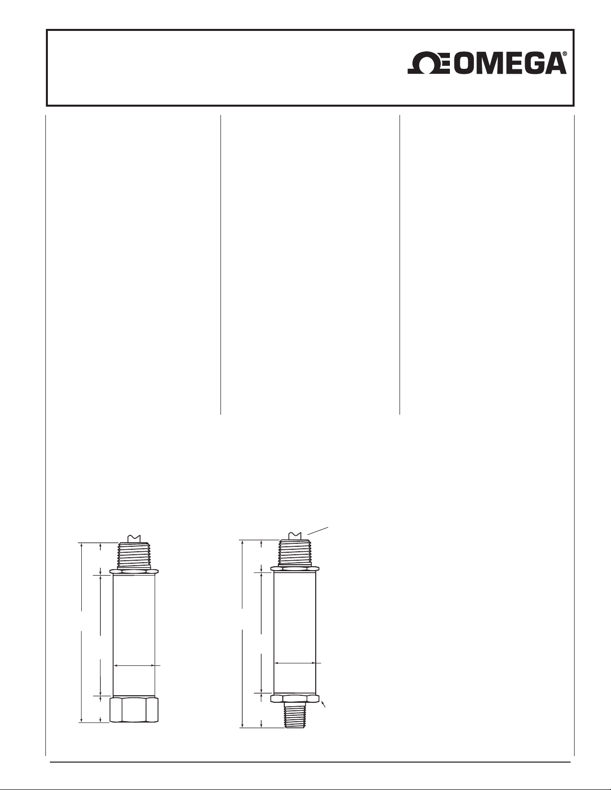
.83˝
4.78˝
3.065˝
.675˝
1.06˝
DIA.
.83˝
4.78˝
3.065˝
.885˝
1.06˝ (27) Hex.
Common For All
Pressure Fittings
(21)
(121)
(78)
(17)
(22)
(78)
(121)
(21)
(27)
1.06˝
DIA.
(27)
.83˝
4.78˝
3.065˝
.885˝
1.06˝ (27) Hex.
Common For All
Pressure Fittings
(22)
(78)
(121)
(21)
1.06˝
DIA.
(27)
PRESSURE TRANSMITTER
INSTRUCTION SHEET
M-5089/0112
WARNING! READ
BEFORE INSTALLATION
1. GENERAL:
A failure resulting in injury or dam-
ge may be caused by excessive
a
overpressure, excessive vibration or
pressure pulsation, excessive instrument temperature, corrosion of the
pressure containing parts, or other
misuse.
2. OVERPRESSURE:
Pressure spikes in excess of the rated
overpressure capability of the transducer may cause irreversible electri-
cal and/or mechanical damage to the
pressure measuring and containing
elements.
Fluid hammer and surges can destroy
any pressure transducer and must
always be avoided. A pressure snubber
should be installed to eliminate the
damaging hammer effects. Fluid hammer occurs when a liquid flow is suddenly stopped, as with quick closing
solenoid valves. Surges occur when
flow is suddenly begun, as when a
pump is turned on at full power or a
alve is quickly opened.
v
iquid surges are particularly damag-
L
ing to pressure transducers if the pipe
is originally empty. To avoid damaging
surges, fluid lines should remain full (if
possible), pumps should be brought up
to power slowly, and valves opened
slowly. To avoid damage from both fluid
hammer and surges, a surge chamber
should be installed.
Symptoms of fluid hammer and surge's
damaging effects:
• Pressure transducer exhibits an output at zero pressure (large zero offset).
• Pressure transducer output remains
constant regardless of pressure
• In severe cases, there will be no output.
FREEZING:
Prohibit freezing of media in pressure
port. Unit should be drained (mount in
vertical position with electrical termination upward) to prevent possible overpressure damage from frozen media.
3. STATIC ELECTRICAL CHARGES:
Any electrical device may be suscepti-
le to damage when exposed to static
b
electrical charges. To avoid damage to
the transducer observe the following:
• Operator/installer should follow the
proper ESD (electrostatic discharge)
protection procedures before handling
the pressure transducer.
• Ground the body of the transducer
BEFORE making any electrical
connections
• When disconnecting, remove the
ground LAST!
Note: The shield and drain wire in the
cable (if supplied) is not connected to
the transducer body, and is not a suitable ground.
Omega®PX835 Pressure Transmitter, Typical Dimensions and Construction*
Conduit
electrical
termination
Dimensions and construction details may vary based on product specified.
*
Page 3

PX835 EXPLOSION/FLAME PROOF
+
+
–
P
OWER
SUPPLY
(
+)
(
–)
TRANSDUCER
–
V
+
V–
P
IN 1
P
IN 2
4-20mA
METER
OR OTHER DEVICE
+
+
–
–
POWER
SUPPLY
METER
OR OTHER DEVICE
TRANSDUCER
(
Common)
(+ Power)
(+ Output)
PIN 1
PIN 2
PIN 3
3-Wire Voltage
.830
FLYING LEADS
ELECTRICAL TERMINATION
CONDUIT - 1/2 NPT MALE
1.062
.830
PIGTAIL
ELECTRICAL TERMINATION
CONDUIT - 1/2 NPT MALE
(C1), (P7)
1.062
.830
FLYING LEADS
ELECTRICAL TERMINATION
CONDUIT - 1/2 NPT MALE
(C2), (C3), (C4)
1.062
PRESSURE TRANSMITTER
INSTRUCTION SHEET
M-5089/0112
Mounting
The PX835 transmitter requires no
special mounting hardware, and can be
mounted in any plane with negligible position error.
Although the unit can withstand normal
vibration without damage or significant
output effects, it is always good practice
to mount the transducer where there is
minimum vibration.
For units with NPT type pressure fittings
apply Teflon
®
tape or an equivalent
sealant to the threads before installing.
When tightening, apply a wrench to the
hex wrench flats located just above the
pressure fitting. DO NOT tighten by using
a pipe wrench on the housing.
Power Supply
Power Supply Voltage
Output Signal Min Max
1-5Vdc 10V 30V
4-20mA* 12V 36V**
* For transmitters with 4-20mA output
signal, the minimum voltage at the teminals is 12Vdc. However, the minimum
supply voltage should be calculated
using the following graph and formula.
** For Intrinsically Safe Installations max,
supply voltage is 30Vdc.
Loop Supply Voltage vs. Loop Resistance
1000
800
600
400
200
Loop Resistance (Ohms)
Vmin = 12V+ (.022A x RL) (includes a 10% safety factor)
R
= RS+ R
L
RL= Loop Resistance (ohms)
R
= Sense Resistance (ohms)
S
= Wire Resistance (ohms)
R
W
30 Vdc max for
Intrinsically Safe
Installations
0
10
Loop Supply Voltage (Vdc)
W
Operating
Region
20
Noise
For minimum noise susceptibility, avoid
running the transducer’s leads in a conduit that contains high current AC power
cables. Where possible avoid running the
cable near inductive equipment..
Wire Voltage Current
Color Output Output
Red (+) Power (+) Power
White (+) Output None
Black (–) Power (–) Power
PX835 Wiring Diagrams
PX835 transducer has internal
transient protection: for safety, limit
line-to-ground voltage to 36 Vdc max.
HAZARDOUS AREA CERTIFICATIONS
Explosion Proof* – cUL: Specify A2X
Class I, Div. 1 & 2, Groups A, B, C and D
Class II, Div. 1 & 2, Groups E, F and G
Flame Proof* – ATEX: Specify A2X
II 2 GD
Ex d IIC T4
Ex nC IIC T4
Intrinsically Safe (applies to 4-20mA) FM/CSA:
Intrinsic Safety: Class I, II and III Div.1 and 2,
Non-Incendive: Class I, II and III Div.1 and 2,
See Omega drawing #825A027
Groups A, B, C, D, F and G, no
barriers needed
Wire Voltage Current
Color Output Output
Red (+) Power (+) Power
White (+) Output None
Black (–) Power (–) Power
* Model PS835 enclosure is intended for
installation using metallic conduit and
requires installer to comply with appropriate codes to complete proper installation
30
36
to meet the assigned hazardous area
designation.
SHIELDED CABLE (PIG TAIL)
ELECTRICAL TERMINATION
CONDUIT - 1/2NPT MALE
Page 4

OMEGAnet®Online Service Internet e-mail
omega.com info@omega.com
Servicing North America:
B
U.S.A.: Omega Engineering, Inc., One Omega Drive, P.O. Box 4047
ISO 9001 Certified S
C
anada:
tamford, CT 06907-0047
Toll-Free: 1-800-826-6342 Tel: (203) 359-1660
FAX: (203) 359-7700 e-mail: info@omega.com
976 Bergar
Laval (Quebec), Canada H7L 5A1
Toll-Free: 1-800-826-6342 TEL: (514) 856-6928
FAX: (514) 856-6886 e-mail: info@omega.ca
enelux:
Czech Republic: Frystatska 184
F
rance:
For immediate technical or application assistance:
U.S.A. and Canada: Sales Service: 1-800-826-6342/1-800-TC-OMEGA
Customer Service: 1-800-622-2378/1-800-622-BEST
Engineering Service: 1-800-872-9436/1-800-USA-WHEN
®
®
Mexico: En Español: 001 (203) 359-7803 FAX: (001) 203-359-7807
info@omega.com.mx e-mail:espanol@omega.com
It is the policy of OMEGA Engineering, Inc. to comply with all worldwide safety and EMC/EMI regulations that apply. OMEGA is constantly pursuing certification of its
roducts to the European New Approach Directives. OMEGA will add the CE mark to every appropriate device upon certification.
p
he information contained in this document is believed to be correct, but OMEGA accepts no liability for any error s it contains, and reserves the right to alter specifications without notice.
T
WARNING: These products are not designed for use in, and should not be used for, human applications.
G
ermany/Austria:
®
United Kingdom: OMEGA Engineering Ltd.
ISO 9001 Certified O
Servicing Europe:
Managed by the United Kingdom Office
Toll-Free: 0800 099 3344 TEL: +31 20 347 21 21
FAX: +31 20 643 46 43 e-mail: sales@omega.nl
33 01 Karviná, Czech Republic
7
Toll-Free: 0800-1-66342 TEL: +420-59-6311899
FAX: +420-59-6311114 e-mail: info@omegashop.cz
Managed by the United Kingdom Office
oll-Free: 0800 466 342 TEL: +33 (0) 161 37 29 00
T
FAX: +33 (0) 130 57 54 27 e-mail: sales@omega.fr
Daimlerstrasse 26, D-75392 Deckenpfronn, Germany
Toll-Free: 0 800 6397678 TEL: +49 (0) 7059 9398-0
FAX: +49 (0) 7056 9398-29 e-mail: info@omega.de
ne Omega Drive, River Bend Technology Centre, Northbank
Irlam, Manchester M44 5BD England
Toll-Free: 0800-488-488 TEL: +44 (0)161 777-6611
FAX: +44 (0)161 777-6622 e-mail: sales@omega.co.uk
WARRANTY/DISCLAIMER
OMEGA ENGINEERING, INC. warrants this unit to be free of defects in materials and workmanship for a period of 13 months from date of purchase.
OMEGA’s WARRANTY adds an additional one (1) month grace period to the normal one (1) year product warranty to cover handling and
shipping time. This ensures that OMEGA’s customers receive maximum coverage on each product.
If the unit malfunctions, it must be returned to the factory for evaluation. OMEGA’s Customer Service Department will issue an Authorized Return (AR)
number immediately upon phone or written request. Upon examination by OMEGA, if the unit is found to be defective, it will be repaired or replaced
at no charge. OMEGA’s WARRANTY does not apply to defects resulting from any action of the purchaser, including but not limited to mishandling,
improper interfacing, operation outside of design limits, improper repair, or unauthorized modification. This WARRANTY is VOID if the unit shows
evidence of having been tampered with or shows evidence of having been damaged as a result of excessive corrosion; or current, heat, moisture or
vibration; improper specification; misapplication; misuse or other operating conditions outside of OMEGA’s control. Components in which wear is not
warranted, include but are not limited to contact points, fuses, and triacs.
OMEGA is pleased to offer suggestions on the use of its various products. However, OMEGA neither assumes responsibility for any
omissions or errors nor assumes liability for any damages that result from the use of its products in accordance with information provided
by OMEGA, either verbal or written. OMEGA warrants only that the parts manufactured by the company will be as specified and free of
defects. OMEGA MAKES NO OTHER WARRANTIES OR REPRESENTATIONS OF ANY KIND WHATSOEVER, EXPRESSED OR IMPLIED, EXCEPT
THAT OF TITLE, AND ALL IMPLIED WARRANTIES INCLUDING ANY WARRANTY OF MERCHANTABILITY AND FITNESS FOR A PARTICULAR
PURPOSE ARE HEREBY DISCLAIMED. LIMITATION OF LIABILITY: The remedies of purchaser set forth herein are exclusive, and the total
liability of OMEGA with respect to this order, whether based on contract, warranty, negligence, indemnification, strict liability or otherwise,
shall not exceed the purchase price of the component upon which liability is based. In no event shall OMEGA be liable for consequential,
incidental or special damages.
CONDITIONS: Equipment sold by OMEGA is not intended to be used, nor shall it be used: (1) as a “Basic Component” under 10 CFR 21 (NRC), used in
or with any nuclear installation or activity; or (2) in medical applications or used on humans. Should any Product(s) be used in or with any nuclear
installation or activity, medical application, used on humans, or misused in any way, OMEGA assumes no responsibility as set forth in our basic
WARRANTY/ DISCLAIMER language, and, additionally, purchaser will indemnify OMEGA and hold OMEGA harmless from any liability or damage
whatsoever arising out of the use of the Product(s) in such a manner.
Direct all warranty and repair requests/inquiries to the OMEGA Customer Service Department. BEFORE RETURNING ANY PRODUCT(S) TO OMEGA,
RETURN REQUESTS/INQUIRIES
PURCHASER MUST OBTAIN AN AUTHORIZED RETURN (AR) NUMBER FROM OMEGA’S CUSTOMER SERVICE DEPARTMENT (IN ORDER TO AVOID
PROCESSING DELAYS). The assigned AR number should then be marked on the outside of the return package and on any correspondence.
The purchaser is responsible for shipping charges, freight, insurance and proper packaging to prevent breakage in transit.
FOR WARRANTY
available BEFORE contacting OMEGA:
1. Purchase Order number under which the product was PURCHASED,
2. Model and serial number of the product under warranty, and
3. Repair instructions and/or specific problems relative to the product.
OMEGA’s policy is to make running changes, not model changes, whenever an improvement is possible. This affords our customers the latest in technology and
engineering. OMEGA is a registered trademark of OMEGA ENGINEERING, INC.
© Copyright 20 09 OMEGA ENGINEERING, INC. All rights reserved. This document may not be copied, photocopied, reproduced, translated, or reduced to any electronic
medium or machine-readable form, in whole or in part, without the prior written consent of OMEGA ENGINEERING, INC.
RETURNS, please have the following information
FOR NON-WARRANTY REPAIRS,
consult OMEGA for current repair charges.
Have the following information available BEFORE contacting OMEGA:
1. Purchase Order number to cover the COST of the repair,
2. Model and serial number of the product, and
3. Repair instructions and/or specific problems relative to the product.
 Loading...