

Page 1
OMB-DAQSCAN-2000 Series
Extended Warranty
Program
SM
Ethernet-Based Data Acquisition System Components
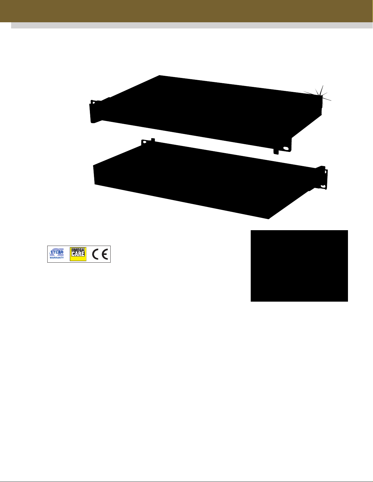
OMB-DAQSCAN-2005, front
and back, shown smaller than
actual size
OMB-DAQSCAN-2001
and OMB-DAQSCAN2005
⻬ Adds Analog I/O, Digital
I/O and Frequency I/O
to Ethernet-Based
Test Systems
⻬ All I/O Can Be
Synchronous, Enabling
Precise Timing Between
Various I/O Functions
⻬ 8 Differential or 16
Single-Ended Inputs,
Expandable up to 256
Voltage or 896
Thermocouple Channels
Using Signal
Conditioning and
Expansion Options
⻬ Up to 40 Built-In
TTL-Level Digital I/O,
Expandable Up to 256
Channels of Isolated
I/O Using Low-Cost
Isolation Modules
⻬ Includes Support
for Visual Basic,
C/C++, Windows
2000/XP/VISTA
ActiveX/COM, LabVIEW,
MATLAB and DASYLab
⻬ Convenient 1U high 19"
Rack-Mount Package
Minimizes Rack Space
in Test Systems
⻬ Includes Out-of-the-Box
DaqView Software to
Facilitate Signal and
Wiring Verification with
No Programming
Required
The OMB-DAQSCAN-2000 Series
of Ethernet-based data acquisition
system components provides
analog, digital and frequency I/O
capability for Ethernet-based test
systems.
All OMB-DAQSCAN-2000 models
are packaged in a 1U high-full rack
package and include a rack-mount
kit that can attach to either the front
DaqView Software Real-Time Chart
or the rear of the enclosure.
Multiple OMB-DAQSCAN models
can be combined in the same
system and synchronized using a
simple SYNC connection between
units. All I/O is accessed via female
DB37 connectors located at the rear
of the unit, making cabling easy
from the OMB-DAQSCAN-2000 to
your device-under-test.
The OMB-DAQSCAN-2000 Series
includes comprehensive drivers for
all popular Windows-based
environments, including Visual
Basic, C/C++, ActiveX/COM,
LabVIEW, MATLAB, and DASYLab.
C-1
Page 2

OMB-DAQSCAN-2000 Series Selection Chart
Dgital Frequency/Pulse Timer Analog
Model Number Analog Inputs I/O Inputs Outputs Outputs
OMB-DAQSCAN-2001 16 single-ended/8 differential 40 4 24
OMB-DAQSCAN-2005 16 single-ended/8 differential 40 420
Also included with the OMB-DAQSCAN-2000 Series
is DaqView, an interactive spreadsheet-style
application that is ideal for verifying signal
connections during system design.
The compact 1U high 19” rack packaging of the
OMB-DAQSCAN-2000 make it a compact component
for rack-based systems. In addition to the built-in I/O
provided by the OMB-DAQSCAN-2000 Series, a wide
variety of signal conditioning and expansion options
are available.
C
Below are some sample systems that can be
derived from the OMB-DAQSCAN-2000 along
with OMB-DBK options.
High Channel Count
Thermocouple Measurements
When combined with the OMB-DBK90 thermocouple
input module, the OMB-DAQSCAN-2000 Series can
measure up to 896 channels of T/C input. In the
example system to the right, any T/C type can be
installed into any channel using standard mini T/C
connectors. Each 56-channel OMB-DBK90 option
consumes 2U of rack space and can be mounted
on the front or rear of the rack chassis. Built-in cold
junction compensation coupled with T/C conversion
algorithms built into the software make temperature
measurements easy. Thermocouples are measured
at 1 ms/channel in a system based on the
OMB-DBK90.
High-Isolation Voltage
and Thermocouple Measurements
The OMB-DAQSCAN can be combined with the
OMB-DBK207/CJC options to create an isolated
system capable of measuring up to 256 channels
of voltage, thermocouple, RTD and strain gage
inputs. All input channels can be scanned up to
200 kHz and are isolated by 500 V from other
channels and from system common. Any
combination of input signals is possible by
selecting the appropriate OM5 signal conditioning
module for the OMB-DBK207/CJC.
DaqView Software Real-Time Display
The 168 TC channel system consists of one
OMB-DAQSCAN-2005 plus three OMB-DK90
modules with rack-mount kits
OMB-DBK207/CJCs can be mounted at the
front or rear of the rack. They attach to the
OMB-DAQSCAN via a simple OMB-CA-37-10 cable.
C-2
The 24-channel isolated system includes an
OMB-DAQSCAN-2005 plus two OMB-DBK207/CJC
boards. The system is capable of scanning all
channel and provides 500 V isolated for all inputs
Page 3

High-Speed Voltage
Extended Warranty
Program
SM
Measurement System
The OMB-DAQSCAN-2005 can
be combined with OMB-DBK85
16-channel voltage input
modules to build a 5 µs/channel
voltage measurement system
with up to 256 channels. All
inputs can have a different
software programmable input
range, from 156 mV FS to 10 V
FS, programmable on a perchannel basis. The 16 BNC
inputs on the OMB-DBK85 can
be accessed from either the front
or the rear of a rack system.
The 80-channel high-speed scanning system consists of an
OMB-DAQSCAN-2005 plus five OMB-DBK85 16-channel
voltage scanning modules. All channels can be measured
at the maximum rate of 5 µs/channel
OMB-DAQSCAN-2005,
front and back, shown
smaller than actual size
Multifunction I/O System
All of the foregoing capabilities can be
combined into a single system using
one OMB-DAQSCAN-2001 as the
system centerpiece.
The system provides 56 non-isolated TC
inputs, 16 isolated voltage inputs, 4 analog
outputs, 4 frequency inputs and 32 isolated
discrete high-volage outputs.
Shown from top to bottom with 1 OMB-DBK208
screw-terminal board, 1 OMB-DBK207,
1 OMB-210, 1 OMG-DBK90 and 1 OMB-DBK85
DaqView Software Real-Time Display
C-3
Page 4

DaqView Software
Hardware
Configuration
Specifications
GENERAL
Supply Voltage Range: 90 to 250 Vac
Power Required: 15 W (assuming no
OMB-DBK options)
Operating Temperature: 0 to 50°C (32 to 122°F)
Storage Temperature: -40 to 80°C (-40 to 176° F)
Relative Humidity: 0 to 95%, non-condensing
Signal I/O Connector: DB37 male for P1, P2 and P3
Dimensions: 425 W x 220 D x 45 mm H
(16.75 x 8.5 x 1.75”)
Weight: 2.3 kg (5 lbs)
Power Available for External DBK Options: 10W
A/D SPECIFICATIONS
Type: Successive approximation
Resolution: 16-bit
Conversion Time: 5 µs
Maximum Sample Rate: 200 kHz
Non-linearity (Integral): ±1 LSB
Non-linearity (Differential): No missing codes
C
Accuracy**
One Year, 0 to 35°C
Voltage Range* (% reading + % range
Absolute
0 to +10 V 0.015 + 0.005
0 to +5 V 0.015 + 0.005
0 to +2.5 V 0.015 + 0.005
0 to +1.25 V 0.015 + 0.008
0 to +0.625 V 0.015 + 0.008
0 to +0.3125 V 0.015 + 0.008
-10 to +10 V 0.015 + 0.005
-5 to +5 V 0.015 + 0.005
-2.5 to +2.5 V 0.015 + 0.005
-1.25 to +1.25 V 0.015 + 0.005
-0.625 to +0.625 V 0.015 + 0.008
-0.3125 to +0.3125 V 0.015 + 0.008
-0.156 to +0.156 V 0.02 + 0.008
* Specifications ussume differential input single channel scan,
2000 kHz scan rate, unfiltered
** Accuracy specficiation is exclusive of noise
Bias Current: <1nA (0 to 35°C)
Common Mode Rejection: 86 dB, DC to 60 Hz for
gains < = 8; >100 dB for gains > = 16
Maximum Input Voltage (Without Damage):
±11 V relative to analog common
Over-Voltage Protection: ±35 V
Ranges: Software or sequencer-selectable
on a per-channel basis
Crosstalk: -100 dB DC to 60 Hz; 86 dB @ 10 kHz
ANALOG INPUTS
Channels
OMB-DAQSCAN-2001, OMB-DAQSCAN-2005:
16 single-ended or 8 differential, programmable on a
per-channel basis as single-ended or differential and
unipolar or bipolar
Expansion: Up to 896 TC channels when used with
OMB-DBK90 expansion option (1 ms/channel), or up
to 256 channels when used with all other expansion
options (5 µs/channel)
Settling Time: 5 µsec to 1 LSB for full-scale step
Temperature Coefficient: ±(10 ppm +0.3 LSB)/˚C
outside the range of 0 to 35°C
Input Impedance: 10 MΩ (single-ended),
20M Ω (differential)
INPUT SEQUENCER
Analog, digital and frequency inputs can be scanned
synchronously, based on either an internal
programmable timer or an external clock source.
Scan Clock Sources: 2
1. Internal, programmable from 5 µs to 5.96 hours
in 1 µs steps
2. External, TTL level input up to 200 kHz max:
Programmable parameters per scan: Channel (random
order), gain, unipolar/bipolar
Depth: 16,384 locations
On-Board Channel-to-Channel Scan Rate: 5 or 10 µs
per channel, programmable
Expansion Channel Scan Rate: 5 µs, 10 µs, or 1000
µsec per channel, programmable
C-4
Page 5

External Acquisition Scan
Clock Input
Maximum Rate: 200 kHz
Clock Signal Range: 0 V to 5 V
Minimum Pulse Width: 50 ns high,
50 ns low
External SYNC Port: Available on
rear panel, allows multiple DaqScan
units to be scan-synchronous
(post trigger)
TRIGGERING
Trigger Sources: 6, individually
selectable for starting and stopping
an acquisition. Stop acquisition can
occur on a different channel than
start acquisition; stop acquisition
can be triggered via modes 2, 4, 5
or 6, described below.
1. Single-Channel Analog
Hardware Trigger
Any analog input channel can be
software-programmed as the
analog trigger channel, including
any of the 256 analog expansion
channels.
2. Single-Channel Analog
Software Trigger
Any analog input channel, including
any of the 256 analog expansion
channels, can be selected as the
software trigger channel. If the
trigger channel involves a
calculation, such as temperature,
then the driver automatically
compensates for the delay
required to obtain the reading,
resulting in a maximum latency of
one scan period.
3. Single-Channel Digital Trigger
A separate digital input is provided
for digital-triggering.
4. Digital Pattern Triggering
8- or 16-bit pattern triggering on any
of the digital input ports.
Programmable for trigger on equal,
above, below, or within/outside of a
window. Individual bits can be
masked for “don’t care” condition.
5. Counter/Totalizer Triggering
Counter/totalizer inputs can trigger
an acquisition. User can select to
trigger on a frequency or on total
counts that are equal, above, below
or within/outside of a window.
6. Software Triggering
Trigger can be initiated under
program control.
DaqView-Software includes an Excel add-on for seamless execution
with Microsoft Excel’s tool palette
ANALOG OUTPUT
(MODELS OMB-DAQSCAN-2001
AND OMB-DAQSCAN-2004)
The four analog output channels
are updated synchronously relative
to scanned inputs, and clocked from
either an internal onboard clock or
an external clock source. Analog
outputs can also be updated
asynchronously, independent of
any other scanning in the system.
Channels: 4
Resolution: 16-bits
Data Buffer: 256 Ksample
Output Voltage Range: ±10 V
Output Current: ±10 mA
Offset Error: ±0.0045 V max
Digital Feedthrough: 50 mV
when updated
Gain Error: ±0.01%
Update Rate: 100 kHz max,
1.5 Hz min (no minimum with
external clock)
Settling Time: 10 µsec max to 1
LSB for full-scale step
Clock Sources: 4, programmable
1. Onboard D/A clock, independent
of scanning input clock
2. Onboard scanning input clock
3. External D/A input clock,
independent of external scanning
input clock
4. External scanning input clock
DIGITAL I/O
Channels: 40, expandable up to
272 with external digital OMB-DBK
options
Input Scanning Modes: 2
1. Asynchronous, under program
control at any time relative to input
scanning
2. Synchronous with input scanning
Ports: 3x 8-bit (82C55 emulation),
and 1x 16-bit; each port is
programmable as input or output
Input Protection: ±8 KV ESD
clamp diodes parallel
I/O Levels: TTL
Sampling Rate: 200 kHz max
Update Rate: Asynchronous under
program control
FREQUENCY/PULSE COUNTERS
Counter inputs can be scanned
synchronously along with analog
and digital scanned inputs,
based either on internal
programmable timer or an external
clock source. Counters can be
configured to clear when read or to
totalize and clear under program
control.
Channels: 4x 16-bit;
cascadable as 2x 32-bit
Frequency Measurement
Rate: 10 MHz max
Input Signal Range:
-15 V to 15 V
Trigger Level: TTL
C-5
Page 6

ALL MODELS AVAILABLE FOR FAST DELIVERY!
Extended Warranty
Program
SM
To Order Visit omega.com/omb-daqscan-2000 for Pricing and Details
Model Number Description
OMB-DAQSCAN-2001 Ethernet system with 16 single-ended/8 differential 250 Khz 16-bit analog
inputs, 40 digital I/O, 4 analog outputs, 4 frequency/pulse counters
and 2 frequency/pulse generators
OMB-DAQSCAN-2005 Ethernet system with 16 single-ended/8 differential 250 Khz 16 bit analog
inputs, 40 digital I/O, 4 frequency/pulse counters and 2 frequency/pulse generators
All OMB-DAQSCAN-2000 models include 10/100 BaseT Ethernet interface, Daqview Software, drivers for LabVIEW, DASYLab, C++,
Visual Basic and ActiveX/COM; DB37 connectors, external SYNC, complete operator’s manual on CD ROM and rack-mount kit also
included.
Ordering Example: OMB-DAQSCAN-2005, Ethernet system and OMEGACARE SM1 year extended warranty (adds 1 year to standard
1 year warranty) for OMB-DAQSCAN-2005 and OMB-DBK206 screw-terminal board and OMB-CA-37-1 cable.
Terminal Panels Expansion/Signal Conditioning Options
Model Number Description
OMB-DBK84* 14-channel thermocouple/mV input module, requires OMB-CA-37-x cable
OMB-DBK90* 56-channel thermocouple input module, requires OMB-CA-37-x cable
OMB-DBK85* 16-channel differential input module with BNC connectors, requires OMB-CA-37-x cable
OMB-DBK207/CJC* 16-channel isolated Analog Signal Conditioning, requires OM5 signal conditioning
modules and OMB-CA-137-x cable
OMB-DBK208 16-channel isolated discrete I/O signal conditioning, requires isolated I/O modules
and OMB-CA-137-x cable
OMB-DBK206 Screw terminal board, requires OMB-CA-37-x cable
* Used with OMB-DAQSCAN’s analog inputs, i.e., OMB-DAQSCAN-2001 and OMB-DAQSCAN-2005
C
Cables and Rack Mount Kits
Model Number Description
OMB-CA-37-1 37-pin cable, 7" long, connects OMB-DAQSCAN to expansion panels
Minimum Pulse Width:
50 ns high, 50 ns low
Channels: 4x 16-bit;
cascadable as 2x 32-bit
Frequency
Measurement
Rate: 10 MHz max
Input Signal Range:
-15 V to 15 V
Trigger Level: TTL
Minimum Pulse Width:
50 ns high, 50 ns low
FREQUENCY/PULSE
GENERATORS
Channels: 2x 16-bit
Output Waveform:
Square wave
Output Rate: 1 MHz
base rate divided by
1 to 65,535
(programmable)
High-Level
Output Voltage:
2.0 V min @ -3.75 mA
3.0 V min @ -2.5 mA
Low-Level
Output Voltage:
0.4 V max @ 2.5 mA
Other Compatible Signal Conditioner/Expansion Modules and Cards
Model Number Description
OMB-DBK2 4-channel D/A voltage-output card
OMB-DBK4 2-channel dynamic signal-input card
OMB-DBK5 4-channel current output card
OMB-DBK7 4-channel frequency-input card
OMB-DBK8 8-channel high-voltage input card
OMB-DBK9 8-channel RTD Measurement card
OMB-DBK15 Universal current/voltage input card
OMB-DBK16 2-channel strain-gage card
OMB-DBK20 48-line digital I/O card
OMB-DBK21 48-line digital I/O card
OMB-DBK24 24-line optically isolated digital-output module
OMB-DBK43A 8-channel strain-gage module
OMB-DBK50 8-channel isolated voltage-input module
OMB-DBK80 16-channel differential input voltage card
OMEGACARESMextended warranty program is
available for models shown on this page. Ask
your sales representative for full details when
placing an order. OMEGACARE
labor and equivalent loaners.
with screw-terminal connectors
with screw-terminal connectors
SM
C-6
covers parts,
 Loading...