

Page 1

High-Performance PCI-Based
Extended Warranty
Program
SM
Data Acquisition Boards
OMB-DAQBOARD-2000 Series
Starts at
$
689
⻬ 5 Models Available
⻬ 16-Bit, 200 kHz A/D
Converter
⻬ 8 Differential or
16 Single-Ended Analog
Inputs (Software
Selectable per Channel)
⻬ Expandable Up to
256 Analog Input Channels,
While Maintaining 200 kHz
(5 µs per Channel)
Scan Rate
⻬ Up to 4 Boards Can be
Installed into One PC
for Up to 1024 Analog
Input Channels
⻬ 100% Digital Calibration
⻬ 512-Location
Channel/Gain FIFO,
Capable of Scanning
All Channels, Including
256 Analog Expansion
Channels and Digital/
Counter Channels,
at 5 µs per Channel
⻬ DMA Bus Mastering for
Synchronous Analog I/O,
Digital I/O, and Counter
Inputs
OMEGACARESMextended warranty program is available for
models shown on this page. Ask your sales representative for
full details when placing an order. OMEGACARE
parts, labor and equivalent loaners.
⻬ Trigger Modes Include
Analog, Digital, and
Software, with <5 µs
Latency
⻬ Virtually Infinite
Pre-Trigger Buffer
⻬ Up to Four 16-Bit,
100 kHz Analog
Outputs with Infinite
Continuous Waveform
Output Capability
⻬ 40 Digital I/O Lines,
Can be Scanned
Synchronously or
Asynchronously
with Analog Inputs
⻬ Digital I/O is
Expandable Up to
272 Lines, Including
Optional Isolation and
Relay Closure
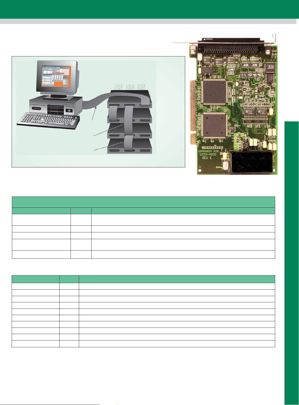
OMB-DAQBOARD-2000, $799,
shown smaller than actual size.
SM
covers
⻬ 4 Counter/Pulse Input
Channels Can be
Scanned Synchronously
or Asynchronously with
Analog Inputs
⻬ 2 Timer/Pulse
Output Channels
⻬ Signal Conditioning and
Expansion Options for
Thermocouples, Strain
Gages, Accelerometers,
Isolation, and RTDs—
Over 30 Options in All
⻬ Includes DaqView
Windows Software;
DaqX API Library, Drivers
for Visual Basic, C++, and
Delphi for Windows 95
and Higher; C++ for
Linux; DASYLab,
TestPoint, and LabVIEW
D1-1
Page 2

OMB-DAQBOARD-2000 Series Selection Chart
OMB-DAQBOARD Models I/O
Feature 2001 2000 2005 2004 2002
Analog Inputs (P1)
(16 bit/200 kHz)
Analog Outputs (P3)
16 bit/100 kHz)
Digital I/O (P2, P3) 40 40 40 40 40
Freq./pulse I/O (P3) 6 6 6 6 6-
The OMB-DAQBOARD-2000 Series
sets the price/performance
benchmark for high-speed,
multifunction plug-and-play data
acquisition for PCI bus computers.
The hardware design offers all the
features normally found on
significantly more expensive boards,
including 16-bit, 200 kHz A/D; 100%
digital calibration; bus mastering,
two or four 16-bit, 100 kHz A/D
converters; 40 digital I/O lines;
4 counters; and 2 timers.
The OMB-DAQBOARD-2000 Series
is supported by a growing family
of over 30 signal conditioning and
expansion options, offering signal
conditioning for thermocouples,
RTDs, accelerometers, isolation,
high voltage, strain gages, and
much more. Up to 528 channels
of analog and digital I/O can
be accessed with one
OMB-DAQBOARD-2000, while
maintaining the 5 µs per channel
update rate. Up to 4
OMB-DAQBOARD-2000s can
be installed into one PC.
The OMB-DAQBOARD-2000 has
more extensive software capabilities
than most other boards, with
comprehensive drivers for nearly
every programming environment
supported by Windows 95 and
higher. Included in this list are
Visual Basic, C++, Delphi,
TestPoint, LabVIEW, and
DASYLab, and C++ for Linux.
Also included is a suite of DaqView
software options for setup,
acquisition, display, and analysis
of acquired data—no programming
required.
16 16 16 - -
42-4 -
Synchronous I/O
for High-Speed Applications
The OMB-DAQBOARD-2000 Series
sets a new standard with its ability
to make analog measurements,
read digital inputs, and read counter
inputs, while synchronously
generating up to 4 analog outputs
and/or a 16-bit digital pattern output.
Most other boards require CPU
interaction to access I/O other than
analog input, making it impossible to
generate time-critical analog
waveforms or digital patterns. With
the OMB-DAQBOARD-2000 Series,
the true power of PCI-based PCs
can be unleashed.
The same synchronous features of
the OMB-DAQBOARD-2000 extend
to its family of OMB-DBK signal
conditioning and expansion options.
Up to 256 analog input channels
and 272 (P2 only) digital I/O
channels can also be accessed
synchronously to one another, with
precise and deterministic channelto-channel timing. Up to 4
OMB-DAQBOARD-2000s can be
installed in one PC, quadrupling the
channel capacity to over 1000
analog input channels, 1000 digital
I/O channels, and 16 high-speed
analog output channels.
Signal I/O
One 100-pin connector on the
OMB-DAQBOARD-2000 Series
provides access to all the
input and output signals. Unlike
other multifunction boards that
require multiple PC slots, the
OMB-DAQBOARD-2000 Series
accommodates all I/O using one
cable and has only one PCI slot.
The 100-pin OMB-DAQBOARD/2000
Series I/O connector, P4, is logically
divided into 3 subports: P1, P2, and
D1-2
P3. P1, the analog input port,
contains all of the analog input
channels, as well as the sequencer
control signals for accessing
external analog input options. All
analog expansion options attach to
the P1 port. P2, the general purpose
digital I/O port, can be used directly
to control and monitor 24 digital I/O
lines. P2 can also function as the
digital I/O expansion port, whereby
the 24 lines are exclusively used to
control external digital OMB-DBK
expansion options, for up to 256
lines of digital input or output. P3
contains an additional 16-bit digital
I/O port, as well as the counter
inputs, timer outputs, and analog
outputs. Several options are
available to provide easy user
access to all of the I/O signals on P4.
Analog Input (P1)
The OMB-DAQBOARD-2000 Series
has a 16-bit, 200 kHz A/D coupled
with 16 single-ended or 8 differential
analog inputs. Thirteen softwareprogrammable ranges provide
inputs from ±10 V to ±156 mV full
scale. Each channel can be
software configured for a different
range, as well as for single-ended or
differential and unipolar or bipolar
inputs. Beyond the 16 built-in
analog inputs, the user can expand
the OMB-DAQBOARD-2000 Series
up to 256 analog inputs using
external OMB-DBK signal
conditioning and expansion options.
As with the on-board channels,
expansion channels are scanned
at the same 5 µs/channel rate
(200 kHz), and most are software
programmable for range. There is
no speed penalty for scanning
expansion channels versus built-in
channels. The OMB-DBK expansion
options offer a wide variety of signal
measurements, including
thermocouples, RTDs, strain gages,
accelerometers, high voltage,
isolation, current, and much more.
D1
ANALOG INPUT AND
MULTIFUNCTION CARDS
Page 3
Scanning
The OMB-DAQBOARD-2000 Series
has an on-board scan sequencer
that permits the user to select any
combination of up to 512 channel/
range combinations. The sequencer
scans all channels contained in the
sequence at the fastest rate of
5 µs/channel, thereby minimizing the
time-skew from channel-to-channel.
The user can also set the time
between scan groups, from 0 to 6 hours.
In addition to scanning analog
inputs, the sequencer can scan
digital inputs and counter inputs.
Channel-Scanning
Flexibility
The OMB-DAQBOARD-2000 Series
offers a 512-location scan
sequencer that allows the user to
select each channel and associated
input amplifier gain at random. The
sequencer circuitry circumvents a
major limitation encountered with
many plug-in data acquisition
boards—a drastic reduction in the
scan rate for external expansion
channels. All OMB-DAQBOARD-2000
Series channels, including
the 528 potential expansion
channels, are scanned at 200 kHz
(5 µs/channel). In addition, the digital
and frequency inputs can be scanned
by using the same scan sequence
employed for analog inputs, enabling
the time correlation of acquired
digital data to acquired analog data.
The OMB-DAQBOARD-2000 Series
permits each scan group, which can
contain up to 512 channel/gain
combinations, to be repeated
immediately or at a programmable
interval of up to 6 hours. Within
each scan group, consecutive
channels are measured at a fixed
5 µs/channel rate.
Bus Mastering DMA
The OMB-DAQBOARD-2000 Series
supports bus mastering DMA, which
allows analog and digital/counter input
data, as well as analog and digital
output data, to flow between the PC
and the OMB-DAQBOARD-2000
Series without consuming valuable
CPU time.
The driver supplied with the
OMB-DAQBOARD-2000, as well as
all other third-party software support
such as TestPoint, LabVIEW, and
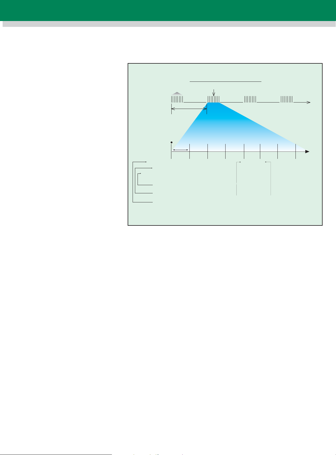
DAQBOARD Scanning Example
Channel
Unipolar or
bipolar
* DaqBoard-200 and 216 only
#2
x1
Gain
Uni Uni Bi Uni Bi Bi
Unipolar or bipolar operation can be
programmed for each channel dynamically*
Gain can be programmed for
each channel dynamically
Channels can be
sampled randomly
Scan group
Programmable,
immediately or at
intervals of
up to 10 hours
10 µ s
#4 #7 #2 D #18 #19 #16
x8 x8 x2 x100 x10
All channels within a scan group are
measured at a fixed 10 µs/channel
16 digital input lines
can also be sampled along
with the analog inputs
DASYLab, automatically use bus
mastering DMA to efficiently
conduct I/O from the PC to the
OMB-DAQBOARD-2000.
Triggering
Triggering can be the most critical
aspect of a data acquisition application.
The OMB-DAQBOARD-2000 Series
supports a full complement of
trigger modes to accommodate any
measurement situation.
Hardware Analog Triggering
Many data acquisition boards claim
analog triggering, but rely on the PC
to take readings and make a
decision, which leads to uncertain
and potentially long latencies. The
OMB-DAQBOARD-2000 Series
uses true analog triggering,
whereby the trigger level
programmed by the user sets an
analog DAC, which is then
compared in hardware to the analog
input level on the selected channel.
The result is analog trigger latency
that is guaranteed to be less than
5 µs, significantly shorter than that
of most data acquisition boards.
Any analog channel can be selected
as the trigger channel, including
built-in or expansion channels. The
D1-3
t
x1000
Uni
Expansion channels (up to
256) are sampled at the same
rate as on-board channels
user can program both the trigger
level and the edge (rising or
falling).
Digital and Pattern
Triggering (P1)
A separate digital trigger input line
is provided, allowing TTL-level
triggering, again with latencies
guaranteed to be less than 5 µs.
Both the logic levels (1 or 0) and
the edge (rising or falling) can be
programmed for the discrete
digital trigger input.
Software-Based Triggering
Software-based triggering differs
from the modes described above
because the readings—analog,
digital, or counter—are interrogated
by the PC to detect the trigger
event, not in the hardware as
described above. The advantage
of this mode is to permit triggering
based on more complex
situations, such as on a specific
temperature, which was derived
from the acquisition of at least
2 analog measurements, plus the
calculation of the measured
temperature using linearization
algorithms.
Page 4

The OMB-DAQBOARD-2000 Series
also supports digital pattern
triggering, whereby the user can
designate any of the digital input
ports as the trigger port. The
programmed digital pattern, including
the ability to mask or ignore specific
bits, is then compared to the actual
input until a match is detected, after
which the sequencer begins the
scan sequence. Triggering can also
be programmed to occur when one
of the counters reaches, exceeds,
or is within a programmed level.
Any of the built-in counter/totalizer
channels can be programmed as a
trigger source. Normally softwarebased triggering results in long
latencies from the time that a trigger
condition is detected until the actual
capturing of data commences. However,
the OMB-DAQBOARD-2000 Series
circumvents this undesirable
phenomenon by use of pre-trigger
data. Specifically, when
software-based triggering is
employed and the PC detects that a
trigger condition has occurred
(which may be thousands of
readings later than the actual
occurrence of the signal), the OMBDAQBOARD-2000 driver
automatically looks back to the
location in memory where the actual
trigger-causing measurement
occurred. The acquired data that
are presented to the user actually
begin at the point where the triggercausing measurement occurs. The
latency in this mode is equal to one
scan cycle.
Stop Trigger
Any of the software trigger modes
described above can also be used
to stop an acquisition. Thus an
acquisition can be programmed to
begin on one event, such as a
temperature level, and then can
stop on another event, such as a
digital pattern.
No pre-trigger, post-trigger stop
event.
acquires data upon receipt of the
trigger, and stops acquiring upon
receipt of the stop-trigger event.
This, the simplest of modes,
Fixed pre-trigger with post-trigger
stop event
specifies the number of pre-trigger
readings to be acquired, after
which acquisition continues until a
stop-trigger event occurs.
. In this mode, the user
No pre-trigger, infinite post-trigger.
No pre-trigger data are acquired in
this mode. Instead, data are
acquired beginning with the trigger
event, and are terminated when the
operator issues a command to halt
the acquisition.
Fixed pre-trigger with infinite posttrigger.
the amount of pre-trigger data to
acquire, after which the system
continues to acquire data until the
program issues a command to halt
acquisition.
The user specifies
Variable pre-trigger with
post-trigger stop event (driver
support only).
pre-trigger modes, this mode does
not have to satisfy the pre-trigger
number of readings before
recognizing the trigger event. Thus
the number of pre-trigger readings
acquired is variable and dependent
on the time of the trigger event
relative to the start. In this mode,
data continue to be acquired until
the stop-trigger event is detected.
Unlike the previous
Variable pre-trigger with infinite
post-trigger (driver support only).
This is similar to the mode
described above, except that the
acquisition
is terminated upon receipt of a
command from the program to halt
the acquisition.
appropriate calibration constant is
automatically applied to a
compensating DAC, thereby
calibrating the specific range. The
result is that readings generated by
the A/D are already calibrated, and
do not require additional processing.
This is significantly better than other
boards that merely adjust the
readings in software after they are
transferred to the PC. That method
has the disadvantage of reducing
the dynamic range of the A/D, and
can adversely affect the speed by
which the PC can obtain a calibrated
reading. The OMB-DAQBOARD-2000
Series also has a USERCAL mode,
whereby the user can adjust the
calibration of the board in his or her
system, without destroying the
factory calibration supplied with the
board. This is accomplished by
having 2 distinct calibration tables in
the OMB-DAQBOARD-2000 Series
on-board EPROM, one that contains
the factory calibration, and the other
that is available for user calibration.
Analog Output (P3)
OMB-DAQBOARD-2000, -2001,
and -2004 Only
Two or four 16-bit, 100 kHz
analog output channels are built into
the OMB DAQBOARD-2000 Series,
with an output from –10 V to 10 V.
These outputs are entirely separate
from the D/As which are used to
determine analog trigger level
(some data acquisition board
suppliers confusingly refer to trigger
D/As as if they are available to the
user). With bus mastering DMA,
each D/A output can continuously
output a waveform, which can be
read from PC RAM or a file on the
hard disk. In addition, a program
can asynchronously output a value
to either of the D/As for non-waveform
applications, presuming that the D/A
is not already being used in the
waveform output mode.
D1
ANALOG INPUT AND
MULTI-FUNCTION CARDS
Pre- and Post-Triggering
Modes
6 modes of pre- and post-triggering
are supported, providing a wide
variety of options to accommodate
any measurement requirement.
With pre-trigger, the user must
employ software-based triggering to
initiate an acquisition.
Calibration
Every range on the
OMB-DAQBOARD-2000 Series is
calibrated from the factory using a
digital calibration method. This
method works by storing a
correction factor for each range on
the OMB-DAQBOARD-2000 Series
at the time of calibration. Whenever
a particular range is selected, the
D1-4
Page 5
Additional low-speed D/A
channels can be added to the
OMB-DAQBOARD-2000 through the
use of the OMB-DBK2 analog
output option card. When used to
generate waveforms, the D/As
can be clocked in several different
modes. Each D/A can be separately
selected to be clocked from one of
the sources described below.
Asynchronous Internal Clock The
on-board programmable clock can
generate updates ranging from
1.5 Hz to 100 kHz, independent of
any acquisition rate.
Synchronous Internal Clock
The rate of analog output update
can be synchronized to the acquisition
rate derived from 100 kHz to once
every 5.96 hours.
Asynchronous External Clock
A user-supplied external input clock
can be used to pace the D/A,
entirely independent of analog inputs.
Synchronous External Clock
A user-supplied external input clock
can pace both the D/A and the
analog input.
Digital Pattern Generation
(P3)
The OMB-DAQBOARD-2000 Series
supports digital pattern generation
via bus mastering DMA on the
16-bit high-speed digital I/O port.
Like analog output, the digital
pattern can be read from PC RAM
or a file on the hard disk. Digital
pattern generation is clocked in the
same 4 modes as analog output
(when digital pattern generation is
used, one of the analog output
channels is limited to asynchronous
output mode).
Digital Inputs and Outputs
(P2, P3)
Forty TTL-level digital I/O lines are
included in the OMB-DAQBOARD-2000
Series. They are divided into three
8-bit ports (P2) and one 16-bit port (P3).
The P2 ports can be programmed in
8-bit groups as either input or
output. The 16-bit P3 port can be
programmed as all inputs or all
outputs. Ports programmed as
OMB-DBK200, $39,
shown smaller
actual size.
inputs can be part of the scan group
and scanned along with other
analog and digital input channels, or
can be asynchronously accessed
via the PC at any time, including
when a scanned acquisition is
occurring. In addition, the P2 ports
can be expanded up to 256 digital
I/O lines using external OMB-DBK
digital options. These options are
available as TTL-level I/O, relay
output, or optically isolated input
and output. Whenever expansion
digital I/O is attached to the
OMB-DAQBOARD-2000 Series,
the P2 I/O lines are no longer user
programmable, but are used to
communicate with the digital
expansion options.
Counter Inputs (P3)
Four 16-bit counters are built into
the OMB-DAQBOARD-2000, each
capable of counting up to 65,
536 TTL-level transitions. Each of
the 4 counters will accept frequency
inputs up to 10 MHz. The counters
can also be cascaded, allowing
over 4 billion counts to be accumulated.
As with all other inputs to the
OMB-DAQBOARD-2000 Series, the
counter inputs can be read
asynchronously under program
control, or synchronously as part of
an analog and digital scan group.
Timer Outputs (P3)
Two 16-bit timer outputs are built
into the OMB-DAQBOARD-2000,
each capable of generating
different square waves with a
programmable frequency range
from 16 Hz to 1 MHz.
Multiple OMB-DAQBOARD-2000s
Per PC
All of the features described for
the OMB-DAQBOARD-2000
can be replicated with up to
4 OMB-DAQBOARD-2000s
installed in the same PC.
Each OMB-DAQBOARD-2000 has
a serial number for identification,
and a user-selected name can be
assigned to each board for easy
program documentation. Thus, with
4 boards installed along with
OMB-DBK expansion options, over
1000 analog input channels and
over 1000 digital I/O channels could
be accessed from one PC. When
multiple boards are installed, all
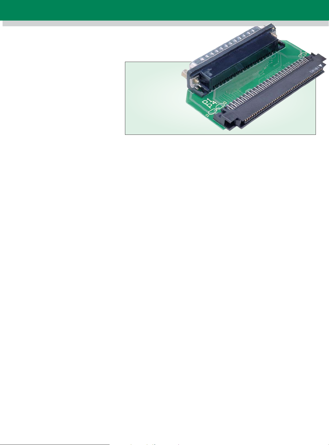
boards can be operated synchronously.
The OMB-DAQBOARD-2000 Series
provides all I/O signals on one
100-pin connector. The following
adaptor options make it easy for the
user to attach signals and
expansion options to the
OMB-DAQBOARD-2000 Series.
OMB-DBK200
Adaptor Board
Suitable exclusively for analog-signal
expansion, the OMB-DBK200
adaptor board contains one 100-pin
connector that connects to the
OMB-DAQBOARD-2000 Series via
the OMB-CA-195 cable, and one
female DB37 connector that mates
directly with the P1 port of any of
the OMB-DBK analog signal
conditioning and expansion options.
This is the most convenient way to
add analog expansion options if
access to the OMB-DAQBOARD-2000
Series digital I/O or frequency
signals is not required. Access to
P1 analog signals is also possible
via included female-mating
solder-lug connectors or optional
OMB-CA-37-x or OMB-CA-37-xT
expansion cables.
D1-5
Page 6

System Configuration Examples
OMB-DBK82 OMB-DBK16 OMB-DBK15
14-channel high-accuracy
thermocouple
expansion card
OMB-DBK60
enclosure with
OMB-DBK82,
OMB-DBK16
and OMB-DBK15
analog expansion
cards installed;
optional rackmount bracket
OMB-DBK602, $124, OMB-DBK604,
$113, OMB-DBK605, $103,
termination panels installed
2-channel strain
gage card
16-channel universal
current/voltage input
card
CA-195
P4
CA-195
P4 P1
OMBDAQBOARD2001
The OMB-DBK200, $39, adaptor mates directly with
analog OMB-DBK signal conditioning options
CA-195
OMBDAQBOARD2001
OMB-DBK201
Adaptor
P4
P4 P1
CA-195
OMB-DBK200
Adaptor
P3
P2
OMB-DBK81
T/C/mV card with
screw-terminal
connect
Frequency I/O
CA-113
Analog I/O
Digital I/O
P1
D1
ANALOG INPUT AND
MULTI-FUNCTION CARDS
Industrial rack-mount PC with
OMB-DAQBOARD-2001 board installed
CA-37-1 (8)
Desktop PC with
OMB-DAQBOARD-2001,
$1149 (computer not
included)
CA-195
P4
OMB-DBK202
Adaptor
P2
P3
OMBDAQBOARD
-2001
The OMB-DBK202, $199, or OMB-DBK206, $249,
(P1, P2, P3) adaptor with screw-terminal connectors
OMB-DBK207, $245,
(up to 16) signal
conditioning and
expansion boards
for 5B-compatible
I/O modules; analog
and digital
expansion; mounted
using Rack3
OMB-DBK206, $249,
screw-terminal
adpator board
OMB-DBK208, $219
(up to 8) signal
conditioning and
expansion boards for
OPTO-22 compatible
solid-state-relay (SSR)
modules; analog and
digital expansion;
mounted using Rack3
NEMA enclosure with OMB-DBK207 (16),
OMB-DBK206 (1), and OMB-DBK208 (8)
D1-6
Page 7
OMB-DBK209,
$59, shown
smaller than
actual size.
OMB-DBK209,
$59, shown
smaller than
actual size.
OMB-DBK201 and OMBDBK209 Adaptor Boards
For both analog and digital
expansion, the OMB-DBK201
adaptor board mates with the
OMB-DAQBOARD-2000 Series
via a 1 m (3') OMB-CA-195 cable.
The OMB-DBK209 provides 3 male
DB37 connectors, divided into P1
analog input, P2 digital
I/O, and P3 analog output and
counter/timer I/O. Each port
on the OMB-DBK201 connects to
OMB-DBK expansion options via
an optional OMB-CA-37-x or
OMB-CA-37-xT expansion cable.
Alternatively, users can solder wires
to the included DB37 female-mating
solder-lug connectors, or custom
make their own cables that are
terminated with a female DB37. An
optional 1.8 m (6') cable is available
that contains a mating female DB37
connector at one end, and is
unterminated at the other end
(OMB-CA-113). The OMB-DBK209
is identical in function to the OMBDBK201 but is snap-track (DIN-rail),
and rack-mountable with optional
mounting kits.
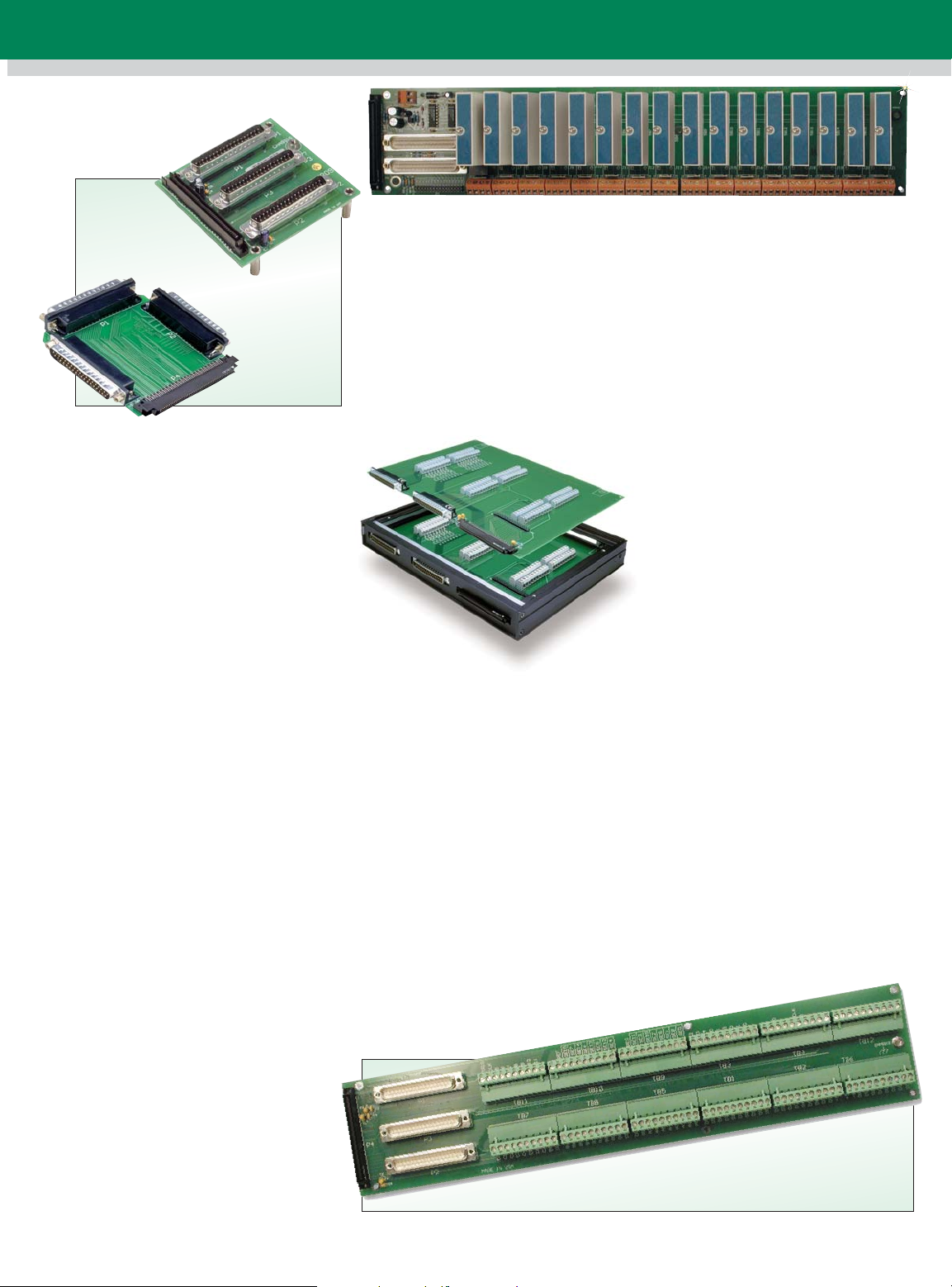
OMB-DBK202
and OMB-DBK203 ScrewTerminal Adaptor Board
The OMB-DBK202 screw-terminal
board provides convenient
screw-terminal access to all signals
from the OMB-DAQBOARD-2000
Series. Divided into 3 ports (P1, P2,
and P3), the OMB-DBK202 also
provides another way to access
signals. There are male DB37
connectors on P1 and P2, and an
adaptor cable (OMB-CA-60) can
be used to connect to the P3
header for connection to DBK signal
conditioning and expansion options.
OMB-DBK207, $249, shown smaller than actual size
Mounting holes in the OMB-DBK202
permit it to be easily screw-mounted
into a user-provided enclosure. The
OMB-DBK203 is identical to the
OMB-DBK202, except that it is
housed in a shielded metal enclosure,
which easily mounts to other
OMB-DBK signal conditioning and
expansion modules. Optional
fastener panels are available for
attaching other OMB-DBK modules.
OMB-DBK202, $199, and OMB-DBK203,
$299, shown smaller than actual size.
OMB-DBK206 ScrewTerminal Adaptor Board
Similar in function to the
OMB-DBK202, but designed for
mounting in 19-inch enclosures,
the OMB-DBK206 features three
vertically mounted straight male
DB37 connectors for analog and
digital channel expansion (P1
analog I/O, P2 digital I/O, and P3
digital and counter-timer, plus
analog output). Two rows of
removable screw terminals provide
convenient access to all
OMB-DAQBOARD-2000 Series
I/O-signals (10-22 AWG wire). It
mates with the OMB-DAQBOARD-2000
Series via a 1 m (3')
OMB-CA-195 cable, and each port
(P1, P2, and P3) connects to DBK
signal conditioning and expansion
options via optional OMB-CA-37-x
cable(s). The standard OMB-DBK206
can be panel mounted, but it also is
DIN-rail mountable and rack-mountable
with optional mounting kits.
OMB-DBK207
and OMB-DBK207/CJC
Multiplexing Isolated
Analog Input Board
The OMB-DBK207 provides sockets
for 16 channels of isolated analog
input when populated with industrystandard 5B-style or compatible
signal conditioning modules. Each
channel features screw terminals
and sockets for current conversion
resistors (supplied with 5B current
input modules). The OMB-DBK207/CJC
features added cold-junction
compensation per channel for
thermocouple-based measurements.
Multiplexing is built-in, allowing up
to 16 OMB-DBK207 boards to be
directly connected to one
OMB-DAQBOARD-2000 Series
board for a total signal capacity
of 256 isolated analog inputs.
The 100-pin P4 connector on the
OMB-DBK207 attaches directly
to the OMB-DAQBOARD-2000
(via OMB-CA-195 cable). Two DB37
connectors permit daisy chaining to
other OMB-DBK207 boards, and to
any of the other OMB-DBK analog
signal conditioning boards and
modules. The OMB-DBK207/CJC
and the OMB-DBK207 can be rack
or snap-track mounted with optional
mounting kits.
OMB-DBK206, $249,
shown smaller than
actual size.
D1-7
Page 8

OMB-DBK208
Multiplexing—Isolated
Digital I/O Board
The OMB-DBK208 provides
sockets for 16 channels of isolated
digital I/O when populated with
industry-standard Opto-22 style or
compatible solid-state-relay modules.
Each socket also features screw
terminals and an LED to indicate
logic status. The 16 digital I/O can
be jumper configured as either
inputs or outputs in 8-channel groups.
Multiplexing is built-in,
allowing up to 16 OMB-DBK208
boards to be
OMB-DAQBOARD-2000
board, for a total signal capacity of
256 isolated digital I/O channels.
On-board logic ensures that outputs
are disabled during power-up and
by a CPU reset. Also included is the
ability to choose whether outputs
are “off” or in the “last known state”
when loss of external power occurs.
The 100-pin P4 connector on the
OMB-DBK208 attaches directly to
a OMB-DAQBOARD/2000 Series
board (via OMB-CA-195 cable),
while 2 DB37 connectors permit
daisy chaining to other OMB-DBK208
boards and to any of the other
OMB-DBK digital boards and modules.
connected to one
Series
OMB-DBK208, $219,
shown smaller than
actual size.
Accuracy**
One Year, 0 to 35°C (% Reading + % Range)
Voltage Range* Absolute
0 to 10 V 0.015 + 0.005
0 to 5 V 0.015 + 0.005
0 to 2.5 V 0.015 + 0.005
0 to 1.25 V 0.015 + 0.008
0 to 0.625 V 0.015 + 0.008
0 to 0.3125 V 0.015 + 0.008
-10 to 10 V 0.015 + 0.005
-5 to 5 V 0.015 + 0.005
-2.5 to 2.5 V 0.015 + 0.005
-1.25 to 1.25 V 0.015 + 0.005
-0.625 to 0.625 V 0.015 + 0.008
-0.3125 to 0.3125 V 0.015 + 0.008
-0.156 to 0.156 V 0.02 + 0.008
* Specifications assume differential-input single-channel scan, 200 kHz scan rate, unfiltered.
** Accuracy specification is exclusive of noise.
D1
ANALOG INPUT AND
MULTI-FUNCTION CARDS
DAQVIEW Software
The DAQVIEW software allows the
user to verify signal connections,
acquire and save data to disk, and
graphically view real-time data within
moments of installing a system.
Easily set up all hardware,
acquisition, and display parameters
without programming, via a simple,
spreadsheet-style screen. The
software is a full-featured
and display application
all the functionality needed for many
data logging applications.
acquisition
that provides
Specifications
GENERAL (ALL BOARDS)
Power Consumption
(per Board): 3.5 W (up to 10 W
with external accessories)
Power Available for External
Signal Conditioning and
Expansion Options: 5 V @ 1 A
(all boards); ±15 V @ 75 mA each
(except for 2002)
Operating Temperature:
0 to 60°C (32 to 140°F)
Vibration: MIL STD 810E
Signal I/O Connector: 100-pin
high-density edge-type carries all
analog and digital I/O signals
Dimensions:
165 W x 15 D x 108 mm H
(6.5 x 0.6 x 4.2")
ANALOG INPUTS
(2000, 2001 and 2005) Channels:
16 single-ended or 8 differential,
programmable on a per-channel
basis as single-ended or differential
and unipolar or bipolar
D1-8
Expansion: Up to 256 channels per
board (4 boards per PC), without
degradation in maximum
channel-to-channel scan rate
(5 µs/channel)
Bandwidth: 500 kHz
Settling Time: 5 µs to 1 LSB
for full scale step
Maximum Input Voltage: ±11 V
relative to analog common
Overvoltage Protection: ±35 V
Ranges: Software or sequencer
selectable on a per-channel basis
A/D SPECIFICATIONS
(2000, 2001 and 2005)
Type: Successive approximation
Resolution: 16-bit
Conversion Time: 5 µs
Maximum Sample Rate: 200 kHz
Non-Linearity (Integral): ±1 LSB
Non-Linearity (Differential):
No missing codes
Page 9
INPUT SEQUENCER
(2000, 2001, 2002, 2004 and 2005)
Analog, digital and counter inputs
can be scanned synchronously,
based on either an internal
programmable timer or an external
clock source. Analog and digital
outputs can be synchronized to
either of these clocks.
Scan Clock Sources: 2
1. Internal, programmable from 5 µs
to 5.96 hours in 5 µs steps
2. External, TTL-level input up to
200 kHz max
Programmable Parameters
per Scan: Channel (random order),
gain, unipolar/bipolar
Depth: 512 location
On-Board Channel-to-Channel
Scan Rate: 5 or 10 µs per channel,
programmable
Expansion Channel Scan Rate:
5 or 10 µs per channel,
programmable
EXTERNAL ACQUISITION SCAN
CLOCK INPUT
(2000, 2001 and 2005)
Maximum Rate:
200 kHz
Clock Signal Range: 0 to 5 V
Minimum Pulse Width:
50 ns high, 50 ns low
Triggering
Trigger Sources: 6, individually
selectable for starting and stopping
an acquisition. Stop acquisition can
occur on a different trigger source
than start acquisition, and can be
triggered via modes 2, 4, 5 or 6.
Pre-trigger is supported with fixed or
variable pre-trigger periods.
1. Single-channel analog hardware
trigger latency: 5 µs max
(2000, 2001 and 2005)
2. Single-channel analog software
trigger latency: one scan period max
(2000, 2001 and 2005)
3. Single-channel digital trigger
latency: 5 µs max
(2000, 2001, 2002, 2004 and 2005)
4. Digital pattern triggering
latency: one scan period max
(2000, 2001, 2002, 2004 and 2005)
5. Counter/totalizer triggering
(2000, 2001, 2002, 2004 and 2005)
latency: one scan period, max
(all boards)
6. Software triggering (all boards)
trigger can be initiated under
program control.
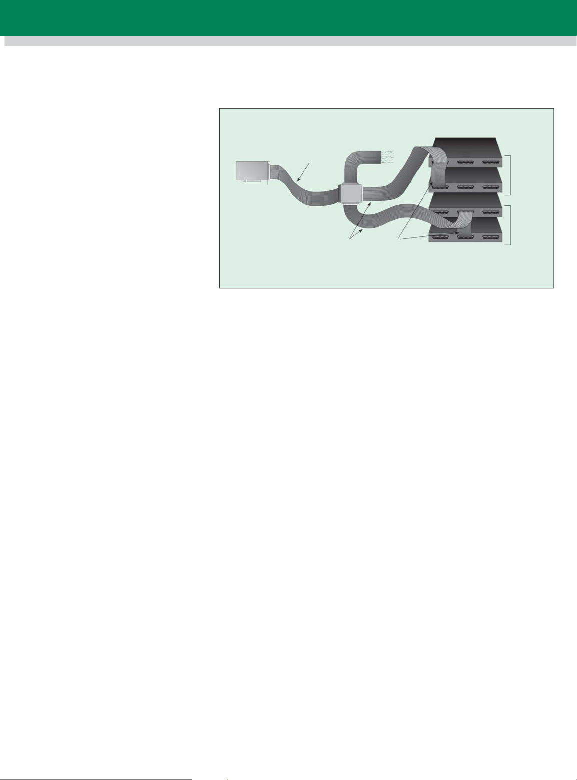
OMB-DAQBOARD-2001
OMB-CA-113
OMB-CA-195
P3
P4 P1
P2
OMB-CA-37-3T
The OMB-DBK201, $49 adaptor with analog and digital DBK signal
conditioning and expansion modules terminal connectors
ANALOG OUTPUTS
(2000, 2001 and 2004)
The 2 or 4 analog output channels
are updated synchronously relative
to scanned inputs, and clocked from
either an internal on-board clock or
an external clock source. Analog
outputs can be updated
asynchronously, independent of any
other scanning in the system. Bus
mastering DMA provides CPU and
system-independent data transfers,
ensuring accurate outputs
independent of other system
activities. Streaming from disk or
memory is supported, allowing
continuous, nearly infinite-length,
waveform outputs (limited only by
available PC system resources).
Channels: 2 (2000); 4 (2001
and 2004)
Resolution: 16-bit
Output Voltage Range: ±10 V
Clock Sources: 4, programmable
1. On-board D/A clock, independent
of scanning input clock
2. On-board scanning input clock
(2000, 2001 & 2004 only)
3. External D/A input clock,
independent of external scanning
input clock
4. External scanning input clock
(2000, 2001 and 2004 only)
DIGITAL I/O
(2000, 2001, 2002, 2004 and 2005)
Channels: 40, expandable up to
208 with OMB-DBK options
Input Scanning Modes:
2, programmable
1. Asynchronous, under program
control at any time
2. Synchronous with input scanning
Analog
DBK
Module
Digital
DBK
Module
OMB-CA-37-1T
Ports: 3 x 8-bit (82C55 emulation),
and 1 x 16-bit; each port is software
programmable as input or output
Input Characteristics:
100 ≈ series, 20 pF to common
I/O Levels: TTL
Sampling/Update Rate: 200 kHz
max
Output Characteristics:
Output 12 mA per pin, 200 mA total
continuous (per bank of 40 outputs)
Pattern Generation Output
(2000, 2001, 2002, 2004 and 2005)
The P3 16-bit digital I/O port can
be configured for 16-bit pattern
generation. The pattern can be
updated synchronously with an
acquisition.
7
COUNTER
(2000, 2001, 2002, 2004 and 2005)
Counter inputs can be scanned
synchronously along with analog
and digital scanned inputs, based
either on internal programmable
timer or an external clock source.
Counter can also be read
asynchronously.
Channels: 4 x 16-bit; cascadable as
2 x 32-bit
Frequency Measurement Rate:
10 MHz max
Trigger Level: TTL
FREQUENCY/PULSE
GENERATORS
(2000, 2001, 2002, 2004 and 2005)
Channels: 2 x 16-bit
Output: 1 MHz base rate divided by
1 to 65,535 (programmable)
D1-9
Page 10
OMB-DAQBOARD-2001, $1149,
shown smaller than actual size.
Desktop PC with
OMB-DAQBOARD-2001, $1149
(computer not included)
OMB-DBK203
Adaptor
Analog
OMB-CA-195
OMB-CA-255-4T
OMB-CA-255-2T
The OMB-DBK203, $299, adaptor with screw-terminal connectors
OMB-DBK84
Digital
OMB-DBK24
Digital
OMB-DBK23
ALL MODELS AVAILABLE FOR FAST DELIVERY!
D1
ANALOG INPUT AND
MULTI-FUNCTION CARDS
To Order
(Specify Model Number)
Model No. Price Description
OMB-DAQBOARD-2001 $1149 16-bit, 2000 kHz data acquisition board for the PCI-bus with 16 analog inputs, 40 digital
OMB-DAQBOARD-2000 799 Same as OMB-DAQBOARD-2001 but with only 2 analog outputs
OMB-DAQBOARD-2005 689 Same as OMB-DAQBOARD-2001 but with no analog outputs
OMB-DAQBOARD-2004 749 Same as OMB-DAQBOARD-2001 with analog output and digital I/O only
OMB-DAQBOARD-2002 349 Same as OMB-DAQBOARD-2001 with digital I/O only (no analog I/O)
I/O, 6 counter/timers, 2 frequency generators and 4 analog waveform outputs
(no analog inputs)
Accessories
Model No. Price Description
OMB-DBK200 $39 Adaptor board for analog I/O (P1 port)
OMB-DBK202 199 Screw terminal adaptor board, P1, P2, P3
OMB-DBK203 299 Screw terminal adaptor board, P1, P2, P3, with enclosure
OMB-DBK206 249 Screw terminal adaptor board
OMB-DBK207 249 Signal conditioning board
OMB-DBK207/CJC 399 Signal conditioning board with CJC
OMB-DBK208 219 Solid state relay board
OMB-DBK209 59 DIN rail-mount adaptor board for P1, P2, P3 ports
OMB-CA-195 79 100-conductor expansion 0.9 m (3') cable
OMB-CA-195-6 89 100-conductor expansion 1.8 m (6') cable
All OMB-DAQBOARD-2000s include a CD-ROM with all documentation, including operator’s manual, DaqView Windows Software, DAQX API
library for Windows 98/2000/ME/NT for C++, Visual Basic and Delphi, and drivers for LabVIEW, TestPoint and DASYLab.
Ordering Example: OMB-DAQBOARD-2001, data acquisition board, OMB-DBK200, adaptor board, OMB-DBK11A*, screw terminal panel,
OMB-CA-195, cable, and OMEGACARE 1-year extended warranty for OMB-DAQBOARD-2001
(adds 1 year to standard 1-year warranty), $1149 + 39 + 189 + 79 + 114 = $1570.
*Refer to section H (signal conditioners) of the OMEGA
for details on all the OMB-DBK expansion options that are available for use with the OMB-DAQBOARD-2000 Series.
®
Complete Data Acquisition and Computer Interface Handbook and Encyclopedia
®
D1-10
Page 11

One Omega Drive | Stamford, CT 06907 | 1-888-TC-OMEGA (1-888-826-6342) | info@omega.com
EPG05
www.omega.com
UNITED KINGDOM
www. omega.co.uk
Manchester, England
0800-488-488
UNITED STATES
www.omega.com
1-800-TC-OMEGA
Stamford, CT.
CANADA
www.omega.ca
Laval(Quebec)
1-800-TC-OMEGA
GERMANY
www.omega.de
Deckenpfronn, Germany
0800-8266342
Karviná, Czech Republic
FRANCE
www.omega.fr
Guyancourt, France
088-466-342
CZECH REPUBLIC
www.omegaeng.cz
596-311-899
BENELUX
www.omega.nl
Amstelveen, NL
0800-099-33-44
More than 100,000 Products Available!
Temperature
Calibrators, Connectors, General Test and Measurement
Instruments, Glass Bulb Thermometers, Handheld Instruments
for Temperature Measurement, Ice Point References,
Indicating Labels, Crayons, Cements and Lacquers, Infrared
Temperature Measurement Instruments, Recorders Relative
Humidity Measurement Instruments, RTD Probes, Elements
and Assemblies, Temperature & Process Meters, Timers and
Counters, Temperature and Process Controllers and Power
Switching Devices, Thermistor Elements, Probes and
Assemblies,Thermocouples Thermowells and Head and Well
Assemblies, Transmitters, Wire
Flow and Level
Air Velocity Indicators, Doppler Flowmeters, Level
Measurement, Magnetic Flowmeters, Mass Flowmeters,
Pitot Tubes, Pumps, Rotameters, Turbine and Paddle Wheel
Flowmeters, Ultrasonic Flowmeters, Valves, Variable Area
Flowmeters, Vortex Shedding Flowmeters
pH and Conductivity
Conductivity Instrumentation, Dissolved Oxygen
Instrumentation, Environmental Instrumentation, pH
Electrodes and Instruments, Water and Soil Analysis
Instrumentation
Data Acquisition
Auto-Dialers and Alarm Monitoring Systems,
Communication Products and Converters, Data
Acquisition and Analysis Software, Data Loggers
Plug-in Cards, Signal Conditioners, USB, RS232, RS485
and Parallel Port Data Acquisition Systems, Wireless
Transmitters and Receivers
Pressure, Strain and Force
Displacement Transducers, Dynamic Measurement
Force Sensors, Instrumentation for Pressure and Strain
Measurements, Load Cells, Pressure Gauges, Pressure
Reference Section, Pressure Switches, Pressure Transducers,
Proximity Transducers, Regulators,
Strain Gages, Torque Transducers, Valves
Heaters
Band Heaters, Cartridge Heaters, Circulation Heaters,
Comfort Heaters, Controllers, Meters and Switching
Devices, Flexible Heaters, General Test and Measurement
Instruments, Heater Hook-up Wire, Heating Cable
Systems, Immersion Heaters, Process Air and Duct,
Heaters, Radiant Heaters, Strip Heaters, Tubular Heaters
click here to go to the omega.com home page
 Loading...