

Page 1
User’s Guide
Shop online at
www.omega.com
e-mail: info@omega.com
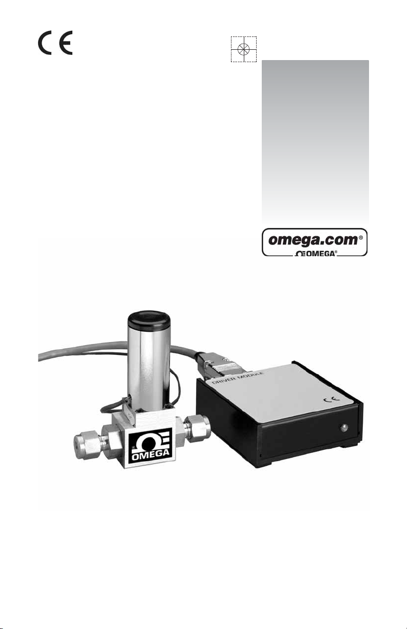
FSV10 SERIES
Solenoid Valve
Page 2
OMEGAnet®Online Service Internet e-mail
www.omega.com info@omega.com
Servicing North America:
USA: One Omega Drive, Box 4047
ISO 9001 Certified Stamford CT 06907-0047
Tel: (203) 359-1660 FAX: (203) 359-7700
e-mail: info@omega.com
Canada: 976 Bergar
Laval (Quebec) H7L 5A1
Tel: (514) 856-6928 FAX: (514) 856-6886
e-mail: info@omega.ca
For immediate technical or application assistance:
USA and Canada: Sales Service: 1-800-826-6342 / 1-800-TC-OMEGA
Customer Service: 1-800-622-2378 / 1-800-622-BEST
Engineering Service: 1-800-872-9436 / 1-800-USA-WHEN
TELEX: 996404 EASYLINK: 62968934 CABLE: OMEGA
®
®
®
Mexico: En Espan˜ ol: (001) 203-359-7803 e-mail: espanol@omega.com
FAX: (001) 203-359-7807 info@omega.com.mx
Servicing Europe:
Benelux: Postbus 8034, 1180 LA Amstelveen, The Netherlands
Czech Republic: Rude´ arm-dy 1868, 733 01 Karvin- 8
France: 11, rue Jacques Cartier, 78280 Guyancourt, France
Germany/Austria: Daimlerstrasse 26, D-75392 Deckenpfronn, Germany
United Kingdom: One Omega Drive, River Bend Technology Centre
ISO 9002 Certified Northbank, Irlam, Manchester
It is the policy of OMEGA to comply with all worldwide safety and EMC/EMI regulations that
apply. OMEGA is constantly pursuing certification of its products to the European New Approach
Directives. OMEGA will add the CE mark to every appropriate device upon certification.
The information contained in this document is believed to be correct, but OMEGA Engineering, Inc.accepts
no liability for any errors it contains, and reserves the right to alter specifications without notice.
WARNING:These products are not designed for use in, and should not be used for, patient-connected applications.
Tel: +31 (0)20 3472121 FAX: +31 (0)20 6434643
Toll Free in Benelux: 0800 0993344
e-mail: sales@omegaeng.nl
Tel: +420 (0)59 6311899 FAX: +420 (0)59 6311114
Toll Free: 0800-1-66342 e-mail: info@omegashop.cz
Tel: +33 (0)1 61 37 29 00 FAX: +33 (0)1 30 57 54 27
Toll Free in France: 0800 466 342
e-mail: sales@omega.fr
Tel: +49 (0)7056 9398-0 FAX: +49 (0)7056 9398-29
Toll Free in Germany: 0800 639 7678
e-mail: info@omega.de
M44 5BD United Kingdom
Tel: +44 (0)161 777 6611
Toll Free in United Kingdom: 0800-488-48 FAX: +44 (0)161 777 6622
e-mail: sales@omega.co.uk
Page 3

TABLE OF CONTENTS
(a) UNPACKING THE FSV10 DRIVER MODULE...................................
a.1 Inspect Package for External Damage...................................
a.2 Unpack the Valve Driver Module..............................................
a.3 Returning Merchandise for Repair..........................................
(b) INSTALLATION.............................................................................
b.1 Electrical Connections.............................................................
b.1.1 Valve Connection to FSV10...................................................
b.1.2 Input Reference Signal Connection........................................
b.1.3 TTL Signal Connection........................................................
b.1.4 Power Connection...............................................................
(c) DESCRIPTION..............................................................................
(d) SPECIFICATIONS.........................................................................
d.1 CE Compliance.......................................................................
(e) OPERATING INSTRUCTIONS......................................................
e.1 Preparation.............................................................................
e.2 Maximum Output Voltage to Valve.............................................
e.3 Set Point Reference Signal......................................................
e.4 TTL, Valve ON/OFF Control....................................................
e.5 FSV Proportionating Solenoid Valves..................................
e.5.1 FSV Preperation and Operation...............................................
e.5.2 FSV Maintenance....................................................................
1
1
1
1
2
2
3
3
3
4
4
4
5
5
5
5
6
6
7
7
10
(f) TROUBLESHOOTING...................................................................
f.1 Common Conditions................................................................
f.2 Troubleshooting Guide...............................................................
f.3 Technical Assistance.................................................................
APPENDIX 1 COMPONENT DIAGRAMS
APPENDIX 2 DIMENSIONAL DRAWINGS
APPENDIX 3 WARRANTY
®
Omega
-is a registered trademark of Omega Engineering, Inc.
®
Buna
-is a registered trademark of DuPont Dow Elastometers.
®
Kalrez
-is a registered trademark of DuPont Dow Elastomers.
TRADEMARKS
®
Neoprene
-is a registered trademark of DuPont.
®
Viton
-is a registered trademark of DuPont Dow Elastomers.
11
11
12
12
Page 4

(a) UNPACKING THE FSV10 DRIVER MODULE
a.1 Inspect Package for External Damage
Your FSV10 Solenoid Valve Driver Module was carefully packed in a sturdy cardboard carton, with anti static cushioning materials to withstand
shipping shock. Upon receipt, inspect the package for possible external
damage.In case of external damage to the package contact the shipping
company immediately.
a.2 Unpack the Valve Driver Module
Open the carton carefully from the top and inspect for any sign of concealed shipping damage. Please keep all packing and notify Omega
Customer Service of any damage.
When unpacking the instrument please make sure that you have all the
items indicated on the Packing List.Please report any shortages promptly.
a.3 Returning Merchandise for Repair
Please contact the customer service representative at 1-800-826-6342
ext. 2208 for a Return Authorization Number (AR).
It is mandatory that any equipment returned for servicing be purged and
neutralized of any dangerous contents including but not limited to toxic,
bacterially infectious, corrosive or radioactive substances.
1
Page 5
(b) INSTALLATION
Caution: Solenoid Valves or other equipment coming into contact
with gas flow should not be used for monitoring OXYGEN unless
specifically cleaned and prepared for such application.
For more information, contact Omega.
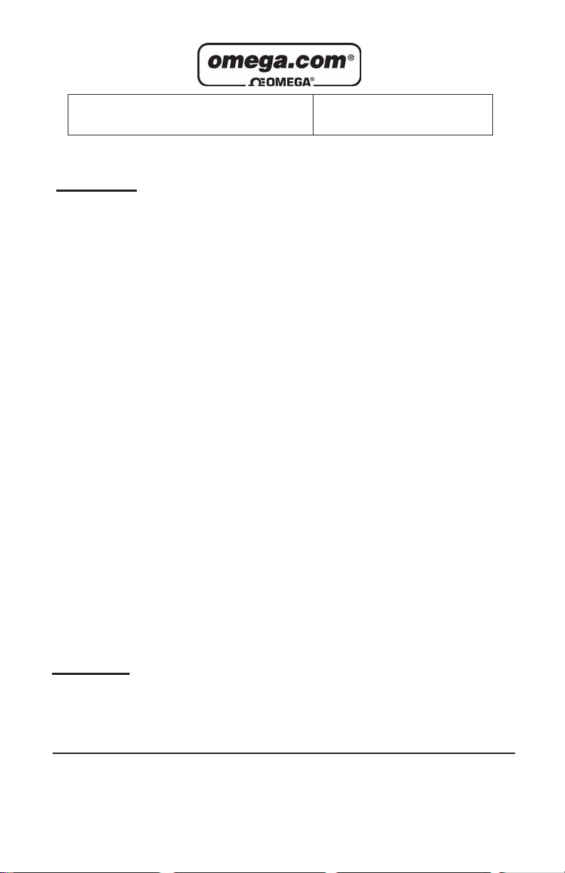
b.1 Electrical Connections
PIN FUNCTION
1 Valve, E1
2 Valve E2
3 Power supply, positive
4 Power supply, common
5 0 to 5 VDC, signal in
6 0 to 5 VDC, common
7 4 to 20 mA, signal in
8 4 to 20 mA common
9 TTL valve ON/OFF control
Figure b-1, 9 pin "D" Connector Pinouts for FSV10 Driver Module.
Important notes:
In general, "D" Connector numbering patterns are standardized. There
are, however, some connectors with nonconforming patterns and the
numbering sequence on your mating connector may or may not coincide
with the numbering sequence shown in our pin configuration table above.
It is imperative that you match the appropriate wires in accordance with
the correct sequence regardless of the particular numbers displayed on
your mating connector.
Make sure power is OFF when connecting or disconnecting any cables
in the system.
The power input is protected by a 1600mA M (medium time lag) resettable fuse. If a shor ting condition or polarity reversal occurs, the fuse will
cut power to the valve driver circuit. Disconnect the power to the unit,
remove the faulty condition, and reconnect the power.The fuse will reset
once the faulty condition has been removed.
Use of the FSV10 valve driver in a manner other than that specified in this
manual or in writing from Omega, may impair the protection provided by
the equipment.
2
Page 6
b.1.1 Valve Connection to FSV10
Connect the two valve solenoid lead wires (E1 and E2) to pins 1 and 2 of
the 9 pin "D" connector.There is no polarity on these connections.
b.1.2 Input Reference Signal Connection
Connect the desired analog reference signal input (0 to 5 VDC or 4 to 20
mA) to the appropriate pin locations on the 9 pin "D" connector of the
FSV10.The FSV10 will recognize automatically which signal is being provided.If both are connected, the FSV10 will give priority to the 4 to 20 mA
signal when that signal is greater than 2 mA.
a) When using the 0 to 5 VDC reference signal, connect the POSITIVE
side of the reference to pin 5, and the NEGATIVE (ground) to pin 6
on the 9 pin "D" connector.
b) When using the 4 to 20 mA reference signal, connect the POSITIVE
side of the reference to pin 7, and the NEGATIVE (ground) to pin 8
on the 9 pin "D" connector.
For optional RS232 or IEEE488 interfaces please contact Omega.
The NEGATIVE (ground) side of the reference signal inputs is
internally connected on the printed circuit board to power ground.
b.1.3 TTL Signal Connection
The TTL v alve ON/OFF control f eature is not required for the de vice to function. Use of this SAFETY feature allows for complete de energizing of the
solenoid valve to help ensure valve closure. If this feature is not used, a
continuous supply of nominal power will be supplied to the solenoid valve.
When left unconnected on the 9 pin "D" connector, the device will default
to the "HIGH" setting in accordance with the selected position of the
jumper.The factory default setting is LOW (0 VDC) = OFF and HIGH (5
VDC) = ON.
Jumper Setting (position) TTL LOW (0 VDC) TTL HIGH (5 VDC)
4 OFF ON
5 ON OFF
Table I TTL Signal Selection
3
Page 7

To reverse this configuration, remove the square cap on the back of the
FSV10 (see Figure e-1). The 4th and 5th position determines the TTL
logic configuration. The factory default setting is set with the jumper on
position 4. Moving this jumper to position 5 will yield the reverse configuration [LOW (0 VDC) = ON and HIGH (5 VDC) = OFF] (see Table I).
Always make sure that only one jumper is ever applied at any
given time to either position 4 or 5. Connecting both at the same
time may result in damage to the electronics, and improper control.
b.1.4 Power Connection
With the DC power supply source OFF, connect the power to the DC
power jack OR the 9 pin "D" connector.
DO NOT CONNECT POWER TO BOTH CONNECTION POINTS
AT THE SAME TIME.This may result in permanent damage to
the power supplies and the FSV10.
(c) DESCRIPTION
The FSV10 solenoid driver module is designed to regulate the power
supplied to the proportional solenoid valve based on a reference signal.
A 0 to 5 VDC or 4 to 20 mA analog set point signal input is used as a reference to proportionally control the output power to the valve.By increasing or decreasing this analog reference signal, the valve volume of gases
or liquids processed increases or decreases respectively.
(d) SPECIFICATIONS
Environmental (per IEC 664): Installation Level II; Pollution Degree II.
Connection: 9 pin male "D" connector for input/output signals.
Power Input: +12 to 30 VDC; 1A @ 12 VDC, 0.5A @ 24 VDC via 9 pin
"D" connector or DC power jack (center positive).
Input Signal: AUTO SELECT feature allows circuit to recognize which
analog input reference (0 to 5 VDC or 4 to 20 mA) signal is received.
For optional RS232 or IEEE488 interfaces please contact Omega.
TTL ON/OFF: Jumper selectable LO W (0 VDC) OFF - HIGH (5 VDC) ON
[default setting] or reverse, to select valve ON/OFF status.
4
Page 8

Valve Output Power: Jumper selectable to +15, +22, and +29 VDC with
adjacent potentiometer to obtain "2 VDC [default setting 22 VDC]
Fuse Rating: internal resettable 1.6A fuse protects the electronics on the
power input.
Polarity Protection:internal rectifier circuit protects from reversed polar-
ity on the power input.
F
Operating Temperature: 0
C (32FF) to 50F(122FF).
d.1 CE Compliance
Any model FSV10 bearing a CE marking on it, is in compliance with the
below stated test standards currently accepted.
EMC Compliance with 89/336/EEC as amended;
Emission Standard: EN 55011:1991, Group 1, Class A
Immunity Standard: EN 55082 2:1995
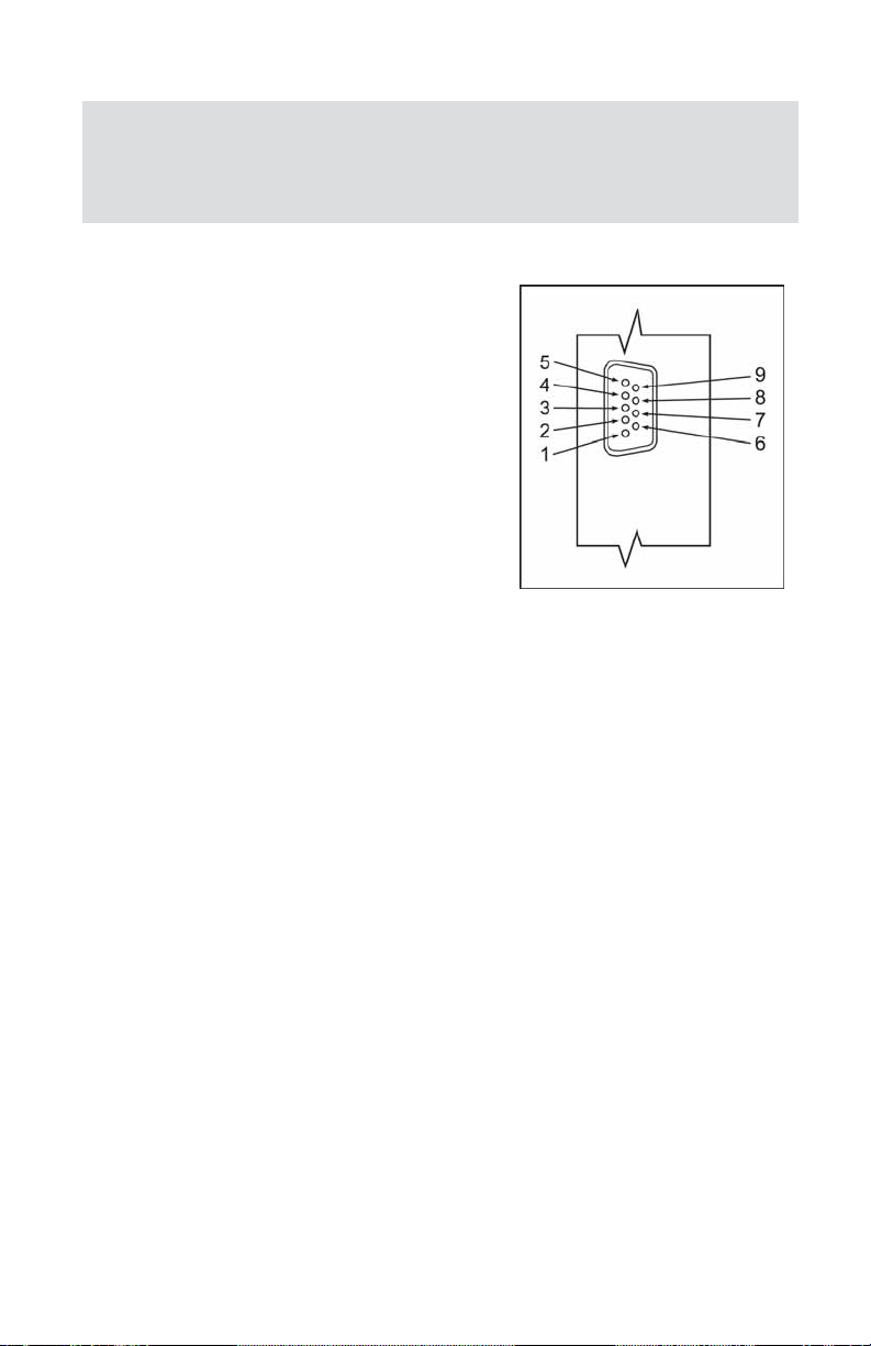
(e) OPERATING INSTRUCTIONS
1 2 3 4 5
ACCESS WINDOW
1
6
9-PIN "D"
SUB-CONNECTOR
5
9
DC POWER
JACK
CAUTION: If the valve is left in the active mode for an extended
period of time, it may become warm or even hot to the touch.
Use care in avoiding direct contact with the valve during operation.
e.1 Preparation
It is assumed that the FSV10 has been correctly installed as described in
section (b).Turn the DC power source ON. A pilot light on the front of the
FSV10 will illuminate indicating the device is active.
e.2 Maximum Output Voltage to Valve
As shown in Figure e-1, remove the square plug of the FSV10 for the
access window. Position 1, 2, and 3 on the header block deter mine the
maximum output voltage supplied to the valve. The factory default setting
is 22 VDC (position 2).
5
Page 9

Jumper Setting (position) Output V oltage to Valve (VDC)
1 15
2 22
3 29
Table II Maximum Valve Output Selection
The maximum output voltage supplied to the valve, can be set/changed
in the field. Changing this will allow for optimal use of the input reference
signal to output valve voltage based on the specific flow rate and operating pressure applied to the valve.
With the power ON, use Table II and Figure e-1 to make the appropriate
changes as necessary. (Note: This procedure may not need to be performed. It is provided as an added feature to fur ther customize your system.) Move the jumper to either position 1, 2, or 3, and use the adjacent
potentiometer [P1] to make fine adjustments to the desired output voltage.
Always make sure that only one jumper is ever applied at any
given time to either position 1, 2, or 3. Connecting two or more at
the same time may result in damage to the electronics, and
improper control.
e.3 Set Point Reference Signal
The FSV10 solenoid valve driver in conjunction with the solenoid valve
allow the user to set the flow to any desired flow rate within the range of
the particular model installed.The solenoid valve is normally closed when
no power is applied.
The set point input responds to an analog 0 to 5 VDC or 4 to 20 mA reference signal. Use this reference signal via the FSV10 valve driver to set
the flow rate of the solenoid valve.
e.4 TTL,Valve ON/OFF Control
It may, at times, be desirable to set the flow and maintain that setting while
being able to turn the flow control valve off and on again. This can be
accomplished by applying a (TTL compatible) high and low signal of +5
VDC and 0 VDC to pin 9 on the 9 pin "D" connector .The factory default configuration is set so that when 0 VDC (LOW) signal is applied, the solenoid
valve is not pow ered and theref ore will remain normally closed.Conversely,
a +5 VDC (HIGH) signal applied will allow the solenoid valve to remain
active. The solenoid valve will remain active when the VALVE OFF pin
remains "floating". (To reverse this configuration, see section b.1.3)
6
Page 10

Toggling the HIGH/LOW signal on and off will allow for activating and
deactivating the solenoid valve. Remember: If the TTL signal line is connected, the valve will only function if the appropriate logic input is applied.
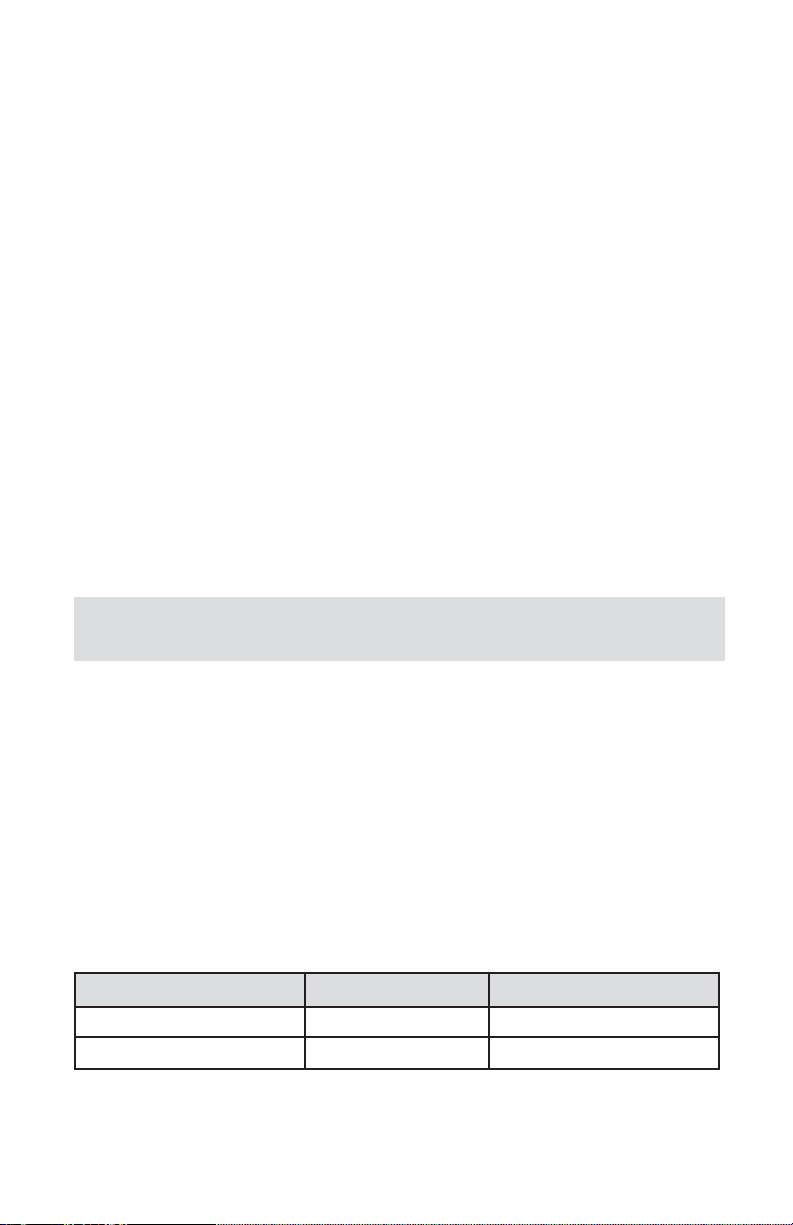
e.5 FSV Proportionating Solenoid Valves
*maximum flow
[ml / min]
MODEL
NUMBER
ORIFICE SIZE
Cv
[inch] [mm] Air Water
FSV11 0.020 0.51 0.009 3500 125
FSV12 0.040 1.02 0.033 13000 400
FSV13 0.055 1.40 0.055 21500 700
FSV14 0.063 1.60 0.068 25000 850
FSV15 0.125 3.18 0.240 100000 2873
* based on 10 psig [690 mbar] differential pressure.
e.5.1 FSV Preperation and Operation
Prior to connecting gas/liquid flow lines inspect all parts of the piping system including ferrules and fittings for dust or other contaminants. Be sure
to observe the direction of flow as indicated by the arrow on the front of
the valve when connecting the fluid flow system to be monitored.
Insert tubing into the compression fittings until the ends of the properly
sized tubing home flush against the shoulders of the fittings. Compression
fittings are to be tightened according to the manufacturer's instructions to
one and one quarter turns. Avoid over tightening.
Once installed inline with the gas or liquid to be controlled, apply a variable DC power source at the two solenoid wires to proportionally open
and close the solenoid valve (there is no polarity). The valve is set to
begin opening at approximately 5 VDC. They can also serve as "on off"
valves (valves are not guaranteed for absolute closure). Optional FSV D
DRIVER MODULE is available when use of a 0 to 5 VDC or 4 to 20 mA
reference control signal is desired. Contact Omega7 for more information.
FSV Proportionating Solenoid Valves are uniquely designed to respond
to variable power inputs (0-30 VDC) to regulate flow of liquids and/or
gases proportionately. For added safety FSV valves are normally closed
(NC) when de-energized.
7
Page 11

Flow equipment should not be used for monitoring OXYGEN unless specifically cleaned and
prepared for such application. For more information, contact Omega7.
If the valve is left in the active mode for an extended period of time, it may become warm or
even hot to the touch. Use care in avoiding direct contact with the valve during operation.
To protect servicing personnel it is mandatory that any instrument being serviced is completely
purged and neutralized of toxic, bacteriologically infected, corrosive or radioactive contents.
Use of the FSV valve in a manner other than that specified in this instruction sheet, may impair
the protection provided by the equipment.
ADJUST.
SCREW
O-RING
COMPRESSION
NUT
SPRING
SPIRAL SPRING
GUARD
ASSEMBLY
CORE
SPIDER
SPRING
STEM
SEAT-VITON
INSERT
4-40
O-RING
SOCKET
SCREW
ORIFICE
VALV E
BODY
O-RING
BLOCK
05-19-2006
Omega7 reserves the right to change designs and dimensions at its sole discretion at any time without
notice. For certified dimensions please contact Omega7.
8
Page 12

pressure drop
9
Page 13

SPECIFICATIONS
POWER INPUT:
MAXIMUM CURRENT REQUIRED: 400 mA.
ELECTRICAL CONNECTION: male spade connectors.
TYPE OF OPERATION: normally closed (nc).
CONNECTIONS:
DIMENSIONS:
WETTED MATERIALS:
MAXIMUM PRESSURE:
MAXIMUM DIFFERENTIAL PRESSURE:
LEAK INTEGRITY: 1 X 10⁻⁹scc / sec Helium.
FLUID TEMPERATURE: 14FF to 122FF (-10FC to 50FC).
MAXIMUM TEMPERATURE (TYPICAL):
ENVIRONMENTAL (PER IEC 664):
0 to 30 VDC.
1/4 inch compression fittings, optional 1/8
inch and 3/8 inch.
3.55 inch (90.2mm) high x 3.25 inch
(82.6mm) long (with fittings) x 1.00 inch
(25.4mm) deep.
types 316 and 416 stainless steel,
VITON7 O-rings; BUNA-N7, NEOPRENE7 or
KALREZ7 O-rings are optional.
500 psig (3448 kPa).
50 psid (345 kPa).
174FF (79FC) inside, 130FF (54FC) outside
surface at 24 VDC.
installation level II; pollution degree II.
e.5.2 FSV Maintenance
The solenoid valve consists of 316 and 416 stainless steel, and VITON7
(or optional BUNA-N7, NEOPRENE7 or KALREZ7) O-rings and seals.No
regular maintenance is required except for periodic cleaning.Various corrosive gases or liquids may demand more frequent replacement of Orings and seals inside the valve. Be sure to use an elastomer material,
appropriate for your specific application. Contact Omega7 for optional
sealing materials available.
Set the FSV for maximum flow, and attempt to flush through in both directions with a clean, filtered, and neutral gas such as nitrogen. [Another
option for fully opening the valv e is to remo ve the plastic cap on top of the
valve, and turn the set screw counterclockwise until it stops]. If blockage
is not alleviated, return the unit to Omega7 for servicing.
10
Page 14

(f) TROUBLESHOOTING
f.1 Common Conditions
Your Solenoid Valve Driver Module was thoroughly checked at numerous
quality control points during and after manufacturing and assembly operations.
It was carefully packed to prevent damage during shipment. Should you
feel that the instrument is not functioning properly please check for the f ollowing common conditions first:
Are all cables connected correctly?
Is the power supply correctly selected according to requirements?
Were the connector pinouts matched properly? When interchanging with
other manufacturers' equipment, cables and connectors must be carefully wired for correct pin configurations.
11
Page 15

f.2 T roubleshooting Guide
Indication
no power to
valve
no response
to set point
valve does
not work in
"active"
position
Likely Reason
power supply off
fuse blown
power supply problem
pc board defective
inadequate gas pressure
cable or connector
malfunction
set point is too low (<2% of
full scale)
valve adjustment wrong
pc board defective
incorrect valve adjustment
pc board defect
cable or connector
malfunction
Remedy
check connection of power supply
disconnect FMA transducer from power
supply; remove the shorting condition or
check polarities; fuse resets automatically
check power supply for appropriate output
return to factory for replacement
apply appropriate gas pressure
check cables and all connections or
replace
re adjust set point
re adjust valve
return to factory for replacement
re adjust valve
return to factory for replacement
check cable and connectors or replace
valve does not
work in close
position
differential pressure too high
insufficient inlet pressure
incorrect valve adjustment
pc board defect
cable or connector
malfunction
orifice obstructed
decrease pressure to correct level
adjust appropriately
re adjust valve
return to factory for replacement
check cable and connectors or replace
disassemble to remove impediments or
return to factory
For best results it is recommended that instruments are returned to the
factory for servicing. See section a.3 for return procedures.
f.3 T echnical Assistance
Omega Engineering will provide technical assistance over the phone to
qualified repair personnel.Please call our Flow Engineering Dept. at 800872-9436 Ext.2298. Please have your Serial Number and Model Number
ready when you call.
12
Page 16

APPENDIX 1
COMPONENTS DIAGRAMS
Omega7 reserves the right to change designs and dimensions at its sole discretion at any time without
notice. For cer tified dimensions please contact Omega7.
13
Page 17

APPENDIX 2
DIMENSIONAL DRAWINGS
FSV10 SOLENOID VALVE DRIVER MODULE
Omega7 reserves the right to change designs and dimensions at its sole discretion at any time without
notice. For certified dimensions please contact Omega7.
14
Page 18

APPENDIX 2
DIMENSIONAL DRAWINGS
1.177
3.851
FLOW
1.250
3.250
6-32 UNC (2)HOLES
0.156
0.156
0.938
FSV SOLENOID VALVE
0.500
0.688
1.000
0.500
1.000
Ø 0.250
COMPRESSION
FITTING
Omega7 reserves the right to change designs and dimensions at its sole discretion at any time without
notice. For certified dimensions please contact Omega7.
15
Page 19

WARRANTY/DISCLAIMER
OMEGA ENGINEERING, INC.warrants this unit to be free of defects in materials and workmanship for a
period of 13 months from date of purchase. OMEGA’s Warranty adds an additional one (1) month grace
period to the normal one (1) year product warranty to cover handling and shipping time. This ensures
that OMEGA’s customers receive maximum coverage on each product.
If the unit malfunctions, it must be returned to the factory for evaluation. OMEGA’s Customer Service
Department will issue an Authorized Return (AR) number immediately upon phone or written request.
Upon examination by OMEGA, if the unit is found to be defective, it will be repaired or replaced at no
charge. OMEGA’s WARRANTY does not apply to defects resulting from any action of the purchaser,
including but not limited to mishandling, improper interfacing, operation outside of design limits, improper
repair, or unauthorized modification.This WARRANTY is VOID if the unit shows evidence of having been
tampered with or shows evidence of having been damaged as a result of excessive corrosion; or current,
heat, moisture or vibration; improper specification; misapplication; misuse or other operating conditions
outside of OMEGA’s control.Components which wear are not warranted, including but not limited to contact points, fuses, and triacs.
OMEGA is pleased to offer suggestions on the use of its various products. However, OMEGA neither assumes responsibility for any omissions or errors nor assumes liability for an y damages that
result from the use of its products in accordance with information pr ovided by OMEGA, either verbal or written. OMEGA warrants only that the parts manufactured by it will be as specified and free
of defects. OMEGA MAKES NO OTHER WARRANTIES OR REPRESENTATIONS OF ANY KIND
WHATSOEVER,EXPRESS OR IMPLIED,EXCEPT THAT OF TITLE, AND ALL IMPLIED WARRANTIES
INCLUDING ANY WARRANTY OF MERCHANTABILITY AND FITNESS FOR A PARTICULAR PURPOSE ARE HEREBY DISCLAIMED. LIMITATION OF LIABILITY:The remedies of purchaser set forth
herein are exclusive, and the total liability of OMEGA with respect to this order, whether based on
contract, warranty, negligence , indemnification, strict liability or otherwise, shall not exceed the
purchase price of the component upon which liability is based. In no event shall OMEGA be liable
for consequential, incidental or special damages.
CONDITIONS: Equipment sold by OMEGA is not intended to be used, nor shall it be used: (1) as a
“Basic Component” under 10 CFR 21 (NRC), used in or with any nuclear installation or activity; or (2) in
medical applications or used on humans. Should any Product(s) be used in or with any nuclear
installation or activity, medical application, used on humans, or misused in any way, OMEGA assumes
no responsibility as set forth in our basic WARRANTY/ DISCLAIMER language, and, additionally,
purchaser will indemnify OMEGA and hold OMEGA harmless from any liability or damage whatsoever
arising out of the use of the Product(s) in such a manner.
Direct all warranty and repair requests/inquiries to the OMEGA Customer Service Department. BEFORE
RETURNING ANY PRODUCT(S) TO OMEGA, PURCHASER MUST OBTAIN AN AUTHORIZED
RETURN (AR) NUMBER FROM OMEGA’S CUSTOMER SERVICE DEPARTMENT (IN ORDER TO
AVOID PROCESSING DELAYS). The assigned AR number should then be marked on the outside of the
return package and on any correspondence.
The purchaser is responsible for shipping charges, freight, insurance and proper packaging to prevent
breakage in transit.
FOR WARRANTY RETURNS, please have
the following information available BEFORE
contacting OMEGA:
1. Purchase Order number under which
the product was PURCHASED,
2. Model and serial number of the product
under warranty, and
3. Repair instructions and/or specific
problems relative to the product.
OMEGA’s policy is to make running changes, not model changes, whenever an improvement is possible.
This affords our customers the latest in technology and engineering.
OMEGA is a registered trademark of OMEGA ENGINEERING, INC.
© Copyright 2001 OMEGA ENGINEERING, INC. All rights reserved. This document may not be copied, photo-
copied, reproduced, translated, or reduced to any electronic medium or machine-readable form, in whole or in part,
without the prior written consent of OMEGA ENGINEERING, INC.
FOR NON-WARRANTY REPAIRS,
for current repair charges.Have the following
information available BEFORE contacting OMEGA:
1. Purchase Order number to cover the
COST of the repair,
2. Model and serial number of the
product, and
3. Repair instructions and/or specific problems
relative to the product.
consult OMEGA
16
RETURN REQUESTS /INQUIRIES
Page 20

Where Do I Find Everything I Need for
Process Measurement and Control?
OMEGA… Of Course!
Shop online at www.omega.com
TEMPERATURE
5
Thermocouple, RTD & Thermistor Probes, Connectors, Panels & Assemblies
5
Wire: Thermocouple, RTD & Thermistor
5
Calibrators & Ice Point References
5
Recorders, Controllers & Process Monitors
5
Infrared Pyrometers
PRESSURE, STRAIN AND FORCE
5
Transducers & Strain Gages
5
Load Cells & Pressure Gages
5
Displacement Transducers
5
Instrumentation & Accessories
FLOW/LEVEL
5
Rotameters, Gas Mass Flow Meter & Flow Computers
5
Air Velocity Indicators
5
Turbine/Paddlewheel Systems
5
Totalizers & Batch Controllers
pH/CONDUCTIVITY
5
pH Electrodes, Testers & Accessories
5
Benchtop/Laboratory Meters
5
Controllers, Calibrators, Simulators & Pumps
5
Industrial pH & Conductivity Equipment
DATA ACQUISITION
5
Data Acquisition & Engineering Software
5
Communications-Based Acquisition Systems
5
Plug-in Cards for Apple, IBM & Compatibles
5
Datalogging Systems
5
Recorders, Printers & Plotters
HEATERS
5
Heating Cable
5
Cartridge & Strip Heaters
5
Immersion & Band Heaters
5
Flexible Heaters
5
Laboratory Heaters
ENVIRONMENTAL
MONITORING AND CONTROL
5
Metering & Control Instrumentation
5
Refractometers
5
Pumps & Tubing
5
Air, Soil & Water Monitors
5
Industrial Water & Wastewater Treatment
5
pH, Conductivity & Dissolved Oxygen Instruments
M-2920/0906
 Loading...