

Page 1
omega.com
e-mail: info@omega.com
For latest product manuals:
omegamanual.info
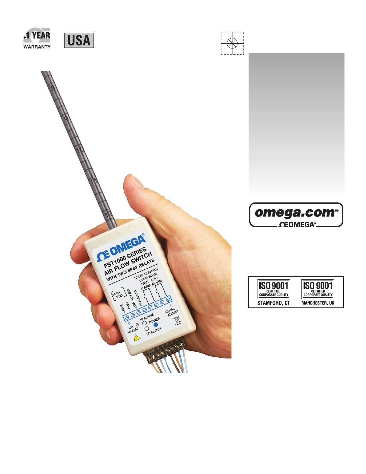
FST1000 SERIES
Air Flow Switch With Two SPST
Relay Contact Closures
MADE IN
Shop online at
User’s Guide
Page 2

Servicing North America:
U.S.A.: Omega Engineering, Inc., One Omega Drive, P.O. Box 4047
ISO 9001 Certified Stamford, CT 06907-0047 USA
Toll Free: 1-800-826-6342 TEL: (203) 359-1660
FAX: (203) 359-7700 e-mail: info@omega.com
Canada: 976 Bergar
Laval (Quebec), H7L 5A1 Canada
Toll-Free: 1-800-826-6342 TEL: (514) 856-6928
FAX: (514) 856-6886 e-mail: info@omega.ca
For immediate technical or application assistance:
U.S.A. and Canada: Sales Service: 1-800-826-6342/1-800-TC-OMEGA
®
Customer Service: 1-800-622-2378/1-800-622-BEST
®
Engineering Service: 1-800-872-9436/1-800-USA-WHEN
®
Mexico/ En Español: 001 (203) 359-7803 FAX: 001 (203) 359-7807
Latin America: info@omega.com.mx e-mail: espanol@omega.com
Servicing Europe:
Benelux: Managed by the United Kingdom Office
Toll-Free: 0800 099 3344 TEL: +31 20 347 21 21
FAX: +31 20 643 46 43 e-mail: sales@omegaeng.nl
Czech Republic: Frystatska 184
733 01 Karviná, Czech Republic
Toll-Free: 0800-1-66342 TEL: +420-59-6311899
FAX: +420-59-6311114 e-mail: info@omegashop.cz
France: Managed by the United Kingdom Office
Toll-Free: 0800 466 342 TEL: +33 (0) 161 37 29 00
FAX: +33 (0) 130 57 54 27 e-mail: sales@omega.fr
Germany/Austria: Daimlerstrasse 26
D-75392 Deckenpfronn, Germany
Toll-Free: 0800 6397678 TEL: +49 (0) 7056 9398-0
FAX: +49 (0) 7056 9398-29 e-mail: info@omega.de
United Kingdom: OMEGA Engineering Ltd.
ISO 9001 Certified One Omega Drive, River Bend Technology Centre, Northbank
Irlam, Manchester M44 5BD United Kingdom
Toll-Free: 0800-488-488 TEL: +44 (0) 161 777-6611
FAX: +44 (0) 161 777-6622 e-mail: sales@omega.co.uk
OMEGAnet®Online Service Internet e-mail
omega.com info@omega.com
It is the policy of OMEGA Engineering, Inc. to comply with all worldwide safety and EMC/EMI
regulations that apply. OMEGA is constantly pursuing certification of its products to the European New
Approach Directives. OMEGA will add the CE mark to every appropriate device upon certification.
The information contained in this document is believed to be correct, but OMEGA accepts no liability for any
errors it contains, and reserves the right to alter specifications without notice.
WARNING: These products are not designed for use in, and should not be used for, human applications.
Page 3

i
FST1000 SERIES
Air Flow Switch With Two SPST Relay Contact Closures
Table of Contents
Section Page
Section 1 - Introduction ....................................................................................... 1-1
Section 2 - Installation ......................................................................................... 2-1
Section 3 - Operations ......................................................................................... 3-1
Maintenance ..................................................................................................... 3-1
Calibration ........................................................................................................ 3-1
Section 4 - Specifications ................................................................................... 4-1
Page 4

ii
FST1000 SERIES
Air Flow Switch With Two SPST Relay Contact Closures
List of Figures
Figure Description Page
Table 1 Piping Requirement ............................................................................ 2-2
2-1 FST1000 Back Plate View ................................................................... 2-3
2-2 Typical Wiring Diagram .................................................................... 2-3
2-3 FST1000 Fixed Mount Probe, General Dimensions ....................... 2-4
2-4 FST1000 Remote Probe ...................................................................... 2-4
Page 5

Section 1 - Introduction
The FST1000 series measures air velocities up to 10,000 FPM (50.8 m/sec) and
provides two SPST relay contact closures corresponding to high and low alarm
set points. The alarm set points are adjustable from 0 to 100% of the air flow
range. This unit can be used in HVAC applications, R&D labs, exhaust/
ventilation hoods and other manufacturing processes.
The sensor is designed based on RTD elements. The air velocity is measured by
the heat loss from the RTD sensor as it cools down by the air flow. The sensor is
housed in a 1/4" OD x 12" long 304 Stainless Steel tube with inch marks for ease
of insertion depths. The sensor probe comes in two configurations:
• Fixed mount probe
• 12" long remote probe connected via 15 feet of shielded cable
The following table shows all the models of this product.
Model No. Range FPM (m/sec) Description
FST1001A 0 to 5000 (0 to 25.4) Air velocity switch,
2 relay outputs, fixed probe
FST1001R 0 to 5000 (0 to 25.4) Air velocity switch, 2 relay
outputs, remote probe
FST1002A 0 to 10,000 (0 to 50.8) Air velocity switch, 2 relay
outputs, fixed probe
FST1002R 0 to 10,000 (0 to 50.8) Air velocity switch, 2 relay
outputs, remote probe
The FST1000 air velocity switch is not explosion proof, nor is
it intrinsically safe. Do not use for flammable or hazardous
gases, or in Hazardous areas.
The FST1000 series air velocity switch is intended for use with clean air or
Nitrogen ONLY. Do not use with other gases, as it will produce an error in
measurement. In addition, air carrying dust or oil (such as found in blower/
compressor systems that utilize oil) can lead to coating of the sensor and thus
inaccurate readings.
Refer to the Maintenance section for information on cleaning the sensor. The
FST1000 is a bi-directional device, meaning the air flow in the forward or reverse
direction provides the same readings. The FST1000 can be mounted vertically or
horizontally without shift in calibration.
1-1
Introduction
1
NOTE:
Page 6

2-1
Installation
2
Section 2 – Installation
1. Remove the protective cap from the sensor tip.
2. Run a length of straight pipe before and after the flow sensor probe. The
amount of upstream straight pipe required depends on the type of obstruction
which is immediately upstream of the flow sensor. See Table 1 for specific
requirements. Downstream of the flow sensor, in all situations, run 5
diameters of straight pipe regardless of the downstream obstruction.
3. Align the sensor probe with the air flow. Make sure the air flow is
perpendicular to the sensor window. The score line on the sensor tubing is
another way of aligning the sensor to the flow stream. The score line starts
from the center of the sensor window and as a result it can be aligned
properly.
4. One way of installing the sensor probe into a flow stream is to utilize a
compression fitting such as Omega’s SSLK-14-14 stainless steel compression
fitting with PTFE ferrule, which allows adjustment of the insertion depth of
the probe.
5. Connect your wirings to the terminal block in the back of the unit. Figure 2-1
shows the back plate. The back plate has the terminal block connections, and
two potentiometer adjustments for high and low alarm set point. It also has
two red LED alarm indications, and the green LED for power indication.
Figure 2-2 shows a typical wiring diagram.
Page 7

Installation
2
2-2
Table 1. Piping Requirement
Recommended
Straight Pipe
Length "A "
T ypical Piping Remarks
Withou t
V anes
With
Va ne s
15D 15 DC losed Branch
A
A
A
A
A
A
A
A
20D 15 D
Elbow . Te e,
Branch Pipe
25D 15D Elbow , 2 planes
25D 15 D
Long-radius
bend s
30D
25D
15D
15D
Elbow
Long-radius
bend s
40D
35D
15D
15D
Elbow
Long-radius
bend s
20D 15 DC ontracting Pip e
40D 20D Expanding Pipe
Recommend Mete r
Be Installed
Upstream
Regulating,
reducing valves
Ball, check valves
Shut-of f valves
V aried Section Va lves Fittings in Tw o Planes All Fittings in Same Plan e
Note: Straight pipe length on the downstram side to be 5 pipe diameters minimum .
* D – Pipe internal diameter .
A
A
Page 8

Figure 2-1. FST1000 Back Plate View
Figure 2-2. Typical Wiring Diagram
Figure 2-3 shows the FST1000 general dimensions with fixed mount probe.
Figure 2-4 shows the FST1000 with remote probe. Both on next page.
Installation
2
2-3
HAL
ADJ
POWER
HI ALARM
LAL
ADJ
LOW ALARM
ADJUST
HIGH ALARM
ADJUST
HIGH & LOW
ALARM LEDs
LO
ALARM
12345678
15-24 VDC
POWER SUPPLY
+PWR
-PWR
+
–
DVM
+
–
LOW ALARM SET
DVM
+
–
HIGH ALARM SET
LOAD
FUSE
HIGH ALARM CONTACT
CLOSURE. NORMALLY OPEN
LOW ALARM CONTACT
CLOSURE. NORMALLY OPEN
LOAD
Fuse
1
2
3
4
5
6
7
8
Page 9

Figure 2-3. FST1000 Fixed Mount Probe, General Dimensions
Figure 2-4. FST1000 Remote Probe
Installation
2
2-4
AIR VELOCITY
SENSOR
FIXED PROBE MOUNT
1/4" OD 304 STAINLESS STEEL TUBING
WITH INCH MARKING
AIR FLOW TO BE
PERPENDICULAR TO THE
SENSOR WINDOW
AIR
FLOW
SCORE LINE FOR
FLOW ALIGNMENT
304.8
(12.0)
88.9
(3.50)
50.8 (2.0)
31.8 (1.25)
97.8
(3.85)
DIMENSIONS mm (in)
!
FST1000 SERIES
AIR FLOW SWITCH
WITH TWO SPST RELAYS
RELAY CONTACT
10A @ 24Vdc
HI ALARM
POWER
1
HAL
ADJUST
8
LAL
ADJUST
LO ALARM
15-24
VDC
+PWR
–PWR
LO ALARM SET
HI ALARM SET
LOW
ALARM
HIGH
ALARM
304.8
(12.0)
DIMENSIONS mm (in)
4.57 METERS
(15 FEET) OF
SHIELDED
FLEXIBLE CABLE
!
FST1000 SERIES
AIR FLOW SWITCH
WITH TWO SPST RELAYS
RELAY CONTACT
10A @ 24Vdc
HI ALARM
POWER
1
HAL
ADJUST
8
LAL
ADJUST
LO ALARM
15-24
VDC
+PWR
–PWR
LO ALARM SET
HI ALARM SET
LOW
ALARM
HIGH
ALARM
Page 10

3-1
Operations
3
Section 3 - Operations
The FST1000 measures the air velocity and energizes either of the two built-in
relays when the air velocity goes above or below the alarm set points. Here is the
procedure to operate this unit:
• After completing the wiring connections, use a regulated DC power supply (15
to 24 Vdc) to power the device.
• Measure the high alarm set point voltage using a DVM (Digital Volt-meter).
This voltage is measured from terminal block # 5 to # 7. The air flow range is
based on 0 to 5 Vdc. For example, if you have a 0 to 5000 FPM range unit, and
want to adjust the high alarm set point to 3500 FPM, you need to adjust the
high alarm potentiometer on the back plate (HAL ADJ) so that the DVM
measures 3.5 volts.
• Measure the low alarm set point voltage using a DVM. This voltage is
measured from terminal block # 6 to # 7. For example, if you have a 0 to 5000
FPM range unit, and want to adjust the low alarm set point to 1500 FPM, you
need to adjust the low alarm potentiometer (LAL ADJ) so that the DVM
measures 1.5 volts.
• Now you are ready to operate the unit. When the air flow goes above 3500
FPM, the high alarm relay will energize and will provide a contact closure.
When the air flow falls below 1500 FPM, the low alarm relay will energize and
will provide a contact closure. In either case, the corresponding alarm (red
LED) will also turn on.
Maintenance
Except for intermittent removal of the sensor from the line for cleaning, there is
no routine maintenance. If the sensor probe becomes coated with dust, blow the
dust away with clean air. If the sensor probe is coated with sticky material, clean
it with water or alcohol (Ethanol) using an artist’s brush.
Calibration
Each FST1000 is individually calibrated in a NIST traceable wind tunnel. For
calibration certification or calibrating to a new air flow range, the unit must be
returned back to the factory.
Page 11

Section 4 - Specifications
Air Velocity Range: 0 to 5000 FPM (0 to 25.4 m/sec),
0 to 10,000 FPM (0 to 50.8 m/sec)
Accuracy: 2% of Full Scale
Sensor Probe
Standard: 6.3 OD x 305 mm (1⁄4 OD x 12") – 304 Stainless Steel
Remote: Standard probe connected via 15' of shielded cable
Velocity Sensor: One 100 ohms RTD, Two 1000 ohms RTD
Response Time: 250 msec, 0 to 90% of final value
High Alarm Set Point: 0 to 100% adjustable, 0 to 5 Vdc
Low Alarm Set Point: 0 to 100% adjustable, 0 to 5 Vdc
Alarm Indications: Two Red LEDs, High & Low
Alarm Deadband: 5% of FS
Built-in Relays: Two 12V SPST NO relays (High & Low)
Contact Rating: 10A @ 24 Vdc, 10A @ 250 Vac
Operating Ambient Temperature
Sensor Probe: -40 to 121ºC (-40 to 250ºF)
Electronic Case: 0 to 50ºC (32 to 122ºF)
Power: 15 to 24 Vdc @ 200 mA
Power Indicator: Green LED
Dimensions: 89 H x 51 W x 32 mm D (3.5 x 2 x 1.25")
Weight: 160 g (5.6 oz)
4-1
Specifications
4
Page 12

NOTES:
4-2
FST1000 SERIES
Air Flow Switch With Two SPST Relay Contact Closures
Page 13

NOTES:
4-3
FST1000 SERIES
Air Flow Switch With Two SPST Relay Contact Closures
Page 14

4-4
NOTES:
FST1000 SERIES
Air Flow Switch With Two SPST Relay Contact Closures
Page 15

WARRANTY/DISCLAIMER
OMEGA ENGINEERING, INC. warrants this unit to be free of defects in materials and workmanship for a
period of 13 months from date of purchase. OMEGA’s WARRANTY adds an additional one (1) month
grace period to the normal one (1) year product warranty to cover handling and shipping time. This
ensures that OMEGA’s customers receive maximum coverage on each product.
If the unit malfunctions, it must be returned to the factory for evaluation. OMEGA’s Customer Service
Department will issue an Authorized Return (AR) number immediately upon phone or written request.
Upon examination by OMEGA, if the unit is found to be defective, it will be repaired or replaced at no
charge. OMEGA’s WARRANTY does not apply to defects resulting from any action of the purchaser,
including but not limited to mishandling, improper interfacing, operation outside of design limits,
improper repair, or unauthorized modification. This WARRANTY is VOID if the unit shows evidence of
having been tampered with or shows evidence of having been damaged as a result of excessive corrosion;
or current, heat, moisture or vibration; improper specification; misapplication; misuse or other operating
conditions outside of OMEGA’s control. Components in which wear is not warranted, include but are not
limited to contact points, fuses, and triacs.
OMEGA is pleased to offer suggestions on the use of its various products. However,
OMEGA neither assumes responsibility for any omissions or errors nor assumes liability for any
damages that result from the use of its products in accordance with information provided by
OMEGA, either verbal or written. OMEGA warrants only that the parts manufactured by the
company will be as specified and free of defects. OMEGA MAKES NO OTHER WARRANTIES OR
REPRESENTATIONS OF ANY KIND WHATSOEVER, EXPRESSED OR IMPLIED, EXCEPT THAT OF
TITLE, AND ALL IMPLIED WARRANTIES INCLUDING ANY WARRANTY OF MERCHANTABILITY
AND FITNESS FOR A PARTICULAR PURPOSE ARE HEREBY DISCLAIMED. LIMITATION OF
LIABILITY: The remedies of purchaser set forth herein are exclusive, and the total liability of
OMEGA with respect to this order, whether based on contract, warranty, negligence,
indemnification, strict liability or otherwise, shall not exceed the purchase price of the
component upon which liability is based. In no event shall OMEGA be liable for
consequential, incidental or special damages.
CONDITIONS: Equipment sold by OMEGA is not intended to be used, nor shall it be used: (1) as a “Basic
Component” under 10 CFR 21 (NRC), used in or with any nuclear installation or activity; or (2) in medical
applications or used on humans. Should any Product(s) be used in or with any nuclear installation or
activity, medical application, used on humans, or misused in any way, OMEGA assumes no responsibility
as set forth in our basic WARRANTY/DISCLAIMER language, and, additionally, purchaser will indemnify
OMEGA and hold OMEGA harmless from any liability or damage whatsoever arising out of the use of the
Product(s) in such a manner.
RETURN REQUESTS/INQUIRIES
Direct all warranty and repair requests/inquiries to the OMEGA Customer Service Department. BEFORE
RETURNING ANY PRODUCT(S) TO OMEGA, PURCHASER MUST OBTAIN AN AUTHORIZED RETURN
(AR) NUMBER FROM OMEGA’S CUSTOMER SERVICE DEPARTMENT (IN ORDER TO AVOID
PROCESSING DELAYS). The assigned AR number should then be marked on the outside of the return
package and on any correspondence.
The purchaser is responsible for shipping charges, freight, insurance and proper packaging to prevent
breakage in transit.
FOR WARRANTY
RETURNS, please have the
following information available BEFORE
contacting OMEGA:
1. Purchase Order number under which the product
was PURCHASED,
2. Model and serial number of the product under
warranty, and
3. Repair instructions and/or specific problems
relative to the product.
FOR NON-WARRANTY REPAIRS,
consult OMEGA
for current repair charges. Have the following
information available BEFORE contacting OMEGA:
1. Purchase Order number to cover the COST
of the repair,
2. Model and serial number of the product, and
3. Repair instructions and/or specific problems
relative to the product.
OMEGA’s policy is to make running changes, not model changes, whenever an improvement is possible. This affords
our customers the latest in technology and engineering.
OMEGA is a registered trademark of OMEGA ENGINEERING, INC.
© Copyright 2011 OMEGA ENGINEERING, INC. All rights reserved. This document may not be copied, photocopied,
reproduced, translated, or reduced to any electronic medium or machine-readable form, in whole or in part, without the
prior written consent of OMEGA ENGINEERING, INC.
Page 16

M4980/0311
Where Do I Find Everything I Need for
Process Measurement and Control?
OMEGA…Of Course!
Shop online at omega.com
SM
TEMPERATURE
䡺⻬
Thermocouple, RTD & Thermistor Probes, Connectors, Panels & Assemblies
䡺⻬
Wire: Thermocouple, RTD & Thermistor
䡺⻬
Calibrators & Ice Point References
䡺⻬
Recorders, Controllers & Process Monitors
䡺⻬
Infrared Pyrometers
PRESSURE, STRAIN AND FORCE
䡺⻬
Transducers & Strain Gages
䡺⻬
Load Cells & Pressure Gages
䡺⻬
Displacement Transducers
䡺⻬
Instrumentation & Accessories
FLOW/LEVEL
䡺⻬
Rotameters, Gas Mass Flowmeters & Flow Computers
䡺⻬
Air Velocity Indicators
䡺⻬
Turbine/Paddlewheel Systems
䡺⻬
Totalizers & Batch Controllers
pH/CONDUCTIVITY
䡺⻬
pH Electrodes, Testers & Accessories
䡺⻬
Benchtop/Laboratory Meters
䡺⻬
Controllers, Calibrators, Simulators & Pumps
䡺⻬
Industrial pH & Conductivity Equipment
DATA ACQUISITION
䡺⻬
Data Acquisition & Engineering Software
䡺⻬
Communications-Based Acquisition Systems
䡺⻬
Plug-in Cards for Apple, IBM & Compatibles
䡺⻬
Data Logging Systems
䡺⻬
Recorders, Printers & Plotters
HEATERS
䡺⻬
Heating Cable
䡺⻬
Cartridge & Strip Heaters
䡺⻬
Immersion & Band Heaters
䡺⻬
Flexible Heaters
䡺⻬
Laboratory Heaters
ENVIRONMENTAL
MONITORING AND CONTROL
䡺⻬
Metering & Control Instrumentation
䡺⻬
Refractometers
䡺⻬
Pumps & Tubing
䡺⻬
Air, Soil & Water Monitors
䡺⻬
Industrial Water & Wastewater Treatment
䡺⻬
pH, Conductivity & Dissolved Oxygen Instruments
 Loading...