

Page 1
http://www.omega.com
e-mail: info@omega.com
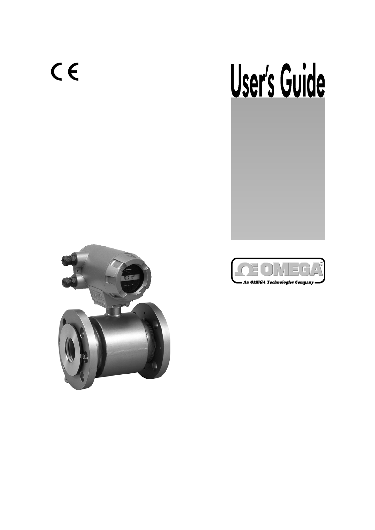
FMG-400’s
Electromagnetic Flowmeters
(Flange type)
Page 2

OMEGAnetSM On-Line Service Internet e-mail
http://www.omega.com info@omega.com
Servicing North America:
.
USA: One Omega Drive, Box 4047
ISO 9001 Certified
Canada: 976 Bergar
Stamford, CT 06907Tel: (203) 359-1660 FAX: (203) 359-7700
e-mail: info@omega.com
Laval (Quebec) H7L 5A1
Tel: (514) 856-6928 FAX: (514) 856-6886
e-mail:
canada@omage.com
0047
For immediate technical or application assistance:
USA and Canada: Sales Service: 1-800-826-6342 / 1-800-TC-OMEGA
Customer Service: 1-800-622-2378 / 1-800-622-BEST
Engineering Service:1-800-872-9436 / 1-800-USA-WHEN
TELEX: 996404 EASYLINK: 62968934 CABLE: OMEGA
Mexico and
Latin America: Tel: (95) 800-TC-OMEGASM FAX: (95) 203-359-7807
En Espanol: (203) 359-7803 e-mail: espanol@omega.com
Servicing Europe:
Benelux: Postbus 8034, 1180 LA Amstelveen, The Netherlands
Tel: (31) 20 6418405 FAX: (31) 20 6434643
Toll Free in Benelux: 06 0993344
e-mail: nl@omega.com
Czech Republic: ul. Rude armady 1868, 733 01 Karvina-Hranice, Czech Republic
Tel: 420 (69) 6311627 FAX: 420 (69) 6311114
e-mail: czech@omega.com
France: 9, rue Denis Papin, 78190 Trappes
Tel: (33) 130-621-400 FAX: (33) 130-699-120
Toll Free in France: 0800-4-06342
e-mail: france@omega.com
Germany/Austria: Daimlerstrasse 26, D-75392 Deckenpfronn, Germany
Tel: 49 (07056) 3017 FAX: 49 (07056) 8540
Toll Free in Germany: 0130 11 21 66
e-mail: germany@omega.com
United Kingdom: 25 Swannington Road, P.O. Box 7, Omega Drive,
ISO 9002 Certified Broughton Astley, Leicestershire, Irlam, Manchester,
LE9 6TU, England M44 5EX, England
Tel: 44 (1455) 285520 Tel: 44 (161) 777-6611
FAX: 44 (1455) 283912 FAX: 44 (161) 777-6622
Toll Free in England: 0800-488-488
e-mail: uk@omega.com
SM
SM
SM
It is the policy of OMEGA to comply with all worldwide safety and EMC/EMI regulations that apply. OMEGA
is constantly pursuing certification of its products to the European New Approach Directives. OMEGA will
add the CE mark to every appropriate device upon certification.
The information contained in this document is believed to be correct but OMEGA Engineering, Inc. accepts
no liability for any errors it contains, and reserves the right to alter specifications without notice.
WARNING: These products are not designed for use in, and should not be used for, patient connected
applications.
1
Page 3
SAFETY PRECAUTIONS
Safety signs and labels affixed to the product and/or described in this manual give important
information for using the product safely. They help prevent damage to property and obviate
hazards for persons using the product.
Make yourself familiar with signal words and symbols used for safety signs and labels. Then read
the safety precautions that follow to prevent an accident involving personal injury, death or
damage to property.
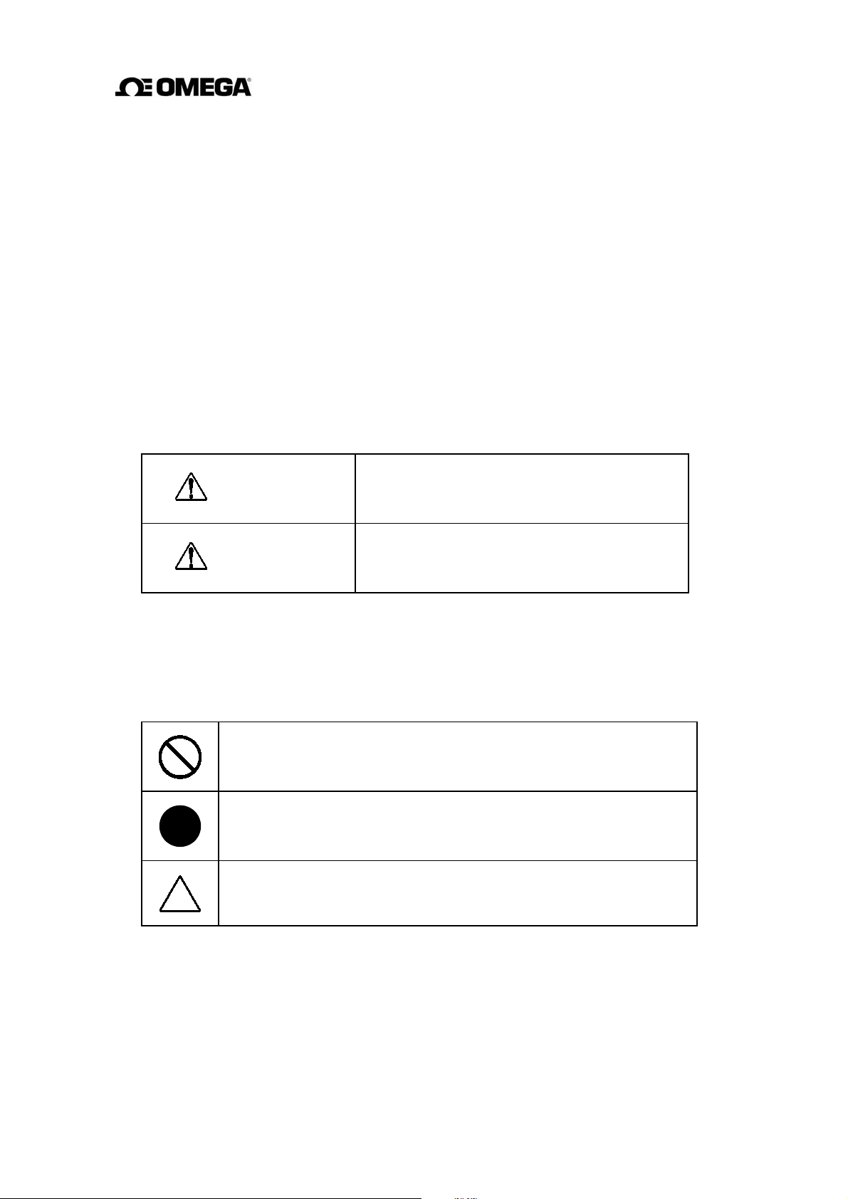
Explanation of signal words
The signal word or words are used to designate a degree or level of hazard seriousness.
The signal words used for the product described in this manual are WARNING and CAUTION.
Indicates a potentially hazardous situation which,
WARNING
CAUTION
if not avoided, could result in death or serious
injury.
Indicates a potentially hazardous situation which,
if not avoided, may result in minor to moderate
injuries or in property damage.
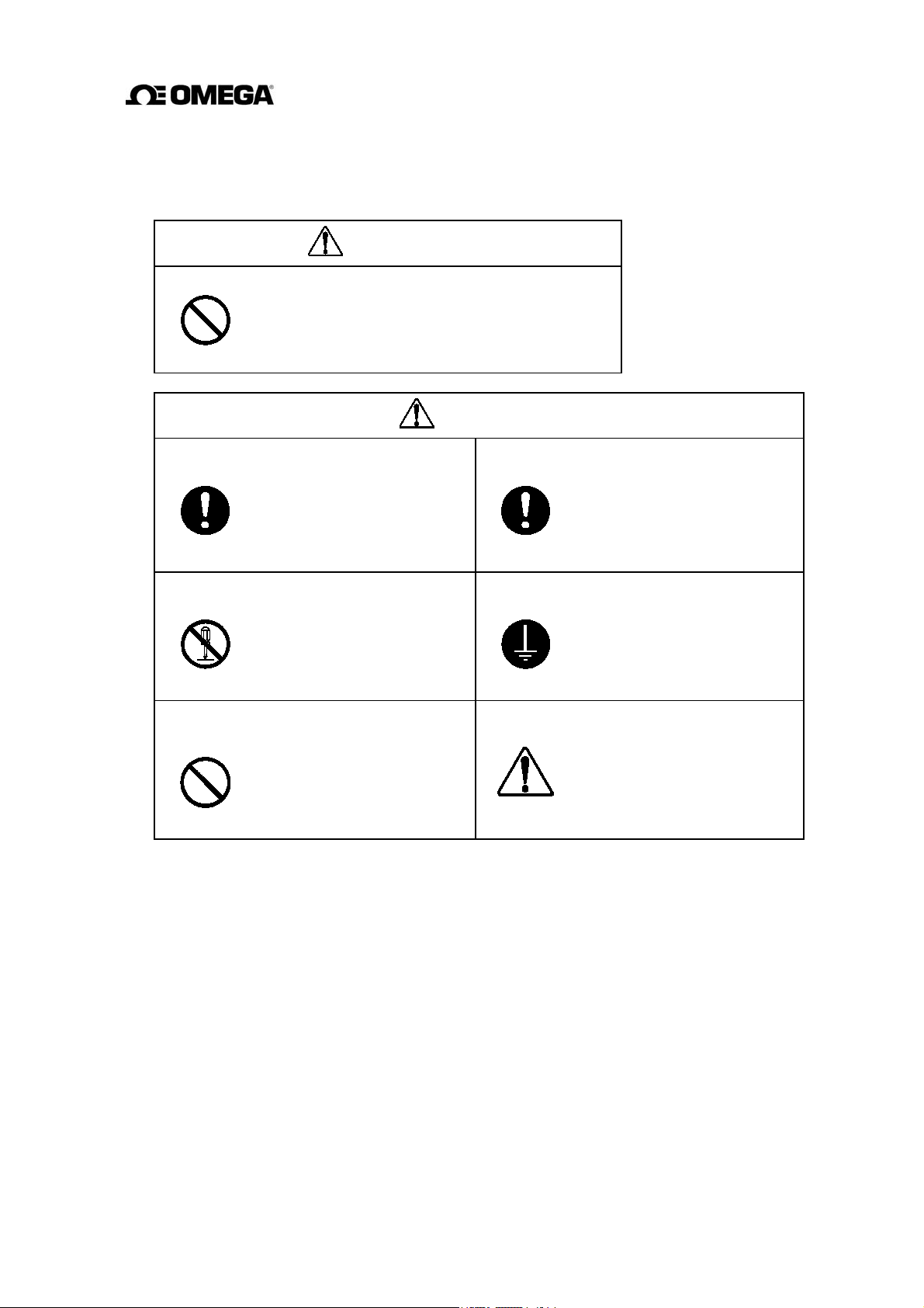
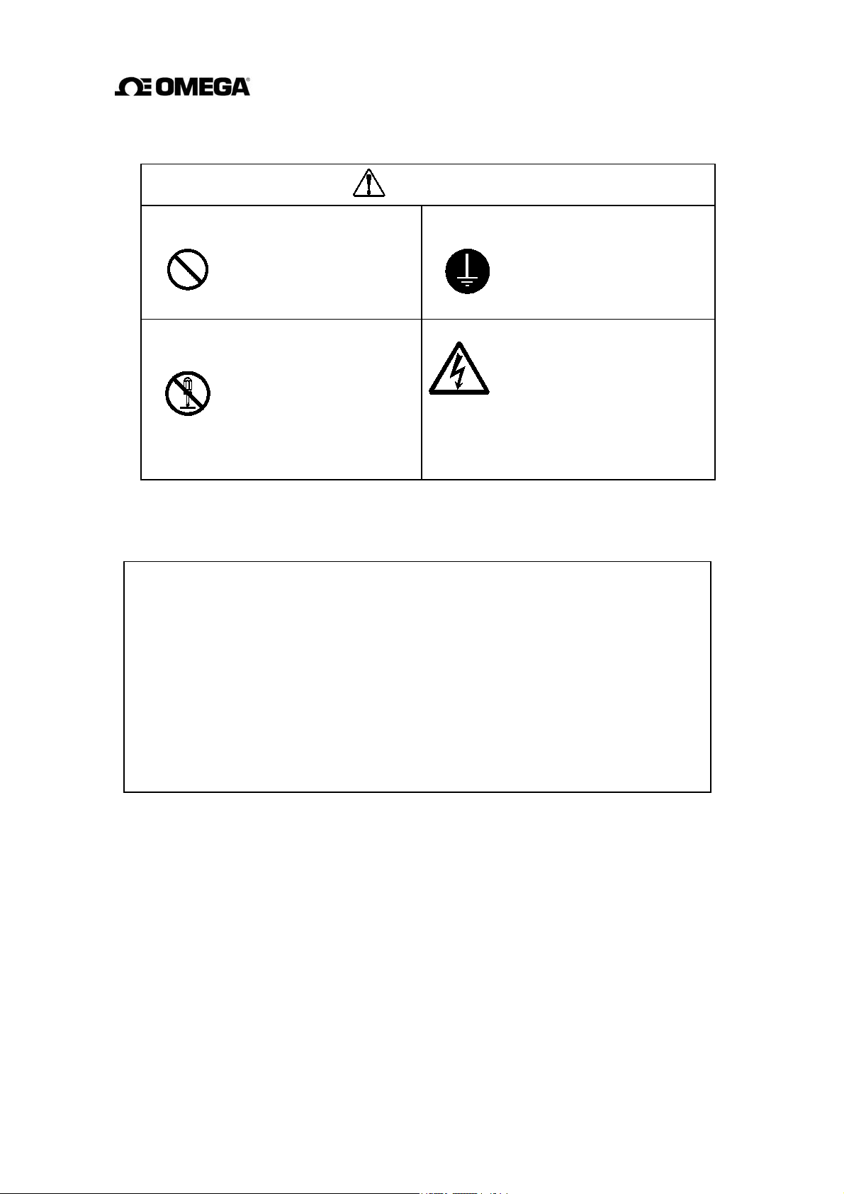
Safety symbols
The following symbols are used in safety signs and labels affixed to a product and/or in the
manual for giving safety instructions.
Indicates an action that is prohibited. Simply DON’T do this action.
The
prohibited action is indicated by a picture or text inside or next to the
circle
Indicates an action that is mandatory. DO this action.
The
mandatory action is indicated by a picture or text inside or next to the
circle.
Indicates a potential hazard. The potentially hazardous situation is
indicated by a picture or text inside or next to the triangle.
2
Page 4
SAFETY PRECAUTIONS (continued)
Safety Precautions for Installation and Wiring
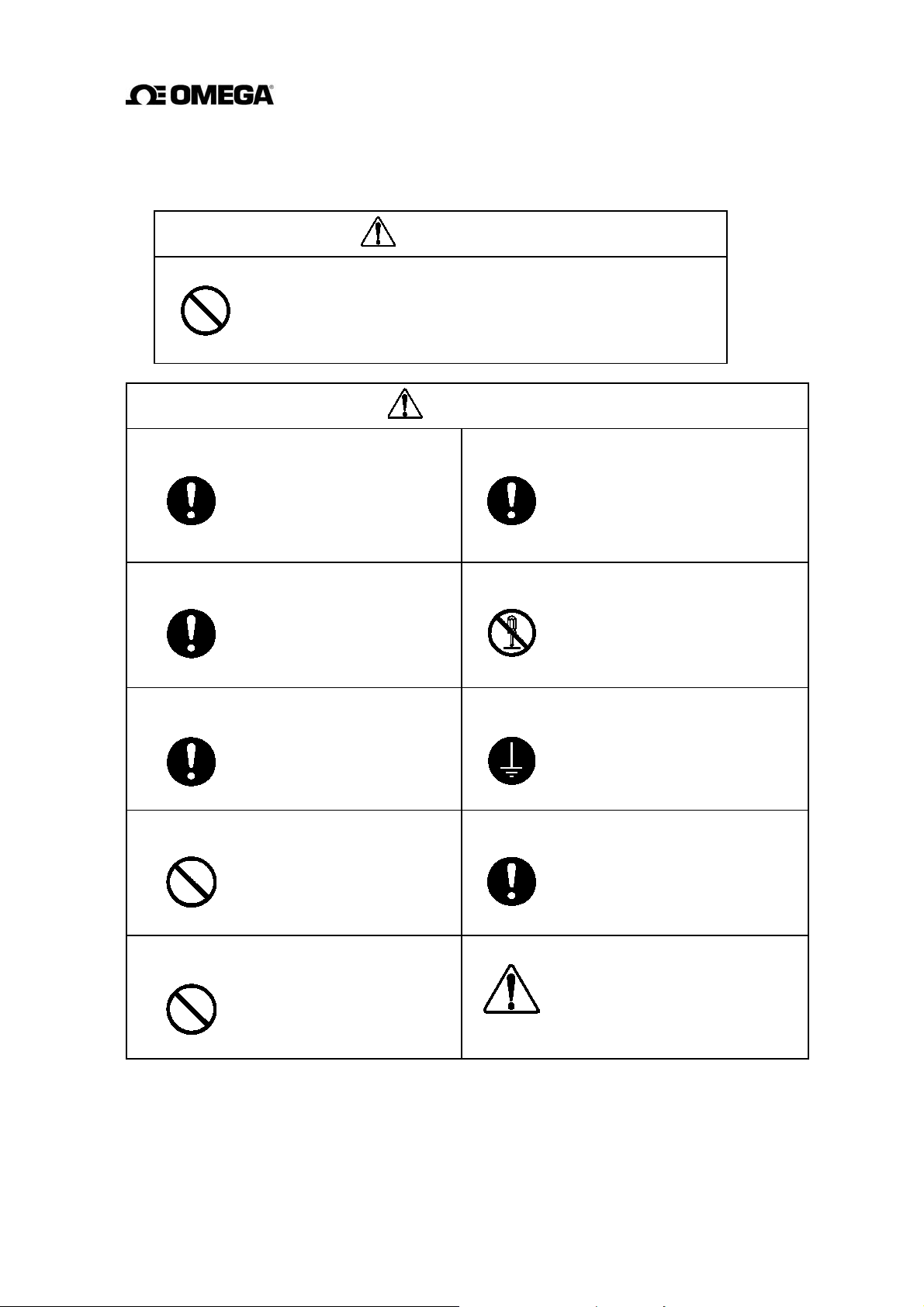
WARNING
Do not use the FMG400 Series in an explosive atmosphere.
Using this product in an explosive atmosphere can cause
explosion.
DON’T
CAUTION
Turn off main power before working on
pipes.
Working on pipes while
power is applied can cause
electric shock.
DO
Install a switch and fuse to isolate the
FMG400 Series from main power.
Power supply from main
power can cause electric
DO
Turn off main power before conducting
wiring work.
shock or circuit
breakdown.
Wiring while power is
applied can cause electric
shock.
DO
Do not conduct wiring work with bare
hands.
Remaining electric
charge even if power is
DON’T
Do not work on piping and wiring with
wet hands.
turned off can still cause
electric shock.
Wet hands may result in
electric shock.
DON’T
Use an appropriate device to carry and
install the FMG400 Series.
If this product falls to the
ground, injury, or malfunction of
DO
Do not modify or disassemble the
FMG400 Series unnecessarily.
DON’T
Ground the FMG400 Series independently
from power equipment.
DO
Use crimped terminal lugs for the terminal
board and GND terminal.
DO
or damage to the product, can be
caused.
Modifying or disassembling this
product can cause electric shock,
malfunction of or damage to
this product.
Operating this product without
grounding can cause electric
shock or malfunction.
Loose connections can cause
electric shock, fire from
excessive current or system
malfunction.
The label shown left is placed
near the terminal board for power
input.
(A
black border and symbol on
yellow triangle)
Be alert to electric shock
3
Page 5
SAFETY PRECAUTIONS (continued)
Safety Precautions for Maintenance and Inspection
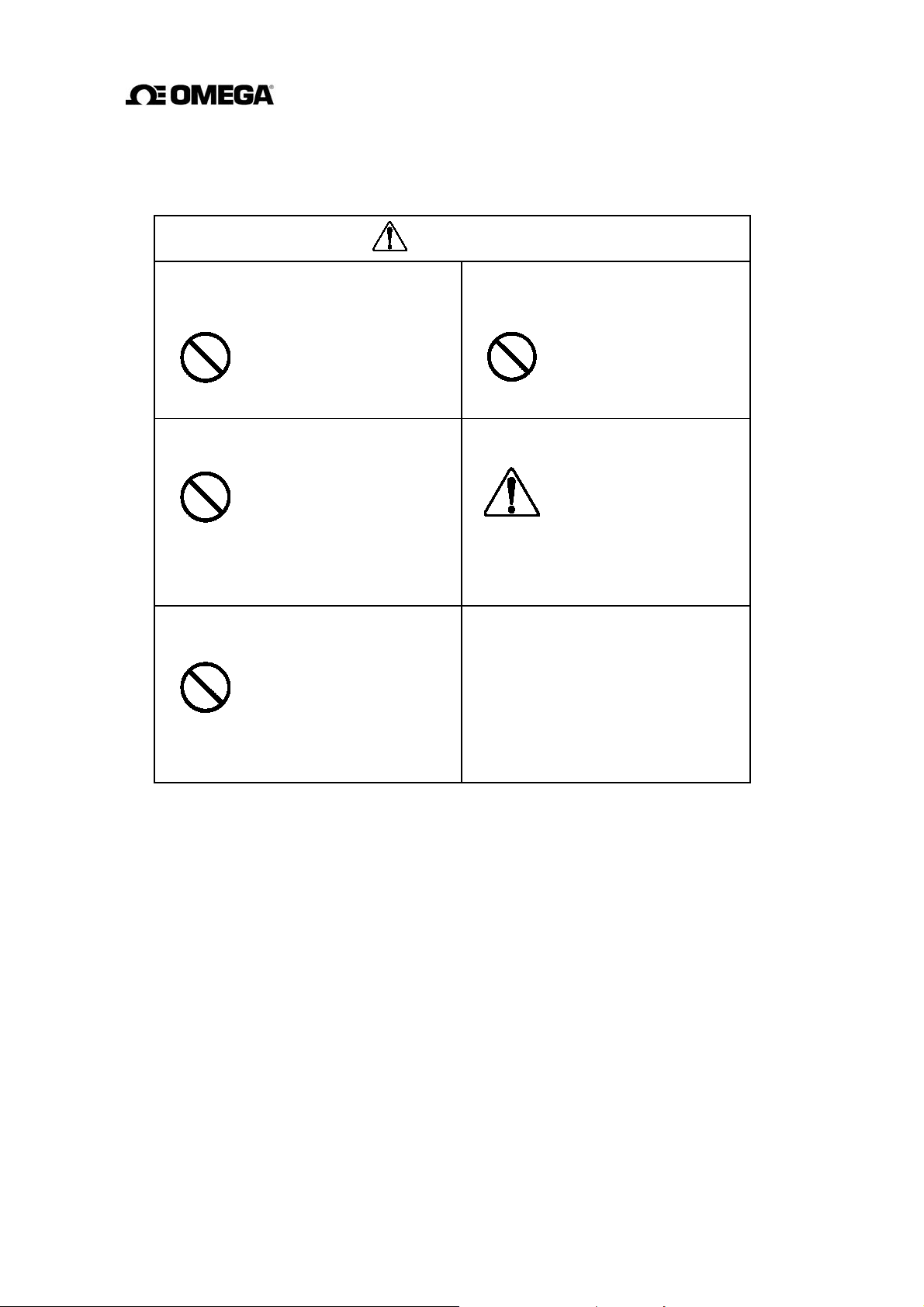
CAUTION
Do not touch the FMG400 Series
main body when high temperature
fluid is being measured.
The fluid raises the main
body temperature and can
DON’T
Do not conduct wiring work with wet
hands.
cause burns when touched.
Wet hands may result in
electric shock.
DON’T
Do not use a fuse other than the one
specified.
Using a fuse other than the
one specified can cause
DON’T
system failure, damage or
malfunction.
Do not conduct wiring work when
power is applied.
Wiring while power is
applied can cause
DON’T
Use a rated fuse as follows depending
on the power specifications.
• Fuse rating:
1A/250V for 100 to 240 V
• Dimensions:
Diameter 5.2 mm × 20 mm
electric shock.
The label shown left is
placed near the terminal
board for power input.
(A
black border and
symbol on yellow
triangle)
Be alert to electric
shock.
ac
Disclaimer
OMEGA does not accept liability for any damage or loss, material or personal, caused as a
direct or indirect result of the operation of this product in connection with, or due to, the
occurrence of any event of force majeure (including fire or earthquake) or the misuse of this
product, whether intentional or accidental.
4
Page 6

Handling Precautions
To obtain the optimum performance from the FMG400 Series flowmeter for years of
continuous operation, observe the following precautions.
(1) Do not store or install the flowmeter in:
places where there is direct sunlight. If this is unavoidable, use an appropriate
•
sunshade.
places where excessive vibration or mechanical shock occurs.
•
places where high temperature or high humidity conditions obtain.
•
places where corrosive atmospheres obtain.
•
places submerged under water.
•
To put the flowmeter temporarily on the floor, place it carefully with something to
support it so that the flowmeter will not topple over.
(2) Execute wiring securely and correctly.
(3) Seal the cable thoroughly at the cable gland so that the cable is kept airtight.
(4) Ground the flowmeter with 100 ohm or less ground resistance. Avoid a common
ground used with other equipment where earth current may flow. An independent
ground is preferable.
(5) The converter housing covers and the cable glands are tightened securely at the time
of shipment. Do not remove these covers or glands unless it is necessary to wire new
cables or replace old ones.
Otherwise, gradual deterioration of circuit isolation or
damage to this product can be caused. Tighten the covers or cable glands securely
again if they have been removed.
(6) Make sure the fluid to be measured will not freeze in the detector pipe. This can
cause damage to the detector pipe.
(7) Select appropriate wetted materials suited for the process fluid to be measured.
Otherwise, fluid leakage due to corrosion can be caused.
(8) Observe the following precautions when you open the converter housing cover:
Do not open the cover in the open air unprotected against rain or wind. This can
•
cause electric
Do not open the cover under high ambient temperature or high humidity
•
shock or cause damage to the flowmeter electronics.
conditions or in corrosive atmospheres. This can cause deterioration of system
accuracy or cause damage to the flowmeter electronics.
(9) This product may cause interference to radio and television sets if they are used near
the installation site. Use metal conduits etc. for cables to prevent this interference.
5
Page 7

Handling Precautions (continued)
(10) Radio transmitters such as transceivers or cellular phones may cause interference to
the flowmeter if they are used near the installation site. Observe the following
precautions when using them:
Do not use a transceiver whose output power is more than 5 W.
•
Move the antenna of a transceiver or a cellular phone at least 50 cm away from
•
the flowmeter and signal cables when using it. Do not use a radio transmitter or
a cellular phone near the flowmeter while it is operating online. The transmitter
or cellular phone’s output impulse noise may interfere with the flowmeter.
Do not install a radio transmitter antenna near the flowmeter and signal cables.
•
(11) For reasons of flowmeter failure, inappropriate parameters, unsuitable cable
connections or poor installation conditions, the flowmeter may not operate properly.
To prevent any of these problems causing a system failure, it is recommended that
you have preventive measures designed and installed on the flowmeter signal
receiving side.
6
Page 8

Table of Contents
SAFETY PRECAUTIONS 2
Handling Precautions 5
1. Product Inspection and Storage 9
1.1 Product Inspection 9
1.2 Storage 9
2. Overview 10
3. Names of Parts 11
4. Installation 14
4.1 Location 14
4.2 Mounting 15
4.3 Piping Connections 19
5. Wiring 23
5.1 Cables 24
5.2 External Device Connections and Grounding 24
5.3 Digital I/O Connections 26
5.4 Wiring Procedure 27
6. Operation 30
6.1 Preparatory Check 30
6.2 Zero Adjustment 31
7. LCD Display and Controls 32
7.1 Outline 32
7.2 Display Format 34
7.3 Basic Operations 36
7.4 Configuration Items Selection Table 38
8. Configuration Parameter Setting 39
8.1 Configuration Items 39
8.2 Checking or Changing Parameters 40
9. Calibration 70
9.1 Calibration Items 70
9.2 Calibration Using Converter Signal Source 71
10. Digital I/O Functions 75
10.1 Digital I/O Specifications 76
10.2 Totalizer and Pulse Output 77
10.3 Multi-range Functions 79
10.4 High and Low Limit Alarms 84
7
Page 9

10.5 Empty Pipe Alarm 86
10.6 Preset Point Output 87
10.7 Remote Zero Adjustment 89
10.8 Remote Selection of Fixed Value Output 90
10.9 Converter Failure Alarms 91
11. Self-Diagnostics and Alarms 92
11.1 Self-Diagnostics 92
11.2 Output Status for Errors and Alarms 95
12. Maintenance and Troubleshooting 96
12.1 Maintenance 96
12.2 Troubleshooting 98
13. Principle of Operation 101
14. Specifications 102
14.1 Flowmeter Specifications 102
14.2 Specification Code table 106
15. Outline Dimensions . 108
Appendix 1 . Electromagnetic Compatibility and Low Voltage Safety 110
Electromagnetic Compatibility 110
Low Voltage Safety 111
Appendix 2 . Default set value in each configuration item 112
8
Page 10

1. Product Inspection and Storage
Upon arrival of the product package, open the package and check the items contained inside. If
you do not intend to install the product soon after opening the package, store the product and
other related items in a place such as described in 1.2 below.
1.1 Product Inspection
The FMG400 Series flange type electromagnetic flowmeter is shipped in a cardboard container
filled with shock-absorbing materials. Open the package carefully and check as follows:
Make sure the following items are included in the package.
(1) Model FMG400 Series falnge type Electromagnetic Flowmeter......
(2) Instruction Manual ...............................................................
(3) Operation Guide ....................................................................
Inspect the flowmeter for indications of damage that may have occurred during shipment.
Make sure the type and specifications of the flowmeter are in accordance with the
ordered specifications.
If you cannot find the items listed above or any problem exists, contact OMEGA.
1
1
1
1.2 Storage
To store the FMG400 Series flowmeter after opening the package, select a storing place as
follows and keep it under the conditions described below:
(1) Avoid places where there is direct sunlight, rain or wind.
(2) Store the product in a well-ventilated place. Avoid places of extremely high
humidity or extremely high or low temperature. The following environment is
recommended:
•
Humidity range: 10 to 90% RH (no condensation)
•
Storage temperature: –15 to +65° C
(3) Avoid places where vibrations or mechanical shock occurs.
(4) Do not leave the converter housing cover open . Open the cover only when you
actually start wiring cables. Leaving the cover open can cause gradual deterioration
of circuit isolation.
(5) To put the flowmeter temporarily on the floor, place it carefully with something to
support it so that the flowmeter will not topple over.
9
Page 11

2. Overview
The FMG400 Series electromagnetic flowmeter measures the volumetric flow rates of
electrically conductive materials on the basis of Faraday's Law of Electromagnetic induction.
The device consists of two units: the detector, through which the fluid to be measured flows,
and the converter, which receives the electromotive force signals from the detector, then
converts the signals into the 4–20 mA
integrally mounted.
dc signal. These two units for the FMG400 Series are
Features
Every type of electromagnetic flowmeter has the following features:
Fluid flow is not obstructed and pressure loss is negligible.
The process fluid's temperature, pressure, density or flow conditions have no effect on
the accuracy of the flowmeter.
The flowmeter output is directly proportional to the process flow rate, thus it is easy to
read its output.
The FMG400 Series electromagnetic flowmeter has the following additional features:
(1) High accuracy, ±0.5% of rate is possible for 0.3–10 m/s velocity range.
(2) The flowmeter can be used to measure f
luids with solids (such as sludge or slurries)
for the reasons stated below:
The original noise-suppression circuit with signal processing capabilities
•
ensures a stable output.
(3) The flowmeter has various flow measurement output and control functions as standard
specifications and the LCD display for convenient parameter settings.
•
These functions can be selected with control keys on the panel.
(4) An easy-to-read LCD display (2-line × 16-character display)
The backlit LCD display can be read even under poor lighting conditions.
10
Page 12
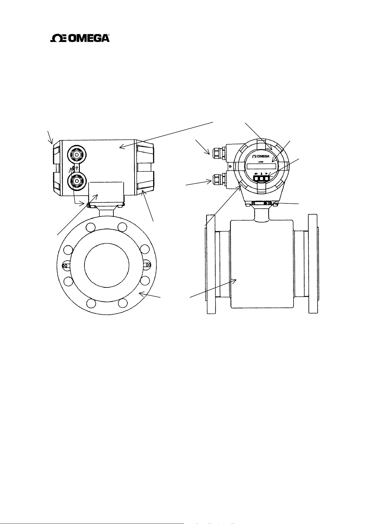
3. Names of Parts
N
play
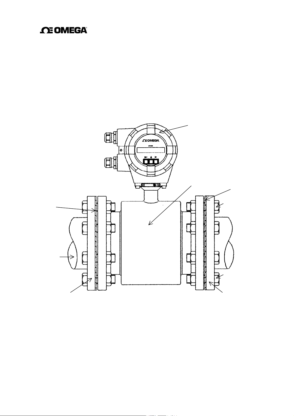
The outline drawing of the FMG400 Series flange type flowmeter is shown in Figure 3.1 and
the internal views of the converter are shown in Figures 3.2 and 3.3.
Outline Drawing
Housing cover
for terminal board
Grounding terminal
ameplate
Port for power cable
Port for I/O
cable
Housing cover for
LCD dis
Detector
Converter
LCD display
Control keys
Flow derection arrow
Figure 3.1 Outline drawing of FMG400 Series flange type Flowmeter
11
Page 13
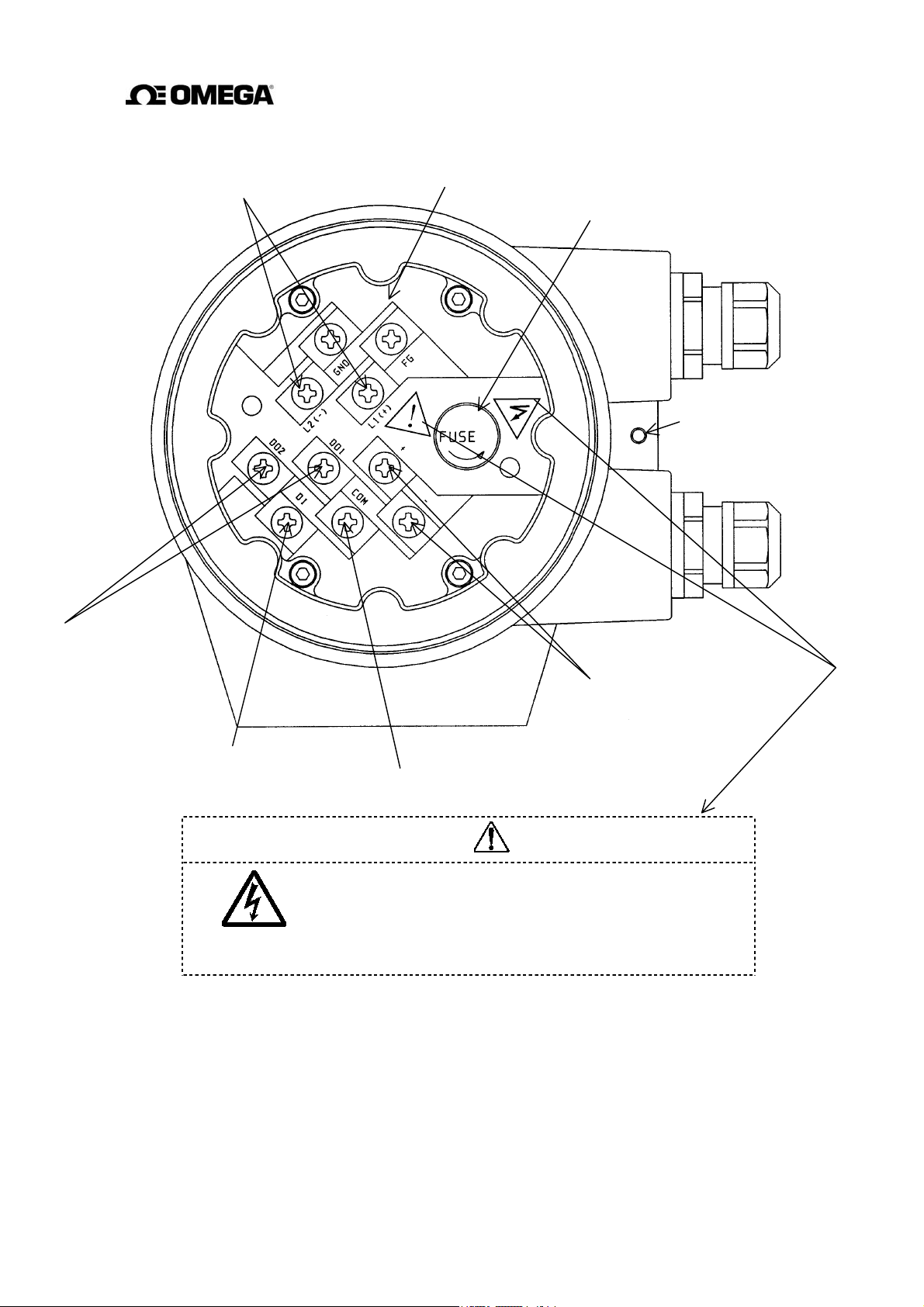
Terminal Board of Converter
Power supply teminals
Internal ground terminal
Fuse
External grounding
terminal
Digital output terminals
Digital input terminal
宜しくお願い致します。
Figure 3.2 Terminal Board of Converter
Current output terminals
Signal COMMON for DI, DO1, DO2
CAUTION
The seal shown in the left figure is attached to near the
power supply wiring terminals. Be careful not to get
electric shock.
12
Page 14
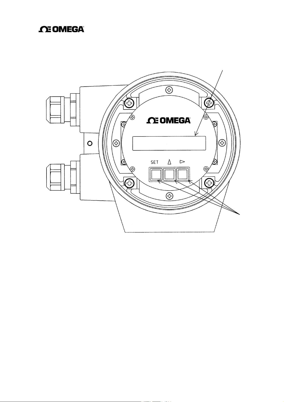
Control switch or keys of Converter
LCD display
Figure 3.3 Control switch or keys of Converter
Control keys
13
Page 15
4. Installation
Safety Precautions for Installation
WARNING
Do not use the FMG400 Series in an
Using this product in an explosive atmosphere can
cause explosion.
explosive atmosphere
DON’T
CAUTION
Install a switch and fuse to isolate the
FMG400 Series from main power.
Power supply from main
power can cause electric
shock or circuit breakdown.
DO
Do not modify or disassemble the
FMG400 Series unnecessarily.
Modifying or disassembling
this product can cause
DON’T
Do not work on piping and wiring with
wet hands.
electric shock,
or damage to this product.
Wet hands may result in
electric shock
malfunction
DON’T
.
Use an appropriate device to carry and
install the FMG400 Series.
If his product falls to the
ground, injury, or malfunction
DO
Ground the FMG400 Series
independently from power equipment.
of or damage to the product,
can be caused.
Operating this product without
grounding can cause electric
shock or malfunction.
DO
The label shown left is placed
near the terminal board for
power input.
(A
black border and symbol on
yellow triangle)
Be alert to electric shock.
4.1 Location
To select the installation site, follow the precautions described below:
Avoid places where fluid runs in a pulsating form.
Avoid places within the immediate proximity of equipment producing electrical
interference (such as motors, transformers, radio transmitters, electrolytic cells, or other
equipment causing electromagnetic or electrostatic interference).
14
Page 16
Avoid places where excessive pipe vibration occurs.
Avoid places where there is direct sunlight. If this is unavoidable, use an appropriate shade
Avoid places where corrosive atmospheres or high humidity conditions obtain.
Avoid places of too great an elevation or constricted areas where clearance for installation
or maintenance work is not provided.
Design piping so that the detector pipe is always filled with fluid, whether the fluid is
flowing or not.
The detector has no adjustable piping mechanism. Install an adjustable short pipe where
needed.
Chemical injections should be conducted on the downstream side of the flowmeter.
* For cautions on piping work such as the installation positions of piping and lengths of
straight pipes, see Section 4.3.
4.2 Mounting
CAUTION
Use an appropriate device to carry
and install the FMG400 Series.
If his product falls to the
ground, injury, of
DO
malfunction of or damage
to the product, can be
caused.
Turn off main power before
working on pipes.
Working on pipes while
power is applied can
DON’T
cause electric shock.
IMPORTANT
When high-temperature fluid is being measured, radiant heat from the detector pipe surface
and adjoining pipes may cause the ambient temperature of the converter to go above 60 °C.
If the ambient temperature goes above 60° C, try to lower the temperature by measures such
as wrapping heat-insulating materials over the detector pipe and adjoining pipes.
4.2.1 Piping Inspection
Before installing the pipes, make sure that there is no inclination of pipes or tube axial
displacement (eccentricity) as shown in Figure 4.1. Forced installation of the flowmeter in
inclined pipes may cause destruction of the detector or leakage of the fluid. Installing the
flowmeter in pipes with the presence of eccentricity may cause local friction of the lining or
earth ring and measurement errors depending on the properties of the fluid.
Before installing the pipes, flush the pipe interior to remove foreign matters in the pipes.
15
Page 17

Eccentricit
y
Inclination
(a) Inclination of pipe (b) Tube axial displacement
(eccentricity)
Figure 4.1 Bad Examples with Inclination of Pipe and Tube Axial Displacement
(Eccentricity)
4.2.2 Cautions on Carrying Equipment
In order to prevent damages to the equipment, carry it packed as was at the time of delivery to
the installation location and unpack it there.
As the detector whose nominal diameter is 200 mm comes with eyebolts, lift the equipment as
shown in Figure 4.2 (a).
As the detector whose nominal diameter does not exceed 150 mm comes with no lifting means,
lift the equipment as shown in Figure 4.2 (b). The weights of the detectors with different
nominal diameters are described in Chapter 15 "Outline Dimensions."
Lifting the detector of any nominal diameter by pressing a bar into the detector pipe may
damage the lining, preventing stable measurement. Never do this under any circumstances.
* Lifting should be performed under instructions of qualified personnel of crane or slinging
work.
16
Page 18
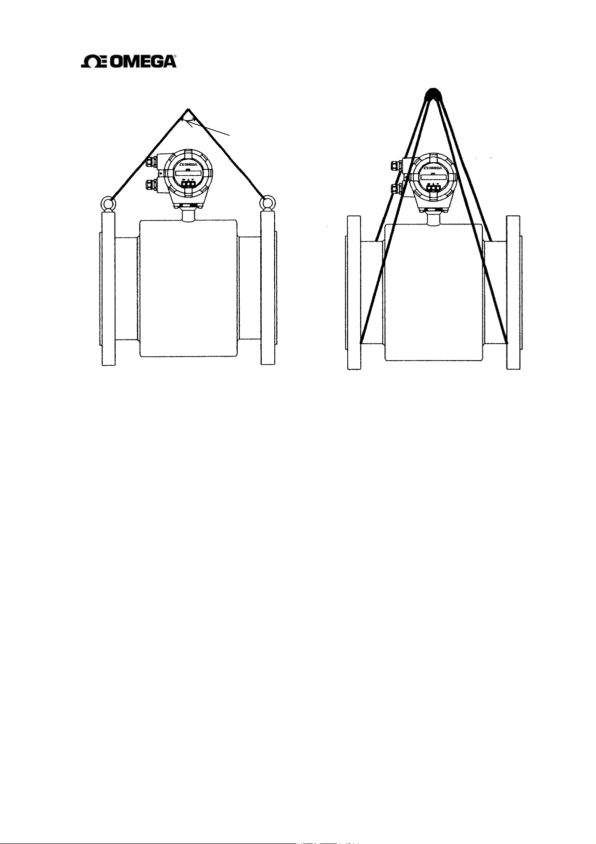
90° or less
(a) With nominal diameter of 200 mm (b) With nominal diameter of 150 mm or
less
Figure 4.2 Lifting Method
4.2.3 Mounting Procedure
To mount the FMG400 Series flange type, place it between the upstream and downstream pipe
flanges and tighten it with flange bolts and nuts. See Figure 4.3 and follow the procedure
below:
1. Insert two lower mounting bolts through the clearance holes in the upstream (or
downstream) pipe flange.
2. Install a packing next to the upstream (or downstream) flange face and the other packing
next to the downstream (or upstream) pipe flange. The two mounting bolts can now be
guided through the clearance holes in the downstream packing and flange.
3. Place the FMG400 Series flowmeter between the two flange packings, with the flowmeter
detector body above the two bolts. The flowmeter must be oriented in accordance with the
flow direction arrow.
4. Install the two upper mounting bolts through the clearance holes in the upstream and
downstream packings and flanges. Then install the remaining mounting bolts depending
on the flange pattern used.
5. Thread nuts on both ends of the 4 (or more) mounting bolts, finger tight.
17
Page 19
6. While centering the flowmeter with the longitudinal axis of the pipeline, tighten the nuts
g
with a wrench diagonally across in even increments.
Note that the flowmeter detector pipe axis must be aligned with the pipeline axis on both
upstream and downstream sides. This is essential to have stable characteristics of flow
measurement (especially for flowmeters with meter sizes of 50 mm or less).
* In the case of a detector using teflon PFA lining, bolts may get loose with time because of
plastic deformation of teflon. Tighten them periodically.
Converter
Packing
Flow direction
Upstream flange
Detector
Figure 4.3 FMG400 Series flange type flowmeter-piping connections
Packin
Upper mounting bolts
Lower mounting bolts
Downstream flange
18
Page 20
4.3 Piping Connections
(1)
(2)
(3)
)
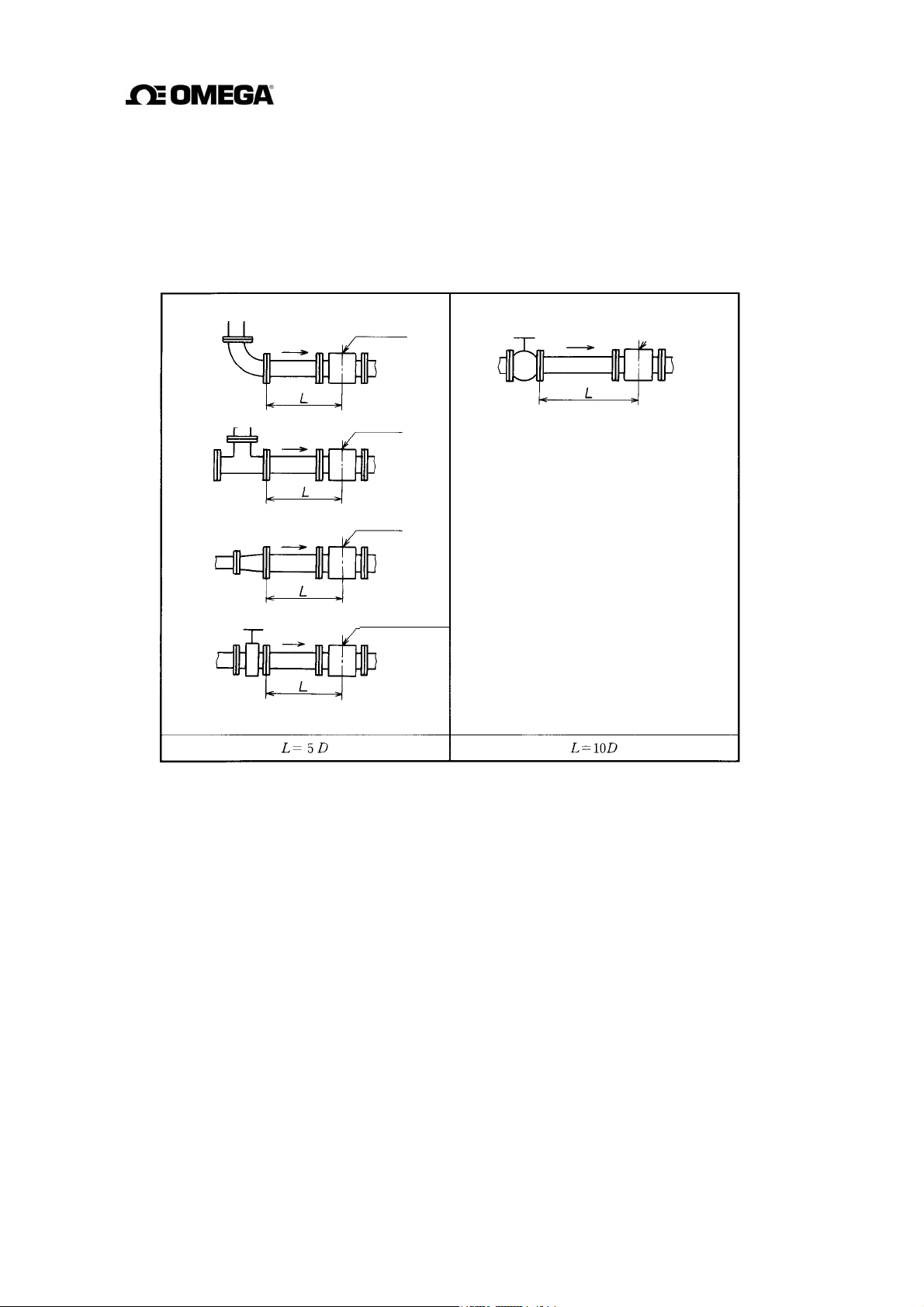
(1) Required Pipe Length
If various joints are used upstream of the detector outlet, the straight pipe length as shown in
Table 4.2 is required.
Table 4.2 Required straight pipe length on the upstream side
90° bent
Tee
Diffuser
(4)Fully opened sluice valve
Detector
Detector
Detector
5. Other valves (not fully opened
Detector
L: Required straight pipe length—straight pipe length plus half-length of the detector.
D: Nominal bore size (diameter)
NOTES
1. The length of a reducer, if connected, can be counted as a part of the straight pipe length.
2. No straight pipe length is needed on the downstream side. If a butterfly valve is installed
downstream of the detector, do not let the valve plate protrude into the pipe of the detector.
19
Page 21
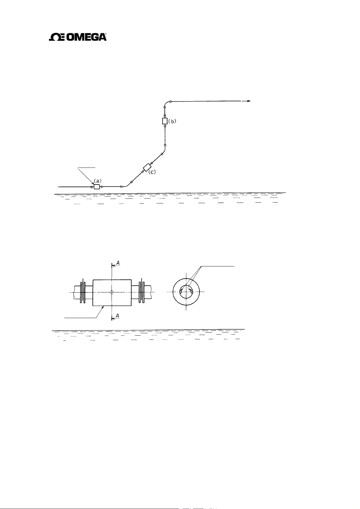
(2) Pipe Orientation
The detector may be installed in horizontal, vertical or sloping pipe runs as shown in Figure 4.4.
However, except for horizontal installation, fluid should flow from lower to upper directions.
See Figure 4.4.
Flow direction
(a) Horizontal pipe installation
(b) Vertical pipe installation
(c) Sloping pipe installation
Detector
Ground surface
Figure 4.4 Detector Piping Orientation
The electrodes should be positioned horizontally against the ground surface in any piping
installation. See Figure 4.5.
Detector
-
-
Figure 4.5 Installation position of the detector
20
Page 22
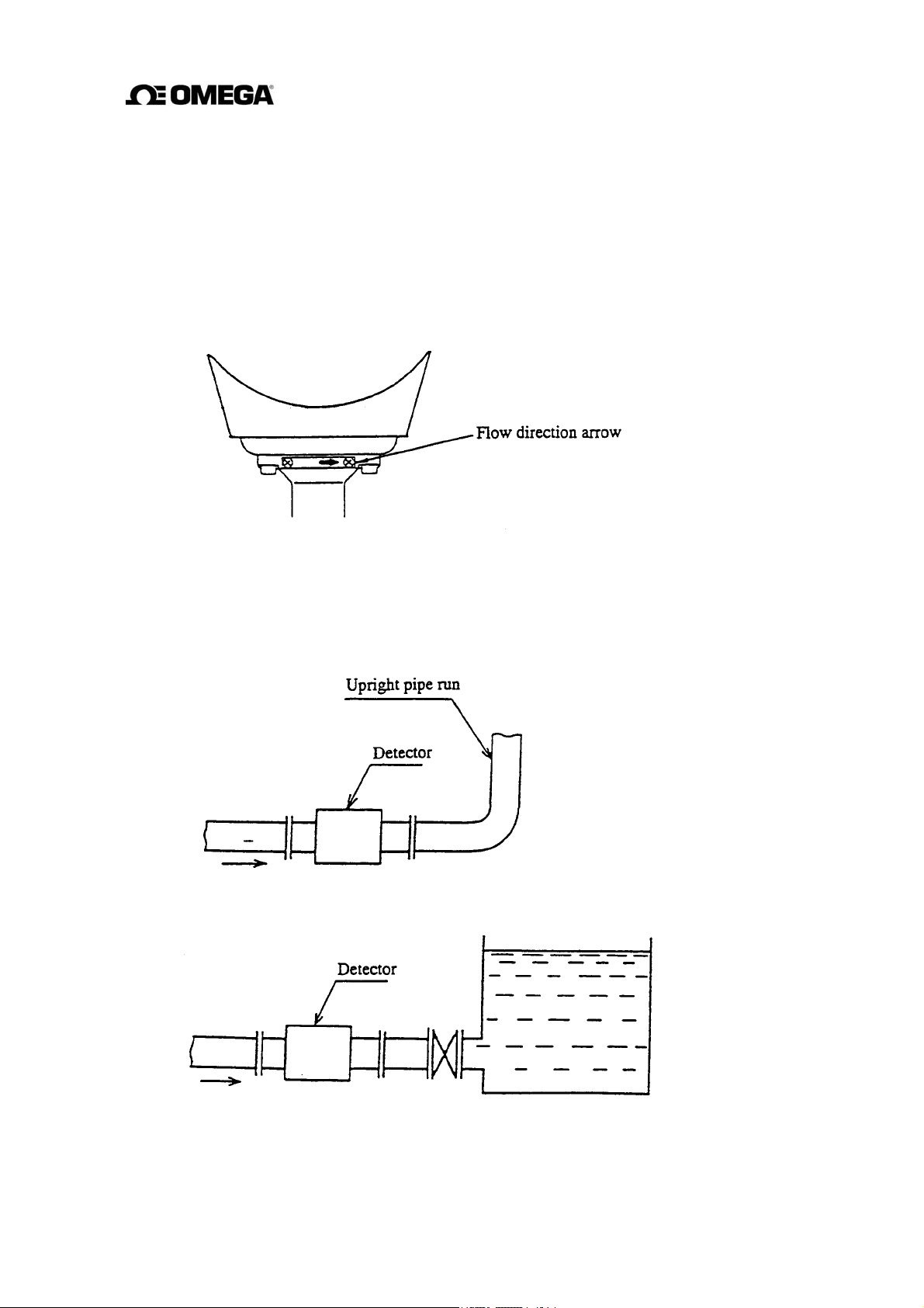
(3) Flow Direction
Install
the detector in accordance with the flow direction arrow on the detector. See Figure 4.6. If
the
actual flow runs opposite to the specified flow direction, the following display and output
appears. (For bi-directional multi-range measurement, see 10.3, “Multi-range Functions.”).
• LCD display : Instantaneous flow rate—indicates negative values,
Totalized flow—no counts added.
• Output: Current output— 4.0 mA output; Pulse output—No pulses
Figure 4.6 Flow direction arrow on the detector
(4) Preventing an Empty Pipe Condition
Design an upright pipe run (Figure 4.7) or sufficient head pressure (Fig. 4.8) at the downstream
detector outlet if there is a possibility of the detector pipe becoming emptied.
Figure 4.7 Detector with an upright pipe run at downstream outlet
Figure 4.8 Detector with sufficient head pressure at downstream outlet
21
Page 23
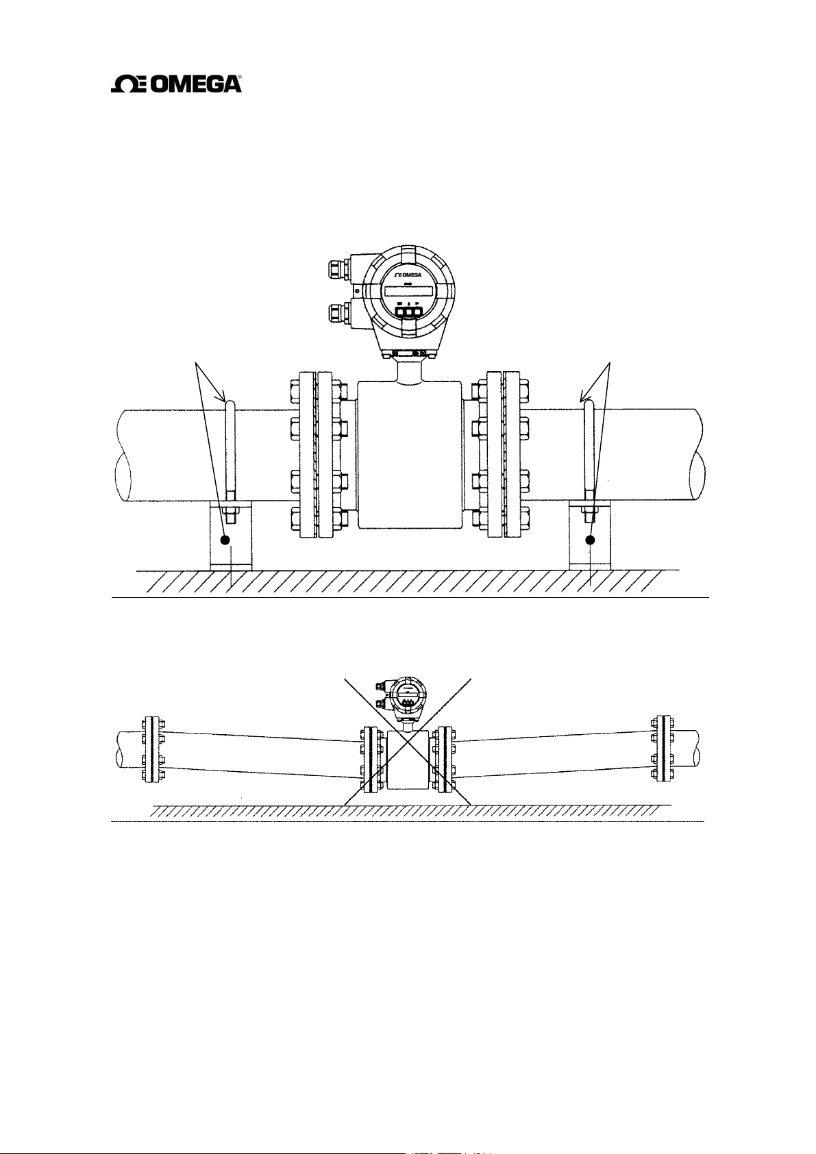
(5) The pipes on both sides of the installation location of the detector should be fixed by attaching
support fittings, etc. Supporting the pipes will not only reduce piping vibration but also
prevent damages to the piping due to dead weight of the electromagnetic flowmeter and
weight of the fluid. (See Figure 4.9 and Figure 4.10.)
Piping support fitting Piping support fitting
Figure 4.9 Example of Pipe Fixing Method
Figure 4.10 Unsupported Piping Model
22
Page 24
5. Wiring
CAUTION
Do not work on piping and wiring with
wet hands.
Wet hands can cause
system failure.
DON’T
Do not modify or disassemble the
FMG400 Series unnecessarily.
Modifying or
disassembling this product
DON’T
Flowmeter accuracy may be affected by the way wiring is executed. Proceed with wiring
taking the following precautions:
(1) Select the cable runs away from electrical equipment (motors, transformers, or radio
transmitters) which causes electromagnetic or electrostatic interference.
(2) Deterioration of flowmeter circuit insulation occurs if the converter interior or cable
ends get wet or humidified. This in turn causes malfunction of the flowmeter or noise
problems. Avoid a rainy day if the flowmeter is to be installed outdoors. Even indoors,
prevent water from splashing over the flowmeter. Try to finish the wiring as quickly as
possible.
can cause electric shock,
malfunction of or damage
to this product.
Ground the FMG400 Series properly.
Operating this product
without a grounding can
DO
cause system malfunction
The label shown left is placed
near the terminal board for
power input.
Be alert to electric shock.
(3) The converter has a surge-absorbing barrier installed inside. Therefore, do not conduct
a withstand voltage test for the converter. To check the insulation of the converter, use
a voltage of 250 V
dc or less.
23
Page 25
5.1 Cables
Use the kind of cables shown in Table 5.1 to wire the converter.
Table 5.1 Cables
Name Cable type
Power cable
Three-wire sheathed
Nominal crosssectional area
2 mm² 11 to 13 mm
Overall
diameter
cable (Note)
I/O cable
The number of wires for the output cable depends on the
system specifications. Use a shielded cable with nominal
cross-sectional area of 1.25 mm² and overall diameter of
11 to 13 mm.
Note: Use a four-wire cable if the arresters are to be used. See Figure 5.1 below.
5.2 External Device Connections and Grounding
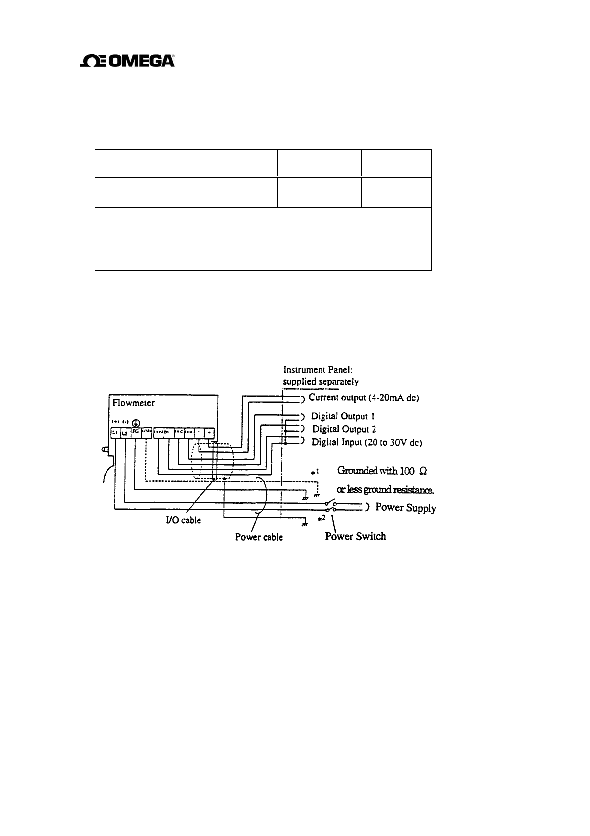
The terminal board connections of the FMG400 Series flowmeter are shown in Figure 5.1.
Proceed with wiring as described in Section 5.4, “Wiring Procedure.”
If power supply is specified as DC, use L1 as positive (+) and L2 as negative (–) terminals.
1
To use the arresters, ground the GND terminal using a wire shown in broken line.
*
2
Locate an external double-pole power switch on the power line near the flowmeter and within
*
easy operation.
Mark on the switch as the disconnecting device for the flowmeter.
Use the proper switch as follows.
Recommended switch rating; Rating AC250V 6A or more
Inrush current 15A or more
Figure 5.1 Terminal Board Connections
24
Page 26
IMPORTANT
(1) The grounding terminal of the FMG400 Series flowmeter should be grounded with
100 ohm or less ground resistance. Use a heavy copper braid or wire (cross-sectional
area 5.5 mm
terminal is M4 size and an M4-size crimped ring lug should be used to connect the
wire to the terminal. Avoid a common ground where earth current may flow.
independent
and non-conductive pipeline grounding procedures.
(2) To prevent a two-point grounding, ground the shielded cable on the receiving
instrument side.
2
minimum) to ground the terminal and make it as short as possible. The
An
ground is preferable. See Figure 5.2. for a conductive pipeline grounding
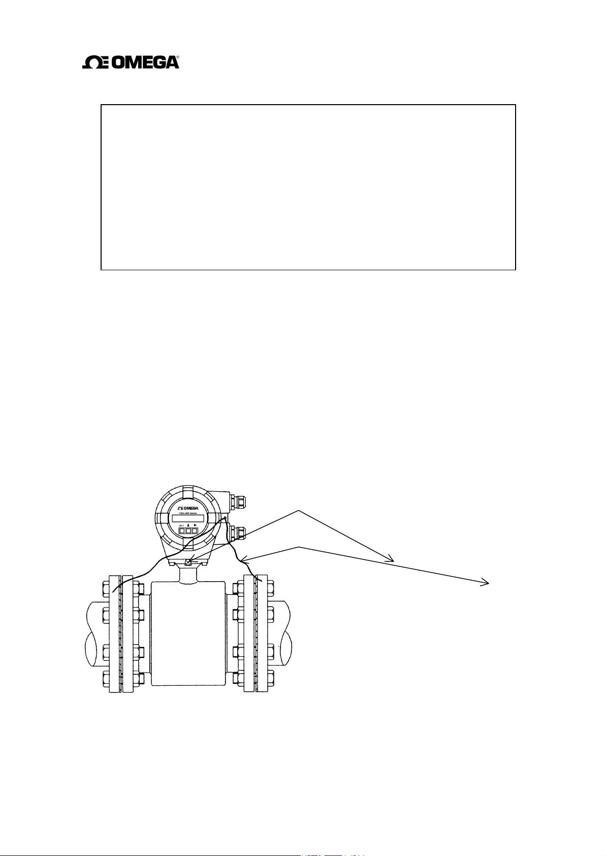
If connection pipe is conductive:
(1) Connect between the grounding
terminal
and both ends of the mating
flanges with a heavy copper braid or
wire (cross sectional area 5.5 mm
minimum).
(2) If the conductive pipe is not
grounded
to a
good earth ground, use
the same type of copper braid or
wire
to
ground the terminal with 100
ohm or less ground resistance.
Grounding terminal
Grounding wire
If connection pipe is non-conductive:
(1) Use a heavy copper braid or wire
(cross sectional area 5.5 mm²
minimum) to ground he terminal with
2
100 ohm or less ground resistance.
25
Page 27
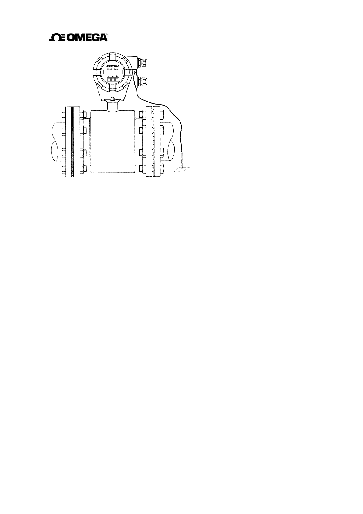
Figure 5.2 Grounding Procedure
26
Page 28
5.3 Digital I/O Connections
(
)
r
Digital I/O terminals consist of contact output terminals, voltage signal input terminal (DI), and
signal common terminal (COM). Each terminal (DO1, DO2 and DI) is isolated from internal
circuits. Terminal (COM) is the signal common for the other three terminals (DO1, DO2 and
DI).
Functions can be assigned for each terminal with the LCD control keys. See Chapter 10,
“Digital I/O Functions.”
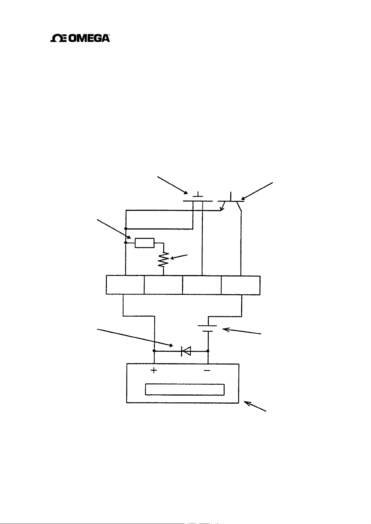
To connect an electromagnetic relay or counter to the contact output terminal (DO1 or DO2),
put a surge-absorbing diode into the input circuit of the relay or counter. See Figure 5.3 for an
example of electromagnetic counter connection.
Solid-state relay Transistor open collector
Resisto
COM DI DO2 DO1
Diode
Note
* Note. Be sure to use a surge absorption diode with a rated current of 1 A and rated withstand
voltage of 200 V Min.
Figure 5.3 Electromagnetic Counter Connection Example
Power supply
27
Page 29
5.4 Wiring Procedure
Cable termination and cable connections are described below.
5.4.1 Cable Termination
CAUTION
Do not conduct wiring work when
power is applied.
Wiring while power is
applied can cause electric
DON’T
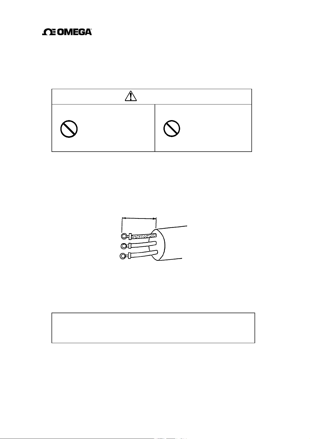
Use cables as specified in Table 5.1. Remove about 30 mm of the end of cable sheath to expose
the two coated wires and then strip the wires about 10 mm. Then attach an M4-size crimped
ring-lug to the end of each wire using a compression tool. The crimped ring-lug should be of
the kinds with insulated sleeve to prevent shorts between adjacent terminals. The overall length
of the wire with the M4-size ring-lug attached should be about 35 mm. See Figure 5.4.
shock.
35 mm
Do not work on piping and wiring
with wet hands.
Wet hands may result in
electric shock.
DON’T
Figure 5.4 Termination of cables
5.4.2 Cable Connections
Connect the terminated cable wires to the terminal board as described below.
IMPORTANT
Connect the wires securely to the terminal board. A loose connection may result in
unsatisfactory flowmeter performance. Make sure the wires are securely connected.
28
Page 30
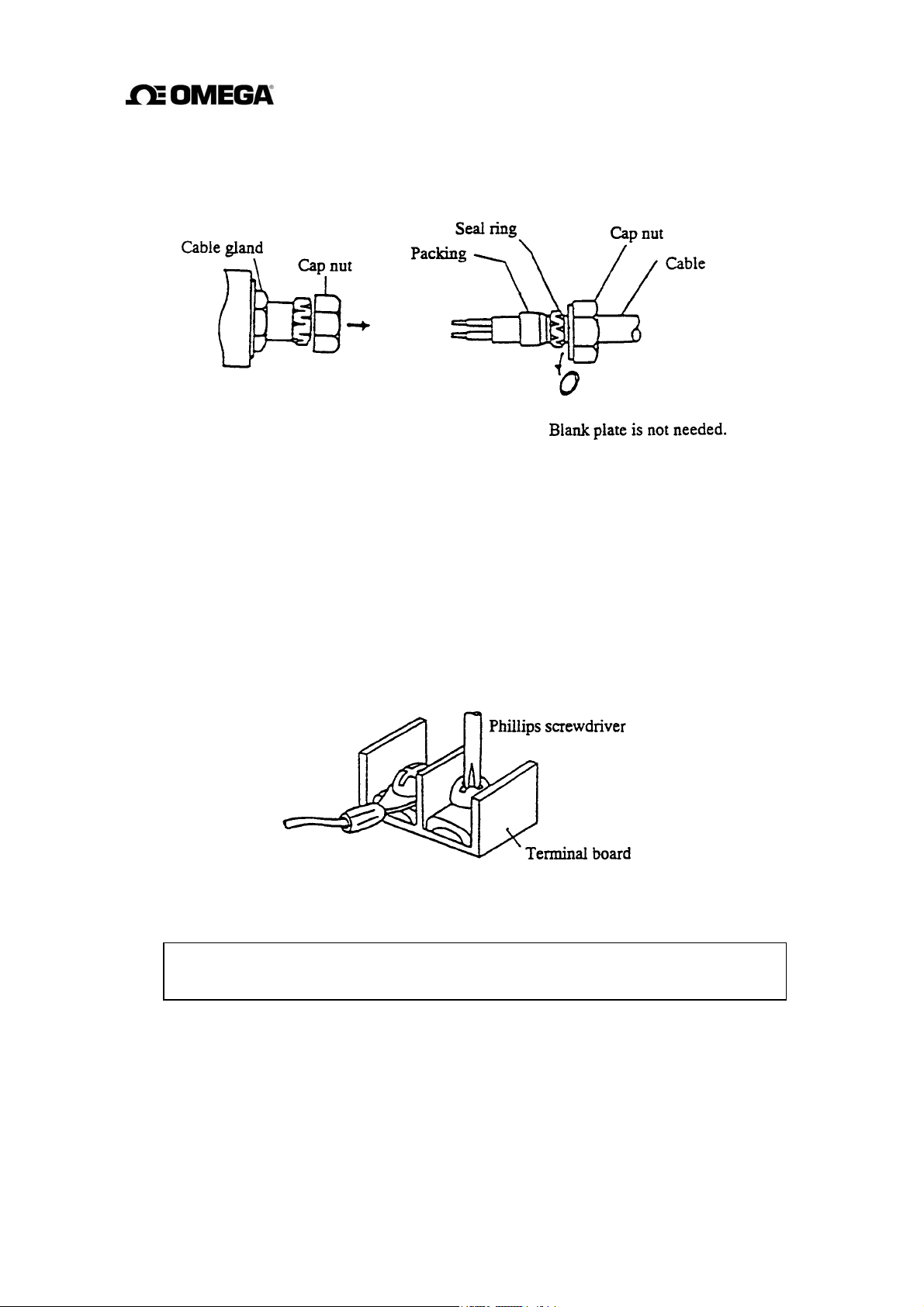
(1) Remove the cap nut from the cable gland and put the terminated cable through the cap nut,
seal ring, and packing as shown in Figure 5.5 on the right. The blank plate inside the cable
gland used when shipped is not needed once the cable is wired.
Figure 5.5 Cable connections
(2) Remove the housing cover for the terminal board shown in Figure 3.1. The terminal board is
located inside the converter as shown in Figure 3.2. Connect the crimped terminal of each
wire to the specified pin of the terminal board. See Figure 5.1 for the terminal board
configuration. Tighten each crimped terminal to the terminal board with a screw using a
Phillips screwdriver as shown in Figure 5.6. Loose connection may result in unsatisfactory
flowmeter performance. Make sure the wire is securely connected.
Figure 5.6 Terminal board connections
NOTE
The appropriate torque for tightening the terminal board screws is 1.2 Nm (12 kgf·cm).
29
Page 31

(3) After the terminal board connection, pull the cable a little so that the cable runs straight from
the terminal board without unnecessary winding.
However, if the sheath-removed part goes as far as where the packing is located, air may
leave through there and the airtight structure may not function. See the incorrect example in
Figure 5.7. Then tighten the cap nut with a wrench.
Figure 5.7 Cabling Procedure
(4) Attach the terminal cover and screw the housing cover for the terminal board. To keep the
housing seal, tighten the cover securely, using a tool fitting with the groove on the cover.
30
Page 32

6. Operation
CAUTION
Do not touch the FMG400 Series main
body when high temperature fluid is
being measured.
The fluid raises the main
body temperature and can
DON’T
6.1 Preparatory check
Follow the procedure described below to prepare before starting the flow measurement.
System Check
Check the wiring between the converter and related instruments.
Make sure all the bolts of connection flanges on which the flowmeter is
mounted securely tightened.
Make sure the direction of flow arrow is in accordance with actual flow.
Make sure the flowmeter is grounded with 100 ohm or less ground resistance.
cause burns when touched.
Make sure the converter housing covers are securely tightened.
Placing System On-Stream
Let the fluid go through the detector pipe. When the detector is filled with the
fluid, stop the fluid and keep it still in the detector pipe.
Supplying Electric Power
Make sure the power supply is as specified.
Checking Converter Parameters
Check the configuration parameter settings. Refer to Chapter 7, “LCD
Display and Controls,” along with Chapter 8, “Configuration Parameter
Setting”.
Zero Adjustment
Wait for 30 minutes to warm up the flowmeter. Then making sure the fluid
holds still in the detector pipe, starts the zero adjustment. Refer to 6.2, “Zero
Adjustment.”
On-line measurement
After checking the items and conducting the zero adjustment as listed above,
let the fluid go through the detector pipe. Output (4–20 mA dc) directly
proportional to the flow rate can be obtained.
31
Page 33

6.2 Zero Adjustment
To conduct zero adjustment of the flowmeter, the fluid in the detector pipe must be held still.
To start the zero adjustment is pressing a combination of control keys for the model with LCD
display (see 8.2.8, “Zero Adjustment”).
Press the zero adjustment switch for more than 3 seconds.
(Note that once the zero adjustment is started, there is no way to cancel the zero adjustment
sequence.)
An LED lamp is ON during zero point adjustment.
Then the LED indicator lights and the zero adjustment sequence will start. The zero
adjustment sequence lasts about 3 to 6 seconds. (Zero adjustment duration depends on the
excitation current frequency. It takes about 3 seconds for 24 Hz setting and about 6
seconds for 12 Hz and 6 Hz settings.)
When the zero adjustment sequence ends, the LED indicator goes off.
To conduct the zero adjustment, it is necessary to open the converter housing cover and press
the switch. Observe the following precautions when you open the housing cover:
(1) Do not open the cover in the open air unprotected against rain or wind.
If you adjust the flowmeter in the rain, this can cause electric shock or damage to the
flowmeter electronics. If wind blows against the internal circuitry of the converter, output
may fluctuate and fail to indicate correct measuring values.
(2) Do not conduct the zero adjustment when the ambient humidity is high. By opening the
cover in high humidity conditions, the measuring accuracy may be reduced or damage
caused to the flowmeter electronics.
32
Page 34

7. LCD Display and Controls
You can select the operation mode, change the configuration parameters or execute
operation-specific functions using the control keys on the panel. How to operate these
keys is described in this chapter.
7.1 Outline
The Converter has a LCD display. The LCD display can be used to set and indicate various
configuration parameters. Figure 7.1 shows the front view of LCD display.
FMG400 Series
LCD display
Figure 7.1 Converter with LCD display
LCD display (2-line × 16-character)
The backlit display enables an easy-to-read indication even under poor lighting conditions.
Instantaneous flow rates or totalized flow in the measurement mode, or configuration
parameters in the setting mode can be displayed.
33
Control keys
Page 35

Control Keys
Changing the operation mode, checking or changing parameters can be done with these keys.
To operate these keys, you have to open the converter housing cover. Observe the following
precautions when you open the housing cover:
(1) Do not open the housing cover in the open air unprotected against rain or wind.
If you open the housing cover in the rain, it can cause electric shock or damage to the
flowmeter electronics. If wind blows against the internal circuitry of the converter, output
may fluctuate and fails to indicate correct measuring values.
(2) Do not open the housing cover when the ambient humidity is high. By opening the cover
in high humidity conditions, the measuring accuracy may be reduced or damage caused to
the flowmeter electronics.
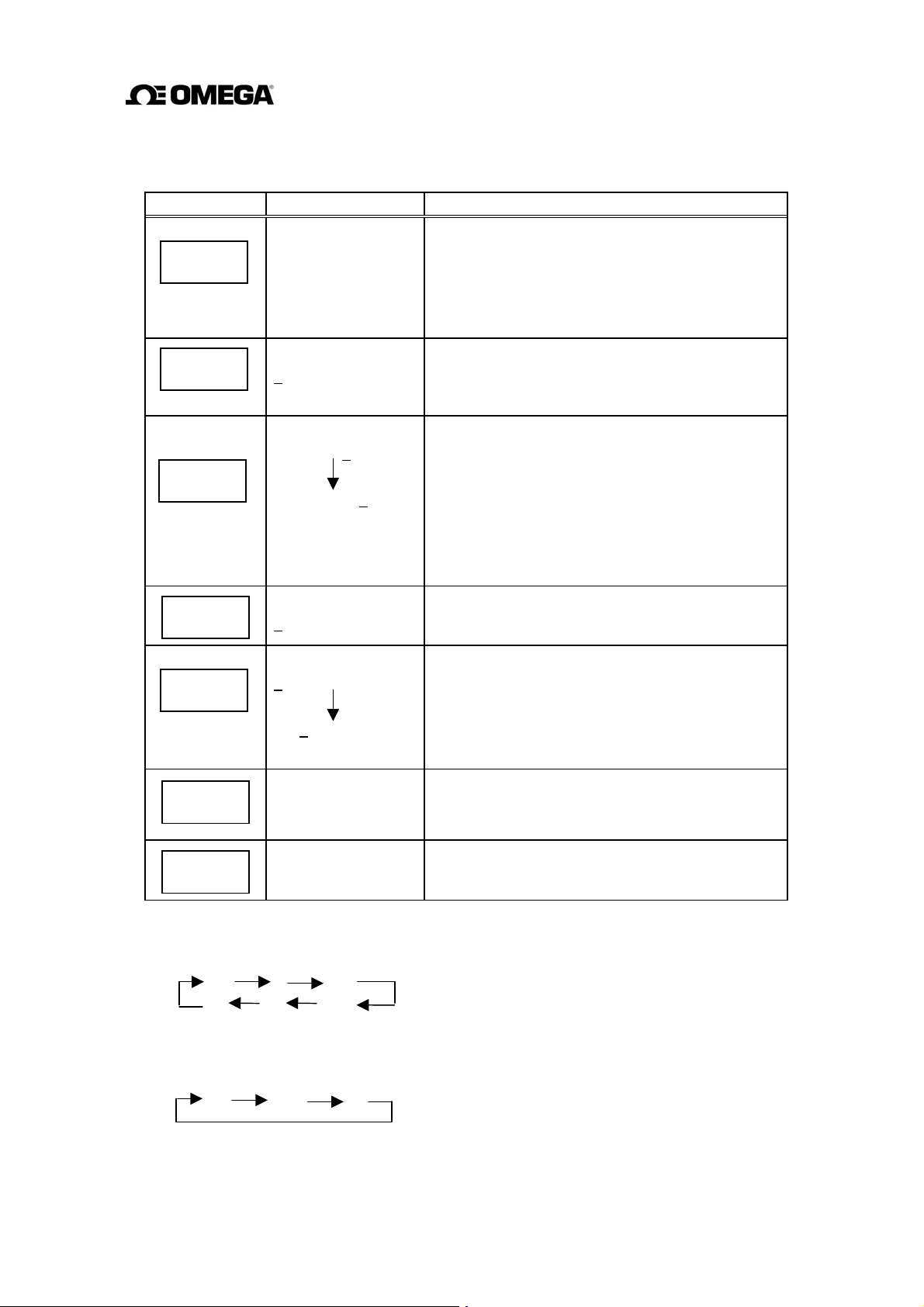
Functions of each control key when pressed are shown in the table below.
Control keys Basic functions of control keys
Goes into the item selection sequence.
SET
5
4
Goes into the detailed-item specifying sequence for each selected item in
measurement, setting or calibration modes.
Stores the selected data in the setting mode.
Changes items (alphabet letter and number) in the items selection
sequence, and changes parameters (numbers and/or units) in the detaileditem specifying sequence in measurement, setting or calibration modes.
Starts and stops the totalizer in the measurement mode. (Note)
Changes digits (alphabet letter and number) in the items selection
sequence, and starts the detailed-item specifying sequence by indicating
the left-most digit with the cursor.
Moves the cursor from left to right (from the right end reverts to the left
end) in the above sequence.
Resets the totalizer in the measurement mode. (Note)
Note: To operate the totalizer, it is preferable to set the indicating unit (UNIT 1 and/or UNIT 2)
to one of the units appropriate for totalization just to make sure it is operating correctly. See 10.2,
“Totalizer and Pulse Output.”
34
Page 36

7.2 Display Format
In the measurement mode, measured data are displayed in UNIT 1 (primary indicating unit)
and UNIT 2 (secondary indicating unit). As to indicating units, see 8.2.4, “Indicating Unit.”
Display Format
Measured Value Display Forma
(1) Flow rate
t
35
Page 37

(2) Totalizer
(3) Volumetric flow
“C” is indicated when totalized flow is counted.
Increments per counting rate. Refer to 8.2.10,
“Counting Rate.”
Wraps around after 99999999.
“F” for forward and “R” for reverse direction flow
will be displayed
Displays down to the smallest digit of
“C” is indicated when volumetric flow is counted.
The unit of flow
8 digits (99999999) maximum including decimal point
(4) % display
If the flow count exceeds 99999999, wraps around.
“F” for forward and “R” for reverse direction flow
will not displayed.
Displayed down to 0.1 %.
Displays up to 125.0 %.
Flow direction: Forward “
“ (blank space);
Reverse “-“
36
Page 38

7.3 Basic operations
Flow measurement in the measurement mode, checking or changing configuration
parameters in the setting mode and a converter unit check in the calibration mode are
the basic operations of the converter.
7.3.1 Mode Change
The converter has three operation modes: measurement, setting and calibration. The system
stays in the measurement mode after the power is turned on. To change the mode to the setting
or calibration mode, press [SET] and select the desired item using
return to the measurement mode, select “0” (MEASURE MODE) for the number column of
configuration items (such as A0 or B0) . See 7.4, “Configuration Items Selection Table.”
Measurement mode:
process values. The flowmeter can measure the flow velocity, flow rates, or totalized flow.
The flowmeter first goes into this mode when power is turned on.
Setting mode:
measurement mode. These parameter values are displayed while checking or changing these
values but the flowmeter outputs the measured process values as in the measurement mode.
See 7.4, “Configuration Items Selection Table” and 8.2, “Checking or Changing
Parameters” for details. Configuration items are from A1, A2, A3 to M1.
Calibration mode:
simulation signal is used to check the measuring span and excitation current value. The
current output of the flowmeter changes in accordance with the simulation signal. The
status of each digital output is held to the value just before the system moved into the
calibration mode. See 7.4, “Configuration Items Selection Table” and Chapter 9,
“Calibration” for details. Configuration items are from N1 to N4.
used to check or change various configuration parameters used in the
measures the process flow and displays and outputs the measured
used to check the converter internal circuits. The internally generated
[4]
and
[5]
keys. To
37
Page 39

7.3.2 Configuration Parameter Selection in Setting and Calibration Modes
Follow the procedure described below to select configuration items in the setting and
calibration modes. The key on the left should be pressed to start each sequence described on
the right.
Measurement mode
Goes into the item selection sequence. In this sequence, each
SET
4
item is indicated by a combination of an alphabet letter and a
number.
Selects the desired item (indicated by an alphabet letter and a
number) first by selecting the digit (alphabet or number) with
[4]
and then changing the value with
[5]
5
SET
4
4
5
SET
SET
SET
Displays the parameter for the selected item.
Goes into the parameter changing sequence. The digit
indicated by the cursor can be changed.
Changes
the cursor) using
with
Flickers the selected value and/or unit to confirm changes
made for the selected item.
Stores the indicated value and/or unit and stops flickering of
the data.
Returns to the items selection sequence.
the value and/or unit first by selecting the digit (with
[4]
and then changing the value or unit
[5].
(Note 2)
(Note 1)
Notes
1. To return to the measurement mode, select “0” (MEASURE MODE) for the number
column of any items (such as A0 or B0).
2. To return to the parameter changing sequence, press
38
[5].
Page 40

7.4 Configuration Items Selection Table
In the setting and calibration modes, configuration items can be selected as shown below. For
example, the excitation current can be selected by the item A1. To change the parameters for
the selected items, see the following chapters. To return to the measurement mode, select “0”
for the number (such as A0 or B0).
Setting mode items (A1, A2, A3 to M1): See Chapter 8, “Configuration Parameter Setting.”
Calibration mode item (N1 to N4): See Chapter 9, “Calibration.”
0123456
Excitation
*
A
Current
Indicating
*
B
Unit 1
Range Type Range 1 Range 2 Range 3 Range 4 Range
*
C
Damping
*
D
Constant
Zero
*
E
Adjustment
DO1
*
F
Function
Counting
*
G
Rate
Preset Count
*
H
High Alarm
*
I
Set
Meter Size Excitation
Frequency
Indicating
Unit 2
Low Cutoff
DO2
Function
Pulse Width
High Alarm
Value
DI Function
Low Alarm
Set
Hysteresis
Low Alarm
Value
Empty Pipe
*
J
Alarm
Rate-of-
*
K
change Limit
Fixed-value
*
L
Output
Zero Offset
*
M
Adjustment
Flow Rate
*
N
Cal 0%
* Returns to the measurement mode.
Control Limit
Time
Fixed-current
Output
Flow Rate
Cal 50%
Fixed-pulse
Output
Flow Rate
Cal 100%
39
Page 41

8. Configuration Parameter Setting
8.1 Configuration Items
To check or change parameters, first select the desired configuration item as described in 7.3.2.
The configuration items are listed below. See each section for detailed procedure.
The default set value in each configuration item is shown in Appendix 2.
Section Configuration item Display example Page
8.2.1
8.2.2
8.2.3
8.2.4
8.2.5
8.2.6
8.2.7
8.2.8
8.2.9
8.2.10
8.2.11
8.2.12
Excitation Current
Meter Size
Excitation Frequency
Indicating unit
Range Type
Span (range)
Hysteresis
Damping Constant
Low Cutoff
Zero Adjustment
Digital I/O
Counting Rate
Pulse Width
Preset Count
High/Low Alarm
Alarm Limit Value
A1: EX. CURR. 0.2100 A
A2: METER SIZE 50 mm
A3: EX. FREQ. 24 Hz
B1: UNIT 1 m/s
C1: RANGE TYPE
C2: RANGE 1
C3: RANGE HYST
D1: DAMPING 05.0 SEC
D2: LOW CUT 05.0 %
E1: ZERO ADJUST 00.1 %
F1: DO1 FUNC. 1: H ALM
G1: COUNT RATE
G2: PLS. EIDTH
H1: PRESET 009000
I1: H. ALARM SET
I2: H. ALARM VAL
1:SINGLE
01.000 m/s
05.0 %
6.00E-1l
020 m/s
ON
+100.0 %
40
41
42
44
46
51
52
53
54
56
58
59
8.2.13
8.2.14
8.2.15
8.2.16
Empty Pipe Alarm
Rate-of-change Limit
Control Limit Time
Fixed-value Output
Zero Offset Adjustment
J1: EMPTY ALM ON
K1: LIMIT RATE
K2: LIMIT TIME
L1: FIXED OUT OFF
M1: MANUAL ZERO -000.1 %
40
05.5 %
01 SEC
62
63
65
68
Page 42

8.2 Checking or Changing Parameters
8.2.1 Excitation Current
Proceed as follows to check or change the excitation current setting value.
To check the exciting current setting value:
Key operation Display example Description
A1: EX. CURR.
0.2100A
SET
SET
To change the excitation current setting value:
A1: EX. CURR.
Press [SET] first to start the item selection sequence
and select
configuration items using
Then press [SET] again to display the exciting
current setting value.
Pressing [SET], the system returns to the items
selection sequence.
A1: EX. CURR.
[5]
from among the
[4]
and
keys.
IMPORTANT
The exciting current value is factory set when shipped. Do not change the value unless the
value differs from that written on the nameplate of the flowmeter.
The following example shows how to change the excitation current setting value from 0.1900A
to 0.2150A.
Key operation Display example Description
SET
4
5
A1: EX. CURR.
0.1900A
A1: EX. CURR.
0.1900A
A1: EX. CURR.
0.2900A
0.2100A
0.2150A
Press [SET] first to start the item selection sequence
and select
configuration items using
Then press [SET] again to display the excitation
current setting value (0.1900 A in this example).
Pressing
as many times as necessary to move the cursor to
the digit to be changed.
Change the value by pressing
cursor to another digit by pressing
the value. In this example repeat this process until
the display shows “0.2150A.”
A1: EX. CURR
[4]
, the cursor appears. Then press
from among the
[4]
and
[5].
(Note)
[5]
keys.
Then move the
[4]
and change
[4]
A1: EX. CURR.
SET
SET
Note:
The valid range is from 0.0500A to 0.2300A. If you try to set the value above 0.2300A,
the error message
A1: EX. CURR.
*
H. OVER SPEC appears. Set the value within the valid range.
0.2150A
Pressing [SET], the cursor disappears and the
changed display flickers. Press [SET] again to save
the value.
Pressing [SET], the system returns to the items
selection sequence.
41
Page 43

8.2.2 Meter Size
Proceed as follows to check or change the meter size of the detector.
To check the meter size:
Key operation Display example Description
A2: METER SIZE
50 mm
SET
SET
To change the meter size:
IMPORTANT
Meter size is factory set when shipped. Do not change the meter size unless it differs from
the specified value.
The following example shows how to change the meter size from 50 mm to 100 mm.
Key operation Display example Description
SET
4
A2: METER SIZE
A2: METER SIZE
50 mm
A2: METER SIZE
50 mm
Press [SET] first to start the items selection
sequence
the configuration items using
Then press [SET] again to display the current
meter size.
Pressing [SET], the system returns to the items
selection sequence.
Press [SET] first to start the items selection
sequence
the configuration items using
keys. Press [SET] again to display the current
meter size (50 mm in this example).
Pressing
and select
and select
[4]
A2: METER SIZE
[4]
A2: METER SIZE
the cursor appears.
and
[4]
from among
[5]
keys
from among
[5]
and
A2: METER SIZE
5
A2: METER SIZE
SET
SET
Note:
The meter size is changed as shown below by pressing
the range between 15 mm (0.5 in) and 100 mm (4in).
2.5 mm 15 mm 100 mm 400 mm 0.1 in 0.5 in 4 in 16 in
If the meter size has been changed, other setting values (such as span and counting rate) will be
affected depending on the measuring unit used. Therefore, check those setting values if you
have changed the meter size.
A2: METER SIZE
100 mm
100 mm
Select “100 mm” by pressing
as necessary.
Pressing [SET], the cursor disappears and the
changed display flickers. Press [SET] again to
save the value.
Pressing [SET], the system returns to the items
selection sequence.
(Note)
[5].
[5]
as many times
However, select a size in
42
Page 44

8.2.3 Excitation Frequency
Proceed as follows to check or change the excitation frequency.
To check the excitation frequency:
Key operation Display example Description
A3: EX. FREQ.
24 Hz
SET
A3: EX. FREQ.
SET
To change the excitation frequency:
The excitation frequency can be selected from 6 , 12 and 24 Hz. The characteristics of the
flowmeter change in accordance with the selected frequency as shown below. 24 Hz is the
default setting when shipped from the factory.
Excitation frequency 6 Hz 12 Hz 24 Hz
Zero point stability Good
Press [SET] first to start the item selection
sequence and select
the configuration items using
keys. Then press [SET] again to display the
current excitation frequency.
Pressing [SET], the system returns to the items
selection sequence.
A3: EX. FREQ.
[4]
from among
and
[5]
Response time Good
Fluid noise resistant Good
43
Page 45

The following example shows how to change the excitation frequency from 24 Hz to 12 Hz.
Key operation Display example Description
SET
4
5
SET
SET
A3: EX. FREQ.
24 Hz
A3: EX. FREQ.
24 Hz
A3: EX. FREQ.
12 Hz
A3: EX. FREQ.
12 Hz
A3: EX. FREQ.
Press [SET] first to start the item selection
sequence and select
the configuration items using
keys. Press [SET] again to display the current
excitation frequency (24 Hz in this example).
Pressing
Select “12 Hz” by pressing
excitation frequency changes as follows:
6 Hz 12 Hz 24 Hz
Pressing [SET], the cursor disappears and the
changed display flickers. Press [SET] again to
save the value.
Pressing [SET], the system returns to the items
selection sequence.
[4],
A3: EX. FREQ.
the cursor appears.
[5]
from among
[4]
and
twice. The
[5]
44
Page 46

8.2.4 Indicating Unit
You can select one of the 16 engineering units listed below as an indicating unit.
Flow velocity:
•
Flow rate:
•
m/s, (ft/s)
m³/s, m³/min, m³/h
l
/s, l/min, l/h
ml/s, ml/min, ml/h
(gal/s), (gal/min), (gal/h)
Volumetric flow:
•
(totalized flow)
Other units:
•
m³, l, ml, (ga
%, COUNT (totalized flow without a unit), RANGE (1 to 4)
l)
Notes
1.
Units in parentheses, such as “gal” and “ft” are shown only when the meter size is
selected in inches. They are not shown when the meter size is selected in mm.
2.
If COUNT or RANGE is selected, the display is shown as follows:
COUNT: displays totalized flow counts (8 digits) without a unit.
RANGE: displays the range number (1 to 4).
Two indicating units (primary unit: UNIT 1, secondary unit: UNIT 2) can be selected.
Proceed as follows to check or change these two indicating units.
To check the indicating units:
Key operation Display example Description
B1: UNIT 1
%
SET
B1: UNIT 1
SET
Press [SET] first to start the items selection
sequence and select
configuration items using
Then press [SET] again to display the current
primary indicating unit.
Pressing [SET], the system returns to the items
selection sequence.
B1: UNIT 1
[4]
from among the
and
[5]
keys.
Primary indicating unit and secondary indicating unit can be selected by the following
configuration items:
B1: UNIT 1 primary indicating unit
B2: UNIT 2 secondary indicating unit
45
Page 47

To change the indicating unit:
The following example shows how to change the primary indicating unit from % to ml/s.
Key operation Display example Description
SET
4
5
4
5
SET
SET
B1: UNIT 1
%
B1: UNIT 1
%
B1: UNIT 1
ml
B1: UNIT 1
ml _
B1: UNIT 1
ml/s
B1: UNIT 1
ml/s
B1: UNIT 1
Press [SET] first to start the items selection
sequence to select
configuration items using
Then press [SET] again to display the current
primary indicating unit (% in this example).
Pressing
Select “ml” as the first unit of primary indicating
unit by pressing
(Note1)
Pressing [
(time unit) of primary indicating unit.
Select “s” as the second unit (time unit) of primary
indicating unit by pressing
necessary.
Pressing [SET], the cursor disappears and the
changed display flickers. Press [SET] again to
save the unit.
Pressing [SET], the system returns to the item
selection sequence.
[4]
4
], the cursor moves to the second unit
(Note 2)
B1: UNIT 1
[4]
, the cursor appears.
[5]
as many times as necessary.
[5]
from among the
and
as many times as
[5]
keys
Notes
1. The first unit (volumetric units etc.) changes as shown below:
% m³
RANGE COUNT (ft/s) m/s
Units in parentheses, such as “gal” and “ft” are shown only when the meter size is
selected in inches. They are not shown when the meter size is selected in mm.
2. The second unit (time unit) changes as shown below:
/s /min /h __
l ml
(gal)
46
Page 48

8.2.5 Span (range)
You can set the following constants in this setting item:
1. Range type
2. Span
3. Unit of span (can be changed only in range 1)
4. Hysteresis
(1) Range type
You can select a single range or multiple ranges. Select one from five types shown below:
Range type Description
1. SINGLE Single range
2. 4F-0R Unidirectional flow, automatic selection of multiple ranges
3. 2F-2R Bi-directional flows, automatic selection of multiple ranges
4. EXT.2F-0R
5. EXT.2F-2R
Unidirectional flow, multiple ranges selected by external
signal
Bi-directional flows, multiple ranges selected by external
signal
(2) Span (range)
Span can be set and displayed as follows for flow velocity and flow rates:
•
Flow velocity: 01.000 m/s (three digits after the decimal point)
•
Flow rates: 2.83E+3 m³/H (three digits and exponential)
Valid range of span is 0.1 m/s to 10 m/s in terms of flow velocity.
If you try to set the span outside of this range, one of the following messages appears:
*
H. OVER SPEC. (if the set value exceeds 10 m/s)
*
L. OVER SPEC. (if the set value is less than 0.1 m/s)
Try again to set the span within the specified range.
When multiple ranges are used, the following must be observed:
•
Range 1 > Range 2 > Range 3 > Range 4 (unidirectional flow, multiple ranges)
•
Range 1 > Range 2, Range 3 > Range 4 (bi-directional flows, multiple ranges)
If you try to set the ranges not conforming to the above, the following message appears:
*
MULTI RNG ERR
Try again to set the ranges as specified above.
Totalization counting rate
If you have changed the span while the counting rate is set for totalization, the counting
rate for 100% output may have exceeded the maximum counting capacity.
In this kind of event, the following message appears and the system goes to the counting
rate setting sequence.
*
H. OVER C RATE or L. OVER C RATE
Set the counting rate for the newly set span.
47
Page 49

(3) Unit of span
You can select one of the following 10 engineering units as a unit for the span. The unit is
set for the range 1 and the same unit applies automatically to other ranges—range 2, range
3 and range 4.
•
Flow velocity:
•
Flow rate:
m/s, (ft/s)
m³/s, m³/min, m³/h
l
/s, l/min, l/h
ml/s, ml/min, ml/h
(gal/s), (gal/min), (gal/h)
Units in parentheses, such as “gal” and “ft” are shown only when the meter size is selected
in inches. They are not shown when the meter size is selected in mm.
If you change the unit, the new span based on the newly set unit will be automatically
displayed.
(4) Hysteresis
The hysteresis is the dead band used when multiple ranges are switched. The hysteresis can
be set from 0 to 25% in increments of 0.1%. The hysteresis setting is needed only when
automatic selection of multiple ranges is used.
[The setting sequence]
The following is the setting sequence of span (range).
Span (range) item selection
Range type setting
Range 1 span and unit setting
Range 2 span setting
Range 3 span setting
Range 4 span setting
Hysteresis setting
If a single range is selected, range 2 to range 4 and hysteresis settings will be bypassed.
Proceed as follows to check or change each constant.
48
Page 50

To check each constant:
Key operation Display example Description
C2: RANGE 1
02.000 m/s
SET
C2: RANGE 1
SET
Range type, Span. Hysteresis can be selected by the configuration items as follows:
Range type C1: RANGE TYPE
Span of Range 1 C2: RANGE 1
Span of Range 2 C3: RANGE 2
Span of Range 3 C4: RANGE 3
Span of Range 4 C5: RANGE 4
Hysteresis C6: RANGE HYST
To change the range type:
Range type should be changed before changing the span.
Press [SET] first to start the items selection
sequence
configuration items using
Then press [SET] again to display the current span
for Range 1.
Pressing [SET], the system returns to the items
selection sequence.
and select
C2: RANGE 1
[4]
and
from among the
[5]
keys.
The following example shows how to change the range type from 1 to 3.
Key operation Display example Description
SET
4
5
SET
SET
C1: RANGE TYPE
1:SINGLE
C1: RANGE TYPE
1: SINGLE
C1: RANGE TYPE
3:2F-2R
C1: RANGE TYPE
3:2F-2R
C1: RANGE TYPE
Press [SET] first to start the items selection
sequence
among the configuration items using
[5]
current range type.
Pressing
Select Range type 3 (3: 2F-2R) by pressing
twice.
Pressing [SET], the cursor disappears and the
changed display flickers. Press [SET] again to
store the changed type.
Pressing [SET], the system returns to the items
selection sequence.
and select
keys. Then press [SET] again to display the
[4],
C1: RANGE TYPE
the cursor appears.
[4]
from
and
[5]
49
Page 51
To change the span (range):
The following example shows how to change the span of Range 1 from 2.0 m/s to 100 l/min.
Key operation Display example Description
SET
4
5
4
5
SET
SET
C2: RANGE 1
02.000 m/s
C2: RANGE 1
02.000 m/s
C2: RANGE 1
3.93E+0 l/s
2.36E+2 l/min
C2: RANGE 1
2.36E+2 l/min
C2: RANGE 1
1.36E+2 l/min
1.00E+2 l/min
C2: RANGE 1
1.00E+2 l/min
C2: RANGE 1
Press [SET] first to start the items selection
sequence and select
configuration items using
Then press [SET] again to display the current span
of Range 1 (2.0 m/s in this example).
Pressing
[4]
cursor to the position for the measuring unit.
Select “l” as the first unit of the measuring unit by
pressing
(Note1)
cursor to the second unit (time unit), select “min.”
(Note 2)
changes in accordance with the newly selected
unit.)
Press
the cursor to the digit of span to be changed.
Change the value by pressing
the cursor
change the value. In this example repeat this
process until the display shows “1.00E+2”(=100)
l
/m.
Pressing [SET], the cursor disappears and the
changed display flickers. Press [SET] again to
store the changed span and unit.
Pressing [SET], the system returns to the items
selection sequence.
[4],
as many times as necessary to move the
[5]
Similarly, pressing
(The displayed span automatically
[4]
as many times as necessary to move
to
C2: RANGE 1
[4]
the cursor appears. Then press
as many times as necessary.
another digit by pressing
from among the
[5]
and
[4]
to move the
[5]
Then move
[4]
keys.
and
Notes
1.
The first unit of the measuring unit changes as shown below:
m³ l m
m (ft) (gal)
Units in parentheses (ft and gal) are shown only when the meter size is selected in inches.
2. The second unit of the measuring unit changes as shown below:
/s /min /h
However, the following first and second unit combinations cannot be selected:
m/min, m/h, ft/min, ft/h.
l
50
Page 52

To change the hysteresis:
The hysteresis is set at 3% (default) when shipped from the factory.
The following example shows how to change the hysteresis from 3% to 5%.
Key operation Display example Description
SET
4
4
5
SET
SET
C6: RANGE HYST
03.0 %
C6: RANGE HYST
03.0 %
C6: RANGE HYST
03.0 %
C6: RANGE HYST
05.0 %
C6: RANGE HYST
05.0 %
C6: RANGE HYST
Press [SET] first to start the items selection
sequence
the configuration items using
Then press [SET] again to display the current
hysteresis (3.0% in this example).
Pressing
Press
to change.
Change the value to “5” by pressing [
(if necessary, move the cursor to another digit and
change the value).
Pressing [SET], the cursor disappears and the
changed display flickers. Press [SET] again to
store the changed hysteresis.
Pressing [SET], the system returns to the item
selection sequence.
and select
[4]
[4]
to move the cursor to the desired digit
C6: RANGE HYST
[4]
the cursor appears.
(Note)
from among
5]
and [
5]
keys.
twice.
Note:
If you try to set the hysteresis above 25.0 %, an error message “* H. OVER SPEC.”
appears. Try again to set the value within the specified range.
51
Page 53

8.2.6 Damping Constant
The damping constant is used to moderate output fluctuations. (The larger the damping
constant, the more the output is averaged. But the response to an input change will be slower.)
The damping constant can be set as follows:
0.0 sec, 0.5 sec and 1 to 60 sec (in increments of 1 second)
Note:
0.0 sec setting will work as equal to 0.1 sec damping constant.
Setting value exceeding 60 sec will be automatically set to 60 sec.
Proceed as follows to check or change the damping constant.
To check the damping constant:
Key operation Display example Description
D1: DAMPING
SET
D1: DAMPING
SET
To change the damping constant:
The following example shows how to change the damping constant from 0.5 sec to 10 sec.
Key operation Display example Description
D1: DAMPING
SET
D1: DAMPING
4
D1: DAMPING
02.0 S
00.5 S
00.5 S
10.5 S
5
10.0 S
D1: DAMPING
SET
D1: DAMPING
SET
10.0 S
Press [SET] first to start the items selection
sequence and select
the configuration items using [
keys. Then press [SET] again to display the
current damping constant.
Pressing [SET], the system returns to the items
selection sequence.
Press [SET] first to start the items selection
sequence and select
the configuration items using [
keys. Then press [SET] again to display the
current damping constant (0.5 S.)
Pressing [
(If necessary, press [
the digit to be changed.)
Change the value to “1” by pressing [
move the cursor to another digit by pressing
4]
[
repeat this process until the display shows “10.0
S.”
Pressing [SET], the cursor disappears and the
changed display flickers. Press [SET] again to
store this data..
Pressing [SET], the system returns to the items
selection sequence.
4],
and change the value. In this example
(Note)
D1: DAMPING
4]
D1: DAMPING
the cursor appears.
4]
to move the cursor to
from among
and [
from among
4]
and [
5].
5]
5]
Then
52
Page 54

8.2.7 Low Cutoff
The low cutoff is the value set just above 0% flow rate. Flow rates below this level are treated
as 0% and subsequent outputs as 0% current output. The low cutoff can be set from 0 to 10%
of the span and in increments of 0.1%.
Proceed as follows to check or change the low cutoff value.
To check the low cutoff value:
Key operation Display example Description
D2: LOW CUT
01.0 %
SET
D2: LOW CUT
SET
To change the low cutoff value:
The following example shows how to change the low cutoff value from 1.0 % to 3.0 %.
Key operation Display example Description
D2: LOW CUT
01.0 %
SET
D2: LOW CUT
01.0 %
4
Press [SET] first to start the items selection
sequence to select
configuration items using
Press [SET] again to display the current low cutoff
value.
Pressing [SET], the system returns to the items
selection sequence.
Press [SET] first to start the items selection
sequence and select
the configuration items using
keys. Press [SET] again to display the current low
cutoff value (1.0% in this example).
Pressing
[4]
changed.
[4]
to move the cursor to the digit to be
D2: LOW CUT
D2: LOW CUT
from among the
[4]
and
from among
[4]
the cursor appears. Then press
[5]
and
keys.
[5]
D2: LOW CUT
03.0 %
5
D2: LOW CUT
SET
D2: LOW CUT
SET
Note:
If you try to set the low cutoff value above 10 % of the span, an error message
*
H. OVER SPEC appears. Set the value within the specified range.
03.0 %
Change the value to “3” by pressing
(Note)
(If necessary, move the cursor to another digit by
[4]
pressing
Pressing [SET], the cursor disappears and the
changed display flickers. Press [SET] again to
store the value.
Pressing [SET], the system returns to the items
selection sequence.
53
and change the value.)
[5]
twice.
Page 55

8.2.8 Zero Adjustment
To conduct the zero adjustment of the flowmeter, the fluid in the detector pipe must be held
still. (If the fluid cannot be stilled by any means, see 8.2.16, “Zero Offset Adjustment.”)
To start the zero adjustment, follow the procedure described below.
Key operation Display example Description
E1: ZERO ADJUST
01.0 %
SET
ADJUST READY
4
* ZERO ADJUST
SET
SET
Notes
1. To cancel the zero adjustment, press
E1: ZERO ADJUST
E1: ZERO ADJUST
01.1 %
00.0 %
Press [SET] first to start the items selection
sequence
among the configuration items using
[5]
current flow rate (1.0% in this example).
Pressing
shown left and the system is ready for zero
adjustment.
Pressing [SET], “
shown left and the system starts the zero
adjustment. The zero adjustment takes about 3 to
6 seconds.
Newly adjusted zero point appears.
Pressing [SET], the system returns to the items
selection sequence.
[5]
and select
keys. Then press [SET] again to display the
[4]
(Note 1)
(Note 2)
. The system returns to the point where zero
E1: ZERO ADJUST
ADJUST READY
, “
* ZERO ADJUST
from
[4]
and
” appears as
” appears as
point is displayed.
2. Zero adjustment duration depends on the excitation frequency (24 Hz: 3 sec, 12 Hz and
6 Hz: 6 sec).
54
Page 56

8.2.9 Digital I/O
You can select the various digital I/O functions shown below. See Chapter 10 ,”Digital I/O
Functions.” for details.
Digital Output Functions
DO1, DO2 items Digital output functions
0: NO USE
1: H ALM
2: L ALM
3: EMPTY ALM
4: RNG SIG 1
5: RNG SIG 2
6: PRESET
7: CONV. ALM
8: PULSE OUT
Note:
Pulse output can be chosen only for DO1.
Not used
High limit alarm output
Low limit alarm output
Empty pipe alarm output
Multi-range output No. 1
Multi-range output No. 2
Preset point output
Converter failure alarm output
Pulse output
(Note)
Digital Input Function
DI function Digital input function
0: NO USE
1: C STA/STP
2: C RES/STA
Not used
Totalizer Start/Stop
Totalizer Reset/Start
3: RANGE SW
4: ZERO ADJ
5: FIXED OUT
Remote selection of multi-range
. Zero adjustment start
Fixed-value output control
55
Page 57

Proceed as follows to check or change the digital I/O functions.
To check the digital I/O functions:
Key operation Display example Description
F1: DO1 FUNCT.
1:H ALM
SET
F1: DO1 FUNCT.
SET
Digital output 1 (DO1), digital output 2 (DO2) and digital input (DI) can be selected by the
configuration items as follows:
Digital output 1 (DO1) F1: DO1 FUNCT.
Digital output 2 (DO2) F2: DO2 FUNCT.
To change the digital I/O functions:
Digital input (DI) F3: DI FUNCT.
The following example shows how to change the DO1 function from No. 1 to No. 3.
Key operation Display example Description
F1: DO1 FUNCT.
1:H ALM
SET
Press [SET] first to start the items selection
sequence and select
the configuration items using
keys. Then press [SET] again to display the
current DO1 function.
Pressing [SET], the system returns to the items
selection sequence.
Press [SET] first to start the items selection
sequence and select
among the configuration items using
F1: DO1 FUNCT.
[4]
F1: DO1 FUNCT.
from among
and
[4]
[5]
From
and
4
5
SET
SET
F1: DO1 FUNCT.
1:H ALM
F1: DO1 FUNCT.
3:EMPTY ALM
F1: DO1 FUNCT.
3:EMPTY ALM
F1: DO1 FUNCT.
[5]
keys. Then press [SET] again to display the
current
Pressing
Change the value to “3” by pressing
Pressing [SET], the cursor disappears and the new
DO1 function display flickers. Press [SET] again
to save the new function.
Pressing [SET], the system returns to the items
selection sequence.
DO1 function (1: H ALM in this example).
[4],
the cursor appears.
[5]
twice.
56
Page 58

8.2.10 Counting Rate (pulse rate)
When the totalizer is used for total flow measurement, per-count (pulse) value is the counting
rate. Pulse output is also available for external totalization. In this item, the counting rate and
the pulse width for pulse output can be checked or changed. The counting rate is set using three
digits and exponential quotient.
For example, 0.123 m
3
Æ 1.23E–1 m
3
(1.23 × 10⁻¹ m3)
The integration count output is not affected by the display unit, but it is recommended to set
the integration unit as the display unit to check the operating status.
Proceed as follows to check or change the counting rate.
To check the counting rate and pulse width:
Key operation Display example Description
SET
G1: COUNT RATE
1.00E–2m
3
Press [SET] first to start the items selection sequench
the configuration items using
and select
G1: COUNT RATE
[4]
from among
and
keys. Then press [SET] again to display the
current counting rate.
G1: COUNT RATE
SET
Pressing [SET], the system returns to the items
selection sequence.
Counting rate and pulse width can be selected by the configuration items as follows:
Counting rate G1: COUNT RATE
Pulse width G2: PLS. WIDTH
[5]
NOTES
1. The counting rate should be set so that its rate for 100% flow rate output is within the
range from 3.6 to 3600000 pulses/h. If you try to set the counting rate outside of this range,
an error message * H. OVER SPEC or * L. OVER SPEC appears.
Set the counting rate within the specified range.
2. The pulse width should be set to 0.5 ms to 100 ms. If the pulse width is set to a value
greater than 100 ms, it will be forcibly set to 100 ms.
3. The pulse width should be set to less than half of the pulse rate for 100% flow rate output.
If the pulse width is set exceeding that limit, the same error message as above appears. If
the pulse width is set to 0 (zero), it will automatically be set to half of the pulse rate for
100% flow rate output.
4. To operate the totalizer, it is preferable to set the indicating unit (UNIT1 and/or UNIT 2)
to one of the units appropriate for totalization just to make sure it is operating correctly.
57
Page 59

To change the counting rate:
The following example shows how to change the counting rate from 0.01 m³ to 0.9 l.
Key operation Display example Description
SET
4
5
SET
SET
G1: COUNT RATE
1.00E–2m
G1: COUNT RATE
1.00E–2m
G1: COUNT RATE
1.00E–2l
9.00E–1l
G1: COUNT RATE
9.00E–1l
G1: COUNT RATE
3
3
Press [SET] first to start the items selection
sequence and select G1: COUNT RATE from
among the configuration items using
keys. Then press [SET] again to display the
[5]
3
current counting rate (1.00E–2m
Pressing
as many times as necessary to move the
[4]
cursor to of measuring unit.
Select “l” as the measuring unit by pressing
(Note)
[5].
Then move the cursor to the desired digit by
pressing
example repeat this process until the display
shows “9.00E–1l.”
Pressing [SET], the cursor disappears and the new
counting rate display flickers. Press [SET] again
to store the new counting rate.
Pressing [SET], the system returns to the items
selection sequence.
the cursor appears. Then press
[4],
and change the value. In this
[4]
= 0.01 m3).
[4]
and
Note:
The unit changes as shown below by pressing
m³ l ml (gal)
The unit in parentheses (gal) is shown only when the meter size is selected in inches.
However, if the unit of the count rate is set to "gal" and then the nominal diameter is
changed from inch unit to mm unit, the unit of the count rate will not be changed.
[5].
58
Page 60

8.2.11 Preset Count Value
The preset count value is used to preset the totalizer. The preset count value can be set from 0
to 99999999.
NOTE
Totalizer counting is effective only for the specified direction flow.
To operate the totalizer, it is preferable to set the indicating unit (UNIT 1 and/or UNIT 2) to
one of the units appropriate for totalization just to make sure it is operating correctly.
Proceed as follows to check or change the preset count value.
To check the preset count value:
Key operation Display example Description
H1: PRESET
00000300
SET
H1: PRESET
SET
To change the preset count value:
The following example shows how to change the preset count value from 500 to 1000.
Key operation Display example Description
H1: PRESET
00000500
SET
H1: PRESET
4
5
SET
SET
00000500
H1: PRESET
00001500
00001000
H1: PRESET
00001000
H1: PRESET
Press [SET] first to start the items selection sequence
and select H1: PRESET from among the
configuration items using
press [SET] again to display the preset count value.
Pressing [SET], the system returns to the items
selection sequence.
Press [SET] first to start the items selection
sequence and select H1: PRESET from among the
configuration items using
Then press [SET] again to display the preset count
value (500 in this example).
Pressing
as many times as necessary to move the
[4]
cursor to the desired digit to be changed.
Change the value by pressing
the cursor
change the value. In this example repeat this
process until the display shows “1000.”
Pressing [SET], the cursor disappears and the new
preset count value display flickers. Press [SET]
again to save the new preset count value.
Pressing [SET], the system returns to the items
selection sequence.
the cursor appears. Then press
[4],
to
another digit by pressing
[4]
[4]
and
and
[5].
[5]
keys. Then
keys.
[5]
Then move
and
[4]
59
Page 61

8.2.12 High and Low Limit Alarms
The high and low limit alarms can be set to output an alarm signal when the flow rate exceeds
the high or low limit set value. When this alarm occurs, H. ALARM or L. ALARM message
appears. This high and low limit alarm function can each be enabled or disabled in this item.
The high and low limit values can be set from –10% to 109.5% of the span of the range (Range
1) in increments of 0.5%.
Proceed as follows to check or change the high and low limit values.
To check the high and low limit values:
Key operation Display example Description
I1: H. ALARM SET
ON
SET
I1: H. ALARM SET
SET
High/low limit alarm enable/disable status and high/low limit value can be selected by the
configuration items as follows:
High limit alarm enable/disable status I1: H. ALARM SET
High limit value I2: H. ALARM VAL
Low limit alarm enable/disable status I3: L. ALARM SET
Low limit value I4: L. ALARM VAL
Press [SET] first to start the items selection
sequence and select I1: H ALARM SET from
among the configuration items using
keys. Then press [SET] again to display the
[5]
high limit alarm enable/disable status.
Pressing [SET], the system returns to the items
selection sequence.
[4]
and
60
Page 62

To change the high/low limit alarm status and its alarm limit value:
The following example shows how to change the high limit alarm enable/disable status from OFF
to ON and change the high limit value from +100 % to +105 %.
Key operation Display example Description
SET
SET
5
SET
4
I1: H. ALARM SET
OFF
I1: H. ALARM SET
OFF
I1: H. ALARM SET
ON
I2: H. ALARM VAL
+100.0%
I2: H. ALARM VAL
+100.0%
Press [SET] first to start the items selection
sequence and select I1: H. ALARM SET from
among the configuration items using
keys. Then press [SET] again to display the
[5]
high limit alarm enable/disable status (OFF at this
point).
Pressing
Change the status by pressing
(Note 1)
Pressing [SET], the cursor disappears and the
changed status flickers. Press [SET] again to save
the status. Then the system goes to the item
I2: H. ALARM VAL, and displays the current high
limit value (+100.0%).
Move the cursor to the digit to be changed.
the cursor appears.
[4],
[5].
[4]
and
I2: H. ALARM VAL
+105.0%
5
I2: H. ALARM VAL
SET
I2: H. ALARM VAL
SET
Notes:
1. If the high limit alarm enable/disable status is set to OFF, the subsequent high limit
value setting sequence will not come out.
2. If you try to set the value above +110% or below –10% of the span, the error messages
*H. OVER SPEC or *L. OVER SPEC, respectively, appear. Set the high or low limit
value within the specified range.
+105.0%
Change the value to “5” by pressing
times. (Note 2)
(If necessary, move the cursor to another digit by
pressing
Pressing [SET], the cursor disappears and the
changed high limit value display flickers. Press
[SET] again to save the value.
Pressing [SET], the system returns to the items
selection sequence.
and change the value.)
[4]
[5]
five
61
Page 63

To change the high/low limit value:
The following example shows how to change the high limit value from +105 % to +103 %.
Key operation Display example Description
SET
4
5
SET
SET
I2: H. ALARM VAL
+105.0%
I2: H. ALARM VAL
+105.0%
I2: H. ALARM VAL
+103.0%
I2: H. ALARM VAL
+103.0%
I2: H. ALARM VAL
Press [SET] first to start the items selection
sequence
among the configuration items using
[5]
current high limit value (+105.0% in this
example).
Pressing
[4]
cursor to the digit to be changed.
Change the value to “3” by pressing
times as necessary. (Note)
(If necessary, move the cursor to another digit by
pressing
Pressing [SET], the cursor disappears and the
changed high limit value display flickers. Press
[SET] again to save the value.
Pressing [SET], the system returns to the items
selection sequence.
and select
keys. Then press [SET] again to display the
[4],
as many times as necessary to move the
[4]
I2: H. ALARM VAL
[4]
the cursor appears. Then press
as many
[5]
and change the value.)
from
and
Note: If you try to set the value above +110% or below –10% of the span, the error messages
*H. OVER SPEC or *L. OVER SPEC, respectively appear. Set the high limit value within the
specified range.
62
Page 64

8.2.13 Empty Pipe Alarm
The empty pipe alarm is used to notify that the detector pipe is not filled with fluid. If an empty
pipe condition occurs, a message * EMPTY appears. You can enable or disable this function
here.
Proceed as follows to check or change the empty pipe alarm enable/disable status.
To check the empty pipe alarm enable/disable status:
Key operation Display example Description
J1: EMPTY ALM
ON
SET
JI: EMPTY ALM
SET
To change the empty pipe alarm enable/disable status:
The following example shows how to disable the empty pipe alarm enable status.
Key operation Display example Description
J1: EMPTY ALM
ON
SET
J1: EMPTY ALM
4
ON
Press [SET] first to start the items selection
sequence and select J1: EMPTY ALM from among
the configuration items using
keys. Then press [SET] again to display the
current empty pipe alarm enable/disable status.
Pressing [SET], the system returns to the items
selection sequence.
Press [SET] first to start the items selection
sequence and select J1: EMPTY ALM from among
the configuration items using
keys. Then press [SET] again to display the
current empty pipe alarm enable/disable status. (In
this example ON will be displayed.)
Pressing
the cursor appears.
[4],
[4]
[4]
and
and
[5]
[5]
5
SET
SET
J1: EMPTY ALM
OFF
J1: EMPTY ALM
OFF
J1: EMPTY ALM
Select “OFF” by pressing
Pressing [SET], the cursor disappears and the
selected status display flickers. Press [SET] again
to save the status.
Pressing [SET], the system returns to the items
selection sequence.
63
[5].
Page 65

8.2.14 Rate-Of-Change Limit
The rate-of-change limit is used to eliminate high electrical noise contained in the process flow
signal. To check electrical noise, two parameters are defined: rate-of-change limit (set in
percent value of the span) and control limit time (set in units of seconds). Normally the
flowmeter produces the analog output signal by sampling the flow rate signal at 1/24 (or 1/12)
of a second sampling rate. If the sampled value exceeds the set rate-of-change limit value based
on the averaged flow rate value up until the sampled time, the system will reject that sampled
value and instead the averaged value including the rate-of-change limit value in place of the
rejected sampled value will be output. However, if the limit-exceeding sampled value
continues for the same flow direction for more than the preset control limit time, that data will
be used as the output signal. The setting ranges for these two parameters are as follows:
• Rate-of-change limit
0 to 30 %/sampling rate (in increments of 0.5 %)
where the sampling rate is either 1/24, 1/12 or 1/6 of a second depending on the excitation
frequency as shown below:
Excitation frequency Sampling rate
24 Hz 1/24 sec
12 Hz or 6 Hz 1/12 sec
• Control limit time: 0 to 20 sec (in increments of 1 second)
NOTE
If “0” is set in either of these parameters, the rate-of-change limit function is disabled.
Proceed as follows to check or change the rate-of-change limit value and the control limit time.
To check the rate-of-change limit value and the control limit time:
Key operation Display example Description
K1: LIMIT RATE
05.0 %
SET
Press [SET] first to start the items selection
sequence and select K1: LIMIT RATE from
among the
keys. Then press [SET] again to display the
[5]
configuration items using
[4]
and
current rate-of-change limit time.
K1: LIMIT RATE
SET
Rate-of-change limit value and control limit time can be selected by the configuration items as
Pressing [SET], the system returns to the items
selection sequence.
follows:
Rate-of-change limit value K1: H. LIMIT RATE
Control limit time K1: H. LIMIT TIME
64
Page 66

To change the rate-of-change limit value:
The following example shows how to change the rate-of-change limit value from 10.0 % to
15.0 %.
Key operation Display example Description
SET
4
5
SET
SET
K1: LIMIT RATE
10.0 %
K1: LIMIT RATE
10.0 %
K1: LIMIT RATE
15.0 %
K1: LIMIT RATE
15.0 %
K1: LIMIT RATE
Press [SET] first to start the items selection
sequence and select K1: LIMIT RATE from
among the configuration items using
keys. Then press [SET] again to display the
[5]
current rate-of-change limit value (10.0 % in this
example).
Pressing
as many times as necessary to move the
[4]
cursor to the digit to be changed.
Change the value to “5” by pressing
times. (Note)
(If necessary, move the cursor to the next digit to
be changed by pressing
value.).
Pressing [SET], the cursor disappears and changed
rate-of-change limit value display flickers. Press
[SET] again to save the value.
Pressing [SET], the system returns to the items
selection sequence.
the cursor appears. Then press
[4],
and change the
[4],
[4]
[5]
and
five
If you try to set the value outside the valid range, an error message * H. OVER SPEC
Note:
appears. Set the value within the specified range.
To change the control limit time, select the item K2: LIMIT TIME.
65
Page 67

8.2.15 Fixed-Value Output
The fixed-value output is used to output a fixed current and a fixed pulse output independent of
the flow rate signal. (The fixed pulse output is available only when DO1 is used for PULSE
OUT function.) The fixed-value output can be set in the ranges described below. (Current
output and pulse output can be set and output at the same time.)
•
Fixed current output: 3 to 24 mA (in increments of 0.1 mA)
•
Fixed pulse output: 0 to 1000 pps (in increments of 1 pps)
If you have disabled this function (set to OFF), you do not have to set the subsequent current
and pulse output values.
When this function is enabled (set to ON), the measured data is displayed with the primary
indicating unit only on the first line of the display and the fixed current output is displayed on
the second line of the display. Other data output and display conditions are as follows:
•
Current output: User-set current output
•
Pulse output: Pulse output with a user-set counting rate
•
Digital output(s): Previous status is retained (excluding pulse output).
•
Data Display: Instantaneous flow rates and flow velocity (no totalization)
Display example: 1.000 m/s Å Primary indicating unit
* FIX.OUT 20.0 mA
This fixed-value output function does not work in the calibration mode.
Proceed as follows to check or change the enable/disable status of the fixed-value output and
its output values.
To check the enable/disable status of the fixed-value output and its output values:
Key operation Display example Description
L1: FIXED OUT
ON
SET
Press [SET] first to start the items selection
sequence and select L1: FIXED OUT from among
the configuration items using
[4]
and
keys. Then press [SET] again to display the fixedvalue output enable/disable status.
L1: FIXED OUT
SET
Fixed-value output enable/disable status, fixed current output and fixed pulse output can be
Pressing [SET], the system returns to the items
selection sequence.
selected by the configuration items as follows:
Fixed-value enable/disable status L1: FIXED OUT
Fixed current output L2: FIX. CURR.
Fixed pulse output L3: FIX. PULSE
[5]
66
Page 68

To change the enable/disable status of the fixed-value output and its output values:
The following example shows how to enable the fixed-value output function and to set its fixed
current output to 20 mA DC.
Key operation Display example Description
SET
4
5
SET
4
L1: FIXED OUT
OFF
L1: FIXED OUT
OFF
L1: FIXED OUT
ON
L2: FIX. CURR.
10.0 mA
L2: FIX. CURR.
10.0 mA
Press [SET] first to start the items selection
sequence and select L1: FIXED OUT from
among the configuration items using
keys. Then press [SET] again to display the
[5]
current fixed-output enable/disable status (OFF in
this example).
Pressing
Select “ON” by pressing
Pressing [SET], the selected status (ON) flickers.
Press [SET] again to save the status. Then the
system goes to the fixed current value setting
sequence.
Move the cursor to the digit to be changed.
the cursor appears
[4],
[5].
[4]
and
L2: FIX. CURR.
5
L3: FIX. PULSE
SET
L3: FIX. PULSE
SET
L3: FIX. PULSE
SET
Notes:
1. If you try to set the fixed-value output above the allowable range, an error message
*
H. OVER SPEC appears. Try to set the value within the specified range.
2. If PULSE OUT is not selected for digital output, the subsequent pulse output setting
sequence will not be displayed.
20.0 mA
100 PPS
100 PPS
Change the value to “2” by pressing
(If necessary, move the cursor to another digit by
pressing
Pressing [SET], the cursor disappears and the
changed
to save the value. Then the system goes to the
fixed pulse output setting sequence. (Note 2)
Pressing [SET], the cursor disappears and the
fixed pulse output value flickers. Press [SET]
again to save the value.
Pressing [SET], the system returns to the items
selection sequence.
and change the value.) (Note 1)
[4]
value display flickers. Press [SET] again
[5]
twice.
67
Page 69

To change the fixed pulse output value:
The following example shows how to change the fixed pulse output value from 50 pps to 100
pps.
Key operation Display example Description
SET
4
5
SET
SET
L3: FIX. PULSE
050 PPS
L3: FIX. PULSE
050 PPS
L3: FIX. PULSE
150 PPS
100 PPS
L3: FIX. PULSE
100 PPS
L3: FIX. PULSE
Press [SET] first to start the items selection
sequence and select L3: FIX. PULSE from among
the configuration items using
keys. Then press [SET] again to display the
current fixed pulse output value (50 pps in this
example).
Pressing
(if necessary, move the cursor by pressing
the digit to be changed.)
Change the value to “1” by pressing
move the cursor to another digit to change and
change the value. In this example repeat this
process until the display shows “100 pps.”
Pressing [SET], the cursor disappears and the
changed value display flickers. Press [SET] again
to save the value.
Pressing [SET], the system returns to the items
selection sequence.
the cursor appears.
[4],
[4]
and
[4]
[5].
[5]
to
Then
Fixed current output value can be changed by selecting the configuration item L2: FIX. CURR.
68
Page 70

8.2.16 Zero Offset Adjustment
Zero offset can be applied to make the flowmeter outputs comparable to process values
measured by other instruments. If the zero adjustment described in 6.2 requiring a zero flow
rate condition can be performed, this zero offset adjustment is not needed. When the zero
adjustment is completed, zero offset will be automatically cleared to zero. Zero offset can be
set in the range described below:
Zero offset: ±0.125 m/s (±1.25 % of 10 m/s—maximum range) maximum
Proceed as follows to check or change the zero offset value.
To check the zero offset value:
Key operation Display example Description
M1: MANUAL ZERO
+002.5 %
SET
M1: MANUAL ZERO
SET
Press [SET] first to start the items selection
sequence and select M1:
among the configuration items using
keys. Then press [SET] again to display the
[5]
current zero offset value
Pressing [SET], the system returns to the items
selection sequence.
MANUAL ZERO from
[4]
and
To change the zero offset value:
Calculate the zero offset value with the following equation:
Zero offset value (%) = {(actual flow rate) – (FMG400 Series measured value)}
The zero offset value should be calculated in percent value for Range 1. See the following
example.
(Example)
Measured condition Flow rate % in measuring span
Actual flow rate obtained
from other instrument.
FMG400 Series measured
value
Zero offset ———— –2.5 %
If zero offset is set to –2.5 %, the converter will output 50.0 % flow rate instead of 52.5%.
10.0 m³/min 50 %
10.5 m³/min 52.5 %
69
Page 71

The following example shows how to change the zero offset value from +1.0% to –2.5%.
Key operation Display example Description
SET
4
5
SET
SET
M1: MANUAL ZERO
+001.0%
M1: MANUAL ZERO
+001.0%
M1: MANUAL ZERO
-001.0%
-002.0%
-002.5%
M1: MANUAL ZERO
-002.5%
M1: MANUAL ZERO
Press [SET] first to start the items selection
sequence and select M1: MANUAL ZERO from
among the configuration items using
keys. Then press [SET] again to display the
[5]
current zero offset value.
Pressing
(If necessary, press
necessary
change.)
Change the sign code (“+” to “–“) by pressing
Then move the cursor to another digit by
[5].
pressing
example repeat this process until the display
shows “–002.5 %.” (Note)
Pressing [SET], the cursor disappears and the
changed value display flickers. Press [SET] again
to save the value.
Pressing [SET], the system returns to the setting
items selection sequence.
the cursor appears.
[4],
as many times as
[4]
to
move the cursor to the desired digit to
and change the value. In this
[4],
[4]
and
Note:
* H. OVER SPEC or * L. OVER SPEC, respectively, appears. Set the value within ±0.125 m/s.
If you try to set the value above +0.125 m/s or below –0.125 m/s, the error messages
70
Page 72

9. Calibration
9.1 Calibration Items
You can conduct the following in the calibration mode:
Checks or calibrates the zero and span of the converter by using a simulation signal.
•
Checks of the excitation current.
•
To change the mode to the calibration mode, see 7.3.1, “Mode Change.”
IMPORTANT
To check or change the zero and span of the converter, follow the procedure described
below. However, these are already checked and calibrated when shipped from the
factory. Do not change these settings unless it is necessary to calibrate in the field.
Calibration items are listed below. See each section for detailed procedure.
Section Configuration item Display example Page
9.2.1
9.2.2
9.2.3
0 % flow rate calibration
50 % flow rate calibration
100 % flow rate
calibration
N1:FLOW CAL 0% 0.0 %
N2:FLOW SIG.50% 50.0 %
N3:FLOW CAL100% 100.0 %
71
72
73
9.2.4
Excitation current
N4:EX. CURR.DSP. 0.2100 A
74
71
Page 73

9.2 Calibration Using Converter Signal Source
9.2.1 0 % Flow Rate Calibration
To check the zero point of flow measurement:
Key operation Display example Description
N1:FLOW CAL 0%
0.0 %
SET
Press [SET] first to start the items selection
sequence and select N1: FLOW CAL 0% from
among the configuration items using
[5]
calibration mode and calculate and display zero
point using a simulation signal.
N1:FLOW CAL 0%
SET
To change the zero and span of the converter:
Key operation Display example Description
N1:FLOW CAL 0%
0.1 %
SET
ADJUST READY
0.1 %
4
N1:FLOW CAL 0%
SET
————
SET
* CAL.0% ADJ.
N1:FLOW CAL 0%
0.0 %
N1:FLOW CAL 0%
Pressing [SET], the system returns to the items
selection sequence.
Press [SET] first to start the items selection
sequence and select N1: FLOW CAL 0% from
among the setting items using
keys. Then press [SET] again to go into the
calibration mode and calculate and display zero
point using a simulation signal.
Pressing
shown left and the system goes into a calibrationready condition.
(Note 1)
Pressing [SET], “* CAL. 0% ADJ.” appears as
shown left and the system starts the zero
calibration. The zero calibration takes about 3 to 6
seconds. (Note 2)
Newly calibrated zero point appears.
Pressing [SET], the system returns to the items
selection sequence.
and
[4]
keys. Then press [SET] again to go into the
and
[4]
“ADJUST READY” appears as
[4],
[5]
Notes:
. The system returns to the point where the zero
1. To cancel zero calibration, press
point display appears.
2. Calibration time depends on the excitation frequency (24 Hz: 3 sec, 12 Hz and
6 Hz: 6 sec).
[5]
72
Page 74

9.2.2 50 % Flow Rate Calibration
Using the converter’s internal calibration circuit, the system can calibrate the 50% flow rate
point. The 50% flow rate point calibration must be executed after conducting the 100% flow
rate (span) calibration. The 50% flow rate calibration may differ depending on the 100% flow
rate calibration result.
To check the 50% flow rate point of flow measurement:
Key operation Display example Description
N2:FLOW CAL 50%
50.1 %
SET
N2:FLOW CAL 50%
SET
To change the 50% flow rate point of the converter:
Key operation Display example Description
N2:FLOW CAL 50%
50.1 %
SET
ADJUST READY
SET
SET
————
SET
N2:FLOW CAL 50%
* CAL. 50% ADJ.
N2:FLOW CAL 50%
N2:FLOW CAL 50%
50.1 %
50.0 %
Press [SET] first to start the items selection
sequence and select N2: FLOW CAL 50% from
among the configuration items using
keys. Then press [SET] again to go into the
[5]
calibration mode and calculate and display 50%
flow rate point using a simulation signal.
Pressing [SET], the system returns to the items
selection sequence.
Press [SET] first to start the items selection
sequence and select N2: FLOW CAL 50% from
among the configuration items using
keys. Then press [SET] again to go into the
[5]
calibration mode and calculate and display 50%
flow rate point using a simulation signal.
Pressing
shown left and the system goes into a calibrationready condition. (Note 1)
Pressing [SET], “* CAL. 50% ADJ.” appears as
shown left and the system starts the 50%
calibration. The zero calibration takes about 3 to 6
seconds. (Note 2)
Newly calibrated 50% flow rate point appears.
Pressing [SET], the system returns to the items
selection sequence.
“ADJUST READY” appears as
[4],
[4]
[4]
and
and
Notes:
1. To cancel 50% flow rate calibration, press
50% flow rate is displayed.
2. Calibration time depends on the excitation frequency (24 Hz: 3 sec, 12 Hz and
6 Hz: 6 sec).
73
. The system returns to the point where
[5]
Page 75

9.2.3 100 % Flow Rate (Span) Calibration
Using the converter’s internal calibration circuit, the system can calibrate the 100% flow rate
point (hereafter called span).
To check the span of the converter:
Key operation Display example Description
N3:FLOW CAL100%
100.1 %
SET
Press [SET] first to start the items selection
sequence and select N3: FLOW CAL 100% from
among the configuration items using
[5]
calibration mode and calculate and display the
span using a simulation signal.
SET
N3:FLOW CAL100%
To change the span of the converter:
Key operation Display example Description
N3:FLOW CAL100%
100.1 %
SET
Pressing [SET], the system returns to the items
selection sequence.
Press [SET] first to start the items selection
sequence and select N3: FLOW CAL100% from
among the configuration items using
[5]
calibration mode and calculate and display 100%
flow rate point using a simulation signal.
4
SET
————
SET
ADJUST READY
100.1 %
N3:FLOW CAL100%
* CAL. 100% ADJ.
N3:FLOW CAL100%
100.0 %
N3:FLOW CAL100%
Pressing
shown left and the system goes into a calibrationready condition. (Note 1)
Pressing [SET], “* CAL. 100% ADJ.” appears as
shown left and the system starts the 100%
calibration. The zero calibration takes about 3 to 6
seconds. (Note 2)
Newly calibrated 100% flow rate point appears.
Pressing [SET], the system returns to the items
selection sequence.
and
[4]
keys. Then press [SET] again to go into the
and
[4]
keys. Then press [SET] again to go into the
“ADJUST READY” appears as
[4],
Notes:
1. To cancel the span calibration, press
flow rate is displayed.
2. Calibration time depends on the excitation frequency (24 Hz: 3 sec, 12 Hz and
6 Hz: 6 sec).
The system returns to the point where 100%
[5].
74
Page 76

9.2.4 Checking the Excitation Current Value
You can monitor the exciting current value. The excitation current value is factory adjusted
when shipped. Contact OMEGA if any change is necessary.
To check the exciting current value:
Key operation Display example Description
SET
SET
N4:EX. CURR.DSP.
0.2100 mA
N4:EX. CURR.DSP.
Press [SET] first to start the items selection
sequence and select N4: EX. CURR. DSP. from
among the configuration items using
keys. Then press [SET] again to display the
[5]
excitation current value.
Pressing [SET], the system returns to the items
selection sequence.
[4]
and
75
Page 77

10. Digital I/O Functions
The converter has two digital output (DO1 and DO2) terminals along with one digital input
(DI) terminal. These terminals can be used in various ways, such as a pulse output, or an alarm
output terminal.
Digital I/O functions described below can be assigned for DO1, DO2 and DI.
Functions Description
Totalization The converter totalizes volumetric flow values.
Multiple Ranges
Forward and Reverse
flow measurements
High and Low Limit
Alarms
Empty Pipe Alarm
Totalizer Preset Point
Remote Zero
Adjustment
The totalized
scaled by a user-specified factor (counting rate).
flow can be output as a pulse signal (DO1 only)
The totalizer and pulse signal (DO1 only) can be controlled
(starts, stops and resets) by an external signal (DI).
Multiple measuring ranges can be switched according to the
process flow rates either automatically or by an external
signal (DI).
Forward and reverse flows can be measured. The forward
and reverse flow measurements can be used together with
multiple range switching function.
Outputs an alarm signal (DO1 or DO2) when the process
signal exceeds or stays below the limit values.
The detector pipe must be filled with fluid all the time.
When it is not filled with fluid, the converter outputs an
alarm signal (DO1 or DO2).
When the totalized flow reaches its preset count value, the
converter outputs a contact output signal (DO1 or DO2).
Zero adjustment (on-stream at zero flow rate) can be started
by an external signal (DI).
Fixed-value Output
Converter Failure
Alarm
Fixed current output and fixed pulse output can be used to
check a process loop circuit. An external signal (DI) can also
be used to control this fixed-value output.
The converter outputs an alarm signal (DO1 or DO2) if an
error such as memory error or excitation circuit error occurs.
76
Page 78

10.1 Digital I/O Specifications
Digital I/O specifications for the converter are described below:
Digital Output 1(DO1)
Output type: Transistor open collector
Number of outputs: One point
Capacity: 30 V dc, 200 mA maximum
Digital Output 2(DO2)
Output type: Solid-state relay (no polarity)
Number of outputs: One point
Capacity: 50 V dc, 150 mA maximum;
Digital Input (DI)
Input signal: 20 to 30 V dc voltage signal
High input level—20 to 30 V dc
•
Low input level—2 V dc maximum
•
Input resistance: Approximately 2.7 kΩ
Number of inputs: One point
Each I/O terminal can be used as a specified function terminal when selected.
•
Terminal COM is the signal COMMON for the other three terminals (DO1, DO2 and DI).
•
Each terminal is isolated from the internal circuits. (The output terminals are not isolated
•
from each other.)
In the case of the standard specification (specification without digital input/output), no
•
semiconductor contact, photocoupler or resistor is incorporated. Leave DO2 and DI open.
77
Page 79

10.2 Totalizer and Pulse Output
To use the totalizer and pulse output for external use, proceed as follows.
Counting
Rate and Pulse Width Settings
Set the counting rate (flow volume per count) and the pulse width. Refer
to 8.2.10, “Counting Rate.” Set the pulse width in accordance with
response time of receiving instruments. If the pulse output is not used,
pulse width setting is not needed.
DO function setting
Set DO1 as a pulse output contact signal. Refer to 8.2.9, “Digital I/O
Functions.” This is not needed if the pulse output is not used.
DI function setting (Note 1)
Set one of the DI functions. Refer to 8.2.9, “Digital I/O Functions.”
Indicating Unit Setting
Select an indicating unit for UNIT 1 and/or UNIT 2 among units for
totalization (m³, l ,ml or COUNT). (Note 1)
Measurement Mode
Set the operation mode of the system to the measurement mode.
Refer to 7.3.1, “Mode Change.”
Clear (reset) the totalizer.
Clear (reset) the totalizer by pressing
[4]
key.
If you have changed the counting rate, clear (reset) the totalizer
before you start the totalizer.
Start the totalizer.
Start the totalizer by pressing
key and make sure “C” is shown on the
[5]
display. (Note 2)
Notes:
1. It is preferable to set the indicating unit (UNIT 1 and/or UNIT 2) to one of the units
appropriate for totalization just to make sure it is operating correctly.
2. If the indicating unit (UNIT 1 and/or UNIT 2) is not the one for totalization, “C” does
not appear on the display.
78
Page 80

Totalizer Operation
Using control keys on the panel
To start, stop or clear (reset) the totalizer, follow the procedure described below:
Key operation Display example Description
5
5
4
F 1 C
1.2300 m/s
F 123
1.23000 m/s
F 0
1.23000 m/s
Starts the totalizer (and pulse output).
“C” for counting will be displayed and either “F”
for forward or “R” for reverse flow direction will
also be displayed.
Stops the totalizer (and pulse output).
C” shown on the display disappears.
Clears (resets) the totalizer (and pulse output)
NOTES
1. When a bi-directional (forward and reverse) multi-range is selected, the display shows
either forward or reverse flow counts depending on the selected flow direction range.
When
When a unidirectional flow (forward or reverse) is selected, the totalizer does not count
the opposite direction flow counts.
2. Non-volatile memory is used to store the totalizer counter value. Therefore, the value will
is pressed, the flow counts for both directions will be cleared to zero.
[4]
be retained in the memory even if the power is cut off.
Using the DI signal
Remote operations for the totalizer and pulse output can be conducted using the DI signal. The
following functions in the table can be performed. See 8.2.9, “Digital I/O” to select these
functions.
Digital input (DI)
Functions
Start/Stop
Reset/Start
DI voltage
level
L Stops the totalizer and the pulse output.Totalizer
H Starts the totalizer and the pulse output.
H Stops and clears (resets) the totalizer.Totalizer
L Starts the totalizer and the pulse output.
Totalizer and pulse output
79
Page 81

10.3 Multi-range Functions
Multi-range functions can be set under the configuration item “RANGE TYPE.” Refer to 8.2.5,
“Span (Range).” Four types of multi-range configurations are available as shown below:
(1) Automatic selection of unidirectional flow multi-range
(2) Automatic selection of bi-directional flows multi-range
(3) Remote selection of unidirectional flow multi-range with an external signal
(4) Remote selection of bi-directional flows multi-range with an external signal
Proceed as follows to use the multi-range functions.
Range setting
Set as follows referring to 8.2.5, “Span (Range),”
1. Select “RANGE TYPE.”
2. Set the span for ranges 1 to 4.
3. Set the hysteresis value.
DO/DI function setting
Set DO1 and/or DO2 to use them as range outputs.
Refer to 8.2.9, “Digital I/O Functions.”
To select ranges with a remote signal, use DI as a remote signal.
Refer to 8.2.9, “Digital I/O Functions.”
80
Page 82

Output performance of multi-range functions
(1) Automatic selection of unidirectional flow multi-range
Range output Output status
No. 1 ON OFF ON OFF
No. 2 ON ON OFF OFF
Note: The current output for opposite direction flow is 4 mA.
81
Page 83

(2) Automatic selection of bi-directional flows multi-range
Range output Output status
No. 1 OFF ON ON OFF
No. 2 ON OFF
Reverse to Forward direction change
Forward to Reverse direction change
82
Page 84

(3) Remote selection of unidirectional flows multi-range with an external signal
External signal H level input L level input
Range output No. 1 ON OFF
Note: The current output for opposite direction flow is 4 mA.
83
Page 85

(4) Remote selection of bi-directional flows multi-range with an external signal
External signal L level H level H level L level
Range output No. 1 OFF ON ON OFF
Range output No. 2 ON OFF
Reverse to Forward direction change Forward to Reverse direction change
84
Page 86

10.4 High and Low Limit Alarms
Proceed as follows to use the high and low limit alarms:
High and Low limit value setting
Set the high and/or low limit alarm enable/disable status to ON and
set the limit value for high and/or low alarm. See 8.2.12, “High and Low
Limit Alarms.” To disable the high or low limit alarm, set its
enable/disable status to OFF.
DO function setting
Set DO1 and/or DO2 as high and/or low limit alarm outputs.
See 8.2.9, “Digital I/O Functions.”
85
Page 87

High and Low Limit Alarm Output Performance
(1) Single range performance
(2) Multi-range performance
In an example shown below, a low limit alarm is set for the Range 2 and a high limit
alarm is set for the Range 1.
Note: Alarm output is an ON signal (contact closed) when an alarm occurs.
86
Page 88

10.5 Empty Pipe Alarm
Proceed as follows to use the empty pipe alarm output.
Alarm output setting
Set the empty alarm enable/disable status to ON. See 8.2.13, “Empty Pipe
Alarm.”
DO function setting
Set DO1 or DO2 as the empty pipe alarm output. See 8.2.9, “Digital I/O
Functions.” If you use the empty pipe alarm function but not an external
output, this setting is not needed.
Output conditions when an empty pipe alarm occurs:
4–20 mA output: 4 mA
•
Totalizer and pulse output: Totalizer and pulse output are stopped.
•
Measured data display: Zero is indicated for instantaneous flow rate.
•
Alarm output: ON (for DO1 and contact closed for DO2)
•
See Chapter 11, “Self-Diagnostics and Alarms.” to use the empty pipe alarm
function.
87
Page 89

10.6 Preset Point Output
Using this preset point output function, you can output a contact signal when the totalized flow
reaches its preset value. Proceed as follows to use this function.
Totalizer setting
Set necessary parameters and selections to use the totalizer.
See 10.2, “Totalizer and Pulse Output.”
Preset value setting
Set the desired preset value. See 8.2.11, “Preset Count Value.”
DO/DI function setting
Set DO1 or DO2 for use as a preset point output.
See 8.2.9, “Digital I/O Functions.”
To clear (reset) the totalizer with an external signal, set DI as a Reset/Start
signal. If you use the control keys on the panel to clear (reset) the
totalizer, this setting is not needed.
88
Page 90

Preset point output performance
The following is an example in which the totalizer is reset with an external signal.
Input/Output signal time chart
When the Reset/Start signal is in H level, the totalizer is reset to zero and stops counting.
•
When the Reset/Start signal goes to L level, the totalizer starts counting.
•
The preset point output goes ON when the totalizer counts reaches the preset point and the
•
output goes OFF when the totalizer is reset to zero.
89
Page 91

10.7 Remote Zero Adjustment
On-stream zero adjustment in a zero flow rate condition can be started with an external signal.
To do this, set DI as a zero adjustment start signal. See 8.2.9, “Digital I/O Functions.”
Start signal requirements:
The start signal must be set to H level first, then it must go to L level after the passage of more
than 10 seconds but not more than 20 seconds, as shown above. (If the signal does not go to L
level within this specified period, it will be ignored.) As soon as the signal goes to L level, zero
adjustment sequence starts.
90
Page 92

10.8 Remote Selection of Fixed Value Output
A user-specified current output and pulse output can be selected with a DI signal.
Proceed as follows to use this function:
Fixed-value setting
Set the fixed-value for current output and for pulse output. See 8.2.15,
“Fixed-Value Output.” Set the fixed-value output enable/disable status to
“OFF.”
If the pulse output is not used, fixed-value setting for pulse output is not
needed.
DI function setting
Set DI to use as a fixed-value output control signal. See 8.2.9, “Digital I/O
Functions.”
Control signal input conditions:
Control signal input level
L level
H level
4 –20 mA and pulse output
Outputs the measured value.
Outputs the fixed-value.
91
Page 93

10.9 Converter Failure Alarm
When one or more of the following converter errors occur in a self-diagnostics sequence, an
alarm signal can be output. To use this function, set DO1 or DO2 to use as an alarm output
signal. See Chapter 11, “Self-Diagnostics and Alarms” for details of each alarm status.
Self-diagnostics errors
Self-diagnostics error
Error contents
(LCD display)
*ROM ERROR*
*RAM ERROR*
PARAMETER FAIL
EX. CURR. OPEN
EX. CURR ERROR
ADC. ERROR
INVALID TOTAL
ROM error
RAM error
System parameter error
Excitation circuit open
Excitation current error
ADC error
Invalid totalizer counts
Output conditions
Turns ON (contact closed) when an error occurs.
•
Turns OFF (contact open) when power is cut off.
•
92
Page 94

11. Self-Diagnostics and Alarms
Self-diagnostic items and their error or alarm messages are described below.
11.1 Self-diagnostics
The converter has a self-diagnostics function to detect such problems as setting error, I/O error
or converter hardware failure and shows the resulting error or alarm messages on the LCD
display. The error or alarm messages and their corrective actions are described below.
Setting error
If you try to set the value or measuring unit out of the range specified for each item, one of
the following error messages appears.
Error message Description Corrective action
* H. OVER SPEC.
* L. OVER SPEC.
* H. OVER C RATE
* L. OVER C RATE
* MULTI RNG ERR
High and low limit alarms
If the flow rate reading goes out of the set range, one of the following messages appears. If
the high or low limit alarm enable/disable status is set to OFF, its alarm function (high or
low) is disabled. See 8.2.12, “High and Low Limit Alarms.”
Alarm message Description Corrective action
H. ALARM
L. ALARM
Setting value exceeds the
allowable high limit.
Setting value goes below the
allowable low limit.
Counting rate exceeds the
allowable high limit.
Counting rate goes below the
allowable low limit.
Span is not appropriate for
multi-range configuration.
Flow rate reading exceeds the
high limit.
Flow rate reading goes below
the low limit.
Try to set the value
within the specified
range.
Try to set the span as
specified.
Arrange so that the
reading stays below
the high limit.
Arrange so that the
reading stays above
the low limit.
93
Page 95

Empty pipe alarm
If the detector pipe is not filled with fluid, the following message appears.
Design piping so that the detector pipe is always filled with the fluid to be measured. If the
empty alarm enable/disable status is set to OFF, this function is disabled. See 8.2.13,
“Empty Pipe Alarms.”
Alarm message Description Corrective action
EMPTY
Detector pipe is not filled
with fluid.
Arrange piping so that
the detector pipe is
always filled with fluid.
Precautionary notes on using the empty pipe alarm
(1) The flowmeter detects an empty pipe condition by monitoring the impedance and signal
level between the flow signal lines connected to a pair of electrodes. Therefore, the
following factors may trigger an erroneous empty pipe alarm:
Opening or loose connection of flow signal lines
•
The fluid to be measured is carrying a lot of bubbles
•
Contamination of the electrode with non-conductive deposits
•
(2) If the flowmeter is not grounded properly or if it is in an environment where high
electrical noise exists, the empty pipe alarm may not function properly. Under these
conditions, the reliability of flowmeter accuracy itself is not high. Try to ground the
flowmeter securely to an independent good ground and relocate the cable runs to prevent
noise from entering into the flowmeter circuit.
(3) If the fluid still remains in the detector pipe or the internal wall of the detector pipe is
contaminated with electrically conductive deposits, the impedance between the signal
lines will not go high and the empty pipe alarm may not work. In this kind of event, try to
use other means to detect an empty pipe condition (such as a pump stop signal or a signal
from a valve).
94
Page 96

Converter hardware failure
The system checks the internal circuitry at the time of power-up for all error items and
checks continuously for the specified items as described below. If an error is detected, one
of the messages shown in the table below will be displayed.
If multiple errors occur, their messages will be displayed cyclically. The diagnostics items
concerning the excitation cable and excitation circuit are detected using the ADC circuit.
Thus, if the ADC fails, No. 4 (excitation cable) and No. 5 (excitation circuit) errors cannot
be detected correctly. Further, this entire checking system is based on the CPU in the
flowmeter. Therefore, if the CPU fails, no accurate diagnostics or error message display
can be obtained.
No. Error message Description Corrective action
* ROM ERROR *
1
* RAM ERROR *
2
PARAMETER FAIL
3
EX. CURR. OPEN
4
EX. CURR. ERROR
5
ADC. ERROR
6
INVALID TOTAL
7
ROM error
RAM error
System parameter error
Excitation cables are not
connected.
An error occurred in the
excitation circuit.
ADC error
Totalizer data was
destroyed due to external
noise. (No message
appears if totalization is
not used.)
Internal components or
printed-circuit board must
be repaired or replaced.
Contact OMEGA.
Connect the excitation
cables correctly.
Internal components or
printed-circuit board must
be repaired or replaced.
Contact OMEGA.
The error message
disappears if you press
the reset key.
NOTES
1. Errors No. 1 to No. 3 can be detected only at the time of power-up. The flowmeter does
not start measurement if any one of these errors is detected. If these errors occur after
power-up, the flowmeter cannot detect these errors, and thus may indicate and output
incorrect data.
2. Errors No. 4 to No. 6 may not be detected even if the errors result in incorrect
flowmeter accuracy, because of characteristic differences in components used to detect
these errors.
3. CPU error cannot be detected. If the CPU stops, the watchdog timer resets the internal
circuits and the flowmeter starts again from the initial power-up condition. Depending
on CPU condition, the flowmeter may not indicate and output correct data.
95
Page 97

11.2 Output Status for Errors and Alarms
The flowmeter data display, current and pulse outputs will become as follows if an error or
alarm occurs.
Error or alarm
message
ROM ERROR
RAM ERROR
PARAMETER FAIL
EX. CURR OPEN
EX. CURR ERROR
ADC. ERROR
INVALID TOTAL
EMPTY
(Note 1)
Data
display
Current
output
(4–20 mA)
——— 4 mA Stopped
Totalizer
and
pulse output
Remarks
After power-up, no
measurement
starts.
——— 4 mA Stopped
Zero 4 mA
Stopped ————
(Note 2)
Zero 4 mA Stopped
Zero adjustment
(on-stream at zero
flow rate) cannot be
conducted.
Measured
data
Measured
data
Measured
data
————
Zero 4 mA Stopped ————
Measured
data
Measured
data
Measured
data
The error message
disappears if you
clear (reset) the
totalizer.
Zero 4 mA Stopped
Zero adjustment
(on-stream at zero
flow rate) cannot be
conducted.
Notes
1. The display and output may not be as indicated depending on the nature of the ROM
error.
2. If parameters related to the current output are defective, the current output may not be
exactly 4 mA.
96
Page 98

12. Maintenance and Troubleshooting
CAUTION
Do not conduct wiring work when
power is applied.
Wiring while power is
applied can cause electric
DON’T
shock.
Do not touch the FMG400 Series main
body when high temperature fluid is
being measured.
The fluid raises the main
body temperature and can
DON’T
cause burns.
12.1 Maintenance
Calibration
The converter has a reference signal generating circuit. This reference signal can be
used to check the zero and span of the converter for the purpose of instrumentation
maintenance or periodical inspection. See Chapter 9, “Calibration.”
Fuse
The fuse can be taken out by unscrewing the cap of the fuse holder. Check that the fuse is
not damaged. The fuse has to be replaced periodically. The recommended replacement
period is 3 years.
Type of fuse used: Glass tube fuse 1 piece
Rating: Power supply rating AC 100 to 240 V
1 AM/250 V
Dimensions: Diameter 5.2 mm × 20 mm
LCD display
If the characters displayed on the LCD are dimmed or blurred, the LCD display should be
replaced. To extend the life of the flowmeter, replace the LCD early. To check and replace
the LCD display, contact OMEGA.
Power supply unit
Electronic components deteriorate faster when the ambient temperature is high. The life of
the power supply unit in the converter is 9 to 10 years if the ambient temperature is 40° C,
and 5 to 6 years if it is 50° C. To extend the life of the flowmeter, we recommend you
replace the power supply unit early. Contact OMEGA for a flowmeter inspection or unit
replacement.
97
Page 99

IMPORTANT
(1) It is recommended that the detector pipe be cleaned once a year.
(2) Use always new packing when mounting the flowmeter detector in the pipeline.
Cleaning the inside of the detector
If the fluid to be measured contains a high concentration of electrically conductive solids,
the solids may accumulate as deposits on the internal wall of the detector pipe. The deposits
cause a reduction of flowmeter measuring output. If the measuring output is lower than the
actual process value, check for deposits on the internal wall of the detector pipe. If found,
remove the deposits using a soft brush. Clean the inside of the detector periodically if
measuring this kind of fluid.
Operative life
The operative life of this flowmeter is 10 years from the date of shipment. The life of the
flowmeter differs depending on the environmental conditions and the way it was used. To
extend the life of the flowmeter, inspect the flowmeter periodically and clean or replace
components if necessary.
98
Page 100

12.2 Troubleshooting
If a problem occurs while using the FMG400 Series, follow the flowcharts described below.
You may find a way to solve the problem. The flowcharts are based on three symptoms (1) to
(3). If you cannot solve the problem, contact OMEGA.
(1) Flow rate is not indicated.
Are power and I/O
cables installed
correctly?
YES
Are power and I/O
cables installed
correctly?
YES
Is the fuse not burnt?
NO
Is the flow range
correctly set?
NO
NO
YES
NO
Use the correct power supply
for each device.
Install the cables correctly.
Refer to Chapter 5, “Wiring.”
Replace the fuse with a new
one.
Set correctly. Refer to
Chapter 8, “Configuration
Parameter Setting.”
YES
Is the arrow direction
on the detector in
accordance with the
actual flow?
YES
Contact OMEGA
NO
99
Install the detector correctly.
to
Refer
4.2, “Mounting
Procedure.”
 Loading...