

Page 1
omega.com
e-mail: info@omega.com
For latest product manuals:
omegamanual.info
Shop online at
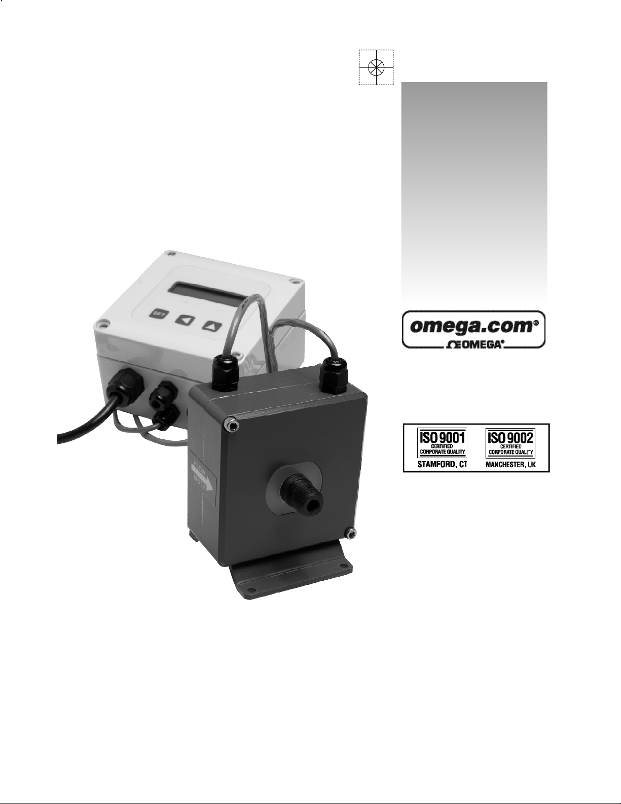
User’s Guide
FMG200 SERIES
Low-Flow Magnetic Flow Meter
Page 2

Servicing North America:
U.S.A.: One Omega Drive, P.O. Box 4047
ISO 9001 Certified
Stamford, CT 06907-0047
TEL: (203) 359-1660 FAX: (203) 359-7700
e-mail: info@omega.com
Canada: 976 Bergar
Laval (Quebec) H7L 5A1, Canada
TEL: (514) 856-6928 FAX: (514) 856-6886
e-mail: info@omega.ca
For immediate technical or application assistance:
U.S.A. and Canada: Sales Service: 1-800-826-6342 / 1-800-TC-OMEGA
®
Customer Service: 1-800-622-2378 / 1-800-622-BEST
®
Engineering Service: 1-800-872-9436 / 1-800-USA-WHEN
®
TELEX: 996404 EASYLINK: 62968934 CABLE: OMEGA
Mexico: En Espan˜ol: (001) 203-359-7803 e-mail: espanol@omega.com
FAX: (001) 203-359-7807 info@omega.com.mx
Servicing Europe:
Benelux: Postbus 8034, 1180 LA Amstelveen, The Netherlands
TEL: +31 (0)20 3472121 FAX: +31 (0)20 6434643
Toll Free in Benelux: 0800 0993344
e-mail: sales@omegaeng.nl
Czech Republic: Frystatska 184, 733 01 Karviná, Czech Republic
TEL: +420 (0)59 6311899 FAX: +420 (0)59 6311114
Toll Free: 0800-1-66342 e-mail: info@omegashop.cz
France: 11, rue Jacques Cartier, 78280 Guyancourt, France
TEL: +33 (0)1 61 37 2900 FAX: +33 (0)1 30 57 5427
Toll Free in France: 0800 466 342
e-mail: sales@omega.fr
Germany/Austria: Daimlerstrasse 26, D-75392 Deckenpfronn, Germany
TEL: +49 (0)7056 9398-0 FAX: +49 (0)7056 9398-29
Toll Free in Germany: 0800 639 7678
e-mail: info@omega.de
United Kingdom: One Omega Drive, River Bend Technology Centre
ISO 9002 Certified
Northbank, Irlam, Manchester
M44 5BD United Kingdom
TEL: +44 (0)161 777 6611 FAX: +44 (0)161 777 6622
Toll Free in United Kingdom: 0800-488-488
e-mail: sales@omega.co.uk
OMEGAnet®Online Service Internet e-mail
omega.com i n f o @ o m e g a . c o m
It is the policy of OMEGA Engineering, Inc. to comply with all worldwide safety and EMC/EMI
regulations that apply. OMEGA is constantly pursuing certification of its products to the European New
Approach Directives. OMEGA will add the CE mark to every appropriate device upon certification.
The information contained in this document is believed to be correct, but OMEGA accepts no liability for any
errors it contains, and reserves the right to alter specifications without notice.
WARNING: These products are not designed for use in, and should not be used for, human applications.
Page 3

TABLE OF CONTENTS
General Information
Features, Specications, Flow Range ................................................................................................. Page 1
Installation and Operation
Mounting, Connections, Grounding, Display, Outputs, Mounting Diagrams ........................................
Connections and Grounding
Flow Meter, Display Board, Ideal Grounding with Metallic Piping, Standard Grounding ..................... Page 3
Settings
Set-Up .................................................................................................................................................. Page 4
Troubleshooting
Problems, Probable Causes, Things to Try ......................................................................................... Page 5
TABLES, DIAGRAMS & CHARTS
. Page 2
Features ................................................................................................................................................ Page 1
Specications ........................................................................................................................................ Page 1
Flow Range ........................................................................................................................................... Page 1
Mounting Diagrams ............................................................................................................................... Page 2
Standard Connections and Grounding Diagrams ................................................................................. Page 3
Settings Diagrams ................................................................................................................................. Page 4
Troubleshooting Problems, Probable Causes, Things to Try ................................................................ Page 5
Page 4

GENERAL INFORMATION
The FMG200 is a small electromagnetic low-ow owmeter with
chemically-resistant plastic wetted parts and platinum electrodes
suitable for use with a variety of chemicals. Capable of measur-
ing pulsating ows from diaphragm-type metering pumps, it is
designed primarily for electrically-conductive chemical injection
applications. The 1/4” and 3/8” sizes monitor maximum ows
of 1 and 3 gallons per minute (or 4 and 11 L/min), respectively.
Barb or NPT ttings are available, and must be designated at
FEATURES
Captive plastic cover screw (4)
(mounting screws inside)
Backlit LCD display
(16 characters x 2 lines)
Keypad switches, tactile
Polycarbonate housing
Power cord
Connector (2)
for optional output cables
Connector (2)
for sensor cables
SPECIFICATIONS*
time of order.
The FMG200 is 115 Vac, 60 Hz powered and includes a rate and
total display as well as a variety of outputs. For continuous trans-
mission of a ow signal, there is a 4-20 mA output, a 0-5 volt signal,
and a frequency signal proportional to ow. In addition, there are
relay alarm outputs for user-set low and high ow levels.
Display
6 ft. control cables (2)
out to display
Fusion coated
aluminum housing
PVDF plastic ttings (2)
(must be designated at time of order)
Flow
Meter
Male NPT or barb
10-24 grounding screws
(on bottom of meter)
Removable bracket
for mounting
Materials Meter Housing
Electrodes
O-Ring
Display Housing
Rate Display Units
Total Display Units
Power
Accuracy
Max Fluid Temperature
Maximum Pressure
Minimum Conductivity
Outputs
*Specifications subject to change
Fusion coated aluminum
Platinum
FKM (EPDM optional)
Polycarbonate
Gal/Minute, Liters/Second, Gal/Hour
Gallons, Liters
115 Vac, 60 Hz
+/-1% of reading,
plus .005 gpm (0.02 lpm)
185˚ F (85˚ C)
150 psi (@ 75˚ F)
>20 microSiemens/cm
• 4-20 mA, 0-5 Volts, both isolated
• Frequency to 9999 pulses per gallon, isolated (10 mA, 30 Vdc)
• High alarm, low alarm relay, isolated (100 mA, 110 Vac/Vdc)
FLOW RANGE
SIZE LOW FLOW CUTOFF MINIMUM FLOW for spec accuracy MAXIMUM FLOW
L/MIN GAL/MIN GAL/HR L/MIN GAL/MIN GAL/HR L/MIN GAL/MIN GAL/HR
-025
.04 .01 .60 .26 .07 4.2 3.8 1 60
-038
.11 .03 1.80 .76 0.2 12 11 3 180
Page 1
Page 5

INSTALLATION and OPERATION
.218” DIA
3.75”
3.00”
2.50”
3.00”
3.50”
4.90”
2.30”
4.40”
4.93”
SET
.71”
.59”
1.25” 1.25” 1.25”
1.00”
4.93”
2.92”
INSTALLATION
Mounting. Mount the display housing to a secure surface with
screws or bolts. Remove the front cover to gain access to the
mounting holes, directly under the front cover screws. Attach
the ow meter to a secure surface using the foot bracket.
Alternatively, the unit can be supported by the piping and the
foot bracket removed. See mounting diagrams below.
CAUTION: Although this meter has an
empty pipe detection function, under
certain conditions of empty or partiallyfull pipe the meter may read
a ow when there is none. If this is a
hazardous condition, mount the meter in such a way as
to ensure the meter will always be full of liquid.
FLOW METER
CONNECTIONS
The meter ships with the coil activation and signal leads
already connected to the display housing. To connect optional
output signal or alarm relay leads, remove the front cover. See
the Connections diagram, page 3. Power connection uses a
standard power cord. If conduit connection is required, remove
the cord and strain relief and use the strain relief hole for a
conduit connector.
Grounding. For proper operation, one or both of the ground
lugs must be well connected to a good quality earth ground.
(The ground lugs also retain the foot bracket). See the
Grounding diagrams, page 3. The meter comes with a 12 foot
ground wire attached.
OPERATION
Display. The ow rate is displayed in the time and volume
units that have been selected in Set-Up (page 5) (liters/min, for
example). The cumulative total ow is displayed in the chosen
units, up to eight digits. When the total reaches its maximum,
the display resets to zero and begins again.
DISPLAY
6 ft. cables
to display
Outputs. The analog output varies continuously with the ow.
If the output is too “jumpy” (changes too frequently), it can be
damped in one of two ways: 1) increase the averaging time
(under the Fast Analog Output setting); or 2) select “Disabled”
(the default condition) under Fast Analog Output and increase
the amount of damping using the Low Pass Filter setting.
The pulse output will produce a 50% duty cycle pulse at the
volume intervals for which it is set - one pulse per liter, for
example. Note: Since each pulse consists of equal times on
and off, if the interval between pulses is large, the pulse may
remain in the “on” condition for several seconds.
The relay alarm output will only energize if the ow goes
above (high) or below (low) the ow alarm setting. The alarm
relay will remain energized until the ow exceeds the setpoint
by .25% (hysteresis).
Page 2
Page 6

- +
Pulse
Output
(UNUSED)
+
+
-
-
Power
Supply
4-20mA Output
(Consult Factory for Other Ranges
)
Strain Reliefs
and Housing Front
are Not Shown
Fuse, .25 AMP,
5 X 20mm
Low Alarm
High Alarm
Display
Cable
To
Sensor
110 Vac
110 Vac
G
Analog Device
CONNECTIONS and GROUNDING
WHITE
GREEN
BLACK
RED
To
Sensor
FLOW METER
DISPLAY BOARD
IDEAL GROUNDING WITH METALLIC PIPING
Bare End Under Clamp
Mounting Bracket Removed
To Earth Ground
STANDARD GROUNDING
Mounting Bracket
Connect Ground to
Either Screw
To Earth Ground
Page 3
Page 7

SETTINGS
D I S P L A Y
Rate
Tot
SET
Volume Units G
SET
Time Units M
SET
Tot Dec Point
Format 0.0
SET
An. output Type
SET-UP. Use the instructions below to set up your control. Use the key to move from one operation to
SET
the next, and use the and keys as described to change settings within operations.
This is the power-up display.
Rate/total display (shows two seconds after power-up), Press to begin programming.
SET
Use the key to choose the volume units: milliliters (mL) liters (L) or gallons (G)
Use the key to choose the time base for rate: per second (S), per minute (M), per hour
(H), per day (D).
Use the key to choose number of decimal places: 0, 0.0, 0.00.
Leave “Analog Output Type” unchanged unless you intend to use the 0-5 V output.
Standard setting is for 4-20 mA. Consult factory for 0-5 V output.
SET
Fast An. Output
SET
Rate For Analog
Output:
SET
SET
Rate For High
Alarm:
SET
Rate For Low
Alarm:
SET
Pulse Output
SET
Low Pass
Digital Filter:
SET
Totalizer Reset
Leave default (“Fast Analog Output”) unchanged unless you have a demanding closed-loop application.
Standard setting is “disabled”. If you enable this output, use the key to select a response
time, 50 to 1000 milliseconds. This will control how rapidly the analog output tracks ow.
Use the and key to set the percentage of full scale at which peak analog output
(20 mA or 5 V) occurs. On a max 10 gpm meter, 60% would be 6 gpm, for instance.
Use the and key to set the percent of full scale at which the high ow alarm will energize.
On a 10 gpm meter, 90% would equal 9 gpm, for instance.
Use the and key to set the percent of full scale at which the low ow alarm will
energize. On a 10 gpm meter, 10% would equal 1 gpm, for instance.
Use the and key to set the number of pulses (0000 to 9999) per unit. If you have
selected liters, it will be pulses per liter, etc.
This setting controls the smooth/responsive trade off of the display. Increasing the time makes
the display smoother, but slower to respond to change. Use the to set 1, 2, 5, 10, or 20 seconds.
If using the meter with pulsing ows, it may be necessary to increase the time.
Use the key to switch between totalizer reset “Enabled” and “Disabled”. If the reset is enabled,
every time the key is pressed during normal operation, the totalizer will reset to zero. Settings
nished.
SET
Page 4
Page 8

TROUBLESHOOTING
Problem
No Display
Flow rate always reads “0”
Flow rate incorrect
Probable Causes Try...
No power
Blown fuse
Loose ribbon cable
Reversed ow direction
Missing ground wire
Empty pipe
Flow rate below minimum
Loose wiring or incorrect wiring
Fluid conductivity <20 microSiemens/cm
Missing or incorrect ground wire
Fluid conductivity <20 microSiemens/cm
Empty pipe
Check for 110 Vac
Test fuse, replace if bad
Check ribbon cable connections
Reverse ow connections
Install ground wire
Install meter in vertical position
Use next smaller ow meter
Check connections on display board
Select another ow meter
Check for proper grounding
Select another ow meter
Install meter in vertical position
Page 5
Page 9

WARRANTY/DISCLAIMER
OMEGA ENGINEERING, INC. warrants this unit to be free of defects in materials and workmanship for a
period of 13 months f rom date of purchase. OMEGA’s WARRANTY adds an additional one (1) month
grace period to the normal one (1) year product warranty to cover handling and shipping time. This
ensures that OMEGA’s customers receive maximum coverage on each product.
If the unit malfunctions, it must be re t u rned to the factory for evaluation. O M E G A’s Customer Serv i c e
D e p a rtment will issue an Authorized Return (AR) number immediately upon phone or written re q u e s t .
Upon examination by OMEGA, if the unit is found to be defective, it will be re p a i red or replaced at no
c h a rge. O M E G A’s WARRANTY does not apply to defects resulting from any action of the purc h a s e r,
including but not limited to mishandling, improper interfacing, operation outside of design limits,
i m p roper re p a i r, or unauthorized modification. This WARRANTY is VOID if the unit shows evidence of
having been tampered with or shows evidence of having been damaged as a result of excessive corro s i o n ;
or current, heat, moisture or vibration; improper specification; misapplication; misuse or other operating
conditions outside of OMEGA’s c o n t rol. Components in which wear is not warranted, include but are not
limited to contact points, fuses, and triacs.
OMEGA is pleas ed to offer suggestions on the use of its various products. However,
OMEGA neither assumes responsibility for any omissions or errors nor assumes liability for any
damages that result from the use of its products in accordance with information provided by
OMEGA, either verbal or written. OMEGA warrants only that the parts manufactured by the
company will be as specified and free of defects. OMEGA MAKES NO OTHER WARRANTIES OR
R E P R E S E N TATIONS OF ANY KIND WHATSOEVER, EXPRESSED OR IMPLIED, EXCEPT THAT OF
TITLE, AND ALL IMPLIED WARRANTIES INCLUDING ANY WARRANTY OF MERCHANTA B I L I T Y
AND FITNESS FOR A PA RTICULAR PURPOSE ARE HEREBY DISCLAIMED. LIMITATION OF
L I A B I L I T Y: The remedies of purchaser set forth herein are exclusive, and the total liability of
OMEGA with respect to this ord e r, whether based on contract, warr a n t y, negligence,
indemnification, strict liability or otherwise, shall not exceed the purchase price of the
compone nt upon which lia bili ty is b ased. In no even t shal l OMEG A be li able for
consequential, incidental or special damages.
CONDITIONS: Equipment sold by OMEGA is not intended to be used, nor shall it be used: (1) as a “Basic
Component” under 10 CFR 21 (NRC), used in or with any nuclear installation or activity; or (2) in medical
applications or used on humans. Should any Product(s) be used in or with any nuclear installation or
a c t i v i t y, medical application, used on humans, or misused in any way, OMEGA assumes no re s p o n s i b i l i t y
as set forth in our basic WA R R A N TY/ DISCLAIMER language, and, additionally, purchaser will indemnify
OMEGA and hold OMEGA h a rmless from any liability or damage whatsoever arising out of the use of the
P roduct(s) in such a manner.
RETURN REQUESTS/INQUIRIES
Direct all warranty and repair requests/inquiries to the OMEGA Customer Service Department. BEFORE
RETURNING ANY PRODUCT(S) TO OMEGA, PURCHASER MUST OBTAIN AN AUTHORIZED RETURN
(AR) NUMBER F R O M OMEGA’S CUSTOMER S E RVIC E D E PA RT MENT (IN OR D E R T O AV O I D
PROCESSING DELAYS). The assigned AR number should then be marked on the outside of the return
package and on any correspondence.
The purchaser is responsible for shipping charges, freight, insurance and proper packaging to prevent
breakage in transit.
FOR WARRANTY RETURNS, please have the
following information available BEFORE
contacting OMEGA:
1 . P u rchase Order number under which the pro d u c t
was PURCHASED,
2. Model and serial number of the product under
warranty, and
3. Repair instructions and/or specific problems
relative to the product.
FOR NON-WARRANTY REPAIRS,
consult OMEGA
for current repair charges. Have the following
information available BEFORE contacting OMEGA:
1. Purchase Order number to cover the COST
of the repair,
2. Model and serial number of the product, and
3. Repair instructions and/or specific problems
relative to the product.
OMEGA’s policy is to make running changes, not model changes, whenever an improvement is possible. This affords
our customers the latest in technology and engineering.
OMEGA is a registered trademark of OMEGA ENGINEERING, INC.
© Copyright 2005 OMEGA ENGINEERING, INC. All rights reserved. This document may not be copied, photocopied,
reproduced, translated, or reduced to any electronic medium or machine-readable form, in whole or in part, without the
prior written consent of OMEGA ENGINEERING, INC.
Page 10

W h e re Do I Find Eve rything I Need for
P rocess Measurement and Control?
OME GA…Of Cours e !
Shop online at omega.com
T E M P E R AT U R E
Thermocouple, RTD & Thermistor Probes, Connectors, Panels & Assemblies
Wire: Thermocouple, RTD & Thermistor
Calibrators & Ice Point References
Recorders, Controllers & Process Monitors
Infrared Pyrometers
PRESSURE, STRAIN AND FO RC E
Transducers & Strain Gages
Load Cells & Pressure Gages
Displacement Transducers
Instrumentation & Accessories
F LOW / L E V E L
Rotameters, Gas Mass Flowmeters & Flow Computers
Air Velocity Indicators
Turbine/PaddlewheelSystems
Totalizers & Batch Controllers
p H / C O N D U C T I V I TY
pH Electrodes, Testers & Accessories
Benchtop/Laboratory Meters
Controllers, Calibrators, Simulators & Pumps
Industrial pH & Conductivity Equipment
DATA AC Q U I S I T I O N
Data Acquisition & Engineering Software
Communications-Based Acquisition Systems
Plug-in Cards for Apple, IBM & Compatibles
Datalogging Systems
Recorders, Printers & Plotters
H E AT E R S
Heating Cable
Cartridge & Strip Heaters
Immersion & Band Heaters
Flexible Heaters
Laboratory Heaters
E N V I RO N M E N TA L
M O N I TORING AND CONTRO L
Metering & Control Instrumentation
R e f r a c t o m e t e r s
Pumps & Tubing
Air, Soil & Water Monitors
Industrial Water & Wastewater Treatment
pH, Conductivity & Dissolved Oxygen Instruments
LT-13212-C
02/18/11
M-4173/0211
 Loading...