

Page 1
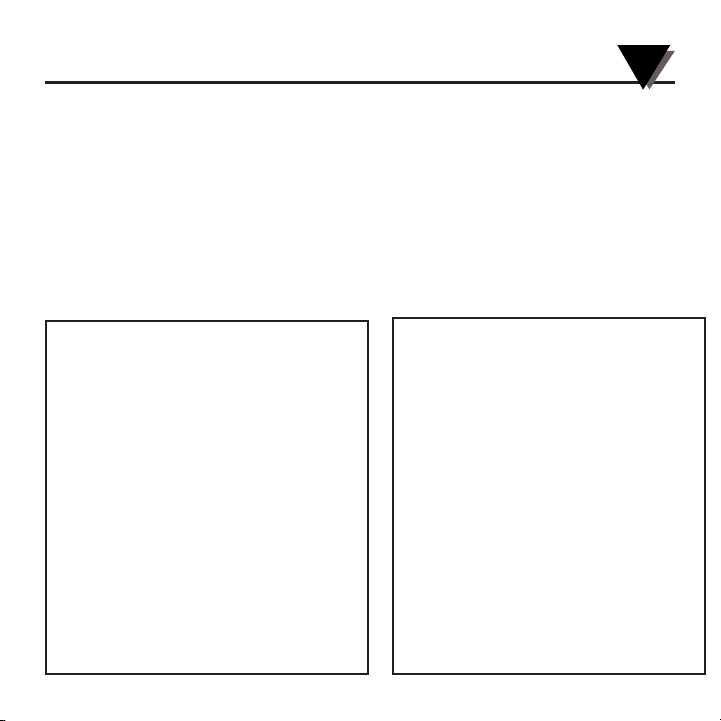
FMA-700A SERIES Mass Flow Controllers
FMA-800A SERIES Mass Flowmeters
omega.com
e-mail: info@omega.com
For latest product manuals:
omegamanual.info
User’s Guide
Shop online at
Page 2
OMEGAnet®On-Line Service Internet e-mail
omega.com info@omega.com
It is the policy of OMEGA Engineering, Inc. to comply with all worldwide safety and EMC/EMI regulations that apply. OMEGA is constantly pursuing
certification of its products to the European New Approach Directives. OMEGA will add the CE mark to every appropriate device upon certification.
The information contained in this document is believed to be correct, but OMEGA accepts no liability for any errors it contains, and reserves
the right to alter specifications without notice.
WARNING: These products are not designed for use in, and should not be used for, human applications.
Benelux:
Postbus 8034, 1180 LA Amstelveen
The Netherlands
Tel: +31 (0)20 3472121 FAX: +31 (0)20 6434643
Toll Free in Benelux: 0800 0993344
e-mail: sales@omegaeng.nl
Czech Republic:
Frystatska 184, 733 01 Karvina
´, Czech Republic
Tel: +420 (0)59 6311899 FAX: +420 (0)59 6311114
Toll Free: 0800-1-66342 e-mail: info@omegashop.cz
France:
11, rue Jacques Cartier, 78280 Guyancourt, France
Tel: +33 (0)1 61 37 2900 FAX: +33 (0)1 30 57 5427
Toll Free in France: 0800 466 342
e-mail: sales@omega.fr
Servicing Europe:
U.S.A. and Canada:
Sales Service: 1-800-826-6342/1-800-TC-OMEGA
®
Customer Service: 1-800-622-2378/1-800-622-BEST
®
Engineering Service: 1-800-872-9436/1-800-USA-WHEN
®
U.S.A.: ISO 9001 Certified
One Omega Drive, Box 4047
Stamford, CT 06907-0047
Tel: (203) 359-1660
FAX: (203) 359-7700
e-mail: info@omega.com
Servicing North America:
For immediate technical or application assistance:
Mexico:
En Espan~ol: (001) 203-359-7803
FAX: (001) 203-359-7807
e-mail: espanol@omega.com
info@omega.com.mx
Germany/Austria:
Daimlerstrasse 26, D-75392
Deckenpfronn, Germany
Tel: +49 (0)7056 9398-0 FAX: +49 (0)7056 9398-29
Toll Free in Germany: 0800 639 7678
e-mail: info@omega.de
United Kingdom: ISO 9002 Cer
tified
One Omega Drive
River Bend Technology Centre
Northbank, Irlam
Manchester M44 5BD United Kingdom
Tel: +44 (0)161 777 6611 FAX: +44 (0)161 777 6622
Toll Free in United Kingdom: 0800-488-488
e-mail: sales@omega.co.uk
Canada:
976 Bergar
Laval (Quebec) H7L 5A1, Canada
Tel: (514) 856-6928
FAX: (514) 856-6886
e-mail: info@omega.ca
Page 3

i
TABLE OF
CONTENTS
FMA-700A Series Mass Flow Controllers
FMA-800A Series Mass Flowmeters
Page
Section 1 Introduction . . . . . . . . . . . . . . . . . . . . . . . . . . . . . . 1
1.1 General Description .............................................................................. 2
1.2 System Features ..................................................................................... 3
Section 2 Specifications . . . . . . . . . . . . . . . . . . . . . . . . . . . . . 4
2.1 for Series FMA-800A MFM’S ............................................................... 5
2.1 for Series FMA-700A MFC’S ................................................................ 5
Section 3 Installation and Operating Procedures . . . . . . . . . . 6
3.1 General Information ............................................................................. 6
3.2 Gas Connections ................................................................................... 6
3.3 System Purging....................................................................................... 7
3.4 External Electrical Connector-9-Pin D-Connector............................. 7
3.5 Basic Operating Procedures to Establish a Controlled Flow Rate .. 9
3.6 Additional Features - Connections and Operations
Valve Override (SIM-VO) for Series FMA-700A MFC.................. 9
3.7 Reference Voltage (VREF) .................................................................. 10
3.8 Digital Interfacing ................................................................................10
Section 4 Theory of Operation . . . . . . . . . . . . . . . . . . . . . . . 11
4.1 Theory of Operation ............................................................................ 11
4.2 Mass Flowmeter/Mass Flow Controller Electronics ...................... 14
4.3 Control of the Proportional Control Valve ...................................... 16
Section 5 Maintenance . . . . . . . . . . . . . . . . . . . . . . . . . . . . 17
5.1
General ............................................................................................................17
5.2 Preliminary Checks ........................................................................................... 17
5.3 Control Valve Disassembly ............................................................................ 17
Page 4

ii
TABL E OF
CONTENTS
FMA-700A Series Mass Flow Controllers
FMA-800A Series Mass Flowmeters
Page
Section 5 Maintenance continued
5.4 System Troubleshooting .................................................................................. 18
5.5 Return Shipments
.......................................................................................................... 18
Section 6 Calibration . . . . . . . . . . . . . . . . . . . . . . . . . . . . . . 19
6.1 General Description ............................................................................ 19
6.2 Equipment Required............................................................................ 19
6.3 Calibration Procedure ......................................................................... 19
Section 7 Input/Output (I/O) Designations & Electrical
Specifications. . . . . . . . . . . . . . . . . . . . . . . . . . . . . . . 24
7.1 Input/Output (I/O) Designations (Electrical Connections) .......... 24
7.2 I/O Electrical Specifications .............................................................. 25
7.3 Simple Valve Override (SIM-VO) ...................................................... 27
Section 8 Current Loop Specifications. . . . . . . . . . . . . . . . . . 28
Section 9 Gas Conversion Factors . . . . . . . . . . . . . . . . . . . . 30
Page 5

EXPLODED VIEW
SERIES FMA-700A MASS FLOW CONTROLLER
INTRODUCTION
1
(Model FMA-761A-V Illustrated)
1
Page 6

INTRODUCTION
1
2
1.1 General Description
OMEGA’s Mass Flow Products reflect over three decades of experience in the design and
manufacture of precision instruments for the measurement and control of gas flow.
OMEGA’s Mass Flow products incorporate design principles that are simple and
straightforward, yet flexible enough to operate under a wide variety of process
parameters. The result is mass flowmeters (MFM’s), mass flow controllers (MFC’s) that
are accurate, reliable and cost-effective solutions for many mass flow applications.
OMEGA’s Series FMA-800A and Series FMA-700A accurately measure (Series FMA700A/800A) and control (Series FMA-700A) flow rates of a wide variety of gases from 5
standard cubic centimeters per minute (SCCM) to 1000 standard liters per minute (SLM)
full scale nitrogen flow for operating pressures up to 1500 PSIG. The MFM’s and MFC’s
provide a linear flow signal output proportional to a calibrated flow rate. This output
signal can be used to drive a digital display, such as the DPF60 Series, or other customer
supplied data acquisition equipment.
The Series FMA-800A MFM’s & FMA-700A MFC’s incorporate an operating principle
based on the thermodynamic properties of the process gas being monitored. Both the
FMA-800A MFM’S & FMA-700A MFC’s employ a sensor assembly that includes a heater
and two precision resistance-type temperature sensors. The integral printed circuit board
(PCB) assembly performs amplification and linearization of the sensor assembly output
signal and provides the flow signal output. Patented, restrictive laminar flow elements
condition the main channel of gas flow while thermal measurement occurs in the gas
flowing through the bypass sensor assembly. The FMA-700A additionally incorporate an
integral proportional control valve and closed loop control circuitry on the PCB assembly.
Detailed explanation of operational theory is described in Section 4, Theory of Operation.
Page 7

INTRODUCTION
1
1.2 System Features
+ Single Power Supply Operation
Voltage output models operate from nominal power supply voltages of + 12 (±5%) or +
15 (±10%) Vdc. Current loop models operate from nominal power supply voltages of + 15
(±5%) or + 24 (±15%) Vdc. The voltage output models may be directly connected into
existing installations having dual power supply voltages of ±15 Vdc with no change in
performance and no modification to the installation to accept the new MFM/MFC.
+ 4-20 mAdc Operation
4-20 mAdc current loop model is sinking current loop current flow.
+ Fast Response
Control circuitry significantly reduces “dead time” when ramping from no (i.e. zero) flow
conditions and improves MFC response time.
+ Absolute Zero (ABZ)
When the flow is detected to be less than 1.5% of of full scale, ABZ circuitry automatically
clamps the flow signal output to zero, eliminating flow signal zero drift.
Duringcalibration, the ABZ feature is disabled by means of a control input at the I/O
connector (refer to Section 7, Input/Output [I/O} Designations [Electrical Connections]
and I/O Electrical Specifications for details).
+ Internal Voltage Regulation and Temperature Compensation Circuits
Stabilizes flow signal output, flow signal accuracy and closed loop control during
transitional conditions, regardless of power supply and temperature fluctuations.
3
Page 8
4
+ Attitude Insensitivity
MFM’s and MFC’s may be mounted in any position and are able to maintain tight
accuracy specifications with stable control.
+ Laminar Flow Element Package
Computer-determined for each specific application based on flow rate and the physical
properties of the process gas.
+ Valve Override (SIM-VO)
The automatic closed loop control may be temporarily defeated to force the control valve
fully open during system or process diagnostics.
2
SPECIFICATIONS
2.1 Specifications
Specifications for Series FMA-800A MFM’s and Series FMA-700A MFC’s
Response Time (per SEMI E17-91 Setting Time): 1 to 2 seconds
Accuracy and Linearity: +/-1% full scale (≤500 SLM N
2
).
+/-1.5% full scale (>500 SLM N
2
).
Repeatability: Within ±0.2% full scale at any constant
temperature within operating
temperature range.
INTRODUCTION
1
Page 9
5
SPECIFICATIONS
2
2.1 Specifications (Con’t)
Specifications for Series FMA-800A MFM’s and Series FMA-700A MFC’s
Rangeability (Control Range): 50:1 (2% - 100% full scale)
(accuracy and control)
Ambient and Operating Temperature Range: -10 to 70°C (+ 14 to 158°F)
Temperature Coefficient (per SEMI E18-91 Zero
Effect and Span Effect): ± 0.05% full scale/°C of zero
± 0.05% of reading/°C of span
Pressure Coefficient (per SEMI E28-92 Total
Calibration Effect): ± 0.1% atmosphere typical using nitrogen (N
2
)
Setpoint Input / Flow Signal Output:
Setpoint Input Flow Signal Output
0-5 Vdc 0-5 Vdc (2K ohm
minimum load resistance
1-5 Vdc 4-20 mAdc (refer to load
resistance values **
Load resistance values for 4-20 mAdc flow
signal output:
0-450 ohms for 6.5 -15 Vdc loop supply
voltage
200 -750 ohms for 15-30 Vdc loop supply
voltage
Power Supply Requirements
(Current consumption <45 mAdc for MFM’s
250 mAdc for MFC’s:
Voltage output models:
+12 (±5%)
+15 (±10%) Vdc
Current loop models
+ 15 (±5%) or +24 (±15%) Vdc
Mounting Orientation: Attitude insensitive
Warm-up Time: 10 minutes
External Electrical Connector:
Nine (9) - pin D-connector
Page 10

3
INSTALLATION AND OPERATING PROCEDURES
3.1 General Information
OMEGA’s Series FMA-800A MFM’s and Series FMA-700A MFC’s must be installed in a
clean, dry area with adequate space surrounding the MFM/MFC for ease of
maintenance. Ambient temperature should not exceed the specific operating range of -10
-70°C (14-158°F). The MFM's/MFC's are attitude insensitive, therefore, may be mounted
in any position. Users may specify factory calibration in the exact attitude of the
installation. Users must specify process gas, flow range, inlet pressure, outlet pressure
(for FMA-700A), operating temperature and calibration standard at the time of ordering.
When supplying a MFC, OMEGA Engineering will computer-calculate the appropriate
value orifice for the application based on the user-specified operating parameters.
3.2 Gas Connections
Each MFM/MFC has two (2) threaded process connection ports, one (1) located at each
end of the base block. One (1) serves as the gas inlet while the other is the gas outlet. For
compression fittings, make certain the tubing which mates to the fitting is correctly sized,
clean and is seated against the shoulder in the body of the compression fitting, prior to
tightening the connection. Tighten the fittings hex nut sufficiently to prevent leakage. For
face seal fittings, exercise caution so as not to damage the face seal sealing surfaces.
Whether using compression or face seal fittings , refer to the applicable fitting
manufacturer’s data for specific recommendations regarding installation and tightening.
Test joints for leaks. The inlet connection contains a 325 mesh (44 micron) filter
screenwhich prevents foreign matter from entering the instrument. Refer to System
Purging for additional recommendations.
6
Page 11

INSTALLATION AND OPERATING PROCEDURES
3
7
3.3 System Purging
To eliminate contamination from foreign materials, start-up cleaning is highly
recommended prior to MFM/MFC installation. Start-up cleaning must remove weld
debris, tube scale and any loose particulate generated during system fabrication.
If corrosive gases or reactive gases are to be used. the complete gas handling system must
be purged to remove all air before introducing process gas into the system. Purging can
be accomplished with dry nitrogen or other suitable inert gases.
Also, if it becomes necessary to break any gas connection exposing the gas handling
system to air, all traces of corrosive or reactive gas must be purged from the system
before breaking the connection.
Never allowing a corrosive or reactive process to mix with air reduces the chance of
particulate or precipitate formation in the gas handling system.
3.4 External Electrical Connector - 9-Pin D - Connector
Please note the two (2) “common” references noted in the text. SIGNAL COMMON
(pin 4) is a zero current return reference for all functional circuit modules. POWER
COMMON/0 VDC (pin 8) is the separate return for the proportional control valve
operating current and all other circuit currents.
Figures 3-1 and 3-2 diagram the external electrical connections to be made to the FMA800A MFM’s and FMA-700A MFC’s. A separate control valve common wire, connected to
POWER COMMON/0 VDC (pin 8) is illustrated and required. This connection keeps the
high current related to the control valve independent of the more sensitive, low level,
processing circuitry, thus avoiding potential noise problems and/or ground loops.
Page 12
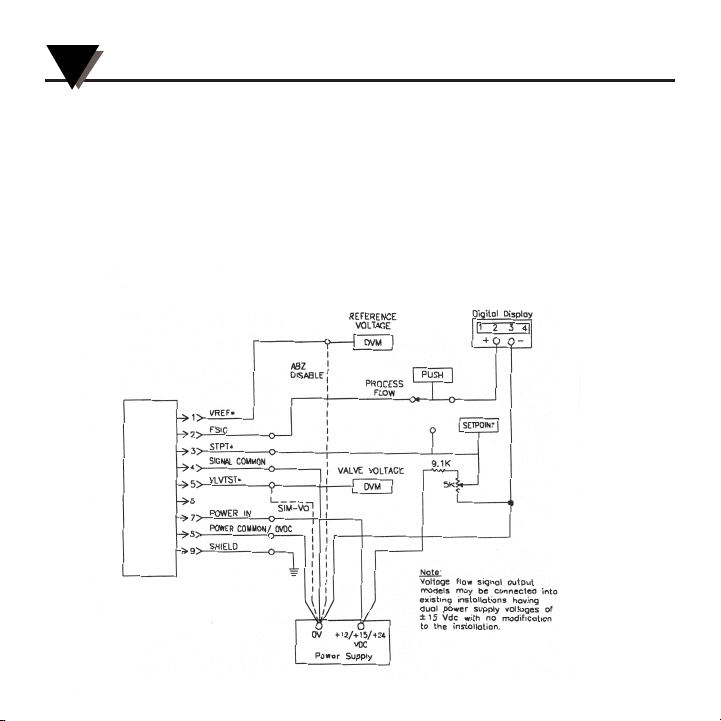
3.4 External Electrical Connector - 9-Pin D - Connector (Con’t)
For Models having a 0-5 Vdc Flow Sgnal Output, Figure 3-1 also illustrates the circuit
arrangement for a typical user-provided setpoint control. As an alternative OMEGA
offers the FMA-78P Series Interface Modules.
Refer to Section 7, Input/Output (I/O) Designations (Electrical Connections) & I/O
Electrical Specifications, for more details of the individual pin functions for the 9-pin Dconnector. See Section 8, Current Loop Specification, for details on current loop operation.
❋ = No connection required
for Series FMA-800A MFM
SERIES FMA-800 MASS FLOWMETER
OR
SERIES FMA-700 MASS FLOW CONTROLLER
8
INSTALLATION AND OPERATING PROCEDURES
3
Figure 3-1 External Electrical Connections for
Series FMA-800A MFM’s and Series FMA-700A MFC’s
For Models having a 0-5 Vdc Flow Sgnal Output
Page 13
9
INSTALLATION AND OPERATING PROCEDURES
3
Page 14

3.5 Basic Operating Procedures to Establish a Controlled
Flow Rate
To operate the FMA-700A MFC after electrically connecting the MFC to the interface
module or other secondary electronics, introduce power to the system, allowing a ten (10)
minute warm-up period prior to operation. Adjust SETPOINT to zero flow rate. Turn on
te gas supply, being careful to avoid presure surges by bringing the MFC gradually up to
the actual operating conditions. Adjust the SETPOINT to the desired flow rate.
3.6 Additional Features - Connections and Operations
Valve Override (SIM-VO) for FMA-700A
Pin 5 of the 9-pin D-connector is designated VLVTST and has dual functions, both of them
accessible by employing a diagnostic kit (breakout board) function. When connected to a
digital voltmeter, pin 5 provides measurement of the valve voltage driving the opening
and closing of the proportional control valve during closed loop control. When pin 5 is
instead connected to the POWER COMMON/0 VDC, pin 8). the SIM-VO (simple valve
override) function is activated and the proportional control valve is driven full open.
When using mechanical switches to provide the SIM-VO action, momentary push-button
switches are preferable. If toggle switches are used, they should have a second set of
contacts connected to a power source and a VALVE STATUS indicator. When operating,
the VALVE STATUS indicator will remind the operator the valve override switch must be
turned to automatic control operation. Mechanical switch contacts should be of a type
appropriate for use in “dry” circuit applications. These contacts are usually gold or
gold plated.
10
INSTALLATION AND OPERATING PROCEDURES
3
Page 15

3.7 Reference Voltage (VREF) (Only on voltage output models)
Pin 1, VREF, has dual functions. When connected to a digital voltmeter. pin 1 provides a
reference voltage measurement. The reference voltage may be adjusted to a +5 Vdc
reading the digital voltmeter and adjusting the VREF trimpot located on the PC board
(with 9-pin D-connector on right, far right trimpot in row of four trimpots at top of PC
board assembly). The reference voltage may then be used in a simple system to provide a
constant setpoint control. The reference voltage is stable under temperature changes and
power supply fluctuations. A simple voltage divider (i.e. command potentiometer) with a
minimum load resistance of 5K ohm could be used where the constant setpoint would be
adjusted and fed into the setpoint input, pin 3 (STPT), of the 9-pin D-connector. Then,
upon power up, the controller would go to the setpoint for a constant flow.
When pin 1 is instead connected to the power common (power supply 0 Vdc or POWER
COMMON/0 VDC, pin 8), the ABZ function is disabled.
The ABZ disabled is only used in calibration or tr
oubleshooting procedures. Do not
operate the MFC for normal process control with ABZ disabled.
3.8 Digital Interfacing
When digital logic IC’s such as TTL or CMOS gates or drivers, etc., are used to interface
and external computer/controller with the FMA-700A MFC, it is important to observe
the logic level values required for proper and reliable operation. See details under Section
7, Simple Valve Override (SIM-VO).
NOTE
11
INSTALLATION AND OPERATING PROCEDURES
3
Page 16

4.1 Theory of Operation
OMEGA’s Series FMA-800A Mass Flowmeters (MFM’s) & Series FMA-700A Mass Flow
Controllers (MFC’s) incorporate an operating principle based on the thermodynamic
properties of the process gas being monitored.
Mass flow measurement relates to the amount of heat absorbed by the process gas. The
amount of heat the gas absorbs is determined by the gas’ molecular structure. Specific
heat, the amount of heat required to raise the temperature of one (1) gram of a particular
gas one degree centigrade (1°C), quantitatively describes this “thermal absorbency”.
Mass flow measurement consists of a bypass sensing tube with a heater wound around
the center of the sensing tube and precision resistance-type temperature sensor located
equidistant upstream and downstream of the heater. A laminar flow element package,
located in the main flowstream, acts as an appropriate restriction creating a pressure drop
forcing a fixed percentage of the total flow, approximately 10 SCCM, through the bypass
sensing tube for temperature differential detection. For example, if a MFM is calibrated for
a 1000 SCCM maximum flow, 10 SCCM would flow through the sensor assembly and 990
SCCM would flow through the laminar flow element assembly in the main flowstream.
Figure 4-1 illustrates the sensor assembly as a block diagram
Figure 4-1
Block
Diagram of
Sensor
Assembly
12
4
THEORY OF OPERATION
Page 17

4.1 Theory of Operations (Con’t)
Constant power heat input to the heater is supplied by a precision power supply on the PCB
assembly. Heat from the heater spreads uniformly from the center of the sensor tube. At a no
(i.e. zero) flow condition, the temperature at both the upstream and downstream
temperature sensor is equal. As gas flows through the sensing tube, heat is displaced to the
downstream temperature sensor creating a temperature differential between the upstream
and downstream temperature sensors. The upstream and downstream temperatures sensors
form two (2) legs of a bridge network at the sensors assembly inputs to the PCB assembly.
The resulting temperature differential is amplified on the PCB assembly to a user-specified
0-5 Vdc or 4-20 mAdc output signal directly proportional to gas mass flow rate.
Three (3) important factors have been noted thus far: specific heat, heat input, and
temperature differential. These three (3) factors help define a precise relationship to the mass
flow. Therefore, if the specific heat & heat input are known and in an acceptable range,
accurate temperature measurement will produce an accurate indication of flow rate for a
particular gas. To ensure an accurate flow measurement, flow disturbances must be
eliminated or greatly reduced. Accordingly, both the sensor tube and laminar flow. Actual
gas or gas factors are used in calibration to account for the specific heat of the monitored gas.
The upstream temperature sensor, downstream temperature sensor and heater are
connected to the PCB assembly via a miniature flexible interconnecting cable. These
components are shown in Figure 4-2.
Figure 4-2
Sensor Assembly
and
Electronic Printed
Circuit Board
13
THEORY OF OPERATION
4
Page 18

THEORY OF OPERATION
4
4.1 Theory of Operations (Con’t)
As previously mentioned, the laminar flow element package, acting as a flow restriction
creating the required pressure drop, is located in the main flowstream. The laminar flow
element package, in addition to forcing a fixed percentage of the total flow through the
bypass sensing tube, also determines the MFM’s/MFC’s maximum flow for which the
unit may be calibrated. Disc-like, individual flow elements comprise the laminar flow
element package. Each flow element has chemically-etched precision channels to restrict
flow. The MFM’s/MFC’s maximum flow rate determines both the size and quantity of
flow elements used. As few as one (1) and as many as three hundred (300) flow elements
may be required.
Figure 4-3 illustrates three (3) of the five (5) available sizes of the laminar flow elements.
The smallest flow element shown has only one (1) chemically-etched precision flow
channel and would be used as part of a laminar flow element package in a low flow
range MFM/MFC, for example Model FMA-800A MFM or Model FMA-700A MFC. In
comparison, the largest flow element shown contains numerous flow channels. Varying
the number of flow elements in the flow element package, using flow elements having
more flow channels, combinations of similarly-sized flow elements or a physically larger
flow element size would be used for the various available flow ranges. For example, a
flow element package containing multiple flow elements provides a large number of
parallel paths for gas flow, thereby obtaining a higher flow rate.
Figure 4-3
Laminar
Flow
Elements
14
Page 19

4.2 Mass Flowmeter/Mass Flow Controller Electronics
As briefly noted in Section 1, the PCB assembly performs three (3) general flowmeter
functions: amplification, linearization, and flow signal output. If the instrument under
discussion is an MFC, the required control circuitry to regulate a proportional control
valve is included on the PCB. Refer to Figure 4-4 for the block diagram of the Series
FMA-700A/800A MFM’s/MFC’s.
For a condition of no gas flow, both the upstream and downstream temperature sensors
are heated equally, giving both sensors the same temperatures and resistance values.
Therefore, the bridge network is balanced and the difference in voltage between each
sensing leg of the bridge network is zero. With no flow, the instruments flow signal
output is also zero. When gas flow does occur, the downstream temperature sensor
increases its resistance, in response to a higher temperature, with respect to the upstream
temperature sensor. A differential voltage is developed which is directly proportional to
the mass flow rate of the gas. The differential voltage signal, typically about 30 millivolts
(mV) maximum, is applied to the input of a precision instrument amplifier. The amplified
signal is then fed to linearization circuitry which corrects the temperature sensor bridge
network excitation voltage. The degree of correction is small, with subtle non-linearity
effect accommodated as the flow approaches its full range value.
The output signal from the instrument amplifier also drives a special signal-conditioning
amplifier, which is an output ABZ/meter driver/shaper stage. This multi-purpose stage
is an active differentiator network having a tailored rapid response characteristic. The
output flow signal must closely match the actual flow, even in transitional conditions of
the flow controller response to a changed setpoint command. The stage is adjusted until
the slower changing raw sensor flow signal is shaped to change in the same manner as
the actual gas flow changes. Figure 4-5 shows how this circuit’s signal closely duplicates
a step change and correspondingly rapid actual gas flow rate change. The second
purpose of this stage is to provide a user-specified 0-5 Vdc or 4-20 mAdc output signal
for a 0 to 100 percent of full scale flow rate.
15
THEORY OF OPERATION
4
Page 20

THEORY OF OPERATION
4
4.2 Mass Flowmeter/Mass Flow Controller Electronics (Con’t)
16
Figure 4-4 Block Diagram of Series FMA-800A Mass Flowmeters and
Series FMA-700A Mass Flow Controllers
Page 21

4.2 Mass Flowmeter/Mass Flow Controller Electronics (Con’t)
17
4.3 Control of the Proportional Control Valve
Closed-loop control of the proportional control valve adds circuitry to the MFC
schematic diagram not required for the MFM. The additional circuitry includes a setpoint
input channel, an analog comparator and a valve (power) driver stage. Generally
speaking, the closed-loop control system works as follows: the setpoint input signal is
compared with the flow signal output in the analog comparator stage. If the setpoint
input signal commands a flow change, comparison between the setpoint input signal and
the flow signal output is such that the analog comparator applies a signal of a given
magnitude and polarity to the valve driver stage causing the valve to respond to the flow
change. As this occurs, the flow signal output approaches and theoretically equals the
setpoint signal stabilizing the valve’s power drive signal, holding the valve in a relatively
stable position. Typical valve displacement (i.e. valve travel) for an MFC sized for 1
SLPM of nitrogen, an inlet pressure of 20 PSIG & an outlet pressure of 0 PSIG (14.7 PSIA),
is approximately 0.0003 inch for 0 to 100 percent of full scale flow.
Figure 4-5 Response Curve:
Comparison between Flow Signal and Actual Gas Flow
THEORY OF OPERATION
4
Page 22

5.1 GENERAL
Successful maintenance and troubleshooting depends upon the ability of the operator or
technician to associate a given symptom with the source of the problem. The more
familiar one is with the working of the MFM/MFC, the easier it is to make this
association. Carefully reading Section 4, Theory of Operation, is recommended to gain
this familiarity. Also, this knowledge will help in formulating troubleshooting procedures
for less common problems. The potential problems described in this section are more
general in nature. Should further assistance be required, contact the factory.
5.2 Preliminary Checks
When no specific cause of trouble is apparent , a good preliminary check is to make a
visual inspection of the MFM / MFC in the following areas:
• Check interconnecting cable assemblies for loose or broken wires.
• Inspect interconnecting cable assemblies for loose fit.
• Test fuse in the power supply for continuity.
• Remove the housing enclosing the PC board assembly and inspect for discolored or
charred components.
5.3 Control Valve Disassembly
Major maintenance procedures of cleaning and total MFC disassembly and recalibration
are typically done at the factory. However for simple maintenance, the following steps
explain how to disassemble the control valve for cleaning or service (refer to exploded
view of Series FMA-700A MFC):
a). If the valve is integral with the controller, disconnect the electrical connector.
b). Remove the hex nut from the top of the valve assembly and carefully remove the
cover/coil assembly.
c). Unscrew the valve stem and remove the valve stem and valve stem O-ring.
d). Remove the internal valve assembly. Do not change any shim positions.
e). Unscrew the orifice and remove the orifice and orifice O-ring.
f). Parts may be cleaned ultrasonically in a suitable solvent. The valve stem and orifice O-
rings should be replaced prior to reassembly.
g). Reassemble parts in reverse order.
h). Test MFC performance for smooth opening flows and stable control at setpoint.
18
5
MAINTENANCE
Page 23

19
5.4 System Troubleshooting
The system troubleshooting table shown below in table 5-1 indicates the steps to follow
after a physical check is completed. This table offers a cause and effect procedure aimed
at localizing the trouble to a particular section or system component.
5.5 Return Shipments
Contact OMEGA’s Customer Service for a return number if an MFM/MFC is to be
returned for any reason. The unit along with a Declaration of Contamination form and a
Material Safety Data Sheet, must accompany all return shipments. If the MFM/MFC was
used with corrosive or toxic gases, the customer is responsible for removing all traces of
hazardous materials prior to shipment. Detail the condition of purging used. OMEGA is
to be notified about application conditions before any MFM/MFC will be serviced. Items
must be properly packed and shipped prepaid.
Table 5-1 System Troubleshooting Chart
MAINTENANCE
5
Page 24

20
6.1 General
All OMEGA Series FMA-800A MFM’s and FMA-700A MFC’s are shipped calibrated to
the customer’s operating conditions within the tolerances given in the specifications
specified in Section 2. If service is required, including replacement of the PCB assembly,
recalibration may be required. The calibration section is general in nature and assumes
the use of a qualified calibration facility,
6.2 Equipment Required
To verify or establish specified flow rates, an accurate volumetric calibration device is
required. Do not use a rotameter or similar device, as its accuracy is not sufficient for
calibration of the MFM or MFC. Typically, a digital voltmeter (0.1 percent accuracy or
better) is also required. However, the digital display, used as a read-out device, may be
substituted since it measures 0 to 5 Vdc at comparable accuracy.
6.3 Calibration Procedure
To calibrate Series FMA-800AMFM’s and Series FMA-700A MFC’s proceed as outlined in
the following steps.
For Series FMA-800A MFM’s:
1. Remove the cover to gain access to the PCB assembly.
2. Check Reference Voltage: Pin 1 has dual functions. When connected to a digital voltmeter,
Pin 1 [V REF] and Pin 4 [SIGNAL COMMON], pin 1 provides a reference voltage measurment.
2.1 The reference voltage may be adjusted to +5 Vdc by reading the digital
voltmeter and adjusting the VREF trimpot located on the PCB assembly (with
9-pin D-connector on right, far right trimpot in row of four trimpots at top of PCB
assembly).
6
CALIBRATION
Page 25

21
6.3 Calibration Procedure
2.2 Verify the reference voltage is appropriately set at +5 Vdc corresponding to
desired setpoint and output ranges. If the reference voltage feature is not to be used,
precise setting beyond being in the proper range is not required.
2.3 If the reference voltage feature is to be used, it must be precisely set first and not
readjusted after further calibration adjustments of other trimpots
3. Disable ABZ by connecting pin 1 to the power supply 0 Vdc (power supply 0 Vdc or POWER
COMMON/0 VDC, pin 8). This will allow proper calibration zero readings at zero flow.
Remember to r
estore the ABZ function after calibration by removing this connection.
4. Apply power and allow 10 minutes for system warm up and stabilization.
5. Connect the voltmeter or ammeter, whichever is applicable, to the output signal, FSIG pin 2 and
pin 4 (signal common).
6. Measure and adjust
6.1 Use the three (3) trimpots located at the top of the PCB assembly, position 1 (ZERO), 2 (LIN) and
3 (MS), from left to right with the 9-pin D-connector on right (position 4 is VREF).
6.2 Note: If the MFM is significantly out of calibration, the LIN (linearity) trimpot may require
an initialization adjustment prior to the calibration steps. Turn the LIN trimpot counter
clockwise to the limit of its travel.
6.3
Step
Set Gas Flow Adjust Trimpot Flow Signal Flow Signal
(Vol. Cal. (position/label) Output Output
Device) (Vdc at pin 2) (mAdc at pin 2)
1 10% of range 1/Z 0.000 (±5mV) 4.00 (±0.016mAdc)
2 50% of range 3/MS 2.500 12.00
3 100% of range 2/LIN 5.000 20.00
Z = Zero; LIN = Linearity; MS =Mid-Span
Calibration
6
Page 26

CALIBRATION
6
6.3 Calibration Procedure (Con’t)
6.4 Repeat steps 1 through 3 above until the deviations between the desired values and the
adjusted values are within acceptable limits.
6.5 Establish a dynamic flow measurment system having the capacity to change flow
quickly, one flow to a second flow.
6.6 Locate the row of three (3) low-profile trimpots directly below (apprximately
1
⁄2") the
flow trimpots on the PCB assembly. The trimpot for response is position 3 from the left,
with the 9-pin D-connector on right.
6.7 Adjust the response trimpot until the desired response to a setpoint change is
established. Observe the actual flow response and the degree of match of the flow signal
to the actual flow response.
For Series FMA-700A MFC’s:
1. Remove the cover to gain access to the PCB assembly.
2. Check Reference Voltage: Pin 1 has dual functions. When connected to a digital voltmeter, Pin
1 [V REF] and Pin 4 [SIGNAL COMMON], pin 1 provides a reference voltage measurment.
2.1 The reference voltage may be adjusted to +5 Vdc by reading the digital voltmeter and
adjusting the VREF trimpot located on the PCB assembly (with 9-pin D-connector on
right, far right trimpot in row of four trimpots at top of PCB assembly).
22
Page 27

6.3 Calibration Procedure (Con’t)
2.2 Verify the reference voltage is appropriately set at +5 Vdc, corresponding to desired setpoint and output ranges. If the reference voltage feature is not to be used, precise setting
beyond being in the proper range is not required.
2.3 If the reference voltage feature is to be used, it must be precisely set first and not
readjusted after further calibration adjustments of other trimpots
3. Disable ABZ by connecting pin 1 to the power supply 0 Vdc (power supply 0 Vdc or POWER
COMMON/0 VDC, pin 8). This will allow proper calibration zero readings at zero flow.
Remember to r
estore the ABZ function after calibration by r
emoving this connection.
4. Adjust SETPOINT input to (0%)
5. Apply power and allow 10 minutes for system warm up and stabilization.
6. Connect the voltmeter or ammeter, whichever is applicable, to the output signal, pin 2 (FSIG)
on pin 4 (SIGNAL COMMON)
7. Measure and adjust
7.1 Adjust SETPOINT input to approximately (5%) and establish a controlled flow at that setpoint.
7.2 Locate the row of three (3) low-profile trimpots directly below (approximately
1
⁄2" ) the flow
trimpots on the PCB assembly. The trimpot for opening voltage setting is position 1 on the
left, with the 9-pin D-connector on right.
8. Set opening voltage of proportional control valve. (Reset when valve is reasembled)
8.1 Use the three (3) trimpots located at the top of the PCB assembly, position 1 (ZERO),
2 (LIN) and 3 (MS), from left to right with 9-pin D-connector on right (position 4 is VREF).
8.2 Note: If the MFC is significantly out of calibration, the LIN (linearity) trimpot may require
an initialization adjustment prior to the calibration steps. Turn the LIN trimpot
counterclockwise to the limit of its travel.
8.3 Step
Set Gas Flow Adjust Trimpot Flow Signal Flow Signal
(Vol. Cal. (position/label) Output Output
Device) (Vdc at pin 2) (mAdc at pin 2)
1 0% of range 1/Z 0.000 (±5mV) 4.00 (±0.016mAdc)
2 50% of range 3/MS 2.500 12.00
3 100% of range 2/LIN 5.000 20.00
Z = Zero; LIN = Linearity; MS =Mid-Span
8.4 Repeat steps 1 through 3 above until the deviations between the desired values and the
adjusted values are within acceptable limits.
23
Calibration
6
Page 28

6.3 Calibration Procedure (Con’t)
8.3 Turn the opening voltage trimpot until the LED directly above the trimpot on the PCB
assembly turns red. Turn the trimpot back again until the LED turns green. With this transition point
established, leave the trimpot in the position with the LED green, and where a slight trimpot movement would turn the LED red. The opening voltage of the proportional control valve is now incorporated into the closed loop control threshold.
9. Adjust Stability
9.1 Establish a dynamic flow measurement system with a linear flow restriction downstream
of the MFC. The restrictive should create an approximate 35 mbar pressure drop at full
flow of the MFC.
9.2 Establish an MFC flow at a typical flow rate used in the process and observe the stability
of flow using appropriate techniques of metrology (i.e. smoothness of volume tube piston
travel, actual flow strip chart recording, oscilloscope measurement of output signals, etc).
9.3 Locate the row of three (3) low-profile trimpots directly below (approximately
1
⁄2") the
flow trimpots on the PCB assembly. The trimpot for stability is position 2 from the left,
with the 9-pin D-connector on right. Adjust the stability trimpot until the desired stability
is established.
10. Adjust Response
10.1 Establish a system of successive controller setpoints at flows of typical flow rates used in
the process and observe the response time of actual flow using appropriate techniques of
metrology.
10.2 Locate the row of three (3) low-profile trimpots directly below (approximately
1
⁄2") the
flow trimpots on the PCB assembly. The trimpot for response is position 3 from the left,
with the 9-pin D-connector on right.
10.3 Adjust the response trimpot until the desired response to a setpoint change is established.
Observe the actual flow response and the degree of match of the flow signal to the actual
flow response.
11. Stability and Response Interaction.
The stability trimpot may be adjusted again to further improve overall response and
stability, as the two adjustments have a slight interaction.
24
CALIBRATION
6
Page 29

7.1 INPUT/OUTPUT (I/0) DESIGNATIONS (Electrical Connections)
SERIES FMA-800A MASS FLOWMETER
D-CONNECTOR PIN# NAME/FUNCTION INPUT/OUTPUT COMMENTS
1 _ _ Connected only for ABZ disable
2 FSIG Output Flow Signal
3 _ _ No connection
4 SIGNAL COMMON Input Signal common; separate wire
5 _ _ No connection
6 _ _ No connection
7 POWER IN Input Power in
8 POWER COMMON/ Input Power common; separate wire
0 VDC
9 SHIELD Input Cable Shield
SERIES FMA-700A MASS FLOW/CONTROLLER
D-CONNECTOR PIN# NAME/FUNCTION INPUT/OUTPUT COMMENTS
1 VREF Output Reference voltage or ABZ disable
2 FSIG Output Flow Signal
3 STPT Input Setpoint
4 SIGNAL COMMON Input Signal common; separate wire
5 VLVTST Output/ Valve voltage monitor or Simple
Input Valve Override (SIM-VO)
6 _ _ No connection
7 POWER IN Input Power in
8 POWER COMMON/ Input Power common; separate wire
0 VDC
9 SHIELD Input Cable Shield
25
INPUT/OUTPUT (I/0) DESIGNATIONS &
ELECTRICAL SPECIFICATIONS
7
Page 30

INPUT/OUTPUT (I/0) DESIGNATIONS &
ELECTRICAL SPECIFICATIONS
7
26
7.2 I/O Electrical Specifications
SERIES FMA-800A FLOWMETER (VOLTAGE OUTPUT)
(Note - Values typical unless otherwise noted)
+15 VDC
Voltage limits - maximum . . . . . . . . . . . . . . . . . . . . . . . . . . . +16.5 Vdc
Voltage limits - minimum . . . . . . . . . . . . . . . . . . . . . . . . . . . . +11.4 Vdc
Current draw FMA-800A MFM's . . . . . . . . . . . . . . . . . . . . . . <45 mAdc
Current draw FMA-700A MFC's . . . . . . . . . . . . . . . . . . . . . . <250 mAdc
Flow Signal
Output voltage (with ABZ enabled) . . . . . . . . . . . . . . . . . . . 0-5 Vdc for 0-100% flow
Output current limit . . . . . . . . . . . . . . . . . . . . . . . . . . . . . . . . 4 mAdc nominal
External load resistance (reference to signal common). . . . 2K min.
Common reference . . . . . . . . . . . . . . . . . . . . . . . . . . . . . . . . . . Power common
SERIES FMA-700A FLOW CONTROLLER (VOLTAGE OUTPUT)
(Note - Values typical unless otherwise noted)
+15 VDC
Voltage limits - maximum . . . . . . . . . . . . . . . . . . . . . . . . . . . +16.5 Vdc
Voltage limits - minimum . . . . . . . . . . . . . . . . . . . . . . . . . . . . +11.4 Vdc
Current . . . . . . . . . . . . . . . . . . . . . . . . . . . . . . . . . . . . . . . . . . . . <45 mAdc
Flow Signal
Output voltage (with ABZ enabled) . . . . . . . . . . . . . . . . . . . 0-5 Vdc for 0-100% flow
Output current limit . . . . . . . . . . . . . . . . . . . . . . . . . . . . . . . . 4 mAdc nominal
External load resistance (reference to signal common) . . . 2K min. for 0-5 Vdc flow signal
Common reference. . . . . . . . . . . . . . . . . . . . . . . . . . . . . . . . . . . . . . . . . . . . . Signal common
Setpoint
Input voltage (for 0-100% flow control):
Normal . . . . . . . . . . . . . . . . . . . . . . . . . . . . . . . . . . . . . . . . . . . . . . . . . . . . . . . 0 - 5 Vdc
Limits . . . . . . . . . . . . . . . . . . . . . . . . . . . . . . . . . . . . . . . . . . . . . . . . . . . . . . . . . -2.5 to +11 Vdc
Input current . . . . . . . . . . . . . . . . . . . . . . . . . . . . . . . . . . . . . . . . . . . . . . . . . . < +50 microamp
Input impedance . . . . . . . . . . . . . . . . . . . . . . . . . . . . . . . . . . . . 100k ohm in parallel with 0.1 mF
Common reference. . . . . . . . . . . . . . . . . . . . . . . . . . . . . . . . . . . . . . . . . . . . . Power common
Page 31

7-2 I/O Electrical Specification (Con’t)
CURRENT LOOP
(Note - Values typical unless otherwise noted)
Power Supply
Voltage limits
Maximum . . . . . . . . . . . . . . . . . . . . . . . . . . . . . . . . . . . . +27.6 Vdc
Minimum . . . . . . . . . . . . . . . . . . . . . . . . . . . . . . . . . . . . 14.25 Vdc
Current Configuration
Series FMA-800A MFM's. . . . . . . . . . . . . . . . . . . . . . . . <45 mAdc
Series FMA-700A MFC's . . . . . . . . . . . . . . . . . . . . . . . . <250 mAdc
Flow Signal
Output current (with ABZ enabled) . . . . . . . . . . . . . . . . 4-20 mAdc for 0 to 100%
Overrange capacity . . . . . . . . . . . . . . . . . . . . . . . . . . . . . . 10%
Output current limit . . . . . . . . . . . . . . . . . . . . . . . . . . . . . <30 mAdc
Output current maximum (for input signal fault) . . . . 26 mAdc
Output protection (continuous) . . . . . . . . . . . . . . . . . . . . 30 Vdc maximum
External load resistance (reference to power common) . . 0-supply voltage
200-750 ohm for 10-30 Vdc
supply voltage
Loop driver voltage compliance . . . . . . . . . . . . . . . . . . . 5.5-30 Vdc (with approdriate
driver power dissipation limit
Common reference . . . . . . . . . . . . . . . . . . . . . . . . . . . . . . . Power common
(sourcing current driver)
Setpoint (applicable to Series FMA-700A MFC's only)
Input current (for 0-100% flow control)
Normal . . . . . . . . . . . . . . . . . . . . . . . . . . . . . . . . . . . . . . 1-5 Vdc
Limits:
Maximum . . . . . . . . . . . . . . . . . . . . . . . . . . . . . . . . . . +11 Vdc
Minimum . . . . . . . . . . . . . . . . . . . . . . . . . . . . . . . . . . -2.5 Vdc
Input offset (internal) value . . . . . . . . . . . . . . . . . . . . . . . . <3.5 Vdc
Load resistance . . . . . . . . . . . . . . . . . . . . . . . . . . . . . . . . . . Refer to figure 8.1
Output voltage maximum (for current loop input
signal fault >20 mAdc but <40 mAdc) . . . . . . . . . . . . . . <15 Vdc
Output protection (continuous) . . . . . . . . . . . . . . . . . . . . 30 Vdc maximum
Input current (Vin=+5 Vdc) . . . . . . . . . . . . . . . . . . . . . . . . <+6 microamp
Input impedance . . . . . . . . . . . . . . . . . . . . . . . . . . . . . . . . . 100k phm in parallel with .01
Common reference . . . . . . . . . . . . . . . . . . . . . . . . . . . . . . . Power common
27
INPUT/OUTPUT (I/0) DESIGNATIONS &
ELECTRICAL SPECIFICATIONS
7
Page 32

7.3 Simple Valve Override (SIM-VO)
TO ACTUATE
Voltage (maximum) +0.40 Vdc
Voltage (minimum) -0.30 Vdc
Resistance (R
SIM-VO
) to 0 Vdc (maximum) 275 ohms
Resistance (R
SIM-VO
) to 0 Vdc (minimum) 0 ohms
Resistance to 0 Vdc (minimum) 0 ohms
Current from VLVTST (pin 5) to 0 Vdc with
R
SIM-VO
= 0 ohms <1.6 mAdc
NON-ACTUATE (DEFEAT)
Voltage (minimum) +0.90 Vdc
Voltage (maximum) +17 Vdc
Resistance (R
SIM-VO
) to 0 Vdc (minimum) >30K ohms
Current from VLVTST (pin 5) to 0 Vdc with
R
SIM-VO
Refer to notes 2 &3
1. R
SIM-VO
represents a resistance connected between the VLVTST signal connection and 0 Vdc.
2. Current from VLVTST (pin 5) to 0 Vdc is variable and a function of R
SIM-VO
and VLVTST voltage.
3. Ant resistance greater than 30K ohm connected between the VLVTST signal connection and 0 Vdc
will not enable SIM_VO but remains a part of a resistive divider for Valve Test Voltage. The
charge (error) introduced by the SIM_VO actuation resistance is defined as:
VLVTST ( with R
SIM-VO
) =(R
SIM-VO
/(R
SIM-VO
+ 10K)) x VLVTST ( open circuit)
4. Logic level devices may be used to actuate the SIM-VO function as long as the ACTUATE and
NON-ACTUATE (DEFEAT) voltage and current conditions are satisfied. Note when SIM-VO is
not actuated, voltage at VLVTST, under normal operation, can range from +1-13.5 Vdc connected
to a low impedance source through a 10K ohm resistor. Logic level devices connected to VLVTST
must be capable of withstanding this range of voltages.
5. VLVTST may be connected to any voltage between +0.90-17 Vdc without affecting proportional
valve operation or invoking SIM-VO.
NOTE
28
INPUT/OUTPUT (I/0) DESIGNATIONS &
ELECTRICAL SPECIFICATIONS
7
Page 33

29
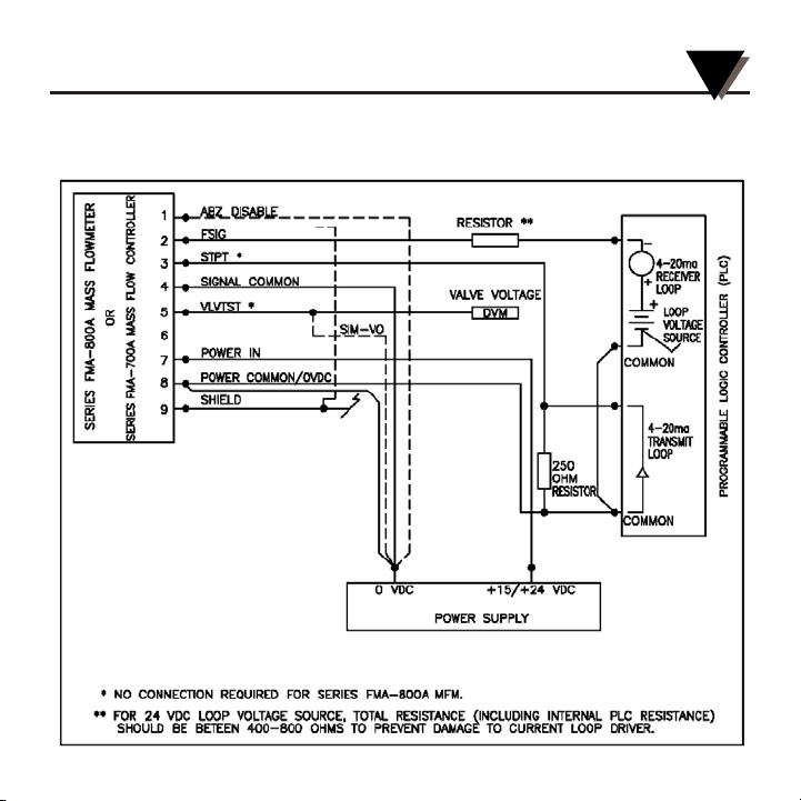
The Series FMA-800A MFM’s and Series FMA-700A MFC’s have available PCB
assemblies which can be configured to provide flow signal output in a 4-20 mAdc current
loop mode. The on-board current driver is not isolated and is electrically referenced to
the power supply common of the MFM/MFC. Figure 8-1 indicates valid and safe flow
signal output load resistance as related to various loop supply voltage sources.
Additionally, the current driver is usable as a current sink and recommended connections
are illustrated in Figure 8-2A. As a protection, in the event of a loop fault, the current
driver limits output current.
Figure 8-1
Flow Signal Output Load Resistance
CURRENT LOOP SPECIFICATIONS
8
Page 34

Figure 8-2A
Recommended
Electrical Connections
for
Sinking Current Driver
With the 9-pin D-connector on the right, locate the row of three (3) low-profile trimpots
directly below (approximately
1
⁄2") the flow trimpots on the PCB assembly. On the left and
directly below the low-profile trimpots, locate (2) blue jumper blocks. To the left of the
jumper blocks is a five (5)-pin connector, the sensor assembly’s connection to the PCB
assembly. Note the orientation of the sensor assembly’s 5-pin connector (pin having red
shrink sleeve on bottom). Disconnect the sensor assembly’s 5-pin connector form the PCB
assembly. To configure the PCB assembly as a sinking current driver, position the jumper
blocks to connect pins 2 & 3 and 5 & 6.
After configuring the PCB assembly appropriately, reconnect the sensor assembly’s 5-pin
connector to the PCB assembly.
When used as a current sink, there may be a separate power supply for the instrument
(V) and for the loop (Vs). With the loop configured to use the current drivers as a current
source, the display load should be referenced to the instrument power supply common.
30
CURRENT LOOP SPECIFICATIONS
8
Page 35

31
Flowmeters and flow controllers are shipped from the factory calibrated for use with a specific gas.The
original calibration conditions are stated on the serial tag attached to the top of the p.c. board cover.
It is desired to use a flowmeter or contoller with a gas other than the original calibration gas, the
following calibration is necessary.
Select the conversion factor for each gas from the chart. Multiply the output reading by the ratio of the
conversion factor for the desired gas to the conversion factor for the calibration gas.
Example: Meter calibration on N
2
(200 cc/min.), Gas flow passing the meter is CO2, Output signal is
80.0% (4V),
Actual CO
2
flow = 80.0 x
0.745
= 59.6% or
59.6
x 200 = 119.2 cc/min.
1.000 100
GAS CONVERSION FACTORS
9
Page 36

GAS CONVERSION FACTORS
9
32
Page 37

33
GAS CONVERSION FACTORS
9
Page 38

GAS CONVERSION FACTORS
9
34
Page 39

35
GAS CONVERSION FACTORS
9
Page 40

NOTES:
Page 41

FOR W
ARRANTY
RETURNS, please have the
following information available BEFORE contacting
OMEGA:
1. Purchase Order number under which the
product was PURCHASED,
2. Model and serial number of the product under
warranty, and
3. Repair instructions and/or specific problems
relative to the product.
FOR NON-WARRANTY REPAIRS,
consult OMEGA
for current repair charges. Have the following
information available BEFORE contacting OMEGA:
1. Purchase Order number to cover the COST
of the repair,
2. Model and serial number of the product, and
3. Repair instructions and/or specific problems
relative to the product.
OMEGA’s policy is to make running changes, not model changes, whenever an improvement is possible. This affords our customers the
latest in technology and engineering.
OMEGA is a registered trademark of OMEGA ENGINEERING, INC.
© Copyright 2005 OMEGA ENGINEERING, INC. All rights reserved. This document may not be copied, photocopied, reproduced, translated, or
reduced to any electronic medium or machine-readable form, in whole or in part, without the prior written consent of OMEGA ENGINEERING, INC.
WARRANTY/ DISCLAIMER
OMEGA ENGINEERING, INC. warrants this unit to be free of defects in materials and workmanship for a period of
13 months from date of purchase. OMEGA’s WARRANTY adds an additional one (1) month grace period to the
normal one (1) year product warranty to cover handling and shipping time. This ensures that OMEGA’s customers
receive maximum coverage on each product.
If the unit malfunctions, it must be returned to the factory for evaluation. OMEGA’s Customer Service Department will issue
an Authorized Return (AR) number immediately upon phone or written request. Upon examination by OMEGA, if the unit is
found to be defective, it will be repaired or replaced at no charge. OMEGA’s WARRANTY does not apply to defects resulting
from any action of the purchaser, including but not limited to mishandling, improper interfacing, operation outside of design
limits, improper repair, or unauthorized modification. This WARRANTY is VOID if the unit shows evidence of having been
tampered with or shows evidence of having been damaged as a result of excessive corrosion; or current, heat, moisture
or vibration; improper specification; misapplication; misuse or other operating conditions outside of OMEGA’s control.
Components in which wear is not warranted, include but are not limited to contact points, fuses, and triacs.
OMEGA is pleased to offer suggestions on the use of its various products. However, OMEGA neither
assumes responsibility for any omissions or errors nor assumes liability for any damages that result
from the use of its products in accordance with information provided by OMEGA, either verbal or
written. OMEGA warrants only that the parts manufactured by the company will be as specified and
free of defects. OMEGA MAKES NO OTHER WARRANTIES OR REPRESENTATIONS OF ANY KIND
WHATSOEVER, EXPRESSED OR IMPLIED, EXCEPT THAT OF TITLE, AND ALL IMPLIED WARRANTIES
INCLUDING ANY WARRANTY OF MERCHANTABILITY AND FITNESS FOR A PARTICULAR PURPOSE
ARE HEREBY DISCLAIMED. LIMITATION OF LIABILITY: The remedies of purchaser set forth herein are
exclusive, and the total liability of OMEGA with respect to this order, whether based on contract,
warranty, negligence, indemnification, strict liability or otherwise, shall not exceed the purchase
price of the component upon which liability is based. In no event shall OMEGA be liable for
consequential, incidental or special damages.
CONDITIONS: Equipment sold by OMEGA is not intended to be used, nor shall it be used: (1) as a “Basic
Component” under 10 CFR 21 (NRC), used in or with any nuclear installation or activity; or (2) in medical
applications or used on humans. Should any Product(s) be used in or with any nuclear installation or activity,
medical application, used on humans, or misused in any way, OMEGA assumes no responsibility as set forth in our
basic WARRANTY/ DISCLAIMER language, and, additionally, purchaser will indemnify OMEGA and hold OMEGA
harmless from any liability or damage whatsoever arising out of the use of the Product(s) in such a manner.
RETURN REQUESTS / INQUIRIES
Direct all warranty and repair requests/inquiries to the OMEGA Customer Service Department. BEFORE RETURNING
ANY PRODUCT(S) TO OMEGA, PURCHASER MUST OBTAIN AN AUTHORIZED RETURN (AR) NUMBER FROM
OMEGA’S CUSTOMER SERVICE DEPARTMENT (IN ORDER TO AVOID PROCESSING DELAYS). The assigned AR
number should then be marked on the outside of the return package and on any correspondence.
The purchaser is responsible for shipping charges, freight, insurance and proper packaging to prevent breakage in transit.
Page 42

M0638/0405
TEMPERATURE
䡺⻬
Thermocouple, RTD & Thermistor
Probes, Connectors, Panels & Assemblies
䡺⻬
Wire: Thermocouple, RTD & Thermistor
䡺⻬
Calibrators & Ice Point References
䡺⻬
Recorders, Controllers & Process Monitors
䡺⻬
Infrared Pyrometers
PRESSURE, STRAIN
AND FORCE
䡺⻬
Transducers & Strain Gages
䡺⻬
Load Cells & Pressure Gages
䡺⻬
Displacement Transducers
䡺⻬
Instrumentation & Accessories
FLOW/LEVEL
䡺⻬
Rotameters, Gas Mass Flowmeters
& Flow Computers
䡺⻬
Air Velocity Indicators
䡺⻬
Turbine/Paddlewheel Systems
䡺⻬
Totalizers & Batch Controllers
pH/CONDUCTIVITY
䡺⻬
pH Electrodes, Testers & Accessories
䡺⻬
Benchtop/Laboratory Meters
䡺⻬
Controllers, Calibrators, Simulators
& Pumps
䡺⻬
Industrial pH & Conductivity Equipment
DATA ACQUISITION
䡺⻬
Data Acquisition &
Engineering Software
䡺⻬
Communications-Based
Acquisition Systems
䡺⻬
Plug-in Cards for Apple, IBM
& Compatibles
䡺⻬
Datalogging Systems
䡺⻬
Recorders, Printers & Plotters
HEATERS
䡺⻬
Heating Cable
䡺⻬
Cartridge & Strip Heaters
䡺⻬
Immersion & Band Heaters
䡺⻬
Flexible Heaters
䡺⻬
Laboratory Heaters
ENVIRONMENTAL
MONITORING AND CONTROL
䡺⻬
Metering & Control Instrumentation
䡺⻬
Refractometers
䡺⻬
Pumps & Tubing
䡺⻬
Air, Soil & Water Monitors
䡺⻬
Industrial Water & Wastewater
Treatment
䡺⻬
pH, Conductivity & Dissolved
Oxygen Instruments
Where Do I Find Everything I Need for
Process Measurement and Control?
OMEGA…Of Course!
Shop online at omega.com
 Loading...