

Page 1

OMEGA
ENGINEERING, INC.
oium
Al
Behmdogks
FMA-5000 SERIES
Electronic Mass
Flowmeters
CompIqy
Operator’s Manual
Page 2
OMEGAwanamsVlisun~~obeheeddetedsinmaterialsandwakmanshl~andtogivesatlsfactoryseMcefapenod
of
13
one (1) year
coverage
Serwce
exammatlon
WARRANTY is VOID if the
Z3~Kl¶UitOlWCS3Sh
orolheroperat~ngconditionsoutsdedOMEGA ’scontrol.Compo~mtswhichwearorwhlcharedamagedbymlsuse
ara
not warranted.
EVERY PRECAUTION FOR ACCURACY HAS BEEN TAKEN IN THE PREPARATION OF THIS MANUAL,
HOWEVER, OMEGA ENGINEERING, INC. NEITHER ASSUMES
ERRORS THAT MAY APPEAR NOR ASSUMES LIABILITY FOR ANY DAMAGES THAT RESULT FROM THE USE
OF THE PRODUCTS IN ACCORDANCE WITH THE INFORMATION CONTAINED IN THE MANUAL.
dale
m~nthsfrcm
on
Daparfrnenl
of purchase. OMEGA Warranty adds an
product
warranty
,wcduct
will issue an
by OMEGA, if the
These
aner
handling and
to
shculd
unl
If the cad
Aulhortzed
Return (AR) number immediately upon phone or
defecliw
lo
is found
evidenrx
cwent.
be
of having
moustum
0r
unl
unil
shows
camsnm;
include contact points, fuses, and
addiiional
tune.
This ensures that shiing
ba
returned to the
musl
1 malfwUii,
repaired
it
will be
been
tampered with or shows
~mpoper
wbralar;
heat.
of
triacs.
RESPONSIBILR-Y
one (1)
or
replaced
specillcatm:
mooth
faclofy
pertod
grace
ourctiomers
for
al
no charge. However.
FOR ANY OMISSIONS OR
to the normal
recant
waluatan.
Our
wrlllen
betng
of
ewdence
mnap+atkm;
maxlmum
Customer
request.
damaged
mws-9
Upon
the
WARRANTY
Teebwk#lrm
O.UEGA
I.
One
Omega Drive.
Stamford.
Connwtiiu~
Call OMEGA
14DD.8246342 I
Sales:
Customer Service:
Engineering Assistance:
359-1660
(203)
CT:
‘In
And International
Direct all warranty and
telephone number (203)
CONTACT
RETURN (AR) NUMBER. The
the
To avold
OMEGA’s policy is to make running changes, not model changes, whenever an improvement is
possible. That way our customers get the latest in technology and engineering.
OMEGA@is
0
Copyright
in this manual may be reproduced in any manner, either wholly or in part for any purpose whatsoever
without written permission from OMEGA ENGINEERING, INC.
TtfE
return
pa&age.
pmcesslng
1. Returnee ’s name,
2. Model and
Rapalr
3.
a registered trademark of OMEGA ENGINEERING, INC.
Cb&my
Box
4047
C690743D47
Tot1
Free’
-BOO-TC0AEGA
1
l-QQQ-Q22-2378
OMEGA CUSTOMER SERVICE DEPARTMENT TO OBTAIN AN AUTHORIZED
d&y&
Serial
Instructions.
1989
OMEGA ENGINEERING, INC. All rights reserved including illustrations. Nothing
I l-800-622.BEST
l-QW-Q72-94361
CABLE: OMEGA
996404
TELEX:
Return
mquests/lnqulrlm~
mpalr
359.1660.
BEFORE RETURNING ANY INSTRUMENT, PLEASE
designated
AR number should then be marked on the
also please be
addmss,
and phone number.
numben.
l-QDMJSA-WHEN
EASYLINK:
FAX: (203)
RaqueWIlnqulrtas
to OMEGA Customer
oure
to Include:
62968934
35Q-77tX
Servkr Department,
outslde
of
Printed in U.S.A
M698/068
Page 3
SECTION 1
1.1
General Description
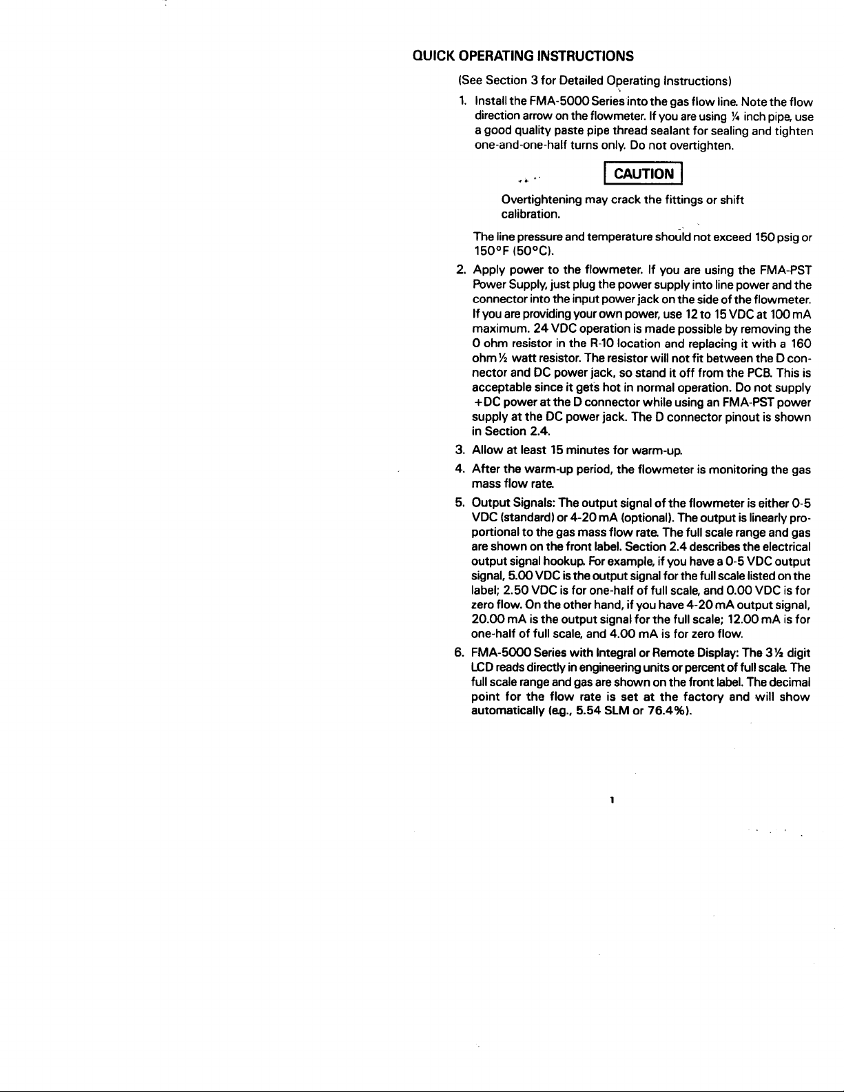
TABLE OF CONTENTS
FMA-5000 Series
INTRODUCTION
.
2
. . . . . . . . . . . . . . . . . .
.
2
. . . . . . . . . . . . . . . . .
SECTION
2.1
2.2
2.3
2.4
2.4.1
2 .4 .2
SECTION 3 OPERATION.
3.1
3.2
3.3
SECTION 4 MAINTENANCE
4.1
4.1.1
4.1.2
4.1.3
SECTION 5
5.1
5.2
5.3
2 INSTALLATION. . . . . . . . . . . . . . . . . . . . . . 2
Unpacking
Mechanical Installation
Transducer Connections
Electrical Connections
g-Pin
OEM Electrical Connections
...........................
...................
..................
...................
“D” Connector Pin Assignments
...............
........
........................
Operating Instructions
Notes to Operating Instructions
Principle of Operation
...........................
.....................
........................... .
.....................
Flow Path Cleaning
Inlet and Outlet Screen
Laminar Flow Element
Sensor Tube
FLOW CALIBRATION
General Calibration Procedure
Recalibration over the Same Flow Range
Flow Calibration Over a Different Flow Range and/or Gas
.............................
..........................
(LFE)
........................
.................................
......................
..................
...............
....
SECTION 6 TROUBLESHOOTING. ................ .
6.1
6.2
General......................................1 6
Troubleshooting Guide
...........................
.
.
.
.
.
,12
.12
.12
.13
.14
.16
2
3
3
4
4
6
7
7
7
9
12
14
14
15
16
SECTION 7 SPECIFICATIONS
APPENDICES
1.
2.
3.
4.
Exploded View of Transducer and Parts List
Electrical Schematics
Conversion of Flow Rate
KFactors
............................... .
............................
....................................
....................
.........................
............
.17
..19
.20
.21
.22
.23
Page 4
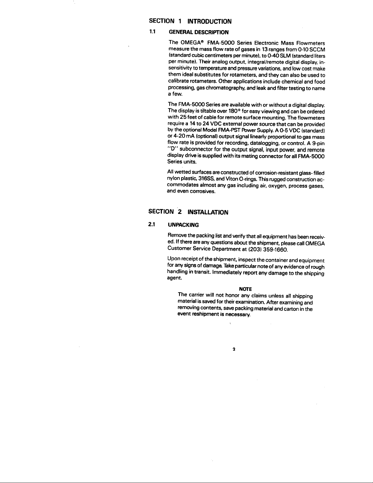
QUICK OPERATING INSTRUCTIONS
Section 3 for Detailed Operating Instructions)
(See
1.
Install the FMA-5000 Series into the gas flow line. Note the flow
direction arrow on the flowmeter. If you are using
a good quality paste pipe thread sealant for sealing and tighten
one-and-one-half turns only. Do not overtighten.
%
inch pipe, use
I&
.’
II
Overtightening may crack the fittings or shift
calibration.
The line pressure and temperature
(5OY).
150°F
2.
Apply power to the flowmeter. If you are using the FMA-PST
should
not exceed 150 psig
or
Power Supply, just plug the power supply into line power and the
connector into the input power jack on the side of the flowmeter.
If you are providing your own power, use 12 to 15 VDC at 100
mA
maximum. 24 VDC operation is made possible by removing the
0 ohm resistor in the R-10 location and replacing it with a 160
%
watt resistor. The resistor will not fit between the D con-
ohm
nector and DC power jack, so stand it off from the PCB. This is
acceptable since it gets hot in normal operation. Do not supply
+DC power at the D connector while using an FMA-PST power
supply at the DC power jack. The D connector
pinout
is shown
in Section 2.4.
3.
Allow at least 15 minutes for warm-up
4.
After the warm-up period, the flowmeter is monitoring the gas
mass flow rate
5.
Output Signals: The output signal of the flowmeter is either O-5
mA
VDC (standard) or 4-20
(optional). The output is linearly pro-
portional to the gas mass flow rate. The full scale range and gas
are shown on the front label. Section 2.4 describes the electrical
output signal hookup For example, if you have a O-5 VDC output
signal, 5.00 VDC is the output signal for the full scale listed on the
label; 2.50 VDC is for one-half of full scale, and 0.00 VDC is for
mA
zero flow. On the other hand, if you have 4-20
mA
20.00
one-half of full scale, and 4.00
6.
FMA-5000 Series with Integral or Remote Display: The
is the output signal for the full scale; 12.00
mA
is for zero flow.
output signal,
mA
is for
3% digit
LCD reads directly in engineering units or percent of full scale The
full scale range and gas are shown on the front label. The decimal
point for the flow rate is set at the factory and will show
automatically (e.g., 5.54
SLM
or
76.4%).
Page 5
SECTION 1 INTRODUCTION
1.1
GENERAL DESCRIPTION
The OMEGA@ FMA-5000 Series Electronic Mass Flowmeters
measure the mass flow rate of gases in 13 ranges
(standard cubic centimeters per minute), to 040 SLM (standard liters
per minute). Their analog output, integral/remote digital display, in-
sensitivity to temperature and pressure variations, and low cost make
them ideal substitutes for rotameters, and they can also be used to
calibrate rotameters. Other applications include chemical and food
processing, gas chromatography, and leak and filter testing to name
a few.
The FMA-5000 Series are available with or without a digital display.
tiltable
The display is
with 25 feet of cable for remote surface mounting. The flowmeters
require a 14 to 24 VDC external power source that can be provided
by the optional Model FMA-PST Power Supply. A O-5 VDC (standard)
or 4-20
flow rate is provided for recording, datalogging, or control. A
“D” subconnector for the output signal, input power, and remote
display drive is supplied with its mating connector for all FMA-5000
Series units.
All wetted surfaces are constructed of corrosion-resistant glass- filled
nylon plastic,
commodates almost any gas including air, oxygen, process gases,
and even corrosives.
(optional) output signal linearly proportional to gas mass
mA
over
316SS.
and Viton O-rings. This rugged construction ac-
fromO-10
180° for easy viewing and can be ordered
SCCM
g-pin
SECTION 2 INSTALLATION
2.1
UNPACKING
Remove the packing list and verify that all equipment has been receiv-
ed. If there are any questions about the shipment, please call OMEGA
Customer Service Department at (203) 359-1660.
Upon receipt of the shipment, inspect the container and equipment
for any signs of damage Take particular note of any evidence of rough
handling in transit. Immediately report any damage to the shipping
agent.
The carrier will not honor any claims unless all shipping
material is saved for their examination. After examining and
removing contents, save packing material and carton in the
event reshipment is necessary.
NOTE
2
Page 6
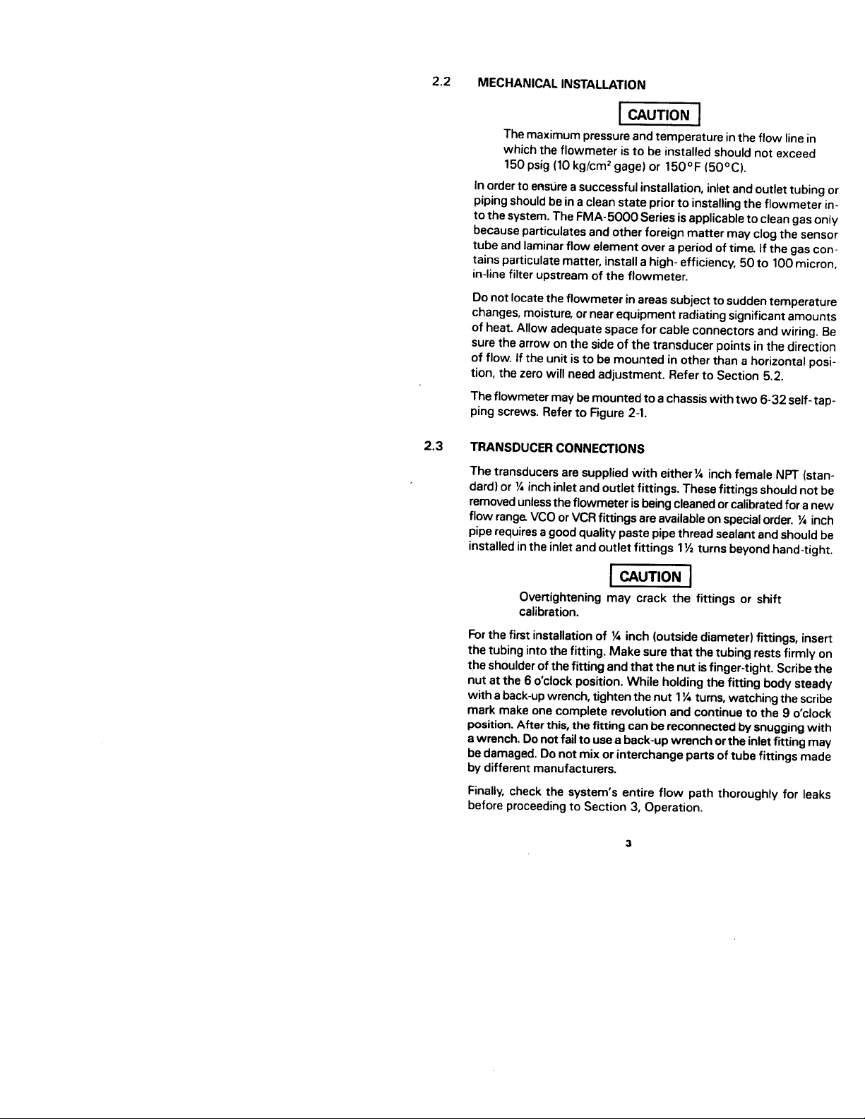
2.2
MECHANICAL INSTALLATION
-1
The maximum pressure and temperature
in
the flow line in
which the flowmeter is to be installed should not exceed
(5OOC).
150 psig
In order to
kg/cm2
gage) or
(10
enstire
a successful installation, inlet and outlet tubing or
150°F
piping should be in a clean state prior to installing the flowmeter in-
to the system. The FMA-5000 Series is applicable to clean gas only
because
particulates
tube and laminar flow element over a period of time.
and other foreign matter may clog the sensor
If the gas con-
tains particulate matter, install a high- efficiency, 50 to 100 micron,
in-line filter upstream of the flowmeter.
Do not locate the flowmeter in areas subject to sudden temperature
changes, moisture, or near equipment radiating significant amounts
of heat. Allow adequate space for cable connectors and wiring. Be
sure the arrow on the side of the transducer points in the direction
of flow. If the unit is to be mounted in other than a horizontal posi-
tion, the zero will need adjustment. Refer to Section 5.2.
The flowmeter may be mounted to a chassis with two 6-32 self- tap-
ping screws. Refer to Figure 2-l.
2.3
TRANSDUCER CONNECTIONS
The transducers are supplied with either% inch female NPT (stan-
dard) or
%
inch inlet and outlet fittings. These fittings should not be
removed unless the flowmeter is being cleaned or calibrated for a new
%
flow range VCO or VCR fittings are available on special order.
inch
pipe requires a good quality paste pipe thread sealant and should be
installed in the inlet and outlet fittings 1% turns beyond hand-tight.
Ovettightening may crack the fittings or shift
calibration.
%
For the first installation of
inch (outside diameter) fittings, insert
the tubing into the fitting. Make sure that the tubing rests firmly on
the shoulder of the fitting and that the nut is finger-tight. Scribe the
nut at the 6 o ’clock position. While holding the fitting body steady
the
with a back-up wrench, tighten
nut 1% turns, watching the scribe
mark make one complete revolution and continue to the 9 o ’clock
position. After this, the fitting can be reconnected by snugging with
a wrench. Do not fail to use a back-up wrench or the inlet fitting may
be damaged. Do not mix or interchange parts of tube fittings made
by different manufacturers.
Finally, check the system’s entire flow path thoroughly for leaks
before proceeding to Section 3, Operation.
Page 7
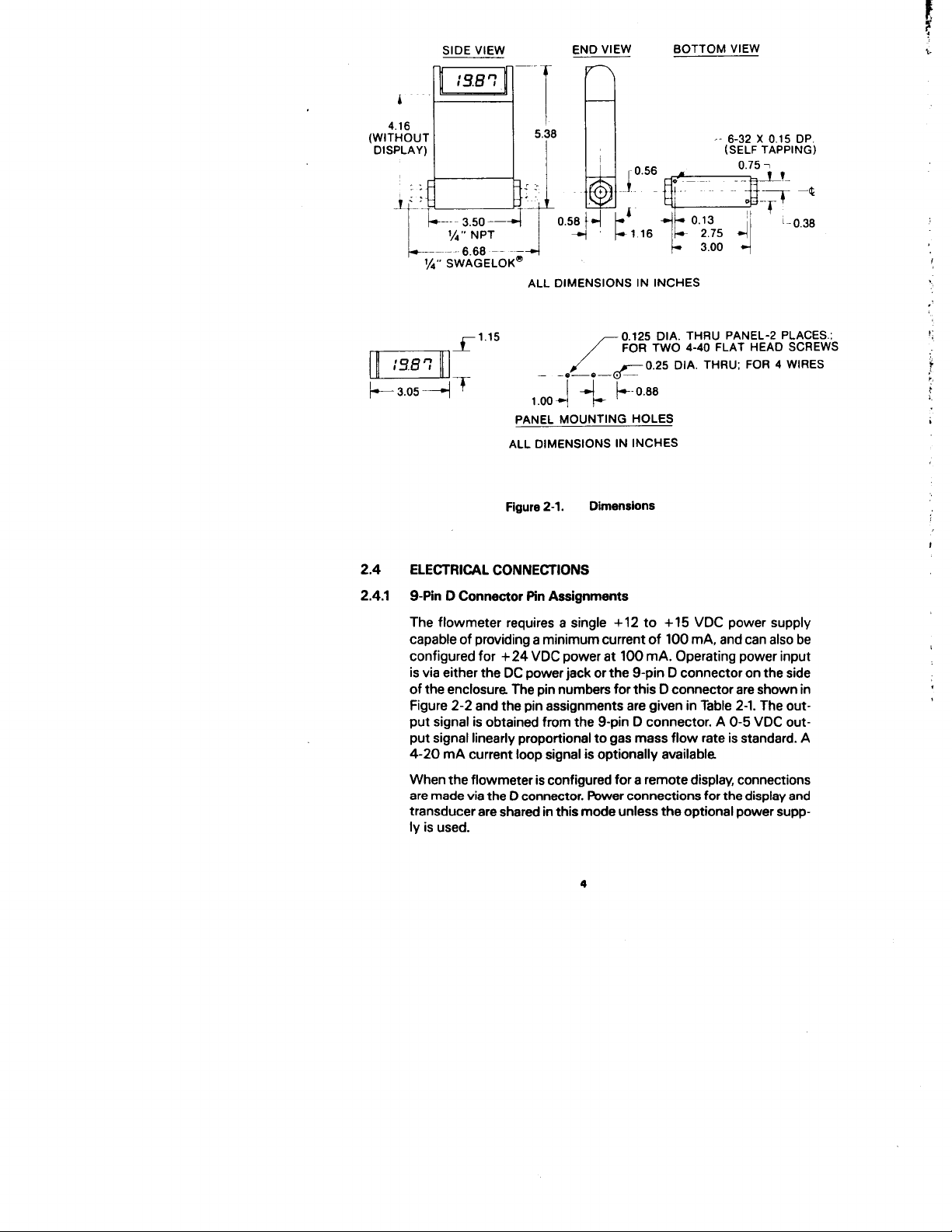
4.16
(WITHOUT
DISPLAY)
SIDE VIEW
-.
6.66
__
END VIEW
~-
~-
ALL
DIMENSIONS IN INCHES
0.125 DIA. THRU PANEL-2 PLACES.:
PANEL MOUNTING HOLES
ALL DIMENSIONS IN INCHES
BOTTOM VIEW
‘-
6-32 X 0.15 DP.
(SELF TAPPING)
2.4
2.4.1
2-l.
Dimensions
Figure
ELECTRICAL CONNECTIONS
g-Pin
D Connector Pin Assignments
+15 VDC power supply
The flowmeter requires a single
capable of providing a minimum current of 100
configured for
+24
VDC power at 100
is via either the DC power jack or the
+12 to
mA,
and can also be
mA.
Operating power input
g-pin
D connector on the side
of the enclosure. The pin numbers for this D connector are shown in
Figure 2-2 and the pin assignments are given in Table 2-1. The out-
g-pin
put signal is obtained from the
D connector. A O-5 VDC out-
put signal linearly proportional to gas mass flow rate is standard. A
mA
4-20
current loop signal is optionally available.
When the flowmeter is configured for a remote display, connections
are made
D connector. Power connections for the display and
via the
transducer are shared in this mode unless the optional power supp-
ly is used.
4
Page 8
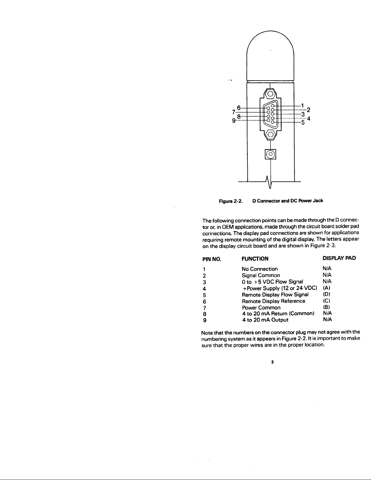
Figure 2-2. D Connector and DC Power Jack
The following connection points can be made through the D connec-
tor or, in OEM applications, made through the circuit board solder pad
connections. The display pad connections are shown for applications
requiring remote mounting of the digital display. The letters appear
on the display circuit board and are shown in Figure 2-3.
PIN NO.
1
2 Signal Common
3
4
5
6
7 Power Common
8
9 4 to 20
FUNCTION DISPLAY PAD
No Connection
N/A
N/A
+
5 VDC Flow Signal
0 to
Supply (12 or 24
VDCl+Power
Remote Display Flow Signal
Remote Display Reference
N/A
(A)
0)
(Cl
(B)
4 to 20
mA
Return (Common)
mA Output
N/A
N/A
Note that the numbers on the connector plug may not agree with the
numbering system as it appears in Figure 2-2. It is important to make
sure that the proper wires are in the proper location.
Page 9

NOTES
g-pin
Remote display connects through the
D connector
only. The pads A-D in the top right of the main circuit
board are for integral display mounting only.
Power supply voltage must be specified at time
Operating a 12
VDC meter at 24 VDC will cause damage.
of
order.
Running a 24 VDC meter at 12 VDC will result in faulty
operation.
Do not supply +DC power at the D connector while
using an FMA-PST power supply at the DC power jack.
Both supplies may be damaged.
,
‘ FO R
DIGITAL
DISPLAY
“D”
CONNECTOR
Sdder Pad Assignments
Figure 2-3.
2.4.2
OEM Electrical Connections
-
PCB
FOR
Input/Output
One special design OEM version transducer has an electrical port
(hole) on its side for electrical input/outputs. This port is just above the
input power jack (see the exploded view, item 27, in Appendix 11.
Wires entering via this port are soldered to the printed circuit board
as shown in Figure 2-3. The solder pad assignments are given in Table
2-l.
PC6
To gain access to the
to make the solder connections for special
design applications, refer to the exploded view in Appendix 1 and
follow these steps.
6
Page 10
1.
If the flo wme ter has the digital display:
fro m
F irst, re m ove the
(al
rotating the display
tinue to rotate until this lever-ar m action snaps out the two
yokes holding the display (No. 30). Use extra caution during
this operation as excessive force will break the delicate wire
connections. Carefully m ove the display asse m bly to expose
the
ert excessive force on the display while rotating, as doing so
could crack the LCD display.
Next, re m ove the two screws
(b)
351
enclosure (No.
The top, front and back sides of the enclosure can now be
(cl
re m oved
to the flo w pa th), exposing the PCB.
2. If the flo wme ter does not have the digital display:
(al
Remove the label (No.
expose the two screws.
(b)
Then follow steps lb and
To reasse mb le, reverse this process.
For applications requiring flow totalization or alar m s, it is possible to
connect the F MA -5000 Series to the O MEGA FMA -DV Series elec-
tronics. Contact O MEGA Sa les Depart m ent for special applications.
Zrews
two
and the two screws (also No.
(the
display
until.it
securing the display base
10).
front slides out towards you and perpendicular
291
t he transducer by carefully
hits the top plate and slowly con-
35).
Do not ex-
(No.
21)
in the display base (No.(Na
21)
i n the back o f t he
fro m the plain top cover (No. 281 to
lc above.
SECT ION 3 OPERAT ION
3.1
3.2
QU ICK OPERAT ING INSTRUCT IONS
Qu ick operating instructions are given on the first page of this
m anual.
OPERAT ING NOTES
1. Referencing the Flow Rate to Other Te m perature and Pressure
Conditions
The gas flow rate output of the flow m eter is referenced to standard
(7 OOF )
cond iti ons of
unless you have specified otherwise in your order. Be sure you know
the reference conditions of your unit, because it m ay m ake a dif-
ference if you are co mpa ri ng the ou tpu t w it h ano ther type of
flo wme ter. For exa m ple, the output reading of the F MA -5000 Series
w ill be approxi m ately 7 % lo wer if it is referenced to
‘X. Appendix 3 shows how to convert the flow rate output of your
21
instru m ent to other standard conditions and how to find the flow rate
referenced to the actual te m perature and pressure conditions in the
pipe.
21°C
and 760 mm o f m ercury
7
at mospherel.
(1
O°C
rather than
Page 11

2. Accuracy
The standard accuracy is
*2%
of full scale. A
51% accuracy is
available with special calibration or upon recalibration (See Section
5.2). The
signal is accurate to within
curate to within
signal for zero flow can be as much as
note if
rt2% of full scale accuracy means the O-5 VDC output
mA
kO.1
VDC, and the 4-20
mA.
kO.4
you
get an output signal at zero flow (as long as it is within
This means, for example, that the output
kO.1
VDC or
output is ac-
*0.4mA.
Please
either of these two ranges), it does not mean the flowmeter is
malfunctioning. For models with the digital readout, the accuracy is
simply 2% times the full scale flow rate listed on the front label. For
example, if your full scale is 10 SLM, the digital readout will be ac-
curate to
as
kO.2 SLM, and the reading at zero flow may be as much
-+0.2
SLM and still be within the stated accuracy specification.
3. Overranging
If the flow rate exceeds the full scale range listed on the front label,
the output signal and digital display (if you have it) will read a higher
value.
The FMA-5000 Series has not been calibrated for overranged flows
and probably will be both non-linear and inaccurate. If the supply
voltage is only 12 VDC, the overranged reading may only exceed the
full scale reading by 10% maximum. If the supply voltage is higher,
such as with the 24 VDC option, then the output can exceed full
scale by as much as
50%, or more. If you have the digital display, the
display cannot exceed the four digits 1999. If the flow rate exceeds
1999, the right-most digits will blank and only the left-hand “1” will
appear on the display.
Due to the operating principle of the sensor, if the flow overranges,
the output will become nonlinear and at some point will go “over the
hump”. After this point, the output signal will decrease even though
the flow is increasing. This will not cause any damage and will cor-
rect itself, usually within 30 seconds after the flow is shut off or
returns to within the calibrated range of the meter. In systems where
it is possible for overrange conditions to occur, it is recommended that
a valve or critical orifice be inserted in the line to limit the flow to ap-
proximately 25% above the full scale range.
mA
4. Optional 4-20
mA
The 4-20
output signal current flows from the 4-20
pin on the D connector through the load
Output Signal
mA
output
(50 to 500 ohms) to ground.
Figures 3-l and 3-2 illustrate single and multiple installations with cur-
rent loop outputs.
Page 12

5. Zero and Span Adjustments
The zero and span potentiometers are accessed through marked
+2%
ports
on the right side. If your zero output is more than
scale,
you
may adjust the zero potentiometer when you are absolute-
of full
ly certain that you have zero flow.
Since the output does not indicate negative numbers, it is necessary
tD
adjust down from a slightly positive reading. Slowly rotate the zero
clockwise ’uhtil
pot
a positive reading is indicated. Then turn the pot
counterclockwise slowly just until zero is reached. This completes
the zero adjustment.
Normally,
sp’an
adjustments are not made unless you are calibrating
the flowmeter, as described in Section 5. The span adjustment
should not be used unless you have a known precise non-zero flow
rate that you wish to match.
6. Attitude
Unless specified otherwise, the instrument has been calibrated for
(il5’)
installation with the flow direction in the horizontal plane
with
the enclosure facing upward. If your actual installation orientation is
different, you will have to make a small zero adjustment.
PRINCIPLE OF OPERATION
Gas enters the flow body and divides into two flow paths. Most of
the flow goes through the laminar flow bypass. This creates a
pressure drop that forces a small fraction of the flow through the sen-
sor tube.
The straight sensor tube is mounted on the top of the bypass flow
path. Since both paths are perfectly laminar, the ratio of the total flow
(m)
to the sensed flow (ml) is exactly constant. This contributes to
the flowmeter ’s exceptional accuracy. Two resistance detector
(RTD)
coils around the sensor tube direct a constant amount of heat into
the gas stream.
In actual operation, the gas mass flow carries heat from the upstream
coil to the downstream coil. The resulting temperature difference
T2-Tl
is detected by the RTD coils and gives the output signal. Since
the molecules of gas carry away the heat, the output signal is directly
and linearly proportional to gas mass flow.
The laminar flow bypass makes changing of flow ranges easy with
the proper calibration facilities. Each of the two bypasses in the op-
tional Laminar Flow Bypass Set has a combination of rectangular
slots along its circumference as shown in Figure 3-5 below.
To change the flow rate of the flowmeter, follow the instructions pro-
vided with the Laminar Flow Bypass Set and cut away the gates
leading to the right combination of laminar flow paths in one of the
two bypasses. This procedure requires calibration facilities and
minimal skills in electronics.
9
Page 13

4-20mA
SIGNAL
4-20mA
POWER
SUPPLY
+15v
COM
Ffgure
Figure 3-1.
3-2.
Single Unit 4-20 Hookup
.--
Multiple Installation 4-20 Hookup
10
Page 14

STAAIGHTym
SEN53R
#
LAMINAR FLOW BYPASS
i_L ’
TUBE
Figure 3-3.
SENSOR TUBE
3-4.
Figure
F;;--“GATES”
SECT. A-A
Two Flow paths
‘-ANT HEAT, H
rineasc,
-
RTD COILS
r.#
A
--
A
Figure 3-5.
Laminar
Flow Bypass Set
Page 15

SECTION 4 MAINTENANCE
The FMA-5000 Series essentially requires no maintenance and has
no regular maintenance schedule, other than periodic flow path
cleaning if the gas is dirty. Calibrations may be scheduled once or
twice yearly, depending on the accuracy to be maintained, or as
needed.
4.1
4.1.1
4.1.2
Flow Path Cleaning
The flow path (wetted parts)
(sensor tube1 and Viton O-rings (standard).
If you wish to clean the flowmeter, purge it thoroughly
before disconnecting from the gas line when toxic or cor-
rosive gases are used. Never return the instrument to
OMEGA for repair or calibration without fully neutralizing
any toxic gases trapped inside.
Refer to the exploded drawing of the transducer in Appendix 1 when
performing the following procedures. All cleaning of the flow path
can be accomplished with Freon, alcohol or any cleaner safe for the
listed materials.
Inlet and Outlet Screen
Remove inlet and outlet fittings
12)
and either replace or clean the inlet and outlet screens (No.
(No.
14).
Flow
Laminar
Remove the inlet and outlet fitting as in Section 4.1.1. The LFE has a
slightly tapered shape with the larger diameter upstream (on the in-
let side). To remove the LFE for cleaning, push it out the inlet side from
the outlet side using a blunt object which does not mar the flow chan-
nels. A
to carefully clean all active flow channels in the LFE. When reinstalling
the LFE, it is of utmost importance to press it in the correct distance.
Refer to Figure 4-1.
Element
3/s”
nut driver is perfect for this job. When cleaning, be sure
(LFE)
5% glass-filled Nylon
ale
(Na 13). pull out the LFE hold-downs
6/6;
316 SS
12
Page 16

Figure 4-l.
4.1.3 Sensor Tube
LFE Location Within the Flow Body
Opening
Do not remove the PCB bracket (No.
the
sensor cavity
will shift calibration.
7)
unless it is absolutely
necessary to gain access to the sensor cavity. Doing so will shift the
calibration more than 2%. The remaining parts of the flow path are
disassembled as shown in the exploded view in Appendix 1. Note the
position of the insulation blanket before removal and reinstall in the
same manner. After removal, the sensor tube (No.
ed by purging, washing with a solvent, or by
51
rodding
can be clean-
out the 0.031
inch I.D. tube with a 0.029-0.030 inch O.D. rod or wire. To maximize
the time response, the sensor tube has thin walls. Therefore, when
cleaning, be extremely careful not to bend the sensor tube or to mar
its inlet or outlet edges. It is important when reinstalling the sensor
to make sure that no torque is imparted on the sensor tube. Torque
can be eliminated by using a good quality oxygen compatible grease
on the sensor sealing O-rings. The sensor assembly should slide free-
totwist
ly into the cavity flanges without having
it. Twisting will im-
part undesirable torque on the sensor and could lead to long term shif-
ting of the zero value Also, take care to not disturb or unravel the sen-
sor windings.
13
Page 17

SECTION 5 CALIBRATION
5.1
5.2
GENERAL FLOW CALIBRATION PROCEDURE
Flow calibration requires a calibration standard of at least double ac-
curacy and preferably an order of magnitude better. Most calibrations
can be done using dry nitrogen and the
“K” factors and gas tables
given in Appendix 4.
RECALIBRATION OVER THE SAME FLOW RANGE
Flow recalibration is performed by using the following procedure.
Refer to the electrical schematics in Appendix 2. Calibration checks
and minor adjustments to the zero and full scale may be made via the
access ports in the side of the enclosure. If the linearity needs adjust-
ment (as may be required when installing a different laminar flow ele-
ment bypass to.change the range), go to Step 4.
Step 1
Warm-Up: Plug in the flowmeter to be calibrated and allow
at least 15 minutes warm-up time before attempting any
adjustments.
Step 2
Zero Adjust: Slide open the zero and span access ports on
the side. Using a voltmeter connected to the meter output
Step 3
pins, adjust the zero potentiometer
for 4-20
outputs).
mA
(R5)
for zero flow
Check Full Scale: Generate the full scale flow using a meter-
mA
(4
ing valve in line with the instrument under test. Compare the
indicated flow rate with the flow standard reading. If they
agree to within
ilO%,
adjust the span potentiometer
(R21)
for exact agreement. If the readings do not agree within
*lo%,
attempt to determine the cause of disagreement.
Possibilities are:
Partially clogged or dirty sensor tube
al
Wrong or improper use of K factor
b)
Wrong or improper correction for temperature and
Cl
pressure
Leaks in the system or in the flowmeter
d)
Replacement of parts in the flow path do not exactly
e)
match the original parts.
gD
to
This completes the calibration procedure To adjust linearity,
Step
4.
Step 4
Adjusting Linearity: First gain access to the printed circuit
board inside the enclosure by using the procedure describ-
ed in Section 2.4.3. Orient the meter so that the component
plug
side of the circuit board is facing you.
allow it to
warm up for at least 15 minutes.
in the meter and
14
Page 18

Page 19

Page 20

Page 21

Page 22

Page 23

Page 24

Page 25

Page 26

Page 27

Page 28

Page 29

Page 30

Page 31

Page 32

Page 33

Page 34

Page 35

Page 36

 Loading...