

Page 1
DPF6000/DPF5000
Input Options
User’s Guide
Shop on line at
www.omega.com
e-mail: info@omega.com
™
®
Page 2

It is the policy of OMEGA to comply with all worldwide safety and EMC/EMI regulations that apply. OMEGA is constantly pursuing certification of its products to the European New
Approach Directives. OMEGA will add the CE mark to every appropriate device upon certification.
The information contained in this document is believed to be correct, but OMEGA Engineering, Inc. accepts no liability for any errors it contains, and reserves the right to alter
specifications without notice.
WARNING: These products are not designed for use in, and should not be used for, patient-connected applications.
This device is marked with the international caution symbol. It is important to read the Setup Guide before installing or commissioning this device as the guide contains important
information relating to safety and EMC.
This device is marked with the international caution symbol. It is important to read the Setup Guide before installing or commissioning this device as the guide contains
important information relating to safety and EMC.
!
®
®
OMEGAnet® On-Line Service
www.omega.com
Internet e-mail
info@omega.com
Servicing North America:
USA: One Omega Drive, P.O. Box 4047
ISO 9001 Certified Stamford CT 06907-0047
TEL: (203) 359-1660 FAX: (203) 359-7700
e-mail: info@omega.com
Canada: 976 Bergar
Laval (Quebec) H7L 5A1
TEL: (514) 856-6928 FAX: (514) 856-6886
e-mail: info@omega.ca
For immediate technical or application assistance:
USA and Canada: Sales Service: 1-800-826-6342 / 1-800-TC-OMEGA
Customer Service: 1-800-622-2378 / 1-800-622-BEST
Engineering Service: 1-800-872-9436 / 1-800-USA-WHEN
Mexico and TEL: (001)800-TC-OMEGA® FAX: (001) 203-359-7807
Latin America: En Español: (001) 203-359-7803
e-mail: espanol@omega.com
®
®
®
Servicing Europe:
Benelux: Postbus 8034, 1180 LA Amstelveen, The Netherlands
TEL: +31 20 3472121 FAX: +31 20 6434643
Toll Free in Benelux: 0800 0993344
e-mail: sales@omegaeng.nl
Czech Republic: Frystatska 184, 733 01 Karviná
TEL: +420 59 6311899 FAX: +420 59 6311114
e-mail: info@omegashop.cz
France: 11, rue Jacques Cartier, 78280 Guyancourt
TEL: +33 1 61 37 29 00 FAX: +33 1 30 57 54 27
Toll Free in France: 0800 466 342
e-mail: sales@omega.fr
Germany/Austria: Daimlerstrasse 26, D-75392 Deckenpfronn, Germany
TEL: +49 7056 9398-0 FAX: +49 7056 9398-29
Toll Free in Germany: 0800 639 7678
e-mail: info@omega.de
United Kingdom: One Omega Drive
ISO 9002 Certified River Bend Technology Centre
Northbank, Irlam Manchester M44 5BD United Kingdom
TEL: +44 161 777 6611 FAX: +44 161 777 6622
Toll Free in England: 0800 488 488
e-mail: sales@omega.co.uk
Page 3

i
TABLE OF CONTENTS
The Input Options Manual is divided into three major sections. Each option board
contains circuitry which is exclusive of the others. The main board assembly diagram
is identical for all of the input options, however, and should be referred to when jumper
configuring each option board. This illustration is located in Section 1.10 Drawings.
ISOLATED SIGNAL CONDITIONER OPTION
PAGE
1.1 General ................................................................................................................1
1.2 Mechanical Installation ........................................................................................2
1.3 Electrical Connections ........................................................................................3
1.4 Inputs and Outputs ..............................................................................................5
1.5 Trigger Level Adjustment ....................................................................................7
1.6 Hysteresis Selection ............................................................................................8
1.7 Debouncing Monostable Circuit ..........................................................................8
1.8 Configuration ......................................................................................................9
1.9 Specifications ....................................................................................................10
1.10 Drawings ............................................................................................................11
NON-ISOLATED SIGNAL CONDITIONER OPTION
2.1 General ..............................................................................................................13
2.2 Mechanical Installation ......................................................................................13
2.3 Electrical Connections ......................................................................................14
2.4 Inputs and Outputs ............................................................................................16
2.5 Configuration ....................................................................................................17
2.6 Specifications ....................................................................................................17
2.7 Drawings............................................................................................................18
ANALOG INPUT OPTION
3.1 General ..............................................................................................................19
3.2 Mechanical Installation ......................................................................................20
3.3 Electrical Connection and Configuration ..........................................................21
3.4 Low-Frequency Cutoff ......................................................................................24
3.5 Open Circuit Indication ......................................................................................24
3.6 Power ................................................................................................................24
3.7 Calibration..........................................................................................................25
3.8 Specifications ....................................................................................................25
Page 4

ii
ILLUSTRATIONS PAGE
Figure 1-1 Exploded View ....................................................................................................2
Figure 1-2 Simplified Block Diagram of the Signal Conditioner ............................................6
Figure 1-3 P6A1A Potentiometer/Jumper Locations ............................................................7
Figure 1-4 Debouncing a Mechanical Switch........................................................................8
Figure 1-5 Isolated Signal Conditioner Assembly Diagram ................................................11
Figure 1-8 Main Board Assembly Diagram ........................................................................12
Table 1-1 Wiring and Adjustments for Signal Sources ........................................................4
Table 1-2 Correlation of Sensitivity to Frequency Response ..............................................5
Table 1-3 P6A1A Potentiometer Selection ..........................................................................7
Table 1-4 Jumper Configuration ..........................................................................................9
Figure 2-1 Exploded View ..................................................................................................13
Figure 2-2 Rear View ..........................................................................................................14
Figure 2-3 Non-Isolated Signal Conditioner Assembly Diagram ........................................18
Table 2-1 Required Wiring for Most Commonly Used Sensors ........................................15
Table 2-2 Jumper Configuration ........................................................................................17
Figure 3-1 Exploded View ..................................................................................................20
Figure 3-2 P6A5B Potentiometer/Jumper Locations ..........................................................22
Table 3-1 P6A5A Potentiometer Selection ........................................................................22
Table 3-2 Jumper Positions & Input Wiring For Different Ranges ....................................23
Table 3-3 Cutoff Frequency Selection ..............................................................................24
Table 3-4 Analog Input Signal Range Specifications ........................................................25
Page 5

1
SECTION ONE
ISOLATED SIGNAL CONDITIONER OPTIONS
1.1 GENERAL
The isolated signal conditioner options provide one or two low level, isolated amplifier
channels. Each channel offers:
Adjustable trigger level by a multiturn potentiometer
Three levels of hysteresis, selectable by push-on jumpers
A one-shot (monostable multivibrator) with selectable time for debouncing purposes
Selectable RC filters for contact closure or low frequency applications
High sensitivity (±10 mV) and high protection level (260 V rms) inputs
The above features and the 12.4 V at 20 mA excitation output make this signal conditioner
compatible with a wide range of signal sources such as: contact closure, NPN or PNP opencollector outputs, passive inductive pickups, and most active sensors including NAMUR
standard types.
Page 6
2
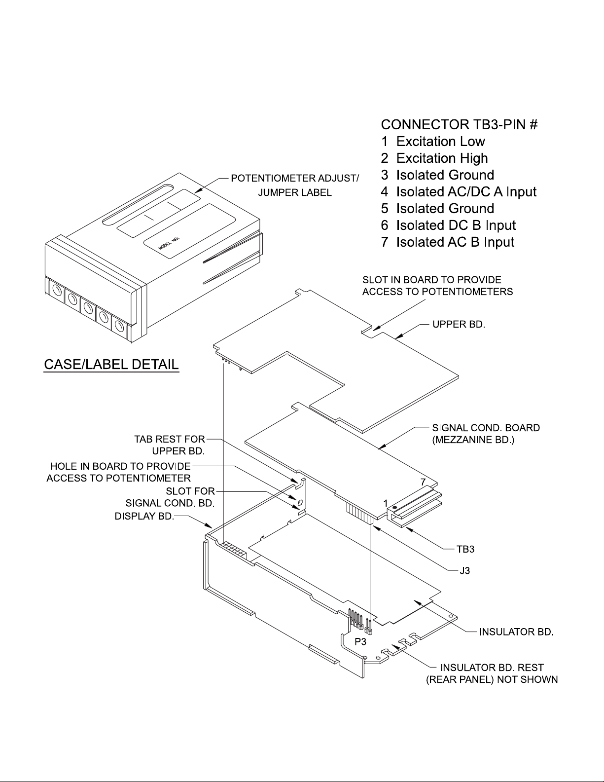
1.2 MECHANICAL INSTALLATION
The signal conditioner board is positioned as a mezzanine, supported by the rear
panel and a slot on the display board (Figure 1-1).
Figure 1-1 Exploded View with Power & Signal Connector
Page 7

3
TO INSTALL:
IMPORTANT: Turn-off the power and input signals from the unit before proceeding.
Failure to do so may result in injury!
CAUTION: The meter has no power-on switch; it will be in operation as soon as you
apply power. To change the factory preset jumpers, disconnect the power from the
unit. Failure to do so may result in injury! The jumpers must be changed by specially
trained personnel.
1. When using a signal conditioning board with the meter, the main board must
be jumper configured prior to installation. For single channel, install SA-I; for dual
channel, install SA-I and SB-I (main board). Refer to Section 1.8 for jumper selection
of input and output features.
2. The insulator board rests atop the lower rear panel, with the two tabs fitting into holes
on the display board.
3. Insert the tab of the signal conditioning board into the slot provided on the display
board.
4. Position J3, an 8-pin connector on the circuit side of the signal conditioner, to mate
with the P3 pins on the main board. Press the board downward until the rear
connectors rest on the lower rear panel.
5. Install the upper rear panel.
1.3 ELECTRICAL CONNECTIONS
Channels A and B of the signal conditioner work separately. The inputs are available on
connector TB3 and are electrically isolated from the counter. The outputs are connected to
the main board with connector J3.
Page 8

4
TYPE REQUIREMENTS WIRING ADJUSTMENTS
1 Passive Inductive Voltage <260 V rms Connect signal wires to Select the hysteresis &
Pickup Voltage >±10 mV TB3-pins 3 & 4. Remove adjust the trigger level
S1, S2, S3, S5, S6, S7. for lowest input voltage
S16 on DC position. (lowest frequency).
2 Active Transducer Operating Voltage = 12.4 V Connect the positive and Select 700 mV hysteresis
(inductive, OPTIC or Operating Current < 20 mA negative supply inputs of (Install S4-A & S8-A).
capacitive) with NPN transducer to the EXC Adjust the multiturn pot
open-collector output. HI & EXC LO, for 0 V trigger level.
respectively. Install S2-A,
S3-A, S6-A, S7-A and
S16-DC.
3 Same as #2, but PNP Same as #2 Same as #2, except Same as #2
open-collector output. install S2-A & S6-A,
remove S3-A & S7-A.
4 TTL- or CMOS- ---- Connect signal output to Select 700 mV hysteresis
compatible signal TB3- pin 4 and Ground to and adjust the trigger
TB3- pin 3. Remove level for 1 V.
jumpers from S2, S3, S6
and S7.
5 Contact Closure Off duration > 100 ms Connect the two ends of Do the #4 adjustments.
(slow) (less than 5 on/off per sec) the contact to TB3-pins 2 Install S1-A and S5-A.
and 4. Install S16-DC. Select the debounce time
Remove S2, S3, S6, S7. if required.
6 Contact Closure Off duration < 100 ms Same as #5 except install Same as #5
(fast) S2-A & S6-A.
7 NAMUR type sensors NAMUR standard Connect the positive Same as #2
(2-wire) sensor input to TB3-pin 4
and the negative sensor
input to TB3-pin 1. Install
S2-A, S3-A, S6-A, S7-A
and S16-DC.
Table 1-1 Wiring and Adjustments for Signal Sources
Page 9

5
1.4 INPUTS AND OUTPUTS
INPUTS
Signal conditioning inputs and excitation outputs are available on TB3, a 7-position header
(shown in Figure 1-1).
Refer to the block diagram in Figure 1-2. Channel A input is available on connector TB3–pin 4.
Pins 6 and 7 are allocated to DC and AC inputs on Channel B. Pins 3 and 5 are isolated
ground (signal return).
TB3 mates with two screw-clamp connectors: a 4-position, TB3J4, and a 3-position, TB3J3.
The 4-position connector may be used with a single or dual-channel signal conditioner; the
3-position may be used only with a dual-channel signal conditioner.
The trigger level can be adjusted between -2 and +2 volts. When the input signal has a large
DC level and does not cross the trigger level range, the AC input should be used. The AC
input is coupled to the DC input with a 0.1 uF capacitor. The maximum non-destructive DC
blocking voltage of this input is 250 V. This input should be left open when not used.
Sensitivity for a Square Frequency Response
Wave Input DC Input AC Input
±10 mV DC - 1 kHz 5 Hz - 1 kHz
±25 mV DC - 20 kHz 2 Hz - 20 kHz
±50 mV DC - 100 kHz 2 Hz - 100 kHz
Table 1-2 Correlation of Sensitivity to Frequency Response
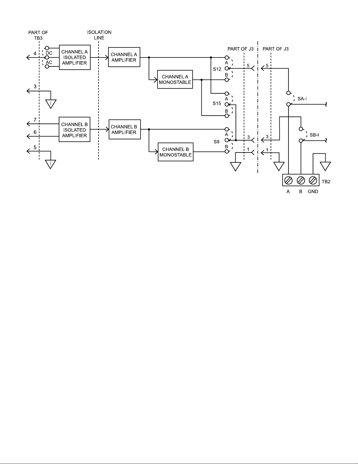
OUTPUTS
The outputs of the signal conditioner channels are connected to the main board through the
J3 connector. These outputs can be connected to the A and B inputs of the meter (pins 1 and 2
of TB2) by installing push-on jumpers on the I positions of SA and SB (Figure 1-2). Each output
can drive 10 LSTTL load (5 LSTTL when debounce monostable is bypassed) and is TTL / 5 V
CMOS compatible
.
In a single-channel signal conditioner (Channel A only), the output can be connected to either
or both A and B outputs by installing jumpers on the appropriate positions of S9, S12 and S15
(see Figure 1-5). However, when a jumper is installed on A or B position of S15, the S9
jumper must be removed.
Page 10
6
Figure 1-2 Simplified Block Diagram of the Signal Conditioner
EXCITATION OUTPUT
A 12.4 V regulated excitation voltage is available on pins 1 and 2 of TB3 (Figure 1-1). This
voltage can be used to drive external transducers with operating currents up to 20 mA.
It should be noted that this voltage is isolated from the main board ground, not from the
isolated ground. Excitation HI and Excitation LO are +6.2 and -6.2 V respectively referenced
to isolated ground.
The EXC LO must not be connected to ISO GND
INPUT FILTER
Jumpers at S1 and S5 connect two .033 uF or .0022 uF capacitors to form an RC low-pass
filter for each input. The time constants of these filters are about 2.5 and .17 milliseconds.
When the input is a contact closure (between EXC HI and ISO DC input), the capacitor is
discharged through a 1 MOhm resistor to ISO GND, providing a time constant of
33 milliseconds. In this case, the trigger level should be adjusted between 0 and +2 V.
Page 11

7
1.5 TRIGGER LEVEL ADJUSTMENT
Two multiturn potentiometers in the Dual-Channel Signal Conditioner (P6A2A) or one
multiturn potentiometer in the Single-Channel Signal Conditioner (P6A1A) are provided to
adjust the trigger level of each channel independently. The P6A2A potentiometers are
accessible through a hole on the top, left-hand side of the case, with the sleeve removed.
The P6A1A has two potentiometers, each in a different location for easy access, depending
on which meter you are using it with. In a P6000A/DPF6000 the potentiometer is accessible
through a hole on the left-hand side of the display board, with the lens removed; S17-B
jumper must be installed.* In a P5000/DPF5000 the potentiometer is accessible through a
hole on the top, left-hand side of the case, with the sleeve removed; S17-A jumper must be
installed. Refer to drawing below and Figure 1-1.
Meter Jumper Position Potentiometer Location
P6000A/DPF6000 S17-B* Through hole in display board
P5000/DPF5000 S17-A Through hole in top of case
Table 1-3 P6A1A Potentiometer Selection
* Factory default position
Figure 1-3 P6A1A Potentiometer/Jumper Locations
When these potentiometers are in their extreme right or left positions, the trigger level may
exceed the maximum positive or negative working voltage of the amplifier.
To adjust the trigger level to about +1 V, turn to the extreme clockwise position of the pot.
Then, turn the pot counter-clockwise six turns. Now the trigger level is about 1 V (1.0 ±.5 V).
To adjust the trigger level to zero, turn the pot counter-clockwise 2.5 more turns.
The positive going trigger level is higher than the negative going trigger level by the selected
hysteresis value.
Page 12

8
1.6 HYSTERESIS SELECTION
The signal conditioner option offers three selectable hysteresis values for each channel.
The hysteresis may be higher than its nominal value when the trigger level is other than zero.
For trigger levels out of the ±2 V range, the hysteresis becomes significantly larger than the
nominal value.
1.7 DEBOUNCING MONOSTABLE CIRCUIT
Each channel contains a monostable circuit with jumper-selectable time constants. Trigger
slope is also selectable. Refer to Section 1.8 Configuration for the jumper settings.
These retriggerable monostables can be used for debouncing a mechanical switch (Figure 1-4).
Figure 1-4 Debouncing a Mechanical Switch
ISO IN
ISO OUT
DEBOUNCE TIME
* * *
= TRIGGER EDGE
Page 13

9
1.8 JUMPER CONFIGURATION
FUNCTION CHANNEL A CHANNEL B
Install Remove Install Remove
Input resistance = 1 MΩ pull-down to ISO GND, S2, S3* S6, S7*
max input voltage = 260 V rms
Input resistance = 3 kΩ pull-down to EXC LO, S2-A S3 S6-A S7
max input voltage = +15/-20 V dc
Input resistance = 1 kΩ pull-up to +2 V ref to ISO GND S2-A, S3-A S6-A, S7-A
max input voltage = +15/-10 V dc
No filter S1* S5*
Low pass filter in circuit, time constant = 2.5 ms S1-A S5-A
Low pass filter in circuit, time constant = .17 ms S1-B S5-B
Hysteresis = 700 mV (use when input > 2 V) S4-A S8-A
Hysteresis = 70 mV (use when .2 V < input < 2 V) S4 S8
Hysteresis = 10 mV (use when input <.2 V) S4-B* S8-B*
Monostable trigger on positive edge S14-A* S11-A*
Monostable trigger on negative edge S14-B S11-B
Monostable bypassed (no debounce time) S12-A* S9-A*
Monostable in circuit S12-B S9-B
Debounce time = 120 ms S13-A* S10-A*
Debounce time = 22 ms S13 S10
Debounce time = 1 ms S13-B S10-B
Connects channel A output to channel B, S15-A
monostable bypassed
Connects channel A output to channel B, S15-B*
monostable in circuit
No Connection S15
Channel A, AC coupled S16-AC*
Channel A, DC coupled S16-DC
Table 1-4 Jumper Configuration
* Default position; changes may be required for some applications.
S15 is not supplied in the dual-channel signal conditioners.
Page 14

10
1.9 SPECIFICATIONS
Input impedance Input < ±500 mV: 1 MΩ
(ISO DC INPUT) Input > ±500 mV: More than 70 kΩ
Frequency response for a
square-wave input Input = ±10 mV: 0-1 kHz (min)
Input = ±25 mV: 0-20 kHz (min)
Input = ±50 mV: 0-100 kHz (typ)
Maximum input voltage 260 V rms
Max Common Mode Voltage
(ISO GND refer to GND) 350 V, peak
Max DC blocking voltage
(ISO AC INPUT) 250 V dc
Hysteresis 10, 70 or 700 millivolts
Trigger level (nominal) -2 to +2 V, adjustable
Monostable time constant 1, 22 or 120 milliseconds
Propagation delay
(monostable bypassed) 6-10 microseconds (typ)
Page 15

11
1.10 DRAWINGS
Figure 1-5 Isolated Signal Conditioner Assembly Diagram
R22
R29
R20
R19
S7
TB3
C2
S3
R51
R52
R50
R17
TB3
R16
C12
7
6
L1
S6
E2
R18
R54
R53
C8
AC
R5
R4
C21
C3
CR1
5
4
L2
3
2
C1
C22
S2
S16
DC
R49
R6
CR2
U1
R8
R55
R27
R56
C14
C11
CR7
CR6
CR5
C9
S5
R28
C26
U3
C10
C4
S1
CR4
CR8
CR3
R7
C7
C5
R1
C25
R2
E1
U2
C13
C27
1
C24
C23
8
1
B
A
S17
C19
R34
R32
R25
R43
A
E3
R23
R24
R21
B
S8
R14
U5
R26
R39
R13
R11
S4
R12
R9
R10
C28
U4
U6
C29
R48
R57
R40
R41
U7
R44
R45
R46
C18
C30
R38
R42
A
S14
B
C17
S12
S11
S13
A
B
A
A
B
B
R47
R33
R37
R35
R31
C20
R30
C16
C15
A
S10
B
S15
A
B
S9
R36
A
B
A
B
A
B
AB
S1 A B S15AB
S16
DC
AC
S17 A B
DWG. NO.
11357AY-02 B
S9AB
S8AB
S10AB
S11AB
S12AB
S13AB
S14AB
S2 A
S3 A
S6 A
S7 A
S4 A B
S5 A B
Page 16

12
Figure 1-8 Main Board Assembly Diagram
F
S
F
S
SB
19
SA
I
I
1 2
18
C20
TB2
L2L1
U11
R6R5R4
C3
R2
C2
R1
R10
R3
C23
C22
R31
R30
U10
TF2
C29
R29
U6
U8
Y1
W1
C15
XU5
CR1
C13
P2
CR7
R20
R19
Q1
R22
P1
R12
Q6
R27
R13
C10
CR2
CR3
C11
C5
C12
C17
U1
E1
Q2
R18
C9
R24
C7
R11
R21
R17
R25
R9
C8
U3
Q5
CR4
Q4
R26
R23
P3
E2
C6
C19
C16
U4
R15
U2
R16
U7
U5
U12
C21
C27
C26
TF1
C25
R14
R8
R41
R44
R42
R32
C18
U9
R28
Q9
R33
Q8
Q10
R36
R38
R35
R34
Q11
Q12
R43
R40
R37
R39
R45
Q7
C24
Q13
R7
C14
1 2
C4
C1
Q3
SA
SB
I
S
F
M
I
S
F
M
DWG. NO.
11364AY-02 B
Page 17

13
SECTION TWO
NON-ISOLATED SIGNAL CONDITIONER OPTION
2.1 GENERAL
This provides a non-isolated amplifier and a debouncing monostable that can be used to
interface a wide range of signal sources to the meter, if isolation is not required. In
addition, a 16 V / 25 mA excitation is available that can be used to power an external active
sensor.
2.2 MECHANICAL INSTALLATION
The signal conditioning board is positioned as a mezzanine and is supported by the rear
panel and P3-J3 header-connector. See Figure 2-1.
Figure 2-1 Exploded View with Power & Signal Connector
Page 18

14
TO INSTALL:
IMPORTANT: Turn-off the power and input signals from the unit before proceeding.
Failure to do so may result in injury!
CAUTION: The meter has no power-on switch; it will be in operation as soon as you
apply power. To change the factory preset jumpers, disconnect the power from the
unit. Failure to do so may result in injury! The jumpers must be changed by specially
trained personnel.
1. When using a signal conditioning board with the meter, the main board must
be jumper configured prior to installation. Install SA-I and SB-I (main board). Refer to
Section 2.5 CONFIGURATION for jumper selection of input and output features.
2. Position J3, an 8-pin connector on the circuit side of the signal conditioner, to mate
with the P3 pins on the main board. Press the board downward until the rear
connectors rest on the lower rear panel.
3. Install the upper rear panel.
2.3 ELECTRICAL CONNECTIONS
The following table provides wiring and jumper configuration for commonly used signal
sources. See Figure 2-2 below for a rear view of the meter. The exploded view and
assembly diagram/schematics further illustrate parts affected, such as connector TB3 for
signal inputs and outputs, jumper locations, or connector P2.
The main assembly diagram is identical for the isolated and non-isolated and non-isolated
signal conditioners. This is located in Section 1.10, Figure 1-8.
Figure 2-2 Rear View
P1
TB1J
BA
TB3J
P2
TB2J
Page 19

15
Input Type Input Requirement Wiring Jumper Position
Passive Inductor Voltage < 60 V rms Connect the signal Remove S4. Install
Pickup High level > 120 mV wires to SIG IN and S1, S2-A and S3-A.
Low level < 20 mV EXC LO
Active Transducer Operating Voltage Connect EXC HI and Remove S1. Install
(inductive, optic or = 16 V (Note 1) LO to the positive S2-A, S3-A and S4-A.
capacitive), with NPN Operating Current and negative supply
open-collector output < 25 mA inputs of transducer.
Connect the output
to SIG IN.
TTL or CMOS- Signal source should Connect the signal Remove S1. Install
compatible signal be powered externally and GND to the SIG S2-A and S3-B. Install
or with +5 V of the IN and EXC LO. S4-A for TTL, remove
main board. S4-A for CMOS.
Contact closure Max of 10 actuation Connect the contact Remove S1. Install
(Slow) per second wires to SIG IN and S2-B, S3-A, and S4-A.
EXC LO.
Contact closure Max of 70 actuation Connect the contact Remove S1 and S2.
(Fast) per second wires to SIG IN and Install S3-A and S3-4.
EXC LO.
NAMUR NAMUR standard Connect the positive Remove S1. Install
and negative inputs S2-A, S3-B, and S4-B.
of sensor to EXC HI
and SIG IN.
Table 2-1 Required Wiring for Most Commonly Used Sensors
Note 1: For 8.2 V excitation, install S3-B; for 20 V excitation, remove S3-A & S3-B.
(Maximum current is 16 mA.)
Page 20

16
2.4 INPUTS AND OUTPUTS
Excitation outputs are available on the TB3 connector, EXC HI (positive) on pin 2 and EXC LO
(negative) on pin 1.
Excitation Output S3 Jumper Position
16 V at 25 mA Install S3-A
(AC-powered units only) 8.2 V at 16 mA Install S3-B
20 V at 16 mA Remove jumper
Signal input, the input of the signal conditioner amplifier, is available on pin 3 of TB3.
RESET output is available on pin 3 of connector TB3. When the input is missing for more
than 1.5 seconds, a negative true pulse is generated on this output that can be used to reset
the meter. To do this, connect this output to the reset input of the meter, P2-pin 18.
Signal output is internally connected to the main board. SA-I must
be installed. Refer to the
drawings section.
Page 21

17
2.5 CONFIGURATION
FUNCTION PIN JUMPER
GROUP POSITION
Excitation voltage = 16 V, S3* A
max current = 25 mA
Excitation voltage = 8.2 V, S3 B
max current = 16 mA
Excitation voltage = 20 V, S3 None
max current = 16 mA
(AC powered units only)
7.5 k pull-up to +5 V input S4 A
1 k pull-down to EXC LO input S4 B
160 k pull-down to EXC LO S4* None
Debounce time = 15 µsec S2* A
Debounce time = 80 msec S2 B
Debounce time = 10 msec S2 None
Hysteresis = 40 mV, High threshold = 85 mV S1* Installed
Low threshold = 45 mV
Hysteresis = 1.4 V, High threshold = 2.8 V S1 Removed
Low threshold = 1.4 V
* Default Position
Table 2-2 Jumper Configuration
Unless otherwise specified, factory settings are:
16 volts excitation
160 k pull-down to EXC LO
15 microseconds debounce time
40 millivolts hysteresis; high threshold 85 mv, low threshold 45 mv
2.6 SPECIFICATIONS
Input impedance: More than 50 kOhms
Operating frequency: DC to 10 kHz
Hysteresis: 40 mV or 1.4 V, jumper-selectable
Operating input voltage: 0 - 120 mV min; 60 V rms max
(S4 removed)
Page 22

18
2.7 DRAWINGS
Figure 2-3 Non-Isolated Signal Conditioner Assembly Diagram
Page 23

19
SECTION THREE
ANALOG INPUT OPTION
3.1 GENERAL
The P6A5B analog input board allows the meter to serve as a process meter or as
a totalizer for process signals. For instance, it can display watts or totalized kilowatt-hours
based on the 0-1 mA signal from a watt transducer. It can display flow rate in gallons per
minute or totalized gallons based on the 4-20 mA signal from a flow transducer.
The P6A5B converts an input voltage or current to a frequency using a V/F converter. This
frequency can then be processed by the host meter in either the Frequency or
Totalize modes.
The P6A5B can be configured to operate in one of the ranges shown in Table 3-2. The
factory default range setting is 4-20 mA.
Page 24

20
3.2 MECHANICAL INSTALLATION
The analog input board is positioned as a mezzanine inside the case. It is supported by the
rear panel and a slot on the display board.
NOTE: Before installing the Analog input board, install push-on jumpers SA-I and SB-I on
the main board.
Figure 3-1 Exploded View with Power & Signal Connector
Page 25

21
TO INSTALL:
IMPORTANT: Turn-off the power and input signals from the unit before proceeding.
Failure to do so may result in injury!
CAUTION: The meter has no power-on switch; it will be in operation as soon as you
apply power. To change the factory preset jumpers, disconnect the power from the
unit. Failure to do so may result in injury! The jumpers must be changed by specially
trained personnel.
1. Install SA-I and SB-I jumpers on the main board. If not factory-configured, install or
remove jumpers as indicated in Section 3.3.
2. The insulator rests atop the lower rear panel, with the two tabs fitting into holes on the
display board. Insert the tab of the analog input board into the slot provided on the
display board.
3. Position J3, an 8-pin connector on the circuit side of the signal conditioner, to mate
with the P3 pins on the main board. Press the board downward until the rear
connectors rest on the lower rear panel.
4. Install the upper rear panel.
3.3 ELECTRICAL CONNECTION AND CONFIGURATION
The input signal is applied across TB3-7 (SIG HI) and TB3-6 (SIG LO). A 24 V excitation
voltage is available at TB3-5. To use the excitation supply to power the current loop, use
TB3-5 for "+" and TB3-7 for the return (see Table 3-2).
The output frequency of the P6A5B module is internally connected to the A input, TB2-1 of
the main board via the SA-I
jumpers of the main board.
If the P6A5B did not come installed in the meter, the proper ranging/configuring jumpers need
to be installed. Choose the proper range from Table 3-2. The factory calibrates the module to
4-20 mA = 0-10,000 counts by adjusting the offset pot for zero at 4 mA input and writing the
required meter SCALE factor for 10,000 counts on the back of the board. If a different range is
required the scale factor will be different (see Section 3.7, CALIBRATION).
Page 26

22
ZERO ADJUSTMENT
If the P6A5B is to be used in a totalizing application, the multiturn potentiometer must be
adjusted for proper reading when the output frequency of the P6A5B module is low but not
zero. The P6A5B has two potentiometers, each in a different location for easy access,
depending on which meter you are using it with. In a P6000A/DPF6000 meter the zero offset
potentiometer is accessible through a hole on the left-hand side of the display board, with the
lens removed; S3-B jumper must be installed*. In a P5000/DPF5000 meter, the zero offset
potentiometer is accessible through a hole on the top, left-hand side of the case, with the
sleeve removed; S3-A jumper must be installed. Refer to drawing below and Figure 3-1.
Meter Jumper Position Potentiometer Location
P6000A/DPF6000 S3-B* Through hole in display board
P5000/DPF5000 S3-A Through hole in top of case
Table 3-1 P6A5A Potentiometer Selection
* Factory default position
Figure 3-2 P6A5A Potentiometer/Jumper Locations
If the P6A5B is to be used in a non-totalizing application, the zero offset can be adjusted via
the potentiometer, or programmed digitally. In case of programming, it is better to turn the
multiturn potentiometer counter-clockwise to generate an output frequency when the input is
minimum (e.g., 4 mA in 4-20 mA range). This offset, can then be cancelled with a negative
digital offset when the meter is in Frequency mode. This method improves the
display update rate at low frequencies. It also ensures that the frequency output of the P6A5B
module is above the cut-off limit (Section 3.4).
SPAN ADJUSTMENT
Span is adjustable by programming the meter Scale Factor. No potentiometer is
provided.
Page 27

23
INPUT RANGE SELECTION TB3 WIRING
JUMPERS
4-20 mA S1-A, S1-C, S1-D
(Default)
0-1 mA S1-B, S1-C, S1-E
0-5 V S1 Removed
1-5 V S1-D
0-10 V S1-E
Table 3-2 Jumper Positions and Input Wiring for Different Ranges
Page 28

24
S2 POSITION STORAGE S2-A S2-B S2-C
CUTOFF NO CUTOFF 200-300 Hz 40-60 Hz 8-12 Hz
FREQUENCY (DEFAULT)
Table 3-3 Cutoff Frequency Selection
3.4 LOW FREQUENCY CUTOFF
In some applications, it is desirable to cut off the output frequency below a certain limit to
prevent accumulating a leakage over a long period of time. Table 3-2 lists the cutoff
frequency for different positions of S2.
An active low logic signal is provided on TB3-1 when the output frequency is cut off. This
signal is referenced to Digital GND (TB2-3) and is electrically isolated from the input.
3.5 OPEN CIRCUIT INDICATION
The cutoff signal (available on TB3-1) can be used to show an open current loop in the 4-20 mA
range in rate indication applications. To make sure that the output remains above the cutoff limit
under normal conditions:
1. Turn the offset adjustment pot counter-clockwise until display reads more than 350 counts
with 4 mA input and write down the reading.
2. Program the meter offset to the negative of the above value. The display then
shows zero for 4 mA input.
3.6 POWER
The P6A5B board is powered by the host meter. A 24 V regulated excitation voltage
is available on TB3-5. A maximum of 25 mA may be drawn from this output.
Page 29

25
3.7 CALIBRATION
If the meter is ordered as a configured unit with this option (P6XX4A/P5XX4), the
push-on jumpers and the offset pot are configured for the 4-20 mA range (default). The
meter’s scale factor* is set for a 10,000 reading at full scale input (20 mA). The offset
can be adjusted by the multiturn potentiometer, see section 3.3 for location.
If a different full scale value is all that is desired, simply modify the meter scale factor
as follows:
Required Scale Factor =
Desired Full Scale
x Present Scale Factor
10,000
* This scale factor is also written on the back side of the board.
To calibrate the analog input board in any range
:
1. Put the meter in the Frequency mode, remove the S2 jumper, and apply a high
input (close to full scale), and write down the reading.
2. Apply a low input, about 10% of the input span (e.g., 5.6 mA for 4-20 mA input), and write
down the reading.
3. Calculate and modify the scale factor (A .SC) using this formula:
Scale Factor =
DH - DL
PH - PL
Where: DH = Desired reading with high input
DL = Desired reading with low input
PH = Present reading with high input
PL = Present reading with low input
4. While a low input is applied, adjust the offset using the multiturn potentiometer for the
desired reading, see section 3.3 for location.
In a non-totalizing application (Frequency mode), the meter digital offset
can be programmed instead of adjusting the potentiometer.
Meter’s Offset = Desired Reading - Present Reading
3.8 SPECIFICATIONS
Signal Ranges 4-20 mA 0-1 mA 0-5 V 1-5 V 0-10 V
Resolution 1.6 µA 0.1 µA 0.5 mV 0.4 mV 1.0 mV
Input Resistance 24.3 Ω 381 Ω >10 MΩ >10 MΩ >10 MΩ
Bias Current - - 10-50 nA 10-50 nA 10-50 nA
Absolute Maximum Input 80 mA 20 mA 130 V 130 V 130 V
Table 3-4 Analog Input Signal Range Specifications
Page 30

26
Excitation output 23.5 ± 2 V at 25 mA max.
CMR More than 100 db, DC to 60 Hz
NMR Gate Time = 00.20 sec: 56 db, min
Gate Time = 00.50 sec: 64 db, min
Response Time Gate Time = 00.20 sec: .45 - .65 sec
(to 99.9% of span) Gate Time = 00.50 sec: .75 - 1.25 sec
Accuracy at 25°C 99.95% of the span
(RH 25-75%)
Nonlinearity .02% of full scale, maximum
Typical Temperature stability 0-1 mA ±.010% / °C
of the span, % of FS 4-20 mA: ± .005% / °C
0-5 V, 1-5 V, 0-10 V ± .005% / °C
Temperature stability Less than 0.1 Hz / °C (1 Hz / 10°C)
of the offset
Warm up to rated accuracy: 30 minutes
Full-scale reading Programmable by meter’s scale factor
Full-scale output 6.5 KHz ± 20%
frequency
Overrange capability 10% above full scale, minimum
Offset adjustment with multiturn pot: 5% of span, typ.
with meter’s offset: -99,999 to 999,999
Isolation 350 V dc between output and input
(output is connected to main board)
Operating temperature 0-60°C
Humidity 5-95% non-condensing, 0-40°C
Page 31

WARRANTY/DISCLAIMER
OMEGA ENGINEERING, INC. warrants this unit to be free of defects in materials and workmanship for a
period of 13 months from the date of purchase. OMEGA’s Warranty adds an additional one (1) month
grace period to the normal one (1) year product warranty to cover handling and shipping time. This
ensures that OMEGA’s customers receive maximum coverage on each product.
If the unit malfunctions, it must be returned to the factory for evaluation. OMEGA’s Customer Service
Department will issue an Authorized Return (AR) number immediately upon phone or written request.
Upon examination by OMEGA, if the unit is found to be defective, it will be repaired or replaced at no
charge. OMEGA’s WARRANTY does not apply to defects resulting from any action of the purchaser,
including but not limited to mishandling, improper interfacing, operation outside of design limits, improper
repair, or unauthorized modification. This WARRANTY is VOID if the unit shows evidence of having been
tampered with or shows evidence of having been damaged as a result of excessive corrosion; or current,
heat, moisture or vibration; improper specification; misapplication; misuse or other operating conditions
outside of OMEGA’s control. Components which wear are not warranted, including but not limited to
contact points, fuses, and triacs.
OMEGA is pleased to offer suggestions on the use of its various products. However, OMEGA
neither assumes responsibility for any omissions or errors nor assumes liability for any damages
that result from the use of its products in accordance with information provided by OMEGA,
either verbal or written. OMEGA warrants only that the parts manufactured by it will be as
specified and free of defects. OMEGA MAKES NO OTHER WARRANTIES OR REPRESENTATIONS
OF ANY KIND WHATSOEVER, EXPRESS OR IMPLIED, EXCEPT THAT OF TITLE, AND ALL IMPLIED
WARRANTIES INCLUDING ANY WARRANTY OF MERCHANTABILITY AND FITNESS FOR A
PARTICULAR PURPOSE ARE HEREBY DISCLAIMED. LIMITATION OF LIABILITY: The remedies of
purchaser set forth herein are exclusive, and the total liability of OMEGA with respect to this
order, whether based on contract, warranty, negligence, indemnification, strict liability or
otherwise, shall not exceed the purchase price of the component upon which liability is based. In
no event shall OMEGA be liable for consequential, incidental or special damages.
CONDITIONS: Equipment sold by OMEGA is not intended to be used, nor shall it be used: (1) as
a “Basic Component” under 10 CFR 21 (NRC), used in or with any nuclear installation or activity; or
(2) in medical applications or used on humans. Should any Product(s) be used in or with any nuclear
installation or activity, medical application, used on humans, or misused in any way, OMEGA
assumes no responsibility as set forth in our basic WARRANTY/DISCLAIMER language, and,
additionally, purchaser will indemnify OMEGA and hold OMEGA harmless from any liability or
damage whatsoever arising out of the use of the Product(s) in such a manner.
RETURN REQUESTS/INQUIRIES
Direct all warranty and repair requests/inquiries to the OMEGA Customer Service Department.
BEFORE RETURNING ANY PRODUCT(S) TO OMEGA, PURCHASER MUST OBTAIN AN
AUTHORIZED RETURN (AR) NUMBER FROM OMEGA’S CUSTOMER SERVICE DEPARTMENT
(IN ORDER TO AVOID PROCESSING DELAYS). The assigned AR number should then be marked
on the outside of the return package and on any correspondence.
The purchaser is responsible for shipping charges, freight, insurance and proper packaging to
prevent breakage in transit.
FOR WARRANTY RETURNS, please have the
following information available BEFORE
contacting OMEGA:
1. Purchase Order number under which the product
was PURCHASED,
2. Model and serial number of the product under
warranty, and
3. Repair instructions and/or specific problems
relative to the product.
FOR NON-WARRANTY REPAIRS,
consult
OMEGA for current repair charges. Have the
following information available BEFORE
contacting OMEGA:
1. Purchase Order number to cover the COST
of the repair,
2. Model and serial number of product, and
3. Repair instructions and/or specific problems
relative to the product.
OMEGA’s policy is to make running changes, not model changes, whenever an improvement is possible. This affords
our customers the latest in technology and engineering.
OMEGA is a registered trademark of OMEGA ENGINEERING, INC.
© Copyright 2003 OMEGA ENGINEERING, INC. All rights reserved. This document may not be copied, photocopied,
reproduced, translated, or reduced to any electronic medium or machine-readable form, in whole or in part, without the
prior written consent of OMEGA ENGINEERING, INC.
Page 32

Where Do I Find Everything I Need for
Process Measurement and Control?
OMEGA…Of Course!
Shop on line at www.omega.com
TEMPERATURE
Thermocouple, RTD & Thermistor Probes, Connectors, Panels & Assemblies
Wire: Thermocouple, RTD & Thermistor
Calibrators & Ice Point References
Recorders, Controllers & Process Monitors
Infrared Pyrometers
PRESSURE, STRAIN AND FORCE
Transducers & Strain Gauges
Load Cells & Pressure Gauges
Displacement Transducers
Instrumentation & Accessories
FLOW/LEVEL
Rotameters, Gas Mass Flowmeters & Flow Computers
Air Velocity Indicators
Turbine/Paddlewheel Systems
Totalizers & Batch Controllers
pH/CONDUCTIVITY
pH Electrodes, Testers & Accessories
Benchtop/Laboratory Meters
Controllers, Calibrators, Simulators & Pumps
Industrial pH & Conductivity Equipment
DATA ACQUISITION
Data Acquisition & Engineering Software
Communications-Based Acquisition Systems
Plug-in Cards for Apple, IBM & Compatibles
Datalogging Systems
Recorders, Printers & Plotters
HEATERS
Heating Cable
Cartridge & Strip Heaters
Immersion & Band Heaters
Flexible Heaters
Laboratory Heaters
ENVIRONMENTAL
MONITORING AND CONTROL
Metering & Control Instrumentation
Refractometers
Pumps & Tubing
Air, Soil & Water Monitors
Industrial Water & Wastewater Treatment
pH, Conductivity & Dissolved Oxygen Instruments
M912/0103 11357ML-99D
 Loading...